A mini steam turbine electric generator is a smaller version of a micro steam turbine. It shares the same fundamental principles of converting steam energy into electricity but operates at an even lower scale.
Key Characteristics
Smaller Size: Compared to micro turbines, these units are even more compact, suitable for very limited spaces.
Lower Power Output: Typically generates lower amounts of electricity, ranging from a few kilowatts to tens of kilowatts.
Specialized Applications: Often designed for niche applications where space constraints and low power requirements are critical.
Applications
Industrial Process Heat Recovery: Recovering waste heat from small-scale industrial processes to generate electricity.
Residential Heating and Power (CHP): Generating both electricity and heat for homes or small businesses.
Marine Applications: Powering small boats or auxiliary systems on larger vessels.
Educational Demonstrations: Used in schools and universities to teach the principles of thermodynamics and power generation.
Challenges and Considerations
Lower Efficiency: Due to their smaller size, mini steam turbines may have slightly lower efficiency compared to larger units.
Complex Design: Developing efficient and reliable mini turbines requires advanced engineering and manufacturing techniques.
Cost: The cost per kilowatt-hour of electricity generated by mini turbines can be higher compared to larger systems.
Future Outlook
Despite these challenges, advancements in materials science and manufacturing technologies are paving the way for more efficient and affordable mini steam turbine generators. As the demand for distributed power generation and energy efficiency grows, these devices have the potential to become increasingly important.
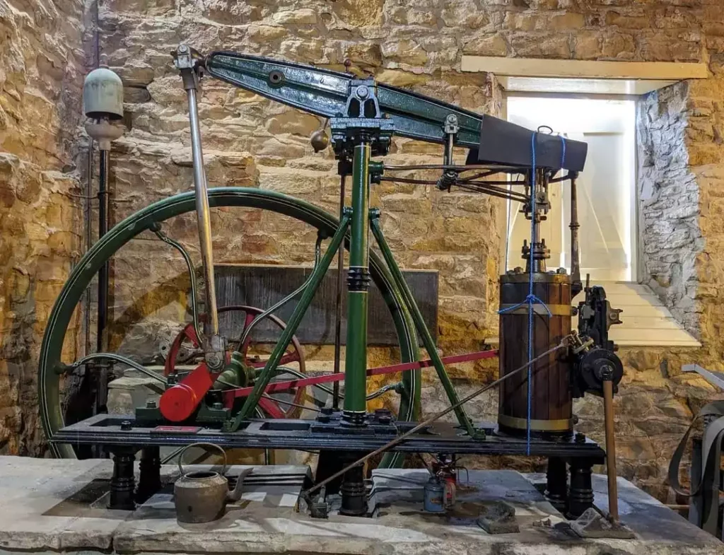
A steam engine power generator is a device that converts the energy from steam into mechanical work and subsequently into electricity. Steam engines were historically used as prime movers for a wide range of applications, including power generation, and they played a crucial role during the industrial revolution. While they have largely been replaced by more efficient and modern technologies in many applications, steam engines are still used in some niche and historical contexts. Here’s a basic overview of how a steam engine power generator works:
Boiler: The process starts with a boiler, which is a vessel designed to heat water to produce steam. The boiler is typically heated by burning a fuel source, such as coal, wood, natural gas, or oil. In some cases, electrical resistance heating or other methods can be used to generate steam.
Steam Generation: Water is pumped into the boiler, where it is heated to produce high-pressure steam. The steam can reach temperatures and pressures significantly higher than the boiling point of water, which is essential for generating mechanical work efficiently.
Steam Engine: The high-pressure steam is directed to a steam engine, which is a mechanical device that converts the thermal energy of the steam into mechanical work. Steam engines typically consist of a cylinder with a piston inside. The high-pressure steam is admitted to one side of the piston, causing it to move. This movement is converted into rotational motion, which can be used to drive machinery or, in the context of power generation, to drive a generator.
Generator: The rotational motion produced by the steam engine is connected to an electrical generator. The generator consists of a rotor and a stator, similar to the setup in a steam turbine generator. As the rotor spins, it induces an electrical current in the stator windings through electromagnetic induction. This electrical current is the electricity generated by the system.
Electricity Generation: The electricity generated is typically in the form of alternating current (AC). It can be conditioned and transformed to the desired voltage and frequency using transformers and other electrical equipment before being distributed or used.
Condenser: After performing its work in the engine, the low-pressure steam is usually condensed back into water in a separate condenser. This condensed water is then returned to the boiler to be heated again, completing the steam cycle.
Steam engine power generators were widely used in the past, but they have largely been replaced by more efficient and less polluting technologies such as gas turbines, steam turbines, and internal combustion engines. However, some historic steam engine generators are still operational in museums and for specialized applications.
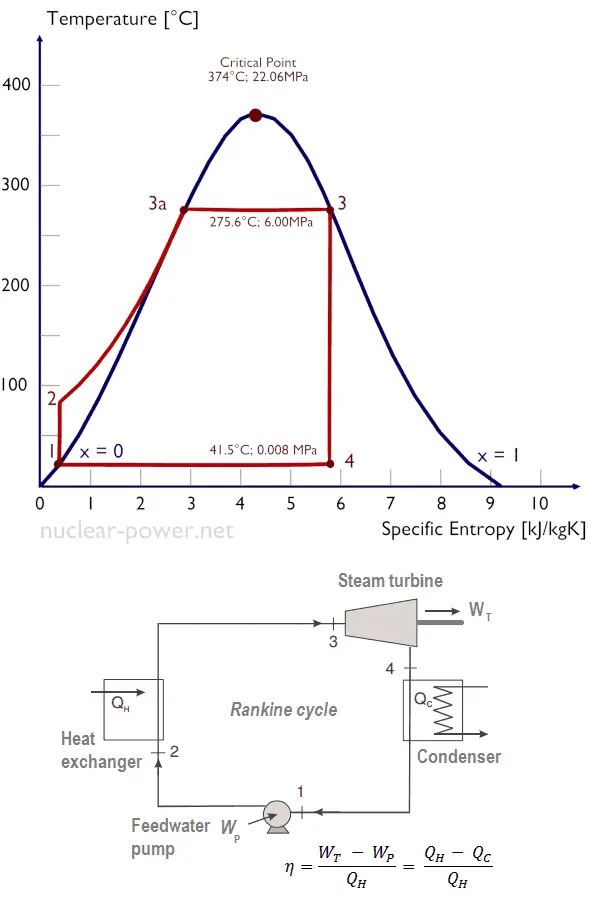
Steam Turbine
Steam Turbine
We manufacture Steam turbines for sale. Steam turbine generator power machines for sale price from the manufacturer. High quality and low price with a guaranty
A steam turbine is a device that converts the thermal energy of steam into mechanical energy, which can then be used to generate electricity or perform mechanical work. Steam turbines are widely used in power plants, industries, and marine applications.
Here’s a basic overview of how a steam turbine works:
Steam Generation: Steam is generated by heating water. This can be achieved by burning fossil fuels (coal, natural gas, oil), using nuclear reactions, or harnessing renewable energy sources like solar or geothermal.
Expansion of Steam: The high-pressure steam produced in the boiler is directed into the steam turbine. The steam enters the turbine at a high velocity and pressure.
Blades and Rotors: The steam flows through a series of blades mounted on rotors. As the steam passes over these blades, it causes the rotor to spin. The spinning rotor is connected to a shaft.
Mechanical Work: The kinetic energy of the rotating rotor is converted into mechanical work. This work can be used to turn an electrical generator, drive machinery, or perform other tasks.
Exhaust: After passing through the turbine blades, the steam exits the turbine at a lower pressure and temperature. This low-pressure steam is then condensed back into water and returned to the boiler to be reheated and used again.
Steam Turbine
Steam Turbine
Steam turbines play a crucial role in a wide range of industrial applications, providing efficient and reliable power generation for various processes and equipment. Their versatility, durability, and ability to operate in demanding environments make them an essential component of modern industrial machinery.
Key Characteristics of Steam Turbines in Industrial Applications:
High Efficiency: Steam turbines are known for their high efficiency in converting thermal energy from steam into mechanical energy. This efficiency can reach up to 40%, making them a cost-effective and energy-efficient power source for industrial applications.
Reliability and Durability: Steam turbines are designed to withstand the rigors of industrial use, operating continuously for extended periods with minimal maintenance. Their robust construction and proven technology make them a reliable and long-lasting power source.
Scalability: Steam turbines can be scaled to meet the power requirements of a wide range of industrial applications, from small-scale processes to large-scale power plants. Their adaptable design allows for flexibility in power generation capacity.
Adaptability to Various Fuels: Steam turbines can be driven by steam generated from a variety of fuels, including fossil fuels, biomass, and geothermal energy. This flexibility allows them to adapt to different industrial settings and fuel availability.
Environmentally Friendly Alternative: Compared to internal combustion engines, steam turbines produce lower emissions of greenhouse gases and pollutants. This makes them a more environmentally friendly option for power generation in industrial applications.
Applications of Steam Turbines in Various Industrial Sectors:
Power Generation: Steam turbines are widely used in power plants to generate electricity for industrial facilities, commercial buildings, and residential areas. Their ability to produce large amounts of electricity makes them a cornerstone of modern power generation systems.
Cogeneration Plants: Cogeneration plants simultaneously generate electricity and steam for industrial processes. Steam turbines are a crucial component of cogeneration systems, as they efficiently convert thermal energy into both electricity and steam.
Marine Propulsion: Steam turbines have traditionally been used to propel ships and other marine vessels. Their high power-to-weight ratio and adaptability to various fuel sources make them a viable option for marine propulsion systems.
Mechanical Drive Applications: Steam turbines are used to drive a variety of mechanical equipment in industrial settings, such as pumps, compressors, and blowers. Their ability to provide rotational power makes them versatile for various mechanical drive applications.
District Heating Systems: Steam turbines are employed in district heating systems to generate steam for heating buildings and homes. Their efficient steam production contributes to the overall efficiency and cost-effectiveness of district heating systems.
Future Trends in Steam Turbine Technology for Industrial Applications:
Advanced Materials and Manufacturing Techniques: The development of advanced materials and manufacturing techniques is leading to steam turbines with higher efficiency, durability, and reduced maintenance requirements.
Integration with Smart Grid Technologies: Steam turbine technology is being integrated with smart grid technologies, enabling real-time monitoring, optimization, and control of power generation in response to grid demand and renewable energy integration.
Hybrid Power Systems: Steam turbines are increasingly being integrated with other power generation sources, such as renewable energy systems, to create hybrid power systems that offer improved efficiency, flexibility, and environmental benefits.
Digitalization and Automation: Digitalization and automation are transforming the operation and maintenance of steam turbines, providing real-time data analytics, predictive maintenance capabilities, and remote monitoring for enhanced performance and reliability.
Reduced Emissions and Environmental Impact: Ongoing research and development efforts focus on reducing emissions and the environmental impact of steam turbines, including advancements in carbon capture and storage technologies.
Conclusion:
Steam turbines remain a crucial component of modern industrial applications, providing efficient, reliable, and scalable power generation solutions. Their adaptability to various fuels, ability to integrate with other power sources, and potential for further advancements make them a valuable asset for the future of industrial power generation.
Steam Generation for a Steam Turbine
Steam Generation for a Steam Turbine
Steam generation is the process of producing steam from water. This steam can be used for various purposes, including power generation, heating, and industrial processes. The most common method of steam generation involves the use of a boiler, where water is heated to produce steam. Here is an overview of the steam generation process:
Boiler: A boiler is a device that is designed to convert water into steam by applying heat energy to the water. The heat is usually generated by burning fuel, such as coal, natural gas, oil, or biomass, or by using electricity or renewable energy sources like solar or geothermal.
Combustion or Heat Source: In fossil fuel-fired boilers, combustion occurs in a combustion chamber where the fuel is burned, releasing heat. The heat generated is transferred to the water in the boiler to raise its temperature.
Water Feed: Water is fed into the boiler through a feedwater system. This can be a continuous process to maintain a steady supply of water to the boiler.
Heat Transfer: The heat from the combustion process is transferred to the water in the boiler. This causes the water to reach a temperature at which it turns into steam.
Steam Formation: As the water absorbs heat, it undergoes a phase change from liquid to vapor. The steam produced is then collected in the upper part of the boiler.
Superheating (optional): In some cases, the steam is further heated to increase its temperature and energy content. This process is known as superheating and is done in a separate section of the boiler.
Steam Distribution: Once the steam is generated, it can be distributed through pipelines for various applications. In power plants, the steam is often used to turn turbines connected to generators to produce electricity. In industrial processes, steam is utilized for heating, drying, and other manufacturing operations.
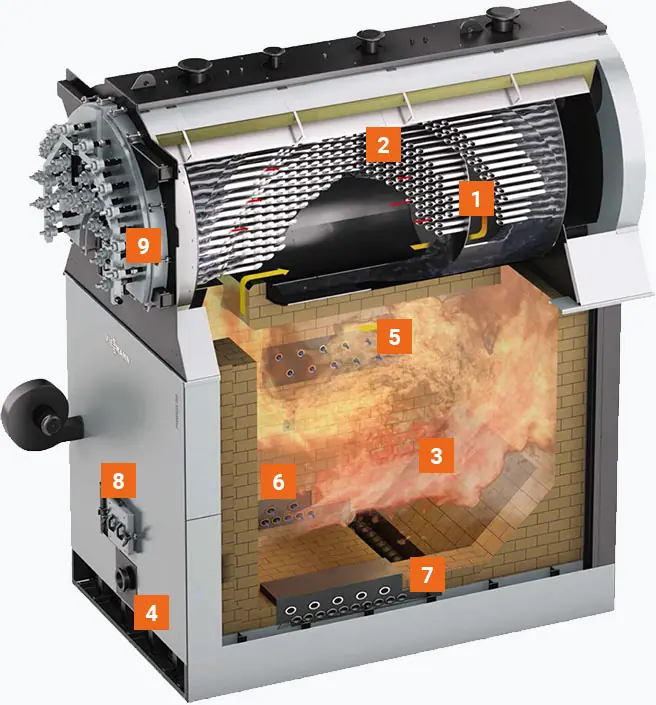
Boiler
A boiler is a closed vessel or apparatus designed to heat water or other fluids. It is an essential component in various industries, as it plays a key role in generating steam for power generation, heating systems, and industrial processes. The basic function of a boiler is to convert water into steam by applying heat energy to the water. Here are the key components and types of boilers:
Key Components of a Boiler:
Burner: The burner is responsible for supplying the heat energy by burning fuel. Common fuels include natural gas, oil, coal, and biomass. The burner releases the heat into the combustion chamber.
Combustion Chamber/Furnace: This is where the fuel is burned to release heat. The combustion chamber is designed to contain and control the combustion process.
Heat Exchanger: The heat exchanger is a component that transfers heat from the combustion gases to the water, causing the water to convert into steam. Heat exchangers can be of various types, including fire-tube, water-tube, and coil-type designs.
Water or Steam Drum: The drum serves as a reservoir for the water or steam. In water-tube boilers, multiple drums may be used to separate different stages of the steam generation process.
Tubes or Coils: These are the pathways through which the hot gases or combustion products flow, transferring heat to the water. In fire-tube boilers, the tubes contain the water, while in water-tube boilers, the water flows through the tubes.
Boiler Shell: The boiler shell is the outer cylindrical part that contains the pressure vessel and other components. It provides structural support and protection.
Controls and Instrumentation: Boilers are equipped with various controls and instrumentation to monitor and regulate the combustion process, water level, pressure, and other parameters.
Types of Boilers:
Fire-Tube Boilers: In these boilers, hot gases pass through tubes that are surrounded by water. The heat is transferred from the tubes to the water, producing steam. Fire-tube boilers are typically used for low to medium pressure applications.
Water-Tube Boilers: In water-tube boilers, water flows through tubes, and combustion gases pass around these tubes. Water-tube boilers are often used in high-pressure applications and large industrial settings.
Electric Boilers: These boilers use electricity to generate heat and are suitable for applications where other fuel sources may be impractical.
Biomass Boilers: These boilers use organic materials, such as wood or agricultural residues, as fuel.
Circulating Fluidized Bed (CFB) Boilers: CFB boilers use a fluidized bed of particles to efficiently burn solid fuels.
The choice of boiler type depends on factors such as the application, required steam pressure, and fuel availability. Boilers are critical components in providing heat and steam for a wide range of industrial and commercial processes, contributing significantly to energy production and various manufacturing operations.
Combustion or Heat Source
Combustion or Heat Source
3-Pass boiler (6 bar – higher pressure ratings on request)
Safety heat exchanger (integrated into boiler)
Combustion chamber
Blow-in ports
Injection of secondary air
Injection of flue gas recirculation
Automatic ash removal from the combustion chamber using a water-cooled screw
Firebox door
Pneumatic boiler tube dedusting (optional)
The combustion or heat source in a boiler is a critical component responsible for generating the thermal energy needed to convert water into steam. The combustion process involves burning a fuel to release heat, and the choice of fuel depends on factors such as availability, cost, and environmental considerations. Common fuels used in boilers include:
Natural Gas: A clean-burning fossil fuel that is widely used for heating and power generation. It produces fewer emissions compared to other fossil fuels.
Oil (Diesel or Heavy Fuel Oil): Liquid fuels that are commonly used in boilers, especially in areas where natural gas availability is limited.
Coal: A traditional and widely used fuel in boilers, especially in power plants. However, coal combustion releases higher levels of carbon dioxide and other pollutants compared to some other fuels.
Biomass: Organic materials such as wood, crop residues, and animal waste can be used as biomass fuel in boilers. Biomass is considered renewable and can contribute to reduced greenhouse gas emissions.
Electricity: Some boilers are electrically powered, using electricity as the heat source. This method is often used in areas where other fuel sources are impractical or expensive.
Renewable Energy Sources: In some cases, boilers can be designed to use renewable energy sources like solar or geothermal energy to generate heat.
The combustion process typically takes place in a combustion chamber or furnace within the boiler. The key steps in combustion include:
Fuel Combustion: The fuel is introduced into the combustion chamber, where it reacts with oxygen from the air. This chemical reaction releases heat energy.
Flame Formation: The heat generated from the combustion reaction results in the formation of a flame. The flame is responsible for heating the surfaces of the boiler, including the heat exchanger or tubes.
Transfer of Heat: The heat from the combustion process is transferred to the water or other fluid in the boiler. This transfer of heat causes the water to reach its boiling point, leading to the production of steam.
Control of Combustion: To ensure efficient and safe operation, combustion in boilers is carefully controlled. This involves monitoring factors such as fuel-air ratio, temperature, and pressure to optimize combustion efficiency and minimize emissions.
Efficient combustion is crucial for the overall performance of a boiler system. Modern boilers often incorporate advanced control systems to regulate the combustion process, ensuring optimal efficiency, minimal environmental impact, and safe operation.
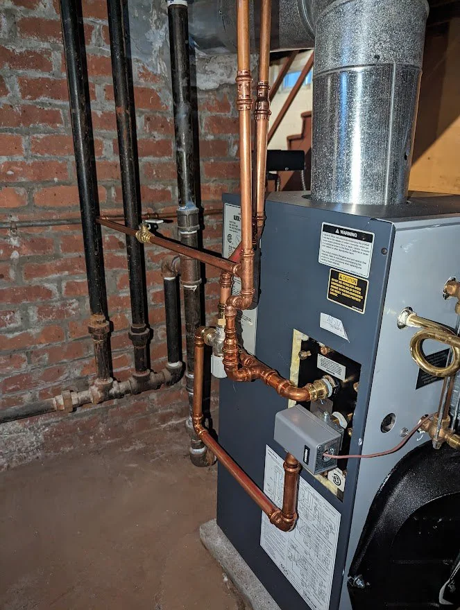
Water Feed
Steam Turbine Boiler Water Feed
The water feed system in a boiler is a crucial component that manages the supply of water to the boiler for steam generation. This system ensures a continuous and controlled supply of water to the boiler, maintaining the desired water level. Proper water feed is essential for efficient and safe boiler operation. Here’s how the water feed system typically works:
Water Source: The water feed system starts with a source of water, which can come from various places depending on the application. It might be from a city water supply, a well, or another water source.
Make-up Water: In many boiler systems, a portion of the water is continuously removed from the system as steam is generated, and this water needs to be replaced. The replacement water is often referred to as make-up water.
Feedwater Pump: The water feed system includes a pump, known as the feedwater pump, which is responsible for delivering the make-up water to the boiler. The pump ensures a consistent flow of water into the boiler.
Feedwater Control Valve: A control valve is often installed to regulate the flow of water into the boiler. This valve is typically controlled by a level sensor or controller that monitors the water level inside the boiler. The valve opens or closes to adjust the flow of water and maintain the desired water level.
Preheating (Optional): In some boiler systems, make-up water may be preheated before entering the boiler. Preheating the water can improve energy efficiency by utilizing waste heat from the flue gases or other sources.
Water Treatment: Depending on the quality of the water source, water treatment processes may be employed to remove impurities and prevent scale or corrosion inside the boiler. This is important for the longevity and efficient operation of the boiler.
Expansion Tank (Optional): In closed-loop systems, an expansion tank may be used to accommodate changes in water volume due to temperature variations. This helps maintain a stable pressure in the system.
The water feed system is designed to maintain the proper water level inside the boiler. If the water level is too low, it can expose the boiler tubes or heating surfaces to excessive heat, leading to potential damage. On the other hand, if the water level is too high, it can result in carryover of water into the steam, which can cause operational issues and reduce the efficiency of the system.
Proper water feed control is essential for the safe and efficient operation of boilers, and it is often automated using control systems to ensure precise and continuous regulation of water flow. Regular maintenance and monitoring of the water feed system are important aspects of boiler management.
Heat Transfer
Heat transfer is the process by which thermal energy is exchanged between different regions of a system or between different systems. There are three primary methods of heat transfer: conduction, convection, and radiation.
Conduction:
Definition: Conduction is the transfer of heat through a material without any movement of the material itself. It occurs when neighboring atoms or molecules transfer kinetic energy to each other.
Example: When one end of a metal rod is heated, the heat energy is conducted through the material, and the other end of the rod becomes warm.
Convection:
Definition: Convection involves the transfer of heat through the movement of fluids (liquids or gases). It occurs due to the circulation of the fluid caused by temperature differences.
Example: Heating water in a pot on a stove causes hot water to rise, creating a circulation pattern. As the hot water rises, cooler water moves down to replace it, resulting in a continuous flow of heat.
Radiation:
Definition: Radiation is the transfer of heat through electromagnetic waves, such as infrared radiation. Unlike conduction and convection, radiation does not require a medium and can occur in a vacuum.
Example: The heat from the Sun reaches the Earth through radiation. Similarly, a heated electric coil radiates heat in an electric stove.
The effectiveness of each heat transfer method depends on the specific conditions and materials involved. In many real-world situations, multiple methods may occur simultaneously.
Applications:
Cooking: Heat transfer is crucial in cooking processes. For example, conduction occurs when a pan is heated on a stove, convection occurs in the boiling of water, and radiation is involved in grilling or roasting.
Engineering: Heat transfer is fundamental in various engineering applications, such as designing efficient heat exchangers, cooling systems for electronics, and insulation materials.
Climate Control: HVAC systems use heat transfer principles to cool or heat buildings. For instance, air conditioning systems use a combination of conduction, convection, and sometimes radiation to remove heat from indoor spaces.
Power Generation: In power plants, heat transfer is integral to the conversion of thermal energy into mechanical energy and then into electricity. Steam turbines, for example, rely on heat transfer to generate power.
Understanding and controlling heat transfer processes are essential for designing efficient systems, improving energy efficiency, and preventing undesired effects such as overheating or heat loss.
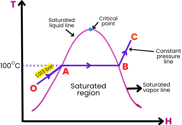
Steam Formation
Steam formation is a phase-change process in which water is converted from its liquid state to a gaseous state, which we commonly refer to as steam. This process occurs when water absorbs enough heat energy to overcome the latent heat of vaporization. Here’s a general overview of steam formation:
Application of Heat:
Steam formation begins with the application of heat to water. The heat can come from various sources, such as burning fossil fuels, nuclear reactions, or renewable energy sources like solar or geothermal.
Temperature Increase:
As heat is applied, the temperature of the water rises. At normal atmospheric pressure, water boils at 100 degrees Celsius (212 degrees Fahrenheit). However, the boiling point increases with pressure.
Boiling:
Once the water temperature reaches its boiling point at a given pressure, further application of heat does not cause a temperature increase. Instead, the absorbed heat is used to convert the water into steam.
Phase Change:
The phase change from liquid to gas involves the absorption of latent heat of vaporization. This is the energy required to break the bonds between water molecules and convert them from a liquid to a gaseous state without a change in temperature.
Steam Generation:
The resulting vapor is steam, which is composed of water vapor molecules. Steam is characterized by high energy content and the ability to do work, making it a valuable resource for various applications.
Expansion (Optional):
In some systems, steam can be further expanded or superheated, meaning its temperature is increased beyond the boiling point. This can enhance its energy content and specific properties.
The process of steam formation is a critical aspect of power generation in steam turbines. In power plants, water is heated in a boiler, and the resulting steam is directed onto turbine blades. The expansion of steam in the turbine generates mechanical energy, which is then used to turn generators and produce electricity.
It’s important to note that the conditions under which steam formation occurs, such as pressure and temperature, can influence the properties of the steam and its applications. Additionally, proper control and maintenance of steam generation systems are essential for efficient and safe operation.
Superheating
Superheating is a process in which steam is heated beyond its saturation point, which is the temperature at which it would normally boil at a given pressure. In other words, superheated steam is steam that has been further heated after reaching the boiling point and being completely vaporized.
The key characteristics of superheated steam include:
Temperature Increase: Superheated steam is at a higher temperature than the saturation temperature corresponding to its pressure. The temperature of superheated steam is often measured in degrees Celsius or Fahrenheit.
No Saturation: Unlike saturated steam, which is at the boiling point for a given pressure and contains both liquid and vapor phases, superheated steam consists entirely of vapor.
Increased Energy Content: Superheated steam carries more energy per unit mass than saturated steam at the same pressure and volume. This makes it useful for certain industrial processes and enhances its ability to do work.
The process of superheating steam is typically achieved in a separate section of a boiler or a dedicated superheater. Here’s how it generally works:
Boiling Water: The initial step involves boiling water to produce saturated steam in a boiler.
Separation: The saturated steam is then separated from any remaining water droplets, ensuring that it is in a clean, vapor state.
Superheating Section: The steam is then passed through a superheater, which is a heat exchanger designed to add more heat to the steam. This raises the temperature of the steam without changing its pressure.
Controlled Temperature: The temperature of the steam leaving the superheater can be controlled to achieve the desired level of superheat.
Superheated steam finds application in various industrial processes and power generation for several reasons:
Increased Efficiency: Superheated steam can enhance the efficiency of certain processes, particularly in power plants, where it is used to drive turbines more effectively.
Prevention of Condensation: Superheating helps prevent condensation in steam pipes, ensuring that the steam remains dry and does not lose energy through the formation of water droplets.
Improved Heat Transfer: Superheated steam can be advantageous in certain heat transfer applications where a high-temperature heat source is required.
It’s important to note that the design and use of superheaters depend on the specific requirements of the industrial or power generation process, and considerations such as safety and system efficiency play crucial roles in their implementation.
Steam Distribution
Steam distribution involves the transportation and delivery of steam from the point of generation (such as a boiler) to the points of use, where it can be utilized for various industrial, commercial, or residential applications. The efficiency and safety of steam distribution systems are essential for the successful operation of processes that rely on steam. Here are key aspects of steam distribution:
Piping System:
Steam is transported through a network of pipes from the boiler to the various points of use. The piping system must be designed to handle the high temperatures and pressures associated with steam, and it should be insulated to minimize heat loss.
Valves and Controls:
Valves are used to control the flow of steam within the distribution system. Control valves and other devices regulate the pressure, temperature, and flow rate of steam at different points to meet the specific requirements of the processes or equipment being served.
Steam Traps:
Steam traps are devices installed in the steam distribution system to remove condensate (liquid water) that forms as steam cools during transportation. Proper condensate removal is crucial for maintaining the efficiency of the system and preventing damage to equipment.
Pressure Reducing Stations:
Pressure reducing stations are often employed in steam distribution systems to reduce the pressure of high-pressure steam to a level suitable for specific applications. These stations typically include pressure-reducing valves.
Safety Devices:
Various safety devices, such as pressure relief valves, are installed to protect the steam distribution system and equipment from overpressure situations. These devices help ensure the safety of personnel and prevent damage to the system.
Steam Meters:
Steam meters are used to measure the amount of steam consumed at different points in the distribution system. This information is crucial for monitoring energy usage, optimizing system performance, and managing costs.
Condensate Return System:
Condensate, which forms when steam loses heat energy, is returned to the boiler through a condensate return system. This allows the reuse of the water and reduces the need for additional water makeup.
Insulation:
Proper insulation of steam pipes is essential to minimize heat loss and maintain the temperature of steam during transportation. Insulation materials include fiberglass, foam, or other materials suitable for high-temperature applications.
Steam Distribution in Power Plants:
In power plants, steam is distributed from the boiler to the turbines, where it is used to generate mechanical power. The high-pressure steam is then condensed back to water and returned to the boiler.
Effective steam distribution is crucial for optimizing energy efficiency, reducing operational costs, and ensuring the reliability of processes that rely on steam. Regular maintenance, monitoring, and adherence to safety standards are essential for the safe and efficient operation of steam distribution systems.
Expansion of Steam
Steam Turbines: Expansion of Steam
The expansion of steam refers to the process where steam undergoes an increase in volume as it moves from a higher pressure to a lower pressure. This expansion is a crucial part of many steam-based systems, particularly in power generation.
Here’s how the expansion of steam typically occurs in the context of a steam turbine in a power plant:
High-Pressure Steam:
Steam is generated in a boiler at high pressure and temperature. This high-pressure steam is directed towards the blades of a steam turbine.
Turbine Blades:
As the high-pressure steam flows over the blades of the turbine, it imparts its high kinetic energy to the blades, causing them to spin.
Mechanical Work:
The spinning turbine blades are connected to a shaft, and as the blades turn, they perform mechanical work on the shaft. This mechanical work is transferred to a generator, where it is converted into electrical energy.
Expansion:
As the steam passes through the turbine blades, it undergoes a significant expansion. The pressure and temperature of the steam decrease, and its volume increases. This is due to the conversion of the steam’s energy into mechanical work.
Low-Pressure Steam:
The steam exiting the turbine is now at a lower pressure and temperature. In some cases, this low-pressure steam may be directed to additional turbine stages to extract more work from the steam.
Condensation (Optional):
In certain power generation cycles, the low-pressure steam may be condensed back into water, and the water is then returned to the boiler to begin the process again.
The expansion of steam in a turbine is a key step in converting thermal energy into mechanical energy, which is then further transformed into electrical energy. The efficiency of this process is influenced by factors such as the design of the turbine, the pressure and temperature of the steam, and the overall design of the power plant.
It’s worth noting that the expansion of steam can also occur in other applications beyond power generation, such as in industrial processes where steam is used for mechanical work or heating. Understanding and controlling the expansion process are critical for optimizing the performance and efficiency of steam-based systems.
High-Pressure Steam
High-pressure steam refers to steam that is generated at a pressure significantly above atmospheric pressure. The specific pressure considered “high” can vary depending on the context, but in the realm of power generation and industrial processes, high-pressure steam is typically generated at pressures exceeding 15 psi (pounds per square inch) or 1.03 bar.
Here are key characteristics and applications of high-pressure steam:
Generation in Boilers:
High-pressure steam is often generated in specialized boilers designed to handle the higher pressures. These boilers can be found in power plants, industrial facilities, and other settings where the high-energy content of steam is required for various applications.
Power Generation:
In power plants, high-pressure steam is crucial for driving steam turbines. The expansion of high-pressure steam in turbines is used to generate mechanical work, which is then converted into electricity by generators.
Industrial Processes:
High-pressure steam is widely used in various industrial processes. Industries such as chemical, petrochemical, and manufacturing utilize high-pressure steam for tasks like sterilization, heating, and powering equipment.
Heat Transfer:
High-pressure steam is an effective medium for heat transfer due to its high energy content. It is used in heat exchangers, where it can transfer thermal energy to fluids or surfaces.
Cogeneration (Combined Heat and Power):
High-pressure steam is often employed in cogeneration systems where both electricity and useful heat are generated from the same energy source. The high-temperature steam can be used for industrial processes, and the remaining thermal energy can be converted into electricity.
District Heating:
In some district heating systems, high-pressure steam is used to distribute heat for residential and commercial heating applications.
Quality and Safety Considerations:
The quality and safety of high-pressure steam are crucial considerations. Steam at higher pressures and temperatures can cause more severe burns and injuries, and proper safety measures, including pressure relief devices, are essential.
Boiler Design:
Boilers designed for high-pressure steam must meet stringent safety and engineering standards. The construction and materials used in high-pressure boilers are carefully selected to withstand the elevated pressures and temperatures.
The selection of high-pressure steam is often driven by the specific requirements of the application. For instance, processes that demand high temperatures or high energy density may benefit from the use of high-pressure steam. However, it’s important to design and operate systems handling high-pressure steam with great care to ensure safety and efficiency. Regular maintenance, monitoring, and adherence to safety guidelines are critical aspects of managing high-pressure steam systems.
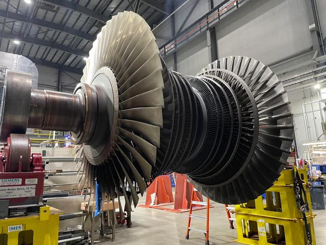
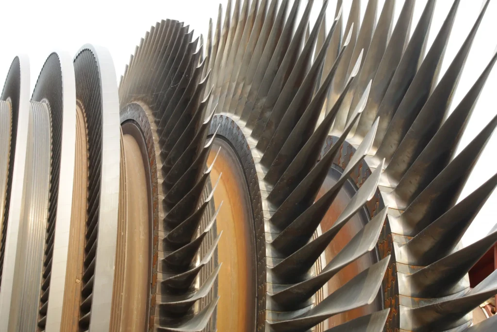
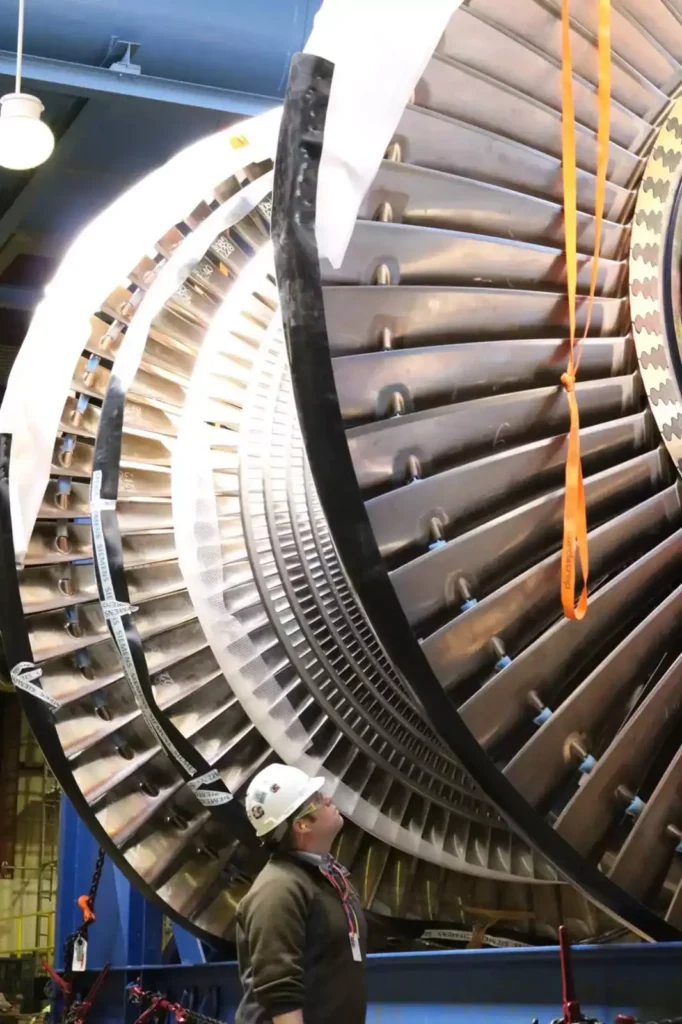
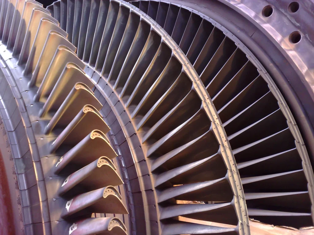
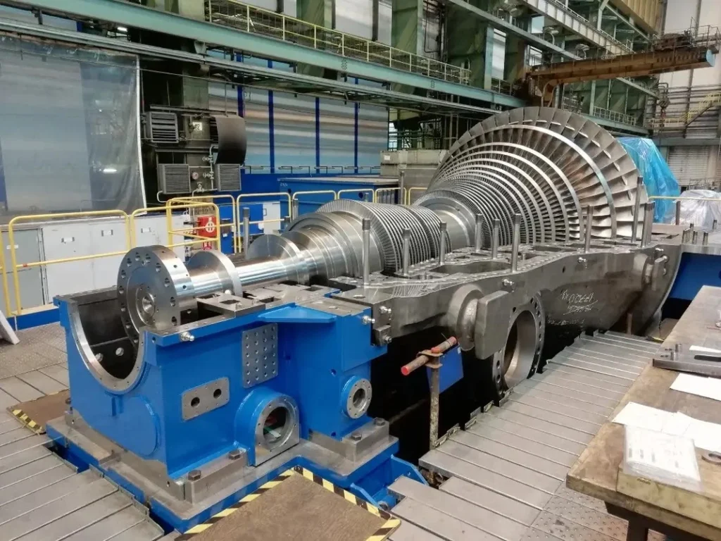
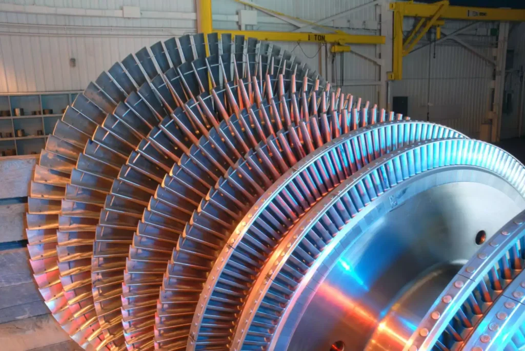
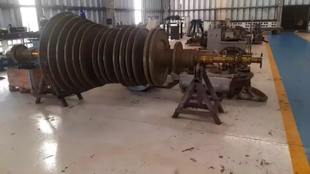
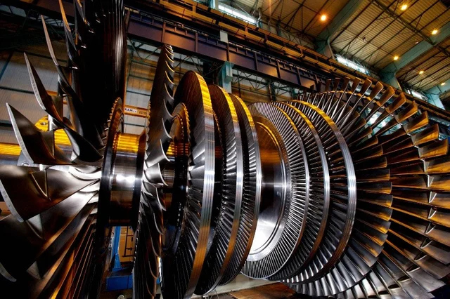
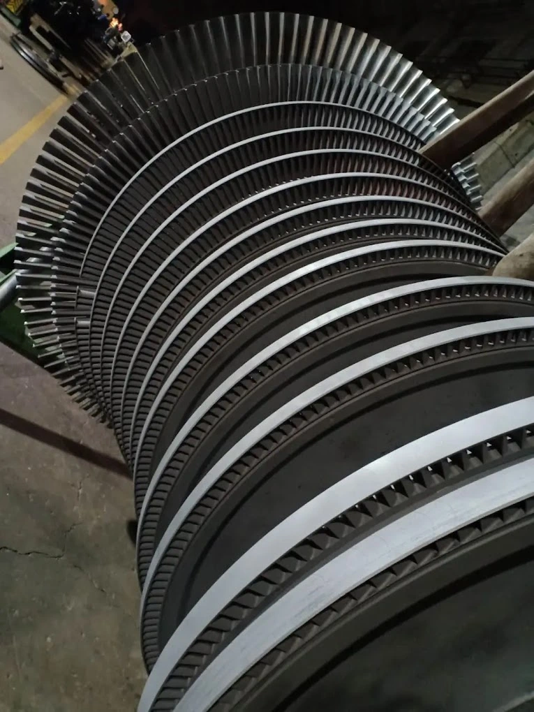
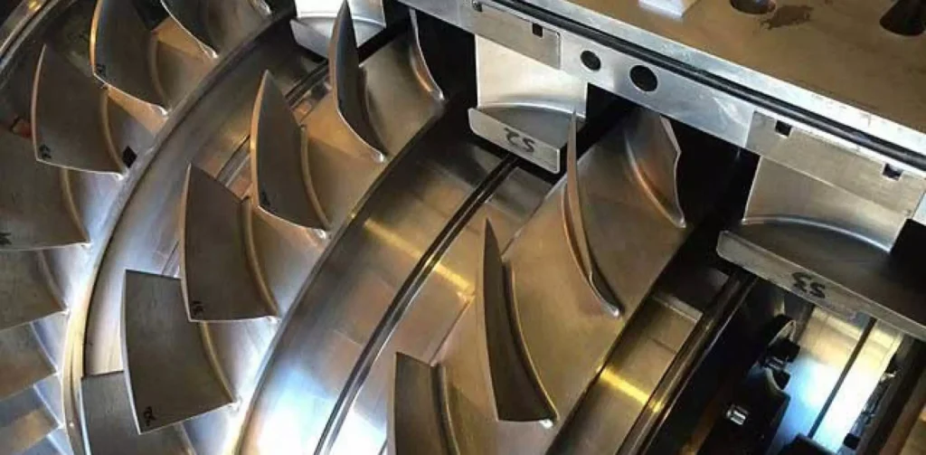
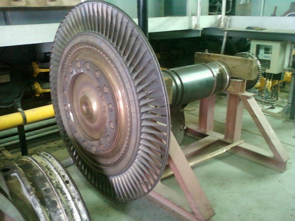
Turbine Blades
Turbine Blades
Turbine blades are a crucial component in steam turbines, gas turbines, and some types of water turbines. These blades play a key role in converting the kinetic energy of a moving fluid (steam, gas, or water) into mechanical energy that can be used to drive a generator or perform other types of work. Here’s an overview of turbine blades and their functions:
Function:
The primary function of turbine blades is to extract energy from a high-velocity fluid (steam or gas) and convert it into rotational mechanical energy. This rotational energy is then used to drive a generator or other machinery.
Types of Turbine Blades:
There are different types of turbine blades based on the specific requirements and design of the turbine. Two common types are:
Impulse Blades: These blades operate on the principle of impulse. The high-velocity fluid (steam or gas) impacts the blades, causing them to rotate.
Reaction Blades: These blades operate on the principle of both impulse and reaction. The fluid expands as it passes through the blades, causing both an impulse and a reaction force that drives the turbine.
Material and Design:
Turbine blades are typically made from high-strength materials that can withstand high temperatures and mechanical stresses. Common materials include high-alloy steels, superalloys, and advanced materials like ceramics and composites. The design of the blades is aerodynamically optimized to maximize efficiency and minimize losses.
Cooling Systems:
In gas turbines and certain steam turbines, where temperatures can reach extremely high levels, cooling systems are often integrated into the turbine blades. These systems help prevent overheating and maintain the structural integrity of the blades.
Blade Profiles:
Turbine blades have specific aerodynamic profiles designed to efficiently extract energy from the fluid. The shape of the blade is critical in maximizing the conversion of kinetic energy into mechanical energy.
Arrangement:
Turbine blades are arranged in rows, with each row designed to extract additional energy from the fluid. The arrangement may include multiple stages, each consisting of a set of rotating blades (rotor) and a set of stationary blades (stator).
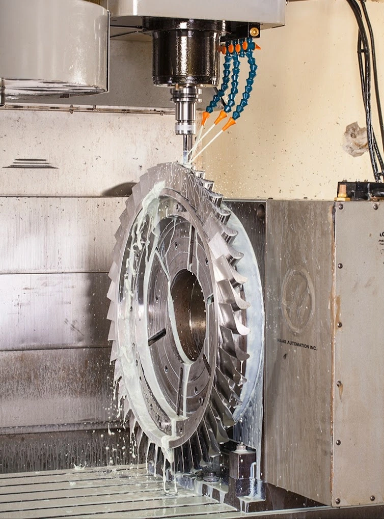
Manufacturing Processes:
Turbine blades are often manufactured using precision casting or machining techniques to achieve the required shapes and tolerances. The manufacturing process is crucial to maintaining the aerodynamic efficiency of the blades.
Maintenance:
Turbine blades undergo significant stresses during operation, and proper maintenance is essential to ensure their performance and longevity. Regular inspections, repairs, and, if necessary, replacements are part of turbine maintenance procedures.
Turbine blades are critical components in power generation, aviation, and industrial applications. The efficiency and performance of turbines depend significantly on the design, material, and condition of the blades. Advances in materials and manufacturing technologies continue to improve the efficiency and reliability of turbine blades in various applications.
Mechanical Work
The mechanical work of a steam turbine is a result of the conversion of thermal energy in the form of high-pressure, high-temperature steam into mechanical energy, which is then used to drive a generator or perform other types of mechanical work. Here’s an overview of how a steam turbine generates mechanical work:
Steam Generation:
Steam is generated in a boiler by heating water. The heat source can be various, including burning fossil fuels (coal, natural gas, oil), using nuclear reactions, or harnessing renewable energy sources.
High-Pressure Steam:
The steam produced in the boiler is at high pressure and temperature. This high-pressure steam carries a significant amount of thermal energy.
Expansion in the Turbine:
The high-pressure steam is directed into the steam turbine. As the steam flows through the turbine blades, it undergoes a process of expansion. This expansion is a key aspect of the conversion of thermal energy into mechanical energy.
Turbine Blades:
The expansion of steam causes the turbine blades to rotate. There are two main types of steam turbines based on the principles of operation: impulse turbines and reaction turbines. In impulse turbines, the high-velocity steam impacts the blades, causing them to rotate. In reaction turbines, both the velocity and pressure of the steam change as it passes through the blades, generating rotational motion.
Rotation of the Turbine Shaft:
The rotating turbine blades are connected to a shaft. As the blades turn, they impart rotational motion to the shaft.
Generator Connection:
The shaft of the turbine is connected to a generator. The mechanical rotation of the shaft is used to turn the generator rotor within a magnetic field, inducing an electric current in the generator windings.
Generation of Electricity:
The electric current generated in the generator is then transmitted through the power grid for use in homes, industries, or other applications.
Exhaust and Condensation:
After passing through the turbine, the steam is at a lower pressure and temperature. In many power plants, the steam is then directed to a condenser, where it is condensed back into water. The condensed water is returned to the boiler to be reheated and reused in the steam cycle.
The overall efficiency of a steam turbine system depends on various factors, including the design of the turbine, the quality of steam, and the control systems in place. Improvements in turbine design, materials, and control technology have led to more efficient and reliable steam turbines in power generation and industrial applications.
Expansion
Expansion, in a thermodynamic context, refers to the process by which a substance undergoes a change in volume as a result of an increase in temperature or a decrease in pressure. Expansion can occur in various states of matter, including gases, liquids, and solids. Here, I’ll briefly explain expansion in the context of gases and liquids:
Gas Expansion:
In gases, expansion is a response to an increase in temperature or a decrease in pressure. When a gas is heated, its molecules gain kinetic energy and move more rapidly, leading to an increase in pressure and volume. The relationship between pressure, volume, and temperature in a gas is described by the ideal gas law (PV = nRT), where P is pressure, V is volume, n is the number of moles of gas, R is the gas constant, and T is temperature.
For example, if you have a gas confined in a container and you heat it, the pressure inside the container will increase, and the gas will expand to occupy a larger volume.
Liquid Expansion:
In liquids, expansion primarily occurs due to an increase in temperature. When a liquid is heated, its molecules gain energy, causing them to move more vigorously and increasing the average separation between molecules. This results in an increase in the volume of the liquid.
An everyday example of liquid expansion is the expansion of water when heated. When you heat water, it expands and can lead to the rising of liquid levels in containers.
Thermal Expansion in Solids:
In solids, expansion occurs when the material is heated. This is known as thermal expansion. When a solid is heated, its molecules vibrate more rapidly, causing the material to expand. Different materials have different coefficients of thermal expansion, which describe how much they expand or contract for a given change in temperature.
The expansion and contraction of materials due to temperature changes are critical considerations in construction, engineering, and the design of structures and components.
Expansion has practical implications in various fields, and it’s important to account for these changes in real-world applications. For instance, in the design of bridges, buildings, and pipelines, engineers need to consider the potential expansion and contraction of materials due to temperature variations to prevent structural damage or failure. Similarly, the study of gas expansion is fundamental to the understanding of thermodynamics and the operation of heat engines, including steam turbines and internal combustion engines.
Low-Pressure Steam
Low-pressure steam refers to steam that is generated or used at a pressure lower than atmospheric pressure. In the context of steam, pressure is a crucial parameter that affects the temperature, density, and energy content of the steam. Low-pressure steam is often employed in various industrial, commercial, and residential applications where lower temperature and pressure conditions are suitable. Here are some key points about low-pressure steam:
Pressure Range:
While there is no strict definition for “low-pressure” steam, it generally refers to steam generated at pressures below 15 pounds per square inch (psi) or 1.03 bar. However, the specific pressure range can vary depending on the application and industry.
Applications:
Low-pressure steam has a wide range of applications, including but not limited to:
Heating Systems: Low-pressure steam is used in heating systems for space heating in buildings, particularly in older systems where steam boilers are employed.
Industrial Processes: Certain industrial processes require steam for heating, humidification, or specific manufacturing operations. Low-pressure steam can be suitable for these applications.
Food Processing: In food processing, low-pressure steam is often used for tasks like sterilization, cooking, and maintaining controlled temperatures.
Temperature and Energy Content:
Steam pressure is directly related to its temperature and energy content. Low-pressure steam will have a lower temperature compared to high-pressure steam. While it may not carry as much energy per unit volume, it can still provide sufficient heat for many applications.
Boiler Design:
Boilers designed to produce low-pressure steam may have different specifications and safety features compared to high-pressure boilers. The design considerations include maintaining the required temperature and pressure for the intended application.
Safety Considerations:
While the safety risks associated with low-pressure steam are generally lower than those with high-pressure steam, proper safety measures, including pressure relief devices and regular maintenance, are still essential to prevent accidents and ensure safe operation.
Condensate Handling:
Low-pressure steam systems often deal with condensate, which is the liquid water formed as steam gives up its latent heat. Proper handling of condensate is important for system efficiency and preventing water hammer.
Energy Efficiency:
The use of low-pressure steam in certain applications can contribute to energy efficiency, especially when the lower pressure meets the requirements of the process. It is essential to match the steam characteristics to the needs of the specific application.
Understanding the requirements and characteristics of the application is crucial when determining whether low-pressure steam is suitable. It is commonly used in systems where the energy requirements and safety considerations align with the characteristics of low-pressure steam.
Condensation
Condensation is the process by which a substance changes its physical state from a gas or vapor to a liquid. This phase transition occurs when the temperature of the substance decreases to the point where its vapor pressure equals the atmospheric pressure. Condensation is a common natural phenomenon with widespread applications in various fields. Here are key aspects of condensation:
Temperature Reduction:
Condensation occurs when a gas or vapor is cooled. As the temperature of the substance decreases, its molecular movement slows down, and the molecules come together to form a liquid.
Vapor Pressure:
The transition from a gas to a liquid during condensation is influenced by vapor pressure. Vapor pressure is the pressure exerted by a vapor when it is in equilibrium with its liquid phase. When the vapor pressure equals the atmospheric pressure, condensation occurs.
Atmospheric Conditions:
Atmospheric pressure plays a significant role in condensation. As the temperature drops, the atmospheric pressure remains relatively constant. When the vapor pressure of a substance matches the atmospheric pressure, condensation begins.
Dew Point:
The temperature at which air becomes saturated with moisture and dew or frost begins to form is known as the dew point. It represents the point at which condensation occurs in the atmosphere.
Formation of Dew:
Dew forms when moist air comes into contact with a surface that is colder than the air. The moisture in the air condenses on the cooler surface, forming water droplets.
Formation of Clouds:
In the atmosphere, condensation is a fundamental process in cloud formation. When warm, moist air rises and encounters cooler air at higher altitudes, the water vapor in the warm air condenses to form visible water droplets, leading to the creation of clouds.
Condensation in Industrial Processes:
Condensation is utilized in various industrial processes. For example, in refrigeration and air conditioning systems, a gas is compressed and then allowed to expand, leading to cooling and condensation of the refrigerant.
Applications in Heat Exchangers:
Condensation is used in heat exchangers to transfer heat from a vapor to a liquid state. This process is common in power plants, industrial processes, and HVAC systems.
Reverse Process:
The reverse of condensation is evaporation, where a liquid changes to a gas or vapor as it absorbs heat.
Prevention of Condensation:
Condensation can be managed by controlling temperature, humidity levels, and using insulation to prevent surfaces from becoming cooler than the dew point.
Understanding and controlling condensation are important in various contexts, from weather patterns and climate science to industrial processes and the design of HVAC systems. Managing condensation is crucial for preventing issues such as water damage, corrosion, and the formation of ice in different applications.
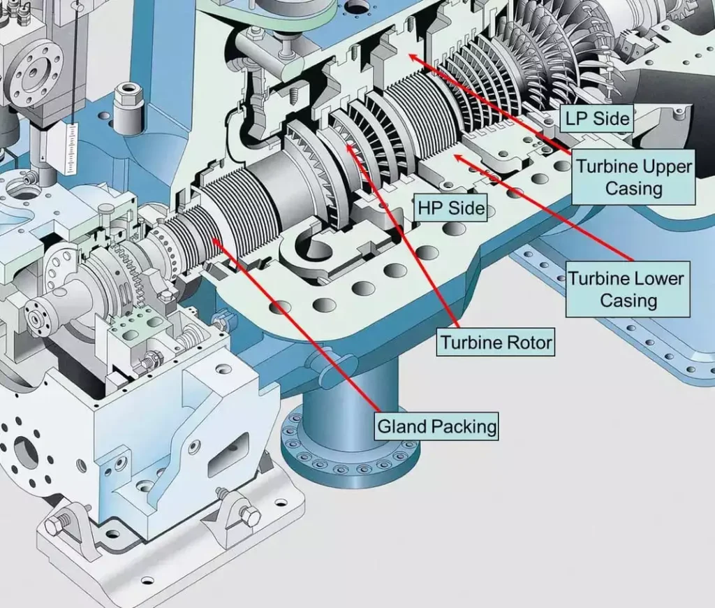
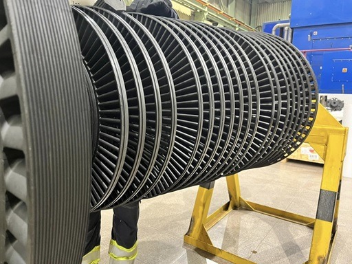
Blades and Rotors
Blades and Rotors
In the context of a steam turbine, blades and rotors are integral components that play a crucial role in the conversion of thermal energy from steam into mechanical energy. Here’s an overview of the blades and rotors in a steam turbine:
Blades
Turbine Blades:
Function: Turbine blades are the primary components responsible for extracting energy from high-pressure, high-temperature steam and converting it into mechanical energy.
Types:
Impulse Blades: Convert the kinetic energy of high-velocity steam into mechanical energy through the impact of the steam on the blades.
Reaction Blades: Operate on the principles of impulse and reaction, with steam expanding as it passes through the blades, generating both kinetic and pressure-driven forces.
Blade Profiles:
Turbine blades are designed with specific aerodynamic profiles to efficiently utilize the energy of the steam flow. The shape of the blades is critical for maximizing energy extraction and minimizing losses.
Materials:
Blades are typically made from high-strength materials capable of withstanding high temperatures and mechanical stresses. Superalloys, high-alloy steels, and advanced materials are commonly used.
Cooling Systems:
In some steam turbines, especially those in power plants where high temperatures are encountered, turbine blades may incorporate cooling systems to prevent overheating and maintain structural integrity.
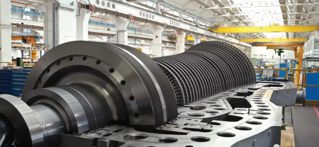
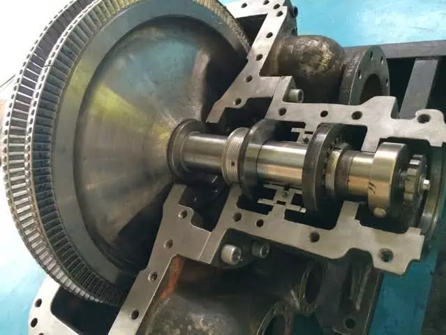
Rotors
Turbine Rotor:
Function: The rotor is the rotating component of the steam turbine to which the turbine blades are attached. It is responsible for converting the rotational motion of the blades into mechanical work.
Connection to Shaft: The rotor is connected to the shaft of the turbine. As the turbine blades rotate due to the impact of steam, the rotor, in turn, rotates, transferring mechanical energy to the shaft.
Rotor Design:
The design of the rotor is critical for the overall efficiency and performance of the steam turbine. It must be capable of withstanding the mechanical stresses induced by the rotation of the blades and the high-speed steam flow.
Bearings and Seals:
The rotor is supported by bearings that allow it to rotate smoothly. Seals are also employed to minimize steam leakage and maintain the efficiency of the turbine.
Balancing:
Proper balancing of the rotor is essential to prevent vibration and ensure the reliable and stable operation of the steam turbine. Unbalanced rotors can lead to mechanical issues and reduced efficiency.
Materials:
Rotor materials must possess high strength and fatigue resistance. The choice of materials depends on factors such as the turbine’s operating conditions and the design specifications.
The combination of turbine blades and rotor forms the core of a steam turbine, where the conversion of thermal energy to mechanical work takes place. This mechanical work is then used to drive a generator, producing electricity in power plants or performing other types of mechanical work in various industrial applications. The efficiency and reliability of the steam turbine depend significantly on the design, materials, and proper maintenance of these critical components.
Turbine Blades
Turbine Blades
Turbine blades are crucial components in turbines, which are devices that convert the energy of a moving fluid (such as steam, gas, or water) into mechanical energy. Turbines are widely used in various applications, including power generation, aviation, and industrial processes. Turbine blades play a central role in this energy conversion process. Here are key aspects of turbine blades:
Function
Energy Extraction:
Turbine blades are designed to extract energy from a high-velocity fluid (steam or gas) or from the kinetic energy of flowing water. The energy extraction results in the rotation of the turbine blades.
Mechanical Work:
As the turbine blades rotate, they perform mechanical work. This rotational motion can be used to drive a generator, produce electricity, or perform other types of mechanical work in industrial processes.
Types of Turbines:
Turbine blades are adapted to different types of turbines:
Steam Turbines: Blades in steam turbines extract energy from high-pressure, high-temperature steam.
Gas Turbines: Blades in gas turbines operate with high-velocity gases produced by combustion.
Hydraulic Turbines: Blades in hydraulic turbines extract energy from flowing water.
Characteristics
Aerodynamic Design:
Turbine blades have specific aerodynamic profiles designed to efficiently capture the energy of the fluid. The shape of the blades is critical for maximizing energy extraction and minimizing losses.
Materials:
Turbine blades are typically made from materials that can withstand high temperatures, mechanical stresses, and corrosion. Common materials include high-alloy steels, superalloys, and advanced materials like ceramics and composites.
Cooling Systems:
In applications where temperatures are extremely high, such as in gas turbines or certain sections of steam turbines, turbine blades may incorporate cooling systems to prevent overheating and maintain structural integrity.
Roots and Mounting:
The root of the turbine blade is the part that attaches to the rotor. The mounting of blades on the rotor must be robust to withstand the mechanical forces during rotation.
Types of Turbine Blades
Impulse Blades:
Impulse blades operate on the principle of converting the kinetic energy of a high-velocity fluid into mechanical energy through the impact of the fluid on the blades. These blades are common in impulse turbines.
Reaction Blades:
Reaction blades operate on the principles of both impulse and reaction. The fluid expands as it passes through the blades, generating both kinetic and pressure-driven forces. Reaction blades are often used in reaction turbines.
Maintenance
Balancing:
Proper balancing of turbine blades is essential to prevent vibration and ensure the reliable and stable operation of the turbine.
Inspections and Repairs:
Regular inspections and, if necessary, repairs or replacements of turbine blades are crucial for maintaining efficiency and preventing unexpected failures.
Turbine blades represent a critical aspect of energy conversion systems and are designed with precision to maximize efficiency and reliability in various applications. Advances in materials and design continue to improve the performance of turbine blades in modern turbines.
Blade Profile
The blade profile, also known as the airfoil profile or blade shape, refers to the cross-sectional shape of a turbine or aircraft blade as seen from the direction of fluid flow (such as air or steam). The design of the blade profile is crucial for optimizing the aerodynamic performance of the blade and, consequently, the efficiency of the entire system. Here are key aspects of blade profiles:
Characteristics
Aerodynamic Efficiency:
The primary goal of designing a specific blade profile is to achieve high aerodynamic efficiency. This involves minimizing drag, maximizing lift, and ensuring smooth airflow over the blade surface.
Lift and Drag:
The shape of the blade profile determines its ability to generate lift, which is essential for extracting energy in turbines or providing lift in aircraft. The profile is also designed to minimize drag, as excessive drag can reduce efficiency.
Angle of Attack:
The angle of attack is the angle between the chord line (a straight line connecting the leading and trailing edges of the blade) and the direction of the fluid flow. The blade profile is carefully designed to optimize the angle of attack for different operating conditions.
Chord Length:
The chord length is the distance from the leading edge to the trailing edge along the chord line. Blade profiles are characterized by their chord length and shape, which influence the overall performance of the blade.
Common Blade Profiles
NACA Airfoil Profiles:
The National Advisory Committee for Aeronautics (NACA) developed a series of airfoil profiles with systematic numbering. NACA airfoils are widely used in aviation and turbomachinery applications.
Symmetric and Asymmetric Profiles:
Some blade profiles are symmetric, meaning the upper and lower surfaces are identical. Others are asymmetric, with different shapes on the upper and lower surfaces. Asymmetric profiles are often used for specific aerodynamic requirements.
Cambered Profiles:
Camber is the curvature of the blade’s upper and lower surfaces. Cambered profiles are designed with a curve to generate lift even at zero angle of attack, enhancing overall performance.
Twisted Profiles:
In certain applications, such as aircraft propellers, blade profiles may be twisted along their length to optimize performance across different sections of the blade.
Applications
Aircraft Wings:
Aircraft wings use specific airfoil profiles to achieve lift and control. The design of the wing profiles is crucial for the aerodynamic performance of the aircraft.
Turbine Blades:
Turbine blades in steam turbines, gas turbines, or wind turbines use carefully designed profiles to efficiently extract energy from the fluid (steam, gas, or wind).
Propeller Blades:
Propeller blades in marine applications or aircraft propulsion systems use specialized profiles to generate thrust efficiently.
Fan Blades:
Fan blades in HVAC systems or industrial fans use specific profiles for optimal airflow and energy efficiency.
Computational Fluid Dynamics (CFD)
Simulation and Analysis:
Advances in Computational Fluid Dynamics (CFD) allow engineers to simulate and analyze the performance of different blade profiles under various conditions before physical prototypes are built.
The selection of a specific blade profile depends on the application, operating conditions, and desired performance characteristics. Engineers use sophisticated design and analysis tools to optimize blade profiles for specific purposes, ensuring efficiency and reliability in diverse applications.
Materials
The materials used to manufacture turbine blades are carefully chosen to withstand the harsh conditions of high temperatures, pressures, and mechanical stresses encountered in turbine applications. Different types of turbines, such as steam turbines, gas turbines, and wind turbines, may require specific materials based on their operating environments. Here are common materials used for turbine blades:
1. Superalloys
Applications: Gas Turbines, Steam Turbines
Properties:
High-temperature strength and creep resistance.
Excellent corrosion resistance.
Often contain nickel, cobalt, and other alloying elements.
Able to withstand extreme temperature differentials.
2. Single-Crystal Alloys
Applications: Gas Turbines, Aircraft Engines
Properties:
Uniform crystal structure provides superior high-temperature strength.
Enhanced resistance to thermal fatigue.
Used in the hottest sections of turbines.
3. Ceramic Matrix Composites (CMCs)
Applications: Gas Turbines, High-Temperature Environments
Properties:
Excellent thermal and chemical stability.
High strength at elevated temperatures.
Lighter weight compared to metal alloys.
Suitable for high-temperature sections of turbines.
4. Titanium Alloys
Applications: Aircraft Engines, Some Gas Turbines
Properties:
High strength-to-weight ratio.
Good corrosion resistance.
Used in sections of turbines where lower weight is crucial.
5. Nickel-Based Alloys
Applications: Gas Turbines, Steam Turbines
Properties:
Good high-temperature strength.
Corrosion-resistant.
Suitable for high-pressure and high-temperature sections of turbines.
6. Coating Materials
Applications: Gas Turbines, Steam Turbines
Properties:
Thermal barrier coatings (TBCs) protect against high temperatures.
Oxidation-resistant coatings extend the lifespan of the blades.
Coatings can be applied to enhance durability and performance.
7. Composite Materials
Applications: Wind Turbines
Properties:
Fiberglass, carbon fiber, or hybrid composites are used.
High strength, low weight, and resistance to fatigue.
Commonly used in the construction of blades for wind turbines.
8. High-Strength Steels
Applications: Some Industrial Turbines
Properties:
High strength and toughness.
Used in applications where high-temperature resistance is not the primary concern.
Considerations for Material Selection
Temperature and Pressure:
Materials must withstand the high temperatures and pressures specific to the operating conditions of the turbine.
Corrosion Resistance:
Corrosion-resistant materials are crucial, especially in steam turbines where moisture is present.
Fatigue Resistance:
Turbine blades experience cyclic loading, and materials must be fatigue-resistant to ensure long-term reliability.
Weight Considerations:
In aircraft engines and some gas turbines, lightweight materials such as titanium alloys are preferred to reduce weight and improve fuel efficiency.
Manufacturing Processes:
The manufacturing processes for turbine blades, such as casting or precision machining, may influence material selection.
Advancements in Materials:
Ongoing research and advancements in materials science lead to the development of new alloys and composites with improved properties.
The selection of materials for turbine blades is a critical aspect of turbine design, ensuring that the blades can withstand the extreme conditions and provide reliable and efficient performance over their operational lifespan.
Mechanical Work
The mechanical work of a steam turbine involves the conversion of thermal energy carried by high-pressure, high-temperature steam into rotational mechanical energy. This mechanical energy is then utilized to drive a generator, producing electricity or perform other types of mechanical work. The process of how a steam turbine generates mechanical work can be broken down into several key steps:
Steam Generation:
Steam is generated in a boiler by heating water using a heat source. This heat source can come from burning fossil fuels (coal, natural gas, oil), nuclear reactions, or other sources.
High-Pressure Steam:
The steam produced in the boiler is at high pressure and temperature. This high-pressure steam contains a significant amount of thermal energy.
Expansion in the Turbine:
The high-pressure steam is directed into the steam turbine. As the steam flows through the turbine blades, it undergoes a process of expansion. This expansion is essential for converting the thermal energy of the steam into mechanical energy.
Turbine Blades:
The expansion of steam causes the turbine blades to rotate. There are two main types of steam turbines based on the principles of operation: impulse turbines and reaction turbines. Impulse turbines utilize the impact of high-velocity steam on the blades, while reaction turbines operate on both impulse and reaction forces as steam expands through the blades.
Rotation of the Turbine Shaft:
The rotating turbine blades are connected to a shaft. As the blades turn, they impart rotational motion to the shaft.
Generator Connection:
The shaft of the turbine is connected to a generator. The mechanical rotation of the shaft is used to turn the generator rotor within a magnetic field, inducing an electric current in the generator windings.
Generation of Electricity:
The electric current generated in the generator is then transmitted through the power grid for use in homes, industries, or other applications.
Exhaust and Condensation:
After passing through the turbine, the steam is at a lower pressure and temperature. In many power plants, the steam is then directed to a condenser, where it is condensed back into water. The condensed water is returned to the boiler to be reheated and reused in the steam cycle.
The overall efficiency of a steam turbine system depends on various factors, including the design of the turbine, the quality of steam, and the control systems in place. Improvements in turbine design, materials, and control technology have led to more efficient and reliable steam turbines in power generation and industrial applications. The mechanical work generated by steam turbines is a fundamental aspect of converting heat into useful energy for various applications.
Exhaust
In the context of a steam turbine or any heat engine, the term “exhaust” refers to the outlet or discharge of the working fluid (steam, gas, or air) after it has passed through the turbine and performed work. The exhaust stage is a crucial part of the thermodynamic cycle, as it completes the energy conversion process and prepares the working fluid for the next cycle. Here are key points related to the exhaust stage:
Lower Pressure and Temperature:
As the working fluid passes through the turbine and performs mechanical work, its pressure and temperature decrease. By the time the fluid reaches the exhaust stage, it is at a lower pressure and temperature compared to its state before entering the turbine.
Exit Velocity:
The fluid leaving the turbine at the exhaust stage often has a significant velocity. This is a result of the expansion of the fluid as it passes through the turbine blades. The high-speed exhaust flow can be harnessed for certain applications, such as jet propulsion or wind power.
Condensation (Steam Turbines):
In steam turbines, the exhaust steam is typically directed to a condenser. The condenser is a heat exchanger that removes heat from the steam, causing it to condense back into liquid water. This condensed water is then returned to the boiler for reheating, completing the steam cycle.
Recompression (Gas Turbines):
In gas turbines, the exhaust gases may be directed to a device called a compressor. The compressor compresses the exhaust gases before they are released into the atmosphere. This recompression can enhance the overall efficiency of the gas turbine system.
Environmental Considerations:
The composition of the exhaust (such as in the case of gas turbines) is of environmental concern. The emissions from the exhaust may include pollutants, and efforts are made to minimize environmental impact through technologies like exhaust gas treatment systems.
Jet Propulsion:
In the context of jet engines, the exhaust is expelled at high speed to generate thrust. This is essential for propelling aircraft and other vehicles.
Waste Heat Recovery:
Some systems incorporate waste heat recovery from the exhaust to improve overall efficiency. Heat exchangers may be used to capture and utilize the thermal energy in the exhaust for other processes.
Cyclic Process:
The exhaust stage marks the completion of one cycle in the thermodynamic process. The working fluid, having given up some of its energy to perform work, is ready to be reintroduced into the system to begin a new cycle.
Understanding and optimizing the exhaust stage are crucial for maximizing the efficiency of a heat engine or turbine system. The design considerations for the exhaust depend on the specific application, whether it be power generation, propulsion, or industrial processes.
It’s worth noting that there are various types of boilers, each with its own design and application. The choice of boiler type depends on factors such as the intended use of steam, fuel availability, and efficiency considerations.
Steam generation is a fundamental process in many industries and plays a crucial role in power generation, manufacturing, and heating applications worldwide.
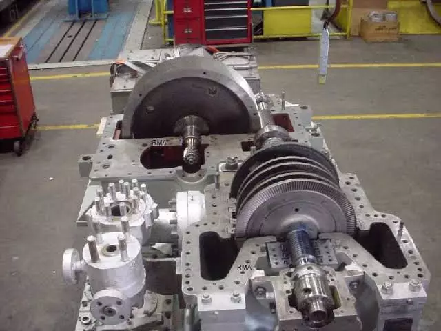
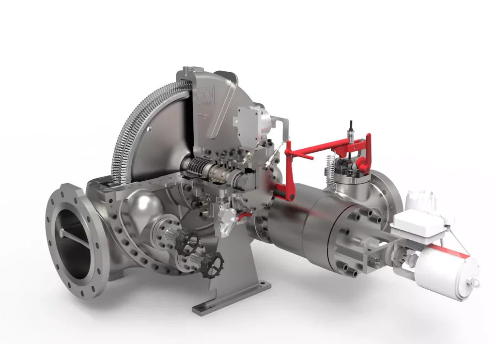
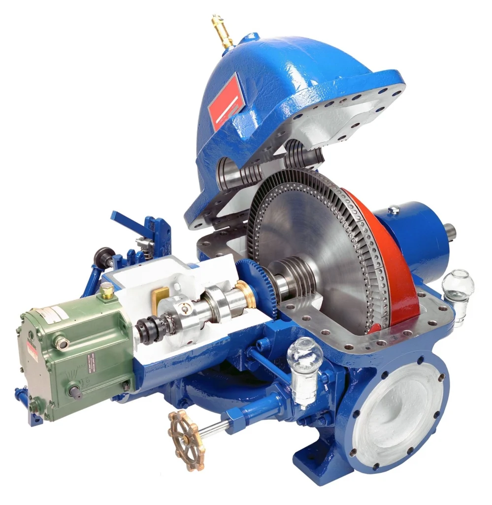
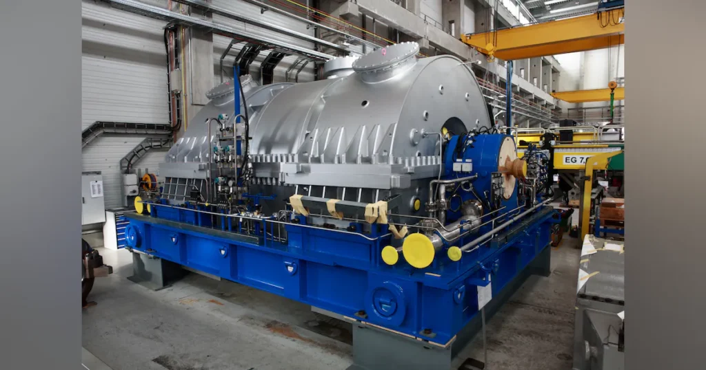
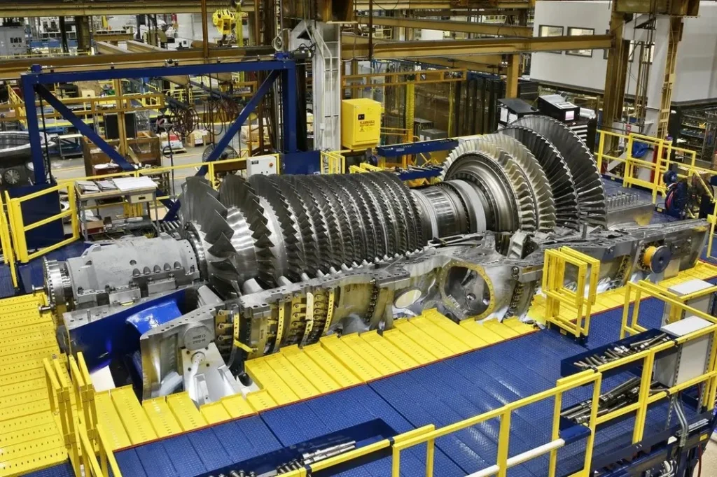
Types of Steam Turbines
Types of Steam Turbines
There are different types of steam turbines, including:
Impulse Turbines: These turbines operate based on the principle of impulse, where high-velocity jets of steam are directed onto the turbine blades.
Reaction Turbines: These turbines operate on the principle of both impulse and reaction, with steam expanding both as it passes over the blades and as it expands through them.
Steam turbines are crucial components in power plants, where they are often used in conjunction with other systems to generate electricity. They have been a key technology for power generation for over a century and continue to play a significant role in the production of electricity worldwide.
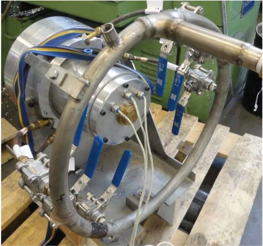
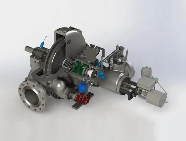
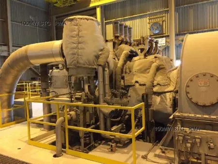
Small sized steam turbines are used in a variety of applications ranging from power generation in small-scale power plants to mechanical drives in industrial equipment. A steam turbine is a machine that converts thermal energy from steam into mechanical energy. Small sized steam turbines typically generate power in the range of a few kilowatts to several megawatts.
The design of small sized steam turbines typically involves several stages of blades that expand steam to create rotational force. The steam turbine rotor is typically mounted on bearings and rotates on a shaft. The steam is fed into the turbine through nozzles and directed onto the blades, causing the rotor to spin. The rotational force is transferred to a generator or other equipment to produce electricity or mechanical power.
Small sized steam turbines are used in various industries, including food processing, chemical, and pharmaceutical industries. They are used to power various machines and equipment, such as pumps, compressors, and fans. They are also used for combined heat and power (CHP) applications, where steam generated by a boiler is used to drive a steam turbine and produce both electricity and heat for industrial processes.
Steam Turbine Advantages
Steam Turbine Advantages
Advantages of small sized steam turbines include their high efficiency and reliability. They can also operate on a variety of fuels, including coal, oil, and natural gas. Additionally, small sized steam turbines can be designed to operate at varying loads, making them suitable for use in a wide range of applications.
However, there are also some disadvantages to using small sized steam turbines. They require regular maintenance to ensure optimal performance and can be expensive to operate and maintain. Additionally, the initial capital cost of a steam turbine can be high.
In summary, small sized steam turbines are an important source of power and mechanical energy in various industries. They offer high efficiency and reliability, making them suitable for a wide range of applications. However, they require regular maintenance and can be expensive to operate and maintain.
Dependability and versatility of equipment are vital to today’s process plants, pharmaceutical producers, mining interests, and a host of other users including, of course, petroleum, petrochemical, and chemical-process industries.
Operating pressures and temperatures are constantly rising; single-train capacities grow by leaps and bounds; continuity of service becomes a vital force, and the economy demands longer and longer periods between overhauls. Steam turbines are faithful partners to the process industries. They have proved their basic reliability and today are showing a new versatility by keeping pace with every demand for higher capacity, speed, and reliability.
Wherever you look in the process industries, there are more mechanical drive turbines; wherever you look, both horsepower and speed go up, year after year. And wherever you look, technological advances are being incorporated into modern steam turbines. Many manufacturers deserve to be recognized for their ability to solve the tougher steam turbine application problems.
Through advanced planning, imaginative research, persistent development, and painstaking evaluation, engineers have in the last quarter of this century created a whole new turbine generation: machines of sizes and speeds that were only dreamed of a few decades ago. Multiflow exhausts, solid rotors, highspeed bearings, taller last-stage blades (“buckets”), cam-operated valve gear and controls, and other highly sophisticated control systems and computerized designs are a few of the innovations that helped make this progress
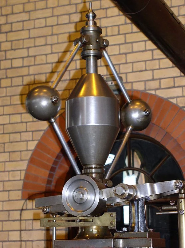
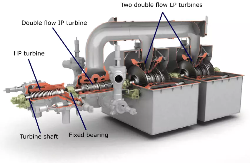
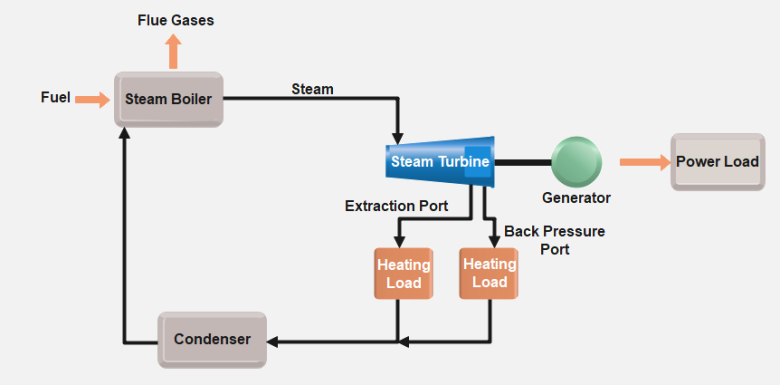
Knowledgeable manufacturers have available a wide selection of steam end designs, either single or multivalve, to meet any specific pressure and temperature conditions. The overwhelming majority of cases both industrial and cogeneration systems designed for electric power generation uses a simple, single-casing steam turbine. These turbines (Fig. 1.1) can be designed to provide operating flexibility to economically utilize steam from a variety of sources to supply:
Direct or geared power input for compressors, pumps, or other driven equipment
Steam at the pressures and quantities required for integrated processes or lower-pressure turbines
The electric power desired
Cogenerated power for sale to the local utility
Overview of Steam Turbine Fundamentals
Steam Turbine
Before discussing turbine selection, let’s review how a steam turbine converts the heat energy of steam into useful work. The nozzles and diaphragms in a turbine are designed to direct the steam flow into well-formed, high-speed jets as the steam expands from inlet to exhaust pressure. These jets strike moving rows of blades mounted on the rotor. The blades convert the kinetic energy of the steam into the rotation energy of the shaft.
There are two principal turbine types: reaction and impulse. In a reaction turbine, the steam expands in both the stationary and moving blades. The moving blades are designed to utilize the steam jet energy of the stationary blades and to act as nozzles themselves. Because they are moving nozzles, a reaction force—produced by the pressure drop across them—supplements the steam jet force of the stationary blades. These combined forces cause rotation.
To operate efficiently the reaction turbine must be designed to minimize leakage around the moving blades. This is done by making most internal clearances relatively small. The reaction turbine also usually requires a balance piston (similar to those used in large centrifugal compressors) because of the large thrust loads generated. Because of these considerations, the reaction turbine is seldom used for mechanical drive in the United States, despite its occasionally higher initial efficiency. Reaction turbines are, nevertheless, in widespread use in Europe and the rest of the world.
They deserve to be discussed and will be dealt with later. The impulse turbine has little or no pressure drop across its moving blades. Steam energy is transferred to the rotor entirely by the steam jets striking the moving blades
Steam Turbine Description and Components
A steam turbine is a device that converts thermal energy from pressurized steam into mechanical work, which can then be used to generate electricity or perform other mechanical tasks. It is a type of heat engine that operates on the principle of converting the energy contained in high-pressure steam into rotational motion.
The basic components of a steam turbine include:
Rotor: The rotor is the rotating part of the turbine that converts the steam’s kinetic energy into mechanical work. It typically consists of multiple blades or buckets attached to a central shaft.
Stator: The stator is the stationary part of the turbine that contains fixed blades or nozzles. It guides the flow of steam onto the rotor blades, providing the necessary direction and control.
Steam Inlet: The steam inlet is where high-pressure steam enters the turbine. It is connected to a steam source, such as a boiler, and the steam is directed into the turbine for expansion.
Exhaust Outlet: The exhaust outlet is where the low-pressure steam exits the turbine after performing work. It is usually connected to a condenser or other steam utilization system.
Governor: The governor is a control mechanism that regulates the steam flow and maintains a constant speed of the turbine, ensuring stable operation.
Steam turbines are commonly used in power plants to generate electricity. They can be categorized into different types based on their design and operational characteristics, such as condensing or non-condensing turbines, impulse or reaction turbines, and single-stage or multi-stage turbines.
The efficiency of a steam turbine depends on various factors, including the steam pressure and temperature, turbine design, and operating conditions. Steam turbines can achieve high efficiency levels, especially in combined cycle power plants where waste heat from the turbine is recovered and used to generate additional power.
Overall, steam turbines have been widely used for power generation due to their reliability, scalability, and ability to utilize a variety of fuel sources, including fossil fuels and renewable energy sources such as biomass or geothermal steam.
Rotor
Rotor
The rotor is a crucial component of a steam turbine. It is the rotating part of the turbine that converts the kinetic energy of the steam into mechanical work. The rotor typically consists of a central shaft and multiple blades or buckets attached to it.
The main function of the rotor is to extract energy from the high-pressure and high-temperature steam flowing through the turbine. As the steam passes over the blades, it imparts a force on them, causing the rotor to rotate. The rotation of the rotor is what generates the mechanical work that can be used for various applications, such as generating electricity in a power plant or driving industrial machinery.
The design and construction of the rotor are critical to ensure efficient and reliable operation of the steam turbine. The blades or buckets are shaped in a way that optimizes the flow of steam and maximizes the energy transfer. They are carefully engineered to withstand high temperatures, pressures, and centrifugal forces.
Depending on the type and size of the steam turbine, the rotor can have different configurations. In impulse turbines, the blades are arranged in a radial or axial configuration, and the steam acts on them in discrete stages. In reaction turbines, the blades are shaped to react to the steam continuously as it passes over them.
The rotor is connected to the generator or the mechanical load being driven by the turbine. The rotational motion of the rotor is transmitted to the generator or load through a coupling or a gearbox, where it is converted into electrical power or mechanical work, respectively.
Efficient and well-designed rotors are essential for the overall performance and output of a steam turbine. They undergo rigorous engineering analysis and testing to ensure they can withstand the operating conditions and deliver the desired power output while maintaining reliability and durability.
Stator
The stator is another important component of a steam turbine. It is the stationary part of the turbine that surrounds the rotor. The stator is responsible for directing and controlling the flow of steam as it passes through the turbine, converting the kinetic energy of the steam into mechanical work.
The primary function of the stator is to house the stationary blades or vanes that guide the flow of steam onto the rotor blades. These stationary blades are designed to optimize the flow of steam, ensuring efficient energy transfer and maximum power output. The stator blades are typically curved or angled to direct the steam in the desired direction and maintain a uniform flow.
In addition to guiding the steam flow, the stator also serves to support and protect the rotor and other internal components of the turbine. It provides structural stability and helps maintain the alignment of the rotor and stator blades.
The stator is typically constructed using high-quality materials that can withstand the high temperatures, pressures, and mechanical stresses encountered in the steam turbine. It is often made of steel or other alloys with excellent heat resistance and mechanical properties.
In large steam turbines, the stator is composed of multiple sections or stages, each with its set of stationary blades. These stages are designed to progressively extract energy from the steam as it passes through the turbine, improving the overall efficiency of the system.
The stator is an integral part of the steam turbine, working in conjunction with the rotor to convert steam energy into mechanical work. Together, they form a highly efficient and reliable power generation system used in various industries, including power plants, refineries, and industrial processes.
Steam Inlet
The steam inlet, also known as the steam admission or steam entry, is the point of entry for high-pressure steam into the steam turbine. It is a crucial component that allows the steam to enter the turbine and initiate the power generation process.
The steam inlet is typically located on the outer casing of the turbine and is connected to the steam source, such as a boiler or steam generator. The high-pressure steam flows through the steam inlet and enters the turbine at a specific angle and velocity.
To ensure efficient and controlled entry of steam into the turbine, the steam inlet is designed with various features. These include:
Nozzles: The steam inlet may have a set of nozzles or guide vanes that help control the flow direction and velocity of the steam entering the turbine. These nozzles are adjustable and can be positioned to optimize the steam flow for maximum efficiency.
Steam Strainers: Steam strainers or filters are sometimes installed at the steam inlet to remove any solid particles or impurities from the steam. These strainers help protect the turbine blades from damage and ensure smooth operation.
Steam Control Valves: Steam control valves are often installed at the steam inlet to regulate the flow of steam into the turbine. These valves can adjust the steam flow rate and pressure, allowing for precise control of the turbine’s power output.
Expansion Joints: Expansion joints are used at the steam inlet to accommodate thermal expansion and contraction of the turbine components. They help maintain the integrity of the turbine casing while allowing for the necessary movement caused by temperature variations.
The design and configuration of the steam inlet may vary depending on the specific type and size of the steam turbine. The goal is to ensure efficient steam flow, minimize pressure losses, and protect the turbine from any potential damage.
Overall, the steam inlet plays a critical role in the steam turbine’s operation by allowing high-pressure steam to enter the turbine and initiate the energy conversion process. Its design and functionality are crucial for optimizing turbine performance and ensuring reliable power generation.
Exhaust Outlet
The exhaust outlet, also known as the exhaust nozzle or exhaust diffuser, is the point of exit for the steam or gas after it has passed through the turbine and performed its work. It is an essential component of a steam turbine system as it allows the spent steam or gas to be discharged safely and efficiently.
The exhaust outlet is typically located at the opposite end of the turbine from the steam or gas inlet. It is designed to convert the high-velocity, high-pressure steam or gas into a lower-velocity, lower-pressure state before it is released into the surrounding environment or directed to further use, such as for heating or industrial processes.
The exhaust outlet performs several important functions:
Pressure Reduction: The exhaust outlet is designed to gradually decrease the pressure of the steam or gas as it expands and flows through the turbine. This pressure reduction allows the steam or gas to exit the turbine at a lower pressure, minimizing the risk of sudden pressure changes that could damage the turbine or associated equipment.
Velocity Control: The exhaust outlet helps control the velocity of the exhaust steam or gas as it exits the turbine. By gradually increasing the cross-sectional area of the outlet, the steam or gas velocity is reduced, which helps to minimize noise and prevent any potential damage to downstream components.
Energy Recovery: In some cases, the exhaust outlet may be connected to a heat recovery system or condenser. This allows for the extraction of additional energy from the exhaust steam or gas by recovering heat or converting it into usable power. This improves the overall efficiency of the turbine system.
Noise Reduction: The design of the exhaust outlet may incorporate features such as diffusers or silencers to reduce noise generated by the high-velocity exhaust steam or gas. This helps to meet noise regulations and maintain a quieter operating environment.
The specific design and configuration of the exhaust outlet may vary depending on the size, type, and application of the steam turbine. Factors such as exhaust pressure, flow rate, and temperature are considered in the design to optimize turbine performance and ensure safe operation.
Overall, the exhaust outlet is a critical component of a steam turbine system, responsible for safely and efficiently discharging the spent steam or gas. Its design aims to control pressure, velocity, and noise while allowing for energy recovery when applicable.
Governor of the Steam Turbine
The governor is an important control device used in steam turbines to regulate the speed and output power of the turbine. Its main function is to maintain a constant rotational speed of the turbine within a desired range, regardless of changes in the load or steam conditions.
The governor operates based on the principle of feedback control, where it continuously monitors the speed of the turbine and adjusts the steam flow to maintain the desired speed. Here’s a brief overview of how the governor works:
Speed Sensing: The governor is equipped with speed-sensing mechanisms such as centrifugal weights or magnetic pickups that detect the rotational speed of the turbine. These sensors provide input signals to the governor control system.
Control System: The governor control system processes the speed signals and compares them to the desired speed setpoint. It calculates the error between the actual speed and the setpoint and determines the necessary adjustments to be made.
Steam Flow Regulation: Based on the error signal, the governor control system adjusts the steam flow rate entering the turbine. This is typically achieved by modulating the steam control valves that regulate the steam flow. If the turbine speed is below the setpoint, the governor increases the steam flow, and if the speed is above the setpoint, it decreases the steam flow.
Feedback Loop: The governor continuously monitors the turbine speed and makes ongoing adjustments to the steam flow to maintain the desired speed. It operates in a closed-loop feedback system, where it compares the measured speed with the setpoint and adjusts the steam flow accordingly.
The governor ensures stable operation of the steam turbine by responding to changes in load demand and maintaining a constant speed. It helps to prevent overspeed or underspeed conditions that could potentially damage the turbine or cause operational issues. Additionally, the governor provides a means of controlling the output power of the turbine, allowing it to respond to changes in the electrical grid or other power system requirements.
Modern steam turbines often utilize advanced electronic or digital governor systems that offer more precise control and flexibility. These systems may incorporate additional features such as load sharing between multiple turbines, protection functions, and communication interfaces for integration into broader control systems.
Overall, the governor plays a crucial role in the safe and efficient operation of steam turbines by regulating the turbine speed and power output to meet the desired operating conditions.
Steam Turbine Application Areas
Steam Turbine Application Areas
Steam turbines are used in a wide variety of applications, including:
Power generation: Steam turbines are the most common type of prime mover used in power plants to generate electricity. They are also used in combined heat and power (CHP) plants to generate both electricity and heat.
Industrial processes: Steam turbines are used in a variety of industrial processes, such as oil refining, chemical processing, and papermaking. They are used to drive compressors, pumps, and other machinery.
Marine propulsion: Steam turbines are used to power large ships, such as aircraft carriers and cruise ships.
Transportation: Steam turbines are used to power some locomotives and other rail vehicles.
Here are some specific examples of how steam turbines are used in different industries:
Power generation: In the power generation industry, steam turbines are used to drive generators to produce electricity. The steam is typically generated by a boiler, which is heated by burning fossil fuels or nuclear fuel. The steam then drives the turbine blades, which rotate the generator shaft. The generator shaft is connected to a rotor, which generates electricity as it rotates.
Industrial processes: In the industrial process industry, steam turbines are used to drive a variety of machinery, such as compressors, pumps, and fans. Steam turbines are also used to generate heat for industrial processes, such as drying products and distilling liquids.
Marine propulsion: In the marine propulsion industry, steam turbines are used to power large ships, such as aircraft carriers and cruise ships. The steam turbines drive propellers, which propel the ship through the water.
Transportation: In the transportation industry, steam turbines are used to power some locomotives and other rail vehicles. Steam turbines are also used to power some electric power plants that are built on trains.
Steam turbines are a versatile and efficient type of prime mover that can be used in a wide variety of applications. They are a key component of the global energy infrastructure.
Power Generation with Steam Turbines
Power Generation with Steam Turbines
Steam turbines are used to generate electricity in power plants by converting the thermal energy of steam into mechanical energy. The steam is generated in a boiler by heating water with fossil fuels, nuclear fuel, or renewable energy sources such as solar or geothermal energy. The high-pressure steam is then fed to the steam turbine, where it expands and drives the turbine blades. The turbine blades are connected to a shaft, which rotates a generator to produce electricity.
There are two main types of steam turbines used in power generation:
Condensing steam turbines: Condensing steam turbines are the most common type of steam turbine used in power plants. They operate by condensing the steam that exits the turbine back into water. This allows the turbine to operate at a higher efficiency.
Backpressure steam turbines: Backpressure steam turbines are used in combined heat and power (CHP) plants to generate both electricity and heat. They operate by extracting some of the steam from the turbine before it is fully expanded. This steam is then used to provide heat for industrial processes or buildings.
Steam turbines are an efficient and reliable way to generate electricity. They are also very versatile and can be used to generate electricity from a variety of energy sources.
Boiler: The boiler heats water to generate steam.
Superheater: The superheater heats the steam to a higher temperature.
Reheater: The reheater heats the steam after it has expanded through the high-pressure turbine.
High-pressure turbine: The high-pressure turbine extracts some of the energy from the steam.
Low-pressure turbine: The low-pressure turbine extracts the remaining energy from the steam.
Condenser: The condenser condenses the steam back into water.
Feedwater pump: The feedwater pump pumps the condensed water back to the boiler.
Generator: The generator converts the mechanical energy of the turbine shaft into electricity.
Steam turbines play a vital role in the global energy infrastructure. They are a key component of the transition to a clean energy future, as they can be used to generate electricity from a variety of renewable energy sources.
Industrial Processes where Steam Turbine is Used
Steam turbines are used in a wide variety of industrial processes, including:
Oil refining: Steam turbines are used to drive compressors, pumps, and other machinery in oil refineries. They are also used to generate heat for distillation processes.
Chemical processing: Steam turbines are used to drive compressors, pumps, and other machinery in chemical plants. They are also used to generate heat for chemical reactions.
Papermaking: Steam turbines are used to drive machinery in paper mills, such as pulpers, paper machines, and dryers. They are also used to generate heat for drying paper.
Food and beverage processing: Steam turbines are used to drive machinery in food and beverage processing plants, such as conveyors, mixers, and cookers. They are also used to generate heat for sterilization and pasteurization processes.
Textile manufacturing: Steam turbines are used to drive machinery in textile mills, such as spinners, weavers, and finishers. They are also used to generate heat for drying and dyeing textiles.
Metalworking: Steam turbines are used to drive machinery in metalworking shops, such as rolling mills, presses, and saws. They are also used to generate heat for heat treatment processes.
Here are some specific examples of how steam turbines are used in different industrial processes:
Oil refining: In the oil refining industry, steam turbines are used to drive compressors that compress crude oil to high pressures. The compressed oil is then fed to distillation columns, where it is separated into different fractions, such as gasoline, diesel fuel, and jet fuel. Steam turbines are also used to drive pumps that circulate oil through the refinery and to generate heat for distillation processes.
Chemical processing: In the chemical processing industry, steam turbines are used to drive compressors that compress gases, such as air, nitrogen, and hydrogen. The compressed gases are then used in a variety of chemical processes, such as ammonia production and fertilizer manufacturing. Steam turbines are also used to drive pumps and mixers, and to generate heat for chemical reactions.
Papermaking: In the papermaking industry, steam turbines are used to drive pulpers that break down wood chips into fibers. The fibers are then mixed with water and chemicals to form a slurry, which is then fed to a paper machine. The paper machine forms the slurry into a sheet of paper, which is then dried and finished. Steam turbines are used to drive all of the machinery in a paper mill, as well as to generate heat for drying paper.
Food and beverage processing: In the food and beverage processing industry, steam turbines are used to drive conveyors that transport food and beverage products through the processing plant. They are also used to drive mixers and cookers, and to generate heat for sterilization and pasteurization processes.
Textile manufacturing: In the textile manufacturing industry, steam turbines are used to drive spinners that spin yarn from fibers. The yarn is then fed to a weaver to create fabric, which is then finished. Steam turbines are used to drive all of the machinery in a textile mill, as well as to generate heat for drying and dyeing textiles.
Metalworking: In the metalworking industry, steam turbines are used to drive rolling mills that roll metal sheets and plates into different shapes. They are also used to drive presses that punch or stamp metal parts, and saws that cut metal. Steam turbines are used to drive all of the machinery in a metalworking shop, as well as to generate heat for heat treatment processes.
Steam turbines are an essential part of many industrial processes. They provide a reliable and efficient way to power machinery and generate heat.
Marine propulsion with Steam Turbines
Steam turbines have been used for marine propulsion for over a century. They were the dominant form of marine propulsion in the early 20th century, but they have since been largely replaced by diesel engines. However, steam turbines are still used in some large ships, such as aircraft carriers and cruise ships.
Steam turbines are a good choice for marine propulsion because they are efficient and reliable. They can also be used to generate a lot of power, which is needed for large ships. However, steam turbines are also complex and expensive to build and maintain.
Boiler: The boiler heats water to generate steam.
Superheater: The superheater heats the steam to a higher temperature.
Reheater: The reheater heats the steam after it has expanded through the high-pressure turbine.
High-pressure turbine: The high-pressure turbine extracts some of the energy from the steam.
Low-pressure turbine: The low-pressure turbine extracts the remaining energy from the steam.
Condenser: The condenser condenses the steam back into water.
Feedwater pump: The feedwater pump pumps the condensed water back to the boiler.
Propeller: The propeller is driven by the turbine shaft and propels the ship through the water.
Steam turbine propulsion systems are typically used in large ships, such as aircraft carriers and cruise ships. These ships need a lot of power to propel them through the water, and steam turbines can provide that power.
Steam turbines are also used in some submarines. Submarines need to be able to operate quietly, and steam turbines can be operated very quietly. This is important because it allows submarines to avoid detection.
Overall, steam turbines are a good choice for marine propulsion because they are efficient, reliable, and can generate a lot of power. However, they are also complex and expensive to build and maintain.
Steam Turbines
Steam Turbines
Steam turbines are a fundamental component of modern power generation and various industrial processes. They convert thermal energy from steam into mechanical energy, which can then be used to generate electricity or drive machinery. The concept of harnessing steam power dates back to ancient times, with early attempts to use steam for mechanical purposes seen in the aeolipile, a simple steam-powered device invented by Hero of Alexandria in the 1st century AD. However, it wasn’t until the 19th century that steam turbines, as we know them today, began to take shape.
The breakthrough in steam turbine technology came in the late 19th century with the work of Sir Charles Parsons and Gustaf de Laval. Sir Charles Parsons is often credited with inventing the modern steam turbine in 1884, when he developed a prototype capable of driving an electrical generator. This invention marked a significant leap in efficiency compared to earlier steam engines. Parsons’ steam turbine quickly became the preferred method for generating electricity, and its design principles are still used in modern turbines.
Gustaf de Laval, a Swedish engineer, made significant contributions to the development of steam turbines, particularly in high-speed turbines. His work in the 1880s and 1890s led to the creation of impulse turbines, which use the kinetic energy of steam to drive the turbine blades. These developments laid the foundation for the widespread adoption of steam turbines in various industries.
Importance in Modern Industry
Today, steam turbines play a crucial role in the global energy landscape. They are used in thermal power plants to generate a significant portion of the world’s electricity. In a typical thermal power plant, steam is produced by burning fossil fuels such as coal, natural gas, or oil, or by utilizing nuclear energy. The steam is then directed into the turbine, where it expands and drives the turbine blades, converting thermal energy into mechanical energy. This mechanical energy is then used to rotate an electrical generator, producing electricity.
Steam turbines are also integral to various industrial processes. They are used in the petrochemical industry to drive compressors and pumps, in the steel industry for mechanical drives, and in the paper industry to generate electricity and drive machinery. Additionally, steam turbines are employed in marine propulsion systems, particularly in large vessels like aircraft carriers and submarines, where their reliability and efficiency are highly valued.
The versatility and efficiency of steam turbines make them indispensable in both traditional and modern energy systems. They are compatible with a wide range of energy sources, including fossil fuels, nuclear power, and renewable sources such as biomass, geothermal, and concentrated solar power. This adaptability ensures that steam turbines will continue to play a vital role in the global energy mix as the world transitions towards more sustainable energy solutions.
Fundamentals of Steam Turbines
Basic Principles of Operation
Basic Principles
At the core of a steam turbine’s operation is the conversion of thermal energy from steam into mechanical energy. This process is grounded in the principles of thermodynamics, specifically the Rankine cycle, which is the fundamental thermodynamic cycle used in steam turbine operations.
In simple terms, the Rankine cycle involves four main processes:
Heat Addition: In a boiler, water is heated at constant pressure, transforming it into steam. This high-pressure steam contains a significant amount of thermal energy.
Expansion: The high-energy steam is directed into the turbine, where it expands. As the steam expands, its pressure and temperature drop, and it imparts kinetic energy to the turbine blades, causing them to rotate. This rotational energy is then transferred to a shaft connected to an electrical generator or mechanical equipment.
Condensation: After passing through the turbine, the steam is exhausted into a condenser, where it is cooled and condensed back into water.
Pumping: The condensed water is then pumped back to the boiler to begin the cycle again.
The efficiency of a steam turbine is determined by how effectively it converts the thermal energy in the steam into mechanical energy. Factors such as steam pressure, temperature, and the design of the turbine blades play crucial roles in determining this efficiency.
Key Components
Steam turbines consist of several critical components, each playing a specific role in the turbine’s operation:
Rotor: The rotor is the rotating part of the turbine and consists of a shaft and attached blades. As steam passes through the turbine, it causes the rotor to spin, converting thermal energy into mechanical energy.
Stator: The stator is the stationary part of the turbine that surrounds the rotor. It contains fixed blades that direct the flow of steam onto the rotor blades in an efficient manner.
Casing: The casing encases the entire turbine, providing structural support and containing the steam within the turbine. It also protects the internal components from external elements.
Blades: The turbine blades are crucial for the conversion of energy. There are two main types of blades: fixed blades (attached to the stator) and moving blades (attached to the rotor). The design and arrangement of these blades are critical for the efficient operation of the turbine.
Steam Supply System: This system includes the pipes, valves, and other components that deliver steam to the turbine at the required pressure and temperature. It also controls the flow of steam into the turbine.
Condenser: The condenser cools the exhaust steam from the turbine, converting it back into water to be reused in the cycle. It is typically a heat exchanger that removes the latent heat of vaporization from the steam.
Governor: The governor is a control mechanism that regulates the turbine’s speed by adjusting the steam flow. It ensures that the turbine operates at the desired speed and can respond to changes in load demand.
Types of Steam Turbines
Steam turbines are classified based on their design, method of steam expansion, and application. The main types include:
Impulse Turbines: In impulse turbines, high-pressure steam is directed onto the turbine blades through nozzles. The steam jets strike the blades, causing them to move, but the steam pressure remains constant as it passes over the blades. The rotor’s motion is purely due to the impulse force from the steam. Impulse turbines are often used in high-speed applications and are suitable for driving generators in power plants.
Reaction Turbines: Unlike impulse turbines, reaction turbines utilize both the impulse of steam and the reaction force generated as steam expands and accelerates through the moving blades. The steam pressure drops as it passes through the blades, and this pressure drop is what drives the rotor. Reaction turbines are commonly used in lower-speed applications and are often found in industrial settings.
Condensing Turbines: These turbines are designed to exhaust steam at a lower pressure, usually into a condenser, where the steam is condensed into water. Condensing turbines are widely used in power generation, where maximum efficiency is required.
Non-Condensing Turbines: Also known as back-pressure turbines, these turbines exhaust steam at a pressure higher than atmospheric pressure. The exhaust steam can be used for heating or other industrial processes. Non-condensing turbines are commonly used in cogeneration systems where both electricity and process steam are needed.
Extraction Turbines: Extraction turbines are designed to extract steam at one or more points along the turbine for industrial processes or heating. The remaining steam continues through the turbine for power generation. These turbines provide flexibility in applications where steam at different pressures is required.
Reheat Turbines: In reheat turbines, steam is expanded through a high-pressure stage of the turbine, reheated in the boiler, and then expanded further in a lower-pressure stage. Reheating improves the efficiency of the cycle and reduces the moisture content of the steam, which can help to reduce blade erosion.
Industrial Turbines: These are designed for specific industrial applications, such as driving compressors, pumps, or fans. Industrial turbines can be either impulse or reaction types, depending on the specific application requirements.
Marine Turbines: Used in naval vessels and large commercial ships, marine turbines are designed to be highly reliable and capable of operating under the challenging conditions at sea. They are typically reaction turbines and are designed to drive propellers or generators for propulsion.
Thermodynamics and Fluid Mechanics
Challenges and Limitations
Thermodynamic Cycles
The operation of steam turbines is fundamentally based on thermodynamic cycles, with the Rankine cycle being the most important for understanding how these machines work. The Rankine cycle, named after William John Macquorn Rankine, is a closed-loop cycle that converts heat into work, making it the backbone of steam turbine operations in power plants and industrial settings.
The Rankine Cycle: The Rankine cycle consists of four main processes:
Isentropic Compression: The working fluid (water) is pumped from a low pressure to a high pressure. This process requires work input, typically provided by a pump.
Isobaric Heat Addition: The high-pressure water is heated in a boiler at constant pressure, turning it into high-pressure steam.
Isentropic Expansion: The high-pressure steam is expanded in the turbine, doing work by turning the turbine’s rotor. As the steam expands, its pressure and temperature drop.
Isobaric Heat Rejection: The expanded steam is condensed at constant pressure back into water, completing the cycle.
The efficiency of the Rankine cycle can be improved by various methods, including reheating and regenerative feedwater heating.
Reheat Cycle: In a reheat cycle, steam is expanded in a high-pressure turbine, reheated in the boiler, and then expanded again in a low-pressure turbine. This process increases the thermal efficiency of the cycle by allowing the steam to expand through a greater pressure range, reducing the moisture content at the turbine’s exhaust, which in turn minimizes turbine blade erosion.
Regenerative Cycle: The regenerative cycle improves efficiency by preheating the feedwater entering the boiler using steam extracted from various stages of the turbine. This reduces the amount of fuel needed to heat the water to the desired temperature, thereby improving overall efficiency.
Combined Cycle: The combined cycle is a modern approach that combines a gas turbine cycle with a steam turbine cycle. The exhaust gases from the gas turbine are used to generate steam in a heat recovery steam generator (HRSG), which then powers a steam turbine. This setup allows for very high overall efficiency, often exceeding 60%.
Fluid Dynamics in Steam Turbines
Fluid dynamics plays a crucial role in the operation of steam turbines, as the efficient conversion of steam energy into mechanical work depends on the controlled flow of steam through the turbine.
Steam Flow and Velocity Triangles: The flow of steam through a turbine is characterized by velocity triangles, which are geometric representations of the velocity of steam relative to the blades of the turbine. These triangles help in analyzing the energy conversion process as the steam flows through both the stationary (stator) and moving (rotor) blades.
Absolute Velocity: This is the velocity of the steam relative to the stationary components of the turbine.
Relative Velocity: This is the velocity of the steam relative to the moving blades of the rotor.
Blade Velocity: The velocity at which the turbine blades move.
The efficiency of the turbine depends on how well these velocities are optimized to maximize energy transfer from the steam to the rotor.
Impulse and Reaction Principles: Steam turbines operate on either impulse or reaction principles, or a combination of both.
Impulse Turbines: In impulse turbines, steam is expanded through nozzles, converting its pressure energy into kinetic energy before it hits the rotor blades. The rotor blades are designed to absorb this kinetic energy, causing the rotor to spin.
Reaction Turbines: In reaction turbines, the steam undergoes a pressure drop as it passes through the rotor blades, which are shaped to act as nozzles. The pressure drop results in a reactive force that turns the rotor. This principle is similar to how a jet engine works.
The choice between impulse and reaction designs depends on the specific application, with many turbines incorporating both principles in different stages.
Expansion and Losses: As steam expands through the turbine, it loses energy due to several factors, including friction, heat losses, and mechanical losses. These losses reduce the overall efficiency of the turbine. Understanding and minimizing these losses is crucial for optimizing turbine performance.
Frictional Losses: Occur due to the friction between steam and the turbine blades and internal surfaces.
Heat Losses: Result from the heat exchange between steam and the turbine casing or the environment.
Mechanical Losses: Include losses in bearings, seals, and other mechanical components of the turbine.
Advanced materials and coatings, as well as precise manufacturing techniques, are used to minimize these losses.
Heat Transfer Mechanisms
Heat transfer is a critical aspect of steam turbine operation, influencing both efficiency and performance. The primary heat transfer mechanisms involved are conduction, convection, and radiation.
Conduction: Conduction is the transfer of heat through a solid material, such as the turbine casing or blades. In steam turbines, conduction occurs when heat flows through the metal components from the high-temperature steam to cooler regions. The thermal conductivity of the materials used in turbine construction is an important factor, as it affects the rate of heat transfer and the temperature distribution within the turbine.
Convection: Convection is the transfer of heat between a solid surface and a fluid, in this case, steam. It occurs when steam flows over the turbine blades and heat is transferred from the steam to the blade material. The efficiency of this process is influenced by factors such as steam velocity, turbulence, and the surface roughness of the blades.
Forced Convection: In steam turbines, forced convection occurs as steam is forced through the turbine at high velocities. The design of the turbine blades and the flow paths are optimized to enhance heat transfer through forced convection.
Natural Convection: Natural convection plays a lesser role in steam turbines but can occur in areas where steam or air is stagnant. Managing natural convection is important in turbine cooling and in maintaining structural integrity.
Radiation: Radiation is the transfer of heat through electromagnetic waves. In steam turbines, radiation heat transfer is typically less significant than conduction and convection but can become important at very high temperatures, such as those found in the superheater sections of a boiler or in high-temperature turbines.
Thermal Radiation: The turbine components emit thermal radiation based on their temperature. This radiation can contribute to heat losses if not properly managed through insulation and other thermal management techniques.
Effective thermal management in steam turbines involves a careful balance of these heat transfer mechanisms to maintain optimal operating temperatures and to prevent overheating of components, which can lead to reduced efficiency or even failure.
Design and Manufacturing of Steam Turbines
Recent Technological Advancements
Design Process
Designing a steam turbine is a complex process that requires a deep understanding of thermodynamics, fluid mechanics, materials science, and mechanical engineering. The primary goals in designing a steam turbine are to maximize efficiency, ensure reliability, and meet the specific operational requirements of the application.
Thermodynamic Efficiency: The design begins with thermodynamic calculations to determine the optimal operating conditions, such as steam pressure, temperature, and flow rate. Engineers use these calculations to design the turbine stages, ensuring that each stage extracts the maximum possible energy from the steam.
Blade Design: The design of the turbine blades is crucial for efficiency and reliability. Blades must be aerodynamically optimized to maximize energy extraction while minimizing losses due to friction, turbulence, and separation. The shape, angle, and length of the blades are carefully calculated, often using computational fluid dynamics (CFD) simulations to model the flow of steam through the turbine.
Material Selection: The materials used in turbine construction must withstand high temperatures, pressures, and mechanical stresses. Material selection is driven by the need for strength, durability, resistance to corrosion and erosion, and the ability to maintain performance under thermal cycling. Common materials include high-strength alloys, stainless steel, and nickel-based superalloys.
Cooling and Heat Management: In high-temperature turbines, especially those used in power generation, cooling is a critical design consideration. Blades and other components are often internally cooled using air or steam to prevent overheating and maintain structural integrity. Advanced cooling designs, such as film cooling or transpiration cooling, may be used in particularly demanding applications.
Rotor Dynamics and Balancing: The rotor is a critical component that must be carefully designed to ensure smooth and reliable operation. Engineers must account for rotor dynamics, including the natural frequencies of the rotor, to avoid resonance that could lead to mechanical failure. Additionally, the rotor must be precisely balanced to prevent excessive vibrations, which can cause wear and tear on bearings and other components.
Sealing and Clearance Control: Minimizing steam leakage between different stages of the turbine is essential for maintaining efficiency. Engineers design precise seals and control clearances between rotating and stationary parts to reduce losses. Advanced sealing techniques, such as labyrinth seals and brush seals, are often used.
Mechanical Integrity and Safety: The design must ensure that the turbine can operate safely under all expected conditions, including start-up, shutdown, and emergency situations. This involves designing for mechanical integrity, with components capable of withstanding high mechanical loads, thermal stresses, and the effects of transient conditions such as pressure surges or steam hammer.
Modularity and Scalability: Modern steam turbines are often designed with modularity in mind, allowing for scalability and customization to meet different power outputs or industrial requirements. This modular approach also facilitates maintenance and component replacement.
Materials Used
The materials used in the construction of steam turbines are chosen for their ability to withstand the extreme conditions present during operation, such as high temperatures, pressures, and mechanical stresses. The selection of materials is crucial for ensuring the turbine’s performance, longevity, and safety.
High-Strength Alloys: High-strength alloys, such as chromium-molybdenum steel, are commonly used for turbine rotors, casings, and other critical components. These alloys offer a good balance of strength, toughness, and resistance to thermal fatigue.
Nickel-Based Superalloys: Nickel-based superalloys are frequently used in high-temperature sections of the turbine, such as the blades and vanes in the high-pressure stages. These superalloys are specifically designed to maintain their mechanical properties at elevated temperatures, making them ideal for use in environments where temperatures can exceed 1000°C.
Stainless Steel: Stainless steel is used for components that require excellent corrosion resistance, such as parts exposed to wet steam or aggressive industrial environments. Austenitic stainless steels, in particular, are favored for their high-temperature performance and resistance to oxidation.
Ceramic Coatings: To further enhance the high-temperature performance of turbine blades, ceramic coatings are often applied. These coatings provide a thermal barrier, reducing the amount of heat transferred to the underlying metal, which helps to protect against thermal degradation and extends the life of the blades.
Titanium Alloys: Titanium alloys are sometimes used in low-pressure turbine blades due to their high strength-to-weight ratio and resistance to corrosion. Their lower density compared to steel or nickel-based alloys makes them advantageous in applications where weight savings are critical.
Creep-Resistant Materials: Creep, the tendency of materials to deform permanently under constant stress at high temperatures, is a significant concern in steam turbines. Creep-resistant materials, such as advanced ferritic steels, are used
Manufacturing Techniques
Steam Turbine Bearings
The manufacturing of steam turbines involves a series of highly specialized processes that ensure the precise fabrication and assembly of components capable of withstanding extreme operational conditions. The techniques used vary depending on the size, complexity, and specific requirements of the turbine.
Casting: Many components of steam turbines, particularly the rotor and casing, are produced using casting techniques. Casting involves pouring molten metal into a mold shaped like the final part. Once the metal solidifies, the mold is removed, leaving behind a rough component that is further refined. Investment casting and sand casting are common methods used for creating intricate parts like blades, where precision and material integrity are crucial.
Forging: Forging is another critical manufacturing process used to create strong, high-integrity components such as rotors and discs. In forging, a metal workpiece is heated and then shaped under high pressure, which aligns the metal’s grain structure, resulting in enhanced mechanical properties. Forged components are typically stronger and more resistant to fatigue and creep than cast parts, making them ideal for high-stress areas of the turbine.
Machining: After casting or forging, most turbine components undergo machining to achieve the necessary dimensions, surface finishes, and tolerances. Machining processes include milling, turning, drilling, and grinding. Computer numerical control (CNC) machines are often used to ensure high precision and repeatability, especially for components like blades, where aerodynamic properties are critical.
Heat Treatment: Heat treatment processes, such as annealing, quenching, and tempering, are used to enhance the mechanical properties of turbine components. These processes alter the microstructure of the metal, improving its strength, toughness, and resistance to wear and thermal fatigue. For instance, heat treatment is crucial for blades that must maintain their integrity at high operating temperatures.
Surface Treatments and Coatings: To protect against corrosion, erosion, and high-temperature oxidation, turbine components often undergo surface treatments and coatings. Techniques such as thermal spraying, chemical vapor deposition (CVD), and physical vapor deposition (PVD) are used to apply protective coatings. Ceramic coatings, as mentioned earlier, are commonly applied to blades to provide thermal insulation and reduce heat transfer.
Welding and Joining: Welding is a critical process in the assembly of steam turbines, particularly for joining large sections of the casing or connecting blades to the rotor. Advanced welding techniques, such as electron beam welding and laser welding, are used to create high-strength joints with minimal defects. These techniques are especially important for maintaining the structural integrity of the turbine under high-pressure and high-temperature conditions.
Balancing and Assembly: Once all the components are manufactured, they are carefully assembled. The rotor, which is one of the most critical components, must be precisely balanced to ensure smooth operation at high speeds. Balancing involves adjusting the distribution of mass around the rotor’s axis to minimize vibrations. This is typically done using specialized balancing machines that measure and correct any imbalance.
Quality Control and Testing: Quality control is paramount in steam turbine manufacturing. Each component undergoes rigorous inspection and testing to ensure it meets the required specifications. Non-destructive testing (NDT) methods, such as ultrasonic testing, radiography, and dye penetrant inspection, are used to detect any internal or surface defects. The assembled turbine is also subjected to performance testing, where it is run under controlled conditions to verify its efficiency, output, and operational stability.
Final Assembly and Installation: After passing all tests, the turbine is finally assembled and prepared for shipment to its installation site. Installation requires precise alignment and calibration to ensure that the turbine operates correctly within its intended system, whether it’s a power plant, industrial facility, or marine vessel. The installation process includes integrating the turbine with the steam supply, electrical systems, and other necessary infrastructure.
Operation and Maintenance
Steam Turbine Technology for Electricity Generation
Operating Conditions
Steam turbines operate under demanding conditions, where factors such as temperature, pressure, steam quality, and load variations can significantly impact their performance and longevity. Understanding these conditions is essential for optimizing turbine operation and ensuring reliable performance.
Temperature and Pressure: Steam turbines are designed to operate at high temperatures and pressures. In typical power generation applications, steam enters the turbine at temperatures ranging from 500°C to 600°C and pressures up to 30 MPa (megapascals). These extreme conditions enable the turbine to extract maximum energy from the steam, but they also impose significant thermal and mechanical stresses on the components.
Steam Quality: The quality of the steam entering the turbine is critical for efficient operation. Ideally, the steam should be dry and superheated to prevent condensation inside the turbine, which can lead to erosion of the blades and reduced efficiency. However, in some applications, such as nuclear power plants, saturated steam may be used, requiring careful design and operation to manage the associated risks.
Load Variations: Steam turbines often operate under varying loads, depending on the demand for electricity or the specific requirements of the industrial process they are powering. The ability to quickly and efficiently respond to load changes is crucial for maintaining stable operation. Turbines must be capable of ramping up or down without excessive wear or risk of damage.
Startup and Shutdown Procedures: The processes of starting up and shutting down a steam turbine are critical periods that require careful control. During startup, the turbine components must be gradually brought up to operating temperature to avoid thermal shocks, which can cause cracking or deformation. Similarly, shutdown procedures involve slowly cooling the turbine to prevent damage.
Control Systems: Modern steam turbines are equipped with sophisticated control systems that manage various operational parameters, such as steam flow, temperature, pressure, and rotational speed. These systems ensure that the turbine operates within its design limits and responds appropriately to changes in load or other operating conditions.
Maintenance Practices
Regular maintenance is essential to ensure the long-term reliability and efficiency of steam turbines. Maintenance practices are typically divided into preventive, predictive, and corrective maintenance.
Preventive Maintenance: Preventive maintenance involves routine inspections and servicing of the turbine to prevent potential issues from arising. This includes tasks such as:
Lubrication: Regular lubrication of bearings and other moving parts to reduce friction and wear.
Inspection of Blades and Seals: Checking for signs of wear, erosion, or corrosion on turbine blades and seals.
Cleaning: Removing deposits or scale from turbine components to maintain optimal performance.
Calibration: Ensuring that control systems and sensors are accurately calibrated to prevent operational errors.
Predictive Maintenance: Predictive maintenance uses condition monitoring techniques to predict when maintenance is needed before a failure occurs. This approach allows for maintenance to be scheduled based on the actual condition of the turbine rather than on a fixed schedule. Key techniques include:
Vibration Analysis: Monitoring the vibrations of the turbine to detect imbalances, misalignment, or bearing issues.
Thermography: Using infrared cameras to detect hotspots or uneven temperature distributions that may indicate a problem.
Oil Analysis: Analyzing the lubrication oil for signs of contamination, wear particles, or chemical degradation.
Corrective Maintenance: When a component fails or a problem is detected, corrective maintenance is performed to repair or replace the affected parts. This type of maintenance can involve:
Blade Replacement: Replacing damaged or worn blades to restore turbine efficiency and prevent further damage.
Seal Repair or Replacement: Addressing issues with seals that may cause steam leakage or reduced efficiency.
Bearing Replacement: Replacing worn or damaged bearings to prevent rotor imbalance and excessive vibrations.
Outage Planning: Steam turbines typically undergo scheduled outages for extensive inspections, repairs, and overhauls. These outages are carefully planned to minimize downtime and ensure that the turbine is returned to service in optimal condition. During an outage, the turbine may be disassembled, with major components like the rotor, blades, and casing inspected and refurbished as necessary.
Common Issues and Solutions
Steam turbines, despite their robust design, can encounter various issues during operation. Identifying and addressing these issues promptly is key to maintaining reliable performance.
Blade Fouling and Erosion: Fouling occurs when deposits form on the turbine blades, often as a result of impurities in the steam. Erosion, on the other hand, is caused by high-velocity steam or water droplets impinging on the blades, gradually wearing away the material. These issues can lead to reduced efficiency and, if left unchecked, can cause serious damage.
Solution: Regular cleaning and maintenance can prevent fouling, while erosion-resistant coatings can extend blade life. Additionally, improving the quality of the steam entering the turbine can reduce the risk of these problems.
Vibration and Rotor Imbalance: Excessive vibration is a common issue in steam turbines and can be caused by rotor imbalance, misalignment, bearing wear, or other mechanical problems. Vibration can lead to accelerated wear of components and, in severe cases, catastrophic failure.
Solution: Vibration analysis and regular balancing of the rotor can help detect and correct these issues before they cause significant damage. Proper alignment during installation and routine bearing inspections are also critical.
Steam Leakage: Steam leakage can occur due to worn seals, poor sealing surfaces, or cracks in the casing. This leads to a loss of efficiency and can also cause damage to surrounding components.
Solution: Regular inspection of seals and replacement when necessary can mitigate steam leakage. In some cases, upgrading to more advanced sealing technologies, such as brush seals, can provide a better seal and longer service life.
Thermal Fatigue and Creep: Thermal fatigue occurs when turbine components are subjected to repeated cycles of heating and cooling, leading to the formation of cracks. Creep is a gradual deformation of materials under constant high temperature and stress. Both issues can significantly impact the structural integrity of the turbine.
Solution: Using materials specifically designed to resist thermal fatigue and creep, along with careful control of operating conditions, can minimize these risks. Regular inspection and monitoring for signs of fatigue or creep are also essential.
Control System Failures: The control systems of steam turbines are vital for safe and efficient operation. Failures in these systems can lead to incorrect steam flow, pressure surges, or even turbine trips.
Solution: Regular testing and calibration of control systems, along with the use of redundant systems, can help prevent control system failures. Upgrading older systems to modern, digital control systems can also enhance reliability.
Applications of Steam Turbines
Steam Engine Electric Generator for Sale
Power Generation
Steam turbines are central to power generation and are used in a variety of settings, from large-scale thermal power plants to smaller, decentralized energy systems. The following subsections outline the main applications of steam turbines in power generation:
Coal-Fired Power Plants:
Overview: Coal-fired power plants have historically been one of the most common applications of steam turbines. In these plants, coal is burned in a boiler to produce high-pressure steam, which is then directed into a steam turbine to generate electricity.
Role of Steam Turbines: Steam turbines in coal-fired plants are designed to handle the high temperatures and pressures associated with coal combustion. They convert the thermal energy from the steam into mechanical energy, which drives an electrical generator.
Environmental Considerations: While coal-fired power plants are efficient, they are also a significant source of greenhouse gas emissions. Many modern plants incorporate emission control technologies and are transitioning to cleaner coal technologies, such as supercritical and ultra-supercritical steam cycles, to improve efficiency and reduce emissions.
Nuclear Power Plants:
Overview: In nuclear power plants, steam turbines are used to convert the thermal energy generated by nuclear fission into electricity. These plants use nuclear reactors to heat water and produce steam.
Role of Steam Turbines: The steam produced in a nuclear reactor is typically at a lower temperature and pressure compared to that in fossil-fuel plants. However, the turbines must be extremely reliable and durable due to the safety-critical nature of nuclear power generation. The turbines in nuclear plants are often large, with high power outputs to match the continuous energy production of the reactor.
Special Considerations: The design of steam turbines for nuclear power includes considerations for safety, such as the ability to operate reliably under potential emergency conditions and withstand the corrosive effects of certain types of steam.
Gas-Fired Power Plants (Combined Cycle):
Overview: Combined cycle power plants use both gas and steam turbines to generate electricity. In these plants, a gas turbine generates electricity and its exhaust heat is used to produce steam, which then powers a steam turbine.
Role of Steam Turbines: The steam turbine in a combined cycle plant enhances the overall efficiency of the plant by utilizing the waste heat from the gas turbine. This process significantly increases the plant’s thermal efficiency, often reaching levels above 60%.
Advantages: Combined cycle plants are known for their high efficiency, flexibility, and lower carbon emissions compared to traditional coal-fired plants. Steam turbines in these plants are integral to achieving these benefits.
Geothermal Power Plants:
Overview: Geothermal power plants use steam turbines to generate electricity from geothermal energy, which is the heat stored within the Earth.
Role of Steam Turbines: In geothermal plants, steam is extracted from underground reservoirs and used to drive turbines. These turbines must be designed to handle steam with varying temperatures and pressures, as well as the potential presence of corrosive gases and minerals.
Challenges and Solutions: The main challenges in geothermal power generation include scaling, corrosion, and the management of non-condensable gases. Turbine designs that include corrosion-resistant materials and advanced sealing technologies are essential for long-term operation in these environments.
Solar Thermal Power Plants:
Overview: Solar thermal power plants, also known as concentrating solar power (CSP) plants, use steam turbines to generate electricity from solar energy.
Role of Steam Turbines: In CSP plants, mirrors or lenses concentrate sunlight to heat a fluid, which is then used to produce steam. The steam drives a turbine, converting thermal energy into mechanical energy for electricity generation.
Innovations: Some CSP plants incorporate thermal storage systems, allowing them to generate electricity even when the sun is not shining. The steam turbines in these plants must be adaptable to varying steam inputs and capable of operating efficiently with the thermal storage systems.
Industrial Applications
Beyond power generation, steam turbines are widely used in various industrial processes where they provide mechanical power for a range of applications.
Petrochemical Industry:
Overview: Steam turbines are essential in the petrochemical industry, where they are used to drive compressors, pumps, and other machinery involved in the processing of chemicals and petroleum products.
Role of Steam Turbines: The turbines in this industry are often designed for continuous operation, high efficiency, and reliability under harsh conditions, including high temperatures and corrosive environments.
Advantages: Using steam turbines in petrochemical plants helps improve overall energy efficiency by recovering waste heat and converting it into useful mechanical or electrical energy.
Pulp and Paper Industry:
Overview: The pulp and paper industry relies on steam turbines for both electricity generation and mechanical drives in processes such as pulping, drying, and paper making.
Role of Steam Turbines: Steam turbines in this industry often operate in cogeneration setups, where they simultaneously produce electricity and steam for the manufacturing process. This combined heat and power (CHP) approach enhances energy efficiency.
Challenges: The main challenges include handling fluctuating loads and ensuring reliable operation in environments with high moisture content and potential corrosive chemicals.
Steel Manufacturing:
Overview: In steel manufacturing, steam turbines are used to drive blowers, compressors, and rolling mills. The steam used often comes from waste heat recovery systems, making the process more energy-efficient.
Role of Steam Turbines: Steam turbines help reduce the overall energy consumption of steel mills by utilizing waste heat to generate power for various processes.
Benefits: Integrating steam turbines into steel manufacturing processes not only reduces energy costs but also helps in meeting environmental regulations by lowering emissions.
Sugar Industry:
Overview: The sugar industry uses steam turbines extensively in the production of sugar and ethanol. The turbines are part of the cogeneration systems that use bagasse (the fibrous residue left after extracting sugar juice) as fuel.
Role of Steam Turbines: In this industry, steam turbines generate electricity and provide mechanical power for the crushing and refining processes. The use of biomass like bagasse makes the process more sustainable and reduces dependence on fossil fuels.
Sustainability: The integration of steam turbines into sugar production highlights the potential for renewable energy sources in industrial applications.
Marine Propulsion
Steam turbines have a long history of use in marine propulsion, particularly in naval vessels and large commercial ships. Their reliability, efficiency, and power output make them ideal for this demanding application.
Naval Vessels:
Overview: Steam turbines have been a mainstay in naval propulsion, especially in large vessels such as aircraft carriers, destroyers, and submarines.
Role of Steam Turbines: Naval turbines are designed for high power output, reliability, and efficiency. They must operate under extreme conditions, including rapid speed changes and prolonged high-speed operation.
Advancements: Modern naval steam turbines often incorporate advanced materials and cooling technologies to withstand the harsh marine environment and to operate quietly, which is crucial for stealth in military operations.
Commercial Shipping:
Overview: In commercial shipping, steam turbines are used in large vessels such as tankers and bulk carriers. Although diesel engines have become more common, steam turbines are still used in certain applications, particularly where high power and long-range operation are required.
Advantages: Steam turbines offer smooth operation, reduced vibration, and lower maintenance requirements compared to other propulsion systems, making them suitable for large ships.
Trends: The use of steam turbines in commercial shipping has declined with the rise of more fuel-efficient diesel engines. However, they remain in use in specific scenarios where their benefits outweigh those of alternative technologies.
Renewable Energy Integration
Steam turbines are also finding applications in renewable energy systems, contributing to the generation of clean and sustainable energy.
Biomass Power Plants:
Overview: Biomass power plants use organic materials, such as wood, agricultural residues, and waste, to produce steam, which then drives turbines to generate electricity.
Role of Steam Turbines: In biomass plants, steam turbines must handle steam generated from a variety of biomass sources, which can vary in quality and consistency. The turbines are designed to be flexible and efficient, maximizing the energy extracted from biomass.
Environmental Benefits: Biomass power generation is considered carbon-neutral, as the CO2 released during combustion is offset by the CO2 absorbed during the growth of the biomass. Steam turbines play a key role in making this a viable and sustainable energy source.
Concentrated Solar Power (CSP):
Overview: In CSP plants, steam turbines are used to convert solar energy into electricity. The plants use mirrors or lenses to concentrate sunlight onto a receiver, where it heats a fluid to produce steam.
Role of Steam Turbines: The turbines in CSP plants must be designed to operate efficiently with steam generated from fluctuating solar input, as well as to integrate with thermal storage systems that allow for power generation even when the sun is not shining.
Innovation and Future Potential: As CSP technology advances, steam turbines are expected to play an increasingly important role in providing renewable, dispatchable power, helping to stabilize grids with high penetration of intermittent renewable sources like wind and solar PV.
Efficiency and Performance Optimization
Understanding Waste Heat in Factories
Factors Affecting Efficiency
The efficiency of a steam turbine is a critical aspect of its performance, influencing the overall energy conversion process and the economic viability of power plants and industrial applications. Several factors can impact the efficiency of a steam turbine:
Steam Conditions:
Temperature and Pressure: The higher the steam temperature and pressure at the turbine inlet, the greater the potential for energy extraction. Superheated steam, with higher energy content, allows the turbine to produce more work, thereby increasing efficiency. However, materials and design must be capable of withstanding these extreme conditions.
Steam Quality: The quality of steam, particularly its dryness fraction, affects turbine performance. Wet steam can cause erosion of turbine blades and reduce efficiency due to the presence of water droplets. Maintaining a high dryness fraction or superheating the steam minimizes these losses.
Design and Aerodynamics:
Blade Design: The design of turbine blades, including their shape, angle, and surface finish, plays a significant role in efficiency. Aerodynamically optimized blades reduce losses due to friction and turbulence, allowing for more effective energy conversion from steam to mechanical work.
Stage Efficiency: Steam turbines are often divided into multiple stages, each designed to extract energy from steam at progressively lower pressures. The efficiency of each stage contributes to the overall turbine efficiency. Proper staging, with carefully calculated blade profiles and angles, is essential for maximizing efficiency.
Mechanical Losses:
Friction and Wear: Mechanical losses due to friction in bearings, seals, and other moving parts can reduce overall turbine efficiency. Regular maintenance, proper lubrication, and the use of advanced materials can help minimize these losses.
Vibration and Imbalance: Imbalances in the rotor or excessive vibrations can lead to mechanical inefficiencies, as energy is lost in the form of unwanted movements. Ensuring that the turbine is properly balanced and that vibrations are controlled through effective damping mechanisms is crucial.
Thermodynamic Losses:
Heat Losses: Heat losses occur when steam or other components transfer heat to the surrounding environment. Proper insulation of the turbine casing and piping, as well as minimizing the temperature gradient within the turbine, can help reduce these losses.
Entropy Generation: Inefficiencies in the expansion process within the turbine stages can lead to increased entropy, reducing the available work output. Reducing these losses involves optimizing the expansion process and minimizing irreversible losses within the turbine.
Optimization Techniques
Improving the efficiency of steam turbines involves a combination of design optimization, operational strategies, and technological innovations. The following techniques are commonly used to enhance turbine performance:
Advanced Blade Design:
Computational Fluid Dynamics (CFD): CFD is widely used in the design and optimization of turbine blades. By simulating the flow of steam through the turbine, engineers can identify areas where losses occur and adjust blade shapes and angles to improve efficiency. CFD allows for the testing of multiple design iterations in a virtual environment, reducing the need for physical prototypes.
3D Blade Profiling: Advanced manufacturing techniques, such as 3D printing and precision machining, enable the production of complex blade profiles that are tailored to specific operating conditions. 3D blade profiling can result in blades that offer better aerodynamic performance and reduced losses.
Steam Temperature and Pressure Control:
Superheating and Reheating: Increasing the temperature of steam before it enters the turbine (superheating) or reheating steam between turbine stages can significantly improve efficiency. Reheating, in particular, allows for more energy extraction by reducing the moisture content in the later stages of the turbine.
Pressure Optimization: Operating the turbine at the optimal steam pressure for each stage can maximize efficiency. This involves careful control of steam pressure throughout the turbine, ensuring that each stage operates at its most efficient point on the pressure-enthalpy curve.
Energy Recovery Systems:
Regenerative Feedwater Heating: Regenerative feedwater heating is a technique where steam is extracted from intermediate stages of the turbine and used to preheat the feedwater before it enters the boiler. This reduces the amount of fuel needed to reach the desired steam temperature, thereby improving the overall efficiency of the Rankine cycle.
Condensate Recovery: Efficient recovery and reuse of condensate (water) from the turbine exhaust can reduce the energy required to heat and pressurize water for subsequent cycles. This also minimizes the need for additional water treatment, contributing to overall efficiency improvements.
Load Optimization:
Variable Load Operation: Modern steam turbines are designed to operate efficiently across a range of loads, not just at full capacity. By optimizing turbine performance under partial loads, power plants can improve overall efficiency, especially in applications where demand fluctuates throughout the day.
Load Matching: Load matching involves adjusting the turbine’s operation to match the specific energy demand at any given time. This can involve varying the steam flow rate, adjusting the number of active turbine stages, or modulating the turbine’s output to match real-time load requirements.
Monitoring and Control Systems:
Real-Time Performance Monitoring: Advanced sensors and control systems allow for real-time monitoring of turbine performance, including temperature, pressure, vibration, and efficiency metrics. By continuously monitoring these parameters, operators can make adjustments to optimize performance and prevent issues before they lead to inefficiencies or failures.
Predictive Maintenance: Using data analytics and machine learning, predictive maintenance systems can forecast potential issues based on historical performance data. This allows for maintenance to be performed proactively, reducing downtime and improving overall turbine efficiency.
Monitoring and Performance Analysis
Maintaining optimal efficiency in steam turbines requires ongoing monitoring and analysis of performance data. The following approaches are commonly used to assess and enhance turbine efficiency:
Key Performance Indicators (KPIs):
Heat Rate: The heat rate is a measure of the amount of energy used by the turbine to generate electricity. It is typically expressed as the amount of fuel energy required per unit of electrical output (e.g., BTU/kWh). Monitoring the heat rate helps identify inefficiencies in fuel use and overall turbine performance.
Thermal Efficiency: Thermal efficiency measures the ratio of useful work output to the total heat input. It is a key indicator of how effectively the turbine converts thermal energy into mechanical energy. Higher thermal efficiency indicates better performance.
Capacity Factor: The capacity factor is the ratio of the actual output of the turbine over a period of time to its maximum possible output. It reflects how well the turbine is being utilized relative to its full capacity.
Performance Testing:
Acceptance Testing: Acceptance testing is conducted when a turbine is first installed or after a major overhaul to ensure it meets the specified performance criteria. These tests typically measure parameters such as output power, efficiency, and steam consumption under controlled conditions.
Routine Testing: Periodic performance testing is conducted to monitor the ongoing efficiency of the turbine. Routine tests help detect gradual declines in performance, allowing for timely interventions to restore efficiency.
Data Analytics and Optimization:
Data Logging and Trend Analysis: Continuous data logging allows for the collection of vast amounts of performance data, which can be analyzed to identify trends, detect anomalies, and assess the impact of operational changes on efficiency.
Digital Twins: A digital twin is a virtual model of the steam turbine that simulates its real-world counterpart in real time. By comparing the digital twin’s performance with actual operational data, operators can identify inefficiencies and test potential optimizations without risking the physical turbine.
Diagnostic Tools:
Vibration Monitoring: Vibration analysis is a critical diagnostic tool for detecting mechanical issues such as rotor imbalance, misalignment, or bearing wear. By identifying and correcting these issues early, operators can prevent efficiency losses and extend the life of the turbine.
Thermal Imaging: Thermal imaging is used to detect hotspots and assess the distribution of temperature across the turbine components. This helps identify areas where heat losses are occurring and where insulation or cooling might be needed.
Environmental Impact and Sustainability
Waste Heat Recovery Systems
Environmental Concerns
Steam turbines, while crucial to power generation and industrial processes, are associated with several environmental concerns. These issues stem primarily from the energy sources used to produce steam and the byproducts of turbine operation.
Greenhouse Gas Emissions:
Fossil Fuel Combustion: Steam turbines used in coal, oil, and natural gas-fired power plants contribute significantly to greenhouse gas emissions, particularly carbon dioxide (CO2). The combustion of fossil fuels releases CO2, which is a major contributor to global warming and climate change.
Mitigation Strategies: Efforts to reduce greenhouse gas emissions include improving the efficiency of steam turbines, transitioning to cleaner fuels, and integrating carbon capture and storage (CCS) technologies. Higher efficiency means that less fuel is required to produce the same amount of electricity, thereby reducing emissions per unit of energy generated.
Air Pollutants:
Sulfur Dioxide (SO2) and Nitrogen Oxides (NOx): Fossil fuel combustion in power plants can release harmful air pollutants, including SO2 and NOx, which contribute to acid rain and respiratory problems in humans. These pollutants are particularly prevalent in coal-fired power plants, where sulfur content in the fuel is higher.
Control Technologies: Technologies such as flue gas desulfurization (FGD) and selective catalytic reduction (SCR) are used to reduce SO2 and NOx emissions from power plants. Additionally, low-NOx burners and other combustion optimization techniques help minimize the formation of these pollutants at the source.
Water Usage and Thermal Pollution:
Cooling Water Requirements: Steam turbines, particularly in large power plants, require substantial amounts of water for cooling. The withdrawal of water from natural sources can impact local ecosystems, especially if not managed sustainably. Furthermore, the discharge of heated water back into the environment can cause thermal pollution, which negatively affects aquatic life.
Mitigation Strategies: To mitigate these impacts, power plants can adopt closed-loop cooling systems that minimize water withdrawal and reduce thermal discharge. Additionally, dry cooling systems, which use air instead of water, are increasingly being implemented, particularly in water-scarce regions.
Solid Waste and Byproducts:
Coal Ash and Slag: The combustion of coal in power plants produces solid byproducts such as ash and slag, which can contain heavy metals and other toxic substances. These byproducts must be managed carefully to prevent soil and water contamination.
Disposal and Reuse: Modern waste management practices include the safe disposal of ash in lined landfills and the beneficial reuse of ash in construction materials, such as cement and concrete. By converting waste into valuable products, the environmental impact of coal ash can be minimized.
Sustainability Initiatives
In response to environmental concerns, the steam turbine industry is increasingly adopting sustainability initiatives aimed at reducing its environmental footprint and supporting the transition to a low-carbon economy.
Integration with Renewable Energy:
Biomass and Waste-to-Energy: Steam turbines are being integrated with renewable energy sources such as biomass and waste-to-energy plants. These systems use organic waste materials to produce steam, which is then converted into electricity by steam turbines. Biomass is considered carbon-neutral, as the CO2 released during combustion is offset by the CO2 absorbed during the growth of the biomass.
Geothermal and Solar Thermal: Geothermal and concentrated solar power (CSP) plants also utilize steam turbines to generate electricity. These renewable energy sources produce little to no greenhouse gas emissions, making them attractive options for sustainable power generation. The use of steam turbines in these settings supports the broader adoption of renewable energy technologies.
Efficiency Improvements:
Supercritical and Ultra-Supercritical Steam Cycles: Advancements in turbine technology have led to the development of supercritical and ultra-supercritical steam cycles, which operate at higher temperatures and pressures than conventional steam cycles. These cycles achieve higher efficiencies, meaning that less fuel is needed to produce the same amount of electricity, resulting in lower emissions.
Cogeneration and Combined Heat and Power (CHP): Cogeneration, or CHP, systems simultaneously produce electricity and useful heat from the same energy source. By capturing and utilizing the waste heat from steam turbines, CHP systems significantly improve overall energy efficiency, reducing fuel consumption and emissions.
Carbon Capture and Storage (CCS):
CCS Technology: Carbon capture and storage is a technology designed to capture CO2 emissions from power plants and industrial processes, preventing them from entering the atmosphere. The captured CO2 is then transported and stored underground in geological formations. When integrated with steam turbines, CCS can greatly reduce the carbon footprint of fossil fuel-based power generation.
Challenges and Opportunities: While CCS has the potential to mitigate climate change, it faces challenges such as high costs, energy requirements, and the need for suitable storage sites. However, ongoing research and development efforts aim to overcome these barriers, making CCS a viable option for large-scale emission reductions.
Material and Resource Efficiency:
Recycling and Waste Minimization: The steam turbine industry is adopting practices to minimize waste and improve resource efficiency. This includes the recycling of metals and other materials used in turbine manufacturing, as well as the reduction of material waste through precision manufacturing techniques.
Life Cycle Assessment (LCA): Life cycle assessment is a tool used to evaluate the environmental impacts of a product throughout its entire life cycle, from raw material extraction to disposal. By conducting LCAs, manufacturers can identify areas where environmental impacts can be reduced, leading to more sustainable turbine production and operation.
Regulatory Framework
The operation of steam turbines, particularly in power generation, is subject to a range of environmental regulations aimed at minimizing their impact on the environment. These regulations vary by region but generally focus on emissions control, water usage, and waste management.
Emissions Regulations:
Clean Air Act (U.S.): In the United States, the Clean Air Act (CAA) regulates air emissions from power plants and industrial sources, including those using steam turbines. The CAA establishes limits for pollutants such as SO2, NOx, and particulate matter, and mandates the use of best available control technologies (BACT) to reduce emissions.
European Union Emissions Trading System (EU ETS): The EU ETS is a cap-and-trade system that sets a limit on the total amount of greenhouse gases that can be emitted by certain industries, including power generation. Steam turbine operators in the EU must comply with emission allowances or purchase additional allowances if they exceed their limits.
Water Usage and Discharge Regulations:
Clean Water Act (U.S.): The Clean Water Act (CWA) regulates the discharge of pollutants into U.S. waters and sets standards for water quality. Power plants using steam turbines must obtain permits for water withdrawal and discharge, ensuring that their operations do not harm aquatic ecosystems.
EU Water Framework Directive: In the European Union, the Water Framework Directive establishes a framework for protecting water resources, including the regulation of water usage and thermal discharges from power plants. Compliance with these regulations is essential for the sustainable operation of steam turbines.
Waste Management and Disposal:
Resource Conservation and Recovery Act (RCRA): In the U.S., the RCRA governs the management of hazardous and non-hazardous waste, including coal ash from power plants. The act requires safe disposal practices and encourages the recycling and reuse of industrial byproducts.
EU Waste Framework Directive: The EU Waste Framework Directive sets guidelines for waste management across member states, promoting recycling and the reduction of waste generation. Steam turbine operators must comply with these regulations to minimize their environmental impact.
International Standards and Guidelines:
ISO 14001 Environmental Management Systems: The ISO 14001 standard provides a framework for organizations to manage their environmental responsibilities in a systematic manner. Compliance with ISO 14001 helps steam turbine operators reduce their environmental footprint and improve sustainability.
World Bank Environmental and Social Standards: The World Bank’s Environmental and Social Standards (ESS) provide guidelines for managing environmental and social risks in projects financed by the World Bank. These standards are often used in the development of power plants and other large-scale projects involving steam turbines.
Future Trends and Innovations
Technological Advances
The steam turbine industry is continuously evolving, driven by the need for greater efficiency, reliability, and environmental performance. Several technological advances are shaping the future of steam turbines:
Advanced Materials:
Superalloys: The development of advanced nickel-based superalloys is enabling steam turbines to operate at higher temperatures and pressures, which improves efficiency. These materials are designed to resist creep, corrosion, and thermal fatigue, making them ideal for use in the most demanding sections of the turbine.
Ceramic Matrix Composites (CMCs): CMCs are gaining attention for their potential to replace traditional metal alloys in high-temperature turbine components. These materials offer excellent thermal stability, low density, and resistance to oxidation, allowing turbines to operate at even higher temperatures without compromising structural integrity.
Additive Manufacturing: Also known as 3D printing, additive manufacturing is revolutionizing the production of turbine components. This technology allows for the creation of complex, optimized geometries that are difficult or impossible to achieve with traditional manufacturing methods. Additive manufacturing also reduces material waste and shortens production times.
Advanced Blade Design:
3D-Aerodynamic Blades: Innovations in blade design, particularly through the use of 3D aerodynamic modeling, are improving the efficiency and performance of steam turbines. These blades are designed to optimize the flow of steam, reducing losses due to turbulence and friction. The use of computational fluid dynamics (CFD) simulations allows engineers to refine blade shapes for maximum efficiency.
Shrouded and Shroudless Blades: Shrouded blades, which include a cover on the blade tips to reduce leakage, are being optimized to further improve efficiency. At the same time, advancements in shroudless blade designs are being explored to reduce weight and mechanical complexity while maintaining aerodynamic performance.
Digitalization and Smart Turbines:
Digital Twins: The concept of a digital twin, a virtual model of the steam turbine that runs in parallel with the physical machine, is becoming a critical tool in the industry. Digital twins allow operators to monitor turbine performance in real-time, predict maintenance needs, and optimize operations. By simulating different scenarios, digital twins can help identify potential issues before they occur and suggest the best course of action for maintenance or operational adjustments.
Artificial Intelligence (AI) and Machine Learning: AI and machine learning are being increasingly used to enhance turbine control systems. These technologies enable more precise control of operating parameters, such as steam flow, pressure, and temperature, optimizing turbine efficiency under varying load conditions. AI-driven analytics can also predict equipment failures, reducing downtime and extending the life of turbine components.
Modular and Scalable Designs:
Modularity: The development of modular steam turbines is a trend aimed at improving flexibility and reducing costs. Modular turbines can be easily scaled up or down depending on the power generation requirements, making them suitable for both large-scale power plants and smaller, decentralized energy systems. Modularity also facilitates easier maintenance and component replacement, reducing downtime.
Scalability for Microgrids: Steam turbines are being adapted for use in microgrids and distributed energy systems. These scalable turbines are designed to provide reliable power in remote locations or as part of a hybrid energy system that integrates renewable energy sources with traditional power generation.
Integration with Smart Grids
As the energy landscape evolves, steam turbines are being integrated into smart grid systems, which offer enhanced flexibility, reliability, and efficiency in power generation and distribution.
Role of Steam Turbines in Smart Grids:
Load Balancing: Steam turbines are essential in smart grids for load balancing, especially during peak demand periods. They can be ramped up or down to match the demand, helping to maintain grid stability and prevent blackouts. The ability to quickly respond to changes in demand makes steam turbines a valuable component of smart grids.
Integration with Renewable Energy: Smart grids are increasingly incorporating renewable energy sources such as solar and wind. Steam turbines, particularly those in combined heat and power (CHP) plants, can provide backup power when renewable sources are intermittent, ensuring a continuous and reliable energy supply. By integrating with smart grid technologies, steam turbines can optimize their operation based on real-time data from the grid.
Advanced Control Systems:
Real-Time Monitoring and Control: Advanced control systems are being developed to allow steam turbines to operate more efficiently within a smart grid. These systems use real-time data to adjust operating parameters, such as steam pressure and temperature, to optimize performance. Real-time monitoring also helps detect potential issues before they lead to failures, reducing downtime and maintenance costs.
Grid Synchronization: Steam turbines are being equipped with advanced synchronization technologies that allow them to seamlessly integrate with smart grids. These technologies ensure that the turbines can synchronize their output with the grid’s frequency and voltage, maintaining power quality and reliability.
Demand Response and Energy Storage:
Demand Response Programs: Steam turbines are playing a role in demand response programs, where power generation is adjusted based on real-time demand. In these programs, steam turbines can reduce their output during periods of low demand or increase it during peak times, helping to balance the grid and reduce the need for additional peaking power plants.
Integration with Energy Storage: Steam turbines are being integrated with energy storage systems, such as batteries and thermal storage, to enhance their flexibility and efficiency. Energy storage allows turbines to store excess energy produced during periods of low demand and release it when needed, improving overall grid stability and efficiency.
Research and Development
Ongoing research and development (R&D) efforts are focused on advancing steam turbine technology to meet the evolving demands of the energy industry and address environmental challenges.
High-Efficiency Steam Cycles:
Supercritical and Ultra-Supercritical Cycles: R&D is driving the development of supercritical and ultra-supercritical steam cycles, which operate at higher temperatures and pressures than conventional cycles. These advanced cycles offer higher thermal efficiencies, reducing fuel consumption and emissions. Researchers are exploring new materials and designs that can withstand the extreme conditions of these cycles.
Thermodynamic Cycle Innovations: Innovative thermodynamic cycles, such as the Kalina cycle and the Organic Rankine Cycle (ORC), are being explored for their potential to improve efficiency in specific applications. These cycles use different working fluids or configurations to optimize energy conversion, particularly in low-temperature or waste heat recovery applications.
Low-Carbon and Carbon-Neutral Technologies:
Hydrogen-Fueled Steam Turbines: Research is underway to develop steam turbines that can operate on hydrogen, a carbon-free fuel that can be produced using renewable energy. Hydrogen-fueled turbines have the potential to provide reliable, low-carbon power generation, particularly in conjunction with renewable energy sources.
Carbon Capture Integration: Integrating carbon capture and storage (CCS) technologies with steam turbines is a key area of research aimed at reducing CO2 emissions from fossil fuel-based power generation. Ongoing R&D efforts are focused on improving the efficiency and cost-effectiveness of CCS, making it a viable option for large-scale deployment.
Enhanced Durability and Reliability:
Advanced Coatings and Surface Treatments: R&D is focused on developing advanced coatings and surface treatments that can extend the life of turbine components by protecting them from corrosion, erosion, and high-temperature oxidation. These coatings are essential for improving the durability and reliability of turbines operating under harsh conditions.
Predictive Maintenance and AI: Research into predictive maintenance technologies, powered by AI and machine learning, is helping to improve the reliability of steam turbines. By analyzing historical performance data and identifying patterns that precede failures, these technologies enable more accurate predictions of maintenance needs, reducing unexpected downtime and extending the lifespan of turbine components.
Challenges and Opportunities
As the steam turbine industry evolves, it faces a range of challenges and opportunities that will shape its future.
Challenges:
Environmental Regulations: Increasingly stringent environmental regulations, particularly those related to greenhouse gas emissions and water usage, pose a challenge for the steam turbine industry. Meeting these regulations requires ongoing innovation in turbine design, materials, and operational strategies.
Competition from Alternative Technologies: The rise of alternative power generation technologies, such as wind, solar, and energy storage, presents a challenge to the steam turbine industry. These technologies are becoming more cost-competitive and are often favored in policies aimed at reducing carbon emissions.
Aging Infrastructure: Many existing steam turbines, particularly those in older power plants, are reaching the end of their operational life. Upgrading or replacing these turbines with more efficient, modern designs presents a significant challenge, particularly in terms of cost and downtime.
Opportunities:
Decarbonization Initiatives: The global push for decarbonization presents an opportunity for the steam turbine industry to develop low-carbon and carbon-neutral technologies. This includes the integration of steam turbines with renewable energy sources, hydrogen, and CCS technologies.
Energy Transition: As the energy industry transitions towards more sustainable sources, steam turbines have the opportunity to play a key role in hybrid systems that combine renewable energy with traditional power generation. These hybrid systems can provide reliable, continuous power while reducing overall carbon emissions.
Emerging Markets: Emerging markets, particularly in Asia and Africa, present significant growth opportunities for the steam turbine industry. As these regions continue to industrialize and expand their energy infrastructure, the demand for reliable and efficient power generation technologies, including steam turbines, is expected to increase.
Case Studies and Industry Examples
Steam Turbine Power Plant
Notable Projects
Real-world applications of steam turbines showcase their versatility and efficiency across various industries. The following case studies highlight significant installations and the impact of steam turbines in different settings:
The Taichung Power Plant, Taiwan:
Overview: The Taichung Power Plant is one of the largest coal-fired power plants in the world, located in Taiwan. With an installed capacity of 5,500 MW, it plays a critical role in meeting the energy demands of Taiwan’s population and industry.
Role of Steam Turbines: The plant uses a series of large-scale steam turbines to convert the thermal energy from coal combustion into electricity. These turbines are designed to operate at high efficiency, utilizing supercritical steam conditions to maximize energy extraction.
Environmental Impact: Despite being a coal-fired plant, Taichung has implemented advanced emission control technologies, including flue gas desulfurization and selective catalytic reduction, to minimize its environmental footprint. The plant also serves as a benchmark for efficiency improvements in large-scale fossil fuel power generation.
The Olkaria Geothermal Plant, Kenya:
Overview: The Olkaria Geothermal Plant is the largest geothermal power plant in Africa, located in Kenya’s Great Rift Valley. It has a capacity of over 800 MW and contributes significantly to Kenya’s renewable energy mix.
Role of Steam Turbines: The plant utilizes steam turbines specifically designed to handle the unique challenges of geothermal steam, such as the presence of corrosive gases and minerals. The turbines efficiently convert geothermal energy into electricity, providing a reliable source of power with low carbon emissions.
Sustainability: The success of the Olkaria Geothermal Plant demonstrates the potential of geothermal energy in providing sustainable, baseload power in regions with geothermal resources. The plant’s expansion over the years highlights the scalability of geothermal projects and the crucial role of steam turbines in this renewable energy sector.
The Ivanpah Solar Electric Generating System, United States:
Overview: Ivanpah is one of the largest concentrated solar power (CSP) plants in the world, located in California’s Mojave Desert. It has a capacity of 392 MW and uses mirrors to concentrate sunlight onto boilers, generating steam to drive turbines.
Role of Steam Turbines: The steam turbines at Ivanpah are designed to operate with the variable steam input characteristic of CSP plants. They play a crucial role in converting solar energy into electricity, with the ability to start and stop quickly in response to solar conditions.
Innovation: Ivanpah is an example of how steam turbines can be effectively integrated into renewable energy systems. The project demonstrates the potential for CSP technology to provide utility-scale renewable energy, supported by advanced steam turbine technology.
Industry Leaders
Several companies and institutions have made significant contributions to the development and deployment of steam turbines. These industry leaders have pioneered technological advancements and set benchmarks for efficiency and reliability.
Siemens Energy:
Overview: Siemens Energy is a global leader in the design and manufacture of steam turbines, with a portfolio that includes turbines for power generation, industrial applications, and marine propulsion. The company is known for its focus on innovation and efficiency.
Key Contributions: Siemens has been at the forefront of developing high-efficiency steam turbines, including those for supercritical and ultra-supercritical applications. Their turbines are widely used in power plants around the world, contributing to both fossil fuel and renewable energy projects. Siemens is also a leader in digitalization, offering advanced monitoring and control systems that enhance turbine performance and reliability.
General Electric (GE):
Overview: General Electric is another major player in the steam turbine industry, with a long history of innovation and engineering excellence. GE’s steam turbines are used in a variety of applications, including power generation, industrial processes, and marine propulsion.
Key Contributions: GE has been instrumental in advancing turbine efficiency through the development of high-performance blades, advanced materials, and integrated control systems. The company has also been a pioneer in the use of digital twins and predictive maintenance technologies, helping operators optimize turbine performance and reduce operational costs.
Mitsubishi Power:
Overview: Mitsubishi Power, a subsidiary of Mitsubishi Heavy Industries, is a leading manufacturer of steam turbines, particularly in Asia. The company offers a wide range of turbines for power generation, including those for coal, nuclear, and gas-fired plants, as well as renewable energy projects.
Key Contributions: Mitsubishi Power is known for its advanced steam turbine designs, which prioritize efficiency and reliability. The company has made significant strides in the development of ultra-supercritical turbines and has played a key role in the deployment of large-scale geothermal and biomass projects. Mitsubishi Power is also actively involved in R&D efforts focused on hydrogen-powered turbines and carbon capture integration.
Lessons Learned
The deployment of steam turbines across various industries provides valuable insights into the challenges and best practices associated with these technologies. Key lessons learned from these projects include:
The Importance of Customization:
Project-Specific Design: One of the most important lessons from successful steam turbine projects is the need for customization. Each project has unique requirements based on the type of fuel, operating conditions, and environmental regulations. Tailoring the design of the steam turbine to these specific conditions is crucial for achieving optimal performance and reliability.
Adaptation to Local Conditions: In projects like the Olkaria Geothermal Plant, adapting the turbine design to handle the specific characteristics of geothermal steam, such as high moisture content and corrosive gases, was essential for long-term success. This highlights the importance of understanding local conditions and incorporating them into the turbine design process.
Efficiency as a Key Driver:
Focus on Efficiency: Efficiency improvements have been a central focus in the development of steam turbines, driven by the need to reduce fuel consumption and emissions. Projects like the Taichung Power Plant demonstrate how supercritical and ultra-supercritical steam conditions can significantly enhance efficiency, leading to lower operational costs and reduced environmental impact.
Innovation in Blade Design: Advances in blade design, such as 3D-aerodynamic blades and the use of advanced materials, have been critical in improving turbine efficiency. Lessons from industry leaders like Siemens and GE show that continuous innovation in turbine components is necessary to maintain competitiveness in the market.
The Role of Digitalization:
Embracing Digital Technologies: The integration of digital technologies, such as digital twins, AI, and real-time monitoring systems, has emerged as a best practice in the steam turbine industry. These technologies enable operators to optimize performance, predict maintenance needs, and reduce downtime, leading to improved overall efficiency and reliability.
Data-Driven Decision Making: The use of data analytics to monitor turbine performance and predict potential issues is becoming increasingly important. Industry leaders have demonstrated that data-driven decision-making can significantly enhance the operational efficiency and lifespan of steam turbines.
Sustainability and Environmental Compliance:
Sustainability Initiatives: The growing emphasis on sustainability has led to the adoption of cleaner energy sources, such as biomass, geothermal, and solar thermal, in steam turbine projects. Lessons from projects like Ivanpah show that steam turbines can play a key role in the transition to renewable energy, provided they are integrated with the appropriate technologies.
Regulatory Compliance: Ensuring compliance with environmental regulations is a critical aspect of steam turbine projects. The successful implementation of emission control technologies, as seen in the Taichung Power Plant, highlights the importance of adhering to regulatory standards to minimize environmental impact and ensure project viability.
Conclusion
Summary of Key Points
Steam turbines have been a cornerstone of power generation and industrial applications for over a century, demonstrating remarkable adaptability and efficiency across various settings. This comprehensive exploration of steam turbines has covered their historical development, fundamental principles, design and manufacturing processes, and the wide range of applications in which they are employed.
Fundamentals: At their core, steam turbines operate by converting thermal energy from steam into mechanical energy, which can then be used to generate electricity or drive machinery. The efficiency of this process depends on factors such as steam conditions, blade design, and the thermodynamic cycles employed, with the Rankine cycle being the most common.
Design and Manufacturing: The design of steam turbines is a complex process that requires careful consideration of thermodynamics, materials science, and mechanical engineering. Advances in materials, such as superalloys and ceramic matrix composites, along with innovations in blade design and digitalization, are driving improvements in turbine efficiency and reliability. The manufacturing process, which includes casting, forging, machining, and heat treatment, ensures that turbines can withstand the extreme conditions under which they operate.
Operation and Maintenance: Steam turbines require careful operation and regular maintenance to ensure their longevity and performance. Maintenance practices such as preventive and predictive maintenance, along with the use of advanced diagnostic tools, help prevent issues like blade erosion, rotor imbalance, and steam leakage. Proper operation, including control of steam quality and adherence to startup and shutdown procedures, is essential for maximizing efficiency and minimizing wear.
Applications: Steam turbines are used in a wide variety of applications, from power generation in coal, nuclear, and geothermal plants to industrial processes in the petrochemical, pulp and paper, and steel industries. They also play a critical role in marine propulsion and are increasingly being integrated into renewable energy systems, such as concentrated solar power and biomass plants.
Efficiency and Optimization: The efficiency of steam turbines is a key driver of their performance, with advancements in blade design, steam conditions, and energy recovery systems contributing to ongoing improvements. The use of digital twins, AI, and real-time monitoring systems is enhancing the ability to optimize turbine performance, reduce downtime, and extend the lifespan of turbine components.
Environmental Impact and Sustainability: The environmental impact of steam turbines, particularly those powered by fossil fuels, is a significant concern. However, sustainability initiatives, such as the integration of renewable energy sources, the development of supercritical and ultra-supercritical steam cycles, and the adoption of carbon capture technologies, are helping to mitigate these impacts and support the transition to a low-carbon future.
Future Trends and Innovations: The steam turbine industry is poised for continued innovation, with advances in materials, digitalization, and integration with smart grids driving the future of the technology. Research into low-carbon and carbon-neutral technologies, such as hydrogen-fueled turbines and enhanced carbon capture systems, will play a critical role in the industry’s evolution. The challenges posed by environmental regulations, competition from alternative technologies, and aging infrastructure present both obstacles and opportunities for the industry.
The Future of Steam Turbines
As the global energy landscape continues to evolve, steam turbines will remain a vital component of power generation and industrial processes. Their ability to adapt to changing technologies, integrate with renewable energy systems, and improve efficiency will ensure their continued relevance in the coming decades.
The push for decarbonization and the need for more sustainable energy solutions will drive further innovation in steam turbine technology. The development of ultra-efficient steam cycles, the integration of digital technologies, and the exploration of new materials and designs will be essential for meeting the growing demand for clean, reliable, and efficient power.
Moreover, the role of steam turbines in emerging markets and in hybrid energy systems that combine traditional power generation with renewable sources presents significant growth opportunities. As these regions continue to industrialize and expand their energy infrastructure, the demand for steam turbines that can deliver high efficiency, reliability, and sustainability will increase.
In conclusion, steam turbines have a rich history of innovation and adaptation, and their future looks promising as they continue to evolve in response to the challenges and opportunities of the 21st century. The ongoing commitment to improving efficiency, reducing environmental impact, and integrating with advanced energy systems will ensure that steam turbines remain a cornerstone of global energy production for years to come.
Introduction to Power Generation with Steam Turbines
Basic Principles of Operation
Steam turbines have been at the heart of power generation for over a century. Invented by Sir Charles Parsons in 1884, steam turbines quickly became the dominant technology for converting thermal energy into mechanical energy and, subsequently, into electrical energy. Their versatility and efficiency have made them the backbone of electricity generation worldwide.
In modern power generation, steam turbines are used in a variety of settings, from large-scale fossil fuel plants to renewable energy installations. They operate on the principle of converting the energy from high-pressure steam into mechanical energy by driving a rotor connected to a generator. The flexibility of steam turbines allows them to be integrated into diverse energy systems, including coal, nuclear, natural gas, geothermal, and solar thermal power plants.
The importance of steam turbines lies in their ability to efficiently produce large amounts of electricity. With advancements in technology, steam turbines have evolved to operate at higher temperatures and pressures, increasing their efficiency and reducing fuel consumption. These improvements have also led to a reduction in greenhouse gas emissions per unit of electricity generated, making steam turbines a critical component in the transition to more sustainable energy systems.
Types of Power Plants Using Steam Turbines
Components of Impulse Turbine
Coal-Fired Power Plants
Coal-fired power plants are among the most common applications of steam turbines. In these plants, coal is burned in a boiler to produce high-pressure steam, which is then directed into a steam turbine to generate electricity. Despite the environmental challenges associated with coal, such as CO2 emissions and air pollution, it remains a significant energy source, particularly in developing countries.
The efficiency of coal-fired power plants has improved over the years, thanks to advancements in steam turbine technology. Supercritical and ultra-supercritical steam conditions, where steam is generated at temperatures and pressures above the critical point, allow for higher thermal efficiency. This means that more electricity can be generated from the same amount of coal, reducing the overall environmental impact.
Emission control technologies, such as flue gas desulfurization (FGD) and selective catalytic reduction (SCR), are employed to reduce the emission of pollutants like SO2 and NOx. Additionally, carbon capture and storage (CCS) technologies are being developed to capture CO2 emissions from coal plants, although these are still in the early stages of adoption.
Nuclear Power Plants
Understanding Waste Heat in Factories
In nuclear power plants, steam turbines play a crucial role in converting the heat generated by nuclear fission into electricity. Nuclear reactors heat water to produce steam, which then drives a steam turbine connected to a generator. The steam turbines used in nuclear power plants are typically large and must be highly reliable, given the safety-critical nature of nuclear energy.
One of the key challenges in nuclear power generation is managing the steam conditions, which differ from those in fossil fuel plants. The steam produced in nuclear reactors is often at a lower temperature and pressure, which requires specific turbine designs to operate efficiently under these conditions. Additionally, the turbines must be capable of withstanding radiation and operating in a highly controlled environment.
The efficiency of nuclear power plants is influenced by the design of the steam cycle, with some plants employing reheat cycles to improve thermal efficiency. Advances in materials and turbine design continue to enhance the performance of steam turbines in nuclear applications, contributing to the overall reliability and safety of nuclear power generation.
Gas-Fired Power Plants (Combined Cycle)
Combined cycle power plants represent a significant advancement in the use of steam turbines. These plants combine a gas turbine with a steam turbine to maximize efficiency. In a combined cycle setup, a gas turbine generates electricity, and the waste heat from the gas turbine’s exhaust is used to produce steam, which then drives a steam turbine to generate additional electricity.
The efficiency of combined cycle power plants is among the highest of any power generation technology, often exceeding 60%. This is because the steam turbine effectively captures and utilizes energy that would otherwise be lost as waste heat. Combined cycle plants are also more flexible than traditional power plants, as they can be ramped up or down quickly in response to changes in electricity demand.
The integration of steam turbines in combined cycle plants has made natural gas a more attractive option for power generation, particularly in countries looking to reduce their reliance on coal and lower their carbon emissions. The ability to combine gas and steam turbines in a single plant allows for greater efficiency and lower environmental impact, making combined cycle plants a key component of the modern energy mix.
Geothermal Power Plants
Geothermal power plants harness the Earth’s natural heat to generate electricity, and steam turbines are central to this process. In these plants, steam is extracted from underground reservoirs and used to drive turbines. Geothermal steam often contains corrosive gases and minerals, which presents unique challenges for turbine design and operation.
The efficiency of geothermal power plants depends on the temperature and pressure of the geothermal steam. Higher temperature resources allow for the use of more efficient steam cycles, similar to those used in fossil fuel plants. However, geothermal plants typically operate at lower pressures, requiring turbines that can handle a wider range of steam qualities.
One of the key advantages of geothermal energy is its ability to provide baseload power, as geothermal resources are available 24/7. Steam turbines in geothermal plants must be robust and reliable, capable of operating continuously with minimal downtime. Innovations in turbine materials and designs are helping to improve the longevity and efficiency of geothermal turbines, making geothermal energy an increasingly important part of the renewable energy landscape.
Concentrated Solar Power (CSP) Plants
Concentrated Solar Power (CSP) plants use mirrors or lenses to concentrate sunlight onto a receiver, where it heats a fluid to produce steam. This steam then drives a turbine to generate electricity. CSP is unique among renewable energy technologies in that it can produce electricity even when the sun is not shining, thanks to thermal storage systems that store heat for later use.
Steam turbines used in CSP plants are designed to operate with variable steam inputs, as the intensity of sunlight can fluctuate throughout the day. The turbines must be capable of starting and stopping quickly and efficiently to match the availability of solar energy. CSP plants often use steam turbines with advanced blade designs and materials that can withstand the thermal cycling associated with intermittent solar input.
One of the key innovations in CSP is the integration of molten salt thermal storage, which allows the plant to store heat during the day and use it to generate steam at night or during cloudy periods. This ability to provide dispatchable power makes CSP with steam turbines a valuable addition to the renewable energy mix, particularly in regions with high solar irradiance.
Efficiency Considerations in Steam Turbine Power Generation
Efficiency is a critical factor in steam turbine power generation, as it determines how effectively fuel or energy resources are converted into electricity. Several factors influence the efficiency of steam turbines, including thermodynamic principles, technological advancements, and operational strategies.
Thermodynamic Efficiency
The efficiency of a steam turbine is largely governed by the principles of thermodynamics, particularly the Rankine cycle, which is the basic cycle used in steam power plants. The Rankine cycle involves four main processes: isentropic compression, isobaric heat addition, isentropic expansion, and isobaric heat rejection. The efficiency of this cycle can be improved through several methods:
Superheating and Reheating: Increasing the temperature of steam (superheating) before it enters the turbine, or reheating the steam between turbine stages, can significantly improve efficiency by reducing the moisture content in the steam and allowing more energy to be extracted.
Higher Pressure Ratios: Operating the turbine at higher pressures increases the amount of energy that can be extracted from the steam, improving overall cycle efficiency. Supercritical and ultra-supercritical steam conditions, where steam is generated at pressures above the critical point, represent the highest efficiency levels in modern power plants.
Regenerative Feedwater Heating: Extracting steam from intermediate stages of the turbine to preheat the feedwater before it enters the boiler reduces the amount of fuel needed to produce steam, thereby improving the overall efficiency of the power plant.
Technological Advances
Advances in steam turbine technology have played a significant role in improving efficiency. Innovations in blade design, materials, and manufacturing techniques have allowed turbines to operate at higher temperatures and pressures, leading to greater energy conversion efficiency.
Advanced Blade Designs: The design of turbine blades has a significant impact on efficiency. Modern blades are aerodynamically optimized to reduce losses due to turbulence and friction. The use of computational fluid dynamics (CFD) allows engineers to design blades that maximize the energy extracted from steam.
High-Performance Materials: The development of advanced materials, such as nickel-based superalloys and ceramic matrix composites, has enabled steam turbines to operate at higher temperatures without compromising structural integrity. These materials resist creep, corrosion, and thermal fatigue, allowing for more efficient and durable turbine operation.
3D Printing and Precision Manufacturing: Additive manufacturing technologies, such as 3D printing, have enabled the production of turbine components with complex geometries that are optimized for efficiency. Precision manufacturing techniques also reduce material waste and improve the consistency and reliability of turbine components.
Operational Strategies
Operational strategies also play a crucial role in optimizing the efficiency of steam turbines. By carefully managing the operating conditions and load profiles, power plant operators can maximize the performance of steam turbines.
Load Optimization: Steam turbines are most efficient when operating at or near their design capacity. However, power plants often experience varying demand throughout the day. By optimizing the load on the turbine, operators can maintain high efficiency even during periods of lower demand. Techniques such as load matching and peak shaving help ensure that turbines operate within their optimal range.
Real-Time Monitoring and Control: Modern steam turbines are equipped with advanced monitoring and control systems that allow operators to adjust operating parameters in real-time. These systems use sensors and data analytics to monitor performance metrics such as steam temperature, pressure, and flow rate. By continuously optimizing these parameters, operators can improve efficiency and prevent issues before they lead to performance losses.
Maintenance and Reliability: Regular maintenance is essential for maintaining the efficiency of steam turbines. Predictive maintenance, which uses data analytics to predict when components are likely to fail, helps minimize downtime and ensures that turbines continue to operate at peak efficiency. Proper lubrication, vibration analysis, and blade inspection are all critical components of an effective maintenance strategy.
Environmental Impact and Mitigation Strategies
Environmental and Economic Benefits
Steam turbines play a central role in power generation, but they also contribute to environmental challenges, particularly when powered by fossil fuels. Understanding and mitigating these impacts is crucial for the sustainable operation of steam turbines.
Greenhouse Gas Emissions
The combustion of fossil fuels in steam turbines, particularly in coal and gas-fired power plants, is a significant source of CO2 emissions. These greenhouse gas emissions contribute to global warming and climate change, making it imperative to reduce the carbon footprint of steam turbine power generation.
Carbon Capture and Storage (CCS): CCS is a technology that captures CO2 emissions from power plants and stores them underground in geological formations. When integrated with steam turbines, CCS can significantly reduce the carbon emissions of fossil fuel-based power generation. While CCS is still in the early stages of adoption, ongoing research and development are focused on making it more cost-effective and scalable.
Transition to Low-Carbon Fuels: Another strategy for reducing greenhouse gas emissions is transitioning from coal to lower-carbon fuels, such as natural gas, or even carbon-neutral fuels like biomass. Combined cycle power plants, which use both gas and steam turbines, offer higher efficiency and lower emissions compared to traditional coal-fired plants.
Air and Water Pollution
In addition to CO2, fossil fuel combustion in steam turbines also produces other air pollutants, such as sulfur dioxide (SO2), nitrogen oxides (NOx), and particulate matter. These pollutants contribute to acid rain, smog, and respiratory problems in humans.
Emission Control Technologies: Technologies such as flue gas desulfurization (FGD) and selective catalytic reduction (SCR) are used to reduce SO2 and NOx emissions from power plants. Particulate matter can be controlled using electrostatic precipitators and baghouse filters. These technologies help mitigate the environmental impact of air pollution from steam turbines.
Water Usage and Thermal Pollution: Steam turbines require significant amounts of water for cooling, which can impact local water resources. Additionally, the discharge of heated water back into the environment can cause thermal pollution, affecting aquatic ecosystems. To address these issues, power plants are increasingly adopting closed-loop cooling systems that minimize water withdrawal and reduce thermal discharge. Dry cooling systems, which use air instead of water, are also being implemented, particularly in water-scarce regions.
Renewable Energy Integration
The integration of steam turbines with renewable energy sources presents an opportunity to reduce the environmental impact of power generation. By leveraging steam turbines in conjunction with renewable energy technologies, such as biomass, geothermal, and concentrated solar power (CSP), it is possible to produce electricity with a lower carbon footprint.
Biomass Power Generation: Biomass power plants use organic materials, such as wood, agricultural residues, and waste, to produce steam that drives turbines. Biomass is considered carbon-neutral, as the CO2 released during combustion is offset by the CO2 absorbed during the growth of the biomass. Steam turbines play a critical role in converting biomass energy into electricity, providing a sustainable alternative to fossil fuels.
Geothermal and Solar Thermal: Geothermal power plants harness the Earth’s natural heat to produce steam, while CSP plants use concentrated sunlight to generate steam. Both technologies rely on steam turbines to convert thermal energy into electricity. These renewable energy sources produce little to no greenhouse gas emissions, making them attractive options for sustainable power generation.
Future Trends and Innovations in Steam Turbine Power Generation
The steam turbine industry is continuously evolving, with new technologies and trends shaping the future of power generation. These innovations are focused on improving efficiency, reducing environmental impact, and enhancing the flexibility of steam turbines in a changing energy landscape.
Decarbonization Initiatives
As the world moves toward decarbonization, steam turbines are being adapted to operate with low-carbon and carbon-neutral fuels. Hydrogen, in particular, is emerging as a promising fuel for steam turbines.
Hydrogen-Fueled Steam Turbines: Hydrogen can be produced using renewable energy through electrolysis, resulting in a carbon-free fuel. Research is underway to develop steam turbines that can operate on hydrogen, either alone or in combination with other fuels. Hydrogen-fueled turbines have the potential to provide reliable, low-carbon power generation, especially in conjunction with renewable energy sources.
Hybrid Energy Systems: Steam turbines are increasingly being integrated into hybrid energy systems that combine traditional power generation with renewable energy. These systems can provide continuous power while reducing carbon emissions. For example, a hybrid system might use a natural gas-fired steam turbine in combination with solar or wind power, with the turbine providing backup power when renewable sources are intermittent.
Digitalization and Smart Grids
Digital technologies are transforming the operation of steam turbines, making them more efficient, reliable, and responsive to grid demands.
Artificial Intelligence and Machine Learning: AI and machine learning are being used to optimize turbine operations by analyzing data from sensors and control systems. These technologies can predict maintenance needs, optimize load distribution, and improve efficiency by adjusting operating parameters in real-time. AI-driven analytics are also helping to identify patterns and trends that can lead to better decision-making and improved turbine performance.
Digital Twins: The concept of a digital twin, a virtual model of the steam turbine that runs in parallel with the physical machine, is becoming increasingly important in the industry. Digital twins allow operators to monitor turbine performance in real-time, simulate different scenarios, and optimize operations without risking the physical turbine. This technology is particularly valuable for predicting and preventing issues before they occur, reducing downtime and maintenance costs.
Smart Grid Integration: Steam turbines are being integrated into smart grid systems, which offer enhanced flexibility and efficiency in power generation and distribution. Advanced control systems and real-time monitoring enable steam turbines to respond quickly to changes in electricity demand, helping to balance the grid and prevent blackouts. The integration of steam turbines with energy storage systems, such as batteries, also enhances grid stability and allows for more efficient use of renewable energy.
Research and Development
Ongoing research and development (R&D) efforts are focused on advancing steam turbine technology to meet the evolving demands of the energy industry and address environmental challenges.
High-Efficiency Steam Cycles: R&D is driving the development of supercritical and ultra-supercritical steam cycles, which operate at higher temperatures and pressures than conventional cycles. These advanced cycles offer higher thermal efficiencies, reducing fuel consumption and emissions. Researchers are exploring new materials and designs that can withstand the extreme conditions of these cycles, making them more viable for widespread adoption.
Carbon Capture Integration: Integrating carbon capture and storage (CCS) technologies with steam turbines is a key area of research aimed at reducing CO2 emissions from fossil fuel-based power generation. Ongoing R&D efforts are focused on improving the efficiency and cost-effectiveness of CCS, making it a viable option for large-scale deployment.
Advanced Materials and Coatings: The development of new materials and coatings that can withstand high temperatures and corrosive environments is essential for improving the durability and efficiency of steam turbines. Research into advanced coatings, such as thermal barrier coatings and anti-corrosion treatments, is helping to extend the life of turbine components and reduce maintenance costs.
Conclusion
Steam turbines have been a cornerstone of power generation for over a century, and their role continues to evolve in response to changing energy needs and environmental challenges. This comprehensive overview of steam turbine power generation has highlighted the versatility, efficiency, and sustainability of steam turbines across a range of applications.
From coal-fired and nuclear power plants to renewable energy systems like geothermal and concentrated solar power, steam turbines are critical to producing reliable and efficient electricity. Technological advancements, including supercritical steam cycles, advanced blade designs, and digitalization, have significantly improved the performance of steam turbines, making them more efficient and environmentally friendly.
As the world transitions to a low-carbon economy, steam turbines will play an essential role in decarbonization efforts. The integration of hydrogen as a fuel, the adoption of carbon capture technologies, and the development of hybrid energy systems are just a few of the ways steam turbines are being adapted to meet the demands of a more sustainable energy future.
The future of steam turbines is bright, with ongoing research and innovation driving continued improvements in efficiency, reliability, and environmental performance. As digital technologies like AI and digital twins become more prevalent, steam turbines will become even more integrated with smart grid systems, enhancing their flexibility and responsiveness to changing energy demands.
In conclusion, steam turbines will remain a vital component of global power generation for years to come. Their ability to adapt to new technologies and integrate with renewable energy sources ensures that they will continue to play a key role in the transition to a more sustainable and resilient energy system.
EMS Power Machines
EMS Power Machines
We design, manufacture and assembly Power Machines such as – diesel generators, electric motors, vibration motors, pumps, steam engines and steam turbines
EMS Power Machines is a global power engineering company, one of the five world leaders in the industry in terms of installed equipment. The companies included in the company have been operating in the energy market for more than 60 years.
EMS Power Machines manufactures steam turbines, gas turbines, hydroelectric turbines, generators, and other power equipment for thermal, nuclear, and hydroelectric power plants, as well as for various industries, transport, and marine energy.
EMS Power Machines is a major player in the global power industry, and its equipment is used in power plants all over the world. The company has a strong track record of innovation, and it is constantly developing new and improved technologies.
Here are some examples of Power Machines’ products and services:
Steam turbines for thermal and nuclear power plants
Gas turbines for combined cycle power plants and industrial applications
Hydroelectric turbines for hydroelectric power plants
Generators for all types of power plants
Boilers for thermal power plants
Condensers for thermal power plants
Reheaters for thermal power plants
Air preheaters for thermal power plants
Feedwater pumps for thermal power plants
Control systems for power plants
Maintenance and repair services for power plants
EMS Power Machines is committed to providing its customers with high-quality products and services. The company has a strong reputation for reliability and innovation. Power Machines is a leading provider of power equipment and services, and it plays a vital role in the global power industry.
EMS Power Machines, which began in 1961 as a small factory of electric motors, has become a leading global supplier of electronic products for different segments. The search for excellence has resulted in the diversification of the business, adding to the electric motors products which provide from power generation to more efficient means of uses.
A micro steam turbine generator is a compact device that efficiently converts steam energy into electricity. It operates on relatively low steam flows and pressure differences, making it suitable for various applications where waste heat or low-pressure steam is available.
How it Works
Steam Input: The turbine receives steam as its energy source. This steam can originate from industrial processes, waste heat recovery systems, or renewable energy applications.
Turbine Blades: High-pressure steam expands as it passes through the turbine’s blades, causing them to rotate.
Generator: The rotating turbine shaft is connected to an electric generator, converting mechanical energy into electricity.
Advantages
High Efficiency: Often more efficient than conventional steam turbines in the same output range.
Compact Size: Allows for easy installation and operation in limited spaces.
Low Maintenance: Generally requires less maintenance compared to larger turbines.
Versatile Applications: Can be used in various industries, including food processing, paper mills, and chemical plants.
Applications
Waste Heat Recovery: Utilizing waste heat from industrial processes to generate electricity.
Renewable Energy Integration: Combining with renewable energy sources like geothermal or biomass.
Combined Heat and Power (CHP): Producing both electricity and heat for increased energy efficiency.
Remote Power Generation: Providing power in areas with limited access to the grid.
Future Potential
Micro steam turbine technology is continually evolving, with ongoing research to improve efficiency, reduce costs, and expand applications.
Steam Turbines
Steam Turbines
Steam turbines are a fundamental component of modern power generation and various industrial processes. They convert thermal energy from steam into mechanical energy, which can then be used to generate electricity or drive machinery. The concept of harnessing steam power dates back to ancient times, with early attempts to use steam for mechanical purposes seen in the aeolipile, a simple steam-powered device invented by Hero of Alexandria in the 1st century AD. However, it wasn’t until the 19th century that steam turbines, as we know them today, began to take shape.
The breakthrough in steam turbine technology came in the late 19th century with the work of Sir Charles Parsons and Gustaf de Laval. Sir Charles Parsons is often credited with inventing the modern steam turbine in 1884, when he developed a prototype capable of driving an electrical generator. This invention marked a significant leap in efficiency compared to earlier steam engines. Parsons’ steam turbine quickly became the preferred method for generating electricity, and its design principles are still used in modern turbines.
Gustaf de Laval, a Swedish engineer, made significant contributions to the development of steam turbines, particularly in high-speed turbines. His work in the 1880s and 1890s led to the creation of impulse turbines, which use the kinetic energy of steam to drive the turbine blades. These developments laid the foundation for the widespread adoption of steam turbines in various industries.
Importance in Modern Industry
Today, steam turbines play a crucial role in the global energy landscape. They are used in thermal power plants to generate a significant portion of the world’s electricity. In a typical thermal power plant, steam is produced by burning fossil fuels such as coal, natural gas, or oil, or by utilizing nuclear energy. The steam is then directed into the turbine, where it expands and drives the turbine blades, converting thermal energy into mechanical energy. This mechanical energy is then used to rotate an electrical generator, producing electricity.
Steam turbines are also integral to various industrial processes. They are used in the petrochemical industry to drive compressors and pumps, in the steel industry for mechanical drives, and in the paper industry to generate electricity and drive machinery. Additionally, steam turbines are employed in marine propulsion systems, particularly in large vessels like aircraft carriers and submarines, where their reliability and efficiency are highly valued.
The versatility and efficiency of steam turbines make them indispensable in both traditional and modern energy systems. They are compatible with a wide range of energy sources, including fossil fuels, nuclear power, and renewable sources such as biomass, geothermal, and concentrated solar power. This adaptability ensures that steam turbines will continue to play a vital role in the global energy mix as the world transitions towards more sustainable energy solutions.
Fundamentals of Steam Turbines
Basic Principles of Operation
Basic Principles
At the core of a steam turbine’s operation is the conversion of thermal energy from steam into mechanical energy. This process is grounded in the principles of thermodynamics, specifically the Rankine cycle, which is the fundamental thermodynamic cycle used in steam turbine operations.
In simple terms, the Rankine cycle involves four main processes:
Heat Addition: In a boiler, water is heated at constant pressure, transforming it into steam. This high-pressure steam contains a significant amount of thermal energy.
Expansion: The high-energy steam is directed into the turbine, where it expands. As the steam expands, its pressure and temperature drop, and it imparts kinetic energy to the turbine blades, causing them to rotate. This rotational energy is then transferred to a shaft connected to an electrical generator or mechanical equipment.
Condensation: After passing through the turbine, the steam is exhausted into a condenser, where it is cooled and condensed back into water.
Pumping: The condensed water is then pumped back to the boiler to begin the cycle again.
The efficiency of a steam turbine is determined by how effectively it converts the thermal energy in the steam into mechanical energy. Factors such as steam pressure, temperature, and the design of the turbine blades play crucial roles in determining this efficiency.
Key Components
Steam turbines consist of several critical components, each playing a specific role in the turbine’s operation:
Rotor: The rotor is the rotating part of the turbine and consists of a shaft and attached blades. As steam passes through the turbine, it causes the rotor to spin, converting thermal energy into mechanical energy.
Stator: The stator is the stationary part of the turbine that surrounds the rotor. It contains fixed blades that direct the flow of steam onto the rotor blades in an efficient manner.
Casing: The casing encases the entire turbine, providing structural support and containing the steam within the turbine. It also protects the internal components from external elements.
Blades: The turbine blades are crucial for the conversion of energy. There are two main types of blades: fixed blades (attached to the stator) and moving blades (attached to the rotor). The design and arrangement of these blades are critical for the efficient operation of the turbine.
Steam Supply System: This system includes the pipes, valves, and other components that deliver steam to the turbine at the required pressure and temperature. It also controls the flow of steam into the turbine.
Condenser: The condenser cools the exhaust steam from the turbine, converting it back into water to be reused in the cycle. It is typically a heat exchanger that removes the latent heat of vaporization from the steam.
Governor: The governor is a control mechanism that regulates the turbine’s speed by adjusting the steam flow. It ensures that the turbine operates at the desired speed and can respond to changes in load demand.
Types of Steam Turbines
Steam turbines are classified based on their design, method of steam expansion, and application. The main types include:
Impulse Turbines: In impulse turbines, high-pressure steam is directed onto the turbine blades through nozzles. The steam jets strike the blades, causing them to move, but the steam pressure remains constant as it passes over the blades. The rotor’s motion is purely due to the impulse force from the steam. Impulse turbines are often used in high-speed applications and are suitable for driving generators in power plants.
Reaction Turbines: Unlike impulse turbines, reaction turbines utilize both the impulse of steam and the reaction force generated as steam expands and accelerates through the moving blades. The steam pressure drops as it passes through the blades, and this pressure drop is what drives the rotor. Reaction turbines are commonly used in lower-speed applications and are often found in industrial settings.
Condensing Turbines: These turbines are designed to exhaust steam at a lower pressure, usually into a condenser, where the steam is condensed into water. Condensing turbines are widely used in power generation, where maximum efficiency is required.
Non-Condensing Turbines: Also known as back-pressure turbines, these turbines exhaust steam at a pressure higher than atmospheric pressure. The exhaust steam can be used for heating or other industrial processes. Non-condensing turbines are commonly used in cogeneration systems where both electricity and process steam are needed.
Extraction Turbines: Extraction turbines are designed to extract steam at one or more points along the turbine for industrial processes or heating. The remaining steam continues through the turbine for power generation. These turbines provide flexibility in applications where steam at different pressures is required.
Reheat Turbines: In reheat turbines, steam is expanded through a high-pressure stage of the turbine, reheated in the boiler, and then expanded further in a lower-pressure stage. Reheating improves the efficiency of the cycle and reduces the moisture content of the steam, which can help to reduce blade erosion.
Industrial Turbines: These are designed for specific industrial applications, such as driving compressors, pumps, or fans. Industrial turbines can be either impulse or reaction types, depending on the specific application requirements.
Marine Turbines: Used in naval vessels and large commercial ships, marine turbines are designed to be highly reliable and capable of operating under the challenging conditions at sea. They are typically reaction turbines and are designed to drive propellers or generators for propulsion.
Thermodynamics and Fluid Mechanics
Challenges and Limitations
Thermodynamic Cycles
The operation of steam turbines is fundamentally based on thermodynamic cycles, with the Rankine cycle being the most important for understanding how these machines work. The Rankine cycle, named after William John Macquorn Rankine, is a closed-loop cycle that converts heat into work, making it the backbone of steam turbine operations in power plants and industrial settings.
The Rankine Cycle: The Rankine cycle consists of four main processes:
Isentropic Compression: The working fluid (water) is pumped from a low pressure to a high pressure. This process requires work input, typically provided by a pump.
Isobaric Heat Addition: The high-pressure water is heated in a boiler at constant pressure, turning it into high-pressure steam.
Isentropic Expansion: The high-pressure steam is expanded in the turbine, doing work by turning the turbine’s rotor. As the steam expands, its pressure and temperature drop.
Isobaric Heat Rejection: The expanded steam is condensed at constant pressure back into water, completing the cycle.
The efficiency of the Rankine cycle can be improved by various methods, including reheating and regenerative feedwater heating.
Reheat Cycle: In a reheat cycle, steam is expanded in a high-pressure turbine, reheated in the boiler, and then expanded again in a low-pressure turbine. This process increases the thermal efficiency of the cycle by allowing the steam to expand through a greater pressure range, reducing the moisture content at the turbine’s exhaust, which in turn minimizes turbine blade erosion.
Regenerative Cycle: The regenerative cycle improves efficiency by preheating the feedwater entering the boiler using steam extracted from various stages of the turbine. This reduces the amount of fuel needed to heat the water to the desired temperature, thereby improving overall efficiency.
Combined Cycle: The combined cycle is a modern approach that combines a gas turbine cycle with a steam turbine cycle. The exhaust gases from the gas turbine are used to generate steam in a heat recovery steam generator (HRSG), which then powers a steam turbine. This setup allows for very high overall efficiency, often exceeding 60%.
Fluid Dynamics in Steam Turbines
Fluid dynamics plays a crucial role in the operation of steam turbines, as the efficient conversion of steam energy into mechanical work depends on the controlled flow of steam through the turbine.
Steam Flow and Velocity Triangles: The flow of steam through a turbine is characterized by velocity triangles, which are geometric representations of the velocity of steam relative to the blades of the turbine. These triangles help in analyzing the energy conversion process as the steam flows through both the stationary (stator) and moving (rotor) blades.
Absolute Velocity: This is the velocity of the steam relative to the stationary components of the turbine.
Relative Velocity: This is the velocity of the steam relative to the moving blades of the rotor.
Blade Velocity: The velocity at which the turbine blades move.
The efficiency of the turbine depends on how well these velocities are optimized to maximize energy transfer from the steam to the rotor.
Impulse and Reaction Principles: Steam turbines operate on either impulse or reaction principles, or a combination of both.
Impulse Turbines: In impulse turbines, steam is expanded through nozzles, converting its pressure energy into kinetic energy before it hits the rotor blades. The rotor blades are designed to absorb this kinetic energy, causing the rotor to spin.
Reaction Turbines: In reaction turbines, the steam undergoes a pressure drop as it passes through the rotor blades, which are shaped to act as nozzles. The pressure drop results in a reactive force that turns the rotor. This principle is similar to how a jet engine works.
The choice between impulse and reaction designs depends on the specific application, with many turbines incorporating both principles in different stages.
Expansion and Losses: As steam expands through the turbine, it loses energy due to several factors, including friction, heat losses, and mechanical losses. These losses reduce the overall efficiency of the turbine. Understanding and minimizing these losses is crucial for optimizing turbine performance.
Frictional Losses: Occur due to the friction between steam and the turbine blades and internal surfaces.
Heat Losses: Result from the heat exchange between steam and the turbine casing or the environment.
Mechanical Losses: Include losses in bearings, seals, and other mechanical components of the turbine.
Advanced materials and coatings, as well as precise manufacturing techniques, are used to minimize these losses.
Heat Transfer Mechanisms
Heat transfer is a critical aspect of steam turbine operation, influencing both efficiency and performance. The primary heat transfer mechanisms involved are conduction, convection, and radiation.
Conduction: Conduction is the transfer of heat through a solid material, such as the turbine casing or blades. In steam turbines, conduction occurs when heat flows through the metal components from the high-temperature steam to cooler regions. The thermal conductivity of the materials used in turbine construction is an important factor, as it affects the rate of heat transfer and the temperature distribution within the turbine.
Convection: Convection is the transfer of heat between a solid surface and a fluid, in this case, steam. It occurs when steam flows over the turbine blades and heat is transferred from the steam to the blade material. The efficiency of this process is influenced by factors such as steam velocity, turbulence, and the surface roughness of the blades.
Forced Convection: In steam turbines, forced convection occurs as steam is forced through the turbine at high velocities. The design of the turbine blades and the flow paths are optimized to enhance heat transfer through forced convection.
Natural Convection: Natural convection plays a lesser role in steam turbines but can occur in areas where steam or air is stagnant. Managing natural convection is important in turbine cooling and in maintaining structural integrity.
Radiation: Radiation is the transfer of heat through electromagnetic waves. In steam turbines, radiation heat transfer is typically less significant than conduction and convection but can become important at very high temperatures, such as those found in the superheater sections of a boiler or in high-temperature turbines.
Thermal Radiation: The turbine components emit thermal radiation based on their temperature. This radiation can contribute to heat losses if not properly managed through insulation and other thermal management techniques.
Effective thermal management in steam turbines involves a careful balance of these heat transfer mechanisms to maintain optimal operating temperatures and to prevent overheating of components, which can lead to reduced efficiency or even failure.
Design and Manufacturing of Steam Turbines
Recent Technological Advancements
Design Process
Designing a steam turbine is a complex process that requires a deep understanding of thermodynamics, fluid mechanics, materials science, and mechanical engineering. The primary goals in designing a steam turbine are to maximize efficiency, ensure reliability, and meet the specific operational requirements of the application.
Thermodynamic Efficiency: The design begins with thermodynamic calculations to determine the optimal operating conditions, such as steam pressure, temperature, and flow rate. Engineers use these calculations to design the turbine stages, ensuring that each stage extracts the maximum possible energy from the steam.
Blade Design: The design of the turbine blades is crucial for efficiency and reliability. Blades must be aerodynamically optimized to maximize energy extraction while minimizing losses due to friction, turbulence, and separation. The shape, angle, and length of the blades are carefully calculated, often using computational fluid dynamics (CFD) simulations to model the flow of steam through the turbine.
Material Selection: The materials used in turbine construction must withstand high temperatures, pressures, and mechanical stresses. Material selection is driven by the need for strength, durability, resistance to corrosion and erosion, and the ability to maintain performance under thermal cycling. Common materials include high-strength alloys, stainless steel, and nickel-based superalloys.
Cooling and Heat Management: In high-temperature turbines, especially those used in power generation, cooling is a critical design consideration. Blades and other components are often internally cooled using air or steam to prevent overheating and maintain structural integrity. Advanced cooling designs, such as film cooling or transpiration cooling, may be used in particularly demanding applications.
Rotor Dynamics and Balancing: The rotor is a critical component that must be carefully designed to ensure smooth and reliable operation. Engineers must account for rotor dynamics, including the natural frequencies of the rotor, to avoid resonance that could lead to mechanical failure. Additionally, the rotor must be precisely balanced to prevent excessive vibrations, which can cause wear and tear on bearings and other components.
Sealing and Clearance Control: Minimizing steam leakage between different stages of the turbine is essential for maintaining efficiency. Engineers design precise seals and control clearances between rotating and stationary parts to reduce losses. Advanced sealing techniques, such as labyrinth seals and brush seals, are often used.
Mechanical Integrity and Safety: The design must ensure that the turbine can operate safely under all expected conditions, including start-up, shutdown, and emergency situations. This involves designing for mechanical integrity, with components capable of withstanding high mechanical loads, thermal stresses, and the effects of transient conditions such as pressure surges or steam hammer.
Modularity and Scalability: Modern steam turbines are often designed with modularity in mind, allowing for scalability and customization to meet different power outputs or industrial requirements. This modular approach also facilitates maintenance and component replacement.
Materials Used
The materials used in the construction of steam turbines are chosen for their ability to withstand the extreme conditions present during operation, such as high temperatures, pressures, and mechanical stresses. The selection of materials is crucial for ensuring the turbine’s performance, longevity, and safety.
High-Strength Alloys: High-strength alloys, such as chromium-molybdenum steel, are commonly used for turbine rotors, casings, and other critical components. These alloys offer a good balance of strength, toughness, and resistance to thermal fatigue.
Nickel-Based Superalloys: Nickel-based superalloys are frequently used in high-temperature sections of the turbine, such as the blades and vanes in the high-pressure stages. These superalloys are specifically designed to maintain their mechanical properties at elevated temperatures, making them ideal for use in environments where temperatures can exceed 1000°C.
Stainless Steel: Stainless steel is used for components that require excellent corrosion resistance, such as parts exposed to wet steam or aggressive industrial environments. Austenitic stainless steels, in particular, are favored for their high-temperature performance and resistance to oxidation.
Ceramic Coatings: To further enhance the high-temperature performance of turbine blades, ceramic coatings are often applied. These coatings provide a thermal barrier, reducing the amount of heat transferred to the underlying metal, which helps to protect against thermal degradation and extends the life of the blades.
Titanium Alloys: Titanium alloys are sometimes used in low-pressure turbine blades due to their high strength-to-weight ratio and resistance to corrosion. Their lower density compared to steel or nickel-based alloys makes them advantageous in applications where weight savings are critical.
Creep-Resistant Materials: Creep, the tendency of materials to deform permanently under constant stress at high temperatures, is a significant concern in steam turbines. Creep-resistant materials, such as advanced ferritic steels, are used
Manufacturing Techniques
Steam Turbine Bearings
The manufacturing of steam turbines involves a series of highly specialized processes that ensure the precise fabrication and assembly of components capable of withstanding extreme operational conditions. The techniques used vary depending on the size, complexity, and specific requirements of the turbine.
Casting: Many components of steam turbines, particularly the rotor and casing, are produced using casting techniques. Casting involves pouring molten metal into a mold shaped like the final part. Once the metal solidifies, the mold is removed, leaving behind a rough component that is further refined. Investment casting and sand casting are common methods used for creating intricate parts like blades, where precision and material integrity are crucial.
Forging: Forging is another critical manufacturing process used to create strong, high-integrity components such as rotors and discs. In forging, a metal workpiece is heated and then shaped under high pressure, which aligns the metal’s grain structure, resulting in enhanced mechanical properties. Forged components are typically stronger and more resistant to fatigue and creep than cast parts, making them ideal for high-stress areas of the turbine.
Machining: After casting or forging, most turbine components undergo machining to achieve the necessary dimensions, surface finishes, and tolerances. Machining processes include milling, turning, drilling, and grinding. Computer numerical control (CNC) machines are often used to ensure high precision and repeatability, especially for components like blades, where aerodynamic properties are critical.
Heat Treatment: Heat treatment processes, such as annealing, quenching, and tempering, are used to enhance the mechanical properties of turbine components. These processes alter the microstructure of the metal, improving its strength, toughness, and resistance to wear and thermal fatigue. For instance, heat treatment is crucial for blades that must maintain their integrity at high operating temperatures.
Surface Treatments and Coatings: To protect against corrosion, erosion, and high-temperature oxidation, turbine components often undergo surface treatments and coatings. Techniques such as thermal spraying, chemical vapor deposition (CVD), and physical vapor deposition (PVD) are used to apply protective coatings. Ceramic coatings, as mentioned earlier, are commonly applied to blades to provide thermal insulation and reduce heat transfer.
Welding and Joining: Welding is a critical process in the assembly of steam turbines, particularly for joining large sections of the casing or connecting blades to the rotor. Advanced welding techniques, such as electron beam welding and laser welding, are used to create high-strength joints with minimal defects. These techniques are especially important for maintaining the structural integrity of the turbine under high-pressure and high-temperature conditions.
Balancing and Assembly: Once all the components are manufactured, they are carefully assembled. The rotor, which is one of the most critical components, must be precisely balanced to ensure smooth operation at high speeds. Balancing involves adjusting the distribution of mass around the rotor’s axis to minimize vibrations. This is typically done using specialized balancing machines that measure and correct any imbalance.
Quality Control and Testing: Quality control is paramount in steam turbine manufacturing. Each component undergoes rigorous inspection and testing to ensure it meets the required specifications. Non-destructive testing (NDT) methods, such as ultrasonic testing, radiography, and dye penetrant inspection, are used to detect any internal or surface defects. The assembled turbine is also subjected to performance testing, where it is run under controlled conditions to verify its efficiency, output, and operational stability.
Final Assembly and Installation: After passing all tests, the turbine is finally assembled and prepared for shipment to its installation site. Installation requires precise alignment and calibration to ensure that the turbine operates correctly within its intended system, whether it’s a power plant, industrial facility, or marine vessel. The installation process includes integrating the turbine with the steam supply, electrical systems, and other necessary infrastructure.
Operation and Maintenance
Steam Turbine Technology for Electricity Generation
Operating Conditions
Steam turbines operate under demanding conditions, where factors such as temperature, pressure, steam quality, and load variations can significantly impact their performance and longevity. Understanding these conditions is essential for optimizing turbine operation and ensuring reliable performance.
Temperature and Pressure: Steam turbines are designed to operate at high temperatures and pressures. In typical power generation applications, steam enters the turbine at temperatures ranging from 500°C to 600°C and pressures up to 30 MPa (megapascals). These extreme conditions enable the turbine to extract maximum energy from the steam, but they also impose significant thermal and mechanical stresses on the components.
Steam Quality: The quality of the steam entering the turbine is critical for efficient operation. Ideally, the steam should be dry and superheated to prevent condensation inside the turbine, which can lead to erosion of the blades and reduced efficiency. However, in some applications, such as nuclear power plants, saturated steam may be used, requiring careful design and operation to manage the associated risks.
Load Variations: Steam turbines often operate under varying loads, depending on the demand for electricity or the specific requirements of the industrial process they are powering. The ability to quickly and efficiently respond to load changes is crucial for maintaining stable operation. Turbines must be capable of ramping up or down without excessive wear or risk of damage.
Startup and Shutdown Procedures: The processes of starting up and shutting down a steam turbine are critical periods that require careful control. During startup, the turbine components must be gradually brought up to operating temperature to avoid thermal shocks, which can cause cracking or deformation. Similarly, shutdown procedures involve slowly cooling the turbine to prevent damage.
Control Systems: Modern steam turbines are equipped with sophisticated control systems that manage various operational parameters, such as steam flow, temperature, pressure, and rotational speed. These systems ensure that the turbine operates within its design limits and responds appropriately to changes in load or other operating conditions.
Maintenance Practices
Regular maintenance is essential to ensure the long-term reliability and efficiency of steam turbines. Maintenance practices are typically divided into preventive, predictive, and corrective maintenance.
Preventive Maintenance: Preventive maintenance involves routine inspections and servicing of the turbine to prevent potential issues from arising. This includes tasks such as:
Lubrication: Regular lubrication of bearings and other moving parts to reduce friction and wear.
Inspection of Blades and Seals: Checking for signs of wear, erosion, or corrosion on turbine blades and seals.
Cleaning: Removing deposits or scale from turbine components to maintain optimal performance.
Calibration: Ensuring that control systems and sensors are accurately calibrated to prevent operational errors.
Predictive Maintenance: Predictive maintenance uses condition monitoring techniques to predict when maintenance is needed before a failure occurs. This approach allows for maintenance to be scheduled based on the actual condition of the turbine rather than on a fixed schedule. Key techniques include:
Vibration Analysis: Monitoring the vibrations of the turbine to detect imbalances, misalignment, or bearing issues.
Thermography: Using infrared cameras to detect hotspots or uneven temperature distributions that may indicate a problem.
Oil Analysis: Analyzing the lubrication oil for signs of contamination, wear particles, or chemical degradation.
Corrective Maintenance: When a component fails or a problem is detected, corrective maintenance is performed to repair or replace the affected parts. This type of maintenance can involve:
Blade Replacement: Replacing damaged or worn blades to restore turbine efficiency and prevent further damage.
Seal Repair or Replacement: Addressing issues with seals that may cause steam leakage or reduced efficiency.
Bearing Replacement: Replacing worn or damaged bearings to prevent rotor imbalance and excessive vibrations.
Outage Planning: Steam turbines typically undergo scheduled outages for extensive inspections, repairs, and overhauls. These outages are carefully planned to minimize downtime and ensure that the turbine is returned to service in optimal condition. During an outage, the turbine may be disassembled, with major components like the rotor, blades, and casing inspected and refurbished as necessary.
Common Issues and Solutions
Steam turbines, despite their robust design, can encounter various issues during operation. Identifying and addressing these issues promptly is key to maintaining reliable performance.
Blade Fouling and Erosion: Fouling occurs when deposits form on the turbine blades, often as a result of impurities in the steam. Erosion, on the other hand, is caused by high-velocity steam or water droplets impinging on the blades, gradually wearing away the material. These issues can lead to reduced efficiency and, if left unchecked, can cause serious damage.
Solution: Regular cleaning and maintenance can prevent fouling, while erosion-resistant coatings can extend blade life. Additionally, improving the quality of the steam entering the turbine can reduce the risk of these problems.
Vibration and Rotor Imbalance: Excessive vibration is a common issue in steam turbines and can be caused by rotor imbalance, misalignment, bearing wear, or other mechanical problems. Vibration can lead to accelerated wear of components and, in severe cases, catastrophic failure.
Solution: Vibration analysis and regular balancing of the rotor can help detect and correct these issues before they cause significant damage. Proper alignment during installation and routine bearing inspections are also critical.
Steam Leakage: Steam leakage can occur due to worn seals, poor sealing surfaces, or cracks in the casing. This leads to a loss of efficiency and can also cause damage to surrounding components.
Solution: Regular inspection of seals and replacement when necessary can mitigate steam leakage. In some cases, upgrading to more advanced sealing technologies, such as brush seals, can provide a better seal and longer service life.
Thermal Fatigue and Creep: Thermal fatigue occurs when turbine components are subjected to repeated cycles of heating and cooling, leading to the formation of cracks. Creep is a gradual deformation of materials under constant high temperature and stress. Both issues can significantly impact the structural integrity of the turbine.
Solution: Using materials specifically designed to resist thermal fatigue and creep, along with careful control of operating conditions, can minimize these risks. Regular inspection and monitoring for signs of fatigue or creep are also essential.
Control System Failures: The control systems of steam turbines are vital for safe and efficient operation. Failures in these systems can lead to incorrect steam flow, pressure surges, or even turbine trips.
Solution: Regular testing and calibration of control systems, along with the use of redundant systems, can help prevent control system failures. Upgrading older systems to modern, digital control systems can also enhance reliability.
Applications of Steam Turbines
Steam Engine Electric Generator for Sale
Power Generation
Steam turbines are central to power generation and are used in a variety of settings, from large-scale thermal power plants to smaller, decentralized energy systems. The following subsections outline the main applications of steam turbines in power generation:
Coal-Fired Power Plants:
Overview: Coal-fired power plants have historically been one of the most common applications of steam turbines. In these plants, coal is burned in a boiler to produce high-pressure steam, which is then directed into a steam turbine to generate electricity.
Role of Steam Turbines: Steam turbines in coal-fired plants are designed to handle the high temperatures and pressures associated with coal combustion. They convert the thermal energy from the steam into mechanical energy, which drives an electrical generator.
Environmental Considerations: While coal-fired power plants are efficient, they are also a significant source of greenhouse gas emissions. Many modern plants incorporate emission control technologies and are transitioning to cleaner coal technologies, such as supercritical and ultra-supercritical steam cycles, to improve efficiency and reduce emissions.
Nuclear Power Plants:
Overview: In nuclear power plants, steam turbines are used to convert the thermal energy generated by nuclear fission into electricity. These plants use nuclear reactors to heat water and produce steam.
Role of Steam Turbines: The steam produced in a nuclear reactor is typically at a lower temperature and pressure compared to that in fossil-fuel plants. However, the turbines must be extremely reliable and durable due to the safety-critical nature of nuclear power generation. The turbines in nuclear plants are often large, with high power outputs to match the continuous energy production of the reactor.
Special Considerations: The design of steam turbines for nuclear power includes considerations for safety, such as the ability to operate reliably under potential emergency conditions and withstand the corrosive effects of certain types of steam.
Gas-Fired Power Plants (Combined Cycle):
Overview: Combined cycle power plants use both gas and steam turbines to generate electricity. In these plants, a gas turbine generates electricity and its exhaust heat is used to produce steam, which then powers a steam turbine.
Role of Steam Turbines: The steam turbine in a combined cycle plant enhances the overall efficiency of the plant by utilizing the waste heat from the gas turbine. This process significantly increases the plant’s thermal efficiency, often reaching levels above 60%.
Advantages: Combined cycle plants are known for their high efficiency, flexibility, and lower carbon emissions compared to traditional coal-fired plants. Steam turbines in these plants are integral to achieving these benefits.
Geothermal Power Plants:
Overview: Geothermal power plants use steam turbines to generate electricity from geothermal energy, which is the heat stored within the Earth.
Role of Steam Turbines: In geothermal plants, steam is extracted from underground reservoirs and used to drive turbines. These turbines must be designed to handle steam with varying temperatures and pressures, as well as the potential presence of corrosive gases and minerals.
Challenges and Solutions: The main challenges in geothermal power generation include scaling, corrosion, and the management of non-condensable gases. Turbine designs that include corrosion-resistant materials and advanced sealing technologies are essential for long-term operation in these environments.
Solar Thermal Power Plants:
Overview: Solar thermal power plants, also known as concentrating solar power (CSP) plants, use steam turbines to generate electricity from solar energy.
Role of Steam Turbines: In CSP plants, mirrors or lenses concentrate sunlight to heat a fluid, which is then used to produce steam. The steam drives a turbine, converting thermal energy into mechanical energy for electricity generation.
Innovations: Some CSP plants incorporate thermal storage systems, allowing them to generate electricity even when the sun is not shining. The steam turbines in these plants must be adaptable to varying steam inputs and capable of operating efficiently with the thermal storage systems.
Industrial Applications
Beyond power generation, steam turbines are widely used in various industrial processes where they provide mechanical power for a range of applications.
Petrochemical Industry:
Overview: Steam turbines are essential in the petrochemical industry, where they are used to drive compressors, pumps, and other machinery involved in the processing of chemicals and petroleum products.
Role of Steam Turbines: The turbines in this industry are often designed for continuous operation, high efficiency, and reliability under harsh conditions, including high temperatures and corrosive environments.
Advantages: Using steam turbines in petrochemical plants helps improve overall energy efficiency by recovering waste heat and converting it into useful mechanical or electrical energy.
Pulp and Paper Industry:
Overview: The pulp and paper industry relies on steam turbines for both electricity generation and mechanical drives in processes such as pulping, drying, and paper making.
Role of Steam Turbines: Steam turbines in this industry often operate in cogeneration setups, where they simultaneously produce electricity and steam for the manufacturing process. This combined heat and power (CHP) approach enhances energy efficiency.
Challenges: The main challenges include handling fluctuating loads and ensuring reliable operation in environments with high moisture content and potential corrosive chemicals.
Steel Manufacturing:
Overview: In steel manufacturing, steam turbines are used to drive blowers, compressors, and rolling mills. The steam used often comes from waste heat recovery systems, making the process more energy-efficient.
Role of Steam Turbines: Steam turbines help reduce the overall energy consumption of steel mills by utilizing waste heat to generate power for various processes.
Benefits: Integrating steam turbines into steel manufacturing processes not only reduces energy costs but also helps in meeting environmental regulations by lowering emissions.
Sugar Industry:
Overview: The sugar industry uses steam turbines extensively in the production of sugar and ethanol. The turbines are part of the cogeneration systems that use bagasse (the fibrous residue left after extracting sugar juice) as fuel.
Role of Steam Turbines: In this industry, steam turbines generate electricity and provide mechanical power for the crushing and refining processes. The use of biomass like bagasse makes the process more sustainable and reduces dependence on fossil fuels.
Sustainability: The integration of steam turbines into sugar production highlights the potential for renewable energy sources in industrial applications.
Marine Propulsion
Steam turbines have a long history of use in marine propulsion, particularly in naval vessels and large commercial ships. Their reliability, efficiency, and power output make them ideal for this demanding application.
Naval Vessels:
Overview: Steam turbines have been a mainstay in naval propulsion, especially in large vessels such as aircraft carriers, destroyers, and submarines.
Role of Steam Turbines: Naval turbines are designed for high power output, reliability, and efficiency. They must operate under extreme conditions, including rapid speed changes and prolonged high-speed operation.
Advancements: Modern naval steam turbines often incorporate advanced materials and cooling technologies to withstand the harsh marine environment and to operate quietly, which is crucial for stealth in military operations.
Commercial Shipping:
Overview: In commercial shipping, steam turbines are used in large vessels such as tankers and bulk carriers. Although diesel engines have become more common, steam turbines are still used in certain applications, particularly where high power and long-range operation are required.
Advantages: Steam turbines offer smooth operation, reduced vibration, and lower maintenance requirements compared to other propulsion systems, making them suitable for large ships.
Trends: The use of steam turbines in commercial shipping has declined with the rise of more fuel-efficient diesel engines. However, they remain in use in specific scenarios where their benefits outweigh those of alternative technologies.
Renewable Energy Integration
Steam turbines are also finding applications in renewable energy systems, contributing to the generation of clean and sustainable energy.
Biomass Power Plants:
Overview: Biomass power plants use organic materials, such as wood, agricultural residues, and waste, to produce steam, which then drives turbines to generate electricity.
Role of Steam Turbines: In biomass plants, steam turbines must handle steam generated from a variety of biomass sources, which can vary in quality and consistency. The turbines are designed to be flexible and efficient, maximizing the energy extracted from biomass.
Environmental Benefits: Biomass power generation is considered carbon-neutral, as the CO2 released during combustion is offset by the CO2 absorbed during the growth of the biomass. Steam turbines play a key role in making this a viable and sustainable energy source.
Concentrated Solar Power (CSP):
Overview: In CSP plants, steam turbines are used to convert solar energy into electricity. The plants use mirrors or lenses to concentrate sunlight onto a receiver, where it heats a fluid to produce steam.
Role of Steam Turbines: The turbines in CSP plants must be designed to operate efficiently with steam generated from fluctuating solar input, as well as to integrate with thermal storage systems that allow for power generation even when the sun is not shining.
Innovation and Future Potential: As CSP technology advances, steam turbines are expected to play an increasingly important role in providing renewable, dispatchable power, helping to stabilize grids with high penetration of intermittent renewable sources like wind and solar PV.
Efficiency and Performance Optimization
Understanding Waste Heat in Factories
Factors Affecting Efficiency
The efficiency of a steam turbine is a critical aspect of its performance, influencing the overall energy conversion process and the economic viability of power plants and industrial applications. Several factors can impact the efficiency of a steam turbine:
Steam Conditions:
Temperature and Pressure: The higher the steam temperature and pressure at the turbine inlet, the greater the potential for energy extraction. Superheated steam, with higher energy content, allows the turbine to produce more work, thereby increasing efficiency. However, materials and design must be capable of withstanding these extreme conditions.
Steam Quality: The quality of steam, particularly its dryness fraction, affects turbine performance. Wet steam can cause erosion of turbine blades and reduce efficiency due to the presence of water droplets. Maintaining a high dryness fraction or superheating the steam minimizes these losses.
Design and Aerodynamics:
Blade Design: The design of turbine blades, including their shape, angle, and surface finish, plays a significant role in efficiency. Aerodynamically optimized blades reduce losses due to friction and turbulence, allowing for more effective energy conversion from steam to mechanical work.
Stage Efficiency: Steam turbines are often divided into multiple stages, each designed to extract energy from steam at progressively lower pressures. The efficiency of each stage contributes to the overall turbine efficiency. Proper staging, with carefully calculated blade profiles and angles, is essential for maximizing efficiency.
Mechanical Losses:
Friction and Wear: Mechanical losses due to friction in bearings, seals, and other moving parts can reduce overall turbine efficiency. Regular maintenance, proper lubrication, and the use of advanced materials can help minimize these losses.
Vibration and Imbalance: Imbalances in the rotor or excessive vibrations can lead to mechanical inefficiencies, as energy is lost in the form of unwanted movements. Ensuring that the turbine is properly balanced and that vibrations are controlled through effective damping mechanisms is crucial.
Thermodynamic Losses:
Heat Losses: Heat losses occur when steam or other components transfer heat to the surrounding environment. Proper insulation of the turbine casing and piping, as well as minimizing the temperature gradient within the turbine, can help reduce these losses.
Entropy Generation: Inefficiencies in the expansion process within the turbine stages can lead to increased entropy, reducing the available work output. Reducing these losses involves optimizing the expansion process and minimizing irreversible losses within the turbine.
Optimization Techniques
Improving the efficiency of steam turbines involves a combination of design optimization, operational strategies, and technological innovations. The following techniques are commonly used to enhance turbine performance:
Advanced Blade Design:
Computational Fluid Dynamics (CFD): CFD is widely used in the design and optimization of turbine blades. By simulating the flow of steam through the turbine, engineers can identify areas where losses occur and adjust blade shapes and angles to improve efficiency. CFD allows for the testing of multiple design iterations in a virtual environment, reducing the need for physical prototypes.
3D Blade Profiling: Advanced manufacturing techniques, such as 3D printing and precision machining, enable the production of complex blade profiles that are tailored to specific operating conditions. 3D blade profiling can result in blades that offer better aerodynamic performance and reduced losses.
Steam Temperature and Pressure Control:
Superheating and Reheating: Increasing the temperature of steam before it enters the turbine (superheating) or reheating steam between turbine stages can significantly improve efficiency. Reheating, in particular, allows for more energy extraction by reducing the moisture content in the later stages of the turbine.
Pressure Optimization: Operating the turbine at the optimal steam pressure for each stage can maximize efficiency. This involves careful control of steam pressure throughout the turbine, ensuring that each stage operates at its most efficient point on the pressure-enthalpy curve.
Energy Recovery Systems:
Regenerative Feedwater Heating: Regenerative feedwater heating is a technique where steam is extracted from intermediate stages of the turbine and used to preheat the feedwater before it enters the boiler. This reduces the amount of fuel needed to reach the desired steam temperature, thereby improving the overall efficiency of the Rankine cycle.
Condensate Recovery: Efficient recovery and reuse of condensate (water) from the turbine exhaust can reduce the energy required to heat and pressurize water for subsequent cycles. This also minimizes the need for additional water treatment, contributing to overall efficiency improvements.
Load Optimization:
Variable Load Operation: Modern steam turbines are designed to operate efficiently across a range of loads, not just at full capacity. By optimizing turbine performance under partial loads, power plants can improve overall efficiency, especially in applications where demand fluctuates throughout the day.
Load Matching: Load matching involves adjusting the turbine’s operation to match the specific energy demand at any given time. This can involve varying the steam flow rate, adjusting the number of active turbine stages, or modulating the turbine’s output to match real-time load requirements.
Monitoring and Control Systems:
Real-Time Performance Monitoring: Advanced sensors and control systems allow for real-time monitoring of turbine performance, including temperature, pressure, vibration, and efficiency metrics. By continuously monitoring these parameters, operators can make adjustments to optimize performance and prevent issues before they lead to inefficiencies or failures.
Predictive Maintenance: Using data analytics and machine learning, predictive maintenance systems can forecast potential issues based on historical performance data. This allows for maintenance to be performed proactively, reducing downtime and improving overall turbine efficiency.
Monitoring and Performance Analysis
Maintaining optimal efficiency in steam turbines requires ongoing monitoring and analysis of performance data. The following approaches are commonly used to assess and enhance turbine efficiency:
Key Performance Indicators (KPIs):
Heat Rate: The heat rate is a measure of the amount of energy used by the turbine to generate electricity. It is typically expressed as the amount of fuel energy required per unit of electrical output (e.g., BTU/kWh). Monitoring the heat rate helps identify inefficiencies in fuel use and overall turbine performance.
Thermal Efficiency: Thermal efficiency measures the ratio of useful work output to the total heat input. It is a key indicator of how effectively the turbine converts thermal energy into mechanical energy. Higher thermal efficiency indicates better performance.
Capacity Factor: The capacity factor is the ratio of the actual output of the turbine over a period of time to its maximum possible output. It reflects how well the turbine is being utilized relative to its full capacity.
Performance Testing:
Acceptance Testing: Acceptance testing is conducted when a turbine is first installed or after a major overhaul to ensure it meets the specified performance criteria. These tests typically measure parameters such as output power, efficiency, and steam consumption under controlled conditions.
Routine Testing: Periodic performance testing is conducted to monitor the ongoing efficiency of the turbine. Routine tests help detect gradual declines in performance, allowing for timely interventions to restore efficiency.
Data Analytics and Optimization:
Data Logging and Trend Analysis: Continuous data logging allows for the collection of vast amounts of performance data, which can be analyzed to identify trends, detect anomalies, and assess the impact of operational changes on efficiency.
Digital Twins: A digital twin is a virtual model of the steam turbine that simulates its real-world counterpart in real time. By comparing the digital twin’s performance with actual operational data, operators can identify inefficiencies and test potential optimizations without risking the physical turbine.
Diagnostic Tools:
Vibration Monitoring: Vibration analysis is a critical diagnostic tool for detecting mechanical issues such as rotor imbalance, misalignment, or bearing wear. By identifying and correcting these issues early, operators can prevent efficiency losses and extend the life of the turbine.
Thermal Imaging: Thermal imaging is used to detect hotspots and assess the distribution of temperature across the turbine components. This helps identify areas where heat losses are occurring and where insulation or cooling might be needed.
Environmental Impact and Sustainability
Waste Heat Recovery Systems
Environmental Concerns
Steam turbines, while crucial to power generation and industrial processes, are associated with several environmental concerns. These issues stem primarily from the energy sources used to produce steam and the byproducts of turbine operation.
Greenhouse Gas Emissions:
Fossil Fuel Combustion: Steam turbines used in coal, oil, and natural gas-fired power plants contribute significantly to greenhouse gas emissions, particularly carbon dioxide (CO2). The combustion of fossil fuels releases CO2, which is a major contributor to global warming and climate change.
Mitigation Strategies: Efforts to reduce greenhouse gas emissions include improving the efficiency of steam turbines, transitioning to cleaner fuels, and integrating carbon capture and storage (CCS) technologies. Higher efficiency means that less fuel is required to produce the same amount of electricity, thereby reducing emissions per unit of energy generated.
Air Pollutants:
Sulfur Dioxide (SO2) and Nitrogen Oxides (NOx): Fossil fuel combustion in power plants can release harmful air pollutants, including SO2 and NOx, which contribute to acid rain and respiratory problems in humans. These pollutants are particularly prevalent in coal-fired power plants, where sulfur content in the fuel is higher.
Control Technologies: Technologies such as flue gas desulfurization (FGD) and selective catalytic reduction (SCR) are used to reduce SO2 and NOx emissions from power plants. Additionally, low-NOx burners and other combustion optimization techniques help minimize the formation of these pollutants at the source.
Water Usage and Thermal Pollution:
Cooling Water Requirements: Steam turbines, particularly in large power plants, require substantial amounts of water for cooling. The withdrawal of water from natural sources can impact local ecosystems, especially if not managed sustainably. Furthermore, the discharge of heated water back into the environment can cause thermal pollution, which negatively affects aquatic life.
Mitigation Strategies: To mitigate these impacts, power plants can adopt closed-loop cooling systems that minimize water withdrawal and reduce thermal discharge. Additionally, dry cooling systems, which use air instead of water, are increasingly being implemented, particularly in water-scarce regions.
Solid Waste and Byproducts:
Coal Ash and Slag: The combustion of coal in power plants produces solid byproducts such as ash and slag, which can contain heavy metals and other toxic substances. These byproducts must be managed carefully to prevent soil and water contamination.
Disposal and Reuse: Modern waste management practices include the safe disposal of ash in lined landfills and the beneficial reuse of ash in construction materials, such as cement and concrete. By converting waste into valuable products, the environmental impact of coal ash can be minimized.
Sustainability Initiatives
In response to environmental concerns, the steam turbine industry is increasingly adopting sustainability initiatives aimed at reducing its environmental footprint and supporting the transition to a low-carbon economy.
Integration with Renewable Energy:
Biomass and Waste-to-Energy: Steam turbines are being integrated with renewable energy sources such as biomass and waste-to-energy plants. These systems use organic waste materials to produce steam, which is then converted into electricity by steam turbines. Biomass is considered carbon-neutral, as the CO2 released during combustion is offset by the CO2 absorbed during the growth of the biomass.
Geothermal and Solar Thermal: Geothermal and concentrated solar power (CSP) plants also utilize steam turbines to generate electricity. These renewable energy sources produce little to no greenhouse gas emissions, making them attractive options for sustainable power generation. The use of steam turbines in these settings supports the broader adoption of renewable energy technologies.
Efficiency Improvements:
Supercritical and Ultra-Supercritical Steam Cycles: Advancements in turbine technology have led to the development of supercritical and ultra-supercritical steam cycles, which operate at higher temperatures and pressures than conventional steam cycles. These cycles achieve higher efficiencies, meaning that less fuel is needed to produce the same amount of electricity, resulting in lower emissions.
Cogeneration and Combined Heat and Power (CHP): Cogeneration, or CHP, systems simultaneously produce electricity and useful heat from the same energy source. By capturing and utilizing the waste heat from steam turbines, CHP systems significantly improve overall energy efficiency, reducing fuel consumption and emissions.
Carbon Capture and Storage (CCS):
CCS Technology: Carbon capture and storage is a technology designed to capture CO2 emissions from power plants and industrial processes, preventing them from entering the atmosphere. The captured CO2 is then transported and stored underground in geological formations. When integrated with steam turbines, CCS can greatly reduce the carbon footprint of fossil fuel-based power generation.
Challenges and Opportunities: While CCS has the potential to mitigate climate change, it faces challenges such as high costs, energy requirements, and the need for suitable storage sites. However, ongoing research and development efforts aim to overcome these barriers, making CCS a viable option for large-scale emission reductions.
Material and Resource Efficiency:
Recycling and Waste Minimization: The steam turbine industry is adopting practices to minimize waste and improve resource efficiency. This includes the recycling of metals and other materials used in turbine manufacturing, as well as the reduction of material waste through precision manufacturing techniques.
Life Cycle Assessment (LCA): Life cycle assessment is a tool used to evaluate the environmental impacts of a product throughout its entire life cycle, from raw material extraction to disposal. By conducting LCAs, manufacturers can identify areas where environmental impacts can be reduced, leading to more sustainable turbine production and operation.
Regulatory Framework
The operation of steam turbines, particularly in power generation, is subject to a range of environmental regulations aimed at minimizing their impact on the environment. These regulations vary by region but generally focus on emissions control, water usage, and waste management.
Emissions Regulations:
Clean Air Act (U.S.): In the United States, the Clean Air Act (CAA) regulates air emissions from power plants and industrial sources, including those using steam turbines. The CAA establishes limits for pollutants such as SO2, NOx, and particulate matter, and mandates the use of best available control technologies (BACT) to reduce emissions.
European Union Emissions Trading System (EU ETS): The EU ETS is a cap-and-trade system that sets a limit on the total amount of greenhouse gases that can be emitted by certain industries, including power generation. Steam turbine operators in the EU must comply with emission allowances or purchase additional allowances if they exceed their limits.
Water Usage and Discharge Regulations:
Clean Water Act (U.S.): The Clean Water Act (CWA) regulates the discharge of pollutants into U.S. waters and sets standards for water quality. Power plants using steam turbines must obtain permits for water withdrawal and discharge, ensuring that their operations do not harm aquatic ecosystems.
EU Water Framework Directive: In the European Union, the Water Framework Directive establishes a framework for protecting water resources, including the regulation of water usage and thermal discharges from power plants. Compliance with these regulations is essential for the sustainable operation of steam turbines.
Waste Management and Disposal:
Resource Conservation and Recovery Act (RCRA): In the U.S., the RCRA governs the management of hazardous and non-hazardous waste, including coal ash from power plants. The act requires safe disposal practices and encourages the recycling and reuse of industrial byproducts.
EU Waste Framework Directive: The EU Waste Framework Directive sets guidelines for waste management across member states, promoting recycling and the reduction of waste generation. Steam turbine operators must comply with these regulations to minimize their environmental impact.
International Standards and Guidelines:
ISO 14001 Environmental Management Systems: The ISO 14001 standard provides a framework for organizations to manage their environmental responsibilities in a systematic manner. Compliance with ISO 14001 helps steam turbine operators reduce their environmental footprint and improve sustainability.
World Bank Environmental and Social Standards: The World Bank’s Environmental and Social Standards (ESS) provide guidelines for managing environmental and social risks in projects financed by the World Bank. These standards are often used in the development of power plants and other large-scale projects involving steam turbines.
Future Trends and Innovations
Technological Advances
The steam turbine industry is continuously evolving, driven by the need for greater efficiency, reliability, and environmental performance. Several technological advances are shaping the future of steam turbines:
Advanced Materials:
Superalloys: The development of advanced nickel-based superalloys is enabling steam turbines to operate at higher temperatures and pressures, which improves efficiency. These materials are designed to resist creep, corrosion, and thermal fatigue, making them ideal for use in the most demanding sections of the turbine.
Ceramic Matrix Composites (CMCs): CMCs are gaining attention for their potential to replace traditional metal alloys in high-temperature turbine components. These materials offer excellent thermal stability, low density, and resistance to oxidation, allowing turbines to operate at even higher temperatures without compromising structural integrity.
Additive Manufacturing: Also known as 3D printing, additive manufacturing is revolutionizing the production of turbine components. This technology allows for the creation of complex, optimized geometries that are difficult or impossible to achieve with traditional manufacturing methods. Additive manufacturing also reduces material waste and shortens production times.
Advanced Blade Design:
3D-Aerodynamic Blades: Innovations in blade design, particularly through the use of 3D aerodynamic modeling, are improving the efficiency and performance of steam turbines. These blades are designed to optimize the flow of steam, reducing losses due to turbulence and friction. The use of computational fluid dynamics (CFD) simulations allows engineers to refine blade shapes for maximum efficiency.
Shrouded and Shroudless Blades: Shrouded blades, which include a cover on the blade tips to reduce leakage, are being optimized to further improve efficiency. At the same time, advancements in shroudless blade designs are being explored to reduce weight and mechanical complexity while maintaining aerodynamic performance.
Digitalization and Smart Turbines:
Digital Twins: The concept of a digital twin, a virtual model of the steam turbine that runs in parallel with the physical machine, is becoming a critical tool in the industry. Digital twins allow operators to monitor turbine performance in real-time, predict maintenance needs, and optimize operations. By simulating different scenarios, digital twins can help identify potential issues before they occur and suggest the best course of action for maintenance or operational adjustments.
Artificial Intelligence (AI) and Machine Learning: AI and machine learning are being increasingly used to enhance turbine control systems. These technologies enable more precise control of operating parameters, such as steam flow, pressure, and temperature, optimizing turbine efficiency under varying load conditions. AI-driven analytics can also predict equipment failures, reducing downtime and extending the life of turbine components.
Modular and Scalable Designs:
Modularity: The development of modular steam turbines is a trend aimed at improving flexibility and reducing costs. Modular turbines can be easily scaled up or down depending on the power generation requirements, making them suitable for both large-scale power plants and smaller, decentralized energy systems. Modularity also facilitates easier maintenance and component replacement, reducing downtime.
Scalability for Microgrids: Steam turbines are being adapted for use in microgrids and distributed energy systems. These scalable turbines are designed to provide reliable power in remote locations or as part of a hybrid energy system that integrates renewable energy sources with traditional power generation.
Integration with Smart Grids
As the energy landscape evolves, steam turbines are being integrated into smart grid systems, which offer enhanced flexibility, reliability, and efficiency in power generation and distribution.
Role of Steam Turbines in Smart Grids:
Load Balancing: Steam turbines are essential in smart grids for load balancing, especially during peak demand periods. They can be ramped up or down to match the demand, helping to maintain grid stability and prevent blackouts. The ability to quickly respond to changes in demand makes steam turbines a valuable component of smart grids.
Integration with Renewable Energy: Smart grids are increasingly incorporating renewable energy sources such as solar and wind. Steam turbines, particularly those in combined heat and power (CHP) plants, can provide backup power when renewable sources are intermittent, ensuring a continuous and reliable energy supply. By integrating with smart grid technologies, steam turbines can optimize their operation based on real-time data from the grid.
Advanced Control Systems:
Real-Time Monitoring and Control: Advanced control systems are being developed to allow steam turbines to operate more efficiently within a smart grid. These systems use real-time data to adjust operating parameters, such as steam pressure and temperature, to optimize performance. Real-time monitoring also helps detect potential issues before they lead to failures, reducing downtime and maintenance costs.
Grid Synchronization: Steam turbines are being equipped with advanced synchronization technologies that allow them to seamlessly integrate with smart grids. These technologies ensure that the turbines can synchronize their output with the grid’s frequency and voltage, maintaining power quality and reliability.
Demand Response and Energy Storage:
Demand Response Programs: Steam turbines are playing a role in demand response programs, where power generation is adjusted based on real-time demand. In these programs, steam turbines can reduce their output during periods of low demand or increase it during peak times, helping to balance the grid and reduce the need for additional peaking power plants.
Integration with Energy Storage: Steam turbines are being integrated with energy storage systems, such as batteries and thermal storage, to enhance their flexibility and efficiency. Energy storage allows turbines to store excess energy produced during periods of low demand and release it when needed, improving overall grid stability and efficiency.
Research and Development
Ongoing research and development (R&D) efforts are focused on advancing steam turbine technology to meet the evolving demands of the energy industry and address environmental challenges.
High-Efficiency Steam Cycles:
Supercritical and Ultra-Supercritical Cycles: R&D is driving the development of supercritical and ultra-supercritical steam cycles, which operate at higher temperatures and pressures than conventional cycles. These advanced cycles offer higher thermal efficiencies, reducing fuel consumption and emissions. Researchers are exploring new materials and designs that can withstand the extreme conditions of these cycles.
Thermodynamic Cycle Innovations: Innovative thermodynamic cycles, such as the Kalina cycle and the Organic Rankine Cycle (ORC), are being explored for their potential to improve efficiency in specific applications. These cycles use different working fluids or configurations to optimize energy conversion, particularly in low-temperature or waste heat recovery applications.
Low-Carbon and Carbon-Neutral Technologies:
Hydrogen-Fueled Steam Turbines: Research is underway to develop steam turbines that can operate on hydrogen, a carbon-free fuel that can be produced using renewable energy. Hydrogen-fueled turbines have the potential to provide reliable, low-carbon power generation, particularly in conjunction with renewable energy sources.
Carbon Capture Integration: Integrating carbon capture and storage (CCS) technologies with steam turbines is a key area of research aimed at reducing CO2 emissions from fossil fuel-based power generation. Ongoing R&D efforts are focused on improving the efficiency and cost-effectiveness of CCS, making it a viable option for large-scale deployment.
Enhanced Durability and Reliability:
Advanced Coatings and Surface Treatments: R&D is focused on developing advanced coatings and surface treatments that can extend the life of turbine components by protecting them from corrosion, erosion, and high-temperature oxidation. These coatings are essential for improving the durability and reliability of turbines operating under harsh conditions.
Predictive Maintenance and AI: Research into predictive maintenance technologies, powered by AI and machine learning, is helping to improve the reliability of steam turbines. By analyzing historical performance data and identifying patterns that precede failures, these technologies enable more accurate predictions of maintenance needs, reducing unexpected downtime and extending the lifespan of turbine components.
Challenges and Opportunities
As the steam turbine industry evolves, it faces a range of challenges and opportunities that will shape its future.
Challenges:
Environmental Regulations: Increasingly stringent environmental regulations, particularly those related to greenhouse gas emissions and water usage, pose a challenge for the steam turbine industry. Meeting these regulations requires ongoing innovation in turbine design, materials, and operational strategies.
Competition from Alternative Technologies: The rise of alternative power generation technologies, such as wind, solar, and energy storage, presents a challenge to the steam turbine industry. These technologies are becoming more cost-competitive and are often favored in policies aimed at reducing carbon emissions.
Aging Infrastructure: Many existing steam turbines, particularly those in older power plants, are reaching the end of their operational life. Upgrading or replacing these turbines with more efficient, modern designs presents a significant challenge, particularly in terms of cost and downtime.
Opportunities:
Decarbonization Initiatives: The global push for decarbonization presents an opportunity for the steam turbine industry to develop low-carbon and carbon-neutral technologies. This includes the integration of steam turbines with renewable energy sources, hydrogen, and CCS technologies.
Energy Transition: As the energy industry transitions towards more sustainable sources, steam turbines have the opportunity to play a key role in hybrid systems that combine renewable energy with traditional power generation. These hybrid systems can provide reliable, continuous power while reducing overall carbon emissions.
Emerging Markets: Emerging markets, particularly in Asia and Africa, present significant growth opportunities for the steam turbine industry. As these regions continue to industrialize and expand their energy infrastructure, the demand for reliable and efficient power generation technologies, including steam turbines, is expected to increase.
Case Studies and Industry Examples
Steam Turbine Power Plant
Notable Projects
Real-world applications of steam turbines showcase their versatility and efficiency across various industries. The following case studies highlight significant installations and the impact of steam turbines in different settings:
The Taichung Power Plant, Taiwan:
Overview: The Taichung Power Plant is one of the largest coal-fired power plants in the world, located in Taiwan. With an installed capacity of 5,500 MW, it plays a critical role in meeting the energy demands of Taiwan’s population and industry.
Role of Steam Turbines: The plant uses a series of large-scale steam turbines to convert the thermal energy from coal combustion into electricity. These turbines are designed to operate at high efficiency, utilizing supercritical steam conditions to maximize energy extraction.
Environmental Impact: Despite being a coal-fired plant, Taichung has implemented advanced emission control technologies, including flue gas desulfurization and selective catalytic reduction, to minimize its environmental footprint. The plant also serves as a benchmark for efficiency improvements in large-scale fossil fuel power generation.
The Olkaria Geothermal Plant, Kenya:
Overview: The Olkaria Geothermal Plant is the largest geothermal power plant in Africa, located in Kenya’s Great Rift Valley. It has a capacity of over 800 MW and contributes significantly to Kenya’s renewable energy mix.
Role of Steam Turbines: The plant utilizes steam turbines specifically designed to handle the unique challenges of geothermal steam, such as the presence of corrosive gases and minerals. The turbines efficiently convert geothermal energy into electricity, providing a reliable source of power with low carbon emissions.
Sustainability: The success of the Olkaria Geothermal Plant demonstrates the potential of geothermal energy in providing sustainable, baseload power in regions with geothermal resources. The plant’s expansion over the years highlights the scalability of geothermal projects and the crucial role of steam turbines in this renewable energy sector.
The Ivanpah Solar Electric Generating System, United States:
Overview: Ivanpah is one of the largest concentrated solar power (CSP) plants in the world, located in California’s Mojave Desert. It has a capacity of 392 MW and uses mirrors to concentrate sunlight onto boilers, generating steam to drive turbines.
Role of Steam Turbines: The steam turbines at Ivanpah are designed to operate with the variable steam input characteristic of CSP plants. They play a crucial role in converting solar energy into electricity, with the ability to start and stop quickly in response to solar conditions.
Innovation: Ivanpah is an example of how steam turbines can be effectively integrated into renewable energy systems. The project demonstrates the potential for CSP technology to provide utility-scale renewable energy, supported by advanced steam turbine technology.
Industry Leaders
Several companies and institutions have made significant contributions to the development and deployment of steam turbines. These industry leaders have pioneered technological advancements and set benchmarks for efficiency and reliability.
Siemens Energy:
Overview: Siemens Energy is a global leader in the design and manufacture of steam turbines, with a portfolio that includes turbines for power generation, industrial applications, and marine propulsion. The company is known for its focus on innovation and efficiency.
Key Contributions: Siemens has been at the forefront of developing high-efficiency steam turbines, including those for supercritical and ultra-supercritical applications. Their turbines are widely used in power plants around the world, contributing to both fossil fuel and renewable energy projects. Siemens is also a leader in digitalization, offering advanced monitoring and control systems that enhance turbine performance and reliability.
General Electric (GE):
Overview: General Electric is another major player in the steam turbine industry, with a long history of innovation and engineering excellence. GE’s steam turbines are used in a variety of applications, including power generation, industrial processes, and marine propulsion.
Key Contributions: GE has been instrumental in advancing turbine efficiency through the development of high-performance blades, advanced materials, and integrated control systems. The company has also been a pioneer in the use of digital twins and predictive maintenance technologies, helping operators optimize turbine performance and reduce operational costs.
Mitsubishi Power:
Overview: Mitsubishi Power, a subsidiary of Mitsubishi Heavy Industries, is a leading manufacturer of steam turbines, particularly in Asia. The company offers a wide range of turbines for power generation, including those for coal, nuclear, and gas-fired plants, as well as renewable energy projects.
Key Contributions: Mitsubishi Power is known for its advanced steam turbine designs, which prioritize efficiency and reliability. The company has made significant strides in the development of ultra-supercritical turbines and has played a key role in the deployment of large-scale geothermal and biomass projects. Mitsubishi Power is also actively involved in R&D efforts focused on hydrogen-powered turbines and carbon capture integration.
Lessons Learned
The deployment of steam turbines across various industries provides valuable insights into the challenges and best practices associated with these technologies. Key lessons learned from these projects include:
The Importance of Customization:
Project-Specific Design: One of the most important lessons from successful steam turbine projects is the need for customization. Each project has unique requirements based on the type of fuel, operating conditions, and environmental regulations. Tailoring the design of the steam turbine to these specific conditions is crucial for achieving optimal performance and reliability.
Adaptation to Local Conditions: In projects like the Olkaria Geothermal Plant, adapting the turbine design to handle the specific characteristics of geothermal steam, such as high moisture content and corrosive gases, was essential for long-term success. This highlights the importance of understanding local conditions and incorporating them into the turbine design process.
Efficiency as a Key Driver:
Focus on Efficiency: Efficiency improvements have been a central focus in the development of steam turbines, driven by the need to reduce fuel consumption and emissions. Projects like the Taichung Power Plant demonstrate how supercritical and ultra-supercritical steam conditions can significantly enhance efficiency, leading to lower operational costs and reduced environmental impact.
Innovation in Blade Design: Advances in blade design, such as 3D-aerodynamic blades and the use of advanced materials, have been critical in improving turbine efficiency. Lessons from industry leaders like Siemens and GE show that continuous innovation in turbine components is necessary to maintain competitiveness in the market.
The Role of Digitalization:
Embracing Digital Technologies: The integration of digital technologies, such as digital twins, AI, and real-time monitoring systems, has emerged as a best practice in the steam turbine industry. These technologies enable operators to optimize performance, predict maintenance needs, and reduce downtime, leading to improved overall efficiency and reliability.
Data-Driven Decision Making: The use of data analytics to monitor turbine performance and predict potential issues is becoming increasingly important. Industry leaders have demonstrated that data-driven decision-making can significantly enhance the operational efficiency and lifespan of steam turbines.
Sustainability and Environmental Compliance:
Sustainability Initiatives: The growing emphasis on sustainability has led to the adoption of cleaner energy sources, such as biomass, geothermal, and solar thermal, in steam turbine projects. Lessons from projects like Ivanpah show that steam turbines can play a key role in the transition to renewable energy, provided they are integrated with the appropriate technologies.
Regulatory Compliance: Ensuring compliance with environmental regulations is a critical aspect of steam turbine projects. The successful implementation of emission control technologies, as seen in the Taichung Power Plant, highlights the importance of adhering to regulatory standards to minimize environmental impact and ensure project viability.
Conclusion
Summary of Key Points
Steam turbines have been a cornerstone of power generation and industrial applications for over a century, demonstrating remarkable adaptability and efficiency across various settings. This comprehensive exploration of steam turbines has covered their historical development, fundamental principles, design and manufacturing processes, and the wide range of applications in which they are employed.
Fundamentals: At their core, steam turbines operate by converting thermal energy from steam into mechanical energy, which can then be used to generate electricity or drive machinery. The efficiency of this process depends on factors such as steam conditions, blade design, and the thermodynamic cycles employed, with the Rankine cycle being the most common.
Design and Manufacturing: The design of steam turbines is a complex process that requires careful consideration of thermodynamics, materials science, and mechanical engineering. Advances in materials, such as superalloys and ceramic matrix composites, along with innovations in blade design and digitalization, are driving improvements in turbine efficiency and reliability. The manufacturing process, which includes casting, forging, machining, and heat treatment, ensures that turbines can withstand the extreme conditions under which they operate.
Operation and Maintenance: Steam turbines require careful operation and regular maintenance to ensure their longevity and performance. Maintenance practices such as preventive and predictive maintenance, along with the use of advanced diagnostic tools, help prevent issues like blade erosion, rotor imbalance, and steam leakage. Proper operation, including control of steam quality and adherence to startup and shutdown procedures, is essential for maximizing efficiency and minimizing wear.
Applications: Steam turbines are used in a wide variety of applications, from power generation in coal, nuclear, and geothermal plants to industrial processes in the petrochemical, pulp and paper, and steel industries. They also play a critical role in marine propulsion and are increasingly being integrated into renewable energy systems, such as concentrated solar power and biomass plants.
Efficiency and Optimization: The efficiency of steam turbines is a key driver of their performance, with advancements in blade design, steam conditions, and energy recovery systems contributing to ongoing improvements. The use of digital twins, AI, and real-time monitoring systems is enhancing the ability to optimize turbine performance, reduce downtime, and extend the lifespan of turbine components.
Environmental Impact and Sustainability: The environmental impact of steam turbines, particularly those powered by fossil fuels, is a significant concern. However, sustainability initiatives, such as the integration of renewable energy sources, the development of supercritical and ultra-supercritical steam cycles, and the adoption of carbon capture technologies, are helping to mitigate these impacts and support the transition to a low-carbon future.
Future Trends and Innovations: The steam turbine industry is poised for continued innovation, with advances in materials, digitalization, and integration with smart grids driving the future of the technology. Research into low-carbon and carbon-neutral technologies, such as hydrogen-fueled turbines and enhanced carbon capture systems, will play a critical role in the industry’s evolution. The challenges posed by environmental regulations, competition from alternative technologies, and aging infrastructure present both obstacles and opportunities for the industry.
The Future of Steam Turbines
As the global energy landscape continues to evolve, steam turbines will remain a vital component of power generation and industrial processes. Their ability to adapt to changing technologies, integrate with renewable energy systems, and improve efficiency will ensure their continued relevance in the coming decades.
The push for decarbonization and the need for more sustainable energy solutions will drive further innovation in steam turbine technology. The development of ultra-efficient steam cycles, the integration of digital technologies, and the exploration of new materials and designs will be essential for meeting the growing demand for clean, reliable, and efficient power.
Moreover, the role of steam turbines in emerging markets and in hybrid energy systems that combine traditional power generation with renewable sources presents significant growth opportunities. As these regions continue to industrialize and expand their energy infrastructure, the demand for steam turbines that can deliver high efficiency, reliability, and sustainability will increase.
In conclusion, steam turbines have a rich history of innovation and adaptation, and their future looks promising as they continue to evolve in response to the challenges and opportunities of the 21st century. The ongoing commitment to improving efficiency, reducing environmental impact, and integrating with advanced energy systems will ensure that steam turbines remain a cornerstone of global energy production for years to come.
Introduction to Power Generation with Steam Turbines
Basic Principles of Operation
Steam turbines have been at the heart of power generation for over a century. Invented by Sir Charles Parsons in 1884, steam turbines quickly became the dominant technology for converting thermal energy into mechanical energy and, subsequently, into electrical energy. Their versatility and efficiency have made them the backbone of electricity generation worldwide.
In modern power generation, steam turbines are used in a variety of settings, from large-scale fossil fuel plants to renewable energy installations. They operate on the principle of converting the energy from high-pressure steam into mechanical energy by driving a rotor connected to a generator. The flexibility of steam turbines allows them to be integrated into diverse energy systems, including coal, nuclear, natural gas, geothermal, and solar thermal power plants.
The importance of steam turbines lies in their ability to efficiently produce large amounts of electricity. With advancements in technology, steam turbines have evolved to operate at higher temperatures and pressures, increasing their efficiency and reducing fuel consumption. These improvements have also led to a reduction in greenhouse gas emissions per unit of electricity generated, making steam turbines a critical component in the transition to more sustainable energy systems.
Types of Power Plants Using Steam Turbines
Components of Impulse Turbine
Coal-Fired Power Plants
Coal-fired power plants are among the most common applications of steam turbines. In these plants, coal is burned in a boiler to produce high-pressure steam, which is then directed into a steam turbine to generate electricity. Despite the environmental challenges associated with coal, such as CO2 emissions and air pollution, it remains a significant energy source, particularly in developing countries.
The efficiency of coal-fired power plants has improved over the years, thanks to advancements in steam turbine technology. Supercritical and ultra-supercritical steam conditions, where steam is generated at temperatures and pressures above the critical point, allow for higher thermal efficiency. This means that more electricity can be generated from the same amount of coal, reducing the overall environmental impact.
Emission control technologies, such as flue gas desulfurization (FGD) and selective catalytic reduction (SCR), are employed to reduce the emission of pollutants like SO2 and NOx. Additionally, carbon capture and storage (CCS) technologies are being developed to capture CO2 emissions from coal plants, although these are still in the early stages of adoption.
Nuclear Power Plants
Understanding Waste Heat in Factories
In nuclear power plants, steam turbines play a crucial role in converting the heat generated by nuclear fission into electricity. Nuclear reactors heat water to produce steam, which then drives a steam turbine connected to a generator. The steam turbines used in nuclear power plants are typically large and must be highly reliable, given the safety-critical nature of nuclear energy.
One of the key challenges in nuclear power generation is managing the steam conditions, which differ from those in fossil fuel plants. The steam produced in nuclear reactors is often at a lower temperature and pressure, which requires specific turbine designs to operate efficiently under these conditions. Additionally, the turbines must be capable of withstanding radiation and operating in a highly controlled environment.
The efficiency of nuclear power plants is influenced by the design of the steam cycle, with some plants employing reheat cycles to improve thermal efficiency. Advances in materials and turbine design continue to enhance the performance of steam turbines in nuclear applications, contributing to the overall reliability and safety of nuclear power generation.
Gas-Fired Power Plants (Combined Cycle)
Combined cycle power plants represent a significant advancement in the use of steam turbines. These plants combine a gas turbine with a steam turbine to maximize efficiency. In a combined cycle setup, a gas turbine generates electricity, and the waste heat from the gas turbine’s exhaust is used to produce steam, which then drives a steam turbine to generate additional electricity.
The efficiency of combined cycle power plants is among the highest of any power generation technology, often exceeding 60%. This is because the steam turbine effectively captures and utilizes energy that would otherwise be lost as waste heat. Combined cycle plants are also more flexible than traditional power plants, as they can be ramped up or down quickly in response to changes in electricity demand.
The integration of steam turbines in combined cycle plants has made natural gas a more attractive option for power generation, particularly in countries looking to reduce their reliance on coal and lower their carbon emissions. The ability to combine gas and steam turbines in a single plant allows for greater efficiency and lower environmental impact, making combined cycle plants a key component of the modern energy mix.
Geothermal Power Plants
Geothermal power plants harness the Earth’s natural heat to generate electricity, and steam turbines are central to this process. In these plants, steam is extracted from underground reservoirs and used to drive turbines. Geothermal steam often contains corrosive gases and minerals, which presents unique challenges for turbine design and operation.
The efficiency of geothermal power plants depends on the temperature and pressure of the geothermal steam. Higher temperature resources allow for the use of more efficient steam cycles, similar to those used in fossil fuel plants. However, geothermal plants typically operate at lower pressures, requiring turbines that can handle a wider range of steam qualities.
One of the key advantages of geothermal energy is its ability to provide baseload power, as geothermal resources are available 24/7. Steam turbines in geothermal plants must be robust and reliable, capable of operating continuously with minimal downtime. Innovations in turbine materials and designs are helping to improve the longevity and efficiency of geothermal turbines, making geothermal energy an increasingly important part of the renewable energy landscape.
Concentrated Solar Power (CSP) Plants
Concentrated Solar Power (CSP) plants use mirrors or lenses to concentrate sunlight onto a receiver, where it heats a fluid to produce steam. This steam then drives a turbine to generate electricity. CSP is unique among renewable energy technologies in that it can produce electricity even when the sun is not shining, thanks to thermal storage systems that store heat for later use.
Steam turbines used in CSP plants are designed to operate with variable steam inputs, as the intensity of sunlight can fluctuate throughout the day. The turbines must be capable of starting and stopping quickly and efficiently to match the availability of solar energy. CSP plants often use steam turbines with advanced blade designs and materials that can withstand the thermal cycling associated with intermittent solar input.
One of the key innovations in CSP is the integration of molten salt thermal storage, which allows the plant to store heat during the day and use it to generate steam at night or during cloudy periods. This ability to provide dispatchable power makes CSP with steam turbines a valuable addition to the renewable energy mix, particularly in regions with high solar irradiance.
Efficiency Considerations in Steam Turbine Power Generation
Efficiency is a critical factor in steam turbine power generation, as it determines how effectively fuel or energy resources are converted into electricity. Several factors influence the efficiency of steam turbines, including thermodynamic principles, technological advancements, and operational strategies.
Thermodynamic Efficiency
The efficiency of a steam turbine is largely governed by the principles of thermodynamics, particularly the Rankine cycle, which is the basic cycle used in steam power plants. The Rankine cycle involves four main processes: isentropic compression, isobaric heat addition, isentropic expansion, and isobaric heat rejection. The efficiency of this cycle can be improved through several methods:
Superheating and Reheating: Increasing the temperature of steam (superheating) before it enters the turbine, or reheating the steam between turbine stages, can significantly improve efficiency by reducing the moisture content in the steam and allowing more energy to be extracted.
Higher Pressure Ratios: Operating the turbine at higher pressures increases the amount of energy that can be extracted from the steam, improving overall cycle efficiency. Supercritical and ultra-supercritical steam conditions, where steam is generated at pressures above the critical point, represent the highest efficiency levels in modern power plants.
Regenerative Feedwater Heating: Extracting steam from intermediate stages of the turbine to preheat the feedwater before it enters the boiler reduces the amount of fuel needed to produce steam, thereby improving the overall efficiency of the power plant.
Technological Advances
Advances in steam turbine technology have played a significant role in improving efficiency. Innovations in blade design, materials, and manufacturing techniques have allowed turbines to operate at higher temperatures and pressures, leading to greater energy conversion efficiency.
Advanced Blade Designs: The design of turbine blades has a significant impact on efficiency. Modern blades are aerodynamically optimized to reduce losses due to turbulence and friction. The use of computational fluid dynamics (CFD) allows engineers to design blades that maximize the energy extracted from steam.
High-Performance Materials: The development of advanced materials, such as nickel-based superalloys and ceramic matrix composites, has enabled steam turbines to operate at higher temperatures without compromising structural integrity. These materials resist creep, corrosion, and thermal fatigue, allowing for more efficient and durable turbine operation.
3D Printing and Precision Manufacturing: Additive manufacturing technologies, such as 3D printing, have enabled the production of turbine components with complex geometries that are optimized for efficiency. Precision manufacturing techniques also reduce material waste and improve the consistency and reliability of turbine components.
Operational Strategies
Operational strategies also play a crucial role in optimizing the efficiency of steam turbines. By carefully managing the operating conditions and load profiles, power plant operators can maximize the performance of steam turbines.
Load Optimization: Steam turbines are most efficient when operating at or near their design capacity. However, power plants often experience varying demand throughout the day. By optimizing the load on the turbine, operators can maintain high efficiency even during periods of lower demand. Techniques such as load matching and peak shaving help ensure that turbines operate within their optimal range.
Real-Time Monitoring and Control: Modern steam turbines are equipped with advanced monitoring and control systems that allow operators to adjust operating parameters in real-time. These systems use sensors and data analytics to monitor performance metrics such as steam temperature, pressure, and flow rate. By continuously optimizing these parameters, operators can improve efficiency and prevent issues before they lead to performance losses.
Maintenance and Reliability: Regular maintenance is essential for maintaining the efficiency of steam turbines. Predictive maintenance, which uses data analytics to predict when components are likely to fail, helps minimize downtime and ensures that turbines continue to operate at peak efficiency. Proper lubrication, vibration analysis, and blade inspection are all critical components of an effective maintenance strategy.
Environmental Impact and Mitigation Strategies
Environmental and Economic Benefits
Steam turbines play a central role in power generation, but they also contribute to environmental challenges, particularly when powered by fossil fuels. Understanding and mitigating these impacts is crucial for the sustainable operation of steam turbines.
Greenhouse Gas Emissions
The combustion of fossil fuels in steam turbines, particularly in coal and gas-fired power plants, is a significant source of CO2 emissions. These greenhouse gas emissions contribute to global warming and climate change, making it imperative to reduce the carbon footprint of steam turbine power generation.
Carbon Capture and Storage (CCS): CCS is a technology that captures CO2 emissions from power plants and stores them underground in geological formations. When integrated with steam turbines, CCS can significantly reduce the carbon emissions of fossil fuel-based power generation. While CCS is still in the early stages of adoption, ongoing research and development are focused on making it more cost-effective and scalable.
Transition to Low-Carbon Fuels: Another strategy for reducing greenhouse gas emissions is transitioning from coal to lower-carbon fuels, such as natural gas, or even carbon-neutral fuels like biomass. Combined cycle power plants, which use both gas and steam turbines, offer higher efficiency and lower emissions compared to traditional coal-fired plants.
Air and Water Pollution
In addition to CO2, fossil fuel combustion in steam turbines also produces other air pollutants, such as sulfur dioxide (SO2), nitrogen oxides (NOx), and particulate matter. These pollutants contribute to acid rain, smog, and respiratory problems in humans.
Emission Control Technologies: Technologies such as flue gas desulfurization (FGD) and selective catalytic reduction (SCR) are used to reduce SO2 and NOx emissions from power plants. Particulate matter can be controlled using electrostatic precipitators and baghouse filters. These technologies help mitigate the environmental impact of air pollution from steam turbines.
Water Usage and Thermal Pollution: Steam turbines require significant amounts of water for cooling, which can impact local water resources. Additionally, the discharge of heated water back into the environment can cause thermal pollution, affecting aquatic ecosystems. To address these issues, power plants are increasingly adopting closed-loop cooling systems that minimize water withdrawal and reduce thermal discharge. Dry cooling systems, which use air instead of water, are also being implemented, particularly in water-scarce regions.
Renewable Energy Integration
The integration of steam turbines with renewable energy sources presents an opportunity to reduce the environmental impact of power generation. By leveraging steam turbines in conjunction with renewable energy technologies, such as biomass, geothermal, and concentrated solar power (CSP), it is possible to produce electricity with a lower carbon footprint.
Biomass Power Generation: Biomass power plants use organic materials, such as wood, agricultural residues, and waste, to produce steam that drives turbines. Biomass is considered carbon-neutral, as the CO2 released during combustion is offset by the CO2 absorbed during the growth of the biomass. Steam turbines play a critical role in converting biomass energy into electricity, providing a sustainable alternative to fossil fuels.
Geothermal and Solar Thermal: Geothermal power plants harness the Earth’s natural heat to produce steam, while CSP plants use concentrated sunlight to generate steam. Both technologies rely on steam turbines to convert thermal energy into electricity. These renewable energy sources produce little to no greenhouse gas emissions, making them attractive options for sustainable power generation.
Future Trends and Innovations in Steam Turbine Power Generation
The steam turbine industry is continuously evolving, with new technologies and trends shaping the future of power generation. These innovations are focused on improving efficiency, reducing environmental impact, and enhancing the flexibility of steam turbines in a changing energy landscape.
Decarbonization Initiatives
As the world moves toward decarbonization, steam turbines are being adapted to operate with low-carbon and carbon-neutral fuels. Hydrogen, in particular, is emerging as a promising fuel for steam turbines.
Hydrogen-Fueled Steam Turbines: Hydrogen can be produced using renewable energy through electrolysis, resulting in a carbon-free fuel. Research is underway to develop steam turbines that can operate on hydrogen, either alone or in combination with other fuels. Hydrogen-fueled turbines have the potential to provide reliable, low-carbon power generation, especially in conjunction with renewable energy sources.
Hybrid Energy Systems: Steam turbines are increasingly being integrated into hybrid energy systems that combine traditional power generation with renewable energy. These systems can provide continuous power while reducing carbon emissions. For example, a hybrid system might use a natural gas-fired steam turbine in combination with solar or wind power, with the turbine providing backup power when renewable sources are intermittent.
Digitalization and Smart Grids
Digital technologies are transforming the operation of steam turbines, making them more efficient, reliable, and responsive to grid demands.
Artificial Intelligence and Machine Learning: AI and machine learning are being used to optimize turbine operations by analyzing data from sensors and control systems. These technologies can predict maintenance needs, optimize load distribution, and improve efficiency by adjusting operating parameters in real-time. AI-driven analytics are also helping to identify patterns and trends that can lead to better decision-making and improved turbine performance.
Digital Twins: The concept of a digital twin, a virtual model of the steam turbine that runs in parallel with the physical machine, is becoming increasingly important in the industry. Digital twins allow operators to monitor turbine performance in real-time, simulate different scenarios, and optimize operations without risking the physical turbine. This technology is particularly valuable for predicting and preventing issues before they occur, reducing downtime and maintenance costs.
Smart Grid Integration: Steam turbines are being integrated into smart grid systems, which offer enhanced flexibility and efficiency in power generation and distribution. Advanced control systems and real-time monitoring enable steam turbines to respond quickly to changes in electricity demand, helping to balance the grid and prevent blackouts. The integration of steam turbines with energy storage systems, such as batteries, also enhances grid stability and allows for more efficient use of renewable energy.
Research and Development
Ongoing research and development (R&D) efforts are focused on advancing steam turbine technology to meet the evolving demands of the energy industry and address environmental challenges.
High-Efficiency Steam Cycles: R&D is driving the development of supercritical and ultra-supercritical steam cycles, which operate at higher temperatures and pressures than conventional cycles. These advanced cycles offer higher thermal efficiencies, reducing fuel consumption and emissions. Researchers are exploring new materials and designs that can withstand the extreme conditions of these cycles, making them more viable for widespread adoption.
Carbon Capture Integration: Integrating carbon capture and storage (CCS) technologies with steam turbines is a key area of research aimed at reducing CO2 emissions from fossil fuel-based power generation. Ongoing R&D efforts are focused on improving the efficiency and cost-effectiveness of CCS, making it a viable option for large-scale deployment.
Advanced Materials and Coatings: The development of new materials and coatings that can withstand high temperatures and corrosive environments is essential for improving the durability and efficiency of steam turbines. Research into advanced coatings, such as thermal barrier coatings and anti-corrosion treatments, is helping to extend the life of turbine components and reduce maintenance costs.
Conclusion
Steam turbines have been a cornerstone of power generation for over a century, and their role continues to evolve in response to changing energy needs and environmental challenges. This comprehensive overview of steam turbine power generation has highlighted the versatility, efficiency, and sustainability of steam turbines across a range of applications.
From coal-fired and nuclear power plants to renewable energy systems like geothermal and concentrated solar power, steam turbines are critical to producing reliable and efficient electricity. Technological advancements, including supercritical steam cycles, advanced blade designs, and digitalization, have significantly improved the performance of steam turbines, making them more efficient and environmentally friendly.
As the world transitions to a low-carbon economy, steam turbines will play an essential role in decarbonization efforts. The integration of hydrogen as a fuel, the adoption of carbon capture technologies, and the development of hybrid energy systems are just a few of the ways steam turbines are being adapted to meet the demands of a more sustainable energy future.
The future of steam turbines is bright, with ongoing research and innovation driving continued improvements in efficiency, reliability, and environmental performance. As digital technologies like AI and digital twins become more prevalent, steam turbines will become even more integrated with smart grid systems, enhancing their flexibility and responsiveness to changing energy demands.
In conclusion, steam turbines will remain a vital component of global power generation for years to come. Their ability to adapt to new technologies and integrate with renewable energy sources ensures that they will continue to play a key role in the transition to a more sustainable and resilient energy system.
EMS Power Machines
EMS Power Machines
We design, manufacture and assembly Power Machines such as – diesel generators, electric motors, vibration motors, pumps, steam engines and steam turbines
EMS Power Machines is a global power engineering company, one of the five world leaders in the industry in terms of installed equipment. The companies included in the company have been operating in the energy market for more than 60 years.
EMS Power Machines manufactures steam turbines, gas turbines, hydroelectric turbines, generators, and other power equipment for thermal, nuclear, and hydroelectric power plants, as well as for various industries, transport, and marine energy.
EMS Power Machines is a major player in the global power industry, and its equipment is used in power plants all over the world. The company has a strong track record of innovation, and it is constantly developing new and improved technologies.
Here are some examples of Power Machines’ products and services:
Steam turbines for thermal and nuclear power plants
Gas turbines for combined cycle power plants and industrial applications
Hydroelectric turbines for hydroelectric power plants
Generators for all types of power plants
Boilers for thermal power plants
Condensers for thermal power plants
Reheaters for thermal power plants
Air preheaters for thermal power plants
Feedwater pumps for thermal power plants
Control systems for power plants
Maintenance and repair services for power plants
EMS Power Machines is committed to providing its customers with high-quality products and services. The company has a strong reputation for reliability and innovation. Power Machines is a leading provider of power equipment and services, and it plays a vital role in the global power industry.
EMS Power Machines, which began in 1961 as a small factory of electric motors, has become a leading global supplier of electronic products for different segments. The search for excellence has resulted in the diversification of the business, adding to the electric motors products which provide from power generation to more efficient means of use.
A heat power electric generator, essentially, converts heat energy into electrical energy. This process involves a heat source, a working fluid, and a turbine.
How it Works
Heat Source: This can be anything from burning fossil fuels, nuclear fission, or even renewable sources like solar thermal or geothermal energy.
Working Fluid: A substance, often water or steam, is heated by the heat source.
Turbine: The heated working fluid expands and exerts pressure on the turbine blades, causing them to rotate.
Generator: The rotating turbine shaft is connected to an electric generator, which converts mechanical energy into electrical energy.
Types of Heat Power Generators
Steam Turbine Power Plants: These are the most common type, using steam as the working fluid.
Gas Turbine Power Plants: These use hot gases as the working fluid, often derived from burning natural gas.
Combined Cycle Power Plants: These combine gas and steam turbines for higher efficiency.
Key Components
Boiler: Heats the water to produce steam.
Turbine: Converts steam energy into mechanical energy.
Generator: Converts mechanical energy into electrical energy.
Condenser: Cools the steam back into water.
Pump: Circulates water back to the boiler.
Efficiency and Environmental Impact
While heat power generators are efficient in converting heat energy into electricity, they also contribute to greenhouse gas emissions, particularly when using fossil fuels. Efforts are being made to improve efficiency and reduce emissions through technologies like carbon capture and storage.
What is a Steam Turbine?
What is a Steam Turbine?
Steam turbines have been a cornerstone of industrial power generation for over a century, providing a reliable and efficient means of converting thermal energy into mechanical energy. As a critical component in electricity generation and various industrial processes, steam turbines play a pivotal role in the global energy landscape. Their ability to operate at high efficiencies and adapt to a wide range of applications has made them indispensable in sectors ranging from power plants to petrochemical industries.
The purpose of this article is to provide an in-depth exploration of steam turbines, focusing on their design, operation, and applications, as well as the latest technological advancements shaping their development. Targeted towards professionals in the field, this comprehensive guide aims to enhance understanding and facilitate informed decision-making in the deployment and management of steam turbine technology.
This article will delve into the historical evolution of steam turbines, examining the key milestones that have defined their progress. It will discuss the fundamental principles underlying their operation, including the thermodynamic processes and mechanical components that drive their performance. The article will also categorize different types of steam turbines, highlighting their specific applications and advantages.
Furthermore, this guide will address the benefits and drawbacks of steam turbines, providing a balanced perspective on their environmental and economic impacts. Recent innovations and future trends in steam turbine technology will be explored, offering insights into the direction of ongoing research and development.
In addition to technical aspects, the article will discuss the operational challenges and maintenance requirements associated with steam turbines, underscoring the importance of proper upkeep in ensuring their longevity and efficiency. By examining case studies of turbine failures and recoveries, readers will gain valuable insights into best practices and strategies for overcoming common obstacles.
Overall, this article aims to serve as a valuable resource for professionals seeking to deepen their knowledge of steam turbines and their role in modern power generation and industrial processes.
History of Steam Turbines
History of Steam Turbines
The history of steam turbines dates back to the late 19th century, a period marked by significant innovation and industrial growth. The development of steam turbines was driven by the need for more efficient power generation methods, as traditional steam engines were limited in their efficiency and capacity. This section will explore the historical milestones and key figures that have shaped the evolution of steam turbines over the years.
Early Development and Pioneers
The concept of using steam to perform mechanical work has ancient roots, with early devices such as the Aeolipile, invented by Hero of Alexandria in the 1st century AD, demonstrating the potential of steam power. However, it wasn’t until the 19th century that steam technology began to advance rapidly, leading to the development of the steam turbine.
Sir Charles Parsons is credited with the invention of the modern steam turbine in 1884. Parsons’ design utilized a series of rotating blades to convert steam energy into rotational motion, a significant improvement over the reciprocating steam engines of the time. His invention revolutionized power generation, offering greater efficiency and higher power output. Parsons’ steam turbine was first demonstrated in 1897 aboard the Turbinia, a steam-powered ship that showcased the potential of this new technology.
In parallel, Swedish engineer Gustaf de Laval developed an impulse steam turbine in 1883, which used a high-velocity steam jet to strike blades attached to a rotor. De Laval’s design was particularly suited for applications requiring high rotational speeds, such as in centrifugal pumps and small-scale power generation.
Evolution Over the 20th Century
The early 20th century saw rapid advancements in steam turbine technology, driven by the increasing demand for electricity and the expansion of industrial activities. Steam turbines quickly became the preferred choice for power generation due to their superior efficiency and ability to operate continuously under high loads.
One of the key developments during this period was the introduction of the reaction turbine by Sir Charles Parsons. Unlike impulse turbines, which rely on steam jets to impart momentum to the blades, reaction turbines utilize the pressure difference across the blades to produce rotational motion. This design allowed for more efficient energy conversion and became widely adopted in large power plants.
The expansion of the electricity grid and the growth of industries such as steel production, chemical manufacturing, and transportation further fueled the demand for steam turbines. Advances in materials science, such as the development of high-strength alloys, enabled turbines to operate at higher temperatures and pressures, enhancing their performance and reliability.
Key Technological Milestones
Several key technological milestones have marked the evolution of steam turbines over the decades:
Supercritical Steam Conditions: The introduction of supercritical steam conditions in the mid-20th century represented a significant leap in turbine efficiency. By operating at pressures and temperatures above the critical point of water, supercritical turbines achieved higher thermal efficiencies and reduced fuel consumption.
Combined Cycle Power Plants: The integration of steam turbines into combined cycle power plants, where waste heat from gas turbines is used to produce steam, further improved overall plant efficiency. This approach maximized energy extraction from fuel and minimized environmental impact.
Nuclear Power Generation: The advent of nuclear power in the mid-20th century presented new opportunities for steam turbine technology. Nuclear reactors produce large quantities of steam, making steam turbines an ideal choice for electricity generation in nuclear power plants.
Digital Control Systems: The incorporation of digital control systems in the late 20th century enhanced the operational efficiency and reliability of steam turbines. Advanced monitoring and control technologies allowed for precise regulation of turbine parameters, optimizing performance and reducing downtime.
Basic Principles of Operation
Basic Principles of Operation
Steam turbines operate on the principles of thermodynamics, converting thermal energy from steam into mechanical energy through a series of carefully designed processes. This section will explore the fundamental principles underlying steam turbine operation, including the thermodynamic cycles and the types of turbines commonly used in various applications.
Thermodynamics of Steam Turbines
At the core of steam turbine operation lies the conversion of thermal energy into mechanical work. This process is governed by the laws of thermodynamics, which describe the relationships between heat, work, and energy. Steam turbines primarily operate based on the Rankine cycle, a thermodynamic cycle that involves the following key processes:
Boiler (Heat Addition): In the boiler, water is heated to produce high-pressure steam. This steam is the primary energy source for the turbine and is typically superheated to increase efficiency.
Turbine (Expansion and Work Extraction): The high-pressure steam is directed into the turbine, where it expands and imparts its energy to the turbine blades. As the steam expands, it undergoes a decrease in pressure and temperature, causing the turbine rotor to spin and produce mechanical work.
Condenser (Heat Rejection): After passing through the turbine, the low-pressure steam is condensed back into water in the condenser. This process removes excess heat from the system and allows the water to be reused in the cycle.
Pump (Pressurization): The condensed water is pumped back to high pressure and returned to the boiler, completing the cycle.
The efficiency of a steam turbine is influenced by factors such as steam pressure, temperature, and the effectiveness of the condensation process. By optimizing these parameters, engineers can maximize the energy conversion efficiency and minimize losses.
Types of Steam Turbines
Types of Steam Turbines
Steam turbines are broadly categorized into two main types: impulse turbines and reaction turbines. Each type operates on distinct principles and is suited to specific applications.
Impulse Turbines: In an impulse turbine, high-velocity steam jets are directed onto the turbine blades, causing them to rotate. The steam pressure remains constant across the blades, and energy is transferred primarily through the change in steam velocity. Impulse turbines are often used in applications requiring high rotational speeds, such as small-scale power generation and marine propulsion.
Reaction Turbines: Reaction turbines, on the other hand, utilize the pressure drop across the blades to produce rotational motion. As steam flows through the blades, it experiences a change in both pressure and velocity, resulting in a more continuous energy transfer. Reaction turbines are commonly used in large power plants and industrial applications due to their higher efficiency and ability to handle large steam volumes.
The Rankine Cycle
The Rankine Cycle
The Rankine cycle is the thermodynamic cycle that underpins the operation of steam turbines. It consists of a series of processes that convert thermal energy into mechanical work, and its efficiency is a key determinant of overall turbine performance. The Rankine cycle is characterized by four main stages:
Isentropic Expansion: In the turbine, high-pressure steam undergoes isentropic expansion, where its energy is converted into mechanical work. This process is adiabatic, meaning no heat is transferred to or from the system.
Isobaric Heat Rejection: After expansion, the low-pressure steam enters the condenser, where it undergoes isobaric heat rejection. The steam is cooled and condensed into liquid water, releasing heat to the surroundings.
Isentropic Compression: The condensed water is then pumped back to high pressure in the feed pump, undergoing isentropic compression. This process is also adiabatic and increases the pressure of the water without adding heat.
Isobaric Heat Addition: Finally, the high-pressure water is returned to the boiler, where it undergoes isobaric heat addition. The water is heated and converted into high-pressure steam, completing the cycle.
The efficiency of the Rankine cycle is influenced by factors such as the temperature and pressure of the steam, the effectiveness of the condenser, and the degree of superheating. Engineers strive to optimize these parameters to maximize the efficiency of steam turbines and minimize fuel consumption.
Design and Components
The design of steam turbines is a complex engineering endeavor that involves the integration of various components and materials to achieve optimal performance and reliability. This section will explore the key design elements and components of steam turbines, highlighting the challenges and considerations involved in their construction.
Major Components
Major Components
Steam turbines are comprised of several critical components, each playing a vital role in the conversion of thermal energy into mechanical work. The major components of a steam turbine include:
Rotor: The rotor is the central shaft that supports the turbine blades and transmits the mechanical energy generated by the steam. It is typically made of high-strength materials, such as forged steel, to withstand the stresses and temperatures encountered during operation.
Blades: The blades, also known as buckets or vanes, are the airfoil-shaped components that interact with the steam flow to produce rotational motion. Blades are carefully designed to maximize energy extraction while minimizing losses due to friction and turbulence.
Casing: The casing, or housing, encloses the turbine and directs the flow of steam through the blades. It provides structural support and helps maintain the desired pressure and temperature conditions within the turbine.
Nozzles: In impulse turbines, nozzles are used to direct high-velocity steam jets onto the turbine blades. The design of nozzles is critical to achieving the desired steam velocity and flow characteristics.
Bearings: Bearings support the rotor and allow it to rotate smoothly with minimal friction. They are typically designed to handle both radial and axial loads and are lubricated to reduce wear and heat generation.
Governor: The governor is a control mechanism that regulates the turbine’s speed and output by adjusting the steam flow. It ensures that the turbine operates within safe and efficient parameters, responding to changes in load demand and system conditions.
Materials Used in Construction
The materials used in the construction of steam turbines are chosen based on their ability to withstand high temperatures, pressures, and mechanical stresses. Key material considerations include:
High-Temperature Alloys: Turbine components exposed to high temperatures, such as blades and rotors, are often made from nickel-based or cobalt-based superalloys. These materials exhibit excellent strength and resistance to creep, oxidation, and corrosion at elevated temperatures.
Stainless Steel: Stainless steel is commonly used for turbine casings and other structural components due to its corrosion resistance and durability.
Titanium: Titanium alloys are sometimes used in turbine blades for their high strength-to-weight ratio and resistance to fatigue and corrosion.
Ceramics and Composites: Advanced ceramics and composite materials are being explored for use in steam turbines to improve efficiency and reduce weight. These materials offer potential benefits in terms of thermal insulation and resistance to wear.
Design Considerations and Challenges
The design of steam turbines involves several complex considerations and challenges that must be addressed to achieve optimal performance and reliability. Key design factors include:
Thermal Efficiency: Maximizing thermal efficiency is a primary goal in turbine design. This involves optimizing the thermodynamic cycle, minimizing losses due to friction and turbulence, and maximizing energy extraction from the steam.
Mechanical Stress and Fatigue: Turbine components are subjected to high mechanical stresses and cyclic loading during operation. Engineers must carefully analyze stress distributions and fatigue life to ensure the durability and reliability of the turbine.
Vibration and Noise: Vibration and noise can impact the performance and lifespan of steam turbines. Design strategies such as balancing, damping, and noise reduction measures are employed to mitigate these effects.
Cooling and Heat Management: Effective cooling and heat management are essential to prevent overheating and ensure the safe operation of the turbine. This involves the design of cooling systems, such as steam or air cooling, and the selection of materials with appropriate thermal properties.
Environmental Impact: Minimizing the environmental impact of steam turbines is an important consideration. This includes reducing emissions, improving efficiency, and designing for recyclability and sustainability.
Types of Steam Turbines
Types of Steam Turbines
Steam turbines are classified into various types based on factors such as size, application, and design characteristics. This section will explore the different types of steam turbines, highlighting their specific features and applications.
Classification by Size and Application
Steam turbines are broadly categorized into three main types based on their size and application:
Industrial Steam Turbines: Industrial steam turbines are typically used in manufacturing and process industries for power generation and mechanical drive applications. They range in size from small units producing a few kilowatts to large turbines generating several megawatts. Industrial turbines are often designed for flexibility, allowing them to operate efficiently under varying load conditions.
Utility Steam Turbines: Utility steam turbines are large-scale turbines used in power plants to generate electricity for the grid. They are designed for high efficiency and reliability, with capacities ranging from hundreds of megawatts to over a gigawatt. Utility turbines are often part of combined cycle power plants, where they work in conjunction with gas turbines to maximize energy output.
Specialized Steam Turbines: Specialized steam turbines are designed for specific applications, such as geothermal, nuclear, and marine propulsion. These turbines are tailored to the unique conditions and requirements of their respective industries, such as handling corrosive steam in geothermal plants or operating in a compact space on a ship.
Industrial Steam Turbines
Industrial Steam Turbines
Industrial steam turbines are versatile machines used in a wide range of applications, including:
Cogeneration and Combined Heat and Power (CHP) Systems: Industrial turbines are often used in cogeneration and CHP systems, where they generate electricity and provide process heat for industrial facilities. This approach improves energy efficiency and reduces waste.
Mechanical Drives: Steam turbines are used as mechanical drives for equipment such as compressors, pumps, and fans in industries such as oil and gas, petrochemicals, and pulp and paper.
District Heating: In district heating systems, industrial turbines generate electricity and provide steam for heating residential and commercial buildings. This integrated approach enhances energy utilization and reduces emissions.
Utility Steam Turbines
Utility steam turbines are the backbone of power generation in many countries, providing reliable and efficient electricity to the grid. Key features of utility turbines include:
High Efficiency: Utility turbines are designed for maximum efficiency, with advanced blade designs and optimized thermodynamic cycles. This allows them to extract the maximum amount of energy from the steam and reduce fuel consumption.
Load Flexibility: Utility turbines are capable of operating under varying load conditions, allowing them to respond to fluctuations in electricity demand. This flexibility is essential for maintaining grid stability and reliability.
Combined Cycle Operation: Many utility turbines are part of combined cycle power plants, where they work in tandem with gas turbines to maximize energy output and minimize emissions. In this configuration, waste heat from the gas turbine is used to produce steam for the steam turbine, enhancing overall plant efficiency.
Specialized Steam Turbines
Specialized steam turbines are designed to meet the unique requirements of specific industries and applications. Examples include:
Geothermal Steam Turbines: Geothermal turbines are designed to operate with steam extracted from geothermal reservoirs, which often contains corrosive impurities. These turbines are built with materials and coatings that resist corrosion and scaling.
Nuclear Steam Turbines: Nuclear turbines are used in nuclear power plants to convert steam produced by nuclear reactors into electricity. They are designed to handle the high pressures and temperatures associated with nuclear steam and are subject to stringent safety and regulatory requirements.
Marine Steam Turbines: Marine turbines are used for propulsion in ships and submarines. They are designed for compactness and reliability, with features such as gear reduction systems to optimize performance in marine environments.
Applications of Steam Turbines
Applications of Steam Turbines
Steam turbines are employed in a wide range of applications across various industries, owing to their versatility and efficiency. This section will explore the diverse applications of steam turbines, highlighting their role in power generation, industrial processes, and other sectors.
Power Generation in Different Sectors
Steam turbines are a cornerstone of power generation, providing reliable and efficient electricity for residential, commercial, and industrial use. Key applications in power generation include:
Fossil Fuel Power Plants: Steam turbines are widely used in fossil fuel power plants, where they convert heat energy from burning coal, oil, or natural gas into electricity. These plants are a major source of electricity in many countries and are equipped with advanced turbines designed for high efficiency and low emissions.
Nuclear Power Plants: In nuclear power plants, steam turbines convert heat generated by nuclear fission into electricity. The turbines used in these plants are designed to withstand the high temperatures and pressures associated with nuclear steam and are subject to rigorous safety and regulatory standards.
Renewable Energy Sources: Steam turbines are also used in renewable energy applications, such as geothermal and biomass power plants. In geothermal plants, steam extracted from underground reservoirs is used to drive turbines and generate electricity. In biomass plants, steam produced from burning organic materials powers turbines for electricity generation.
Use in Combined Heat and Power (CHP) Systems
Combined Heat and Power (CHP) systems, also known as cogeneration, are an efficient method of generating electricity and useful heat simultaneously. Steam turbines play a crucial role in CHP systems by providing the mechanical energy needed for electricity generation while also supplying steam for heating and industrial processes. Applications of CHP systems include:
Industrial Facilities: CHP systems are commonly used in industrial facilities, where they provide electricity and process steam for manufacturing operations. This integrated approach enhances energy efficiency and reduces waste, leading to cost savings and environmental benefits.
District Heating: In district heating systems, steam turbines generate electricity and provide steam for heating residential and commercial buildings. This approach improves energy utilization and reduces emissions, contributing to sustainable urban development.
Hospitals and Universities: CHP systems are used in hospitals and universities to provide reliable electricity and heating. The ability to generate both power and heat from a single fuel source enhances energy security and reduces operational costs.
Role in Industrial Processes
Steam turbines are integral to a variety of industrial processes, where they provide mechanical power and heat for manufacturing and processing operations. Key applications in industrial processes include:
Petrochemical Industry: In the petrochemical industry, steam turbines drive compressors, pumps, and other equipment used in the production and refining of chemicals and fuels. The high efficiency and reliability of steam turbines make them well-suited for demanding industrial applications.
Pulp and Paper Industry: Steam turbines are used in the pulp and paper industry to generate electricity and provide steam for the pulping and drying processes. The use of steam turbines in these operations enhances energy efficiency and reduces environmental impact.
Food and Beverage Industry: Steam turbines are employed in the food and beverage industry to provide power and steam for cooking, sterilization, and other processes. The ability to integrate steam turbines into cogeneration systems allows for efficient energy utilization and cost savings.
Advantages and Disadvantages
Steam turbines offer numerous advantages in terms of efficiency, reliability, and versatility, but they also have certain disadvantages and limitations. This section will provide a balanced perspective on the advantages and disadvantages of steam turbines, comparing them with other power generation technologies.
Advantages of Steam Turbines
High Efficiency: Steam turbines are known for their high efficiency in converting thermal energy into mechanical work. Advanced designs and materials have enabled turbines to achieve thermal efficiencies exceeding 40% in modern power plants.
Reliability and Durability: Steam turbines are highly reliable and durable, with the ability to operate continuously under high loads for extended periods. Their robust construction and materials ensure long service life and minimal maintenance requirements.
Versatility: Steam turbines are versatile machines that can be used in a wide range of applications, from power generation to industrial processes. Their ability to operate with various fuel sources, including fossil fuels, nuclear, and renewable energy, makes them adaptable to different energy landscapes.
Low Emissions: Steam turbines can achieve low emissions when used in combination with advanced combustion and emission control technologies. Combined cycle power plants, for example, utilize steam turbines to reduce greenhouse gas emissions and improve overall plant efficiency.
Scalability: Steam turbines are available in a wide range of sizes and capacities, making them suitable for both small-scale and large-scale applications. This scalability allows for flexible deployment in diverse industries and settings.
Disadvantages of Steam Turbines
Complexity and Cost: The design and construction of steam turbines involve complex engineering and high costs. The need for specialized materials, precision manufacturing, and advanced control systems contributes to the overall expense of turbine installation and maintenance.
Start-up Time: Steam turbines require a relatively long start-up time compared to other power generation technologies, such as gas turbines. The need to heat up the boiler and reach operational temperatures can delay the response to changes in electricity demand.
Water Consumption: Steam turbines rely on water for steam generation and cooling, making them dependent on water availability. This can pose challenges in regions with limited water resources or during periods of drought.
Environmental Impact: While steam turbines can achieve low emissions, their environmental impact is influenced by the type of fuel used and the efficiency of the overall system. Fossil fuel-based steam turbines contribute to greenhouse gas emissions and air pollution.
Maintenance Requirements: Steam turbines require regular maintenance to ensure optimal performance and prevent issues such as corrosion, fouling, and wear. The complexity of turbine systems necessitates skilled personnel and specialized equipment for maintenance and repair.
Comparison with Other Power Generation Technologies
Steam turbines are often compared with other power generation technologies, such as gas turbines, internal combustion engines, and renewable energy systems. Key comparisons include:
Gas Turbines: Gas turbines offer faster start-up times and greater flexibility compared to steam turbines, making them well-suited for peaking power plants and rapid response to changes in electricity demand. However, steam turbines typically achieve higher thermal efficiencies and are more suitable for base-load power generation.
Internal Combustion Engines: Internal combustion engines are compact and suitable for small-scale power generation, but they are less efficient and have higher emissions compared to steam turbines. Steam turbines are preferred for large-scale applications where efficiency and reliability are paramount.
Renewable Energy Systems: Renewable energy systems, such as wind and solar, offer the advantage of zero emissions and sustainability. However, steam turbines remain a critical component of the energy mix due to their ability to provide reliable base-load power and support the integration of intermittent renewable sources.
Recent Technological Advancements
Recent Technological Advancements
The field of steam turbine technology has witnessed significant advancements in recent years, driven by the need for improved efficiency, reliability, and environmental performance. This section will explore recent technological advancements in steam turbine design, materials, and control systems, highlighting the trends shaping the future of steam turbine technology.
Innovations in Design and Materials
Advancements in steam turbine design and materials have focused on enhancing efficiency and performance while reducing environmental impact. Key innovations include:
Advanced Blade Designs: Modern steam turbines feature advanced blade designs optimized for aerodynamic performance and reduced losses. Computational fluid dynamics (CFD) and computer-aided design (CAD) tools are used to model and refine blade geometries, improving energy extraction and reducing turbulence.
High-Temperature Materials: The development of high-temperature materials, such as nickel-based superalloys and ceramics, has enabled turbines to operate at higher temperatures and pressures, improving thermal efficiency and reducing fuel consumption. These materials exhibit excellent resistance to creep, oxidation, and corrosion, ensuring long-term durability.
3D Printing and Additive Manufacturing: Additive manufacturing techniques, such as 3D printing, are being used to produce complex turbine components with high precision and reduced lead times. This technology enables the production of lightweight and intricate designs that enhance performance and reduce manufacturing costs.
Cooling Technologies: Advanced cooling technologies, such as steam-cooled and air-cooled designs, have been developed to manage heat and improve efficiency. These cooling systems optimize temperature distribution and reduce the risk of overheating, enhancing turbine reliability.
Digitalization and Control Systems
Digitalization and advanced control systems are transforming the operation and maintenance of steam turbines, offering new opportunities for optimization and efficiency. Key developments in this area include:
Digital Twins: Digital twin technology involves creating a virtual replica of a physical turbine, allowing for real-time monitoring, simulation, and analysis. Digital twins enable predictive maintenance, performance optimization, and troubleshooting, reducing downtime and operational costs.
Advanced Monitoring and Diagnostics: Modern steam turbines are equipped with advanced sensors and monitoring systems that provide real-time data on key parameters such as temperature, pressure, and vibration. These systems enable early detection of issues and facilitate proactive maintenance and decision-making.
Automated Control Systems: Automated control systems, powered by artificial intelligence and machine learning algorithms, optimize turbine operation by adjusting parameters in response to changing conditions. These systems enhance efficiency, reduce emissions, and improve overall performance.
Remote Monitoring and Control: Remote monitoring and control capabilities allow operators to oversee turbine performance from centralized locations, enabling quick responses to issues and enhancing operational efficiency. This technology is particularly valuable for managing large fleets of turbines across multiple sites.
Future Trends in Steam Turbine Technology
The future of steam turbine technology is shaped by ongoing research and development efforts aimed at improving efficiency, sustainability, and integration with emerging energy systems. Key trends include:
Integration with Renewable Energy: Steam turbines are increasingly being integrated with renewable energy systems, such as solar thermal and geothermal, to enhance efficiency and provide reliable base-load power. Hybrid systems that combine renewable sources with steam turbines are expected to play a significant role in the future energy landscape.
Decarbonization and Emissions Reduction: Efforts to reduce carbon emissions and environmental impact are driving innovations in steam turbine technology. Carbon capture and storage (CCS) systems, advanced combustion technologies, and improved efficiency are key areas of focus in reducing the carbon footprint of steam turbines.
Energy Storage and Grid Integration: The integration of steam turbines with energy storage systems, such as batteries and thermal storage, is being explored to enhance grid stability and support the integration of intermittent renewable sources. These systems enable flexible and reliable power generation, contributing to a more resilient energy grid.
Micro and Small-Scale Turbines: The development of micro and small-scale steam turbines is gaining attention for decentralized power generation and off-grid applications. These turbines offer the potential for localized energy solutions and enhanced energy security, particularly in remote and underserved areas.
Maintenance and Operational Challenges
Maintenance and Operational Challenges
The operation and maintenance of steam turbines present various challenges that must be addressed to ensure optimal performance, reliability, and longevity. This section will explore common maintenance and operational challenges associated with steam turbines, highlighting best practices and strategies for overcoming these issues.
Common Issues and Solutions
Steam turbines are complex machines subject to a range of operational challenges that can impact performance and efficiency. Common issues include:
Corrosion and Erosion: Corrosion and erosion are significant challenges in steam turbines, particularly in components exposed to high temperatures and aggressive environments. These issues can lead to reduced efficiency, increased maintenance costs, and shortened component lifespans. Solutions include using corrosion-resistant materials, implementing protective coatings, and optimizing steam chemistry to minimize corrosive agents.
Fouling and Deposits: Fouling and deposits can accumulate on turbine components, reducing heat transfer efficiency and impairing performance. Regular cleaning and maintenance, as well as the use of advanced filtration and water treatment systems, can help mitigate fouling and deposits.
Vibration and Noise: Vibration and noise can affect the performance and lifespan of steam turbines, potentially leading to mechanical failures and operational disruptions. Engineers use techniques such as balancing, damping, and vibration analysis to identify and address the sources of vibration and noise.
Thermal Stress and Fatigue: Steam turbines are subjected to thermal stress and fatigue due to cyclic loading and temperature fluctuations. These conditions can lead to cracking, deformation, and other structural issues. Engineers use advanced materials, design optimization, and thermal management strategies to mitigate thermal stress and fatigue.
Seal and Gasket Failures: Seals and gaskets are critical components that prevent leaks and maintain pressure differentials within the turbine. Failures can lead to reduced efficiency and increased maintenance requirements. Proper selection, installation, and maintenance of seals and gaskets are essential to ensure reliable operation.
Importance of Regular Maintenance
Regular maintenance is crucial to the reliable and efficient operation of steam turbines. Key maintenance practices include:
Scheduled Inspections: Regular inspections are essential to identify potential issues and ensure that turbine components are in good condition. Inspections may involve visual examinations, non-destructive testing, and performance evaluations.
Predictive Maintenance: Predictive maintenance techniques, such as vibration analysis and thermal imaging, are used to monitor turbine performance and identify potential issues before they become critical. This proactive approach minimizes downtime and reduces maintenance costs.
Lubrication Management: Proper lubrication is essential to minimize friction and wear in turbine components. Regular monitoring and maintenance of lubrication systems ensure optimal performance and extend component lifespans.
Cleaning and Servicing: Cleaning and servicing of turbine components are necessary to remove fouling, deposits, and other contaminants that can impair performance. Regular cleaning improves heat transfer efficiency and reduces the risk of mechanical failures.
Calibration and Adjustment: Calibration and adjustment of control systems, sensors, and actuators are necessary to maintain accurate and reliable operation. Regular calibration ensures that turbines operate within safe and efficient parameters.
Case Studies of Failure and Recovery
Case studies of steam turbine failures and recoveries provide valuable insights into best practices and strategies for overcoming operational challenges. Examples include:
Turbine Blade Failure: A power plant experienced a sudden loss of power due to a turbine blade failure caused by fatigue cracking. An investigation revealed that inadequate maintenance and inspection had contributed to the failure. The plant implemented a comprehensive maintenance program, including regular inspections and predictive maintenance techniques, to prevent future issues.
Corrosion-Induced Shutdown: A chemical processing facility faced a prolonged shutdown due to corrosion in the turbine’s steam path. The facility adopted advanced materials and coatings to enhance corrosion resistance and implemented a steam chemistry optimization program to reduce corrosive agents.
Vibration-Related Performance Issues: A paper mill experienced reduced efficiency and increased maintenance costs due to excessive vibration in its steam turbines. Engineers conducted a detailed vibration analysis and implemented balancing and damping solutions to address the issue, resulting in improved performance and reliability.
Conclusion
Steam turbines remain a vital component of the global energy landscape, offering reliable and efficient power generation across various industries and applications. This article has provided a comprehensive overview of steam turbines, exploring their history, design, operation, and applications, as well as recent technological advancements and maintenance challenges.
Summary of Key Points
Historical Evolution: Steam turbines have evolved significantly since their invention in the late 19th century, with advancements in design, materials, and technology driving improvements in efficiency and performance.
Principles of Operation: Steam turbines operate based on the principles of thermodynamics, converting thermal energy from steam into mechanical work through the Rankine cycle. The efficiency and performance of steam turbines are influenced by factors such as steam pressure, temperature, and the effectiveness of the condensation process.
Design and Components: The design of steam turbines involves the integration of various components, including rotors, blades, casings, and nozzles. Advances in materials and manufacturing techniques have enhanced turbine performance and reliability.
Applications: Steam turbines are employed in a wide range of applications, including power generation, industrial processes, and combined heat and power (CHP) systems. Their versatility and efficiency make them a preferred choice for many industries.
Advantages and Disadvantages: Steam turbines offer numerous advantages, such as high efficiency, reliability, and scalability, but they also have certain disadvantages, including complexity, cost, and environmental impact.
Technological Advancements: Recent advancements in steam turbine technology, including innovations in design, materials, and digitalization, are shaping the future of the industry and enhancing efficiency and sustainability.
Maintenance and Operational Challenges: The operation and maintenance of steam turbines present various challenges, including corrosion, fouling, vibration, and thermal stress. Regular maintenance and best practices are essential to ensure optimal performance and reliability.
Future Outlook for Steam Turbines
The future of steam turbines is shaped by ongoing research and development efforts aimed at improving efficiency, sustainability, and integration with emerging energy systems. As the energy landscape continues to evolve, steam turbines are expected to play a key role in supporting the transition to a more sustainable and resilient energy future. Key areas of focus include:
Decarbonization: Efforts to reduce carbon emissions and environmental impact will drive innovations in steam turbine technology, including carbon capture and storage (CCS) systems and advanced combustion technologies.
Integration with Renewables: The integration of steam turbines with renewable energy systems, such as solar thermal and geothermal, will enhance efficiency and provide reliable base-load power, contributing to a more sustainable energy mix.
Digitalization and Automation: Advances in digitalization and automation will enable more efficient and reliable operation of steam turbines, reducing maintenance costs and enhancing performance.
Energy Storage and Grid Integration: The integration of steam turbines with energy storage systems and advanced grid technologies will support the transition to a more flexible and resilient energy grid.
In conclusion, steam turbines continue to be a cornerstone of the global energy industry, offering reliable and efficient power generation solutions for a wide range of applications. As technology advances and the energy landscape evolves, steam turbines will remain an essential component of the energy mix, contributing to a more sustainable and resilient energy future.
New Materials in Steam Turbine Construction
New Materials in Steam Turbine Construction
The development of new materials for steam turbines is crucial for improving their efficiency, reliability, and durability. These advancements in materials science have enabled steam turbines to operate at higher temperatures and pressures, enhancing their overall performance and reducing maintenance requirements. This section explores the latest innovations in turbine materials, their benefits, and the challenges associated with their implementation.
High-Temperature Alloys
High-temperature alloys are essential for steam turbine components exposed to extreme conditions. These materials must withstand high temperatures, pressures, and corrosive environments while maintaining mechanical strength and resistance to degradation.
Nickel-Based Superalloys: Nickel-based superalloys are widely used in steam turbine blades and rotors due to their exceptional high-temperature strength and resistance to creep, oxidation, and corrosion. These alloys can operate at temperatures exceeding 700°C (1292°F), allowing for more efficient energy conversion. Recent advancements have focused on optimizing the microstructure and composition of these alloys to further enhance their performance. Examples of nickel-based superalloys include Inconel 718, René 80, and Nimonic 263.
Cobalt-Based Superalloys: Cobalt-based superalloys are known for their excellent thermal fatigue resistance and are used in components where thermal cycling is a concern. They also offer good corrosion resistance and are often used in environments with high sulfur content. Cobalt-based alloys such as Haynes 188 and FSX-414 are common in specific turbine applications.
Titanium Alloys: Titanium alloys are valued for their high strength-to-weight ratio, making them suitable for low-pressure turbine blades and components where weight reduction is essential. Titanium alloys such as Ti-6Al-4V are used in applications where both corrosion resistance and mechanical strength are required. Advances in processing techniques, such as powder metallurgy, have improved the properties of titanium alloys, making them more competitive with traditional materials.
Ceramic and Composite Materials
Ceramic and composite materials are being explored for use in steam turbines due to their unique properties, such as high-temperature resistance, low density, and excellent thermal insulation. These materials offer potential benefits in terms of efficiency and environmental impact.
Ceramic Matrix Composites (CMCs): CMCs are lightweight materials that can withstand extremely high temperatures, making them suitable for turbine blades and other hot-section components. They offer superior thermal stability, corrosion resistance, and reduced weight compared to traditional metal alloys. CMCs, such as silicon carbide (SiC) and alumina-based composites, are being used to improve the efficiency of steam turbines by allowing for higher operating temperatures.
Silicon Carbide (SiC) Ceramics: SiC ceramics are known for their high thermal conductivity, low thermal expansion, and excellent wear resistance. They are used in turbine components such as nozzles and seals, where durability and thermal stability are critical. Advances in manufacturing techniques, such as chemical vapor infiltration, have enabled the production of complex SiC ceramic components with improved properties.
Glass and Carbon Fiber Composites: Glass and carbon fiber composites are used in non-load-bearing components, such as casings and covers, to reduce weight and improve thermal insulation. These materials offer high strength-to-weight ratios and can be tailored to specific applications through variations in fiber orientation and resin matrices.
Coatings and Surface Treatments
Coatings and surface treatments play a vital role in enhancing the performance and lifespan of steam turbine components. They provide protection against corrosion, erosion, and thermal degradation, improving overall reliability and efficiency.
Thermal Barrier Coatings (TBCs): TBCs are applied to turbine blades and vanes to insulate the underlying metal from high temperatures, allowing for higher operating temperatures and improved efficiency. These coatings typically consist of a ceramic layer, such as yttria-stabilized zirconia (YSZ), which provides thermal insulation, and a metallic bond coat that enhances adhesion and protects against oxidation. Recent developments in TBC technology have focused on increasing the thermal stability and durability of these coatings, enabling turbines to operate at even higher temperatures.
Erosion and Corrosion-Resistant Coatings: Erosion and corrosion-resistant coatings protect turbine components from wear and chemical attack, extending their service life and reducing maintenance requirements. These coatings are typically applied using techniques such as thermal spraying, physical vapor deposition (PVD), or chemical vapor deposition (CVD). Advances in nanostructured coatings have improved their effectiveness, offering enhanced protection against aggressive environments.
Oxidation-Resistant Coatings: Oxidation-resistant coatings are used to protect metal components from high-temperature oxidation, which can lead to material degradation and failure. These coatings are often composed of aluminide or platinum-aluminide layers, which form a protective oxide scale on the surface. Researchers are exploring new coating compositions and application methods to further improve oxidation resistance and extend component lifespans.
Challenges and Considerations
While new materials offer significant advantages for steam turbines, their implementation also presents several challenges and considerations:
Cost and Availability: Advanced materials, such as superalloys and CMCs, can be expensive and may require specialized manufacturing processes. Balancing material performance with cost-effectiveness is a critical consideration in turbine design and production.
Manufacturing and Fabrication: The fabrication of complex turbine components using new materials requires advanced manufacturing techniques, such as additive manufacturing and precision casting. Ensuring consistency and quality in material properties and component dimensions is essential for reliable turbine operation.
Compatibility and Integration: Integrating new materials into existing turbine designs may require modifications to component geometries and assembly methods. Compatibility with other materials and systems, such as cooling and lubrication, must be carefully evaluated to avoid issues such as thermal expansion mismatch and galvanic corrosion.
Testing and Validation: Extensive testing and validation are necessary to ensure that new materials meet the performance and reliability requirements of steam turbines. This includes evaluating material properties under simulated operating conditions, such as high temperatures, pressures, and cyclic loading.
Conclusion
The development of new materials for steam turbines is driving significant advancements in their performance, efficiency, and reliability. High-temperature alloys, ceramics, composites, and advanced coatings are enabling turbines to operate at higher temperatures and pressures, improving energy conversion efficiency and reducing environmental impact. As research and development continue, these materials will play a crucial role in shaping the future of steam turbine technology, contributing to a more sustainable and efficient energy landscape.
Improvements in Steam Turbine Lifespan
Improvements in Steam Turbine Lifespan
Improving the lifespan of steam turbines is a critical aspect of modern engineering, as it directly impacts the reliability, efficiency, and overall cost-effectiveness of power generation systems. Enhancements in materials, design, maintenance practices, and technological innovations have all contributed to extending the operational life of steam turbines. This section explores these improvements in detail, focusing on key factors that contribute to longer turbine lifespans.
Extending the lifespan of steam turbines is essential for optimizing the economic and operational performance of power generation systems. Advances in materials, design, maintenance practices, and technology have all contributed to enhancing the longevity and reliability of steam turbines. This section explores key strategies and innovations that improve turbine lifespan.
Advanced Materials and Coatings
The use of advanced materials and coatings plays a vital role in increasing the lifespan of steam turbines by enhancing their resistance to high temperatures, corrosion, erosion, and mechanical stresses.
High-Temperature Alloys: The development of high-temperature alloys, such as nickel-based superalloys and titanium alloys, has significantly improved the durability of turbine components. These materials offer excellent mechanical strength, creep resistance, and corrosion resistance at elevated temperatures, allowing turbines to operate more efficiently and reliably over extended periods.
Ceramic Matrix Composites (CMCs): CMCs are increasingly used in turbine blades and hot-section components due to their superior thermal stability and resistance to wear and corrosion. By reducing the thermal stresses experienced by metal components, CMCs help extend the life of critical turbine parts.
Advanced Coatings: Protective coatings, such as thermal barrier coatings (TBCs), erosion-resistant coatings, and anti-corrosion coatings, are applied to turbine components to protect them from environmental damage and mechanical wear. These coatings reduce material degradation and extend component lifespans, leading to longer turbine operation and reduced maintenance costs.
Design Optimization
Innovations in turbine design have focused on reducing mechanical stresses, improving thermal efficiency, and enhancing the overall reliability of turbines, contributing to longer lifespans.
Optimized Blade Design: Advances in computational fluid dynamics (CFD) and computer-aided design (CAD) have enabled engineers to optimize blade geometries for improved aerodynamic performance and reduced mechanical stresses. Optimized blades experience less fatigue and wear, resulting in extended service life.
Cooling Technologies: Effective cooling systems, such as steam-cooled and air-cooled designs, help manage the heat load on turbine components, reducing thermal stress and extending the lifespan of critical parts. These cooling technologies ensure that components operate within safe temperature limits, preventing overheating and material degradation.
Vibration Control: Vibration and resonance can lead to mechanical fatigue and failure in turbine components. Design strategies that minimize vibration, such as improved balancing and damping systems, contribute to the longevity and reliability of steam turbines.
Stress-Relief Techniques: Design modifications that reduce stress concentrations, such as smooth transitions and rounded corners in component geometries, help prevent crack initiation and propagation. These stress-relief techniques improve the durability of turbine components and extend their operational life.
Enhanced Maintenance Practices
Regular maintenance and monitoring are critical to ensuring the long-term performance and reliability of steam turbines. Advances in maintenance practices have contributed to improved turbine lifespans.
Predictive Maintenance: Predictive maintenance techniques, such as condition monitoring, vibration analysis, and thermal imaging, allow operators to detect potential issues before they become critical. By identifying signs of wear, corrosion, or mechanical stress early, predictive maintenance enables timely interventions and prevents costly failures.
Regular Inspections and Servicing: Scheduled inspections and servicing ensure that turbine components are in good condition and operating within specified parameters. Routine maintenance tasks, such as cleaning, lubrication, and calibration, help maintain optimal performance and extend the life of turbine components.
Component Refurbishment and Replacement: Refurbishment and replacement of worn or damaged components are essential to extending turbine lifespan. By renewing key parts, such as blades, rotors, and bearings, operators can restore turbine performance and prevent further degradation.
Operator Training and Expertise: Well-trained operators and maintenance personnel are critical to the effective management of steam turbines. Comprehensive training programs and access to technical expertise ensure that turbines are operated and maintained correctly, reducing the risk of failures and extending lifespan.
Technological Innovations
Recent technological innovations have contributed to the improved lifespan of steam turbines by enhancing performance, efficiency, and reliability.
Digital Twin Technology: Digital twins are virtual models of physical turbines that enable real-time monitoring, simulation, and analysis. By providing detailed insights into turbine performance and health, digital twins facilitate predictive maintenance and optimization strategies, extending turbine lifespan.
Advanced Control Systems: Automated control systems, powered by artificial intelligence and machine learning algorithms, optimize turbine operation by adjusting parameters in response to changing conditions. These systems enhance efficiency, reduce emissions, and improve overall performance, contributing to longer turbine lifespans.
Remote Monitoring and Diagnostics: Remote monitoring and diagnostics capabilities allow operators to oversee turbine performance from centralized locations, enabling quick responses to issues and enhancing operational efficiency. This technology is particularly valuable for managing large fleets of turbines across multiple sites.
Energy Management Systems: Advanced energy management systems optimize the operation of steam turbines in conjunction with other power generation assets, such as gas turbines and renewable energy sources. By coordinating energy production and consumption, these systems improve overall efficiency and reduce wear on turbine components, extending their lifespan.
Case Studies and Success Stories
Examining real-world examples of turbine lifespan improvements can provide valuable insights into best practices and strategies for extending the life of steam turbines.
Combined Cycle Power Plant Optimization: A combined cycle power plant implemented a comprehensive maintenance and optimization program, including predictive maintenance techniques, advanced coatings, and digital twin technology. As a result, the plant extended the lifespan of its steam turbines by 30%, reducing maintenance costs and improving overall efficiency.
Geothermal Plant Erosion Mitigation: A geothermal power plant faced challenges with erosion and corrosion due to the presence of abrasive particles and corrosive impurities in the steam. By implementing erosion-resistant coatings and optimizing steam chemistry, the plant significantly extended the life of its turbine components, enhancing reliability and performance.
Nuclear Power Plant Component Refurbishment: A nuclear power plant conducted a detailed analysis of its steam turbine components and identified key areas for refurbishment and replacement. By renewing critical parts and implementing advanced materials and coatings, the plant extended the lifespan of its turbines and improved safety and efficiency.
Conclusion
Enhancing the lifespan of steam turbines is a multifaceted challenge that requires advancements in materials, design, maintenance practices, and technology. By leveraging high-temperature alloys, ceramic composites, advanced coatings, and digital technologies, engineers can significantly extend the operational life of steam turbines, improving reliability, efficiency, and cost-effectiveness. As research and development continue, further innovations in turbine materials and technology will play a crucial role in achieving a more sustainable and efficient energy future.
Turbine Efficiency Gains
Turbine Efficiency Gains
Improving the efficiency of steam turbines is a major focus in power generation, as even small gains can lead to significant reductions in fuel consumption and greenhouse gas emissions. Over the years, advancements in materials, design, and technology have contributed to notable improvements in steam turbine efficiency. This section explores the various factors and innovations that have driven efficiency gains in steam turbines.
The efficiency of steam turbines is crucial for optimizing power generation and reducing environmental impact. Advances in design, materials, technology, and operational practices have all contributed to significant efficiency gains in steam turbines. This section examines the key factors and innovations driving these improvements.
Thermodynamic Principles and Efficiency
The efficiency of steam turbines is governed by thermodynamic principles, primarily focusing on the conversion of thermal energy into mechanical work. The Rankine cycle, which is the basis for steam turbine operation, involves several stages: heat addition, expansion, heat rejection, and compression. The efficiency of a steam turbine can be enhanced by optimizing these stages.
Higher Steam Temperatures and Pressures: One of the most effective ways to increase turbine efficiency is to operate at higher steam temperatures and pressures. By increasing the thermal energy available for conversion, higher steam conditions enable greater energy extraction. Modern supercritical and ultra-supercritical turbines operate at pressures above the critical point of water (22.1 MPa) and temperatures above 600°C, achieving efficiencies of over 45%.
Reheat and Regenerative Cycles: The use of reheat and regenerative cycles can improve turbine efficiency by minimizing energy losses. In a reheat cycle, steam is partially expanded in the turbine, reheated in a boiler, and then expanded further in another turbine stage. This process increases the average temperature at which heat is added, improving efficiency. Regenerative cycles use feedwater heaters to preheat the water entering the boiler, recovering waste heat and reducing fuel consumption.
Advanced Thermodynamic Cycles: Innovations in thermodynamic cycles, such as the combined cycle and organic Rankine cycle (ORC), have also contributed to efficiency gains. Combined cycle power plants integrate gas turbines with steam turbines, using waste heat from the gas turbine to generate steam and improve overall efficiency. ORC systems utilize organic fluids with lower boiling points than water, enabling efficient energy conversion from low-temperature heat sources.
Advanced Materials and Blade Design
Advanced Materials and Blade Design
The development of advanced materials and optimized blade designs has played a significant role in enhancing steam turbine efficiency.
High-Temperature Materials: The use of high-temperature materials, such as nickel-based superalloys and ceramic matrix composites (CMCs), allows turbines to operate at higher temperatures and pressures, improving thermal efficiency. These materials offer excellent strength, corrosion resistance, and thermal stability, enabling more efficient energy conversion.
Aerodynamic Blade Design: Advances in computational fluid dynamics (CFD) and computer-aided design (CAD) have enabled the optimization of blade geometries for improved aerodynamic performance. Modern turbine blades are designed to minimize aerodynamic losses and maximize energy extraction, reducing turbulence and increasing efficiency. Techniques such as 3D blading and contoured endwalls further enhance aerodynamic performance.
Tip Clearance Control: Minimizing tip clearance between turbine blades and the casing reduces aerodynamic losses and improves efficiency. Advanced tip clearance control systems, such as active clearance control and abradable coatings, help maintain optimal clearances and reduce leakage losses.
Blade Coatings and Surface Treatments: The application of advanced coatings and surface treatments to turbine blades enhances their resistance to erosion, corrosion, and thermal degradation, improving efficiency and extending lifespan. Thermal barrier coatings (TBCs) and erosion-resistant coatings help maintain blade integrity and performance.
Digitalization and Control Systems
Digitalization and advanced control systems have transformed the operation and efficiency of steam turbines.
Real-Time Monitoring and Diagnostics: Advanced sensors and monitoring systems provide real-time data on key turbine parameters, such as temperature, pressure, and vibration. This data enables operators to optimize turbine performance and efficiency, detect potential issues early, and implement corrective actions.
Automated Control Systems: Automated control systems, powered by artificial intelligence and machine learning algorithms, optimize turbine operation by adjusting parameters in response to changing conditions. These systems enhance efficiency, reduce emissions, and improve overall performance.
Digital Twins: Digital twin technology creates virtual models of physical turbines, allowing for real-time simulation and analysis. Digital twins enable predictive maintenance and optimization strategies, improving efficiency and reliability.
Predictive Maintenance: Predictive maintenance techniques, such as condition monitoring and vibration analysis, help identify potential issues before they become critical. By enabling timely interventions and optimizing maintenance schedules, predictive maintenance contributes to improved turbine efficiency and reduced downtime.
Operational Strategies and Best Practices
Operational strategies and best practices play a crucial role in maximizing steam turbine efficiency.
Load Optimization: Operating turbines at optimal load levels ensures maximum efficiency and minimizes energy losses. Advanced control systems and real-time monitoring enable operators to adjust turbine output based on demand, optimizing efficiency.
Startup and Shutdown Procedures: Efficient startup and shutdown procedures minimize energy losses and thermal stress, reducing wear on turbine components and improving efficiency. Advanced control systems automate these procedures, ensuring consistent and optimal performance.
Fuel Quality and Steam Purity: Maintaining high fuel quality and steam purity is essential for efficient turbine operation. Impurities in fuel and steam can cause fouling, corrosion, and erosion, reducing efficiency and increasing maintenance requirements. Regular monitoring and treatment of fuel and steam ensure optimal performance.
Waste Heat Recovery: Implementing waste heat recovery systems, such as heat exchangers and economizers, recovers energy from exhaust gases and other heat sources, improving overall plant efficiency. Combined cycle power plants and cogeneration systems are examples of effective waste heat recovery.
Case Studies and Success Stories
Real-world examples of efficiency improvements provide valuable insights into best practices and strategies for enhancing steam turbine efficiency.
Ultra-Supercritical Power Plant Efficiency Gains: An ultra-supercritical power plant implemented advanced materials, optimized blade designs, and digital control systems to achieve efficiencies of over 47%. By operating at high temperatures and pressures, the plant reduced fuel consumption and emissions while maximizing energy output.
Combined Cycle Plant Optimization: A combined cycle power plant integrated advanced monitoring and control systems, along with waste heat recovery techniques, to improve efficiency. The plant achieved overall efficiencies of over 60%, demonstrating the potential of combined cycle technology for efficient power generation.
Geothermal Plant Efficiency Enhancement: A geothermal power plant implemented organic Rankine cycle (ORC) technology and advanced blade coatings to improve efficiency. By utilizing low-temperature heat sources and minimizing energy losses, the plant increased energy output and reduced operational costs.
Conclusion
Enhancing the efficiency of steam turbines is a multifaceted challenge that requires advancements in materials, design, technology, and operational practices. By leveraging high-temperature materials, optimized blade designs, digitalization, and advanced control systems, engineers have achieved significant efficiency gains in steam turbines, reducing fuel consumption and environmental impact. As research and development continue, further innovations in turbine technology will play a crucial role in achieving a more sustainable and efficient energy future.
Components of a Steam Turbine and Their Manufacturing
Components of a Steam Turbine and Their Manufacturing
Steam turbines are complex machines comprised of various components, each playing a crucial role in the conversion of steam energy into mechanical work. Understanding the components and their manufacturing processes provides insights into the engineering and technology involved in steam turbine construction.
1. Rotor
Description
The rotor is the central shaft of the steam turbine to which the turbine blades are attached. It is a critical component that converts steam energy into mechanical energy and transmits the rotational motion to the generator or mechanical load.
Manufacturing Process
Material Selection: Rotors are typically made from high-strength, low-alloy steels, such as chromium-molybdenum-vanadium (CrMoV) alloys, which offer excellent mechanical properties and resistance to thermal stresses.
Forging: The rotor is usually manufactured through a hot forging process, where a large billet of steel is heated to high temperatures and shaped into a rough form using a hydraulic press or hammer. This process aligns the grain structure and enhances the strength and toughness of the material.
Machining: After forging, the rotor undergoes precision machining to achieve the desired dimensions and surface finish. Computer numerical control (CNC) machines are used to mill, turn, and grind the rotor to exact specifications. Machining operations ensure tight tolerances and balance, which are crucial for minimizing vibration and maximizing efficiency.
Heat Treatment: The rotor is subjected to heat treatment processes, such as quenching and tempering, to enhance its mechanical properties. Heat treatment improves the rotor’s strength, toughness, and resistance to creep and fatigue.
Balancing: Dynamic balancing is performed to ensure that the rotor operates smoothly at high speeds without causing excessive vibration. Balancing involves adding or removing material from the rotor to achieve even weight distribution.
Inspection and Testing: The rotor undergoes rigorous inspection and testing, including non-destructive testing (NDT) techniques such as ultrasonic testing and magnetic particle inspection, to detect any defects or inconsistencies.
2. Blades
Description
Turbine blades are airfoil-shaped components that extract energy from the steam and convert it into rotational motion. They are critical for the efficiency and performance of the steam turbine.
Manufacturing Process
Material Selection: Blades are typically made from high-performance materials such as nickel-based superalloys or titanium alloys. These materials offer excellent resistance to high temperatures, corrosion, and mechanical stresses.
Precision Casting: Investment casting, also known as lost-wax casting, is commonly used to manufacture turbine blades. This process involves creating a wax model of the blade, coating it with ceramic material to form a mold, and then melting away the wax. Molten metal is poured into the mold to form the blade.
Directional Solidification: Advanced casting techniques, such as directional solidification and single-crystal growth, are used to enhance the mechanical properties of turbine blades. These techniques control the grain structure of the material, improving resistance to creep and fatigue.
Machining and Finishing: After casting, blades undergo precision machining and finishing processes to achieve the desired shape and surface quality. CNC machines are used to mill and grind the blades to exact specifications.
Coating Application: Blades are coated with protective coatings, such as thermal barrier coatings (TBCs) and erosion-resistant coatings, to enhance their durability and performance. Coatings are applied using techniques such as thermal spraying or chemical vapor deposition (CVD).
Inspection and Testing: Blades undergo rigorous inspection and testing, including non-destructive testing methods, to ensure they meet quality and performance standards. High-resolution imaging and ultrasonic testing are commonly used to detect defects.
3. Casing
Description
The casing, or housing, encloses the steam turbine and provides structural support. It directs the flow of steam through the turbine stages and helps maintain pressure and temperature conditions.
Manufacturing Process
Material Selection: Casings are typically made from cast steel or ductile iron, offering a good balance of strength, toughness, and thermal resistance.
Casting: The casing is usually manufactured through sand casting, where a pattern of the casing is made from wood or metal, and sand is packed around it to form a mold. Molten metal is poured into the mold to create the casing.
Machining: After casting, the casing undergoes machining to achieve the required dimensions and tolerances. CNC machines are used to machine flanges, openings, and mounting surfaces.
Heat Treatment: Heat treatment processes, such as annealing, are used to relieve internal stresses and improve the mechanical properties of the casing.
Assembly and Welding: Large casings may consist of multiple sections that are assembled and welded together. Welds are inspected using non-destructive testing methods to ensure quality and integrity.
Inspection and Testing: Casings undergo inspection and testing, including pressure testing and dimensional checks, to ensure they meet performance and safety standards.
4. Bearings
Description
Bearings support the rotor and allow it to rotate smoothly with minimal friction. They are critical for maintaining the alignment and stability of the turbine shaft.
Manufacturing Process
Material Selection: Bearings are typically made from materials such as high-strength steel, babbitt (a soft metal alloy), or ceramics. Material selection depends on the specific application and operating conditions.
Precision Machining: Bearings are manufactured using precision machining techniques to achieve tight tolerances and smooth surfaces. CNC machines are used to machine the bearing races and rolling elements.
Heat Treatment: Heat treatment processes, such as case hardening, are used to enhance the wear resistance and fatigue strength of bearing components.
Assembly and Inspection: Bearings are assembled with rolling elements, such as balls or rollers, and subjected to inspection and testing to ensure proper fit and function.
Lubrication System Integration: Bearings are integrated with lubrication systems to reduce friction and wear. Lubrication systems are designed to deliver a consistent supply of lubricant to the bearing surfaces.
5. Governor
Description
The governor is a control mechanism that regulates the speed and output of the steam turbine by adjusting the steam flow. It ensures that the turbine operates within safe and efficient parameters.
Manufacturing Process
Component Fabrication: The governor consists of various components, such as valves, linkages, and actuators, which are manufactured using precision machining and fabrication techniques.
Assembly: The components are assembled to create the governor mechanism, which is designed to respond to changes in turbine speed and load.
Calibration and Testing: The governor is calibrated to ensure accurate and reliable control of the turbine speed and output. Testing involves simulating operating conditions to verify the governor’s performance.
Integration with Control Systems: The governor is integrated with the turbine’s control systems, which may include digital controllers and sensors, to optimize performance and efficiency.
6. Nozzles
Description
Nozzles are used in impulse turbines to direct high-velocity steam jets onto the turbine blades, imparting momentum and causing rotation.
Manufacturing Process
Material Selection: Nozzles are typically made from high-strength alloys that can withstand high temperatures and pressures, such as stainless steel or nickel-based superalloys.
Precision Machining: Nozzles are manufactured using precision machining techniques to achieve the desired shape and flow characteristics. CNC machines are used to drill, mill, and shape the nozzle passages.
Heat Treatment: Heat treatment processes, such as annealing or quenching, are used to enhance the mechanical properties of the nozzles.
Coating Application: Nozzles may be coated with protective coatings to enhance their resistance to erosion and corrosion.
Inspection and Testing: Nozzles undergo inspection and testing, including flow testing and dimensional checks, to ensure they meet performance standards.
7. Seals and Gaskets
Description
Seals and gaskets prevent steam leaks and maintain pressure differentials within the turbine. They are critical for efficient operation and preventing losses.
Manufacturing Process
Material Selection: Seals and gaskets are made from materials that offer good sealing properties and resistance to high temperatures and pressures. Common materials include elastomers, graphite, and metal alloys.
Molding and Cutting: Seals and gaskets are manufactured using molding or cutting processes, depending on the material and design. Rubber and elastomeric seals are typically molded, while metal gaskets are cut from sheets.
Coating and Treatment: Seals and gaskets may undergo surface treatments, such as coatings or impregnations, to enhance their sealing properties and durability.
Inspection and Testing: Seals and gaskets are inspected and tested for dimensional accuracy and sealing performance to ensure they meet quality standards.
Conclusion
The manufacturing of steam turbine components involves advanced materials, precision engineering, and rigorous quality control to ensure optimal performance, efficiency, and reliability. Each component plays a critical role in the overall operation of the turbine, and advancements in materials and manufacturing processes continue to drive improvements in turbine technology. As research and development progress, further innovations in turbine component manufacturing will contribute to a more sustainable and efficient energy future.
Steam Turbines
Steam Turbines
Steam turbines are a fundamental component of modern power generation and various industrial processes. They convert thermal energy from steam into mechanical energy, which can then be used to generate electricity or drive machinery. The concept of harnessing steam power dates back to ancient times, with early attempts to use steam for mechanical purposes seen in the aeolipile, a simple steam-powered device invented by Hero of Alexandria in the 1st century AD. However, it wasn’t until the 19th century that steam turbines, as we know them today, began to take shape.
The breakthrough in steam turbine technology came in the late 19th century with the work of Sir Charles Parsons and Gustaf de Laval. Sir Charles Parsons is often credited with inventing the modern steam turbine in 1884, when he developed a prototype capable of driving an electrical generator. This invention marked a significant leap in efficiency compared to earlier steam engines. Parsons’ steam turbine quickly became the preferred method for generating electricity, and its design principles are still used in modern turbines.
Gustaf de Laval, a Swedish engineer, made significant contributions to the development of steam turbines, particularly in high-speed turbines. His work in the 1880s and 1890s led to the creation of impulse turbines, which use the kinetic energy of steam to drive the turbine blades. These developments laid the foundation for the widespread adoption of steam turbines in various industries.
Importance in Modern Industry
Today, steam turbines play a crucial role in the global energy landscape. They are used in thermal power plants to generate a significant portion of the world’s electricity. In a typical thermal power plant, steam is produced by burning fossil fuels such as coal, natural gas, or oil, or by utilizing nuclear energy. The steam is then directed into the turbine, where it expands and drives the turbine blades, converting thermal energy into mechanical energy. This mechanical energy is then used to rotate an electrical generator, producing electricity.
Steam turbines are also integral to various industrial processes. They are used in the petrochemical industry to drive compressors and pumps, in the steel industry for mechanical drives, and in the paper industry to generate electricity and drive machinery. Additionally, steam turbines are employed in marine propulsion systems, particularly in large vessels like aircraft carriers and submarines, where their reliability and efficiency are highly valued.
The versatility and efficiency of steam turbines make them indispensable in both traditional and modern energy systems. They are compatible with a wide range of energy sources, including fossil fuels, nuclear power, and renewable sources such as biomass, geothermal, and concentrated solar power. This adaptability ensures that steam turbines will continue to play a vital role in the global energy mix as the world transitions towards more sustainable energy solutions.
Fundamentals of Steam Turbines
Basic Principles of Operation
Basic Principles
At the core of a steam turbine’s operation is the conversion of thermal energy from steam into mechanical energy. This process is grounded in the principles of thermodynamics, specifically the Rankine cycle, which is the fundamental thermodynamic cycle used in steam turbine operations.
In simple terms, the Rankine cycle involves four main processes:
Heat Addition: In a boiler, water is heated at constant pressure, transforming it into steam. This high-pressure steam contains a significant amount of thermal energy.
Expansion: The high-energy steam is directed into the turbine, where it expands. As the steam expands, its pressure and temperature drop, and it imparts kinetic energy to the turbine blades, causing them to rotate. This rotational energy is then transferred to a shaft connected to an electrical generator or mechanical equipment.
Condensation: After passing through the turbine, the steam is exhausted into a condenser, where it is cooled and condensed back into water.
Pumping: The condensed water is then pumped back to the boiler to begin the cycle again.
The efficiency of a steam turbine is determined by how effectively it converts the thermal energy in the steam into mechanical energy. Factors such as steam pressure, temperature, and the design of the turbine blades play crucial roles in determining this efficiency.
Key Components
Steam turbines consist of several critical components, each playing a specific role in the turbine’s operation:
Rotor: The rotor is the rotating part of the turbine and consists of a shaft and attached blades. As steam passes through the turbine, it causes the rotor to spin, converting thermal energy into mechanical energy.
Stator: The stator is the stationary part of the turbine that surrounds the rotor. It contains fixed blades that direct the flow of steam onto the rotor blades in an efficient manner.
Casing: The casing encases the entire turbine, providing structural support and containing the steam within the turbine. It also protects the internal components from external elements.
Blades: The turbine blades are crucial for the conversion of energy. There are two main types of blades: fixed blades (attached to the stator) and moving blades (attached to the rotor). The design and arrangement of these blades are critical for the efficient operation of the turbine.
Steam Supply System: This system includes the pipes, valves, and other components that deliver steam to the turbine at the required pressure and temperature. It also controls the flow of steam into the turbine.
Condenser: The condenser cools the exhaust steam from the turbine, converting it back into water to be reused in the cycle. It is typically a heat exchanger that removes the latent heat of vaporization from the steam.
Governor: The governor is a control mechanism that regulates the turbine’s speed by adjusting the steam flow. It ensures that the turbine operates at the desired speed and can respond to changes in load demand.
Types of Steam Turbines
Steam turbines are classified based on their design, method of steam expansion, and application. The main types include:
Impulse Turbines: In impulse turbines, high-pressure steam is directed onto the turbine blades through nozzles. The steam jets strike the blades, causing them to move, but the steam pressure remains constant as it passes over the blades. The rotor’s motion is purely due to the impulse force from the steam. Impulse turbines are often used in high-speed applications and are suitable for driving generators in power plants.
Reaction Turbines: Unlike impulse turbines, reaction turbines utilize both the impulse of steam and the reaction force generated as steam expands and accelerates through the moving blades. The steam pressure drops as it passes through the blades, and this pressure drop is what drives the rotor. Reaction turbines are commonly used in lower-speed applications and are often found in industrial settings.
Condensing Turbines: These turbines are designed to exhaust steam at a lower pressure, usually into a condenser, where the steam is condensed into water. Condensing turbines are widely used in power generation, where maximum efficiency is required.
Non-Condensing Turbines: Also known as back-pressure turbines, these turbines exhaust steam at a pressure higher than atmospheric pressure. The exhaust steam can be used for heating or other industrial processes. Non-condensing turbines are commonly used in cogeneration systems where both electricity and process steam are needed.
Extraction Turbines: Extraction turbines are designed to extract steam at one or more points along the turbine for industrial processes or heating. The remaining steam continues through the turbine for power generation. These turbines provide flexibility in applications where steam at different pressures is required.
Reheat Turbines: In reheat turbines, steam is expanded through a high-pressure stage of the turbine, reheated in the boiler, and then expanded further in a lower-pressure stage. Reheating improves the efficiency of the cycle and reduces the moisture content of the steam, which can help to reduce blade erosion.
Industrial Turbines: These are designed for specific industrial applications, such as driving compressors, pumps, or fans. Industrial turbines can be either impulse or reaction types, depending on the specific application requirements.
Marine Turbines: Used in naval vessels and large commercial ships, marine turbines are designed to be highly reliable and capable of operating under the challenging conditions at sea. They are typically reaction turbines and are designed to drive propellers or generators for propulsion.
Thermodynamics and Fluid Mechanics
Challenges and Limitations
Thermodynamic Cycles
The operation of steam turbines is fundamentally based on thermodynamic cycles, with the Rankine cycle being the most important for understanding how these machines work. The Rankine cycle, named after William John Macquorn Rankine, is a closed-loop cycle that converts heat into work, making it the backbone of steam turbine operations in power plants and industrial settings.
The Rankine Cycle: The Rankine cycle consists of four main processes:
Isentropic Compression: The working fluid (water) is pumped from a low pressure to a high pressure. This process requires work input, typically provided by a pump.
Isobaric Heat Addition: The high-pressure water is heated in a boiler at constant pressure, turning it into high-pressure steam.
Isentropic Expansion: The high-pressure steam is expanded in the turbine, doing work by turning the turbine’s rotor. As the steam expands, its pressure and temperature drop.
Isobaric Heat Rejection: The expanded steam is condensed at constant pressure back into water, completing the cycle.
The efficiency of the Rankine cycle can be improved by various methods, including reheating and regenerative feedwater heating.
Reheat Cycle: In a reheat cycle, steam is expanded in a high-pressure turbine, reheated in the boiler, and then expanded again in a low-pressure turbine. This process increases the thermal efficiency of the cycle by allowing the steam to expand through a greater pressure range, reducing the moisture content at the turbine’s exhaust, which in turn minimizes turbine blade erosion.
Regenerative Cycle: The regenerative cycle improves efficiency by preheating the feedwater entering the boiler using steam extracted from various stages of the turbine. This reduces the amount of fuel needed to heat the water to the desired temperature, thereby improving overall efficiency.
Combined Cycle: The combined cycle is a modern approach that combines a gas turbine cycle with a steam turbine cycle. The exhaust gases from the gas turbine are used to generate steam in a heat recovery steam generator (HRSG), which then powers a steam turbine. This setup allows for very high overall efficiency, often exceeding 60%.
Fluid Dynamics in Steam Turbines
Fluid dynamics plays a crucial role in the operation of steam turbines, as the efficient conversion of steam energy into mechanical work depends on the controlled flow of steam through the turbine.
Steam Flow and Velocity Triangles: The flow of steam through a turbine is characterized by velocity triangles, which are geometric representations of the velocity of steam relative to the blades of the turbine. These triangles help in analyzing the energy conversion process as the steam flows through both the stationary (stator) and moving (rotor) blades.
Absolute Velocity: This is the velocity of the steam relative to the stationary components of the turbine.
Relative Velocity: This is the velocity of the steam relative to the moving blades of the rotor.
Blade Velocity: The velocity at which the turbine blades move.
The efficiency of the turbine depends on how well these velocities are optimized to maximize energy transfer from the steam to the rotor.
Impulse and Reaction Principles: Steam turbines operate on either impulse or reaction principles, or a combination of both.
Impulse Turbines: In impulse turbines, steam is expanded through nozzles, converting its pressure energy into kinetic energy before it hits the rotor blades. The rotor blades are designed to absorb this kinetic energy, causing the rotor to spin.
Reaction Turbines: In reaction turbines, the steam undergoes a pressure drop as it passes through the rotor blades, which are shaped to act as nozzles. The pressure drop results in a reactive force that turns the rotor. This principle is similar to how a jet engine works.
The choice between impulse and reaction designs depends on the specific application, with many turbines incorporating both principles in different stages.
Expansion and Losses: As steam expands through the turbine, it loses energy due to several factors, including friction, heat losses, and mechanical losses. These losses reduce the overall efficiency of the turbine. Understanding and minimizing these losses is crucial for optimizing turbine performance.
Frictional Losses: Occur due to the friction between steam and the turbine blades and internal surfaces.
Heat Losses: Result from the heat exchange between steam and the turbine casing or the environment.
Mechanical Losses: Include losses in bearings, seals, and other mechanical components of the turbine.
Advanced materials and coatings, as well as precise manufacturing techniques, are used to minimize these losses.
Heat Transfer Mechanisms
Heat transfer is a critical aspect of steam turbine operation, influencing both efficiency and performance. The primary heat transfer mechanisms involved are conduction, convection, and radiation.
Conduction: Conduction is the transfer of heat through a solid material, such as the turbine casing or blades. In steam turbines, conduction occurs when heat flows through the metal components from the high-temperature steam to cooler regions. The thermal conductivity of the materials used in turbine construction is an important factor, as it affects the rate of heat transfer and the temperature distribution within the turbine.
Convection: Convection is the transfer of heat between a solid surface and a fluid, in this case, steam. It occurs when steam flows over the turbine blades and heat is transferred from the steam to the blade material. The efficiency of this process is influenced by factors such as steam velocity, turbulence, and the surface roughness of the blades.
Forced Convection: In steam turbines, forced convection occurs as steam is forced through the turbine at high velocities. The design of the turbine blades and the flow paths are optimized to enhance heat transfer through forced convection.
Natural Convection: Natural convection plays a lesser role in steam turbines but can occur in areas where steam or air is stagnant. Managing natural convection is important in turbine cooling and in maintaining structural integrity.
Radiation: Radiation is the transfer of heat through electromagnetic waves. In steam turbines, radiation heat transfer is typically less significant than conduction and convection but can become important at very high temperatures, such as those found in the superheater sections of a boiler or in high-temperature turbines.
Thermal Radiation: The turbine components emit thermal radiation based on their temperature. This radiation can contribute to heat losses if not properly managed through insulation and other thermal management techniques.
Effective thermal management in steam turbines involves a careful balance of these heat transfer mechanisms to maintain optimal operating temperatures and to prevent overheating of components, which can lead to reduced efficiency or even failure.
Design and Manufacturing of Steam Turbines
Recent Technological Advancements
Design Process
Designing a steam turbine is a complex process that requires a deep understanding of thermodynamics, fluid mechanics, materials science, and mechanical engineering. The primary goals in designing a steam turbine are to maximize efficiency, ensure reliability, and meet the specific operational requirements of the application.
Thermodynamic Efficiency: The design begins with thermodynamic calculations to determine the optimal operating conditions, such as steam pressure, temperature, and flow rate. Engineers use these calculations to design the turbine stages, ensuring that each stage extracts the maximum possible energy from the steam.
Blade Design: The design of the turbine blades is crucial for efficiency and reliability. Blades must be aerodynamically optimized to maximize energy extraction while minimizing losses due to friction, turbulence, and separation. The shape, angle, and length of the blades are carefully calculated, often using computational fluid dynamics (CFD) simulations to model the flow of steam through the turbine.
Material Selection: The materials used in turbine construction must withstand high temperatures, pressures, and mechanical stresses. Material selection is driven by the need for strength, durability, resistance to corrosion and erosion, and the ability to maintain performance under thermal cycling. Common materials include high-strength alloys, stainless steel, and nickel-based superalloys.
Cooling and Heat Management: In high-temperature turbines, especially those used in power generation, cooling is a critical design consideration. Blades and other components are often internally cooled using air or steam to prevent overheating and maintain structural integrity. Advanced cooling designs, such as film cooling or transpiration cooling, may be used in particularly demanding applications.
Rotor Dynamics and Balancing: The rotor is a critical component that must be carefully designed to ensure smooth and reliable operation. Engineers must account for rotor dynamics, including the natural frequencies of the rotor, to avoid resonance that could lead to mechanical failure. Additionally, the rotor must be precisely balanced to prevent excessive vibrations, which can cause wear and tear on bearings and other components.
Sealing and Clearance Control: Minimizing steam leakage between different stages of the turbine is essential for maintaining efficiency. Engineers design precise seals and control clearances between rotating and stationary parts to reduce losses. Advanced sealing techniques, such as labyrinth seals and brush seals, are often used.
Mechanical Integrity and Safety: The design must ensure that the turbine can operate safely under all expected conditions, including start-up, shutdown, and emergency situations. This involves designing for mechanical integrity, with components capable of withstanding high mechanical loads, thermal stresses, and the effects of transient conditions such as pressure surges or steam hammer.
Modularity and Scalability: Modern steam turbines are often designed with modularity in mind, allowing for scalability and customization to meet different power outputs or industrial requirements. This modular approach also facilitates maintenance and component replacement.
Materials Used
The materials used in the construction of steam turbines are chosen for their ability to withstand the extreme conditions present during operation, such as high temperatures, pressures, and mechanical stresses. The selection of materials is crucial for ensuring the turbine’s performance, longevity, and safety.
High-Strength Alloys: High-strength alloys, such as chromium-molybdenum steel, are commonly used for turbine rotors, casings, and other critical components. These alloys offer a good balance of strength, toughness, and resistance to thermal fatigue.
Nickel-Based Superalloys: Nickel-based superalloys are frequently used in high-temperature sections of the turbine, such as the blades and vanes in the high-pressure stages. These superalloys are specifically designed to maintain their mechanical properties at elevated temperatures, making them ideal for use in environments where temperatures can exceed 1000°C.
Stainless Steel: Stainless steel is used for components that require excellent corrosion resistance, such as parts exposed to wet steam or aggressive industrial environments. Austenitic stainless steels, in particular, are favored for their high-temperature performance and resistance to oxidation.
Ceramic Coatings: To further enhance the high-temperature performance of turbine blades, ceramic coatings are often applied. These coatings provide a thermal barrier, reducing the amount of heat transferred to the underlying metal, which helps to protect against thermal degradation and extends the life of the blades.
Titanium Alloys: Titanium alloys are sometimes used in low-pressure turbine blades due to their high strength-to-weight ratio and resistance to corrosion. Their lower density compared to steel or nickel-based alloys makes them advantageous in applications where weight savings are critical.
Creep-Resistant Materials: Creep, the tendency of materials to deform permanently under constant stress at high temperatures, is a significant concern in steam turbines. Creep-resistant materials, such as advanced ferritic steels, are used
Manufacturing Techniques
Steam Turbine Bearings
The manufacturing of steam turbines involves a series of highly specialized processes that ensure the precise fabrication and assembly of components capable of withstanding extreme operational conditions. The techniques used vary depending on the size, complexity, and specific requirements of the turbine.
Casting: Many components of steam turbines, particularly the rotor and casing, are produced using casting techniques. Casting involves pouring molten metal into a mold shaped like the final part. Once the metal solidifies, the mold is removed, leaving behind a rough component that is further refined. Investment casting and sand casting are common methods used for creating intricate parts like blades, where precision and material integrity are crucial.
Forging: Forging is another critical manufacturing process used to create strong, high-integrity components such as rotors and discs. In forging, a metal workpiece is heated and then shaped under high pressure, which aligns the metal’s grain structure, resulting in enhanced mechanical properties. Forged components are typically stronger and more resistant to fatigue and creep than cast parts, making them ideal for high-stress areas of the turbine.
Machining: After casting or forging, most turbine components undergo machining to achieve the necessary dimensions, surface finishes, and tolerances. Machining processes include milling, turning, drilling, and grinding. Computer numerical control (CNC) machines are often used to ensure high precision and repeatability, especially for components like blades, where aerodynamic properties are critical.
Heat Treatment: Heat treatment processes, such as annealing, quenching, and tempering, are used to enhance the mechanical properties of turbine components. These processes alter the microstructure of the metal, improving its strength, toughness, and resistance to wear and thermal fatigue. For instance, heat treatment is crucial for blades that must maintain their integrity at high operating temperatures.
Surface Treatments and Coatings: To protect against corrosion, erosion, and high-temperature oxidation, turbine components often undergo surface treatments and coatings. Techniques such as thermal spraying, chemical vapor deposition (CVD), and physical vapor deposition (PVD) are used to apply protective coatings. Ceramic coatings, as mentioned earlier, are commonly applied to blades to provide thermal insulation and reduce heat transfer.
Welding and Joining: Welding is a critical process in the assembly of steam turbines, particularly for joining large sections of the casing or connecting blades to the rotor. Advanced welding techniques, such as electron beam welding and laser welding, are used to create high-strength joints with minimal defects. These techniques are especially important for maintaining the structural integrity of the turbine under high-pressure and high-temperature conditions.
Balancing and Assembly: Once all the components are manufactured, they are carefully assembled. The rotor, which is one of the most critical components, must be precisely balanced to ensure smooth operation at high speeds. Balancing involves adjusting the distribution of mass around the rotor’s axis to minimize vibrations. This is typically done using specialized balancing machines that measure and correct any imbalance.
Quality Control and Testing: Quality control is paramount in steam turbine manufacturing. Each component undergoes rigorous inspection and testing to ensure it meets the required specifications. Non-destructive testing (NDT) methods, such as ultrasonic testing, radiography, and dye penetrant inspection, are used to detect any internal or surface defects. The assembled turbine is also subjected to performance testing, where it is run under controlled conditions to verify its efficiency, output, and operational stability.
Final Assembly and Installation: After passing all tests, the turbine is finally assembled and prepared for shipment to its installation site. Installation requires precise alignment and calibration to ensure that the turbine operates correctly within its intended system, whether it’s a power plant, industrial facility, or marine vessel. The installation process includes integrating the turbine with the steam supply, electrical systems, and other necessary infrastructure.
Operation and Maintenance
Steam Turbine Technology for Electricity Generation
Operating Conditions
Steam turbines operate under demanding conditions, where factors such as temperature, pressure, steam quality, and load variations can significantly impact their performance and longevity. Understanding these conditions is essential for optimizing turbine operation and ensuring reliable performance.
Temperature and Pressure: Steam turbines are designed to operate at high temperatures and pressures. In typical power generation applications, steam enters the turbine at temperatures ranging from 500°C to 600°C and pressures up to 30 MPa (megapascals). These extreme conditions enable the turbine to extract maximum energy from the steam, but they also impose significant thermal and mechanical stresses on the components.
Steam Quality: The quality of the steam entering the turbine is critical for efficient operation. Ideally, the steam should be dry and superheated to prevent condensation inside the turbine, which can lead to erosion of the blades and reduced efficiency. However, in some applications, such as nuclear power plants, saturated steam may be used, requiring careful design and operation to manage the associated risks.
Load Variations: Steam turbines often operate under varying loads, depending on the demand for electricity or the specific requirements of the industrial process they are powering. The ability to quickly and efficiently respond to load changes is crucial for maintaining stable operation. Turbines must be capable of ramping up or down without excessive wear or risk of damage.
Startup and Shutdown Procedures: The processes of starting up and shutting down a steam turbine are critical periods that require careful control. During startup, the turbine components must be gradually brought up to operating temperature to avoid thermal shocks, which can cause cracking or deformation. Similarly, shutdown procedures involve slowly cooling the turbine to prevent damage.
Control Systems: Modern steam turbines are equipped with sophisticated control systems that manage various operational parameters, such as steam flow, temperature, pressure, and rotational speed. These systems ensure that the turbine operates within its design limits and responds appropriately to changes in load or other operating conditions.
Maintenance Practices
Regular maintenance is essential to ensure the long-term reliability and efficiency of steam turbines. Maintenance practices are typically divided into preventive, predictive, and corrective maintenance.
Preventive Maintenance: Preventive maintenance involves routine inspections and servicing of the turbine to prevent potential issues from arising. This includes tasks such as:
Lubrication: Regular lubrication of bearings and other moving parts to reduce friction and wear.
Inspection of Blades and Seals: Checking for signs of wear, erosion, or corrosion on turbine blades and seals.
Cleaning: Removing deposits or scale from turbine components to maintain optimal performance.
Calibration: Ensuring that control systems and sensors are accurately calibrated to prevent operational errors.
Predictive Maintenance: Predictive maintenance uses condition monitoring techniques to predict when maintenance is needed before a failure occurs. This approach allows for maintenance to be scheduled based on the actual condition of the turbine rather than on a fixed schedule. Key techniques include:
Vibration Analysis: Monitoring the vibrations of the turbine to detect imbalances, misalignment, or bearing issues.
Thermography: Using infrared cameras to detect hotspots or uneven temperature distributions that may indicate a problem.
Oil Analysis: Analyzing the lubrication oil for signs of contamination, wear particles, or chemical degradation.
Corrective Maintenance: When a component fails or a problem is detected, corrective maintenance is performed to repair or replace the affected parts. This type of maintenance can involve:
Blade Replacement: Replacing damaged or worn blades to restore turbine efficiency and prevent further damage.
Seal Repair or Replacement: Addressing issues with seals that may cause steam leakage or reduced efficiency.
Bearing Replacement: Replacing worn or damaged bearings to prevent rotor imbalance and excessive vibrations.
Outage Planning: Steam turbines typically undergo scheduled outages for extensive inspections, repairs, and overhauls. These outages are carefully planned to minimize downtime and ensure that the turbine is returned to service in optimal condition. During an outage, the turbine may be disassembled, with major components like the rotor, blades, and casing inspected and refurbished as necessary.
Common Issues and Solutions
Steam turbines, despite their robust design, can encounter various issues during operation. Identifying and addressing these issues promptly is key to maintaining reliable performance.
Blade Fouling and Erosion: Fouling occurs when deposits form on the turbine blades, often as a result of impurities in the steam. Erosion, on the other hand, is caused by high-velocity steam or water droplets impinging on the blades, gradually wearing away the material. These issues can lead to reduced efficiency and, if left unchecked, can cause serious damage.
Solution: Regular cleaning and maintenance can prevent fouling, while erosion-resistant coatings can extend blade life. Additionally, improving the quality of the steam entering the turbine can reduce the risk of these problems.
Vibration and Rotor Imbalance: Excessive vibration is a common issue in steam turbines and can be caused by rotor imbalance, misalignment, bearing wear, or other mechanical problems. Vibration can lead to accelerated wear of components and, in severe cases, catastrophic failure.
Solution: Vibration analysis and regular balancing of the rotor can help detect and correct these issues before they cause significant damage. Proper alignment during installation and routine bearing inspections are also critical.
Steam Leakage: Steam leakage can occur due to worn seals, poor sealing surfaces, or cracks in the casing. This leads to a loss of efficiency and can also cause damage to surrounding components.
Solution: Regular inspection of seals and replacement when necessary can mitigate steam leakage. In some cases, upgrading to more advanced sealing technologies, such as brush seals, can provide a better seal and longer service life.
Thermal Fatigue and Creep: Thermal fatigue occurs when turbine components are subjected to repeated cycles of heating and cooling, leading to the formation of cracks. Creep is a gradual deformation of materials under constant high temperature and stress. Both issues can significantly impact the structural integrity of the turbine.
Solution: Using materials specifically designed to resist thermal fatigue and creep, along with careful control of operating conditions, can minimize these risks. Regular inspection and monitoring for signs of fatigue or creep are also essential.
Control System Failures: The control systems of steam turbines are vital for safe and efficient operation. Failures in these systems can lead to incorrect steam flow, pressure surges, or even turbine trips.
Solution: Regular testing and calibration of control systems, along with the use of redundant systems, can help prevent control system failures. Upgrading older systems to modern, digital control systems can also enhance reliability.
Applications of Steam Turbines
Steam Engine Electric Generator for Sale
Power Generation
Steam turbines are central to power generation and are used in a variety of settings, from large-scale thermal power plants to smaller, decentralized energy systems. The following subsections outline the main applications of steam turbines in power generation:
Coal-Fired Power Plants:
Overview: Coal-fired power plants have historically been one of the most common applications of steam turbines. In these plants, coal is burned in a boiler to produce high-pressure steam, which is then directed into a steam turbine to generate electricity.
Role of Steam Turbines: Steam turbines in coal-fired plants are designed to handle the high temperatures and pressures associated with coal combustion. They convert the thermal energy from the steam into mechanical energy, which drives an electrical generator.
Environmental Considerations: While coal-fired power plants are efficient, they are also a significant source of greenhouse gas emissions. Many modern plants incorporate emission control technologies and are transitioning to cleaner coal technologies, such as supercritical and ultra-supercritical steam cycles, to improve efficiency and reduce emissions.
Nuclear Power Plants:
Overview: In nuclear power plants, steam turbines are used to convert the thermal energy generated by nuclear fission into electricity. These plants use nuclear reactors to heat water and produce steam.
Role of Steam Turbines: The steam produced in a nuclear reactor is typically at a lower temperature and pressure compared to that in fossil-fuel plants. However, the turbines must be extremely reliable and durable due to the safety-critical nature of nuclear power generation. The turbines in nuclear plants are often large, with high power outputs to match the continuous energy production of the reactor.
Special Considerations: The design of steam turbines for nuclear power includes considerations for safety, such as the ability to operate reliably under potential emergency conditions and withstand the corrosive effects of certain types of steam.
Gas-Fired Power Plants (Combined Cycle):
Overview: Combined cycle power plants use both gas and steam turbines to generate electricity. In these plants, a gas turbine generates electricity and its exhaust heat is used to produce steam, which then powers a steam turbine.
Role of Steam Turbines: The steam turbine in a combined cycle plant enhances the overall efficiency of the plant by utilizing the waste heat from the gas turbine. This process significantly increases the plant’s thermal efficiency, often reaching levels above 60%.
Advantages: Combined cycle plants are known for their high efficiency, flexibility, and lower carbon emissions compared to traditional coal-fired plants. Steam turbines in these plants are integral to achieving these benefits.
Geothermal Power Plants:
Overview: Geothermal power plants use steam turbines to generate electricity from geothermal energy, which is the heat stored within the Earth.
Role of Steam Turbines: In geothermal plants, steam is extracted from underground reservoirs and used to drive turbines. These turbines must be designed to handle steam with varying temperatures and pressures, as well as the potential presence of corrosive gases and minerals.
Challenges and Solutions: The main challenges in geothermal power generation include scaling, corrosion, and the management of non-condensable gases. Turbine designs that include corrosion-resistant materials and advanced sealing technologies are essential for long-term operation in these environments.
Solar Thermal Power Plants:
Overview: Solar thermal power plants, also known as concentrating solar power (CSP) plants, use steam turbines to generate electricity from solar energy.
Role of Steam Turbines: In CSP plants, mirrors or lenses concentrate sunlight to heat a fluid, which is then used to produce steam. The steam drives a turbine, converting thermal energy into mechanical energy for electricity generation.
Innovations: Some CSP plants incorporate thermal storage systems, allowing them to generate electricity even when the sun is not shining. The steam turbines in these plants must be adaptable to varying steam inputs and capable of operating efficiently with the thermal storage systems.
Industrial Applications
Beyond power generation, steam turbines are widely used in various industrial processes where they provide mechanical power for a range of applications.
Petrochemical Industry:
Overview: Steam turbines are essential in the petrochemical industry, where they are used to drive compressors, pumps, and other machinery involved in the processing of chemicals and petroleum products.
Role of Steam Turbines: The turbines in this industry are often designed for continuous operation, high efficiency, and reliability under harsh conditions, including high temperatures and corrosive environments.
Advantages: Using steam turbines in petrochemical plants helps improve overall energy efficiency by recovering waste heat and converting it into useful mechanical or electrical energy.
Pulp and Paper Industry:
Overview: The pulp and paper industry relies on steam turbines for both electricity generation and mechanical drives in processes such as pulping, drying, and paper making.
Role of Steam Turbines: Steam turbines in this industry often operate in cogeneration setups, where they simultaneously produce electricity and steam for the manufacturing process. This combined heat and power (CHP) approach enhances energy efficiency.
Challenges: The main challenges include handling fluctuating loads and ensuring reliable operation in environments with high moisture content and potential corrosive chemicals.
Steel Manufacturing:
Overview: In steel manufacturing, steam turbines are used to drive blowers, compressors, and rolling mills. The steam used often comes from waste heat recovery systems, making the process more energy-efficient.
Role of Steam Turbines: Steam turbines help reduce the overall energy consumption of steel mills by utilizing waste heat to generate power for various processes.
Benefits: Integrating steam turbines into steel manufacturing processes not only reduces energy costs but also helps in meeting environmental regulations by lowering emissions.
Sugar Industry:
Overview: The sugar industry uses steam turbines extensively in the production of sugar and ethanol. The turbines are part of the cogeneration systems that use bagasse (the fibrous residue left after extracting sugar juice) as fuel.
Role of Steam Turbines: In this industry, steam turbines generate electricity and provide mechanical power for the crushing and refining processes. The use of biomass like bagasse makes the process more sustainable and reduces dependence on fossil fuels.
Sustainability: The integration of steam turbines into sugar production highlights the potential for renewable energy sources in industrial applications.
Marine Propulsion
Steam turbines have a long history of use in marine propulsion, particularly in naval vessels and large commercial ships. Their reliability, efficiency, and power output make them ideal for this demanding application.
Naval Vessels:
Overview: Steam turbines have been a mainstay in naval propulsion, especially in large vessels such as aircraft carriers, destroyers, and submarines.
Role of Steam Turbines: Naval turbines are designed for high power output, reliability, and efficiency. They must operate under extreme conditions, including rapid speed changes and prolonged high-speed operation.
Advancements: Modern naval steam turbines often incorporate advanced materials and cooling technologies to withstand the harsh marine environment and to operate quietly, which is crucial for stealth in military operations.
Commercial Shipping:
Overview: In commercial shipping, steam turbines are used in large vessels such as tankers and bulk carriers. Although diesel engines have become more common, steam turbines are still used in certain applications, particularly where high power and long-range operation are required.
Advantages: Steam turbines offer smooth operation, reduced vibration, and lower maintenance requirements compared to other propulsion systems, making them suitable for large ships.
Trends: The use of steam turbines in commercial shipping has declined with the rise of more fuel-efficient diesel engines. However, they remain in use in specific scenarios where their benefits outweigh those of alternative technologies.
Renewable Energy Integration
Steam turbines are also finding applications in renewable energy systems, contributing to the generation of clean and sustainable energy.
Biomass Power Plants:
Overview: Biomass power plants use organic materials, such as wood, agricultural residues, and waste, to produce steam, which then drives turbines to generate electricity.
Role of Steam Turbines: In biomass plants, steam turbines must handle steam generated from a variety of biomass sources, which can vary in quality and consistency. The turbines are designed to be flexible and efficient, maximizing the energy extracted from biomass.
Environmental Benefits: Biomass power generation is considered carbon-neutral, as the CO2 released during combustion is offset by the CO2 absorbed during the growth of the biomass. Steam turbines play a key role in making this a viable and sustainable energy source.
Concentrated Solar Power (CSP):
Overview: In CSP plants, steam turbines are used to convert solar energy into electricity. The plants use mirrors or lenses to concentrate sunlight onto a receiver, where it heats a fluid to produce steam.
Role of Steam Turbines: The turbines in CSP plants must be designed to operate efficiently with steam generated from fluctuating solar input, as well as to integrate with thermal storage systems that allow for power generation even when the sun is not shining.
Innovation and Future Potential: As CSP technology advances, steam turbines are expected to play an increasingly important role in providing renewable, dispatchable power, helping to stabilize grids with high penetration of intermittent renewable sources like wind and solar PV.
Efficiency and Performance Optimization
Understanding Waste Heat in Factories
Factors Affecting Efficiency
The efficiency of a steam turbine is a critical aspect of its performance, influencing the overall energy conversion process and the economic viability of power plants and industrial applications. Several factors can impact the efficiency of a steam turbine:
Steam Conditions:
Temperature and Pressure: The higher the steam temperature and pressure at the turbine inlet, the greater the potential for energy extraction. Superheated steam, with higher energy content, allows the turbine to produce more work, thereby increasing efficiency. However, materials and design must be capable of withstanding these extreme conditions.
Steam Quality: The quality of steam, particularly its dryness fraction, affects turbine performance. Wet steam can cause erosion of turbine blades and reduce efficiency due to the presence of water droplets. Maintaining a high dryness fraction or superheating the steam minimizes these losses.
Design and Aerodynamics:
Blade Design: The design of turbine blades, including their shape, angle, and surface finish, plays a significant role in efficiency. Aerodynamically optimized blades reduce losses due to friction and turbulence, allowing for more effective energy conversion from steam to mechanical work.
Stage Efficiency: Steam turbines are often divided into multiple stages, each designed to extract energy from steam at progressively lower pressures. The efficiency of each stage contributes to the overall turbine efficiency. Proper staging, with carefully calculated blade profiles and angles, is essential for maximizing efficiency.
Mechanical Losses:
Friction and Wear: Mechanical losses due to friction in bearings, seals, and other moving parts can reduce overall turbine efficiency. Regular maintenance, proper lubrication, and the use of advanced materials can help minimize these losses.
Vibration and Imbalance: Imbalances in the rotor or excessive vibrations can lead to mechanical inefficiencies, as energy is lost in the form of unwanted movements. Ensuring that the turbine is properly balanced and that vibrations are controlled through effective damping mechanisms is crucial.
Thermodynamic Losses:
Heat Losses: Heat losses occur when steam or other components transfer heat to the surrounding environment. Proper insulation of the turbine casing and piping, as well as minimizing the temperature gradient within the turbine, can help reduce these losses.
Entropy Generation: Inefficiencies in the expansion process within the turbine stages can lead to increased entropy, reducing the available work output. Reducing these losses involves optimizing the expansion process and minimizing irreversible losses within the turbine.
Optimization Techniques
Improving the efficiency of steam turbines involves a combination of design optimization, operational strategies, and technological innovations. The following techniques are commonly used to enhance turbine performance:
Advanced Blade Design:
Computational Fluid Dynamics (CFD): CFD is widely used in the design and optimization of turbine blades. By simulating the flow of steam through the turbine, engineers can identify areas where losses occur and adjust blade shapes and angles to improve efficiency. CFD allows for the testing of multiple design iterations in a virtual environment, reducing the need for physical prototypes.
3D Blade Profiling: Advanced manufacturing techniques, such as 3D printing and precision machining, enable the production of complex blade profiles that are tailored to specific operating conditions. 3D blade profiling can result in blades that offer better aerodynamic performance and reduced losses.
Steam Temperature and Pressure Control:
Superheating and Reheating: Increasing the temperature of steam before it enters the turbine (superheating) or reheating steam between turbine stages can significantly improve efficiency. Reheating, in particular, allows for more energy extraction by reducing the moisture content in the later stages of the turbine.
Pressure Optimization: Operating the turbine at the optimal steam pressure for each stage can maximize efficiency. This involves careful control of steam pressure throughout the turbine, ensuring that each stage operates at its most efficient point on the pressure-enthalpy curve.
Energy Recovery Systems:
Regenerative Feedwater Heating: Regenerative feedwater heating is a technique where steam is extracted from intermediate stages of the turbine and used to preheat the feedwater before it enters the boiler. This reduces the amount of fuel needed to reach the desired steam temperature, thereby improving the overall efficiency of the Rankine cycle.
Condensate Recovery: Efficient recovery and reuse of condensate (water) from the turbine exhaust can reduce the energy required to heat and pressurize water for subsequent cycles. This also minimizes the need for additional water treatment, contributing to overall efficiency improvements.
Load Optimization:
Variable Load Operation: Modern steam turbines are designed to operate efficiently across a range of loads, not just at full capacity. By optimizing turbine performance under partial loads, power plants can improve overall efficiency, especially in applications where demand fluctuates throughout the day.
Load Matching: Load matching involves adjusting the turbine’s operation to match the specific energy demand at any given time. This can involve varying the steam flow rate, adjusting the number of active turbine stages, or modulating the turbine’s output to match real-time load requirements.
Monitoring and Control Systems:
Real-Time Performance Monitoring: Advanced sensors and control systems allow for real-time monitoring of turbine performance, including temperature, pressure, vibration, and efficiency metrics. By continuously monitoring these parameters, operators can make adjustments to optimize performance and prevent issues before they lead to inefficiencies or failures.
Predictive Maintenance: Using data analytics and machine learning, predictive maintenance systems can forecast potential issues based on historical performance data. This allows for maintenance to be performed proactively, reducing downtime and improving overall turbine efficiency.
Monitoring and Performance Analysis
Maintaining optimal efficiency in steam turbines requires ongoing monitoring and analysis of performance data. The following approaches are commonly used to assess and enhance turbine efficiency:
Key Performance Indicators (KPIs):
Heat Rate: The heat rate is a measure of the amount of energy used by the turbine to generate electricity. It is typically expressed as the amount of fuel energy required per unit of electrical output (e.g., BTU/kWh). Monitoring the heat rate helps identify inefficiencies in fuel use and overall turbine performance.
Thermal Efficiency: Thermal efficiency measures the ratio of useful work output to the total heat input. It is a key indicator of how effectively the turbine converts thermal energy into mechanical energy. Higher thermal efficiency indicates better performance.
Capacity Factor: The capacity factor is the ratio of the actual output of the turbine over a period of time to its maximum possible output. It reflects how well the turbine is being utilized relative to its full capacity.
Performance Testing:
Acceptance Testing: Acceptance testing is conducted when a turbine is first installed or after a major overhaul to ensure it meets the specified performance criteria. These tests typically measure parameters such as output power, efficiency, and steam consumption under controlled conditions.
Routine Testing: Periodic performance testing is conducted to monitor the ongoing efficiency of the turbine. Routine tests help detect gradual declines in performance, allowing for timely interventions to restore efficiency.
Data Analytics and Optimization:
Data Logging and Trend Analysis: Continuous data logging allows for the collection of vast amounts of performance data, which can be analyzed to identify trends, detect anomalies, and assess the impact of operational changes on efficiency.
Digital Twins: A digital twin is a virtual model of the steam turbine that simulates its real-world counterpart in real time. By comparing the digital twin’s performance with actual operational data, operators can identify inefficiencies and test potential optimizations without risking the physical turbine.
Diagnostic Tools:
Vibration Monitoring: Vibration analysis is a critical diagnostic tool for detecting mechanical issues such as rotor imbalance, misalignment, or bearing wear. By identifying and correcting these issues early, operators can prevent efficiency losses and extend the life of the turbine.
Thermal Imaging: Thermal imaging is used to detect hotspots and assess the distribution of temperature across the turbine components. This helps identify areas where heat losses are occurring and where insulation or cooling might be needed.
Environmental Impact and Sustainability
Waste Heat Recovery Systems
Environmental Concerns
Steam turbines, while crucial to power generation and industrial processes, are associated with several environmental concerns. These issues stem primarily from the energy sources used to produce steam and the byproducts of turbine operation.
Greenhouse Gas Emissions:
Fossil Fuel Combustion: Steam turbines used in coal, oil, and natural gas-fired power plants contribute significantly to greenhouse gas emissions, particularly carbon dioxide (CO2). The combustion of fossil fuels releases CO2, which is a major contributor to global warming and climate change.
Mitigation Strategies: Efforts to reduce greenhouse gas emissions include improving the efficiency of steam turbines, transitioning to cleaner fuels, and integrating carbon capture and storage (CCS) technologies. Higher efficiency means that less fuel is required to produce the same amount of electricity, thereby reducing emissions per unit of energy generated.
Air Pollutants:
Sulfur Dioxide (SO2) and Nitrogen Oxides (NOx): Fossil fuel combustion in power plants can release harmful air pollutants, including SO2 and NOx, which contribute to acid rain and respiratory problems in humans. These pollutants are particularly prevalent in coal-fired power plants, where sulfur content in the fuel is higher.
Control Technologies: Technologies such as flue gas desulfurization (FGD) and selective catalytic reduction (SCR) are used to reduce SO2 and NOx emissions from power plants. Additionally, low-NOx burners and other combustion optimization techniques help minimize the formation of these pollutants at the source.
Water Usage and Thermal Pollution:
Cooling Water Requirements: Steam turbines, particularly in large power plants, require substantial amounts of water for cooling. The withdrawal of water from natural sources can impact local ecosystems, especially if not managed sustainably. Furthermore, the discharge of heated water back into the environment can cause thermal pollution, which negatively affects aquatic life.
Mitigation Strategies: To mitigate these impacts, power plants can adopt closed-loop cooling systems that minimize water withdrawal and reduce thermal discharge. Additionally, dry cooling systems, which use air instead of water, are increasingly being implemented, particularly in water-scarce regions.
Solid Waste and Byproducts:
Coal Ash and Slag: The combustion of coal in power plants produces solid byproducts such as ash and slag, which can contain heavy metals and other toxic substances. These byproducts must be managed carefully to prevent soil and water contamination.
Disposal and Reuse: Modern waste management practices include the safe disposal of ash in lined landfills and the beneficial reuse of ash in construction materials, such as cement and concrete. By converting waste into valuable products, the environmental impact of coal ash can be minimized.
Sustainability Initiatives
In response to environmental concerns, the steam turbine industry is increasingly adopting sustainability initiatives aimed at reducing its environmental footprint and supporting the transition to a low-carbon economy.
Integration with Renewable Energy:
Biomass and Waste-to-Energy: Steam turbines are being integrated with renewable energy sources such as biomass and waste-to-energy plants. These systems use organic waste materials to produce steam, which is then converted into electricity by steam turbines. Biomass is considered carbon-neutral, as the CO2 released during combustion is offset by the CO2 absorbed during the growth of the biomass.
Geothermal and Solar Thermal: Geothermal and concentrated solar power (CSP) plants also utilize steam turbines to generate electricity. These renewable energy sources produce little to no greenhouse gas emissions, making them attractive options for sustainable power generation. The use of steam turbines in these settings supports the broader adoption of renewable energy technologies.
Efficiency Improvements:
Supercritical and Ultra-Supercritical Steam Cycles: Advancements in turbine technology have led to the development of supercritical and ultra-supercritical steam cycles, which operate at higher temperatures and pressures than conventional steam cycles. These cycles achieve higher efficiencies, meaning that less fuel is needed to produce the same amount of electricity, resulting in lower emissions.
Cogeneration and Combined Heat and Power (CHP): Cogeneration, or CHP, systems simultaneously produce electricity and useful heat from the same energy source. By capturing and utilizing the waste heat from steam turbines, CHP systems significantly improve overall energy efficiency, reducing fuel consumption and emissions.
Carbon Capture and Storage (CCS):
CCS Technology: Carbon capture and storage is a technology designed to capture CO2 emissions from power plants and industrial processes, preventing them from entering the atmosphere. The captured CO2 is then transported and stored underground in geological formations. When integrated with steam turbines, CCS can greatly reduce the carbon footprint of fossil fuel-based power generation.
Challenges and Opportunities: While CCS has the potential to mitigate climate change, it faces challenges such as high costs, energy requirements, and the need for suitable storage sites. However, ongoing research and development efforts aim to overcome these barriers, making CCS a viable option for large-scale emission reductions.
Material and Resource Efficiency:
Recycling and Waste Minimization: The steam turbine industry is adopting practices to minimize waste and improve resource efficiency. This includes the recycling of metals and other materials used in turbine manufacturing, as well as the reduction of material waste through precision manufacturing techniques.
Life Cycle Assessment (LCA): Life cycle assessment is a tool used to evaluate the environmental impacts of a product throughout its entire life cycle, from raw material extraction to disposal. By conducting LCAs, manufacturers can identify areas where environmental impacts can be reduced, leading to more sustainable turbine production and operation.
Regulatory Framework
The operation of steam turbines, particularly in power generation, is subject to a range of environmental regulations aimed at minimizing their impact on the environment. These regulations vary by region but generally focus on emissions control, water usage, and waste management.
Emissions Regulations:
Clean Air Act (U.S.): In the United States, the Clean Air Act (CAA) regulates air emissions from power plants and industrial sources, including those using steam turbines. The CAA establishes limits for pollutants such as SO2, NOx, and particulate matter, and mandates the use of best available control technologies (BACT) to reduce emissions.
European Union Emissions Trading System (EU ETS): The EU ETS is a cap-and-trade system that sets a limit on the total amount of greenhouse gases that can be emitted by certain industries, including power generation. Steam turbine operators in the EU must comply with emission allowances or purchase additional allowances if they exceed their limits.
Water Usage and Discharge Regulations:
Clean Water Act (U.S.): The Clean Water Act (CWA) regulates the discharge of pollutants into U.S. waters and sets standards for water quality. Power plants using steam turbines must obtain permits for water withdrawal and discharge, ensuring that their operations do not harm aquatic ecosystems.
EU Water Framework Directive: In the European Union, the Water Framework Directive establishes a framework for protecting water resources, including the regulation of water usage and thermal discharges from power plants. Compliance with these regulations is essential for the sustainable operation of steam turbines.
Waste Management and Disposal:
Resource Conservation and Recovery Act (RCRA): In the U.S., the RCRA governs the management of hazardous and non-hazardous waste, including coal ash from power plants. The act requires safe disposal practices and encourages the recycling and reuse of industrial byproducts.
EU Waste Framework Directive: The EU Waste Framework Directive sets guidelines for waste management across member states, promoting recycling and the reduction of waste generation. Steam turbine operators must comply with these regulations to minimize their environmental impact.
International Standards and Guidelines:
ISO 14001 Environmental Management Systems: The ISO 14001 standard provides a framework for organizations to manage their environmental responsibilities in a systematic manner. Compliance with ISO 14001 helps steam turbine operators reduce their environmental footprint and improve sustainability.
World Bank Environmental and Social Standards: The World Bank’s Environmental and Social Standards (ESS) provide guidelines for managing environmental and social risks in projects financed by the World Bank. These standards are often used in the development of power plants and other large-scale projects involving steam turbines.
Future Trends and Innovations
Technological Advances
The steam turbine industry is continuously evolving, driven by the need for greater efficiency, reliability, and environmental performance. Several technological advances are shaping the future of steam turbines:
Advanced Materials:
Superalloys: The development of advanced nickel-based superalloys is enabling steam turbines to operate at higher temperatures and pressures, which improves efficiency. These materials are designed to resist creep, corrosion, and thermal fatigue, making them ideal for use in the most demanding sections of the turbine.
Ceramic Matrix Composites (CMCs): CMCs are gaining attention for their potential to replace traditional metal alloys in high-temperature turbine components. These materials offer excellent thermal stability, low density, and resistance to oxidation, allowing turbines to operate at even higher temperatures without compromising structural integrity.
Additive Manufacturing: Also known as 3D printing, additive manufacturing is revolutionizing the production of turbine components. This technology allows for the creation of complex, optimized geometries that are difficult or impossible to achieve with traditional manufacturing methods. Additive manufacturing also reduces material waste and shortens production times.
Advanced Blade Design:
3D-Aerodynamic Blades: Innovations in blade design, particularly through the use of 3D aerodynamic modeling, are improving the efficiency and performance of steam turbines. These blades are designed to optimize the flow of steam, reducing losses due to turbulence and friction. The use of computational fluid dynamics (CFD) simulations allows engineers to refine blade shapes for maximum efficiency.
Shrouded and Shroudless Blades: Shrouded blades, which include a cover on the blade tips to reduce leakage, are being optimized to further improve efficiency. At the same time, advancements in shroudless blade designs are being explored to reduce weight and mechanical complexity while maintaining aerodynamic performance.
Digitalization and Smart Turbines:
Digital Twins: The concept of a digital twin, a virtual model of the steam turbine that runs in parallel with the physical machine, is becoming a critical tool in the industry. Digital twins allow operators to monitor turbine performance in real-time, predict maintenance needs, and optimize operations. By simulating different scenarios, digital twins can help identify potential issues before they occur and suggest the best course of action for maintenance or operational adjustments.
Artificial Intelligence (AI) and Machine Learning: AI and machine learning are being increasingly used to enhance turbine control systems. These technologies enable more precise control of operating parameters, such as steam flow, pressure, and temperature, optimizing turbine efficiency under varying load conditions. AI-driven analytics can also predict equipment failures, reducing downtime and extending the life of turbine components.
Modular and Scalable Designs:
Modularity: The development of modular steam turbines is a trend aimed at improving flexibility and reducing costs. Modular turbines can be easily scaled up or down depending on the power generation requirements, making them suitable for both large-scale power plants and smaller, decentralized energy systems. Modularity also facilitates easier maintenance and component replacement, reducing downtime.
Scalability for Microgrids: Steam turbines are being adapted for use in microgrids and distributed energy systems. These scalable turbines are designed to provide reliable power in remote locations or as part of a hybrid energy system that integrates renewable energy sources with traditional power generation.
Integration with Smart Grids
As the energy landscape evolves, steam turbines are being integrated into smart grid systems, which offer enhanced flexibility, reliability, and efficiency in power generation and distribution.
Role of Steam Turbines in Smart Grids:
Load Balancing: Steam turbines are essential in smart grids for load balancing, especially during peak demand periods. They can be ramped up or down to match the demand, helping to maintain grid stability and prevent blackouts. The ability to quickly respond to changes in demand makes steam turbines a valuable component of smart grids.
Integration with Renewable Energy: Smart grids are increasingly incorporating renewable energy sources such as solar and wind. Steam turbines, particularly those in combined heat and power (CHP) plants, can provide backup power when renewable sources are intermittent, ensuring a continuous and reliable energy supply. By integrating with smart grid technologies, steam turbines can optimize their operation based on real-time data from the grid.
Advanced Control Systems:
Real-Time Monitoring and Control: Advanced control systems are being developed to allow steam turbines to operate more efficiently within a smart grid. These systems use real-time data to adjust operating parameters, such as steam pressure and temperature, to optimize performance. Real-time monitoring also helps detect potential issues before they lead to failures, reducing downtime and maintenance costs.
Grid Synchronization: Steam turbines are being equipped with advanced synchronization technologies that allow them to seamlessly integrate with smart grids. These technologies ensure that the turbines can synchronize their output with the grid’s frequency and voltage, maintaining power quality and reliability.
Demand Response and Energy Storage:
Demand Response Programs: Steam turbines are playing a role in demand response programs, where power generation is adjusted based on real-time demand. In these programs, steam turbines can reduce their output during periods of low demand or increase it during peak times, helping to balance the grid and reduce the need for additional peaking power plants.
Integration with Energy Storage: Steam turbines are being integrated with energy storage systems, such as batteries and thermal storage, to enhance their flexibility and efficiency. Energy storage allows turbines to store excess energy produced during periods of low demand and release it when needed, improving overall grid stability and efficiency.
Research and Development
Ongoing research and development (R&D) efforts are focused on advancing steam turbine technology to meet the evolving demands of the energy industry and address environmental challenges.
High-Efficiency Steam Cycles:
Supercritical and Ultra-Supercritical Cycles: R&D is driving the development of supercritical and ultra-supercritical steam cycles, which operate at higher temperatures and pressures than conventional cycles. These advanced cycles offer higher thermal efficiencies, reducing fuel consumption and emissions. Researchers are exploring new materials and designs that can withstand the extreme conditions of these cycles.
Thermodynamic Cycle Innovations: Innovative thermodynamic cycles, such as the Kalina cycle and the Organic Rankine Cycle (ORC), are being explored for their potential to improve efficiency in specific applications. These cycles use different working fluids or configurations to optimize energy conversion, particularly in low-temperature or waste heat recovery applications.
Low-Carbon and Carbon-Neutral Technologies:
Hydrogen-Fueled Steam Turbines: Research is underway to develop steam turbines that can operate on hydrogen, a carbon-free fuel that can be produced using renewable energy. Hydrogen-fueled turbines have the potential to provide reliable, low-carbon power generation, particularly in conjunction with renewable energy sources.
Carbon Capture Integration: Integrating carbon capture and storage (CCS) technologies with steam turbines is a key area of research aimed at reducing CO2 emissions from fossil fuel-based power generation. Ongoing R&D efforts are focused on improving the efficiency and cost-effectiveness of CCS, making it a viable option for large-scale deployment.
Enhanced Durability and Reliability:
Advanced Coatings and Surface Treatments: R&D is focused on developing advanced coatings and surface treatments that can extend the life of turbine components by protecting them from corrosion, erosion, and high-temperature oxidation. These coatings are essential for improving the durability and reliability of turbines operating under harsh conditions.
Predictive Maintenance and AI: Research into predictive maintenance technologies, powered by AI and machine learning, is helping to improve the reliability of steam turbines. By analyzing historical performance data and identifying patterns that precede failures, these technologies enable more accurate predictions of maintenance needs, reducing unexpected downtime and extending the lifespan of turbine components.
Challenges and Opportunities
As the steam turbine industry evolves, it faces a range of challenges and opportunities that will shape its future.
Challenges:
Environmental Regulations: Increasingly stringent environmental regulations, particularly those related to greenhouse gas emissions and water usage, pose a challenge for the steam turbine industry. Meeting these regulations requires ongoing innovation in turbine design, materials, and operational strategies.
Competition from Alternative Technologies: The rise of alternative power generation technologies, such as wind, solar, and energy storage, presents a challenge to the steam turbine industry. These technologies are becoming more cost-competitive and are often favored in policies aimed at reducing carbon emissions.
Aging Infrastructure: Many existing steam turbines, particularly those in older power plants, are reaching the end of their operational life. Upgrading or replacing these turbines with more efficient, modern designs presents a significant challenge, particularly in terms of cost and downtime.
Opportunities:
Decarbonization Initiatives: The global push for decarbonization presents an opportunity for the steam turbine industry to develop low-carbon and carbon-neutral technologies. This includes the integration of steam turbines with renewable energy sources, hydrogen, and CCS technologies.
Energy Transition: As the energy industry transitions towards more sustainable sources, steam turbines have the opportunity to play a key role in hybrid systems that combine renewable energy with traditional power generation. These hybrid systems can provide reliable, continuous power while reducing overall carbon emissions.
Emerging Markets: Emerging markets, particularly in Asia and Africa, present significant growth opportunities for the steam turbine industry. As these regions continue to industrialize and expand their energy infrastructure, the demand for reliable and efficient power generation technologies, including steam turbines, is expected to increase.
Case Studies and Industry Examples
Steam Turbine Power Plant
Notable Projects
Real-world applications of steam turbines showcase their versatility and efficiency across various industries. The following case studies highlight significant installations and the impact of steam turbines in different settings:
The Taichung Power Plant, Taiwan:
Overview: The Taichung Power Plant is one of the largest coal-fired power plants in the world, located in Taiwan. With an installed capacity of 5,500 MW, it plays a critical role in meeting the energy demands of Taiwan’s population and industry.
Role of Steam Turbines: The plant uses a series of large-scale steam turbines to convert the thermal energy from coal combustion into electricity. These turbines are designed to operate at high efficiency, utilizing supercritical steam conditions to maximize energy extraction.
Environmental Impact: Despite being a coal-fired plant, Taichung has implemented advanced emission control technologies, including flue gas desulfurization and selective catalytic reduction, to minimize its environmental footprint. The plant also serves as a benchmark for efficiency improvements in large-scale fossil fuel power generation.
The Olkaria Geothermal Plant, Kenya:
Overview: The Olkaria Geothermal Plant is the largest geothermal power plant in Africa, located in Kenya’s Great Rift Valley. It has a capacity of over 800 MW and contributes significantly to Kenya’s renewable energy mix.
Role of Steam Turbines: The plant utilizes steam turbines specifically designed to handle the unique challenges of geothermal steam, such as the presence of corrosive gases and minerals. The turbines efficiently convert geothermal energy into electricity, providing a reliable source of power with low carbon emissions.
Sustainability: The success of the Olkaria Geothermal Plant demonstrates the potential of geothermal energy in providing sustainable, baseload power in regions with geothermal resources. The plant’s expansion over the years highlights the scalability of geothermal projects and the crucial role of steam turbines in this renewable energy sector.
The Ivanpah Solar Electric Generating System, United States:
Overview: Ivanpah is one of the largest concentrated solar power (CSP) plants in the world, located in California’s Mojave Desert. It has a capacity of 392 MW and uses mirrors to concentrate sunlight onto boilers, generating steam to drive turbines.
Role of Steam Turbines: The steam turbines at Ivanpah are designed to operate with the variable steam input characteristic of CSP plants. They play a crucial role in converting solar energy into electricity, with the ability to start and stop quickly in response to solar conditions.
Innovation: Ivanpah is an example of how steam turbines can be effectively integrated into renewable energy systems. The project demonstrates the potential for CSP technology to provide utility-scale renewable energy, supported by advanced steam turbine technology.
Industry Leaders
Several companies and institutions have made significant contributions to the development and deployment of steam turbines. These industry leaders have pioneered technological advancements and set benchmarks for efficiency and reliability.
Siemens Energy:
Overview: Siemens Energy is a global leader in the design and manufacture of steam turbines, with a portfolio that includes turbines for power generation, industrial applications, and marine propulsion. The company is known for its focus on innovation and efficiency.
Key Contributions: Siemens has been at the forefront of developing high-efficiency steam turbines, including those for supercritical and ultra-supercritical applications. Their turbines are widely used in power plants around the world, contributing to both fossil fuel and renewable energy projects. Siemens is also a leader in digitalization, offering advanced monitoring and control systems that enhance turbine performance and reliability.
General Electric (GE):
Overview: General Electric is another major player in the steam turbine industry, with a long history of innovation and engineering excellence. GE’s steam turbines are used in a variety of applications, including power generation, industrial processes, and marine propulsion.
Key Contributions: GE has been instrumental in advancing turbine efficiency through the development of high-performance blades, advanced materials, and integrated control systems. The company has also been a pioneer in the use of digital twins and predictive maintenance technologies, helping operators optimize turbine performance and reduce operational costs.
Mitsubishi Power:
Overview: Mitsubishi Power, a subsidiary of Mitsubishi Heavy Industries, is a leading manufacturer of steam turbines, particularly in Asia. The company offers a wide range of turbines for power generation, including those for coal, nuclear, and gas-fired plants, as well as renewable energy projects.
Key Contributions: Mitsubishi Power is known for its advanced steam turbine designs, which prioritize efficiency and reliability. The company has made significant strides in the development of ultra-supercritical turbines and has played a key role in the deployment of large-scale geothermal and biomass projects. Mitsubishi Power is also actively involved in R&D efforts focused on hydrogen-powered turbines and carbon capture integration.
Lessons Learned
The deployment of steam turbines across various industries provides valuable insights into the challenges and best practices associated with these technologies. Key lessons learned from these projects include:
The Importance of Customization:
Project-Specific Design: One of the most important lessons from successful steam turbine projects is the need for customization. Each project has unique requirements based on the type of fuel, operating conditions, and environmental regulations. Tailoring the design of the steam turbine to these specific conditions is crucial for achieving optimal performance and reliability.
Adaptation to Local Conditions: In projects like the Olkaria Geothermal Plant, adapting the turbine design to handle the specific characteristics of geothermal steam, such as high moisture content and corrosive gases, was essential for long-term success. This highlights the importance of understanding local conditions and incorporating them into the turbine design process.
Efficiency as a Key Driver:
Focus on Efficiency: Efficiency improvements have been a central focus in the development of steam turbines, driven by the need to reduce fuel consumption and emissions. Projects like the Taichung Power Plant demonstrate how supercritical and ultra-supercritical steam conditions can significantly enhance efficiency, leading to lower operational costs and reduced environmental impact.
Innovation in Blade Design: Advances in blade design, such as 3D-aerodynamic blades and the use of advanced materials, have been critical in improving turbine efficiency. Lessons from industry leaders like Siemens and GE show that continuous innovation in turbine components is necessary to maintain competitiveness in the market.
The Role of Digitalization:
Embracing Digital Technologies: The integration of digital technologies, such as digital twins, AI, and real-time monitoring systems, has emerged as a best practice in the steam turbine industry. These technologies enable operators to optimize performance, predict maintenance needs, and reduce downtime, leading to improved overall efficiency and reliability.
Data-Driven Decision Making: The use of data analytics to monitor turbine performance and predict potential issues is becoming increasingly important. Industry leaders have demonstrated that data-driven decision-making can significantly enhance the operational efficiency and lifespan of steam turbines.
Sustainability and Environmental Compliance:
Sustainability Initiatives: The growing emphasis on sustainability has led to the adoption of cleaner energy sources, such as biomass, geothermal, and solar thermal, in steam turbine projects. Lessons from projects like Ivanpah show that steam turbines can play a key role in the transition to renewable energy, provided they are integrated with the appropriate technologies.
Regulatory Compliance: Ensuring compliance with environmental regulations is a critical aspect of steam turbine projects. The successful implementation of emission control technologies, as seen in the Taichung Power Plant, highlights the importance of adhering to regulatory standards to minimize environmental impact and ensure project viability.
Conclusion
Summary of Key Points
Steam turbines have been a cornerstone of power generation and industrial applications for over a century, demonstrating remarkable adaptability and efficiency across various settings. This comprehensive exploration of steam turbines has covered their historical development, fundamental principles, design and manufacturing processes, and the wide range of applications in which they are employed.
Fundamentals: At their core, steam turbines operate by converting thermal energy from steam into mechanical energy, which can then be used to generate electricity or drive machinery. The efficiency of this process depends on factors such as steam conditions, blade design, and the thermodynamic cycles employed, with the Rankine cycle being the most common.
Design and Manufacturing: The design of steam turbines is a complex process that requires careful consideration of thermodynamics, materials science, and mechanical engineering. Advances in materials, such as superalloys and ceramic matrix composites, along with innovations in blade design and digitalization, are driving improvements in turbine efficiency and reliability. The manufacturing process, which includes casting, forging, machining, and heat treatment, ensures that turbines can withstand the extreme conditions under which they operate.
Operation and Maintenance: Steam turbines require careful operation and regular maintenance to ensure their longevity and performance. Maintenance practices such as preventive and predictive maintenance, along with the use of advanced diagnostic tools, help prevent issues like blade erosion, rotor imbalance, and steam leakage. Proper operation, including control of steam quality and adherence to startup and shutdown procedures, is essential for maximizing efficiency and minimizing wear.
Applications: Steam turbines are used in a wide variety of applications, from power generation in coal, nuclear, and geothermal plants to industrial processes in the petrochemical, pulp and paper, and steel industries. They also play a critical role in marine propulsion and are increasingly being integrated into renewable energy systems, such as concentrated solar power and biomass plants.
Efficiency and Optimization: The efficiency of steam turbines is a key driver of their performance, with advancements in blade design, steam conditions, and energy recovery systems contributing to ongoing improvements. The use of digital twins, AI, and real-time monitoring systems is enhancing the ability to optimize turbine performance, reduce downtime, and extend the lifespan of turbine components.
Environmental Impact and Sustainability: The environmental impact of steam turbines, particularly those powered by fossil fuels, is a significant concern. However, sustainability initiatives, such as the integration of renewable energy sources, the development of supercritical and ultra-supercritical steam cycles, and the adoption of carbon capture technologies, are helping to mitigate these impacts and support the transition to a low-carbon future.
Future Trends and Innovations: The steam turbine industry is poised for continued innovation, with advances in materials, digitalization, and integration with smart grids driving the future of the technology. Research into low-carbon and carbon-neutral technologies, such as hydrogen-fueled turbines and enhanced carbon capture systems, will play a critical role in the industry’s evolution. The challenges posed by environmental regulations, competition from alternative technologies, and aging infrastructure present both obstacles and opportunities for the industry.
The Future of Steam Turbines
As the global energy landscape continues to evolve, steam turbines will remain a vital component of power generation and industrial processes. Their ability to adapt to changing technologies, integrate with renewable energy systems, and improve efficiency will ensure their continued relevance in the coming decades.
The push for decarbonization and the need for more sustainable energy solutions will drive further innovation in steam turbine technology. The development of ultra-efficient steam cycles, the integration of digital technologies, and the exploration of new materials and designs will be essential for meeting the growing demand for clean, reliable, and efficient power.
Moreover, the role of steam turbines in emerging markets and in hybrid energy systems that combine traditional power generation with renewable sources presents significant growth opportunities. As these regions continue to industrialize and expand their energy infrastructure, the demand for steam turbines that can deliver high efficiency, reliability, and sustainability will increase.
In conclusion, steam turbines have a rich history of innovation and adaptation, and their future looks promising as they continue to evolve in response to the challenges and opportunities of the 21st century. The ongoing commitment to improving efficiency, reducing environmental impact, and integrating with advanced energy systems will ensure that steam turbines remain a cornerstone of global energy production for years to come.
Introduction to Power Generation with Steam Turbines
Basic Principles of Operation
Steam turbines have been at the heart of power generation for over a century. Invented by Sir Charles Parsons in 1884, steam turbines quickly became the dominant technology for converting thermal energy into mechanical energy and, subsequently, into electrical energy. Their versatility and efficiency have made them the backbone of electricity generation worldwide.
In modern power generation, steam turbines are used in a variety of settings, from large-scale fossil fuel plants to renewable energy installations. They operate on the principle of converting the energy from high-pressure steam into mechanical energy by driving a rotor connected to a generator. The flexibility of steam turbines allows them to be integrated into diverse energy systems, including coal, nuclear, natural gas, geothermal, and solar thermal power plants.
The importance of steam turbines lies in their ability to efficiently produce large amounts of electricity. With advancements in technology, steam turbines have evolved to operate at higher temperatures and pressures, increasing their efficiency and reducing fuel consumption. These improvements have also led to a reduction in greenhouse gas emissions per unit of electricity generated, making steam turbines a critical component in the transition to more sustainable energy systems.
Types of Power Plants Using Steam Turbines
Components of Impulse Turbine
Coal-Fired Power Plants
Coal-fired power plants are among the most common applications of steam turbines. In these plants, coal is burned in a boiler to produce high-pressure steam, which is then directed into a steam turbine to generate electricity. Despite the environmental challenges associated with coal, such as CO2 emissions and air pollution, it remains a significant energy source, particularly in developing countries.
The efficiency of coal-fired power plants has improved over the years, thanks to advancements in steam turbine technology. Supercritical and ultra-supercritical steam conditions, where steam is generated at temperatures and pressures above the critical point, allow for higher thermal efficiency. This means that more electricity can be generated from the same amount of coal, reducing the overall environmental impact.
Emission control technologies, such as flue gas desulfurization (FGD) and selective catalytic reduction (SCR), are employed to reduce the emission of pollutants like SO2 and NOx. Additionally, carbon capture and storage (CCS) technologies are being developed to capture CO2 emissions from coal plants, although these are still in the early stages of adoption.
Nuclear Power Plants
Understanding Waste Heat in Factories
In nuclear power plants, steam turbines play a crucial role in converting the heat generated by nuclear fission into electricity. Nuclear reactors heat water to produce steam, which then drives a steam turbine connected to a generator. The steam turbines used in nuclear power plants are typically large and must be highly reliable, given the safety-critical nature of nuclear energy.
One of the key challenges in nuclear power generation is managing the steam conditions, which differ from those in fossil fuel plants. The steam produced in nuclear reactors is often at a lower temperature and pressure, which requires specific turbine designs to operate efficiently under these conditions. Additionally, the turbines must be capable of withstanding radiation and operating in a highly controlled environment.
The efficiency of nuclear power plants is influenced by the design of the steam cycle, with some plants employing reheat cycles to improve thermal efficiency. Advances in materials and turbine design continue to enhance the performance of steam turbines in nuclear applications, contributing to the overall reliability and safety of nuclear power generation.
Gas-Fired Power Plants (Combined Cycle)
Combined cycle power plants represent a significant advancement in the use of steam turbines. These plants combine a gas turbine with a steam turbine to maximize efficiency. In a combined cycle setup, a gas turbine generates electricity, and the waste heat from the gas turbine’s exhaust is used to produce steam, which then drives a steam turbine to generate additional electricity.
The efficiency of combined cycle power plants is among the highest of any power generation technology, often exceeding 60%. This is because the steam turbine effectively captures and utilizes energy that would otherwise be lost as waste heat. Combined cycle plants are also more flexible than traditional power plants, as they can be ramped up or down quickly in response to changes in electricity demand.
The integration of steam turbines in combined cycle plants has made natural gas a more attractive option for power generation, particularly in countries looking to reduce their reliance on coal and lower their carbon emissions. The ability to combine gas and steam turbines in a single plant allows for greater efficiency and lower environmental impact, making combined cycle plants a key component of the modern energy mix.
Geothermal Power Plants
Geothermal power plants harness the Earth’s natural heat to generate electricity, and steam turbines are central to this process. In these plants, steam is extracted from underground reservoirs and used to drive turbines. Geothermal steam often contains corrosive gases and minerals, which presents unique challenges for turbine design and operation.
The efficiency of geothermal power plants depends on the temperature and pressure of the geothermal steam. Higher temperature resources allow for the use of more efficient steam cycles, similar to those used in fossil fuel plants. However, geothermal plants typically operate at lower pressures, requiring turbines that can handle a wider range of steam qualities.
One of the key advantages of geothermal energy is its ability to provide baseload power, as geothermal resources are available 24/7. Steam turbines in geothermal plants must be robust and reliable, capable of operating continuously with minimal downtime. Innovations in turbine materials and designs are helping to improve the longevity and efficiency of geothermal turbines, making geothermal energy an increasingly important part of the renewable energy landscape.
Concentrated Solar Power (CSP) Plants
Concentrated Solar Power (CSP) plants use mirrors or lenses to concentrate sunlight onto a receiver, where it heats a fluid to produce steam. This steam then drives a turbine to generate electricity. CSP is unique among renewable energy technologies in that it can produce electricity even when the sun is not shining, thanks to thermal storage systems that store heat for later use.
Steam turbines used in CSP plants are designed to operate with variable steam inputs, as the intensity of sunlight can fluctuate throughout the day. The turbines must be capable of starting and stopping quickly and efficiently to match the availability of solar energy. CSP plants often use steam turbines with advanced blade designs and materials that can withstand the thermal cycling associated with intermittent solar input.
One of the key innovations in CSP is the integration of molten salt thermal storage, which allows the plant to store heat during the day and use it to generate steam at night or during cloudy periods. This ability to provide dispatchable power makes CSP with steam turbines a valuable addition to the renewable energy mix, particularly in regions with high solar irradiance.
Efficiency Considerations in Steam Turbine Power Generation
Efficiency is a critical factor in steam turbine power generation, as it determines how effectively fuel or energy resources are converted into electricity. Several factors influence the efficiency of steam turbines, including thermodynamic principles, technological advancements, and operational strategies.
Thermodynamic Efficiency
The efficiency of a steam turbine is largely governed by the principles of thermodynamics, particularly the Rankine cycle, which is the basic cycle used in steam power plants. The Rankine cycle involves four main processes: isentropic compression, isobaric heat addition, isentropic expansion, and isobaric heat rejection. The efficiency of this cycle can be improved through several methods:
Superheating and Reheating: Increasing the temperature of steam (superheating) before it enters the turbine, or reheating the steam between turbine stages, can significantly improve efficiency by reducing the moisture content in the steam and allowing more energy to be extracted.
Higher Pressure Ratios: Operating the turbine at higher pressures increases the amount of energy that can be extracted from the steam, improving overall cycle efficiency. Supercritical and ultra-supercritical steam conditions, where steam is generated at pressures above the critical point, represent the highest efficiency levels in modern power plants.
Regenerative Feedwater Heating: Extracting steam from intermediate stages of the turbine to preheat the feedwater before it enters the boiler reduces the amount of fuel needed to produce steam, thereby improving the overall efficiency of the power plant.
Technological Advances
Advances in steam turbine technology have played a significant role in improving efficiency. Innovations in blade design, materials, and manufacturing techniques have allowed turbines to operate at higher temperatures and pressures, leading to greater energy conversion efficiency.
Advanced Blade Designs: The design of turbine blades has a significant impact on efficiency. Modern blades are aerodynamically optimized to reduce losses due to turbulence and friction. The use of computational fluid dynamics (CFD) allows engineers to design blades that maximize the energy extracted from steam.
High-Performance Materials: The development of advanced materials, such as nickel-based superalloys and ceramic matrix composites, has enabled steam turbines to operate at higher temperatures without compromising structural integrity. These materials resist creep, corrosion, and thermal fatigue, allowing for more efficient and durable turbine operation.
3D Printing and Precision Manufacturing: Additive manufacturing technologies, such as 3D printing, have enabled the production of turbine components with complex geometries that are optimized for efficiency. Precision manufacturing techniques also reduce material waste and improve the consistency and reliability of turbine components.
Operational Strategies
Operational strategies also play a crucial role in optimizing the efficiency of steam turbines. By carefully managing the operating conditions and load profiles, power plant operators can maximize the performance of steam turbines.
Load Optimization: Steam turbines are most efficient when operating at or near their design capacity. However, power plants often experience varying demand throughout the day. By optimizing the load on the turbine, operators can maintain high efficiency even during periods of lower demand. Techniques such as load matching and peak shaving help ensure that turbines operate within their optimal range.
Real-Time Monitoring and Control: Modern steam turbines are equipped with advanced monitoring and control systems that allow operators to adjust operating parameters in real-time. These systems use sensors and data analytics to monitor performance metrics such as steam temperature, pressure, and flow rate. By continuously optimizing these parameters, operators can improve efficiency and prevent issues before they lead to performance losses.
Maintenance and Reliability: Regular maintenance is essential for maintaining the efficiency of steam turbines. Predictive maintenance, which uses data analytics to predict when components are likely to fail, helps minimize downtime and ensures that turbines continue to operate at peak efficiency. Proper lubrication, vibration analysis, and blade inspection are all critical components of an effective maintenance strategy.
Environmental Impact and Mitigation Strategies
Environmental and Economic Benefits
Steam turbines play a central role in power generation, but they also contribute to environmental challenges, particularly when powered by fossil fuels. Understanding and mitigating these impacts is crucial for the sustainable operation of steam turbines.
Greenhouse Gas Emissions
The combustion of fossil fuels in steam turbines, particularly in coal and gas-fired power plants, is a significant source of CO2 emissions. These greenhouse gas emissions contribute to global warming and climate change, making it imperative to reduce the carbon footprint of steam turbine power generation.
Carbon Capture and Storage (CCS): CCS is a technology that captures CO2 emissions from power plants and stores them underground in geological formations. When integrated with steam turbines, CCS can significantly reduce the carbon emissions of fossil fuel-based power generation. While CCS is still in the early stages of adoption, ongoing research and development are focused on making it more cost-effective and scalable.
Transition to Low-Carbon Fuels: Another strategy for reducing greenhouse gas emissions is transitioning from coal to lower-carbon fuels, such as natural gas, or even carbon-neutral fuels like biomass. Combined cycle power plants, which use both gas and steam turbines, offer higher efficiency and lower emissions compared to traditional coal-fired plants.
Air and Water Pollution
In addition to CO2, fossil fuel combustion in steam turbines also produces other air pollutants, such as sulfur dioxide (SO2), nitrogen oxides (NOx), and particulate matter. These pollutants contribute to acid rain, smog, and respiratory problems in humans.
Emission Control Technologies: Technologies such as flue gas desulfurization (FGD) and selective catalytic reduction (SCR) are used to reduce SO2 and NOx emissions from power plants. Particulate matter can be controlled using electrostatic precipitators and baghouse filters. These technologies help mitigate the environmental impact of air pollution from steam turbines.
Water Usage and Thermal Pollution: Steam turbines require significant amounts of water for cooling, which can impact local water resources. Additionally, the discharge of heated water back into the environment can cause thermal pollution, affecting aquatic ecosystems. To address these issues, power plants are increasingly adopting closed-loop cooling systems that minimize water withdrawal and reduce thermal discharge. Dry cooling systems, which use air instead of water, are also being implemented, particularly in water-scarce regions.
Renewable Energy Integration
The integration of steam turbines with renewable energy sources presents an opportunity to reduce the environmental impact of power generation. By leveraging steam turbines in conjunction with renewable energy technologies, such as biomass, geothermal, and concentrated solar power (CSP), it is possible to produce electricity with a lower carbon footprint.
Biomass Power Generation: Biomass power plants use organic materials, such as wood, agricultural residues, and waste, to produce steam that drives turbines. Biomass is considered carbon-neutral, as the CO2 released during combustion is offset by the CO2 absorbed during the growth of the biomass. Steam turbines play a critical role in converting biomass energy into electricity, providing a sustainable alternative to fossil fuels.
Geothermal and Solar Thermal: Geothermal power plants harness the Earth’s natural heat to produce steam, while CSP plants use concentrated sunlight to generate steam. Both technologies rely on steam turbines to convert thermal energy into electricity. These renewable energy sources produce little to no greenhouse gas emissions, making them attractive options for sustainable power generation.
Future Trends and Innovations in Steam Turbine Power Generation
The steam turbine industry is continuously evolving, with new technologies and trends shaping the future of power generation. These innovations are focused on improving efficiency, reducing environmental impact, and enhancing the flexibility of steam turbines in a changing energy landscape.
Decarbonization Initiatives
As the world moves toward decarbonization, steam turbines are being adapted to operate with low-carbon and carbon-neutral fuels. Hydrogen, in particular, is emerging as a promising fuel for steam turbines.
Hydrogen-Fueled Steam Turbines: Hydrogen can be produced using renewable energy through electrolysis, resulting in a carbon-free fuel. Research is underway to develop steam turbines that can operate on hydrogen, either alone or in combination with other fuels. Hydrogen-fueled turbines have the potential to provide reliable, low-carbon power generation, especially in conjunction with renewable energy sources.
Hybrid Energy Systems: Steam turbines are increasingly being integrated into hybrid energy systems that combine traditional power generation with renewable energy. These systems can provide continuous power while reducing carbon emissions. For example, a hybrid system might use a natural gas-fired steam turbine in combination with solar or wind power, with the turbine providing backup power when renewable sources are intermittent.
Digitalization and Smart Grids
Digital technologies are transforming the operation of steam turbines, making them more efficient, reliable, and responsive to grid demands.
Artificial Intelligence and Machine Learning: AI and machine learning are being used to optimize turbine operations by analyzing data from sensors and control systems. These technologies can predict maintenance needs, optimize load distribution, and improve efficiency by adjusting operating parameters in real-time. AI-driven analytics are also helping to identify patterns and trends that can lead to better decision-making and improved turbine performance.
Digital Twins: The concept of a digital twin, a virtual model of the steam turbine that runs in parallel with the physical machine, is becoming increasingly important in the industry. Digital twins allow operators to monitor turbine performance in real-time, simulate different scenarios, and optimize operations without risking the physical turbine. This technology is particularly valuable for predicting and preventing issues before they occur, reducing downtime and maintenance costs.
Smart Grid Integration: Steam turbines are being integrated into smart grid systems, which offer enhanced flexibility and efficiency in power generation and distribution. Advanced control systems and real-time monitoring enable steam turbines to respond quickly to changes in electricity demand, helping to balance the grid and prevent blackouts. The integration of steam turbines with energy storage systems, such as batteries, also enhances grid stability and allows for more efficient use of renewable energy.
Research and Development
Ongoing research and development (R&D) efforts are focused on advancing steam turbine technology to meet the evolving demands of the energy industry and address environmental challenges.
High-Efficiency Steam Cycles: R&D is driving the development of supercritical and ultra-supercritical steam cycles, which operate at higher temperatures and pressures than conventional cycles. These advanced cycles offer higher thermal efficiencies, reducing fuel consumption and emissions. Researchers are exploring new materials and designs that can withstand the extreme conditions of these cycles, making them more viable for widespread adoption.
Carbon Capture Integration: Integrating carbon capture and storage (CCS) technologies with steam turbines is a key area of research aimed at reducing CO2 emissions from fossil fuel-based power generation. Ongoing R&D efforts are focused on improving the efficiency and cost-effectiveness of CCS, making it a viable option for large-scale deployment.
Advanced Materials and Coatings: The development of new materials and coatings that can withstand high temperatures and corrosive environments is essential for improving the durability and efficiency of steam turbines. Research into advanced coatings, such as thermal barrier coatings and anti-corrosion treatments, is helping to extend the life of turbine components and reduce maintenance costs.
Conclusion
Steam turbines have been a cornerstone of power generation for over a century, and their role continues to evolve in response to changing energy needs and environmental challenges. This comprehensive overview of steam turbine power generation has highlighted the versatility, efficiency, and sustainability of steam turbines across a range of applications.
From coal-fired and nuclear power plants to renewable energy systems like geothermal and concentrated solar power, steam turbines are critical to producing reliable and efficient electricity. Technological advancements, including supercritical steam cycles, advanced blade designs, and digitalization, have significantly improved the performance of steam turbines, making them more efficient and environmentally friendly.
As the world transitions to a low-carbon economy, steam turbines will play an essential role in decarbonization efforts. The integration of hydrogen as a fuel, the adoption of carbon capture technologies, and the development of hybrid energy systems are just a few of the ways steam turbines are being adapted to meet the demands of a more sustainable energy future.
The future of steam turbines is bright, with ongoing research and innovation driving continued improvements in efficiency, reliability, and environmental performance. As digital technologies like AI and digital twins become more prevalent, steam turbines will become even more integrated with smart grid systems, enhancing their flexibility and responsiveness to changing energy demands.
In conclusion, steam turbines will remain a vital component of global power generation for years to come. Their ability to adapt to new technologies and integrate with renewable energy sources ensures that they will continue to play a key role in the transition to a more sustainable and resilient energy system.
EMS Power Machines
EMS Power Machines
We design, manufacture and assembly Power Machines such as – diesel generators, electric motors, vibration motors, pumps, steam engines and steam turbines
EMS Power Machines is a global power engineering company, one of the five world leaders in the industry in terms of installed equipment. The companies included in the company have been operating in the energy market for more than 60 years.
EMS Power Machines manufactures steam turbines, gas turbines, hydroelectric turbines, generators, and other power equipment for thermal, nuclear, and hydroelectric power plants, as well as for various industries, transport, and marine energy.
EMS Power Machines is a major player in the global power industry, and its equipment is used in power plants all over the world. The company has a strong track record of innovation, and it is constantly developing new and improved technologies.
Here are some examples of Power Machines’ products and services:
Steam turbines for thermal and nuclear power plants
Gas turbines for combined cycle power plants and industrial applications
Hydroelectric turbines for hydroelectric power plants
Generators for all types of power plants
Boilers for thermal power plants
Condensers for thermal power plants
Reheaters for thermal power plants
Air preheaters for thermal power plants
Feedwater pumps for thermal power plants
Control systems for power plants
Maintenance and repair services for power plants
EMS Power Machines is committed to providing its customers with high-quality products and services. The company has a strong reputation for reliability and innovation. Power Machines is a leading provider of power equipment and services, and it plays a vital role in the global power industry.
EMS Power Machines, which began in 1961 as a small factory of electric motors, has become a leading global supplier of electronic products for different segments. The search for excellence has resulted in the diversification of the business, adding to the electric motors products which provide from power generation to more efficient means of use.
Electricity from Waste Heat Generators: A Greener Future
Waste heat, a byproduct of numerous industrial processes and energy generation, represents a significant untapped energy resource. Converting this wasted heat into electricity is not only environmentally beneficial but also economically viable.
How Does It Work?
Several technologies can be employed to transform waste heat into electricity:
Thermoelectric Generators (TEGs): These solid-state devices directly convert temperature differences into electricity. While efficient at lower temperatures, TEGs are often more expensive and less efficient compared to other methods.
Organic Rankine Cycle (ORC): This technology uses a working fluid with a low boiling point to convert low-temperature heat into electricity. ORC systems are well-suited for industries with moderate to low-temperature waste heat streams.
Steam Rankine Cycle (SRC): This traditional method involves generating steam from waste heat to drive a turbine. SRCs are efficient for high-temperature waste heat sources.
Applications and Benefits
Waste heat recovery systems find applications in various sectors:
Industry: Manufacturing, refineries, and chemical plants produce substantial waste heat.
Power Plants: Cogeneration systems capture waste heat from power generation for heating or cooling purposes, and additional waste heat can be converted into electricity.
Automotive: Vehicle exhaust gases contain significant amounts of waste heat that can be recovered using TEGs or other technologies.
Key Benefits:
Reduced energy consumption: By utilizing waste heat, industries can lower their energy bills.
Lowered carbon emissions: Converting waste heat into electricity reduces the need for fossil fuels, contributing to a cleaner environment.
Improved energy efficiency: Waste heat recovery enhances overall system efficiency.
Economic advantages: Generating electricity from waste heat can create additional revenue streams.
Challenges and Future Prospects
While waste heat recovery offers substantial potential, challenges include:
High initial costs: Implementing waste heat recovery systems can be expensive.
Lower efficiency compared to primary energy sources: Waste heat recovery systems typically have lower energy conversion efficiencies than traditional power plants.
Matching waste heat characteristics with suitable technology: Selecting the right technology depends on the temperature and quantity of waste heat available.
Advancements in technology, coupled with increasing energy costs and environmental regulations, are driving the growth of waste heat recovery. Future developments in materials science, thermodynamics, and system optimization will further enhance the efficiency and cost-effectiveness of these systems.
What is a Steam Turbine?
What is a Steam Turbine?
Steam turbines have been a cornerstone of industrial power generation for over a century, providing a reliable and efficient means of converting thermal energy into mechanical energy. As a critical component in electricity generation and various industrial processes, steam turbines play a pivotal role in the global energy landscape. Their ability to operate at high efficiencies and adapt to a wide range of applications has made them indispensable in sectors ranging from power plants to petrochemical industries.
The purpose of this article is to provide an in-depth exploration of steam turbines, focusing on their design, operation, and applications, as well as the latest technological advancements shaping their development. Targeted towards professionals in the field, this comprehensive guide aims to enhance understanding and facilitate informed decision-making in the deployment and management of steam turbine technology.
This article will delve into the historical evolution of steam turbines, examining the key milestones that have defined their progress. It will discuss the fundamental principles underlying their operation, including the thermodynamic processes and mechanical components that drive their performance. The article will also categorize different types of steam turbines, highlighting their specific applications and advantages.
Furthermore, this guide will address the benefits and drawbacks of steam turbines, providing a balanced perspective on their environmental and economic impacts. Recent innovations and future trends in steam turbine technology will be explored, offering insights into the direction of ongoing research and development.
In addition to technical aspects, the article will discuss the operational challenges and maintenance requirements associated with steam turbines, underscoring the importance of proper upkeep in ensuring their longevity and efficiency. By examining case studies of turbine failures and recoveries, readers will gain valuable insights into best practices and strategies for overcoming common obstacles.
Overall, this article aims to serve as a valuable resource for professionals seeking to deepen their knowledge of steam turbines and their role in modern power generation and industrial processes.
History of Steam Turbines
History of Steam Turbines
The history of steam turbines dates back to the late 19th century, a period marked by significant innovation and industrial growth. The development of steam turbines was driven by the need for more efficient power generation methods, as traditional steam engines were limited in their efficiency and capacity. This section will explore the historical milestones and key figures that have shaped the evolution of steam turbines over the years.
Early Development and Pioneers
The concept of using steam to perform mechanical work has ancient roots, with early devices such as the Aeolipile, invented by Hero of Alexandria in the 1st century AD, demonstrating the potential of steam power. However, it wasn’t until the 19th century that steam technology began to advance rapidly, leading to the development of the steam turbine.
Sir Charles Parsons is credited with the invention of the modern steam turbine in 1884. Parsons’ design utilized a series of rotating blades to convert steam energy into rotational motion, a significant improvement over the reciprocating steam engines of the time. His invention revolutionized power generation, offering greater efficiency and higher power output. Parsons’ steam turbine was first demonstrated in 1897 aboard the Turbinia, a steam-powered ship that showcased the potential of this new technology.
In parallel, Swedish engineer Gustaf de Laval developed an impulse steam turbine in 1883, which used a high-velocity steam jet to strike blades attached to a rotor. De Laval’s design was particularly suited for applications requiring high rotational speeds, such as in centrifugal pumps and small-scale power generation.
Evolution Over the 20th Century
The early 20th century saw rapid advancements in steam turbine technology, driven by the increasing demand for electricity and the expansion of industrial activities. Steam turbines quickly became the preferred choice for power generation due to their superior efficiency and ability to operate continuously under high loads.
One of the key developments during this period was the introduction of the reaction turbine by Sir Charles Parsons. Unlike impulse turbines, which rely on steam jets to impart momentum to the blades, reaction turbines utilize the pressure difference across the blades to produce rotational motion. This design allowed for more efficient energy conversion and became widely adopted in large power plants.
The expansion of the electricity grid and the growth of industries such as steel production, chemical manufacturing, and transportation further fueled the demand for steam turbines. Advances in materials science, such as the development of high-strength alloys, enabled turbines to operate at higher temperatures and pressures, enhancing their performance and reliability.
Key Technological Milestones
Several key technological milestones have marked the evolution of steam turbines over the decades:
Supercritical Steam Conditions: The introduction of supercritical steam conditions in the mid-20th century represented a significant leap in turbine efficiency. By operating at pressures and temperatures above the critical point of water, supercritical turbines achieved higher thermal efficiencies and reduced fuel consumption.
Combined Cycle Power Plants: The integration of steam turbines into combined cycle power plants, where waste heat from gas turbines is used to produce steam, further improved overall plant efficiency. This approach maximized energy extraction from fuel and minimized environmental impact.
Nuclear Power Generation: The advent of nuclear power in the mid-20th century presented new opportunities for steam turbine technology. Nuclear reactors produce large quantities of steam, making steam turbines an ideal choice for electricity generation in nuclear power plants.
Digital Control Systems: The incorporation of digital control systems in the late 20th century enhanced the operational efficiency and reliability of steam turbines. Advanced monitoring and control technologies allowed for precise regulation of turbine parameters, optimizing performance and reducing downtime.
Basic Principles of Operation
Basic Principles of Operation
Steam turbines operate on the principles of thermodynamics, converting thermal energy from steam into mechanical energy through a series of carefully designed processes. This section will explore the fundamental principles underlying steam turbine operation, including the thermodynamic cycles and the types of turbines commonly used in various applications.
Thermodynamics of Steam Turbines
At the core of steam turbine operation lies the conversion of thermal energy into mechanical work. This process is governed by the laws of thermodynamics, which describe the relationships between heat, work, and energy. Steam turbines primarily operate based on the Rankine cycle, a thermodynamic cycle that involves the following key processes:
Boiler (Heat Addition): In the boiler, water is heated to produce high-pressure steam. This steam is the primary energy source for the turbine and is typically superheated to increase efficiency.
Turbine (Expansion and Work Extraction): The high-pressure steam is directed into the turbine, where it expands and imparts its energy to the turbine blades. As the steam expands, it undergoes a decrease in pressure and temperature, causing the turbine rotor to spin and produce mechanical work.
Condenser (Heat Rejection): After passing through the turbine, the low-pressure steam is condensed back into water in the condenser. This process removes excess heat from the system and allows the water to be reused in the cycle.
Pump (Pressurization): The condensed water is pumped back to high pressure and returned to the boiler, completing the cycle.
The efficiency of a steam turbine is influenced by factors such as steam pressure, temperature, and the effectiveness of the condensation process. By optimizing these parameters, engineers can maximize the energy conversion efficiency and minimize losses.
Types of Steam Turbines
Types of Steam Turbines
Steam turbines are broadly categorized into two main types: impulse turbines and reaction turbines. Each type operates on distinct principles and is suited to specific applications.
Impulse Turbines: In an impulse turbine, high-velocity steam jets are directed onto the turbine blades, causing them to rotate. The steam pressure remains constant across the blades, and energy is transferred primarily through the change in steam velocity. Impulse turbines are often used in applications requiring high rotational speeds, such as small-scale power generation and marine propulsion.
Reaction Turbines: Reaction turbines, on the other hand, utilize the pressure drop across the blades to produce rotational motion. As steam flows through the blades, it experiences a change in both pressure and velocity, resulting in a more continuous energy transfer. Reaction turbines are commonly used in large power plants and industrial applications due to their higher efficiency and ability to handle large steam volumes.
The Rankine Cycle
The Rankine Cycle
The Rankine cycle is the thermodynamic cycle that underpins the operation of steam turbines. It consists of a series of processes that convert thermal energy into mechanical work, and its efficiency is a key determinant of overall turbine performance. The Rankine cycle is characterized by four main stages:
Isentropic Expansion: In the turbine, high-pressure steam undergoes isentropic expansion, where its energy is converted into mechanical work. This process is adiabatic, meaning no heat is transferred to or from the system.
Isobaric Heat Rejection: After expansion, the low-pressure steam enters the condenser, where it undergoes isobaric heat rejection. The steam is cooled and condensed into liquid water, releasing heat to the surroundings.
Isentropic Compression: The condensed water is then pumped back to high pressure in the feed pump, undergoing isentropic compression. This process is also adiabatic and increases the pressure of the water without adding heat.
Isobaric Heat Addition: Finally, the high-pressure water is returned to the boiler, where it undergoes isobaric heat addition. The water is heated and converted into high-pressure steam, completing the cycle.
The efficiency of the Rankine cycle is influenced by factors such as the temperature and pressure of the steam, the effectiveness of the condenser, and the degree of superheating. Engineers strive to optimize these parameters to maximize the efficiency of steam turbines and minimize fuel consumption.
Design and Components
The design of steam turbines is a complex engineering endeavor that involves the integration of various components and materials to achieve optimal performance and reliability. This section will explore the key design elements and components of steam turbines, highlighting the challenges and considerations involved in their construction.
Major Components
Major Components
Steam turbines are comprised of several critical components, each playing a vital role in the conversion of thermal energy into mechanical work. The major components of a steam turbine include:
Rotor: The rotor is the central shaft that supports the turbine blades and transmits the mechanical energy generated by the steam. It is typically made of high-strength materials, such as forged steel, to withstand the stresses and temperatures encountered during operation.
Blades: The blades, also known as buckets or vanes, are the airfoil-shaped components that interact with the steam flow to produce rotational motion. Blades are carefully designed to maximize energy extraction while minimizing losses due to friction and turbulence.
Casing: The casing, or housing, encloses the turbine and directs the flow of steam through the blades. It provides structural support and helps maintain the desired pressure and temperature conditions within the turbine.
Nozzles: In impulse turbines, nozzles are used to direct high-velocity steam jets onto the turbine blades. The design of nozzles is critical to achieving the desired steam velocity and flow characteristics.
Bearings: Bearings support the rotor and allow it to rotate smoothly with minimal friction. They are typically designed to handle both radial and axial loads and are lubricated to reduce wear and heat generation.
Governor: The governor is a control mechanism that regulates the turbine’s speed and output by adjusting the steam flow. It ensures that the turbine operates within safe and efficient parameters, responding to changes in load demand and system conditions.
Materials Used in Construction
The materials used in the construction of steam turbines are chosen based on their ability to withstand high temperatures, pressures, and mechanical stresses. Key material considerations include:
High-Temperature Alloys: Turbine components exposed to high temperatures, such as blades and rotors, are often made from nickel-based or cobalt-based superalloys. These materials exhibit excellent strength and resistance to creep, oxidation, and corrosion at elevated temperatures.
Stainless Steel: Stainless steel is commonly used for turbine casings and other structural components due to its corrosion resistance and durability.
Titanium: Titanium alloys are sometimes used in turbine blades for their high strength-to-weight ratio and resistance to fatigue and corrosion.
Ceramics and Composites: Advanced ceramics and composite materials are being explored for use in steam turbines to improve efficiency and reduce weight. These materials offer potential benefits in terms of thermal insulation and resistance to wear.
Design Considerations and Challenges
The design of steam turbines involves several complex considerations and challenges that must be addressed to achieve optimal performance and reliability. Key design factors include:
Thermal Efficiency: Maximizing thermal efficiency is a primary goal in turbine design. This involves optimizing the thermodynamic cycle, minimizing losses due to friction and turbulence, and maximizing energy extraction from the steam.
Mechanical Stress and Fatigue: Turbine components are subjected to high mechanical stresses and cyclic loading during operation. Engineers must carefully analyze stress distributions and fatigue life to ensure the durability and reliability of the turbine.
Vibration and Noise: Vibration and noise can impact the performance and lifespan of steam turbines. Design strategies such as balancing, damping, and noise reduction measures are employed to mitigate these effects.
Cooling and Heat Management: Effective cooling and heat management are essential to prevent overheating and ensure the safe operation of the turbine. This involves the design of cooling systems, such as steam or air cooling, and the selection of materials with appropriate thermal properties.
Environmental Impact: Minimizing the environmental impact of steam turbines is an important consideration. This includes reducing emissions, improving efficiency, and designing for recyclability and sustainability.
Types of Steam Turbines
Types of Steam Turbines
Steam turbines are classified into various types based on factors such as size, application, and design characteristics. This section will explore the different types of steam turbines, highlighting their specific features and applications.
Classification by Size and Application
Steam turbines are broadly categorized into three main types based on their size and application:
Industrial Steam Turbines: Industrial steam turbines are typically used in manufacturing and process industries for power generation and mechanical drive applications. They range in size from small units producing a few kilowatts to large turbines generating several megawatts. Industrial turbines are often designed for flexibility, allowing them to operate efficiently under varying load conditions.
Utility Steam Turbines: Utility steam turbines are large-scale turbines used in power plants to generate electricity for the grid. They are designed for high efficiency and reliability, with capacities ranging from hundreds of megawatts to over a gigawatt. Utility turbines are often part of combined cycle power plants, where they work in conjunction with gas turbines to maximize energy output.
Specialized Steam Turbines: Specialized steam turbines are designed for specific applications, such as geothermal, nuclear, and marine propulsion. These turbines are tailored to the unique conditions and requirements of their respective industries, such as handling corrosive steam in geothermal plants or operating in a compact space on a ship.
Industrial Steam Turbines
Industrial Steam Turbines
Industrial steam turbines are versatile machines used in a wide range of applications, including:
Cogeneration and Combined Heat and Power (CHP) Systems: Industrial turbines are often used in cogeneration and CHP systems, where they generate electricity and provide process heat for industrial facilities. This approach improves energy efficiency and reduces waste.
Mechanical Drives: Steam turbines are used as mechanical drives for equipment such as compressors, pumps, and fans in industries such as oil and gas, petrochemicals, and pulp and paper.
District Heating: In district heating systems, industrial turbines generate electricity and provide steam for heating residential and commercial buildings. This integrated approach enhances energy utilization and reduces emissions.
Utility Steam Turbines
Utility steam turbines are the backbone of power generation in many countries, providing reliable and efficient electricity to the grid. Key features of utility turbines include:
High Efficiency: Utility turbines are designed for maximum efficiency, with advanced blade designs and optimized thermodynamic cycles. This allows them to extract the maximum amount of energy from the steam and reduce fuel consumption.
Load Flexibility: Utility turbines are capable of operating under varying load conditions, allowing them to respond to fluctuations in electricity demand. This flexibility is essential for maintaining grid stability and reliability.
Combined Cycle Operation: Many utility turbines are part of combined cycle power plants, where they work in tandem with gas turbines to maximize energy output and minimize emissions. In this configuration, waste heat from the gas turbine is used to produce steam for the steam turbine, enhancing overall plant efficiency.
Specialized Steam Turbines
Specialized steam turbines are designed to meet the unique requirements of specific industries and applications. Examples include:
Geothermal Steam Turbines: Geothermal turbines are designed to operate with steam extracted from geothermal reservoirs, which often contains corrosive impurities. These turbines are built with materials and coatings that resist corrosion and scaling.
Nuclear Steam Turbines: Nuclear turbines are used in nuclear power plants to convert steam produced by nuclear reactors into electricity. They are designed to handle the high pressures and temperatures associated with nuclear steam and are subject to stringent safety and regulatory requirements.
Marine Steam Turbines: Marine turbines are used for propulsion in ships and submarines. They are designed for compactness and reliability, with features such as gear reduction systems to optimize performance in marine environments.
Applications of Steam Turbines
Applications of Steam Turbines
Steam turbines are employed in a wide range of applications across various industries, owing to their versatility and efficiency. This section will explore the diverse applications of steam turbines, highlighting their role in power generation, industrial processes, and other sectors.
Power Generation in Different Sectors
Steam turbines are a cornerstone of power generation, providing reliable and efficient electricity for residential, commercial, and industrial use. Key applications in power generation include:
Fossil Fuel Power Plants: Steam turbines are widely used in fossil fuel power plants, where they convert heat energy from burning coal, oil, or natural gas into electricity. These plants are a major source of electricity in many countries and are equipped with advanced turbines designed for high efficiency and low emissions.
Nuclear Power Plants: In nuclear power plants, steam turbines convert heat generated by nuclear fission into electricity. The turbines used in these plants are designed to withstand the high temperatures and pressures associated with nuclear steam and are subject to rigorous safety and regulatory standards.
Renewable Energy Sources: Steam turbines are also used in renewable energy applications, such as geothermal and biomass power plants. In geothermal plants, steam extracted from underground reservoirs is used to drive turbines and generate electricity. In biomass plants, steam produced from burning organic materials powers turbines for electricity generation.
Use in Combined Heat and Power (CHP) Systems
Combined Heat and Power (CHP) systems, also known as cogeneration, are an efficient method of generating electricity and useful heat simultaneously. Steam turbines play a crucial role in CHP systems by providing the mechanical energy needed for electricity generation while also supplying steam for heating and industrial processes. Applications of CHP systems include:
Industrial Facilities: CHP systems are commonly used in industrial facilities, where they provide electricity and process steam for manufacturing operations. This integrated approach enhances energy efficiency and reduces waste, leading to cost savings and environmental benefits.
District Heating: In district heating systems, steam turbines generate electricity and provide steam for heating residential and commercial buildings. This approach improves energy utilization and reduces emissions, contributing to sustainable urban development.
Hospitals and Universities: CHP systems are used in hospitals and universities to provide reliable electricity and heating. The ability to generate both power and heat from a single fuel source enhances energy security and reduces operational costs.
Role in Industrial Processes
Steam turbines are integral to a variety of industrial processes, where they provide mechanical power and heat for manufacturing and processing operations. Key applications in industrial processes include:
Petrochemical Industry: In the petrochemical industry, steam turbines drive compressors, pumps, and other equipment used in the production and refining of chemicals and fuels. The high efficiency and reliability of steam turbines make them well-suited for demanding industrial applications.
Pulp and Paper Industry: Steam turbines are used in the pulp and paper industry to generate electricity and provide steam for the pulping and drying processes. The use of steam turbines in these operations enhances energy efficiency and reduces environmental impact.
Food and Beverage Industry: Steam turbines are employed in the food and beverage industry to provide power and steam for cooking, sterilization, and other processes. The ability to integrate steam turbines into cogeneration systems allows for efficient energy utilization and cost savings.
Advantages and Disadvantages
Steam turbines offer numerous advantages in terms of efficiency, reliability, and versatility, but they also have certain disadvantages and limitations. This section will provide a balanced perspective on the advantages and disadvantages of steam turbines, comparing them with other power generation technologies.
Advantages of Steam Turbines
High Efficiency: Steam turbines are known for their high efficiency in converting thermal energy into mechanical work. Advanced designs and materials have enabled turbines to achieve thermal efficiencies exceeding 40% in modern power plants.
Reliability and Durability: Steam turbines are highly reliable and durable, with the ability to operate continuously under high loads for extended periods. Their robust construction and materials ensure long service life and minimal maintenance requirements.
Versatility: Steam turbines are versatile machines that can be used in a wide range of applications, from power generation to industrial processes. Their ability to operate with various fuel sources, including fossil fuels, nuclear, and renewable energy, makes them adaptable to different energy landscapes.
Low Emissions: Steam turbines can achieve low emissions when used in combination with advanced combustion and emission control technologies. Combined cycle power plants, for example, utilize steam turbines to reduce greenhouse gas emissions and improve overall plant efficiency.
Scalability: Steam turbines are available in a wide range of sizes and capacities, making them suitable for both small-scale and large-scale applications. This scalability allows for flexible deployment in diverse industries and settings.
Disadvantages of Steam Turbines
Complexity and Cost: The design and construction of steam turbines involve complex engineering and high costs. The need for specialized materials, precision manufacturing, and advanced control systems contributes to the overall expense of turbine installation and maintenance.
Start-up Time: Steam turbines require a relatively long start-up time compared to other power generation technologies, such as gas turbines. The need to heat up the boiler and reach operational temperatures can delay the response to changes in electricity demand.
Water Consumption: Steam turbines rely on water for steam generation and cooling, making them dependent on water availability. This can pose challenges in regions with limited water resources or during periods of drought.
Environmental Impact: While steam turbines can achieve low emissions, their environmental impact is influenced by the type of fuel used and the efficiency of the overall system. Fossil fuel-based steam turbines contribute to greenhouse gas emissions and air pollution.
Maintenance Requirements: Steam turbines require regular maintenance to ensure optimal performance and prevent issues such as corrosion, fouling, and wear. The complexity of turbine systems necessitates skilled personnel and specialized equipment for maintenance and repair.
Comparison with Other Power Generation Technologies
Steam turbines are often compared with other power generation technologies, such as gas turbines, internal combustion engines, and renewable energy systems. Key comparisons include:
Gas Turbines: Gas turbines offer faster start-up times and greater flexibility compared to steam turbines, making them well-suited for peaking power plants and rapid response to changes in electricity demand. However, steam turbines typically achieve higher thermal efficiencies and are more suitable for base-load power generation.
Internal Combustion Engines: Internal combustion engines are compact and suitable for small-scale power generation, but they are less efficient and have higher emissions compared to steam turbines. Steam turbines are preferred for large-scale applications where efficiency and reliability are paramount.
Renewable Energy Systems: Renewable energy systems, such as wind and solar, offer the advantage of zero emissions and sustainability. However, steam turbines remain a critical component of the energy mix due to their ability to provide reliable base-load power and support the integration of intermittent renewable sources.
Recent Technological Advancements
Recent Technological Advancements
The field of steam turbine technology has witnessed significant advancements in recent years, driven by the need for improved efficiency, reliability, and environmental performance. This section will explore recent technological advancements in steam turbine design, materials, and control systems, highlighting the trends shaping the future of steam turbine technology.
Innovations in Design and Materials
Advancements in steam turbine design and materials have focused on enhancing efficiency and performance while reducing environmental impact. Key innovations include:
Advanced Blade Designs: Modern steam turbines feature advanced blade designs optimized for aerodynamic performance and reduced losses. Computational fluid dynamics (CFD) and computer-aided design (CAD) tools are used to model and refine blade geometries, improving energy extraction and reducing turbulence.
High-Temperature Materials: The development of high-temperature materials, such as nickel-based superalloys and ceramics, has enabled turbines to operate at higher temperatures and pressures, improving thermal efficiency and reducing fuel consumption. These materials exhibit excellent resistance to creep, oxidation, and corrosion, ensuring long-term durability.
3D Printing and Additive Manufacturing: Additive manufacturing techniques, such as 3D printing, are being used to produce complex turbine components with high precision and reduced lead times. This technology enables the production of lightweight and intricate designs that enhance performance and reduce manufacturing costs.
Cooling Technologies: Advanced cooling technologies, such as steam-cooled and air-cooled designs, have been developed to manage heat and improve efficiency. These cooling systems optimize temperature distribution and reduce the risk of overheating, enhancing turbine reliability.
Digitalization and Control Systems
Digitalization and advanced control systems are transforming the operation and maintenance of steam turbines, offering new opportunities for optimization and efficiency. Key developments in this area include:
Digital Twins: Digital twin technology involves creating a virtual replica of a physical turbine, allowing for real-time monitoring, simulation, and analysis. Digital twins enable predictive maintenance, performance optimization, and troubleshooting, reducing downtime and operational costs.
Advanced Monitoring and Diagnostics: Modern steam turbines are equipped with advanced sensors and monitoring systems that provide real-time data on key parameters such as temperature, pressure, and vibration. These systems enable early detection of issues and facilitate proactive maintenance and decision-making.
Automated Control Systems: Automated control systems, powered by artificial intelligence and machine learning algorithms, optimize turbine operation by adjusting parameters in response to changing conditions. These systems enhance efficiency, reduce emissions, and improve overall performance.
Remote Monitoring and Control: Remote monitoring and control capabilities allow operators to oversee turbine performance from centralized locations, enabling quick responses to issues and enhancing operational efficiency. This technology is particularly valuable for managing large fleets of turbines across multiple sites.
Future Trends in Steam Turbine Technology
The future of steam turbine technology is shaped by ongoing research and development efforts aimed at improving efficiency, sustainability, and integration with emerging energy systems. Key trends include:
Integration with Renewable Energy: Steam turbines are increasingly being integrated with renewable energy systems, such as solar thermal and geothermal, to enhance efficiency and provide reliable base-load power. Hybrid systems that combine renewable sources with steam turbines are expected to play a significant role in the future energy landscape.
Decarbonization and Emissions Reduction: Efforts to reduce carbon emissions and environmental impact are driving innovations in steam turbine technology. Carbon capture and storage (CCS) systems, advanced combustion technologies, and improved efficiency are key areas of focus in reducing the carbon footprint of steam turbines.
Energy Storage and Grid Integration: The integration of steam turbines with energy storage systems, such as batteries and thermal storage, is being explored to enhance grid stability and support the integration of intermittent renewable sources. These systems enable flexible and reliable power generation, contributing to a more resilient energy grid.
Micro and Small-Scale Turbines: The development of micro and small-scale steam turbines is gaining attention for decentralized power generation and off-grid applications. These turbines offer the potential for localized energy solutions and enhanced energy security, particularly in remote and underserved areas.
Maintenance and Operational Challenges
Maintenance and Operational Challenges
The operation and maintenance of steam turbines present various challenges that must be addressed to ensure optimal performance, reliability, and longevity. This section will explore common maintenance and operational challenges associated with steam turbines, highlighting best practices and strategies for overcoming these issues.
Common Issues and Solutions
Steam turbines are complex machines subject to a range of operational challenges that can impact performance and efficiency. Common issues include:
Corrosion and Erosion: Corrosion and erosion are significant challenges in steam turbines, particularly in components exposed to high temperatures and aggressive environments. These issues can lead to reduced efficiency, increased maintenance costs, and shortened component lifespans. Solutions include using corrosion-resistant materials, implementing protective coatings, and optimizing steam chemistry to minimize corrosive agents.
Fouling and Deposits: Fouling and deposits can accumulate on turbine components, reducing heat transfer efficiency and impairing performance. Regular cleaning and maintenance, as well as the use of advanced filtration and water treatment systems, can help mitigate fouling and deposits.
Vibration and Noise: Vibration and noise can affect the performance and lifespan of steam turbines, potentially leading to mechanical failures and operational disruptions. Engineers use techniques such as balancing, damping, and vibration analysis to identify and address the sources of vibration and noise.
Thermal Stress and Fatigue: Steam turbines are subjected to thermal stress and fatigue due to cyclic loading and temperature fluctuations. These conditions can lead to cracking, deformation, and other structural issues. Engineers use advanced materials, design optimization, and thermal management strategies to mitigate thermal stress and fatigue.
Seal and Gasket Failures: Seals and gaskets are critical components that prevent leaks and maintain pressure differentials within the turbine. Failures can lead to reduced efficiency and increased maintenance requirements. Proper selection, installation, and maintenance of seals and gaskets are essential to ensure reliable operation.
Importance of Regular Maintenance
Regular maintenance is crucial to the reliable and efficient operation of steam turbines. Key maintenance practices include:
Scheduled Inspections: Regular inspections are essential to identify potential issues and ensure that turbine components are in good condition. Inspections may involve visual examinations, non-destructive testing, and performance evaluations.
Predictive Maintenance: Predictive maintenance techniques, such as vibration analysis and thermal imaging, are used to monitor turbine performance and identify potential issues before they become critical. This proactive approach minimizes downtime and reduces maintenance costs.
Lubrication Management: Proper lubrication is essential to minimize friction and wear in turbine components. Regular monitoring and maintenance of lubrication systems ensure optimal performance and extend component lifespans.
Cleaning and Servicing: Cleaning and servicing of turbine components are necessary to remove fouling, deposits, and other contaminants that can impair performance. Regular cleaning improves heat transfer efficiency and reduces the risk of mechanical failures.
Calibration and Adjustment: Calibration and adjustment of control systems, sensors, and actuators are necessary to maintain accurate and reliable operation. Regular calibration ensures that turbines operate within safe and efficient parameters.
Case Studies of Failure and Recovery
Case studies of steam turbine failures and recoveries provide valuable insights into best practices and strategies for overcoming operational challenges. Examples include:
Turbine Blade Failure: A power plant experienced a sudden loss of power due to a turbine blade failure caused by fatigue cracking. An investigation revealed that inadequate maintenance and inspection had contributed to the failure. The plant implemented a comprehensive maintenance program, including regular inspections and predictive maintenance techniques, to prevent future issues.
Corrosion-Induced Shutdown: A chemical processing facility faced a prolonged shutdown due to corrosion in the turbine’s steam path. The facility adopted advanced materials and coatings to enhance corrosion resistance and implemented a steam chemistry optimization program to reduce corrosive agents.
Vibration-Related Performance Issues: A paper mill experienced reduced efficiency and increased maintenance costs due to excessive vibration in its steam turbines. Engineers conducted a detailed vibration analysis and implemented balancing and damping solutions to address the issue, resulting in improved performance and reliability.
Conclusion
Steam turbines remain a vital component of the global energy landscape, offering reliable and efficient power generation across various industries and applications. This article has provided a comprehensive overview of steam turbines, exploring their history, design, operation, and applications, as well as recent technological advancements and maintenance challenges.
Summary of Key Points
Historical Evolution: Steam turbines have evolved significantly since their invention in the late 19th century, with advancements in design, materials, and technology driving improvements in efficiency and performance.
Principles of Operation: Steam turbines operate based on the principles of thermodynamics, converting thermal energy from steam into mechanical work through the Rankine cycle. The efficiency and performance of steam turbines are influenced by factors such as steam pressure, temperature, and the effectiveness of the condensation process.
Design and Components: The design of steam turbines involves the integration of various components, including rotors, blades, casings, and nozzles. Advances in materials and manufacturing techniques have enhanced turbine performance and reliability.
Applications: Steam turbines are employed in a wide range of applications, including power generation, industrial processes, and combined heat and power (CHP) systems. Their versatility and efficiency make them a preferred choice for many industries.
Advantages and Disadvantages: Steam turbines offer numerous advantages, such as high efficiency, reliability, and scalability, but they also have certain disadvantages, including complexity, cost, and environmental impact.
Technological Advancements: Recent advancements in steam turbine technology, including innovations in design, materials, and digitalization, are shaping the future of the industry and enhancing efficiency and sustainability.
Maintenance and Operational Challenges: The operation and maintenance of steam turbines present various challenges, including corrosion, fouling, vibration, and thermal stress. Regular maintenance and best practices are essential to ensure optimal performance and reliability.
Future Outlook for Steam Turbines
The future of steam turbines is shaped by ongoing research and development efforts aimed at improving efficiency, sustainability, and integration with emerging energy systems. As the energy landscape continues to evolve, steam turbines are expected to play a key role in supporting the transition to a more sustainable and resilient energy future. Key areas of focus include:
Decarbonization: Efforts to reduce carbon emissions and environmental impact will drive innovations in steam turbine technology, including carbon capture and storage (CCS) systems and advanced combustion technologies.
Integration with Renewables: The integration of steam turbines with renewable energy systems, such as solar thermal and geothermal, will enhance efficiency and provide reliable base-load power, contributing to a more sustainable energy mix.
Digitalization and Automation: Advances in digitalization and automation will enable more efficient and reliable operation of steam turbines, reducing maintenance costs and enhancing performance.
Energy Storage and Grid Integration: The integration of steam turbines with energy storage systems and advanced grid technologies will support the transition to a more flexible and resilient energy grid.
In conclusion, steam turbines continue to be a cornerstone of the global energy industry, offering reliable and efficient power generation solutions for a wide range of applications. As technology advances and the energy landscape evolves, steam turbines will remain an essential component of the energy mix, contributing to a more sustainable and resilient energy future.
New Materials in Steam Turbine Construction
New Materials in Steam Turbine Construction
The development of new materials for steam turbines is crucial for improving their efficiency, reliability, and durability. These advancements in materials science have enabled steam turbines to operate at higher temperatures and pressures, enhancing their overall performance and reducing maintenance requirements. This section explores the latest innovations in turbine materials, their benefits, and the challenges associated with their implementation.
High-Temperature Alloys
High-temperature alloys are essential for steam turbine components exposed to extreme conditions. These materials must withstand high temperatures, pressures, and corrosive environments while maintaining mechanical strength and resistance to degradation.
Nickel-Based Superalloys: Nickel-based superalloys are widely used in steam turbine blades and rotors due to their exceptional high-temperature strength and resistance to creep, oxidation, and corrosion. These alloys can operate at temperatures exceeding 700°C (1292°F), allowing for more efficient energy conversion. Recent advancements have focused on optimizing the microstructure and composition of these alloys to further enhance their performance. Examples of nickel-based superalloys include Inconel 718, René 80, and Nimonic 263.
Cobalt-Based Superalloys: Cobalt-based superalloys are known for their excellent thermal fatigue resistance and are used in components where thermal cycling is a concern. They also offer good corrosion resistance and are often used in environments with high sulfur content. Cobalt-based alloys such as Haynes 188 and FSX-414 are common in specific turbine applications.
Titanium Alloys: Titanium alloys are valued for their high strength-to-weight ratio, making them suitable for low-pressure turbine blades and components where weight reduction is essential. Titanium alloys such as Ti-6Al-4V are used in applications where both corrosion resistance and mechanical strength are required. Advances in processing techniques, such as powder metallurgy, have improved the properties of titanium alloys, making them more competitive with traditional materials.
Ceramic and Composite Materials
Ceramic and composite materials are being explored for use in steam turbines due to their unique properties, such as high-temperature resistance, low density, and excellent thermal insulation. These materials offer potential benefits in terms of efficiency and environmental impact.
Ceramic Matrix Composites (CMCs): CMCs are lightweight materials that can withstand extremely high temperatures, making them suitable for turbine blades and other hot-section components. They offer superior thermal stability, corrosion resistance, and reduced weight compared to traditional metal alloys. CMCs, such as silicon carbide (SiC) and alumina-based composites, are being used to improve the efficiency of steam turbines by allowing for higher operating temperatures.
Silicon Carbide (SiC) Ceramics: SiC ceramics are known for their high thermal conductivity, low thermal expansion, and excellent wear resistance. They are used in turbine components such as nozzles and seals, where durability and thermal stability are critical. Advances in manufacturing techniques, such as chemical vapor infiltration, have enabled the production of complex SiC ceramic components with improved properties.
Glass and Carbon Fiber Composites: Glass and carbon fiber composites are used in non-load-bearing components, such as casings and covers, to reduce weight and improve thermal insulation. These materials offer high strength-to-weight ratios and can be tailored to specific applications through variations in fiber orientation and resin matrices.
Coatings and Surface Treatments
Coatings and surface treatments play a vital role in enhancing the performance and lifespan of steam turbine components. They provide protection against corrosion, erosion, and thermal degradation, improving overall reliability and efficiency.
Thermal Barrier Coatings (TBCs): TBCs are applied to turbine blades and vanes to insulate the underlying metal from high temperatures, allowing for higher operating temperatures and improved efficiency. These coatings typically consist of a ceramic layer, such as yttria-stabilized zirconia (YSZ), which provides thermal insulation, and a metallic bond coat that enhances adhesion and protects against oxidation. Recent developments in TBC technology have focused on increasing the thermal stability and durability of these coatings, enabling turbines to operate at even higher temperatures.
Erosion and Corrosion-Resistant Coatings: Erosion and corrosion-resistant coatings protect turbine components from wear and chemical attack, extending their service life and reducing maintenance requirements. These coatings are typically applied using techniques such as thermal spraying, physical vapor deposition (PVD), or chemical vapor deposition (CVD). Advances in nanostructured coatings have improved their effectiveness, offering enhanced protection against aggressive environments.
Oxidation-Resistant Coatings: Oxidation-resistant coatings are used to protect metal components from high-temperature oxidation, which can lead to material degradation and failure. These coatings are often composed of aluminide or platinum-aluminide layers, which form a protective oxide scale on the surface. Researchers are exploring new coating compositions and application methods to further improve oxidation resistance and extend component lifespans.
Challenges and Considerations
While new materials offer significant advantages for steam turbines, their implementation also presents several challenges and considerations:
Cost and Availability: Advanced materials, such as superalloys and CMCs, can be expensive and may require specialized manufacturing processes. Balancing material performance with cost-effectiveness is a critical consideration in turbine design and production.
Manufacturing and Fabrication: The fabrication of complex turbine components using new materials requires advanced manufacturing techniques, such as additive manufacturing and precision casting. Ensuring consistency and quality in material properties and component dimensions is essential for reliable turbine operation.
Compatibility and Integration: Integrating new materials into existing turbine designs may require modifications to component geometries and assembly methods. Compatibility with other materials and systems, such as cooling and lubrication, must be carefully evaluated to avoid issues such as thermal expansion mismatch and galvanic corrosion.
Testing and Validation: Extensive testing and validation are necessary to ensure that new materials meet the performance and reliability requirements of steam turbines. This includes evaluating material properties under simulated operating conditions, such as high temperatures, pressures, and cyclic loading.
Conclusion
The development of new materials for steam turbines is driving significant advancements in their performance, efficiency, and reliability. High-temperature alloys, ceramics, composites, and advanced coatings are enabling turbines to operate at higher temperatures and pressures, improving energy conversion efficiency and reducing environmental impact. As research and development continue, these materials will play a crucial role in shaping the future of steam turbine technology, contributing to a more sustainable and efficient energy landscape.
Improvements in Steam Turbine Lifespan
Improvements in Steam Turbine Lifespan
Improving the lifespan of steam turbines is a critical aspect of modern engineering, as it directly impacts the reliability, efficiency, and overall cost-effectiveness of power generation systems. Enhancements in materials, design, maintenance practices, and technological innovations have all contributed to extending the operational life of steam turbines. This section explores these improvements in detail, focusing on key factors that contribute to longer turbine lifespans.
Extending the lifespan of steam turbines is essential for optimizing the economic and operational performance of power generation systems. Advances in materials, design, maintenance practices, and technology have all contributed to enhancing the longevity and reliability of steam turbines. This section explores key strategies and innovations that improve turbine lifespan.
Advanced Materials and Coatings
The use of advanced materials and coatings plays a vital role in increasing the lifespan of steam turbines by enhancing their resistance to high temperatures, corrosion, erosion, and mechanical stresses.
High-Temperature Alloys: The development of high-temperature alloys, such as nickel-based superalloys and titanium alloys, has significantly improved the durability of turbine components. These materials offer excellent mechanical strength, creep resistance, and corrosion resistance at elevated temperatures, allowing turbines to operate more efficiently and reliably over extended periods.
Ceramic Matrix Composites (CMCs): CMCs are increasingly used in turbine blades and hot-section components due to their superior thermal stability and resistance to wear and corrosion. By reducing the thermal stresses experienced by metal components, CMCs help extend the life of critical turbine parts.
Advanced Coatings: Protective coatings, such as thermal barrier coatings (TBCs), erosion-resistant coatings, and anti-corrosion coatings, are applied to turbine components to protect them from environmental damage and mechanical wear. These coatings reduce material degradation and extend component lifespans, leading to longer turbine operation and reduced maintenance costs.
Design Optimization
Innovations in turbine design have focused on reducing mechanical stresses, improving thermal efficiency, and enhancing the overall reliability of turbines, contributing to longer lifespans.
Optimized Blade Design: Advances in computational fluid dynamics (CFD) and computer-aided design (CAD) have enabled engineers to optimize blade geometries for improved aerodynamic performance and reduced mechanical stresses. Optimized blades experience less fatigue and wear, resulting in extended service life.
Cooling Technologies: Effective cooling systems, such as steam-cooled and air-cooled designs, help manage the heat load on turbine components, reducing thermal stress and extending the lifespan of critical parts. These cooling technologies ensure that components operate within safe temperature limits, preventing overheating and material degradation.
Vibration Control: Vibration and resonance can lead to mechanical fatigue and failure in turbine components. Design strategies that minimize vibration, such as improved balancing and damping systems, contribute to the longevity and reliability of steam turbines.
Stress-Relief Techniques: Design modifications that reduce stress concentrations, such as smooth transitions and rounded corners in component geometries, help prevent crack initiation and propagation. These stress-relief techniques improve the durability of turbine components and extend their operational life.
Enhanced Maintenance Practices
Regular maintenance and monitoring are critical to ensuring the long-term performance and reliability of steam turbines. Advances in maintenance practices have contributed to improved turbine lifespans.
Predictive Maintenance: Predictive maintenance techniques, such as condition monitoring, vibration analysis, and thermal imaging, allow operators to detect potential issues before they become critical. By identifying signs of wear, corrosion, or mechanical stress early, predictive maintenance enables timely interventions and prevents costly failures.
Regular Inspections and Servicing: Scheduled inspections and servicing ensure that turbine components are in good condition and operating within specified parameters. Routine maintenance tasks, such as cleaning, lubrication, and calibration, help maintain optimal performance and extend the life of turbine components.
Component Refurbishment and Replacement: Refurbishment and replacement of worn or damaged components are essential to extending turbine lifespan. By renewing key parts, such as blades, rotors, and bearings, operators can restore turbine performance and prevent further degradation.
Operator Training and Expertise: Well-trained operators and maintenance personnel are critical to the effective management of steam turbines. Comprehensive training programs and access to technical expertise ensure that turbines are operated and maintained correctly, reducing the risk of failures and extending lifespan.
Technological Innovations
Recent technological innovations have contributed to the improved lifespan of steam turbines by enhancing performance, efficiency, and reliability.
Digital Twin Technology: Digital twins are virtual models of physical turbines that enable real-time monitoring, simulation, and analysis. By providing detailed insights into turbine performance and health, digital twins facilitate predictive maintenance and optimization strategies, extending turbine lifespan.
Advanced Control Systems: Automated control systems, powered by artificial intelligence and machine learning algorithms, optimize turbine operation by adjusting parameters in response to changing conditions. These systems enhance efficiency, reduce emissions, and improve overall performance, contributing to longer turbine lifespans.
Remote Monitoring and Diagnostics: Remote monitoring and diagnostics capabilities allow operators to oversee turbine performance from centralized locations, enabling quick responses to issues and enhancing operational efficiency. This technology is particularly valuable for managing large fleets of turbines across multiple sites.
Energy Management Systems: Advanced energy management systems optimize the operation of steam turbines in conjunction with other power generation assets, such as gas turbines and renewable energy sources. By coordinating energy production and consumption, these systems improve overall efficiency and reduce wear on turbine components, extending their lifespan.
Case Studies and Success Stories
Examining real-world examples of turbine lifespan improvements can provide valuable insights into best practices and strategies for extending the life of steam turbines.
Combined Cycle Power Plant Optimization: A combined cycle power plant implemented a comprehensive maintenance and optimization program, including predictive maintenance techniques, advanced coatings, and digital twin technology. As a result, the plant extended the lifespan of its steam turbines by 30%, reducing maintenance costs and improving overall efficiency.
Geothermal Plant Erosion Mitigation: A geothermal power plant faced challenges with erosion and corrosion due to the presence of abrasive particles and corrosive impurities in the steam. By implementing erosion-resistant coatings and optimizing steam chemistry, the plant significantly extended the life of its turbine components, enhancing reliability and performance.
Nuclear Power Plant Component Refurbishment: A nuclear power plant conducted a detailed analysis of its steam turbine components and identified key areas for refurbishment and replacement. By renewing critical parts and implementing advanced materials and coatings, the plant extended the lifespan of its turbines and improved safety and efficiency.
Conclusion
Enhancing the lifespan of steam turbines is a multifaceted challenge that requires advancements in materials, design, maintenance practices, and technology. By leveraging high-temperature alloys, ceramic composites, advanced coatings, and digital technologies, engineers can significantly extend the operational life of steam turbines, improving reliability, efficiency, and cost-effectiveness. As research and development continue, further innovations in turbine materials and technology will play a crucial role in achieving a more sustainable and efficient energy future.
Turbine Efficiency Gains
Turbine Efficiency Gains
Improving the efficiency of steam turbines is a major focus in power generation, as even small gains can lead to significant reductions in fuel consumption and greenhouse gas emissions. Over the years, advancements in materials, design, and technology have contributed to notable improvements in steam turbine efficiency. This section explores the various factors and innovations that have driven efficiency gains in steam turbines.
The efficiency of steam turbines is crucial for optimizing power generation and reducing environmental impact. Advances in design, materials, technology, and operational practices have all contributed to significant efficiency gains in steam turbines. This section examines the key factors and innovations driving these improvements.
Thermodynamic Principles and Efficiency
The efficiency of steam turbines is governed by thermodynamic principles, primarily focusing on the conversion of thermal energy into mechanical work. The Rankine cycle, which is the basis for steam turbine operation, involves several stages: heat addition, expansion, heat rejection, and compression. The efficiency of a steam turbine can be enhanced by optimizing these stages.
Higher Steam Temperatures and Pressures: One of the most effective ways to increase turbine efficiency is to operate at higher steam temperatures and pressures. By increasing the thermal energy available for conversion, higher steam conditions enable greater energy extraction. Modern supercritical and ultra-supercritical turbines operate at pressures above the critical point of water (22.1 MPa) and temperatures above 600°C, achieving efficiencies of over 45%.
Reheat and Regenerative Cycles: The use of reheat and regenerative cycles can improve turbine efficiency by minimizing energy losses. In a reheat cycle, steam is partially expanded in the turbine, reheated in a boiler, and then expanded further in another turbine stage. This process increases the average temperature at which heat is added, improving efficiency. Regenerative cycles use feedwater heaters to preheat the water entering the boiler, recovering waste heat and reducing fuel consumption.
Advanced Thermodynamic Cycles: Innovations in thermodynamic cycles, such as the combined cycle and organic Rankine cycle (ORC), have also contributed to efficiency gains. Combined cycle power plants integrate gas turbines with steam turbines, using waste heat from the gas turbine to generate steam and improve overall efficiency. ORC systems utilize organic fluids with lower boiling points than water, enabling efficient energy conversion from low-temperature heat sources.
Advanced Materials and Blade Design
Advanced Materials and Blade Design
The development of advanced materials and optimized blade designs has played a significant role in enhancing steam turbine efficiency.
High-Temperature Materials: The use of high-temperature materials, such as nickel-based superalloys and ceramic matrix composites (CMCs), allows turbines to operate at higher temperatures and pressures, improving thermal efficiency. These materials offer excellent strength, corrosion resistance, and thermal stability, enabling more efficient energy conversion.
Aerodynamic Blade Design: Advances in computational fluid dynamics (CFD) and computer-aided design (CAD) have enabled the optimization of blade geometries for improved aerodynamic performance. Modern turbine blades are designed to minimize aerodynamic losses and maximize energy extraction, reducing turbulence and increasing efficiency. Techniques such as 3D blading and contoured endwalls further enhance aerodynamic performance.
Tip Clearance Control: Minimizing tip clearance between turbine blades and the casing reduces aerodynamic losses and improves efficiency. Advanced tip clearance control systems, such as active clearance control and abradable coatings, help maintain optimal clearances and reduce leakage losses.
Blade Coatings and Surface Treatments: The application of advanced coatings and surface treatments to turbine blades enhances their resistance to erosion, corrosion, and thermal degradation, improving efficiency and extending lifespan. Thermal barrier coatings (TBCs) and erosion-resistant coatings help maintain blade integrity and performance.
Digitalization and Control Systems
Digitalization and advanced control systems have transformed the operation and efficiency of steam turbines.
Real-Time Monitoring and Diagnostics: Advanced sensors and monitoring systems provide real-time data on key turbine parameters, such as temperature, pressure, and vibration. This data enables operators to optimize turbine performance and efficiency, detect potential issues early, and implement corrective actions.
Automated Control Systems: Automated control systems, powered by artificial intelligence and machine learning algorithms, optimize turbine operation by adjusting parameters in response to changing conditions. These systems enhance efficiency, reduce emissions, and improve overall performance.
Digital Twins: Digital twin technology creates virtual models of physical turbines, allowing for real-time simulation and analysis. Digital twins enable predictive maintenance and optimization strategies, improving efficiency and reliability.
Predictive Maintenance: Predictive maintenance techniques, such as condition monitoring and vibration analysis, help identify potential issues before they become critical. By enabling timely interventions and optimizing maintenance schedules, predictive maintenance contributes to improved turbine efficiency and reduced downtime.
Operational Strategies and Best Practices
Operational strategies and best practices play a crucial role in maximizing steam turbine efficiency.
Load Optimization: Operating turbines at optimal load levels ensures maximum efficiency and minimizes energy losses. Advanced control systems and real-time monitoring enable operators to adjust turbine output based on demand, optimizing efficiency.
Startup and Shutdown Procedures: Efficient startup and shutdown procedures minimize energy losses and thermal stress, reducing wear on turbine components and improving efficiency. Advanced control systems automate these procedures, ensuring consistent and optimal performance.
Fuel Quality and Steam Purity: Maintaining high fuel quality and steam purity is essential for efficient turbine operation. Impurities in fuel and steam can cause fouling, corrosion, and erosion, reducing efficiency and increasing maintenance requirements. Regular monitoring and treatment of fuel and steam ensure optimal performance.
Waste Heat Recovery: Implementing waste heat recovery systems, such as heat exchangers and economizers, recovers energy from exhaust gases and other heat sources, improving overall plant efficiency. Combined cycle power plants and cogeneration systems are examples of effective waste heat recovery.
Case Studies and Success Stories
Real-world examples of efficiency improvements provide valuable insights into best practices and strategies for enhancing steam turbine efficiency.
Ultra-Supercritical Power Plant Efficiency Gains: An ultra-supercritical power plant implemented advanced materials, optimized blade designs, and digital control systems to achieve efficiencies of over 47%. By operating at high temperatures and pressures, the plant reduced fuel consumption and emissions while maximizing energy output.
Combined Cycle Plant Optimization: A combined cycle power plant integrated advanced monitoring and control systems, along with waste heat recovery techniques, to improve efficiency. The plant achieved overall efficiencies of over 60%, demonstrating the potential of combined cycle technology for efficient power generation.
Geothermal Plant Efficiency Enhancement: A geothermal power plant implemented organic Rankine cycle (ORC) technology and advanced blade coatings to improve efficiency. By utilizing low-temperature heat sources and minimizing energy losses, the plant increased energy output and reduced operational costs.
Conclusion
Enhancing the efficiency of steam turbines is a multifaceted challenge that requires advancements in materials, design, technology, and operational practices. By leveraging high-temperature materials, optimized blade designs, digitalization, and advanced control systems, engineers have achieved significant efficiency gains in steam turbines, reducing fuel consumption and environmental impact. As research and development continue, further innovations in turbine technology will play a crucial role in achieving a more sustainable and efficient energy future.
Components of a Steam Turbine and Their Manufacturing
Components of a Steam Turbine and Their Manufacturing
Steam turbines are complex machines comprised of various components, each playing a crucial role in the conversion of steam energy into mechanical work. Understanding the components and their manufacturing processes provides insights into the engineering and technology involved in steam turbine construction.
1. Rotor
Description
The rotor is the central shaft of the steam turbine to which the turbine blades are attached. It is a critical component that converts steam energy into mechanical energy and transmits the rotational motion to the generator or mechanical load.
Manufacturing Process
Material Selection: Rotors are typically made from high-strength, low-alloy steels, such as chromium-molybdenum-vanadium (CrMoV) alloys, which offer excellent mechanical properties and resistance to thermal stresses.
Forging: The rotor is usually manufactured through a hot forging process, where a large billet of steel is heated to high temperatures and shaped into a rough form using a hydraulic press or hammer. This process aligns the grain structure and enhances the strength and toughness of the material.
Machining: After forging, the rotor undergoes precision machining to achieve the desired dimensions and surface finish. Computer numerical control (CNC) machines are used to mill, turn, and grind the rotor to exact specifications. Machining operations ensure tight tolerances and balance, which are crucial for minimizing vibration and maximizing efficiency.
Heat Treatment: The rotor is subjected to heat treatment processes, such as quenching and tempering, to enhance its mechanical properties. Heat treatment improves the rotor’s strength, toughness, and resistance to creep and fatigue.
Balancing: Dynamic balancing is performed to ensure that the rotor operates smoothly at high speeds without causing excessive vibration. Balancing involves adding or removing material from the rotor to achieve even weight distribution.
Inspection and Testing: The rotor undergoes rigorous inspection and testing, including non-destructive testing (NDT) techniques such as ultrasonic testing and magnetic particle inspection, to detect any defects or inconsistencies.
2. Blades
Description
Turbine blades are airfoil-shaped components that extract energy from the steam and convert it into rotational motion. They are critical for the efficiency and performance of the steam turbine.
Manufacturing Process
Material Selection: Blades are typically made from high-performance materials such as nickel-based superalloys or titanium alloys. These materials offer excellent resistance to high temperatures, corrosion, and mechanical stresses.
Precision Casting: Investment casting, also known as lost-wax casting, is commonly used to manufacture turbine blades. This process involves creating a wax model of the blade, coating it with ceramic material to form a mold, and then melting away the wax. Molten metal is poured into the mold to form the blade.
Directional Solidification: Advanced casting techniques, such as directional solidification and single-crystal growth, are used to enhance the mechanical properties of turbine blades. These techniques control the grain structure of the material, improving resistance to creep and fatigue.
Machining and Finishing: After casting, blades undergo precision machining and finishing processes to achieve the desired shape and surface quality. CNC machines are used to mill and grind the blades to exact specifications.
Coating Application: Blades are coated with protective coatings, such as thermal barrier coatings (TBCs) and erosion-resistant coatings, to enhance their durability and performance. Coatings are applied using techniques such as thermal spraying or chemical vapor deposition (CVD).
Inspection and Testing: Blades undergo rigorous inspection and testing, including non-destructive testing methods, to ensure they meet quality and performance standards. High-resolution imaging and ultrasonic testing are commonly used to detect defects.
3. Casing
Description
The casing, or housing, encloses the steam turbine and provides structural support. It directs the flow of steam through the turbine stages and helps maintain pressure and temperature conditions.
Manufacturing Process
Material Selection: Casings are typically made from cast steel or ductile iron, offering a good balance of strength, toughness, and thermal resistance.
Casting: The casing is usually manufactured through sand casting, where a pattern of the casing is made from wood or metal, and sand is packed around it to form a mold. Molten metal is poured into the mold to create the casing.
Machining: After casting, the casing undergoes machining to achieve the required dimensions and tolerances. CNC machines are used to machine flanges, openings, and mounting surfaces.
Heat Treatment: Heat treatment processes, such as annealing, are used to relieve internal stresses and improve the mechanical properties of the casing.
Assembly and Welding: Large casings may consist of multiple sections that are assembled and welded together. Welds are inspected using non-destructive testing methods to ensure quality and integrity.
Inspection and Testing: Casings undergo inspection and testing, including pressure testing and dimensional checks, to ensure they meet performance and safety standards.
4. Bearings
Description
Bearings support the rotor and allow it to rotate smoothly with minimal friction. They are critical for maintaining the alignment and stability of the turbine shaft.
Manufacturing Process
Material Selection: Bearings are typically made from materials such as high-strength steel, babbitt (a soft metal alloy), or ceramics. Material selection depends on the specific application and operating conditions.
Precision Machining: Bearings are manufactured using precision machining techniques to achieve tight tolerances and smooth surfaces. CNC machines are used to machine the bearing races and rolling elements.
Heat Treatment: Heat treatment processes, such as case hardening, are used to enhance the wear resistance and fatigue strength of bearing components.
Assembly and Inspection: Bearings are assembled with rolling elements, such as balls or rollers, and subjected to inspection and testing to ensure proper fit and function.
Lubrication System Integration: Bearings are integrated with lubrication systems to reduce friction and wear. Lubrication systems are designed to deliver a consistent supply of lubricant to the bearing surfaces.
5. Governor
Description
The governor is a control mechanism that regulates the speed and output of the steam turbine by adjusting the steam flow. It ensures that the turbine operates within safe and efficient parameters.
Manufacturing Process
Component Fabrication: The governor consists of various components, such as valves, linkages, and actuators, which are manufactured using precision machining and fabrication techniques.
Assembly: The components are assembled to create the governor mechanism, which is designed to respond to changes in turbine speed and load.
Calibration and Testing: The governor is calibrated to ensure accurate and reliable control of the turbine speed and output. Testing involves simulating operating conditions to verify the governor’s performance.
Integration with Control Systems: The governor is integrated with the turbine’s control systems, which may include digital controllers and sensors, to optimize performance and efficiency.
6. Nozzles
Description
Nozzles are used in impulse turbines to direct high-velocity steam jets onto the turbine blades, imparting momentum and causing rotation.
Manufacturing Process
Material Selection: Nozzles are typically made from high-strength alloys that can withstand high temperatures and pressures, such as stainless steel or nickel-based superalloys.
Precision Machining: Nozzles are manufactured using precision machining techniques to achieve the desired shape and flow characteristics. CNC machines are used to drill, mill, and shape the nozzle passages.
Heat Treatment: Heat treatment processes, such as annealing or quenching, are used to enhance the mechanical properties of the nozzles.
Coating Application: Nozzles may be coated with protective coatings to enhance their resistance to erosion and corrosion.
Inspection and Testing: Nozzles undergo inspection and testing, including flow testing and dimensional checks, to ensure they meet performance standards.
7. Seals and Gaskets
Description
Seals and gaskets prevent steam leaks and maintain pressure differentials within the turbine. They are critical for efficient operation and preventing losses.
Manufacturing Process
Material Selection: Seals and gaskets are made from materials that offer good sealing properties and resistance to high temperatures and pressures. Common materials include elastomers, graphite, and metal alloys.
Molding and Cutting: Seals and gaskets are manufactured using molding or cutting processes, depending on the material and design. Rubber and elastomeric seals are typically molded, while metal gaskets are cut from sheets.
Coating and Treatment: Seals and gaskets may undergo surface treatments, such as coatings or impregnations, to enhance their sealing properties and durability.
Inspection and Testing: Seals and gaskets are inspected and tested for dimensional accuracy and sealing performance to ensure they meet quality standards.
Conclusion
The manufacturing of steam turbine components involves advanced materials, precision engineering, and rigorous quality control to ensure optimal performance, efficiency, and reliability. Each component plays a critical role in the overall operation of the turbine, and advancements in materials and manufacturing processes continue to drive improvements in turbine technology. As research and development progress, further innovations in turbine component manufacturing will contribute to a more sustainable and efficient energy future.
Steam Turbines
Steam Turbines
Steam turbines are a fundamental component of modern power generation and various industrial processes. They convert thermal energy from steam into mechanical energy, which can then be used to generate electricity or drive machinery. The concept of harnessing steam power dates back to ancient times, with early attempts to use steam for mechanical purposes seen in the aeolipile, a simple steam-powered device invented by Hero of Alexandria in the 1st century AD. However, it wasn’t until the 19th century that steam turbines, as we know them today, began to take shape.
The breakthrough in steam turbine technology came in the late 19th century with the work of Sir Charles Parsons and Gustaf de Laval. Sir Charles Parsons is often credited with inventing the modern steam turbine in 1884, when he developed a prototype capable of driving an electrical generator. This invention marked a significant leap in efficiency compared to earlier steam engines. Parsons’ steam turbine quickly became the preferred method for generating electricity, and its design principles are still used in modern turbines.
Gustaf de Laval, a Swedish engineer, made significant contributions to the development of steam turbines, particularly in high-speed turbines. His work in the 1880s and 1890s led to the creation of impulse turbines, which use the kinetic energy of steam to drive the turbine blades. These developments laid the foundation for the widespread adoption of steam turbines in various industries.
Importance in Modern Industry
Today, steam turbines play a crucial role in the global energy landscape. They are used in thermal power plants to generate a significant portion of the world’s electricity. In a typical thermal power plant, steam is produced by burning fossil fuels such as coal, natural gas, or oil, or by utilizing nuclear energy. The steam is then directed into the turbine, where it expands and drives the turbine blades, converting thermal energy into mechanical energy. This mechanical energy is then used to rotate an electrical generator, producing electricity.
Steam turbines are also integral to various industrial processes. They are used in the petrochemical industry to drive compressors and pumps, in the steel industry for mechanical drives, and in the paper industry to generate electricity and drive machinery. Additionally, steam turbines are employed in marine propulsion systems, particularly in large vessels like aircraft carriers and submarines, where their reliability and efficiency are highly valued.
The versatility and efficiency of steam turbines make them indispensable in both traditional and modern energy systems. They are compatible with a wide range of energy sources, including fossil fuels, nuclear power, and renewable sources such as biomass, geothermal, and concentrated solar power. This adaptability ensures that steam turbines will continue to play a vital role in the global energy mix as the world transitions towards more sustainable energy solutions.
Fundamentals of Steam Turbines
Basic Principles of Operation
Basic Principles
At the core of a steam turbine’s operation is the conversion of thermal energy from steam into mechanical energy. This process is grounded in the principles of thermodynamics, specifically the Rankine cycle, which is the fundamental thermodynamic cycle used in steam turbine operations.
In simple terms, the Rankine cycle involves four main processes:
Heat Addition: In a boiler, water is heated at constant pressure, transforming it into steam. This high-pressure steam contains a significant amount of thermal energy.
Expansion: The high-energy steam is directed into the turbine, where it expands. As the steam expands, its pressure and temperature drop, and it imparts kinetic energy to the turbine blades, causing them to rotate. This rotational energy is then transferred to a shaft connected to an electrical generator or mechanical equipment.
Condensation: After passing through the turbine, the steam is exhausted into a condenser, where it is cooled and condensed back into water.
Pumping: The condensed water is then pumped back to the boiler to begin the cycle again.
The efficiency of a steam turbine is determined by how effectively it converts the thermal energy in the steam into mechanical energy. Factors such as steam pressure, temperature, and the design of the turbine blades play crucial roles in determining this efficiency.
Key Components
Steam turbines consist of several critical components, each playing a specific role in the turbine’s operation:
Rotor: The rotor is the rotating part of the turbine and consists of a shaft and attached blades. As steam passes through the turbine, it causes the rotor to spin, converting thermal energy into mechanical energy.
Stator: The stator is the stationary part of the turbine that surrounds the rotor. It contains fixed blades that direct the flow of steam onto the rotor blades in an efficient manner.
Casing: The casing encases the entire turbine, providing structural support and containing the steam within the turbine. It also protects the internal components from external elements.
Blades: The turbine blades are crucial for the conversion of energy. There are two main types of blades: fixed blades (attached to the stator) and moving blades (attached to the rotor). The design and arrangement of these blades are critical for the efficient operation of the turbine.
Steam Supply System: This system includes the pipes, valves, and other components that deliver steam to the turbine at the required pressure and temperature. It also controls the flow of steam into the turbine.
Condenser: The condenser cools the exhaust steam from the turbine, converting it back into water to be reused in the cycle. It is typically a heat exchanger that removes the latent heat of vaporization from the steam.
Governor: The governor is a control mechanism that regulates the turbine’s speed by adjusting the steam flow. It ensures that the turbine operates at the desired speed and can respond to changes in load demand.
Types of Steam Turbines
Steam turbines are classified based on their design, method of steam expansion, and application. The main types include:
Impulse Turbines: In impulse turbines, high-pressure steam is directed onto the turbine blades through nozzles. The steam jets strike the blades, causing them to move, but the steam pressure remains constant as it passes over the blades. The rotor’s motion is purely due to the impulse force from the steam. Impulse turbines are often used in high-speed applications and are suitable for driving generators in power plants.
Reaction Turbines: Unlike impulse turbines, reaction turbines utilize both the impulse of steam and the reaction force generated as steam expands and accelerates through the moving blades. The steam pressure drops as it passes through the blades, and this pressure drop is what drives the rotor. Reaction turbines are commonly used in lower-speed applications and are often found in industrial settings.
Condensing Turbines: These turbines are designed to exhaust steam at a lower pressure, usually into a condenser, where the steam is condensed into water. Condensing turbines are widely used in power generation, where maximum efficiency is required.
Non-Condensing Turbines: Also known as back-pressure turbines, these turbines exhaust steam at a pressure higher than atmospheric pressure. The exhaust steam can be used for heating or other industrial processes. Non-condensing turbines are commonly used in cogeneration systems where both electricity and process steam are needed.
Extraction Turbines: Extraction turbines are designed to extract steam at one or more points along the turbine for industrial processes or heating. The remaining steam continues through the turbine for power generation. These turbines provide flexibility in applications where steam at different pressures is required.
Reheat Turbines: In reheat turbines, steam is expanded through a high-pressure stage of the turbine, reheated in the boiler, and then expanded further in a lower-pressure stage. Reheating improves the efficiency of the cycle and reduces the moisture content of the steam, which can help to reduce blade erosion.
Industrial Turbines: These are designed for specific industrial applications, such as driving compressors, pumps, or fans. Industrial turbines can be either impulse or reaction types, depending on the specific application requirements.
Marine Turbines: Used in naval vessels and large commercial ships, marine turbines are designed to be highly reliable and capable of operating under the challenging conditions at sea. They are typically reaction turbines and are designed to drive propellers or generators for propulsion.
Thermodynamics and Fluid Mechanics
Challenges and Limitations
Thermodynamic Cycles
The operation of steam turbines is fundamentally based on thermodynamic cycles, with the Rankine cycle being the most important for understanding how these machines work. The Rankine cycle, named after William John Macquorn Rankine, is a closed-loop cycle that converts heat into work, making it the backbone of steam turbine operations in power plants and industrial settings.
The Rankine Cycle: The Rankine cycle consists of four main processes:
Isentropic Compression: The working fluid (water) is pumped from a low pressure to a high pressure. This process requires work input, typically provided by a pump.
Isobaric Heat Addition: The high-pressure water is heated in a boiler at constant pressure, turning it into high-pressure steam.
Isentropic Expansion: The high-pressure steam is expanded in the turbine, doing work by turning the turbine’s rotor. As the steam expands, its pressure and temperature drop.
Isobaric Heat Rejection: The expanded steam is condensed at constant pressure back into water, completing the cycle.
The efficiency of the Rankine cycle can be improved by various methods, including reheating and regenerative feedwater heating.
Reheat Cycle: In a reheat cycle, steam is expanded in a high-pressure turbine, reheated in the boiler, and then expanded again in a low-pressure turbine. This process increases the thermal efficiency of the cycle by allowing the steam to expand through a greater pressure range, reducing the moisture content at the turbine’s exhaust, which in turn minimizes turbine blade erosion.
Regenerative Cycle: The regenerative cycle improves efficiency by preheating the feedwater entering the boiler using steam extracted from various stages of the turbine. This reduces the amount of fuel needed to heat the water to the desired temperature, thereby improving overall efficiency.
Combined Cycle: The combined cycle is a modern approach that combines a gas turbine cycle with a steam turbine cycle. The exhaust gases from the gas turbine are used to generate steam in a heat recovery steam generator (HRSG), which then powers a steam turbine. This setup allows for very high overall efficiency, often exceeding 60%.
Fluid Dynamics in Steam Turbines
Fluid dynamics plays a crucial role in the operation of steam turbines, as the efficient conversion of steam energy into mechanical work depends on the controlled flow of steam through the turbine.
Steam Flow and Velocity Triangles: The flow of steam through a turbine is characterized by velocity triangles, which are geometric representations of the velocity of steam relative to the blades of the turbine. These triangles help in analyzing the energy conversion process as the steam flows through both the stationary (stator) and moving (rotor) blades.
Absolute Velocity: This is the velocity of the steam relative to the stationary components of the turbine.
Relative Velocity: This is the velocity of the steam relative to the moving blades of the rotor.
Blade Velocity: The velocity at which the turbine blades move.
The efficiency of the turbine depends on how well these velocities are optimized to maximize energy transfer from the steam to the rotor.
Impulse and Reaction Principles: Steam turbines operate on either impulse or reaction principles, or a combination of both.
Impulse Turbines: In impulse turbines, steam is expanded through nozzles, converting its pressure energy into kinetic energy before it hits the rotor blades. The rotor blades are designed to absorb this kinetic energy, causing the rotor to spin.
Reaction Turbines: In reaction turbines, the steam undergoes a pressure drop as it passes through the rotor blades, which are shaped to act as nozzles. The pressure drop results in a reactive force that turns the rotor. This principle is similar to how a jet engine works.
The choice between impulse and reaction designs depends on the specific application, with many turbines incorporating both principles in different stages.
Expansion and Losses: As steam expands through the turbine, it loses energy due to several factors, including friction, heat losses, and mechanical losses. These losses reduce the overall efficiency of the turbine. Understanding and minimizing these losses is crucial for optimizing turbine performance.
Frictional Losses: Occur due to the friction between steam and the turbine blades and internal surfaces.
Heat Losses: Result from the heat exchange between steam and the turbine casing or the environment.
Mechanical Losses: Include losses in bearings, seals, and other mechanical components of the turbine.
Advanced materials and coatings, as well as precise manufacturing techniques, are used to minimize these losses.
Heat Transfer Mechanisms
Heat transfer is a critical aspect of steam turbine operation, influencing both efficiency and performance. The primary heat transfer mechanisms involved are conduction, convection, and radiation.
Conduction: Conduction is the transfer of heat through a solid material, such as the turbine casing or blades. In steam turbines, conduction occurs when heat flows through the metal components from the high-temperature steam to cooler regions. The thermal conductivity of the materials used in turbine construction is an important factor, as it affects the rate of heat transfer and the temperature distribution within the turbine.
Convection: Convection is the transfer of heat between a solid surface and a fluid, in this case, steam. It occurs when steam flows over the turbine blades and heat is transferred from the steam to the blade material. The efficiency of this process is influenced by factors such as steam velocity, turbulence, and the surface roughness of the blades.
Forced Convection: In steam turbines, forced convection occurs as steam is forced through the turbine at high velocities. The design of the turbine blades and the flow paths are optimized to enhance heat transfer through forced convection.
Natural Convection: Natural convection plays a lesser role in steam turbines but can occur in areas where steam or air is stagnant. Managing natural convection is important in turbine cooling and in maintaining structural integrity.
Radiation: Radiation is the transfer of heat through electromagnetic waves. In steam turbines, radiation heat transfer is typically less significant than conduction and convection but can become important at very high temperatures, such as those found in the superheater sections of a boiler or in high-temperature turbines.
Thermal Radiation: The turbine components emit thermal radiation based on their temperature. This radiation can contribute to heat losses if not properly managed through insulation and other thermal management techniques.
Effective thermal management in steam turbines involves a careful balance of these heat transfer mechanisms to maintain optimal operating temperatures and to prevent overheating of components, which can lead to reduced efficiency or even failure.
Design and Manufacturing of Steam Turbines
Recent Technological Advancements
Design Process
Designing a steam turbine is a complex process that requires a deep understanding of thermodynamics, fluid mechanics, materials science, and mechanical engineering. The primary goals in designing a steam turbine are to maximize efficiency, ensure reliability, and meet the specific operational requirements of the application.
Thermodynamic Efficiency: The design begins with thermodynamic calculations to determine the optimal operating conditions, such as steam pressure, temperature, and flow rate. Engineers use these calculations to design the turbine stages, ensuring that each stage extracts the maximum possible energy from the steam.
Blade Design: The design of the turbine blades is crucial for efficiency and reliability. Blades must be aerodynamically optimized to maximize energy extraction while minimizing losses due to friction, turbulence, and separation. The shape, angle, and length of the blades are carefully calculated, often using computational fluid dynamics (CFD) simulations to model the flow of steam through the turbine.
Material Selection: The materials used in turbine construction must withstand high temperatures, pressures, and mechanical stresses. Material selection is driven by the need for strength, durability, resistance to corrosion and erosion, and the ability to maintain performance under thermal cycling. Common materials include high-strength alloys, stainless steel, and nickel-based superalloys.
Cooling and Heat Management: In high-temperature turbines, especially those used in power generation, cooling is a critical design consideration. Blades and other components are often internally cooled using air or steam to prevent overheating and maintain structural integrity. Advanced cooling designs, such as film cooling or transpiration cooling, may be used in particularly demanding applications.
Rotor Dynamics and Balancing: The rotor is a critical component that must be carefully designed to ensure smooth and reliable operation. Engineers must account for rotor dynamics, including the natural frequencies of the rotor, to avoid resonance that could lead to mechanical failure. Additionally, the rotor must be precisely balanced to prevent excessive vibrations, which can cause wear and tear on bearings and other components.
Sealing and Clearance Control: Minimizing steam leakage between different stages of the turbine is essential for maintaining efficiency. Engineers design precise seals and control clearances between rotating and stationary parts to reduce losses. Advanced sealing techniques, such as labyrinth seals and brush seals, are often used.
Mechanical Integrity and Safety: The design must ensure that the turbine can operate safely under all expected conditions, including start-up, shutdown, and emergency situations. This involves designing for mechanical integrity, with components capable of withstanding high mechanical loads, thermal stresses, and the effects of transient conditions such as pressure surges or steam hammer.
Modularity and Scalability: Modern steam turbines are often designed with modularity in mind, allowing for scalability and customization to meet different power outputs or industrial requirements. This modular approach also facilitates maintenance and component replacement.
Materials Used
The materials used in the construction of steam turbines are chosen for their ability to withstand the extreme conditions present during operation, such as high temperatures, pressures, and mechanical stresses. The selection of materials is crucial for ensuring the turbine’s performance, longevity, and safety.
High-Strength Alloys: High-strength alloys, such as chromium-molybdenum steel, are commonly used for turbine rotors, casings, and other critical components. These alloys offer a good balance of strength, toughness, and resistance to thermal fatigue.
Nickel-Based Superalloys: Nickel-based superalloys are frequently used in high-temperature sections of the turbine, such as the blades and vanes in the high-pressure stages. These superalloys are specifically designed to maintain their mechanical properties at elevated temperatures, making them ideal for use in environments where temperatures can exceed 1000°C.
Stainless Steel: Stainless steel is used for components that require excellent corrosion resistance, such as parts exposed to wet steam or aggressive industrial environments. Austenitic stainless steels, in particular, are favored for their high-temperature performance and resistance to oxidation.
Ceramic Coatings: To further enhance the high-temperature performance of turbine blades, ceramic coatings are often applied. These coatings provide a thermal barrier, reducing the amount of heat transferred to the underlying metal, which helps to protect against thermal degradation and extends the life of the blades.
Titanium Alloys: Titanium alloys are sometimes used in low-pressure turbine blades due to their high strength-to-weight ratio and resistance to corrosion. Their lower density compared to steel or nickel-based alloys makes them advantageous in applications where weight savings are critical.
Creep-Resistant Materials: Creep, the tendency of materials to deform permanently under constant stress at high temperatures, is a significant concern in steam turbines. Creep-resistant materials, such as advanced ferritic steels, are used
Manufacturing Techniques
Steam Turbine Bearings
The manufacturing of steam turbines involves a series of highly specialized processes that ensure the precise fabrication and assembly of components capable of withstanding extreme operational conditions. The techniques used vary depending on the size, complexity, and specific requirements of the turbine.
Casting: Many components of steam turbines, particularly the rotor and casing, are produced using casting techniques. Casting involves pouring molten metal into a mold shaped like the final part. Once the metal solidifies, the mold is removed, leaving behind a rough component that is further refined. Investment casting and sand casting are common methods used for creating intricate parts like blades, where precision and material integrity are crucial.
Forging: Forging is another critical manufacturing process used to create strong, high-integrity components such as rotors and discs. In forging, a metal workpiece is heated and then shaped under high pressure, which aligns the metal’s grain structure, resulting in enhanced mechanical properties. Forged components are typically stronger and more resistant to fatigue and creep than cast parts, making them ideal for high-stress areas of the turbine.
Machining: After casting or forging, most turbine components undergo machining to achieve the necessary dimensions, surface finishes, and tolerances. Machining processes include milling, turning, drilling, and grinding. Computer numerical control (CNC) machines are often used to ensure high precision and repeatability, especially for components like blades, where aerodynamic properties are critical.
Heat Treatment: Heat treatment processes, such as annealing, quenching, and tempering, are used to enhance the mechanical properties of turbine components. These processes alter the microstructure of the metal, improving its strength, toughness, and resistance to wear and thermal fatigue. For instance, heat treatment is crucial for blades that must maintain their integrity at high operating temperatures.
Surface Treatments and Coatings: To protect against corrosion, erosion, and high-temperature oxidation, turbine components often undergo surface treatments and coatings. Techniques such as thermal spraying, chemical vapor deposition (CVD), and physical vapor deposition (PVD) are used to apply protective coatings. Ceramic coatings, as mentioned earlier, are commonly applied to blades to provide thermal insulation and reduce heat transfer.
Welding and Joining: Welding is a critical process in the assembly of steam turbines, particularly for joining large sections of the casing or connecting blades to the rotor. Advanced welding techniques, such as electron beam welding and laser welding, are used to create high-strength joints with minimal defects. These techniques are especially important for maintaining the structural integrity of the turbine under high-pressure and high-temperature conditions.
Balancing and Assembly: Once all the components are manufactured, they are carefully assembled. The rotor, which is one of the most critical components, must be precisely balanced to ensure smooth operation at high speeds. Balancing involves adjusting the distribution of mass around the rotor’s axis to minimize vibrations. This is typically done using specialized balancing machines that measure and correct any imbalance.
Quality Control and Testing: Quality control is paramount in steam turbine manufacturing. Each component undergoes rigorous inspection and testing to ensure it meets the required specifications. Non-destructive testing (NDT) methods, such as ultrasonic testing, radiography, and dye penetrant inspection, are used to detect any internal or surface defects. The assembled turbine is also subjected to performance testing, where it is run under controlled conditions to verify its efficiency, output, and operational stability.
Final Assembly and Installation: After passing all tests, the turbine is finally assembled and prepared for shipment to its installation site. Installation requires precise alignment and calibration to ensure that the turbine operates correctly within its intended system, whether it’s a power plant, industrial facility, or marine vessel. The installation process includes integrating the turbine with the steam supply, electrical systems, and other necessary infrastructure.
Operation and Maintenance
Steam Turbine Technology for Electricity Generation
Operating Conditions
Steam turbines operate under demanding conditions, where factors such as temperature, pressure, steam quality, and load variations can significantly impact their performance and longevity. Understanding these conditions is essential for optimizing turbine operation and ensuring reliable performance.
Temperature and Pressure: Steam turbines are designed to operate at high temperatures and pressures. In typical power generation applications, steam enters the turbine at temperatures ranging from 500°C to 600°C and pressures up to 30 MPa (megapascals). These extreme conditions enable the turbine to extract maximum energy from the steam, but they also impose significant thermal and mechanical stresses on the components.
Steam Quality: The quality of the steam entering the turbine is critical for efficient operation. Ideally, the steam should be dry and superheated to prevent condensation inside the turbine, which can lead to erosion of the blades and reduced efficiency. However, in some applications, such as nuclear power plants, saturated steam may be used, requiring careful design and operation to manage the associated risks.
Load Variations: Steam turbines often operate under varying loads, depending on the demand for electricity or the specific requirements of the industrial process they are powering. The ability to quickly and efficiently respond to load changes is crucial for maintaining stable operation. Turbines must be capable of ramping up or down without excessive wear or risk of damage.
Startup and Shutdown Procedures: The processes of starting up and shutting down a steam turbine are critical periods that require careful control. During startup, the turbine components must be gradually brought up to operating temperature to avoid thermal shocks, which can cause cracking or deformation. Similarly, shutdown procedures involve slowly cooling the turbine to prevent damage.
Control Systems: Modern steam turbines are equipped with sophisticated control systems that manage various operational parameters, such as steam flow, temperature, pressure, and rotational speed. These systems ensure that the turbine operates within its design limits and responds appropriately to changes in load or other operating conditions.
Maintenance Practices
Regular maintenance is essential to ensure the long-term reliability and efficiency of steam turbines. Maintenance practices are typically divided into preventive, predictive, and corrective maintenance.
Preventive Maintenance: Preventive maintenance involves routine inspections and servicing of the turbine to prevent potential issues from arising. This includes tasks such as:
Lubrication: Regular lubrication of bearings and other moving parts to reduce friction and wear.
Inspection of Blades and Seals: Checking for signs of wear, erosion, or corrosion on turbine blades and seals.
Cleaning: Removing deposits or scale from turbine components to maintain optimal performance.
Calibration: Ensuring that control systems and sensors are accurately calibrated to prevent operational errors.
Predictive Maintenance: Predictive maintenance uses condition monitoring techniques to predict when maintenance is needed before a failure occurs. This approach allows for maintenance to be scheduled based on the actual condition of the turbine rather than on a fixed schedule. Key techniques include:
Vibration Analysis: Monitoring the vibrations of the turbine to detect imbalances, misalignment, or bearing issues.
Thermography: Using infrared cameras to detect hotspots or uneven temperature distributions that may indicate a problem.
Oil Analysis: Analyzing the lubrication oil for signs of contamination, wear particles, or chemical degradation.
Corrective Maintenance: When a component fails or a problem is detected, corrective maintenance is performed to repair or replace the affected parts. This type of maintenance can involve:
Blade Replacement: Replacing damaged or worn blades to restore turbine efficiency and prevent further damage.
Seal Repair or Replacement: Addressing issues with seals that may cause steam leakage or reduced efficiency.
Bearing Replacement: Replacing worn or damaged bearings to prevent rotor imbalance and excessive vibrations.
Outage Planning: Steam turbines typically undergo scheduled outages for extensive inspections, repairs, and overhauls. These outages are carefully planned to minimize downtime and ensure that the turbine is returned to service in optimal condition. During an outage, the turbine may be disassembled, with major components like the rotor, blades, and casing inspected and refurbished as necessary.
Common Issues and Solutions
Steam turbines, despite their robust design, can encounter various issues during operation. Identifying and addressing these issues promptly is key to maintaining reliable performance.
Blade Fouling and Erosion: Fouling occurs when deposits form on the turbine blades, often as a result of impurities in the steam. Erosion, on the other hand, is caused by high-velocity steam or water droplets impinging on the blades, gradually wearing away the material. These issues can lead to reduced efficiency and, if left unchecked, can cause serious damage.
Solution: Regular cleaning and maintenance can prevent fouling, while erosion-resistant coatings can extend blade life. Additionally, improving the quality of the steam entering the turbine can reduce the risk of these problems.
Vibration and Rotor Imbalance: Excessive vibration is a common issue in steam turbines and can be caused by rotor imbalance, misalignment, bearing wear, or other mechanical problems. Vibration can lead to accelerated wear of components and, in severe cases, catastrophic failure.
Solution: Vibration analysis and regular balancing of the rotor can help detect and correct these issues before they cause significant damage. Proper alignment during installation and routine bearing inspections are also critical.
Steam Leakage: Steam leakage can occur due to worn seals, poor sealing surfaces, or cracks in the casing. This leads to a loss of efficiency and can also cause damage to surrounding components.
Solution: Regular inspection of seals and replacement when necessary can mitigate steam leakage. In some cases, upgrading to more advanced sealing technologies, such as brush seals, can provide a better seal and longer service life.
Thermal Fatigue and Creep: Thermal fatigue occurs when turbine components are subjected to repeated cycles of heating and cooling, leading to the formation of cracks. Creep is a gradual deformation of materials under constant high temperature and stress. Both issues can significantly impact the structural integrity of the turbine.
Solution: Using materials specifically designed to resist thermal fatigue and creep, along with careful control of operating conditions, can minimize these risks. Regular inspection and monitoring for signs of fatigue or creep are also essential.
Control System Failures: The control systems of steam turbines are vital for safe and efficient operation. Failures in these systems can lead to incorrect steam flow, pressure surges, or even turbine trips.
Solution: Regular testing and calibration of control systems, along with the use of redundant systems, can help prevent control system failures. Upgrading older systems to modern, digital control systems can also enhance reliability.
Applications of Steam Turbines
Steam Engine Electric Generator for Sale
Power Generation
Steam turbines are central to power generation and are used in a variety of settings, from large-scale thermal power plants to smaller, decentralized energy systems. The following subsections outline the main applications of steam turbines in power generation:
Coal-Fired Power Plants:
Overview: Coal-fired power plants have historically been one of the most common applications of steam turbines. In these plants, coal is burned in a boiler to produce high-pressure steam, which is then directed into a steam turbine to generate electricity.
Role of Steam Turbines: Steam turbines in coal-fired plants are designed to handle the high temperatures and pressures associated with coal combustion. They convert the thermal energy from the steam into mechanical energy, which drives an electrical generator.
Environmental Considerations: While coal-fired power plants are efficient, they are also a significant source of greenhouse gas emissions. Many modern plants incorporate emission control technologies and are transitioning to cleaner coal technologies, such as supercritical and ultra-supercritical steam cycles, to improve efficiency and reduce emissions.
Nuclear Power Plants:
Overview: In nuclear power plants, steam turbines are used to convert the thermal energy generated by nuclear fission into electricity. These plants use nuclear reactors to heat water and produce steam.
Role of Steam Turbines: The steam produced in a nuclear reactor is typically at a lower temperature and pressure compared to that in fossil-fuel plants. However, the turbines must be extremely reliable and durable due to the safety-critical nature of nuclear power generation. The turbines in nuclear plants are often large, with high power outputs to match the continuous energy production of the reactor.
Special Considerations: The design of steam turbines for nuclear power includes considerations for safety, such as the ability to operate reliably under potential emergency conditions and withstand the corrosive effects of certain types of steam.
Gas-Fired Power Plants (Combined Cycle):
Overview: Combined cycle power plants use both gas and steam turbines to generate electricity. In these plants, a gas turbine generates electricity and its exhaust heat is used to produce steam, which then powers a steam turbine.
Role of Steam Turbines: The steam turbine in a combined cycle plant enhances the overall efficiency of the plant by utilizing the waste heat from the gas turbine. This process significantly increases the plant’s thermal efficiency, often reaching levels above 60%.
Advantages: Combined cycle plants are known for their high efficiency, flexibility, and lower carbon emissions compared to traditional coal-fired plants. Steam turbines in these plants are integral to achieving these benefits.
Geothermal Power Plants:
Overview: Geothermal power plants use steam turbines to generate electricity from geothermal energy, which is the heat stored within the Earth.
Role of Steam Turbines: In geothermal plants, steam is extracted from underground reservoirs and used to drive turbines. These turbines must be designed to handle steam with varying temperatures and pressures, as well as the potential presence of corrosive gases and minerals.
Challenges and Solutions: The main challenges in geothermal power generation include scaling, corrosion, and the management of non-condensable gases. Turbine designs that include corrosion-resistant materials and advanced sealing technologies are essential for long-term operation in these environments.
Solar Thermal Power Plants:
Overview: Solar thermal power plants, also known as concentrating solar power (CSP) plants, use steam turbines to generate electricity from solar energy.
Role of Steam Turbines: In CSP plants, mirrors or lenses concentrate sunlight to heat a fluid, which is then used to produce steam. The steam drives a turbine, converting thermal energy into mechanical energy for electricity generation.
Innovations: Some CSP plants incorporate thermal storage systems, allowing them to generate electricity even when the sun is not shining. The steam turbines in these plants must be adaptable to varying steam inputs and capable of operating efficiently with the thermal storage systems.
Industrial Applications
Beyond power generation, steam turbines are widely used in various industrial processes where they provide mechanical power for a range of applications.
Petrochemical Industry:
Overview: Steam turbines are essential in the petrochemical industry, where they are used to drive compressors, pumps, and other machinery involved in the processing of chemicals and petroleum products.
Role of Steam Turbines: The turbines in this industry are often designed for continuous operation, high efficiency, and reliability under harsh conditions, including high temperatures and corrosive environments.
Advantages: Using steam turbines in petrochemical plants helps improve overall energy efficiency by recovering waste heat and converting it into useful mechanical or electrical energy.
Pulp and Paper Industry:
Overview: The pulp and paper industry relies on steam turbines for both electricity generation and mechanical drives in processes such as pulping, drying, and paper making.
Role of Steam Turbines: Steam turbines in this industry often operate in cogeneration setups, where they simultaneously produce electricity and steam for the manufacturing process. This combined heat and power (CHP) approach enhances energy efficiency.
Challenges: The main challenges include handling fluctuating loads and ensuring reliable operation in environments with high moisture content and potential corrosive chemicals.
Steel Manufacturing:
Overview: In steel manufacturing, steam turbines are used to drive blowers, compressors, and rolling mills. The steam used often comes from waste heat recovery systems, making the process more energy-efficient.
Role of Steam Turbines: Steam turbines help reduce the overall energy consumption of steel mills by utilizing waste heat to generate power for various processes.
Benefits: Integrating steam turbines into steel manufacturing processes not only reduces energy costs but also helps in meeting environmental regulations by lowering emissions.
Sugar Industry:
Overview: The sugar industry uses steam turbines extensively in the production of sugar and ethanol. The turbines are part of the cogeneration systems that use bagasse (the fibrous residue left after extracting sugar juice) as fuel.
Role of Steam Turbines: In this industry, steam turbines generate electricity and provide mechanical power for the crushing and refining processes. The use of biomass like bagasse makes the process more sustainable and reduces dependence on fossil fuels.
Sustainability: The integration of steam turbines into sugar production highlights the potential for renewable energy sources in industrial applications.
Marine Propulsion
Steam turbines have a long history of use in marine propulsion, particularly in naval vessels and large commercial ships. Their reliability, efficiency, and power output make them ideal for this demanding application.
Naval Vessels:
Overview: Steam turbines have been a mainstay in naval propulsion, especially in large vessels such as aircraft carriers, destroyers, and submarines.
Role of Steam Turbines: Naval turbines are designed for high power output, reliability, and efficiency. They must operate under extreme conditions, including rapid speed changes and prolonged high-speed operation.
Advancements: Modern naval steam turbines often incorporate advanced materials and cooling technologies to withstand the harsh marine environment and to operate quietly, which is crucial for stealth in military operations.
Commercial Shipping:
Overview: In commercial shipping, steam turbines are used in large vessels such as tankers and bulk carriers. Although diesel engines have become more common, steam turbines are still used in certain applications, particularly where high power and long-range operation are required.
Advantages: Steam turbines offer smooth operation, reduced vibration, and lower maintenance requirements compared to other propulsion systems, making them suitable for large ships.
Trends: The use of steam turbines in commercial shipping has declined with the rise of more fuel-efficient diesel engines. However, they remain in use in specific scenarios where their benefits outweigh those of alternative technologies.
Renewable Energy Integration
Steam turbines are also finding applications in renewable energy systems, contributing to the generation of clean and sustainable energy.
Biomass Power Plants:
Overview: Biomass power plants use organic materials, such as wood, agricultural residues, and waste, to produce steam, which then drives turbines to generate electricity.
Role of Steam Turbines: In biomass plants, steam turbines must handle steam generated from a variety of biomass sources, which can vary in quality and consistency. The turbines are designed to be flexible and efficient, maximizing the energy extracted from biomass.
Environmental Benefits: Biomass power generation is considered carbon-neutral, as the CO2 released during combustion is offset by the CO2 absorbed during the growth of the biomass. Steam turbines play a key role in making this a viable and sustainable energy source.
Concentrated Solar Power (CSP):
Overview: In CSP plants, steam turbines are used to convert solar energy into electricity. The plants use mirrors or lenses to concentrate sunlight onto a receiver, where it heats a fluid to produce steam.
Role of Steam Turbines: The turbines in CSP plants must be designed to operate efficiently with steam generated from fluctuating solar input, as well as to integrate with thermal storage systems that allow for power generation even when the sun is not shining.
Innovation and Future Potential: As CSP technology advances, steam turbines are expected to play an increasingly important role in providing renewable, dispatchable power, helping to stabilize grids with high penetration of intermittent renewable sources like wind and solar PV.
Efficiency and Performance Optimization
Understanding Waste Heat in Factories
Factors Affecting Efficiency
The efficiency of a steam turbine is a critical aspect of its performance, influencing the overall energy conversion process and the economic viability of power plants and industrial applications. Several factors can impact the efficiency of a steam turbine:
Steam Conditions:
Temperature and Pressure: The higher the steam temperature and pressure at the turbine inlet, the greater the potential for energy extraction. Superheated steam, with higher energy content, allows the turbine to produce more work, thereby increasing efficiency. However, materials and design must be capable of withstanding these extreme conditions.
Steam Quality: The quality of steam, particularly its dryness fraction, affects turbine performance. Wet steam can cause erosion of turbine blades and reduce efficiency due to the presence of water droplets. Maintaining a high dryness fraction or superheating the steam minimizes these losses.
Design and Aerodynamics:
Blade Design: The design of turbine blades, including their shape, angle, and surface finish, plays a significant role in efficiency. Aerodynamically optimized blades reduce losses due to friction and turbulence, allowing for more effective energy conversion from steam to mechanical work.
Stage Efficiency: Steam turbines are often divided into multiple stages, each designed to extract energy from steam at progressively lower pressures. The efficiency of each stage contributes to the overall turbine efficiency. Proper staging, with carefully calculated blade profiles and angles, is essential for maximizing efficiency.
Mechanical Losses:
Friction and Wear: Mechanical losses due to friction in bearings, seals, and other moving parts can reduce overall turbine efficiency. Regular maintenance, proper lubrication, and the use of advanced materials can help minimize these losses.
Vibration and Imbalance: Imbalances in the rotor or excessive vibrations can lead to mechanical inefficiencies, as energy is lost in the form of unwanted movements. Ensuring that the turbine is properly balanced and that vibrations are controlled through effective damping mechanisms is crucial.
Thermodynamic Losses:
Heat Losses: Heat losses occur when steam or other components transfer heat to the surrounding environment. Proper insulation of the turbine casing and piping, as well as minimizing the temperature gradient within the turbine, can help reduce these losses.
Entropy Generation: Inefficiencies in the expansion process within the turbine stages can lead to increased entropy, reducing the available work output. Reducing these losses involves optimizing the expansion process and minimizing irreversible losses within the turbine.
Optimization Techniques
Improving the efficiency of steam turbines involves a combination of design optimization, operational strategies, and technological innovations. The following techniques are commonly used to enhance turbine performance:
Advanced Blade Design:
Computational Fluid Dynamics (CFD): CFD is widely used in the design and optimization of turbine blades. By simulating the flow of steam through the turbine, engineers can identify areas where losses occur and adjust blade shapes and angles to improve efficiency. CFD allows for the testing of multiple design iterations in a virtual environment, reducing the need for physical prototypes.
3D Blade Profiling: Advanced manufacturing techniques, such as 3D printing and precision machining, enable the production of complex blade profiles that are tailored to specific operating conditions. 3D blade profiling can result in blades that offer better aerodynamic performance and reduced losses.
Steam Temperature and Pressure Control:
Superheating and Reheating: Increasing the temperature of steam before it enters the turbine (superheating) or reheating steam between turbine stages can significantly improve efficiency. Reheating, in particular, allows for more energy extraction by reducing the moisture content in the later stages of the turbine.
Pressure Optimization: Operating the turbine at the optimal steam pressure for each stage can maximize efficiency. This involves careful control of steam pressure throughout the turbine, ensuring that each stage operates at its most efficient point on the pressure-enthalpy curve.
Energy Recovery Systems:
Regenerative Feedwater Heating: Regenerative feedwater heating is a technique where steam is extracted from intermediate stages of the turbine and used to preheat the feedwater before it enters the boiler. This reduces the amount of fuel needed to reach the desired steam temperature, thereby improving the overall efficiency of the Rankine cycle.
Condensate Recovery: Efficient recovery and reuse of condensate (water) from the turbine exhaust can reduce the energy required to heat and pressurize water for subsequent cycles. This also minimizes the need for additional water treatment, contributing to overall efficiency improvements.
Load Optimization:
Variable Load Operation: Modern steam turbines are designed to operate efficiently across a range of loads, not just at full capacity. By optimizing turbine performance under partial loads, power plants can improve overall efficiency, especially in applications where demand fluctuates throughout the day.
Load Matching: Load matching involves adjusting the turbine’s operation to match the specific energy demand at any given time. This can involve varying the steam flow rate, adjusting the number of active turbine stages, or modulating the turbine’s output to match real-time load requirements.
Monitoring and Control Systems:
Real-Time Performance Monitoring: Advanced sensors and control systems allow for real-time monitoring of turbine performance, including temperature, pressure, vibration, and efficiency metrics. By continuously monitoring these parameters, operators can make adjustments to optimize performance and prevent issues before they lead to inefficiencies or failures.
Predictive Maintenance: Using data analytics and machine learning, predictive maintenance systems can forecast potential issues based on historical performance data. This allows for maintenance to be performed proactively, reducing downtime and improving overall turbine efficiency.
Monitoring and Performance Analysis
Maintaining optimal efficiency in steam turbines requires ongoing monitoring and analysis of performance data. The following approaches are commonly used to assess and enhance turbine efficiency:
Key Performance Indicators (KPIs):
Heat Rate: The heat rate is a measure of the amount of energy used by the turbine to generate electricity. It is typically expressed as the amount of fuel energy required per unit of electrical output (e.g., BTU/kWh). Monitoring the heat rate helps identify inefficiencies in fuel use and overall turbine performance.
Thermal Efficiency: Thermal efficiency measures the ratio of useful work output to the total heat input. It is a key indicator of how effectively the turbine converts thermal energy into mechanical energy. Higher thermal efficiency indicates better performance.
Capacity Factor: The capacity factor is the ratio of the actual output of the turbine over a period of time to its maximum possible output. It reflects how well the turbine is being utilized relative to its full capacity.
Performance Testing:
Acceptance Testing: Acceptance testing is conducted when a turbine is first installed or after a major overhaul to ensure it meets the specified performance criteria. These tests typically measure parameters such as output power, efficiency, and steam consumption under controlled conditions.
Routine Testing: Periodic performance testing is conducted to monitor the ongoing efficiency of the turbine. Routine tests help detect gradual declines in performance, allowing for timely interventions to restore efficiency.
Data Analytics and Optimization:
Data Logging and Trend Analysis: Continuous data logging allows for the collection of vast amounts of performance data, which can be analyzed to identify trends, detect anomalies, and assess the impact of operational changes on efficiency.
Digital Twins: A digital twin is a virtual model of the steam turbine that simulates its real-world counterpart in real time. By comparing the digital twin’s performance with actual operational data, operators can identify inefficiencies and test potential optimizations without risking the physical turbine.
Diagnostic Tools:
Vibration Monitoring: Vibration analysis is a critical diagnostic tool for detecting mechanical issues such as rotor imbalance, misalignment, or bearing wear. By identifying and correcting these issues early, operators can prevent efficiency losses and extend the life of the turbine.
Thermal Imaging: Thermal imaging is used to detect hotspots and assess the distribution of temperature across the turbine components. This helps identify areas where heat losses are occurring and where insulation or cooling might be needed.
Environmental Impact and Sustainability
Waste Heat Recovery Systems
Environmental Concerns
Steam turbines, while crucial to power generation and industrial processes, are associated with several environmental concerns. These issues stem primarily from the energy sources used to produce steam and the byproducts of turbine operation.
Greenhouse Gas Emissions:
Fossil Fuel Combustion: Steam turbines used in coal, oil, and natural gas-fired power plants contribute significantly to greenhouse gas emissions, particularly carbon dioxide (CO2). The combustion of fossil fuels releases CO2, which is a major contributor to global warming and climate change.
Mitigation Strategies: Efforts to reduce greenhouse gas emissions include improving the efficiency of steam turbines, transitioning to cleaner fuels, and integrating carbon capture and storage (CCS) technologies. Higher efficiency means that less fuel is required to produce the same amount of electricity, thereby reducing emissions per unit of energy generated.
Air Pollutants:
Sulfur Dioxide (SO2) and Nitrogen Oxides (NOx): Fossil fuel combustion in power plants can release harmful air pollutants, including SO2 and NOx, which contribute to acid rain and respiratory problems in humans. These pollutants are particularly prevalent in coal-fired power plants, where sulfur content in the fuel is higher.
Control Technologies: Technologies such as flue gas desulfurization (FGD) and selective catalytic reduction (SCR) are used to reduce SO2 and NOx emissions from power plants. Additionally, low-NOx burners and other combustion optimization techniques help minimize the formation of these pollutants at the source.
Water Usage and Thermal Pollution:
Cooling Water Requirements: Steam turbines, particularly in large power plants, require substantial amounts of water for cooling. The withdrawal of water from natural sources can impact local ecosystems, especially if not managed sustainably. Furthermore, the discharge of heated water back into the environment can cause thermal pollution, which negatively affects aquatic life.
Mitigation Strategies: To mitigate these impacts, power plants can adopt closed-loop cooling systems that minimize water withdrawal and reduce thermal discharge. Additionally, dry cooling systems, which use air instead of water, are increasingly being implemented, particularly in water-scarce regions.
Solid Waste and Byproducts:
Coal Ash and Slag: The combustion of coal in power plants produces solid byproducts such as ash and slag, which can contain heavy metals and other toxic substances. These byproducts must be managed carefully to prevent soil and water contamination.
Disposal and Reuse: Modern waste management practices include the safe disposal of ash in lined landfills and the beneficial reuse of ash in construction materials, such as cement and concrete. By converting waste into valuable products, the environmental impact of coal ash can be minimized.
Sustainability Initiatives
In response to environmental concerns, the steam turbine industry is increasingly adopting sustainability initiatives aimed at reducing its environmental footprint and supporting the transition to a low-carbon economy.
Integration with Renewable Energy:
Biomass and Waste-to-Energy: Steam turbines are being integrated with renewable energy sources such as biomass and waste-to-energy plants. These systems use organic waste materials to produce steam, which is then converted into electricity by steam turbines. Biomass is considered carbon-neutral, as the CO2 released during combustion is offset by the CO2 absorbed during the growth of the biomass.
Geothermal and Solar Thermal: Geothermal and concentrated solar power (CSP) plants also utilize steam turbines to generate electricity. These renewable energy sources produce little to no greenhouse gas emissions, making them attractive options for sustainable power generation. The use of steam turbines in these settings supports the broader adoption of renewable energy technologies.
Efficiency Improvements:
Supercritical and Ultra-Supercritical Steam Cycles: Advancements in turbine technology have led to the development of supercritical and ultra-supercritical steam cycles, which operate at higher temperatures and pressures than conventional steam cycles. These cycles achieve higher efficiencies, meaning that less fuel is needed to produce the same amount of electricity, resulting in lower emissions.
Cogeneration and Combined Heat and Power (CHP): Cogeneration, or CHP, systems simultaneously produce electricity and useful heat from the same energy source. By capturing and utilizing the waste heat from steam turbines, CHP systems significantly improve overall energy efficiency, reducing fuel consumption and emissions.
Carbon Capture and Storage (CCS):
CCS Technology: Carbon capture and storage is a technology designed to capture CO2 emissions from power plants and industrial processes, preventing them from entering the atmosphere. The captured CO2 is then transported and stored underground in geological formations. When integrated with steam turbines, CCS can greatly reduce the carbon footprint of fossil fuel-based power generation.
Challenges and Opportunities: While CCS has the potential to mitigate climate change, it faces challenges such as high costs, energy requirements, and the need for suitable storage sites. However, ongoing research and development efforts aim to overcome these barriers, making CCS a viable option for large-scale emission reductions.
Material and Resource Efficiency:
Recycling and Waste Minimization: The steam turbine industry is adopting practices to minimize waste and improve resource efficiency. This includes the recycling of metals and other materials used in turbine manufacturing, as well as the reduction of material waste through precision manufacturing techniques.
Life Cycle Assessment (LCA): Life cycle assessment is a tool used to evaluate the environmental impacts of a product throughout its entire life cycle, from raw material extraction to disposal. By conducting LCAs, manufacturers can identify areas where environmental impacts can be reduced, leading to more sustainable turbine production and operation.
Regulatory Framework
The operation of steam turbines, particularly in power generation, is subject to a range of environmental regulations aimed at minimizing their impact on the environment. These regulations vary by region but generally focus on emissions control, water usage, and waste management.
Emissions Regulations:
Clean Air Act (U.S.): In the United States, the Clean Air Act (CAA) regulates air emissions from power plants and industrial sources, including those using steam turbines. The CAA establishes limits for pollutants such as SO2, NOx, and particulate matter, and mandates the use of best available control technologies (BACT) to reduce emissions.
European Union Emissions Trading System (EU ETS): The EU ETS is a cap-and-trade system that sets a limit on the total amount of greenhouse gases that can be emitted by certain industries, including power generation. Steam turbine operators in the EU must comply with emission allowances or purchase additional allowances if they exceed their limits.
Water Usage and Discharge Regulations:
Clean Water Act (U.S.): The Clean Water Act (CWA) regulates the discharge of pollutants into U.S. waters and sets standards for water quality. Power plants using steam turbines must obtain permits for water withdrawal and discharge, ensuring that their operations do not harm aquatic ecosystems.
EU Water Framework Directive: In the European Union, the Water Framework Directive establishes a framework for protecting water resources, including the regulation of water usage and thermal discharges from power plants. Compliance with these regulations is essential for the sustainable operation of steam turbines.
Waste Management and Disposal:
Resource Conservation and Recovery Act (RCRA): In the U.S., the RCRA governs the management of hazardous and non-hazardous waste, including coal ash from power plants. The act requires safe disposal practices and encourages the recycling and reuse of industrial byproducts.
EU Waste Framework Directive: The EU Waste Framework Directive sets guidelines for waste management across member states, promoting recycling and the reduction of waste generation. Steam turbine operators must comply with these regulations to minimize their environmental impact.
International Standards and Guidelines:
ISO 14001 Environmental Management Systems: The ISO 14001 standard provides a framework for organizations to manage their environmental responsibilities in a systematic manner. Compliance with ISO 14001 helps steam turbine operators reduce their environmental footprint and improve sustainability.
World Bank Environmental and Social Standards: The World Bank’s Environmental and Social Standards (ESS) provide guidelines for managing environmental and social risks in projects financed by the World Bank. These standards are often used in the development of power plants and other large-scale projects involving steam turbines.
Future Trends and Innovations
Technological Advances
The steam turbine industry is continuously evolving, driven by the need for greater efficiency, reliability, and environmental performance. Several technological advances are shaping the future of steam turbines:
Advanced Materials:
Superalloys: The development of advanced nickel-based superalloys is enabling steam turbines to operate at higher temperatures and pressures, which improves efficiency. These materials are designed to resist creep, corrosion, and thermal fatigue, making them ideal for use in the most demanding sections of the turbine.
Ceramic Matrix Composites (CMCs): CMCs are gaining attention for their potential to replace traditional metal alloys in high-temperature turbine components. These materials offer excellent thermal stability, low density, and resistance to oxidation, allowing turbines to operate at even higher temperatures without compromising structural integrity.
Additive Manufacturing: Also known as 3D printing, additive manufacturing is revolutionizing the production of turbine components. This technology allows for the creation of complex, optimized geometries that are difficult or impossible to achieve with traditional manufacturing methods. Additive manufacturing also reduces material waste and shortens production times.
Advanced Blade Design:
3D-Aerodynamic Blades: Innovations in blade design, particularly through the use of 3D aerodynamic modeling, are improving the efficiency and performance of steam turbines. These blades are designed to optimize the flow of steam, reducing losses due to turbulence and friction. The use of computational fluid dynamics (CFD) simulations allows engineers to refine blade shapes for maximum efficiency.
Shrouded and Shroudless Blades: Shrouded blades, which include a cover on the blade tips to reduce leakage, are being optimized to further improve efficiency. At the same time, advancements in shroudless blade designs are being explored to reduce weight and mechanical complexity while maintaining aerodynamic performance.
Digitalization and Smart Turbines:
Digital Twins: The concept of a digital twin, a virtual model of the steam turbine that runs in parallel with the physical machine, is becoming a critical tool in the industry. Digital twins allow operators to monitor turbine performance in real-time, predict maintenance needs, and optimize operations. By simulating different scenarios, digital twins can help identify potential issues before they occur and suggest the best course of action for maintenance or operational adjustments.
Artificial Intelligence (AI) and Machine Learning: AI and machine learning are being increasingly used to enhance turbine control systems. These technologies enable more precise control of operating parameters, such as steam flow, pressure, and temperature, optimizing turbine efficiency under varying load conditions. AI-driven analytics can also predict equipment failures, reducing downtime and extending the life of turbine components.
Modular and Scalable Designs:
Modularity: The development of modular steam turbines is a trend aimed at improving flexibility and reducing costs. Modular turbines can be easily scaled up or down depending on the power generation requirements, making them suitable for both large-scale power plants and smaller, decentralized energy systems. Modularity also facilitates easier maintenance and component replacement, reducing downtime.
Scalability for Microgrids: Steam turbines are being adapted for use in microgrids and distributed energy systems. These scalable turbines are designed to provide reliable power in remote locations or as part of a hybrid energy system that integrates renewable energy sources with traditional power generation.
Integration with Smart Grids
As the energy landscape evolves, steam turbines are being integrated into smart grid systems, which offer enhanced flexibility, reliability, and efficiency in power generation and distribution.
Role of Steam Turbines in Smart Grids:
Load Balancing: Steam turbines are essential in smart grids for load balancing, especially during peak demand periods. They can be ramped up or down to match the demand, helping to maintain grid stability and prevent blackouts. The ability to quickly respond to changes in demand makes steam turbines a valuable component of smart grids.
Integration with Renewable Energy: Smart grids are increasingly incorporating renewable energy sources such as solar and wind. Steam turbines, particularly those in combined heat and power (CHP) plants, can provide backup power when renewable sources are intermittent, ensuring a continuous and reliable energy supply. By integrating with smart grid technologies, steam turbines can optimize their operation based on real-time data from the grid.
Advanced Control Systems:
Real-Time Monitoring and Control: Advanced control systems are being developed to allow steam turbines to operate more efficiently within a smart grid. These systems use real-time data to adjust operating parameters, such as steam pressure and temperature, to optimize performance. Real-time monitoring also helps detect potential issues before they lead to failures, reducing downtime and maintenance costs.
Grid Synchronization: Steam turbines are being equipped with advanced synchronization technologies that allow them to seamlessly integrate with smart grids. These technologies ensure that the turbines can synchronize their output with the grid’s frequency and voltage, maintaining power quality and reliability.
Demand Response and Energy Storage:
Demand Response Programs: Steam turbines are playing a role in demand response programs, where power generation is adjusted based on real-time demand. In these programs, steam turbines can reduce their output during periods of low demand or increase it during peak times, helping to balance the grid and reduce the need for additional peaking power plants.
Integration with Energy Storage: Steam turbines are being integrated with energy storage systems, such as batteries and thermal storage, to enhance their flexibility and efficiency. Energy storage allows turbines to store excess energy produced during periods of low demand and release it when needed, improving overall grid stability and efficiency.
Research and Development
Ongoing research and development (R&D) efforts are focused on advancing steam turbine technology to meet the evolving demands of the energy industry and address environmental challenges.
High-Efficiency Steam Cycles:
Supercritical and Ultra-Supercritical Cycles: R&D is driving the development of supercritical and ultra-supercritical steam cycles, which operate at higher temperatures and pressures than conventional cycles. These advanced cycles offer higher thermal efficiencies, reducing fuel consumption and emissions. Researchers are exploring new materials and designs that can withstand the extreme conditions of these cycles.
Thermodynamic Cycle Innovations: Innovative thermodynamic cycles, such as the Kalina cycle and the Organic Rankine Cycle (ORC), are being explored for their potential to improve efficiency in specific applications. These cycles use different working fluids or configurations to optimize energy conversion, particularly in low-temperature or waste heat recovery applications.
Low-Carbon and Carbon-Neutral Technologies:
Hydrogen-Fueled Steam Turbines: Research is underway to develop steam turbines that can operate on hydrogen, a carbon-free fuel that can be produced using renewable energy. Hydrogen-fueled turbines have the potential to provide reliable, low-carbon power generation, particularly in conjunction with renewable energy sources.
Carbon Capture Integration: Integrating carbon capture and storage (CCS) technologies with steam turbines is a key area of research aimed at reducing CO2 emissions from fossil fuel-based power generation. Ongoing R&D efforts are focused on improving the efficiency and cost-effectiveness of CCS, making it a viable option for large-scale deployment.
Enhanced Durability and Reliability:
Advanced Coatings and Surface Treatments: R&D is focused on developing advanced coatings and surface treatments that can extend the life of turbine components by protecting them from corrosion, erosion, and high-temperature oxidation. These coatings are essential for improving the durability and reliability of turbines operating under harsh conditions.
Predictive Maintenance and AI: Research into predictive maintenance technologies, powered by AI and machine learning, is helping to improve the reliability of steam turbines. By analyzing historical performance data and identifying patterns that precede failures, these technologies enable more accurate predictions of maintenance needs, reducing unexpected downtime and extending the lifespan of turbine components.
Challenges and Opportunities
As the steam turbine industry evolves, it faces a range of challenges and opportunities that will shape its future.
Challenges:
Environmental Regulations: Increasingly stringent environmental regulations, particularly those related to greenhouse gas emissions and water usage, pose a challenge for the steam turbine industry. Meeting these regulations requires ongoing innovation in turbine design, materials, and operational strategies.
Competition from Alternative Technologies: The rise of alternative power generation technologies, such as wind, solar, and energy storage, presents a challenge to the steam turbine industry. These technologies are becoming more cost-competitive and are often favored in policies aimed at reducing carbon emissions.
Aging Infrastructure: Many existing steam turbines, particularly those in older power plants, are reaching the end of their operational life. Upgrading or replacing these turbines with more efficient, modern designs presents a significant challenge, particularly in terms of cost and downtime.
Opportunities:
Decarbonization Initiatives: The global push for decarbonization presents an opportunity for the steam turbine industry to develop low-carbon and carbon-neutral technologies. This includes the integration of steam turbines with renewable energy sources, hydrogen, and CCS technologies.
Energy Transition: As the energy industry transitions towards more sustainable sources, steam turbines have the opportunity to play a key role in hybrid systems that combine renewable energy with traditional power generation. These hybrid systems can provide reliable, continuous power while reducing overall carbon emissions.
Emerging Markets: Emerging markets, particularly in Asia and Africa, present significant growth opportunities for the steam turbine industry. As these regions continue to industrialize and expand their energy infrastructure, the demand for reliable and efficient power generation technologies, including steam turbines, is expected to increase.
Case Studies and Industry Examples
Steam Turbine Power Plant
Notable Projects
Real-world applications of steam turbines showcase their versatility and efficiency across various industries. The following case studies highlight significant installations and the impact of steam turbines in different settings:
The Taichung Power Plant, Taiwan:
Overview: The Taichung Power Plant is one of the largest coal-fired power plants in the world, located in Taiwan. With an installed capacity of 5,500 MW, it plays a critical role in meeting the energy demands of Taiwan’s population and industry.
Role of Steam Turbines: The plant uses a series of large-scale steam turbines to convert the thermal energy from coal combustion into electricity. These turbines are designed to operate at high efficiency, utilizing supercritical steam conditions to maximize energy extraction.
Environmental Impact: Despite being a coal-fired plant, Taichung has implemented advanced emission control technologies, including flue gas desulfurization and selective catalytic reduction, to minimize its environmental footprint. The plant also serves as a benchmark for efficiency improvements in large-scale fossil fuel power generation.
The Olkaria Geothermal Plant, Kenya:
Overview: The Olkaria Geothermal Plant is the largest geothermal power plant in Africa, located in Kenya’s Great Rift Valley. It has a capacity of over 800 MW and contributes significantly to Kenya’s renewable energy mix.
Role of Steam Turbines: The plant utilizes steam turbines specifically designed to handle the unique challenges of geothermal steam, such as the presence of corrosive gases and minerals. The turbines efficiently convert geothermal energy into electricity, providing a reliable source of power with low carbon emissions.
Sustainability: The success of the Olkaria Geothermal Plant demonstrates the potential of geothermal energy in providing sustainable, baseload power in regions with geothermal resources. The plant’s expansion over the years highlights the scalability of geothermal projects and the crucial role of steam turbines in this renewable energy sector.
The Ivanpah Solar Electric Generating System, United States:
Overview: Ivanpah is one of the largest concentrated solar power (CSP) plants in the world, located in California’s Mojave Desert. It has a capacity of 392 MW and uses mirrors to concentrate sunlight onto boilers, generating steam to drive turbines.
Role of Steam Turbines: The steam turbines at Ivanpah are designed to operate with the variable steam input characteristic of CSP plants. They play a crucial role in converting solar energy into electricity, with the ability to start and stop quickly in response to solar conditions.
Innovation: Ivanpah is an example of how steam turbines can be effectively integrated into renewable energy systems. The project demonstrates the potential for CSP technology to provide utility-scale renewable energy, supported by advanced steam turbine technology.
Industry Leaders
Several companies and institutions have made significant contributions to the development and deployment of steam turbines. These industry leaders have pioneered technological advancements and set benchmarks for efficiency and reliability.
Siemens Energy:
Overview: Siemens Energy is a global leader in the design and manufacture of steam turbines, with a portfolio that includes turbines for power generation, industrial applications, and marine propulsion. The company is known for its focus on innovation and efficiency.
Key Contributions: Siemens has been at the forefront of developing high-efficiency steam turbines, including those for supercritical and ultra-supercritical applications. Their turbines are widely used in power plants around the world, contributing to both fossil fuel and renewable energy projects. Siemens is also a leader in digitalization, offering advanced monitoring and control systems that enhance turbine performance and reliability.
General Electric (GE):
Overview: General Electric is another major player in the steam turbine industry, with a long history of innovation and engineering excellence. GE’s steam turbines are used in a variety of applications, including power generation, industrial processes, and marine propulsion.
Key Contributions: GE has been instrumental in advancing turbine efficiency through the development of high-performance blades, advanced materials, and integrated control systems. The company has also been a pioneer in the use of digital twins and predictive maintenance technologies, helping operators optimize turbine performance and reduce operational costs.
Mitsubishi Power:
Overview: Mitsubishi Power, a subsidiary of Mitsubishi Heavy Industries, is a leading manufacturer of steam turbines, particularly in Asia. The company offers a wide range of turbines for power generation, including those for coal, nuclear, and gas-fired plants, as well as renewable energy projects.
Key Contributions: Mitsubishi Power is known for its advanced steam turbine designs, which prioritize efficiency and reliability. The company has made significant strides in the development of ultra-supercritical turbines and has played a key role in the deployment of large-scale geothermal and biomass projects. Mitsubishi Power is also actively involved in R&D efforts focused on hydrogen-powered turbines and carbon capture integration.
Lessons Learned
The deployment of steam turbines across various industries provides valuable insights into the challenges and best practices associated with these technologies. Key lessons learned from these projects include:
The Importance of Customization:
Project-Specific Design: One of the most important lessons from successful steam turbine projects is the need for customization. Each project has unique requirements based on the type of fuel, operating conditions, and environmental regulations. Tailoring the design of the steam turbine to these specific conditions is crucial for achieving optimal performance and reliability.
Adaptation to Local Conditions: In projects like the Olkaria Geothermal Plant, adapting the turbine design to handle the specific characteristics of geothermal steam, such as high moisture content and corrosive gases, was essential for long-term success. This highlights the importance of understanding local conditions and incorporating them into the turbine design process.
Efficiency as a Key Driver:
Focus on Efficiency: Efficiency improvements have been a central focus in the development of steam turbines, driven by the need to reduce fuel consumption and emissions. Projects like the Taichung Power Plant demonstrate how supercritical and ultra-supercritical steam conditions can significantly enhance efficiency, leading to lower operational costs and reduced environmental impact.
Innovation in Blade Design: Advances in blade design, such as 3D-aerodynamic blades and the use of advanced materials, have been critical in improving turbine efficiency. Lessons from industry leaders like Siemens and GE show that continuous innovation in turbine components is necessary to maintain competitiveness in the market.
The Role of Digitalization:
Embracing Digital Technologies: The integration of digital technologies, such as digital twins, AI, and real-time monitoring systems, has emerged as a best practice in the steam turbine industry. These technologies enable operators to optimize performance, predict maintenance needs, and reduce downtime, leading to improved overall efficiency and reliability.
Data-Driven Decision Making: The use of data analytics to monitor turbine performance and predict potential issues is becoming increasingly important. Industry leaders have demonstrated that data-driven decision-making can significantly enhance the operational efficiency and lifespan of steam turbines.
Sustainability and Environmental Compliance:
Sustainability Initiatives: The growing emphasis on sustainability has led to the adoption of cleaner energy sources, such as biomass, geothermal, and solar thermal, in steam turbine projects. Lessons from projects like Ivanpah show that steam turbines can play a key role in the transition to renewable energy, provided they are integrated with the appropriate technologies.
Regulatory Compliance: Ensuring compliance with environmental regulations is a critical aspect of steam turbine projects. The successful implementation of emission control technologies, as seen in the Taichung Power Plant, highlights the importance of adhering to regulatory standards to minimize environmental impact and ensure project viability.
Conclusion
Summary of Key Points
Steam turbines have been a cornerstone of power generation and industrial applications for over a century, demonstrating remarkable adaptability and efficiency across various settings. This comprehensive exploration of steam turbines has covered their historical development, fundamental principles, design and manufacturing processes, and the wide range of applications in which they are employed.
Fundamentals: At their core, steam turbines operate by converting thermal energy from steam into mechanical energy, which can then be used to generate electricity or drive machinery. The efficiency of this process depends on factors such as steam conditions, blade design, and the thermodynamic cycles employed, with the Rankine cycle being the most common.
Design and Manufacturing: The design of steam turbines is a complex process that requires careful consideration of thermodynamics, materials science, and mechanical engineering. Advances in materials, such as superalloys and ceramic matrix composites, along with innovations in blade design and digitalization, are driving improvements in turbine efficiency and reliability. The manufacturing process, which includes casting, forging, machining, and heat treatment, ensures that turbines can withstand the extreme conditions under which they operate.
Operation and Maintenance: Steam turbines require careful operation and regular maintenance to ensure their longevity and performance. Maintenance practices such as preventive and predictive maintenance, along with the use of advanced diagnostic tools, help prevent issues like blade erosion, rotor imbalance, and steam leakage. Proper operation, including control of steam quality and adherence to startup and shutdown procedures, is essential for maximizing efficiency and minimizing wear.
Applications: Steam turbines are used in a wide variety of applications, from power generation in coal, nuclear, and geothermal plants to industrial processes in the petrochemical, pulp and paper, and steel industries. They also play a critical role in marine propulsion and are increasingly being integrated into renewable energy systems, such as concentrated solar power and biomass plants.
Efficiency and Optimization: The efficiency of steam turbines is a key driver of their performance, with advancements in blade design, steam conditions, and energy recovery systems contributing to ongoing improvements. The use of digital twins, AI, and real-time monitoring systems is enhancing the ability to optimize turbine performance, reduce downtime, and extend the lifespan of turbine components.
Environmental Impact and Sustainability: The environmental impact of steam turbines, particularly those powered by fossil fuels, is a significant concern. However, sustainability initiatives, such as the integration of renewable energy sources, the development of supercritical and ultra-supercritical steam cycles, and the adoption of carbon capture technologies, are helping to mitigate these impacts and support the transition to a low-carbon future.
Future Trends and Innovations: The steam turbine industry is poised for continued innovation, with advances in materials, digitalization, and integration with smart grids driving the future of the technology. Research into low-carbon and carbon-neutral technologies, such as hydrogen-fueled turbines and enhanced carbon capture systems, will play a critical role in the industry’s evolution. The challenges posed by environmental regulations, competition from alternative technologies, and aging infrastructure present both obstacles and opportunities for the industry.
The Future of Steam Turbines
As the global energy landscape continues to evolve, steam turbines will remain a vital component of power generation and industrial processes. Their ability to adapt to changing technologies, integrate with renewable energy systems, and improve efficiency will ensure their continued relevance in the coming decades.
The push for decarbonization and the need for more sustainable energy solutions will drive further innovation in steam turbine technology. The development of ultra-efficient steam cycles, the integration of digital technologies, and the exploration of new materials and designs will be essential for meeting the growing demand for clean, reliable, and efficient power.
Moreover, the role of steam turbines in emerging markets and in hybrid energy systems that combine traditional power generation with renewable sources presents significant growth opportunities. As these regions continue to industrialize and expand their energy infrastructure, the demand for steam turbines that can deliver high efficiency, reliability, and sustainability will increase.
In conclusion, steam turbines have a rich history of innovation and adaptation, and their future looks promising as they continue to evolve in response to the challenges and opportunities of the 21st century. The ongoing commitment to improving efficiency, reducing environmental impact, and integrating with advanced energy systems will ensure that steam turbines remain a cornerstone of global energy production for years to come.
Introduction to Power Generation with Steam Turbines
Basic Principles of Operation
Steam turbines have been at the heart of power generation for over a century. Invented by Sir Charles Parsons in 1884, steam turbines quickly became the dominant technology for converting thermal energy into mechanical energy and, subsequently, into electrical energy. Their versatility and efficiency have made them the backbone of electricity generation worldwide.
In modern power generation, steam turbines are used in a variety of settings, from large-scale fossil fuel plants to renewable energy installations. They operate on the principle of converting the energy from high-pressure steam into mechanical energy by driving a rotor connected to a generator. The flexibility of steam turbines allows them to be integrated into diverse energy systems, including coal, nuclear, natural gas, geothermal, and solar thermal power plants.
The importance of steam turbines lies in their ability to efficiently produce large amounts of electricity. With advancements in technology, steam turbines have evolved to operate at higher temperatures and pressures, increasing their efficiency and reducing fuel consumption. These improvements have also led to a reduction in greenhouse gas emissions per unit of electricity generated, making steam turbines a critical component in the transition to more sustainable energy systems.
Types of Power Plants Using Steam Turbines
Components of Impulse Turbine
Coal-Fired Power Plants
Coal-fired power plants are among the most common applications of steam turbines. In these plants, coal is burned in a boiler to produce high-pressure steam, which is then directed into a steam turbine to generate electricity. Despite the environmental challenges associated with coal, such as CO2 emissions and air pollution, it remains a significant energy source, particularly in developing countries.
The efficiency of coal-fired power plants has improved over the years, thanks to advancements in steam turbine technology. Supercritical and ultra-supercritical steam conditions, where steam is generated at temperatures and pressures above the critical point, allow for higher thermal efficiency. This means that more electricity can be generated from the same amount of coal, reducing the overall environmental impact.
Emission control technologies, such as flue gas desulfurization (FGD) and selective catalytic reduction (SCR), are employed to reduce the emission of pollutants like SO2 and NOx. Additionally, carbon capture and storage (CCS) technologies are being developed to capture CO2 emissions from coal plants, although these are still in the early stages of adoption.
Nuclear Power Plants
Understanding Waste Heat in Factories
In nuclear power plants, steam turbines play a crucial role in converting the heat generated by nuclear fission into electricity. Nuclear reactors heat water to produce steam, which then drives a steam turbine connected to a generator. The steam turbines used in nuclear power plants are typically large and must be highly reliable, given the safety-critical nature of nuclear energy.
One of the key challenges in nuclear power generation is managing the steam conditions, which differ from those in fossil fuel plants. The steam produced in nuclear reactors is often at a lower temperature and pressure, which requires specific turbine designs to operate efficiently under these conditions. Additionally, the turbines must be capable of withstanding radiation and operating in a highly controlled environment.
The efficiency of nuclear power plants is influenced by the design of the steam cycle, with some plants employing reheat cycles to improve thermal efficiency. Advances in materials and turbine design continue to enhance the performance of steam turbines in nuclear applications, contributing to the overall reliability and safety of nuclear power generation.
Gas-Fired Power Plants (Combined Cycle)
Combined cycle power plants represent a significant advancement in the use of steam turbines. These plants combine a gas turbine with a steam turbine to maximize efficiency. In a combined cycle setup, a gas turbine generates electricity, and the waste heat from the gas turbine’s exhaust is used to produce steam, which then drives a steam turbine to generate additional electricity.
The efficiency of combined cycle power plants is among the highest of any power generation technology, often exceeding 60%. This is because the steam turbine effectively captures and utilizes energy that would otherwise be lost as waste heat. Combined cycle plants are also more flexible than traditional power plants, as they can be ramped up or down quickly in response to changes in electricity demand.
The integration of steam turbines in combined cycle plants has made natural gas a more attractive option for power generation, particularly in countries looking to reduce their reliance on coal and lower their carbon emissions. The ability to combine gas and steam turbines in a single plant allows for greater efficiency and lower environmental impact, making combined cycle plants a key component of the modern energy mix.
Geothermal Power Plants
Geothermal power plants harness the Earth’s natural heat to generate electricity, and steam turbines are central to this process. In these plants, steam is extracted from underground reservoirs and used to drive turbines. Geothermal steam often contains corrosive gases and minerals, which presents unique challenges for turbine design and operation.
The efficiency of geothermal power plants depends on the temperature and pressure of the geothermal steam. Higher temperature resources allow for the use of more efficient steam cycles, similar to those used in fossil fuel plants. However, geothermal plants typically operate at lower pressures, requiring turbines that can handle a wider range of steam qualities.
One of the key advantages of geothermal energy is its ability to provide baseload power, as geothermal resources are available 24/7. Steam turbines in geothermal plants must be robust and reliable, capable of operating continuously with minimal downtime. Innovations in turbine materials and designs are helping to improve the longevity and efficiency of geothermal turbines, making geothermal energy an increasingly important part of the renewable energy landscape.
Concentrated Solar Power (CSP) Plants
Concentrated Solar Power (CSP) plants use mirrors or lenses to concentrate sunlight onto a receiver, where it heats a fluid to produce steam. This steam then drives a turbine to generate electricity. CSP is unique among renewable energy technologies in that it can produce electricity even when the sun is not shining, thanks to thermal storage systems that store heat for later use.
Steam turbines used in CSP plants are designed to operate with variable steam inputs, as the intensity of sunlight can fluctuate throughout the day. The turbines must be capable of starting and stopping quickly and efficiently to match the availability of solar energy. CSP plants often use steam turbines with advanced blade designs and materials that can withstand the thermal cycling associated with intermittent solar input.
One of the key innovations in CSP is the integration of molten salt thermal storage, which allows the plant to store heat during the day and use it to generate steam at night or during cloudy periods. This ability to provide dispatchable power makes CSP with steam turbines a valuable addition to the renewable energy mix, particularly in regions with high solar irradiance.
Efficiency Considerations in Steam Turbine Power Generation
Efficiency is a critical factor in steam turbine power generation, as it determines how effectively fuel or energy resources are converted into electricity. Several factors influence the efficiency of steam turbines, including thermodynamic principles, technological advancements, and operational strategies.
Thermodynamic Efficiency
The efficiency of a steam turbine is largely governed by the principles of thermodynamics, particularly the Rankine cycle, which is the basic cycle used in steam power plants. The Rankine cycle involves four main processes: isentropic compression, isobaric heat addition, isentropic expansion, and isobaric heat rejection. The efficiency of this cycle can be improved through several methods:
Superheating and Reheating: Increasing the temperature of steam (superheating) before it enters the turbine, or reheating the steam between turbine stages, can significantly improve efficiency by reducing the moisture content in the steam and allowing more energy to be extracted.
Higher Pressure Ratios: Operating the turbine at higher pressures increases the amount of energy that can be extracted from the steam, improving overall cycle efficiency. Supercritical and ultra-supercritical steam conditions, where steam is generated at pressures above the critical point, represent the highest efficiency levels in modern power plants.
Regenerative Feedwater Heating: Extracting steam from intermediate stages of the turbine to preheat the feedwater before it enters the boiler reduces the amount of fuel needed to produce steam, thereby improving the overall efficiency of the power plant.
Technological Advances
Advances in steam turbine technology have played a significant role in improving efficiency. Innovations in blade design, materials, and manufacturing techniques have allowed turbines to operate at higher temperatures and pressures, leading to greater energy conversion efficiency.
Advanced Blade Designs: The design of turbine blades has a significant impact on efficiency. Modern blades are aerodynamically optimized to reduce losses due to turbulence and friction. The use of computational fluid dynamics (CFD) allows engineers to design blades that maximize the energy extracted from steam.
High-Performance Materials: The development of advanced materials, such as nickel-based superalloys and ceramic matrix composites, has enabled steam turbines to operate at higher temperatures without compromising structural integrity. These materials resist creep, corrosion, and thermal fatigue, allowing for more efficient and durable turbine operation.
3D Printing and Precision Manufacturing: Additive manufacturing technologies, such as 3D printing, have enabled the production of turbine components with complex geometries that are optimized for efficiency. Precision manufacturing techniques also reduce material waste and improve the consistency and reliability of turbine components.
Operational Strategies
Operational strategies also play a crucial role in optimizing the efficiency of steam turbines. By carefully managing the operating conditions and load profiles, power plant operators can maximize the performance of steam turbines.
Load Optimization: Steam turbines are most efficient when operating at or near their design capacity. However, power plants often experience varying demand throughout the day. By optimizing the load on the turbine, operators can maintain high efficiency even during periods of lower demand. Techniques such as load matching and peak shaving help ensure that turbines operate within their optimal range.
Real-Time Monitoring and Control: Modern steam turbines are equipped with advanced monitoring and control systems that allow operators to adjust operating parameters in real-time. These systems use sensors and data analytics to monitor performance metrics such as steam temperature, pressure, and flow rate. By continuously optimizing these parameters, operators can improve efficiency and prevent issues before they lead to performance losses.
Maintenance and Reliability: Regular maintenance is essential for maintaining the efficiency of steam turbines. Predictive maintenance, which uses data analytics to predict when components are likely to fail, helps minimize downtime and ensures that turbines continue to operate at peak efficiency. Proper lubrication, vibration analysis, and blade inspection are all critical components of an effective maintenance strategy.
Environmental Impact and Mitigation Strategies
Environmental and Economic Benefits
Steam turbines play a central role in power generation, but they also contribute to environmental challenges, particularly when powered by fossil fuels. Understanding and mitigating these impacts is crucial for the sustainable operation of steam turbines.
Greenhouse Gas Emissions
The combustion of fossil fuels in steam turbines, particularly in coal and gas-fired power plants, is a significant source of CO2 emissions. These greenhouse gas emissions contribute to global warming and climate change, making it imperative to reduce the carbon footprint of steam turbine power generation.
Carbon Capture and Storage (CCS): CCS is a technology that captures CO2 emissions from power plants and stores them underground in geological formations. When integrated with steam turbines, CCS can significantly reduce the carbon emissions of fossil fuel-based power generation. While CCS is still in the early stages of adoption, ongoing research and development are focused on making it more cost-effective and scalable.
Transition to Low-Carbon Fuels: Another strategy for reducing greenhouse gas emissions is transitioning from coal to lower-carbon fuels, such as natural gas, or even carbon-neutral fuels like biomass. Combined cycle power plants, which use both gas and steam turbines, offer higher efficiency and lower emissions compared to traditional coal-fired plants.
Air and Water Pollution
In addition to CO2, fossil fuel combustion in steam turbines also produces other air pollutants, such as sulfur dioxide (SO2), nitrogen oxides (NOx), and particulate matter. These pollutants contribute to acid rain, smog, and respiratory problems in humans.
Emission Control Technologies: Technologies such as flue gas desulfurization (FGD) and selective catalytic reduction (SCR) are used to reduce SO2 and NOx emissions from power plants. Particulate matter can be controlled using electrostatic precipitators and baghouse filters. These technologies help mitigate the environmental impact of air pollution from steam turbines.
Water Usage and Thermal Pollution: Steam turbines require significant amounts of water for cooling, which can impact local water resources. Additionally, the discharge of heated water back into the environment can cause thermal pollution, affecting aquatic ecosystems. To address these issues, power plants are increasingly adopting closed-loop cooling systems that minimize water withdrawal and reduce thermal discharge. Dry cooling systems, which use air instead of water, are also being implemented, particularly in water-scarce regions.
Renewable Energy Integration
The integration of steam turbines with renewable energy sources presents an opportunity to reduce the environmental impact of power generation. By leveraging steam turbines in conjunction with renewable energy technologies, such as biomass, geothermal, and concentrated solar power (CSP), it is possible to produce electricity with a lower carbon footprint.
Biomass Power Generation: Biomass power plants use organic materials, such as wood, agricultural residues, and waste, to produce steam that drives turbines. Biomass is considered carbon-neutral, as the CO2 released during combustion is offset by the CO2 absorbed during the growth of the biomass. Steam turbines play a critical role in converting biomass energy into electricity, providing a sustainable alternative to fossil fuels.
Geothermal and Solar Thermal: Geothermal power plants harness the Earth’s natural heat to produce steam, while CSP plants use concentrated sunlight to generate steam. Both technologies rely on steam turbines to convert thermal energy into electricity. These renewable energy sources produce little to no greenhouse gas emissions, making them attractive options for sustainable power generation.
Future Trends and Innovations in Steam Turbine Power Generation
The steam turbine industry is continuously evolving, with new technologies and trends shaping the future of power generation. These innovations are focused on improving efficiency, reducing environmental impact, and enhancing the flexibility of steam turbines in a changing energy landscape.
Decarbonization Initiatives
As the world moves toward decarbonization, steam turbines are being adapted to operate with low-carbon and carbon-neutral fuels. Hydrogen, in particular, is emerging as a promising fuel for steam turbines.
Hydrogen-Fueled Steam Turbines: Hydrogen can be produced using renewable energy through electrolysis, resulting in a carbon-free fuel. Research is underway to develop steam turbines that can operate on hydrogen, either alone or in combination with other fuels. Hydrogen-fueled turbines have the potential to provide reliable, low-carbon power generation, especially in conjunction with renewable energy sources.
Hybrid Energy Systems: Steam turbines are increasingly being integrated into hybrid energy systems that combine traditional power generation with renewable energy. These systems can provide continuous power while reducing carbon emissions. For example, a hybrid system might use a natural gas-fired steam turbine in combination with solar or wind power, with the turbine providing backup power when renewable sources are intermittent.
Digitalization and Smart Grids
Digital technologies are transforming the operation of steam turbines, making them more efficient, reliable, and responsive to grid demands.
Artificial Intelligence and Machine Learning: AI and machine learning are being used to optimize turbine operations by analyzing data from sensors and control systems. These technologies can predict maintenance needs, optimize load distribution, and improve efficiency by adjusting operating parameters in real-time. AI-driven analytics are also helping to identify patterns and trends that can lead to better decision-making and improved turbine performance.
Digital Twins: The concept of a digital twin, a virtual model of the steam turbine that runs in parallel with the physical machine, is becoming increasingly important in the industry. Digital twins allow operators to monitor turbine performance in real-time, simulate different scenarios, and optimize operations without risking the physical turbine. This technology is particularly valuable for predicting and preventing issues before they occur, reducing downtime and maintenance costs.
Smart Grid Integration: Steam turbines are being integrated into smart grid systems, which offer enhanced flexibility and efficiency in power generation and distribution. Advanced control systems and real-time monitoring enable steam turbines to respond quickly to changes in electricity demand, helping to balance the grid and prevent blackouts. The integration of steam turbines with energy storage systems, such as batteries, also enhances grid stability and allows for more efficient use of renewable energy.
Research and Development
Ongoing research and development (R&D) efforts are focused on advancing steam turbine technology to meet the evolving demands of the energy industry and address environmental challenges.
High-Efficiency Steam Cycles: R&D is driving the development of supercritical and ultra-supercritical steam cycles, which operate at higher temperatures and pressures than conventional cycles. These advanced cycles offer higher thermal efficiencies, reducing fuel consumption and emissions. Researchers are exploring new materials and designs that can withstand the extreme conditions of these cycles, making them more viable for widespread adoption.
Carbon Capture Integration: Integrating carbon capture and storage (CCS) technologies with steam turbines is a key area of research aimed at reducing CO2 emissions from fossil fuel-based power generation. Ongoing R&D efforts are focused on improving the efficiency and cost-effectiveness of CCS, making it a viable option for large-scale deployment.
Advanced Materials and Coatings: The development of new materials and coatings that can withstand high temperatures and corrosive environments is essential for improving the durability and efficiency of steam turbines. Research into advanced coatings, such as thermal barrier coatings and anti-corrosion treatments, is helping to extend the life of turbine components and reduce maintenance costs.
Conclusion
Steam turbines have been a cornerstone of power generation for over a century, and their role continues to evolve in response to changing energy needs and environmental challenges. This comprehensive overview of steam turbine power generation has highlighted the versatility, efficiency, and sustainability of steam turbines across a range of applications.
From coal-fired and nuclear power plants to renewable energy systems like geothermal and concentrated solar power, steam turbines are critical to producing reliable and efficient electricity. Technological advancements, including supercritical steam cycles, advanced blade designs, and digitalization, have significantly improved the performance of steam turbines, making them more efficient and environmentally friendly.
As the world transitions to a low-carbon economy, steam turbines will play an essential role in decarbonization efforts. The integration of hydrogen as a fuel, the adoption of carbon capture technologies, and the development of hybrid energy systems are just a few of the ways steam turbines are being adapted to meet the demands of a more sustainable energy future.
The future of steam turbines is bright, with ongoing research and innovation driving continued improvements in efficiency, reliability, and environmental performance. As digital technologies like AI and digital twins become more prevalent, steam turbines will become even more integrated with smart grid systems, enhancing their flexibility and responsiveness to changing energy demands.
In conclusion, steam turbines will remain a vital component of global power generation for years to come. Their ability to adapt to new technologies and integrate with renewable energy sources ensures that they will continue to play a key role in the transition to a more sustainable and resilient energy system.
EMS Power Machines
EMS Power Machines
We design, manufacture and assembly Power Machines such as – diesel generators, electric motors, vibration motors, pumps, steam engines and steam turbines
EMS Power Machines is a global power engineering company, one of the five world leaders in the industry in terms of installed equipment. The companies included in the company have been operating in the energy market for more than 60 years.
EMS Power Machines manufactures steam turbines, gas turbines, hydroelectric turbines, generators, and other power equipment for thermal, nuclear, and hydroelectric power plants, as well as for various industries, transport, and marine energy.
EMS Power Machines is a major player in the global power industry, and its equipment is used in power plants all over the world. The company has a strong track record of innovation, and it is constantly developing new and improved technologies.
Here are some examples of Power Machines’ products and services:
Steam turbines for thermal and nuclear power plants
Gas turbines for combined cycle power plants and industrial applications
Hydroelectric turbines for hydroelectric power plants
Generators for all types of power plants
Boilers for thermal power plants
Condensers for thermal power plants
Reheaters for thermal power plants
Air preheaters for thermal power plants
Feedwater pumps for thermal power plants
Control systems for power plants
Maintenance and repair services for power plants
EMS Power Machines is committed to providing its customers with high-quality products and services. The company has a strong reputation for reliability and innovation. Power Machines is a leading provider of power equipment and services, and it plays a vital role in the global power industry.
EMS Power Machines, which began in 1961 as a small factory of electric motors, has become a leading global supplier of electronic products for different segments. The search for excellence has resulted in the diversification of the business, adding to the electric motors products which provide from power generation to more efficient means of use.
An industrial steam turbine is a type of engine designed to generate power by converting the energy of high-pressure steam into mechanical energy. The process begins with water being heated in a boiler to produce steam at very high temperatures and pressures. This steam is then directed into the turbine, where it flows over a series of blades attached to a rotating shaft. The force of the steam hitting the blades causes the rotor to spin. This spinning motion, which is a result of the steam’s thermal energy being converted into rotational energy, can be used to drive generators that produce electricity or to power other industrial machinery. Steam turbines are essential in various industrial applications, providing an efficient means of generating power from steam.
Steam turbines are used in a wide range of applications across different industries due to their efficiency and reliability. Here are some common applications:
Electric Power Generation: Steam turbines are widely used in power plants to generate electricity. They are often found in coal-fired, nuclear, and gas-fired power plants, where steam produced by heating water drives the turbine, which in turn drives a generator.
Industrial Processes: Many industries use steam turbines to drive machinery and equipment. For example, in chemical plants, paper mills, and refineries, steam turbines provide mechanical power for various production processes.
Marine Propulsion: Steam turbines are used in ships and submarines to provide propulsion. They are commonly found in naval vessels and large commercial ships, where they drive the ship’s propellers.
Pumping Stations: In water and sewage treatment plants, steam turbines are employed to drive large pumps that move water or waste through the system.
Cogeneration Systems: Also known as combined heat and power (CHP) systems, cogeneration involves using steam turbines to simultaneously produce electricity and utilize the waste heat for heating purposes or other industrial processes.
Air Conditioning and Refrigeration: In some large-scale air conditioning and refrigeration systems, steam turbines are used to drive compressors and other components.
Geothermal Power Plants: In geothermal power plants, steam turbines convert steam produced from geothermal energy into electrical power.
Renewable Energy Systems: Steam turbines can be part of renewable energy systems, such as concentrated solar power plants, where they use steam generated by solar energy to produce electricity.
Each of these applications leverages the steam turbine’s ability to efficiently convert steam energy into mechanical power or electrical energy.
Industrial Steam turbine efficiency
Steam turbine efficiency
The efficiency of a steam turbine refers to how effectively it converts the thermal energy of steam into mechanical energy. This efficiency is influenced by several factors, including the design of the turbine, the conditions of the steam, and the overall system in which it operates.
Here are key points about steam turbine efficiency:
Thermal Efficiency: The thermal efficiency of a steam turbine is the ratio of the useful mechanical energy output to the thermal energy input from the steam. In modern, well-designed turbines, thermal efficiencies can range from 35% to over 45%. High-efficiency turbines are typically used in large power plants and combined cycle systems.
Isentropic Efficiency: This measures how closely the turbine’s actual performance matches the ideal performance where no entropy is generated (i.e., no energy is lost due to friction or other inefficiencies). Isentropic efficiency is often higher in well-maintained turbines and can exceed 80-90%.
Blade and Rotor Design: Efficient steam turbines have carefully designed blades and rotors that maximize energy transfer from the steam to the rotating shaft. Advanced materials and aerodynamic designs can improve efficiency.
Operating Conditions: Efficiency is affected by the pressure and temperature of the steam. Higher pressure and temperature typically lead to higher efficiency. For instance, supercritical and ultra-supercritical steam conditions (very high pressures and temperatures) are used to increase efficiency in modern power plants.
Regenerative and Reheat Cycles: Some steam turbines are part of regenerative or reheat cycles to enhance efficiency. In regenerative cycles, part of the steam’s heat is used to preheat the feedwater, reducing the energy needed for boiling. Reheat cycles involve reheating the steam after it has expanded partially, which improves efficiency.
Load Conditions: Turbine efficiency can vary with load. Steam turbines are generally more efficient at design load conditions and may operate less efficiently at very low or very high loads.
Maintenance and Operation: Regular maintenance and proper operation are crucial for maintaining high efficiency. Wear and tear, fouling, or improper operation can reduce a turbine’s efficiency over time.
In summary, steam turbine efficiency is a measure of how well the turbine converts steam energy into mechanical power and can be affected by design, operating conditions, and maintenance practices.
What is a Steam Turbine?
What is a Steam Turbine?
Steam turbines have been a cornerstone of industrial power generation for over a century, providing a reliable and efficient means of converting thermal energy into mechanical energy. As a critical component in electricity generation and various industrial processes, steam turbines play a pivotal role in the global energy landscape. Their ability to operate at high efficiencies and adapt to a wide range of applications has made them indispensable in sectors ranging from power plants to petrochemical industries.
The purpose of this article is to provide an in-depth exploration of steam turbines, focusing on their design, operation, and applications, as well as the latest technological advancements shaping their development. Targeted towards professionals in the field, this comprehensive guide aims to enhance understanding and facilitate informed decision-making in the deployment and management of steam turbine technology.
This article will delve into the historical evolution of steam turbines, examining the key milestones that have defined their progress. It will discuss the fundamental principles underlying their operation, including the thermodynamic processes and mechanical components that drive their performance. The article will also categorize different types of steam turbines, highlighting their specific applications and advantages.
Furthermore, this guide will address the benefits and drawbacks of steam turbines, providing a balanced perspective on their environmental and economic impacts. Recent innovations and future trends in steam turbine technology will be explored, offering insights into the direction of ongoing research and development.
In addition to technical aspects, the article will discuss the operational challenges and maintenance requirements associated with steam turbines, underscoring the importance of proper upkeep in ensuring their longevity and efficiency. By examining case studies of turbine failures and recoveries, readers will gain valuable insights into best practices and strategies for overcoming common obstacles.
Overall, this article aims to serve as a valuable resource for professionals seeking to deepen their knowledge of steam turbines and their role in modern power generation and industrial processes.
History of Steam Turbines
History of Steam Turbines
The history of steam turbines dates back to the late 19th century, a period marked by significant innovation and industrial growth. The development of steam turbines was driven by the need for more efficient power generation methods, as traditional steam engines were limited in their efficiency and capacity. This section will explore the historical milestones and key figures that have shaped the evolution of steam turbines over the years.
Early Development and Pioneers
The concept of using steam to perform mechanical work has ancient roots, with early devices such as the Aeolipile, invented by Hero of Alexandria in the 1st century AD, demonstrating the potential of steam power. However, it wasn’t until the 19th century that steam technology began to advance rapidly, leading to the development of the steam turbine.
Sir Charles Parsons is credited with the invention of the modern steam turbine in 1884. Parsons’ design utilized a series of rotating blades to convert steam energy into rotational motion, a significant improvement over the reciprocating steam engines of the time. His invention revolutionized power generation, offering greater efficiency and higher power output. Parsons’ steam turbine was first demonstrated in 1897 aboard the Turbinia, a steam-powered ship that showcased the potential of this new technology.
In parallel, Swedish engineer Gustaf de Laval developed an impulse steam turbine in 1883, which used a high-velocity steam jet to strike blades attached to a rotor. De Laval’s design was particularly suited for applications requiring high rotational speeds, such as in centrifugal pumps and small-scale power generation.
Evolution Over the 20th Century
The early 20th century saw rapid advancements in steam turbine technology, driven by the increasing demand for electricity and the expansion of industrial activities. Steam turbines quickly became the preferred choice for power generation due to their superior efficiency and ability to operate continuously under high loads.
One of the key developments during this period was the introduction of the reaction turbine by Sir Charles Parsons. Unlike impulse turbines, which rely on steam jets to impart momentum to the blades, reaction turbines utilize the pressure difference across the blades to produce rotational motion. This design allowed for more efficient energy conversion and became widely adopted in large power plants.
The expansion of the electricity grid and the growth of industries such as steel production, chemical manufacturing, and transportation further fueled the demand for steam turbines. Advances in materials science, such as the development of high-strength alloys, enabled turbines to operate at higher temperatures and pressures, enhancing their performance and reliability.
Key Technological Milestones
Several key technological milestones have marked the evolution of steam turbines over the decades:
Supercritical Steam Conditions: The introduction of supercritical steam conditions in the mid-20th century represented a significant leap in turbine efficiency. By operating at pressures and temperatures above the critical point of water, supercritical turbines achieved higher thermal efficiencies and reduced fuel consumption.
Combined Cycle Power Plants: The integration of steam turbines into combined cycle power plants, where waste heat from gas turbines is used to produce steam, further improved overall plant efficiency. This approach maximized energy extraction from fuel and minimized environmental impact.
Nuclear Power Generation: The advent of nuclear power in the mid-20th century presented new opportunities for steam turbine technology. Nuclear reactors produce large quantities of steam, making steam turbines an ideal choice for electricity generation in nuclear power plants.
Digital Control Systems: The incorporation of digital control systems in the late 20th century enhanced the operational efficiency and reliability of steam turbines. Advanced monitoring and control technologies allowed for precise regulation of turbine parameters, optimizing performance and reducing downtime.
Basic Principles of Operation
Basic Principles of Operation
Steam turbines operate on the principles of thermodynamics, converting thermal energy from steam into mechanical energy through a series of carefully designed processes. This section will explore the fundamental principles underlying steam turbine operation, including the thermodynamic cycles and the types of turbines commonly used in various applications.
Thermodynamics of Steam Turbines
At the core of steam turbine operation lies the conversion of thermal energy into mechanical work. This process is governed by the laws of thermodynamics, which describe the relationships between heat, work, and energy. Steam turbines primarily operate based on the Rankine cycle, a thermodynamic cycle that involves the following key processes:
Boiler (Heat Addition): In the boiler, water is heated to produce high-pressure steam. This steam is the primary energy source for the turbine and is typically superheated to increase efficiency.
Turbine (Expansion and Work Extraction): The high-pressure steam is directed into the turbine, where it expands and imparts its energy to the turbine blades. As the steam expands, it undergoes a decrease in pressure and temperature, causing the turbine rotor to spin and produce mechanical work.
Condenser (Heat Rejection): After passing through the turbine, the low-pressure steam is condensed back into water in the condenser. This process removes excess heat from the system and allows the water to be reused in the cycle.
Pump (Pressurization): The condensed water is pumped back to high pressure and returned to the boiler, completing the cycle.
The efficiency of a steam turbine is influenced by factors such as steam pressure, temperature, and the effectiveness of the condensation process. By optimizing these parameters, engineers can maximize the energy conversion efficiency and minimize losses.
Types of Steam Turbines
Types of Steam Turbines
Steam turbines are broadly categorized into two main types: impulse turbines and reaction turbines. Each type operates on distinct principles and is suited to specific applications.
Impulse Turbines: In an impulse turbine, high-velocity steam jets are directed onto the turbine blades, causing them to rotate. The steam pressure remains constant across the blades, and energy is transferred primarily through the change in steam velocity. Impulse turbines are often used in applications requiring high rotational speeds, such as small-scale power generation and marine propulsion.
Reaction Turbines: Reaction turbines, on the other hand, utilize the pressure drop across the blades to produce rotational motion. As steam flows through the blades, it experiences a change in both pressure and velocity, resulting in a more continuous energy transfer. Reaction turbines are commonly used in large power plants and industrial applications due to their higher efficiency and ability to handle large steam volumes.
The Rankine Cycle
The Rankine Cycle
The Rankine cycle is the thermodynamic cycle that underpins the operation of steam turbines. It consists of a series of processes that convert thermal energy into mechanical work, and its efficiency is a key determinant of overall turbine performance. The Rankine cycle is characterized by four main stages:
Isentropic Expansion: In the turbine, high-pressure steam undergoes isentropic expansion, where its energy is converted into mechanical work. This process is adiabatic, meaning no heat is transferred to or from the system.
Isobaric Heat Rejection: After expansion, the low-pressure steam enters the condenser, where it undergoes isobaric heat rejection. The steam is cooled and condensed into liquid water, releasing heat to the surroundings.
Isentropic Compression: The condensed water is then pumped back to high pressure in the feed pump, undergoing isentropic compression. This process is also adiabatic and increases the pressure of the water without adding heat.
Isobaric Heat Addition: Finally, the high-pressure water is returned to the boiler, where it undergoes isobaric heat addition. The water is heated and converted into high-pressure steam, completing the cycle.
The efficiency of the Rankine cycle is influenced by factors such as the temperature and pressure of the steam, the effectiveness of the condenser, and the degree of superheating. Engineers strive to optimize these parameters to maximize the efficiency of steam turbines and minimize fuel consumption.
Design and Components
The design of steam turbines is a complex engineering endeavor that involves the integration of various components and materials to achieve optimal performance and reliability. This section will explore the key design elements and components of steam turbines, highlighting the challenges and considerations involved in their construction.
Major Components
Major Components
Steam turbines are comprised of several critical components, each playing a vital role in the conversion of thermal energy into mechanical work. The major components of a steam turbine include:
Rotor: The rotor is the central shaft that supports the turbine blades and transmits the mechanical energy generated by the steam. It is typically made of high-strength materials, such as forged steel, to withstand the stresses and temperatures encountered during operation.
Blades: The blades, also known as buckets or vanes, are the airfoil-shaped components that interact with the steam flow to produce rotational motion. Blades are carefully designed to maximize energy extraction while minimizing losses due to friction and turbulence.
Casing: The casing, or housing, encloses the turbine and directs the flow of steam through the blades. It provides structural support and helps maintain the desired pressure and temperature conditions within the turbine.
Nozzles: In impulse turbines, nozzles are used to direct high-velocity steam jets onto the turbine blades. The design of nozzles is critical to achieving the desired steam velocity and flow characteristics.
Bearings: Bearings support the rotor and allow it to rotate smoothly with minimal friction. They are typically designed to handle both radial and axial loads and are lubricated to reduce wear and heat generation.
Governor: The governor is a control mechanism that regulates the turbine’s speed and output by adjusting the steam flow. It ensures that the turbine operates within safe and efficient parameters, responding to changes in load demand and system conditions.
Materials Used in Construction
The materials used in the construction of steam turbines are chosen based on their ability to withstand high temperatures, pressures, and mechanical stresses. Key material considerations include:
High-Temperature Alloys: Turbine components exposed to high temperatures, such as blades and rotors, are often made from nickel-based or cobalt-based superalloys. These materials exhibit excellent strength and resistance to creep, oxidation, and corrosion at elevated temperatures.
Stainless Steel: Stainless steel is commonly used for turbine casings and other structural components due to its corrosion resistance and durability.
Titanium: Titanium alloys are sometimes used in turbine blades for their high strength-to-weight ratio and resistance to fatigue and corrosion.
Ceramics and Composites: Advanced ceramics and composite materials are being explored for use in steam turbines to improve efficiency and reduce weight. These materials offer potential benefits in terms of thermal insulation and resistance to wear.
Design Considerations and Challenges
The design of steam turbines involves several complex considerations and challenges that must be addressed to achieve optimal performance and reliability. Key design factors include:
Thermal Efficiency: Maximizing thermal efficiency is a primary goal in turbine design. This involves optimizing the thermodynamic cycle, minimizing losses due to friction and turbulence, and maximizing energy extraction from the steam.
Mechanical Stress and Fatigue: Turbine components are subjected to high mechanical stresses and cyclic loading during operation. Engineers must carefully analyze stress distributions and fatigue life to ensure the durability and reliability of the turbine.
Vibration and Noise: Vibration and noise can impact the performance and lifespan of steam turbines. Design strategies such as balancing, damping, and noise reduction measures are employed to mitigate these effects.
Cooling and Heat Management: Effective cooling and heat management are essential to prevent overheating and ensure the safe operation of the turbine. This involves the design of cooling systems, such as steam or air cooling, and the selection of materials with appropriate thermal properties.
Environmental Impact: Minimizing the environmental impact of steam turbines is an important consideration. This includes reducing emissions, improving efficiency, and designing for recyclability and sustainability.
Types of Steam Turbines
Types of Steam Turbines
Steam turbines are classified into various types based on factors such as size, application, and design characteristics. This section will explore the different types of steam turbines, highlighting their specific features and applications.
Classification by Size and Application
Steam turbines are broadly categorized into three main types based on their size and application:
Industrial Steam Turbines: Industrial steam turbines are typically used in manufacturing and process industries for power generation and mechanical drive applications. They range in size from small units producing a few kilowatts to large turbines generating several megawatts. Industrial turbines are often designed for flexibility, allowing them to operate efficiently under varying load conditions.
Utility Steam Turbines: Utility steam turbines are large-scale turbines used in power plants to generate electricity for the grid. They are designed for high efficiency and reliability, with capacities ranging from hundreds of megawatts to over a gigawatt. Utility turbines are often part of combined cycle power plants, where they work in conjunction with gas turbines to maximize energy output.
Specialized Steam Turbines: Specialized steam turbines are designed for specific applications, such as geothermal, nuclear, and marine propulsion. These turbines are tailored to the unique conditions and requirements of their respective industries, such as handling corrosive steam in geothermal plants or operating in a compact space on a ship.
Industrial Steam Turbines
Industrial Steam Turbines
Industrial steam turbines are versatile machines used in a wide range of applications, including:
Cogeneration and Combined Heat and Power (CHP) Systems: Industrial turbines are often used in cogeneration and CHP systems, where they generate electricity and provide process heat for industrial facilities. This approach improves energy efficiency and reduces waste.
Mechanical Drives: Steam turbines are used as mechanical drives for equipment such as compressors, pumps, and fans in industries such as oil and gas, petrochemicals, and pulp and paper.
District Heating: In district heating systems, industrial turbines generate electricity and provide steam for heating residential and commercial buildings. This integrated approach enhances energy utilization and reduces emissions.
Utility Steam Turbines
Utility steam turbines are the backbone of power generation in many countries, providing reliable and efficient electricity to the grid. Key features of utility turbines include:
High Efficiency: Utility turbines are designed for maximum efficiency, with advanced blade designs and optimized thermodynamic cycles. This allows them to extract the maximum amount of energy from the steam and reduce fuel consumption.
Load Flexibility: Utility turbines are capable of operating under varying load conditions, allowing them to respond to fluctuations in electricity demand. This flexibility is essential for maintaining grid stability and reliability.
Combined Cycle Operation: Many utility turbines are part of combined cycle power plants, where they work in tandem with gas turbines to maximize energy output and minimize emissions. In this configuration, waste heat from the gas turbine is used to produce steam for the steam turbine, enhancing overall plant efficiency.
Specialized Steam Turbines
Specialized steam turbines are designed to meet the unique requirements of specific industries and applications. Examples include:
Geothermal Steam Turbines: Geothermal turbines are designed to operate with steam extracted from geothermal reservoirs, which often contains corrosive impurities. These turbines are built with materials and coatings that resist corrosion and scaling.
Nuclear Steam Turbines: Nuclear turbines are used in nuclear power plants to convert steam produced by nuclear reactors into electricity. They are designed to handle the high pressures and temperatures associated with nuclear steam and are subject to stringent safety and regulatory requirements.
Marine Steam Turbines: Marine turbines are used for propulsion in ships and submarines. They are designed for compactness and reliability, with features such as gear reduction systems to optimize performance in marine environments.
Applications of Steam Turbines
Applications of Steam Turbines
Steam turbines are employed in a wide range of applications across various industries, owing to their versatility and efficiency. This section will explore the diverse applications of steam turbines, highlighting their role in power generation, industrial processes, and other sectors.
Power Generation in Different Sectors
Steam turbines are a cornerstone of power generation, providing reliable and efficient electricity for residential, commercial, and industrial use. Key applications in power generation include:
Fossil Fuel Power Plants: Steam turbines are widely used in fossil fuel power plants, where they convert heat energy from burning coal, oil, or natural gas into electricity. These plants are a major source of electricity in many countries and are equipped with advanced turbines designed for high efficiency and low emissions.
Nuclear Power Plants: In nuclear power plants, steam turbines convert heat generated by nuclear fission into electricity. The turbines used in these plants are designed to withstand the high temperatures and pressures associated with nuclear steam and are subject to rigorous safety and regulatory standards.
Renewable Energy Sources: Steam turbines are also used in renewable energy applications, such as geothermal and biomass power plants. In geothermal plants, steam extracted from underground reservoirs is used to drive turbines and generate electricity. In biomass plants, steam produced from burning organic materials powers turbines for electricity generation.
Use in Combined Heat and Power (CHP) Systems
Combined Heat and Power (CHP) systems, also known as cogeneration, are an efficient method of generating electricity and useful heat simultaneously. Steam turbines play a crucial role in CHP systems by providing the mechanical energy needed for electricity generation while also supplying steam for heating and industrial processes. Applications of CHP systems include:
Industrial Facilities: CHP systems are commonly used in industrial facilities, where they provide electricity and process steam for manufacturing operations. This integrated approach enhances energy efficiency and reduces waste, leading to cost savings and environmental benefits.
District Heating: In district heating systems, steam turbines generate electricity and provide steam for heating residential and commercial buildings. This approach improves energy utilization and reduces emissions, contributing to sustainable urban development.
Hospitals and Universities: CHP systems are used in hospitals and universities to provide reliable electricity and heating. The ability to generate both power and heat from a single fuel source enhances energy security and reduces operational costs.
Role in Industrial Processes
Steam turbines are integral to a variety of industrial processes, where they provide mechanical power and heat for manufacturing and processing operations. Key applications in industrial processes include:
Petrochemical Industry: In the petrochemical industry, steam turbines drive compressors, pumps, and other equipment used in the production and refining of chemicals and fuels. The high efficiency and reliability of steam turbines make them well-suited for demanding industrial applications.
Pulp and Paper Industry: Steam turbines are used in the pulp and paper industry to generate electricity and provide steam for the pulping and drying processes. The use of steam turbines in these operations enhances energy efficiency and reduces environmental impact.
Food and Beverage Industry: Steam turbines are employed in the food and beverage industry to provide power and steam for cooking, sterilization, and other processes. The ability to integrate steam turbines into cogeneration systems allows for efficient energy utilization and cost savings.
Advantages and Disadvantages
Steam turbines offer numerous advantages in terms of efficiency, reliability, and versatility, but they also have certain disadvantages and limitations. This section will provide a balanced perspective on the advantages and disadvantages of steam turbines, comparing them with other power generation technologies.
Advantages of Steam Turbines
High Efficiency: Steam turbines are known for their high efficiency in converting thermal energy into mechanical work. Advanced designs and materials have enabled turbines to achieve thermal efficiencies exceeding 40% in modern power plants.
Reliability and Durability: Steam turbines are highly reliable and durable, with the ability to operate continuously under high loads for extended periods. Their robust construction and materials ensure long service life and minimal maintenance requirements.
Versatility: Steam turbines are versatile machines that can be used in a wide range of applications, from power generation to industrial processes. Their ability to operate with various fuel sources, including fossil fuels, nuclear, and renewable energy, makes them adaptable to different energy landscapes.
Low Emissions: Steam turbines can achieve low emissions when used in combination with advanced combustion and emission control technologies. Combined cycle power plants, for example, utilize steam turbines to reduce greenhouse gas emissions and improve overall plant efficiency.
Scalability: Steam turbines are available in a wide range of sizes and capacities, making them suitable for both small-scale and large-scale applications. This scalability allows for flexible deployment in diverse industries and settings.
Disadvantages of Steam Turbines
Complexity and Cost: The design and construction of steam turbines involve complex engineering and high costs. The need for specialized materials, precision manufacturing, and advanced control systems contributes to the overall expense of turbine installation and maintenance.
Start-up Time: Steam turbines require a relatively long start-up time compared to other power generation technologies, such as gas turbines. The need to heat up the boiler and reach operational temperatures can delay the response to changes in electricity demand.
Water Consumption: Steam turbines rely on water for steam generation and cooling, making them dependent on water availability. This can pose challenges in regions with limited water resources or during periods of drought.
Environmental Impact: While steam turbines can achieve low emissions, their environmental impact is influenced by the type of fuel used and the efficiency of the overall system. Fossil fuel-based steam turbines contribute to greenhouse gas emissions and air pollution.
Maintenance Requirements: Steam turbines require regular maintenance to ensure optimal performance and prevent issues such as corrosion, fouling, and wear. The complexity of turbine systems necessitates skilled personnel and specialized equipment for maintenance and repair.
Comparison with Other Power Generation Technologies
Steam turbines are often compared with other power generation technologies, such as gas turbines, internal combustion engines, and renewable energy systems. Key comparisons include:
Gas Turbines: Gas turbines offer faster start-up times and greater flexibility compared to steam turbines, making them well-suited for peaking power plants and rapid response to changes in electricity demand. However, steam turbines typically achieve higher thermal efficiencies and are more suitable for base-load power generation.
Internal Combustion Engines: Internal combustion engines are compact and suitable for small-scale power generation, but they are less efficient and have higher emissions compared to steam turbines. Steam turbines are preferred for large-scale applications where efficiency and reliability are paramount.
Renewable Energy Systems: Renewable energy systems, such as wind and solar, offer the advantage of zero emissions and sustainability. However, steam turbines remain a critical component of the energy mix due to their ability to provide reliable base-load power and support the integration of intermittent renewable sources.
Recent Technological Advancements
Recent Technological Advancements
The field of steam turbine technology has witnessed significant advancements in recent years, driven by the need for improved efficiency, reliability, and environmental performance. This section will explore recent technological advancements in steam turbine design, materials, and control systems, highlighting the trends shaping the future of steam turbine technology.
Innovations in Design and Materials
Advancements in steam turbine design and materials have focused on enhancing efficiency and performance while reducing environmental impact. Key innovations include:
Advanced Blade Designs: Modern steam turbines feature advanced blade designs optimized for aerodynamic performance and reduced losses. Computational fluid dynamics (CFD) and computer-aided design (CAD) tools are used to model and refine blade geometries, improving energy extraction and reducing turbulence.
High-Temperature Materials: The development of high-temperature materials, such as nickel-based superalloys and ceramics, has enabled turbines to operate at higher temperatures and pressures, improving thermal efficiency and reducing fuel consumption. These materials exhibit excellent resistance to creep, oxidation, and corrosion, ensuring long-term durability.
3D Printing and Additive Manufacturing: Additive manufacturing techniques, such as 3D printing, are being used to produce complex turbine components with high precision and reduced lead times. This technology enables the production of lightweight and intricate designs that enhance performance and reduce manufacturing costs.
Cooling Technologies: Advanced cooling technologies, such as steam-cooled and air-cooled designs, have been developed to manage heat and improve efficiency. These cooling systems optimize temperature distribution and reduce the risk of overheating, enhancing turbine reliability.
Digitalization and Control Systems
Digitalization and advanced control systems are transforming the operation and maintenance of steam turbines, offering new opportunities for optimization and efficiency. Key developments in this area include:
Digital Twins: Digital twin technology involves creating a virtual replica of a physical turbine, allowing for real-time monitoring, simulation, and analysis. Digital twins enable predictive maintenance, performance optimization, and troubleshooting, reducing downtime and operational costs.
Advanced Monitoring and Diagnostics: Modern steam turbines are equipped with advanced sensors and monitoring systems that provide real-time data on key parameters such as temperature, pressure, and vibration. These systems enable early detection of issues and facilitate proactive maintenance and decision-making.
Automated Control Systems: Automated control systems, powered by artificial intelligence and machine learning algorithms, optimize turbine operation by adjusting parameters in response to changing conditions. These systems enhance efficiency, reduce emissions, and improve overall performance.
Remote Monitoring and Control: Remote monitoring and control capabilities allow operators to oversee turbine performance from centralized locations, enabling quick responses to issues and enhancing operational efficiency. This technology is particularly valuable for managing large fleets of turbines across multiple sites.
Future Trends in Steam Turbine Technology
The future of steam turbine technology is shaped by ongoing research and development efforts aimed at improving efficiency, sustainability, and integration with emerging energy systems. Key trends include:
Integration with Renewable Energy: Steam turbines are increasingly being integrated with renewable energy systems, such as solar thermal and geothermal, to enhance efficiency and provide reliable base-load power. Hybrid systems that combine renewable sources with steam turbines are expected to play a significant role in the future energy landscape.
Decarbonization and Emissions Reduction: Efforts to reduce carbon emissions and environmental impact are driving innovations in steam turbine technology. Carbon capture and storage (CCS) systems, advanced combustion technologies, and improved efficiency are key areas of focus in reducing the carbon footprint of steam turbines.
Energy Storage and Grid Integration: The integration of steam turbines with energy storage systems, such as batteries and thermal storage, is being explored to enhance grid stability and support the integration of intermittent renewable sources. These systems enable flexible and reliable power generation, contributing to a more resilient energy grid.
Micro and Small-Scale Turbines: The development of micro and small-scale steam turbines is gaining attention for decentralized power generation and off-grid applications. These turbines offer the potential for localized energy solutions and enhanced energy security, particularly in remote and underserved areas.
Maintenance and Operational Challenges
Maintenance and Operational Challenges
The operation and maintenance of steam turbines present various challenges that must be addressed to ensure optimal performance, reliability, and longevity. This section will explore common maintenance and operational challenges associated with steam turbines, highlighting best practices and strategies for overcoming these issues.
Common Issues and Solutions
Steam turbines are complex machines subject to a range of operational challenges that can impact performance and efficiency. Common issues include:
Corrosion and Erosion: Corrosion and erosion are significant challenges in steam turbines, particularly in components exposed to high temperatures and aggressive environments. These issues can lead to reduced efficiency, increased maintenance costs, and shortened component lifespans. Solutions include using corrosion-resistant materials, implementing protective coatings, and optimizing steam chemistry to minimize corrosive agents.
Fouling and Deposits: Fouling and deposits can accumulate on turbine components, reducing heat transfer efficiency and impairing performance. Regular cleaning and maintenance, as well as the use of advanced filtration and water treatment systems, can help mitigate fouling and deposits.
Vibration and Noise: Vibration and noise can affect the performance and lifespan of steam turbines, potentially leading to mechanical failures and operational disruptions. Engineers use techniques such as balancing, damping, and vibration analysis to identify and address the sources of vibration and noise.
Thermal Stress and Fatigue: Steam turbines are subjected to thermal stress and fatigue due to cyclic loading and temperature fluctuations. These conditions can lead to cracking, deformation, and other structural issues. Engineers use advanced materials, design optimization, and thermal management strategies to mitigate thermal stress and fatigue.
Seal and Gasket Failures: Seals and gaskets are critical components that prevent leaks and maintain pressure differentials within the turbine. Failures can lead to reduced efficiency and increased maintenance requirements. Proper selection, installation, and maintenance of seals and gaskets are essential to ensure reliable operation.
Importance of Regular Maintenance
Regular maintenance is crucial to the reliable and efficient operation of steam turbines. Key maintenance practices include:
Scheduled Inspections: Regular inspections are essential to identify potential issues and ensure that turbine components are in good condition. Inspections may involve visual examinations, non-destructive testing, and performance evaluations.
Predictive Maintenance: Predictive maintenance techniques, such as vibration analysis and thermal imaging, are used to monitor turbine performance and identify potential issues before they become critical. This proactive approach minimizes downtime and reduces maintenance costs.
Lubrication Management: Proper lubrication is essential to minimize friction and wear in turbine components. Regular monitoring and maintenance of lubrication systems ensure optimal performance and extend component lifespans.
Cleaning and Servicing: Cleaning and servicing of turbine components are necessary to remove fouling, deposits, and other contaminants that can impair performance. Regular cleaning improves heat transfer efficiency and reduces the risk of mechanical failures.
Calibration and Adjustment: Calibration and adjustment of control systems, sensors, and actuators are necessary to maintain accurate and reliable operation. Regular calibration ensures that turbines operate within safe and efficient parameters.
Case Studies of Failure and Recovery
Case studies of steam turbine failures and recoveries provide valuable insights into best practices and strategies for overcoming operational challenges. Examples include:
Turbine Blade Failure: A power plant experienced a sudden loss of power due to a turbine blade failure caused by fatigue cracking. An investigation revealed that inadequate maintenance and inspection had contributed to the failure. The plant implemented a comprehensive maintenance program, including regular inspections and predictive maintenance techniques, to prevent future issues.
Corrosion-Induced Shutdown: A chemical processing facility faced a prolonged shutdown due to corrosion in the turbine’s steam path. The facility adopted advanced materials and coatings to enhance corrosion resistance and implemented a steam chemistry optimization program to reduce corrosive agents.
Vibration-Related Performance Issues: A paper mill experienced reduced efficiency and increased maintenance costs due to excessive vibration in its steam turbines. Engineers conducted a detailed vibration analysis and implemented balancing and damping solutions to address the issue, resulting in improved performance and reliability.
Conclusion
Steam turbines remain a vital component of the global energy landscape, offering reliable and efficient power generation across various industries and applications. This article has provided a comprehensive overview of steam turbines, exploring their history, design, operation, and applications, as well as recent technological advancements and maintenance challenges.
Summary of Key Points
Historical Evolution: Steam turbines have evolved significantly since their invention in the late 19th century, with advancements in design, materials, and technology driving improvements in efficiency and performance.
Principles of Operation: Steam turbines operate based on the principles of thermodynamics, converting thermal energy from steam into mechanical work through the Rankine cycle. The efficiency and performance of steam turbines are influenced by factors such as steam pressure, temperature, and the effectiveness of the condensation process.
Design and Components: The design of steam turbines involves the integration of various components, including rotors, blades, casings, and nozzles. Advances in materials and manufacturing techniques have enhanced turbine performance and reliability.
Applications: Steam turbines are employed in a wide range of applications, including power generation, industrial processes, and combined heat and power (CHP) systems. Their versatility and efficiency make them a preferred choice for many industries.
Advantages and Disadvantages: Steam turbines offer numerous advantages, such as high efficiency, reliability, and scalability, but they also have certain disadvantages, including complexity, cost, and environmental impact.
Technological Advancements: Recent advancements in steam turbine technology, including innovations in design, materials, and digitalization, are shaping the future of the industry and enhancing efficiency and sustainability.
Maintenance and Operational Challenges: The operation and maintenance of steam turbines present various challenges, including corrosion, fouling, vibration, and thermal stress. Regular maintenance and best practices are essential to ensure optimal performance and reliability.
Future Outlook for Steam Turbines
The future of steam turbines is shaped by ongoing research and development efforts aimed at improving efficiency, sustainability, and integration with emerging energy systems. As the energy landscape continues to evolve, steam turbines are expected to play a key role in supporting the transition to a more sustainable and resilient energy future. Key areas of focus include:
Decarbonization: Efforts to reduce carbon emissions and environmental impact will drive innovations in steam turbine technology, including carbon capture and storage (CCS) systems and advanced combustion technologies.
Integration with Renewables: The integration of steam turbines with renewable energy systems, such as solar thermal and geothermal, will enhance efficiency and provide reliable base-load power, contributing to a more sustainable energy mix.
Digitalization and Automation: Advances in digitalization and automation will enable more efficient and reliable operation of steam turbines, reducing maintenance costs and enhancing performance.
Energy Storage and Grid Integration: The integration of steam turbines with energy storage systems and advanced grid technologies will support the transition to a more flexible and resilient energy grid.
In conclusion, steam turbines continue to be a cornerstone of the global energy industry, offering reliable and efficient power generation solutions for a wide range of applications. As technology advances and the energy landscape evolves, steam turbines will remain an essential component of the energy mix, contributing to a more sustainable and resilient energy future.
New Materials in Steam Turbine Construction
New Materials in Steam Turbine Construction
The development of new materials for steam turbines is crucial for improving their efficiency, reliability, and durability. These advancements in materials science have enabled steam turbines to operate at higher temperatures and pressures, enhancing their overall performance and reducing maintenance requirements. This section explores the latest innovations in turbine materials, their benefits, and the challenges associated with their implementation.
High-Temperature Alloys
High-temperature alloys are essential for steam turbine components exposed to extreme conditions. These materials must withstand high temperatures, pressures, and corrosive environments while maintaining mechanical strength and resistance to degradation.
Nickel-Based Superalloys: Nickel-based superalloys are widely used in steam turbine blades and rotors due to their exceptional high-temperature strength and resistance to creep, oxidation, and corrosion. These alloys can operate at temperatures exceeding 700°C (1292°F), allowing for more efficient energy conversion. Recent advancements have focused on optimizing the microstructure and composition of these alloys to further enhance their performance. Examples of nickel-based superalloys include Inconel 718, René 80, and Nimonic 263.
Cobalt-Based Superalloys: Cobalt-based superalloys are known for their excellent thermal fatigue resistance and are used in components where thermal cycling is a concern. They also offer good corrosion resistance and are often used in environments with high sulfur content. Cobalt-based alloys such as Haynes 188 and FSX-414 are common in specific turbine applications.
Titanium Alloys: Titanium alloys are valued for their high strength-to-weight ratio, making them suitable for low-pressure turbine blades and components where weight reduction is essential. Titanium alloys such as Ti-6Al-4V are used in applications where both corrosion resistance and mechanical strength are required. Advances in processing techniques, such as powder metallurgy, have improved the properties of titanium alloys, making them more competitive with traditional materials.
Ceramic and Composite Materials
Ceramic and composite materials are being explored for use in steam turbines due to their unique properties, such as high-temperature resistance, low density, and excellent thermal insulation. These materials offer potential benefits in terms of efficiency and environmental impact.
Ceramic Matrix Composites (CMCs): CMCs are lightweight materials that can withstand extremely high temperatures, making them suitable for turbine blades and other hot-section components. They offer superior thermal stability, corrosion resistance, and reduced weight compared to traditional metal alloys. CMCs, such as silicon carbide (SiC) and alumina-based composites, are being used to improve the efficiency of steam turbines by allowing for higher operating temperatures.
Silicon Carbide (SiC) Ceramics: SiC ceramics are known for their high thermal conductivity, low thermal expansion, and excellent wear resistance. They are used in turbine components such as nozzles and seals, where durability and thermal stability are critical. Advances in manufacturing techniques, such as chemical vapor infiltration, have enabled the production of complex SiC ceramic components with improved properties.
Glass and Carbon Fiber Composites: Glass and carbon fiber composites are used in non-load-bearing components, such as casings and covers, to reduce weight and improve thermal insulation. These materials offer high strength-to-weight ratios and can be tailored to specific applications through variations in fiber orientation and resin matrices.
Coatings and Surface Treatments
Coatings and surface treatments play a vital role in enhancing the performance and lifespan of steam turbine components. They provide protection against corrosion, erosion, and thermal degradation, improving overall reliability and efficiency.
Thermal Barrier Coatings (TBCs): TBCs are applied to turbine blades and vanes to insulate the underlying metal from high temperatures, allowing for higher operating temperatures and improved efficiency. These coatings typically consist of a ceramic layer, such as yttria-stabilized zirconia (YSZ), which provides thermal insulation, and a metallic bond coat that enhances adhesion and protects against oxidation. Recent developments in TBC technology have focused on increasing the thermal stability and durability of these coatings, enabling turbines to operate at even higher temperatures.
Erosion and Corrosion-Resistant Coatings: Erosion and corrosion-resistant coatings protect turbine components from wear and chemical attack, extending their service life and reducing maintenance requirements. These coatings are typically applied using techniques such as thermal spraying, physical vapor deposition (PVD), or chemical vapor deposition (CVD). Advances in nanostructured coatings have improved their effectiveness, offering enhanced protection against aggressive environments.
Oxidation-Resistant Coatings: Oxidation-resistant coatings are used to protect metal components from high-temperature oxidation, which can lead to material degradation and failure. These coatings are often composed of aluminide or platinum-aluminide layers, which form a protective oxide scale on the surface. Researchers are exploring new coating compositions and application methods to further improve oxidation resistance and extend component lifespans.
Challenges and Considerations
While new materials offer significant advantages for steam turbines, their implementation also presents several challenges and considerations:
Cost and Availability: Advanced materials, such as superalloys and CMCs, can be expensive and may require specialized manufacturing processes. Balancing material performance with cost-effectiveness is a critical consideration in turbine design and production.
Manufacturing and Fabrication: The fabrication of complex turbine components using new materials requires advanced manufacturing techniques, such as additive manufacturing and precision casting. Ensuring consistency and quality in material properties and component dimensions is essential for reliable turbine operation.
Compatibility and Integration: Integrating new materials into existing turbine designs may require modifications to component geometries and assembly methods. Compatibility with other materials and systems, such as cooling and lubrication, must be carefully evaluated to avoid issues such as thermal expansion mismatch and galvanic corrosion.
Testing and Validation: Extensive testing and validation are necessary to ensure that new materials meet the performance and reliability requirements of steam turbines. This includes evaluating material properties under simulated operating conditions, such as high temperatures, pressures, and cyclic loading.
Conclusion
The development of new materials for steam turbines is driving significant advancements in their performance, efficiency, and reliability. High-temperature alloys, ceramics, composites, and advanced coatings are enabling turbines to operate at higher temperatures and pressures, improving energy conversion efficiency and reducing environmental impact. As research and development continue, these materials will play a crucial role in shaping the future of steam turbine technology, contributing to a more sustainable and efficient energy landscape.
Improvements in Steam Turbine Lifespan
Improvements in Steam Turbine Lifespan
Improving the lifespan of steam turbines is a critical aspect of modern engineering, as it directly impacts the reliability, efficiency, and overall cost-effectiveness of power generation systems. Enhancements in materials, design, maintenance practices, and technological innovations have all contributed to extending the operational life of steam turbines. This section explores these improvements in detail, focusing on key factors that contribute to longer turbine lifespans.
Extending the lifespan of steam turbines is essential for optimizing the economic and operational performance of power generation systems. Advances in materials, design, maintenance practices, and technology have all contributed to enhancing the longevity and reliability of steam turbines. This section explores key strategies and innovations that improve turbine lifespan.
Advanced Materials and Coatings
The use of advanced materials and coatings plays a vital role in increasing the lifespan of steam turbines by enhancing their resistance to high temperatures, corrosion, erosion, and mechanical stresses.
High-Temperature Alloys: The development of high-temperature alloys, such as nickel-based superalloys and titanium alloys, has significantly improved the durability of turbine components. These materials offer excellent mechanical strength, creep resistance, and corrosion resistance at elevated temperatures, allowing turbines to operate more efficiently and reliably over extended periods.
Ceramic Matrix Composites (CMCs): CMCs are increasingly used in turbine blades and hot-section components due to their superior thermal stability and resistance to wear and corrosion. By reducing the thermal stresses experienced by metal components, CMCs help extend the life of critical turbine parts.
Advanced Coatings: Protective coatings, such as thermal barrier coatings (TBCs), erosion-resistant coatings, and anti-corrosion coatings, are applied to turbine components to protect them from environmental damage and mechanical wear. These coatings reduce material degradation and extend component lifespans, leading to longer turbine operation and reduced maintenance costs.
Design Optimization
Innovations in turbine design have focused on reducing mechanical stresses, improving thermal efficiency, and enhancing the overall reliability of turbines, contributing to longer lifespans.
Optimized Blade Design: Advances in computational fluid dynamics (CFD) and computer-aided design (CAD) have enabled engineers to optimize blade geometries for improved aerodynamic performance and reduced mechanical stresses. Optimized blades experience less fatigue and wear, resulting in extended service life.
Cooling Technologies: Effective cooling systems, such as steam-cooled and air-cooled designs, help manage the heat load on turbine components, reducing thermal stress and extending the lifespan of critical parts. These cooling technologies ensure that components operate within safe temperature limits, preventing overheating and material degradation.
Vibration Control: Vibration and resonance can lead to mechanical fatigue and failure in turbine components. Design strategies that minimize vibration, such as improved balancing and damping systems, contribute to the longevity and reliability of steam turbines.
Stress-Relief Techniques: Design modifications that reduce stress concentrations, such as smooth transitions and rounded corners in component geometries, help prevent crack initiation and propagation. These stress-relief techniques improve the durability of turbine components and extend their operational life.
Enhanced Maintenance Practices
Regular maintenance and monitoring are critical to ensuring the long-term performance and reliability of steam turbines. Advances in maintenance practices have contributed to improved turbine lifespans.
Predictive Maintenance: Predictive maintenance techniques, such as condition monitoring, vibration analysis, and thermal imaging, allow operators to detect potential issues before they become critical. By identifying signs of wear, corrosion, or mechanical stress early, predictive maintenance enables timely interventions and prevents costly failures.
Regular Inspections and Servicing: Scheduled inspections and servicing ensure that turbine components are in good condition and operating within specified parameters. Routine maintenance tasks, such as cleaning, lubrication, and calibration, help maintain optimal performance and extend the life of turbine components.
Component Refurbishment and Replacement: Refurbishment and replacement of worn or damaged components are essential to extending turbine lifespan. By renewing key parts, such as blades, rotors, and bearings, operators can restore turbine performance and prevent further degradation.
Operator Training and Expertise: Well-trained operators and maintenance personnel are critical to the effective management of steam turbines. Comprehensive training programs and access to technical expertise ensure that turbines are operated and maintained correctly, reducing the risk of failures and extending lifespan.
Technological Innovations
Recent technological innovations have contributed to the improved lifespan of steam turbines by enhancing performance, efficiency, and reliability.
Digital Twin Technology: Digital twins are virtual models of physical turbines that enable real-time monitoring, simulation, and analysis. By providing detailed insights into turbine performance and health, digital twins facilitate predictive maintenance and optimization strategies, extending turbine lifespan.
Advanced Control Systems: Automated control systems, powered by artificial intelligence and machine learning algorithms, optimize turbine operation by adjusting parameters in response to changing conditions. These systems enhance efficiency, reduce emissions, and improve overall performance, contributing to longer turbine lifespans.
Remote Monitoring and Diagnostics: Remote monitoring and diagnostics capabilities allow operators to oversee turbine performance from centralized locations, enabling quick responses to issues and enhancing operational efficiency. This technology is particularly valuable for managing large fleets of turbines across multiple sites.
Energy Management Systems: Advanced energy management systems optimize the operation of steam turbines in conjunction with other power generation assets, such as gas turbines and renewable energy sources. By coordinating energy production and consumption, these systems improve overall efficiency and reduce wear on turbine components, extending their lifespan.
Case Studies and Success Stories
Examining real-world examples of turbine lifespan improvements can provide valuable insights into best practices and strategies for extending the life of steam turbines.
Combined Cycle Power Plant Optimization: A combined cycle power plant implemented a comprehensive maintenance and optimization program, including predictive maintenance techniques, advanced coatings, and digital twin technology. As a result, the plant extended the lifespan of its steam turbines by 30%, reducing maintenance costs and improving overall efficiency.
Geothermal Plant Erosion Mitigation: A geothermal power plant faced challenges with erosion and corrosion due to the presence of abrasive particles and corrosive impurities in the steam. By implementing erosion-resistant coatings and optimizing steam chemistry, the plant significantly extended the life of its turbine components, enhancing reliability and performance.
Nuclear Power Plant Component Refurbishment: A nuclear power plant conducted a detailed analysis of its steam turbine components and identified key areas for refurbishment and replacement. By renewing critical parts and implementing advanced materials and coatings, the plant extended the lifespan of its turbines and improved safety and efficiency.
Conclusion
Enhancing the lifespan of steam turbines is a multifaceted challenge that requires advancements in materials, design, maintenance practices, and technology. By leveraging high-temperature alloys, ceramic composites, advanced coatings, and digital technologies, engineers can significantly extend the operational life of steam turbines, improving reliability, efficiency, and cost-effectiveness. As research and development continue, further innovations in turbine materials and technology will play a crucial role in achieving a more sustainable and efficient energy future.
Turbine Efficiency Gains
Turbine Efficiency Gains
Improving the efficiency of steam turbines is a major focus in power generation, as even small gains can lead to significant reductions in fuel consumption and greenhouse gas emissions. Over the years, advancements in materials, design, and technology have contributed to notable improvements in steam turbine efficiency. This section explores the various factors and innovations that have driven efficiency gains in steam turbines.
The efficiency of steam turbines is crucial for optimizing power generation and reducing environmental impact. Advances in design, materials, technology, and operational practices have all contributed to significant efficiency gains in steam turbines. This section examines the key factors and innovations driving these improvements.
Thermodynamic Principles and Efficiency
The efficiency of steam turbines is governed by thermodynamic principles, primarily focusing on the conversion of thermal energy into mechanical work. The Rankine cycle, which is the basis for steam turbine operation, involves several stages: heat addition, expansion, heat rejection, and compression. The efficiency of a steam turbine can be enhanced by optimizing these stages.
Higher Steam Temperatures and Pressures: One of the most effective ways to increase turbine efficiency is to operate at higher steam temperatures and pressures. By increasing the thermal energy available for conversion, higher steam conditions enable greater energy extraction. Modern supercritical and ultra-supercritical turbines operate at pressures above the critical point of water (22.1 MPa) and temperatures above 600°C, achieving efficiencies of over 45%.
Reheat and Regenerative Cycles: The use of reheat and regenerative cycles can improve turbine efficiency by minimizing energy losses. In a reheat cycle, steam is partially expanded in the turbine, reheated in a boiler, and then expanded further in another turbine stage. This process increases the average temperature at which heat is added, improving efficiency. Regenerative cycles use feedwater heaters to preheat the water entering the boiler, recovering waste heat and reducing fuel consumption.
Advanced Thermodynamic Cycles: Innovations in thermodynamic cycles, such as the combined cycle and organic Rankine cycle (ORC), have also contributed to efficiency gains. Combined cycle power plants integrate gas turbines with steam turbines, using waste heat from the gas turbine to generate steam and improve overall efficiency. ORC systems utilize organic fluids with lower boiling points than water, enabling efficient energy conversion from low-temperature heat sources.
Advanced Materials and Blade Design
Advanced Materials and Blade Design
The development of advanced materials and optimized blade designs has played a significant role in enhancing steam turbine efficiency.
High-Temperature Materials: The use of high-temperature materials, such as nickel-based superalloys and ceramic matrix composites (CMCs), allows turbines to operate at higher temperatures and pressures, improving thermal efficiency. These materials offer excellent strength, corrosion resistance, and thermal stability, enabling more efficient energy conversion.
Aerodynamic Blade Design: Advances in computational fluid dynamics (CFD) and computer-aided design (CAD) have enabled the optimization of blade geometries for improved aerodynamic performance. Modern turbine blades are designed to minimize aerodynamic losses and maximize energy extraction, reducing turbulence and increasing efficiency. Techniques such as 3D blading and contoured endwalls further enhance aerodynamic performance.
Tip Clearance Control: Minimizing tip clearance between turbine blades and the casing reduces aerodynamic losses and improves efficiency. Advanced tip clearance control systems, such as active clearance control and abradable coatings, help maintain optimal clearances and reduce leakage losses.
Blade Coatings and Surface Treatments: The application of advanced coatings and surface treatments to turbine blades enhances their resistance to erosion, corrosion, and thermal degradation, improving efficiency and extending lifespan. Thermal barrier coatings (TBCs) and erosion-resistant coatings help maintain blade integrity and performance.
Digitalization and Control Systems
Digitalization and advanced control systems have transformed the operation and efficiency of steam turbines.
Real-Time Monitoring and Diagnostics: Advanced sensors and monitoring systems provide real-time data on key turbine parameters, such as temperature, pressure, and vibration. This data enables operators to optimize turbine performance and efficiency, detect potential issues early, and implement corrective actions.
Automated Control Systems: Automated control systems, powered by artificial intelligence and machine learning algorithms, optimize turbine operation by adjusting parameters in response to changing conditions. These systems enhance efficiency, reduce emissions, and improve overall performance.
Digital Twins: Digital twin technology creates virtual models of physical turbines, allowing for real-time simulation and analysis. Digital twins enable predictive maintenance and optimization strategies, improving efficiency and reliability.
Predictive Maintenance: Predictive maintenance techniques, such as condition monitoring and vibration analysis, help identify potential issues before they become critical. By enabling timely interventions and optimizing maintenance schedules, predictive maintenance contributes to improved turbine efficiency and reduced downtime.
Operational Strategies and Best Practices
Operational strategies and best practices play a crucial role in maximizing steam turbine efficiency.
Load Optimization: Operating turbines at optimal load levels ensures maximum efficiency and minimizes energy losses. Advanced control systems and real-time monitoring enable operators to adjust turbine output based on demand, optimizing efficiency.
Startup and Shutdown Procedures: Efficient startup and shutdown procedures minimize energy losses and thermal stress, reducing wear on turbine components and improving efficiency. Advanced control systems automate these procedures, ensuring consistent and optimal performance.
Fuel Quality and Steam Purity: Maintaining high fuel quality and steam purity is essential for efficient turbine operation. Impurities in fuel and steam can cause fouling, corrosion, and erosion, reducing efficiency and increasing maintenance requirements. Regular monitoring and treatment of fuel and steam ensure optimal performance.
Waste Heat Recovery: Implementing waste heat recovery systems, such as heat exchangers and economizers, recovers energy from exhaust gases and other heat sources, improving overall plant efficiency. Combined cycle power plants and cogeneration systems are examples of effective waste heat recovery.
Case Studies and Success Stories
Real-world examples of efficiency improvements provide valuable insights into best practices and strategies for enhancing steam turbine efficiency.
Ultra-Supercritical Power Plant Efficiency Gains: An ultra-supercritical power plant implemented advanced materials, optimized blade designs, and digital control systems to achieve efficiencies of over 47%. By operating at high temperatures and pressures, the plant reduced fuel consumption and emissions while maximizing energy output.
Combined Cycle Plant Optimization: A combined cycle power plant integrated advanced monitoring and control systems, along with waste heat recovery techniques, to improve efficiency. The plant achieved overall efficiencies of over 60%, demonstrating the potential of combined cycle technology for efficient power generation.
Geothermal Plant Efficiency Enhancement: A geothermal power plant implemented organic Rankine cycle (ORC) technology and advanced blade coatings to improve efficiency. By utilizing low-temperature heat sources and minimizing energy losses, the plant increased energy output and reduced operational costs.
Conclusion
Enhancing the efficiency of steam turbines is a multifaceted challenge that requires advancements in materials, design, technology, and operational practices. By leveraging high-temperature materials, optimized blade designs, digitalization, and advanced control systems, engineers have achieved significant efficiency gains in steam turbines, reducing fuel consumption and environmental impact. As research and development continue, further innovations in turbine technology will play a crucial role in achieving a more sustainable and efficient energy future.
Components of a Steam Turbine and Their Manufacturing
Components of a Steam Turbine and Their Manufacturing
Steam turbines are complex machines comprised of various components, each playing a crucial role in the conversion of steam energy into mechanical work. Understanding the components and their manufacturing processes provides insights into the engineering and technology involved in steam turbine construction.
1. Rotor
Description
The rotor is the central shaft of the steam turbine to which the turbine blades are attached. It is a critical component that converts steam energy into mechanical energy and transmits the rotational motion to the generator or mechanical load.
Manufacturing Process
Material Selection: Rotors are typically made from high-strength, low-alloy steels, such as chromium-molybdenum-vanadium (CrMoV) alloys, which offer excellent mechanical properties and resistance to thermal stresses.
Forging: The rotor is usually manufactured through a hot forging process, where a large billet of steel is heated to high temperatures and shaped into a rough form using a hydraulic press or hammer. This process aligns the grain structure and enhances the strength and toughness of the material.
Machining: After forging, the rotor undergoes precision machining to achieve the desired dimensions and surface finish. Computer numerical control (CNC) machines are used to mill, turn, and grind the rotor to exact specifications. Machining operations ensure tight tolerances and balance, which are crucial for minimizing vibration and maximizing efficiency.
Heat Treatment: The rotor is subjected to heat treatment processes, such as quenching and tempering, to enhance its mechanical properties. Heat treatment improves the rotor’s strength, toughness, and resistance to creep and fatigue.
Balancing: Dynamic balancing is performed to ensure that the rotor operates smoothly at high speeds without causing excessive vibration. Balancing involves adding or removing material from the rotor to achieve even weight distribution.
Inspection and Testing: The rotor undergoes rigorous inspection and testing, including non-destructive testing (NDT) techniques such as ultrasonic testing and magnetic particle inspection, to detect any defects or inconsistencies.
2. Blades
Description
Turbine blades are airfoil-shaped components that extract energy from the steam and convert it into rotational motion. They are critical for the efficiency and performance of the steam turbine.
Manufacturing Process
Material Selection: Blades are typically made from high-performance materials such as nickel-based superalloys or titanium alloys. These materials offer excellent resistance to high temperatures, corrosion, and mechanical stresses.
Precision Casting: Investment casting, also known as lost-wax casting, is commonly used to manufacture turbine blades. This process involves creating a wax model of the blade, coating it with ceramic material to form a mold, and then melting away the wax. Molten metal is poured into the mold to form the blade.
Directional Solidification: Advanced casting techniques, such as directional solidification and single-crystal growth, are used to enhance the mechanical properties of turbine blades. These techniques control the grain structure of the material, improving resistance to creep and fatigue.
Machining and Finishing: After casting, blades undergo precision machining and finishing processes to achieve the desired shape and surface quality. CNC machines are used to mill and grind the blades to exact specifications.
Coating Application: Blades are coated with protective coatings, such as thermal barrier coatings (TBCs) and erosion-resistant coatings, to enhance their durability and performance. Coatings are applied using techniques such as thermal spraying or chemical vapor deposition (CVD).
Inspection and Testing: Blades undergo rigorous inspection and testing, including non-destructive testing methods, to ensure they meet quality and performance standards. High-resolution imaging and ultrasonic testing are commonly used to detect defects.
3. Casing
Description
The casing, or housing, encloses the steam turbine and provides structural support. It directs the flow of steam through the turbine stages and helps maintain pressure and temperature conditions.
Manufacturing Process
Material Selection: Casings are typically made from cast steel or ductile iron, offering a good balance of strength, toughness, and thermal resistance.
Casting: The casing is usually manufactured through sand casting, where a pattern of the casing is made from wood or metal, and sand is packed around it to form a mold. Molten metal is poured into the mold to create the casing.
Machining: After casting, the casing undergoes machining to achieve the required dimensions and tolerances. CNC machines are used to machine flanges, openings, and mounting surfaces.
Heat Treatment: Heat treatment processes, such as annealing, are used to relieve internal stresses and improve the mechanical properties of the casing.
Assembly and Welding: Large casings may consist of multiple sections that are assembled and welded together. Welds are inspected using non-destructive testing methods to ensure quality and integrity.
Inspection and Testing: Casings undergo inspection and testing, including pressure testing and dimensional checks, to ensure they meet performance and safety standards.
4. Bearings
Description
Bearings support the rotor and allow it to rotate smoothly with minimal friction. They are critical for maintaining the alignment and stability of the turbine shaft.
Manufacturing Process
Material Selection: Bearings are typically made from materials such as high-strength steel, babbitt (a soft metal alloy), or ceramics. Material selection depends on the specific application and operating conditions.
Precision Machining: Bearings are manufactured using precision machining techniques to achieve tight tolerances and smooth surfaces. CNC machines are used to machine the bearing races and rolling elements.
Heat Treatment: Heat treatment processes, such as case hardening, are used to enhance the wear resistance and fatigue strength of bearing components.
Assembly and Inspection: Bearings are assembled with rolling elements, such as balls or rollers, and subjected to inspection and testing to ensure proper fit and function.
Lubrication System Integration: Bearings are integrated with lubrication systems to reduce friction and wear. Lubrication systems are designed to deliver a consistent supply of lubricant to the bearing surfaces.
5. Governor
Description
The governor is a control mechanism that regulates the speed and output of the steam turbine by adjusting the steam flow. It ensures that the turbine operates within safe and efficient parameters.
Manufacturing Process
Component Fabrication: The governor consists of various components, such as valves, linkages, and actuators, which are manufactured using precision machining and fabrication techniques.
Assembly: The components are assembled to create the governor mechanism, which is designed to respond to changes in turbine speed and load.
Calibration and Testing: The governor is calibrated to ensure accurate and reliable control of the turbine speed and output. Testing involves simulating operating conditions to verify the governor’s performance.
Integration with Control Systems: The governor is integrated with the turbine’s control systems, which may include digital controllers and sensors, to optimize performance and efficiency.
6. Nozzles
Description
Nozzles are used in impulse turbines to direct high-velocity steam jets onto the turbine blades, imparting momentum and causing rotation.
Manufacturing Process
Material Selection: Nozzles are typically made from high-strength alloys that can withstand high temperatures and pressures, such as stainless steel or nickel-based superalloys.
Precision Machining: Nozzles are manufactured using precision machining techniques to achieve the desired shape and flow characteristics. CNC machines are used to drill, mill, and shape the nozzle passages.
Heat Treatment: Heat treatment processes, such as annealing or quenching, are used to enhance the mechanical properties of the nozzles.
Coating Application: Nozzles may be coated with protective coatings to enhance their resistance to erosion and corrosion.
Inspection and Testing: Nozzles undergo inspection and testing, including flow testing and dimensional checks, to ensure they meet performance standards.
7. Seals and Gaskets
Description
Seals and gaskets prevent steam leaks and maintain pressure differentials within the turbine. They are critical for efficient operation and preventing losses.
Manufacturing Process
Material Selection: Seals and gaskets are made from materials that offer good sealing properties and resistance to high temperatures and pressures. Common materials include elastomers, graphite, and metal alloys.
Molding and Cutting: Seals and gaskets are manufactured using molding or cutting processes, depending on the material and design. Rubber and elastomeric seals are typically molded, while metal gaskets are cut from sheets.
Coating and Treatment: Seals and gaskets may undergo surface treatments, such as coatings or impregnations, to enhance their sealing properties and durability.
Inspection and Testing: Seals and gaskets are inspected and tested for dimensional accuracy and sealing performance to ensure they meet quality standards.
Conclusion
The manufacturing of steam turbine components involves advanced materials, precision engineering, and rigorous quality control to ensure optimal performance, efficiency, and reliability. Each component plays a critical role in the overall operation of the turbine, and advancements in materials and manufacturing processes continue to drive improvements in turbine technology. As research and development progress, further innovations in turbine component manufacturing will contribute to a more sustainable and efficient energy future.
Steam Turbines
Steam Turbines
Steam turbines are a fundamental component of modern power generation and various industrial processes. They convert thermal energy from steam into mechanical energy, which can then be used to generate electricity or drive machinery. The concept of harnessing steam power dates back to ancient times, with early attempts to use steam for mechanical purposes seen in the aeolipile, a simple steam-powered device invented by Hero of Alexandria in the 1st century AD. However, it wasn’t until the 19th century that steam turbines, as we know them today, began to take shape.
The breakthrough in steam turbine technology came in the late 19th century with the work of Sir Charles Parsons and Gustaf de Laval. Sir Charles Parsons is often credited with inventing the modern steam turbine in 1884, when he developed a prototype capable of driving an electrical generator. This invention marked a significant leap in efficiency compared to earlier steam engines. Parsons’ steam turbine quickly became the preferred method for generating electricity, and its design principles are still used in modern turbines.
Gustaf de Laval, a Swedish engineer, made significant contributions to the development of steam turbines, particularly in high-speed turbines. His work in the 1880s and 1890s led to the creation of impulse turbines, which use the kinetic energy of steam to drive the turbine blades. These developments laid the foundation for the widespread adoption of steam turbines in various industries.
Importance in Modern Industry
Today, steam turbines play a crucial role in the global energy landscape. They are used in thermal power plants to generate a significant portion of the world’s electricity. In a typical thermal power plant, steam is produced by burning fossil fuels such as coal, natural gas, or oil, or by utilizing nuclear energy. The steam is then directed into the turbine, where it expands and drives the turbine blades, converting thermal energy into mechanical energy. This mechanical energy is then used to rotate an electrical generator, producing electricity.
Steam turbines are also integral to various industrial processes. They are used in the petrochemical industry to drive compressors and pumps, in the steel industry for mechanical drives, and in the paper industry to generate electricity and drive machinery. Additionally, steam turbines are employed in marine propulsion systems, particularly in large vessels like aircraft carriers and submarines, where their reliability and efficiency are highly valued.
The versatility and efficiency of steam turbines make them indispensable in both traditional and modern energy systems. They are compatible with a wide range of energy sources, including fossil fuels, nuclear power, and renewable sources such as biomass, geothermal, and concentrated solar power. This adaptability ensures that steam turbines will continue to play a vital role in the global energy mix as the world transitions towards more sustainable energy solutions.
Fundamentals of Steam Turbines
Basic Principles of Operation
Basic Principles
At the core of a steam turbine’s operation is the conversion of thermal energy from steam into mechanical energy. This process is grounded in the principles of thermodynamics, specifically the Rankine cycle, which is the fundamental thermodynamic cycle used in steam turbine operations.
In simple terms, the Rankine cycle involves four main processes:
Heat Addition: In a boiler, water is heated at constant pressure, transforming it into steam. This high-pressure steam contains a significant amount of thermal energy.
Expansion: The high-energy steam is directed into the turbine, where it expands. As the steam expands, its pressure and temperature drop, and it imparts kinetic energy to the turbine blades, causing them to rotate. This rotational energy is then transferred to a shaft connected to an electrical generator or mechanical equipment.
Condensation: After passing through the turbine, the steam is exhausted into a condenser, where it is cooled and condensed back into water.
Pumping: The condensed water is then pumped back to the boiler to begin the cycle again.
The efficiency of a steam turbine is determined by how effectively it converts the thermal energy in the steam into mechanical energy. Factors such as steam pressure, temperature, and the design of the turbine blades play crucial roles in determining this efficiency.
Key Components
Steam turbines consist of several critical components, each playing a specific role in the turbine’s operation:
Rotor: The rotor is the rotating part of the turbine and consists of a shaft and attached blades. As steam passes through the turbine, it causes the rotor to spin, converting thermal energy into mechanical energy.
Stator: The stator is the stationary part of the turbine that surrounds the rotor. It contains fixed blades that direct the flow of steam onto the rotor blades in an efficient manner.
Casing: The casing encases the entire turbine, providing structural support and containing the steam within the turbine. It also protects the internal components from external elements.
Blades: The turbine blades are crucial for the conversion of energy. There are two main types of blades: fixed blades (attached to the stator) and moving blades (attached to the rotor). The design and arrangement of these blades are critical for the efficient operation of the turbine.
Steam Supply System: This system includes the pipes, valves, and other components that deliver steam to the turbine at the required pressure and temperature. It also controls the flow of steam into the turbine.
Condenser: The condenser cools the exhaust steam from the turbine, converting it back into water to be reused in the cycle. It is typically a heat exchanger that removes the latent heat of vaporization from the steam.
Governor: The governor is a control mechanism that regulates the turbine’s speed by adjusting the steam flow. It ensures that the turbine operates at the desired speed and can respond to changes in load demand.
Types of Steam Turbines
Steam turbines are classified based on their design, method of steam expansion, and application. The main types include:
Impulse Turbines: In impulse turbines, high-pressure steam is directed onto the turbine blades through nozzles. The steam jets strike the blades, causing them to move, but the steam pressure remains constant as it passes over the blades. The rotor’s motion is purely due to the impulse force from the steam. Impulse turbines are often used in high-speed applications and are suitable for driving generators in power plants.
Reaction Turbines: Unlike impulse turbines, reaction turbines utilize both the impulse of steam and the reaction force generated as steam expands and accelerates through the moving blades. The steam pressure drops as it passes through the blades, and this pressure drop is what drives the rotor. Reaction turbines are commonly used in lower-speed applications and are often found in industrial settings.
Condensing Turbines: These turbines are designed to exhaust steam at a lower pressure, usually into a condenser, where the steam is condensed into water. Condensing turbines are widely used in power generation, where maximum efficiency is required.
Non-Condensing Turbines: Also known as back-pressure turbines, these turbines exhaust steam at a pressure higher than atmospheric pressure. The exhaust steam can be used for heating or other industrial processes. Non-condensing turbines are commonly used in cogeneration systems where both electricity and process steam are needed.
Extraction Turbines: Extraction turbines are designed to extract steam at one or more points along the turbine for industrial processes or heating. The remaining steam continues through the turbine for power generation. These turbines provide flexibility in applications where steam at different pressures is required.
Reheat Turbines: In reheat turbines, steam is expanded through a high-pressure stage of the turbine, reheated in the boiler, and then expanded further in a lower-pressure stage. Reheating improves the efficiency of the cycle and reduces the moisture content of the steam, which can help to reduce blade erosion.
Industrial Turbines: These are designed for specific industrial applications, such as driving compressors, pumps, or fans. Industrial turbines can be either impulse or reaction types, depending on the specific application requirements.
Marine Turbines: Used in naval vessels and large commercial ships, marine turbines are designed to be highly reliable and capable of operating under the challenging conditions at sea. They are typically reaction turbines and are designed to drive propellers or generators for propulsion.
Thermodynamics and Fluid Mechanics
Challenges and Limitations
Thermodynamic Cycles
The operation of steam turbines is fundamentally based on thermodynamic cycles, with the Rankine cycle being the most important for understanding how these machines work. The Rankine cycle, named after William John Macquorn Rankine, is a closed-loop cycle that converts heat into work, making it the backbone of steam turbine operations in power plants and industrial settings.
The Rankine Cycle: The Rankine cycle consists of four main processes:
Isentropic Compression: The working fluid (water) is pumped from a low pressure to a high pressure. This process requires work input, typically provided by a pump.
Isobaric Heat Addition: The high-pressure water is heated in a boiler at constant pressure, turning it into high-pressure steam.
Isentropic Expansion: The high-pressure steam is expanded in the turbine, doing work by turning the turbine’s rotor. As the steam expands, its pressure and temperature drop.
Isobaric Heat Rejection: The expanded steam is condensed at constant pressure back into water, completing the cycle.
The efficiency of the Rankine cycle can be improved by various methods, including reheating and regenerative feedwater heating.
Reheat Cycle: In a reheat cycle, steam is expanded in a high-pressure turbine, reheated in the boiler, and then expanded again in a low-pressure turbine. This process increases the thermal efficiency of the cycle by allowing the steam to expand through a greater pressure range, reducing the moisture content at the turbine’s exhaust, which in turn minimizes turbine blade erosion.
Regenerative Cycle: The regenerative cycle improves efficiency by preheating the feedwater entering the boiler using steam extracted from various stages of the turbine. This reduces the amount of fuel needed to heat the water to the desired temperature, thereby improving overall efficiency.
Combined Cycle: The combined cycle is a modern approach that combines a gas turbine cycle with a steam turbine cycle. The exhaust gases from the gas turbine are used to generate steam in a heat recovery steam generator (HRSG), which then powers a steam turbine. This setup allows for very high overall efficiency, often exceeding 60%.
Fluid Dynamics in Steam Turbines
Fluid dynamics plays a crucial role in the operation of steam turbines, as the efficient conversion of steam energy into mechanical work depends on the controlled flow of steam through the turbine.
Steam Flow and Velocity Triangles: The flow of steam through a turbine is characterized by velocity triangles, which are geometric representations of the velocity of steam relative to the blades of the turbine. These triangles help in analyzing the energy conversion process as the steam flows through both the stationary (stator) and moving (rotor) blades.
Absolute Velocity: This is the velocity of the steam relative to the stationary components of the turbine.
Relative Velocity: This is the velocity of the steam relative to the moving blades of the rotor.
Blade Velocity: The velocity at which the turbine blades move.
The efficiency of the turbine depends on how well these velocities are optimized to maximize energy transfer from the steam to the rotor.
Impulse and Reaction Principles: Steam turbines operate on either impulse or reaction principles, or a combination of both.
Impulse Turbines: In impulse turbines, steam is expanded through nozzles, converting its pressure energy into kinetic energy before it hits the rotor blades. The rotor blades are designed to absorb this kinetic energy, causing the rotor to spin.
Reaction Turbines: In reaction turbines, the steam undergoes a pressure drop as it passes through the rotor blades, which are shaped to act as nozzles. The pressure drop results in a reactive force that turns the rotor. This principle is similar to how a jet engine works.
The choice between impulse and reaction designs depends on the specific application, with many turbines incorporating both principles in different stages.
Expansion and Losses: As steam expands through the turbine, it loses energy due to several factors, including friction, heat losses, and mechanical losses. These losses reduce the overall efficiency of the turbine. Understanding and minimizing these losses is crucial for optimizing turbine performance.
Frictional Losses: Occur due to the friction between steam and the turbine blades and internal surfaces.
Heat Losses: Result from the heat exchange between steam and the turbine casing or the environment.
Mechanical Losses: Include losses in bearings, seals, and other mechanical components of the turbine.
Advanced materials and coatings, as well as precise manufacturing techniques, are used to minimize these losses.
Heat Transfer Mechanisms
Heat transfer is a critical aspect of steam turbine operation, influencing both efficiency and performance. The primary heat transfer mechanisms involved are conduction, convection, and radiation.
Conduction: Conduction is the transfer of heat through a solid material, such as the turbine casing or blades. In steam turbines, conduction occurs when heat flows through the metal components from the high-temperature steam to cooler regions. The thermal conductivity of the materials used in turbine construction is an important factor, as it affects the rate of heat transfer and the temperature distribution within the turbine.
Convection: Convection is the transfer of heat between a solid surface and a fluid, in this case, steam. It occurs when steam flows over the turbine blades and heat is transferred from the steam to the blade material. The efficiency of this process is influenced by factors such as steam velocity, turbulence, and the surface roughness of the blades.
Forced Convection: In steam turbines, forced convection occurs as steam is forced through the turbine at high velocities. The design of the turbine blades and the flow paths are optimized to enhance heat transfer through forced convection.
Natural Convection: Natural convection plays a lesser role in steam turbines but can occur in areas where steam or air is stagnant. Managing natural convection is important in turbine cooling and in maintaining structural integrity.
Radiation: Radiation is the transfer of heat through electromagnetic waves. In steam turbines, radiation heat transfer is typically less significant than conduction and convection but can become important at very high temperatures, such as those found in the superheater sections of a boiler or in high-temperature turbines.
Thermal Radiation: The turbine components emit thermal radiation based on their temperature. This radiation can contribute to heat losses if not properly managed through insulation and other thermal management techniques.
Effective thermal management in steam turbines involves a careful balance of these heat transfer mechanisms to maintain optimal operating temperatures and to prevent overheating of components, which can lead to reduced efficiency or even failure.
Design and Manufacturing of Steam Turbines
Recent Technological Advancements
Design Process
Designing a steam turbine is a complex process that requires a deep understanding of thermodynamics, fluid mechanics, materials science, and mechanical engineering. The primary goals in designing a steam turbine are to maximize efficiency, ensure reliability, and meet the specific operational requirements of the application.
Thermodynamic Efficiency: The design begins with thermodynamic calculations to determine the optimal operating conditions, such as steam pressure, temperature, and flow rate. Engineers use these calculations to design the turbine stages, ensuring that each stage extracts the maximum possible energy from the steam.
Blade Design: The design of the turbine blades is crucial for efficiency and reliability. Blades must be aerodynamically optimized to maximize energy extraction while minimizing losses due to friction, turbulence, and separation. The shape, angle, and length of the blades are carefully calculated, often using computational fluid dynamics (CFD) simulations to model the flow of steam through the turbine.
Material Selection: The materials used in turbine construction must withstand high temperatures, pressures, and mechanical stresses. Material selection is driven by the need for strength, durability, resistance to corrosion and erosion, and the ability to maintain performance under thermal cycling. Common materials include high-strength alloys, stainless steel, and nickel-based superalloys.
Cooling and Heat Management: In high-temperature turbines, especially those used in power generation, cooling is a critical design consideration. Blades and other components are often internally cooled using air or steam to prevent overheating and maintain structural integrity. Advanced cooling designs, such as film cooling or transpiration cooling, may be used in particularly demanding applications.
Rotor Dynamics and Balancing: The rotor is a critical component that must be carefully designed to ensure smooth and reliable operation. Engineers must account for rotor dynamics, including the natural frequencies of the rotor, to avoid resonance that could lead to mechanical failure. Additionally, the rotor must be precisely balanced to prevent excessive vibrations, which can cause wear and tear on bearings and other components.
Sealing and Clearance Control: Minimizing steam leakage between different stages of the turbine is essential for maintaining efficiency. Engineers design precise seals and control clearances between rotating and stationary parts to reduce losses. Advanced sealing techniques, such as labyrinth seals and brush seals, are often used.
Mechanical Integrity and Safety: The design must ensure that the turbine can operate safely under all expected conditions, including start-up, shutdown, and emergency situations. This involves designing for mechanical integrity, with components capable of withstanding high mechanical loads, thermal stresses, and the effects of transient conditions such as pressure surges or steam hammer.
Modularity and Scalability: Modern steam turbines are often designed with modularity in mind, allowing for scalability and customization to meet different power outputs or industrial requirements. This modular approach also facilitates maintenance and component replacement.
Materials Used
The materials used in the construction of steam turbines are chosen for their ability to withstand the extreme conditions present during operation, such as high temperatures, pressures, and mechanical stresses. The selection of materials is crucial for ensuring the turbine’s performance, longevity, and safety.
High-Strength Alloys: High-strength alloys, such as chromium-molybdenum steel, are commonly used for turbine rotors, casings, and other critical components. These alloys offer a good balance of strength, toughness, and resistance to thermal fatigue.
Nickel-Based Superalloys: Nickel-based superalloys are frequently used in high-temperature sections of the turbine, such as the blades and vanes in the high-pressure stages. These superalloys are specifically designed to maintain their mechanical properties at elevated temperatures, making them ideal for use in environments where temperatures can exceed 1000°C.
Stainless Steel: Stainless steel is used for components that require excellent corrosion resistance, such as parts exposed to wet steam or aggressive industrial environments. Austenitic stainless steels, in particular, are favored for their high-temperature performance and resistance to oxidation.
Ceramic Coatings: To further enhance the high-temperature performance of turbine blades, ceramic coatings are often applied. These coatings provide a thermal barrier, reducing the amount of heat transferred to the underlying metal, which helps to protect against thermal degradation and extends the life of the blades.
Titanium Alloys: Titanium alloys are sometimes used in low-pressure turbine blades due to their high strength-to-weight ratio and resistance to corrosion. Their lower density compared to steel or nickel-based alloys makes them advantageous in applications where weight savings are critical.
Creep-Resistant Materials: Creep, the tendency of materials to deform permanently under constant stress at high temperatures, is a significant concern in steam turbines. Creep-resistant materials, such as advanced ferritic steels, are used
Manufacturing Techniques
Steam Turbine Bearings
The manufacturing of steam turbines involves a series of highly specialized processes that ensure the precise fabrication and assembly of components capable of withstanding extreme operational conditions. The techniques used vary depending on the size, complexity, and specific requirements of the turbine.
Casting: Many components of steam turbines, particularly the rotor and casing, are produced using casting techniques. Casting involves pouring molten metal into a mold shaped like the final part. Once the metal solidifies, the mold is removed, leaving behind a rough component that is further refined. Investment casting and sand casting are common methods used for creating intricate parts like blades, where precision and material integrity are crucial.
Forging: Forging is another critical manufacturing process used to create strong, high-integrity components such as rotors and discs. In forging, a metal workpiece is heated and then shaped under high pressure, which aligns the metal’s grain structure, resulting in enhanced mechanical properties. Forged components are typically stronger and more resistant to fatigue and creep than cast parts, making them ideal for high-stress areas of the turbine.
Machining: After casting or forging, most turbine components undergo machining to achieve the necessary dimensions, surface finishes, and tolerances. Machining processes include milling, turning, drilling, and grinding. Computer numerical control (CNC) machines are often used to ensure high precision and repeatability, especially for components like blades, where aerodynamic properties are critical.
Heat Treatment: Heat treatment processes, such as annealing, quenching, and tempering, are used to enhance the mechanical properties of turbine components. These processes alter the microstructure of the metal, improving its strength, toughness, and resistance to wear and thermal fatigue. For instance, heat treatment is crucial for blades that must maintain their integrity at high operating temperatures.
Surface Treatments and Coatings: To protect against corrosion, erosion, and high-temperature oxidation, turbine components often undergo surface treatments and coatings. Techniques such as thermal spraying, chemical vapor deposition (CVD), and physical vapor deposition (PVD) are used to apply protective coatings. Ceramic coatings, as mentioned earlier, are commonly applied to blades to provide thermal insulation and reduce heat transfer.
Welding and Joining: Welding is a critical process in the assembly of steam turbines, particularly for joining large sections of the casing or connecting blades to the rotor. Advanced welding techniques, such as electron beam welding and laser welding, are used to create high-strength joints with minimal defects. These techniques are especially important for maintaining the structural integrity of the turbine under high-pressure and high-temperature conditions.
Balancing and Assembly: Once all the components are manufactured, they are carefully assembled. The rotor, which is one of the most critical components, must be precisely balanced to ensure smooth operation at high speeds. Balancing involves adjusting the distribution of mass around the rotor’s axis to minimize vibrations. This is typically done using specialized balancing machines that measure and correct any imbalance.
Quality Control and Testing: Quality control is paramount in steam turbine manufacturing. Each component undergoes rigorous inspection and testing to ensure it meets the required specifications. Non-destructive testing (NDT) methods, such as ultrasonic testing, radiography, and dye penetrant inspection, are used to detect any internal or surface defects. The assembled turbine is also subjected to performance testing, where it is run under controlled conditions to verify its efficiency, output, and operational stability.
Final Assembly and Installation: After passing all tests, the turbine is finally assembled and prepared for shipment to its installation site. Installation requires precise alignment and calibration to ensure that the turbine operates correctly within its intended system, whether it’s a power plant, industrial facility, or marine vessel. The installation process includes integrating the turbine with the steam supply, electrical systems, and other necessary infrastructure.
Operation and Maintenance
Steam Turbine Technology for Electricity Generation
Operating Conditions
Steam turbines operate under demanding conditions, where factors such as temperature, pressure, steam quality, and load variations can significantly impact their performance and longevity. Understanding these conditions is essential for optimizing turbine operation and ensuring reliable performance.
Temperature and Pressure: Steam turbines are designed to operate at high temperatures and pressures. In typical power generation applications, steam enters the turbine at temperatures ranging from 500°C to 600°C and pressures up to 30 MPa (megapascals). These extreme conditions enable the turbine to extract maximum energy from the steam, but they also impose significant thermal and mechanical stresses on the components.
Steam Quality: The quality of the steam entering the turbine is critical for efficient operation. Ideally, the steam should be dry and superheated to prevent condensation inside the turbine, which can lead to erosion of the blades and reduced efficiency. However, in some applications, such as nuclear power plants, saturated steam may be used, requiring careful design and operation to manage the associated risks.
Load Variations: Steam turbines often operate under varying loads, depending on the demand for electricity or the specific requirements of the industrial process they are powering. The ability to quickly and efficiently respond to load changes is crucial for maintaining stable operation. Turbines must be capable of ramping up or down without excessive wear or risk of damage.
Startup and Shutdown Procedures: The processes of starting up and shutting down a steam turbine are critical periods that require careful control. During startup, the turbine components must be gradually brought up to operating temperature to avoid thermal shocks, which can cause cracking or deformation. Similarly, shutdown procedures involve slowly cooling the turbine to prevent damage.
Control Systems: Modern steam turbines are equipped with sophisticated control systems that manage various operational parameters, such as steam flow, temperature, pressure, and rotational speed. These systems ensure that the turbine operates within its design limits and responds appropriately to changes in load or other operating conditions.
Maintenance Practices
Regular maintenance is essential to ensure the long-term reliability and efficiency of steam turbines. Maintenance practices are typically divided into preventive, predictive, and corrective maintenance.
Preventive Maintenance: Preventive maintenance involves routine inspections and servicing of the turbine to prevent potential issues from arising. This includes tasks such as:
Lubrication: Regular lubrication of bearings and other moving parts to reduce friction and wear.
Inspection of Blades and Seals: Checking for signs of wear, erosion, or corrosion on turbine blades and seals.
Cleaning: Removing deposits or scale from turbine components to maintain optimal performance.
Calibration: Ensuring that control systems and sensors are accurately calibrated to prevent operational errors.
Predictive Maintenance: Predictive maintenance uses condition monitoring techniques to predict when maintenance is needed before a failure occurs. This approach allows for maintenance to be scheduled based on the actual condition of the turbine rather than on a fixed schedule. Key techniques include:
Vibration Analysis: Monitoring the vibrations of the turbine to detect imbalances, misalignment, or bearing issues.
Thermography: Using infrared cameras to detect hotspots or uneven temperature distributions that may indicate a problem.
Oil Analysis: Analyzing the lubrication oil for signs of contamination, wear particles, or chemical degradation.
Corrective Maintenance: When a component fails or a problem is detected, corrective maintenance is performed to repair or replace the affected parts. This type of maintenance can involve:
Blade Replacement: Replacing damaged or worn blades to restore turbine efficiency and prevent further damage.
Seal Repair or Replacement: Addressing issues with seals that may cause steam leakage or reduced efficiency.
Bearing Replacement: Replacing worn or damaged bearings to prevent rotor imbalance and excessive vibrations.
Outage Planning: Steam turbines typically undergo scheduled outages for extensive inspections, repairs, and overhauls. These outages are carefully planned to minimize downtime and ensure that the turbine is returned to service in optimal condition. During an outage, the turbine may be disassembled, with major components like the rotor, blades, and casing inspected and refurbished as necessary.
Common Issues and Solutions
Steam turbines, despite their robust design, can encounter various issues during operation. Identifying and addressing these issues promptly is key to maintaining reliable performance.
Blade Fouling and Erosion: Fouling occurs when deposits form on the turbine blades, often as a result of impurities in the steam. Erosion, on the other hand, is caused by high-velocity steam or water droplets impinging on the blades, gradually wearing away the material. These issues can lead to reduced efficiency and, if left unchecked, can cause serious damage.
Solution: Regular cleaning and maintenance can prevent fouling, while erosion-resistant coatings can extend blade life. Additionally, improving the quality of the steam entering the turbine can reduce the risk of these problems.
Vibration and Rotor Imbalance: Excessive vibration is a common issue in steam turbines and can be caused by rotor imbalance, misalignment, bearing wear, or other mechanical problems. Vibration can lead to accelerated wear of components and, in severe cases, catastrophic failure.
Solution: Vibration analysis and regular balancing of the rotor can help detect and correct these issues before they cause significant damage. Proper alignment during installation and routine bearing inspections are also critical.
Steam Leakage: Steam leakage can occur due to worn seals, poor sealing surfaces, or cracks in the casing. This leads to a loss of efficiency and can also cause damage to surrounding components.
Solution: Regular inspection of seals and replacement when necessary can mitigate steam leakage. In some cases, upgrading to more advanced sealing technologies, such as brush seals, can provide a better seal and longer service life.
Thermal Fatigue and Creep: Thermal fatigue occurs when turbine components are subjected to repeated cycles of heating and cooling, leading to the formation of cracks. Creep is a gradual deformation of materials under constant high temperature and stress. Both issues can significantly impact the structural integrity of the turbine.
Solution: Using materials specifically designed to resist thermal fatigue and creep, along with careful control of operating conditions, can minimize these risks. Regular inspection and monitoring for signs of fatigue or creep are also essential.
Control System Failures: The control systems of steam turbines are vital for safe and efficient operation. Failures in these systems can lead to incorrect steam flow, pressure surges, or even turbine trips.
Solution: Regular testing and calibration of control systems, along with the use of redundant systems, can help prevent control system failures. Upgrading older systems to modern, digital control systems can also enhance reliability.
Applications of Steam Turbines
Steam Engine Electric Generator for Sale
Power Generation
Steam turbines are central to power generation and are used in a variety of settings, from large-scale thermal power plants to smaller, decentralized energy systems. The following subsections outline the main applications of steam turbines in power generation:
Coal-Fired Power Plants:
Overview: Coal-fired power plants have historically been one of the most common applications of steam turbines. In these plants, coal is burned in a boiler to produce high-pressure steam, which is then directed into a steam turbine to generate electricity.
Role of Steam Turbines: Steam turbines in coal-fired plants are designed to handle the high temperatures and pressures associated with coal combustion. They convert the thermal energy from the steam into mechanical energy, which drives an electrical generator.
Environmental Considerations: While coal-fired power plants are efficient, they are also a significant source of greenhouse gas emissions. Many modern plants incorporate emission control technologies and are transitioning to cleaner coal technologies, such as supercritical and ultra-supercritical steam cycles, to improve efficiency and reduce emissions.
Nuclear Power Plants:
Overview: In nuclear power plants, steam turbines are used to convert the thermal energy generated by nuclear fission into electricity. These plants use nuclear reactors to heat water and produce steam.
Role of Steam Turbines: The steam produced in a nuclear reactor is typically at a lower temperature and pressure compared to that in fossil-fuel plants. However, the turbines must be extremely reliable and durable due to the safety-critical nature of nuclear power generation. The turbines in nuclear plants are often large, with high power outputs to match the continuous energy production of the reactor.
Special Considerations: The design of steam turbines for nuclear power includes considerations for safety, such as the ability to operate reliably under potential emergency conditions and withstand the corrosive effects of certain types of steam.
Gas-Fired Power Plants (Combined Cycle):
Overview: Combined cycle power plants use both gas and steam turbines to generate electricity. In these plants, a gas turbine generates electricity and its exhaust heat is used to produce steam, which then powers a steam turbine.
Role of Steam Turbines: The steam turbine in a combined cycle plant enhances the overall efficiency of the plant by utilizing the waste heat from the gas turbine. This process significantly increases the plant’s thermal efficiency, often reaching levels above 60%.
Advantages: Combined cycle plants are known for their high efficiency, flexibility, and lower carbon emissions compared to traditional coal-fired plants. Steam turbines in these plants are integral to achieving these benefits.
Geothermal Power Plants:
Overview: Geothermal power plants use steam turbines to generate electricity from geothermal energy, which is the heat stored within the Earth.
Role of Steam Turbines: In geothermal plants, steam is extracted from underground reservoirs and used to drive turbines. These turbines must be designed to handle steam with varying temperatures and pressures, as well as the potential presence of corrosive gases and minerals.
Challenges and Solutions: The main challenges in geothermal power generation include scaling, corrosion, and the management of non-condensable gases. Turbine designs that include corrosion-resistant materials and advanced sealing technologies are essential for long-term operation in these environments.
Solar Thermal Power Plants:
Overview: Solar thermal power plants, also known as concentrating solar power (CSP) plants, use steam turbines to generate electricity from solar energy.
Role of Steam Turbines: In CSP plants, mirrors or lenses concentrate sunlight to heat a fluid, which is then used to produce steam. The steam drives a turbine, converting thermal energy into mechanical energy for electricity generation.
Innovations: Some CSP plants incorporate thermal storage systems, allowing them to generate electricity even when the sun is not shining. The steam turbines in these plants must be adaptable to varying steam inputs and capable of operating efficiently with the thermal storage systems.
Industrial Applications
Beyond power generation, steam turbines are widely used in various industrial processes where they provide mechanical power for a range of applications.
Petrochemical Industry:
Overview: Steam turbines are essential in the petrochemical industry, where they are used to drive compressors, pumps, and other machinery involved in the processing of chemicals and petroleum products.
Role of Steam Turbines: The turbines in this industry are often designed for continuous operation, high efficiency, and reliability under harsh conditions, including high temperatures and corrosive environments.
Advantages: Using steam turbines in petrochemical plants helps improve overall energy efficiency by recovering waste heat and converting it into useful mechanical or electrical energy.
Pulp and Paper Industry:
Overview: The pulp and paper industry relies on steam turbines for both electricity generation and mechanical drives in processes such as pulping, drying, and paper making.
Role of Steam Turbines: Steam turbines in this industry often operate in cogeneration setups, where they simultaneously produce electricity and steam for the manufacturing process. This combined heat and power (CHP) approach enhances energy efficiency.
Challenges: The main challenges include handling fluctuating loads and ensuring reliable operation in environments with high moisture content and potential corrosive chemicals.
Steel Manufacturing:
Overview: In steel manufacturing, steam turbines are used to drive blowers, compressors, and rolling mills. The steam used often comes from waste heat recovery systems, making the process more energy-efficient.
Role of Steam Turbines: Steam turbines help reduce the overall energy consumption of steel mills by utilizing waste heat to generate power for various processes.
Benefits: Integrating steam turbines into steel manufacturing processes not only reduces energy costs but also helps in meeting environmental regulations by lowering emissions.
Sugar Industry:
Overview: The sugar industry uses steam turbines extensively in the production of sugar and ethanol. The turbines are part of the cogeneration systems that use bagasse (the fibrous residue left after extracting sugar juice) as fuel.
Role of Steam Turbines: In this industry, steam turbines generate electricity and provide mechanical power for the crushing and refining processes. The use of biomass like bagasse makes the process more sustainable and reduces dependence on fossil fuels.
Sustainability: The integration of steam turbines into sugar production highlights the potential for renewable energy sources in industrial applications.
Marine Propulsion
Steam turbines have a long history of use in marine propulsion, particularly in naval vessels and large commercial ships. Their reliability, efficiency, and power output make them ideal for this demanding application.
Naval Vessels:
Overview: Steam turbines have been a mainstay in naval propulsion, especially in large vessels such as aircraft carriers, destroyers, and submarines.
Role of Steam Turbines: Naval turbines are designed for high power output, reliability, and efficiency. They must operate under extreme conditions, including rapid speed changes and prolonged high-speed operation.
Advancements: Modern naval steam turbines often incorporate advanced materials and cooling technologies to withstand the harsh marine environment and to operate quietly, which is crucial for stealth in military operations.
Commercial Shipping:
Overview: In commercial shipping, steam turbines are used in large vessels such as tankers and bulk carriers. Although diesel engines have become more common, steam turbines are still used in certain applications, particularly where high power and long-range operation are required.
Advantages: Steam turbines offer smooth operation, reduced vibration, and lower maintenance requirements compared to other propulsion systems, making them suitable for large ships.
Trends: The use of steam turbines in commercial shipping has declined with the rise of more fuel-efficient diesel engines. However, they remain in use in specific scenarios where their benefits outweigh those of alternative technologies.
Renewable Energy Integration
Steam turbines are also finding applications in renewable energy systems, contributing to the generation of clean and sustainable energy.
Biomass Power Plants:
Overview: Biomass power plants use organic materials, such as wood, agricultural residues, and waste, to produce steam, which then drives turbines to generate electricity.
Role of Steam Turbines: In biomass plants, steam turbines must handle steam generated from a variety of biomass sources, which can vary in quality and consistency. The turbines are designed to be flexible and efficient, maximizing the energy extracted from biomass.
Environmental Benefits: Biomass power generation is considered carbon-neutral, as the CO2 released during combustion is offset by the CO2 absorbed during the growth of the biomass. Steam turbines play a key role in making this a viable and sustainable energy source.
Concentrated Solar Power (CSP):
Overview: In CSP plants, steam turbines are used to convert solar energy into electricity. The plants use mirrors or lenses to concentrate sunlight onto a receiver, where it heats a fluid to produce steam.
Role of Steam Turbines: The turbines in CSP plants must be designed to operate efficiently with steam generated from fluctuating solar input, as well as to integrate with thermal storage systems that allow for power generation even when the sun is not shining.
Innovation and Future Potential: As CSP technology advances, steam turbines are expected to play an increasingly important role in providing renewable, dispatchable power, helping to stabilize grids with high penetration of intermittent renewable sources like wind and solar PV.
Efficiency and Performance Optimization
Understanding Waste Heat in Factories
Factors Affecting Efficiency
The efficiency of a steam turbine is a critical aspect of its performance, influencing the overall energy conversion process and the economic viability of power plants and industrial applications. Several factors can impact the efficiency of a steam turbine:
Steam Conditions:
Temperature and Pressure: The higher the steam temperature and pressure at the turbine inlet, the greater the potential for energy extraction. Superheated steam, with higher energy content, allows the turbine to produce more work, thereby increasing efficiency. However, materials and design must be capable of withstanding these extreme conditions.
Steam Quality: The quality of steam, particularly its dryness fraction, affects turbine performance. Wet steam can cause erosion of turbine blades and reduce efficiency due to the presence of water droplets. Maintaining a high dryness fraction or superheating the steam minimizes these losses.
Design and Aerodynamics:
Blade Design: The design of turbine blades, including their shape, angle, and surface finish, plays a significant role in efficiency. Aerodynamically optimized blades reduce losses due to friction and turbulence, allowing for more effective energy conversion from steam to mechanical work.
Stage Efficiency: Steam turbines are often divided into multiple stages, each designed to extract energy from steam at progressively lower pressures. The efficiency of each stage contributes to the overall turbine efficiency. Proper staging, with carefully calculated blade profiles and angles, is essential for maximizing efficiency.
Mechanical Losses:
Friction and Wear: Mechanical losses due to friction in bearings, seals, and other moving parts can reduce overall turbine efficiency. Regular maintenance, proper lubrication, and the use of advanced materials can help minimize these losses.
Vibration and Imbalance: Imbalances in the rotor or excessive vibrations can lead to mechanical inefficiencies, as energy is lost in the form of unwanted movements. Ensuring that the turbine is properly balanced and that vibrations are controlled through effective damping mechanisms is crucial.
Thermodynamic Losses:
Heat Losses: Heat losses occur when steam or other components transfer heat to the surrounding environment. Proper insulation of the turbine casing and piping, as well as minimizing the temperature gradient within the turbine, can help reduce these losses.
Entropy Generation: Inefficiencies in the expansion process within the turbine stages can lead to increased entropy, reducing the available work output. Reducing these losses involves optimizing the expansion process and minimizing irreversible losses within the turbine.
Optimization Techniques
Improving the efficiency of steam turbines involves a combination of design optimization, operational strategies, and technological innovations. The following techniques are commonly used to enhance turbine performance:
Advanced Blade Design:
Computational Fluid Dynamics (CFD): CFD is widely used in the design and optimization of turbine blades. By simulating the flow of steam through the turbine, engineers can identify areas where losses occur and adjust blade shapes and angles to improve efficiency. CFD allows for the testing of multiple design iterations in a virtual environment, reducing the need for physical prototypes.
3D Blade Profiling: Advanced manufacturing techniques, such as 3D printing and precision machining, enable the production of complex blade profiles that are tailored to specific operating conditions. 3D blade profiling can result in blades that offer better aerodynamic performance and reduced losses.
Steam Temperature and Pressure Control:
Superheating and Reheating: Increasing the temperature of steam before it enters the turbine (superheating) or reheating steam between turbine stages can significantly improve efficiency. Reheating, in particular, allows for more energy extraction by reducing the moisture content in the later stages of the turbine.
Pressure Optimization: Operating the turbine at the optimal steam pressure for each stage can maximize efficiency. This involves careful control of steam pressure throughout the turbine, ensuring that each stage operates at its most efficient point on the pressure-enthalpy curve.
Energy Recovery Systems:
Regenerative Feedwater Heating: Regenerative feedwater heating is a technique where steam is extracted from intermediate stages of the turbine and used to preheat the feedwater before it enters the boiler. This reduces the amount of fuel needed to reach the desired steam temperature, thereby improving the overall efficiency of the Rankine cycle.
Condensate Recovery: Efficient recovery and reuse of condensate (water) from the turbine exhaust can reduce the energy required to heat and pressurize water for subsequent cycles. This also minimizes the need for additional water treatment, contributing to overall efficiency improvements.
Load Optimization:
Variable Load Operation: Modern steam turbines are designed to operate efficiently across a range of loads, not just at full capacity. By optimizing turbine performance under partial loads, power plants can improve overall efficiency, especially in applications where demand fluctuates throughout the day.
Load Matching: Load matching involves adjusting the turbine’s operation to match the specific energy demand at any given time. This can involve varying the steam flow rate, adjusting the number of active turbine stages, or modulating the turbine’s output to match real-time load requirements.
Monitoring and Control Systems:
Real-Time Performance Monitoring: Advanced sensors and control systems allow for real-time monitoring of turbine performance, including temperature, pressure, vibration, and efficiency metrics. By continuously monitoring these parameters, operators can make adjustments to optimize performance and prevent issues before they lead to inefficiencies or failures.
Predictive Maintenance: Using data analytics and machine learning, predictive maintenance systems can forecast potential issues based on historical performance data. This allows for maintenance to be performed proactively, reducing downtime and improving overall turbine efficiency.
Monitoring and Performance Analysis
Maintaining optimal efficiency in steam turbines requires ongoing monitoring and analysis of performance data. The following approaches are commonly used to assess and enhance turbine efficiency:
Key Performance Indicators (KPIs):
Heat Rate: The heat rate is a measure of the amount of energy used by the turbine to generate electricity. It is typically expressed as the amount of fuel energy required per unit of electrical output (e.g., BTU/kWh). Monitoring the heat rate helps identify inefficiencies in fuel use and overall turbine performance.
Thermal Efficiency: Thermal efficiency measures the ratio of useful work output to the total heat input. It is a key indicator of how effectively the turbine converts thermal energy into mechanical energy. Higher thermal efficiency indicates better performance.
Capacity Factor: The capacity factor is the ratio of the actual output of the turbine over a period of time to its maximum possible output. It reflects how well the turbine is being utilized relative to its full capacity.
Performance Testing:
Acceptance Testing: Acceptance testing is conducted when a turbine is first installed or after a major overhaul to ensure it meets the specified performance criteria. These tests typically measure parameters such as output power, efficiency, and steam consumption under controlled conditions.
Routine Testing: Periodic performance testing is conducted to monitor the ongoing efficiency of the turbine. Routine tests help detect gradual declines in performance, allowing for timely interventions to restore efficiency.
Data Analytics and Optimization:
Data Logging and Trend Analysis: Continuous data logging allows for the collection of vast amounts of performance data, which can be analyzed to identify trends, detect anomalies, and assess the impact of operational changes on efficiency.
Digital Twins: A digital twin is a virtual model of the steam turbine that simulates its real-world counterpart in real time. By comparing the digital twin’s performance with actual operational data, operators can identify inefficiencies and test potential optimizations without risking the physical turbine.
Diagnostic Tools:
Vibration Monitoring: Vibration analysis is a critical diagnostic tool for detecting mechanical issues such as rotor imbalance, misalignment, or bearing wear. By identifying and correcting these issues early, operators can prevent efficiency losses and extend the life of the turbine.
Thermal Imaging: Thermal imaging is used to detect hotspots and assess the distribution of temperature across the turbine components. This helps identify areas where heat losses are occurring and where insulation or cooling might be needed.
Environmental Impact and Sustainability
Waste Heat Recovery Systems
Environmental Concerns
Steam turbines, while crucial to power generation and industrial processes, are associated with several environmental concerns. These issues stem primarily from the energy sources used to produce steam and the byproducts of turbine operation.
Greenhouse Gas Emissions:
Fossil Fuel Combustion: Steam turbines used in coal, oil, and natural gas-fired power plants contribute significantly to greenhouse gas emissions, particularly carbon dioxide (CO2). The combustion of fossil fuels releases CO2, which is a major contributor to global warming and climate change.
Mitigation Strategies: Efforts to reduce greenhouse gas emissions include improving the efficiency of steam turbines, transitioning to cleaner fuels, and integrating carbon capture and storage (CCS) technologies. Higher efficiency means that less fuel is required to produce the same amount of electricity, thereby reducing emissions per unit of energy generated.
Air Pollutants:
Sulfur Dioxide (SO2) and Nitrogen Oxides (NOx): Fossil fuel combustion in power plants can release harmful air pollutants, including SO2 and NOx, which contribute to acid rain and respiratory problems in humans. These pollutants are particularly prevalent in coal-fired power plants, where sulfur content in the fuel is higher.
Control Technologies: Technologies such as flue gas desulfurization (FGD) and selective catalytic reduction (SCR) are used to reduce SO2 and NOx emissions from power plants. Additionally, low-NOx burners and other combustion optimization techniques help minimize the formation of these pollutants at the source.
Water Usage and Thermal Pollution:
Cooling Water Requirements: Steam turbines, particularly in large power plants, require substantial amounts of water for cooling. The withdrawal of water from natural sources can impact local ecosystems, especially if not managed sustainably. Furthermore, the discharge of heated water back into the environment can cause thermal pollution, which negatively affects aquatic life.
Mitigation Strategies: To mitigate these impacts, power plants can adopt closed-loop cooling systems that minimize water withdrawal and reduce thermal discharge. Additionally, dry cooling systems, which use air instead of water, are increasingly being implemented, particularly in water-scarce regions.
Solid Waste and Byproducts:
Coal Ash and Slag: The combustion of coal in power plants produces solid byproducts such as ash and slag, which can contain heavy metals and other toxic substances. These byproducts must be managed carefully to prevent soil and water contamination.
Disposal and Reuse: Modern waste management practices include the safe disposal of ash in lined landfills and the beneficial reuse of ash in construction materials, such as cement and concrete. By converting waste into valuable products, the environmental impact of coal ash can be minimized.
Sustainability Initiatives
In response to environmental concerns, the steam turbine industry is increasingly adopting sustainability initiatives aimed at reducing its environmental footprint and supporting the transition to a low-carbon economy.
Integration with Renewable Energy:
Biomass and Waste-to-Energy: Steam turbines are being integrated with renewable energy sources such as biomass and waste-to-energy plants. These systems use organic waste materials to produce steam, which is then converted into electricity by steam turbines. Biomass is considered carbon-neutral, as the CO2 released during combustion is offset by the CO2 absorbed during the growth of the biomass.
Geothermal and Solar Thermal: Geothermal and concentrated solar power (CSP) plants also utilize steam turbines to generate electricity. These renewable energy sources produce little to no greenhouse gas emissions, making them attractive options for sustainable power generation. The use of steam turbines in these settings supports the broader adoption of renewable energy technologies.
Efficiency Improvements:
Supercritical and Ultra-Supercritical Steam Cycles: Advancements in turbine technology have led to the development of supercritical and ultra-supercritical steam cycles, which operate at higher temperatures and pressures than conventional steam cycles. These cycles achieve higher efficiencies, meaning that less fuel is needed to produce the same amount of electricity, resulting in lower emissions.
Cogeneration and Combined Heat and Power (CHP): Cogeneration, or CHP, systems simultaneously produce electricity and useful heat from the same energy source. By capturing and utilizing the waste heat from steam turbines, CHP systems significantly improve overall energy efficiency, reducing fuel consumption and emissions.
Carbon Capture and Storage (CCS):
CCS Technology: Carbon capture and storage is a technology designed to capture CO2 emissions from power plants and industrial processes, preventing them from entering the atmosphere. The captured CO2 is then transported and stored underground in geological formations. When integrated with steam turbines, CCS can greatly reduce the carbon footprint of fossil fuel-based power generation.
Challenges and Opportunities: While CCS has the potential to mitigate climate change, it faces challenges such as high costs, energy requirements, and the need for suitable storage sites. However, ongoing research and development efforts aim to overcome these barriers, making CCS a viable option for large-scale emission reductions.
Material and Resource Efficiency:
Recycling and Waste Minimization: The steam turbine industry is adopting practices to minimize waste and improve resource efficiency. This includes the recycling of metals and other materials used in turbine manufacturing, as well as the reduction of material waste through precision manufacturing techniques.
Life Cycle Assessment (LCA): Life cycle assessment is a tool used to evaluate the environmental impacts of a product throughout its entire life cycle, from raw material extraction to disposal. By conducting LCAs, manufacturers can identify areas where environmental impacts can be reduced, leading to more sustainable turbine production and operation.
Regulatory Framework
The operation of steam turbines, particularly in power generation, is subject to a range of environmental regulations aimed at minimizing their impact on the environment. These regulations vary by region but generally focus on emissions control, water usage, and waste management.
Emissions Regulations:
Clean Air Act (U.S.): In the United States, the Clean Air Act (CAA) regulates air emissions from power plants and industrial sources, including those using steam turbines. The CAA establishes limits for pollutants such as SO2, NOx, and particulate matter, and mandates the use of best available control technologies (BACT) to reduce emissions.
European Union Emissions Trading System (EU ETS): The EU ETS is a cap-and-trade system that sets a limit on the total amount of greenhouse gases that can be emitted by certain industries, including power generation. Steam turbine operators in the EU must comply with emission allowances or purchase additional allowances if they exceed their limits.
Water Usage and Discharge Regulations:
Clean Water Act (U.S.): The Clean Water Act (CWA) regulates the discharge of pollutants into U.S. waters and sets standards for water quality. Power plants using steam turbines must obtain permits for water withdrawal and discharge, ensuring that their operations do not harm aquatic ecosystems.
EU Water Framework Directive: In the European Union, the Water Framework Directive establishes a framework for protecting water resources, including the regulation of water usage and thermal discharges from power plants. Compliance with these regulations is essential for the sustainable operation of steam turbines.
Waste Management and Disposal:
Resource Conservation and Recovery Act (RCRA): In the U.S., the RCRA governs the management of hazardous and non-hazardous waste, including coal ash from power plants. The act requires safe disposal practices and encourages the recycling and reuse of industrial byproducts.
EU Waste Framework Directive: The EU Waste Framework Directive sets guidelines for waste management across member states, promoting recycling and the reduction of waste generation. Steam turbine operators must comply with these regulations to minimize their environmental impact.
International Standards and Guidelines:
ISO 14001 Environmental Management Systems: The ISO 14001 standard provides a framework for organizations to manage their environmental responsibilities in a systematic manner. Compliance with ISO 14001 helps steam turbine operators reduce their environmental footprint and improve sustainability.
World Bank Environmental and Social Standards: The World Bank’s Environmental and Social Standards (ESS) provide guidelines for managing environmental and social risks in projects financed by the World Bank. These standards are often used in the development of power plants and other large-scale projects involving steam turbines.
Future Trends and Innovations
Technological Advances
The steam turbine industry is continuously evolving, driven by the need for greater efficiency, reliability, and environmental performance. Several technological advances are shaping the future of steam turbines:
Advanced Materials:
Superalloys: The development of advanced nickel-based superalloys is enabling steam turbines to operate at higher temperatures and pressures, which improves efficiency. These materials are designed to resist creep, corrosion, and thermal fatigue, making them ideal for use in the most demanding sections of the turbine.
Ceramic Matrix Composites (CMCs): CMCs are gaining attention for their potential to replace traditional metal alloys in high-temperature turbine components. These materials offer excellent thermal stability, low density, and resistance to oxidation, allowing turbines to operate at even higher temperatures without compromising structural integrity.
Additive Manufacturing: Also known as 3D printing, additive manufacturing is revolutionizing the production of turbine components. This technology allows for the creation of complex, optimized geometries that are difficult or impossible to achieve with traditional manufacturing methods. Additive manufacturing also reduces material waste and shortens production times.
Advanced Blade Design:
3D-Aerodynamic Blades: Innovations in blade design, particularly through the use of 3D aerodynamic modeling, are improving the efficiency and performance of steam turbines. These blades are designed to optimize the flow of steam, reducing losses due to turbulence and friction. The use of computational fluid dynamics (CFD) simulations allows engineers to refine blade shapes for maximum efficiency.
Shrouded and Shroudless Blades: Shrouded blades, which include a cover on the blade tips to reduce leakage, are being optimized to further improve efficiency. At the same time, advancements in shroudless blade designs are being explored to reduce weight and mechanical complexity while maintaining aerodynamic performance.
Digitalization and Smart Turbines:
Digital Twins: The concept of a digital twin, a virtual model of the steam turbine that runs in parallel with the physical machine, is becoming a critical tool in the industry. Digital twins allow operators to monitor turbine performance in real-time, predict maintenance needs, and optimize operations. By simulating different scenarios, digital twins can help identify potential issues before they occur and suggest the best course of action for maintenance or operational adjustments.
Artificial Intelligence (AI) and Machine Learning: AI and machine learning are being increasingly used to enhance turbine control systems. These technologies enable more precise control of operating parameters, such as steam flow, pressure, and temperature, optimizing turbine efficiency under varying load conditions. AI-driven analytics can also predict equipment failures, reducing downtime and extending the life of turbine components.
Modular and Scalable Designs:
Modularity: The development of modular steam turbines is a trend aimed at improving flexibility and reducing costs. Modular turbines can be easily scaled up or down depending on the power generation requirements, making them suitable for both large-scale power plants and smaller, decentralized energy systems. Modularity also facilitates easier maintenance and component replacement, reducing downtime.
Scalability for Microgrids: Steam turbines are being adapted for use in microgrids and distributed energy systems. These scalable turbines are designed to provide reliable power in remote locations or as part of a hybrid energy system that integrates renewable energy sources with traditional power generation.
Integration with Smart Grids
As the energy landscape evolves, steam turbines are being integrated into smart grid systems, which offer enhanced flexibility, reliability, and efficiency in power generation and distribution.
Role of Steam Turbines in Smart Grids:
Load Balancing: Steam turbines are essential in smart grids for load balancing, especially during peak demand periods. They can be ramped up or down to match the demand, helping to maintain grid stability and prevent blackouts. The ability to quickly respond to changes in demand makes steam turbines a valuable component of smart grids.
Integration with Renewable Energy: Smart grids are increasingly incorporating renewable energy sources such as solar and wind. Steam turbines, particularly those in combined heat and power (CHP) plants, can provide backup power when renewable sources are intermittent, ensuring a continuous and reliable energy supply. By integrating with smart grid technologies, steam turbines can optimize their operation based on real-time data from the grid.
Advanced Control Systems:
Real-Time Monitoring and Control: Advanced control systems are being developed to allow steam turbines to operate more efficiently within a smart grid. These systems use real-time data to adjust operating parameters, such as steam pressure and temperature, to optimize performance. Real-time monitoring also helps detect potential issues before they lead to failures, reducing downtime and maintenance costs.
Grid Synchronization: Steam turbines are being equipped with advanced synchronization technologies that allow them to seamlessly integrate with smart grids. These technologies ensure that the turbines can synchronize their output with the grid’s frequency and voltage, maintaining power quality and reliability.
Demand Response and Energy Storage:
Demand Response Programs: Steam turbines are playing a role in demand response programs, where power generation is adjusted based on real-time demand. In these programs, steam turbines can reduce their output during periods of low demand or increase it during peak times, helping to balance the grid and reduce the need for additional peaking power plants.
Integration with Energy Storage: Steam turbines are being integrated with energy storage systems, such as batteries and thermal storage, to enhance their flexibility and efficiency. Energy storage allows turbines to store excess energy produced during periods of low demand and release it when needed, improving overall grid stability and efficiency.
Research and Development
Ongoing research and development (R&D) efforts are focused on advancing steam turbine technology to meet the evolving demands of the energy industry and address environmental challenges.
High-Efficiency Steam Cycles:
Supercritical and Ultra-Supercritical Cycles: R&D is driving the development of supercritical and ultra-supercritical steam cycles, which operate at higher temperatures and pressures than conventional cycles. These advanced cycles offer higher thermal efficiencies, reducing fuel consumption and emissions. Researchers are exploring new materials and designs that can withstand the extreme conditions of these cycles.
Thermodynamic Cycle Innovations: Innovative thermodynamic cycles, such as the Kalina cycle and the Organic Rankine Cycle (ORC), are being explored for their potential to improve efficiency in specific applications. These cycles use different working fluids or configurations to optimize energy conversion, particularly in low-temperature or waste heat recovery applications.
Low-Carbon and Carbon-Neutral Technologies:
Hydrogen-Fueled Steam Turbines: Research is underway to develop steam turbines that can operate on hydrogen, a carbon-free fuel that can be produced using renewable energy. Hydrogen-fueled turbines have the potential to provide reliable, low-carbon power generation, particularly in conjunction with renewable energy sources.
Carbon Capture Integration: Integrating carbon capture and storage (CCS) technologies with steam turbines is a key area of research aimed at reducing CO2 emissions from fossil fuel-based power generation. Ongoing R&D efforts are focused on improving the efficiency and cost-effectiveness of CCS, making it a viable option for large-scale deployment.
Enhanced Durability and Reliability:
Advanced Coatings and Surface Treatments: R&D is focused on developing advanced coatings and surface treatments that can extend the life of turbine components by protecting them from corrosion, erosion, and high-temperature oxidation. These coatings are essential for improving the durability and reliability of turbines operating under harsh conditions.
Predictive Maintenance and AI: Research into predictive maintenance technologies, powered by AI and machine learning, is helping to improve the reliability of steam turbines. By analyzing historical performance data and identifying patterns that precede failures, these technologies enable more accurate predictions of maintenance needs, reducing unexpected downtime and extending the lifespan of turbine components.
Challenges and Opportunities
As the steam turbine industry evolves, it faces a range of challenges and opportunities that will shape its future.
Challenges:
Environmental Regulations: Increasingly stringent environmental regulations, particularly those related to greenhouse gas emissions and water usage, pose a challenge for the steam turbine industry. Meeting these regulations requires ongoing innovation in turbine design, materials, and operational strategies.
Competition from Alternative Technologies: The rise of alternative power generation technologies, such as wind, solar, and energy storage, presents a challenge to the steam turbine industry. These technologies are becoming more cost-competitive and are often favored in policies aimed at reducing carbon emissions.
Aging Infrastructure: Many existing steam turbines, particularly those in older power plants, are reaching the end of their operational life. Upgrading or replacing these turbines with more efficient, modern designs presents a significant challenge, particularly in terms of cost and downtime.
Opportunities:
Decarbonization Initiatives: The global push for decarbonization presents an opportunity for the steam turbine industry to develop low-carbon and carbon-neutral technologies. This includes the integration of steam turbines with renewable energy sources, hydrogen, and CCS technologies.
Energy Transition: As the energy industry transitions towards more sustainable sources, steam turbines have the opportunity to play a key role in hybrid systems that combine renewable energy with traditional power generation. These hybrid systems can provide reliable, continuous power while reducing overall carbon emissions.
Emerging Markets: Emerging markets, particularly in Asia and Africa, present significant growth opportunities for the steam turbine industry. As these regions continue to industrialize and expand their energy infrastructure, the demand for reliable and efficient power generation technologies, including steam turbines, is expected to increase.
Case Studies and Industry Examples
Steam Turbine Power Plant
Notable Projects
Real-world applications of steam turbines showcase their versatility and efficiency across various industries. The following case studies highlight significant installations and the impact of steam turbines in different settings:
The Taichung Power Plant, Taiwan:
Overview: The Taichung Power Plant is one of the largest coal-fired power plants in the world, located in Taiwan. With an installed capacity of 5,500 MW, it plays a critical role in meeting the energy demands of Taiwan’s population and industry.
Role of Steam Turbines: The plant uses a series of large-scale steam turbines to convert the thermal energy from coal combustion into electricity. These turbines are designed to operate at high efficiency, utilizing supercritical steam conditions to maximize energy extraction.
Environmental Impact: Despite being a coal-fired plant, Taichung has implemented advanced emission control technologies, including flue gas desulfurization and selective catalytic reduction, to minimize its environmental footprint. The plant also serves as a benchmark for efficiency improvements in large-scale fossil fuel power generation.
The Olkaria Geothermal Plant, Kenya:
Overview: The Olkaria Geothermal Plant is the largest geothermal power plant in Africa, located in Kenya’s Great Rift Valley. It has a capacity of over 800 MW and contributes significantly to Kenya’s renewable energy mix.
Role of Steam Turbines: The plant utilizes steam turbines specifically designed to handle the unique challenges of geothermal steam, such as the presence of corrosive gases and minerals. The turbines efficiently convert geothermal energy into electricity, providing a reliable source of power with low carbon emissions.
Sustainability: The success of the Olkaria Geothermal Plant demonstrates the potential of geothermal energy in providing sustainable, baseload power in regions with geothermal resources. The plant’s expansion over the years highlights the scalability of geothermal projects and the crucial role of steam turbines in this renewable energy sector.
The Ivanpah Solar Electric Generating System, United States:
Overview: Ivanpah is one of the largest concentrated solar power (CSP) plants in the world, located in California’s Mojave Desert. It has a capacity of 392 MW and uses mirrors to concentrate sunlight onto boilers, generating steam to drive turbines.
Role of Steam Turbines: The steam turbines at Ivanpah are designed to operate with the variable steam input characteristic of CSP plants. They play a crucial role in converting solar energy into electricity, with the ability to start and stop quickly in response to solar conditions.
Innovation: Ivanpah is an example of how steam turbines can be effectively integrated into renewable energy systems. The project demonstrates the potential for CSP technology to provide utility-scale renewable energy, supported by advanced steam turbine technology.
Industry Leaders
Several companies and institutions have made significant contributions to the development and deployment of steam turbines. These industry leaders have pioneered technological advancements and set benchmarks for efficiency and reliability.
Siemens Energy:
Overview: Siemens Energy is a global leader in the design and manufacture of steam turbines, with a portfolio that includes turbines for power generation, industrial applications, and marine propulsion. The company is known for its focus on innovation and efficiency.
Key Contributions: Siemens has been at the forefront of developing high-efficiency steam turbines, including those for supercritical and ultra-supercritical applications. Their turbines are widely used in power plants around the world, contributing to both fossil fuel and renewable energy projects. Siemens is also a leader in digitalization, offering advanced monitoring and control systems that enhance turbine performance and reliability.
General Electric (GE):
Overview: General Electric is another major player in the steam turbine industry, with a long history of innovation and engineering excellence. GE’s steam turbines are used in a variety of applications, including power generation, industrial processes, and marine propulsion.
Key Contributions: GE has been instrumental in advancing turbine efficiency through the development of high-performance blades, advanced materials, and integrated control systems. The company has also been a pioneer in the use of digital twins and predictive maintenance technologies, helping operators optimize turbine performance and reduce operational costs.
Mitsubishi Power:
Overview: Mitsubishi Power, a subsidiary of Mitsubishi Heavy Industries, is a leading manufacturer of steam turbines, particularly in Asia. The company offers a wide range of turbines for power generation, including those for coal, nuclear, and gas-fired plants, as well as renewable energy projects.
Key Contributions: Mitsubishi Power is known for its advanced steam turbine designs, which prioritize efficiency and reliability. The company has made significant strides in the development of ultra-supercritical turbines and has played a key role in the deployment of large-scale geothermal and biomass projects. Mitsubishi Power is also actively involved in R&D efforts focused on hydrogen-powered turbines and carbon capture integration.
Lessons Learned
The deployment of steam turbines across various industries provides valuable insights into the challenges and best practices associated with these technologies. Key lessons learned from these projects include:
The Importance of Customization:
Project-Specific Design: One of the most important lessons from successful steam turbine projects is the need for customization. Each project has unique requirements based on the type of fuel, operating conditions, and environmental regulations. Tailoring the design of the steam turbine to these specific conditions is crucial for achieving optimal performance and reliability.
Adaptation to Local Conditions: In projects like the Olkaria Geothermal Plant, adapting the turbine design to handle the specific characteristics of geothermal steam, such as high moisture content and corrosive gases, was essential for long-term success. This highlights the importance of understanding local conditions and incorporating them into the turbine design process.
Efficiency as a Key Driver:
Focus on Efficiency: Efficiency improvements have been a central focus in the development of steam turbines, driven by the need to reduce fuel consumption and emissions. Projects like the Taichung Power Plant demonstrate how supercritical and ultra-supercritical steam conditions can significantly enhance efficiency, leading to lower operational costs and reduced environmental impact.
Innovation in Blade Design: Advances in blade design, such as 3D-aerodynamic blades and the use of advanced materials, have been critical in improving turbine efficiency. Lessons from industry leaders like Siemens and GE show that continuous innovation in turbine components is necessary to maintain competitiveness in the market.
The Role of Digitalization:
Embracing Digital Technologies: The integration of digital technologies, such as digital twins, AI, and real-time monitoring systems, has emerged as a best practice in the steam turbine industry. These technologies enable operators to optimize performance, predict maintenance needs, and reduce downtime, leading to improved overall efficiency and reliability.
Data-Driven Decision Making: The use of data analytics to monitor turbine performance and predict potential issues is becoming increasingly important. Industry leaders have demonstrated that data-driven decision-making can significantly enhance the operational efficiency and lifespan of steam turbines.
Sustainability and Environmental Compliance:
Sustainability Initiatives: The growing emphasis on sustainability has led to the adoption of cleaner energy sources, such as biomass, geothermal, and solar thermal, in steam turbine projects. Lessons from projects like Ivanpah show that steam turbines can play a key role in the transition to renewable energy, provided they are integrated with the appropriate technologies.
Regulatory Compliance: Ensuring compliance with environmental regulations is a critical aspect of steam turbine projects. The successful implementation of emission control technologies, as seen in the Taichung Power Plant, highlights the importance of adhering to regulatory standards to minimize environmental impact and ensure project viability.
Conclusion
Summary of Key Points
Steam turbines have been a cornerstone of power generation and industrial applications for over a century, demonstrating remarkable adaptability and efficiency across various settings. This comprehensive exploration of steam turbines has covered their historical development, fundamental principles, design and manufacturing processes, and the wide range of applications in which they are employed.
Fundamentals: At their core, steam turbines operate by converting thermal energy from steam into mechanical energy, which can then be used to generate electricity or drive machinery. The efficiency of this process depends on factors such as steam conditions, blade design, and the thermodynamic cycles employed, with the Rankine cycle being the most common.
Design and Manufacturing: The design of steam turbines is a complex process that requires careful consideration of thermodynamics, materials science, and mechanical engineering. Advances in materials, such as superalloys and ceramic matrix composites, along with innovations in blade design and digitalization, are driving improvements in turbine efficiency and reliability. The manufacturing process, which includes casting, forging, machining, and heat treatment, ensures that turbines can withstand the extreme conditions under which they operate.
Operation and Maintenance: Steam turbines require careful operation and regular maintenance to ensure their longevity and performance. Maintenance practices such as preventive and predictive maintenance, along with the use of advanced diagnostic tools, help prevent issues like blade erosion, rotor imbalance, and steam leakage. Proper operation, including control of steam quality and adherence to startup and shutdown procedures, is essential for maximizing efficiency and minimizing wear.
Applications: Steam turbines are used in a wide variety of applications, from power generation in coal, nuclear, and geothermal plants to industrial processes in the petrochemical, pulp and paper, and steel industries. They also play a critical role in marine propulsion and are increasingly being integrated into renewable energy systems, such as concentrated solar power and biomass plants.
Efficiency and Optimization: The efficiency of steam turbines is a key driver of their performance, with advancements in blade design, steam conditions, and energy recovery systems contributing to ongoing improvements. The use of digital twins, AI, and real-time monitoring systems is enhancing the ability to optimize turbine performance, reduce downtime, and extend the lifespan of turbine components.
Environmental Impact and Sustainability: The environmental impact of steam turbines, particularly those powered by fossil fuels, is a significant concern. However, sustainability initiatives, such as the integration of renewable energy sources, the development of supercritical and ultra-supercritical steam cycles, and the adoption of carbon capture technologies, are helping to mitigate these impacts and support the transition to a low-carbon future.
Future Trends and Innovations: The steam turbine industry is poised for continued innovation, with advances in materials, digitalization, and integration with smart grids driving the future of the technology. Research into low-carbon and carbon-neutral technologies, such as hydrogen-fueled turbines and enhanced carbon capture systems, will play a critical role in the industry’s evolution. The challenges posed by environmental regulations, competition from alternative technologies, and aging infrastructure present both obstacles and opportunities for the industry.
The Future of Steam Turbines
As the global energy landscape continues to evolve, steam turbines will remain a vital component of power generation and industrial processes. Their ability to adapt to changing technologies, integrate with renewable energy systems, and improve efficiency will ensure their continued relevance in the coming decades.
The push for decarbonization and the need for more sustainable energy solutions will drive further innovation in steam turbine technology. The development of ultra-efficient steam cycles, the integration of digital technologies, and the exploration of new materials and designs will be essential for meeting the growing demand for clean, reliable, and efficient power.
Moreover, the role of steam turbines in emerging markets and in hybrid energy systems that combine traditional power generation with renewable sources presents significant growth opportunities. As these regions continue to industrialize and expand their energy infrastructure, the demand for steam turbines that can deliver high efficiency, reliability, and sustainability will increase.
In conclusion, steam turbines have a rich history of innovation and adaptation, and their future looks promising as they continue to evolve in response to the challenges and opportunities of the 21st century. The ongoing commitment to improving efficiency, reducing environmental impact, and integrating with advanced energy systems will ensure that steam turbines remain a cornerstone of global energy production for years to come.
Introduction to Power Generation with Steam Turbines
Basic Principles of Operation
Steam turbines have been at the heart of power generation for over a century. Invented by Sir Charles Parsons in 1884, steam turbines quickly became the dominant technology for converting thermal energy into mechanical energy and, subsequently, into electrical energy. Their versatility and efficiency have made them the backbone of electricity generation worldwide.
In modern power generation, steam turbines are used in a variety of settings, from large-scale fossil fuel plants to renewable energy installations. They operate on the principle of converting the energy from high-pressure steam into mechanical energy by driving a rotor connected to a generator. The flexibility of steam turbines allows them to be integrated into diverse energy systems, including coal, nuclear, natural gas, geothermal, and solar thermal power plants.
The importance of steam turbines lies in their ability to efficiently produce large amounts of electricity. With advancements in technology, steam turbines have evolved to operate at higher temperatures and pressures, increasing their efficiency and reducing fuel consumption. These improvements have also led to a reduction in greenhouse gas emissions per unit of electricity generated, making steam turbines a critical component in the transition to more sustainable energy systems.
Types of Power Plants Using Steam Turbines
Components of Impulse Turbine
Coal-Fired Power Plants
Coal-fired power plants are among the most common applications of steam turbines. In these plants, coal is burned in a boiler to produce high-pressure steam, which is then directed into a steam turbine to generate electricity. Despite the environmental challenges associated with coal, such as CO2 emissions and air pollution, it remains a significant energy source, particularly in developing countries.
The efficiency of coal-fired power plants has improved over the years, thanks to advancements in steam turbine technology. Supercritical and ultra-supercritical steam conditions, where steam is generated at temperatures and pressures above the critical point, allow for higher thermal efficiency. This means that more electricity can be generated from the same amount of coal, reducing the overall environmental impact.
Emission control technologies, such as flue gas desulfurization (FGD) and selective catalytic reduction (SCR), are employed to reduce the emission of pollutants like SO2 and NOx. Additionally, carbon capture and storage (CCS) technologies are being developed to capture CO2 emissions from coal plants, although these are still in the early stages of adoption.
Nuclear Power Plants
Understanding Waste Heat in Factories
In nuclear power plants, steam turbines play a crucial role in converting the heat generated by nuclear fission into electricity. Nuclear reactors heat water to produce steam, which then drives a steam turbine connected to a generator. The steam turbines used in nuclear power plants are typically large and must be highly reliable, given the safety-critical nature of nuclear energy.
One of the key challenges in nuclear power generation is managing the steam conditions, which differ from those in fossil fuel plants. The steam produced in nuclear reactors is often at a lower temperature and pressure, which requires specific turbine designs to operate efficiently under these conditions. Additionally, the turbines must be capable of withstanding radiation and operating in a highly controlled environment.
The efficiency of nuclear power plants is influenced by the design of the steam cycle, with some plants employing reheat cycles to improve thermal efficiency. Advances in materials and turbine design continue to enhance the performance of steam turbines in nuclear applications, contributing to the overall reliability and safety of nuclear power generation.
Gas-Fired Power Plants (Combined Cycle)
Combined cycle power plants represent a significant advancement in the use of steam turbines. These plants combine a gas turbine with a steam turbine to maximize efficiency. In a combined cycle setup, a gas turbine generates electricity, and the waste heat from the gas turbine’s exhaust is used to produce steam, which then drives a steam turbine to generate additional electricity.
The efficiency of combined cycle power plants is among the highest of any power generation technology, often exceeding 60%. This is because the steam turbine effectively captures and utilizes energy that would otherwise be lost as waste heat. Combined cycle plants are also more flexible than traditional power plants, as they can be ramped up or down quickly in response to changes in electricity demand.
The integration of steam turbines in combined cycle plants has made natural gas a more attractive option for power generation, particularly in countries looking to reduce their reliance on coal and lower their carbon emissions. The ability to combine gas and steam turbines in a single plant allows for greater efficiency and lower environmental impact, making combined cycle plants a key component of the modern energy mix.
Geothermal Power Plants
Geothermal power plants harness the Earth’s natural heat to generate electricity, and steam turbines are central to this process. In these plants, steam is extracted from underground reservoirs and used to drive turbines. Geothermal steam often contains corrosive gases and minerals, which presents unique challenges for turbine design and operation.
The efficiency of geothermal power plants depends on the temperature and pressure of the geothermal steam. Higher temperature resources allow for the use of more efficient steam cycles, similar to those used in fossil fuel plants. However, geothermal plants typically operate at lower pressures, requiring turbines that can handle a wider range of steam qualities.
One of the key advantages of geothermal energy is its ability to provide baseload power, as geothermal resources are available 24/7. Steam turbines in geothermal plants must be robust and reliable, capable of operating continuously with minimal downtime. Innovations in turbine materials and designs are helping to improve the longevity and efficiency of geothermal turbines, making geothermal energy an increasingly important part of the renewable energy landscape.
Concentrated Solar Power (CSP) Plants
Concentrated Solar Power (CSP) plants use mirrors or lenses to concentrate sunlight onto a receiver, where it heats a fluid to produce steam. This steam then drives a turbine to generate electricity. CSP is unique among renewable energy technologies in that it can produce electricity even when the sun is not shining, thanks to thermal storage systems that store heat for later use.
Steam turbines used in CSP plants are designed to operate with variable steam inputs, as the intensity of sunlight can fluctuate throughout the day. The turbines must be capable of starting and stopping quickly and efficiently to match the availability of solar energy. CSP plants often use steam turbines with advanced blade designs and materials that can withstand the thermal cycling associated with intermittent solar input.
One of the key innovations in CSP is the integration of molten salt thermal storage, which allows the plant to store heat during the day and use it to generate steam at night or during cloudy periods. This ability to provide dispatchable power makes CSP with steam turbines a valuable addition to the renewable energy mix, particularly in regions with high solar irradiance.
Efficiency Considerations in Steam Turbine Power Generation
Efficiency is a critical factor in steam turbine power generation, as it determines how effectively fuel or energy resources are converted into electricity. Several factors influence the efficiency of steam turbines, including thermodynamic principles, technological advancements, and operational strategies.
Thermodynamic Efficiency
The efficiency of a steam turbine is largely governed by the principles of thermodynamics, particularly the Rankine cycle, which is the basic cycle used in steam power plants. The Rankine cycle involves four main processes: isentropic compression, isobaric heat addition, isentropic expansion, and isobaric heat rejection. The efficiency of this cycle can be improved through several methods:
Superheating and Reheating: Increasing the temperature of steam (superheating) before it enters the turbine, or reheating the steam between turbine stages, can significantly improve efficiency by reducing the moisture content in the steam and allowing more energy to be extracted.
Higher Pressure Ratios: Operating the turbine at higher pressures increases the amount of energy that can be extracted from the steam, improving overall cycle efficiency. Supercritical and ultra-supercritical steam conditions, where steam is generated at pressures above the critical point, represent the highest efficiency levels in modern power plants.
Regenerative Feedwater Heating: Extracting steam from intermediate stages of the turbine to preheat the feedwater before it enters the boiler reduces the amount of fuel needed to produce steam, thereby improving the overall efficiency of the power plant.
Technological Advances
Advances in steam turbine technology have played a significant role in improving efficiency. Innovations in blade design, materials, and manufacturing techniques have allowed turbines to operate at higher temperatures and pressures, leading to greater energy conversion efficiency.
Advanced Blade Designs: The design of turbine blades has a significant impact on efficiency. Modern blades are aerodynamically optimized to reduce losses due to turbulence and friction. The use of computational fluid dynamics (CFD) allows engineers to design blades that maximize the energy extracted from steam.
High-Performance Materials: The development of advanced materials, such as nickel-based superalloys and ceramic matrix composites, has enabled steam turbines to operate at higher temperatures without compromising structural integrity. These materials resist creep, corrosion, and thermal fatigue, allowing for more efficient and durable turbine operation.
3D Printing and Precision Manufacturing: Additive manufacturing technologies, such as 3D printing, have enabled the production of turbine components with complex geometries that are optimized for efficiency. Precision manufacturing techniques also reduce material waste and improve the consistency and reliability of turbine components.
Operational Strategies
Operational strategies also play a crucial role in optimizing the efficiency of steam turbines. By carefully managing the operating conditions and load profiles, power plant operators can maximize the performance of steam turbines.
Load Optimization: Steam turbines are most efficient when operating at or near their design capacity. However, power plants often experience varying demand throughout the day. By optimizing the load on the turbine, operators can maintain high efficiency even during periods of lower demand. Techniques such as load matching and peak shaving help ensure that turbines operate within their optimal range.
Real-Time Monitoring and Control: Modern steam turbines are equipped with advanced monitoring and control systems that allow operators to adjust operating parameters in real-time. These systems use sensors and data analytics to monitor performance metrics such as steam temperature, pressure, and flow rate. By continuously optimizing these parameters, operators can improve efficiency and prevent issues before they lead to performance losses.
Maintenance and Reliability: Regular maintenance is essential for maintaining the efficiency of steam turbines. Predictive maintenance, which uses data analytics to predict when components are likely to fail, helps minimize downtime and ensures that turbines continue to operate at peak efficiency. Proper lubrication, vibration analysis, and blade inspection are all critical components of an effective maintenance strategy.
Environmental Impact and Mitigation Strategies
Environmental and Economic Benefits
Steam turbines play a central role in power generation, but they also contribute to environmental challenges, particularly when powered by fossil fuels. Understanding and mitigating these impacts is crucial for the sustainable operation of steam turbines.
Greenhouse Gas Emissions
The combustion of fossil fuels in steam turbines, particularly in coal and gas-fired power plants, is a significant source of CO2 emissions. These greenhouse gas emissions contribute to global warming and climate change, making it imperative to reduce the carbon footprint of steam turbine power generation.
Carbon Capture and Storage (CCS): CCS is a technology that captures CO2 emissions from power plants and stores them underground in geological formations. When integrated with steam turbines, CCS can significantly reduce the carbon emissions of fossil fuel-based power generation. While CCS is still in the early stages of adoption, ongoing research and development are focused on making it more cost-effective and scalable.
Transition to Low-Carbon Fuels: Another strategy for reducing greenhouse gas emissions is transitioning from coal to lower-carbon fuels, such as natural gas, or even carbon-neutral fuels like biomass. Combined cycle power plants, which use both gas and steam turbines, offer higher efficiency and lower emissions compared to traditional coal-fired plants.
Air and Water Pollution
In addition to CO2, fossil fuel combustion in steam turbines also produces other air pollutants, such as sulfur dioxide (SO2), nitrogen oxides (NOx), and particulate matter. These pollutants contribute to acid rain, smog, and respiratory problems in humans.
Emission Control Technologies: Technologies such as flue gas desulfurization (FGD) and selective catalytic reduction (SCR) are used to reduce SO2 and NOx emissions from power plants. Particulate matter can be controlled using electrostatic precipitators and baghouse filters. These technologies help mitigate the environmental impact of air pollution from steam turbines.
Water Usage and Thermal Pollution: Steam turbines require significant amounts of water for cooling, which can impact local water resources. Additionally, the discharge of heated water back into the environment can cause thermal pollution, affecting aquatic ecosystems. To address these issues, power plants are increasingly adopting closed-loop cooling systems that minimize water withdrawal and reduce thermal discharge. Dry cooling systems, which use air instead of water, are also being implemented, particularly in water-scarce regions.
Renewable Energy Integration
The integration of steam turbines with renewable energy sources presents an opportunity to reduce the environmental impact of power generation. By leveraging steam turbines in conjunction with renewable energy technologies, such as biomass, geothermal, and concentrated solar power (CSP), it is possible to produce electricity with a lower carbon footprint.
Biomass Power Generation: Biomass power plants use organic materials, such as wood, agricultural residues, and waste, to produce steam that drives turbines. Biomass is considered carbon-neutral, as the CO2 released during combustion is offset by the CO2 absorbed during the growth of the biomass. Steam turbines play a critical role in converting biomass energy into electricity, providing a sustainable alternative to fossil fuels.
Geothermal and Solar Thermal: Geothermal power plants harness the Earth’s natural heat to produce steam, while CSP plants use concentrated sunlight to generate steam. Both technologies rely on steam turbines to convert thermal energy into electricity. These renewable energy sources produce little to no greenhouse gas emissions, making them attractive options for sustainable power generation.
Future Trends and Innovations in Steam Turbine Power Generation
The steam turbine industry is continuously evolving, with new technologies and trends shaping the future of power generation. These innovations are focused on improving efficiency, reducing environmental impact, and enhancing the flexibility of steam turbines in a changing energy landscape.
Decarbonization Initiatives
As the world moves toward decarbonization, steam turbines are being adapted to operate with low-carbon and carbon-neutral fuels. Hydrogen, in particular, is emerging as a promising fuel for steam turbines.
Hydrogen-Fueled Steam Turbines: Hydrogen can be produced using renewable energy through electrolysis, resulting in a carbon-free fuel. Research is underway to develop steam turbines that can operate on hydrogen, either alone or in combination with other fuels. Hydrogen-fueled turbines have the potential to provide reliable, low-carbon power generation, especially in conjunction with renewable energy sources.
Hybrid Energy Systems: Steam turbines are increasingly being integrated into hybrid energy systems that combine traditional power generation with renewable energy. These systems can provide continuous power while reducing carbon emissions. For example, a hybrid system might use a natural gas-fired steam turbine in combination with solar or wind power, with the turbine providing backup power when renewable sources are intermittent.
Digitalization and Smart Grids
Digital technologies are transforming the operation of steam turbines, making them more efficient, reliable, and responsive to grid demands.
Artificial Intelligence and Machine Learning: AI and machine learning are being used to optimize turbine operations by analyzing data from sensors and control systems. These technologies can predict maintenance needs, optimize load distribution, and improve efficiency by adjusting operating parameters in real-time. AI-driven analytics are also helping to identify patterns and trends that can lead to better decision-making and improved turbine performance.
Digital Twins: The concept of a digital twin, a virtual model of the steam turbine that runs in parallel with the physical machine, is becoming increasingly important in the industry. Digital twins allow operators to monitor turbine performance in real-time, simulate different scenarios, and optimize operations without risking the physical turbine. This technology is particularly valuable for predicting and preventing issues before they occur, reducing downtime and maintenance costs.
Smart Grid Integration: Steam turbines are being integrated into smart grid systems, which offer enhanced flexibility and efficiency in power generation and distribution. Advanced control systems and real-time monitoring enable steam turbines to respond quickly to changes in electricity demand, helping to balance the grid and prevent blackouts. The integration of steam turbines with energy storage systems, such as batteries, also enhances grid stability and allows for more efficient use of renewable energy.
Research and Development
Ongoing research and development (R&D) efforts are focused on advancing steam turbine technology to meet the evolving demands of the energy industry and address environmental challenges.
High-Efficiency Steam Cycles: R&D is driving the development of supercritical and ultra-supercritical steam cycles, which operate at higher temperatures and pressures than conventional cycles. These advanced cycles offer higher thermal efficiencies, reducing fuel consumption and emissions. Researchers are exploring new materials and designs that can withstand the extreme conditions of these cycles, making them more viable for widespread adoption.
Carbon Capture Integration: Integrating carbon capture and storage (CCS) technologies with steam turbines is a key area of research aimed at reducing CO2 emissions from fossil fuel-based power generation. Ongoing R&D efforts are focused on improving the efficiency and cost-effectiveness of CCS, making it a viable option for large-scale deployment.
Advanced Materials and Coatings: The development of new materials and coatings that can withstand high temperatures and corrosive environments is essential for improving the durability and efficiency of steam turbines. Research into advanced coatings, such as thermal barrier coatings and anti-corrosion treatments, is helping to extend the life of turbine components and reduce maintenance costs.
Conclusion
Steam turbines have been a cornerstone of power generation for over a century, and their role continues to evolve in response to changing energy needs and environmental challenges. This comprehensive overview of steam turbine power generation has highlighted the versatility, efficiency, and sustainability of steam turbines across a range of applications.
From coal-fired and nuclear power plants to renewable energy systems like geothermal and concentrated solar power, steam turbines are critical to producing reliable and efficient electricity. Technological advancements, including supercritical steam cycles, advanced blade designs, and digitalization, have significantly improved the performance of steam turbines, making them more efficient and environmentally friendly.
As the world transitions to a low-carbon economy, steam turbines will play an essential role in decarbonization efforts. The integration of hydrogen as a fuel, the adoption of carbon capture technologies, and the development of hybrid energy systems are just a few of the ways steam turbines are being adapted to meet the demands of a more sustainable energy future.
The future of steam turbines is bright, with ongoing research and innovation driving continued improvements in efficiency, reliability, and environmental performance. As digital technologies like AI and digital twins become more prevalent, steam turbines will become even more integrated with smart grid systems, enhancing their flexibility and responsiveness to changing energy demands.
In conclusion, steam turbines will remain a vital component of global power generation for years to come. Their ability to adapt to new technologies and integrate with renewable energy sources ensures that they will continue to play a key role in the transition to a more sustainable and resilient energy system.
Industrial steam turbines are integral to modern energy systems, converting heat energy into mechanical work to generate electricity or drive machinery. These turbines have evolved over a century of development, from early designs that powered factories and ships to highly advanced systems that drive today’s power plants and industrial processes.
Early steam turbines laid the groundwork for the rapid industrialization of the 20th century. Today, steam turbines are widely used in power generation, petrochemicals, pulp and paper, and even food processing industries. This document explores their operation, types, applications, and future developments, reflecting their continuing role in global industrial energy systems.
Basic Principles of Steam Turbines
Steam Velocity in Pipe
At their core, steam turbines operate by harnessing the thermal energy in steam to perform mechanical work. The process begins by superheating water in a boiler, which transforms into steam. This high-pressure steam is directed through a series of turbine blades, causing the rotor to spin, converting thermal energy into mechanical energy.
Key topics:
Thermodynamics: Discuss the Rankine cycle, which is the basic thermodynamic cycle governing steam turbine operations.
Mechanical to Electrical Energy: How generators convert mechanical rotation into electricity.
Saturated vs. Superheated Steam: How different steam states affect efficiency and output.
Types of Industrial Steam Turbines
Residential Steam Turbine
Industrial steam turbines come in various types based on application and design. This section will outline the main categories:
Condensing Turbines: Commonly used in power generation, these turbines release exhaust steam at low pressures to maximize energy extraction.
Back-pressure (Non-condensing) Turbines: Typically used in cogeneration applications, these turbines exhaust steam at higher pressures for additional industrial processes like heating.
Impulse vs. Reaction Turbines: Impulse turbines use high-pressure steam jets to impact blades, while reaction turbines work by steam expansion along the blade surface.
Design and Construction of Steam Turbines
Steam turbines consist of several critical components designed for efficiency and durability:
Rotor and Blades: Discuss the importance of blade design in maximizing energy transfer, the use of high-strength materials, and anti-corrosion coatings.
Casing and Nozzles: The role of high-pressure steam in efficient turbine operation.
Blade Materials: High-temperature alloys and innovations in metallurgy.
This section will also touch on challenges like managing vibration, noise, and blade fatigue, as well as technological advances in blade cooling techniques and aerodynamic designs.
Operation and Performance
Operating steam turbines efficiently requires careful monitoring and control of various parameters, including steam pressure, temperature, and flow rate. This section will describe typical start-up and shutdown procedures, as well as strategies for performance optimization through steam quality management and operational adjustments.
Key topics:
Operational Efficiency: Analyzing key metrics like thermal efficiency, mechanical losses, and parasitic losses.
Common Operational Issues: Addressing corrosion, erosion, and steam quality.
Maintenance Best Practices: Routine inspections, preventive maintenance schedules, and component replacement strategies.
Applications in Power Generation
Steam turbines are the backbone of thermal power plants, whether fossil fuel-based, nuclear, or renewable. This section will cover the various types of power plants where steam turbines are used, focusing on their role in:
Coal, Gas, and Oil-fired Power Plants: Discuss the Rankine cycle’s role in fossil-fuel power generation.
Nuclear Power: How steam turbines function in nuclear plants, particularly in pressurized and boiling water reactors.
Renewable Energy Integration: The role of steam turbines in biomass and geothermal power generation.
Combined-cycle Power Plants: A comparison with gas turbines in modern power systems.
Industrial Applications Beyond Power Generation
While power generation is the most common application, steam turbines are also widely used in various industrial processes:
Cogeneration and District Heating: How industrial plants use steam turbines to produce both power and heat.
Petrochemical Industry: The role of turbines in refining processes.
Pulp and Paper Manufacturing: Steam turbines for combined heat and power in paper mills.
Desalination: The integration of steam turbines in large-scale desalination plants.
Efficiency and Performance Improvements
Advances in steam turbine design are continuously pushing the boundaries of efficiency. Some areas of improvement include:
Blade Design and Aerodynamics: How modern blade profiles maximize efficiency.
Digitalization: The role of sensors and AI in monitoring performance and predicting maintenance needs.
Retrofitting Older Systems: Updating older turbines with modern technology for better performance.
Challenges and Limitations
Industrial steam turbines face challenges related to:
Material Limitations: Corrosion, erosion, and fouling are major concerns.
Regulatory Pressures: Compliance with emissions standards and efficiency benchmarks.
Competitors: How steam turbines compare with other technologies like gas and wind turbines.
Future Trends and Innovations
The future of industrial steam turbines will be shaped by technological advancements and global energy trends:
Hybrid Systems: Combining steam and gas turbines for enhanced efficiency.
Hydrogen Integration: The potential of hydrogen-powered steam systems.
AI and IoT: Predictive maintenance and real-time performance monitoring for better operational efficiency.
Conclusion
The conclusion will summarize the key points covered in the document, highlighting the continuing relevance of industrial steam turbines in both traditional and modern energy landscapes. It will also touch on the potential future developments and innovations that could reshape the role of steam turbines in global energy systems.
Industrial Steam Turbines
10 Ways to Generate Electricity
Industrial steam turbines are fundamental components of power generation and industrial processes worldwide, playing a critical role in converting heat energy into mechanical work and electricity. From small-scale applications in manufacturing plants to massive power generation facilities, steam turbines remain one of the most efficient and reliable technologies for energy conversion. These turbines function by utilizing high-pressure steam produced by heating water in boilers. The steam passes through a series of blades, causing the turbine to rotate and generate mechanical work. This process, dating back more than a century, remains crucial in the modern industrial landscape.
Historically, steam turbines were developed in the late 19th century as an evolution of earlier steam engines, which were significantly less efficient and more cumbersome. The invention of the steam turbine is often credited to Sir Charles Parsons, who introduced the first practical design in 1884. His design revolutionized marine propulsion, power generation, and many industrial processes, ushering in an era of rapid industrialization. As the industrial revolution progressed, steam turbines became more advanced and widely adopted in power plants, oil refineries, chemical processing plants, and other sectors.
Today, steam turbines are key components in a broad range of energy systems, from fossil fuel-based power plants to renewable energy setups. In power generation, they are primarily used in thermal plants, where coal, gas, or nuclear reactions heat water to create steam. In industrial applications, steam turbines drive machinery, compress gases, or generate electricity as part of cogeneration systems. These turbines can range in size from small units producing a few megawatts to giant turbines capable of generating several hundred megawatts, depending on the application.
Modern steam turbine technology has advanced to achieve high efficiencies through innovative materials, precision engineering, and digital monitoring systems. The versatility of steam turbines allows them to be integrated into diverse energy systems, including combined-cycle power plants, where they work in tandem with gas turbines, and geothermal or biomass plants, where they harness renewable steam sources.
With increasing global energy demands and the transition toward cleaner and more efficient energy sources, steam turbines continue to evolve. Efficiency improvements, integration with renewable energy technologies, and advancements in digitalization, such as predictive maintenance and AI-driven monitoring systems, are shaping the future of steam turbines. They also play a vital role in decarbonization efforts, particularly when coupled with carbon capture technologies or integrated into hybrid energy systems.
In conclusion, industrial steam turbines are integral to the global energy infrastructure, providing reliable, efficient, and scalable power generation solutions. From their historical origins to modern-day innovations, they remain a cornerstone of both traditional and emerging energy systems, ensuring their relevance well into the future.
Basic Principles of Steam Turbines
Turbine Bearing Cooling System
Industrial steam turbines operate based on well-established thermodynamic principles, converting thermal energy from steam into mechanical work. This section will discuss the key principles, energy conversion process, steam properties, and the basic components that make up a steam turbine.
Thermodynamics of Steam Power
Steam turbines rely on the Rankine cycle, a thermodynamic process that describes how heat energy is converted into mechanical work in a closed-loop system. The cycle consists of four main stages:
Heat Addition (Boiler): Water is heated in a boiler until it becomes steam, either saturated or superheated, depending on the application. This phase is crucial for generating the high-pressure steam needed to drive the turbine.
Expansion (Turbine): The high-pressure steam is directed onto turbine blades, causing them to rotate. As the steam expands through the turbine stages, it loses pressure and temperature, transferring its energy to the rotor. This expansion is the core process where thermal energy is converted into mechanical energy.
Condensation (Condenser): After passing through the turbine, the low-pressure steam enters a condenser, where it is cooled and returned to liquid form. This process helps maintain efficiency by creating a pressure difference that drives steam flow through the turbine.
Pressurization (Pump): The condensed water is pumped back to the boiler under high pressure, completing the cycle.
The Rankine cycle is the most commonly used thermodynamic process in industrial steam turbines, particularly in power generation. Its efficiency depends on factors such as the temperature and pressure of the steam entering the turbine, the effectiveness of the condenser, and the efficiency of the turbine blades.
Conversion of Thermal Energy to Mechanical Energy
The primary purpose of a steam turbine is to convert thermal energy from steam into mechanical work. This energy conversion occurs when high-pressure steam enters the turbine and interacts with the blades. Steam turbines use either impulse or reaction principles to achieve this conversion, depending on their design.
Impulse Principle: In impulse turbines, high-pressure steam is directed through nozzles, which convert the steam’s thermal energy into kinetic energy. The resulting high-speed steam jets strike the turbine blades, causing them to rotate. The pressure remains constant as the steam flows through the turbine stages, while its velocity decreases. Impulse turbines are commonly used in applications where high-pressure steam is available, such as in power plants.
Reaction Principle: In reaction turbines, steam expands continuously as it passes over the turbine blades, which are designed to act as nozzles. The pressure drop occurs directly within the blade passages, and both the velocity and pressure of the steam decrease as it progresses through the turbine. Reaction turbines are typically used in applications with lower pressure or when maximizing efficiency at lower steam velocities is essential.
Both impulse and reaction turbines are often combined in multi-stage configurations to optimize energy conversion across different steam pressure and velocity ranges.
Types of Steam: Saturated vs. Superheated
The properties of the steam used in a turbine significantly impact its performance and efficiency. Two key types of steam are commonly used in industrial steam turbines:
Saturated Steam: Saturated steam exists at a temperature corresponding to the boiling point of water at a given pressure. It contains a mixture of water vapor and liquid, making it ideal for applications where heat recovery is required, such as in cogeneration systems. However, because saturated steam contains water droplets, it can cause erosion and reduce the efficiency of turbine blades over time.
Superheated Steam: Superheated steam is produced by heating saturated steam beyond its boiling point, at which point it becomes completely dry and free of water droplets. Superheated steam is preferred for most power generation applications because it allows for greater efficiency. The absence of moisture reduces the risk of blade erosion, and its higher temperature provides more energy for conversion into mechanical work.
The choice between saturated and superheated steam depends on the specific application, with superheated steam offering advantages in high-efficiency power generation systems.
Basic Components of a Steam Turbine
Steam turbines consist of several key components, each of which plays a crucial role in the energy conversion process:
Rotor: The rotor is the central rotating part of the turbine, onto which the blades are mounted. As the steam flows through the turbine, it causes the rotor to spin, converting thermal energy into mechanical work. The rotor is typically supported by bearings and connected to a generator or mechanical system to perform useful work.
Blades: Turbine blades are the primary components that interact with the steam. They are precisely engineered to extract maximum energy from the high-pressure steam. Blades in impulse turbines are shaped to change the direction of the steam jets, while reaction turbine blades are designed to create pressure drops as the steam passes over them. Blade materials must withstand high temperatures and stresses, and they are often made of heat-resistant alloys or coated with protective materials to prevent erosion.
Casing: The casing encloses the turbine and contains the steam as it flows through the turbine stages. It is designed to withstand high pressures and temperatures. Casings are typically made from materials that can tolerate the thermal expansion and mechanical stresses caused by the steam.
Nozzles: In impulse turbines, nozzles play a critical role in converting the thermal energy of the steam into kinetic energy. These nozzles direct high-speed steam jets onto the blades, ensuring efficient energy transfer.
Bearings: Bearings support the rotor and allow it to spin smoothly. They must be capable of handling the high-speed rotation and the weight of the turbine assembly while minimizing friction and wear.
Condenser: In condensing turbines, the condenser is responsible for cooling and condensing the exhaust steam back into water. This process reduces the steam’s pressure, enhancing the efficiency of the turbine by maintaining a large pressure differential across the turbine stages.
Together, these components form a highly efficient machine capable of converting the thermal energy in steam into mechanical work, which can then be used for power generation or other industrial processes.
Types of Industrial Steam Turbines
Steam Turbine Manufacturers in Europe
Industrial steam turbines are designed to meet various energy conversion needs across different sectors. Depending on the application, steam conditions, and desired output, steam turbines can be classified into several types. The most common types include condensing turbines, non-condensing (back-pressure) turbines, and extraction turbines. Additionally, turbines can be categorized based on their working principles into impulse turbines and reaction turbines. Understanding these types and their functions is key to selecting the appropriate turbine for a given application.
Condensing Turbines
Condensing steam turbines are one of the most widely used types in industrial power generation, particularly in large-scale power plants. These turbines operate by condensing the exhaust steam after it passes through the turbine, allowing for maximum energy extraction. The condensing process significantly lowers the pressure of the exhaust steam, thereby increasing the pressure differential between the steam entering and leaving the turbine. This increased pressure difference allows the turbine to extract as much energy as possible from the steam.
Mechanism: In a condensing turbine, steam is introduced at a high pressure and temperature into the turbine. As the steam passes through multiple stages of the turbine, it expands and loses pressure and temperature, causing the rotor to spin. After completing the energy conversion process, the low-pressure exhaust steam is directed into a condenser, where it is cooled and converted back into liquid water. The condensed water is then pumped back into the boiler to repeat the cycle.
Applications: Condensing turbines are primarily used in large-scale thermal power plants, including coal, natural gas, and nuclear power stations. They are designed to generate electricity efficiently by maximizing energy extraction from the steam. In these plants, the condenser is often connected to a cooling tower or a body of water to remove the heat generated during the condensation process.
Advantages:
High efficiency due to the large pressure drop across the turbine.
Ideal for applications focused solely on power generation.
Disadvantages:
Condensers require significant amounts of cooling water, which may not be available in all locations.
The overall system is more complex, requiring additional equipment such as condensers and cooling towers.
Non-condensing (Back-pressure) Turbines
Non-condensing, or back-pressure turbines, are used in applications where the steam is needed for industrial processes after passing through the turbine. Unlike condensing turbines, these turbines do not exhaust steam at low pressures. Instead, the exhaust steam is used at a higher pressure for additional purposes, such as heating or driving industrial processes.
Mechanism: In a back-pressure turbine, high-pressure steam enters the turbine and expands, causing the rotor to rotate and perform mechanical work. However, instead of being condensed, the exhaust steam exits the turbine at a relatively high pressure. This steam can then be used for other processes, such as heating buildings, drying products, or running auxiliary equipment in industrial plants.
Applications: Back-pressure turbines are commonly used in cogeneration systems, where both electricity and heat are produced simultaneously. Industrial plants, such as chemical factories, pulp and paper mills, and refineries, often use back-pressure turbines to generate electricity while using the exhaust steam for heating or other processes. This makes them highly efficient for applications that require both power and steam.
Advantages:
Highly efficient in cogeneration applications since both the electricity and steam are utilized.
Lower capital costs compared to condensing turbines, as condensers and cooling systems are not needed.
Ideal for applications where steam is required for processes beyond power generation.
Disadvantages:
Less efficient for purely power generation purposes, as not all energy is extracted from the steam.
Limited to locations or industries where the exhaust steam can be effectively utilized.
Extraction and Regenerative Turbines
Extraction turbines are a hybrid design that allows steam to be extracted at one or more intermediate points during its expansion process within the turbine. This design enables the turbine to supply steam at different pressures for industrial processes, while still generating electricity. The remaining steam continues to expand and is either exhausted as in a back-pressure turbine or condensed as in a condensing turbine.
Mechanism: In extraction turbines, steam is partially expanded in the turbine to generate power. At one or more stages of the turbine, a portion of the steam is “extracted” and redirected for use in other processes. The remaining steam continues through the turbine for further energy extraction. By controlling the amount and pressure of the extracted steam, the turbine can meet varying steam demands while continuing to generate electricity.
Applications: Extraction turbines are frequently used in cogeneration and combined heat and power (CHP) plants, where steam is needed for both electricity generation and industrial applications. Industries such as chemical processing, refineries, and paper mills benefit from this type of turbine, as they can use the extracted steam for heating or other processes while producing electricity.
Advantages:
Flexible operation: Steam can be extracted at different pressures to meet various process requirements.
Efficient use of steam for both power generation and industrial processes.
Disadvantages:
More complex control systems are needed to manage steam extraction and maintain turbine efficiency.
The design is more complicated compared to non-extraction turbines, leading to higher initial costs.
Impulse vs. Reaction Turbines
Self Sustaining Power Generator
Steam turbines are also categorized based on the mechanism they use to convert the steam’s energy into mechanical work. The two main types are impulse turbines and reaction turbines.
Impulse Turbines: In an impulse turbine, steam is directed through nozzles that convert the steam’s pressure energy into high-velocity jets. These jets then strike the blades of the turbine, causing the rotor to spin. The pressure of the steam remains constant as it passes through the blades, while its velocity decreases. Impulse turbines are often used in applications with high-pressure steam and are known for their simplicity and durability.
Applications: Impulse turbines are used in high-pressure stages of steam power plants and in marine propulsion systems.
Advantages:
Simple design with fewer stages, which reduces mechanical complexity.
High durability and resistance to damage from steam impurities.
Disadvantages:
Less efficient in converting energy at low pressures, leading to a need for multi-stage setups in many applications.
Reaction Turbines: In a reaction turbine, the steam expands as it passes over the blades, causing a continuous pressure drop. Both the moving and stationary blades act as nozzles, with the pressure energy being converted into both velocity and mechanical work. Reaction turbines are commonly used in lower-pressure applications and provide higher efficiency in these conditions.
Applications: Reaction turbines are often used in lower-pressure stages of power plants, as well as in applications where steam pressure is lower to begin with.
Advantages:
Higher efficiency at lower steam pressures and velocities.
Smoother operation due to gradual energy transfer.
Disadvantages:
More complex design with more stages, leading to higher manufacturing and maintenance costs.
Increased susceptibility to damage from steam impurities, requiring better steam quality.
Combination of Impulse and Reaction Turbines
In practice, many industrial steam turbines use a combination of both impulse and reaction designs to optimize efficiency across different pressure and temperature stages. For example, the high-pressure stages may use impulse turbines, while the lower-pressure stages use reaction turbines, creating a highly efficient energy conversion system.
Design and Construction of Steam Turbines
Turbine Generators: Working Principle and Operation
Steam turbine design is a complex engineering discipline aimed at maximizing the efficiency and reliability of the machine. A typical industrial steam turbine consists of several critical components, each designed to withstand high temperatures, pressures, and mechanical stresses. This section will focus on the design of major components such as the rotor, blades, casing, and nozzles, as well as the materials used and recent technological advancements.
Major Components of a Steam Turbine
Rotor
The rotor is the heart of the steam turbine. It is a long shaft onto which turbine blades are mounted and is responsible for transmitting the mechanical energy generated by the rotating blades. The rotor is directly connected to the generator or mechanical system that the turbine drives.
Rotors are usually made from high-strength steel alloys that can withstand the centrifugal forces created by high-speed rotation. They must also be resistant to thermal expansion and contraction as temperatures fluctuate during operation.
Blades
The blades are arguably the most critical components of a steam turbine, as they are responsible for converting the energy from the steam into mechanical rotation. Turbine blades must be carefully designed to handle the high-pressure and high-temperature steam that passes over them.
Blade Profile and Shape: Blade shape and aerodynamic profile play a significant role in the turbine’s efficiency. Engineers use computational fluid dynamics (CFD) to model steam flow over the blades and optimize their design for maximum energy extraction.
Materials: Steam turbine blades are typically made from specialized alloys, often based on nickel or chromium, that can endure high temperatures (up to 600°C) and pressures. In some advanced designs, blades are coated with ceramic or thermal barrier coatings to enhance their durability and resistance to corrosion and erosion.
Fixed and Moving Blades: Turbines typically consist of alternating rows of fixed and moving blades. The fixed blades (stators) redirect the steam flow, while the moving blades (rotors) extract energy from the steam. This alternating arrangement ensures efficient energy transfer from the steam to the turbine rotor.
Casing
The casing encloses the turbine and directs steam through the different stages of the turbine. It must withstand both the internal pressure of the steam and the mechanical stresses generated by the rotating rotor and blades.
Casing materials are usually high-strength steels or cast iron, designed to handle the thermal expansion caused by high operating temperatures. The casing is often lined with insulation to minimize heat loss and maintain operational efficiency.
Nozzles
In impulse turbines, nozzles play a crucial role by converting the steam’s thermal energy into kinetic energy. These nozzles are positioned to direct high-velocity steam jets onto the turbine blades. In reaction turbines, nozzles are incorporated into the blade design itself, allowing the steam to expand continuously as it passes through the turbine.
The design of nozzles involves precision engineering to ensure that steam flow is directed efficiently at the blades, minimizing energy losses.
Bearings
Bearings support the rotor and ensure smooth rotation with minimal friction. Since the rotor operates at high speeds, bearings must be carefully designed to handle both radial and axial forces while minimizing vibration. Bearings are typically made from wear-resistant materials such as specialized steel or ceramic composites.
Turbines may use oil-lubricated bearings or more advanced magnetic bearings, which reduce friction and wear, leading to improved longevity and performance.
Seals
Seals are used to prevent steam from escaping at the points where the rotor passes through the casing. This is critical for maintaining efficiency and minimizing energy losses. Seals are designed to withstand high temperatures and pressures, ensuring that steam remains within the turbine’s operating system.
Common seal designs include labyrinth seals, which consist of a series of ridges and grooves that reduce steam leakage by creating multiple points of resistance to steam flow.
Materials Used in Turbine Construction
The choice of materials is essential in turbine construction, as the components must endure extreme temperatures, high pressures, and corrosive environments. Engineers typically use materials that have a high strength-to-weight ratio, can withstand thermal stress, and resist corrosion and erosion from the steam. Some common materials include:
Steel Alloys: High-strength steel alloys are commonly used for components such as the rotor and casing. These alloys are designed to handle high pressures and resist fatigue caused by the continuous rotational forces during operation.
Nickel-based Alloys: Turbine blades and other critical components exposed to high temperatures are often made from nickel-based superalloys. These materials are ideal for maintaining their strength at elevated temperatures, offering excellent resistance to oxidation and creep (the slow deformation of materials under stress).
Chromium-based Alloys: Chromium-based alloys are also used in turbine blades and other high-temperature areas. These alloys offer excellent corrosion resistance, especially in environments where steam contains impurities or chemicals.
Ceramic Coatings: Advanced steam turbines may use ceramic coatings on turbine blades to provide additional thermal protection and reduce wear. These coatings help extend the lifespan of the blades, particularly in environments where erosion and corrosion are significant concerns.
Design Considerations for Efficiency and Durability
Steam turbine design focuses on maximizing efficiency while ensuring durability and reliability. Key design considerations include:
Aerodynamics of Blades
The aerodynamic profile of turbine blades is critical for efficiency. Engineers optimize blade shapes to minimize energy losses due to friction and turbulence as steam flows over them. Modern turbines use highly specialized blade profiles that ensure smooth, laminar flow to maximize energy transfer from the steam to the rotor.
Multistage Turbines
Most industrial steam turbines are multistage systems, where steam passes through several stages of blades before exiting the turbine. In each stage, the steam expands, losing pressure and temperature, and transferring energy to the blades. Multistage designs allow for more efficient energy extraction, particularly when dealing with high-pressure steam.
Cooling Systems
In high-temperature applications, blade cooling is essential to maintain efficiency and prevent damage. Some turbines use internal cooling systems that circulate air or coolant through the blades, reducing the temperature and extending their operational life. Blade cooling is particularly important in turbines using superheated steam.
Vibration and Noise Management
High-speed turbines are prone to vibration, which can lead to mechanical wear and damage over time. Modern turbine designs incorporate advanced bearing systems and vibration-damping technologies to minimize these effects. Noise reduction is also an important design consideration, especially for turbines operating in urban areas or near sensitive environments.
Advances in Turbine Blade Technology
In recent years, significant advancements in turbine blade technology have led to improvements in both efficiency and durability:
3D Printed Blades: Additive manufacturing (3D printing) has enabled the production of more complex and precise blade designs, improving aerodynamic performance and reducing manufacturing costs. 3D-printed blades can be optimized for specific flow patterns, leading to higher efficiency and reduced material waste.
Advanced Blade Coatings: New thermal barrier coatings and erosion-resistant materials are being developed to protect turbine blades from high temperatures and harsh environments. These coatings reduce wear and corrosion, extending the operational life of the turbine.
Smart Blades: Some modern turbines incorporate sensors within the blades to monitor temperature, pressure, and vibration in real-time. These “smart blades” provide valuable data that can be used to optimize turbine performance and predict maintenance needs before issues arise.
Operation and Performance of Steam Turbines
Power Plant Turbine Components
The efficient operation of a steam turbine requires careful management of steam conditions, performance monitoring, and proper maintenance. Steam turbines are designed to operate reliably for extended periods under varying loads and conditions. This section will explore the procedures for starting and stopping turbines, operational efficiency metrics, common issues encountered during operation, and strategies to optimize performance and minimize downtime.
Start-up and Shutdown Procedures
Operating a steam turbine involves specific start-up and shutdown procedures to ensure the turbine functions safely and efficiently. These procedures are designed to manage thermal stress on the turbine’s components, particularly the rotor and blades, which can experience significant temperature changes during these phases.
Start-up Procedure:
Pre-Checks: Before starting the turbine, a series of checks are performed to ensure that all systems are operational. This includes checking the lubrication system, ensuring the steam supply is at the correct pressure and temperature, and verifying that all safety interlocks are in place.
Warming Up: The turbine must be gradually warmed up to avoid thermal shock. Steam is slowly introduced at a reduced pressure and temperature to gradually heat the rotor, blades, and casing. This step is crucial to avoid damage due to rapid temperature changes, which can cause thermal expansion and material fatigue.
Synchronization: Once the turbine reaches operating speed, it must be synchronized with the electrical grid (in the case of power generation) or the mechanical system it is driving. Synchronization ensures that the turbine’s output matches the grid’s frequency or the system’s load requirements.
Shutdown Procedure:
Load Reduction: Before shutting down the turbine, its load is gradually reduced. This allows the system to cool down and prevents excessive mechanical stress on the components.
Steam Shut-off: After the load is reduced, the steam supply is shut off, and the turbine is allowed to coast down to a stop. The rotor continues to spin for some time after the steam is cut off, so the lubrication system must remain active until the turbine comes to a complete stop.
Cooling Down: The turbine must be allowed to cool down gradually to avoid thermal stress. This cooling period helps prevent damage to the rotor and blades, which could occur if the turbine is exposed to rapid temperature changes.
Operational Efficiency Metrics
Several key metrics are used to assess the operational efficiency of a steam turbine. These metrics help operators monitor performance and make adjustments to optimize energy conversion and reduce losses.
Thermal Efficiency:
Thermal efficiency refers to how effectively a turbine converts the thermal energy of steam into mechanical energy. It is calculated as the ratio of the useful mechanical energy output to the total thermal energy input from the steam. High thermal efficiency is critical in minimizing fuel consumption and reducing operating costs, particularly in power generation applications.
Factors that affect thermal efficiency include steam pressure, temperature, and quality (i.e., whether the steam is saturated or superheated).
Heat Rate:
The heat rate is another key metric used in power generation. It is defined as the amount of energy (typically in British Thermal Units, or BTUs) required to produce one kilowatt-hour (kWh) of electricity. A lower heat rate indicates better turbine performance, as less energy is needed to generate the same amount of electricity.
Heat rate can be influenced by the turbine’s design, operating conditions, and the quality of the steam. Operators continually monitor heat rate to ensure that the turbine is running efficiently.
Mechanical Losses:
Mechanical losses occur due to friction in the bearings, seals, and other moving parts of the turbine. These losses reduce the amount of mechanical energy available for electricity generation or driving industrial equipment. High-quality lubrication systems and well-maintained bearings help minimize these losses.
Parasitic Losses:
Parasitic losses are the energy consumed by auxiliary systems that are necessary for the turbine’s operation, such as the lubrication system, pumps, and cooling systems. These losses reduce the overall efficiency of the power plant or industrial process, so minimizing parasitic losses is an important aspect of turbine operation.
Common Issues During Operation
Steam turbines are generally reliable machines, but they can experience operational issues that impact performance and longevity. Some of the most common issues include:
Corrosion:
Corrosion can occur when steam contains impurities such as oxygen or other chemicals. Over time, corrosion can weaken turbine components, particularly the blades and casing, leading to reduced efficiency and potential failure.
To mitigate corrosion, steam is typically treated to remove impurities before it enters the turbine. Additionally, anti-corrosion coatings can be applied to turbine blades and other vulnerable parts.
Erosion:
Erosion is caused by solid particles or water droplets in the steam impinging on the turbine blades at high velocity. This can lead to the gradual wearing away of the blades, reducing their aerodynamic efficiency and increasing the risk of failure.
Erosion is especially common in turbines using saturated steam, which may contain water droplets. Using superheated steam or installing erosion-resistant coatings on the blades can reduce the impact of erosion.
Steam Quality:
The quality of steam has a significant impact on turbine performance. Poor-quality steam, which contains water droplets or solid particles, can cause both erosion and corrosion, reducing the turbine’s efficiency and lifespan.
Maintaining high-quality steam through proper boiler operation, water treatment, and steam conditioning systems is critical to minimizing these risks.
Vibration and Fatigue:
Vibration is a common issue in high-speed turbines and can lead to mechanical fatigue over time. Vibration can be caused by imbalances in the rotor, misalignment of bearings, or flow disturbances in the steam path.
Regular monitoring of vibration levels and the use of advanced bearing systems can help prevent excessive wear and avoid mechanical failures.
Performance Monitoring and Optimization Strategies
To ensure optimal performance, modern steam turbines are equipped with sensors and monitoring systems that provide real-time data on key operating parameters. These systems allow operators to make adjustments and prevent potential issues before they lead to costly downtime.
Real-Time Monitoring:
Sensors installed throughout the turbine measure parameters such as steam pressure, temperature, rotor speed, and vibration. This data is analyzed by a control system that automatically adjusts operating conditions to maintain optimal performance.
Operators can use this data to identify trends and predict potential problems, allowing for proactive maintenance and reducing the risk of unplanned outages.
Digitalization and Predictive Maintenance:
Digitalization is playing an increasingly important role in turbine operation and maintenance. Predictive maintenance systems use data from sensors and advanced analytics, including artificial intelligence (AI), to predict when a component is likely to fail. This allows operators to schedule maintenance during planned downtime, reducing the likelihood of unexpected failures.
AI-driven systems can also help optimize performance by analyzing data trends and recommending adjustments to steam conditions, load distribution, or operating speeds.
Regular Maintenance:
Routine maintenance is essential for keeping steam turbines operating efficiently. Regular inspections of the rotor, blades, bearings, and seals can help identify wear and tear before it leads to significant performance issues.
Typical maintenance activities include lubricating bearings, inspecting seals for leaks, checking steam quality, and monitoring vibration levels.
Applications in Power Generation
Steam to Electric Generator
Steam turbines are an essential component of the global power generation industry. Their ability to efficiently convert thermal energy into mechanical and electrical energy makes them a cornerstone of energy production in various types of power plants, from fossil-fuel-based systems to nuclear and renewable energy facilities. This section explores the role of steam turbines in power generation across different fuel sources and technologies, emphasizing their importance in both traditional and modern energy systems.
Steam Turbines in Fossil-Fuel Power Plants
Fossil-fuel power plants—such as those that use coal, natural gas, and oil—are among the most common applications of steam turbines. In these plants, steam turbines are employed to convert the thermal energy generated by burning fossil fuels into electrical energy. Despite the global shift toward cleaner energy sources, fossil-fuel power plants continue to generate a significant portion of the world’s electricity, particularly in regions where access to renewable energy is limited.
Coal-fired Power Plants:
In a traditional coal-fired power plant, coal is burned in a boiler to generate heat. This heat is used to convert water into high-pressure steam, which is then directed into the steam turbine. As the steam expands through the turbine, it causes the rotor to spin, generating mechanical energy that is then converted into electricity by a generator.
Role of Steam Turbines: Steam turbines in coal-fired plants are typically large, multi-stage machines designed to handle high-pressure, superheated steam. Their efficiency is critical to the plant’s overall performance, as coal combustion produces large amounts of thermal energy that must be efficiently converted into electricity.
Environmental Concerns: Coal-fired power plants are associated with significant environmental issues, including greenhouse gas emissions and air pollution. While steam turbines themselves do not produce emissions, they are integral to the process of converting the energy produced by coal combustion into electricity. Many modern coal plants incorporate pollution control technologies, such as carbon capture and storage (CCS), to mitigate their environmental impact.
Natural Gas-fired Power Plants:
Natural gas is used in two main types of power plants: simple-cycle gas plants and combined-cycle gas plants. In a simple-cycle plant, natural gas is burned in a combustion chamber, and the high-temperature exhaust gases are used to spin a gas turbine. In a combined-cycle plant, the exhaust heat from the gas turbine is used to generate steam, which is then directed into a steam turbine to produce additional electricity. This combination increases the overall efficiency of the power plant.
Role of Steam Turbines in Combined-Cycle Plants: In combined-cycle gas plants, steam turbines play a crucial role in utilizing the waste heat from the gas turbine, making the overall system more efficient. This process can increase the plant’s efficiency from around 30-40% (in simple-cycle operation) to more than 60% in combined-cycle mode.
Environmental Benefits: Compared to coal, natural gas produces fewer emissions of carbon dioxide (CO₂), sulfur dioxide (SO₂), and particulate matter. Combined-cycle plants, in particular, are considered one of the most efficient and environmentally friendly fossil-fuel-based power generation technologies.
Oil-fired Power Plants:
Oil-fired power plants operate similarly to coal-fired plants, with oil being burned in a boiler to produce steam, which drives the steam turbine. These plants are less common today due to the higher cost of oil compared to coal and natural gas, as well as environmental concerns.
Applications: Oil-fired plants are often used in regions where natural gas and coal are less accessible, or as backup power sources in places like remote islands or industrial facilities.
Role of Steam Turbines in Nuclear Power Plants
Nuclear power plants rely on steam turbines to convert the thermal energy produced by nuclear fission into electricity. These plants are designed to operate continuously at high output levels, making steam turbines an essential component of their overall efficiency and reliability.
Pressurized Water Reactors (PWRs):
In pressurized water reactors (PWRs), nuclear fission takes place in the reactor core, generating heat that is used to produce high-pressure steam. The steam is then routed to the steam turbine, where it expands and spins the turbine rotor, generating mechanical energy that is converted into electricity.
Steam Turbines in PWRs: In PWR systems, the steam that drives the turbine is typically superheated, allowing for greater efficiency in energy conversion. The steam turbine is designed to handle the specific conditions of nuclear power plants, including high reliability and resistance to radiation.
Boiling Water Reactors (BWRs):
In a boiling water reactor (BWR), water is heated directly by the nuclear reactor to produce steam, which is sent directly to the steam turbine. BWRs use the steam generated within the reactor itself, eliminating the need for a separate steam generator.
Challenges in BWRs: Since the steam that drives the turbine comes directly from the reactor, the turbine must be designed to handle potential contamination from radioactive materials. Special materials and design considerations are required to ensure safe and reliable operation.
Advantages of Nuclear Steam Turbines:
High Capacity: Steam turbines used in nuclear power plants are often among the largest in the world, with the ability to generate several hundred megawatts of electricity. Their size and capacity are crucial for meeting the base-load power requirements of many countries.
Environmental Benefits: Nuclear power is a low-carbon energy source, making it an attractive option for reducing greenhouse gas emissions. Steam turbines play a vital role in the efficiency of nuclear plants, ensuring that the thermal energy produced by nuclear reactions is effectively converted into electricity.
Steam Turbines in Renewable Energy: Biomass and Geothermal Plants
In addition to fossil fuels and nuclear power, steam turbines are also used in renewable energy applications, particularly in biomass and geothermal power plants. These renewable energy sources offer a cleaner alternative to traditional power generation, and steam turbines help maximize their efficiency.
Biomass Power Plants:
Biomass power plants use organic materials such as wood, agricultural waste, or dedicated energy crops to generate heat. The combustion of biomass produces steam, which is then directed into a steam turbine to generate electricity.
Advantages of Steam Turbines in Biomass Plants:
Biomass is considered carbon-neutral, as the CO₂ released during combustion is offset by the CO₂ absorbed during the growth of the biomass. This makes biomass plants an environmentally friendly alternative to fossil-fuel plants.
Steam turbines in biomass plants are similar to those used in fossil-fuel plants, with modifications to accommodate the lower energy content of biomass fuel compared to coal or gas.
Geothermal Power Plants:
Geothermal power plants harness the heat stored beneath the Earth’s surface to generate steam, which drives steam turbines to produce electricity. In these plants, geothermal reservoirs provide naturally occurring steam or hot water, which is converted into mechanical energy by the turbine.
Types of Geothermal Plants:
Dry Steam Plants: These plants use steam directly from geothermal wells to drive the turbine.
Flash Steam Plants: In flash steam plants, hot water from geothermal reservoirs is depressurized to produce steam, which is then used in the turbine.
Binary Cycle Plants: In binary cycle plants, geothermal water heats a secondary fluid with a lower boiling point, which vaporizes and drives the turbine.
Advantages of Geothermal Steam Turbines:
Geothermal power is a highly reliable and continuous energy source, as geothermal heat is available 24/7. Steam turbines in geothermal plants operate with high reliability and can be integrated with binary systems for greater efficiency.
Combined-Cycle Power Plants: Integration of Steam and Gas Turbines
Combined-cycle power plants are one of the most efficient forms of power generation, utilizing both gas turbines and steam turbines to maximize energy output. In these plants, the exhaust heat from a gas turbine is used to generate steam, which is then directed into a steam turbine to produce additional electricity. This dual-turbine approach significantly increases the plant’s overall efficiency, often exceeding 60%.
Operation: In a combined-cycle plant, natural gas is burned in a combustion chamber, driving a gas turbine. The high-temperature exhaust gases are used to heat water in a heat recovery steam generator (HRSG), producing steam. The steam is then sent to a steam turbine, where it generates additional electricity.
Advantages of Combined-Cycle Plants:
Higher Efficiency: By utilizing both gas and steam turbines, combined-cycle plants achieve much higher efficiency than traditional single-cycle power plants.
Lower Emissions: Combined-cycle plants produce fewer emissions compared to coal or oil plants due to their higher efficiency and the cleaner nature of natural gas as a fuel.
Flexibility: These plants can respond quickly to changes in electricity demand, making them ideal for balancing grid load, especially in regions with a high share of intermittent renewable energy sources like wind or solar.
Economic and Environmental Considerations
Steam turbines are central to the economic and environmental performance of power plants. Their efficiency directly influences the cost of electricity generation and the plant’s environmental footprint.
Efficiency and Cost:
Higher efficiency turbines reduce fuel consumption, which lowers operating costs and reduces the plant’s overall environmental impact. For example, improving the thermal efficiency of a coal-fired power plant by just a few percentage points can lead to significant reductions in fuel use and greenhouse gas emissions.
Environmental Impact:
The environmental impact of steam turbines depends largely on the energy source they are paired with. In fossil-fuel plants, steam turbines play a role in emissions management through the efficient conversion of thermal energy into electricity. In nuclear and renewable plants, they help reduce greenhouse gas emissions by providing a reliable, low-carbon energy source.
Industrial Applications Beyond Power Generation
Nuclear Steam Converter
While steam turbines are commonly associated with power generation, their use extends far beyond electricity production. Steam turbines play a vital role in various industrial applications, where they provide both mechanical power and heat for industrial processes. In many industries, steam turbines are integrated into systems that produce both electricity and useful thermal energy in what is known as cogeneration or combined heat and power (CHP) systems. This section explores the critical role of steam turbines in industrial sectors such as petrochemical refining, pulp and paper manufacturing, food processing, and desalination.
Cogeneration and District Heating
Cogeneration, also known as combined heat and power (CHP), is a highly efficient system that generates both electricity and useful heat from the same energy source. Steam turbines are often at the heart of cogeneration systems, where they not only produce electricity but also provide thermal energy for industrial processes or heating applications. This dual-purpose use of energy improves overall efficiency and reduces waste.
Cogeneration Systems:
In a typical cogeneration system, steam is generated in a boiler, and a portion of the steam is used to drive a steam turbine and generate electricity. The remaining steam, instead of being condensed and wasted, is extracted at an intermediate pressure and used for industrial processes, heating, or cooling.
Advantages:
Higher Efficiency: By utilizing the waste heat from electricity generation, cogeneration systems can achieve efficiencies of 70-90%, compared to the 30-40% efficiency of conventional power plants.
Cost Savings: Cogeneration reduces fuel costs by producing both electricity and heat from a single energy source.
Environmental Benefits: Since cogeneration uses less fuel to produce the same amount of energy, it results in lower emissions of carbon dioxide (CO₂) and other pollutants.
District Heating:
Steam turbines are also used in district heating systems, where the heat produced during electricity generation is used to supply hot water or steam for heating buildings in urban areas. This is particularly common in cold climates, where district heating systems provide an efficient way to heat homes, offices, and industrial facilities.
Applications: District heating systems are widespread in countries like Denmark, Sweden, and Russia, where they contribute to significant energy savings and reduce the need for individual heating systems in each building.
Steam Turbines in the Petrochemical and Refining Industries
The petrochemical and refining industries are major users of steam turbines, where they are employed to drive mechanical equipment, such as compressors, pumps, and fans, as well as to generate electricity as part of cogeneration systems.
Mechanical Drive Applications:
In many petrochemical plants and refineries, steam turbines are used to provide mechanical power for large compressors and pumps. These machines are essential for processes such as refining crude oil, compressing natural gas, and producing chemicals.
Advantages:
Reliability: Steam turbines provide continuous, reliable mechanical power, making them ideal for processes that must operate 24/7 without interruption.
Fuel Flexibility: Steam turbines in these industries can use the heat generated from waste products or by-products, such as process gas, to produce steam, enhancing overall efficiency.
Cogeneration in Refineries:
Refineries often use cogeneration systems to produce both electricity and steam for their internal processes. For example, steam is used for distillation processes, cracking, and other heat-intensive operations, while electricity generated by the turbines powers the plant’s equipment.
Example: In a typical refinery, steam turbines may drive large compressors that help separate and refine different hydrocarbon fractions from crude oil.
Pulp and Paper Manufacturing
The pulp and paper industry is another major user of steam turbines, where they are integrated into combined heat and power systems to provide the electricity and steam required for paper production. This industry relies heavily on steam for drying paper products and for mechanical processes such as pulping.
Cogeneration in Pulp and Paper Mills:
Pulp and paper mills use cogeneration to generate electricity and heat from the same steam. The steam is used to drive turbines for power generation, while the remaining steam is directed into industrial processes such as drying, cooking, and heating.
Process: Biomass or waste wood from the paper production process is often used as fuel to generate steam, making this a highly sustainable approach. The steam drives a turbine to generate electricity, and the residual steam is used for drying paper and other manufacturing steps.
Efficiency: Steam turbines help paper mills achieve high energy efficiency by making use of both electricity and heat. This reduces the need for external energy sources, lowering costs and minimizing the mill’s carbon footprint.
Mechanical Drive:
Steam turbines in pulp and paper plants are also used to drive mechanical equipment such as pumps, fans, and compressors, which are essential for the production process.
Steam Turbines in the Food Processing Industry
The food processing industry uses steam turbines in various ways, primarily to drive mechanical equipment and provide heat for cooking, sterilization, and drying processes. The ability to generate both electricity and steam from a single energy source makes steam turbines ideal for food processing plants.
Sterilization and Cooking:
Steam is used extensively in food processing for sterilizing equipment, pasteurizing products, and cooking food items in industrial-scale operations. The steam needed for these processes can be produced as a by-product of electricity generation in a cogeneration system.
Example: A food processing plant may use a steam turbine to generate electricity while utilizing the waste steam for cooking and sterilization processes, optimizing fuel usage.
Energy Efficiency:
Similar to other industries, the food processing industry benefits from the high energy efficiency of cogeneration systems. By capturing the heat produced during electricity generation, food processors can significantly reduce their energy costs and lower their environmental impact.
Desalination Plants
Steam turbines are also used in desalination plants, which convert seawater into fresh water. Desalination is an energy-intensive process, and steam turbines provide an efficient solution for both electricity generation and mechanical drive applications within these plants.
Thermal Desalination Processes:
Thermal desalination plants, such as multi-stage flash (MSF) desalination, rely on steam to heat seawater and evaporate it. The steam is produced by a boiler or recovered from a cogeneration system, and the heat is used to evaporate seawater, leaving behind salt and other impurities.
Role of Steam Turbines: Steam turbines in desalination plants are used to generate electricity and drive the pumps and compressors that are essential for the desalination process. By integrating steam turbines into the plant’s energy system, desalination facilities can achieve higher efficiencies and reduce operating costs.
Cogeneration and Desalination:
Many desalination plants use cogeneration systems, where the steam turbine generates both electricity and the heat needed for the desalination process. This reduces the overall energy consumption of the plant and makes desalination more economically viable, especially in regions with limited freshwater resources.
Other Industrial Applications
Steam turbines are also used in various other industries, including:
Chemical Manufacturing:
In chemical manufacturing plants, steam turbines provide mechanical power and process heat for chemical reactions, distillation, and other heat-intensive processes. Cogeneration is often used to improve energy efficiency in chemical plants.
Steel and Cement Production:
Steel and cement plants use steam turbines to generate electricity and drive mechanical equipment. Waste heat from the production process is often recovered to generate steam, making these plants more energy-efficient.
Efficiency and Performance Improvements
Improving the efficiency and performance of steam turbines has been a focal point of research and development in the energy and industrial sectors. Increased efficiency means extracting more useful energy from the same amount of fuel, reducing operating costs, and minimizing environmental impact. Technological advancements, materials innovation, and better operational practices have all contributed to significant improvements in the performance of steam turbines. This section explores the various methods and technologies that have enhanced turbine efficiency, including advanced blade design, digitalization, turbine cooling, steam quality optimization, and retrofitting older turbines.
Advanced Blade and Turbine Design
The design of turbine blades is critical to the overall efficiency of a steam turbine. Blades are responsible for converting steam energy into mechanical work, and their shape, material, and aerodynamic properties significantly influence turbine performance. Recent advances in blade design and materials science have led to more efficient turbines that can operate at higher temperatures and pressures.
Aerodynamic Blade Profiles:
Modern steam turbines use advanced blade profiles that are optimized for the smooth, laminar flow of steam. Engineers use computational fluid dynamics (CFD) simulations to design blade shapes that minimize turbulence and energy loss as steam passes through the turbine stages.
Three-dimensional (3D) Blades: In traditional turbine designs, blades were mostly two-dimensional. However, modern turbines employ 3D blades that have complex curvature and variable angles of attack. These 3D blades improve steam flow control, reducing secondary losses (caused by steam spilling over the edges of blades) and improving the efficiency of energy transfer.
Longer and More Efficient Blades:
Advances in materials and manufacturing technologies have allowed for the creation of longer turbine blades that can operate at higher temperatures and rotational speeds. Longer blades increase the surface area for steam interaction, allowing for greater energy extraction per stage.
Last-stage Blades: In low-pressure turbine sections, the last-stage blades are particularly important for maximizing efficiency. Longer, highly efficient last-stage blades help capture more energy from the exhaust steam, reducing energy losses and improving overall turbine performance.
Advanced Materials:
The development of high-temperature, corrosion-resistant materials has also contributed to improvements in turbine efficiency. Steam turbine blades are now commonly made from nickel-based superalloys or titanium alloys, which can withstand extreme temperatures and high levels of stress without degrading.
Protective Coatings: Blade coatings, such as ceramic thermal barrier coatings (TBCs) and erosion-resistant coatings, provide additional protection against the harsh environment inside the turbine. These coatings reduce wear and extend the operational life of the blades, maintaining high performance over longer periods.
Turbine Cooling and Steam Quality Optimization
High temperatures improve the efficiency of steam turbines, as higher thermal energy in the steam allows for more effective energy conversion. However, these temperatures can also place enormous stress on turbine components. Cooling technologies and steam quality management play an essential role in maintaining efficiency while preventing damage to the turbine.
Internal Blade Cooling:
In high-efficiency turbines, especially those using superheated steam, blade cooling systems are essential for preventing thermal damage. Internal cooling systems circulate coolant (often air or steam) through channels within the turbine blades, reducing the temperature of the blade surfaces while allowing the turbine to operate at higher steam temperatures.
Innovations in Cooling Technology: Advances in cooling technology, including the use of more efficient cooling channels and coatings, have enabled steam turbines to handle increasingly higher inlet steam temperatures. This helps improve the thermal efficiency of the turbine while ensuring long-term reliability.
Optimizing Steam Quality:
The quality of the steam used in a turbine significantly impacts its efficiency and longevity. Superheated steam is preferred in power generation applications due to its higher energy content and the absence of moisture, which can cause blade erosion.
Moisture Control: Moisture in the steam can reduce efficiency by increasing energy losses through condensation and causing damage to the turbine blades. Advanced steam separators and reheaters are used in modern turbines to ensure that only dry, high-quality steam enters the turbine stages.
Reheat Cycles: Some turbines employ a reheat cycle, where steam is partially expanded in the turbine, then sent back to the boiler to be reheated before continuing through the turbine. Reheating increases the steam’s temperature and energy content, leading to greater efficiency.
Role of Digitalization and AI in Performance Monitoring
The digitalization of steam turbine systems has enabled operators to continuously monitor turbine performance, optimize operations in real-time, and predict maintenance needs. Digital tools, sensors, and advanced analytics are revolutionizing the way turbines are managed, leading to significant improvements in both efficiency and reliability.
Real-Time Monitoring and Data Analytics:
Modern steam turbines are equipped with a range of sensors that measure key parameters such as temperature, pressure, rotor speed, vibration, and steam flow. These sensors feed data into advanced analytics systems, which provide operators with real-time insights into turbine performance.
Predictive Analytics: By analyzing historical data and trends, predictive analytics systems can identify potential performance issues before they lead to failures. This allows operators to schedule maintenance during planned downtime, reducing the risk of unplanned outages and optimizing turbine efficiency.
AI-driven Performance Optimization:
Artificial intelligence (AI) systems are increasingly being used to optimize turbine operations. AI algorithms can analyze large amounts of performance data, identify inefficiencies, and recommend adjustments to operating conditions, such as steam pressure, load distribution, or turbine speed.
Digital Twins: One emerging technology is the use of digital twins—virtual models of steam turbines that simulate real-world operating conditions. Digital twins allow engineers to test different scenarios, optimize turbine designs, and predict how the turbine will respond to varying operating conditions, all without disrupting the actual system.
Maintenance and Condition Monitoring:
Predictive maintenance systems use digital tools and AI to monitor the condition of critical turbine components, such as blades, bearings, and seals. These systems can detect signs of wear, corrosion, or misalignment, enabling timely maintenance and preventing efficiency losses due to degraded components.
Vibration Monitoring: Vibration is a common issue in high-speed turbines, and excessive vibration can lead to mechanical fatigue and failure. Digital monitoring systems continuously track vibration levels, allowing operators to take corrective actions before serious damage occurs.
Efficiency vs. Cost: Economic Trade-offs
While increasing efficiency is a major goal for turbine operators, there are often economic trade-offs between achieving maximum efficiency and managing costs. Turbine upgrades, retrofits, and advanced materials can significantly improve performance, but they also come with associated costs. Operators must balance the investment in new technologies with the long-term savings in fuel costs and maintenance.
Upgrading to Higher-efficiency Designs:
Upgrading older turbines with more efficient blades, advanced materials, and digital monitoring systems can yield substantial efficiency gains. However, these upgrades require significant capital investment, and operators must carefully evaluate the return on investment (ROI) before proceeding.
Cost-benefit Analysis: A thorough cost-benefit analysis is essential when considering upgrades or retrofits. The long-term benefits of improved efficiency, reduced fuel consumption, and extended equipment life must be weighed against the upfront costs of new components and installation.
Balancing Efficiency and Reliability:
In some cases, maximizing efficiency may not be the best approach if it compromises reliability or increases the risk of component failure. For example, pushing turbines to operate at their maximum thermal limits may result in higher efficiency, but it could also reduce the lifespan of critical components such as blades and seals.
Optimized Operating Points: Many turbine operators use digital tools to find the optimal operating point, where the turbine achieves the best balance between efficiency, reliability, and operational costs.
Retrofitting and Upgrading Older Turbines
As the global energy industry evolves, many operators are retrofitting older steam turbines with modern technology to improve performance and extend their operational life. Retrofitting is a cost-effective way to enhance turbine efficiency without completely replacing existing systems.
Retrofitting for Efficiency Gains:
Common retrofit solutions include upgrading blades to more aerodynamic designs, installing more efficient bearings, and integrating modern control systems. These upgrades can improve the turbine’s heat rate, reduce parasitic losses, and increase overall energy output.
Steam Path Upgrades: Retrofitting the steam path, which includes the nozzles, blades, and seals, can significantly reduce energy losses and improve the turbine’s capacity to handle higher pressures and temperatures.
Integration with Digital Monitoring Systems:
Older turbines can also be retrofitted with digital monitoring and control systems, enabling real-time performance tracking and predictive maintenance capabilities. These systems improve operational efficiency by identifying inefficiencies and preventing costly downtime.
Basic Principles of Industrial Steam Turbines
Steam Turbine Types and Applications
Steam turbines are mechanical devices that convert the thermal energy of steam into mechanical work, which can then be used to generate electricity or power industrial equipment. Since their invention in the late 19th century, steam turbines have become essential components of modern energy infrastructure, playing a vital role in power generation, petrochemical refining, and other industries.
The development of the steam turbine marked a significant leap forward from early steam engines, which were inefficient and bulky. Sir Charles Parsons and Gustaf de Laval were pioneers in developing the first practical steam turbines, which revolutionized industries by providing more efficient energy conversion mechanisms.
Steam turbines are commonly found in power plants—both fossil-fuel and nuclear—and in various industrial applications such as district heating, cogeneration, and mechanical drive systems for compressors and pumps. Their ability to operate efficiently under high-pressure and high-temperature conditions makes them indispensable for converting heat energy into mechanical power on an industrial scale.
Thermodynamic Principles
At the core of steam turbine operation is thermodynamics, particularly the Rankine cycle. The Rankine cycle is a thermodynamic process that describes how heat is transformed into work in a steam turbine system. This cycle typically includes four stages:
Heat Addition (Boiler): Water is heated to form steam in a boiler at constant pressure.
Expansion (Turbine): The high-pressure steam expands through the turbine, converting its thermal energy into mechanical work.
Condensation (Condenser): The expanded steam is cooled in a condenser, returning to a liquid state.
Pressurization (Pump): The condensed water is then pumped back to the boiler to begin the cycle again.
In steam turbines, energy conversion is based on the principles of entropy and enthalpy. As steam expands within the turbine, its entropy increases while its enthalpy decreases. This drop in enthalpy is what drives the turbine rotor, producing mechanical energy.
Understanding the thermodynamic principles behind steam turbines is crucial for optimizing their performance. Concepts such as isentropic efficiency, enthalpy drop, and steam enthalpy diagrams (Mollier diagrams) help engineers design turbines that maximize energy conversion while minimizing losses.
Steam Properties and Their Role in Turbine Efficiency
The properties of the steam used in a turbine—such as pressure, temperature, and steam quality—have a direct impact on turbine efficiency. The two main types of steam used in turbines are:
Saturated Steam: Steam that is at the boiling point for its pressure. It contains both liquid and vapor phases.
Superheated Steam: Steam heated beyond its boiling point at a given pressure, making it dry and containing no water droplets.
Superheated steam is typically used in industrial steam turbines due to its higher energy content and efficiency. The temperature and pressure of the steam entering the turbine determine the amount of work that can be extracted.
The quality of steam is also important, particularly when considering the presence of moisture in the steam. Wet steam can cause erosion of turbine blades and reduce efficiency. In high-efficiency systems, steam reheat and moisture separators are used to maintain high steam quality and prevent damage to the turbine components.
Types of Industrial Steam Turbines
Steam turbines are classified based on their working principles and applications. The two primary types are:
Impulse Turbines:
In impulse turbines, high-pressure steam is directed through nozzles, converting thermal energy into kinetic energy. This high-velocity steam jet impacts the turbine blades, causing the rotor to spin.
Impulse turbines maintain constant pressure as steam flows through the turbine, while the velocity decreases.
Reaction Turbines:
In reaction turbines, the steam expands continuously as it flows over the blades. Both the moving blades and stationary blades serve as nozzles, allowing the steam to drop in pressure as it progresses through the turbine stages.
Reaction turbines extract energy by utilizing both steam pressure and velocity changes across the blades.
Steam turbines are further classified by their applications, including condensing turbines (which maximize energy extraction by condensing exhaust steam) and non-condensing turbines (used in industrial processes where the steam is needed for heating after expansion). Extraction turbines allow steam to be extracted at various pressure levels for industrial processes, while back-pressure turbines exhaust steam at higher pressures for further use.
Components of a Steam Turbine
Steam turbines consist of several key components, each designed to withstand high pressures, temperatures, and rotational forces:
Rotor:
The rotor is a shaft that carries the turbine blades and is the main rotating part of the turbine. It converts the energy from steam into mechanical work. Rotors are usually made from high-strength alloys that can endure high thermal and mechanical stresses.
Blades:
Blades are mounted on the rotor and play a key role in converting steam energy into rotational motion. They come in various shapes and sizes, depending on the type of turbine and the stage of energy extraction.
Blade Materials: Turbine blades are typically made of specialized alloys that can withstand high temperatures and pressures. Materials like nickel-based alloys or titanium are often used, with thermal coatings to prevent corrosion and erosion.
Casings and Nozzles:
The casing encloses the turbine, guiding steam flow and providing structural integrity. Nozzles are used to direct steam onto the blades, particularly in impulse turbines, where they convert steam pressure into velocity.
Seals and Bearings:
Seals prevent steam leakage, while bearings support the rotor and allow it to spin smoothly. These components are critical for ensuring efficient operation and minimizing energy losses.
Control Systems:
Modern steam turbines are equipped with advanced control systems that regulate steam flow, rotor speed, and load distribution. Governors play a key role in maintaining operational stability by adjusting the steam supply based on load demand.
Working Stages of a Steam Turbine
Industrial steam turbines are typically multi-stage machines, where steam passes through multiple sets of blades to extract energy more efficiently. The stages are divided into:
High-Pressure (HP) Stage: Where steam enters at its highest pressure and temperature, delivering the maximum energy.
Intermediate-Pressure (IP) Stage: Steam expands further, losing pressure but still containing significant energy for conversion.
Low-Pressure (LP) Stage: By the time steam reaches this stage, its pressure and temperature are lower, but the remaining energy is extracted to maximize efficiency.
Each stage is designed to handle specific steam conditions, optimizing the energy conversion process. Blade staging ensures that energy is extracted gradually, preventing sudden drops in pressure that could damage the turbine or reduce efficiency.
Energy Conversion Efficiency
The efficiency of a steam turbine is determined by how well it converts the thermal energy in steam into mechanical work. Key factors influencing turbine efficiency include:
Thermal Efficiency:
The thermal efficiency of a steam turbine measures how effectively it converts heat into mechanical work. A highly efficient turbine will extract as much energy as possible from the steam before exhausting it.
Heat Rate:
Heat rate is a critical metric used to assess a power plant’s efficiency. It refers to the amount of fuel energy required to generate one unit of electricity. Lower heat rates indicate higher efficiency.
Reheat Cycles:
In a reheat cycle, steam is partially expanded in the turbine and then returned to the boiler to be reheated. This increases the efficiency of the cycle by allowing the turbine to extract more energy from the steam at a higher temperature.
Mechanical Losses:
Losses due to friction in bearings, seals, and other moving parts reduce the overall efficiency of the turbine. Minimizing these mechanical losses is key to maintaining high performance.
Steam Flow Dynamics
The flow of steam through a turbine is governed by complex fluid dynamics. Steam behaves differently depending on its velocity, pressure, and temperature, and the design of the turbine blades and nozzles plays a key role in managing these variables.
Laminar vs. Turbulent Flow:
Laminar flow refers to smooth, orderly steam movement, while turbulent flow is chaotic and less efficient. Engineers design turbines to maintain laminar flow as much as possible, reducing energy losses due to turbulence.
Steam Speed and Pressure Gradients:
As steam expands in the turbine, its speed increases while its pressure drops. The design of turbine blades ensures that these changes are controlled, allowing the steam to transfer its energy effectively to the rotor.
Operation and Maintenance of Steam Turbines
Efficient operation and proper maintenance are essential for the long-term performance of steam turbines. Key operational practices include:
Start-up and Shutdown Procedures:
Steam turbines must be carefully started and shut down to prevent thermal shock and mechanical stress. Gradually introducing steam at controlled temperatures and pressures helps maintain the turbine’s integrity.
Common Operational Issues:
Vibration: High-speed rotation can cause vibration, leading to mechanical wear and reduced efficiency. Advanced bearings and vibration monitoring systems are used to mitigate this issue.
Corrosion and Erosion: Steam impurities can cause corrosion and erosion of turbine blades, reducing their lifespan and performance. Water treatment and anti-corrosion coatings are used to prevent this.
Predictive Maintenance:
Modern turbines are equipped with sensors that monitor performance in real-time. Predictive maintenance systems use this data to predict when components are likely to fail, allowing operators to perform maintenance before a breakdown occurs.
Future Trends in Steam Turbine Technology
As the energy industry evolves, so too do steam turbine technologies. Key trends include:
Advanced Blade Materials:
The development of new alloys and coatings is enabling turbines to operate at higher temperatures and pressures, improving efficiency.
Digitalization and AI:
The integration of digital tools, such as AI-driven performance optimization and digital twins, is enhancing turbine efficiency by allowing operators to monitor and adjust operations in real-time.
Sustainability:
Steam turbines are being integrated into renewable energy systems, such as biomass and geothermal plants, and are playing a role in carbon capture and storage (CCS) efforts, making them more relevant in the transition to cleaner energy sources.
Conclusion
Steam turbines have been, and will continue to be, fundamental to industrial energy conversion. Their principles of operation, based on thermodynamics and fluid dynamics, are essential for understanding how heat energy is transformed into mechanical work.
As industries seek to improve energy efficiency and reduce emissions, steam turbines will remain a critical technology, supported by advancements in materials science, digital monitoring, and sustainability initiatives.
Introduction to Industrial Steam Turbines
Multiple Stages
Industrial steam turbines are among the most critical components in energy conversion systems, used primarily for generating electricity and providing mechanical power in various industries. Their ability to efficiently transform thermal energy from steam into mechanical work makes them indispensable in a wide range of industrial applications, from power generation to petrochemical refining and beyond.
A steam turbine works by using high-pressure steam to rotate a series of blades mounted on a shaft (the rotor). As steam passes through the turbine, its energy is transferred to the blades, causing the rotor to spin. This rotational energy can then be used to drive an electrical generator or mechanical equipment. The fundamental principle behind steam turbines involves the conversion of the potential energy in steam into kinetic energy, and then into mechanical work.
Historical Development of Steam Turbines
The evolution of the steam turbine dates back to the late 19th century, with significant contributions from engineers like Sir Charles Parsons and Gustaf de Laval. Prior to their inventions, steam engines were the dominant technology for converting thermal energy into mechanical work. However, steam engines, while revolutionary for their time, had several limitations: they were inefficient, bulky, and required substantial amounts of fuel to operate.
Sir Charles Parsons is credited with the invention of the modern steam turbine in 1884. His design was a breakthrough in terms of efficiency and compactness, and it quickly replaced steam engines in many applications. Parsons’ turbine was initially designed for generating electricity, and it played a pivotal role in powering early electrical grids. His invention made it possible to generate electricity on a larger and more efficient scale, laying the foundation for the widespread adoption of steam turbines in power generation.
Gustaf de Laval, another pioneering engineer, developed the impulse turbine, which operates by directing high-speed jets of steam at a set of blades mounted on the rotor. This design allowed turbines to operate at much higher rotational speeds than earlier designs, improving efficiency and power output. De Laval’s innovations contributed to the development of turbines that could handle higher pressure and temperature steam, making them more suitable for industrial applications.
Throughout the 20th century, steam turbines became more sophisticated, with improvements in materials, design, and operational techniques. The introduction of superheated steam, which increases the thermal efficiency of the turbine, was a significant advancement. Additionally, the development of multi-stage turbines allowed for more efficient energy extraction, making steam turbines essential in industries where high energy output is required.
Importance of Steam Turbines in Industry
Today, steam turbines are used in a variety of industries, with their primary application being in power generation. In thermal power plants, steam turbines are used to convert the thermal energy produced by burning fossil fuels, such as coal, oil, or natural gas, into mechanical energy, which is then converted into electricity. In nuclear power plants, steam turbines are used to convert the heat generated by nuclear fission into electrical energy.
Beyond power generation, steam turbines play a critical role in industrial processes. In the petrochemical industry, for example, they are used to drive compressors, pumps, and other mechanical equipment necessary for refining crude oil and producing chemicals. In the pulp and paper industry, steam turbines are used in cogeneration systems, where they generate both electricity and steam for industrial processes.
Steam turbines are also used in combined heat and power (CHP) systems, where they simultaneously produce electricity and useful thermal energy. These systems are particularly efficient because they make use of the waste heat generated during electricity production, rather than letting it dissipate unused. In industrial plants, steam turbines can be used to drive mechanical processes while also providing steam for heating, drying, or chemical reactions.
The versatility of steam turbines makes them suitable for a wide range of applications, including:
Electric Power Generation: In fossil-fuel, nuclear, and renewable energy plants.
Cogeneration (CHP): Producing both electricity and heat for industrial processes or district heating systems.
Mechanical Drive: Providing mechanical power for equipment such as compressors, pumps, and fans in industries like oil refining, chemical manufacturing, and steel production.
Renewable Energy: Steam turbines are used in geothermal power plants, biomass plants, and solar thermal plants, where they convert renewable heat sources into electricity.
Current and Future Relevance
With global energy demands continuing to rise, steam turbines remain vital for producing large-scale electricity. Despite the shift toward renewable energy sources, steam turbines are still a key component in both conventional and renewable power plants. In combined-cycle power plants, which integrate gas turbines and steam turbines, the exhaust heat from a gas turbine is used to generate steam, which is then directed into a steam turbine. This configuration is one of the most efficient ways to generate electricity, often achieving efficiencies of over 60%.
Steam turbines also play an important role in the transition to cleaner energy systems. In renewable energy applications, such as geothermal and biomass power plants, steam turbines convert heat from sustainable sources into electricity. Additionally, carbon capture and storage (CCS) technologies, which aim to reduce the carbon emissions from fossil-fuel power plants, are being integrated into steam turbine systems to make energy generation more sustainable.
The future of steam turbines will likely involve further integration with digital technologies, such as artificial intelligence (AI) and Internet of Things (IoT) sensors, which allow for real-time monitoring and optimization of turbine performance. These technologies will help increase operational efficiency, reduce downtime, and improve maintenance practices, ensuring that steam turbines remain a reliable and cost-effective solution for industrial energy needs.
Thermodynamic Principles
Steam Velocity in Pipe
At the heart of steam turbine operation lies thermodynamics—the branch of physics that deals with the relationship between heat and work. Industrial steam turbines function by converting the thermal energy in steam into mechanical energy, which can be used to perform useful work, such as generating electricity or driving machinery. To understand how this process works, it’s important to grasp key thermodynamic principles and cycles, especially the Rankine cycle, as well as concepts like entropy, enthalpy, and isentropic efficiency.
The Rankine Cycle
The Rankine cycle is the fundamental thermodynamic cycle that describes how steam turbines convert heat into work. This cycle outlines the processes involved in generating steam, expanding it through the turbine to extract work, and then condensing it back into water for reuse. The Rankine cycle consists of four main stages:
Heat Addition in the Boiler (Isobaric Process):
In this stage, water is heated in a boiler under constant pressure until it becomes steam. The heat added during this process increases the energy of the water molecules, transforming it into steam. Depending on the system’s requirements, the steam may be saturated (steam that exists at the boiling point of water for a given pressure) or superheated (steam heated beyond its boiling point).
Expansion in the Turbine (Isentropic Process):
After the steam is generated, it enters the turbine at high pressure and temperature. As it expands through the turbine, its pressure and temperature drop, and it performs work by causing the turbine blades to rotate. This rotation is converted into mechanical work, which can then be used to drive an electric generator or mechanical equipment.
This stage is ideally isentropic, meaning it occurs without any change in entropy, and the energy loss due to friction and other inefficiencies is minimized.
Condensation in the Condenser (Isobaric Process):
After the steam has passed through the turbine and given up most of its energy, it enters the condenser, where it is cooled and returned to liquid form at constant pressure. The condensation process releases the remaining heat into a cooling medium, such as water or air. This step is necessary to maintain the pressure differential across the turbine, which drives the continuous flow of steam.
Pressurization in the Pump (Isentropic Process):
In the final stage, the condensed water is pumped back into the boiler to restart the cycle. The pump increases the pressure of the liquid water to the level required for it to be heated again in the boiler, completing the closed loop.
The Rankine cycle is the basis for the operation of most steam turbines in power plants and industrial settings. By repeatedly cycling steam through these four stages, steam turbines can continuously convert thermal energy into mechanical work.
Energy Conversion: From Heat to Mechanical Work
The conversion of thermal energy from steam into mechanical energy is the core function of a steam turbine. This energy conversion process can be described using enthalpy and entropy—two key thermodynamic properties that determine how efficiently a steam turbine operates.
Enthalpy (h):
Enthalpy is a measure of the total energy content of the steam, including both its internal energy (related to temperature) and the energy associated with its pressure. When steam enters the turbine, it has a high enthalpy because it is under high pressure and temperature. As the steam expands through the turbine and performs work, its enthalpy decreases.
The enthalpy drop between the high-pressure inlet and the low-pressure outlet of the turbine represents the amount of energy extracted from the steam and converted into mechanical work. A larger enthalpy drop indicates more work output from the turbine.
Entropy (s):
Entropy is a measure of disorder in a thermodynamic system. In the context of a steam turbine, entropy increases as the steam expands and loses energy. The goal of turbine design is to minimize entropy increases during the expansion process, which would otherwise represent energy losses due to irreversibilities, such as friction or heat transfer to the surroundings.
In an ideal, reversible process, entropy remains constant (an isentropic process). However, real steam turbines operate with some level of inefficiency, meaning that the process is not perfectly isentropic, and some energy is lost as heat or due to friction.
Isentropic Efficiency of Steam Turbines
Isentropic efficiency is a measure of how closely a real turbine’s performance approaches the ideal isentropic process. It is defined as the ratio of the actual work output of the turbine to the maximum possible work output (isentropic work). This efficiency gives engineers a way to quantify the losses in the system and identify areas for improvement.
Isentropic Efficiency Formula:ηisentropic=Actual Work OutputIsentropic Work Output\eta_{\text{isentropic}} = \frac{\text{Actual Work Output}}{\text{Isentropic Work Output}}ηisentropic=Isentropic Work OutputActual Work OutputIn practical terms, isentropic efficiency is typically between 70% and 90% for modern industrial steam turbines. Losses that prevent turbines from achieving 100% efficiency include:
Friction losses: Occur between the moving parts of the turbine, such as in the bearings or between the blades and the steam.
Steam leakage: If steam leaks around seals or other components, the energy carried by that steam is lost.
Heat losses: Some energy may be lost as heat to the surroundings, particularly in older or poorly insulated turbines.
Improving isentropic efficiency is crucial for maximizing the performance of a steam turbine. Engineers work to reduce friction, minimize leakage, and enhance insulation to improve the overall efficiency of steam turbines.
Heat Rate and Efficiency in Power Generation
In power generation, the heat rate is a key metric used to evaluate the efficiency of a steam turbine. It is defined as the amount of heat energy required to produce one unit of electrical energy. In simpler terms, it reflects how efficiently a power plant converts fuel into electricity.
Heat Rate Formula:Heat Rate=Energy Input (Fuel)Electrical Energy Output\text{Heat Rate} = \frac{\text{Energy Input (Fuel)}}{\text{Electrical Energy Output}}Heat Rate=Electrical Energy OutputEnergy Input (Fuel)The heat rate is usually expressed in terms of British Thermal Units (BTUs) per kilowatt-hour (kWh) of electricity produced. Lower heat rates indicate better efficiency, as less fuel is required to produce the same amount of electricity.
Thermal Efficiency: Thermal efficiency is another way to express the overall performance of a steam turbine system. It is the ratio of the useful work output to the total energy input:ηthermal=Work OutputHeat Input\eta_{\text{thermal}} = \frac{\text{Work Output}}{\text{Heat Input}}ηthermal=Heat InputWork OutputThe higher the thermal efficiency, the more effectively the turbine converts heat into work, reducing fuel consumption and operational costs.
Improving the thermal efficiency of steam turbines not only increases energy output but also reduces the environmental impact by lowering fuel consumption and emissions. Technologies such as reheat cycles, regenerative feedwater heating, and superheated steam are commonly used to improve the thermal efficiency of steam turbines in power plants.
The Role of Reheat Cycles in Improving Efficiency
One of the most effective ways to improve the efficiency of a steam turbine is by incorporating a reheat cycle into the Rankine cycle. In a reheat cycle, the steam is partially expanded in the turbine, then returned to the boiler to be reheated before it continues through the remaining turbine stages.
Reheat Process:
During the reheat process, steam is expanded in the high-pressure turbine, losing some of its energy. It is then returned to the boiler, where it is reheated to its original or near-original temperature. This reheated steam is sent back into the intermediate- or low-pressure turbine for further expansion.
Benefits of Reheat Cycles:
Reheating the steam allows for more energy to be extracted at higher average temperatures, increasing the overall thermal efficiency of the turbine. The reheat process also reduces the moisture content in the steam, preventing damage to the turbine blades caused by wet steam.
In large-scale power plants, the reheat cycle is a common feature, often used in combination with superheated steam to further boost efficiency. Some advanced power plants even use double-reheat cycles, where the steam is reheated twice before completing its expansion.
Entropy and Enthalpy Diagrams (Mollier Diagrams)
Engineers and turbine operators frequently use Mollier diagrams (also known as enthalpy-entropy diagrams) to visualize the thermodynamic processes occurring in steam turbines. These diagrams plot enthalpy on the vertical axis and entropy on the horizontal axis, allowing for a graphical representation of the steam expansion process within the turbine.
Using Mollier Diagrams: Mollier diagrams help engineers determine the state of the steam at various points in the Rankine cycle. By analyzing the enthalpy and entropy values before and after expansion, engineers can calculate the amount of work extracted by the turbine, assess the system’s efficiency, and identify potential areas for performance improvement.
Conclusion
Thermodynamic principles are central to the operation of steam turbines. The Rankine cycle provides the foundation for understanding how heat is converted into mechanical work, while key concepts like enthalpy, entropy, and isentropic efficiency offer insights into how energy is transferred and lost during the process. By applying these principles and optimizing the efficiency of steam turbines, engineers can enhance energy output, reduce fuel consumption, and improve the sustainability of industrial power systems.
Steam Properties and Their Role in Turbine Efficiency
Role of Steam Condensers
The properties of the steam used in a steam turbine—such as its pressure, temperature, and quality—play a crucial role in determining the turbine’s overall efficiency and performance. Steam is the working fluid in a turbine, and its ability to carry thermal energy for conversion into mechanical work depends on its specific characteristics. Understanding the distinctions between saturated steam, superheated steam, and the importance of steam quality is essential for optimizing turbine operation and ensuring long-term reliability.
Saturated vs. Superheated Steam
There are two primary types of steam used in industrial steam turbines: saturated steam and superheated steam. Each type has distinct characteristics that influence how efficiently energy can be extracted from the steam.
Saturated Steam:
Saturated steam is steam that is in equilibrium with liquid water at a given temperature and pressure. This means that the steam contains the maximum amount of energy it can hold at a specific pressure, without being heated beyond its boiling point. Any additional heat input would cause some of the water to vaporize into steam rather than increasing the temperature of the steam itself.
Properties of Saturated Steam:
Saturated steam contains both vapor and liquid phases, which can lead to issues such as condensation and moisture buildup during expansion in a turbine.
It is ideal for applications where both heat and power are needed, such as in cogeneration systems, because the moisture content can be used for industrial heating processes.
Challenges in Turbine Efficiency:
In steam turbines, saturated steam can lead to inefficiencies because as it expands, some of the steam may condense back into water. This wet steam can cause blade erosion and reduce turbine efficiency by introducing energy losses due to the presence of liquid droplets.
Superheated Steam:
Superheated steam is produced by heating saturated steam beyond its boiling point, at a constant pressure, until it no longer contains any liquid water. Superheated steam is “dry” and has a higher energy content than saturated steam at the same pressure.
Properties of Superheated Steam:
Superheated steam has a higher temperature for the same pressure compared to saturated steam, which means it can deliver more energy to the turbine before it condenses.
It is preferred in most power generation applications because its high thermal energy content allows for greater efficiency during the expansion process in the turbine.
Advantages for Turbine Efficiency:
Superheated steam improves the turbine’s thermal efficiency, as it allows for more complete energy extraction without the risk of moisture buildup. Additionally, it minimizes the risk of erosion on the turbine blades, extending the equipment’s lifespan and reducing maintenance requirements.
In most large-scale power generation systems, particularly in fossil-fuel and nuclear power plants, superheated steam is used because it provides higher efficiency and protects the turbine from damage.
Pressure, Temperature, and Steam Quality
The pressure and temperature of the steam entering the turbine significantly affect the turbine’s performance and energy output. Steam quality, which refers to the proportion of vapor in the steam (as opposed to liquid water), is also a critical factor in determining how efficiently the steam transfers energy to the turbine.
Pressure and Temperature:
The efficiency of a steam turbine is highly dependent on the inlet steam pressure and temperature. Higher steam pressures and temperatures lead to greater energy content in the steam, which allows for more work to be extracted from the steam as it expands in the turbine.
High-pressure and High-temperature Steam:
Modern steam turbines, particularly in power plants, often operate with superheated steam at extremely high pressures (up to 240 bar) and high temperatures (up to 600°C). This increases the amount of energy available for conversion into mechanical work.
Efficiency Benefits: Higher inlet pressures and temperatures improve the thermal efficiency of the turbine, as more energy is extracted from the steam before it is exhausted or condensed. These turbines can achieve efficiency rates of 40-50% or higher in modern power plants.
Steam Temperature Control: To prevent damage to turbine blades, it is essential to carefully control the temperature of the steam. Overheating can cause thermal stress and degrade the turbine materials, while steam that is too cool may condense prematurely, leading to moisture-related issues.
Steam Quality:
Steam quality refers to the ratio of vapor to liquid in a mixture of steam. A steam quality of 100% means that the steam is completely vapor (dry steam), while a steam quality of less than 100% indicates that some portion of the steam is liquid water.
Importance of High Steam Quality:
Steam quality is especially important for maintaining turbine efficiency and protecting turbine components. When steam enters a turbine with a quality lower than 100%, it contains liquid droplets that can cause erosion and pitting of the turbine blades, leading to reduced efficiency and costly repairs.
For optimal turbine performance, it is crucial to maintain as high a steam quality as possible. This is particularly important in the low-pressure stages of a turbine, where steam tends to condense as it expands and cools.
Dealing with Wet Steam:
In some cases, moisture separators or reheat systems are used to reduce the moisture content of the steam. In a reheat cycle, partially expanded steam is returned to the boiler for reheating, which increases its energy content and improves steam quality before it reenters the turbine for further expansion.
Wetness and Steam Moisture Content
Steam moisture content, or the presence of liquid water in the steam, is a critical factor that can have a significant impact on turbine efficiency and longevity. As steam expands in the turbine, its temperature and pressure decrease, causing some of the steam to condense into water droplets. This is especially common in low-pressure turbines, where steam reaches lower temperatures.
Effects of Wet Steam:
Efficiency Losses: Wet steam is less efficient at transferring energy to the turbine blades because the liquid droplets do not contribute to the kinetic energy that drives the turbine. As a result, the presence of moisture reduces the overall efficiency of the turbine.
Blade Erosion: The high-speed liquid droplets in wet steam can cause significant damage to the turbine blades over time. As the droplets collide with the blades, they can cause erosion, pitting, and surface wear, which leads to a decrease in turbine performance and increased maintenance requirements.
Methods for Managing Steam Moisture:
Reheat Cycles: One of the most effective methods for reducing steam moisture is the use of reheat cycles. After partial expansion in the high-pressure turbine, the steam is sent back to the boiler for reheating before entering the intermediate- or low-pressure stages. This increases the steam’s temperature and decreases its moisture content, resulting in higher efficiency and reduced wear on the blades.
Moisture Separators: In some systems, moisture separators are used to remove water droplets from the steam before it enters the turbine or between turbine stages. These devices help to ensure that the steam entering the turbine has minimal moisture content, improving efficiency and reducing the risk of erosion.
Conclusion
The properties of steam—whether it is saturated or superheated, its pressure, temperature, and quality—are critical to the performance and efficiency of industrial steam turbines. Superheated steam, with its higher energy content, is generally preferred in power generation applications for its ability to maximize energy extraction and protect turbine components. Maintaining high steam quality is essential to prevent damage from moisture and ensure that the turbine operates efficiently over the long term. By optimizing steam properties and managing steam moisture content, engineers can enhance turbine performance, reduce maintenance costs, and extend the operational lifespan of the system.
Types of Industrial Steam Turbines
Self Sustaining Power Generator
Industrial steam turbines are categorized based on their design, operating principles, and specific applications. While all steam turbines convert the thermal energy of steam into mechanical work, they differ in how they achieve this conversion, the steam conditions they handle, and the industrial processes they support. The main types of industrial steam turbines include impulse and reaction turbines, condensing and non-condensing turbines, as well as more specialized configurations such as back-pressure and extraction turbines.
Each type of steam turbine has its own advantages and is suited to different industrial settings, depending on factors like the need for electricity generation, cogeneration (combined heat and power), or industrial heating. This section explores these types in detail, explaining their working principles and applications.
Impulse vs. Reaction Turbines
One of the fundamental ways to classify steam turbines is by the working principle they use to convert steam energy into mechanical work. The two primary types are impulse turbines and reaction turbines, both of which operate based on different steam flow dynamics.
Impulse Turbines:
In an impulse turbine, steam is directed through nozzles, where it undergoes a rapid pressure drop and is converted into high-velocity steam jets. These steam jets are then directed onto the turbine blades, imparting a force that causes the rotor to spin. The energy conversion in an impulse turbine primarily occurs due to the kinetic energy of the steam.
Working Principle: The nozzles accelerate the steam, increasing its velocity while keeping the pressure relatively constant as it moves across the turbine blades. The force of the high-velocity steam on the turbine blades creates a turning motion.
Applications: Impulse turbines are often used in high-pressure stages of power plants and industrial processes where the steam enters the turbine at a high pressure. They are well-suited for applications requiring simple designs, such as in marine propulsion and mechanical drives.
Advantages:
Impulse turbines can handle high-pressure steam efficiently.
They are relatively simple to design and maintain.
Disadvantages:
Impulse turbines tend to have lower efficiency at low steam velocities or pressures.
Reaction Turbines:
In a reaction turbine, the steam expands both in stationary nozzles and as it passes over the blades. In contrast to impulse turbines, where most of the energy conversion happens in the nozzles, reaction turbines extract energy from the steam as it changes both pressure and velocity as it moves through the turbine.
Working Principle: As the steam moves through the turbine blades, it expands and undergoes a drop in pressure, which generates additional velocity. This gradual expansion and pressure drop allow the turbine to capture more energy from the steam.
Applications: Reaction turbines are often used in medium- to low-pressure stages in power plants, where the steam expands more gradually. They are also employed in applications where efficiency needs to be maximized over a range of pressures and temperatures.
Advantages:
Reaction turbines tend to have higher efficiency at lower steam pressures compared to impulse turbines.
The smooth expansion of steam results in a more continuous energy extraction process.
Disadvantages:
Reaction turbines are more complex in design and require precise control of steam flow and pressure.
Condensing vs. Non-condensing (Back-pressure) Turbines
Steam turbines can also be classified by how they handle exhaust steam after it has passed through the turbine. This leads to the distinction between condensing turbines and non-condensing turbines (also known as back-pressure turbines).
Condensing Turbines:
Condensing turbines are designed to maximize energy extraction by condensing the steam into water at the turbine’s exhaust. In these systems, steam is expanded to a very low pressure and temperature in the turbine before entering a condenser, where it is cooled and converted back into liquid water. This process creates a large pressure difference between the inlet and the outlet of the turbine, allowing for maximum energy extraction.
Applications: Condensing turbines are primarily used in large-scale power generation, particularly in fossil fuel, nuclear, and geothermal power plants, where electricity production is the main goal.
Advantages:
Condensing turbines are highly efficient at extracting energy from steam, making them ideal for power generation.
They are designed to handle low-pressure exhaust steam, which enhances overall energy conversion.
Disadvantages:
These turbines require complex systems, including cooling water circuits and condensers, which add to the plant’s cost and complexity.
Large volumes of cooling water may be required, limiting their use in water-scarce regions.
Non-condensing (Back-pressure) Turbines:
In a non-condensing turbine, the steam is not condensed after passing through the turbine. Instead, it is exhausted at a higher pressure, which can be used for further industrial processes, such as heating, drying, or chemical reactions. These turbines are often used in cogeneration systems, where both electricity and heat are needed.
Applications: Non-condensing turbines are widely used in industries such as chemical plants, refineries, pulp and paper mills, and food processing, where steam is required for both mechanical work and industrial heating.
Advantages:
Non-condensing turbines are highly efficient in cogeneration applications since they provide both electricity and heat for industrial processes.
They are simpler and cheaper to install and maintain than condensing turbines, as they do not require condensers or extensive cooling systems.
Disadvantages:
Non-condensing turbines are not as efficient for electricity generation alone, as they extract less energy from the steam compared to condensing turbines.
Back-pressure, Extraction, and Reheat Turbines
Some industrial processes require more specialized steam turbine configurations to balance between electricity generation and heat supply. Back-pressure turbines, extraction turbines, and reheat turbines are tailored to specific industrial needs.
Back-pressure Turbines:
Back-pressure turbines exhaust steam at a higher pressure than condensing turbines, allowing the steam to be reused in other industrial processes. This makes them ideal for cogeneration or district heating systems.
Working Principle: After generating electricity in the turbine, the steam exits at a pressure that is still high enough to be used in heating systems or other industrial processes.
Applications: These turbines are common in industrial plants that need both mechanical power and steam for heating or processing purposes.
Extraction Turbines:
Extraction turbines are designed to extract steam at one or more intermediate stages in the turbine, allowing the steam to be used for industrial processes at different pressures. The remaining steam continues to expand through the turbine to generate more electricity.
Working Principle: Steam is partially expanded in the turbine, then “extracted” at a desired pressure level for use in processes such as drying, heating, or cooling. The remaining steam continues to expand and generate electricity.
Applications: Extraction turbines are commonly used in industries such as pulp and paper, petrochemical refining, and chemical manufacturing, where steam is needed at different pressures for various processes.
Advantages:
Flexible steam supply at different pressure levels allows the turbine to meet varying process demands.
They offer a balance between power generation and steam supply for industrial use.
Reheat Turbines:
Reheat turbines are used in large power plants to increase the efficiency of the steam cycle. In these turbines, steam is partially expanded in the high-pressure section, then returned to the boiler for reheating before continuing through the intermediate- and low-pressure sections of the turbine.
Working Principle: The reheat cycle increases the average temperature at which heat is added to the system, improving the overall efficiency of the Rankine cycle. Reheating the steam reduces the risk of condensation in the low-pressure stages, protecting the turbine blades from erosion.
Applications: Reheat turbines are common in large power plants, particularly in coal, gas, and nuclear power plants, where maximizing efficiency is critical.
Advantages:
Reheating increases the efficiency of the turbine and reduces the moisture content of the steam.
These turbines allow for more energy extraction before the steam is condensed or exhausted.
Conclusion
The various types of industrial steam turbines—whether classified by working principle (impulse vs. reaction) or by application (condensing, non-condensing, extraction, or reheat)—each offer unique advantages depending on the operational requirements. Understanding the specific characteristics of each type allows engineers to select the appropriate turbine for a given application, whether it’s maximizing power generation in a utility-scale power plant or efficiently meeting the needs of an industrial facility that requires both electricity and steam. As industries continue to seek more efficient and sustainable energy solutions, these specialized turbine configurations will remain vital in optimizing energy conversion processes.
Design and Construction of Steam Turbines
Residential Steam Turbine
The design and construction of steam turbines require precision engineering to ensure high efficiency, reliability, and durability. Steam turbines operate in environments with extreme temperatures and pressures, making material selection, aerodynamic design, and thermal management critical to their performance. This section delves into the major components of a steam turbine, the materials used, key design considerations, and the technological advancements that have led to more efficient and longer-lasting turbines.
Major Components of a Steam Turbine
Steam turbines consist of several critical components, each playing a crucial role in the turbine’s ability to convert steam energy into mechanical work. These components must be designed to withstand the high thermal and mechanical stresses imposed by the steam’s energy and ensure smooth operation over long periods.
Rotor:
The rotor is the central rotating shaft of the steam turbine, onto which the turbine blades are mounted. It converts the energy from steam into rotational mechanical energy, which is then used to drive a generator or mechanical load.
Design and Function: Rotors are designed to be as lightweight as possible while maintaining the strength to withstand the high centrifugal forces generated by the rotating blades. They are typically made from high-strength steel alloys or other advanced materials that resist thermal expansion and mechanical stress.
Operational Challenges: As the rotor spins at thousands of revolutions per minute (RPM), it must be perfectly balanced to avoid excessive vibration. Even slight imbalances can cause wear on bearings and seals, leading to reduced efficiency and potential mechanical failures.
Blades:
The blades, also called buckets in some turbine configurations, are the primary components that interact with the steam. As steam flows through the turbine, it imparts kinetic energy to the blades, causing the rotor to spin. Blades are typically mounted in stages along the rotor, each stage designed to handle specific pressure and temperature conditions.
Blade Materials: Steam turbine blades are exposed to extreme conditions, including high temperatures, high pressures, and high-velocity steam. To handle these conditions, blades are typically made from high-strength alloys, such as nickel-based superalloys, which retain their strength and resist corrosion at high temperatures. In addition, blades may be coated with special materials to resist erosion and corrosion from steam impurities.
Blade Design: The shape and aerodynamic design of turbine blades are critical for optimizing efficiency. Engineers use computational fluid dynamics (CFD) to design blades with complex shapes that minimize energy losses due to turbulence and maximize the energy extracted from the steam. Modern turbines use 3D blades with variable angles of attack to ensure smooth and efficient steam flow.
Casing:
The casing encloses the turbine and houses the rotor and blades. It serves several important functions, including guiding the steam through the turbine stages and containing the high-pressure steam as it expands and releases energy.
Materials: The casing is typically made from high-strength steel or cast iron, designed to withstand the thermal expansion and mechanical stresses caused by the high temperatures and pressures of the steam. The casing is often insulated to minimize heat loss and improve thermal efficiency.
Thermal Expansion: Steam turbines operate at high temperatures, causing the metal components, including the casing, to expand. To prevent mechanical stress or misalignment, casings are designed with expansion joints or made from materials that tolerate thermal expansion without compromising structural integrity.
Nozzles:
Nozzles are responsible for directing the flow of high-pressure steam onto the turbine blades. In impulse turbines, the nozzles convert the steam’s pressure energy into kinetic energy by accelerating the steam to high velocities. In reaction turbines, the nozzles are incorporated into the blade design, allowing steam to expand and drop in pressure as it passes through each stage.
Design Considerations: The shape and orientation of the nozzles are designed to ensure that steam impacts the blades at the correct angle, maximizing energy transfer and minimizing losses. Nozzles are often made from high-strength materials that resist erosion caused by high-velocity steam.
Bearings:
Bearings support the rotor and allow it to rotate smoothly at high speeds. Steam turbines use both radial and axial bearings to manage the forces generated by the rotor’s spinning motion.
Material and Design: Bearings must be designed to handle the high loads and rotational speeds of the turbine while minimizing friction. They are typically made from high-performance materials such as steel alloys or ceramics, and may use oil or magnetic lubrication to reduce wear.
Vibration Management: Bearings also play a key role in managing vibration, which can occur due to imbalances in the rotor or blade assembly. Advanced bearing systems use vibration-damping materials or designs to reduce mechanical stress and ensure smooth operation.
Seals:
Seals are used to prevent steam from escaping from the turbine at the points where the rotor passes through the casing. They are critical for maintaining efficiency, as any steam leakage reduces the amount of energy available for conversion into mechanical work.
Types of Seals: Common seal types include labyrinth seals, which create multiple obstacles to prevent steam from leaking, and carbon seals, which provide a tighter seal but may wear over time. Seals must be designed to withstand the high temperatures and pressures inside the turbine while minimizing friction and wear.
Condenser (in Condensing Turbines):
In condensing turbines, after steam has passed through the turbine, it enters the condenser, where it is cooled and returned to liquid water. The condenser is a crucial component in power generation systems that use the Rankine cycle, as it helps maintain the pressure differential that drives steam flow through the turbine.
Design: Condensers are usually large heat exchangers that use cooling water or air to remove heat from the exhaust steam. They are designed to maximize heat transfer efficiency while minimizing the amount of cooling water required.
Materials Used in Steam Turbine Construction
The materials used in the construction of steam turbines must withstand extreme temperatures, high pressures, and mechanical stresses. The choice of materials is critical for ensuring the long-term reliability and efficiency of the turbine.
Nickel-based Alloys:
Nickel-based superalloys are commonly used for turbine blades and other high-temperature components because of their excellent resistance to heat, oxidation, and creep (slow deformation under stress). These alloys maintain their strength and structural integrity at temperatures exceeding 600°C, making them ideal for use in both high-pressure and low-pressure turbine stages.
Chromium-based Alloys:
Chromium-based alloys are often used in turbine blades, rotors, and casings due to their corrosion resistance. Chromium helps form a protective oxide layer on the surface of the metal, preventing oxidation and chemical corrosion caused by the high-temperature steam.
Steel Alloys:
High-strength steel alloys are used for structural components such as the rotor, casing, and nozzles. These materials are chosen for their ability to withstand high mechanical stresses and resist fatigue caused by the turbine’s continuous operation.
Ceramic Coatings:
In some high-temperature applications, turbine blades are coated with ceramic materials to provide additional thermal protection. Ceramic coatings, also known as thermal barrier coatings (TBCs), protect the underlying metal from the extreme heat of the steam, allowing the turbine to operate at higher temperatures without suffering damage.
Design Considerations for Efficiency and Durability
Several key design considerations ensure that steam turbines operate at maximum efficiency while maintaining long-term durability. These factors include aerodynamic efficiency, thermal management, and minimizing mechanical losses.
Aerodynamic Blade Design:
The shape and profile of the turbine blades are critical for maximizing energy extraction from the steam. Engineers use computational fluid dynamics (CFD) to simulate steam flow and optimize the blade design. Modern turbine blades are designed to maintain laminar flow, which reduces turbulence and energy losses.
3D Blades: Many modern turbines use 3D blades with variable angles of attack and complex curvatures. These designs allow for better control of steam flow, minimizing energy losses and improving overall efficiency.
Multi-stage Design:
Most industrial steam turbines are multi-stage machines, where steam passes through several sets of blades before exiting the turbine. Each stage is designed to extract energy from the steam at different pressure and temperature levels. By using multiple stages, the turbine can extract more energy from the steam, improving efficiency.
High-Pressure, Intermediate-Pressure, and Low-Pressure Stages: Multi-stage turbines are divided into high-pressure (HP), intermediate-pressure (IP), and low-pressure (LP) sections, with each section optimized for different steam conditions. The combination of these stages allows the turbine to operate efficiently across a wide range of steam pressures.
Thermal Management and Cooling Systems:
Efficient thermal management is essential for ensuring the turbine operates at high temperatures without suffering damage. Blade cooling systems are used in high-temperature turbines to prevent overheating and extend the life of the turbine blades.
Internal Cooling: Many modern turbine blades have internal cooling channels that circulate air or coolant to reduce the temperature of the blades, allowing the turbine to operate at higher inlet temperatures while maintaining durability.
Vibration Control and Noise Reduction:
Steam turbines operate at very high rotational speeds, making vibration a significant concern. Excessive vibration can lead to mechanical failures, reduce efficiency, and shorten the turbine’s operational life. Advanced bearing designs, balanced rotors, and vibration-damping systems are used to manage and minimize vibration.
Noise Reduction: Steam turbines can generate significant noise during operation, particularly at high speeds. Noise-reduction technologies, such as acoustic insulation and vibration-damping materials, are often used to reduce the impact of noise in industrial environments.
Advances in Turbine Technology
Technological advancements in materials, design, and digitalization have significantly improved the performance and efficiency of steam turbines in recent years. Some of the key advancements include:
3D Printing and Additive Manufacturing:
The use of additive manufacturing (3D printing) in turbine construction has enabled the production of complex, high-precision parts that were previously difficult or impossible to manufacture using traditional methods. 3D printing allows for the optimization of blade designs, leading to higher efficiency and reduced manufacturing costs.
Smart Turbines and Digital Twins:
Modern turbines are increasingly equipped with sensors that monitor performance in real-time, providing data on temperature, pressure, vibration, and efficiency. This data can be used to predict maintenance needs and optimize turbine operation.
Digital Twins: The concept of digital twins—virtual models of physical turbines—allows engineers to simulate different operating conditions and optimize turbine performance without disrupting actual operations.
Advanced Coatings and Materials:
New materials and coatings are being developed to increase the durability and efficiency of turbine blades. Erosion-resistant coatings and thermal barrier coatings (TBCs) improve the lifespan of components and allow turbines to operate at higher temperatures without suffering from thermal fatigue or corrosion.
Conclusion
The design and construction of steam turbines require a careful balance between maximizing efficiency and ensuring durability. By using advanced materials, precision engineering, and sophisticated design techniques, modern steam turbines are able to operate at high pressures and temperatures while maintaining long-term reliability. As technology continues to evolve, steam turbines will become even more efficient, durable, and adaptable to the changing demands of the energy industry.
Working Stages of a Steam Turbine
Power Plant Turbine Components
In industrial steam turbines, steam passes through several stages before exiting the system, with each stage optimized to extract energy from the steam at varying pressures and temperatures. These stages, known as the high-pressure (HP), intermediate-pressure (IP), and low-pressure (LP) stages, allow the turbine to efficiently convert the maximum amount of thermal energy from the steam into mechanical work. By using multiple stages, turbines achieve higher efficiencies and can handle larger variations in steam conditions, making them ideal for power generation and industrial applications.
This section outlines the working principles of each stage, the design considerations, and how multi-stage designs enhance turbine efficiency.
High-Pressure (HP) Stage
The high-pressure (HP) stage is the first stage in most industrial steam turbines, where steam enters at its highest pressure and temperature. This stage is designed to extract the maximum energy from the steam before it begins to expand and lose pressure.
Function of the HP Stage:
Steam enters the HP stage directly from the boiler, often at pressures as high as 200–240 bar and temperatures between 500°C and 600°C in modern power plants. The high temperature and pressure at this stage mean the steam contains a significant amount of thermal energy, which is then converted into mechanical work as it passes through the turbine.
The blades in the HP stage are designed to handle these extreme conditions and are typically made from advanced materials like nickel-based superalloys that can withstand high temperatures and pressures without degrading.
Energy Extraction:
As the high-pressure steam expands through the HP stage, it undergoes a rapid drop in pressure and temperature, converting its enthalpy (thermal energy) into kinetic energy, which drives the turbine blades.
The high-pressure stage is particularly important because it accounts for a significant portion of the turbine’s overall energy extraction. The high temperature and pressure conditions provide a larger enthalpy drop, which results in more work being done on the turbine blades.
Design Considerations:
The blades and nozzles in the HP stage must be carefully designed to maximize energy extraction while minimizing mechanical stress. Since the steam in this stage is at its hottest and most energetic, efficient thermal management is essential to prevent overheating and material fatigue.
Advanced blade cooling systems may be used in this stage to ensure that the turbine blades remain at safe operating temperatures, even when handling superheated steam.
Intermediate-Pressure (IP) Stage
After passing through the high-pressure stage, the steam moves into the intermediate-pressure (IP) stage, where it continues to expand and lose pressure. The IP stage is designed to extract additional energy from the steam as it cools and decreases in pressure, but still contains significant energy for conversion.
Function of the IP Stage:
The steam entering the IP stage has already lost a portion of its pressure and temperature but still contains enough thermal energy to perform mechanical work. Typical steam pressures in the IP stage range from 30 to 80 bar, depending on the specific turbine design and the steam conditions.
The blades in the IP stage are optimized for handling lower pressures and temperatures compared to the HP stage. As the steam expands further, the size and shape of the turbine blades are adjusted to capture the remaining energy efficiently.
Energy Extraction:
The IP stage continues to extract energy from the steam as it expands and loses pressure. Since the temperature and pressure are lower than in the HP stage, the rate of energy extraction is somewhat lower, but it is still critical for the turbine’s overall efficiency.
In many modern power plants, the IP stage may also include steam reheating, where the steam is sent back to the boiler for reheating before entering the IP turbine. Reheating increases the steam’s temperature without significantly raising its pressure, allowing for more efficient energy extraction while preventing excessive moisture buildup in the later stages of the turbine.
Design Considerations:
The design of the IP stage blades is optimized for steam that is cooler and at a lower pressure compared to the HP stage. The blades in this stage are typically larger and have a different aerodynamic profile to accommodate the expanded steam flow.
In multi-stage turbines, the IP section may contain multiple rows of blades to allow for more gradual steam expansion, ensuring that as much energy as possible is extracted before the steam moves to the low-pressure stage.
Low-Pressure (LP) Stage
The low-pressure (LP) stage is the final stage in most steam turbines, where the steam expands to its lowest pressure and temperature. By the time the steam reaches the LP stage, much of its energy has already been extracted, but there is still residual energy that can be converted into mechanical work.
Function of the LP Stage:
The LP stage is designed to handle steam at significantly lower pressures, often in the range of 0.05 to 5 bar, and at temperatures closer to the boiling point of water. In some cases, the steam may even reach near-vacuum conditions in the LP stage to maximize energy extraction.
The LP stage typically features the largest blades in the turbine, as the steam expands and occupies a much larger volume. These large blades are necessary to capture the remaining energy from the low-pressure steam.
Energy Extraction:
While the energy extraction in the LP stage is lower compared to the HP and IP stages, it is still a critical part of the overall process. The steam is now at a much lower pressure and temperature, meaning that the turbine must efficiently capture the remaining energy before the steam is exhausted.
In condensing turbines, the LP stage is connected to a condenser, where the steam is cooled and condensed back into liquid water. This creates a vacuum at the turbine exhaust, which helps to increase the pressure differential across the LP stage and improve efficiency.
Design Considerations:
The blades in the LP stage must be designed to handle the large volumes of low-pressure steam, which expands significantly as it cools. These blades are usually the longest in the turbine and are made from materials that can withstand the mechanical stresses of spinning at high speeds while handling large steam volumes.
Moisture control is critical in the LP stage, as the steam may begin to condense into water droplets as it cools. Excess moisture can cause blade erosion and reduce the efficiency of the turbine. To mitigate this, moisture separators or reheat systems may be used to maintain the steam quality.
Multi-stage Designs for Efficiency
Modern industrial steam turbines use multiple stages to maximize energy extraction and improve efficiency. Each stage (HP, IP, and LP) is carefully designed to handle the specific pressure and temperature conditions of the steam as it progresses through the turbine.
Advantages of Multi-stage Designs:
Increased Efficiency: Multi-stage turbines allow for more complete energy extraction by using different blade designs for high-, medium-, and low-pressure steam. This ensures that as much energy as possible is converted into mechanical work.
Improved Flexibility: Multi-stage turbines can handle a wide range of steam conditions, making them ideal for large power plants and industrial systems that operate at varying loads and steam qualities.
Better Steam Quality Control: By using reheat cycles and moisture separators between stages, multi-stage turbines can maintain high steam quality and minimize the risk of moisture-related issues like blade erosion.
Reheat Cycles:
In many large-scale turbines, particularly those used in power plants, a reheat cycle is used to improve efficiency. After the steam passes through the HP stage, it is sent back to the boiler to be reheated before entering the IP stage. This reheating process increases the steam’s temperature without significantly increasing its pressure, allowing for more efficient energy extraction in the later stages.
Conclusion
The working stages of a steam turbine—high-pressure, intermediate-pressure, and low-pressure—are designed to extract the maximum amount of energy from steam as it expands and loses pressure. Each stage plays a critical role in ensuring that the turbine operates efficiently, converting as much thermal energy as possible into mechanical work. Multi-stage designs, combined with reheat cycles and moisture management, ensure that steam turbines can operate efficiently and reliably in a wide range of industrial and power generation applications.
Condensing Turbines
Role of Steam Condensers
Condensing turbines are a type of steam turbine used primarily in power generation, where the goal is to maximize the extraction of energy from steam. In these turbines, steam is expanded to a low pressure and then condensed back into water using a condenser. The purpose of condensing the steam is to create a large pressure difference across the turbine, which helps to maximize the amount of energy extracted from the steam. The condensed water is then pumped back to the boiler to restart the cycle.
Importance in Industrial Power Generation
Condensing turbines are critical in large-scale power plants, especially those fueled by coal, natural gas, oil, or nuclear energy. They are highly efficient at converting thermal energy into mechanical work, making them ideal for power plants where the primary objective is electricity generation. Unlike back-pressure or extraction turbines, which may also produce heat for industrial processes, condensing turbines focus on electricity production by condensing steam into water to achieve the lowest possible pressure at the turbine outlet.
Historical Background and Evolution
The evolution of steam turbines began with early steam engines, which were inefficient and bulky. The invention of the steam turbine by Sir Charles Parsons in 1884 revolutionized power generation by introducing a far more efficient method of converting steam energy into electricity. Over the years, condensing turbines have become a staple in power plants, evolving with advancements in materials, design, and technology to handle higher pressures and temperatures, resulting in more efficient power generation.
Basic Overview of Function and Applications
In a condensing turbine, high-pressure steam is directed into the turbine’s high-pressure stage, where it expands and transfers energy to the rotating blades. As the steam moves through successive stages—intermediate and low-pressure stages—it continues to expand, losing pressure and temperature. Finally, the steam enters a condenser, where it is cooled and condensed back into water. This process enables the turbine to maximize energy extraction, making condensing turbines ideal for power plants that focus solely on electricity generation.
Working Principles of Condensing Turbines
Steam Turbine Parts and Functions
The working principle of condensing turbines is based on the Rankine cycle, a thermodynamic cycle that describes how heat is converted into mechanical work. In this cycle, water is heated to produce steam, which is then expanded through a turbine to generate mechanical energy. After passing through the turbine, the steam is condensed back into water, completing the cycle.
Heat Addition: Water is heated in a boiler to create steam.
Expansion: The steam is expanded through the turbine, converting thermal energy into mechanical work.
Condensation: The steam is condensed in a condenser, reducing its volume and pressure.
Pressurization: The condensed water is pumped back to the boiler to restart the process.
The key difference between condensing turbines and other steam turbines lies in the condenser, which allows the steam to be cooled and condensed, creating a low-pressure environment that enhances the efficiency of energy extraction.
Energy Conversion: From Steam to Mechanical Work
In condensing turbines, steam enters the turbine at high pressure and temperature, and as it expands through the turbine blades, its energy is converted into rotational mechanical energy. The rotor spins at high speeds, driving a generator to produce electricity. The energy conversion process is highly efficient because the condenser allows for a large pressure differential between the steam entering and exiting the turbine, ensuring that as much energy as possible is extracted.
Role of the Condenser in Pressure Differentials
The condenser plays a critical role in condensing turbines by maintaining a low-pressure environment at the turbine’s exhaust. The steam is cooled in the condenser, typically by water or air, and condensed back into liquid form. This process creates a vacuum at the turbine’s exit, which increases the pressure differential across the turbine stages, allowing for maximum energy extraction from the steam.
How Condensing Turbines Maximize Energy Extraction
By condensing the steam after it has passed through the turbine, condensing turbines can operate with a greater pressure differential than non-condensing turbines. This allows them to extract more energy from the steam, improving the overall efficiency of the power generation process. Condensing turbines are designed to handle large volumes of steam at varying pressures and temperatures, and their multi-stage design ensures that energy is extracted efficiently at every point in the expansion process.
Design of Condensing Turbines
10 Ways to Generate Electricity
Key Components: Rotor, Blades, Nozzles, Condenser, Bearings, and Seals
The design of condensing turbines involves several key components that work together to efficiently convert thermal energy into mechanical work.
Rotor: The central shaft of the turbine, which rotates as steam passes over the blades. The rotor is made from high-strength alloys designed to withstand high rotational speeds and thermal stresses.
Blades: The turbine blades extract energy from the steam by converting its kinetic energy into rotational motion. The blades are designed to handle high-pressure, high-temperature steam and are typically made from corrosion- and heat-resistant alloys.
Nozzles: In the impulse stages of the turbine, nozzles direct high-velocity steam onto the blades, maximizing energy transfer. The nozzles are designed to minimize pressure loss and optimize the flow of steam through the turbine.
Condenser: The condenser is one of the most critical components in a condensing turbine. It cools the exhaust steam and condenses it back into liquid water, creating a low-pressure environment that increases the turbine’s efficiency.
Bearings and Seals: Bearings support the rotor and ensure smooth operation at high speeds, while seals prevent steam leakage, ensuring that the system operates at maximum efficiency.
Materials and Construction
Condensing turbines are constructed from materials that can withstand the high temperatures, pressures, and stresses of steam expansion. Common materials include high-strength steel for the rotor, nickel-based superalloys for the blades, and corrosion-resistant materials for the condenser and other components exposed to steam and water. These materials ensure long-term durability and resistance to wear and tear.
Aerodynamic Blade Design for Efficiency
The design of turbine blades plays a critical role in maximizing the efficiency of condensing turbines. Blades are shaped to minimize turbulence and maximize the conversion of steam’s kinetic energy into rotational energy. Advanced computational fluid dynamics (CFD) is used to design blades that optimize steam flow through the turbine, reducing energy losses and improving overall performance.
Turbine Stages: High-pressure, Intermediate-pressure, and Low-pressure
Condensing turbines are typically multi-stage machines, with steam passing through high-pressure (HP), intermediate-pressure (IP), and low-pressure (LP) stages. Each stage is optimized to extract energy from the steam as it expands and loses pressure:
High-pressure stage: Handles high-temperature, high-pressure steam from the boiler.
Intermediate-pressure stage: Expands the steam further, extracting additional energy as pressure and temperature decrease.
Low-pressure stage: Extracts the remaining energy from the steam before it is condensed in the condenser.
Condenser Design and Function
The condenser in a condensing turbine is designed to maximize heat transfer between the steam and the cooling medium (water or air). Efficient condenser design ensures that the steam is cooled rapidly and condensed back into liquid water, creating a vacuum that improves turbine efficiency. Condensers can be water-cooled or air-cooled, depending on the availability of cooling resources.
Steam Properties and Their Effect on Performance
Weird Ways to Generate Electricity
The performance of condensing turbines is heavily influenced by the properties of the steam used in the system. Superheated steam, which has been heated beyond its boiling point at a given pressure, is preferred in condensing turbines because it contains more thermal energy and reduces the risk of condensation during expansion. Saturated steam, which contains both liquid and vapor phases, can lead to efficiency losses and blade erosion due to moisture content.
Pressure, Temperature, and Steam Quality in Condensing Turbines
The pressure and temperature of the steam entering the turbine significantly impact its efficiency. High-pressure, high-temperature steam allows for greater energy extraction, as the pressure differential between the inlet and outlet is maximized. Steam quality, which refers to the ratio of vapor to liquid in the steam, must also be carefully controlled to ensure efficient operation. High-quality steam (dry steam) ensures that more energy is available for conversion into mechanical work.
Dealing with Wet Steam and Moisture Control
As steam expands through the turbine, its temperature and pressure decrease, leading to condensation and the formation of wet steam. Moisture in the steam can cause blade erosion and reduce the turbine’s efficiency. To manage this, modern condensing turbines use moisture separators and reheat systems to ensure that the steam remains as dry as possible throughout the expansion process.
How Steam Properties Influence Efficiency and Blade Erosion
Steam properties such as temperature, pressure, and quality directly affect turbine efficiency. Superheated steam allows for more energy extraction, while wet steam can lead to mechanical wear and tear. Blade erosion from moisture is a common issue in condensing turbines, but this can be mitigated with advanced materials and coatings that protect the blades from wear. Optimizing steam properties is essential for maintaining high turbine efficiency and reducing maintenance costs.
Applications in Power Generation
Back Pressure Steam Turbine
Condensing turbines play a vital role in fossil-fuel power plants, where they are used to convert the thermal energy from burning fuels like coal, natural gas, and oil into electricity. In these plants, steam is generated in a boiler by burning fuel, and the high-pressure steam is directed into the turbine. Condensing turbines are ideal for fossil-fuel plants because they maximize energy extraction by condensing the steam after it has passed through the turbine, allowing for more efficient electricity production.
Coal-fired Power Plants: Condensing turbines are commonly used in coal-fired power plants, where steam is generated by burning coal in large boilers. These turbines extract the maximum amount of energy from the high-temperature steam, ensuring efficient electricity generation. The use of condensing turbines in coal plants has been a key factor in improving their efficiency and reducing emissions.
Natural Gas and Combined-cycle Power Plants: In combined-cycle power plants, condensing turbines are used in conjunction with gas turbines to improve overall plant efficiency. The exhaust heat from the gas turbine is used to generate steam, which is then expanded through the condensing turbine to produce additional electricity. This dual-turbine system allows for significantly higher efficiency compared to traditional power plants.
Nuclear Power Plant Applications
Condensing turbines are critical in nuclear power plants, where they convert the heat generated by nuclear fission into electricity. In a nuclear reactor, heat is produced when uranium or other nuclear fuels undergo fission. This heat is used to generate steam, which is directed into the condensing turbine. Due to the immense amounts of heat produced by nuclear reactions, condensing turbines are designed to handle large volumes of steam at high pressures, making them ideal for maximizing energy extraction in nuclear plants.
Use in Combined-cycle Plants
Combined-cycle power plants integrate both gas and steam turbines to improve efficiency. In these plants, a gas turbine generates electricity by burning natural gas, and the hot exhaust gases from the gas turbine are used to produce steam for the condensing turbine. This combined approach increases the overall efficiency of the power plant, often exceeding 60%, making combined-cycle plants one of the most efficient forms of electricity generation.
Integration with Renewable Energy (Biomass and Geothermal)
Condensing turbines are also used in renewable energy applications, particularly in biomass and geothermal power plants. In a biomass plant, organic materials such as wood chips, agricultural waste, or dedicated energy crops are burned to produce steam, which is then expanded through the condensing turbine to generate electricity. In geothermal plants, steam is produced by tapping into geothermal reservoirs beneath the Earth’s surface. Condensing turbines in these plants convert the steam from the hot water or steam reservoirs into electricity, providing a sustainable energy source.
Large-scale Power Plants vs. Distributed Generation
Condensing turbines are predominantly used in large-scale power plants, where their ability to efficiently extract energy from steam makes them ideal for centralized electricity generation. However, advances in turbine technology have led to the development of smaller, more efficient condensing turbines that can be used in distributed generation applications. These turbines are used in industrial facilities and smaller power plants to generate electricity on-site, reducing the need for large-scale infrastructure and improving energy efficiency.
Advantages of Condensing Turbines
Steam Turbine Power Output
Condensing turbines are among the most efficient types of steam turbines, thanks to their ability to maximize energy extraction from steam. By condensing the steam after it has passed through the turbine, these systems create a large pressure differential between the inlet and outlet, ensuring that as much energy as possible is converted into mechanical work. This makes condensing turbines ideal for applications where electricity generation is the primary objective.
Maximizing Power Output in Power Plants
In large power plants, condensing turbines are used to maximize the amount of electricity produced from a given amount of fuel. By condensing the steam, these turbines allow for more complete energy extraction, leading to higher power output and improved overall efficiency. This is particularly important in fossil-fuel and nuclear power plants, where efficiency gains can significantly reduce fuel consumption and emissions.
Flexibility in Handling Different Steam Conditions
Condensing turbines are designed to handle a wide range of steam conditions, from superheated steam at high pressure to wet steam at lower pressures. This flexibility allows them to be used in various applications, from traditional power plants to renewable energy systems. In particular, condensing turbines are well-suited to combined-cycle plants, where they must handle steam at different temperatures and pressures produced by gas turbine exhaust heat.
Environmental Benefits through Efficiency Improvements
By maximizing the efficiency of electricity generation, condensing turbines help reduce the environmental impact of power plants. Higher efficiency means less fuel is needed to produce the same amount of electricity, leading to lower carbon dioxide (CO₂) emissions and reduced fuel consumption. In addition, the use of condensing turbines in combined-cycle and biomass power plants supports the transition to cleaner energy sources, helping to mitigate climate change.
Challenges and Limitations
One of the main challenges associated with condensing turbines is their dependence on cooling systems to condense the steam after it has passed through the turbine. Water-cooled condensers are commonly used, but they require large amounts of water, which may not be available in all locations. Air-cooled condensers can be used in areas with limited water resources, but they are generally less efficient than water-cooled systems and may require larger infrastructure.
Environmental Challenges: Water Use and Thermal Pollution
The use of large quantities of water for cooling in condensing turbines can lead to environmental issues, including thermal pollution, where heated water is discharged into nearby bodies of water, raising the temperature and potentially harming aquatic ecosystems. Water use in cooling systems also presents a challenge in water-scarce regions, where the availability of cooling water may limit the operation of condensing turbines.
Mechanical Wear and Tear from Wet Steam
As steam expands through the turbine, it can condense into water droplets, leading to wet steam in the later stages of the turbine. This wet steam can cause mechanical wear and tear on the turbine blades, leading to blade erosion and reduced efficiency over time. Managing steam moisture and minimizing blade erosion are ongoing challenges in the operation of condensing turbines.
Blade Erosion and Maintenance Challenges
Blade erosion from moisture in the steam is one of the most common maintenance issues in condensing turbines. Over time, the impact of water droplets on the blades can cause pitting and erosion, reducing the efficiency of the turbine and requiring costly repairs. Modern turbines use advanced materials and coatings to reduce the impact of erosion, but regular maintenance is still necessary to ensure long-term performance.
Performance Monitoring and Efficiency Improvements
Modern condensing turbines are equipped with real-time performance monitoring systems that track key operating parameters such as temperature, pressure, vibration, and steam quality. These systems allow operators to monitor turbine performance and identify potential issues before they lead to equipment failure. By using real-time data, operators can optimize turbine performance and improve overall efficiency.
Digitalization and AI-driven Maintenance
Advances in digitalization and artificial intelligence (AI) are transforming the way condensing turbines are maintained and operated. AI-driven maintenance systems use data from sensors to predict when components are likely to fail, allowing operators to perform maintenance before a breakdown occurs. This approach, known as predictive maintenance, reduces downtime and improves the reliability of condensing turbines.
Efficiency Optimization through Design Improvements
Continued improvements in turbine design are helping to increase the efficiency of condensing turbines. Advances in blade design, aerodynamics, and materials science have led to turbines that can operate at higher temperatures and pressures, improving the efficiency of energy extraction. By optimizing turbine components and reducing energy losses, modern condensing turbines achieve higher efficiencies than older models.
Retrofitting Older Turbines with Modern Technology
Many older condensing turbines can be retrofitted with modern technology to improve their efficiency and performance. Retrofitting options include upgrading turbine blades to more aerodynamic designs, installing advanced cooling systems, and integrating digital monitoring tools. These retrofits can extend the lifespan of older turbines and improve their efficiency, reducing the need for new equipment and lowering operating costs.
Future Trends and Innovations in Condensing Turbines
100kw Steam Turbine
The development of new blade materials and coatings is one of the most exciting areas of innovation in condensing turbines. Advanced materials, such as nickel-based superalloys and ceramic coatings, are allowing turbines to operate at higher temperatures and pressures without suffering from corrosion or erosion. These materials improve the efficiency and durability of turbine blades, reducing the need for frequent maintenance.
Role of Digital Twins and Predictive Analytics
The use of digital twins—virtual models of physical systems—is revolutionizing turbine operation and maintenance. By creating a digital twin of a condensing turbine, operators can simulate different operating conditions and optimize turbine performance without disrupting real-world operations. Predictive analytics tools use data from the digital twin to identify potential performance issues and recommend adjustments, improving turbine efficiency and reliability.
Integration with Renewable and Sustainable Energy Solutions
Condensing turbines are increasingly being integrated into renewable energy systems, such as biomass and geothermal power plants. By using steam generated from renewable sources, these turbines help reduce reliance on fossil fuels and support the transition to cleaner energy. In addition, condensing turbines are being used in conjunction with carbon capture and storage (CCS) technologies to reduce the carbon emissions from fossil-fuel power plants, helping to mitigate climate change.
Future Prospects for Carbon Capture and Storage (CCS)
As the world moves toward reducing carbon emissions, condensing turbines will play a key role in carbon capture and storage (CCS) systems. CCS technology captures carbon dioxide (CO₂) emissions from power plants and industrial facilities and stores them underground, preventing them from entering the atmosphere. Condensing turbines, with their high efficiency and ability to operate at large scales, are well-suited to CCS applications, making them a critical technology in the fight against climate change.
Hybrid Systems and Energy Storage Integration
The future of condensing turbines may also involve greater integration with hybrid energy systems and energy storage technologies. By combining condensing turbines with battery storage or hydrogen production, power plants can store excess energy generated during periods of low demand and release it when demand increases. This approach improves grid stability and allows for more efficient use of renewable energy sources.
Conclusion
Condensing turbines remain a cornerstone of power generation, thanks to their high efficiency and ability to extract maximum energy from steam. From their historical development to their modern applications in fossil-fuel, nuclear, and renewable power plants, condensing turbines continue to evolve with advances in materials, digital technology, and energy storage. Their role in future energy systems, particularly in carbon capture and hybrid energy solutions, will be critical as the world transitions to a more sustainable energy future.
Non-condensing (Back-pressure) Turbines
Exhaust Back Pressure
Non-condensing turbines, also known as back-pressure turbines, are a type of steam turbine where the exhaust steam is released at a pressure higher than atmospheric pressure and is used for industrial processes or heating. Unlike condensing turbines, which maximize energy extraction by condensing the steam into water after it passes through the turbine, back-pressure turbines allow the steam to be used in other parts of the plant.
These turbines are typically employed in combined heat and power (CHP) systems, where steam is required for both electricity generation and industrial processes. The “back pressure” refers to the residual pressure of the steam after it has passed through the turbine, which is then used in heating, drying, or mechanical processes in industries such as petrochemicals, food processing, and pulp and paper manufacturing.
Basic Function and Operation
Non-condensing turbines operate by using steam at high pressure to drive a turbine, converting thermal energy into mechanical energy. After passing through the turbine, the steam is exhausted at a lower pressure, but still contains sufficient energy to be used in downstream processes. This configuration allows industries to extract both power and heat from the same steam source, making back-pressure turbines ideal for cogeneration applications, where both power and process heat are required.
Historical Development
The use of steam turbines dates back to the late 19th century when Sir Charles Parsons developed the first practical steam turbine. Non-condensing turbines have evolved alongside their condensing counterparts, finding niche applications in industries that require both steam and power. Over time, advancements in turbine materials, blade design, and thermodynamics have led to more efficient and reliable back-pressure turbines that are crucial to various industrial processes today.
Importance in Industrial Applications
Non-condensing turbines play a vital role in industries where steam is needed for processes like heating, chemical reactions, or mechanical work, as well as electricity generation. They are commonly used in:
Cogeneration Plants: Producing both electricity and heat for industrial processes.
District Heating: Providing steam for heating buildings in cities and industrial complexes.
Industries like Pulp and Paper, Food Processing, and Petrochemicals: Where both power and steam are required for operations.
Their ability to maximize energy efficiency by utilizing the steam for multiple purposes makes them indispensable in sectors aiming to reduce energy costs and environmental impact.
Working Principles of Non-condensing Turbines
The working principle of non-condensing turbines is based on the Rankine cycle, a thermodynamic cycle that describes how heat is converted into mechanical work. In a non-condensing turbine system, water is heated to generate steam, which expands through the turbine, converting thermal energy into mechanical energy. Unlike in condensing turbines, the steam in a back-pressure turbine is not cooled and condensed but is exhausted at a pressure that can be used for other processes.
Heat Addition: Water is heated in a boiler, converting it into steam.
Expansion in the Turbine: The high-pressure steam is expanded in the turbine, doing work as it drives the turbine blades.
Exhaust at Back Pressure: The steam exits the turbine at a higher pressure than in condensing systems, making it useful for industrial processes that require heat.
Role of Pressure and Temperature
The efficiency of a non-condensing turbine is largely dependent on the pressure and temperature of the steam entering and exiting the turbine. The higher the pressure of the incoming steam, the more energy it carries for conversion into mechanical work. The “back pressure,” or exhaust pressure, is usually set to meet the needs of downstream industrial processes, such as heating or chemical reactions.
Energy Conversion: From Steam to Mechanical Work
In a back-pressure turbine, energy is extracted from the steam by converting its thermal energy into mechanical work. As the steam expands through the turbine stages, it loses pressure and temperature, transferring its energy to the turbine rotor, which spins and generates mechanical power. This power can then be used to drive machinery or generate electricity. Unlike condensing turbines, the steam is not fully exhausted; it retains enough energy to be used in other industrial processes.
Comparison with Condensing Turbines
Compared to condensing turbines, non-condensing turbines offer greater efficiency in situations where both steam and power are needed. Condensing turbines focus on maximizing power generation by extracting as much energy as possible from the steam, while back-pressure turbines prioritize process steam for industrial use. The choice between condensing and non-condensing turbines depends on the specific energy and process needs of the facility. In applications where heat and power are required, back-pressure turbines provide a more efficient solution by minimizing wasted energy.
Key Components and Design of Non-condensing Turbines
Steam Turbine Parts and Functions
Non-condensing turbines are composed of several key components that ensure their efficient operation and long-term durability:
Rotor: The central shaft of the turbine, connected to the generator or mechanical system. The rotor converts the energy from steam into rotational mechanical work.
Blades: Turbine blades extract energy from the steam, causing the rotor to spin. These blades are carefully designed to handle varying steam conditions and are typically made from heat- and corrosion-resistant materials.
Nozzles: Nozzles direct the flow of high-pressure steam onto the turbine blades, maximizing energy transfer.
Bearings: Bearings support the rotor and allow it to spin at high speeds with minimal friction. These components are essential for maintaining the turbine’s efficiency and preventing mechanical wear.
Seals: Seals prevent steam leakage, ensuring that the system operates at maximum efficiency. They also play a role in maintaining pressure balance within the turbine.
Back-pressure Stage Design and Optimization
The design of a back-pressure turbine must account for the specific pressure requirements of the exhaust steam. This means optimizing the turbine stages to ensure that the steam exits at the desired back pressure, while still extracting sufficient energy for mechanical work. The size and shape of the turbine blades are optimized to ensure smooth and efficient steam expansion, minimizing losses due to turbulence and inefficiencies in the flow.
Materials Used in Construction
Non-condensing turbines are built from materials that can withstand high temperatures, pressures, and corrosive environments. Nickel-based alloys and stainless steel are commonly used for turbine blades and rotors due to their ability to maintain strength and resist oxidation at high temperatures. Additionally, specialized coatings may be applied to turbine blades to prevent corrosion and erosion caused by steam impurities.
Blade Design for Performance and Durability
The design of the blades in a non-condensing turbine is critical for optimizing performance and ensuring durability. Blades are shaped to maximize the energy extracted from steam while minimizing the mechanical stress placed on the rotor. Aerodynamic design is essential for reducing turbulence and improving efficiency. Modern blade designs also incorporate materials that resist erosion from wet steam, which can damage the blades over time.
Steam Properties and Their Role in Performance
Steam Velocity in Pipe
The performance of non-condensing turbines is heavily influenced by the properties of the steam used in the system. Superheated steam is often preferred because it contains more thermal energy and reduces the risk of condensation during expansion. However, saturated steam is sometimes used, depending on the specific requirements of the industrial process.
Superheated Steam: Steam that has been heated beyond its boiling point at a given pressure. It has a higher energy content and is less likely to condense into water during expansion, which can improve efficiency.
Saturated Steam: Steam that exists at the boiling point for its pressure. It contains both liquid and vapor phases, which can lead to moisture in the turbine and potential erosion of the blades.
Importance of Pressure and Temperature in Back-pressure Turbines
The pressure and temperature of the steam entering the turbine have a significant impact on the turbine’s performance. Higher-pressure, higher-temperature steam allows for more energy extraction, as the steam carries more thermal energy that can be converted into mechanical work. The back pressure, or exhaust pressure, must be carefully controlled to ensure that the steam can be used effectively in downstream industrial processes.
Managing Steam Quality and Moisture
In non-condensing turbines, maintaining the quality of the steam is essential for ensuring efficiency and minimizing mechanical wear. Wet steam, which contains water droplets, can cause erosion of the turbine blades, reducing efficiency and leading to maintenance issues. To address this, modern turbines use moisture separators or superheating systems to ensure that the steam remains dry throughout the expansion process.
Impact on Efficiency and Equipment Life
The properties of the steam directly influence the efficiency of the turbine and the longevity of its components. Superheated steam tends to increase efficiency by allowing more complete energy extraction, while saturated steam may lead to moisture-related issues. Properly managing steam quality and ensuring that the turbine operates within its design limits helps maximize efficiency and extend the lifespan of the equipment.
Applications of Non-condensing Turbines
Steam Turbine Manufacturers in Europe
One of the most important applications of non-condensing turbines is in cogeneration, also known as Combined Heat and Power (CHP) systems. In these systems, non-condensing turbines are used to produce both electricity and steam for industrial processes. The exhaust steam from the turbine is used to provide heat for industrial applications, such as drying, heating, or chemical reactions, while the turbine generates electricity for on-site use or distribution to the grid.
Cogeneration is highly efficient because it makes use of both the electrical and thermal energy generated from steam, reducing fuel consumption and lowering overall energy costs. Industries such as pulp and paper, food processing, and chemical manufacturing commonly use cogeneration systems with non-condensing turbines.
Use in Petrochemical Refineries, Pulp and Paper Mills, and Food Processing
Non-condensing turbines are widely used in petrochemical refineries, pulp and paper mills, and food processing plants, where both electricity and steam are needed for industrial processes. In these industries, back-pressure turbines provide a flexible and efficient solution for meeting the energy demands of the plant.
Petrochemical Refineries: In petrochemical refineries, steam is used to drive compressors, pumps, and other equipment. The exhaust steam from non-condensing turbines is often used for heating or chemical processes within the refinery.
Pulp and Paper Mills: In the pulp and paper industry, steam is required for both drying paper and generating electricity. Non-condensing turbines allow mills to produce power while also supplying steam for drying processes, improving overall energy efficiency.
Food Processing: Food processing plants use steam for cooking, sterilization, and drying. Non-condensing turbines generate electricity while providing the steam necessary for these operations, allowing the plant to reduce energy costs and improve operational efficiency.
District Heating Systems
In district heating systems, non-condensing turbines provide steam for heating large industrial complexes, residential areas, or entire cities. The exhaust steam from the turbine is distributed through a network of pipes to provide heating for buildings, reducing the need for individual heating systems. Non-condensing turbines are ideal for district heating applications because they can provide both electricity and heating from a single source of energy, improving the overall efficiency of the system.
Integration in Power Plants and Energy Systems
Non-condensing turbines are used in power plants where both electricity generation and steam for industrial processes are required. In combined-cycle power plants, for example, non-condensing turbines are used alongside gas turbines to maximize efficiency. The gas turbine generates electricity, while the waste heat from the gas turbine is used to produce steam, which is expanded through the non-condensing turbine to generate additional electricity and provide steam for industrial processes.
Renewable Energy: Biomass and Geothermal Applications
Non-condensing turbines are also used in renewable energy applications, particularly in biomass and geothermal power plants. In biomass plants, organic materials such as wood chips, agricultural waste, or dedicated energy crops are burned to produce steam, which is expanded through a non-condensing turbine to generate electricity. The exhaust steam is then used for heating or other industrial processes.
In geothermal power plants, steam is produced by tapping into geothermal reservoirs beneath the Earth’s surface. The steam is expanded through a non-condensing turbine to generate electricity, and the remaining heat can be used for district heating or industrial applications. Non-condensing turbines in renewable energy systems help maximize the use of available resources, improving overall efficiency and reducing environmental impact.
Advantages of Non-condensing Turbines
Mini Steam Power Plant
Non-condensing turbines are highly efficient in cogeneration systems because they make use of both the electrical and thermal energy produced from steam. By using the exhaust steam for industrial processes or heating, cogeneration systems with back-pressure turbines achieve higher overall efficiencies compared to systems that generate only electricity. This dual-use of steam reduces fuel consumption and lowers energy costs for industries that require both power and process steam.
Flexibility in Steam and Power Output
One of the key advantages of non-condensing turbines is their flexibility. They can be used in a variety of applications, from generating electricity to providing steam for industrial processes. This flexibility allows industries to optimize their energy use based on their specific needs, whether they require more electricity or more steam. Additionally, the back pressure of the turbine can be adjusted to meet the requirements of downstream processes, ensuring that the system operates at maximum efficiency.
Reduced Environmental Impact
By improving energy efficiency, non-condensing turbines help reduce the environmental impact of industrial processes. Cogeneration systems with non-condensing turbines use less fuel to produce the same amount of energy, resulting in lower carbon dioxide (CO₂) emissions and reduced fuel consumption. In industries where both power and process heat are required, non-condensing turbines offer a more sustainable and cost-effective solution compared to traditional power generation methods.
Operational Benefits and Cost Efficiency
Non-condensing turbines provide several operational benefits, including lower energy costs and improved system efficiency. By generating electricity and process steam from the same steam source, these turbines help industries reduce their reliance on external energy sources, lowering fuel costs and improving operational efficiency. Additionally, the simplicity of non-condensing turbines makes them easier to maintain and operate compared to more complex turbine systems.
Challenges and Limitations
One of the main challenges associated with non-condensing turbines is steam management. The pressure and temperature of the steam must be carefully controlled to ensure that the turbine operates efficiently and that the steam can be used effectively in downstream processes. If the steam pressure is too high or too low, it can reduce the efficiency of the turbine and the performance of the industrial processes that rely on the steam.
Mechanical Wear and Steam Quality
The quality of the steam used in a non-condensing turbine has a significant impact on its performance and durability. Wet steam, which contains water droplets, can cause erosion of the turbine blades, leading to mechanical wear and reduced efficiency. Managing steam quality and ensuring that the steam remains dry throughout the expansion process is essential for maximizing the lifespan of the turbine and maintaining high efficiency.
Efficiency Concerns in Power Generation-only Applications
While non-condensing turbines are highly efficient in cogeneration applications, they are less efficient in power generation-only applications compared to condensing turbines. In power plants where electricity generation is the primary objective, condensing turbines are typically preferred because they can extract more energy from the steam by condensing it into water. In contrast, non-condensing turbines leave some energy in the exhaust steam, which can reduce overall efficiency in power generation applications.
Maintenance and Erosion Risks
Non-condensing turbines are subject to blade erosion from wet steam, which can lead to costly maintenance and reduced efficiency over time. While modern turbines use advanced materials and coatings to reduce the impact of erosion, regular maintenance is still necessary to ensure that the turbine operates efficiently. Managing steam quality and ensuring that the turbine is operating within its design limits can help reduce the risk of erosion and extend the lifespan of the turbine.
Performance Optimization and Efficiency Improvements
Digitalization and Real-time Monitoring Systems
Advances in digitalization are transforming the way non-condensing turbines are monitored and maintained. Modern turbines are equipped with sensors that provide real-time data on temperature, pressure, vibration, and steam quality. This data can be used to optimize turbine performance, identify potential issues before they lead to equipment failure, and improve overall efficiency.
Predictive Maintenance and AI-driven Maintenance Strategies
Predictive maintenance systems use data from sensors to predict when turbine components are likely to fail, allowing operators to perform maintenance before a breakdown occurs. This reduces downtime and improves the reliability of non-condensing turbines. Artificial intelligence (AI) is increasingly being used in these systems to analyze data and recommend maintenance actions, improving the efficiency of maintenance operations and reducing costs.
Design Improvements for Higher Efficiency
Continued improvements in turbine design are helping to increase the efficiency of non-condensing turbines. Advances in blade design, aerodynamics, and materials science have led to turbines that can operate at higher temperatures and pressures, improving the efficiency of energy extraction. By optimizing the design of turbine components and reducing energy losses, modern non-condensing turbines achieve higher efficiencies than older models.
Retrofitting and Upgrading Existing Turbines
Many older non-condensing turbines can be retrofitted with modern technology to improve their efficiency and performance. Retrofitting options include upgrading turbine blades to more aerodynamic designs, installing advanced cooling systems, and integrating digital monitoring tools. These retrofits can extend the lifespan of older turbines and improve their efficiency, reducing the need for new equipment and lowering operating costs.
Future Trends and Innovations in Non-condensing Turbines
Advances in Blade and Turbine Design
The development of new blade materials and designs is one of the most exciting areas of innovation in non-condensing turbines. Advanced materials, such as nickel-based superalloys and ceramic coatings, are allowing turbines to operate at higher temperatures and pressures without suffering from corrosion or erosion. These materials improve the efficiency and durability of turbine blades, reducing the need for frequent maintenance.
Integration with Renewable Energy Systems
Non-condensing turbines are increasingly being integrated into renewable energy systems, such as biomass and geothermal power plants. By using steam generated from renewable sources, these turbines help reduce reliance on fossil fuels and support the transition to cleaner energy. In addition, non-condensing turbines are being used in conjunction with carbon capture and storage (CCS) technologies to reduce the carbon emissions from fossil-fuel power plants, helping to mitigate climate change.
Hybrid Systems and Energy Storage Integration
The future of non-condensing turbines may also involve greater integration with hybrid energy systems and energy storage technologies. By combining non-condensing turbines with battery storage or hydrogen production, power plants can store excess energy generated during periods of low demand and release it when demand increases. This approach improves grid stability and allows for more efficient use of renewable energy sources.
Future Role in Decarbonization and Sustainability Efforts
As the world moves toward reducing carbon emissions, non-condensing turbines will play a key role in decarbonization efforts. By integrating non-condensing turbines into renewable energy systems and combining them with carbon capture technologies, industries can reduce their carbon footprint and transition to more sustainable energy sources. Non-condensing turbines, with their flexibility and efficiency, will continue to be an important part of the energy landscape as industries move toward cleaner and more sustainable energy solutions.
Digital Twin Technology for Simulation and Optimization
The use of digital twins—virtual models of physical systems—is revolutionizing turbine operation and maintenance. By creating a digital twin of a non-condensing turbine, operators can simulate different operating conditions and optimize turbine performance without disrupting real-world operations. Predictive analytics tools use data from the digital twin to identify potential performance issues and recommend adjustments, improving turbine efficiency and reliability.
Conclusion
Non-condensing (back-pressure) turbines remain a vital part of many industries, providing efficient solutions for facilities that require both electricity and process steam. Their role in cogeneration systems, district heating, and industrial processes makes them indispensable in sectors that aim to optimize energy use and reduce operational costs. As industries continue to evolve, non-condensing turbines will play a key role in the transition toward more sustainable and efficient energy systems, particularly in renewable energy applications and hybrid power systems.
With ongoing advancements in turbine design, digitalization, and materials science, non-condensing turbines are poised to become even more efficient and reliable. Their flexibility, cost-effectiveness, and ability to integrate with future energy technologies ensure that they will remain relevant in the future of global energy systems.
Introduction to Extraction and Regenerative Turbines
10 hp Steam Engine for Sale
Extraction and regenerative turbines are steam turbines designed to extract steam at intermediate stages for use in industrial processes or for improving the overall efficiency of power plants. The extraction turbine allows steam to be taken out of the turbine at various pressure levels, providing steam for industrial heating or other processes. The regenerative turbine, on the other hand, focuses on increasing efficiency by using extracted steam to preheat the feedwater before it enters the boiler.
Both types of turbines are integral to combined heat and power (CHP) systems and various industrial processes where both electrical power and steam are required. These turbines ensure that steam is efficiently utilized in both power generation and industrial operations, minimizing waste and maximizing energy efficiency.
Importance in Industrial Applications
Extraction and regenerative turbines are widely used in industries like chemical manufacturing, refineries, pulp and paper, and district heating systems. Their ability to meet varying power and steam demands makes them essential for facilities that require process steam and electricity simultaneously. They provide significant economic and environmental advantages by improving fuel efficiency and reducing emissions.
Historical Development and Evolution
The use of steam turbines dates back to the 19th century, with significant innovations by pioneers like Sir Charles Parsons and Gustaf de Laval. The concept of steam extraction for industrial use emerged as industries sought ways to maximize the utilization of steam for both power generation and heating. Over time, the development of regenerative heating in turbines further improved efficiency by reducing the heat required to generate steam, thus conserving fuel and enhancing overall system performance.
Basic Function and Operation
Extraction turbines work by tapping steam at various stages of the expansion process, allowing it to be diverted for industrial or heating processes. The steam is extracted at controlled pressure levels, leaving the remaining steam to continue expanding through the turbine and generating power. Regenerative turbines, on the other hand, use some of the extracted steam to heat the feedwater, reducing the amount of fuel required to generate new steam, thus improving the thermal efficiency of the entire system.
Working Principles of Extraction and Regenerative Turbines
Thermodynamics of Extraction Turbines
Extraction turbines operate based on the Rankine cycle, where steam is generated in a boiler, expanded through the turbine to produce mechanical work, and then condensed back into water. In an extraction turbine, steam is extracted at one or more intermediate points before the final low-pressure stage. This steam can be used for industrial processes, heating, or other applications that require medium or low-pressure steam.
Heat Addition: Steam is generated in a boiler from feedwater.
Expansion in the Turbine: High-pressure steam is expanded through the turbine, producing mechanical energy. Steam is extracted at intermediate pressure points for external use.
Condensation: The remaining steam continues to the low-pressure turbine stage, where it is condensed and returned to the cycle.
The Role of the Rankine Cycle
Both extraction and regenerative turbines operate within the framework of the Rankine cycle. In a regenerative turbine, part of the steam extracted from intermediate stages is used to preheat the feedwater entering the boiler. This process reduces the heat energy required to convert water into steam, improving the overall thermal efficiency of the cycle by recovering waste heat.
Energy Extraction through Multiple Pressure Levels
One of the key features of extraction turbines is their ability to supply steam at different pressure levels. This flexibility is crucial for industries that require steam at various temperatures and pressures for processes such as chemical reactions, drying, or heating. The ability to extract steam at multiple points makes these turbines highly adaptable to different industrial applications.
Regenerative Turbines: Enhancing Efficiency with Feedwater Heating
In regenerative turbines, the extraction of steam is used specifically to preheat the feedwater before it enters the boiler. By raising the temperature of the feedwater, less heat is required to produce steam, which significantly improves the overall efficiency of the power generation process. Regenerative feedwater heating is commonly used in large power plants to enhance efficiency and reduce fuel consumption.
Comparison with Other Types of Steam Turbines
Extraction and regenerative turbines offer unique benefits compared to traditional condensing or non-condensing turbines. While condensing turbines focus on maximizing power output by exhausting steam at very low pressures, extraction turbines prioritize flexibility by allowing steam to be diverted for industrial use. Similarly, regenerative turbines are designed to enhance efficiency by reducing fuel consumption, making them ideal for power plants focused on optimizing energy use.
Design and Key Components of Extraction and Regenerative Turbines
Turbine Structure: Rotor, Blades, Nozzles, and Seals
The core components of extraction and regenerative turbines are similar to those found in conventional steam turbines. These include the rotor, blades, nozzles, and seals, each of which plays a critical role in the turbine’s ability to convert steam energy into mechanical work.
Rotor: The rotor is the central rotating shaft, which converts the energy from steam into mechanical motion. It is designed to withstand high rotational speeds and the stresses caused by expanding steam.
Blades: Turbine blades are designed to extract energy from the steam as it expands through the turbine. The blades are carefully engineered to handle high pressures and temperatures while minimizing energy losses due to turbulence.
Nozzles: Nozzles direct high-pressure steam onto the turbine blades, maximizing energy transfer. In extraction turbines, nozzles also control the flow of steam that is extracted at intermediate stages.
Seals: Seals prevent steam leakage from the turbine, ensuring that the system operates efficiently.
Extraction Points: Steam Control and Flow Management
In extraction turbines, extraction points are located at various stages of the turbine, allowing steam to be diverted for industrial processes. These points are equipped with valves and control systems to regulate the flow and pressure of the extracted steam, ensuring that the right amount of steam is delivered at the required pressure for downstream processes.
Feedwater Heaters in Regenerative Turbines
Regenerative turbines include feedwater heaters that use extracted steam to preheat the water before it enters the boiler. These heaters are designed to recover waste heat from the turbine, improving the overall efficiency of the steam cycle. Feedwater heaters can be open or closed, depending on the specific design of the power plant.
Open Feedwater Heaters: Steam and feedwater are mixed directly, allowing the steam to condense and transfer its heat to the water.
Closed Feedwater Heaters: Steam transfers its heat to the feedwater through heat exchangers, without direct contact.
Material Selection for High-Temperature, High-Pressure Operation
Materials used in extraction and regenerative turbines must withstand high pressures and temperatures, as well as the mechanical stresses caused by steam expansion. Common materials include nickel-based alloys for turbine blades and rotors, which provide excellent resistance to heat and corrosion. Stainless steel and other high-strength alloys are also used to ensure long-term durability and reliability.
Blade Design and Aerodynamics
The design of turbine blades is crucial for maximizing efficiency and minimizing mechanical stress. Engineers use computational fluid dynamics (CFD) to optimize blade shape and aerodynamic profiles, ensuring that the steam flows smoothly over the blades and transfers as much energy as possible. Modern turbine blades are also designed to resist erosion from wet steam, which can cause wear over time.
Steam Properties and Their Role in Performance
The performance of extraction turbines is significantly influenced by the properties of the steam used in the system. Superheated steam, which is steam that has been heated beyond its boiling point, is generally preferred because it contains more energy and reduces the risk of condensation within the turbine. However, saturated steam—which contains both liquid and vapor phases—is also used in some applications, particularly when the extracted steam is required for heating processes that do not require superheated steam.
Steam Pressure, Temperature, and Quality Considerations
The pressure and temperature of the steam entering the turbine have a direct impact on the turbine’s performance and efficiency. High-pressure, high-temperature steam allows for greater energy extraction, as the steam carries more thermal energy that can be converted into mechanical work. The quality of the steam, which refers to the ratio of vapor to liquid, must also be carefully managed to avoid the formation of moisture, which can cause blade erosion and reduce efficiency.
Impact of Moisture Content on Efficiency and Blade Durability
As steam expands through the turbine, its pressure and temperature decrease, which can lead to condensation and the formation of wet steam. Wet steam contains water droplets that can erode the turbine blades, reducing the turbine’s efficiency and leading to maintenance issues. Managing moisture content is crucial in both extraction and regenerative turbines, as excessive moisture can reduce both performance and equipment lifespan.
The Role of Steam Extraction in Managing Steam Quality and Performance
In extraction turbines, steam is often extracted before it reaches the point where it starts to condense, ensuring that the steam remains dry and efficient for industrial processes. By controlling the pressure and temperature of the extracted steam, turbine operators can maintain high efficiency and prevent moisture-related issues in downstream applications.
Industrial Applications of Extraction and Regenerative Turbines
One of the most important applications of extraction and regenerative turbines is in power plants and CHP systems. In these systems, the turbines are used to generate electricity while simultaneously providing steam for industrial heating or other processes. This dual use of steam improves the overall efficiency of the power plant and reduces fuel consumption.
CHP Systems: Combined heat and power systems use extraction turbines to provide both electricity and process steam. The extracted steam is used for heating, drying, or other industrial applications, while the turbine continues to generate electricity from the remaining steam.
Power Plants: In large power plants, extraction turbines allow operators to balance power generation with steam extraction, ensuring that the plant operates at maximum efficiency.
Use in Petrochemical Refineries, Chemical Plants, and Manufacturing
Extraction turbines are widely used in petrochemical refineries, chemical plants, and manufacturing facilities where both electricity and steam are needed for industrial processes. These industries require steam at various pressures and temperatures for heating, chemical reactions, and other applications, making extraction turbines an ideal solution for meeting these demands.
Petrochemical Refineries: In petrochemical refineries, steam is used to drive compressors, pumps, and other equipment. The extracted steam from the turbine is often used for heating or chemical processes within the refinery.
Chemical Plants: Chemical plants use extraction turbines to provide process steam for chemical reactions and other manufacturing processes, while also generating electricity for on-site use.
Manufacturing: In manufacturing plants, extraction turbines provide steam for drying, heating, and other processes that require medium or low-pressure steam.
Pulp and Paper Industry: Extraction and Heating Requirements
In the pulp and paper industry, steam is required for both drying paper and generating electricity. Extraction turbines allow mills to produce power while also supplying steam for drying processes, improving overall energy efficiency.
District Heating and Cooling Systems
In district heating and cooling systems, extraction turbines provide steam for heating or cooling buildings in cities and industrial complexes. The steam is extracted at intermediate pressure levels and distributed through a network of pipes to provide heating or cooling, improving the overall efficiency of the system.
Integration with Renewable Energy Sources (Biomass, Geothermal)
Extraction and regenerative turbines are increasingly being integrated into renewable energy systems, particularly in biomass and geothermal power plants. In biomass plants, organic materials such as wood chips, agricultural waste, or dedicated energy crops are burned to produce steam, which is expanded through an extraction turbine to generate electricity. The extracted steam is then used for heating or other industrial processes, improving overall efficiency.
In geothermal plants, steam is produced by tapping into geothermal reservoirs beneath the Earth’s surface. The steam is expanded through a turbine to generate electricity, and the extracted steam is used for district heating or industrial applications.
Advantages of Extraction and Regenerative Turbines
Flexibility in Power and Steam Generation
Extraction and regenerative turbines offer unparalleled flexibility in power and steam generation. They can be used to provide both electricity and process steam at various pressures and temperatures, making them ideal for industries that require both power and heat. This flexibility allows operators to adjust the system based on the specific energy demands of the facility, improving overall efficiency.
Improved Efficiency through Steam Extraction
By extracting steam at intermediate stages, extraction turbines improve the overall efficiency of the steam cycle. The extracted steam is used for industrial processes or heating, reducing the amount of fuel required to produce additional steam. This improves the overall thermal efficiency of the system and reduces fuel consumption.
Economic Benefits in Industrial Cogeneration
In cogeneration systems, extraction turbines provide significant economic benefits by reducing energy costs. By generating both electricity and process steam from the same steam source, industries can reduce their reliance on external energy sources, lowering fuel costs and improving operational efficiency.
Environmental Impact Reduction
The improved efficiency of extraction and regenerative turbines also leads to reduced environmental impact. By reducing fuel consumption, these turbines help lower carbon dioxide (CO₂) emissions and other pollutants, supporting industries in their efforts to meet environmental regulations and reduce their carbon footprint.
Enhanced Heat Recovery and Energy Conservation in Regenerative Turbines
Regenerative turbines offer additional benefits by improving heat recovery and energy conservation. By using extracted steam to preheat the feedwater, regenerative turbines reduce the amount of fuel required to generate steam, improving the overall thermal efficiency of the power plant. This reduces both fuel consumption and emissions, making regenerative turbines an essential part of energy-efficient power generation.
Challenges and Limitations
Complexity of Steam Flow and Control Systems
One of the main challenges associated with extraction and regenerative turbines is the complexity of steam flow and control systems. Extracting steam at various pressure levels requires careful control to ensure that the right amount of steam is delivered to downstream processes without compromising the efficiency of the turbine. Balancing steam extraction and power generation requires sophisticated control systems and monitoring tools.
Balancing Power Output and Steam Extraction
In extraction turbines, balancing power output and steam extraction can be challenging. If too much steam is extracted, the turbine may not generate enough electricity to meet the plant’s needs. Conversely, if not enough steam is extracted, the industrial processes may not receive the required amount of steam. Achieving the right balance between power and steam generation requires careful planning and system design.
Risk of Erosion from Wet Steam and Moisture
The formation of wet steam in extraction turbines can lead to blade erosion, reducing the efficiency of the turbine and leading to costly maintenance. Managing moisture content in the steam and ensuring that the turbine operates within its design limits can help reduce the risk of erosion and extend the lifespan of the turbine.
Maintenance and Reliability Issues in High-Pressure Systems
Extraction and regenerative turbines operate at high pressures and temperatures, which can lead to mechanical wear and tear over time. Regular maintenance is required to ensure that the turbine operates efficiently and reliably. In high-pressure systems, maintenance challenges can be more pronounced, as the equipment is subject to higher mechanical stresses.
Efficiency Losses in Non-ideal Operating Conditions
The efficiency of extraction and regenerative turbines can be affected by non-ideal operating conditions, such as fluctuations in steam pressure, temperature, or demand. Ensuring that the turbine operates under optimal conditions requires sophisticated control systems and real-time monitoring, which can be challenging to implement and maintain.
Performance Optimization and Efficiency Improvements
Digitalization and Real-time Monitoring
Advances in digitalization and real-time monitoring are transforming the way extraction and regenerative turbines are operated and maintained. Modern turbines are equipped with sensors that provide real-time data on temperature, pressure, vibration, and steam quality. This data can be used to optimize turbine performance, identify potential issues before they lead to equipment failure, and improve overall efficiency.
AI-driven Predictive Maintenance and System Optimization
Artificial intelligence (AI) is increasingly being used to analyze data from turbines and recommend maintenance actions. Predictive maintenance systems use data from sensors to predict when components are likely to fail, allowing operators to perform maintenance before a breakdown occurs. This reduces downtime and improves the reliability of extraction and regenerative turbines.
Advanced Blade Materials and Coatings
The development of new blade materials and coatings is helping to improve the efficiency and durability of extraction and regenerative turbines. Advanced materials, such as nickel-based superalloys and ceramic coatings, allow turbines to operate at higher temperatures and pressures without suffering from corrosion or erosion. These materials improve the efficiency of the turbine and reduce the need for frequent maintenance.
Retrofitting Older Turbines for Efficiency Gains
Many older extraction and regenerative turbines can be retrofitted with modern technology to improve their efficiency and performance. Retrofitting options include upgrading turbine blades to more aerodynamic designs, installing advanced control systems, and integrating digital monitoring tools. These retrofits can extend the lifespan of older turbines and improve their efficiency, reducing the need for new equipment and lowering operating costs.
Techniques for Improving Feedwater Heating Efficiency in Regenerative Turbines
In regenerative turbines, the efficiency of feedwater heating can be improved by optimizing the design of feedwater heaters and heat exchangers. Modern regenerative systems use advanced designs that maximize heat transfer while minimizing pressure losses, improving the overall efficiency of the steam cycle.
Future Trends and Innovations in Extraction and Regenerative Turbines
Integration with Smart Grids and Hybrid Power Systems
The future of extraction and regenerative turbines will involve greater integration with smart grids and hybrid power systems. By connecting turbines to smart grids, operators can optimize energy production based on real-time demand, improving efficiency and reducing energy waste. Hybrid power systems that combine extraction turbines with battery storage or renewable energy sources will allow for more flexible and efficient energy management.
Digital Twins for Predictive Analytics and Turbine Management
The use of digital twins—virtual models of physical systems—is revolutionizing turbine operation and maintenance. By creating a digital twin of an extraction or regenerative turbine, operators can simulate different operating conditions and optimize turbine performance without disrupting real-world operations. Predictive analytics tools use data from the digital twin to identify potential performance issues and recommend adjustments, improving turbine efficiency and reliability.
Role in Carbon Capture and Storage (CCS) Systems
Extraction and regenerative turbines will play a key role in carbon capture and storage (CCS) systems, which aim to reduce carbon emissions from fossil-fuel power plants. CCS technology captures carbon dioxide (CO₂) emissions from power plants and industrial facilities and stores them underground, preventing them from entering the atmosphere. Extraction turbines, with their ability to provide steam for CCS processes, will be an integral part of this technology.
Advances in Blade Design, Materials, and 3D Printing
The development of new blade designs and materials is helping to improve the efficiency and performance of extraction and regenerative turbines. 3D printing technology is being used to create complex, high-precision parts that were previously difficult or impossible to manufacture using traditional methods. This allows for the optimization of blade designs, leading to higher efficiency and reduced manufacturing costs.
Sustainable Energy Solutions: Biomass, Geothermal, and Solar Integration
Extraction and regenerative turbines are increasingly being integrated into sustainable energy solutions, such as biomass, geothermal, and solar power plants. By using steam generated from renewable sources, these turbines help reduce reliance on fossil fuels and support the transition to cleaner energy. In addition, extraction turbines are being used in conjunction with solar thermal systems to generate electricity and provide heating, improving the overall efficiency of solar power plants.
Conclusion
Extraction and regenerative turbines remain a vital part of many industries, providing efficient solutions for facilities that require both electricity and process steam. Their role in cogeneration systems, district heating, and industrial processes makes them indispensable in sectors that aim to optimize energy use and reduce operational costs. As industries continue to evolve, extraction and regenerative turbines will play a key role in the transition toward more sustainable and efficient energy systems, particularly in renewable energy applications and hybrid power systems.
With ongoing advancements in turbine design, digitalization, and materials science, extraction and regenerative turbines are poised to become even more efficient and reliable. Their flexibility, cost-effectiveness, and ability to integrate with future energy technologies ensure that they will remain relevant in the future of global energy systems.
To write a comprehensive 10,000-word document on Impulse vs. Reaction Turbines, this content will cover their definitions, working principles, design differences, applications, performance, advantages, challenges, and future trends. This detailed outline provides a logical and structured approach to understanding the two types of turbines, highlighting how they are similar, how they differ, and where each is best used.
Impulse vs. Reaction Turbines
Self Sustaining Power Generator
Steam turbines are devices that convert the thermal energy in steam into mechanical work, which can then be used to generate electricity or drive mechanical equipment. They are integral components in power plants, industrial facilities, and marine propulsion systems. The two primary types of steam turbines are impulse turbines and reaction turbines, each with distinct characteristics and applications.
Significance of Impulse and Reaction Turbines in Industry
Both impulse and reaction turbines play crucial roles in energy generation and mechanical power applications worldwide. Understanding their differences is key to optimizing efficiency, performance, and cost-effectiveness in various industrial settings. While impulse turbines are often used where high-pressure, low-flow steam is required, reaction turbines are better suited to scenarios where low-pressure, high-flow steam is advantageous.
Purpose of the Comparison
This document aims to provide a detailed comparison between impulse and reaction turbines, exploring their principles, designs, and applications. By examining the strengths and weaknesses of each type, readers will gain a comprehensive understanding of which turbine is best suited for specific uses and why.
Basic Definitions
Impulse Turbines: These turbines convert kinetic energy from high-velocity steam jets into mechanical energy. The steam passes through nozzles that accelerate it, and the resulting high-speed jets hit the turbine blades, causing the rotor to spin.
Reaction Turbines: In these turbines, steam expands continuously as it passes over the blades, generating thrust that drives the rotor. The blades themselves act as nozzles, allowing for smooth and continuous energy conversion.
Steam turbines are mechanical devices that convert the thermal energy in steam into mechanical energy, which is then used to drive generators for electricity production or power industrial machinery. Steam turbines have been a cornerstone of industrial power generation since the late 19th century and continue to play a crucial role in various applications today, from large power plants to marine propulsion systems.
These machines operate on the principle of the Rankine cycle, where water is heated, converted into steam, expanded through a turbine to produce work, and then condensed back to water to complete the cycle. By effectively harnessing the energy of high-pressure steam, steam turbines have enabled significant advancements in electricity generation and mechanical power.
Steam turbines are categorized based on how they extract energy from steam, and two of the most prominent types are impulse turbines and reaction turbines. Understanding the differences between these two types is essential for selecting the right equipment for a given application, as each has its own unique advantages, operational characteristics, and optimal usage scenarios.
Importance of Impulse and Reaction Turbines in Power Generation
Both impulse and reaction turbines are essential for efficient power generation and mechanical power applications around the world. These turbines are used in thermal power plants, nuclear power stations, geothermal plants, industrial plants, and marine vessels, among other settings. Their ability to convert the energy of steam into mechanical work with high efficiency makes them indispensable in industries where reliable and efficient energy conversion is a priority.
Impulse turbines and reaction turbines are designed to handle different types of steam conditions and flow rates. While impulse turbines are known for their ability to handle high-pressure, low-flow steam conditions, reaction turbines excel in environments where low-pressure, high-flow steam is available. Each turbine type has its own set of characteristics, which makes it more suitable for certain applications. For example:
Impulse turbines are often used in situations where steam enters at high pressure and needs to be expanded quickly to produce mechanical energy. They are typically found in smaller, high-pressure steam systems, such as in certain sections of thermal power plants and marine engines.
Reaction turbines, on the other hand, are better suited for applications where steam flow is continuous, and gradual energy extraction is desired. They are commonly used in large-scale power plants and situations where low-pressure, high-flow steam must be efficiently utilized.
Understanding when to use impulse versus reaction turbines can significantly impact the efficiency, cost, and reliability of a power generation system. This makes the comparison between the two turbine types crucial for engineers, operators, and decision-makers.
Purpose of the Comparison
The primary purpose of this comparison is to provide a detailed analysis of impulse turbines and reaction turbines, focusing on their design, working principles, applications, efficiency, and performance. By examining the strengths, weaknesses, and unique characteristics of each type, this document aims to guide readers in understanding which turbine type is best suited for specific industrial and power generation scenarios.
This analysis will explore various factors, including:
Mechanics and Thermodynamics: How each turbine type converts steam energy into mechanical energy.
Design Considerations: Differences in blade structure, nozzle arrangement, and stage configuration.
Efficiency Metrics: Performance of each turbine under varying operating conditions.
Applications: Real-world examples of where each turbine type is most effectively used.
Cost and Maintenance: Operational costs, maintenance requirements, and reliability issues.
Technological Developments: Recent advances and future trends in turbine design and operation.
By the end of this document, readers will have a comprehensive understanding of impulse and reaction turbines, which will help them make informed decisions about turbine selection and operation in various industrial contexts.
Basic Definitions and Concepts
To begin, it’s essential to understand the basic definitions of impulse and reaction turbines, as well as the concepts that differentiate them:
Impulse Turbines:
In impulse turbines, steam is directed through nozzles that convert its pressure energy into high-velocity jets. These jets strike the blades of the turbine, causing the rotor to spin. The key characteristic of an impulse turbine is that the pressure drop (and therefore energy conversion) occurs entirely in the nozzles, and not on the blades. This means that the blades themselves only absorb kinetic energy, and there is no pressure change as steam flows over them.
Reaction Turbines:
Reaction turbines work on a different principle where steam undergoes continuous expansion as it passes over the blades. Here, the blades are shaped to act as nozzles themselves, allowing steam to expand and accelerate while flowing through the turbine. This causes a pressure drop across both the stator (fixed blades) and the rotor (moving blades), with energy being extracted from both. The main characteristic of reaction turbines is that both pressure and velocity changes occur as steam passes through the turbine blades, leading to a more gradual and continuous energy conversion process.
Key Differences:
Impulse turbines rely on discrete high-velocity steam jets for energy conversion, and the energy transfer happens primarily due to the impact of these jets on the turbine blades.
Reaction turbines operate on the principle of a continuous pressure drop and expansion of steam across the turbine, with energy extracted from the reaction forces generated by this process.
Understanding these fundamental differences is crucial to appreciating why each turbine design is used in specific scenarios and how they can be optimized for maximum efficiency. The sections that follow will delve deeper into the working principles, design features, and applications of both impulse and reaction turbines, providing a thorough comparison that highlights their unique characteristics.
History and Evolution of Impulse and Reaction Turbines
Home Steam Engine Electric Generator
The evolution of steam turbines began in the late 19th century as industries sought more efficient ways to convert heat energy into mechanical work. Before steam turbines, steam engines were the predominant method of harnessing steam power. However, they were relatively inefficient, bulky, and required significant maintenance. The development of steam turbines marked a turning point in the field of mechanical engineering, leading to significant advancements in efficiency and reliability.
The basic concept of using steam to generate mechanical energy dates back to ancient times, with early designs such as the Aeolipile, invented by Hero of Alexandria in the 1st century AD. This device used steam to create rotary motion, but it was more of a novelty than a practical engine. It wasn’t until the Industrial Revolution that steam power became integral to industries, primarily through the use of steam engines. However, it was the innovation of steam turbines that truly revolutionized power generation.
Inventions by Charles Parsons, Gustaf de Laval, and Others
Power Plant Turbine Components
The modern steam turbine emerged in the late 1800s, thanks to the pioneering work of inventors like Sir Charles Parsons and Gustaf de Laval, who laid the foundations for the impulse and reaction turbine designs, respectively.
Gustaf de Laval and the Impulse Turbine:
In 1883, Swedish engineer Gustaf de Laval developed one of the first impulse turbines, which was initially used for driving cream separators. De Laval’s design utilized high-velocity steam jets directed onto a set of blades attached to a rotating disc. The key innovation was the use of nozzles to accelerate steam to high speeds, converting its thermal energy into kinetic energy before it impacted the turbine blades.
This design was simple, effective, and could operate at extremely high speeds, making it suitable for small-scale applications. De Laval’s impulse turbine could reach speeds of up to 30,000 RPM, which was unprecedented at the time. It demonstrated that steam turbines could be more efficient and reliable than traditional steam engines.
Sir Charles Parsons and the Reaction Turbine:
Sir Charles Parsons, a British engineer, is credited with inventing the first practical reaction turbine in 1884. Parsons’ design was revolutionary because it allowed for a gradual expansion of steam across multiple stages, leading to continuous energy extraction. Unlike de Laval’s impulse turbine, which relied on high-velocity steam jets, Parsons’ reaction turbine used a combination of stationary and moving blades that allowed steam to expand and transfer energy continuously.
Parsons’ turbine was initially used to drive electrical generators, and it marked the beginning of the widespread use of turbines for electricity generation. His turbine was capable of operating at much lower speeds than de Laval’s, but it was far more efficient in converting steam energy into mechanical work, especially for larger applications. Parsons’ design became the standard for power generation in thermal plants, and its principles are still used in modern turbines.
Further Innovations and Hybrid Designs:
Following the pioneering work of de Laval and Parsons, numerous engineers and inventors contributed to the advancement of steam turbine technology. The early 20th century saw the development of multi-stage turbines, which combined the principles of impulse and reaction designs. These hybrid turbines utilized impulse stages at the high-pressure end, where steam enters at high velocity, and reaction stages at the low-pressure end, where continuous expansion was more efficient.
These innovations allowed turbines to operate across a wider range of pressures and temperatures, making them suitable for various industrial applications. The flexibility of combining impulse and reaction stages led to the development of highly efficient compound turbines, which became standard in power plants worldwide.
Evolution of Impulse and Reaction Turbines Over Time
The development of steam turbines has continued to evolve, driven by the need for greater efficiency, reliability, and adaptability. Both impulse and reaction turbines have undergone significant improvements since their inception, with advancements in materials, engineering design, and thermodynamics contributing to their performance.
Advancements in Materials and Manufacturing:
Early turbines were limited by the materials available, which often could not withstand high temperatures and pressures. Advances in metallurgy, particularly the development of alloy steels and later superalloys, enabled turbines to operate at much higher temperatures and pressures without succumbing to mechanical stress or thermal fatigue.
The use of advanced manufacturing techniques, such as precision casting and additive manufacturing (3D printing), has further enhanced the design of turbine blades and rotors. These advancements have allowed for more complex and aerodynamically optimized blade shapes, which improve efficiency and reduce energy losses.
Development of Multi-stage and Compounding Designs:
The introduction of multi-stage turbines was a game-changer in steam turbine technology. In early single-stage impulse turbines, steam was expanded in one step, which often led to significant energy losses. Multi-stage turbines, by contrast, allowed for steam to be expanded gradually across multiple stages, with each stage extracting a portion of the energy. This approach greatly improved the overall efficiency of the turbine.
Compound turbines that combine impulse and reaction stages are now common in many power plants. By leveraging the strengths of both designs, these turbines can handle varying pressure conditions and optimize energy extraction at different stages of the steam expansion process.
Thermodynamic Efficiency Improvements:
Over the years, engineers have developed ways to improve the thermodynamic efficiency of turbines. One such method is the reheat cycle, where steam is partially expanded in the turbine, reheated in a boiler, and then expanded further. This process reduces moisture content and increases the average temperature of the heat input, which improves efficiency.
Regenerative feedwater heating is another technique used to enhance efficiency. In this process, steam is extracted from the turbine at various stages and used to preheat the feedwater before it enters the boiler. This reduces the energy required to convert water into steam, leading to better overall cycle efficiency. Both impulse and reaction turbines can be integrated with these thermodynamic improvements.
Technological Milestones and Improvements
The continued evolution of impulse and reaction turbines has been marked by several key technological milestones, which have expanded their applications and enhanced their performance:
Blade Cooling Technologies:
In high-temperature applications, turbine blades can be subject to extreme thermal stress. To address this, engineers developed blade cooling technologies that allow turbines to operate at higher temperatures without damaging the blades. Impulse and reaction turbines have benefited from these innovations, enabling them to operate more efficiently in high-temperature environments like gas-fired and nuclear power plants.
Computational Fluid Dynamics (CFD) and Blade Design:
The use of computational fluid dynamics (CFD) has revolutionized the design of turbine blades. CFD allows engineers to simulate the flow of steam through the turbine and optimize the shape of the blades for maximum efficiency. This has led to the development of more aerodynamic blades that minimize energy losses due to turbulence and improve the overall performance of both impulse and reaction turbines.
Digitalization and Smart Monitoring:
Modern turbines are equipped with smart monitoring systems that collect real-time data on temperature, pressure, and mechanical performance. This data is used to optimize turbine operation, predict maintenance needs, and prevent failures. The integration of digital technology has made turbines more reliable and easier to maintain, reducing downtime and extending the lifespan of equipment.
Predictive maintenance and digital twins are examples of how digital technology is being applied to improve turbine performance. Digital twins are virtual models of physical turbines that allow operators to test different operating conditions and optimize performance without disrupting actual operations.
Integration with Renewable Energy Sources:
Impulse and reaction turbines have found new applications in renewable energy systems, such as biomass, geothermal, and solar thermal power plants. These turbines can be adapted to utilize steam generated from renewable sources, helping to reduce carbon emissions and support the transition to cleaner energy.
The adaptability of impulse and reaction designs has made them essential components in hybrid energy systems, where they can work alongside other technologies, such as gas turbines and wind power, to provide stable and reliable energy output.
Conclusion of Historical Evolution
The history of impulse and reaction turbines is a testament to the ingenuity and innovation of engineers who sought to harness the power of steam in the most efficient way possible. From the early designs of de Laval and Parsons to the sophisticated multi-stage, digitally optimized turbines of today, the development of these machines has been driven by the need for higher efficiency, reliability, and adaptability.
Today, impulse and reaction turbines continue to be refined and improved, ensuring they remain essential tools in power generation and industrial processes around the world. Understanding their historical evolution helps engineers appreciate the technological advancements that make modern turbines so effective and highlights the potential for future innovations in turbine technology.
Working Principles of Impulse Turbines
Steam Turbine Rotor Forgings
Impulse turbines operate based on the principle of impulse, where high-pressure steam is converted into high-velocity jets, which then strike the turbine blades, causing the rotor to spin. The core idea behind impulse turbines is that the energy transfer happens solely through the kinetic energy of the steam jets, rather than through a pressure difference across the turbine blades.
The Role of Nozzles:
In an impulse turbine, steam from the boiler is directed into a set of nozzles. The purpose of these nozzles is to convert the pressure energy of the steam into kinetic energy by accelerating the steam to a high velocity. The nozzles are designed to create a focused jet of steam that moves at a very high speed.
The design of the nozzles is crucial because it determines how efficiently the turbine can convert steam energy into mechanical work. The nozzles are typically shaped to expand the steam as it exits, causing the pressure to drop and the velocity to increase. This process is known as isentropic expansion, meaning that the steam expands without any heat exchange, ensuring that the conversion from pressure to kinetic energy is efficient.
High-Velocity Steam Jets and Blade Interaction:
Once the steam exits the nozzles, it is directed toward the turbine blades. These blades are mounted on a rotating disc, known as the rotor, and are positioned in a way that they intercept the high-velocity steam jets. As the steam hits the blades, it transfers its kinetic energy to them, causing the rotor to spin.
The blades of an impulse turbine are typically bucket-shaped or cup-shaped to efficiently capture the energy of the steam jets. The design ensures that the steam is redirected as it leaves the blades, which helps in maintaining the momentum and minimizing energy loss. The force exerted by the steam on the blades is what drives the turbine, converting the kinetic energy of the steam into rotational mechanical energy.
No Pressure Change Across the Blades:
A defining characteristic of impulse turbines is that the pressure drop occurs only in the nozzles, not across the blades. This means that by the time the steam reaches the blades, it is already at a lower pressure but a much higher velocity. The blades are designed only to capture and redirect this high-velocity steam without causing any further pressure drop.
This aspect makes impulse turbines suitable for situations where steam enters at very high pressure and needs to be expanded quickly. Since there is no pressure change across the blades, the turbine can operate efficiently without needing a complex blade design to manage pressure variations.
Energy Conversion: Kinetic to Mechanical Energy
Impulse turbines convert the kinetic energy of steam into mechanical energy through the following process:
Steam Acceleration and Expansion:
The high-pressure steam from the boiler is first expanded through the nozzles, which causes a drop in pressure and an increase in velocity. The nozzles effectively convert the enthalpy (heat content) of the steam into kinetic energy, producing a jet of steam that is much faster and has a lower pressure than the original steam.
The velocity of the steam can be exceptionally high, often reaching speeds of up to 1,200 meters per second (m/s) or more. This rapid acceleration is what allows the turbine to extract a significant amount of energy from the steam.
Impulse Force on Blades:
As the high-velocity steam strikes the turbine blades, it imparts an impulse force to them. The design of the blades ensures that the steam is redirected efficiently, allowing for maximum energy transfer. The steam jets exert a force on the blades due to the change in momentum, and this force causes the rotor to spin.
The force exerted by the steam on the blades can be described using Newton’s Second Law of motion, which states that the force is equal to the rate of change of momentum. In the case of impulse turbines, the change in direction and speed of the steam as it strikes the blades results in a significant transfer of energy to the rotor.
Conversion to Mechanical Work:
The spinning rotor can be connected to a generator or any mechanical device that needs to be powered. As the rotor turns, it converts the kinetic energy of the steam into mechanical work, which can then be used to generate electricity, drive compressors, or power pumps, depending on the application.
Impulse turbines are particularly efficient at handling high-speed, high-pressure steam, making them ideal for power generation in situations where steam can be expanded rapidly to create high-velocity jets.
Thermodynamics and the Rankine Cycle in Impulse Turbines
Impulse turbines are an integral part of the Rankine cycle, which is a thermodynamic cycle used to describe the conversion of heat energy into mechanical work. The Rankine cycle consists of four main processes:
Isobaric Heat Addition (Boiler):
In the boiler, water is heated under constant pressure until it becomes superheated steam. This steam is stored at high pressure and temperature, ready to be expanded through the turbine.
Isentropic Expansion (Turbine):
The high-pressure steam enters the nozzles of the impulse turbine, where it expands isentropically (without heat exchange), converting pressure energy into kinetic energy. The steam then strikes the blades, transferring its kinetic energy to the rotor and causing it to spin.
During this process, the steam’s pressure drops significantly, and most of its energy is converted into mechanical work. Because impulse turbines only involve a pressure drop in the nozzles, they allow for efficient conversion of steam energy into rotational motion.
Isobaric Heat Rejection (Condenser):
After passing through the turbine, the steam is directed into a condenser, where it cools down and condenses back into water. This process is necessary to maintain the flow of steam through the system and to recycle the water for continuous use.
Isentropic Compression (Pump):
The condensed water is pumped back into the boiler at high pressure, completing the cycle. The pump raises the pressure of the water without significantly increasing its temperature, preparing it to be reheated and converted back into steam.
Impulse turbines play a critical role in the isentropic expansion part of the Rankine cycle, where they convert the steam’s thermal and pressure energy into mechanical energy. Their design ensures that the process is efficient, with minimal energy losses during the conversion.
Multi-stage Impulse Turbines: Compounding and Efficiency
To improve efficiency and allow for better control of steam expansion, many modern impulse turbines are designed with multiple stages, known as compounding. This approach involves dividing the steam expansion process into several smaller steps, with each step extracting a portion of the energy from the steam.
Why Compounding is Necessary:
In a single-stage impulse turbine, expanding all the steam in one go would result in extremely high steam velocities, which can lead to mechanical inefficiencies and excessive wear on the turbine blades. It would also mean a significant loss of energy as the steam exits the turbine at a high velocity, leading to wasted kinetic energy.
Compounding addresses this issue by dividing the steam expansion into multiple stages, where each stage consists of a nozzle and a set of blades. This gradual reduction in steam pressure and velocity across several stages allows for more efficient energy extraction and reduces wear on the turbine components.
Types of Compounding:
Velocity Compounding: In this design, high-velocity steam from the nozzles is directed through multiple rows of moving and stationary blades. The moving blades absorb energy from the steam, while the stationary blades redirect the flow to ensure it hits the next row of moving blades effectively. This helps to manage extremely high steam velocities and makes the turbine more efficient.
Pressure Compounding: Pressure compounding divides the pressure drop into multiple stages, with each stage having its own set of nozzles and blades. This approach reduces the pressure gradually, ensuring that the steam does not expand too rapidly and allowing for smoother, more controlled energy extraction.
Combination of Both: Modern impulse turbines often use a combination of both velocity and pressure compounding to achieve optimal performance. This design ensures that steam expansion is gradual and efficient, leading to improved energy conversion rates and lower mechanical wear.
Efficiency Gains:
Multi-stage impulse turbines are far more efficient than their single-stage counterparts, as they allow for greater control over the expansion process. By managing the steam pressure and velocity across multiple stages, these turbines can achieve higher isentropic efficiency, meaning they convert a greater percentage of the steam’s energy into useful mechanical work.
Compounded turbines also help to reduce the exit velocity of the steam, minimizing energy losses as the steam leaves the turbine. This means more of the energy generated in the boiler is used for productive work, rather than being lost as waste heat.
Conclusion on Impulse Turbine Principles
Impulse turbines are highly efficient machines that convert the kinetic energy of high-velocity steam jets into mechanical work. By focusing on accelerating steam through nozzles and then using that kinetic energy to drive turbine blades, they effectively harness the power of steam without relying on pressure differences across the blades. This design makes them ideal for high-pressure applications where rapid energy conversion is needed.
The use of multi-stage designs and compounding has further enhanced the efficiency of impulse turbines, making them suitable for a wide range of applications, from power generation to mechanical drives. Understanding the working principles of impulse turbines helps engineers and operators optimize their performance, ensuring they are used effectively in various industrial and energy settings.
Working Principles of Reaction Turbines
Reaction turbines operate on a different principle compared to impulse turbines. While impulse turbines rely on high-velocity steam jets that impact the blades, reaction turbines utilize the reaction force generated by the expansion and acceleration of steam as it flows over the blades. In a reaction turbine, energy is extracted continuously as steam expands and passes through both fixed and moving blades, leading to a smooth and gradual conversion of thermal energy into mechanical energy.
Continuous Expansion and Pressure Drop:
Unlike impulse turbines, where steam undergoes a pressure drop only in the nozzles, reaction turbines have a continuous pressure drop across both the fixed and moving blades. The steam expands as it flows through the turbine, and this expansion creates a reaction force that drives the rotor.
The key to the reaction turbine’s operation is that both the stationary (fixed) and rotating (moving) blades act as nozzles, allowing the steam to expand and accelerate. As the steam accelerates, it exerts a reactive force on the blades, pushing them and causing the rotor to spin.
Role of Fixed and Moving Blades:
In a reaction turbine, the steam first passes through a set of fixed blades (stator), which direct the steam onto the moving blades (rotor) at an appropriate angle. The fixed blades are designed to control the steam flow and ensure that it strikes the moving blades efficiently.
As the steam flows over the moving blades, it undergoes further expansion and acceleration, generating a reaction force that drives the blades forward. This continuous process of expansion and acceleration allows the turbine to extract energy from the steam smoothly and efficiently.
Reaction Force and Energy Conversion:
The principle of operation in a reaction turbine is based on Newton’s Third Law of Motion, which states that for every action, there is an equal and opposite reaction. As steam flows through the blades and accelerates, it generates a reactive force that pushes against the blades, causing them to move.
The continuous nature of this energy conversion process makes reaction turbines particularly suitable for situations where a steady and smooth power output is required. Because the steam expands across both the fixed and moving blades, energy extraction is more gradual and continuous compared to the discrete, high-impact energy transfer in impulse turbines.
Pressure and Velocity Dynamics in Reaction Blades
One of the defining characteristics of reaction turbines is the way they handle changes in steam pressure and velocity. The design of the blades ensures that these changes are managed efficiently, allowing the turbine to extract maximum energy from the steam.
Pressure Drop Across Blades:
In reaction turbines, the pressure drop occurs across both the stationary and rotating blades. As steam flows from one set of blades to the next, its pressure gradually decreases, and its velocity increases. This contrasts with impulse turbines, where the pressure drop occurs only in the nozzles, and the blades merely redirect high-velocity steam.
The gradual pressure drop across multiple stages makes reaction turbines ideal for applications where the steam needs to be expanded over a longer period, allowing for continuous energy extraction. This design minimizes the abrupt changes in energy that can lead to inefficiencies and mechanical stress.
Blade Design for Expansion and Acceleration:
The blades of a reaction turbine are designed to allow steam to expand and accelerate as it flows over them. This is achieved by shaping the blades in a way that they act like nozzles, causing the steam to accelerate as it exits. This acceleration generates a reaction force that drives the blades and the rotor.
The aerodynamic design of the blades is crucial for ensuring that the steam flow remains smooth and efficient, minimizing turbulence and energy losses. The blades are often curved or twisted to optimize the flow path of the steam, ensuring that it strikes the blades at the right angle and with maximum efficiency.
Velocity and Energy Transfer:
As the steam moves through the reaction turbine, its velocity increases while its pressure decreases. This continuous acceleration ensures that energy is transferred smoothly from the steam to the rotor, providing a steady and consistent power output.
The energy transfer process in reaction turbines is highly efficient because it utilizes both the kinetic energy (from the steam’s velocity) and the pressure energy (from the continuous expansion) of the steam. This dual energy extraction mechanism is one of the reasons why reaction turbines can achieve high efficiencies in certain operating conditions.
Thermodynamics and the Rankine Cycle in Reaction Turbines
Reaction turbines are also integral to the Rankine cycle, the thermodynamic process that governs how steam is converted into mechanical work. However, the way they fit into the cycle is slightly different from impulse turbines due to their continuous pressure and energy changes.
Isentropic Expansion in Reaction Stages:
In the Rankine cycle, the steam expands isentropically (without heat loss) through the turbine, converting thermal energy into mechanical energy. In a reaction turbine, this expansion is continuous and occurs across multiple stages of fixed and moving blades.
The design of the reaction turbine allows the steam to expand gradually, maintaining a more consistent flow of energy transfer. This gradual expansion helps to reduce moisture content in the steam, which is a critical factor in maintaining efficiency and preventing blade erosion.
Pressure and Temperature Changes:
The continuous expansion in reaction turbines means that the pressure and temperature of the steam decrease steadily as it passes through the turbine. This contrasts with the sharp pressure drop seen in impulse turbines. The steady reduction in pressure and temperature is beneficial for maintaining smooth and efficient energy conversion.
The thermodynamic efficiency of a reaction turbine is often higher when operating under conditions where steam can be expanded over a wide range of pressures. This makes reaction turbines well-suited for large power plants, where the goal is to maximize energy extraction from steam.
Integration with Regenerative and Reheat Cycles:
Like impulse turbines, reaction turbines can be integrated with regenerative feedwater heating and reheat cycles to improve efficiency. In a regenerative cycle, steam is extracted from the turbine at various stages and used to preheat the feedwater, reducing the amount of energy needed to convert it into steam. This preheating process improves the overall efficiency of the system.
Reheating is another technique used in conjunction with reaction turbines. After steam has partially expanded in the turbine, it is sent back to the boiler to be reheated and then expanded further. This reduces the formation of moisture in the later stages of the turbine, which can improve efficiency and extend the life of the turbine blades.
Stage Configuration: Single and Multi-stage Reaction Turbines
Reaction turbines can be configured as single-stage or multi-stage machines, depending on the requirements of the application. The choice between these configurations affects the efficiency, power output, and operational flexibility of the turbine.
Single-stage Reaction Turbines:
Single-stage reaction turbines are simpler and typically used in applications where the power demand is relatively low, and the steam conditions do not require extensive expansion. These turbines are easier to design and maintain, but they may not achieve the same level of efficiency as multi-stage configurations.
They are often used in smaller industrial applications where the primary goal is to provide mechanical power for processes rather than generate large amounts of electricity.
Multi-stage Reaction Turbines:
Multi-stage reaction turbines are more complex and are designed to handle significant steam expansion over multiple stages. Each stage consists of a set of fixed and moving blades that gradually expand the steam, extracting energy at every point.
The advantage of multi-stage designs is that they can handle larger volumes of steam and operate efficiently over a wide range of pressures. This makes them ideal for large-scale power plants and marine propulsion systems, where continuous, high-efficiency operation is essential.
Multi-stage turbines can also be compound turbines, which combine elements of impulse and reaction designs to optimize performance. For example, the high-pressure stages might use impulse designs, while the low-pressure stages employ reaction principles to take advantage of continuous expansion.
Efficiency Considerations:
Multi-stage reaction turbines are generally more efficient than single-stage versions because they can extract more energy from the steam by expanding it gradually. However, this increased efficiency comes with a trade-off in terms of complexity and cost.
The choice between single-stage and multi-stage configurations depends on the specific requirements of the application, including factors like steam pressure, flow rate, and desired power output. Engineers must carefully evaluate these parameters to select the most appropriate turbine design.
Conclusion on Reaction Turbine Principles
Reaction turbines offer a continuous and smooth method of converting steam energy into mechanical work. Unlike impulse turbines, which rely on discrete high-velocity steam jets, reaction turbines allow steam to expand and accelerate continuously across multiple stages. This approach makes them particularly efficient for applications where a steady and consistent power output is required, such as in large power plants and marine propulsion systems.
The design of reaction turbines, with their gradual pressure drop and continuous energy extraction, allows for high efficiency in scenarios where steam can be expanded over a wide range of pressures. The integration of regenerative and reheat cycles further enhances their performance, making them suitable for large-scale energy production.
Understanding the working principles of reaction turbines helps engineers optimize their operation and choose the right turbine for specific industrial and power generation needs. Their ability to handle continuous steam flow and gradual expansion makes them a vital component in modern energy systems, and ongoing technological advancements promise even greater efficiency and reliability in the future.
EMS Power Machines
EMS Power Machines
We design, manufacture and assembly Power Machines such as – diesel generators, electric motors, vibration motors, pumps, steam engines and steam turbines
EMS Power Machines is a global power engineering company, one of the five world leaders in the industry in terms of installed equipment. The companies included in the company have been operating in the energy market for more than 60 years.
EMS Power Machines manufactures steam turbines, gas turbines, hydroelectric turbines, generators, and other power equipment for thermal, nuclear, and hydroelectric power plants, as well as for various industries, transport, and marine energy.
EMS Power Machines is a major player in the global power industry, and its equipment is used in power plants all over the world. The company has a strong track record of innovation, and it is constantly developing new and improved technologies.
Here are some examples of Power Machines’ products and services:
Steam turbines for thermal and nuclear power plants
Gas turbines for combined cycle power plants and industrial applications
Hydroelectric turbines for hydroelectric power plants
Generators for all types of power plants
Boilers for thermal power plants
Condensers for thermal power plants
Reheaters for thermal power plants
Air preheaters for thermal power plants
Feedwater pumps for thermal power plants
Control systems for power plants
Maintenance and repair services for power plants
EMS Power Machines is committed to providing its customers with high-quality products and services. The company has a strong reputation for reliability and innovation. Power Machines is a leading provider of power equipment and services, and it plays a vital role in the global power industry.
EMS Power Machines, which began in 1961 as a small factory of electric motors, has become a leading global supplier of electronic products for different segments. The search for excellence has resulted in the diversification of the business, adding to the electric motors products which provide from power generation to more efficient means of use.
Pyrolysis is a thermal decomposition process that involves the degradation of organic materials in the absence of oxygen or with limited oxygen supply, typically at elevated temperatures ranging from 300°C to 900°C. This thermochemical process breaks down complex organic compounds into simpler molecules, producing a range of valuable products such as biochar, bio-oil, and syngas. Pyrolysis is a key technology in the field of biomass conversion, waste management, and renewable energy production.
Pyrolysis
During pyrolysis, the organic material undergoes several simultaneous reactions, including dehydration, depolymerization, and cracking. These reactions result in the breakdown of larger molecules present in the feedstock into smaller molecules, without complete combustion. The absence of oxygen prevents the formation of combustion products such as carbon dioxide and water vapor, which distinguishes pyrolysis from combustion and gasification processes.
The products obtained from pyrolysis depend on various factors such as the type of feedstock, pyrolysis temperature, heating rate, residence time, and reactor design. Generally, pyrolysis produces three main fractions:
Biochar: Also known as charcoal, biochar is a carbon-rich solid residue produced during pyrolysis. Biochar is structurally stable and rich in carbon, making it a valuable soil amendment for improving soil fertility, water retention, and carbon sequestration. Additionally, biochar can be used as a renewable energy source or as a precursor for activated carbon production.
Bio-oil: Bio-oil, also called pyrolysis oil or biocrude, is a dark, viscous liquid fraction obtained from pyrolysis. Bio-oil contains a complex mixture of oxygenated hydrocarbons, including phenols, ketones, aldehydes, and organic acids. Bio-oil has potential applications as a renewable fuel for heat and power generation, as well as a feedstock for producing biofuels, biochemicals, and specialty chemicals.
Syngas: Syngas, short for synthesis gas, is a gaseous mixture comprising hydrogen, carbon monoxide, carbon dioxide, methane, and trace gases produced during pyrolysis. Syngas is a versatile intermediate that can be used for various purposes, including combustion for heat and power generation, synthesis of fuels and chemicals via catalytic processes, and as a reducing agent in metallurgical and chemical processes.
Pyrolysis technology offers several advantages, including the ability to convert a wide range of feedstocks, including biomass, waste plastics, and rubber, into valuable products. Additionally, pyrolysis processes can be integrated with existing industries for waste management, energy recovery, and resource utilization. However, challenges such as reactor design optimization, product quality control, and economic viability remain areas of active research and development in the field of pyrolysis.
Biomass:
Biomass refers to organic materials derived from plants, animals, and microorganisms that can be used as a renewable and sustainable source of energy. It encompasses a diverse range of feedstocks, including agricultural residues, forestry residues, energy crops, organic waste, and algae. Biomass can be converted into various forms of energy, such as heat, electricity, biofuels, and biogas, through different conversion technologies, including combustion, gasification, pyrolysis, and biochemical processes.
One of the key advantages of biomass is its abundant availability and renewable nature. Unlike fossil fuels, which are finite and non-renewable, biomass resources can be replenished through natural processes such as photosynthesis. This makes biomass an attractive option for reducing dependence on fossil fuels and mitigating greenhouse gas emissions associated with conventional energy sources.
Biomass can be utilized directly as a fuel for heating and cooking or processed into more advanced forms of energy through thermochemical or biochemical conversion pathways. Thermochemical conversion technologies, such as combustion, gasification, and pyrolysis, involve the application of heat to biomass to produce heat, electricity, biofuels, or chemicals. Biochemical conversion technologies, such as anaerobic digestion and fermentation, employ biological processes to convert biomass into biogas, ethanol, biodiesel, or other bio-based products.
In addition to its energy potential, biomass offers several environmental benefits, including carbon neutrality, as the carbon dioxide emitted during biomass combustion or conversion is offset by the carbon dioxide absorbed during plant growth. Biomass energy production also contributes to waste management by diverting organic waste from landfills and reducing methane emissions from decomposing organic matter.
However, the widespread adoption of biomass for energy purposes also poses challenges, including resource availability, logistics, and sustainability. Sustainable biomass production practices, such as agroforestry, crop rotation, and waste-to-energy systems, are essential to ensure the long-term viability of biomass as a renewable energy source. Moreover, advances in biomass conversion technologies and process optimization are needed to improve efficiency, reduce costs, and enhance the environmental performance of biomass energy systems.
Overall, biomass represents a valuable and versatile renewable energy resource that can play a significant role in the transition to a low-carbon and sustainable energy future. Continued research, investment, and policy support are essential to unlock the full potential of biomass and accelerate its deployment as a clean and renewable energy source.
Feedstock:
Feedstock refers to the raw material or substance used as input for a manufacturing process or industrial operation, particularly in the context of biomass conversion technologies. In the field of renewable energy and bio-based products, feedstock typically refers to organic materials derived from plants, animals, or microorganisms that can be converted into energy, fuels, chemicals, or other value-added products through various conversion processes.
Feedstocks for biomass conversion can include a wide range of materials, such as agricultural residues (e.g., crop residues, straw, husks), forestry residues (e.g., wood chips, sawdust, bark), energy crops (e.g., switchgrass, miscanthus, willow), organic waste (e.g., municipal solid waste, sewage sludge, food waste), algae, and dedicated energy crops grown specifically for energy production.
The choice of feedstock depends on several factors, including availability, cost, energy content, moisture content, composition, and suitability for specific conversion technologies. For example, lignocellulosic feedstocks such as wood, agricultural residues, and energy crops are well-suited for thermochemical conversion processes like combustion, gasification, and pyrolysis, which require materials with high cellulose, hemicellulose, and lignin content.
Feedstock quality and characteristics also play a crucial role in determining the efficiency and performance of biomass conversion processes. Factors such as moisture content, particle size, ash content, and chemical composition can affect process economics, energy yields, and environmental performance. Therefore, feedstock handling, preprocessing, and conditioning are often necessary to optimize feedstock properties and prepare them for conversion.
In addition to traditional biomass feedstocks, emerging feedstock sources such as algae and waste-derived feedstocks are gaining attention for their potential to expand feedstock availability, reduce competition with food production, and enhance sustainability. Algae, for example, offer high growth rates, high lipid content, and the ability to grow in non-arable land or wastewater, making them a promising feedstock for biofuel production.
Overall, feedstock selection plays a critical role in the development and deployment of biomass conversion technologies. Sustainable feedstock supply chains, efficient conversion processes, and integrated biorefinery concepts are essential for maximizing the value and sustainability of biomass feedstocks in the transition to a bio-based economy and a more sustainable energy future.
Thermal Decomposition:
Thermal decomposition, also known as thermolysis or pyrolysis, is a chemical process in which a compound is broken down into simpler substances or elements by the application of heat. This process occurs in the absence of oxygen or with limited oxygen supply, preventing complete combustion and allowing for the decomposition of the compound without the formation of combustion products such as carbon dioxide and water vapor.
The thermal decomposition process involves the breaking of chemical bonds within the compound, leading to the formation of smaller molecules, gases, and solid residues. The temperature at which thermal decomposition occurs varies depending on the nature of the compound and its chemical structure. Generally, higher temperatures accelerate the decomposition process by providing the necessary activation energy to break the bonds.
Thermal decomposition is widely used in various industrial processes, including the production of chemicals, fuels, and materials. In the context of biomass conversion, thermal decomposition plays a crucial role in processes such as pyrolysis, gasification, and combustion, where biomass feedstocks are thermally converted into biofuels, syngas, biochar, and heat.
During biomass pyrolysis, for example, thermal decomposition occurs at temperatures typically ranging from 300°C to 900°C, resulting in the breakdown of complex organic molecules present in the biomass feedstock into smaller molecules such as bio-oil, syngas, and biochar. Similarly, in biomass gasification, thermal decomposition of biomass occurs at elevated temperatures in the presence of a gasifying agent (e.g., steam, air, oxygen), leading to the production of syngas containing hydrogen, carbon monoxide, and other gases.
The kinetics of thermal decomposition are influenced by several factors, including temperature, heating rate, residence time, pressure, and the chemical composition of the feedstock. Understanding the thermodynamics and kinetics of thermal decomposition is essential for optimizing process parameters, maximizing product yields, and controlling the composition and quality of the final products.
Overall, thermal decomposition is a fundamental process in biomass conversion and other industrial applications, offering a versatile and efficient means of converting organic materials into valuable products while minimizing waste and environmental impact. Ongoing research and development efforts continue to advance our understanding of thermal decomposition processes and their potential applications in sustainable energy production and resource utilization.
Biochar:
Biochar is a carbon-rich solid material produced through the process of pyrolysis, which involves heating biomass in the absence of oxygen. It is a stable form of charcoal that is primarily composed of carbon, with small amounts of ash and other inorganic compounds. Biochar is known for its high porosity, large surface area, and capacity to improve soil fertility and carbon sequestration.
The production of biochar involves subjecting biomass feedstocks such as agricultural residues, forestry waste, or organic by-products to high temperatures (typically between 300°C and 900°C) in a low-oxygen or oxygen-free environment. During pyrolysis, volatile organic compounds and gases are released from the biomass, leaving behind a carbon-rich residue known as biochar.
Biochar has several beneficial properties that make it a valuable soil amendment and carbon sequestration tool. When incorporated into soil, biochar can improve soil structure, water retention, nutrient retention, and microbial activity. Its high porosity and surface area provide habitat and refuge for soil microorganisms, promoting soil health and fertility.
Furthermore, biochar has the ability to sequester carbon in the soil for long periods, thereby mitigating greenhouse gas emissions and contributing to climate change mitigation efforts. The stable carbon structure of biochar makes it resistant to microbial degradation, allowing it to persist in the soil for hundreds or even thousands of years.
In addition to its soil enhancement properties, biochar has potential applications in environmental remediation, wastewater treatment, livestock farming, and energy production. It can be used as a filtration medium to remove contaminants from water and air, as a feed additive to improve animal health and reduce methane emissions from livestock, and as a renewable fuel source for heat and power generation.
The production and application of biochar offer significant opportunities for sustainable agriculture, carbon sequestration, and waste management. However, challenges remain in terms of scalability, cost-effectiveness, and standardization of production methods. Ongoing research and development efforts are focused on optimizing biochar production processes, identifying suitable feedstocks, and assessing its long-term impacts on soil health, crop productivity, and carbon sequestration.
Thermochemical Conversion:
Thermochemical conversion is a process that involves the transformation of biomass or other organic materials into energy, fuels, and chemicals through the application of heat and chemical reactions. This conversion pathway relies on thermochemical reactions to break down complex organic compounds present in biomass feedstocks and produce useful energy products such as heat, electricity, biofuels, and biochemicals.
Thermochemical conversion technologies can be broadly classified into three main categories: combustion, gasification, and pyrolysis. Each of these processes utilizes different thermochemical reactions and operating conditions to convert biomass into energy products with varying compositions and properties.
Combustion: Combustion is the most straightforward thermochemical conversion process, in which biomass is burned in the presence of oxygen to release heat energy. The heat generated from biomass combustion can be used directly for heating, drying, or power generation in boilers, furnaces, and power plants. Combustion systems vary in scale from small-scale residential stoves to large-scale industrial boilers and power plants. While combustion is a relatively simple and well-established technology, it can result in emissions of air pollutants such as particulate matter, nitrogen oxides, and sulfur dioxide if not properly controlled.
Gasification: Gasification involves the partial oxidation of biomass at elevated temperatures (typically between 700°C and 1,200°C) in a low-oxygen or oxygen-starved environment to produce a mixture of gases known as syngas (synthesis gas). Syngas is composed primarily of hydrogen (H2) and carbon monoxide (CO), along with smaller amounts of methane (CH4) and other trace gases. Gasification offers several advantages over combustion, including higher energy efficiency, lower emissions, and greater flexibility in feedstock selection. Syngas produced from biomass gasification can be used as a fuel for internal combustion engines, gas turbines, fuel cells, or as a precursor for the production of biofuels and chemicals.
Pyrolysis: Pyrolysis is a thermal decomposition process that occurs in the absence of oxygen or with limited oxygen supply, resulting in the production of bio-oil, biochar, and syngas. Pyrolysis typically takes place at temperatures ranging from 300°C to 800°C, depending on the desired product composition and properties. Fast pyrolysis involves rapid heating of biomass feedstocks to high temperatures (usually above 400°C) in a matter of seconds to produce bio-oil, while slow pyrolysis involves slower heating rates and longer residence times, favoring the production of biochar. Pyrolysis offers the advantage of producing a liquid bio-oil that can be upgraded into transportation fuels or used as a feedstock for biochemical processes.
Thermochemical conversion technologies play a vital role in the utilization of biomass as a renewable and sustainable energy resource. These processes offer a versatile and efficient means of converting biomass into a range of energy products while minimizing waste and environmental impact. Continued research and development efforts are focused on improving the efficiency, economics, and environmental performance of thermochemical conversion technologies to enable their widespread deployment in the transition to a low-carbon energy future.
Syngas:
Syngas, short for synthesis gas, is a mixture of gases primarily composed of hydrogen (H2) and carbon monoxide (CO), along with lesser amounts of carbon dioxide (CO2), methane (CH4), and other trace gases. It is produced through thermochemical processes such as biomass gasification, coal gasification, steam reforming of natural gas, or partial oxidation of hydrocarbons.
The production of syngas typically involves the partial oxidation or gasification of carbon-containing feedstocks such as biomass, coal, or natural gas at elevated temperatures (>700°C) in the presence of a controlled amount of oxygen (O2), steam (H2O), or a combination of both. The composition of syngas can be adjusted by varying the operating conditions, feedstock composition, and gasification technology used.
Syngas is a versatile intermediate product that can be used as a fuel for power generation, heating, and as a feedstock for the production of a wide range of chemicals and fuels through further processing. Its composition makes it suitable for use in gas turbines, internal combustion engines, fuel cells, and chemical synthesis processes.
Applications of syngas include:
Power Generation: Syngas can be burned directly in gas turbines or internal combustion engines to generate electricity. Combined cycle power plants that use syngas in gas turbines followed by steam turbines can achieve high efficiencies and flexibility in power generation.
Heat Generation: Syngas can be used as a fuel for heating applications in industrial processes, district heating systems, and residential heating systems. It can replace natural gas or other fossil fuels in boilers, furnaces, and cogeneration systems to provide heat and hot water.
Chemical Synthesis: Syngas serves as a precursor for the production of various chemicals and fuels through catalytic processes such as Fischer-Tropsch synthesis, methanol synthesis, ammonia synthesis, and hydrocarbon synthesis. These processes enable the production of synthetic fuels, hydrogen, methanol, ammonia, and other value-added chemicals from renewable or fossil feedstocks.
Biofuels Production: Syngas derived from biomass gasification can be converted into liquid biofuels such as ethanol, dimethyl ether (DME), synthetic diesel, and aviation fuels through thermochemical or biochemical conversion processes. These biofuels offer renewable alternatives to conventional fossil fuels and can help reduce greenhouse gas emissions in the transportation sector.
Syngas production and utilization play a crucial role in the transition to a low-carbon economy by enabling the efficient conversion of biomass, coal, and other carbonaceous feedstocks into clean energy and valuable products. Continued research and development efforts focus on improving syngas production technologies, optimizing process efficiencies, and expanding the range of syngas-based applications to support sustainable energy systems and mitigate climate change.
Biomass Gasification:
Biomass gasification is a thermochemical process that converts biomass feedstocks into a combustible gas mixture called syngas (synthesis gas) in a controlled environment. This process involves heating biomass in the presence of a gasifying agent, typically steam, oxygen, or a combination of both, at high temperatures (>700°C) in a low-oxygen or oxygen-starved environment.
The biomass feedstock, which can include wood chips, agricultural residues, forestry waste, energy crops, or municipal solid waste, undergoes several chemical reactions during gasification:
Drying: At the beginning of the process, moisture present in the biomass is removed through evaporation. This step is essential to prevent energy loss and ensure efficient gasification.
Pyrolysis: As the temperature increases, the biomass undergoes thermal decomposition or pyrolysis, breaking down complex organic compounds into volatile gases, tars, and solid char. This step releases organic vapors and gases such as methane, ethylene, and other hydrocarbons, as well as tars and organic acids.
Gasification: In the presence of the gasifying agent (steam or oxygen), the remaining char undergoes further reactions, primarily gasification and partial oxidation. These reactions convert the carbonaceous material into a mixture of gases consisting mainly of hydrogen (H2), carbon monoxide (CO), carbon dioxide (CO2), and methane (CH4), along with trace amounts of other gases.
Tar Cracking and Cleanup: The raw syngas produced during gasification contains impurities such as tars, particulates, and contaminants, which need to be removed to meet product specifications and prevent equipment fouling. Tar cracking and cleanup processes, such as filtration, scrubbing, and catalytic reforming, are employed to purify the syngas before further utilization.
Biomass gasification offers several advantages over other thermochemical conversion processes, including:
Fuel Flexibility: Biomass gasification can utilize a wide range of feedstocks, including agricultural residues, forestry waste, energy crops, and organic by-products, making it a versatile technology for bioenergy production.
Syngas Quality: The syngas produced through biomass gasification has a relatively high hydrogen-to-carbon ratio, making it suitable for use in a variety of applications, including power generation, heat production, and chemical synthesis.
Energy Efficiency: Gasification processes can achieve high energy conversion efficiencies compared to other biomass conversion technologies, especially when combined with combined heat and power (CHP) systems or integrated with downstream processes for syngas upgrading and utilization.
Carbon Sequestration: Biomass gasification coupled with carbon capture and storage (CCS) technologies can enable carbon-negative energy production, where carbon dioxide captured during gasification is permanently sequestered underground, effectively reducing net greenhouse gas emissions.
Biomass gasification has applications in various sectors, including power generation, industrial heating, transportation fuels, and chemical production. Continued research and development efforts focus on improving gasification technologies, optimizing process efficiencies, and expanding the range of feedstocks and applications to support the transition to a sustainable and low-carbon energy future.
Syngas Cleanup:
Syngas cleanup is a critical step in the biomass gasification process that involves removing impurities and contaminants from the raw syngas to meet quality specifications for downstream utilization. Raw syngas produced during gasification contains a range of impurities, including tars, particulates, sulfur compounds, ammonia, alkali metals, and trace contaminants, which can negatively impact the performance and efficiency of syngas utilization systems such as engines, turbines, fuel cells, and chemical reactors.
Syngas cleanup technologies are designed to achieve several objectives:
Tar Removal: Tar compounds, which are complex organic molecules produced during biomass pyrolysis and gasification, can condense and form deposits on equipment surfaces, leading to fouling and corrosion. Tar removal technologies, such as filtration, scrubbing, and catalytic conversion, are employed to reduce tar concentrations in the syngas to acceptable levels.
Particulate Removal: Particulate matter, including ash, char, and soot, can be present in the raw syngas stream, particularly when using solid biomass feedstocks. Particulate removal technologies, such as cyclones, filters, and electrostatic precipitators, are used to capture and remove solid particles from the syngas to prevent equipment fouling and protect downstream components.
Sulfur Removal: Sulfur compounds, such as hydrogen sulfide (H2S) and carbonyl sulfide (COS), can be present in the raw syngas due to sulfur-containing compounds in the biomass feedstock or sulfur impurities in the gasifying agent. Sulfur removal technologies, including desulfurization sorbents, chemical scrubbers, and catalytic reactors, are employed to remove sulfur from the syngas to prevent corrosion, catalyst poisoning, and environmental emissions.
Ammonia Removal: Ammonia (NH3) can be present in the raw syngas as a result of nitrogen-containing compounds in the biomass feedstock or from ammonia-based gasifying agents. Ammonia removal technologies, such as selective catalytic reduction (SCR) and ammonia scrubbing, are used to reduce ammonia concentrations in the syngas to prevent catalyst deactivation and environmental emissions.
Alkali Metal Removal: Alkali metals, such as potassium (K) and sodium (Na), can be present in the raw syngas as a result of biomass composition or from alkali-based catalysts used in gasification processes. Alkali metal removal technologies, including sorbents, membranes, and chemical treatments, are employed to reduce alkali metal concentrations in the syngas to prevent corrosion, fouling, and catalyst deactivation.
Syngas cleanup technologies vary depending on the specific impurities present in the raw syngas, the desired syngas quality requirements, and the intended end-use applications. Integration of syngas cleanup systems with gasification processes is essential to ensure reliable and efficient syngas production for a wide range of energy and chemical applications. Continued research and development efforts focus on improving syngas cleanup technologies, optimizing process efficiency, and reducing costs to enable the widespread deployment of biomass gasification for clean and sustainable energy production.
Gasification Reactor:
The gasification reactor is the core component of a gasification system where biomass feedstocks are converted into syngas through thermochemical reactions in a controlled environment. The design and operation of the gasification reactor significantly influence the efficiency, performance, and product quality of the gasification process.
Gasification reactors can be classified based on their configuration, operating conditions, and reaction mechanisms. Common types of gasification reactors include:
Fixed-Bed Gasifiers: Fixed-bed gasifiers consist of a stationary bed of biomass feedstock through which a gasifying agent, such as air, oxygen, or steam, is passed from the bottom to the top. The biomass undergoes pyrolysis, gasification, and combustion reactions as it moves through the reactor, resulting in the production of syngas. Fixed-bed gasifiers are relatively simple in design, but they may suffer from limitations related to heat transfer, bed agglomeration, and tar formation.
Fluidized-Bed Gasifiers: Fluidized-bed gasifiers use a bed of inert material, such as sand or alumina, as a medium to suspend and fluidize the biomass feedstock. The gasifying agent is introduced into the bed, causing the biomass particles to become fluidized and mix intimately with the gas phase. Fluidized-bed gasifiers offer excellent heat and mass transfer characteristics, uniform temperature distribution, and enhanced tar cracking and cleanup capabilities compared to fixed-bed gasifiers.
Entrained-Flow Gasifiers: Entrained-flow gasifiers entrain finely ground biomass particles into a high-velocity stream of gasifying agent, typically oxygen or steam, in a refractory-lined reactor. The biomass particles are rapidly heated and gasified as they are carried through the reactor, resulting in high syngas production rates and efficient tar cracking. Entrained-flow gasifiers operate at high temperatures and pressures, making them suitable for large-scale, high-throughput applications such as power generation and syngas production for chemical synthesis.
Bubbling-Fluidized-Bed Gasifiers: Bubbling-fluidized-bed gasifiers utilize a fluidized bed of biomass particles in which gas bubbles are formed and rise through the bed. Biomass feedstock is continuously fed into the bed, where it undergoes gasification and partial oxidation reactions. Bubbling-fluidized-bed gasifiers offer good mixing and residence time characteristics, allowing for efficient gas-solid contact and enhanced tar conversion.
Gasification reactors are designed to achieve optimal conditions for biomass conversion while minimizing energy losses, tar formation, and reactor fouling. Key design considerations for gasification reactors include reactor geometry, residence time, temperature profile, gasification kinetics, heat transfer mechanisms, and process control strategies. Advances in reactor design, materials science, computational modeling, and process optimization continue to drive improvements in gasification technology, enabling the efficient and sustainable conversion of biomass into syngas for clean energy production and chemical synthesis applications.
Syngas Utilization:
Syngas utilization refers to the conversion and application of syngas (synthesis gas) produced through biomass gasification for various energy and chemical processes. Syngas, which primarily consists of hydrogen (H2), carbon monoxide (CO), carbon dioxide (CO2), and methane (CH4), along with trace amounts of other gases, can be utilized in a wide range of applications, including power generation, heat production, transportation fuels, and chemical synthesis.
Power Generation: Syngas can be used as a fuel for combustion in gas turbines, reciprocating engines, and combined heat and power (CHP) systems to generate electricity and heat. Gasification-based power generation offers high efficiency, low emissions, and fuel flexibility, making it suitable for decentralized and distributed energy systems.
Heat Production: Syngas can be combusted directly in boilers, furnaces, and industrial heaters to produce steam or hot water for space heating, industrial processes, and district heating systems. The heat energy derived from syngas combustion can be used in various industrial applications, including drying, sterilization, and chemical processing.
Transportation Fuels: Syngas can be converted into liquid transportation fuels such as methanol, ethanol, synthetic diesel, and synthetic gasoline through catalytic processes such as Fischer-Tropsch synthesis and methanol synthesis. These synthetic fuels offer energy density, compatibility with existing infrastructure, and reduced greenhouse gas emissions compared to conventional petroleum-based fuels.
Chemical Synthesis: Syngas serves as a versatile feedstock for the production of a wide range of chemicals and intermediates, including methanol, ammonia, hydrogen, synthetic natural gas (SNG), olefins, and higher alcohols. These chemicals are used in various industries, including petrochemicals, fertilizers, plastics, pharmaceuticals, and specialty chemicals.
Hydrogen Production: Syngas can be further processed via water-gas shift (WGS) reaction or membrane separation to produce high-purity hydrogen gas for fuel cells, hydrogenation reactions, and industrial processes. Hydrogen derived from syngas offers a clean and sustainable alternative to fossil fuel-based hydrogen production methods.
Carbon Capture and Utilization (CCU): Syngas can be utilized in CCU processes to capture and convert carbon dioxide (CO2) emissions into value-added products such as chemicals, fuels, and building materials. CCU technologies enable the utilization of CO2 as a feedstock rather than a waste product, contributing to greenhouse gas mitigation and carbon management efforts.
Syngas utilization technologies continue to evolve with advancements in catalyst development, process engineering, and system integration, enabling the efficient and sustainable conversion of biomass-derived syngas into valuable energy and chemical products. Integrated approaches that combine gasification, syngas cleanup, and downstream conversion processes are essential to maximize the economic and environmental benefits of syngas utilization in the transition towards a low-carbon and circular economy.
Biomass Gasification Plant:
A biomass gasification plant is a facility designed to convert biomass feedstocks into syngas through the process of gasification. It consists of several integrated units and equipment, each serving a specific function in the biomass-to-energy conversion process. The plant layout and configuration may vary depending on factors such as feedstock type, scale of operation, and end-use applications. Here’s an overview of the key components typically found in a biomass gasification plant:
Feedstock Handling System: This system is responsible for receiving, storing, and preparing biomass feedstocks for gasification. It may include equipment such as shredders, chippers, conveyors, and storage silos to handle various types of biomass materials, including wood chips, agricultural residues, energy crops, and organic wastes.
Gasification Reactor: The gasification reactor is the heart of the plant where biomass feedstocks undergo thermochemical reactions to produce syngas. Different types of gasification reactors, such as fixed-bed, fluidized-bed, and entrained-flow reactors, may be used depending on factors such as feedstock characteristics, gasification technology, and process requirements.
Syngas Cleanup System: The syngas cleanup system is responsible for removing impurities and contaminants from the raw syngas to meet quality specifications for downstream utilization. It typically includes components such as tar removal units, particulate filters, desulfurization units, ammonia scrubbers, and alkali metal removal systems.
Gas Cooling and Conditioning: After cleanup, the hot syngas is cooled and conditioned to reduce its temperature and moisture content to levels suitable for downstream processing and utilization. Heat exchangers, quenching towers, and condensers may be used to achieve gas cooling and moisture removal.
Syngas Compression and Storage: The conditioned syngas may undergo compression to increase its pressure for transportation or storage purposes. Depending on the application, compressed syngas may be stored in gas cylinders, tanks, or pipelines for later use or distribution.
Syngas Utilization Systems: Syngas produced in the gasification plant can be utilized in various energy and chemical processes, including power generation, heat production, transportation fuels, chemical synthesis, and hydrogen production. Utilization systems may include engines, turbines, boilers, fuel cells, catalytic reactors, and chemical conversion units tailored to specific applications.
Heat Recovery and Integration: Waste heat generated during the gasification process and syngas utilization can be recovered and utilized for process heating, steam generation, or district heating. Heat recovery systems such as heat exchangers, boilers, and cogeneration units improve overall energy efficiency and reduce operational costs.
Emissions Control and Monitoring: Emissions control systems are installed to monitor and mitigate air pollutants, greenhouse gases, and other emissions generated during biomass gasification and syngas utilization. These systems may include exhaust gas treatment units, scrubbers, catalytic converters, and continuous emissions monitoring systems (CEMS).
Instrumentation and Control Systems: Biomass gasification plants are equipped with sophisticated instrumentation and control systems to monitor process parameters, control equipment operation, and ensure safe and efficient plant performance. Automation, data acquisition, and remote monitoring technologies optimize plant operation and maintenance.
Biomass gasification plants play a vital role in the transition to renewable energy sources by enabling the conversion of biomass residues and waste materials into clean and sustainable syngas for heat, power, and chemical production. Continuous advancements in gasification technology, process integration, and resource optimization contribute to the development of efficient and environmentally responsible biomass-to-energy solutions.
Gasification Biomass Feedstock:
The choice of biomass feedstock is a critical aspect of gasification processes, as it directly impacts the efficiency, performance, and environmental footprint of the gasification system. Gasification biomass feedstocks are diverse and can include various types of organic materials derived from forestry, agriculture, municipal solid waste, and industrial by-products. Each feedstock has unique characteristics that influence gasification reactor design, process parameters, and syngas composition. Here are some commonly used gasification biomass feedstocks:
Woody Biomass: Woody biomass comprises materials derived from trees and woody plants, including logs, branches, bark, sawdust, and wood chips. It is one of the most widely used feedstocks for gasification due to its abundance, energy density, and relatively low moisture content. Woody biomass can be sourced from forestry residues, logging operations, urban tree trimmings, and dedicated energy plantations.
Agricultural Residues: Agricultural residues are by-products of crop production and processing operations, such as straw, rice husks, corn stover, sugarcane bagasse, and wheat chaff. These residues are abundant, renewable, and often available in proximity to gasification facilities, making them attractive feedstocks for bioenergy production. Agricultural residues may require preprocessing to remove impurities and optimize their suitability for gasification.
Energy Crops: Energy crops are dedicated biomass crops grown specifically for bioenergy production, such as switchgrass, miscanthus, willow, and poplar. These fast-growing, high-yielding crops offer biomass with favorable characteristics for gasification, including high energy content, low moisture content, and minimal mineral content. Energy crops can be cultivated on marginal lands unsuitable for food crops and provide additional ecosystem benefits such as soil erosion control and carbon sequestration.
Organic Wastes: Organic wastes generated from municipal, industrial, and agricultural activities can serve as valuable feedstocks for gasification, diverting waste from landfills and reducing greenhouse gas emissions. Examples of organic wastes suitable for gasification include sewage sludge, animal manure, food waste, and green waste. Gasification of organic wastes offers a sustainable waste management solution while producing renewable energy and valuable by-products such as biochar and biofuels.
Algae and Aquatic Biomass: Algae and aquatic biomass, such as microalgae, macroalgae, and aquatic plants, have gained attention as potential feedstocks for bioenergy production due to their rapid growth rates, high lipid content, and ability to grow in diverse aquatic environments. Gasification of algae and aquatic biomass can convert organic matter into syngas while capturing carbon dioxide from the atmosphere, offering a carbon-negative bioenergy pathway.
Industrial By-products: Various industrial processes generate organic by-products that can be utilized as feedstocks for gasification, including wood residues from lumber mills, paper pulp sludge from paper mills, brewery waste, and distillery residues. Gasification of industrial by-products offers a sustainable approach to waste valorization and energy recovery, reducing disposal costs and environmental impacts associated with waste disposal.
The selection of gasification biomass feedstocks depends on factors such as feedstock availability, cost, quality, logistics, and regional biomass resource potential. Comprehensive feedstock assessments, feedstock supply chain optimization, and feedstock blending strategies are essential for maximizing the economic and environmental sustainability of biomass gasification projects. Additionally, ongoing research and development efforts focus on improving feedstock compatibility, preprocessing technologies, and gasification performance to enhance the viability and scalability of biomass-to-energy conversion technologies.
Biomass Gasification Reactor:
The biomass gasification reactor is a crucial component of gasification systems, where biomass feedstocks undergo thermochemical conversion to produce syngas (synthetic gas). The design and operation of the gasification reactor significantly influence gasification efficiency, syngas composition, and system performance. Several types of gasification reactors are employed in biomass gasification processes, each with unique characteristics and operating principles. Here are some key types of biomass gasification reactors:
Fixed-Bed Gasifiers: Fixed-bed gasifiers are among the oldest and simplest gasification reactor designs, consisting of a stationary bed of biomass feedstock arranged on a grate or hearth. The biomass undergoes pyrolysis, oxidation, and gasification reactions as it moves downward through the bed, with air or oxygen introduced from below to provide the necessary heat and oxygen for gasification. Fixed-bed gasifiers offer good tar cracking and thermal efficiency but may have limited scalability and operational flexibility.
Fluidized-Bed Gasifiers: Fluidized-bed gasifiers suspend biomass particles in a bed of inert material (e.g., sand, char) using a high-velocity stream of gas (usually steam or air) flowing from the bottom of the reactor. The fluidized bed provides excellent mixing and heat transfer, promoting rapid gasification reactions and reducing tar formation. Fluidized-bed gasifiers can handle a wide range of feedstocks, including high-moisture materials, and offer good scalability and control over gasification conditions.
Entrained-Flow Gasifiers: Entrained-flow gasifiers entrain finely ground biomass particles in a high-velocity stream of gas (usually oxygen or air) flowing through the reactor. Biomass particles are rapidly heated and converted to syngas as they travel through the reactor, with residence times typically ranging from milliseconds to seconds. Entrained-flow gasifiers operate at high temperatures and pressures, enabling efficient tar cracking and high syngas yields. They are well-suited for processing high-ash and high-moisture feedstocks but require robust refractory materials and gas cleaning systems.
Dual Fluidized-Bed Gasifiers: Dual fluidized-bed gasifiers consist of two interconnected fluidized beds: a biomass gasification bed and a bed of inert material (e.g., sand, limestone) acting as a heat carrier. Biomass feedstock is introduced into the gasification bed, where it undergoes partial oxidation and gasification reactions, while heat is supplied by circulating hot solids from the inert bed. Dual fluidized-bed gasifiers offer excellent heat transfer and tar reduction, enabling efficient biomass conversion and syngas production.
Indirect Gasifiers: Indirect gasifiers employ external heat sources, such as combustion of a portion of the biomass or supplemental fuels, to provide the energy required for gasification. Biomass feedstock is introduced into a reactor chamber where it is heated indirectly by hot gases or surfaces, promoting thermal decomposition and gasification reactions. Indirect gasifiers offer flexibility in fuel selection and can accommodate a wide range of feedstocks and operating conditions.
The selection of a gasification reactor depends on factors such as feedstock properties, desired syngas composition, process requirements, and project economics. Each reactor type has advantages and limitations in terms of efficiency, scalability, feedstock flexibility, and operational complexity. Ongoing research and development efforts focus on improving reactor performance, enhancing gasification kinetics, and developing advanced reactor designs to optimize biomass-to-energy conversion processes.
Gasification Process Control:
Gasification process control encompasses the monitoring, regulation, and optimization of various parameters and operating conditions to ensure efficient and reliable operation of biomass gasification systems. Effective process control is essential for achieving desired syngas composition, maximizing energy conversion efficiency, minimizing emissions, and maintaining system stability. Here are some key aspects of gasification process control:
Feedstock Preparation and Handling: Proper preparation and handling of biomass feedstocks are critical for maintaining consistent gasification performance. Process control measures include ensuring proper sizing, drying, and conditioning of feedstocks to optimize their reactivity, moisture content, and physical properties. Monitoring feedstock characteristics such as particle size distribution, moisture content, and ash content enables adjustments to feedstock preparation processes to ensure optimal gasification performance.
Feedstock Metering and Feeding: Accurate metering and feeding of biomass feedstocks into the gasification reactor are essential for maintaining stable gasification conditions and preventing disruptions in syngas production. Process control systems regulate feedstock flow rates, feedstock-to-air ratios, and residence times in the reactor to optimize gasification kinetics and syngas quality. Feedback control loops based on real-time measurements of feedstock flow rates, pressure, temperature, and composition enable precise adjustment of feedstock feeding systems.
Gasification Reactor Operation: Gasification reactors require careful control of operating parameters such as temperature, pressure, residence time, and gas composition to achieve efficient biomass conversion and syngas production. Process control strategies include maintaining optimal reactor temperatures to promote desired gasification reactions while minimizing tar formation and controlling gasification air/oxygen ratios to ensure complete oxidation of biomass constituents. Advanced control algorithms and automation technologies enable dynamic adjustment of reactor operating conditions based on real-time process measurements and predictive models.
Syngas Cooling and Cleaning: After exiting the gasification reactor, raw syngas undergoes cooling, cleaning, and conditioning steps to remove impurities, condense tar, and adjust its composition for downstream utilization or storage. Process control systems regulate syngas cooling rates, quenching temperatures, and scrubbing media to achieve efficient tar removal and syngas purification. Monitoring key syngas quality parameters such as tar content, hydrogen/carbon monoxide ratio, and sulfur concentration enables fine-tuning of syngas cleaning processes to meet specific product specifications or environmental regulations.
Heat and Power Integration: Gasification systems often incorporate combined heat and power (CHP) generation to maximize energy utilization and system efficiency. Process control strategies optimize the integration of gasification reactors with downstream syngas processing units, heat recovery systems, and power generation equipment to maximize overall energy recovery and minimize energy losses. Coordinated control of gasification, syngas cleanup, and power generation units enables dynamic response to fluctuations in feedstock quality, demand, and operating conditions.
Safety and Emergency Shutdown Systems: Gasification plants implement safety systems and emergency shutdown procedures to protect personnel, equipment, and the environment in case of abnormal operating conditions or process upsets. Process control measures include implementing alarms, interlocks, and automatic shutdown sequences to mitigate risks associated with equipment malfunctions, gas leaks, fires, or overpressure events. Comprehensive risk assessments, safety training programs, and emergency response protocols are essential components of effective gasification process control systems.
Overall, effective process control is essential for optimizing the performance, reliability, and safety of biomass gasification systems, enabling sustainable and cost-effective production of syngas for various applications, including power generation, heat production, biofuels synthesis, and chemical manufacturing. Continuous advancements in control technologies, sensor instrumentation, and data analytics are driving improvements in gasification process control capabilities, enabling enhanced efficiency, flexibility, and resilience of biomass-to-energy conversion processes.
Gasification Tar Removal:
Gasification tar removal is a crucial step in biomass gasification processes aimed at producing clean and high-quality syngas suitable for various energy and chemical applications. Tar, also known as volatile organic compounds (VOCs), is a complex mixture of hydrocarbons and other organic compounds formed during the gasification of biomass feedstocks. Tar can have detrimental effects on downstream equipment, catalysts, and end products, making its removal essential for efficient and reliable gasification operation. Here are some key methods for gasification tar removal:
Quenching and Condensation: One of the primary methods for tar removal involves rapid cooling and condensation of raw syngas exiting the gasification reactor. Quenching the hot syngas with water or other cooling media causes tar compounds to condense into liquid or solid particles, which can be separated from the gas stream using cyclones, scrubbers, or filters. Quenching and condensation systems are typically integrated into gasification plants to capture tar and other condensable compounds before they can cause fouling or corrosion in downstream equipment.
Tar Cracking: Tar cracking involves subjecting the raw syngas to high temperatures (>800°C) in the presence of catalysts or reactive surfaces to thermally decompose tar compounds into smaller, more stable molecules such as methane, hydrogen, and carbon monoxide. Tar cracking reactions occur via thermal decomposition, steam reforming, and catalytic reforming mechanisms, with catalysts such as dolomite, nickel, or alkali metals facilitating tar conversion at lower temperatures and residence times. Tar cracking is typically carried out in downstream syngas cleaning units, such as reformers, hot gas filters, or fixed-bed reactors, to enhance syngas quality and reduce tar levels.
Sorption and Adsorption: Sorption-based methods involve the use of solid sorbents or adsorbents to selectively capture tar compounds from the syngas stream. Activated carbon, molecular sieves, zeolites, and metal oxides are commonly used sorbents with high surface areas and affinity for tar molecules. Syngas is passed through a bed of sorbent material, where tar compounds are adsorbed onto the surface or trapped within the porous structure of the sorbent particles. Regeneration of spent sorbents is achieved by desorption using heat, steam, or vacuum, allowing for cyclic operation of the sorption process. Sorption-based tar removal systems are effective for removing trace amounts of tar and other contaminants from syngas streams with high purity requirements.
Catalytic Tar Reforming: Catalytic tar reforming involves passing the raw syngas over catalyst surfaces capable of promoting tar cracking and reforming reactions at relatively mild conditions. Catalysts such as nickel, cobalt, iron, and supported metal catalysts are used to catalyze tar decomposition, hydrogenation, and reforming reactions, converting tar compounds into lighter hydrocarbons and gases. Catalytic tar reforming processes can be integrated into gasification reactors or downstream syngas cleaning units to enhance tar conversion efficiency and syngas quality. Catalyst deactivation and poisoning by tar constituents are key challenges in catalytic tar reforming, requiring periodic regeneration or replacement of catalyst materials.
Hydrodynamic Tar Removal: Hydrodynamic tar removal methods utilize the physical properties of tar droplets, including their size, density, and surface tension, to separate them from the syngas stream using centrifugal, gravitational, or inertial forces. Cyclones, scrubbers, electrostatic precipitators, and impingement separators are commonly used hydrodynamic tar removal devices, which rely on differences in particle inertia, momentum, or electrical charge to capture tar particles entrained in the gas stream. Hydrodynamic tar removal systems are effective for coarse tar removal and particulate matter separation but may require complementary methods for fine tar and aerosol removal.
Overall, gasification tar removal is a complex and multifaceted process that requires careful consideration of operating conditions, feedstock properties, syngas composition, and product specifications. Integrated tar removal systems combining multiple removal mechanisms are often employed to achieve stringent tar content targets and ensure reliable operation of biomass gasification plants for sustainable energy production. Ongoing research and development efforts focus on improving tar removal efficiency, reducing operating costs, and enhancing system reliability through advances in materials, catalysts, process design, and control strategies.
Syngas Cleaning and Conditioning:
Syngas cleaning and conditioning are critical steps in biomass gasification processes to ensure the production of high-quality syngas suitable for downstream utilization in power generation, chemical synthesis, or other industrial applications. Raw syngas produced from biomass gasification typically contains various impurities, including tars, particulate matter, sulfur compounds, moisture, and trace contaminants, which must be removed or reduced to meet product specifications and environmental regulations. Syngas cleaning and conditioning involve a combination of physical, chemical, and thermal treatment methods to achieve the desired syngas composition and purity. Here are some key aspects of syngas cleaning and conditioning:
Tar Removal: Tar, a complex mixture of hydrocarbons and other organic compounds, is a major impurity in raw syngas produced from biomass gasification. Tar removal is essential to prevent fouling and corrosion of downstream equipment, catalyst deactivation, and adverse effects on syngas quality. Tar removal methods include quenching and condensation, sorption and adsorption, catalytic cracking, and hydrodynamic separation. These methods aim to capture and convert tar compounds into lighter gases or remove them from the syngas stream through physical or chemical processes.
Particulate Matter Removal: Particulate matter, including ash, char, and soot particles, can entrain in the syngas stream during biomass gasification and cause abrasion, erosion, or fouling in downstream equipment. Particulate matter removal is achieved through mechanical filtration, cyclone separation, electrostatic precipitation, or gravity settling methods. These methods rely on differences in particle size, density, and electrical properties to separate particulate matter from the syngas stream and prevent its accumulation in syngas cleanup and utilization systems.
Sulfur Removal: Sulfur compounds, such as hydrogen sulfide (H2S) and carbonyl sulfide (COS), are common contaminants in syngas produced from biomass gasification, which can cause corrosion, catalyst poisoning, and environmental emissions. Sulfur removal techniques include chemical scrubbing, adsorption onto metal oxides or activated carbon, and biological desulfurization using specialized microorganisms. These methods aim to selectively remove sulfur compounds from the syngas stream while minimizing energy consumption and waste generation.
Moisture Removal: Moisture content in syngas affects its heating value, corrosion potential, and downstream processing requirements. Moisture removal is typically achieved through condensation or dehydration processes, such as cooling and water quenching, membrane separation, or desiccant drying. These methods aim to reduce syngas moisture content to levels compatible with downstream utilization or storage requirements while minimizing energy consumption and equipment complexity.
Contaminant Monitoring and Control: Syngas cleaning and conditioning systems incorporate monitoring and control mechanisms to ensure effective removal of impurities and compliance with product specifications. Online analyzers, sensors, and sampling systems are used to monitor key syngas parameters, including tar content, particulate emissions, sulfur concentration, moisture content, and trace contaminants. Feedback control loops and automated systems enable real-time adjustment of process parameters, such as temperature, pressure, flow rates, and reagent dosing, to optimize syngas cleaning performance and minimize operating costs.
Integration with Downstream Processes: Syngas cleaning and conditioning systems are integrated with downstream utilization processes, such as gas engines, turbines, fuel cells, or chemical reactors, to ensure compatibility and efficiency of syngas utilization. Syngas quality requirements and process constraints dictate the design and operation of syngas cleanup units, which may vary depending on the specific application and end-user requirements. Comprehensive system integration and optimization are essential to maximize energy recovery, minimize emissions, and ensure reliable operation of biomass gasification plants.
Overall, syngas cleaning and conditioning play a critical role in biomass gasification processes, enabling the production of clean and versatile syngas for sustainable energy production and industrial applications. Continuous research and development efforts focus on improving the efficiency, reliability, and environmental performance of syngas cleanup technologies through advances in materials, catalysts, process design, and control strategies.
Gasification Catalysts:
Gasification catalysts play a crucial role in biomass gasification processes by enhancing reaction rates, promoting syngas quality, and improving process efficiency. These catalysts facilitate the conversion of biomass feedstocks into syngas, a mixture of hydrogen (H2), carbon monoxide (CO), and other gases, which can be used for power generation, fuel synthesis, or chemical production. Catalysts accelerate gasification reactions by lowering activation energies and increasing reaction selectivity, enabling favorable thermodynamic pathways and reducing process operating conditions. Here are some key aspects of gasification catalysts:
Types of Catalysts: Gasification catalysts encompass a wide range of materials, including transition metals, metal oxides, mixed metal oxides, supported catalysts, and biological catalysts. Transition metals such as nickel (Ni), cobalt (Co), iron (Fe), and ruthenium (Ru) are commonly used for catalyzing gasification reactions due to their high activity, stability, and availability. Metal oxides such as alumina (Al2O3), silica (SiO2), and zirconia (ZrO2) are also used as catalyst supports or promoters to enhance catalytic performance and durability. In addition, biological catalysts, such as enzymes or microorganisms, have been explored for biomass conversion in bio-gasification processes.
Catalytic Reactions: Gasification catalysts facilitate several key reactions involved in biomass conversion, including pyrolysis, steam reforming, water-gas shift (WGS), methanation, and tar cracking. Pyrolysis reactions involve the thermal decomposition of biomass into volatile gases, char, and tar compounds, which are subsequently converted into syngas components (H2 and CO) through steam reforming and WGS reactions. Methanation reactions convert residual CO and CO2 into methane (CH4), a valuable fuel or chemical precursor, while tar cracking reactions decompose complex hydrocarbons into simpler, more reactive species.
Catalyst Performance: The performance of gasification catalysts is influenced by various factors, including chemical composition, surface area, porosity, acidity, and thermal stability. Catalysts with high surface area and porosity provide more active sites for gasification reactions and promote better gas-solid interactions. The acidity or basicity of catalyst surfaces affects reaction kinetics and selectivity, with acidic catalysts favoring dehydration and cracking reactions, while basic catalysts promote reforming and methanation reactions. Thermal stability is crucial for maintaining catalytic activity under high-temperature gasification conditions and preventing catalyst deactivation or sintering.
Catalyst Preparation: Gasification catalysts are typically prepared via impregnation, precipitation, or deposition methods, where active metal species are dispersed onto porous support materials to increase surface area and dispersion. Catalyst synthesis involves several steps, including catalyst precursor preparation, support material selection, metal loading, drying, calcination, and activation. Catalyst properties can be tailored through variation of synthesis parameters such as pH, temperature, mixing ratio, and impregnation method to optimize catalytic performance and stability.
Catalyst Deactivation: Catalyst deactivation is a common challenge in gasification processes due to fouling, poisoning, or sintering of active sites by tar, ash, sulfur compounds, or trace contaminants present in biomass feedstocks. Tar compounds can adsorb onto catalyst surfaces and block active sites, reducing catalytic activity and selectivity. Ash particles can physically obstruct pore channels or promote catalyst abrasion and attrition, leading to catalyst deactivation over time. Sulfur compounds can poison catalytic sites or promote metal sulfide formation, inhibiting gasification reactions and reducing syngas quality. Strategies to mitigate catalyst deactivation include periodic regeneration, catalyst rejuvenation, catalyst bed management, and feedstock pretreatment to minimize impurity levels.
Gasification catalysts play a vital role in enabling efficient and sustainable biomass conversion technologies for renewable energy production and carbon mitigation. Ongoing research and development efforts focus on advancing catalyst synthesis techniques, improving catalytic performance and durability, enhancing catalyst-substrate interactions, and tailoring catalyst formulations for specific gasification applications and feedstock compositions. Collaboration between academia, industry, and government agencies is essential to accelerate the commercialization and deployment of advanced gasification catalysts for global energy transition and environmental stewardship.
Syngas Utilization:
Syngas utilization is a key aspect of biomass gasification processes, where the produced syngas, a mixture of hydrogen (H2) and carbon monoxide (CO), is converted into valuable products such as electricity, fuels, chemicals, and heat. Syngas, rich in energy content and versatile in applications, serves as a valuable intermediate for various industrial processes and energy systems. Syngas utilization pathways are diverse and tailored to specific end-use requirements, economic considerations, and environmental goals. Here are some key aspects of syngas utilization:
Electricity Generation: One of the primary applications of syngas is electricity generation through combustion in gas turbines, reciprocating engines, or fuel cells. Syngas can replace natural gas or diesel fuel in existing power generation facilities with minor modifications to combustion equipment. Gas turbines and reciprocating engines are commonly used for syngas-based power generation due to their high efficiency, fast startup, and grid compatibility. Fuel cells offer higher efficiency and lower emissions but require additional infrastructure and capital investment.
Fuels Production: Syngas can be further processed to produce a wide range of fuels, including hydrogen (H2), methane (CH4), synthetic natural gas (SNG), diesel, gasoline, and aviation fuels. Syngas can undergo catalytic processes such as Fischer-Tropsch synthesis, methanol synthesis, or hydrocarbon reforming to produce liquid fuels or gaseous fuels with properties similar to conventional fossil fuels. These synthetic fuels can be blended with existing fuels or used directly in transportation, heating, and industrial applications, offering carbon-neutral alternatives to fossil-derived fuels.
Chemical Synthesis: Syngas serves as a feedstock for chemical synthesis processes, enabling the production of various commodity chemicals, intermediates, and specialty products. Chemical processes such as ammonia synthesis, methanol synthesis, oxo synthesis, and hydrogenation reactions utilize syngas as a precursor to produce fertilizers, plastics, solvents, polymers, pharmaceuticals, and fine chemicals. These chemical products have diverse industrial applications and contribute to the production of essential goods for society.
Hydrogen Production: Syngas can be directly converted into hydrogen (H2) through water-gas shift (WGS) reactions or membrane separation processes. Hydrogen is a clean and versatile energy carrier used in industrial processes, fuel cells, transportation, and energy storage applications. Syngas-derived hydrogen can be used to decarbonize various sectors, including refineries, petrochemicals, steelmaking, and ammonia production, where hydrogen serves as a reducing agent or chemical feedstock.
Heat and Steam Generation: Syngas can be combusted directly to produce heat or steam for industrial processes, district heating, or cogeneration applications. Syngas-based heat and steam generation systems utilize waste heat recovery technologies to improve overall energy efficiency and reduce environmental emissions. These systems provide thermal energy for industrial processes, space heating, hot water production, and steam-driven power generation in combined heat and power (CHP) plants.
Syngas utilization technologies continue to evolve to meet the growing demand for clean, sustainable, and cost-effective energy solutions. Advancements in gasification processes, catalyst development, process integration, and system optimization contribute to the commercialization and deployment of syngas-based energy systems worldwide. Syngas utilization offers significant opportunities for energy diversification, carbon mitigation, and economic development, supporting the transition towards a more sustainable and resilient energy future.
Gasification Plant Design:
Gasification plant design involves the comprehensive engineering and integration of equipment, systems, and processes to convert biomass feedstocks into syngas efficiently and reliably. Gasification plants are complex systems comprising various unit operations, reactors, heat exchangers, gas cleaning devices, and control systems to facilitate biomass conversion and syngas production. Plant design considerations encompass technical, economic, environmental, and safety aspects to ensure optimal performance and compliance with regulatory requirements. Here are some key aspects of gasification plant design:
Feedstock Handling and Preparation: Gasification plants are designed to accommodate a wide range of biomass feedstocks, including wood chips, agricultural residues, energy crops, municipal solid waste (MSW), and organic wastes. Feedstock handling systems include storage silos, feeders, conveyors, and size reduction equipment to ensure consistent feedstock supply, particle size distribution, and moisture content. Feedstock properties such as bulk density, moisture content, ash content, and calorific value influence plant design and operation.
Gasification Reactors: Gasification reactors are the heart of gasification plants, where biomass feedstocks are thermally converted into syngas under controlled conditions of temperature, pressure, and residence time. Various types of gasifiers are used in gasification plants, including fixed-bed, fluidized-bed, entrained-flow, and downdraft gasifiers, each with distinct operating principles, advantages, and limitations. Reactor design considerations include reactor geometry, material selection, refractory lining, gas-solid contacting mechanisms, and tar cracking mechanisms.
Syngas Cleanup and Conditioning: Syngas produced from gasification reactors contains impurities such as tar, particulates, sulfur compounds, ammonia, and trace contaminants that must be removed to meet product specifications and environmental regulations. Gas cleanup systems include cyclones, filters, scrubbers, condensers, and adsorption units to remove solid particles, tar compounds, acidic gases, and other contaminants from syngas streams. Syngas conditioning processes such as cooling, compression, and moisture removal are also integrated into gasification plant design to optimize syngas properties for downstream utilization or storage.
Heat Recovery and Integration: Gasification plants employ heat recovery and integration strategies to maximize energy efficiency and minimize environmental impact. Waste heat from gasification processes is recovered through heat exchangers, steam boilers, or thermal oil systems to generate steam, hot water, or electricity for internal plant use or external applications. Heat integration involves optimizing heat transfer networks, process streams, and utility systems to minimize energy consumption, reduce greenhouse gas emissions, and enhance overall plant performance.
Instrumentation and Control Systems: Gasification plants are equipped with advanced instrumentation and control systems to monitor process parameters, control operating conditions, and ensure safe and reliable plant operation. Supervisory control and data acquisition (SCADA) systems, distributed control systems (DCS), and programmable logic controllers (PLC) are used to automate process control loops, regulate feed rates, adjust operating conditions, and respond to process disturbances. Safety systems such as emergency shutdown (ESD) systems, fire detection systems, and gas detection systems are also integrated into gasification plant design to protect personnel, equipment, and the environment.
Gasification plant design is a multidisciplinary endeavor that requires expertise in process engineering, mechanical engineering, chemical engineering, electrical engineering, instrumentation engineering, and safety engineering. Collaboration between engineering disciplines, project stakeholders, equipment suppliers, and regulatory agencies is essential to ensure successful project execution and achieve project objectives in terms of cost, schedule, performance, and sustainability. Gasification plants play a critical role in the transition to a low-carbon economy by enabling the conversion of renewable biomass resources into clean and versatile syngas for power generation, fuels production, and chemical synthesis.
Gas Engine
Combustion: Gas engines utilize combustion of fuel-air mixtures to produce mechanical energy through the expansion of high-pressure gases within the engine cylinders.
Internal Combustion Engine: Gas engines are a type of internal combustion engine (ICE) that converts the chemical energy of fuel into mechanical energy through combustion within the engine cylinders.
Natural Gas: Gas engines are commonly fueled by natural gas, a clean-burning fossil fuel composed primarily of methane (CH4) extracted from underground reservoirs.
Biogas: Gas engines can also be fueled by biogas, a renewable energy source produced from the anaerobic digestion of organic waste materials such as agricultural residues, municipal solid waste (MSW), and wastewater sludge.
Syngas: Gas engines can operate on syngas, a synthetic gas mixture composed of hydrogen (H2) and carbon monoxide (CO) produced from biomass gasification processes.
Fuel Flexibility: Gas engines offer fuel flexibility, allowing them to operate on a wide range of gaseous fuels, including natural gas, biogas, landfill gas, sewage gas, and syngas.
Spark Ignition: Gas engines typically employ spark ignition systems to initiate combustion by igniting the fuel-air mixture with an electric spark generated by spark plugs.
Compression Ignition: Some gas engines utilize compression ignition systems, also known as lean-burn or dual-fuel engines, where combustion is initiated by compressing the fuel-air mixture to high pressures and temperatures.
Cylinder Arrangement: Gas engines may have different cylinder arrangements, including inline, V-type, horizontally opposed (boxer), and radial configurations, depending on the application and power output requirements.
Turbocharging: Turbocharged gas engines use exhaust gas-driven turbochargers to compress incoming air, increasing the air-fuel mixture’s density and improving engine performance and efficiency.
Intercooling: Intercooled gas engines incorporate intercoolers to cool the compressed air before entering the combustion chambers, reducing the risk of knock and improving engine efficiency.
Lean-Burn Technology: Lean-burn gas engines operate with excess air in the combustion chamber, resulting in lower combustion temperatures, reduced emissions, and improved fuel efficiency compared to stoichiometric engines.
Cogeneration: Gas engines are commonly used in combined heat and power (CHP) systems, where they simultaneously generate electricity and heat for residential, commercial, industrial, and institutional applications.
Waste Heat Recovery: Gas engines can be equipped with waste heat recovery systems to capture and utilize exhaust heat for space heating, water heating, absorption chilling, or additional power generation.
Remote Power Generation: Gas engines are employed in remote power generation applications, such as off-grid communities, remote industrial sites, oil and gas fields, and mobile power units, providing reliable electricity supply in areas with limited access to the grid.
Microgrid Integration: Gas engines play a key role in microgrid systems, providing distributed generation capacity, grid stability support, and resilience against power outages in decentralized energy networks.
Combined Cycle: Gas engines can be integrated into combined cycle power plants, where waste heat from the engine exhaust is used to generate steam for driving steam turbines, further increasing overall plant efficiency.
Emissions Control: Gas engines are equipped with emissions control technologies, such as catalytic converters, selective catalytic reduction (SCR) systems, and lean NOx traps, to reduce emissions of nitrogen oxides (NOx), carbon monoxide (CO), and hydrocarbons (HC).
Maintenance: Gas engines require regular maintenance, including oil and filter changes, spark plug replacement, valve adjustments, and inspection of cooling, fuel, and ignition systems, to ensure reliable operation and optimal performance.
Remote Monitoring: Gas engines can be equipped with remote monitoring and diagnostic systems that enable real-time performance monitoring, fault detection, and predictive maintenance scheduling, maximizing uptime and reducing operational costs.
Combustion:
Combustion is a fundamental process in gas engines where a fuel-air mixture undergoes rapid oxidation, releasing energy in the form of heat that is converted into mechanical work. In gas engines, combustion occurs within the engine cylinders, where a precisely metered mixture of fuel and air is ignited to produce power.
The combustion process begins with the intake stroke, where the piston moves downward, drawing in a mixture of fuel and air into the cylinder through the intake valve. This mixture is then compressed during the compression stroke as the piston moves upward, reducing its volume and increasing its pressure and temperature. At the top dead center of the compression stroke, the spark plug ignites the compressed mixture, initiating combustion.
Once ignited, the fuel-air mixture undergoes rapid combustion, with the chemical energy of the fuel being converted into thermal energy. This sudden increase in pressure and temperature forces the piston downward during the power stroke, generating mechanical work that drives the crankshaft and ultimately powers the vehicle or machinery.
The combustion process is highly dependent on factors such as the fuel-air ratio, ignition timing, compression ratio, and turbulence within the combustion chamber. Proper combustion is essential for achieving maximum efficiency, power output, and emissions control in gas engines.
In summary, combustion is the process by which fuel is burned in the presence of oxygen to release energy, driving the operation of gas engines and providing power for various applications. Understanding and optimizing combustion processes are crucial for improving engine performance, efficiency, and environmental sustainability.
Internal Combustion Engine:
An internal combustion engine (ICE) is a type of heat engine that generates mechanical power by burning fuel within its cylinders. Gas engines are a specific type of internal combustion engine that uses gaseous fuels such as natural gas, biogas, or syngas as the primary fuel source.
The operation of an internal combustion engine involves four main strokes: intake, compression, power, and exhaust. During the intake stroke, the engine’s intake valve opens, allowing a mixture of fuel and air to enter the combustion chamber. In the compression stroke, the intake valve closes, and the piston compresses the fuel-air mixture, increasing its pressure and temperature. The compression stroke ends with the ignition of the compressed mixture by a spark plug or through compression ignition.
The ignited mixture undergoes rapid combustion, producing high-pressure gases that force the piston downward during the power stroke, generating mechanical work. Finally, during the exhaust stroke, the exhaust valve opens, and the piston pushes the remaining exhaust gases out of the cylinder.
Gas engines are known for their versatility, fuel efficiency, and lower emissions compared to other types of internal combustion engines. They are widely used in various applications, including vehicles (such as cars, buses, and trucks), stationary power generation (such as generators and cogeneration systems), and industrial equipment (such as pumps, compressors, and construction machinery).
Gas engines offer several advantages, including lower fuel costs, reduced greenhouse gas emissions, and quieter operation compared to diesel engines. However, they also require specific fuel storage and delivery systems, as well as regular maintenance to ensure optimal performance and reliability.
Overall, gas engines play a significant role in modern transportation, power generation, and industrial processes, offering efficient and environmentally friendly solutions for meeting energy needs. Continued research and development in gas engine technology are essential for further improving efficiency, reducing emissions, and expanding their applications in the transition to a more sustainable energy future.
Natural Gas:
Natural gas is a versatile fossil fuel consisting primarily of methane (CH4) with varying amounts of other hydrocarbons, such as ethane, propane, and butane, as well as small quantities of impurities like nitrogen, carbon dioxide, and hydrogen sulfide. It is found in underground reservoirs formed by the decomposition of organic matter over millions of years.
One of the key advantages of natural gas is its relatively clean-burning nature compared to other fossil fuels. When combusted, natural gas emits fewer pollutants such as sulfur dioxide (SO2), nitrogen oxides (NOx), particulate matter, and carbon monoxide (CO) compared to coal or oil. This makes it a preferred fuel choice for applications where emissions reduction is a priority, such as power generation, heating, and transportation.
In addition to its environmental benefits, natural gas is also abundant and widely distributed around the world, making it a reliable and accessible energy source. It is extracted from underground reservoirs using drilling techniques similar to those used in oil exploration and production.
Natural gas is used in various sectors and applications, including:
Power Generation: Natural gas-fired power plants produce electricity by burning natural gas to heat water and produce steam, which drives turbines connected to generators. These power plants are known for their high efficiency, fast startup times, and lower emissions compared to coal-fired plants.
Heating: Natural gas is commonly used for residential, commercial, and industrial heating applications, including space heating, water heating, and process heating. It is distributed to end-users through pipelines and is often favored for its convenience, cleanliness, and cost-effectiveness.
Transportation: Natural gas can be used as a transportation fuel in the form of compressed natural gas (CNG) or liquefied natural gas (LNG). It is used in buses, trucks, and fleet vehicles, offering lower emissions and reduced fuel costs compared to traditional gasoline or diesel fuels.
Industrial Applications: Natural gas is used as a fuel and feedstock in various industrial processes, including chemical production, metal smelting, glass manufacturing, and food processing. It provides reliable and efficient energy for heating, drying, and powering industrial equipment.
Cogeneration: Natural gas is often used in combined heat and power (CHP) systems, where it simultaneously generates electricity and useful heat for heating or cooling applications. CHP systems are highly efficient and can help reduce energy costs and greenhouse gas emissions.
Overall, natural gas plays a crucial role in meeting global energy demand, providing a cleaner and more sustainable alternative to traditional fossil fuels. Continued advancements in natural gas technology, exploration, and production will be essential for maximizing its benefits while minimizing environmental impacts.
Syngas:
Syngas, short for synthesis gas, is a fuel gas mixture consisting primarily of hydrogen (H2) and carbon monoxide (CO), along with varying amounts of other gases such as carbon dioxide (CO2), methane (CH4), and nitrogen (N2). It is produced through the gasification of carbon-containing feedstocks such as coal, biomass, or municipal solid waste.
The production of syngas typically involves the partial oxidation or steam reforming of the feedstock in a gasifier, a high-temperature reactor where the feedstock is converted into a gaseous mixture of hydrogen and carbon monoxide. The composition of syngas can be adjusted by varying the operating conditions of the gasifier, such as temperature, pressure, and the ratio of steam to carbon.
Syngas has a wide range of applications across various industries, including:
Power Generation: Syngas can be burned directly in gas turbines or used as fuel in internal combustion engines to generate electricity. It is often used in combined cycle power plants, where the waste heat from power generation is recovered and used to produce steam for additional electricity generation.
Chemical Synthesis: Syngas serves as a feedstock for the production of a wide range of chemicals and fuels through processes such as Fischer-Tropsch synthesis, methanol synthesis, and ammonia synthesis. These processes convert syngas into valuable products such as synthetic fuels, hydrogen, ammonia, methanol, and synthetic natural gas (SNG).
Hydrogen Production: Syngas can be further processed to produce pure hydrogen gas through processes such as water-gas shift reaction or membrane separation. Hydrogen is an important industrial gas used in various applications, including petroleum refining, chemical production, and fuel cells.
Bioenergy: Syngas produced from biomass feedstocks such as wood, agricultural residues, or organic waste can be used as a renewable energy source. Biomass gasification with syngas production offers an alternative to traditional combustion-based biomass energy systems and can provide a sustainable solution for power generation and heating.
Waste Treatment: Syngas can be produced from the gasification of municipal solid waste, sewage sludge, or industrial waste streams. Gasification offers a more environmentally friendly alternative to landfilling or incineration, as it can convert waste materials into useful energy products while minimizing environmental impacts.
Overall, syngas is a versatile energy carrier with the potential to play a significant role in the transition to a more sustainable and low-carbon energy future. Continued research and development in syngas production and utilization technologies will be essential for unlocking its full potential and maximizing its benefits across various sectors.
Gasification:
Gasification is a thermochemical conversion process that converts carbonaceous feedstocks, such as coal, biomass, or municipal solid waste, into a gaseous mixture called syngas (synthesis gas). This process involves the partial oxidation of the feedstock at high temperatures (>700°C) and controlled oxygen levels in the presence of steam or a combination of oxygen and steam.
The gasification process typically occurs in a gasifier, which is a high-temperature reactor where the feedstock is subjected to heat, pressure, and a controlled environment to promote the chemical reactions that produce syngas. The key reactions involved in gasification include:
Pyrolysis: The feedstock is heated in an oxygen-starved environment, causing it to decompose into volatile compounds, char, and ash. The volatile compounds undergo further decomposition to form gases such as methane, ethylene, and hydrogen.
Oxidation: Oxygen or steam is introduced into the gasifier to react with the carbonaceous materials in the feedstock, converting them into carbon monoxide and hydrogen through partial oxidation reactions. These reactions are exothermic and provide the heat necessary to sustain the gasification process.
Water-Gas Shift Reaction: Carbon monoxide produced during the oxidation stage reacts with steam to form additional hydrogen and carbon dioxide through the water-gas shift reaction. This reaction helps increase the hydrogen content of the syngas and improve its energy content.
Methanation: In some gasification processes, carbon dioxide and residual hydrogen may react to form methane through methanation reactions. Methanation can help improve the energy efficiency of the gasification process by producing a higher-quality fuel gas.
The resulting syngas produced from gasification typically contains hydrogen, carbon monoxide, carbon dioxide, methane, and other trace gases, depending on the feedstock and gasification conditions. This syngas can be used as a versatile fuel for various applications, including power generation, chemical synthesis, hydrogen production, and bioenergy.
Gasification offers several advantages over traditional combustion-based processes, including higher efficiency, lower emissions, and greater fuel flexibility. It enables the conversion of a wide range of feedstocks into valuable energy products while minimizing environmental impacts. Additionally, gasification facilitates the production of syngas from renewable biomass sources, contributing to the development of sustainable energy solutions.
However, gasification also presents technical challenges, such as feedstock preparation, tar and ash management, and syngas cleanup. Continued research and development efforts are focused on addressing these challenges and optimizing gasification technologies for commercial-scale deployment in various industries. Overall, gasification holds great potential as a clean and efficient pathway for converting carbonaceous materials into valuable energy resources.
Biomass Gasification:
Biomass gasification is a thermochemical process that converts biomass feedstocks into a combustible gas mixture known as syngas (synthesis gas), which primarily consists of hydrogen (H2), carbon monoxide (CO), carbon dioxide (CO2), and methane (CH4). This process occurs in a gasifier, a high-temperature reactor where biomass is heated in a controlled environment with limited oxygen or air supply.
The biomass feedstock, which can include various organic materials such as wood chips, agricultural residues, or energy crops, undergoes several chemical reactions during gasification:
Drying: Initially, the moisture content of the biomass is reduced through drying to improve the efficiency of the gasification process. Excess moisture can consume energy and reduce the temperature inside the gasifier.
Pyrolysis: As the temperature increases in the gasifier, the biomass undergoes pyrolysis, a process where organic materials decompose into volatile gases, solid char, and ash. The volatile gases released during pyrolysis include tar, methane, hydrogen, and other hydrocarbons.
Gasification: The pyrolysis products then react with a limited supply of oxygen or steam in the gasifier to produce syngas through a series of gasification reactions. These reactions typically involve the partial oxidation of carbonaceous materials in the biomass, resulting in the formation of hydrogen and carbon monoxide.
Tar and Ash Removal: Tar and ash are byproducts of the gasification process and can potentially cause operational issues such as equipment fouling and corrosion. Therefore, tar removal and ash management systems are often incorporated into biomass gasification systems to ensure stable and efficient operation.
Biomass gasification offers several advantages over traditional combustion-based biomass energy systems, including higher energy efficiency, lower emissions, and greater flexibility in feedstock selection. Syngas produced from biomass gasification can be used for various energy applications, including:
Power Generation: Syngas can be combusted in gas turbines, internal combustion engines, or boilers to generate electricity. Combined heat and power (CHP) systems can further improve overall energy efficiency by utilizing waste heat for heating or cooling purposes.
Biofuel Production: Syngas can serve as a precursor for the production of liquid biofuels such as ethanol, methanol, or synthetic diesel through catalytic processes such as Fischer-Tropsch synthesis.
Hydrogen Production: Syngas can be further processed to produce hydrogen gas, which can be used as a clean fuel for transportation, industrial processes, or fuel cells.
Biomass gasification technology continues to advance, with ongoing research focused on improving process efficiency, reducing capital and operating costs, and expanding the range of biomass feedstocks that can be utilized. As a renewable and carbon-neutral energy source, biomass gasification plays a crucial role in the transition to a more sustainable and low-carbon energy future.
Gasification Plant:
A gasification plant is a facility designed to convert carbonaceous feedstocks, such as coal, biomass, or municipal solid waste, into a gaseous fuel known as syngas (synthesis gas) through the process of gasification. These plants typically consist of several integrated components that work together to convert the feedstock into syngas efficiently and reliably.
Key components of a gasification plant include:
Feedstock Handling System: This system is responsible for receiving, storing, and preparing the feedstock for gasification. Depending on the type of feedstock used, it may involve processes such as shredding, drying, and size reduction to optimize gasification performance.
Gasifier: The gasifier is the heart of the gasification plant, where the actual conversion of feedstock into syngas takes place. It is a high-temperature reactor that operates in a controlled environment with limited oxygen or air supply to promote the partial oxidation of the feedstock. Gasifiers can be of various types, including fixed-bed, fluidized-bed, or entrained-flow gasifiers, each offering different advantages in terms of efficiency, flexibility, and scalability.
Gas Cleanup System: The syngas produced in the gasifier contains impurities such as tar, particulates, sulfur compounds, and other contaminants that need to be removed to meet quality specifications for downstream applications. The gas cleanup system typically includes processes such as scrubbing, filtration, catalytic conversion, and chemical treatment to purify the syngas and remove harmful components.
Syngas Conditioning and Cooling: After cleanup, the syngas may undergo further conditioning to adjust its temperature, pressure, and composition to meet specific requirements for utilization or storage. Additionally, the syngas is cooled to reduce its temperature before being sent to downstream processes or storage facilities.
Heat Recovery System: Gasification is an energy-intensive process that generates significant amounts of waste heat, which can be recovered and utilized to improve overall energy efficiency. Heat recovery systems may include heat exchangers, boilers, or steam turbines that capture and utilize waste heat for power generation or process heating.
Syngas Utilization: The purified and conditioned syngas can be utilized for various energy applications, including power generation, chemical synthesis, hydrogen production, and biofuel production. Depending on the specific requirements and market demand, gasification plants may incorporate different downstream processes and equipment to maximize the value of the syngas produced.
Gasification plants offer several advantages over traditional combustion-based energy systems, including higher efficiency, lower emissions, and greater fuel flexibility. They enable the conversion of a wide range of feedstocks into valuable energy products while minimizing environmental impacts. As the demand for clean and sustainable energy continues to grow, gasification technology plays a crucial role in meeting these challenges and advancing towards a more sustainable energy future.
Syngas Production:
Syngas production is a key process in gasification technology, where carbonaceous feedstocks such as coal, biomass, or municipal solid waste are converted into a gaseous mixture known as syngas (synthesis gas). Syngas is a versatile fuel that contains hydrogen (H2), carbon monoxide (CO), carbon dioxide (CO2), methane (CH4), and other trace gases, depending on the feedstock and gasification conditions.
The production of syngas typically involves several stages within a gasification plant:
Feedstock Preparation: The feedstock undergoes preprocessing to remove contaminants, moisture, and impurities that can affect gasification performance. Depending on the feedstock type, preprocessing may include shredding, drying, grinding, and pelletizing to achieve uniform particle size and composition.
Gasification Reaction: The prepared feedstock is fed into a gasifier, a high-temperature reactor where gasification reactions occur in a controlled environment. The gasifier operates at elevated temperatures (>700°C) and limited oxygen or air supply to promote the partial oxidation of the feedstock. Key gasification reactions include:
Pyrolysis: Thermal decomposition of the feedstock into volatile gases, char, and ash.
Reduction: Conversion of carbonaceous materials into carbon monoxide (CO) and hydrogen (H2) through partial oxidation reactions.
Water-Gas Shift: Conversion of CO and steam into additional hydrogen (H2) and carbon dioxide (CO2) through the water-gas shift reaction.
Syngas Cleanup: The syngas produced in the gasifier contains impurities such as tar, particulates, sulfur compounds, and other contaminants that need to be removed to meet quality specifications for downstream applications. Syngas cleanup processes include scrubbing, filtration, catalytic conversion, and chemical treatment to purify the syngas and remove harmful components.
Syngas Conditioning: The purified syngas may undergo further conditioning to adjust its temperature, pressure, and composition to meet specific requirements for utilization or storage. Syngas conditioning processes may include cooling, compression, and adjustment of gas composition to optimize its energy content.
Syngas Utilization: The conditioned syngas can be utilized for various energy applications, including power generation, chemical synthesis, hydrogen production, and biofuel production. Depending on the specific requirements and market demand, syngas can be combusted directly in gas turbines, internal combustion engines, or boilers, or further processed to produce value-added products such as liquid fuels, chemicals, or hydrogen gas.
Syngas production plays a crucial role in enabling the conversion of carbonaceous feedstocks into valuable energy products while minimizing environmental impacts. As the demand for clean and sustainable energy continues to grow, syngas production technologies such as gasification are expected to play an increasingly important role in meeting these challenges and advancing towards a more sustainable energy future.
Gasification Reactor:
The gasification reactor is the core component of a gasification system where the conversion of carbonaceous feedstock into syngas (synthesis gas) occurs. It is a high-temperature vessel designed to operate under controlled conditions to promote the partial oxidation and thermal decomposition of the feedstock.
The gasification reactor facilitates several key processes essential for syngas production:
Feedstock Introduction: The carbonaceous feedstock, which can include coal, biomass, or municipal solid waste, is introduced into the gasification reactor. Depending on the reactor design, the feedstock may be fed in the form of solid particles, slurry, or as a fluidized bed.
Pyrolysis: As the feedstock is heated in the gasification reactor, it undergoes pyrolysis, a thermochemical process where organic materials decompose into volatile gases, solid char, and ash. Pyrolysis occurs at elevated temperatures (>700°C) in the absence of oxygen or with limited oxygen supply, leading to the release of volatiles such as tar, methane, hydrogen, and other hydrocarbons.
Partial Oxidation: In the presence of a controlled amount of oxygen or steam, the volatile gases produced during pyrolysis undergo partial oxidation reactions to generate syngas. These reactions typically involve the conversion of carbonaceous materials into carbon monoxide (CO) and hydrogen (H2) through endothermic and exothermic reactions:
Endothermic Reactions: (e.g., C + H2O → CO + H2)
Exothermic Reactions: (e.g., C + O2 → CO2)
Temperature Control: The gasification reactor maintains elevated temperatures necessary for pyrolysis and gasification reactions to occur efficiently. Temperature control is critical to ensuring proper reaction kinetics and syngas composition. Various heating methods, such as direct combustion, indirect heating, or plasma heating, may be employed depending on the reactor design and feedstock characteristics.
Residence Time: The residence time of the feedstock within the gasification reactor influences the extent of pyrolysis and gasification reactions. Optimizing residence time ensures thorough conversion of the feedstock into syngas while minimizing the formation of undesired byproducts such as tar and char.
Gasification reactors can be of different configurations, including fixed-bed, fluidized-bed, entrained-flow, or plasma reactors, each offering unique advantages in terms of reaction kinetics, heat transfer, scalability, and feedstock flexibility. The selection of the appropriate reactor type depends on factors such as feedstock properties, desired syngas composition, throughput requirements, and process economics.
Overall, the gasification reactor plays a critical role in facilitating the efficient conversion of carbonaceous feedstocks into syngas, a versatile energy carrier used in various industrial processes, power generation, and biofuel production. Continuous advancements in reactor design and operation are essential for improving gasification efficiency, reducing environmental impacts, and enhancing the competitiveness of gasification technology in the transition towards a more sustainable energy future.
Gas Cleanup System:
The gas cleanup system is an integral component of gasification technology, responsible for purifying the syngas (synthesis gas) produced during the gasification process. Syngas typically contains impurities such as tar, particulates, sulfur compounds, ammonia, and other contaminants that need to be removed to meet quality specifications for downstream applications.
The gas cleanup system consists of several unit operations designed to remove specific impurities from the syngas stream:
Particulate Removal: Particulate matter, such as ash, char, and dust, is removed from the syngas stream using mechanical filtration techniques. Cyclone separators, bag filters, or electrostatic precipitators are commonly employed to capture particulates and prevent their entry into downstream equipment.
Tar Removal: Tar, a complex mixture of organic compounds formed during pyrolysis and gasification, is a major impurity in syngas that can cause fouling and corrosion in downstream equipment. Tar removal is typically achieved through processes such as condensation, scrubbing, or catalytic conversion. Tar-laden syngas is cooled to condense the tar compounds, which can then be separated from the gas stream using separators or scrubbers.
Sulfur Removal: Sulfur compounds, including hydrogen sulfide (H2S) and carbonyl sulfide (COS), are undesirable impurities in syngas due to their corrosive nature and potential environmental impact. Sulfur removal is accomplished through processes such as desulfurization using chemical absorbents or adsorbents, hydrodesulfurization using catalytic reactors, or biological methods.
Ammonia Removal: Ammonia (NH3) is often present in syngas derived from biomass feedstocks and can cause catalyst poisoning in downstream processes. Ammonia removal is typically achieved through processes such as selective catalytic reduction (SCR), where ammonia reacts with a catalyst to form nitrogen and water, or absorption using acidic solutions.
Particulate Removal: In addition to particulate matter, syngas may contain trace amounts of heavy metals, such as mercury, arsenic, and lead, which are harmful to human health and the environment. Heavy metal removal is accomplished through processes such as adsorption onto activated carbon or chemical precipitation.
Water Removal: Water vapor present in the syngas stream can condense and cause corrosion in downstream equipment. Water removal is typically achieved through processes such as condensation, membrane separation, or dehydration using desiccants.
The selection of gas cleanup technologies depends on factors such as the composition of the syngas, impurity levels, desired syngas quality, and economic considerations. Gas cleanup systems are essential for ensuring the purity of syngas and optimizing its utilization in various industrial processes, power generation, and biofuel production. Continuous advancements in gas cleanup technology are crucial for improving efficiency, reducing operating costs, and enhancing the environmental performance of gasification systems.
Gasification Plant Integration:
Gasification plant integration refers to the process of incorporating gasification technology into existing or new energy systems to maximize efficiency, flexibility, and overall performance. It involves the seamless integration of gasification units with other process units, equipment, and infrastructure to create integrated energy systems capable of utilizing syngas for various applications.
Key aspects of gasification plant integration include:
Feedstock Handling and Preparation: Gasification plants must be designed to handle a wide range of feedstocks, including coal, biomass, municipal solid waste, and waste plastics. Integration involves optimizing feedstock handling systems, such as feedstock storage, drying, size reduction, and blending, to ensure consistent feedstock quality and availability for the gasification process.
Gasification Reactor Integration: Gasification reactors are integrated into the overall plant design to optimize process performance and energy efficiency. This includes selecting the appropriate gasification technology (e.g., fixed-bed, fluidized-bed, entrained-flow) and configuring the reactor design to meet specific process requirements and operating conditions.
Syngas Cleanup and Conditioning: Integrated gas cleanup systems are implemented to remove impurities from the syngas produced by the gasification process. This may involve integrating gas cleanup technologies such as particulate removal, tar removal, sulfur removal, and ammonia removal into the overall plant design to ensure compliance with syngas quality specifications.
Syngas Utilization: Integrated gasification plants are designed to efficiently utilize the syngas produced for various applications, including power generation, heat production, hydrogen production, and synthesis of chemicals and fuels. Syngas utilization pathways are optimized based on factors such as syngas composition, energy demand, market opportunities, and environmental considerations.
Waste Heat Recovery: Gasification plants often generate waste heat during the gasification process, which can be recovered and utilized for cogeneration or district heating applications. Integration of waste heat recovery systems allows for the efficient utilization of thermal energy and improves overall plant efficiency.
Emissions Control and Environmental Compliance: Integration of emissions control technologies, such as selective catalytic reduction (SCR), electrostatic precipitators (ESP), and flue gas desulfurization (FGD), ensures compliance with environmental regulations and minimizes the environmental impact of gasification plant operations.
Process Optimization and Control: Integration involves implementing advanced process control systems and optimization strategies to maximize plant efficiency, reliability, and flexibility. This includes real-time monitoring, data analytics, and control algorithms to optimize process parameters, minimize operating costs, and respond to changing operating conditions.
Gasification plant integration requires multidisciplinary expertise in engineering, process design, equipment selection, and project management. Successful integration involves thorough planning, detailed engineering, rigorous testing, and commissioning to ensure the seamless operation of the integrated energy system. Continuous monitoring, maintenance, and optimization are essential to maximize the performance and longevity of gasification plants integrated into complex energy systems.
Biomass Gasification Plant:
A biomass gasification plant is a facility designed to convert biomass feedstocks into a combustible gas mixture known as syngas, which can be used as a renewable energy source for various applications, including heat and power generation, biofuels production, and chemical synthesis. The process of biomass gasification involves thermochemical conversion, where biomass is reacted at elevated temperatures in a controlled environment to produce syngas composed mainly of carbon monoxide (CO), hydrogen (H2), and methane (CH4), along with other trace gases.
Key components and processes of a biomass gasification plant include:
Feedstock Handling and Preparation: Biomass feedstocks, such as wood chips, agricultural residues, energy crops, and organic waste, are transported to the gasification plant and undergo preprocessing operations, including drying, size reduction (e.g., chipping, shredding), and moisture control to optimize feedstock characteristics for gasification.
Gasification Reactor: The gasification reactor is the heart of the plant, where biomass feedstock undergoes thermochemical conversion in the presence of a controlled amount of oxygen (or steam) and heat. Various gasification technologies, such as fixed-bed, fluidized-bed, and entrained-flow gasifiers, are employed to achieve different operating conditions and syngas compositions.
Gas Cleanup System: The syngas produced by the gasification process contains impurities such as tar, particulates, sulfur compounds, ammonia, and moisture, which need to be removed to meet quality specifications for downstream applications. Gas cleanup systems, including particulate removal, tar cracking, sulfur removal, ammonia scrubbing, and moisture removal, are integrated into the plant to purify the syngas.
Syngas Conditioning: After cleanup, the syngas may undergo additional conditioning processes to adjust its composition and properties for specific end uses. This may include temperature adjustment, gas cooling, gas compression, and gas storage to ensure the syngas meets the requirements of downstream applications.
Syngas Utilization: The purified syngas is utilized for various energy and chemical production applications, including power generation in gas turbines or internal combustion engines, steam production in boilers, synthesis of liquid fuels (e.g., methanol, Fischer-Tropsch diesel), and production of chemicals (e.g., hydrogen, ammonia, synthetic natural gas).
Waste Heat Recovery: Biomass gasification plants often generate excess heat during the gasification process, which can be recovered and utilized for district heating, drying biomass feedstocks, or generating additional power through combined heat and power (CHP) systems.
Emissions Control: Emissions control technologies, such as selective catalytic reduction (SCR), electrostatic precipitators (ESP), and flue gas desulfurization (FGD), are employed to minimize the environmental impact of gasification plant operations and ensure compliance with air quality regulations.
Biomass gasification plants play a vital role in the transition towards sustainable and renewable energy systems by utilizing biomass resources to produce clean and versatile syngas for various energy and industrial applications. Continuous research and development efforts aim to improve the efficiency, reliability, and environmental performance of biomass gasification technologies to enhance their competitiveness and widespread adoption in the renewable energy sector.
Gasification Plant Economics:
Gasification plant economics refer to the financial aspects associated with the development, construction, operation, and maintenance of gasification facilities for the production of syngas from various feedstocks. Understanding the economic factors involved is essential for project feasibility assessment, investment decision-making, and overall project success.
Key considerations in gasification plant economics include:
Capital Costs: Capital costs encompass the expenses associated with designing, engineering, procuring equipment, constructing, and commissioning the gasification plant. This includes costs for gasification reactors, gas cleanup systems, syngas conditioning equipment, ancillary systems, infrastructure, land acquisition, permitting, and project management. Capital costs are typically the largest component of the total project cost and significantly impact the project’s financial viability.
Operating Costs: Operating costs include ongoing expenses associated with plant operation and maintenance over its operational lifetime. This includes costs for feedstock procurement, labor, utilities (e.g., electricity, water, fuel), consumables (e.g., catalysts, chemicals), maintenance, repairs, insurance, taxes, and administrative overhead. Operating costs are influenced by factors such as feedstock availability, labor rates, energy prices, regulatory compliance requirements, and plant efficiency.
Feedstock Costs: Feedstock costs depend on the type, availability, and transportation distance of biomass or other feedstocks used in the gasification process. Biomass feedstock costs may vary based on factors such as feedstock type (e.g., wood chips, agricultural residues, energy crops), quality, seasonal availability, market demand, and competition with other users (e.g., pulp and paper mills, bioenergy plants). The cost of securing a reliable and sustainable feedstock supply is crucial for project economics.
Syngas Utilization and Revenue Streams: The economic viability of a gasification plant depends on the utilization and monetization of the produced syngas. Revenue streams may include selling syngas for power generation, heat production, biofuels production, chemical synthesis, or supplying syngas to industrial users. The selection of syngas utilization pathways depends on market demand, pricing, infrastructure availability, and regulatory incentives.
Electricity and Heat Sales: Gasification plants equipped with combined heat and power (CHP) systems can generate electricity and heat simultaneously, increasing overall revenue potential. Selling surplus electricity to the grid or nearby industries can provide additional revenue streams and improve project economics. The economics of electricity sales depend on electricity prices, feed-in tariffs, renewable energy incentives, and grid connection costs.
Environmental and Regulatory Costs: Gasification plants may incur costs associated with environmental compliance, permitting, emissions monitoring, and regulatory requirements. Compliance with air quality standards, emissions limits, waste disposal regulations, and carbon pricing mechanisms may impose additional costs on plant operations. Implementing emissions control technologies and environmental management practices is essential for minimizing regulatory risks and associated costs.
Financial Incentives and Subsidies: Government incentives, grants, tax credits, and subsidies can significantly influence the economics of gasification projects. Financial incentives may include investment tax credits, production tax credits, renewable energy certificates (RECs), feed-in tariffs, loan guarantees, and grants for research, development, and demonstration projects. Availability and stability of incentive programs can enhance project economics and attract private investment.
Gasification plant economics require comprehensive financial modeling, risk assessment, sensitivity analysis, and project financing strategies to evaluate investment returns, cash flow projections, and overall project feasibility. Collaborating with financial advisors, lenders, investors, and industry partners can help optimize project economics and secure financing for gasification projects.
Gasification Plant Operations and Maintenance:
Gasification plant operations and maintenance (O&M) encompass the activities involved in running and servicing gasification facilities to ensure optimal performance, reliability, and safety throughout their operational lifespan. Effective O&M practices are essential for maximizing plant efficiency, minimizing downtime, reducing operational costs, and ensuring compliance with regulatory requirements.
Key aspects of gasification plant operations and maintenance include:
Startup and Shutdown Procedures: Proper startup and shutdown procedures are critical for safely initiating and halting gasification plant operations. During startup, equipment is gradually brought online, and operating parameters are monitored to ensure stable operation. Shutdown procedures involve safely shutting down equipment, purging gas lines, and securing the plant to prevent accidents or equipment damage.
Process Monitoring and Control: Gasification plant operators continuously monitor process parameters, such as temperature, pressure, flow rates, composition, and energy consumption, to maintain optimal operating conditions and product quality. Advanced process control systems, instrumentation, and automation technologies are employed to optimize gasification performance, adjust process parameters, and respond to variations in feedstock quality or operating conditions.
Feedstock Handling and Preparation: Proper handling and preparation of biomass feedstocks are crucial for ensuring smooth gasification operations and preventing equipment fouling or damage. Feedstock handling systems, such as conveyors, feeders, and storage silos, are used to transport, store, and meter feedstocks into the gasification reactor. Preprocessing operations, such as drying, size reduction, and screening, may be performed to enhance feedstock characteristics and facilitate gasification.
Gasification Reactor Maintenance: Gasification reactors require regular inspection, cleaning, and maintenance to ensure efficient and reliable operation. Maintenance activities may include replacing worn or damaged refractory linings, repairing or replacing gasification vessel internals, inspecting and cleaning ash removal systems, and monitoring gasifier performance indicators (e.g., syngas composition, carbon conversion efficiency).
Gas Cleanup and Conditioning Systems: Gas cleanup and conditioning systems play a crucial role in purifying and conditioning syngas for downstream applications. Maintenance of gas cleanup equipment, such as cyclones, scrubbers, filters, and catalytic converters, involves periodic inspection, cleaning, and replacement of components to maintain optimal performance and minimize emissions.
Safety and Environmental Compliance: Gasification plant operators must adhere to strict safety protocols, procedures, and regulatory requirements to protect personnel, equipment, and the environment. Safety measures include conducting regular safety training, performing hazard assessments, implementing emergency response plans, and maintaining compliance with occupational health and safety regulations, environmental permits, and emission limits.
Equipment Reliability and Asset Management: Implementing proactive maintenance strategies, such as predictive maintenance, reliability-centered maintenance (RCM), and condition monitoring, helps optimize equipment reliability, extend asset lifecycles, and minimize unplanned downtime. Regular inspection, lubrication, calibration, and testing of equipment are essential for identifying and addressing potential failures or performance degradation before they escalate into costly disruptions.
Gasification plant operators and maintenance personnel play a critical role in ensuring the safe, efficient, and reliable operation of gasification facilities. Continuous training, skills development, and knowledge transfer are essential for building a competent workforce capable of managing complex gasification processes and maintaining high plant performance standards. Collaboration with equipment suppliers, technology providers, and industry associations can also provide valuable insights and support for optimizing gasification plant operations and maintenance practices.
Gasification Plant Safety Procedures:
Gasification plant safety procedures are essential protocols and practices designed to prevent accidents, mitigate risks, and ensure the safety of personnel, equipment, and the surrounding environment during gasification operations. Adhering to strict safety guidelines and implementing effective safety measures is paramount to protect plant personnel, prevent injuries, and maintain operational integrity.
Key elements of gasification plant safety procedures include:
Safety Training and Education: Comprehensive safety training programs are provided to all personnel involved in gasification plant operations, including operators, maintenance staff, and contractors. Training covers topics such as hazard recognition, emergency procedures, personal protective equipment (PPE) usage, equipment operation, and safe work practices. Regular refresher training sessions and toolbox talks reinforce safety awareness and promote a safety-oriented culture within the workforce.
Hazard Identification and Risk Assessment: Gasification plant operators conduct thorough hazard assessments and risk analyses to identify potential hazards, evaluate associated risks, and implement control measures to mitigate risks to an acceptable level. Hazards may include exposure to high temperatures, pressure, toxic gases, flammable materials, electrical hazards, mechanical hazards, and confined spaces. Risk assessments help prioritize safety measures and allocate resources effectively to minimize risk exposure.
Personal Protective Equipment (PPE): Proper selection and use of personal protective equipment are essential to minimize the risk of injury from workplace hazards. Gasification plant personnel are provided with appropriate PPE, including safety helmets, goggles, face shields, hearing protection, respiratory protection (e.g., respirators, dust masks), gloves, safety footwear, and flame-resistant clothing. PPE usage is mandatory in areas where hazards cannot be adequately controlled through engineering or administrative controls.
Safe Work Practices: Gasification plant operators follow established safe work practices and standard operating procedures (SOPs) to perform tasks safely and efficiently. This includes procedures for equipment startup and shutdown, lockout/tagout (LOTO) procedures, hot work permits, confined space entry procedures, line breaking procedures, equipment isolation procedures, and emergency response protocols. Compliance with SOPs helps prevent accidents, equipment damage, and environmental incidents.
Emergency Response Preparedness: Gasification plants maintain comprehensive emergency response plans and procedures to address potential emergencies, such as fires, explosions, gas leaks, chemical spills, and medical emergencies. Emergency response plans include evacuation procedures, assembly points, communication protocols, emergency contact information, firefighting equipment, first aid supplies, and training for emergency responders. Regular drills and exercises are conducted to test emergency response capabilities and improve preparedness.
Safety Inspections and Audits: Routine safety inspections and audits are conducted to identify potential safety hazards, assess compliance with safety regulations and standards, and implement corrective actions to address deficiencies. Inspections cover equipment integrity, housekeeping practices, electrical safety, fire protection systems, emergency exits, signage, and environmental controls. Management commitment to safety is demonstrated through regular safety audits and proactive measures to address safety concerns.
Continuous Improvement: Gasification plant safety programs emphasize a culture of continuous improvement, where lessons learned from incidents, near misses, and safety observations are used to enhance safety practices and prevent recurrence. Regular safety meetings, incident investigations, root cause analysis, safety committees, and employee engagement initiatives foster a proactive approach to safety and encourage open communication about safety concerns.
Gasification plant safety procedures are integral to ensuring the well-being of plant personnel, protecting assets, and safeguarding the environment. By prioritizing safety, implementing effective safety measures, and fostering a safety-conscious culture, gasification plants can minimize risks, promote operational excellence, and achieve sustainable long-term success.
Gasification Plant Environmental Management:
Gasification plant environmental management involves implementing strategies, practices, and technologies to minimize the environmental impact of gasification operations and ensure compliance with regulatory requirements. Environmental management efforts focus on reducing emissions, conserving resources, managing waste streams, and promoting sustainable practices to protect air, water, and soil quality.
Key components of gasification plant environmental management include:
Emission Control Systems: Gasification plants employ advanced emission control systems to capture and treat pollutants generated during gasification processes. This includes the use of particulate matter (PM) removal devices, such as electrostatic precipitators (ESPs), fabric filters, cyclones, and wet scrubbers, to reduce airborne emissions of ash, dust, and other particulates. Additionally, gas cleanup technologies, such as gas cooling and quenching systems, tar removal units, and catalytic converters, are utilized to remove tar, sulfur compounds, and other contaminants from syngas before combustion or further processing.
Air Quality Monitoring: Gasification plants monitor ambient air quality both within the plant premises and in the surrounding community to assess the impact of plant operations on air quality and ensure compliance with air quality standards and regulations. Continuous emissions monitoring systems (CEMS) are installed to measure and record emissions of criteria pollutants, such as nitrogen oxides (NOx), sulfur dioxide (SO2), carbon monoxide (CO), volatile organic compounds (VOCs), and hazardous air pollutants (HAPs). Real-time data from CEMS are analyzed to identify trends, detect exceedances, and optimize emission control systems for maximum effectiveness.
Water Management: Gasification plants implement water management strategies to minimize water consumption, prevent water pollution, and protect water resources. This includes implementing water conservation measures, such as recycling and reuse of process water, optimizing cooling water systems, and minimizing wastewater generation through process optimization and containment measures. Effluent treatment facilities are utilized to treat wastewater streams generated during gasification processes before discharge to surface water bodies or municipal treatment facilities. Additionally, stormwater management practices are implemented to prevent runoff and mitigate the risk of contaminant transport into surface water bodies.
Waste Management: Gasification plants manage waste streams generated during plant operations, including solid waste, ash, and by-products, in accordance with waste management regulations and best practices. Solid waste streams, such as biomass residues, ash, and slag, are segregated, collected, and disposed of or recycled in an environmentally responsible manner. Ash and slag produced during gasification processes may be utilized as construction materials, road aggregate, or soil amendments, reducing the need for landfill disposal. Hazardous wastes, such as spent catalysts or contaminated materials, are handled, stored, and disposed of according to hazardous waste management protocols to prevent environmental contamination.
Resource Efficiency: Gasification plants strive to optimize resource efficiency and minimize resource consumption through process optimization, energy recovery, and material recycling initiatives. Energy efficiency measures, such as heat integration, cogeneration, and waste heat recovery, are implemented to maximize energy utilization and reduce overall energy consumption. Material recycling and reuse practices are employed to minimize waste generation and conserve natural resources.
Environmental Compliance: Gasification plants adhere to environmental regulations, permits, and standards governing air emissions, water discharges, waste management, and environmental protection. Compliance monitoring programs are established to track environmental performance, assess regulatory compliance, and report emissions data to regulatory agencies. Environmental audits, inspections, and self-assessments are conducted regularly to identify and address compliance issues, minimize environmental risks, and promote continuous improvement in environmental performance.
Gasification plant environmental management is integral to achieving sustainable operations and minimizing the environmental footprint of gasification processes. By implementing robust environmental management practices, gasification plants can protect the environment, meet regulatory requirements, and enhance their reputation as responsible corporate citizens.
Gasification Plant Maintenance Practices:
Gasification plant maintenance practices encompass a range of activities and procedures aimed at ensuring the reliability, efficiency, and safety of plant equipment and infrastructure. These practices involve preventive maintenance, predictive maintenance, corrective maintenance, and proactive maintenance strategies to address equipment degradation, mitigate failures, and optimize plant performance.
Key elements of gasification plant maintenance practices include:
Preventive Maintenance: Preventive maintenance involves scheduled inspections, servicing, and repairs of equipment and systems to prevent failures, extend equipment life, and maintain operational reliability. This includes routine tasks such as equipment lubrication, filter replacements, valve inspections, and equipment calibration. Preventive maintenance schedules are developed based on equipment manufacturer recommendations, operating experience, and reliability-centered maintenance (RCM) principles to identify critical maintenance tasks and prioritize maintenance activities.
Predictive Maintenance: Predictive maintenance techniques are utilized to monitor equipment condition, detect early signs of deterioration, and predict potential failures before they occur. This includes the use of condition monitoring technologies such as vibration analysis, thermography, oil analysis, ultrasonic testing, and online monitoring systems to assess equipment health and identify abnormalities indicative of impending failures. Predictive maintenance allows maintenance activities to be scheduled based on actual equipment condition, minimizing downtime and reducing maintenance costs.
Corrective Maintenance: Corrective maintenance involves responding to equipment failures, malfunctions, or abnormalities and restoring equipment to its operational condition in a timely manner. This includes troubleshooting, diagnosis, repair, and replacement of faulty components or systems to minimize downtime and resume normal operations. Corrective maintenance may be planned or unplanned, depending on the nature of the failure and its impact on plant performance.
Proactive Maintenance: Proactive maintenance focuses on identifying and addressing root causes of equipment degradation or failures to prevent recurrence and improve overall reliability. This includes implementing reliability improvement initiatives, implementing design upgrades, optimizing maintenance practices, and addressing chronic maintenance issues through root cause analysis (RCA) and failure mode and effects analysis (FMEA). Proactive maintenance aims to eliminate repetitive failures, enhance equipment performance, and optimize maintenance strategies to achieve higher levels of reliability and availability.
Asset Management: Gasification plants implement asset management programs to optimize the lifecycle management of plant assets, including equipment, infrastructure, and spare parts. This includes asset tracking, inventory management, obsolescence management, and strategic planning for asset replacement or refurbishment. Asset management practices help optimize capital investments, minimize lifecycle costs, and ensure the availability of critical spare parts and components to support maintenance activities.
Training and Skills Development: Gasification plant personnel receive training and skills development opportunities to enhance their technical competencies, knowledge of equipment, and maintenance best practices. This includes training on equipment operation, maintenance procedures, safety protocols, and emerging technologies. Continuous learning and skills development programs ensure that maintenance staff are equipped with the necessary skills and knowledge to perform their roles effectively and adapt to changing maintenance requirements.
Gasification plant maintenance practices are essential for ensuring the reliable and efficient operation of plant assets, minimizing downtime, and optimizing plant performance. By implementing proactive maintenance strategies, leveraging predictive maintenance technologies, and investing in training and skills development, gasification plants can achieve higher levels of reliability, availability, and operational excellence.
Gasification Plant Safety Protocols:
Gasification plant safety protocols encompass a comprehensive set of measures, procedures, and practices designed to protect personnel, assets, and the environment from potential hazards associated with gasification processes. Safety protocols are implemented to prevent accidents, minimize risks, and ensure compliance with regulatory requirements and industry standards.
Key components of gasification plant safety protocols include:
Risk Assessment: Gasification plants conduct thorough risk assessments to identify and evaluate potential hazards associated with plant operations, equipment, materials, and processes. This includes hazard identification, risk analysis, and risk mitigation planning to identify high-risk areas, prioritize safety interventions, and implement appropriate control measures to mitigate risks.
Safety Training: Gasification plant personnel receive comprehensive safety training to familiarize them with safety protocols, procedures, and emergency response plans. This includes training on hazard awareness, chemical safety, personal protective equipment (PPE) usage, emergency procedures, fire safety, confined space entry, and equipment operation. Safety training programs are tailored to specific job roles and responsibilities to ensure that personnel are equipped with the knowledge and skills to work safely and respond effectively to emergencies.
Personal Protective Equipment (PPE): Gasification plant personnel are required to wear appropriate PPE to protect against occupational hazards and risks. This includes protective clothing, safety helmets, safety glasses, hearing protection, respiratory protection, and fall protection equipment as necessary. PPE usage is enforced in areas where hazards cannot be eliminated or adequately controlled through engineering or administrative controls.
Process Safety Management (PSM): Gasification plants implement process safety management systems to identify, assess, and control process-related hazards and risks. This includes implementing process safety information (PSI) systems, process hazard analysis (PHA), operating procedures, mechanical integrity programs, management of change (MOC) procedures, emergency response plans, and incident investigation protocols to prevent process-related accidents and protect plant personnel, assets, and the environment.
Emergency Preparedness and Response: Gasification plants develop and maintain comprehensive emergency preparedness and response plans to address potential emergencies, including fires, explosions, chemical releases, and natural disasters. This includes establishing emergency response teams, conducting drills and exercises, coordinating with local emergency responders, and providing emergency response training to plant personnel. Emergency response plans are regularly reviewed, updated, and tested to ensure readiness and effectiveness in managing emergency situations.
Safety Inspections and Audits: Gasification plants conduct regular safety inspections, audits, and assessments to identify safety hazards, assess compliance with safety regulations and standards, and identify opportunities for improvement. This includes conducting site inspections, safety walkthroughs, equipment inspections, and safety audits by qualified personnel to identify safety deficiencies, hazards, and non-compliance issues. Corrective actions are implemented promptly to address identified deficiencies and improve safety performance.
Continuous Improvement: Gasification plants promote a culture of continuous improvement in safety performance by encouraging employee participation, feedback, and suggestions for safety enhancements. This includes establishing safety committees, conducting safety meetings, and implementing safety recognition programs to recognize and reward safety excellence. Regular safety performance reviews are conducted to monitor progress, identify trends, and implement corrective actions to continuously improve safety performance.
Gasification plant safety protocols are essential for protecting personnel, assets, and the environment from potential hazards associated with gasification processes. By implementing comprehensive safety measures, providing effective training, and fostering a culture of safety excellence, gasification plants can minimize risks, prevent accidents, and ensure the safe and reliable operation of plant facilities.
Gasification Plant Environmental Management:
Gasification plant environmental management refers to the comprehensive set of practices, policies, and procedures implemented to minimize the environmental impact of plant operations, mitigate emissions, and ensure compliance with environmental regulations and standards. Environmental management aims to protect air quality, water resources, soil integrity, and biodiversity while promoting sustainable and responsible plant operations.
Key components of gasification plant environmental management include:
Environmental Impact Assessment (EIA): Gasification plants conduct environmental impact assessments to evaluate the potential environmental effects of plant construction, operation, and decommissioning. EIAs assess the potential impacts on air quality, water resources, soil quality, biodiversity, and human health to identify mitigation measures and ensure compliance with environmental regulations.
Emissions Monitoring and Control: Gasification plants implement emissions monitoring and control systems to measure, monitor, and control air emissions generated during plant operations. This includes monitoring emissions of criteria pollutants such as particulate matter (PM), nitrogen oxides (NOx), sulfur dioxide (SO2), carbon monoxide (CO), volatile organic compounds (VOCs), and hazardous air pollutants (HAPs). Emissions control technologies such as electrostatic precipitators, scrubbers, catalytic converters, and selective catalytic reduction (SCR) systems are utilized to minimize emissions and comply with regulatory limits.
Waste Management: Gasification plants manage waste generated during plant operations, including solid waste, hazardous waste, and wastewater, in accordance with applicable regulations and standards. This includes implementing waste minimization measures, recycling and reuse programs, proper storage and handling practices, and disposal methods such as incineration, landfilling, or recycling. Waste management practices aim to minimize environmental impacts, reduce pollution, and promote resource conservation.
Water Management: Gasification plants implement water management practices to minimize water consumption, protect water quality, and manage wastewater generated during plant operations. This includes implementing water conservation measures, recycling and reuse of water where feasible, and treating wastewater to remove contaminants before discharge. Water management practices aim to protect surface water and groundwater resources, prevent water pollution, and ensure compliance with water quality regulations.
Land Use and Site Remediation: Gasification plants manage land use and implement site remediation measures to minimize the impact of plant operations on land resources and ecosystems. This includes implementing erosion and sediment control measures, revegetation programs, and soil stabilization techniques to minimize soil erosion and preserve soil integrity. Site remediation may be necessary to address soil and groundwater contamination resulting from historical industrial activities and to restore impacted areas to their natural state.
Environmental Compliance: Gasification plants maintain compliance with environmental regulations and standards through ongoing monitoring, reporting, and verification of environmental performance. This includes obtaining permits and approvals from regulatory agencies, conducting environmental audits and inspections, and submitting regulatory reports on air emissions, wastewater discharges, and hazardous waste management. Environmental compliance ensures that plant operations are conducted in a manner that protects human health and the environment while minimizing regulatory risks.
Gasification plant environmental management practices are essential for minimizing the environmental footprint of plant operations, protecting natural resources, and promoting sustainable development. By implementing comprehensive environmental management programs, gasification plants can minimize environmental impacts, comply with regulatory requirements, and demonstrate environmental stewardship and responsibility.
Gasification Plant Process Optimization:
Gasification plant process optimization involves the systematic analysis, improvement, and fine-tuning of gasification processes to enhance efficiency, productivity, and performance while minimizing costs and environmental impacts. Optimization efforts focus on maximizing the conversion of feedstock into syngas or other valuable products, improving energy efficiency, reducing emissions, and ensuring the overall reliability and operability of the gasification plant.
Key aspects of gasification plant process optimization include:
Feedstock Selection and Preparation: Optimal feedstock selection is critical for maximizing gasification performance. Process optimization involves evaluating different feedstock options based on availability, cost, energy content, and suitability for gasification. Additionally, feedstock preparation techniques such as drying, size reduction, and sorting are optimized to ensure consistent feed quality and optimal process performance.
Gasifier Design and Operation: Gasifier design and operation play a crucial role in gasification plant performance. Optimization efforts focus on selecting the appropriate gasifier type (e.g., fixed-bed, fluidized bed, entrained flow) and optimizing operating parameters such as temperature, pressure, residence time, and feedstock-to-air ratio to maximize gasification efficiency and syngas quality while minimizing tar formation and other undesired by-products.
Syngas Cleanup and Conditioning: Syngas produced during gasification typically contains impurities such as tar, particulates, sulfur compounds, and nitrogen oxides (NOx). Optimization of syngas cleanup and conditioning processes involves selecting and optimizing appropriate gas cleaning technologies such as scrubbers, filters, catalytic converters, and adsorption systems to remove impurities and contaminants from the syngas stream, ensuring compliance with product specifications and environmental regulations.
Syngas Utilization and Product Recovery: Optimizing syngas utilization and product recovery processes is essential for maximizing the value of gasification products. This includes optimizing the operation of downstream processes such as syngas upgrading, syngas-to-liquids (STL) conversion, hydrogen production, power generation, and chemical synthesis to maximize product yields, quality, and profitability.
Energy Integration and Heat Recovery: Gasification plant process optimization includes maximizing energy efficiency and heat recovery throughout the plant. This involves integrating heat exchangers, heat recovery steam generators (HRSGs), and other energy recovery systems to capture and utilize waste heat for process heating, steam generation, and power generation, thereby reducing energy consumption and operating costs.
Control and Automation Systems: Optimization of control and automation systems plays a crucial role in gasification plant operation. Advanced process control (APC) strategies, predictive modeling, and real-time optimization techniques are employed to optimize process parameters, enhance process stability, and minimize off-spec production. Additionally, remote monitoring and diagnostic systems are utilized to identify performance bottlenecks, troubleshoot issues, and implement corrective actions in real time.
Data Analytics and Performance Monitoring: Gasification plant optimization relies on data analytics and performance monitoring to identify opportunities for improvement and track key performance indicators (KPIs). Advanced data analytics techniques such as machine learning, artificial intelligence (AI), and predictive analytics are employed to analyze process data, identify trends, and predict equipment failures or process deviations before they occur, enabling proactive maintenance and optimization.
Gasification plant process optimization is an ongoing endeavor that requires collaboration between process engineers, plant operators, and automation experts to continuously identify opportunities for improvement, implement optimization strategies, and maximize the overall efficiency, productivity, and profitability of gasification operations.
Pyrolysis
Pyrolysis: Pyrolysis is a thermochemical decomposition process that involves heating biomass or organic materials in the absence of oxygen to produce biochar, bio-oil, and syngas. During pyrolysis, biomass is subjected to high temperatures (typically between 300°C and 800°C) in an oxygen-limited environment, leading to the breakdown of complex organic molecules into simpler compounds.
Biochar: Biochar is a carbon-rich solid material produced from the pyrolysis of biomass. It is a highly porous substance with a large surface area, which makes it suitable for various applications, including soil amendment, carbon sequestration, and environmental remediation. Biochar can improve soil fertility, water retention, and nutrient retention, making it a valuable product for sustainable agriculture and land management practices.
Bio-oil: Bio-oil, also known as pyrolysis oil or bio-crude, is a liquid product obtained from the pyrolysis of biomass. It is a complex mixture of organic compounds, including hydrocarbons, oxygenates, and water. Bio-oil has potential applications as a renewable fuel for heat and power generation, as well as a feedstock for the production of bio-based chemicals and transportation fuels through upgrading processes such as hydrotreating and hydrodeoxygenation.
Syngas: Syngas, or synthesis gas, is a mixture of hydrogen (H2), carbon monoxide (CO), and other trace gases produced from the pyrolysis of biomass or other carbonaceous materials. Syngas can be used as a fuel for combustion processes, such as heating and power generation, or as a feedstock for the production of synthetic fuels, chemicals, and hydrogen.
Biomass Pyrolysis: Biomass pyrolysis is the process of converting biomass into biochar, bio-oil, and syngas through thermal decomposition in the absence of oxygen. It is a promising technology for converting renewable biomass resources into valuable bioenergy and bio-based products, with potential applications in waste management, energy production, and carbon sequestration.
Fast Pyrolysis: Fast pyrolysis is a rapid heating process that involves heating biomass at high temperatures (typically above 400°C) for a short residence time (usually a few seconds to minutes) to produce bio-oil, biochar, and syngas. Fast pyrolysis technologies enable the efficient conversion of biomass into liquid and gaseous fuels with higher yields and faster reaction rates compared to slow pyrolysis processes.
Slow Pyrolysis: Slow pyrolysis is a slow heating process that involves heating biomass at lower temperatures (typically between 300°C and 500°C) for a longer residence time (hours to days) to produce biochar, bio-oil, and syngas. Slow pyrolysis technologies are characterized by slower heating rates and longer reaction times, resulting in higher biochar yields and lower bio-oil production compared to fast pyrolysis processes.
Flash Pyrolysis: Flash pyrolysis is an ultra-fast heating process that involves rapidly heating biomass at very high temperatures (above 800°C) for an extremely short residence time (milliseconds to seconds) to produce mainly bio-oil and syngas. Flash pyrolysis technologies utilize high-temperature, high-velocity reactors or entrained flow reactors to achieve rapid heating rates and maximize bio-oil yields.
Catalytic Pyrolysis: Catalytic pyrolysis is a pyrolysis process that involves the use of catalysts to enhance the yield and quality of pyrolysis products, such as bio-oil and syngas. Catalysts promote the cracking, deoxygenation, and reforming reactions during pyrolysis, leading to higher bio-oil yields, lower oxygen content, and improved stability of the resulting products. Catalysts commonly used in catalytic pyrolysis include zeolites, metal oxides, and supported metal catalysts.
Bioenergy: Bioenergy refers to energy derived from biomass resources, including organic materials such as wood, agricultural residues, and energy crops. Pyrolysis is a bioenergy conversion technology that enables the production of biofuels, biochar, and biogas from biomass feedstocks, offering renewable and sustainable alternatives to fossil fuels for heat, power, and transportation applications.
Biofuel: Biofuels are liquid or gaseous fuels derived from biomass resources, including bio-oil produced through pyrolysis. Biofuels can be used as renewable alternatives to fossil fuels for transportation, heating, and power generation, offering lower greenhouse gas emissions and reduced dependence on finite fossil fuel resources.
Carbon Sequestration: Carbon sequestration is the process of capturing and storing carbon dioxide (CO2) from the atmosphere to mitigate climate change and reduce greenhouse gas emissions. Biochar produced through biomass pyrolysis can act as a long-term carbon sink when applied to soils, helping to sequester carbon and improve soil fertility and resilience to climate change.
Renewable Energy: Renewable energy refers to energy derived from naturally replenishable sources, such as biomass, sunlight, wind, and water. Pyrolysis technologies enable the conversion of biomass into renewable energy products, including bio-oil, biochar, and syngas, which can be used to generate heat, electricity, and transportation fuels without depleting finite fossil fuel reserves or emitting greenhouse gases.
Bio-based Chemicals: Bio-based chemicals are chemicals derived from biomass feedstocks rather than fossil fuels. Pyrolysis can be used to produce bio-oil, which can be further upgraded and processed into a wide range of bio-based chemicals, such as bio-based plastics, solvents, and lubricants, offering sustainable alternatives to petrochemical-derived products.
Thermal Conversion: Thermal conversion is a group of technologies that involve the use of heat to convert biomass into energy and other valuable products. Pyrolysis is one of the thermal conversion processes used to decompose biomass into bio-oil, biochar, and syngas through heating in the absence of oxygen, offering an efficient and environmentally friendly approach to biomass utilization.
Hydrothermal Pyrolysis: Hydrothermal pyrolysis is a pyrolysis process that involves heating wet biomass in the presence of water at elevated temperatures and pressures to produce bio-oil, biochar, and gases. Hydrothermal pyrolysis technologies utilize supercritical water or subcritical water conditions to enhance the conversion of biomass into liquid and gaseous fuels while minimizing the formation of char and tar.
Gasification: Gasification is a thermochemical conversion process that involves the partial oxidation of biomass or other carbonaceous materials to produce syngas, a mixture of hydrogen, carbon monoxide, and other gases. Although gasification is distinct from pyrolysis, both processes are often used in combination to convert biomass into valuable energy products, such as biofuels and chemicals.
Carbonization: Carbonization is the process of converting biomass into carbon-rich materials such as charcoal or activated carbon through heating in the absence of oxygen. Although carbonization is similar to pyrolysis, it typically involves slower heating rates and higher temperatures, resulting in the production of char-based products with specific properties for various applications, including filtration, adsorption, and metallurgy.
Biomass Valorization: Biomass valorization refers to the conversion of biomass into high-value products, including energy, chemicals, and materials, through various conversion processes such as pyrolysis, gasification, and fermentation. Pyrolysis plays a key role in biomass valorization by enabling the production of bio-based fuels and chemicals from renewable biomass resources, contributing to the transition to a sustainable bioeconomy.
Waste-to-Energy: Waste-to-energy (WtE) refers to the generation of energy from waste materials through thermal, biological, or chemical conversion processes. Pyrolysis is a waste-to-energy technology that can convert organic waste materials, such as agricultural residues, municipal solid waste, and sewage sludge, into bioenergy products, reducing waste disposal costs, minimizing environmental pollution, and promoting resource recovery and circular economy principles.
Pyrolysis:
Pyrolysis is a thermal decomposition process that involves the heating of biomass in the absence of oxygen to produce biochar, bio-oil, and syngas. During pyrolysis, biomass undergoes rapid heating to temperatures typically ranging from 300°C to 800°C, causing its chemical bonds to break down and release volatile compounds. These volatile compounds are then condensed into bio-oil, while the remaining solid residue is converted into biochar. The syngas produced during pyrolysis consists mainly of hydrogen, carbon monoxide, and methane and can be further processed or utilized for energy production.
Pyrolysis can be categorized into three main types: slow pyrolysis, fast pyrolysis, and flash pyrolysis. Slow pyrolysis involves heating biomass at lower temperatures (300°C to 500°C) over an extended period, resulting in higher yields of biochar and lower yields of bio-oil. Fast pyrolysis, on the other hand, employs higher heating rates (greater than 100°C/s) and shorter residence times (typically less than 2 seconds), leading to higher bio-oil yields and lower biochar yields. Flash pyrolysis involves even faster heating rates and shorter residence times, often using hot sand or fluidized bed reactors to achieve rapid biomass decomposition.
Pyrolysis offers several advantages as a biomass conversion technology. It can process a wide range of feedstocks, including forestry residues, agricultural residues, energy crops, and municipal solid waste, making it versatile for various biomass sources. The produced biochar can be used as a soil amendment to improve soil fertility, carbon sequestration, and water retention. Bio-oil obtained from pyrolysis can be further upgraded to produce transportation fuels, specialty chemicals, and other value-added products.
However, pyrolysis also faces certain challenges, such as high energy consumption during biomass drying and heating, complex product compositions requiring downstream processing for separation and purification, and potential environmental impacts from emissions and waste management. Research and development efforts continue to focus on optimizing pyrolysis processes, improving product yields and quality, and reducing environmental footprints to enhance the economic and environmental sustainability of pyrolysis-based bioenergy systems.
Gasification:
Gasification is a thermochemical conversion process that involves the partial oxidation of biomass or other carbonaceous materials to produce syngas, a mixture of hydrogen, carbon monoxide, and other gases. The process takes place in a gasifier, where biomass is heated in the presence of a controlled amount of oxygen, steam, or both, at high temperatures (typically 700°C to 1,500°C) and elevated pressures.
During gasification, biomass undergoes several chemical reactions, including pyrolysis, combustion, and gas-phase reactions. Pyrolysis occurs first, breaking down the complex organic compounds in biomass into volatile gases, tars, and char. The volatile gases then react with oxygen or steam to undergo further conversion reactions, primarily producing syngas composed of hydrogen (H2) and carbon monoxide (CO). The resulting syngas can be used as a fuel for heat and power generation, or as a feedstock for the production of biofuels, chemicals, and other value-added products.
Gasification offers several advantages over traditional combustion processes. It allows for the efficient utilization of biomass feedstocks, including forestry residues, agricultural wastes, energy crops, and municipal solid waste, by converting them into a versatile gaseous fuel. Syngas produced from gasification has a higher energy content and can be more easily stored, transported, and utilized compared to solid biomass. Gasification also enables the integration of renewable biomass resources with existing energy infrastructure, such as power plants and industrial facilities, to reduce greenhouse gas emissions and promote energy security and sustainability.
However, gasification also presents certain challenges and considerations. The process requires careful control of operating parameters, such as temperature, pressure, and residence time, to optimize syngas composition and minimize undesirable by-products, such as tars and particulates. Gasification systems can be complex and capital-intensive, requiring significant investment in equipment and infrastructure. Additionally, the quality and availability of biomass feedstocks, as well as regulatory and policy frameworks, can influence the economic viability and scalability of gasification projects.
Research and development efforts in gasification technology continue to focus on improving process efficiency, reliability, and flexibility, as well as exploring novel feedstock options and integrated biorefinery concepts. By addressing these challenges and advancing gasification technology, it holds significant promise for advancing the transition to a sustainable, low-carbon energy future.
Carbonization:
Carbonization is a thermochemical conversion process that involves heating biomass in the absence of oxygen to produce carbon-rich materials such as charcoal, biochar, or activated carbon. Unlike combustion or gasification, carbonization occurs under limited oxygen conditions, preventing complete combustion and allowing carbonaceous residues to accumulate.
The carbonization process typically takes place in a carbonization reactor, such as a kiln or retort, where biomass feedstock is heated to temperatures ranging from 300°C to 900°C. At these elevated temperatures, biomass undergoes thermal decomposition, releasing volatile organic compounds, water vapor, and other gases. As oxygen is absent, these gases are not combusted but are instead expelled from the reactor.
The remaining solid residue, known as char or carbonized biomass, consists primarily of carbon and ash and retains the structure and morphology of the original biomass feedstock. The properties of the resulting char depend on various factors, including the type of biomass, heating rate, temperature, and residence time. For example, slow carbonization at lower temperatures tends to produce biochar with higher porosity and surface area, making it suitable for applications such as soil amendment, carbon sequestration, and water filtration.
In addition to biochar, carbonization processes can also yield other carbonaceous materials with specific properties and applications. Charcoal, for instance, is a carbonized biomass commonly used as a cooking fuel, industrial reductant, or raw material for activated carbon production. Activated carbon, produced by further processing char with steam or chemicals, exhibits high porosity and surface area, making it valuable for adsorption, purification, and catalysis in various industrial, environmental, and medical applications.
Carbonization offers several advantages as a biomass conversion technology. It can convert a wide range of biomass feedstocks, including wood, agricultural residues, and organic waste, into stable, carbon-rich materials with useful properties. The resulting biochar can improve soil fertility, enhance carbon sequestration, and mitigate greenhouse gas emissions when applied to agricultural or forestry lands. Furthermore, charcoal and activated carbon derived from carbonization can substitute for fossil-based materials in various industrial processes, contributing to resource efficiency and environmental sustainability.
However, carbonization also presents certain challenges and considerations. The process requires careful control of operating parameters to ensure the desired product quality and yield, as well as efficient energy utilization. Additionally, the economics of carbonization can vary depending on factors such as feedstock availability, processing costs, and market demand for end products. Continued research and development efforts aim to optimize carbonization processes, develop value-added applications for carbonaceous materials, and enhance the overall sustainability of biomass carbonization technologies.
Syngas:
Syngas, short for synthesis gas, is a versatile mixture of gases primarily composed of hydrogen (H2) and carbon monoxide (CO), along with other trace gases such as carbon dioxide (CO2), methane (CH4), and nitrogen (N2). It is produced through the thermochemical conversion of carbon-containing feedstocks, such as biomass, coal, or natural gas, in processes such as gasification or steam reforming.
The composition of syngas can vary depending on the feedstock and the specific conditions of the conversion process. In biomass gasification, for example, syngas is typically produced by reacting biomass with a controlled amount of oxygen (O2), steam (H2O), or a combination of both at elevated temperatures (typically between 700°C and 1,500°C) in the absence of air. This thermochemical reaction breaks down the complex organic compounds present in biomass into simpler molecules, primarily hydrogen and carbon monoxide, through a series of chemical reactions including pyrolysis, oxidation, and reduction.
Syngas has a wide range of applications across various industries due to its combustible nature and chemical versatility. It can be used as a fuel for heat and power generation in gas turbines, internal combustion engines, or fuel cells, providing a renewable and cleaner alternative to fossil fuels. Syngas can also serve as a feedstock for the production of a wide range of valuable chemicals and fuels through processes such as Fischer-Tropsch synthesis, methanol synthesis, and ammonia synthesis. Additionally, syngas can be further processed to remove impurities such as sulfur compounds and particulates before utilization or storage.
One of the key advantages of syngas is its flexibility and compatibility with existing infrastructure, making it a promising candidate for the transition to a low-carbon energy future. By utilizing renewable feedstocks such as biomass or waste materials, syngas production can help reduce greenhouse gas emissions and dependence on fossil fuels while promoting energy security and sustainability. However, challenges such as process efficiency, feedstock availability, and downstream processing remain areas of ongoing research and development to further optimize syngas production and utilization technologies.
Biomass Gasification:
Biomass gasification is a thermochemical process that converts biomass feedstocks into a gaseous fuel called syngas, or synthesis gas. This process occurs in a gasifier, where biomass is subjected to high temperatures and controlled amounts of oxygen (or air) and/or steam in a limited-oxygen environment. The biomass undergoes several sequential reactions, including drying, pyrolysis, oxidation, and reduction, resulting in the production of syngas.
The gasification process begins with the drying of the biomass, during which moisture is removed from the feedstock. Subsequently, as the temperature increases, pyrolysis occurs, breaking down the complex organic molecules in the biomass into volatile gases, tars, and char. These volatile gases then undergo further reactions in the presence of oxygen or steam. In the presence of oxygen, partial combustion reactions occur, producing carbon dioxide (CO2) and water vapor (H2O). In contrast, when steam is introduced, the volatile gases undergo the water-gas shift reaction, producing additional hydrogen (H2) and carbon monoxide (CO) while reducing the formation of carbon dioxide.
The resulting syngas is a mixture of hydrogen, carbon monoxide, carbon dioxide, methane, and trace amounts of other gases. The composition of syngas can be adjusted by controlling the operating parameters of the gasifier, such as temperature, pressure, residence time, and feedstock composition. After gasification, the syngas can be cleaned and conditioned to remove impurities such as tars, particulates, and sulfur compounds before being utilized as a fuel for various applications.
Biomass gasification offers several advantages over conventional combustion technologies. It enables the efficient utilization of diverse biomass feedstocks, including agricultural residues, forestry wastes, energy crops, and organic waste materials, by converting them into a versatile gaseous fuel. Syngas produced from biomass gasification has a high energy content and can be used for combined heat and power (CHP) generation, industrial processes, and transportation fuels. Additionally, biomass gasification can help reduce greenhouse gas emissions, promote energy security, and mitigate environmental pollution associated with conventional fossil fuel use.
However, biomass gasification also faces challenges and limitations. The process requires careful control of operating conditions to optimize syngas quality and minimize the formation of undesirable by-products such as tars and particulates. The economics of biomass gasification are influenced by factors such as feedstock availability, capital costs, energy prices, and policy incentives. Continued research and development efforts aim to improve the efficiency, reliability, and scalability of biomass gasification technologies to accelerate the transition to a sustainable and renewable energy future.
Gasifier:
A gasifier is a device used in the thermochemical conversion of solid carbonaceous materials, such as biomass, coal, or waste, into a combustible gas mixture known as syngas. This process, called gasification, occurs in a gasifier reactor where the solid feedstock is subjected to high temperatures and controlled amounts of oxygen, steam, or a combination of both in a limited-oxygen environment.
Gasifiers come in various designs and configurations, but they generally consist of a reaction chamber where the feedstock undergoes several sequential thermochemical reactions. These reactions include drying, pyrolysis, oxidation, and reduction, leading to the formation of syngas. The gasifier may also include additional features such as feedstock feeding systems, heat exchange surfaces, and gas cleaning units to improve efficiency and control emissions.
In the gasification process, the solid feedstock is first dried to remove moisture content, followed by pyrolysis, where the biomass is heated in the absence of oxygen, leading to the release of volatile organic compounds, tars, and char. Subsequently, the volatile gases undergo further reactions in the presence of oxygen or steam. Depending on the operating conditions and feedstock composition, these reactions can result in the production of syngas composed primarily of hydrogen (H2) and carbon monoxide (CO), along with other gases such as carbon dioxide (CO2), methane (CH4), and nitrogen (N2).
Gasifiers can be classified based on their operating principles, feedstock types, and reactor configurations. Common types of gasifiers include fixed-bed gasifiers, fluidized-bed gasifiers, entrained-flow gasifiers, and downdraft gasifiers, each offering different advantages and limitations in terms of efficiency, feedstock flexibility, and syngas quality.
Gasification offers several advantages over conventional combustion technologies. It enables the efficient utilization of a wide range of feedstocks, including biomass residues, agricultural wastes, and municipal solid waste, by converting them into a clean and versatile syngas fuel. Syngas produced from gasification can be used for various applications, including heat and power generation, industrial processes, and synthesis of fuels and chemicals, contributing to energy security, environmental sustainability, and resource efficiency.
However, gasification also presents challenges and considerations, such as the need for careful control of operating parameters, gas cleaning requirements, and capital costs. Ongoing research and development efforts aim to advance gasification technologies, optimize process efficiency, and expand the range of feedstocks and applications to accelerate the transition to a sustainable and low-carbon energy future.
Thermal Conversion:
Thermal conversion refers to a group of processes that utilize heat to transform various types of feedstocks into useful products, including energy, fuels, and chemicals. These processes rely on the application of heat to drive chemical reactions and physical transformations, typically occurring at elevated temperatures and often in the absence of oxygen or with controlled amounts of oxygen.
One of the key thermal conversion processes is pyrolysis, which involves the decomposition of organic materials, such as biomass, plastics, or waste, into a mixture of gases, liquids, and solids in the absence of oxygen. During pyrolysis, the feedstock is heated to temperatures ranging from a few hundred to over a thousand degrees Celsius, causing it to undergo thermal decomposition, releasing volatile compounds and leaving behind char or solid residues. The resulting products can be further processed and refined to obtain valuable fuels, such as bio-oil, syngas, and biochar, or used directly for heat and power generation.
Another thermal conversion process is gasification, which converts carbonaceous materials, such as biomass, coal, or waste, into a combustible gas mixture known as syngas. Gasification involves the partial oxidation of the feedstock at high temperatures (typically above 700°C) in a controlled environment with a limited supply of oxygen or steam. The resulting syngas can be used as a clean and versatile fuel for heat and power generation, as well as for the production of chemicals and transportation fuels.
Thermal conversion also includes processes such as combustion, where organic materials are oxidized in the presence of oxygen to release heat energy; and liquefaction, which converts solid or gaseous feedstocks into liquid fuels through the application of heat and pressure.
The choice of thermal conversion process depends on factors such as the feedstock characteristics, desired end products, and process efficiency. Thermal conversion technologies offer several advantages, including the ability to utilize a wide range of feedstocks, generate renewable energy, and reduce waste and greenhouse gas emissions. However, challenges such as process optimization, feedstock availability, and economic viability need to be addressed to fully realize the potential of thermal conversion for sustainable energy production and resource utilization. Ongoing research and development efforts are focused on improving the efficiency, reliability, and environmental performance of thermal conversion technologies to meet the growing demand for clean and renewable energy sources.
Renewable Energy:
Renewable energy refers to energy derived from natural resources that are continuously replenished and can be utilized without depleting finite resources or causing significant environmental harm. Unlike fossil fuels, which are non-renewable and finite, renewable energy sources are abundant and sustainable over the long term, making them crucial components of a transition towards a more sustainable and low-carbon energy future.
There are various types of renewable energy sources, each with its own unique characteristics and applications. These include:
Solar Energy: Solar energy harnesses the power of sunlight to generate electricity through photovoltaic (PV) panels or to produce heat through solar thermal systems. Solar power is abundant, widely distributed, and can be harnessed both at large-scale utility installations and on rooftops of buildings for distributed generation.
Wind Energy: Wind energy utilizes the kinetic energy of wind to drive turbines and generate electricity. Wind power is a mature and rapidly growing renewable energy technology, with large-scale wind farms deployed onshore and offshore in areas with favorable wind conditions.
Hydropower: Hydropower captures the energy of flowing water, such as rivers or waterfalls, to generate electricity. Hydropower plants can range from large-scale dams and reservoirs to small-scale run-of-river installations, providing a reliable and flexible source of renewable energy.
Biomass Energy: Biomass energy utilizes organic materials, such as wood, agricultural residues, and organic waste, to generate heat, electricity, or biofuels through processes such as combustion, gasification, and anaerobic digestion. Biomass energy can help reduce greenhouse gas emissions and provide a renewable alternative to fossil fuels.
Geothermal Energy: Geothermal energy taps into heat stored beneath the Earth’s surface to generate electricity or provide direct heating and cooling. Geothermal power plants utilize hot water or steam from geothermal reservoirs to drive turbines and produce electricity.
Ocean Energy: Ocean energy encompasses various technologies that harness the energy of the ocean, including tidal energy, wave energy, and ocean thermal energy conversion (OTEC). These technologies utilize the kinetic energy of tides and waves or the temperature difference between surface and deep ocean waters to generate electricity.
Renewable energy sources offer numerous environmental, economic, and social benefits compared to fossil fuels, including reduced greenhouse gas emissions, energy security, job creation, and local economic development. However, challenges such as intermittency, grid integration, and resource availability need to be addressed to maximize the potential of renewable energy and accelerate the transition to a sustainable and resilient energy system. Continued research, innovation, and policy support are essential to overcome these challenges and achieve a more sustainable energy future powered by renewable sources.
Carbon Capture and Storage (CCS):
Carbon capture and storage (CCS) is a process designed to mitigate greenhouse gas emissions, particularly carbon dioxide (CO2), from large-scale point sources such as power plants and industrial facilities. CCS involves capturing CO2 emissions produced from the combustion of fossil fuels or other industrial processes, transporting the captured CO2 to a suitable storage site, and securely storing it underground to prevent its release into the atmosphere.
The CCS process typically consists of three main steps: capture, transportation, and storage.
Capture: CO2 capture technologies capture CO2 emissions from industrial processes before they are released into the atmosphere. There are various capture technologies available, including post-combustion capture, pre-combustion capture, and oxy-fuel combustion. Post-combustion capture involves removing CO2 from the flue gases emitted by power plants or industrial facilities using chemical solvents or sorbents. Pre-combustion capture involves converting fossil fuels into syngas (a mixture of hydrogen and carbon monoxide) before combustion, allowing for easier separation of CO2. Oxy-fuel combustion involves burning fossil fuels in oxygen-rich environments to produce flue gases with high concentrations of CO2.
Transportation: Once captured, CO2 is transported via pipelines, ships, or trucks to suitable storage sites. Pipelines are the most common method of transportation for large-scale CCS projects, as they provide a cost-effective and efficient means of transporting CO2 over long distances. Ships and trucks are used for smaller-scale CCS projects or for transporting CO2 to remote storage sites.
Storage: CO2 is injected deep underground into geological formations, such as depleted oil and gas reservoirs, saline aquifers, or deep coal seams, for long-term storage. The injected CO2 is stored in porous rock formations trapped beneath impermeable cap rocks, where it is securely contained and prevented from migrating back to the surface. Over time, the CO2 may mineralize or dissolve into underground water formations, further enhancing storage security.
CCS has the potential to significantly reduce CO2 emissions from industrial processes and power generation, helping to mitigate climate change and meet emissions reduction targets. It can also enable the continued use of fossil fuels while transitioning to a low-carbon energy future. However, CCS faces several challenges, including high costs, technological barriers, regulatory and policy uncertainties, and public acceptance issues.
Ongoing research, development, and demonstration efforts are focused on addressing these challenges and advancing CCS technologies to improve efficiency, reduce costs, and increase deployment at scale. With continued investment and support, CCS has the potential to play a crucial role in decarbonizing energy-intensive industries and achieving global climate goals.
Energy Efficiency:
Energy efficiency refers to the ratio of useful energy output to energy input in a system, process, or device. It measures the effectiveness of utilizing energy resources to achieve desired outcomes while minimizing waste and losses. Improving energy efficiency is a fundamental strategy for reducing energy consumption, lowering costs, and mitigating environmental impacts associated with energy production and consumption.
There are various ways to improve energy efficiency across different sectors, including buildings, transportation, industry, and agriculture. Some common strategies and technologies for enhancing energy efficiency include:
Building Insulation: Proper insulation of buildings reduces heat transfer between the interior and exterior, minimizing the need for heating and cooling energy. This can be achieved through insulation materials, double-glazed windows, and sealing air leaks.
Energy-Efficient Appliances: Energy-efficient appliances, such as refrigerators, washing machines, and air conditioners, consume less energy while providing the same level of performance as conventional models. These appliances are designed to meet stringent energy efficiency standards and often feature advanced technologies such as inverter motors and LED lighting.
LED Lighting: Light-emitting diode (LED) lighting is more energy-efficient and longer-lasting than traditional incandescent and fluorescent lighting. LEDs consume less electricity to produce the same amount of light, resulting in significant energy savings and reduced maintenance costs.
Vehicle Efficiency: Improving the fuel efficiency of vehicles reduces fuel consumption and greenhouse gas emissions. This can be achieved through technological advancements such as hybrid and electric vehicles, aerodynamic designs, and lightweight materials.
Industrial Processes Optimization: Industrial facilities can optimize their processes to minimize energy waste and improve overall efficiency. This may include upgrading equipment, implementing energy management systems, and optimizing production schedules.
Cogeneration (Combined Heat and Power): Cogeneration systems simultaneously generate electricity and useful heat from a single fuel source, maximizing energy efficiency compared to separate generation of electricity and heat. These systems are commonly used in industrial facilities, hospitals, and district heating systems.
Smart Grids and Energy Management Systems: Smart grids and energy management systems enable real-time monitoring and control of energy usage, allowing for better optimization of energy distribution and consumption. This helps utilities and consumers make informed decisions to improve efficiency and reliability.
Renewable Energy Integration: Integrating renewable energy sources, such as solar photovoltaics and wind turbines, into the energy system can improve overall efficiency and reduce reliance on fossil fuels. Smart grid technologies facilitate the integration of variable renewable energy sources by balancing supply and demand in real time.
Behavioral Changes and Education: Educating consumers and promoting energy-saving behaviors can lead to significant energy savings. Simple actions such as turning off lights when not in use, adjusting thermostats, and using energy-efficient appliances can collectively make a difference in energy consumption.
By implementing energy efficiency measures and technologies, individuals, businesses, and governments can reduce energy waste, lower energy bills, and contribute to a more sustainable and resilient energy future. Moreover, improving energy efficiency plays a crucial role in achieving climate goals by reducing greenhouse gas emissions and mitigating the impacts of climate change.
Gasification:
Gasification is a thermochemical conversion process that converts carbonaceous materials, such as biomass, coal, or waste, into synthesis gas (syngas), a mixture primarily consisting of hydrogen (H2) and carbon monoxide (CO), along with other gases such as carbon dioxide (CO2), methane (CH4), and trace amounts of tar and particulates. The process occurs in a gasifier, a high-temperature reactor operating under controlled oxygen-starved conditions.
The gasification process typically involves the following steps:
Feedstock Preparation: The carbonaceous feedstock, which can vary from coal and biomass to municipal solid waste and even plastics, is prepared for gasification. This may involve shredding, drying, and sizing the feedstock to optimize its handling and conversion in the gasifier.
Gasification Reaction: The prepared feedstock is fed into the gasifier, where it undergoes a series of chemical reactions in a high-temperature environment (typically between 700°C and 1,500°C) with a controlled amount of oxygen (or air) and steam. The primary reactions involved in gasification are pyrolysis, oxidation, and reduction:
Pyrolysis: The feedstock is heated in the absence of oxygen, leading to the breakdown of complex organic molecules into smaller hydrocarbons, char, and volatiles.
Oxidation: The volatiles and char react with a limited supply of oxygen to produce CO2 and additional heat.
Reduction: The remaining CO2 reacts with carbon (char) and water vapor (steam) to produce CO and H2, known as syngas.
Syngas Cleanup: The raw syngas produced from the gasification process contains impurities such as tars, particulates, sulfur compounds, and trace contaminants. These impurities need to be removed to meet quality specifications for downstream applications. Syngas cleanup processes may include filtration, scrubbing, catalytic conversion, and tar cracking.
Syngas Utilization: The cleaned syngas can be utilized in various applications, depending on its composition and quality. Common applications of syngas include:
Power Generation: Syngas can be combusted in gas turbines, internal combustion engines, or combined-cycle power plants to generate electricity.
Chemical Synthesis: Syngas serves as a versatile feedstock for producing a wide range of chemicals and fuels through processes such as Fischer-Tropsch synthesis, methanol synthesis, and ammonia production.
Hydrogen Production: Syngas can be further processed through water-gas shift reactions or membrane separation to produce hydrogen for fuel cells, refineries, and chemical processes.
Biofuel Production: Syngas derived from biomass gasification can be converted into liquid biofuels such as ethanol, biodiesel, and synthetic gasoline through thermochemical or biochemical conversion pathways.
Gasification offers several advantages over conventional combustion technologies, including higher efficiency, lower emissions, and greater fuel flexibility. It enables the utilization of a wide range of feedstocks, including low-quality coal, biomass residues, and waste materials, while producing a clean and versatile syngas for energy and chemical applications. However, gasification also poses technical challenges related to process integration, syngas cleanup, and cost-effectiveness, which require ongoing research and development efforts to overcome.
Biomass Gasification:
Biomass gasification is a thermochemical process that converts biomass, such as wood, agricultural residues, and organic waste, into a combustible gas known as syngas (synthesis gas). Unlike combustion, which directly burns biomass to produce heat, gasification occurs in a controlled environment with limited oxygen supply, resulting in the partial oxidation of biomass to generate syngas. This process typically involves several stages:
Drying: Biomass feedstock usually contains moisture, which must be removed to improve the efficiency of the gasification process. Drying the biomass reduces energy losses associated with evaporating water during gasification.
Pyrolysis: As the biomass is heated in the absence of oxygen, it undergoes pyrolysis, a thermochemical decomposition process. This results in the release of volatile compounds, such as methane, ethylene, and tars, along with the formation of char. The volatiles and char are then subjected to further reactions to produce syngas.
Gasification: The pyrolysis products, along with steam and a controlled amount of oxygen or air, are introduced into a gasifier reactor. Within the gasifier, high temperatures (typically between 700°C and 1,500°C) and controlled oxygen levels promote the conversion of volatiles and char into syngas through a series of chemical reactions, including:
Reduction: Carbon dioxide (CO2) and water vapor (H2O) react with carbon (C) in the char to produce carbon monoxide (CO) and hydrogen (H2) gases through endothermic reactions.
Water-Gas Shift: Carbon monoxide reacts with water vapor to form additional hydrogen and carbon dioxide through the water-gas shift reaction, enhancing the hydrogen content of the syngas.
Methanation: Trace amounts of carbon monoxide and carbon dioxide may further react with hydrogen to produce methane (CH4) through methanation reactions.
Syngas Cleanup: The raw syngas produced from biomass gasification contains impurities such as tars, particulates, ammonia, and sulfur compounds, which must be removed to meet quality specifications for downstream applications. Syngas cleanup processes include filtration, scrubbing, catalytic conversion, and tar cracking.
Syngas Utilization: The cleaned syngas can be utilized for various energy and chemical applications, including:
Power Generation: Syngas can be combusted in gas turbines, internal combustion engines, or combined-cycle power plants to generate electricity.
Heat Production: Syngas can be utilized for heating applications in industrial processes, district heating systems, and residential heating.
Biofuels Production: Syngas can serve as a feedstock for producing liquid biofuels such as ethanol, biodiesel, and synthetic gasoline through thermochemical or biochemical conversion pathways.
Chemical Synthesis: Syngas serves as a versatile platform for producing a wide range of chemicals and fuels through processes such as Fischer-Tropsch synthesis, methanol synthesis, and ammonia production.
Biomass gasification offers several advantages, including the utilization of renewable and sustainable feedstocks, reduced greenhouse gas emissions compared to fossil fuels, and potential for decentralized energy production. However, challenges such as feedstock variability, syngas cleanup, and integration with existing energy infrastructure need to be addressed to realize the full potential of biomass gasification technologies. Ongoing research and development efforts aim to improve process efficiency, reduce costs, and enhance the environmental sustainability of biomass gasification systems.
Gasification Plant:
A gasification plant is an industrial facility designed to convert carbonaceous feedstocks into synthesis gas (syngas) through the gasification process. These plants play a crucial role in the production of clean energy, chemicals, and fuels from a variety of feedstocks, including coal, biomass, municipal solid waste, and industrial residues. Here’s an overview of the components and operation of a typical gasification plant:
Feedstock Handling and Preparation: The feedstock, which can vary widely in composition and size, is received and prepared for gasification. This may involve shredding, drying, and sizing the feedstock to optimize its handling and conversion in the gasifier.
Gasifier: The heart of the gasification plant is the gasifier, a high-temperature reactor where the feedstock undergoes thermochemical conversion to produce syngas. Gasifiers can be classified based on their operating temperature, pressure, and feedstock type. Common types of gasifiers include fixed-bed, fluidized-bed, and entrained-flow gasifiers. In the gasifier, the feedstock is subjected to controlled heat and pressure in an oxygen-starved environment, promoting the conversion of carbonaceous materials into syngas.
Gasification Reactions: Inside the gasifier, several chemical reactions take place, including pyrolysis, oxidation, and reduction:
Pyrolysis: The feedstock is heated in the absence of oxygen, leading to the breakdown of complex organic molecules into smaller hydrocarbons, char, and volatiles.
Oxidation: The volatiles and char react with a limited supply of oxygen to produce carbon dioxide (CO2) and additional heat.
Reduction: The remaining CO2 reacts with carbon (char) and water vapor (steam) to produce carbon monoxide (CO) and hydrogen (H2), known as syngas.
Syngas Cleanup: The raw syngas produced from the gasification process contains impurities such as tars, particulates, sulfur compounds, and trace contaminants. These impurities need to be removed to meet quality specifications for downstream applications. Syngas cleanup processes may include filtration, scrubbing, catalytic conversion, and tar cracking.
Syngas Conditioning: After cleanup, the syngas may undergo further conditioning to adjust its composition and temperature for specific applications. This may involve processes such as cooling, heat recovery, and gas composition adjustment.
Syngas Utilization: The cleaned and conditioned syngas can be utilized in various applications, depending on its composition and quality. Common applications of syngas include:
Power Generation: Syngas can be combusted in gas turbines, internal combustion engines, or combined-cycle power plants to generate electricity.
Chemical Synthesis: Syngas serves as a versatile feedstock for producing a wide range of chemicals and fuels through processes such as Fischer-Tropsch synthesis, methanol synthesis, and ammonia production.
Hydrogen Production: Syngas can be further processed through water-gas shift reactions or membrane separation to produce hydrogen for fuel cells, refineries, and chemical processes.
Biofuel Production: Syngas derived from biomass gasification can be converted into liquid biofuels such as ethanol, biodiesel, and synthetic gasoline through thermochemical or biochemical conversion pathways.
Gasification plants offer several advantages over conventional combustion technologies, including higher efficiency, lower emissions, and greater fuel flexibility. They enable the utilization of a wide range of feedstocks, including low-quality coal, biomass residues, and waste materials, while producing a clean and versatile syngas for energy and chemical applications. However, gasification also poses technical challenges related to process integration, syngas cleanup, and cost-effectiveness, which require ongoing research and development efforts to overcome.
Syngas Generator:
A syngas generator, also known as a gas generator or gas producer, is a device or system designed to produce synthesis gas (syngas) through the gasification of carbonaceous materials. Syngas generators play a crucial role in various industrial applications, providing a versatile fuel source for power generation, heating, and chemical synthesis. Here’s an in-depth look at the components and operation of a typical syngas generator:
Feedstock Handling: Syngas generators can utilize a wide range of feedstocks, including coal, biomass, municipal solid waste, and industrial residues. The feedstock is typically processed and prepared for gasification, which may involve drying, shredding, and sizing to optimize its conversion efficiency.
Gasification Chamber: The gasification chamber is the primary reactor where the feedstock undergoes thermochemical conversion to produce syngas. Gasification can occur through various processes, including fixed-bed, fluidized-bed, or entrained-flow gasification, each offering unique advantages in terms of feedstock flexibility, efficiency, and syngas quality.
Gasification Reactions: Inside the gasification chamber, the feedstock is subjected to controlled heat and pressure in an oxygen-starved environment, promoting several key reactions:
Pyrolysis: The feedstock is heated in the absence of oxygen, leading to the release of volatile compounds and the formation of char.
Oxidation: The volatiles and char react with a limited supply of oxygen to produce carbon monoxide (CO) and hydrogen (H2) gases through endothermic reactions.
Reduction: Carbon monoxide and hydrogen, along with any residual carbon dioxide (CO2) and water vapor (H2O), react with char to produce additional CO and H2 through exothermic reactions.
Heat Management: Gasification is a highly exothermic process that generates significant amounts of heat. Efficient heat management is essential to maintain optimal gasification temperatures and prevent thermal runaway. Heat may be recovered and utilized for steam generation, process heating, or power generation to enhance overall system efficiency.
Syngas Cleanup: The raw syngas produced from gasification contains impurities such as tars, particulates, sulfur compounds, and trace contaminants. Syngas cleanup processes, including filtration, scrubbing, catalytic conversion, and tar cracking, are employed to remove these impurities and meet quality specifications for downstream applications.
Syngas Conditioning: The cleaned syngas may undergo further conditioning to adjust its composition and temperature for specific end uses. This may involve processes such as cooling, heat recovery, gas composition adjustment, and moisture removal to ensure compatibility with downstream equipment and processes.
Syngas Utilization: The conditioned syngas can be utilized in a variety of applications, including:
Power Generation: Syngas can be combusted in gas turbines, internal combustion engines, or combined-cycle power plants to generate electricity.
Heat Production: Syngas can be utilized for industrial heating applications, district heating systems, or residential heating.
Chemical Synthesis: Syngas serves as a versatile feedstock for producing a wide range of chemicals and fuels through processes such as Fischer-Tropsch synthesis, methanol synthesis, and ammonia production.
Syngas generators offer several advantages, including fuel flexibility, high efficiency, and reduced environmental impact compared to conventional combustion technologies. However, challenges such as feedstock variability, syngas cleanup, and integration with existing infrastructure need to be addressed to maximize the performance and reliability of syngas generation systems. Ongoing research and development efforts aim to improve process efficiency, reduce costs, and enhance the sustainability of syngas generation technologies.
Pyrolysis Plant:
A pyrolysis plant is an industrial facility designed to thermally decompose organic materials in the absence of oxygen to produce biochar, bio-oil, and syngas. Pyrolysis is a thermochemical process that breaks down biomass, plastic waste, tires, and other carbonaceous materials into valuable products through high-temperature heating. Here’s an in-depth exploration of the components and operation of a typical pyrolysis plant:
Feedstock Preparation: The feedstock, which can include biomass residues, agricultural waste, plastic waste, or tires, undergoes preprocessing to remove contaminants and prepare it for pyrolysis. This may involve shredding, drying, and sizing to ensure uniformity and optimal performance during the pyrolysis process.
Pyrolysis Reactor: The pyrolysis reactor is the core component of the plant where the feedstock is subjected to high temperatures in the absence of oxygen. The reactor can take various forms, including rotary kilns, fixed-bed reactors, fluidized-bed reactors, and auger reactors, depending on the feedstock and desired products.
Pyrolysis Process: Inside the reactor, the feedstock undergoes thermal decomposition through several key reactions:
Drying: Moisture present in the feedstock is evaporated at lower temperatures.
Pyrolysis: At elevated temperatures (typically between 300°C and 800°C), the organic materials break down into volatile gases, liquids (bio-oil), and solid char (biochar) in the absence of oxygen.
Gasification: Some of the volatile gases produced during pyrolysis undergo further thermal decomposition to form syngas, which consists primarily of carbon monoxide (CO), hydrogen (H2), methane (CH4), and other light hydrocarbons.
Product Recovery: The pyrolysis products are separated and recovered using various methods:
Biochar: The solid char produced during pyrolysis, known as biochar, is recovered and cooled before being stored or further processed for use as a soil amendment, carbon sequestration agent, or energy source.
Bio-oil: The liquid fraction obtained from pyrolysis, called bio-oil or pyrolysis oil, is typically separated from the gas and solid phases using condensation or solvent extraction techniques. Bio-oil can be refined and upgraded into fuels, chemicals, or value-added products.
Syngas: The volatile gases generated during pyrolysis and gasification are collected and cleaned to remove impurities such as tars, particulates, and sulfur compounds. The syngas can be used directly as a fuel for heat and power generation or further processed into hydrogen, methane, or synthetic fuels.
Emissions Control: Pyrolysis plants incorporate emissions control systems to minimize air pollutants, including particulate matter, volatile organic compounds (VOCs), and greenhouse gases. Techniques such as cyclones, scrubbers, and catalytic converters are employed to capture and treat emissions before discharge into the atmosphere.
Process Integration: Pyrolysis plants can be integrated with other facilities or processes to maximize efficiency and resource utilization. For example, waste heat from pyrolysis reactors can be recovered and used for drying feedstock, preheating combustion air, or generating steam for onsite operations.
Pyrolysis plants offer a sustainable solution for converting organic waste into valuable products, including biochar, bio-oil, and syngas, while reducing reliance on fossil fuels and mitigating environmental impacts. However, challenges such as feedstock variability, product quality control, and economic viability need to be addressed to realize the full potential of pyrolysis technology in the transition to a circular economy. Ongoing research and development efforts focus on optimizing process parameters, improving product yields and quality, and scaling up pyrolysis technologies for commercial deployment.
Pyrolysis Gas:
Pyrolysis gas, also known as pyrolysis syngas or pyrogas, is a mixture of gases produced during the thermal decomposition of organic materials in the absence of oxygen. This process, known as pyrolysis, typically occurs at temperatures between 300°C and 800°C, resulting in the breakdown of biomass, plastic waste, tires, or other carbonaceous materials into volatile gases.
The composition of pyrolysis gas varies depending on factors such as feedstock type, pyrolysis conditions, and reactor design. However, pyrolysis gas generally consists of a mixture of combustible gases, including carbon monoxide (CO), hydrogen (H2), methane (CH4), and light hydrocarbons such as ethylene (C2H4) and propylene (C3H6). Additionally, pyrolysis gas may contain small amounts of carbon dioxide (CO2), water vapor (H2O), nitrogen (N2), and trace impurities such as sulfur compounds and particulates.
The production of pyrolysis gas involves several key steps:
Pyrolysis: During pyrolysis, organic materials are heated in the absence of oxygen, causing them to thermally decompose into volatile gases, liquids (bio-oil), and solid char (biochar). The volatile gases released during pyrolysis constitute the primary components of pyrolysis gas.
Gasification: In addition to the gases generated directly from pyrolysis, some of the volatile components undergo further thermal decomposition through gasification reactions. This process increases the yield of hydrogen and carbon monoxide in the gas stream, enhancing the energy content and utility of the pyrolysis gas.
Product Recovery: Pyrolysis gas is typically collected from the pyrolysis reactor and subjected to further processing to remove impurities and separate the individual gas components. Techniques such as cooling, condensation, and scrubbing are used to recover and purify the pyrolysis gas before it is used as a fuel or further processed into valuable products.
Pyrolysis gas has numerous applications across various industries:
Energy Generation: Pyrolysis gas can be used directly as a fuel for heat and power generation in combustion engines, gas turbines, or boilers. The high energy content and clean-burning characteristics of pyrolysis gas make it a viable alternative to fossil fuels for decentralized energy production.
Chemical Synthesis: The hydrogen and carbon monoxide present in pyrolysis gas can be utilized as feedstocks for chemical synthesis processes, such as Fischer-Tropsch synthesis, methanol production, or ammonia synthesis. These processes enable the conversion of renewable resources into valuable chemicals and fuels, contributing to the development of a sustainable bioeconomy.
Biorefining: Pyrolysis gas can be integrated into biorefining processes to produce a wide range of value-added products, including biofuels, biochemicals, and bioplastics. By leveraging the diverse composition of pyrolysis gas, biorefineries can optimize product yields and tailor their output to meet market demand for renewable alternatives to petroleum-derived products.
Overall, pyrolysis gas represents a versatile and renewable resource with the potential to contribute to the transition towards a more sustainable and circular economy. Continued research and development efforts aim to optimize pyrolysis processes, enhance gas quality, and expand the range of applications for pyrolysis gas in the pursuit of a greener and more resilient energy future.
Pyrolysis Oil:
Pyrolysis oil, also known as bio-oil or biocrude, is a dark, viscous liquid produced through the thermal decomposition of organic materials in the absence of oxygen. This process, called pyrolysis, breaks down biomass such as wood, agricultural residues, or organic waste into a liquid product rich in organic compounds.
The production of pyrolysis oil involves heating biomass to temperatures typically ranging from 300°C to 600°C in a low-oxygen environment. Under these conditions, the complex polymers present in biomass undergo thermal degradation, yielding a mixture of liquid, gas, and solid products. Pyrolysis oil is separated from the pyrolysis gas and solid char through processes such as condensation and filtration.
The composition of pyrolysis oil varies depending on factors such as the feedstock used, pyrolysis conditions, and processing methods. However, typical components of pyrolysis oil include water, oxygenated compounds (e.g., acids, aldehydes, ketones, phenols), hydrocarbons (e.g., aromatics, olefins, paraffins), and small amounts of nitrogen and sulfur compounds.
Pyrolysis oil has several potential applications:
Bioenergy: Pyrolysis oil can be used as a renewable fuel for heat and power generation. It can be directly combusted in boilers or furnaces to produce steam or hot water for industrial processes or district heating systems. Alternatively, it can be upgraded through processes such as hydrodeoxygenation to produce biofuels with properties similar to petroleum-derived fuels.
Chemical Feedstock: The organic compounds present in pyrolysis oil can serve as precursors for the production of value-added chemicals and materials. Through processes such as catalytic cracking, hydrogenation, or esterification, pyrolysis oil can be converted into fuels, lubricants, solvents, resins, or specialty chemicals used in various industries.
Biochar Production: The solid char residue generated during pyrolysis, known as biochar, can be used as a soil amendment to improve soil fertility, water retention, and carbon sequestration. Biochar can be produced alongside pyrolysis oil and gas, providing an integrated approach to biomass utilization and soil management.
Despite its potential, pyrolysis oil faces challenges related to its high oxygen content, low energy density, and instability over time. Research efforts are focused on developing advanced pyrolysis technologies, optimizing process conditions, and refining upgrading techniques to enhance the quality and utility of pyrolysis oil for various applications.
Overall, pyrolysis oil represents a promising avenue for converting biomass into valuable products, contributing to the development of a sustainable bioeconomy and reducing reliance on fossil fuels. Continued innovation and investment in pyrolysis technology hold the key to unlocking the full potential of pyrolysis oil as a renewable and versatile resource.
Gasification Plant:
A gasification plant is a facility designed to convert carbonaceous feedstocks such as coal, biomass, or waste into a synthesis gas (syngas) through the process of gasification. Gasification is a thermochemical conversion process that occurs in a controlled environment, typically at elevated temperatures and pressures, in the presence of a controlled amount of oxygen or steam.
The key components of a gasification plant include:
Feedstock Preparation: Carbonaceous feedstocks, such as coal, wood chips, agricultural residues, or municipal solid waste, are prepared and conditioned before entering the gasification reactor. This may involve shredding, drying, and size reduction to optimize feedstock characteristics for efficient gasification.
Gasification Reactor: The gasification reactor is the core component of the plant where the conversion of feedstock into syngas takes place. Various reactor designs are employed, including fixed-bed, fluidized-bed, and entrained-flow reactors, each offering different advantages in terms of feedstock flexibility, residence time, and gasification efficiency. The reactor operates at temperatures typically ranging from 700°C to 1500°C, depending on the feedstock and desired syngas composition.
Gasification Agent: Gasification can be carried out using different gasification agents, such as air, oxygen, or steam, depending on the desired product and process conditions. Air-blown gasification is commonly used for low-grade feedstocks like coal, while oxygen-blown or steam-blown gasification is preferred for biomass or waste materials to minimize the production of undesirable by-products such as nitrogen oxides or tars.
Syngas Cleanup: The raw syngas produced in the gasification reactor contains impurities such as particulates, tar, sulfur compounds, and trace contaminants. Syngas cleanup processes, including filtration, scrubbing, cooling, and catalytic conversion, are employed to remove impurities and improve the quality of the syngas before downstream utilization or storage.
Syngas Utilization: The cleaned syngas can be utilized for a variety of applications, including heat and power generation, production of chemicals, fuels, or fertilizers, or as a feedstock for downstream processes such as Fischer-Tropsch synthesis or methanol production. Gasification offers flexibility in syngas composition, allowing for the production of a wide range of products tailored to specific market demands.
Gasification plants offer several advantages over traditional combustion-based power generation, including higher efficiency, lower emissions, and greater fuel flexibility. Additionally, gasification enables the utilization of a wide range of feedstocks, including low-grade coals, biomass residues, or waste materials, contributing to resource diversification and waste valorization.
However, gasification technology also poses challenges related to process complexity, feedstock handling, and syngas cleanup. Research and development efforts focus on improving gasification efficiency, enhancing feedstock flexibility, and reducing capital and operating costs to make gasification more economically viable and environmentally sustainable.
Overall, gasification plants play a crucial role in the transition towards a more sustainable and resilient energy future by enabling the efficient conversion of diverse carbonaceous resources into clean and versatile syngas for various industrial, commercial, and residential applications.
Syngas Generator:
A syngas generator is a device or system designed to produce synthesis gas (syngas) from various carbonaceous feedstocks through the process of gasification. Syngas generators are integral components of gasification plants and play a crucial role in converting solid or liquid carbon-containing materials into a gaseous fuel or chemical precursor.
The operation of a syngas generator involves several key steps:
Feedstock Preparation: Depending on the type of feedstock used, preparation may involve drying, shredding, and sizing to optimize its characteristics for efficient gasification. Common feedstocks include coal, biomass, municipal solid waste, or industrial residues.
Gasification Process: The gasification process occurs within the syngas generator, typically in a high-temperature environment and in the presence of a controlled amount of oxygen, air, steam, or a combination thereof. Gasification transforms the feedstock into syngas, which is primarily composed of hydrogen (H2), carbon monoxide (CO), carbon dioxide (CO2), and trace amounts of other gases such as methane (CH4) and nitrogen (N2).
Gasification Reactor: Syngas generators utilize various types of gasification reactors, including fixed-bed, fluidized-bed, entrained-flow, or plasma gasifiers, each offering unique advantages in terms of feedstock flexibility, gasification efficiency, and syngas quality. The reactor design influences factors such as residence time, temperature, and gas-solid interactions during the gasification process.
Heat Supply: Gasification requires a significant input of heat energy to drive the endothermic reactions involved in breaking down the feedstock into syngas. Heat may be supplied externally through combustion of a portion of the feedstock or through the use of auxiliary heating sources such as electrical heating elements or high-temperature gases.
Syngas Cooling and Cleanup: The raw syngas produced in the gasification reactor is typically high-temperature and contains impurities such as tars, particulates, sulfur compounds, and trace contaminants. Syngas cooling and cleanup systems, including quenching, cyclones, filters, scrubbers, and catalytic converters, are employed to remove impurities and cool the syngas to suitable temperatures for downstream processing and utilization.
Syngas Utilization: The cleaned syngas can be utilized for a wide range of applications, including heat and power generation, production of chemicals, fuels, or fertilizers, or as a feedstock for further processing such as methanol synthesis, Fischer-Tropsch synthesis, or hydrogen production.
Syngas generators offer several advantages, including the ability to convert diverse feedstocks into a versatile fuel or chemical precursor, high energy efficiency compared to traditional combustion processes, and reduced environmental emissions. However, challenges such as feedstock variability, syngas impurities, and process complexity require ongoing research and development efforts to improve gasification technology and make syngas generation more cost-effective and environmentally sustainable.
In summary, syngas generators play a vital role in the utilization of carbonaceous resources for energy and chemical production, contributing to the transition towards a more sustainable and resilient energy future.
Thermal Conversion:
Thermal conversion refers to a set of chemical processes that transform organic materials into useful products or energy carriers through the application of heat. This term encompasses various thermochemical processes, including combustion, gasification, pyrolysis, and liquefaction, each with distinct mechanisms and product outputs.
Combustion: Combustion is the most common form of thermal conversion, where organic materials are oxidized in the presence of oxygen to release heat energy and produce combustion products such as carbon dioxide, water vapor, and ash. This process is widely used in power plants, heating systems, and industrial furnaces to generate heat and electricity.
Gasification: Gasification involves heating organic materials, such as coal, biomass, or waste, in a controlled environment with a limited supply of oxygen or steam. This thermochemical process produces synthesis gas (syngas), which is a mixture of hydrogen, carbon monoxide, methane, and other trace gases. Syngas can be utilized for power generation, chemical synthesis, or as a precursor for liquid fuels.
Pyrolysis: Pyrolysis is a thermal decomposition process that occurs in the absence of oxygen, leading to the breakdown of organic materials into solid char, liquid bio-oil, and combustible gases such as hydrogen, methane, and carbon monoxide. Pyrolysis is often used to convert biomass feedstocks into biochar, bio-oil, and biogas for applications in soil amendment, biofuels production, and renewable energy generation.
Liquefaction: Liquefaction processes convert solid or gaseous organic materials into liquid hydrocarbons through the application of heat and pressure. One example is biomass liquefaction, where biomass feedstocks are heated in the presence of solvents or catalysts to produce bio-oil or synthetic fuels that can be refined and used as transportation fuels or chemical feedstocks.
Thermal conversion technologies offer several advantages, including energy recovery from renewable resources, waste reduction, and the production of valuable products such as biofuels, chemicals, and heat. However, challenges such as high capital costs, feedstock variability, and environmental concerns related to emissions and waste management must be addressed to ensure the widespread adoption and sustainability of thermal conversion processes.
Research and development efforts focus on improving process efficiency, enhancing feedstock flexibility, and developing advanced materials and catalysts to optimize thermal conversion technologies and contribute to the transition towards a more sustainable and carbon-neutral energy future.
Tar Removal: Tar removal is the process of eliminating tar, a complex mixture of organic compounds produced during various thermal processes such as gasification, pyrolysis, and combustion.
Gas Cleaning: Gas cleaning involves the removal of impurities, including tar, from gases produced during thermal conversion processes to meet product specifications or environmental regulations.
Tar Abatement: Tar abatement refers to techniques employed to reduce or eliminate the formation of tar during biomass gasification or pyrolysis, thereby improving process efficiency and product quality.
Catalytic Tar Decomposition: Catalytic tar decomposition involves the use of catalysts to promote the chemical breakdown of tar molecules into smaller, less problematic compounds such as methane, hydrogen, and carbon monoxide.
Tar Cracking: Tar cracking is a thermal decomposition process in which tar molecules are thermally cracked into lighter hydrocarbons and gases at elevated temperatures, typically above 800°C, in the presence of steam or catalysts.
Tar Reforming: Tar reforming involves chemically transforming tar compounds into more desirable products through catalytic reactions, such as steam reforming, where tar is converted into hydrogen and carbon monoxide.
Tar Filtration: Tar filtration utilizes filtration media, such as ceramic filters or porous membranes, to physically capture tar particles from gas streams, preventing their entry into downstream equipment or the environment.
Tar Condensation: Tar condensation involves cooling gas streams containing tar compounds to temperatures below their dew point, causing tars to condense into liquid form for subsequent removal through separation processes.
Tar Scrubbing: Tar scrubbing employs liquid solvents or scrubbing agents to absorb tar compounds from gas streams through chemical or physical interactions, facilitating their removal from the gas phase.
Tar Hydrocracking: Tar hydrocracking involves subjecting tar-rich streams to high-pressure, high-temperature conditions in the presence of hydrogen and catalysts to break down tar molecules into lighter hydrocarbons suitable for further processing.
Tar Pyrolysis: Tar pyrolysis is a thermal decomposition process where tar is subjected to high temperatures in the absence of oxygen, leading to its decomposition into simpler, more valuable products such as bio-oil or syngas.
Tar Reforming: Tar reforming employs catalytic processes to convert tar compounds into synthesis gas (syngas), which consists primarily of hydrogen and carbon monoxide, suitable for use in various chemical synthesis or energy generation applications.
Tar Fractionation: Tar fractionation separates tar compounds based on their molecular weight or chemical properties, allowing for the isolation of specific fractions for further treatment or utilization.
Tar Adsorption: Tar adsorption involves the use of adsorbent materials, such as activated carbon or zeolites, to selectively adsorb tar compounds from gas streams, facilitating their removal and recovery.
Tar Destruction: Tar destruction technologies, such as thermal oxidation or plasma gasification, involve subjecting tar-containing streams to high temperatures and oxidative environments to completely oxidize tar compounds into harmless gases such as carbon dioxide and water vapor.
Tar Hydrogenation: Tar hydrogenation processes involve reacting tar compounds with hydrogen under high-pressure conditions in the presence of catalysts to convert tars into liquid hydrocarbons or other value-added products.
Tar Gasification: Tar gasification converts tar compounds into syngas through partial oxidation or steam reforming processes, enabling their utilization as a fuel or chemical feedstock in various industrial applications.
Tar Stabilization: Tar stabilization techniques aim to chemically or physically modify tar compounds to reduce their reactivity or volatility, thereby minimizing their detrimental effects on downstream equipment or processes.
Tar Removal Efficiency: Tar removal efficiency refers to the effectiveness of tar removal technologies in achieving the desired reduction of tar content in gas streams, often expressed as a percentage of tar removed relative to the initial tar concentration.
Tar Management: Tar management encompasses the selection and integration of appropriate tar removal technologies into thermal conversion processes to ensure efficient operation, product quality, and compliance with environmental regulations.
Tar Removal:
Tar removal is a critical process in the realm of thermal conversion technologies, particularly in biomass gasification, pyrolysis, and combustion systems. Tar, a complex mixture of organic compounds, poses significant challenges in these processes due to its detrimental effects on equipment, product quality, and environmental emissions.
During biomass gasification, for example, tar can condense on equipment surfaces, leading to fouling and corrosion, thereby reducing system efficiency and reliability. Moreover, tar can also cause blockages in downstream pipes and filters, resulting in operational disruptions and increased maintenance costs.
In biomass pyrolysis, tar can lower the quality of bio-oil produced, affecting its usability as a biofuel or chemical feedstock. Additionally, tar can contribute to particulate matter emissions during combustion, leading to air pollution and environmental concerns.
To address these challenges, various tar removal technologies have been developed, ranging from physical separation methods to chemical and catalytic processes. Physical methods such as tar filtration and condensation involve cooling the gas stream to condense tar compounds, which can then be separated from the gas phase. Additionally, tar scrubbing utilizes liquid solvents or scrubbing agents to absorb tar molecules from the gas stream, facilitating their removal.
Chemical and catalytic tar removal processes involve the decomposition, reforming, or conversion of tar compounds into less problematic or more valuable products. Catalytic tar cracking, for instance, employs catalysts to break down tar molecules into smaller, lighter hydrocarbons or gases, which can then be further processed or utilized. Similarly, tar reforming reactions can transform tar compounds into synthesis gas (syngas), a versatile energy carrier used in power generation, chemical synthesis, and fuel production.
The choice of tar removal technology depends on various factors, including the composition of the feedstock, process conditions, desired product specifications, and economic considerations. Additionally, integration with other process units and system optimization play crucial roles in achieving efficient tar removal and overall process performance.
In summary, tar removal is a critical aspect of thermal conversion processes, essential for ensuring equipment integrity, product quality, and environmental compliance. Ongoing research and development efforts continue to advance tar removal technologies, aiming to enhance efficiency, reduce costs, and promote the widespread adoption of renewable energy technologies.
Gas Cleaning:
Gas cleaning is an indispensable process employed in various industrial applications to remove impurities and contaminants from gas streams, ensuring compliance with environmental regulations, protecting downstream equipment, and improving product quality. Gas cleaning is particularly crucial in thermal conversion processes such as biomass gasification, pyrolysis, and combustion, where the presence of impurities, including particulate matter, tar, sulfur compounds, and volatile organic compounds (VOCs), can have adverse effects on process efficiency and environmental emissions.
In the context of biomass gasification, for example, gas cleaning plays a vital role in removing tar, ash, and other contaminants from the syngas produced, making it suitable for downstream applications such as power generation, chemical synthesis, or biofuel production. Similarly, in biomass pyrolysis, gas cleaning is essential for purifying the bio-oil and syngas streams, enhancing their usability as renewable fuels or feedstocks.
Gas cleaning technologies encompass a wide range of methods, including mechanical filtration, electrostatic precipitation, cyclone separation, wet scrubbing, adsorption, catalytic conversion, and thermal oxidation. Mechanical filtration utilizes filters or porous membranes to physically capture particulate matter and other solid contaminants from the gas stream. Electrostatic precipitation involves the use of electrostatic forces to charge and collect particulates on charged plates or electrodes, facilitating their removal from the gas phase.
Wet scrubbing employs liquid scrubbing agents, such as water or chemical solutions, to chemically or physically absorb contaminants from the gas stream. Adsorption techniques utilize adsorbent materials, such as activated carbon or zeolites, to selectively adsorb volatile organic compounds or other gaseous pollutants from the gas phase. Catalytic conversion processes employ catalysts to facilitate chemical reactions that convert harmful pollutants into less harmful or inert substances.
Furthermore, thermal oxidation, also known as combustion, involves subjecting the gas stream to high temperatures in the presence of excess oxygen to completely oxidize organic contaminants into carbon dioxide and water vapor, effectively eliminating them from the gas phase.
The selection of gas cleaning technologies depends on various factors, including the composition and concentration of contaminants, gas stream characteristics, process conditions, and regulatory requirements. Additionally, system integration, energy efficiency, and cost-effectiveness play crucial roles in determining the optimal gas cleaning approach for a particular application.
In conclusion, gas cleaning is an essential step in thermal conversion processes, ensuring the production of clean and environmentally friendly gases suitable for a wide range of industrial and energy applications. Ongoing advancements in gas cleaning technologies continue to drive improvements in process efficiency, environmental performance, and overall sustainability.
Syngas Conditioning:
Syngas conditioning is a crucial process in biomass gasification and other thermochemical conversion technologies aimed at producing synthesis gas (syngas) with specific composition and properties suitable for various downstream applications. Syngas, a mixture primarily composed of carbon monoxide (CO), hydrogen (H2), carbon dioxide (CO2), methane (CH4), and trace contaminants such as tar, sulfur compounds, and particulate matter, requires conditioning to meet the requirements of end-use applications such as power generation, chemical synthesis, and fuel production.
The primary objectives of syngas conditioning include adjusting the syngas composition, removing impurities and contaminants, controlling temperature and pressure, and optimizing the syngas properties for downstream processes. This often involves a combination of physical, chemical, and catalytic processes tailored to the specific requirements of the application.
One of the key steps in syngas conditioning is tar removal, as tar compounds can be detrimental to downstream equipment and catalysts, leading to fouling and deactivation. Various tar removal methods, such as filtration, condensation, scrubbing, and catalytic cracking, are employed to reduce tar concentrations to acceptable levels.
In addition to tar removal, syngas conditioning may involve processes such as water-gas shift reaction (WGSR) to adjust the ratio of CO to H2, which is essential for applications such as methanol synthesis or ammonia production. The WGSR converts CO and water vapor into CO2 and H2, increasing the hydrogen content of the syngas.
Furthermore, syngas conditioning often includes sulfur removal to meet environmental regulations and prevent sulfur poisoning of downstream catalysts. Hydrogen sulfide (H2S) removal can be achieved through processes such as desulfurization using absorbents or catalytic hydrolysis.
Syngas conditioning may also involve adjusting the syngas temperature and pressure to meet the requirements of downstream processes. Cooling and compression units are often employed for this purpose, ensuring that the syngas is delivered at the desired temperature and pressure conditions.
Overall, syngas conditioning is a critical step in biomass gasification and other thermochemical conversion processes, ensuring that the produced syngas meets the quality standards required for various applications. Advances in syngas conditioning technologies continue to drive improvements in process efficiency, product quality, and environmental performance, enabling the widespread adoption of syngas-based renewable energy systems.
Gasification Catalysts:
Gasification catalysts play a significant role in biomass gasification processes by enhancing reaction kinetics, promoting syngas quality, and improving overall process efficiency. Gasification, a thermochemical conversion process, involves the partial oxidation of biomass feedstock to produce a synthesis gas (syngas) containing hydrogen (H2), carbon monoxide (CO), carbon dioxide (CO2), and traces of other gases.
The use of catalysts in gasification processes offers several advantages, including:
Enhanced Reaction Kinetics: Catalysts facilitate the conversion of complex biomass molecules into simpler, more readily convertible intermediates, thereby accelerating gasification reactions. This results in improved process efficiency and higher syngas yields.
Tar Reduction: Tar compounds, formed during biomass gasification, can lead to equipment fouling and catalyst deactivation. Catalysts can promote tar cracking reactions, converting tars into smaller, less problematic molecules or into additional syngas components, thereby reducing tar concentrations in the product gas.
Syngas Composition Control: Catalysts can influence the composition of the syngas by selectively promoting certain gasification reactions over others. For example, catalysts can favor the water-gas shift reaction, which converts CO and water vapor into CO2 and H2, thereby increasing the hydrogen content of the syngas.
Temperature Moderation: Gasification catalysts can lower the reaction temperature required for biomass conversion, allowing for more controlled and efficient operation of gasification reactors. This can mitigate issues such as thermal stress and reactor material degradation.
Gasification catalysts can be classified based on their chemical composition, structure, and mode of action. Common types of gasification catalysts include:
Metal Catalysts: These catalysts typically consist of transition metals such as nickel, cobalt, and iron, supported on a high-surface-area substrate such as alumina, silica, or zeolites. Metal catalysts are known for their high activity and selectivity in promoting gasification reactions.
Biomass-Derived Catalysts: Catalysts derived from biomass feedstock or biomass-derived materials offer the advantage of being renewable and environmentally friendly. These catalysts can be synthesized from biomass residues such as lignin, cellulose, or biochar, and they often exhibit unique catalytic properties suited to biomass gasification conditions.
Mixed Metal Oxide Catalysts: Mixed metal oxide catalysts, such as ceria-zirconia or alumina-silica, possess tailored surface properties that make them effective in promoting gasification reactions. These catalysts offer high surface area, thermal stability, and resistance to poisoning, making them suitable for harsh gasification environments.
The selection of gasification catalysts depends on various factors, including the specific biomass feedstock, gasification conditions, desired syngas composition, and process economics. Ongoing research and development efforts aim to optimize catalyst formulations, improve catalyst stability, and develop novel catalyst materials to further enhance the performance and sustainability of biomass gasification processes.
Syngas Utilization:
Syngas, a versatile mixture primarily composed of carbon monoxide (CO) and hydrogen (H2), holds significant potential as a feedstock for various downstream processes aimed at producing fuels, chemicals, and other value-added products. Syngas utilization encompasses a broad spectrum of applications, ranging from traditional fuel synthesis to emerging technologies for renewable energy and sustainable chemistry.
Fuel Synthesis: One of the primary applications of syngas is in the synthesis of liquid fuels such as methanol, synthetic natural gas (SNG), and Fischer-Tropsch (FT) diesel and gasoline. These fuels can be produced via catalytic processes that involve the conversion of syngas components into longer-chain hydrocarbons suitable for use in transportation and heating.
Chemical Production: Syngas serves as a precursor for the production of a wide range of chemicals, including ammonia, methanol, hydrogen cyanide, and various organic acids. These chemicals are essential building blocks for industries such as fertilizers, pharmaceuticals, plastics, and textiles, among others.
Power Generation: Syngas can be used as a fuel in gas turbines, reciprocating engines, and fuel cells for power generation. Gasification-based power plants utilize syngas to produce electricity efficiently while capturing waste heat for combined heat and power (CHP) applications, enhancing overall energy efficiency.
Hydrogen Production: Syngas can be further processed to produce high-purity hydrogen gas, which is utilized in various industrial processes, fuel cells, and hydrogenation reactions. Hydrogen produced from syngas via water-gas shift reaction (WGSR) or membrane technologies contributes to the decarbonization of sectors such as transportation and industry.
Biofuel Production: Syngas derived from biomass feedstock serves as a sustainable alternative to fossil fuels for biofuel production. Biomass-to-liquid (BTL) processes convert syngas into biofuels such as bioethanol, biodiesel, and renewable aviation fuels, offering lower greenhouse gas emissions and reduced dependence on finite fossil resources.
Chemical Synthesis: Syngas can be utilized for the synthesis of specialty chemicals, solvents, and intermediates used in pharmaceutical, agrochemical, and specialty chemical industries. Tailored catalytic processes enable the conversion of syngas into specific chemical products with high selectivity and yield.
Renewable Energy Storage: Syngas can serve as a form of renewable energy storage by converting surplus electricity from intermittent renewable sources such as wind and solar power into storable chemical energy in the form of hydrogen or synthetic fuels. This stored energy can be later converted back into electricity or used as a fuel for transportation and heating.
Syngas utilization technologies continue to evolve, driven by advancements in catalysis, process engineering, and sustainability considerations. Integration of syngas utilization pathways with renewable energy sources and carbon capture and utilization (CCU) strategies offers promising opportunities for reducing greenhouse gas emissions, mitigating climate change, and transitioning towards a more sustainable energy and chemical industry.
Syngas Cleaning and Conditioning:
Syngas produced from biomass gasification processes often contains impurities such as tars, particulates, sulfur compounds, ammonia, and trace contaminants that can degrade downstream equipment, catalysts, and product quality. Syngas cleaning and conditioning technologies are employed to remove these impurities and improve syngas quality for subsequent utilization in various applications.
Tar Removal: Tar compounds, formed during the pyrolysis and gasification of biomass feedstock, are complex organic compounds that can condense and solidify at lower temperatures, leading to fouling of downstream equipment and catalyst deactivation. Tar removal technologies include tar cracking, tar filtration, and tar reforming processes, which aim to decompose tars into simpler, more volatile compounds or remove them from the syngas stream through filtration or absorption.
Particulate Removal: Particulate matter, consisting of ash, char, and unconverted biomass residues, can cause erosion and abrasion in gasification reactors and downstream equipment. Particulate removal technologies such as cyclone separators, ceramic filters, and electrostatic precipitators are employed to capture and remove solid particles from the syngas stream, thereby protecting downstream components and improving syngas quality.
Sulfur Removal: Sulfur compounds present in biomass feedstock or formed during gasification processes can poison catalysts and contribute to environmental pollution. Syngas cleaning technologies such as desulfurization reactors, adsorption beds, and chemical scrubbers are utilized to remove sulfur-containing compounds such as hydrogen sulfide (H2S) and carbonyl sulfide (COS) from the syngas stream, ensuring compliance with environmental regulations and enhancing process efficiency.
Ammonia Removal: Ammonia (NH3) is often present in syngas as a byproduct of biomass decomposition and nitrogen-containing compounds in the feedstock. Ammonia can corrode equipment and catalytic surfaces and affect downstream processes. Ammonia removal technologies such as selective catalytic reduction (SCR) and ammonia scrubbing are employed to convert or absorb ammonia from the syngas stream, improving product purity and reducing environmental impact.
Particulate Filtration: Syngas conditioning systems often include particulate filtration units such as cyclone separators, fabric filters, or ceramic filters to remove solid particles, ash, and char from the syngas stream. These filtration systems operate based on principles of inertia, gravity, or electrostatic attraction to capture and separate particulate matter, ensuring clean syngas for downstream applications.
Hydrogen Sulfide Removal: Hydrogen sulfide (H2S) is a common impurity in syngas produced from biomass gasification processes, originating from sulfur-containing compounds in the biomass feedstock. H2S removal technologies include chemical scrubbing with amine-based solvents, adsorption onto solid sorbents, and catalytic oxidation to convert H2S into elemental sulfur or sulfur dioxide (SO2), ensuring compliance with environmental regulations and preventing catalyst poisoning.
Gas Cooling and Condensation: Syngas is typically hot and contains high levels of water vapor and tar precursors, which can condense and form liquid aerosols at lower temperatures, leading to equipment fouling and corrosion. Gas cooling and condensation technologies involve quenching the syngas stream to lower temperatures, allowing for the removal of water vapor and condensable hydrocarbons through condensation and separation processes, thereby improving syngas quality and protecting downstream equipment.
Syngas cleaning and conditioning technologies are critical for ensuring the reliable operation, performance, and environmental sustainability of biomass gasification processes. Integration of advanced cleaning and conditioning systems enables the production of clean syngas streams with high purity and quality, suitable for a wide range of applications in renewable energy, chemicals, and fuels production.
Sulfur Removal in Syngas:
Sulfur removal is a crucial step in the cleaning and conditioning of syngas generated from biomass gasification processes. Sulfur compounds such as hydrogen sulfide (H2S) and carbonyl sulfide (COS) are commonly found in syngas as byproducts of sulfur-containing compounds present in biomass feedstock or formed during gasification reactions. These sulfur compounds are highly corrosive and can poison catalysts, thereby negatively impacting downstream processes and product quality. Therefore, effective sulfur removal is essential to ensure the integrity of equipment, compliance with environmental regulations, and the quality of syngas for various applications.
Hydrogen Sulfide (H2S) Removal: Hydrogen sulfide is a colorless, toxic gas with a characteristic rotten egg odor. It is often present in syngas streams at varying concentrations depending on the sulfur content of the biomass feedstock and gasification conditions. H2S removal is typically achieved through chemical scrubbing using aqueous solutions of alkaline compounds such as sodium hydroxide (NaOH) or amine-based solvents such as monoethanolamine (MEA) or diethanolamine (DEA). In the scrubbing process, the syngas is contacted with the scrubbing solution, where H2S reacts with the alkaline compounds to form stable sulfide salts, which are then removed from the syngas stream. The scrubbed syngas is then dried and further processed to remove any remaining impurities before utilization.
Catalytic Hydrogenation: Catalytic hydrogenation is another method employed for H2S removal from syngas. In this process, syngas is passed over a catalyst bed typically containing transition metal sulfides such as nickel or cobalt supported on alumina or other suitable carriers. H2S reacts with hydrogen (H2) over the catalyst surface to form water (H2O) and elemental sulfur (S), which can be subsequently removed from the syngas stream. The catalytic hydrogenation process operates at elevated temperatures and pressures and requires the presence of a hydrogen source, making it suitable for integrated gasification combined cycle (IGCC) plants where hydrogen is readily available.
Adsorption: Adsorption technologies involve the use of solid sorbents to capture and remove sulfur compounds from the syngas stream. Activated carbon, zeolites, metal oxides, and other porous materials are commonly used as adsorbents due to their high surface area and affinity for sulfur species. Syngas is passed through a fixed bed or fluidized bed of adsorbent material, where sulfur compounds are selectively adsorbed onto the surface of the sorbent. The adsorbent can be regenerated periodically by desorption using heat or chemical agents, allowing for continuous operation of the adsorption process.
Biological Desulfurization: Biological desulfurization, also known as biodesulfurization, is an emerging technology that utilizes sulfur-oxidizing bacteria or fungi to oxidize and convert sulfur compounds in syngas into water-soluble sulfate ions. The process operates under mild conditions and does not require the use of hazardous chemicals or high temperatures. Biological desulfurization can be integrated into gasification systems as a biological polishing step to further reduce sulfur content in syngas, offering a sustainable and environmentally friendly approach to sulfur removal.
Sulfur removal technologies play a critical role in ensuring the quality and purity of syngas produced from biomass gasification processes. By effectively removing sulfur compounds, these technologies enable the utilization of syngas in various applications, including power generation, chemical synthesis, and fuel production, while minimizing environmental impact and ensuring compliance with stringent emissions regulations.
Biomass Gasification Process:
Biomass gasification is a thermochemical conversion process that converts biomass feedstock into a gaseous fuel called syngas (synthesis gas), which primarily consists of hydrogen (H2), carbon monoxide (CO), carbon dioxide (CO2), and traces of other gases such as methane (CH4) and nitrogen (N2). This process involves the partial oxidation of biomass in a controlled environment, typically in the presence of a gasifying agent such as air, oxygen, or steam, at elevated temperatures ranging from 600°C to 1,200°C.
Feedstock Preparation: Biomass feedstock, which can include a variety of organic materials such as wood chips, agricultural residues, energy crops, and municipal solid waste, undergoes size reduction and drying processes to achieve uniform particle size distribution and moisture content suitable for gasification. Proper feedstock preparation ensures efficient gasification and prevents issues such as bridging and channeling in the gasifier.
Gasification Reactor: The gasification reactor is the core component of the biomass gasification system where biomass feedstock undergoes thermochemical conversion to produce syngas. Gasifiers can be classified based on the type of gasification process, including fixed-bed, fluidized-bed, entrained-flow, and downdraft gasifiers. Each type of gasifier operates under specific temperature, pressure, and residence time conditions to optimize gasification efficiency and syngas composition.
Pyrolysis Zone: In the gasification reactor, biomass undergoes sequential thermochemical reactions starting with pyrolysis, where biomass is heated in the absence of oxygen to temperatures typically ranging from 300°C to 600°C. During pyrolysis, biomass decomposes into volatile compounds such as tar, methane, and other hydrocarbons, as well as char, a carbon-rich residue.
Combustion Zone: Following pyrolysis, the volatiles produced enter the combustion zone of the gasifier, where they react with a controlled amount of oxygen or steam to undergo further oxidation reactions, releasing additional heat and producing carbon monoxide (CO), hydrogen (H2), and carbon dioxide (CO2). The exothermic combustion reactions help sustain the gasification process by providing the energy required for endothermic reactions in the reduction zone.
Reduction Zone: In the reduction zone, carbon dioxide (CO2) and water vapor (H2O) react with the carbonaceous char produced during pyrolysis to undergo gasification reactions, primarily producing carbon monoxide (CO) and hydrogen (H2) through the water-gas shift reaction and carbon gasification reactions. The gasification reactions are facilitated by the presence of steam and a controlled amount of oxygen or air, which act as gasifying agents.
Syngas Cleanup: The raw syngas produced from the gasification reactor contains impurities such as tars, particulates, sulfur compounds, and trace contaminants, which must be removed to meet product specifications and prevent equipment fouling and catalyst poisoning in downstream processes. Syngas cleanup technologies include tar removal, particulate filtration, sulfur removal, and trace contaminant removal through processes such as catalytic cracking, scrubbing, adsorption, and catalytic oxidation.
Syngas Utilization: The cleaned syngas can be utilized in various applications, including power generation, heat production, chemical synthesis, and transportation fuels. Syngas can be combusted directly in gas turbines, reciprocating engines, or boilers to produce electricity and heat or further processed through catalytic conversion processes such as Fischer-Tropsch synthesis, methanol synthesis, and ammonia synthesis to produce value-added fuels and chemicals.
Biomass gasification offers a versatile and sustainable pathway for converting renewable biomass resources into a clean and flexible energy carrier in the form of syngas. By optimizing gasification technologies and integrating syngas cleanup and utilization processes, biomass gasification can play a significant role in reducing greenhouse gas emissions, mitigating climate change, and enhancing energy security.
Syngas Production:
Syngas, short for synthesis gas, is a versatile fuel composed primarily of carbon monoxide (CO) and hydrogen (H2), along with other gases such as carbon dioxide (CO2), methane (CH4), and nitrogen (N2). It is produced through various processes known as gasification, which involves the partial oxidation of carbonaceous materials such as coal, biomass, or natural gas. Below is an in-depth look at syngas production:
Gasification Process: Syngas production begins with the gasification of carbonaceous feedstock in a controlled environment, typically at high temperatures and pressures. Gasification can be carried out using various feedstocks and gasification technologies, such as fixed-bed, fluidized-bed, entrained-flow, and downdraft gasifiers. These gasifiers operate under different conditions to optimize syngas yield and composition.
Feedstock Preparation: Prior to gasification, the carbonaceous feedstock undergoes size reduction, drying, and sometimes preprocessing steps to enhance its suitability for gasification. This ensures uniformity in particle size distribution and moisture content, facilitating efficient gasification and preventing issues such as bridging and channeling within the gasifier.
Thermochemical Reactions: Inside the gasifier, the feedstock undergoes thermochemical reactions in the presence of a gasifying agent, which can be air, oxygen, steam, or a combination of these. The primary reactions include pyrolysis, combustion, and gasification:
Pyrolysis: At high temperatures in the absence of oxygen, the feedstock decomposes into volatile components such as tar, methane, and other hydrocarbons, as well as char.
Combustion: Oxygen or air is introduced into the gasifier to combust a portion of the feedstock, generating heat and carbon dioxide.
Gasification: The remaining carbonaceous material reacts with steam and/or carbon dioxide to produce syngas, primarily consisting of carbon monoxide and hydrogen, along with other gases.
Syngas Composition: The composition of syngas produced depends on several factors, including the feedstock type, gasification technology, operating conditions, and the choice of gasifying agent. Typically, syngas contains varying proportions of carbon monoxide (CO) and hydrogen (H2), with lesser amounts of carbon dioxide (CO2), methane (CH4), water vapor (H2O), and nitrogen (N2).
Syngas Cleanup: The raw syngas produced from the gasifier often contains impurities such as tars, particulates, sulfur compounds, and trace contaminants. These impurities need to be removed through syngas cleanup processes to meet product specifications and prevent equipment fouling and catalyst poisoning in downstream processes. Syngas cleanup technologies include tar removal, particulate filtration, sulfur removal, and trace contaminant removal through processes such as catalytic cracking, scrubbing, adsorption, and catalytic oxidation.
Syngas Utilization: Once cleaned, syngas can be utilized in various applications, including power generation, heat production, chemical synthesis, and transportation fuels. Syngas can be combusted directly in gas turbines, reciprocating engines, or boilers to produce electricity and heat, or further processed through catalytic conversion processes such as Fischer-Tropsch synthesis, methanol synthesis, and ammonia synthesis to produce value-added fuels and chemicals.
In summary, syngas production involves a series of thermochemical reactions that convert carbonaceous feedstock into a versatile fuel suitable for a wide range of applications. By optimizing gasification technologies and integrating syngas cleanup and utilization processes, syngas can play a significant role in meeting energy demands while reducing environmental impact and enhancing energy security.
Gasification Catalysts:
Gasification catalysts play a crucial role in promoting and controlling the chemical reactions involved in the gasification process. They facilitate the conversion of solid carbonaceous materials into syngas by lowering the activation energy required for the reactions to occur, thus improving reaction kinetics and enhancing syngas yield and quality. Here’s an in-depth exploration of gasification catalysts:
Catalytic Gasification: Gasification catalysts are typically employed in catalytic gasification processes, where they accelerate the conversion of feedstock into syngas at lower temperatures and pressures compared to non-catalytic gasification. These catalysts can be homogeneous (in solution) or heterogeneous (solid phase), with heterogeneous catalysts being more common due to their ease of separation and recyclability.
Types of Catalysts: Gasification catalysts can be classified based on their composition and mode of action. Common types include:
Metal Catalysts: Metals such as nickel, cobalt, iron, ruthenium, and their oxides are widely used as catalysts for gasification reactions. They promote the water-gas shift reaction, where carbon monoxide reacts with steam to produce hydrogen and carbon dioxide, thus enhancing syngas hydrogen content.
Alkali and Alkaline Earth Metals: Catalysts containing alkali (e.g., potassium, sodium) and alkaline earth metals (e.g., calcium, magnesium) are effective in enhancing gasification reactions by catalyzing tar cracking and inhibiting carbon deposition on catalyst surfaces.
Mixed Metal Oxides: Catalysts composed of mixed metal oxides, such as cerium-zirconium, copper-zinc, and manganese-iron oxides, exhibit synergistic effects in promoting gasification reactions and improving syngas quality.
Supported Catalysts: These catalysts are supported on porous materials such as alumina, silica, or zeolites, which provide a high surface area and enhance catalyst stability and activity.
Catalyst Preparation: Gasification catalysts are prepared through various methods, including impregnation, precipitation, sol-gel synthesis, and co-precipitation. The choice of preparation method influences catalyst properties such as particle size, surface area, and dispersion, which in turn affect catalytic activity and selectivity.
Catalyst Performance: The performance of gasification catalysts is evaluated based on several parameters, including catalytic activity, selectivity, stability, and resistance to deactivation. Catalyst deactivation mechanisms include fouling by tar and ash deposition, sintering (particle agglomeration), and poisoning by sulfur and trace contaminants present in the feedstock.
Syngas Quality Enhancement: Gasification catalysts play a crucial role in enhancing syngas quality by promoting desirable reactions such as tar cracking, steam reforming, and water-gas shift. They also help mitigate the formation of undesirable by-products such as methane, ammonia, and volatile organic compounds (VOCs), thus improving syngas composition for downstream applications.
Commercial Applications: Gasification catalysts find widespread applications in various industries, including power generation, chemical synthesis, and biofuel production. They are utilized in fixed-bed, fluidized-bed, and entrained-flow gasifiers for the production of syngas from coal, biomass, municipal solid waste, and other carbonaceous feedstocks.
In summary, gasification catalysts play a pivotal role in enhancing the efficiency, selectivity, and sustainability of gasification processes by promoting the conversion of solid carbonaceous materials into syngas. Continued research and development efforts are focused on developing novel catalyst formulations with improved activity, stability, and resistance to deactivation, thereby enabling the widespread adoption of gasification technologies for clean and efficient energy production.
Thermodynamics of Gasification:
The thermodynamics of gasification govern the energy transformations and equilibrium conditions during the conversion of solid carbonaceous materials into syngas. Understanding the thermodynamic principles underlying gasification processes is crucial for optimizing reactor design, operating conditions, and syngas composition. Here’s an in-depth exploration of the thermodynamics of gasification:
Gibbs Free Energy: Gasification reactions proceed based on the principle of minimizing Gibbs free energy, which represents the maximum work that can be extracted from a system at constant temperature and pressure. For a gasification reaction to occur spontaneously, the change in Gibbs free energy (∆G) must be negative.
Equilibrium Considerations: Gasification reactions are reversible and reach equilibrium under certain conditions. The equilibrium composition of syngas depends on factors such as temperature, pressure, feedstock composition, and catalyst presence. The equilibrium composition can be determined using thermodynamic equilibrium models such as the Gibbs free energy minimization approach.
Reaction Kinetics: While thermodynamics govern the feasibility and equilibrium composition of gasification reactions, reaction kinetics dictate the rate at which these reactions occur. Kinetic factors such as activation energy, reaction mechanisms, and catalyst activity influence the overall gasification rate and the time required to reach equilibrium.
Effect of Temperature: Gasification reactions are highly temperature-dependent, with higher temperatures favoring the decomposition of complex organic molecules and the formation of syngas constituents. However, excessive temperatures can lead to undesired side reactions, tar formation, and catalyst deactivation. Optimal gasification temperatures vary depending on the feedstock and gasification process employed.
Pressure Effects: Gasification reactions are less sensitive to pressure variations compared to temperature changes. However, elevated pressures can enhance gasification rates by increasing reactant concentrations and promoting mass transfer. High-pressure gasification processes such as supercritical water gasification offer advantages in terms of syngas yield and purity.
Feedstock Composition: The thermodynamics of gasification are influenced by the chemical composition and properties of the feedstock. Different feedstocks exhibit varying reactivity, tar content, and ash composition, leading to differences in gasification behavior and equilibrium composition.
Syngas Composition: Thermodynamic calculations predict the equilibrium composition of syngas based on the feedstock composition and gasification conditions. Syngas composition is typically dominated by carbon monoxide (CO) and hydrogen (H2), with smaller amounts of carbon dioxide (CO2), methane (CH4), and other trace gases depending on the gasification process.
Syngas Cleanup: Thermodynamic modeling can also inform the design of syngas cleanup systems to remove impurities such as tar, sulfur compounds, and particulate matter. Understanding the thermodynamics of gas-solid and gas-liquid equilibrium is crucial for designing effective cleanup processes.
Energy Efficiency: By optimizing gasification conditions based on thermodynamic principles, energy efficiency and syngas quality can be maximized while minimizing environmental impacts. Advanced gasification technologies such as integrated gasification combined cycle (IGCC) systems leverage thermodynamic insights to achieve high overall energy conversion efficiencies.
In conclusion, the thermodynamics of gasification play a fundamental role in determining the feasibility, equilibrium composition, and efficiency of gasification processes. By applying thermodynamic principles, researchers and engineers can design and operate gasification systems that meet energy production goals while minimizing environmental footprints.
Catalytic Gasification:
Catalytic gasification involves the use of catalysts to facilitate the conversion of solid carbonaceous materials into syngas (a mixture of hydrogen and carbon monoxide) at lower temperatures and/or higher reaction rates compared to non-catalytic processes. Here’s a detailed exploration of catalytic gasification:
Catalyst Types: Various types of catalysts can be employed in gasification processes, including metal catalysts (e.g., nickel, cobalt, iron), supported metal catalysts (e.g., nickel on alumina), and heterogeneous catalysts (e.g., zeolites, transition metal oxides). Catalyst selection depends on factors such as feedstock type, gasification temperature, desired syngas composition, and catalyst stability.
Catalyst Function: Catalysts lower the activation energy required for gasification reactions, thereby enhancing reaction rates and promoting specific reaction pathways. They facilitate the decomposition of complex organic molecules present in the feedstock, promote tar cracking and reforming, and enhance the water-gas shift reaction for increased hydrogen production.
Tar Reduction: One of the key advantages of catalytic gasification is its ability to reduce tar formation and improve syngas quality. Catalysts facilitate tar cracking and reforming reactions, breaking down tar compounds into smaller, more reactive species that can be further converted into syngas constituents. This helps mitigate operational issues such as equipment fouling and catalyst deactivation caused by tar deposition.
Temperature Flexibility: Catalytic gasification can be carried out at lower temperatures compared to non-catalytic processes, allowing for better control over reaction kinetics and thermal management. Lower operating temperatures reduce energy consumption, minimize thermal stress on reactor materials, and enable the use of heat-sensitive feedstocks.
Syngas Composition Control: Catalysts enable precise control over syngas composition by promoting selective gasification reactions and suppressing undesirable side reactions. For example, catalysts can enhance hydrogen production by favoring water-gas shift and steam reforming reactions while minimizing methane and tar formation.
Catalyst Deactivation: Despite their benefits, catalysts are susceptible to deactivation over time due to factors such as coking, sintering, and poisoning by contaminants present in the feedstock or syngas. Strategies to mitigate catalyst deactivation include catalyst regeneration, periodic cleaning, catalyst formulation optimization, and the use of catalyst promoters and inhibitors.
Integration with Other Processes: Catalytic gasification can be integrated with other downstream processes such as syngas cleanup, water-gas shift, and Fischer-Tropsch synthesis to produce a wide range of valuable products including hydrogen, ammonia, methanol, synthetic fuels, and chemicals. Catalyst selection and reactor design play critical roles in achieving desired product yields and selectivities.
Environmental Benefits: Catalytic gasification offers environmental benefits such as reduced greenhouse gas emissions, improved air quality (due to lower emissions of particulate matter and volatile organic compounds), and efficient utilization of renewable and waste feedstocks. By converting biomass, coal, municipal solid waste, and other carbonaceous materials into clean syngas, catalytic gasification contributes to sustainable energy production and waste management.
In summary, catalytic gasification represents an advanced and versatile technology for converting solid carbonaceous materials into syngas with improved efficiency, flexibility, and environmental performance. Ongoing research and development efforts focus on further enhancing catalyst performance, understanding catalyst deactivation mechanisms, and optimizing process integration for commercial-scale applications.
Algal Biomass Gasification:
Algal biomass gasification involves the thermochemical conversion of algae-derived feedstock into syngas, a mixture primarily composed of hydrogen (H2) and carbon monoxide (CO). Here’s a detailed exploration of algal biomass gasification:
Algal Biomass as Feedstock: Algae are diverse photosynthetic organisms that can grow rapidly in various aquatic environments using sunlight, water, and carbon dioxide (CO2). They possess high photosynthetic efficiency and can accumulate significant amounts of biomass, making them promising feedstock for bioenergy production.
Gasification Process: Algal biomass gasification typically involves subjecting dried or pre-treated algae to elevated temperatures (>700°C) in the presence of a controlled amount of oxygen (O2) or steam (H2O) within a gasifier. The thermochemical reactions that occur during gasification include pyrolysis, oxidation, reduction, and gas-phase reforming.
Feedstock Preparation: Prior to gasification, algal biomass may undergo various pre-treatment steps to enhance its suitability for conversion, such as drying to reduce moisture content, grinding to increase surface area, and torrefaction to improve energy density and chemical composition. These pre-treatment steps help optimize gasification performance and syngas quality.
Gasification Reactions: During gasification, algal biomass undergoes a series of complex thermochemical reactions. Pyrolysis occurs initially, leading to the decomposition of organic matter into volatile compounds, char, and ash. Subsequent reactions involve the oxidation of char and volatile species, leading to the production of syngas constituents such as H2, CO, methane (CH4), and carbon dioxide (CO2).
Syngas Composition: The composition of syngas produced from algal biomass gasification varies depending on factors such as feedstock composition, gasification conditions, and reactor design. Typically, syngas contains H2 and CO as primary constituents, with minor amounts of CH4, CO2, and trace impurities such as hydrogen sulfide (H2S) and ammonia (NH3).
Syngas Utilization: The syngas produced from algal biomass gasification can be utilized in various downstream processes for energy generation and chemical production. Syngas can be combusted directly in gas turbines, reciprocating engines, or boilers to produce heat and power. Alternatively, it can undergo further processing via catalytic conversion or chemical synthesis to produce fuels and chemicals such as hydrogen, methanol, synthetic natural gas (SNG), and ammonia.
Environmental Benefits: Algal biomass gasification offers several environmental benefits, including carbon neutrality, resource sustainability, and waste valorization. Algae can be cultivated using non-arable land and wastewater streams, reducing competition with food crops and freshwater resources. Additionally, algal biomass absorbs CO2 during growth, offsetting emissions generated during gasification and combustion processes.
Challenges and Opportunities: Despite its potential, algal biomass gasification faces several challenges, including feedstock availability, cultivation scalability, energy density, and cost-effectiveness. Research efforts focus on optimizing cultivation techniques, improving biomass composition, enhancing gasification efficiency, and developing integrated biorefinery concepts to maximize value-added product yields.
In summary, algal biomass gasification represents a promising pathway for converting renewable biomass resources into syngas for clean energy and chemical production. Continued research and development efforts are essential to address technical, economic, and environmental challenges and unlock the full potential of algal biomass as a sustainable feedstock for gasification applications.
Catalytic Biomass Gasification:
Catalytic biomass gasification involves the use of catalysts to enhance the gasification process, resulting in improved reaction kinetics, higher gas yields, and enhanced syngas quality. Here’s an in-depth exploration of catalytic biomass gasification:
Role of Catalysts: Catalysts play a crucial role in biomass gasification by facilitating chemical reactions, lowering activation energies, and promoting desired reaction pathways. They can accelerate the conversion of biomass into syngas while reducing tar formation, enhancing process efficiency, and enabling the utilization of lower temperatures and pressures.
Types of Catalysts: Various types of catalysts are employed in biomass gasification, including transition metals (e.g., nickel, cobalt, iron), supported metal catalysts (e.g., supported on alumina, silica, or zeolites), mixed metal oxides, and biochar-based catalysts. Each type of catalyst exhibits specific catalytic properties and interactions with biomass-derived intermediates.
Catalytic Mechanisms: Catalytic biomass gasification involves multiple catalytic mechanisms, including steam reforming, water-gas shift reaction, tar cracking, and char gasification. Steam reforming reactions involve the reaction of biomass-derived volatiles with steam to produce H2 and CO, while the water-gas shift reaction converts CO and steam into H2 and CO2. Tar cracking reactions break down complex organic compounds into smaller, more reactive species, reducing tar content in the syngas.
Catalyst Preparation: Catalysts used in biomass gasification are typically prepared via impregnation, precipitation, co-precipitation, or deposition methods. The choice of preparation method influences catalyst properties such as surface area, particle size, dispersion, and active site density, which in turn affect catalytic performance and stability.
Gasification Conditions: Catalytic biomass gasification can be conducted under a range of operating conditions, including temperature, pressure, steam-to-biomass ratio, and residence time. Optimal gasification conditions depend on catalyst type, feedstock composition, reactor configuration, and desired syngas specifications.
Syngas Quality: The presence of catalysts in biomass gasification reactors can significantly influence syngas composition and quality. Catalytic biomass gasification typically yields syngas with higher H2 and CO content, reduced methane and tar concentrations, and improved stability compared to non-catalytic gasification processes.
Catalyst Deactivation: Catalyst deactivation is a significant challenge in catalytic biomass gasification, resulting from factors such as coke deposition, sintering, poisoning, and chemical reactions with biomass constituents. Strategies to mitigate catalyst deactivation include catalyst regeneration, in-situ catalyst activation, and the use of novel catalyst materials with improved stability and resistance to deactivation.
Applications: Catalytic biomass gasification has diverse applications in bioenergy production, renewable hydrogen generation, syngas upgrading, and chemical synthesis. It enables the efficient utilization of biomass resources for power generation, heat production, transportation fuels, and value-added chemicals, contributing to the transition towards a sustainable and low-carbon economy.
In summary, catalytic biomass gasification offers a promising approach to convert biomass into syngas with improved efficiency, syngas quality, and process flexibility. Continued research and development efforts are essential to advance catalyst design, optimize gasification processes, and overcome challenges associated with catalyst deactivation, paving the way for the widespread adoption of catalytic biomass gasification technologies.
Hydrothermal Carbonization (HTC):
Hydrothermal carbonization (HTC) is a thermochemical process that converts wet biomass into a carbon-rich solid called hydrochar under high temperature and pressure conditions in the presence of water. Here’s an in-depth exploration of hydrothermal carbonization:
Principle: Hydrothermal carbonization mimics the natural process of coal formation by subjecting biomass to elevated temperatures (180-250°C) and pressures (5-40 bar) in an aqueous environment. The process transforms biomass polymers into hydrochar through dehydration, decarboxylation, condensation, and carbonization reactions, resulting in the formation of a solid carbonaceous material.
Feedstock Compatibility: HTC can utilize a wide range of wet biomass feedstocks, including sewage sludge, agricultural residues, organic waste, algae, and lignocellulosic biomass. Unlike conventional thermochemical processes, HTC does not require extensive drying of feedstock, making it suitable for processing high-moisture biomass streams and organic waste materials.
Reaction Pathways: During hydrothermal carbonization, biomass undergoes a series of complex chemical reactions driven by temperature, pressure, and reaction time. These reactions include hydrolysis, dehydration, decarboxylation, polymerization, and aromatization, leading to the conversion of biomass constituents into carbon-rich solids, liquid by-products (aqueous phase), and gaseous compounds (off-gas).
Process Parameters: Key process parameters in hydrothermal carbonization include temperature, pressure, residence time, biomass-to-water ratio, and pH. Optimal process conditions vary depending on feedstock characteristics, desired hydrochar properties, and specific application requirements. Higher temperatures and longer reaction times generally result in increased carbonization and hydrochar yield.
Hydrochar Properties: The properties of hydrochar produced via HTC are influenced by feedstock composition, process conditions, and post-treatment methods. Hydrochar typically exhibits high carbon content (>50%), low moisture content (<10%), high energy density, and improved stability compared to raw biomass. Its physicochemical properties can be tailored for various applications, including soil amendment, carbon sequestration, energy production, and wastewater treatment.
Applications: Hydrothermal carbonization has diverse applications in agriculture, environmental remediation, renewable energy, and resource recovery. Hydrochar can be used as a soil conditioner to improve soil fertility, water retention, and carbon sequestration in agricultural and forestry systems. It can also serve as a renewable energy source through combustion, gasification, or pyrolysis processes.
Environmental Benefits: HTC offers several environmental benefits, including the diversion of organic waste from landfills, reduction of greenhouse gas emissions, and mitigation of nutrient runoff and soil erosion. By converting biomass into stable carbonaceous materials, hydrothermal carbonization contributes to the circular economy and promotes sustainable waste management practices.
Challenges and Opportunities: Despite its potential, hydrothermal carbonization faces challenges related to process optimization, scale-up, feedstock logistics, and product utilization. Continued research efforts are needed to enhance process efficiency, develop cost-effective technologies, and explore novel applications for hydrochar-derived products in various sectors.
In summary, hydrothermal carbonization is a promising thermochemical conversion technology for valorizing wet biomass and organic waste streams into valuable hydrochar products. By integrating biomass processing with water-based chemistry, HTC offers a sustainable pathway towards resource recovery, carbon sequestration, and renewable energy production, contributing to the transition to a circular and low-carbon economy.
Carbonization:
Carbonization is a thermochemical process that converts organic materials into carbon-rich solids, gases, and liquids by subjecting them to high temperatures in the absence of oxygen. This process results in the decomposition and transformation of biomass into char, bio-oil, and syngas, offering various applications in energy production, materials synthesis, and environmental remediation. Here’s an in-depth look at carbonization:
Principle: Carbonization involves heating biomass in a controlled environment with limited or no oxygen supply to prevent combustion. The absence of oxygen inhibits complete oxidation, leading to the breakdown of organic compounds into carbonaceous residues and volatile by-products. The process typically occurs at temperatures ranging from 300°C to 900°C, depending on the feedstock and desired products.
Feedstock Diversity: Carbonization can utilize a wide range of feedstocks, including wood, agricultural residues, municipal solid waste, sewage sludge, and biomass pellets. Each feedstock has unique chemical compositions and thermal properties, influencing the carbonization process’s efficiency and the quality of the resulting products.
Process Variants: Carbonization encompasses various techniques, including slow pyrolysis, fast pyrolysis, torrefaction, and hydrothermal carbonization, each offering distinct advantages and limitations. Slow pyrolysis involves gradual heating of biomass at low temperatures (300-500°C) over an extended period, resulting in higher char yields and bio-oil production. In contrast, fast pyrolysis operates at higher temperatures (500-900°C) and shorter residence times, favoring the production of bio-oil with minimal char formation.
Product Formation: During carbonization, biomass undergoes thermal decomposition and chemical reactions, leading to the formation of three primary products: biochar (solid carbonaceous residue), bio-oil (liquid fraction), and syngas (gaseous mixture). The composition and yield of these products depend on factors such as feedstock properties, process conditions, and reactor design.
Biochar Properties: Biochar produced via carbonization exhibits diverse physicochemical properties, including high carbon content (>50%), porosity, surface area, and stability. These properties make biochar suitable for various applications, such as soil amendment, carbon sequestration, water filtration, and energy storage. Biochar’s porous structure enhances soil fertility, moisture retention, and nutrient cycling, promoting sustainable agriculture and mitigating climate change.
Bio-oil Characteristics: Bio-oil obtained from carbonization contains a complex mixture of organic compounds, including phenols, aldehydes, ketones, and aromatic hydrocarbons. It has potential applications as a renewable fuel, chemical feedstock, or biorefinery intermediate. However, bio-oil’s high oxygen content, acidity, and instability pose challenges for storage, transportation, and utilization, requiring further upgrading or refining processes.
Syngas Utilization: Syngas produced during carbonization consists mainly of carbon monoxide (CO) and hydrogen (H2), along with trace amounts of methane (CH4) and other gases. Syngas can be utilized for heat and power generation through combustion, gasification, or syngas fermentation processes. It serves as a versatile feedstock for synthesizing fuels, chemicals, and value-added products in the chemical, petrochemical, and bioenergy industries.
Environmental Impact: Carbonization offers several environmental benefits, including carbon sequestration, waste valorization, and renewable energy production. By converting biomass into stable carbonaceous materials (e.g., biochar), carbonization contributes to carbon dioxide (CO2) mitigation and soil improvement, thereby enhancing ecosystem resilience and mitigating climate change impacts.
Challenges and Opportunities: Despite its potential, carbonization faces challenges related to feedstock availability, process optimization, product quality, and economic viability. Research efforts are needed to improve process efficiency, develop advanced reactor technologies, and explore novel applications for carbonaceous materials in emerging sectors such as energy storage, carbon capture, and sustainable manufacturing.
In summary, carbonization is a versatile thermochemical conversion process for converting biomass into valuable products, including biochar, bio-oil, and syngas. With advancements in technology and research, carbonization holds promise for addressing global challenges related to waste management, renewable energy, and environmental sustainability, paving the way towards a circular and low-carbon economy.
Gasification:
Gasification is a thermochemical process that converts carbonaceous materials, such as biomass, coal, or organic waste, into a synthesis gas (syngas) comprising hydrogen (H2), carbon monoxide (CO), carbon dioxide (CO2), and trace amounts of other gases. This process occurs under controlled conditions of temperature, pressure, and gas composition, typically in the presence of a gasification agent (e.g., air, oxygen, steam) to facilitate the chemical reactions. Here’s an in-depth exploration of gasification:
Principle: Gasification involves the partial oxidation of carbonaceous feedstocks at elevated temperatures (>700°C) in a controlled environment with limited oxygen supply. The primary reactions include combustion, pyrolysis, and reforming, leading to the conversion of solid carbonaceous materials into a gaseous mixture of combustible gases and by-products.
Feedstock Diversity: Gasification can utilize a wide range of feedstocks, including biomass (e.g., wood chips, agricultural residues), coal, municipal solid waste, and industrial waste streams. The choice of feedstock influences the gasification process’s performance, product composition, and overall energy efficiency.
Process Variants: Gasification technologies encompass various process configurations, such as fixed-bed, fluidized-bed, entrained-flow, and plasma gasification systems. Each configuration offers specific advantages in terms of feedstock flexibility, gasification efficiency, tar removal, and syngas quality, depending on the application requirements and feedstock characteristics.
Gasification Reactions: Gasification involves several complex thermochemical reactions, including pyrolysis (thermal decomposition of biomass), oxidation (combustion of char and volatiles), steam reforming (water-gas reaction), and shift reactions (conversion of CO and water vapor to CO2 and H2). These reactions occur sequentially, producing syngas with varying compositions depending on the operating conditions and feedstock properties.
Syngas Composition: The composition of syngas generated from gasification depends on factors such as feedstock type, gasification agent, temperature, and residence time. Typically, syngas contains hydrogen (H2), carbon monoxide (CO), carbon dioxide (CO2), methane (CH4), and trace amounts of hydrogen sulfide (H2S), ammonia (NH3), and tars. The syngas composition can be adjusted by controlling process parameters to meet specific downstream applications, such as fuel synthesis or power generation.
Syngas Utilization: Syngas produced from gasification has diverse applications in heat and power generation, fuel synthesis (e.g., Fischer-Tropsch synthesis), chemical production (e.g., methanol, ammonia), and hydrogen production. It serves as a versatile feedstock for producing renewable fuels, chemicals, and value-added products, offering opportunities for energy diversification, carbon mitigation, and waste valorization.
Tar Formation and Removal: Tar compounds, formed during the gasification process, can cause equipment fouling, corrosion, and syngas quality degradation. Tar removal techniques include physical methods (e.g., filtration, condensation), chemical methods (e.g., catalytic cracking, scrubbing), and thermal methods (e.g., tar cracking). Effective tar removal is essential for ensuring the long-term operability and efficiency of gasification systems.
Environmental Impact: Gasification offers several environmental benefits, including reduced greenhouse gas emissions, waste diversion from landfills, and resource conservation. By converting biomass and waste materials into syngas, gasification contributes to energy recovery, renewable energy integration, and sustainable waste management practices, thereby mitigating environmental pollution and resource depletion.
Challenges and Opportunities: Despite its potential, gasification faces challenges related to technology maturity, feedstock variability, process complexity, and economic viability. Research efforts are needed to address these challenges and advance gasification technology towards commercial deployment, optimization, and integration with other renewable energy systems.
In summary, gasification is a versatile thermochemical conversion process for converting carbonaceous feedstocks into syngas, offering opportunities for energy production, waste valorization, and sustainable development. With ongoing advancements in gasification technology and research, the potential of gasification to contribute to global energy security, environmental sustainability, and economic growth continues to grow.
Sustainable Energy:
Sustainable energy refers to energy sources and systems that meet present energy needs without compromising the ability of future generations to meet their own needs. It encompasses renewable energy sources, energy efficiency measures, and responsible energy management practices aimed at minimizing environmental impacts, conserving natural resources, and fostering social and economic development. Here’s a detailed exploration of sustainable energy:
Renewable Energy Sources: Sustainable energy relies predominantly on renewable energy sources, including solar, wind, hydroelectric, biomass, geothermal, and tidal energy. These sources harness natural processes or phenomena to generate electricity, heat, or mechanical power, offering abundant, clean, and inexhaustible energy options compared to finite fossil fuels.
Environmental Benefits: Renewable energy sources produce minimal greenhouse gas emissions and pollutants during energy generation, contributing to mitigating climate change, reducing air pollution, and preserving ecosystems. They help mitigate environmental degradation, biodiversity loss, and ecosystem disruption associated with fossil fuel extraction, combustion, and waste disposal.
Energy Efficiency: Sustainable energy emphasizes energy efficiency measures and technologies aimed at optimizing energy use, minimizing energy losses, and improving energy productivity across various sectors, including buildings, transportation, industry, and agriculture. Energy efficiency measures reduce energy consumption, operating costs, and environmental impacts, while enhancing energy security and resilience.
Decentralized Energy Systems: Sustainable energy promotes decentralized energy systems characterized by distributed generation, microgrids, and local energy resources, enabling communities, businesses, and households to generate, store, and manage their energy supply autonomously. Decentralized energy systems enhance energy access, reliability, and resilience, particularly in remote or underserved areas.
Technological Innovations: Advances in renewable energy technologies, energy storage systems, smart grids, and digitalization drive the transition towards sustainable energy systems. Technological innovations enhance the performance, reliability, and affordability of renewable energy systems, enabling their integration into existing energy infrastructure and grid networks.
Policy Support: Sustainable energy policies and regulations play a crucial role in promoting renewable energy deployment, incentivizing energy efficiency investments, and creating favorable market conditions for sustainable energy adoption. Policy measures include feed-in tariffs, renewable energy targets, carbon pricing mechanisms, energy efficiency standards, and financial incentives.
Economic Opportunities: The transition to sustainable energy presents significant economic opportunities, including job creation, economic diversification, and investment attraction in renewable energy industries, supply chains, and related sectors. Renewable energy deployment stimulates innovation, entrepreneurship, and economic growth, contributing to energy security and competitiveness.
Social Equity: Sustainable energy initiatives prioritize social equity, ensuring equitable access to clean, affordable, and reliable energy services for all communities, including marginalized and underserved populations. Energy access initiatives, rural electrification programs, and community-owned renewable energy projects promote social inclusion, poverty reduction, and human development.
Global Energy Transition: The global energy transition towards sustainable energy is driven by international cooperation, multilateral agreements, and collective efforts to address climate change, energy poverty, and environmental degradation. Initiatives such as the Paris Agreement, Sustainable Development Goals (SDGs), and Clean Energy Ministerial (CEM) facilitate cooperation among governments, businesses, and civil society to accelerate the adoption of sustainable energy solutions.
In summary, sustainable energy represents a holistic approach to meeting current and future energy needs in a manner that fosters environmental stewardship, social equity, and economic prosperity. By embracing renewable energy sources, energy efficiency measures, and responsible energy management practices, societies can achieve sustainable development goals, combat climate change, and create a more resilient and equitable energy future for all.
Tar Removal:
Tar removal is a critical process in various industries, particularly those involving the utilization of biomass or fossil fuels. Tar, a complex mixture of organic compounds, is often formed during the thermal conversion of organic materials, such as biomass gasification, pyrolysis, or coal gasification. It can also be encountered in industrial processes like oil refining, gasification, and combustion. Here’s an in-depth exploration of tar removal:
Formation of Tar: Tar is formed as a byproduct of incomplete combustion or thermal decomposition of organic materials. During high-temperature processes like gasification or pyrolysis, volatile organic compounds released from biomass or coal undergo complex chemical reactions, leading to the formation of tar compounds. Tar consists of various hydrocarbons, oxygenates, and other organic compounds, including phenols, polycyclic aromatic hydrocarbons (PAHs), and oxygen-containing compounds like aldehydes and ketones.
Impacts of Tar: Tar poses several challenges in industrial processes and applications. It can condense and deposit on equipment surfaces, causing fouling, corrosion, and erosion in gasifiers, boilers, engines, and downstream processing units. Tar-containing gases may also lead to tar-related issues in gas cleanup systems, catalyst deactivation, and environmental emissions. Therefore, efficient tar removal is essential to ensure the reliable and sustainable operation of energy conversion processes.
Tar Removal Technologies: Various technologies are available for tar removal, depending on the specific process conditions, tar composition, and desired product quality. Common tar removal methods include physical separation, chemical scrubbing, catalytic conversion, thermal cracking, and filtration. Each method has its advantages, limitations, and applicability to different process configurations and feedstock types.
Physical Separation: Physical separation techniques involve the cooling and condensation of tar-containing gases to recover tar as a liquid or solid product. Condensation methods utilize low temperatures to liquefy tar compounds, which can then be separated by gravity settling, centrifugation, or filtration. Cyclones, scrubbers, and electrostatic precipitators are also employed to remove tar particulates from gas streams.
Chemical Scrubbing: Chemical scrubbing processes utilize solvents or reactive agents to chemically absorb or react with tar compounds, converting them into soluble or less harmful species. Water scrubbing, alkali scrubbing, and acid scrubbing are common chemical scrubbing methods used for tar removal. These processes are effective for removing water-soluble tars, phenolic compounds, and acidic constituents from gas streams.
Catalytic Conversion: Catalytic tar reforming involves the use of catalysts to promote the cracking, reforming, or hydrogenation of tar compounds into lighter hydrocarbons or gases. Catalytic tar removal processes operate at elevated temperatures and pressures, typically in the presence of steam or hydrogen gas. Catalysts such as nickel, cobalt, or transition metal oxides are used to enhance tar conversion rates and selectivity.
Thermal Cracking: Thermal cracking or pyrolysis of tar involves subjecting tar-containing gases to high temperatures and residence times to thermally decompose tar molecules into smaller, less complex compounds. Tar cracking processes may occur spontaneously at high temperatures or be facilitated by catalysts or thermal cracking reactors. Thermal cracking can significantly reduce tar concentrations in gas streams, but it requires careful control of process parameters to avoid equipment fouling and coke formation.
Filtration: Filtration methods utilize porous materials or membranes to physically capture and remove tar particulates from gas streams. Filtration media such as ceramic filters, metallic filters, or fibrous materials are employed to trap tar particles while allowing clean gases to pass through. Filtration is often used as a final polishing step in gas cleanup systems to achieve stringent tar removal efficiency requirements.
Integration with Gasification Processes: Tar removal technologies are integrated into gasification systems to ensure the production of clean syngas suitable for downstream applications like power generation, chemical synthesis, or biofuel production. Gas cleanup systems typically comprise multiple tar removal stages, including primary gas cooling, scrubbing, catalytic conversion, and particulate filtration, to achieve the desired syngas quality and purity.
Challenges and Considerations: Despite the advancements in tar removal technologies, challenges such as catalyst deactivation, corrosion, fouling, and energy consumption remain significant concerns in tar removal processes. Additionally, the composition and properties of tar compounds vary widely depending on feedstock composition, process conditions, and operating parameters, requiring tailored tar removal solutions for different applications.
In summary, tar removal is a critical step in various industrial processes involving biomass or fossil fuel conversion. Effective tar removal technologies are essential for ensuring the reliable operation, environmental compliance, and product quality in gasification, pyrolysis, and other energy conversion processes. Continued research and innovation in tar removal technologies are necessary to address existing challenges and enhance the efficiency and sustainability of energy conversion systems.
Tar Removal:
Tar removal is a crucial process in various industries, particularly those involving the utilization of biomass or fossil fuels. Tar, a complex mixture of organic compounds, is often formed during the thermal conversion of organic materials, such as biomass gasification, pyrolysis, or coal gasification. It can also be encountered in industrial processes like oil refining, gasification, and combustion. Here’s an in-depth exploration of tar removal:
Formation of Tar: Tar is formed as a byproduct of incomplete combustion or thermal decomposition of organic materials. During high-temperature processes like gasification or pyrolysis, volatile organic compounds released from biomass or coal undergo complex chemical reactions, leading to the formation of tar compounds. Tar consists of various hydrocarbons, oxygenates, and other organic compounds, including phenols, polycyclic aromatic hydrocarbons (PAHs), and oxygen-containing compounds like aldehydes and ketones.
Impacts of Tar: Tar poses several challenges in industrial processes and applications. It can condense and deposit on equipment surfaces, causing fouling, corrosion, and erosion in gasifiers, boilers, engines, and downstream processing units. Tar-containing gases may also lead to tar-related issues in gas cleanup systems, catalyst deactivation, and environmental emissions. Therefore, efficient tar removal is essential to ensure the reliable and sustainable operation of energy conversion processes.
Tar Removal Technologies: Various technologies are available for tar removal, depending on the specific process conditions, tar composition, and desired product quality. Common tar removal methods include physical separation, chemical scrubbing, catalytic conversion, thermal cracking, and filtration. Each method has its advantages, limitations, and applicability to different process configurations and feedstock types.
Physical Separation: Physical separation techniques involve the cooling and condensation of tar-containing gases to recover tar as a liquid or solid product. Condensation methods utilize low temperatures to liquefy tar compounds, which can then be separated by gravity settling, centrifugation, or filtration. Cyclones, scrubbers, and electrostatic precipitators are also employed to remove tar particulates from gas streams.
Chemical Scrubbing: Chemical scrubbing processes utilize solvents or reactive agents to chemically absorb or react with tar compounds, converting them into soluble or less harmful species. Water scrubbing, alkali scrubbing, and acid scrubbing are common chemical scrubbing methods used for tar removal. These processes are effective for removing water-soluble tars, phenolic compounds, and acidic constituents from gas streams.
Catalytic Conversion: Catalytic tar reforming involves the use of catalysts to promote the cracking, reforming, or hydrogenation of tar compounds into lighter hydrocarbons or gases. Catalytic tar removal processes operate at elevated temperatures and pressures, typically in the presence of steam or hydrogen gas. Catalysts such as nickel, cobalt, or transition metal oxides are used to enhance tar conversion rates and selectivity.
Thermal Cracking: Thermal cracking or pyrolysis of tar involves subjecting tar-containing gases to high temperatures and residence times to thermally decompose tar molecules into smaller, less complex compounds. Tar cracking processes may occur spontaneously at high temperatures or be facilitated by catalysts or thermal cracking reactors. Thermal cracking can significantly reduce tar concentrations in gas streams, but it requires careful control of process parameters to avoid equipment fouling and coke formation.
Filtration: Filtration methods utilize porous materials or membranes to physically capture and remove tar particulates from gas streams. Filtration media such as ceramic filters, metallic filters, or fibrous materials are employed to trap tar particles while allowing clean gases to pass through. Filtration is often used as a final polishing step in gas cleanup systems to achieve stringent tar removal efficiency requirements.
Integration with Gasification Processes: Tar removal technologies are integrated into gasification systems to ensure the production of clean syngas suitable for downstream applications like power generation, chemical synthesis, or biofuel production. Gas cleanup systems typically comprise multiple tar removal stages, including primary gas cooling, scrubbing, catalytic conversion, and particulate filtration, to achieve the desired syngas quality and purity.
Challenges and Considerations: Despite the advancements in tar removal technologies, challenges such as catalyst deactivation, corrosion, fouling, and energy consumption remain significant concerns in tar removal processes. Additionally, the composition and properties of tar compounds vary widely depending on feedstock composition, process conditions, and operating parameters, requiring tailored tar removal solutions for different applications.
In summary, tar removal is a critical step in various industrial processes involving biomass or fossil fuel conversion. Effective tar removal technologies are essential for ensuring the reliable operation, environmental compliance, and product quality in gasification, pyrolysis, and other energy conversion processes. Continued research and innovation in tar removal technologies are necessary to address existing challenges and enhance the efficiency and sustainability of energy conversion systems.
EMS Power Machines
EMS Power Machines
We design, manufacture and assembly Power Machines such as – diesel generators, electric motors, vibration motors, pumps, steam engines and steam turbines
EMS Power Machines is a global power engineering company, one of the five world leaders in the industry in terms of installed equipment. The companies included in the company have been operating in the energy market for more than 60 years.
EMS Power Machines manufactures steam turbines, gas turbines, hydroelectric turbines, generators, and other power equipment for thermal, nuclear, and hydroelectric power plants, as well as for various industries, transport, and marine energy.
EMS Power Machines is a major player in the global power industry, and its equipment is used in power plants all over the world. The company has a strong track record of innovation, and it is constantly developing new and improved technologies.
Here are some examples of Power Machines’ products and services:
Steam turbines for thermal and nuclear power plants
Gas turbines for combined cycle power plants and industrial applications
Hydroelectric turbines for hydroelectric power plants
Generators for all types of power plants
Boilers for thermal power plants
Condensers for thermal power plants
Reheaters for thermal power plants
Air preheaters for thermal power plants
Feedwater pumps for thermal power plants
Control systems for power plants
Maintenance and repair services for power plants
EMS Power Machines is committed to providing its customers with high-quality products and services. The company has a strong reputation for reliability and innovation. Power Machines is a leading provider of power equipment and services, and it plays a vital role in the global power industry.
EMS Power Machines, which began in 1961 as a small factory of electric motors, has become a leading global supplier of electronic products for different segments. The search for excellence has resulted in the diversification of the business, adding to the electric motors products which provide from power generation to more efficient means of use.
Gasification: Gasification is a thermochemical process that converts carbonaceous materials, such as biomass, coal, or organic waste, into synthesis gas (syngas) consisting mainly of hydrogen (H2), carbon monoxide (CO), and methane (CH4). The process occurs in a gasifier, where the feedstock is subjected to high temperatures (>700°C) and controlled amounts of oxygen or steam in a low-oxygen environment. Gasification involves several key reactions, including pyrolysis, oxidation, and reduction, leading to the production of a clean and versatile fuel gas that can be used for power generation, chemical synthesis, hydrogen production, and other industrial applications. Gasification offers advantages such as high energy efficiency, low emissions, and flexibility in feedstock selection, making it a promising technology for sustainable energy production and waste management.
Gasification
Pyrolysis: Pyrolysis is a thermal decomposition process that converts biomass or organic materials into biochar, bio-oil, and syngas in the absence of oxygen or with limited oxygen supply. During pyrolysis, the feedstock is heated to temperatures typically ranging from 300°C to 800°C, causing the breakdown of complex organic molecules into simpler compounds. The pyrolysis products can vary depending on the temperature, heating rate, and residence time, with biochar being the solid residue, bio-oil being the liquid fraction, and syngas consisting of gaseous components such as hydrogen, carbon monoxide, and methane. Pyrolysis offers several advantages, including the production of biochar for soil amendment, bio-oil for biofuel production, and syngas for energy generation, making it a versatile technology for biomass utilization and waste valorization.
Combustion: Combustion is a chemical reaction in which a fuel reacts with oxygen to produce heat, light, and combustion products such as carbon dioxide (CO2), water vapor (H2O), and other gases. In the context of thermal conversion, combustion refers to the controlled burning of biomass, coal, or waste materials to generate heat or energy. Combustion processes typically occur in boilers, furnaces, or power plants, where the fuel is burned in the presence of air or oxygen to produce steam for electricity generation, heat for industrial processes, or hot water for heating applications. Combustion technologies range from traditional stoker-fired boilers to advanced fluidized bed combustors and gasification-combustion systems, offering efficient and reliable solutions for energy production with varying fuel types and quality.
Incineration: Incineration is a thermal treatment process that involves the combustion of solid, liquid, or gaseous waste materials to reduce their volume, destroy hazardous components, and recover energy. In incineration plants, waste materials are combusted at high temperatures (>800°C) in specially designed furnaces or kilns equipped with pollution control devices to minimize emissions of pollutants such as particulate matter, dioxins, and heavy metals. The heat generated during incineration can be recovered in the form of steam or hot gases for electricity generation, district heating, or industrial processes, providing a sustainable and environmentally sound method for waste management and resource recovery.
Torrefaction: Torrefaction is a mild pyrolysis process that involves the thermal treatment of biomass in the absence of oxygen at temperatures typically ranging from 200°C to 300°C. During torrefaction, biomass undergoes partial decomposition and removal of volatile compounds, resulting in a dry, brittle, and energy-dense solid fuel known as torrefied biomass or biocoal. Torrefied biomass exhibits improved properties such as higher energy density, lower moisture content, and enhanced grindability and storability compared to raw biomass, making it suitable for combustion, gasification, or co-firing with coal in power plants. Torrefaction offers benefits such as reduced transportation costs, improved biomass logistics, and increased utilization of renewable biomass resources for energy production.
Carbonization: Carbonization is a thermal conversion process that transforms organic materials such as wood, peat, or agricultural residues into carbon-rich char or charcoal through the elimination of volatile components. The process occurs at temperatures typically ranging from 300°C to 700°C in the absence of oxygen or with limited oxygen supply, preventing complete combustion and promoting the formation of carbonaceous residues. Carbonization can be achieved through various methods, including traditional kiln carbonization, retort carbonization, or modern pyrolysis technologies. The resulting charcoal can be used as a solid fuel for cooking, heating, or metallurgical processes, as a soil amendment for agriculture, or as a precursor for activated carbon production, providing valuable products and environmental benefits through the conversion of biomass into stable carbonaceous materials.
Biomass-to-energy: Biomass-to-energy refers to the process of converting biomass feedstocks such as wood, agricultural residues, energy crops, or organic waste into heat, electricity, or biofuels through thermal conversion technologies such as combustion, gasification, or pyrolysis. Biomass-to-energy systems utilize the energy stored in biomass materials to generate power or heat for industrial, commercial, or residential applications, offering renewable and sustainable alternatives to fossil fuels. Biomass-to-energy technologies play a crucial role in decentralized energy production, rural development, and climate change mitigation by harnessing the carbon-neutral energy potential of biomass resources while reducing greenhouse gas emissions and dependence on non-renewable energy sources.
Waste-to-energy: Waste-to-energy involves the conversion of municipal solid waste (MSW), industrial waste, or other waste materials into heat, electricity, or fuels through thermal conversion processes such as incineration, gasification, or pyrolysis. Waste-to-energy facilities provide an environmentally sustainable solution for waste management by reducing the volume of waste, recovering energy from organic materials, and minimizing the environmental impact of landfills. Waste-to-energy technologies contribute to resource recovery, energy production, and renewable energy generation while addressing waste disposal challenges and promoting circular economy principles through the utilization of waste as a valuable resource for energy production and resource conservation.
Biochar production: Biochar production involves the thermal conversion of biomass feedstocks into a stable carbonaceous material known as biochar through processes such as pyrolysis or carbonization. Biochar is a porous, carbon-rich material that retains nutrients, enhances soil fertility, and improves soil structure and water retention when applied to agricultural soils. Biochar production offers several benefits, including carbon sequestration, soil carbon storage, and climate change mitigation, by converting biomass into a stable form of organic carbon that can persist in the soil for centuries. Biochar also provides opportunities for sustainable agriculture, bioenergy production, and waste management through the utilization of biomass resources for soil improvement and environmental remediation.
Thermal depolymerization: Thermal depolymerization is a thermochemical process that converts organic waste materials such as plastics, rubber, or organic sludge into liquid hydrocarbons, gases, and solid residues through the application of heat and pressure in the presence of water or steam. During thermal depolymerization, complex organic polymers are broken down into smaller hydrocarbon molecules, which can be further refined into fuels, chemicals, or feedstocks for various industrial applications. Thermal depolymerization offers a promising solution for waste valorization and resource recovery by converting non-recyclable waste materials into
Gasification:
Gasification is a thermochemical process that transforms carbonaceous materials into a mixture of gases known as synthesis gas (syngas) by subjecting them to high temperatures and controlled amounts of oxygen or steam in a low-oxygen environment. This process typically occurs in a gasifier, where solid, liquid, or gaseous feedstocks such as biomass, coal, or waste materials are converted into a combustible gas containing hydrogen, carbon monoxide, methane, and other hydrocarbons.
The gasification process involves several key steps. Firstly, the feedstock is introduced into the gasifier, where it undergoes drying and devolatilization, releasing volatile components such as water, tar, and organic compounds. These volatiles then undergo further decomposition through pyrolysis, resulting in the formation of char, which serves as a porous matrix for subsequent gasification reactions.
Next, the char undergoes gasification reactions, where it reacts with oxygen or steam to produce syngas. Depending on the gasification conditions, various gasification agents can be employed, including air, oxygen, steam, or a combination thereof. The choice of gasification agent influences the composition and properties of the resulting syngas, with oxygen-blown gasification typically yielding higher hydrogen content, while steam-blown gasification favors higher carbon monoxide production.
Gasification offers several advantages over traditional combustion processes. Firstly, it allows for the utilization of a wide range of feedstocks, including low-quality or waste materials that are unsuitable for direct combustion. Additionally, gasification facilitates the production of a clean and versatile fuel gas that can be used for power generation, heating, or as a feedstock for chemical synthesis processes. Furthermore, gasification can be integrated with other energy conversion technologies such as combined heat and power (CHP) systems or fuel cells to achieve higher overall efficiency and energy utilization.
Overall, gasification represents a promising pathway towards sustainable energy production and waste management, offering a flexible and efficient means of converting diverse feedstocks into valuable energy products while minimizing environmental impact and resource depletion. As research and development efforts continue to advance gasification technologies, its potential applications in both stationary and mobile energy systems are expected to expand, contributing to the transition towards a more sustainable and resilient energy future.
Pyrolysis:
Pyrolysis is a thermochemical process that decomposes organic materials in the absence of oxygen or with limited oxygen supply, resulting in the production of biochar, bio-oil, and syngas. This process involves heating the biomass feedstock to elevated temperatures (typically between 300°C and 800°C), causing it to undergo thermal degradation and break down into volatile gases, liquids, and solid char.
During pyrolysis, the biomass feedstock undergoes several stages of decomposition. Initially, the moisture content of the biomass is removed through drying, followed by the release of volatile compounds such as organic acids, aldehydes, and ketones during the pyrolysis reactions. These volatile components are then condensed to form bio-oil, a dark, viscous liquid with energy content comparable to conventional petroleum fuels.
Simultaneously, solid carbonaceous residues, known as biochar or charcoal, are formed as the non-volatile fraction of the biomass undergoes carbonization. Biochar is a stable, carbon-rich material that retains the skeletal structure of the original biomass and contains high levels of fixed carbon, making it suitable for applications such as soil amendment, carbon sequestration, and water filtration.
In addition to biochar and bio-oil, pyrolysis also produces a mixture of gases known as syngas, which typically consists of hydrogen, carbon monoxide, methane, and other hydrocarbons. Syngas can be utilized as a renewable fuel for power generation, heating, or as a feedstock for chemical synthesis processes, offering versatility and flexibility in energy applications.
Pyrolysis technologies can be classified based on the heating rate, residence time, and operating conditions. Fast pyrolysis processes, characterized by rapid heating rates and short residence times, favor the production of bio-oil, while slow pyrolysis processes, with slower heating rates and longer residence times, result in higher biochar yields. Intermediate pyrolysis processes offer a compromise between biochar and bio-oil production, providing a balanced output of both products.
Overall, pyrolysis represents a promising pathway for converting biomass into valuable energy products and bio-based materials, offering environmental benefits such as carbon sequestration, waste reduction, and renewable energy production. As research and development efforts continue to advance, pyrolysis technologies are expected to play an increasingly important role in the transition towards a sustainable and low-carbon economy.
Combustion:
Combustion is a chemical reaction between a fuel and an oxidizing agent, typically oxygen, that results in the rapid release of heat and light energy. In the context of thermal conversion, combustion refers to the controlled burning of solid, liquid, or gaseous fuels to generate heat or produce power.
The combustion process involves several key steps. Firstly, the fuel and oxidizer are brought into contact and mixed to ensure efficient combustion. In the case of solid fuels such as biomass or coal, they are typically pulverized or shredded to increase the surface area available for combustion. Liquid fuels such as oil or ethanol are atomized into fine droplets, while gaseous fuels such as natural gas or hydrogen are mixed with air or oxygen in the proper stoichiometric ratio.
Once the fuel and oxidizer are mixed, they are ignited, initiating the combustion reaction. During combustion, the fuel molecules break apart and react with oxygen molecules to form carbon dioxide (CO2), water vapor (H2O), and other combustion products such as nitrogen oxides (NOx) and sulfur dioxide (SO2), depending on the fuel composition and combustion conditions.
The heat released during combustion raises the temperature of the surrounding environment, which can be utilized for various applications such as space heating, water heating, steam generation, or electricity production. Combustion processes can be classified based on the type of fuel used (solid, liquid, or gaseous), the combustion technology employed (e.g., fluidized bed combustion, pulverized coal combustion), and the combustion system’s design and operating parameters.
Combustion technologies have been widely used for centuries to meet human energy needs, from heating and cooking to industrial processes and power generation. While combustion provides a convenient and reliable source of energy, it also produces emissions such as CO2, NOx, SO2, and particulate matter, which can have negative environmental and health impacts if not properly controlled. As a result, efforts are underway to develop cleaner and more efficient combustion technologies, such as advanced flue gas cleaning systems, low-emission burners, and integrated gasification combined cycle (IGCC) plants, to minimize environmental pollution and mitigate climate change.
Incineration:
Incineration is a thermal treatment process that involves the controlled combustion of waste materials to convert them into ash, flue gases, and heat. This process is typically carried out in specially designed facilities called incinerators, which are equipped with combustion chambers, flue gas treatment systems, and energy recovery units.
The incineration process begins with the collection and preparation of waste materials, which may include municipal solid waste (MSW), hazardous waste, medical waste, or industrial waste. The waste is then transported to the incineration facility, where it undergoes sorting and shredding to remove contaminants and optimize combustion efficiency.
Once prepared, the waste is fed into the combustion chamber of the incinerator, where it is burned at high temperatures (typically between 800°C and 1,200°C) in the presence of excess air or oxygen. During combustion, organic materials in the waste are oxidized to carbon dioxide (CO2) and water vapor (H2O), while inorganic materials are converted into ash.
The heat generated during incineration is recovered through heat exchangers or boiler systems, where it is used to produce steam for electricity generation, district heating, or industrial processes. This process, known as waste-to-energy (WTE) or energy recovery, helps offset the energy consumption of the incineration facility and provides a renewable energy source.
In addition to energy recovery, incineration also serves to reduce the volume of waste and destroy hazardous components such as pathogens, organic pollutants, and toxic chemicals. Modern incineration facilities are equipped with advanced pollution control technologies, such as bag filters, electrostatic precipitators, and scrubbers, to capture and neutralize harmful emissions such as particulate matter, heavy metals, dioxins, and furans.
While incineration offers several benefits, including waste volume reduction, energy recovery, and pollution control, it also raises concerns about air emissions, ash disposal, and public health impacts. To address these concerns, stringent regulations and emission standards have been implemented to ensure the safe and environmentally sound operation of incineration facilities. Additionally, efforts are underway to promote waste minimization, recycling, and alternative waste treatment technologies to complement and reduce the reliance on incineration for waste management.
Gas Cleaning:
Gas cleaning is a crucial step in thermal conversion processes, particularly those involving combustion, gasification, and pyrolysis, where the generated gases may contain impurities, pollutants, and particulate matter that need to be removed before discharge or utilization. Gas cleaning technologies aim to minimize emissions, improve air quality, and ensure compliance with environmental regulations.
Several methods are employed for gas cleaning, depending on the type and concentration of contaminants present in the gas stream. Some of the common gas cleaning techniques include:
Particulate Removal: Particulate matter, such as ash, soot, and dust, can be removed from the gas stream using devices like electrostatic precipitators, fabric filters (baghouses), cyclones, or wet scrubbers. These devices use different mechanisms, such as electrostatic forces, filtration, centrifugal force, or wet scrubbing, to capture and remove particulates from the gas stream.
Acid Gas Removal: Acid gases, including sulfur dioxide (SO2), hydrogen chloride (HCl), and hydrogen fluoride (HF), can be removed from the gas stream through processes such as wet scrubbing, dry scrubbing, or chemical absorption. Wet scrubbers use a liquid absorbent (e.g., water, lime slurry) to chemically react with and remove acid gases, while dry scrubbers employ solid sorbents (e.g., lime, limestone) to adsorb or react with the acid gases.
Mercury Removal: Mercury emissions from thermal conversion processes can be controlled using specialized sorbent injection systems or activated carbon injection (ACI) systems. These systems inject sorbents or activated carbon into the gas stream, where they adsorb mercury vapor and remove it from the gas phase.
Particulate Matter Control: Advanced technologies such as catalytic converters and ceramic filters can be used to control particulate emissions from thermal conversion processes. Catalytic converters employ catalysts to promote the oxidation of organic pollutants, while ceramic filters utilize porous ceramic materials to capture and remove particulate matter from the gas stream.
NOx Reduction: Nitrogen oxides (NOx) emissions can be reduced using selective catalytic reduction (SCR) or selective non-catalytic reduction (SNCR) systems. SCR systems use a catalyst to convert NOx into nitrogen (N2) and water vapor (H2O) using ammonia as a reducing agent, while SNCR systems inject urea or ammonia directly into the flue gas stream to chemically reduce NOx emissions.
Overall, gas cleaning technologies play a crucial role in mitigating the environmental impact of thermal conversion processes by removing harmful pollutants and ensuring compliance with regulatory standards. Continued research and development efforts are focused on improving the efficiency, effectiveness, and cost-effectiveness of gas cleaning technologies to address emerging environmental challenges and promote sustainable energy production.
Catalytic Conversion:
Catalytic conversion is a chemical process that involves the use of catalysts to facilitate the transformation of reactants into desired products at lower temperatures and pressures compared to traditional thermal conversion methods. This process is widely used in various industries, including petroleum refining, chemical synthesis, and environmental remediation, to produce high-value products, reduce energy consumption, and minimize environmental impact.
In catalytic conversion, a catalyst is a substance that accelerates the rate of chemical reactions by providing an alternative reaction pathway with lower activation energy. Catalysts do not undergo permanent chemical changes during the reaction and can be used repeatedly, making them highly efficient and cost-effective for large-scale industrial processes.
There are two main types of catalytic conversion processes:
Heterogeneous Catalysis: In heterogeneous catalysis, the catalyst exists in a different phase from the reactants and products. Typically, solid catalysts are used, and the reactants are in the gas or liquid phase. The catalytic reaction occurs on the surface of the catalyst, where the reactant molecules adsorb onto active sites, undergo chemical transformations, and desorb as products. Examples of heterogeneous catalytic processes include catalytic cracking in petroleum refining, selective catalytic reduction (SCR) of nitrogen oxides (NOx) in exhaust gases, and Fischer-Tropsch synthesis for producing synthetic fuels from syngas.
Homogeneous Catalysis: In homogeneous catalysis, both the catalyst and the reactants are in the same phase, usually in solution. Homogeneous catalysis often involves transition metal complexes or organometallic compounds that can undergo reversible coordination or redox reactions with the reactants. Homogeneous catalytic processes are particularly useful for organic synthesis, where precise control over reaction conditions and selectivity is desired. Examples of homogeneous catalytic reactions include hydrogenation, oxidation, and hydroformylation reactions.
Catalytic conversion offers several advantages over traditional thermal conversion methods. Firstly, catalytic processes operate under milder conditions, resulting in lower energy consumption, reduced equipment corrosion, and improved selectivity towards desired products. Additionally, catalytic conversion enables the utilization of renewable feedstocks, such as biomass-derived sugars or oils, for the production of biofuels, chemicals, and materials, contributing to sustainability and resource conservation efforts.
Overall, catalytic conversion plays a critical role in modern industrial processes by enabling efficient and selective chemical transformations, driving innovation in energy production, environmental protection, and sustainable development. Continued research and development efforts are focused on designing novel catalysts, optimizing reaction conditions, and scaling up catalytic processes to meet the growing demand for cleaner, more efficient, and sustainable technologies.
Carbonization:
Carbonization is a thermochemical process that involves the conversion of organic materials into carbon-rich char or carbonaceous residue through heating in the absence of oxygen or with limited oxygen supply. This process is commonly used to produce charcoal from biomass feedstocks such as wood, agricultural residues, or organic waste.
During carbonization, the organic material is subjected to elevated temperatures (typically between 300°C and 700°C) in a low-oxygen environment, such as a kiln, retort, or pyrolysis reactor. As the temperature increases, volatile components such as water, tar, and other organic compounds are driven off, leaving behind a solid residue composed primarily of carbon.
The carbonization process can be divided into several stages:
Drying: In the initial stage, moisture present in the biomass is evaporated and removed from the material. This helps reduce energy consumption during subsequent heating and prevents steam explosions or excessive pressure buildup within the carbonization vessel.
Pyrolysis: As the temperature continues to rise, the biomass undergoes pyrolysis, a thermal decomposition process where organic compounds break down into volatile gases and liquid products. This stage is characterized by the release of tar, methane, hydrogen, and other volatile hydrocarbons, which are typically collected and used as fuel or chemical feedstock.
Carbonization: In the final stage, the remaining solid residue is subjected to further heating, causing it to undergo carbonization. During this process, the organic material decomposes further, with the formation of char or carbonaceous residue rich in fixed carbon. The carbonization temperature and residence time influence the properties of the resulting charcoal, including its carbon content, porosity, and mechanical strength.
Carbonization is a key step in the production of charcoal, a valuable energy source and raw material used in various applications, including metallurgy, cooking, and filtration. Charcoal is prized for its high carbon content, low ash content, and long burning time, making it an efficient and versatile fuel for heating and cooking in both domestic and industrial settings.
In addition to charcoal production, carbonization also plays a role in the production of activated carbon, a highly porous form of carbon used for water purification, air filtration, and environmental remediation. Activated carbon is produced by further processing charcoal through physical or chemical activation methods, which increase its surface area and adsorption capacity.
Overall, carbonization is a fundamental process in biomass conversion, enabling the production of valuable carbonaceous materials for energy, industry, and environmental applications. Continued research and development efforts are focused on optimizing carbonization processes, improving charcoal quality, and exploring novel applications for carbonaceous materials in emerging technologies such as carbon capture and storage (CCS) and renewable energy storage.
Gasification:
Gasification is a thermochemical process that converts carbonaceous feedstocks, such as coal, biomass, or municipal solid waste, into a synthesis gas (syngas) containing hydrogen, carbon monoxide, methane, and other gaseous components. This process occurs in a controlled environment with a limited supply of oxygen or steam, typically at elevated temperatures ranging from 600°C to 1,500°C.
The gasification process involves several key steps:
Feedstock Preparation: The carbonaceous feedstock, such as coal, wood chips, or agricultural residues, is first prepared by drying and grinding to a suitable particle size. This increases the surface area and facilitates the conversion process.
Feedstock Gasification: The prepared feedstock is then fed into a gasifier, where it undergoes thermochemical reactions in the presence of a gasification agent, typically steam, oxygen, or a combination of both. The feedstock reacts with the gasification agent at high temperatures, leading to the production of syngas.
Syngas Generation: The gasification reactions produce a mixture of gases, including hydrogen (H2), carbon monoxide (CO), methane (CH4), carbon dioxide (CO2), and other trace gases. The composition of the syngas depends on factors such as the feedstock type, gasification conditions, and the choice of gasification agent.
Tar and Particulate Removal: Gasification of biomass feedstocks can produce tar and particulate matter, which need to be removed to prevent equipment fouling and ensure downstream process efficiency. Various tar removal technologies, such as scrubbers, filters, and catalytic converters, are employed to clean the syngas before it is used or further processed.
Syngas Utilization: The syngas produced during gasification can be utilized for various applications, including power generation, heat production, hydrogen production, and chemical synthesis. Syngas can be burned directly in gas turbines, boilers, or engines to generate electricity or heat. Alternatively, it can be further processed to separate and purify individual gas components for use in chemical processes or as fuel for hydrogen fuel cells.
Gasification offers several advantages over traditional combustion processes, including higher energy efficiency, lower emissions, and greater fuel flexibility. It enables the conversion of a wide range of feedstocks, including low-quality coal, biomass residues, and waste materials, into a clean and versatile energy carrier. Gasification also facilitates carbon capture and storage (CCS) technologies by producing a concentrated stream of CO2, which can be captured and sequestered to mitigate greenhouse gas emissions.
Overall, gasification represents a promising pathway for sustainable energy production and resource utilization, offering a versatile and efficient technology for converting diverse feedstocks into valuable fuels, chemicals, and energy products. Continued research and development efforts are focused on improving gasification processes, increasing process efficiency, and expanding the range of feedstocks and applications for gasification technology.
Syngas:
Syngas, short for synthesis gas, is a mixture of gases primarily composed of hydrogen (H2) and carbon monoxide (CO), along with lesser amounts of methane (CH4), carbon dioxide (CO2), and other trace gases. It is produced through the gasification of carbonaceous feedstocks such as coal, biomass, or municipal solid waste in a controlled environment with a limited supply of oxygen or steam.
The composition of syngas depends on several factors, including the type of feedstock, gasification conditions (temperature, pressure, residence time), and the choice of gasification agent (oxygen, steam, air). Typically, syngas has a H2/CO ratio ranging from 1:1 to 3:1, which can be adjusted depending on the desired end-use applications.
Syngas is a versatile energy carrier with a wide range of applications across various industries:
Power Generation: Syngas can be burned directly in gas turbines, boilers, or internal combustion engines to generate electricity or heat. Combined cycle power plants utilize syngas as a fuel source to maximize energy efficiency by capturing waste heat for additional power generation.
Hydrogen Production: Syngas can be used as a precursor for hydrogen production through a process called water-gas shift reaction. In this reaction, CO reacts with steam (H2O) to produce CO2 and H2. The resulting hydrogen-rich syngas can be further purified to produce high-purity hydrogen for fuel cells, ammonia production, or industrial processes.
Chemical Synthesis: Syngas serves as a feedstock for the production of a wide range of chemicals and fuels through catalytic processes such as Fischer-Tropsch synthesis, methanol synthesis, and hydrocarbon synthesis. These processes utilize the H2 and CO present in syngas to produce valuable products such as methanol, ammonia, synthetic fuels, and olefins.
Biorefining: Syngas produced from biomass gasification can be integrated into biorefinery processes for the production of biofuels and biochemicals. Biomass-derived syngas can be converted into biofuels such as ethanol, biodiesel, or synthetic diesel through thermochemical or biochemical conversion pathways.
Carbon Capture and Utilization (CCU): Syngas can be used as a feedstock for carbon capture and utilization (CCU) technologies to produce value-added products while reducing greenhouse gas emissions. CO2 captured from syngas can be utilized for the production of chemicals, polymers, or construction materials through processes such as carbonation or mineralization.
Syngas offers several advantages as an energy carrier, including its flexibility, abundance of feedstock sources, and potential for carbon capture and utilization. However, challenges such as gas cleanup, gas quality control, and process efficiency optimization need to be addressed to fully realize the potential of syngas for sustainable energy production and resource utilization. Continued research and development efforts are focused on advancing gasification technologies, improving syngas conversion processes, and exploring novel applications for syngas in the transition towards a low-carbon economy.
Biomass Gasification:
Biomass gasification is a thermochemical process that converts biomass feedstocks into a combustible gas mixture called syngas. This process occurs in a gasifier, where biomass materials such as wood chips, agricultural residues, or organic waste are subjected to high temperatures and a controlled supply of oxygen, steam, or a combination of both. The gasification reactions produce a synthesis gas (syngas) containing hydrogen, carbon monoxide, methane, and other gaseous components, along with tar, char, and ash residues.
The biomass gasification process involves several key steps:
Feedstock Preparation: Biomass feedstocks are first prepared by drying and grinding to a suitable particle size. This increases the surface area and facilitates the conversion process in the gasifier.
Gasification Reactions: The prepared biomass feedstock is fed into the gasifier, where it undergoes thermochemical reactions in a low-oxygen environment at temperatures typically ranging from 700°C to 1,200°C. The biomass reacts with the gasification agent (oxygen, steam, or a combination) to produce syngas through a series of endothermic and exothermic reactions, including pyrolysis, oxidation, and reduction.
Syngas Cleanup: The raw syngas produced from biomass gasification contains impurities such as tar, particulate matter, and contaminants that need to be removed to meet quality specifications for downstream applications. Various gas cleanup technologies, including cyclones, scrubbers, filters, and catalytic converters, are employed to remove impurities and improve syngas quality.
Syngas Utilization: The cleaned syngas can be utilized for various energy and chemical applications, including power generation, heat production, hydrogen production, and chemical synthesis. Syngas can be burned directly in gas turbines, boilers, or engines to generate electricity or heat. Alternatively, it can be further processed to separate and purify individual gas components for use in chemical processes or as fuel for hydrogen fuel cells.
Biomass gasification offers several advantages over traditional combustion-based energy systems, including higher energy efficiency, lower emissions, and greater fuel flexibility. It enables the conversion of a wide range of biomass feedstocks, including agricultural residues, forestry waste, energy crops, and organic waste materials, into a clean and versatile energy carrier. Biomass gasification also promotes resource conservation and environmental sustainability by utilizing renewable feedstocks and reducing reliance on fossil fuels.
Overall, biomass gasification represents a promising technology for sustainable energy production and waste management, offering a renewable and environmentally friendly pathway for generating heat, power, and fuels from biomass resources. Continued research and development efforts are focused on improving gasification processes, increasing process efficiency, and expanding the range of biomass feedstocks and applications for biomass gasification technology.
Gasifier Design:
Gasifier design refers to the engineering and configuration of gasification systems used to convert carbonaceous feedstocks into synthesis gas (syngas) through thermochemical processes. Gasifier design plays a crucial role in determining the efficiency, performance, and reliability of gasification systems for various applications, including power generation, heat production, and chemical synthesis.
Key aspects of gasifier design include:
Reactor Configuration: Gasifiers can be classified based on their reactor configuration, including fixed-bed, fluidized-bed, entrained-flow, and downdraft gasifiers. Each type has unique characteristics and operating conditions that influence gasification performance, syngas quality, and process efficiency.
Feedstock Handling: Gasifier design must accommodate the characteristics of the feedstock, including particle size, moisture content, and ash composition. Systems for feedstock preparation, handling, and feeding into the gasifier are designed to ensure uniform fuel distribution, efficient heating, and optimal gasification performance.
Gasification Agent: Gasifiers can use various gasification agents, including air, oxygen, steam, or a combination, to facilitate the thermochemical reactions during gasification. The choice of gasification agent influences syngas composition, gasification efficiency, and process economics.
Temperature and Pressure Control: Gasifier design includes provisions for controlling operating parameters such as temperature, pressure, and residence time to optimize gasification performance and syngas quality. Temperature control is critical to ensure proper biomass conversion, minimize tar formation, and maximize gasification efficiency.
Syngas Cleanup: Gasifier design may incorporate syngas cleanup systems to remove impurities such as tar, particulate matter, and contaminants from the raw syngas. Various cleanup technologies, including cyclones, scrubbers, filters, and catalytic converters, are integrated into the gasification system to improve syngas quality and meet downstream requirements.
Heat Management: Gasifier design includes provisions for managing heat transfer within the system to maintain optimal operating temperatures and thermal efficiency. Heat recovery systems may be incorporated to capture and utilize waste heat for preheating feedstock, generating steam, or providing process heat for other applications.
Safety and Reliability: Gasifier design prioritizes safety and reliability by incorporating features such as gas leak detection, pressure relief systems, and emergency shutdown mechanisms to prevent accidents and ensure system integrity during operation.
Gasifier design is a multidisciplinary endeavor that integrates principles of chemical engineering, mechanical engineering, materials science, and process control. Advanced computational modeling and simulation techniques are employed to optimize gasifier design, predict performance, and guide system improvements.
Overall, effective gasifier design is essential for the successful deployment of gasification technology in diverse applications, offering sustainable solutions for energy production, waste management, and resource utilization. Continued research and development efforts are focused on advancing gasifier design methodologies, enhancing system performance, and expanding the range of feedstocks and applications for gasification technology.
Biomass Conversion:
Biomass conversion refers to the process of transforming biomass feedstocks into useful energy carriers, chemicals, materials, and products through various thermochemical, biochemical, and physicochemical processes. Biomass, derived from organic sources such as plants, forestry residues, agricultural crops, and organic waste, represents a renewable and abundant resource that can be utilized to meet energy needs and reduce dependence on fossil fuels.
There are several pathways for biomass conversion, each with its own advantages, limitations, and applications:
Thermochemical Conversion:
Gasification: Biomass gasification converts solid biomass into synthesis gas (syngas) through thermochemical reactions in a controlled environment with limited oxygen or steam. Syngas can be used for power generation, heat production, hydrogen production, and chemical synthesis.
Pyrolysis: Biomass pyrolysis involves heating biomass in the absence of oxygen to produce bio-oil, biochar, and syngas. Bio-oil can be upgraded to produce transportation fuels, while biochar can be used as a soil amendment or carbon sequestration agent.
Combustion: Biomass combustion involves burning biomass directly to produce heat, steam, or electricity. It is commonly used in residential, commercial, and industrial heating applications, as well as in biomass-fired power plants.
Biochemical Conversion:
Anaerobic Digestion: Biomass can undergo anaerobic digestion, where microorganisms break down organic matter in the absence of oxygen to produce biogas (a mixture of methane and carbon dioxide) and digestate (a nutrient-rich fertilizer).
Fermentation: Biomass fermentation utilizes microorganisms to convert sugars and starches present in biomass feedstocks into biofuels such as ethanol and butanol. It is commonly used in the production of bioethanol from sugarcane, corn, and cellulosic biomass.
Physicochemical Conversion:
Hydrothermal Processing: Biomass can be converted into biofuels and chemicals through hydrothermal processing, which involves heating biomass in the presence of water at high temperatures and pressures. This process can produce bio-oil, biochar, and syngas.
Torrefaction: Biomass torrefaction involves heating biomass in the absence of oxygen at temperatures between 200°C and 300°C to produce a dry, energy-dense solid fuel called torrefied biomass or bio-coal.
Biomass conversion technologies offer numerous environmental and economic benefits, including reduced greenhouse gas emissions, waste reduction, rural development, and energy security. However, challenges such as feedstock availability, process efficiency, product quality, and economic viability need to be addressed to realize the full potential of biomass conversion for sustainable energy production and resource utilization.
Research and development efforts are focused on advancing biomass conversion technologies, improving process efficiency, developing new feedstock sources, and exploring integrated biorefinery concepts to maximize the value and sustainability of biomass-derived products. Continued innovation and investment in biomass conversion are essential for transitioning towards a more sustainable and renewable energy future.
Biomass Gasification Plant:
A biomass gasification plant is a facility that converts biomass feedstocks into synthesis gas (syngas) through the thermochemical process of gasification. These plants play a crucial role in the utilization of renewable biomass resources for energy production, offering a sustainable alternative to fossil fuels and contributing to the reduction of greenhouse gas emissions.
Key components and processes of a biomass gasification plant include:
Feedstock Handling and Preparation: Biomass feedstocks such as wood chips, agricultural residues, forestry waste, or energy crops are received, stored, and prepared for gasification. This may involve drying, grinding, and sizing the feedstock to ensure uniformity and optimize gasification performance.
Gasification Reactor: The heart of the biomass gasification plant is the gasifier, where biomass feedstocks undergo thermochemical reactions in a controlled environment with limited oxygen or steam. Gasifiers can be of various types, including fixed-bed, fluidized-bed, entrained-flow, or downdraft gasifiers, each with its unique characteristics and operating conditions.
Gasification Process: In the gasification reactor, biomass feedstocks are subjected to high temperatures (typically between 700°C and 1,200°C) and a controlled supply of gasification agent (oxygen, steam, or a combination) to produce syngas. The gasification process involves several chemical reactions, including pyrolysis, oxidation, and reduction, leading to the conversion of biomass into syngas.
Syngas Cleanup: The raw syngas produced from biomass gasification contains impurities such as tar, particulate matter, and contaminants that need to be removed to meet quality specifications for downstream applications. Syngas cleanup systems, including cyclones, scrubbers, filters, and catalytic converters, are employed to remove impurities and improve syngas quality.
Syngas Utilization: The cleaned syngas can be utilized for various energy and chemical applications, including power generation, heat production, hydrogen production, and chemical synthesis. Syngas can be burned directly in gas turbines, boilers, or engines to generate electricity or heat. Alternatively, it can be further processed to separate and purify individual gas components for use in chemical processes or as fuel for hydrogen fuel cells.
Waste Management: Biomass gasification plants may produce by-products such as ash, char, and wastewater during the gasification process. Proper waste management and disposal practices are implemented to handle these by-products safely and minimize environmental impacts.
Biomass gasification plants offer several advantages over conventional combustion-based energy systems, including higher energy efficiency, lower emissions, and greater fuel flexibility. They enable the utilization of a wide range of biomass feedstocks, including agricultural residues, forestry waste, energy crops, and organic waste materials, for clean and sustainable energy production.
Continued research and development efforts are focused on advancing biomass gasification technology, improving process efficiency, enhancing syngas cleanup systems, and exploring integrated biorefinery concepts to maximize the value and sustainability of biomass-derived products. Biomass gasification plants represent a promising pathway towards a more sustainable and renewable energy future, contributing to energy security, environmental protection, and rural development.
Syngas Generator:
A syngas generator, also known as a gas generator or gasifier, is a device or system that produces synthesis gas (syngas) through the gasification of carbonaceous feedstocks such as coal, biomass, or municipal solid waste. Syngas generators play a vital role in converting these feedstocks into a versatile energy carrier that can be utilized for various applications, including power generation, heat production, chemical synthesis, and hydrogen production.
Key components and processes of a syngas generator include:
Gasification Reactor: The gasification reactor is the core component of the syngas generator, where carbonaceous feedstocks undergo thermochemical reactions in a controlled environment with a limited supply of oxygen, steam, or a combination of both. Gasification reactors can be of different designs, including fixed-bed, fluidized-bed, entrained-flow, or downdraft gasifiers, each offering unique advantages and operating characteristics.
Feedstock Handling and Preparation: Carbonaceous feedstocks such as coal, biomass, or municipal solid waste are received, stored, and prepared for gasification. Feedstock preparation may involve drying, shredding, grinding, and sizing to optimize gasification performance and ensure uniform fuel distribution in the gasifier.
Gasification Process: In the gasification reactor, carbonaceous feedstocks are subjected to high temperatures (typically between 700°C and 1,200°C) and a controlled supply of gasification agent (oxygen, steam, or air) to produce syngas. The gasification process involves several thermochemical reactions, including pyrolysis, oxidation, and reduction, leading to the conversion of carbonaceous feedstocks into syngas.
Syngas Cleanup: The raw syngas produced from the gasification process contains impurities such as tar, particulate matter, sulfur compounds, and contaminants that need to be removed to meet quality specifications for downstream applications. Syngas cleanup systems, including cyclones, scrubbers, filters, and catalytic converters, are employed to remove impurities and improve syngas quality.
Syngas Utilization: The cleaned syngas can be utilized for various energy and chemical applications, including power generation, heat production, hydrogen production, and chemical synthesis. Syngas can be burned directly in gas turbines, boilers, or engines to generate electricity or heat. Alternatively, it can be further processed to separate and purify individual gas components for use in chemical processes or as fuel for hydrogen fuel cells.
Syngas generators offer several advantages over conventional combustion-based energy systems, including higher energy efficiency, lower emissions, and greater fuel flexibility. They enable the utilization of a wide range of carbonaceous feedstocks, including coal, biomass, agricultural residues, and municipal solid waste, for clean and sustainable energy production.
Continued research and development efforts are focused on advancing syngas generator technology, improving process efficiency, enhancing syngas cleanup systems, and exploring novel applications for syngas in the transition towards a low-carbon economy. Syngas generators represent a promising pathway towards a more sustainable and renewable energy future, contributing to energy security, environmental protection, and economic development.
Gasification Process:
The gasification process is a thermochemical conversion method that transforms carbonaceous feedstocks, such as coal, biomass, or municipal solid waste, into a gaseous mixture known as synthesis gas (syngas). This process occurs in a gasifier, where feedstocks are subjected to high temperatures and a controlled supply of oxygen, steam, or a combination of both, in a low-oxygen environment. The gasification process involves several key steps and reactions:
Pyrolysis: The initial stage of the gasification process involves heating the carbonaceous feedstock in the absence of oxygen to temperatures typically ranging from 500°C to 800°C. This thermochemical decomposition, known as pyrolysis, breaks down complex organic molecules in the feedstock into smaller hydrocarbons, volatile gases, and char.
Oxidation: Once the feedstock is heated and partially decomposed, a controlled supply of oxygen, steam, or air is introduced into the gasifier to initiate the oxidation reactions. These reactions involve the combustion of carbonaceous material with oxygen or the reaction of carbon with steam to produce carbon monoxide and hydrogen. The overall reactions can be represented as follows:
C + O2 → CO2
C + H2O → CO + H2
Reduction: As the carbonaceous material reacts with oxygen or steam, the temperature in the gasifier increases, and the resulting carbon dioxide and water vapor interact with the remaining carbon to produce additional syngas components through reduction reactions:
CO2 + C → 2CO
H2O + C → CO + H2
Tar and Char Formation: During the gasification process, some of the carbonaceous material may undergo incomplete conversion, leading to the formation of tar and char residues. Tar consists of complex hydrocarbons that can condense on surfaces and equipment, while char is the solid residue remaining after pyrolysis and gasification reactions.
Syngas Composition: The composition of the syngas produced from gasification depends on factors such as the feedstock type, gasification conditions, and gasifier design. Typical syngas composition includes hydrogen (H2), carbon monoxide (CO), carbon dioxide (CO2), methane (CH4), and trace amounts of other gases such as nitrogen (N2), hydrogen sulfide (H2S), and ammonia (NH3).
The syngas produced from the gasification process is a versatile energy carrier that can be utilized for various applications, including power generation, heat production, chemical synthesis, and hydrogen production. Syngas can be burned directly in gas turbines, boilers, or engines to generate electricity or heat, or further processed to separate and purify individual gas components for use in chemical processes or as fuel for hydrogen fuel cells.
Gasification offers several advantages over conventional combustion-based energy systems, including higher energy efficiency, lower emissions, and greater fuel flexibility. It enables the utilization of a wide range of carbonaceous feedstocks for clean and sustainable energy production, contributing to energy security, environmental protection, and economic development. Continued research and development efforts are focused on advancing gasification technology, improving process efficiency, and exploring novel applications for syngas in the transition towards a low-carbon economy.
Gasification Plant Design and Operation:
Gasification plants are complex facilities designed to efficiently convert various carbonaceous feedstocks into valuable synthesis gas (syngas) through the process of gasification. The design and operation of gasification plants involve numerous considerations to ensure optimal performance, reliability, and safety. Here are some key aspects of gasification plant design and operation:
Feedstock Selection and Preparation: Gasification plants can utilize a wide range of feedstocks, including coal, biomass, municipal solid waste, and industrial residues. The selection of feedstock depends on factors such as availability, cost, energy content, and environmental impact. Feedstock preparation involves handling, sizing, drying, and sometimes pre-treatment to optimize gasification efficiency and feedstock utilization.
Gasification Reactor Design: Gasification reactors are the core components of gasification plants, where feedstocks undergo thermochemical reactions to produce syngas. Reactor design considerations include reactor type (e.g., fixed-bed, fluidized-bed, entrained-flow), operating temperature and pressure, residence time, gasification agent (oxygen, air, steam), and feedstock feeding mechanism. The choice of reactor design depends on factors such as feedstock characteristics, gasification process requirements, and desired syngas composition.
Gasification Process Control: Gasification plants require robust process control systems to monitor and regulate various parameters such as temperature, pressure, gas flow rates, feedstock feeding rates, and gas composition. Advanced control strategies, including feedback and feedforward control loops, are employed to maintain stable and efficient operation, optimize performance, and ensure safety.
Syngas Cleanup and Conditioning: The raw syngas produced from the gasification process contains impurities such as tar, particulate matter, sulfur compounds, and contaminants that need to be removed to meet quality specifications for downstream applications. Syngas cleanup systems, including cyclones, scrubbers, filters, and catalytic converters, are employed to remove impurities and improve syngas quality. Syngas conditioning processes such as cooling, drying, and compression may also be required to prepare syngas for further processing and utilization.
Syngas Utilization and Integration: The cleaned syngas can be utilized for various energy and chemical applications, including power generation, heat production, hydrogen production, and chemical synthesis. Gasification plants may be integrated with other processes such as combined heat and power (CHP) systems, gas-to-liquid (GTL) processes, or integrated biorefineries to maximize resource utilization, energy efficiency, and product value.
Safety and Environmental Considerations: Gasification plant design and operation must comply with strict safety regulations and environmental standards to minimize risks to personnel, communities, and ecosystems. Measures such as process safety management, risk assessment, emissions monitoring, and waste management are implemented to ensure safe and environmentally responsible operation.
Overall, the successful design and operation of gasification plants require interdisciplinary expertise in engineering, chemistry, process control, and environmental science. Continued research and development efforts are focused on advancing gasification technology, improving process efficiency, and reducing environmental impacts to realize the full potential of gasification for sustainable energy production and resource utilization.
Gasification Plant Economics and Feasibility Analysis:
Gasification plants represent significant investments in capital, operation, and maintenance costs. Conducting thorough economic and feasibility analyses is crucial to evaluate the financial viability of such projects and make informed investment decisions. Here’s an overview of the key aspects involved in assessing the economics and feasibility of gasification plants:
Cost Estimation: The first step in economic analysis is estimating the capital costs associated with designing, constructing, and commissioning the gasification plant. This includes costs for equipment, materials, labor, engineering services, permitting, and land acquisition. Operational costs, including feedstock procurement, labor, maintenance, utilities, and waste disposal, are also estimated.
Revenue Generation: Gasification plants generate revenue through the sale of syngas and other by-products such as heat, electricity, chemicals, or biofuels. Revenue streams depend on market prices for syngas and by-products, as well as demand dynamics, regulatory incentives, and competition. Long-term contracts, off-take agreements, or feedstock supply agreements may secure revenue streams and mitigate market risks.
Financial Modeling: Financial modeling involves projecting cash flows, revenues, expenses, and returns over the project’s lifecycle. Discounted cash flow (DCF) analysis, net present value (NPV), internal rate of return (IRR), payback period, and profitability indices are commonly used metrics to assess project economics and compare investment alternatives. Sensitivity analysis helps evaluate the impact of uncertain variables such as feedstock prices, energy prices, and regulatory changes on project returns.
Risk Assessment: Gasification projects entail various risks that may affect their economic viability, including technical risks (e.g., technology performance, reliability, scalability), market risks (e.g., commodity prices, demand uncertainty), financial risks (e.g., capital cost overruns, financing costs), regulatory risks (e.g., environmental compliance, policy changes), and operational risks (e.g., feedstock availability, equipment downtime). Risk assessment and mitigation strategies, such as insurance, hedging, contingency planning, and diversification, are essential to manage project risks and enhance financial resilience.
Market Analysis: Market analysis involves assessing the demand for syngas and by-products, identifying potential customers and end-users, understanding market dynamics, and evaluating competitive landscape and pricing trends. Market studies help validate revenue projections, identify market opportunities, and formulate marketing and sales strategies to maximize project profitability.
Regulatory Compliance: Gasification projects must comply with local, state, and federal regulations governing environmental, health, safety, and land use aspects. Permitting requirements, emissions standards, waste disposal regulations, and financial incentives such as tax credits or subsidies may impact project economics and feasibility. Engaging with regulatory authorities, conducting environmental impact assessments, and obtaining necessary permits are essential steps in project development.
Social and Environmental Impact Assessment: Gasification projects may have social and environmental impacts on local communities, ecosystems, and stakeholders. Conducting social and environmental impact assessments (SEIA) helps identify potential risks, assess mitigation measures, and incorporate sustainability considerations into project planning and decision-making. Stakeholder engagement, community consultation, and corporate social responsibility (CSR) initiatives are integral to building trust, managing reputational risks, and ensuring sustainable development outcomes.
Overall, conducting comprehensive economic and feasibility analyses is essential to evaluate the financial, technical, market, regulatory, and social aspects of gasification projects and make informed investment decisions. Collaboration with multidisciplinary teams, stakeholders, financial institutions, and industry partners can help address challenges, mitigate risks, and optimize project outcomes for successful project development and implementation.
Gasification Plant Environmental Impact:
Gasification plants offer numerous benefits in terms of energy production, resource utilization, and waste management. However, they also have environmental impacts that need to be carefully assessed, managed, and mitigated to ensure sustainable development and minimize adverse effects on ecosystems, air quality, and human health. Here are some key environmental considerations associated with gasification plants:
Greenhouse Gas Emissions: Gasification of carbonaceous feedstocks produces carbon dioxide (CO2) emissions, although typically at lower levels compared to conventional combustion processes. However, gasification can also produce methane (CH4) emissions, particularly if not properly managed. Methane is a potent greenhouse gas with a higher global warming potential than CO2, so controlling methane emissions is essential to minimize the plant’s overall greenhouse gas footprint.
Particulate Matter and Air Quality: Gasification processes can generate particulate matter (PM), sulfur dioxide (SO2), nitrogen oxides (NOx), volatile organic compounds (VOCs), and other air pollutants, depending on the feedstock composition and gasification conditions. These pollutants can contribute to local air quality degradation, respiratory illnesses, and environmental damage. Implementing effective emissions control technologies such as electrostatic precipitators, scrubbers, and catalytic converters is essential to reduce emissions and protect air quality.
Ash Disposal and Waste Management: Gasification produces ash and other solid residues as by-products, which require proper handling, storage, and disposal to prevent environmental contamination. Ash disposal methods include landfilling, recycling for beneficial use in construction materials or agriculture, and thermal treatment to reduce volume and toxicity. Effective waste management practices minimize the risk of soil and water contamination, groundwater pollution, and ecosystem degradation.
Water Usage and Pollution: Gasification plants require water for cooling, steam generation, syngas cleaning, and other process-related activities. Water consumption and wastewater discharge can affect local water resources, aquatic ecosystems, and downstream water quality. Implementing water conservation measures, recycling and reusing process water, and treating wastewater to meet regulatory standards help minimize water usage and pollution impacts.
Land Use and Habitat Impact: Gasification plants require land for site development, construction, and operation, which may result in habitat loss, ecosystem fragmentation, and biodiversity impacts. Land use planning, environmental impact assessments, and habitat restoration measures are essential to minimize land use conflicts, protect sensitive habitats, and preserve biodiversity. Incorporating green infrastructure, landscaping, and vegetation buffers can enhance site aesthetics and ecological value.
Noise and Visual Impact: Gasification plants can generate noise and visual disturbances during construction and operation, which may affect nearby communities and wildlife habitats. Implementing noise abatement measures such as sound barriers, acoustic enclosures, and operational controls help reduce noise levels and mitigate community annoyance. Visual screening, landscaping, and aesthetic design considerations can minimize visual impacts and integrate the plant into the surrounding landscape.
Climate Change Mitigation and Adaptation: Despite their environmental impacts, gasification plants can contribute to climate change mitigation by displacing fossil fuel-based energy sources, reducing greenhouse gas emissions, and supporting the transition to a low-carbon economy. Implementing carbon capture and storage (CCS) technologies can further enhance the plant’s climate change mitigation potential by capturing and sequestering CO2 emissions underground.
Overall, assessing and managing the environmental impacts of gasification plants require comprehensive environmental monitoring, regulatory compliance, stakeholder engagement, and continuous improvement initiatives. Integrating environmental considerations into project planning, design, and operation helps minimize adverse impacts, enhance environmental performance, and promote sustainable development of gasification projects.
Gasification Plant Safety and Risk Management:
Gasification plants are complex industrial facilities that involve high temperatures, pressures, and potentially hazardous materials. Ensuring safety and managing risks is paramount to protect personnel, communities, and the environment. Here are key aspects of gasification plant safety and risk management:
Process Safety Management (PSM): Gasification plants implement rigorous process safety management systems to identify, evaluate, and control hazards associated with gasification processes. This includes conducting process hazard analyses (PHA), risk assessments, and safety reviews to identify potential hazards, assess their likelihood and consequences, and implement risk mitigation measures.
Safety Instrumented Systems (SIS): Gasification plants utilize safety instrumented systems to automatically detect and respond to abnormal conditions or process upsets to prevent accidents and protect personnel and equipment. Safety systems such as emergency shutdown systems (ESD), fire and gas detection systems, and pressure relief devices are designed to activate and mitigate hazards before they escalate.
Emergency Response Planning: Gasification plants develop comprehensive emergency response plans (ERP) to address potential accidents, spills, fires, or other emergencies. ERP includes procedures for personnel evacuation, emergency communication, first aid, firefighting, spill containment, and coordination with local emergency services. Regular emergency drills and training exercises ensure preparedness and response effectiveness.
Occupational Health and Safety (OHS): Gasification plants prioritize occupational health and safety to protect workers from workplace hazards and ensure a safe working environment. This includes implementing safety training programs, providing personal protective equipment (PPE), conducting job hazard analyses (JHA), and promoting a culture of safety awareness and accountability among employees.
Hazardous Materials Management: Gasification plants handle and process potentially hazardous materials such as flammable gases, toxic chemicals, and combustible dusts. Proper handling, storage, labeling, and disposal of hazardous materials are essential to prevent accidents, spills, leaks, and environmental contamination. Material safety data sheets (MSDS), chemical inventories, and spill response procedures help manage hazardous materials safely.
Fire Protection and Prevention: Gasification plants implement fire protection and prevention measures to minimize the risk of fires and explosions. This includes installing fire detection and suppression systems, maintaining fire hydrants and extinguishers, conducting fire risk assessments, and implementing hot work permits and fire safety protocols.
Security and Access Control: Gasification plants implement security measures to protect critical infrastructure, equipment, and personnel from unauthorized access, sabotage, terrorism, or vandalism. Security measures may include perimeter fencing, access controls, surveillance cameras, security patrols, and cybersecurity protocols to safeguard plant operations and data systems.
Environmental Risk Management: Gasification plants assess and manage environmental risks associated with air emissions, water usage, waste disposal, and ecosystem impacts. This includes monitoring and controlling emissions, implementing spill prevention and response measures, managing waste streams, and conducting environmental impact assessments (EIA) to minimize environmental liabilities and comply with regulatory requirements.
By implementing robust safety management systems, risk assessment methodologies, and emergency response procedures, gasification plants can effectively mitigate hazards, protect personnel and assets, and ensure safe and sustainable operation throughout the plant lifecycle. Continuous monitoring, evaluation, and improvement of safety performance are essential to maintain a high level of safety culture and resilience in the face of evolving risks and challenges.
Gasification Plant Commissioning and Operations:
Gasification plant commissioning and operations involve a series of critical steps and ongoing activities to ensure the efficient and reliable production of syngas while maintaining safety, environmental compliance, and economic performance. Here’s an overview of key aspects of gasification plant commissioning and operations:
Commissioning Planning: Prior to startup, a comprehensive commissioning plan is developed to systematically test and verify the performance of all plant systems and equipment. This includes pre-commissioning activities such as equipment inspections, system flushing, and mechanical integrity testing, followed by functional testing, performance testing, and final acceptance testing.
Startup Procedures: Gasification plant startup involves gradually bringing the plant online, starting with non-critical systems and gradually ramping up to full operation. Startup procedures include equipment warm-up, system pressurization, fuel feeding, ignition, and synchronization of auxiliary systems such as air and steam supply. Startup is conducted in accordance with established procedures and under close supervision to ensure safe and controlled operation.
Process Optimization: Once the plant is operational, ongoing process optimization efforts are undertaken to maximize efficiency, productivity, and product quality while minimizing energy consumption, emissions, and operating costs. This may involve adjusting operating parameters such as temperature, pressure, feedstock composition, and gasification agent flow rates to optimize syngas yield and composition.
Maintenance and Reliability: Gasification plant maintenance programs are implemented to ensure the reliability and availability of critical equipment and systems. This includes preventive maintenance activities such as equipment inspections, lubrication, cleaning, and replacement of worn components, as well as predictive maintenance techniques such as condition monitoring, vibration analysis, and thermography to identify and address potential issues before they lead to downtime or failure.
Safety Management: Safety remains a top priority during plant operations, with stringent safety protocols, procedures, and training programs in place to protect personnel, equipment, and the environment. Safety audits, inspections, and incident investigations are conducted regularly to identify hazards, assess risks, and implement corrective actions to prevent accidents and ensure compliance with regulatory requirements.
Environmental Compliance: Gasification plant operations are subject to environmental regulations governing air emissions, water discharge, waste management, and other environmental aspects. Continuous emissions monitoring, effluent testing, and environmental reporting are conducted to ensure compliance with permit limits and regulatory standards. Pollution control technologies such as scrubbers, filters, and catalytic converters are employed to minimize emissions and mitigate environmental impacts.
Quality Control: Syngas quality is monitored and controlled to meet specified product specifications and end-user requirements. Analytical instrumentation and process control systems are utilized to measure key parameters such as gas composition, heating value, sulfur content, and particulate emissions. Quality assurance measures are implemented to ensure consistent product quality and performance.
Training and Skills Development: Gasification plant personnel receive comprehensive training and skills development to operate and maintain the plant safely and efficiently. Training programs cover plant operations, safety procedures, emergency response protocols, environmental compliance, and equipment maintenance. Ongoing skills development initiatives ensure that operators and maintenance personnel remain proficient in their roles and capable of adapting to evolving technologies and operational challenges.
By implementing effective commissioning, startup, and operational practices, gasification plants can achieve reliable, safe, and environmentally responsible production of syngas for various energy and chemical applications. Continuous monitoring, optimization, and improvement efforts are essential to maximize plant performance, minimize risks, and ensure long-term viability and competitiveness in the evolving energy landscape.
Biomass to Energy
Biomass Feedstock:
Biomass feedstock refers to the organic materials used as raw inputs for biomass-to-energy processes. These materials are derived from various renewable sources such as agricultural residues, forestry residues, energy crops, animal waste, municipal solid waste, and organic industrial waste. Biomass feedstock can be classified into different categories based on their origin, composition, and physical properties.
Agricultural residues, including crop residues (such as straw, husks, and stalks) and processing residues (such as bagasse and pomace), are abundant sources of biomass feedstock. Forestry residues, such as logging residues, sawdust, and wood chips, are generated during forest harvesting and processing activities. Energy crops, such as switchgrass, miscanthus, and willow, are cultivated specifically for biomass production and can be harvested annually or on a rotational basis.
Animal waste, including manure from livestock operations and poultry farms, contains organic matter that can be converted into biogas through anaerobic digestion processes. Municipal solid waste (MSW) and organic industrial waste, such as food processing residues and paper mill sludge, represent urban biomass resources that can be diverted from landfills and incinerators for energy recovery.
The selection of biomass feedstock depends on various factors, including availability, cost, energy content, moisture content, ash content, and sustainability considerations. Feedstock preprocessing may be required to remove impurities, reduce particle size, and enhance energy density for efficient handling, storage, and conversion. Biomass feedstock sustainability involves assessing its environmental, social, and economic impacts throughout its lifecycle, including land use, water use, greenhouse gas emissions, biodiversity, and socioeconomic benefits.
Overall, biomass feedstock plays a critical role in biomass-to-energy processes, providing renewable and sustainable sources of fuel and energy for power generation, heat production, biofuels production, and other applications. Effective management of biomass feedstock resources is essential to ensure efficient, reliable, and environmentally responsible utilization of biomass for energy purposes.
Anaerobic Digestion:
Anaerobic digestion is a biological process that converts organic materials into biogas and organic residues in the absence of oxygen. It is a natural process that occurs in anaerobic environments, such as landfills, wetlands, and the digestive systems of animals. In controlled environments, anaerobic digestion is widely used to treat organic waste and produce renewable energy in the form of biogas.
The anaerobic digestion process involves a series of biochemical reactions carried out by a diverse community of microorganisms, including bacteria, archaea, and fungi. These microorganisms break down complex organic compounds present in the feedstock into simpler molecules, such as volatile fatty acids, hydrogen, and carbon dioxide. Methanogenic archaea then metabolize these intermediate products to produce methane (CH4) and carbon dioxide (CO2) through a process known as methanogenesis.
Anaerobic digestion can be divided into four main stages: hydrolysis, acidogenesis, acetogenesis, and methanogenesis. During hydrolysis, complex organic molecules are broken down into soluble compounds by hydrolytic enzymes. In the acidogenesis stage, acid-forming bacteria further break down these compounds into volatile fatty acids, alcohols, and other organic acids. Acetogenic bacteria then convert these compounds into acetic acid, hydrogen, and carbon dioxide during acetogenesis. Finally, methanogenic archaea convert acetic acid, hydrogen, and carbon dioxide into methane and carbon dioxide during methanogenesis.
Biogas produced through anaerobic digestion typically consists of 50-70% methane (CH4) and 30-50% carbon dioxide (CO2), along with trace amounts of other gases such as hydrogen sulfide (H2S) and ammonia (NH3). Biogas can be used as a renewable fuel for electricity generation, heat production, vehicle fuel, or upgraded to biomethane for injection into natural gas pipelines or use as a transportation fuel.
In addition to biogas, anaerobic digestion also produces digestate, which is the organic residue remaining after digestion. Digestate can be used as a nutrient-rich fertilizer or soil amendment for agricultural purposes, completing the nutrient cycling process and closing the loop on organic waste management.
Overall, anaerobic digestion offers a sustainable waste management solution that simultaneously reduces organic waste disposal, produces renewable energy, and generates valuable by-products for agricultural and environmental applications. As a versatile and environmentally friendly technology, anaerobic digestion plays a key role in the transition towards a circular economy and the decarbonization of energy systems.
Biogas Production:
Biogas production is the process of generating methane-rich gas, known as biogas, through the anaerobic digestion of organic materials. This renewable energy source is produced from a variety of organic feedstocks, including agricultural residues, animal manure, food waste, sewage sludge, and energy crops. Biogas production offers numerous environmental, economic, and social benefits, making it an increasingly popular alternative to fossil fuels.
The biogas production process occurs in anaerobic digesters, which are sealed tanks or chambers where organic materials undergo decomposition in the absence of oxygen. Microorganisms break down the complex organic compounds present in the feedstock into simpler molecules, primarily methane (CH4) and carbon dioxide (CO2), through a series of biochemical reactions.
Several factors influence biogas production, including the composition and characteristics of the feedstock, temperature, pH, hydraulic retention time, and the design and operation of the anaerobic digester. Optimal conditions for biogas production typically involve maintaining a neutral pH (around 7), a temperature range of 35-55°C (mesophilic digestion) or 55-65°C (thermophilic digestion), and sufficient mixing and retention time to maximize microbial activity.
Biogas composition varies depending on the feedstock and the efficiency of the anaerobic digestion process. Typically, biogas consists of 50-70% methane, 30-50% carbon dioxide, and trace amounts of other gases such as hydrogen sulfide, ammonia, and water vapor. Biogas can be used directly as a fuel for heating, electricity generation, or vehicle fuel, or it can be upgraded to biomethane through purification processes such as pressure swing adsorption or membrane separation for injection into natural gas pipelines or use as a transportation fuel.
Biogas production offers several environmental benefits, including the reduction of greenhouse gas emissions by capturing and utilizing methane, a potent greenhouse gas, from organic waste streams. It also helps to mitigate odor emissions from manure management and wastewater treatment facilities and reduces reliance on fossil fuels, contributing to climate change mitigation and energy security.
Furthermore, biogas production supports sustainable waste management practices by diverting organic waste from landfills and incinerators, reducing methane emissions from anaerobic decomposition in these disposal sites. It also generates valuable by-products such as digestate, a nutrient-rich fertilizer, which can be used to improve soil health and fertility in agricultural applications.
Overall, biogas production offers a versatile and sustainable energy solution that addresses multiple environmental, social, and economic challenges. By harnessing the energy potential of organic waste streams, biogas production contributes to a circular economy, renewable energy transition, and climate change mitigation efforts.
Biofuel:
Biofuel is a type of renewable fuel derived from organic materials, also known as biomass, that can be used to replace or supplement conventional fossil fuels in various applications, including transportation, heating, and electricity generation. Biofuels are considered carbon-neutral or low-carbon alternatives to fossil fuels because the carbon dioxide (CO2) released during combustion is offset by the carbon dioxide absorbed during the growth of the biomass feedstock.
There are several types of biofuels, each produced through different conversion processes and derived from different biomass feedstocks:
First-Generation Biofuels: These biofuels are produced from food crops or edible oils, such as corn, sugarcane, soybean, and palm oil. The most common first-generation biofuels include biodiesel, produced from vegetable oils or animal fats through a process called transesterification, and ethanol, produced from fermenting sugars or starches found in crops such as corn, sugarcane, and wheat.
Second-Generation Biofuels: Also known as advanced biofuels, these biofuels are produced from non-food biomass feedstocks, such as agricultural residues, forestry residues, energy crops, and algae. Second-generation biofuels include cellulosic ethanol, produced from lignocellulosic biomass through enzymatic hydrolysis and fermentation processes, and renewable diesel, produced from hydrotreating or pyrolysis of biomass feedstocks.
Third-Generation Biofuels: These biofuels are produced from microalgae, which have high oil content and can be cultivated in various aquatic environments, including ponds, bioreactors, and open ocean systems. Algal biofuels offer potential advantages such as high productivity, minimal land use requirements, and the ability to utilize non-arable land and wastewater for cultivation.
Biogasoline and Biobutanol: These biofuels are produced through advanced biochemical or thermochemical conversion processes that can directly replace gasoline or be blended with conventional fuels in existing engines and infrastructure. Biogasoline is produced from the fermentation of sugars or syngas derived from biomass, while biobutanol is produced through the fermentation of sugars by certain microorganisms.
Biofuels offer several environmental and economic benefits compared to fossil fuels, including reduced greenhouse gas emissions, enhanced energy security, and support for rural economies and agricultural communities. However, challenges remain in terms of feedstock availability, land use competition, technological development, and market penetration. Continued research, development, and deployment of biofuel technologies are essential to realizing the full potential of biofuels as a sustainable and scalable energy solution in the transition to a low-carbon economy.
Pyrolysis:
Pyrolysis is a thermochemical conversion process that decomposes organic materials into biochar, bio-oil, and syngas in the absence of oxygen. This process involves heating biomass feedstock to high temperatures (typically between 300°C and 800°C) in a controlled environment, such as a reactor or kiln, to induce thermal decomposition.
During pyrolysis, biomass undergoes a series of complex chemical reactions, including dehydration, decarboxylation, and depolymerization, leading to the formation of three main products:
Biochar: Biochar is a carbon-rich solid residue that remains after the volatile components of biomass are driven off during pyrolysis. It is a stable form of carbon that can improve soil fertility, enhance water retention, and sequester carbon in agricultural and environmental applications.
Bio-oil: Bio-oil, also known as pyrolysis oil or bio-crude, is a dark, viscous liquid that contains a mixture of oxygenated hydrocarbons, phenolic compounds, and other organic compounds. Bio-oil can be further processed into transportation fuels, specialty chemicals, and other value-added products through upgrading processes such as hydrotreating, hydrodeoxygenation, and fractional distillation.
Syngas: Syngas, or synthesis gas, is a mixture of hydrogen (H2), carbon monoxide (CO), carbon dioxide (CO2), methane (CH4), and other gases produced during pyrolysis. Syngas can be used as a fuel for heat and power generation, or it can be further processed into hydrogen, ammonia, methanol, or synthetic hydrocarbons through catalytic conversion or gasification processes.
Pyrolysis offers several advantages as a biomass conversion technology, including high energy efficiency, flexibility in feedstock selection, and the production of multiple valuable products. It can utilize a wide range of biomass feedstocks, including agricultural residues, forestry residues, energy crops, and organic waste, making it a versatile and scalable technology for biomass valorization.
However, challenges remain in terms of optimizing pyrolysis process parameters, such as temperature, residence time, and heating rate, to maximize product yields and quality. Additionally, the economic viability of pyrolysis depends on factors such as feedstock availability, processing costs, and market demand for biochar, bio-oil, and syngas products.
Research and development efforts are ongoing to improve pyrolysis technology, enhance product yields and quality, reduce environmental impacts, and increase the competitiveness of biochar, bio-oil, and syngas in the global energy market. Overall, pyrolysis holds significant potential as a sustainable and carbon-neutral pathway for converting biomass into renewable fuels, chemicals, and materials, contributing to the transition to a low-carbon economy.
Biochar:
Biochar is a carbon-rich solid material produced through the process of pyrolysis, which involves heating biomass feedstock in the absence of oxygen. It is a type of charcoal that is used primarily as a soil amendment to improve soil fertility, enhance crop productivity, and sequester carbon in terrestrial ecosystems. Biochar is characterized by its porous structure, high surface area, and stable carbon content, making it an effective tool for soil carbon sequestration and climate change mitigation.
The production of biochar involves heating biomass feedstock, such as agricultural residues, forestry residues, energy crops, or organic waste, at temperatures ranging from 300°C to 800°C in a pyrolysis reactor. During pyrolysis, volatile components of the biomass, including water, organic acids, and gases, are driven off, leaving behind a carbon-rich solid residue, i.e., biochar.
Biochar has several beneficial properties that make it an attractive soil amendment:
Soil Fertility: Biochar improves soil fertility by enhancing nutrient retention, promoting soil aggregation, and providing a habitat for beneficial microorganisms. Its porous structure and high surface area allow it to adsorb and retain nutrients, such as nitrogen, phosphorus, and potassium, reducing nutrient leaching and improving nutrient availability to plants.
Soil Water Management: Biochar improves soil water retention and infiltration by increasing soil porosity and reducing soil compaction. Its porous structure acts as a sponge, absorbing and holding moisture in the soil, thereby reducing irrigation requirements and increasing drought resilience in agricultural systems.
Soil Carbon Sequestration: Biochar is a stable form of carbon that can persist in soils for hundreds to thousands of years, effectively sequestering carbon from the atmosphere and mitigating climate change. By converting biomass into biochar, carbon that would otherwise be released into the atmosphere as carbon dioxide during decomposition is stored in the soil, contributing to long-term carbon storage and climate change mitigation efforts.
Soil pH Modification: Biochar can modify soil pH and buffer soil acidity by adsorbing and releasing hydrogen ions. Depending on the feedstock and pyrolysis conditions, biochar may have alkaline properties that can help neutralize acidic soils and improve soil pH for optimal plant growth.
Contaminant Remediation: Biochar has the ability to adsorb and immobilize contaminants, such as heavy metals, organic pollutants, and pesticides, in soil and water systems. Its porous structure and high surface area provide ample binding sites for adsorbing contaminants, reducing their bioavailability and potential for leaching into groundwater or uptake by plants.
Overall, biochar represents a promising and sustainable soil amendment with multifaceted benefits for soil health, crop productivity, and environmental sustainability. Its widespread adoption in agricultural and land management practices has the potential to enhance soil resilience, increase food security, and mitigate climate change on a global scale. However, further research is needed to optimize biochar production processes, assess its long-term effects on soil quality and ecosystem functioning, and develop practical guidelines for its application in diverse agricultural and land-use contexts.
Carbonization:
Carbonization is a thermochemical process that converts organic materials, such as biomass, coal, or organic waste, into carbon-rich solids, gases, and liquids through the application of heat in the absence of oxygen or with limited oxygen supply. This process involves heating the organic material to high temperatures (typically between 400°C and 900°C) in a controlled environment, such as a retort, kiln, or reactor, to induce chemical reactions that drive off volatile components and leave behind a carbonaceous residue.
During carbonization, organic materials undergo several complex chemical and physical transformations, including dehydration, devolatilization, polymerization, and graphitization, resulting in the production of three main products:
Charcoal: Charcoal is a carbon-rich solid residue produced from the carbonization of biomass, wood, or other organic materials. It is primarily composed of carbon, with small amounts of ash and volatile matter. Charcoal is widely used as a fuel for cooking, heating, and industrial processes due to its high energy density, low moisture content, and clean-burning properties.
Pyrolysis Gas: Pyrolysis gas, also known as pyrolysis oil, syngas, or producer gas, is a mixture of gases produced during the carbonization process. It typically consists of hydrogen (H2), methane (CH4), carbon monoxide (CO), carbon dioxide (CO2), and various hydrocarbons, depending on the feedstock and process conditions. Pyrolysis gas can be used as a fuel for heat and power generation or further processed into liquid fuels and chemicals through gasification or catalytic conversion processes.
Tar and Condensates: Tar and condensates are liquid by-products formed during the cooling and condensation of volatile gases released during carbonization. They contain a mixture of organic compounds, including phenols, hydrocarbons, and oxygenated compounds, with varying degrees of complexity and chemical composition. Tar and condensates can be further processed into valuable chemicals, solvents, or fuel additives through distillation, fractionation, or chemical refining processes.
Carbonization is used in various industrial applications, including charcoal production, biochar production, coke manufacturing, and waste-to-energy conversion. It offers several advantages as a biomass conversion technology, including the production of high-quality solid, liquid, and gaseous fuels, energy recovery from organic waste streams, and the potential for carbon sequestration and climate change mitigation through the production of biochar.
However, challenges remain in terms of optimizing carbonization processes to maximize product yields, quality, and energy efficiency, as well as minimizing environmental impacts, such as air pollution and greenhouse gas emissions. Continued research, development, and deployment of carbonization technologies are essential to realizing the full potential of biomass as a sustainable and renewable energy source in the transition to a low-carbon economy.
Thermochemical Conversion:
Thermochemical conversion refers to a set of processes that transform biomass, organic waste, or fossil fuels into useful energy carriers, such as heat, electricity, biofuels, or chemicals, through the application of heat and chemical reactions. Unlike biochemical conversion processes that involve biological organisms, thermochemical conversion relies on physical and chemical mechanisms to break down and transform the molecular structure of feedstocks.
There are several thermochemical conversion technologies, each with its own specific process conditions, feedstock requirements, and product outputs:
Pyrolysis: Pyrolysis is a process that decomposes biomass or organic waste in the absence of oxygen at elevated temperatures (typically between 300°C and 800°C), resulting in the production of biochar, bio-oil, and syngas. Biochar is a carbon-rich solid residue, bio-oil is a liquid product, and syngas is a mixture of hydrogen, carbon monoxide, methane, and other gases.
Gasification: Gasification involves converting biomass or fossil fuels into a synthesis gas (syngas) through the partial oxidation of feedstocks at high temperatures (typically between 700°C and 1,500°C) and with a controlled amount of oxygen or steam. Syngas can be used as a fuel for heat and power generation, or further processed into liquid fuels, chemicals, or hydrogen.
Combustion: Combustion is a process that oxidizes biomass or fossil fuels in the presence of oxygen at high temperatures (typically above 700°C), releasing heat energy and producing carbon dioxide, water vapor, and ash as by-products. Combustion is commonly used for heat and power generation in boilers, furnaces, and power plants.
Torrefaction: Torrefaction is a mild pyrolysis process that thermally treats biomass at temperatures between 200°C and 300°C in the absence of oxygen. It removes moisture and volatile components from biomass, resulting in a dry, energy-dense solid called torrefied biomass. Torrefied biomass has improved grindability, energy density, and storage stability compared to raw biomass, making it suitable for co-firing with coal or as a feedstock for gasification or pyrolysis.
Hydrothermal Carbonization (HTC): HTC is a process that converts wet biomass or organic waste into hydrochar through hydrothermal treatment at elevated temperatures (typically between 180°C and 250°C) and pressures. Hydrochar is a carbonaceous solid with properties similar to coal or biochar, and it can be used as a soil amendment, energy carrier, or feedstock for further processing.
Thermochemical conversion technologies offer several advantages, including high energy efficiency, versatility in feedstock utilization, and the production of multiple value-added products. They can also help mitigate greenhouse gas emissions, reduce dependence on fossil fuels, and support sustainable waste management practices. However, challenges such as feedstock availability, technology scale-up, economic viability, and environmental impacts need to be addressed to realize the full potential of thermochemical conversion in the transition to a low-carbon and sustainable energy future.
Biomass Gasification:
Biomass gasification is a thermochemical process that converts biomass feedstock into a synthesis gas (syngas) consisting mainly of hydrogen (H2), carbon monoxide (CO), carbon dioxide (CO2), and methane (CH4) through the partial oxidation of organic materials at elevated temperatures. Unlike combustion, which fully oxidizes biomass in the presence of oxygen, gasification occurs in a controlled environment with limited oxygen or air supply, allowing for the production of a combustible gas mixture.
The biomass gasification process typically involves several steps:
Drying: The biomass feedstock, which may include agricultural residues, forestry residues, energy crops, or organic waste, is first dried to reduce its moisture content. Low moisture content is essential to ensure efficient gasification and prevent energy loss during the heating process.
Pyrolysis: The dried biomass is then subjected to pyrolysis, where it is heated in the absence of oxygen to temperatures between 400°C and 800°C. Pyrolysis breaks down the biomass into volatile components, such as gases, tars, and char, without complete combustion.
Gasification: The pyrolysis products are then introduced into a gasification reactor, along with a controlled amount of air, oxygen, or steam. In the gasification reactor, the volatile components react with the oxidizing agent to produce a synthesis gas (syngas) containing hydrogen, carbon monoxide, methane, and other gases. The composition of the syngas depends on factors such as the feedstock, operating conditions, and gasification technology.
Gas Cleaning: The raw syngas produced in the gasification reactor may contain impurities, such as particulates, tars, sulfur compounds, and trace contaminants. Gas cleaning processes, such as filtration, scrubbing, and catalytic conversion, are employed to remove impurities and improve the quality of the syngas before it is used for downstream applications.
Utilization: The purified syngas can be utilized for various energy applications, including heat and power generation, hydrogen production, synthesis of liquid fuels and chemicals, and industrial processes. Syngas can be combusted directly in gas engines, turbines, or boilers to generate electricity and heat, or it can be further processed into biofuels, such as ethanol, methanol, or synthetic diesel, through catalytic conversion or Fischer-Tropsch synthesis.
Biomass gasification offers several advantages as a renewable energy technology, including high energy efficiency, fuel flexibility, and potential for carbon sequestration. It enables the utilization of a wide range of biomass feedstocks, including low-quality and waste materials, for energy production, contributing to sustainable resource utilization and waste management. However, challenges such as feedstock availability, gasification process efficiency, and economic viability need to be addressed to realize the full potential of biomass gasification as a clean and renewable energy solution. Ongoing research and development efforts are focused on improving gasification technologies, reducing costs, and increasing the competitiveness of biomass-derived syngas in the global energy market.
Syngas:
Syngas, short for synthesis gas, is a versatile mixture of gases primarily composed of hydrogen (H2) and carbon monoxide (CO), along with varying amounts of carbon dioxide (CO2), methane (CH4), water vapor (H2O), and other trace gases. It is produced through thermochemical processes such as biomass gasification, coal gasification, or steam reforming of hydrocarbons.
Syngas has several important properties that make it a valuable intermediate in various industrial processes and energy applications:
Fuel: Syngas is a combustible gas mixture that can be used as a fuel for heat and power generation in gas engines, gas turbines, or boilers. Its high hydrogen content provides a clean-burning fuel with low emissions of pollutants such as sulfur dioxide (SO2), nitrogen oxides (NOx), and particulate matter.
Feedstock: Syngas serves as a feedstock for the production of a wide range of valuable products, including liquid fuels, chemicals, and synthetic materials. Through processes such as Fischer-Tropsch synthesis, methanol synthesis, or hydroformylation, syngas can be converted into fuels such as synthetic diesel, gasoline, or aviation fuel, as well as chemicals such as methanol, ammonia, and olefins.
Hydrogen Production: Syngas can be further processed to produce high-purity hydrogen gas through water-gas shift reactions or membrane separation technologies. Hydrogen derived from syngas is used as a clean fuel for fuel cells, hydrogenation reactions, or industrial processes, contributing to the decarbonization of energy systems and reducing greenhouse gas emissions.
Chemical Feedstock: Syngas is a versatile chemical feedstock for the synthesis of a wide range of organic compounds and materials. It can be used to produce basic chemicals such as methanol, ammonia, and hydrogen cyanide, which serve as building blocks for the production of plastics, fertilizers, pharmaceuticals, and other industrial products.
Carbon Capture and Utilization (CCU): Syngas derived from biomass or carbonaceous feedstocks can be used in carbon capture and utilization (CCU) processes to produce carbon-negative fuels and products. By capturing and storing carbon dioxide emissions from syngas production and utilization, CCU technologies can contribute to mitigating climate change and reducing the carbon footprint of industrial processes.
Syngas production from renewable feedstocks, such as biomass or biogas, offers environmental benefits compared to syngas derived from fossil fuels, as it reduces dependence on finite resources, mitigates greenhouse gas emissions, and promotes sustainable energy production. However, challenges such as feedstock availability, process efficiency, and economic viability need to be addressed to realize the full potential of syngas as a clean and renewable energy carrier in the transition to a low-carbon economy. Ongoing research and development efforts are focused on improving syngas production technologies, optimizing downstream processes, and advancing CCU strategies to enhance the sustainability and competitiveness of syngas-based energy systems.
Biomass Power Plant:
A biomass power plant is a facility that generates electricity by burning biomass feedstocks, such as wood, agricultural residues, energy crops, or organic waste, in a boiler to produce steam. The steam is then used to drive a turbine connected to a generator, converting the thermal energy into electrical power. Biomass power plants play a crucial role in the transition to renewable energy sources, offering a sustainable alternative to fossil fuels for electricity generation.
The operation of a biomass power plant involves several key components and processes:
Feedstock Handling: Biomass feedstocks, such as wood chips, sawdust, or agricultural residues, are delivered to the power plant and stored in large piles or silos. Feedstock handling equipment, such as conveyors, grinders, and storage bins, is used to transport, process, and prepare the biomass for combustion.
Combustion: The biomass feedstock is fed into a boiler, where it is burned in the presence of air or oxygen to produce heat. The combustion process releases energy in the form of heat, which is used to convert water into steam.
Steam Generation: The heat generated from biomass combustion is transferred to water circulating through tubes in the boiler, producing high-pressure steam. The steam is then directed to a steam turbine through pipes, where it expands and exerts pressure on the turbine blades.
Electricity Generation: The steam turbine is connected to a generator, which converts the mechanical energy from the turbine into electrical energy. As the turbine blades rotate, they turn the generator rotor, producing alternating current (AC) electricity.
Cooling and Condensation: After passing through the turbine, the steam is condensed back into water using a condenser, releasing latent heat in the process. The condensed water is then returned to the boiler to be reheated and reused in the steam cycle.
Pollution Control: Biomass combustion releases pollutants such as particulate matter, nitrogen oxides (NOx), sulfur dioxide (SO2), and volatile organic compounds (VOCs) into the atmosphere. To comply with environmental regulations and minimize air emissions, biomass power plants are equipped with pollution control technologies, such as electrostatic precipitators, bag filters, selective catalytic reduction (SCR), and flue gas desulfurization (FGD) systems.
Ash Handling: After combustion, the remaining ash and residues from the biomass feedstock are collected in ash hoppers or cyclones and removed from the boiler. Depending on the composition and characteristics of the ash, it may be reused as a soil amendment, construction material, or disposed of in landfills.
Biomass power plants offer several advantages, including renewable and sustainable fuel supply, carbon neutrality, and potential for decentralized energy production. They can also help mitigate greenhouse gas emissions, reduce dependence on fossil fuels, and promote rural economic development through biomass supply chains. However, challenges such as feedstock availability, biomass logistics, and technology optimization need to be addressed to realize the full potential of biomass power generation as a reliable and environmentally friendly energy solution. Ongoing research, development, and deployment efforts are focused on improving biomass conversion technologies, increasing efficiency, and enhancing environmental performance to support the transition to a low-carbon energy future.
Gasification Plant:
A gasification plant is a facility that converts carbonaceous feedstocks, such as coal, biomass, or waste materials, into a synthesis gas (syngas) through the partial oxidation of feedstock at elevated temperatures and with a controlled amount of oxygen or steam. Gasification is a thermochemical process that breaks down the molecular structure of the feedstock, producing a combustible gas mixture that can be used for various energy and chemical applications.
The operation of a gasification plant involves several key stages:
Feedstock Preparation: Carbonaceous feedstocks, such as coal, wood chips, agricultural residues, or municipal solid waste, are prepared and processed to achieve the desired size, moisture content, and chemical composition. Depending on the feedstock characteristics, size reduction, drying, and sorting may be required before gasification.
Gasification Reactor: The prepared feedstock is introduced into a gasification reactor, along with a controlled amount of air, oxygen, or steam. The gasification reactor operates at high temperatures (typically between 700°C and 1,500°C) and pressures, promoting the thermochemical conversion of the feedstock into syngas.
Chemical Reactions: In the gasification reactor, several chemical reactions occur between the feedstock and the oxidizing agent (air, oxygen, or steam), resulting in the production of syngas. The primary reactions include:
Pyrolysis: Thermal decomposition of the feedstock at high temperatures in the absence of oxygen, producing volatile compounds, char, and tar.
Partial Oxidation: Oxidation of the volatile compounds and char with a limited supply of oxygen or steam, generating carbon monoxide (CO) and hydrogen (H2) through gasification reactions.
Water-Gas Shift: Conversion of carbon monoxide (CO) and water vapor (H2O) into carbon dioxide (CO2) and additional hydrogen (H2) through water-gas shift reactions, increasing the hydrogen content of the syngas.
Syngas Cleanup: The raw syngas produced in the gasification reactor may contain impurities such as tars, sulfur compounds, ammonia, and particulates. Syngas cleanup processes, including filtration, scrubbing, catalytic conversion, and tar cracking, are employed to remove impurities and improve the quality of the syngas for downstream applications.
Utilization: The purified syngas can be utilized for various energy and chemical applications, including:
Heat and Power Generation: Syngas can be combusted directly in gas engines, gas turbines, or boilers to produce heat and electricity for industrial processes, district heating, or power generation.
Liquid Fuels Production: Syngas can be further processed through Fischer-Tropsch synthesis, methanol synthesis, or hydrocarbon reforming to produce liquid fuels such as synthetic diesel, gasoline, or jet fuel.
Chemical Synthesis: Syngas serves as a versatile feedstock for the production of chemicals and materials, including methanol, ammonia, hydrogen cyanide, synthetic natural gas (SNG), and olefins.
Gasification plants offer several advantages over conventional combustion technologies, including higher energy efficiency, lower emissions of pollutants, and greater flexibility in feedstock utilization. They can also help address waste management challenges by converting organic waste materials into valuable energy products. However, challenges such as feedstock availability, technology complexity, and economic viability need to be addressed to realize the full potential of gasification as a clean and sustainable energy solution. Ongoing research, development, and deployment efforts are focused on improving gasification technologies, reducing costs, and increasing the competitiveness of syngas-based energy systems in the global energy market.
Biomass Gasification Plant:
A biomass gasification plant is a facility designed to convert biomass feedstocks into a synthesis gas (syngas) through the process of gasification. Unlike combustion, which involves burning biomass in the presence of oxygen to produce heat and energy, gasification converts biomass into a combustible gas mixture by partially oxidizing it at high temperatures and with a limited supply of oxygen or steam. Biomass gasification plants play a crucial role in the utilization of renewable biomass resources for energy production and contribute to reducing greenhouse gas emissions and dependence on fossil fuels.
The operation of a biomass gasification plant involves several key components and processes:
Feedstock Handling and Preparation: Biomass feedstocks, such as wood chips, agricultural residues, energy crops, or organic waste, are delivered to the gasification plant and processed to remove contaminants, reduce moisture content, and achieve the desired particle size. Feedstock handling equipment, such as conveyors, grinders, and drying systems, is used to prepare the biomass for gasification.
Gasification Reactor: The prepared biomass feedstock is introduced into a gasification reactor, where it undergoes thermochemical conversion at high temperatures (typically between 700°C and 1,500°C) and with a controlled amount of air, oxygen, or steam. The gasification reactor can operate in various configurations, including fixed-bed, fluidized bed, or entrained flow, depending on the feedstock characteristics and process requirements.
Chemical Reactions: Inside the gasification reactor, several chemical reactions occur between the biomass feedstock and the oxidizing agent, resulting in the production of syngas. The primary reactions involved in biomass gasification include:
Pyrolysis: Thermal decomposition of the biomass feedstock at high temperatures in the absence of oxygen, producing volatile compounds, char, and tar.
Partial Oxidation: Oxidation of the volatile compounds and char with a limited supply of oxygen or steam, generating carbon monoxide (CO) and hydrogen (H2) through gasification reactions.
Water-Gas Shift: Conversion of carbon monoxide (CO) and water vapor (H2O) into carbon dioxide (CO2) and additional hydrogen (H2) through water-gas shift reactions, increasing the hydrogen content of the syngas.
Syngas Cleanup: The raw syngas produced in the gasification reactor may contain impurities such as tars, sulfur compounds, ammonia, and particulates. Syngas cleanup processes, including filtration, scrubbing, catalytic conversion, and tar cracking, are employed to remove impurities and improve the quality of the syngas for downstream applications.
Utilization: The purified syngas can be utilized for various energy and chemical applications, including heat and power generation, liquid fuels production, and chemical synthesis. Syngas can be combusted directly in gas engines, turbines, or boilers to produce heat and electricity, or it can be further processed into biofuels, such as ethanol, methanol, or synthetic diesel, through catalytic conversion or Fischer-Tropsch synthesis.
Biomass gasification plants offer several advantages, including high energy efficiency, fuel flexibility, and potential for carbon sequestration. They enable the utilization of a wide range of biomass feedstocks for energy production, contributing to sustainable resource utilization and waste management. However, challenges such as feedstock availability, gasification process efficiency, and economic viability need to be addressed to realize the full potential of biomass gasification as a clean and renewable energy solution. Ongoing research, development, and deployment efforts are focused on improving gasification technologies, reducing costs, and increasing the competitiveness of biomass-derived syngas in the global energy market.
Gasification Process:
Gasification is a thermochemical process that converts carbonaceous materials, such as coal, biomass, or waste, into a synthesis gas (syngas) containing hydrogen (H2), carbon monoxide (CO), carbon dioxide (CO2), and other trace gases. It involves the partial oxidation of the feedstock at high temperatures (typically between 700°C and 1,500°C) and with a controlled amount of oxygen, air, or steam. The gasification process can be carried out in various reactor configurations, including fixed-bed, fluidized bed, entrained flow, or downdraft gasifiers, depending on the feedstock characteristics and process requirements.
The gasification process consists of several key steps:
Drying: In the initial stage of gasification, the feedstock undergoes drying to remove moisture and achieve the desired moisture content for efficient gasification. Moisture content in the feedstock can significantly affect the gasification process by requiring additional energy input for vaporization and reducing the overall efficiency of syngas production.
Pyrolysis: As the feedstock is heated to high temperatures in the absence of oxygen, it undergoes pyrolysis, a thermal decomposition process that breaks down complex organic compounds into volatile gases, char, and tar. Pyrolysis occurs at temperatures above 300°C and leads to the release of volatile hydrocarbons, including methane, ethylene, and other light hydrocarbons, which contribute to the formation of syngas during gasification.
Gasification Reactions: In the gasification reactor, the pyrolyzed volatiles and char react with the oxidizing agent (oxygen, air, or steam) to produce syngas through several chemical reactions, including:
Partial Oxidation: The oxidation of carbonaceous compounds (char and volatile hydrocarbons) with a limited supply of oxygen or steam, resulting in the production of carbon monoxide (CO) and hydrogen (H2) through gasification reactions: 2C+H2O→CO+H2 2C+O2→CO2
Water-Gas Shift Reaction: The conversion of carbon monoxide (CO) and water vapor (H2O) into carbon dioxide (CO2) and additional hydrogen (H2) through water-gas shift reactions, increasing the hydrogen content of the syngas: 2CO+H2O→CO2+H2
Syngas Cleanup: The raw syngas produced in the gasification reactor contains impurities such as tars, sulfur compounds, ammonia, and particulates, which need to be removed to improve the quality of the syngas for downstream applications. Syngas cleanup processes, including filtration, scrubbing, catalytic conversion, and tar cracking, are employed to remove impurities and enhance the purity and composition of the syngas.
Utilization: The purified syngas can be utilized for various energy and chemical applications, including heat and power generation, liquid fuels production, and chemical synthesis. Syngas can be combusted directly in gas engines, turbines, or boilers to produce heat and electricity, or it can be further processed into biofuels, such as ethanol, methanol, or synthetic diesel, through catalytic conversion or Fischer-Tropsch synthesis.
Gasification offers several advantages over conventional combustion technologies, including higher energy efficiency, lower emissions of pollutants, and greater flexibility in feedstock utilization. It enables the conversion of a wide range of carbonaceous materials into valuable energy products, contributing to the transition to a sustainable and low-carbon energy future. However, challenges such as feedstock availability, gasification process efficiency, and economic viability need to be addressed to realize the full potential of gasification as a clean and renewable energy solution. Ongoing research, development, and deployment efforts are focused on improving gasification technologies, reducing costs, and increasing the competitiveness of syngas-based energy systems in the global energy market.
Biomass Energy:
Biomass energy refers to the renewable energy derived from organic materials, such as wood, crop residues, agricultural waste, and organic municipal solid waste. It is produced through various processes, including combustion, gasification, fermentation, and biochemical conversion, and can be utilized for heat, electricity, and transportation fuels. Biomass energy plays a significant role in the transition to a sustainable energy future by reducing greenhouse gas emissions, promoting rural development, and diversifying energy sources.
The utilization of biomass for energy dates back thousands of years, with early humans using wood as their primary source of heat and cooking fuel. Today, biomass energy technologies have evolved to include advanced conversion processes that enhance efficiency, reduce emissions, and expand the range of biomass feedstocks that can be utilized.
The key processes for biomass energy conversion include:
Combustion: Biomass combustion involves burning organic materials in the presence of oxygen to produce heat and energy. It is the most common and widely used method for biomass energy production, with applications ranging from residential heating and cooking to industrial-scale power generation. Biomass combustion systems include stoves, boilers, and power plants, which can be designed to burn various biomass feedstocks, including wood chips, pellets, agricultural residues, and municipal solid waste.
Gasification: Biomass gasification is a thermochemical process that converts biomass feedstocks into a synthesis gas (syngas) containing hydrogen (H2), carbon monoxide (CO), carbon dioxide (CO2), and other trace gases. It involves the partial oxidation of biomass at high temperatures and with a controlled amount of oxygen or steam. Syngas produced from biomass gasification can be utilized for heat and power generation, as well as for the production of liquid fuels and chemicals.
Fermentation: Biomass fermentation is a biological process that converts sugars and starches present in biomass feedstocks into ethanol and other biofuels through microbial fermentation. It is commonly used in the production of bioethanol from crops such as corn, sugarcane, and wheat. Biomass fermentation processes can also produce biogas, a renewable natural gas composed primarily of methane (CH4) and carbon dioxide (CO2), through anaerobic digestion of organic materials.
Biochemical Conversion: Biomass biochemical conversion involves the use of enzymes and microorganisms to break down complex organic compounds in biomass feedstocks into sugars, which can then be fermented into biofuels such as ethanol and biodiesel. Biochemical conversion processes, such as enzymatic hydrolysis and microbial fermentation, offer potential advantages in terms of feedstock flexibility, process efficiency, and environmental sustainability.
Biomass energy offers several advantages over fossil fuels, including renewable availability, carbon neutrality, and potential for waste reduction and resource utilization. It can help mitigate climate change by reducing greenhouse gas emissions and dependence on finite fossil fuel resources. However, challenges such as feedstock availability, technological development, and economic competitiveness need to be addressed to realize the full potential of biomass energy as a sustainable and scalable energy solution. Ongoing research, development, and deployment efforts are focused on improving biomass energy technologies, increasing efficiency, and reducing costs to accelerate the transition to a low-carbon and resilient energy system.
Renewable Energy:
Renewable energy refers to energy derived from natural resources that are replenished continuously or within a relatively short period, making them virtually inexhaustible on human timescales. These energy sources include sunlight, wind, water, geothermal heat, and biomass. Unlike fossil fuels, which are finite and contribute to environmental pollution and climate change, renewable energy sources offer sustainable alternatives that can reduce greenhouse gas emissions, enhance energy security, and promote economic development.
The main sources of renewable energy include:
Solar Energy: Solar energy is derived from the sunlight that reaches the Earth’s surface and can be converted into electricity or heat using photovoltaic (PV) panels or solar thermal systems, respectively. Solar power is abundant, widely distributed, and increasingly cost-competitive, making it one of the fastest-growing sources of renewable energy globally.
Wind Energy: Wind energy is generated by harnessing the kinetic energy of wind through wind turbines, which convert it into electricity. Wind power is a mature and rapidly expanding renewable energy technology, with onshore and offshore wind farms contributing significantly to electricity generation in many countries around the world.
Hydropower: Hydropower, or hydroelectric power, is generated by capturing the energy of flowing water and converting it into electricity using turbines and generators. It is one of the oldest and most widely used forms of renewable energy, with large-scale hydropower plants providing a significant portion of global electricity supply.
Geothermal Energy: Geothermal energy is derived from the heat stored beneath the Earth’s surface and can be used for heating, cooling, and electricity generation. Geothermal power plants extract heat from underground reservoirs of hot water or steam and convert it into electricity through turbines and generators.
Biomass Energy: Biomass energy is produced from organic materials such as wood, crop residues, agricultural waste, and organic municipal solid waste. It can be utilized for heat, electricity, and transportation fuels through processes such as combustion, gasification, fermentation, and biochemical conversion.
Renewable energy technologies offer numerous environmental, economic, and social benefits, including:
Climate Mitigation: Renewable energy sources produce little to no greenhouse gas emissions during operation, helping to mitigate climate change and reduce air pollution.
Energy Security: Renewable energy diversifies the energy mix and reduces dependence on imported fossil fuels, enhancing energy security and resilience to supply disruptions.
Economic Development: The deployment of renewable energy technologies creates jobs, stimulates economic growth, and fosters innovation and investment in clean energy industries.
Environmental Sustainability: Renewable energy minimizes environmental impacts, preserves natural resources, and protects ecosystems and biodiversity.
Despite these advantages, the widespread adoption of renewable energy faces challenges such as intermittency, grid integration, and cost competitiveness. Continued research, development, and deployment efforts are needed to overcome these barriers and accelerate the transition to a sustainable energy future powered by renewable resources. Government policies, financial incentives, and international cooperation play crucial roles in driving the deployment of renewable energy technologies and achieving global energy sustainability goals.
Carbon Neutrality:
Carbon neutrality, also known as net-zero carbon emissions or climate neutrality, refers to achieving a balance between the amount of greenhouse gases (GHGs) emitted into the atmosphere and the amount removed or offset through various mitigation measures. In essence, carbon neutrality involves reducing carbon dioxide (CO2) emissions to the point where they are equal to or less than the amount sequestered or offset, resulting in no net increase in atmospheric CO2 concentrations.
Achieving carbon neutrality is essential for mitigating climate change and limiting global warming to well below 2 degrees Celsius above pre-industrial levels, as outlined in the Paris Agreement. It involves comprehensive strategies and actions across multiple sectors to reduce emissions, enhance carbon sinks, and promote sustainable development practices.
Key elements of carbon neutrality include:
Emission Reductions: The primary objective of carbon neutrality is to reduce anthropogenic emissions of greenhouse gases, particularly CO2, methane (CH4), and nitrous oxide (N2O), which are the main drivers of climate change. Emission reduction strategies include improving energy efficiency, transitioning to renewable energy sources, decarbonizing transportation and industry, and implementing sustainable land use and waste management practices.
Carbon Offsetting: In cases where it is not feasible to eliminate all emissions, carbon offsetting can be used to compensate for residual emissions by investing in projects that remove or reduce equivalent amounts of CO2 from the atmosphere. Carbon offset projects may include afforestation and reforestation initiatives, renewable energy projects, energy efficiency programs, and methane capture from landfills or agricultural activities.
Carbon Sequestration: Carbon sequestration involves capturing and storing CO2 emissions from industrial processes, power plants, and other point sources to prevent their release into the atmosphere. Carbon capture and storage (CCS) technologies, including carbon capture and utilization (CCU), geological storage, and enhanced oil recovery (EOR), are employed to capture CO2 emissions and permanently store them underground or utilize them for industrial processes.
Natural Carbon Sinks: Natural ecosystems, including forests, wetlands, and oceans, act as carbon sinks, absorbing CO2 from the atmosphere through photosynthesis and storing it in biomass, soils, and sediments. Protecting and restoring natural carbon sinks, such as through forest conservation, reforestation, and sustainable land management practices, can enhance their capacity to sequester carbon and contribute to carbon neutrality efforts.
Lifecycle Assessment: Assessing the lifecycle emissions of products, services, and processes is essential for identifying opportunities to reduce emissions across the entire supply chain. Lifecycle assessment (LCA) analyzes the environmental impacts of a product or activity from raw material extraction to end-of-life disposal, enabling informed decisions to minimize emissions and maximize resource efficiency.
Achieving carbon neutrality requires collective action and collaboration among governments, businesses, communities, and individuals to transition to low-carbon and resilient economies. It involves setting ambitious emissions reduction targets, implementing effective policies and regulations, investing in clean technologies and infrastructure, and fostering a culture of sustainability and environmental stewardship. By embracing carbon neutrality, societies can mitigate climate risks, enhance economic prosperity, and safeguard the planet for future generations.
Gasification Plant:
A gasification plant is a facility that utilizes gasification technology to convert carbonaceous feedstocks, such as coal, biomass, or waste, into synthesis gas (syngas) for various energy and chemical applications. Gasification plants play a crucial role in the transition to a sustainable energy future by enabling the efficient utilization of diverse feedstocks and reducing greenhouse gas emissions compared to conventional combustion processes.
Key components and processes in a gasification plant include:
Feedstock Handling and Preparation: Carbonaceous feedstocks, such as coal, biomass, or waste, are received, stored, and prepared for gasification. Feedstock preparation may involve drying, shredding, grinding, and size reduction to optimize the feedstock properties and facilitate feeding into the gasification reactor.
Gasification Reactor: The gasification reactor is the heart of the gasification plant, where the carbonaceous feedstock undergoes thermochemical conversion at high temperatures and with a controlled amount of oxygen, air, or steam. Gasification reactors can be of various types, including fixed-bed, fluidized bed, entrained flow, or downdraft gasifiers, depending on the feedstock characteristics and process requirements.
Gas Cleanup and Conditioning: The raw syngas produced in the gasification reactor contains impurities such as tars, sulfur compounds, ammonia, and particulates, which need to be removed or reduced to improve the quality of the syngas for downstream applications. Gas cleanup and conditioning processes, including filtration, scrubbing, catalytic conversion, and tar cracking, are employed to remove impurities and enhance the purity and composition of the syngas.
Syngas Utilization: The purified syngas can be utilized for various energy and chemical applications, including heat and power generation, liquid fuels production, and chemical synthesis. Syngas can be combusted directly in gas engines, turbines, or boilers to produce heat and electricity, or it can be further processed into biofuels, such as ethanol, methanol, or synthetic diesel, through catalytic conversion or Fischer-Tropsch synthesis.
Waste Management: Gasification plants may also incorporate waste management systems to handle by-products and residues generated during the gasification process. Ash, char, and other solid residues can be recovered and utilized as by-products or disposed of in an environmentally responsible manner, minimizing waste and maximizing resource utilization.
Gasification plants offer several advantages over conventional combustion technologies, including higher energy efficiency, lower emissions of pollutants, and greater flexibility in feedstock utilization. They enable the conversion of a wide range of carbonaceous materials into valuable energy products, contributing to the diversification of energy sources and the reduction of dependence on fossil fuels. However, challenges such as feedstock availability, gasification process efficiency, and economic viability need to be addressed to realize the full potential of gasification as a clean and renewable energy solution. Ongoing research, development, and deployment efforts are focused on improving gasification technologies, reducing costs, and increasing the competitiveness of syngas-based energy systems in the global energy market.
Syngas Generator:
A syngas generator, also known as a gasifier, is a device or system that converts carbonaceous feedstocks, such as coal, biomass, or waste, into synthesis gas (syngas) through thermochemical processes. Syngas generators play a vital role in various energy and chemical applications, providing a versatile and efficient means of utilizing diverse feedstocks for heat, power, and fuel production.
Key components and operation of a syngas generator include:
Feedstock Handling and Preparation: The syngas generator receives carbonaceous feedstocks, which may include solid, liquid, or gaseous materials. Feedstocks are prepared and processed to optimize their physical and chemical properties for efficient conversion in the gasification process. This may involve drying, shredding, grinding, and size reduction of solid feedstocks, or pre-treatment of liquid and gaseous feedstocks to remove impurities.
Gasification Reactor: The gasification reactor is where the thermochemical conversion of feedstock into syngas occurs. Gasification processes typically involve heating the feedstock to high temperatures in a controlled environment with a limited supply of oxygen, air, or steam. Various types of gasification reactors exist, including fixed-bed, fluidized bed, entrained flow, and downdraft gasifiers, each offering unique advantages and suited to different feedstock types and process requirements.
Syngas Cleanup and Conditioning: The raw syngas produced in the gasification reactor contains impurities such as tars, sulfur compounds, ammonia, and particulates, which must be removed or reduced to improve the quality of the syngas for downstream applications. Syngas cleanup and conditioning processes, such as filtration, scrubbing, catalytic conversion, and tar cracking, are employed to purify the syngas and enhance its composition and properties.
Syngas Utilization: The purified syngas can be utilized for various energy and chemical applications, including heat and power generation, liquid fuels production, and chemical synthesis. Syngas can be combusted directly in gas engines, turbines, or boilers to produce heat and electricity, or it can be further processed into biofuels, such as ethanol, methanol, or synthetic diesel, through catalytic conversion or Fischer-Tropsch synthesis.
Waste Management: Syngas generators may incorporate waste management systems to handle by-products and residues generated during the gasification process. Ash, char, and other solid residues can be recovered and utilized as by-products or disposed of in an environmentally responsible manner, minimizing waste and maximizing resource utilization.
Syngas generators offer several advantages over conventional energy technologies, including higher energy efficiency, lower emissions of pollutants, and greater flexibility in feedstock utilization. They enable the conversion of a wide range of carbonaceous materials into valuable energy products, contributing to the diversification of energy sources and the reduction of dependence on fossil fuels. However, challenges such as feedstock availability, gasification process efficiency, and economic viability need to be addressed to realize the full potential of syngas generators as clean and renewable energy solutions. Ongoing research, development, and deployment efforts are focused on improving gasification technologies, reducing costs, and increasing the competitiveness of syngas-based energy systems in the global energy market.
Clean Energy
Renewable Energy:
Renewable energy refers to energy derived from natural resources that are replenished continuously or within a relatively short period, making them virtually inexhaustible on human timescales. These energy sources include sunlight, wind, water, geothermal heat, and biomass. Unlike fossil fuels, which are finite and contribute to environmental pollution and climate change, renewable energy sources offer sustainable alternatives that can reduce greenhouse gas emissions, enhance energy security, and promote economic development.
The main sources of renewable energy include:
Solar Energy: Solar energy is derived from the sunlight that reaches the Earth’s surface and can be converted into electricity or heat using photovoltaic (PV) panels or solar thermal systems, respectively. Solar power is abundant, widely distributed, and increasingly cost-competitive, making it one of the fastest-growing sources of renewable energy globally.
Wind Energy: Wind energy is generated by harnessing the kinetic energy of wind through wind turbines, which convert it into electricity. Wind power is a mature and rapidly expanding renewable energy technology, with onshore and offshore wind farms contributing significantly to electricity generation in many countries around the world.
Hydropower: Hydropower, or hydroelectric power, is generated by capturing the energy of flowing water and converting it into electricity using turbines and generators. It is one of the oldest and most widely used forms of renewable energy, with large-scale hydropower plants providing a significant portion of global electricity supply.
Geothermal Energy: Geothermal energy is derived from the heat stored beneath the Earth’s surface and can be used for heating, cooling, and electricity generation. Geothermal power plants extract heat from underground reservoirs of hot water or steam and convert it into electricity through turbines and generators.
Biomass Energy: Biomass energy is produced from organic materials such as wood, crop residues, agricultural waste, and organic municipal solid waste. It can be utilized for heat, electricity, and transportation fuels through processes such as combustion, gasification, fermentation, and biochemical conversion.
Renewable energy technologies offer numerous environmental, economic, and social benefits, including:
Climate Mitigation: Renewable energy sources produce little to no greenhouse gas emissions during operation, helping to mitigate climate change and reduce air pollution.
Energy Security: Renewable energy diversifies the energy mix and reduces dependence on imported fossil fuels, enhancing energy security and resilience to supply disruptions.
Economic Development: The deployment of renewable energy technologies creates jobs, stimulates economic growth, and fosters innovation and investment in clean energy industries.
Environmental Sustainability: Renewable energy minimizes environmental impacts, preserves natural resources, and protects ecosystems and biodiversity.
Despite these advantages, the widespread adoption of renewable energy faces challenges such as intermittency, grid integration, and cost competitiveness. Continued research, development, and deployment efforts are needed to overcome these barriers and accelerate the transition to a sustainable energy future powered by renewable resources. Government policies, financial incentives, and international cooperation play crucial roles in driving the deployment of renewable energy technologies and achieving global energy sustainability goals.
Solar Power:
Solar power is a renewable energy technology that harnesses sunlight to generate electricity or heat. It is derived from the conversion of sunlight into usable energy through photovoltaic (PV) panels or solar thermal systems. Solar power is one of the fastest-growing sources of clean energy globally, offering numerous environmental, economic, and social benefits.
Key components and processes involved in solar power generation include:
Photovoltaic (PV) Panels: PV panels consist of semiconductor materials, typically silicon, that convert sunlight directly into electricity through the photovoltaic effect. When sunlight strikes the PV cells, it generates an electric current by freeing electrons from the atoms in the material, creating a flow of electricity.
Solar Thermal Systems: Solar thermal systems use sunlight to heat a fluid, such as water or oil, which then generates steam to drive turbines and produce electricity. Solar thermal power plants may employ different technologies, including parabolic troughs, solar towers, and dish/engine systems, to concentrate sunlight and generate heat for power generation.
Inverters: In solar PV systems, inverters convert the direct current (DC) electricity generated by the PV panels into alternating current (AC) electricity suitable for use in homes, businesses, and the grid. Inverters also regulate the voltage and frequency of the electricity to ensure compatibility with the electrical grid.
Mounting Structures: PV panels are mounted on structures, such as rooftops, ground-mounted arrays, or solar tracking systems, to optimize their exposure to sunlight and maximize energy production. Mounting structures may be fixed or adjustable to track the sun’s movement throughout the day for increased efficiency.
Balance of System Components: Solar power systems include various balance of system (BOS) components, such as wiring, junction boxes, combiner boxes, fuses, circuit breakers, and monitoring equipment, to ensure safe and efficient operation of the system.
Solar power offers several advantages over conventional energy sources, including:
Abundant Resource: Solar energy is abundant, widely available, and inexhaustible, making it a sustainable and environmentally friendly alternative to fossil fuels.
Reduced Emissions: Solar power generates electricity without emitting greenhouse gases or air pollutants, helping to mitigate climate change and reduce air pollution.
Energy Independence: Solar power enables individuals, businesses, and communities to generate their own electricity and reduce reliance on imported fossil fuels, enhancing energy security and resilience.
Job Creation: The solar industry creates jobs in manufacturing, installation, operation, maintenance, and research, contributing to economic growth and job creation in local communities.
Despite these advantages, challenges such as intermittency, energy storage, grid integration, and cost competitiveness remain barriers to the widespread adoption of solar power. Continued research, development, and deployment efforts are needed to overcome these challenges and realize the full potential of solar energy as a clean and sustainable energy source for the future. Government policies, financial incentives, technological innovation, and public awareness campaigns play critical roles in driving the transition to a solar-powered energy system and achieving global sustainability goals.
Wind Energy:
Wind energy is a renewable energy technology that harnesses the kinetic energy of wind to generate electricity. It is one of the oldest and most widely deployed forms of renewable energy, with wind turbines converting wind power into electrical power through a series of mechanical and electrical processes. Wind energy offers numerous environmental, economic, and social benefits, making it a key component of the transition to a sustainable energy future.
Key components and processes involved in wind energy generation include:
Wind Turbines: Wind turbines are the primary technology used to capture wind energy and convert it into electricity. Modern wind turbines consist of three main components: the rotor blades, the nacelle (housing the generator and other components), and the tower. As the wind blows, it causes the rotor blades to spin, turning the kinetic energy of the wind into mechanical energy.
Generators: Within the nacelle, the mechanical energy from the rotating blades is converted into electrical energy by a generator. Most wind turbines use electromagnetic generators, which produce alternating current (AC) electricity when the rotor shaft rotates. The generator is connected to the power grid via power electronics and transformers to deliver the electricity to consumers.
Control Systems: Wind turbines are equipped with control systems that monitor wind speed, direction, and other factors to optimize performance and ensure safe operation. Pitch control systems adjust the angle of the rotor blades to maximize energy capture and prevent damage in high winds, while yaw control systems orient the turbine to face into the wind for optimal efficiency.
Grid Connection: The electricity generated by wind turbines is transmitted to the power grid through underground or overhead power lines. Wind farms are typically connected to the grid at a substation, where the electricity is converted to higher voltages for efficient transmission over long distances and distributed to end-users.
Wind Resource Assessment: Before installing wind turbines, developers conduct wind resource assessments to determine the suitability and potential energy yield of a site. This involves collecting data on wind speed, direction, turbulence, and other meteorological parameters using meteorological towers, remote sensing devices, and computer modeling.
Wind energy offers several advantages over conventional energy sources, including:
Abundant Resource: Wind energy is abundant and widely distributed, with vast potential for deployment in both onshore and offshore locations around the world.
Zero Emissions: Wind power generates electricity without emitting greenhouse gases or air pollutants, helping to mitigate climate change and reduce air pollution.
Low Operating Costs: Once installed, wind turbines have relatively low operating costs and can produce electricity at competitive prices compared to fossil fuel-based power plants.
Job Creation: The wind energy industry creates jobs in manufacturing, construction, installation, operation, maintenance, and research, contributing to economic growth and job creation in local communities.
Despite these advantages, challenges such as intermittency, grid integration, land use conflicts, and visual impacts remain barriers to the widespread adoption of wind energy. Continued research, development, and deployment efforts are needed to overcome these challenges and realize the full potential of wind energy as a clean and sustainable energy source for the future. Government policies, financial incentives, technological innovation, and public engagement play critical roles in driving the transition to a wind-powered energy system and achieving global sustainability goals.
Hydropower:
Hydropower, also known as hydroelectric power, is a renewable energy technology that harnesses the energy of flowing water to generate electricity. It is one of the oldest and most widely used forms of renewable energy, with hydroelectric power plants operating in various sizes and capacities around the world. Hydropower offers numerous environmental, economic, and social benefits, making it a key component of the global energy mix.
Key components and processes involved in hydropower generation include:
Dam and Reservoir: Hydropower plants typically utilize dams to impound water and create reservoirs, which serve as storage reservoirs to regulate water flow and ensure continuous power generation. The height of the dam and the volume of water stored in the reservoir determine the potential energy available for electricity generation.
Intake Structure: Water is drawn from the reservoir through intake structures, such as gates, screens, or tunnels, and directed to the turbines for power generation. Intake structures may incorporate trash racks to prevent debris and sediment from entering the turbines and causing damage.
Turbines: Turbines are the primary components used to convert the kinetic energy of flowing water into mechanical energy. Different types of turbines, including Francis, Kaplan, and Pelton turbines, are employed depending on factors such as water flow rate, head (height difference), and power output requirements.
Generators: The mechanical energy produced by the turbines is transmitted to generators, where it is converted into electrical energy. Generators are typically coupled directly to the turbines and use electromagnetic induction to produce alternating current (AC) electricity.
Transformer and Transmission Lines: The electricity generated by hydropower plants is stepped up to higher voltages using transformers for efficient transmission over long distances. Transmission lines transmit the electricity from the power plant to distribution networks, substations, and end-users.
Tailrace: After passing through the turbines, the water, now with reduced energy, is discharged back into the river or downstream water body through the tailrace. Tailrace channels may include energy dissipation structures, such as stilling basins or energy dissipators, to reduce erosion and minimize environmental impacts.
Hydropower offers several advantages over conventional energy sources, including:
Clean and Renewable: Hydropower generates electricity without emitting greenhouse gases or air pollutants, making it a clean and environmentally friendly energy source.
Baseload Power: Hydropower plants can operate continuously or with minimal downtime, providing reliable baseload power to meet electricity demand, stabilize the grid, and support the integration of variable renewable energy sources.
Water Management: Hydropower plants offer opportunities for water management, including flood control, irrigation, and water supply, enhancing water security and resilience to climate change impacts.
Energy Storage: Some hydropower plants can store excess energy by pumping water back into reservoirs during periods of low demand, effectively acting as energy storage facilities to balance supply and demand on the grid.
Despite these advantages, hydropower development can have significant environmental and social impacts, including habitat alteration, ecosystem disruption, and displacement of communities. Sustainable hydropower planning and management practices, environmental mitigation measures, and stakeholder engagement are essential to minimize these impacts and ensure the responsible and equitable development of hydropower resources. Ongoing research, innovation, and collaboration are also needed to address emerging challenges and optimize the contribution of hydropower to global energy sustainability goals.
Geothermal Energy:
Geothermal energy is a renewable energy technology that harnesses heat from the Earth’s interior to generate electricity or provide heating and cooling for buildings and industrial processes. It is derived from the natural heat stored within the Earth’s crust, primarily from the decay of radioactive elements and residual heat from the planet’s formation. Geothermal energy offers a reliable, continuous, and environmentally friendly source of power with minimal greenhouse gas emissions and air pollution.
Key components and processes involved in geothermal energy utilization include:
Geothermal Reservoirs: Geothermal energy is extracted from underground reservoirs of hot water or steam located in geological formations such as volcanic regions, geothermal hot spots, or areas with high heat flow. These reservoirs may be located at varying depths within the Earth’s crust and can range in temperature from moderately warm to extremely hot.
Well Drilling: Wells are drilled into the geothermal reservoirs to extract the hot water or steam for energy production. Geothermal wells can be categorized as production wells, injection wells, or monitoring wells, depending on their specific functions within the geothermal system.
Production Facilities: Geothermal production facilities consist of surface infrastructure, including steam separators, heat exchangers, turbines, and generators, that extract heat from the geothermal fluid and convert it into electricity. The type of production facility varies depending on the temperature and composition of the geothermal fluid.
Binary Cycle Power Plants: Binary cycle power plants are commonly used to generate electricity from low to moderate temperature geothermal resources. In a binary cycle system, the hot geothermal fluid is passed through a heat exchanger to vaporize a secondary working fluid with a lower boiling point, such as isobutane or ammonia. The vaporized working fluid then drives a turbine to generate electricity before being condensed and returned to the heat exchanger.
Flash Steam Power Plants: Flash steam power plants are utilized for high-temperature geothermal resources where the geothermal fluid is at or near boiling point. In a flash steam system, the high-pressure geothermal fluid is released into a flash tank, causing it to rapidly vaporize or “flash” into steam. The steam is then used to drive turbines connected to generators to produce electricity.
Direct Use Applications: In addition to electricity generation, geothermal energy can be directly utilized for heating and cooling purposes in buildings, greenhouses, and industrial processes. Direct use applications typically involve circulating geothermal fluid through heat exchangers or utilizing hot water or steam directly from geothermal wells.
Geothermal energy offers several advantages over conventional energy sources, including:
Reliability and Baseload Power: Geothermal power plants can operate continuously, providing reliable baseload power to meet electricity demand and complement intermittent renewable energy sources like wind and solar.
Low Environmental Impact: Geothermal energy production emits minimal greenhouse gases and air pollutants, resulting in lower environmental impacts compared to fossil fuel-based power generation.
Local Resource: Geothermal resources are often found in close proximity to areas of electricity demand, reducing the need for long-distance transmission and enhancing energy security and resilience.
Long-Term Sustainability: Geothermal reservoirs can sustainably produce energy for decades to centuries with proper management and reservoir engineering techniques, offering long-term energy security and economic benefits to host communities.
Despite these advantages, geothermal energy development faces challenges such as high upfront costs, resource uncertainty, and geological constraints. Continued research, development, and investment are needed to overcome these challenges and unlock the full potential of geothermal energy as a clean, reliable, and sustainable energy source for the future. Government policies, financial incentives, and international cooperation play essential roles in supporting geothermal development and achieving global energy sustainability goals.
Solar Energy:
Solar energy is a renewable energy technology that harnesses sunlight to generate electricity or provide thermal energy for heating and cooling. It is derived from the electromagnetic radiation emitted by the Sun, which contains photons that can be converted into usable energy through various photovoltaic and solar thermal technologies. Solar energy offers abundant, clean, and sustainable power with minimal environmental impact, making it a key contributor to the transition to a low-carbon energy system.
Key components and processes involved in solar energy utilization include:
Photovoltaic (PV) Panels: Photovoltaic panels, commonly known as solar panels, are the primary technology used to convert sunlight directly into electricity through the photovoltaic effect. Solar cells within the panels are made of semiconductor materials, such as silicon, that absorb photons from sunlight and release electrons, generating direct current (DC) electricity.
Inverters: The DC electricity generated by solar panels is converted into alternating current (AC) electricity using inverters. AC electricity is the standard form of electricity used in homes, businesses, and the power grid, making inverters essential for connecting solar energy systems to the grid or standalone applications.
Mounting Structures: Solar panels are mounted on supporting structures, such as rooftops, ground-mounted racks, or solar tracking systems, to optimize their exposure to sunlight and maximize energy capture throughout the day. Mounting structures may include tilt and azimuth adjustments to optimize panel orientation for maximum solar irradiance.
Balance of System Components: In addition to solar panels and inverters, solar energy systems require balance of system (BOS) components such as wiring, connectors, junction boxes, and mounting hardware to safely and efficiently connect, support, and protect the solar array.
Solar Thermal Collectors: Solar thermal collectors utilize sunlight to heat a fluid (such as water or a heat transfer fluid) directly or indirectly, producing thermal energy for heating water, space heating, or industrial processes. Solar thermal systems may use flat-plate collectors, evacuated tube collectors, or concentrating solar collectors, depending on the application and temperature requirements.
Storage Systems: Solar energy systems can be integrated with energy storage systems, such as batteries or thermal storage tanks, to store excess energy generated during periods of high sunlight for use during periods of low sunlight or high energy demand. Energy storage enhances the reliability, flexibility, and resilience of solar energy systems and facilitates their integration into the grid.
Solar energy offers several advantages over conventional energy sources, including:
Abundant Resource: Solar energy is abundant and widely available, with the potential to meet global energy demand many times over.
Zero Emissions: Solar power generates electricity without emitting greenhouse gases or air pollutants, helping to mitigate climate change and reduce air pollution.
Decentralized Generation: Solar energy systems can be deployed at various scales, from small rooftop installations to utility-scale solar farms, enabling decentralized electricity generation and increasing energy resilience and security.
Scalability and Modularity: Solar energy systems can be easily scaled up or down to meet specific energy needs, making them suitable for a wide range of applications, from off-grid residential systems to grid-connected utility-scale installations.
Despite these advantages, solar energy deployment faces challenges such as intermittency, variability, and intermittency. Continued research, development, and deployment efforts are needed to overcome these challenges and unlock the full potential of solar energy as a clean, reliable, and affordable energy source for the future. Government policies, financial incentives, technological innovation, and public engagement play critical roles in accelerating the adoption of solar energy and achieving global sustainability goals.
Wind Energy:
Wind energy is a renewable energy technology that harnesses the kinetic energy of wind to generate electricity. It is one of the fastest-growing sources of renewable energy globally, with wind turbines deployed in diverse environments ranging from onshore and offshore locations to remote and urban areas. Wind energy offers numerous environmental, economic, and social benefits, making it a key component of the transition to a low-carbon energy system.
Key components and processes involved in wind energy utilization include:
Wind Turbines: Wind turbines are the primary technology used to convert the kinetic energy of wind into mechanical energy. Modern wind turbines consist of several key components, including the tower, rotor blades, nacelle, gearbox, generator, and control systems. As the wind flows over the rotor blades, it causes them to rotate, driving the generator to produce electricity.
Tower: The tower provides structural support for the wind turbine and elevates the rotor blades to capture higher wind speeds at greater heights. Towers can vary in height depending on the site conditions, wind resource, and turbine size, with taller towers generally enabling access to stronger and more consistent winds.
Rotor Blades: Rotor blades are aerodynamically designed to capture the maximum amount of wind energy and convert it into rotational motion. Blade length, shape, and material composition are optimized to enhance efficiency, reduce drag, and withstand varying wind conditions.
Nacelle: The nacelle houses critical components of the wind turbine, including the gearbox, generator, and control systems. It is positioned atop the tower and rotates to align with the direction of the wind, enabling optimal wind capture and energy production.
Generator: The generator converts the mechanical energy produced by the rotating rotor blades into electrical energy. Most modern wind turbines use synchronous generators or permanent magnet generators to produce alternating current (AC) electricity, which is then transmitted to the grid or stored for later use.
Control Systems: Control systems monitor wind speed, direction, turbine operation, and grid conditions to optimize energy production, ensure safe operation, and protect the turbine from damage due to high winds or other adverse conditions. Advanced control algorithms enable variable-speed operation and active yaw control to maximize energy capture and minimize loads on the turbine components.
Grid Connection: Electricity generated by wind turbines is typically transmitted to the grid via underground or overhead power lines. Grid connection infrastructure may include substations, transformers, and transmission lines to transport electricity from wind farms to end-users, ensuring reliable and efficient integration into the electrical grid.
Wind energy offers several advantages over conventional energy sources, including:
Clean and Renewable: Wind energy generates electricity without emitting greenhouse gases or air pollutants, making it a clean and environmentally friendly energy source.
Abundant Resource: Wind energy is abundant and widely distributed, with significant potential for expansion in both onshore and offshore environments.
Low Operating Costs: Once installed, wind turbines have relatively low operating and maintenance costs compared to fossil fuel-based power plants, resulting in long-term cost savings and price stability for electricity consumers.
Job Creation and Economic Development: Wind energy development creates jobs and stimulates economic growth in local communities through investments in manufacturing, construction, operation, and maintenance of wind farms.
Despite these advantages, wind energy deployment faces challenges such as intermittency, grid integration, and land use conflicts. Continued innovation, research, and collaboration are needed to overcome these challenges and realize the full potential of wind energy as a sustainable and scalable solution to global energy needs. Government policies, financial incentives, technological advancements, and public engagement play critical roles in supporting wind energy development and achieving climate and energy sustainability goals.
Hydropower:
Hydropower, also known as hydroelectric power, is a renewable energy technology that harnesses the energy of flowing water to generate electricity. It is one of the oldest and most widely used sources of renewable energy, with hydropower plants located on rivers, streams, and reservoirs around the world. Hydropower offers numerous environmental, economic, and social benefits, making it a key component of the global energy mix.
Key components and processes involved in hydropower utilization include:
Dam and Reservoir: Hydropower plants typically require a dam to impound water and create a reservoir, which serves as a storage facility for water. The dam controls the flow of water and regulates the release of water downstream to generate electricity and manage water resources for irrigation, flood control, and other purposes.
Intake Structure: The intake structure is located at the base of the dam and allows water to flow from the reservoir into the power plant. It may include gates, screens, and trash racks to control debris and sediment and protect the turbines and other equipment from damage.
Penstock: The penstock is a large pipe or conduit that carries water from the intake structure to the turbine(s) inside the power plant. The penstock is typically made of steel or reinforced concrete and may include valves or gates to regulate the flow of water and control turbine operation.
Turbine: The turbine is the primary component of the hydropower plant that converts the energy of flowing water into mechanical energy. Turbines may be of various types, including Francis, Kaplan, Pelton, or Crossflow turbines, depending on the hydraulic conditions and design requirements of the site.
Generator: The generator is connected to the turbine and converts the mechanical energy produced by the turbine into electrical energy. Most hydropower plants use synchronous generators to produce alternating current (AC) electricity, which is then transmitted to the grid for distribution to consumers.
Transformer and Transmission Lines: The electricity generated by the hydropower plant is typically stepped up in voltage using transformers and transmitted to the grid via overhead or underground transmission lines. Transmission infrastructure may include substations, switchgear, and distribution lines to transport electricity from the power plant to end-users.
Hydropower offers several advantages over conventional energy sources, including:
Clean and Renewable: Hydropower generates electricity without emitting greenhouse gases or air pollutants, making it a clean and environmentally friendly energy source.
Reliability and Baseload Power: Hydropower plants can operate continuously and provide reliable baseload power to meet electricity demand, complementing intermittent renewable energy sources like wind and solar.
Energy Storage: Some hydropower plants incorporate pumped storage facilities that store excess electricity during periods of low demand and release it during periods of high demand, providing grid stability and balancing services.
Water Management: Hydropower projects can provide multiple benefits beyond electricity generation, including water supply, flood control, irrigation, navigation, and recreational opportunities.
Despite these advantages, hydropower development faces challenges such as environmental and social impacts, habitat alteration, and sedimentation. Continued research, planning, and stakeholder engagement are needed to optimize the benefits and minimize the negative impacts of hydropower projects. Integrated water resource management, environmental assessment, and multi-stakeholder collaboration are essential for sustainable hydropower development and achieving global energy and water sustainability goals.
Geothermal Energy:
Geothermal energy is a renewable energy technology that harnesses the heat stored beneath the Earth’s surface to generate electricity or provide direct heating and cooling. It utilizes the natural heat flux from the Earth’s interior, which originates from radioactive decay and residual heat from the planet’s formation. Geothermal energy is abundant and widely distributed, with potential for deployment in various geological settings, including volcanic regions, tectonic plate boundaries, and deep sedimentary basins.
Key components and processes involved in geothermal energy utilization include:
Geothermal Reservoir: Geothermal reservoirs are underground formations containing hot water or steam trapped within permeable rock formations, such as fractured volcanic rocks or sedimentary aquifers. These reservoirs vary in temperature, depth, and fluid composition, depending on geological conditions and regional tectonic activity.
Geothermal Wells: Geothermal wells are drilled into the Earth’s crust to access the hot fluids or steam contained within geothermal reservoirs. Production wells are used to extract the hot fluid or steam to the surface, while injection wells are used to reinject cooled fluids or wastewater back into the reservoir to maintain pressure and sustain production.
Production Equipment: Production equipment, such as pumps, separators, and heat exchangers, is used to extract, separate, and utilize the hot fluids or steam produced from geothermal wells. Depending on the temperature and fluid composition, various technologies, such as flash steam, binary cycle, or direct use systems, may be employed to convert geothermal energy into usable forms of heat and electricity.
Power Plant: Geothermal power plants are facilities that convert the thermal energy contained in geothermal fluids or steam into electricity. There are several types of geothermal power plants, including dry steam, flash steam, and binary cycle plants, each suited to different temperature and fluid conditions. Power plants may also incorporate heat exchangers, turbines, generators, and condensers to optimize energy conversion efficiency and power output.
Direct Use Applications: Geothermal energy can be utilized directly for heating and cooling applications without the need for electricity generation. Direct use applications include district heating, space heating, greenhouse heating, aquaculture, industrial processes, and spa and recreational activities. Direct use systems typically involve the circulation of geothermal fluids through heat exchangers or distribution networks to transfer heat to end-users.
Geothermal energy offers several advantages over conventional energy sources, including:
Baseload Power: Geothermal power plants can provide continuous, reliable baseload power that is not subject to intermittency or variability, making them well-suited for meeting base load electricity demand.
Low Emissions: Geothermal power generation produces minimal greenhouse gas emissions and air pollutants, contributing to climate change mitigation and air quality improvement.
Long-Term Resource Availability: Geothermal reservoirs are naturally replenished by ongoing heat flux from the Earth’s interior, providing a sustainable and long-term source of energy with minimal environmental impact.
Local Economic Development: Geothermal projects can stimulate economic growth and create jobs in regions with abundant geothermal resources, fostering local investment, infrastructure development, and technology innovation.
Despite these advantages, geothermal energy deployment faces challenges such as resource exploration and characterization, drilling costs, and subsurface uncertainty. Continued research, technology development, and policy support are needed to overcome these challenges and unlock the full potential of geothermal energy as a reliable, sustainable, and cost-effective energy source for the future. Public-private partnerships, regulatory frameworks, and international cooperation can accelerate geothermal development and contribute to global energy security and environmental sustainability goals.
Solar Energy:
Solar energy is a renewable energy technology that harnesses sunlight to generate electricity or provide heat for various applications. It is one of the most abundant and widely available sources of renewable energy, with the potential to meet a significant portion of global energy demand. Solar energy technologies utilize photovoltaic (PV) cells or solar thermal collectors to convert sunlight into usable forms of energy.
Key components and processes involved in solar energy utilization include:
Photovoltaic (PV) Cells: PV cells, also known as solar cells, are semiconductor devices that convert sunlight directly into electricity through the photovoltaic effect. When sunlight strikes the surface of a PV cell, it generates an electric current by exciting electrons in the semiconductor material. PV cells are typically made of silicon, although other materials such as cadmium telluride and thin-film materials are also used.
Solar Panels: Solar panels consist of multiple PV cells interconnected and encapsulated within a frame to form a solar module or panel. Solar panels are designed to capture sunlight and convert it into electricity efficiently. They are available in various sizes, shapes, and configurations to suit different applications, from rooftop installations to utility-scale solar farms.
Inverter: Inverters are devices that convert the direct current (DC) electricity generated by solar panels into alternating current (AC) electricity suitable for use in buildings, appliances, and the electrical grid. Inverters also perform power management functions, such as voltage regulation, frequency control, and grid synchronization, to ensure safe and reliable operation of solar power systems.
Mounting Structures: Mounting structures provide support and orientation for solar panels, ensuring optimal sunlight exposure and system efficiency. Mounting options include roof-mounted systems, ground-mounted arrays, tracking systems, and building-integrated photovoltaics (BIPV), which integrate solar panels into building materials such as windows, facades, and roofing tiles.
Balance of System (BOS) Components: BOS components include wiring, connectors, junction boxes, combiner boxes, inverters, monitoring systems, and other auxiliary equipment required to interconnect, monitor, and control solar power systems. BOS components play a critical role in system performance, reliability, and safety.
Solar Thermal Collectors: Solar thermal collectors are devices that capture sunlight to heat a fluid or medium for space heating, water heating, industrial processes, or electricity generation through concentrated solar power (CSP) systems. Solar thermal collectors may use flat-plate, evacuated tube, parabolic trough, or dish concentrator designs, depending on the application and temperature requirements.
Storage Systems: Solar energy storage systems, such as batteries, thermal storage tanks, or molten salt storage, store excess energy generated during periods of sunlight abundance for use during periods of low or no sunlight. Energy storage enhances the reliability, stability, and resilience of solar power systems, enabling increased integration of solar energy into the grid and off-grid applications.
Solar energy offers several advantages over conventional energy sources, including:
Abundant Resource: Solar energy is abundant and widely available, with the potential to meet a significant portion of global energy demand.
Clean and Renewable: Solar energy generates electricity without emitting greenhouse gases or air pollutants, making it a clean and environmentally friendly energy source.
Modularity and Scalability: Solar power systems are modular and scalable, allowing for flexible deployment in diverse environments and applications, from small-scale residential installations to utility-scale solar farms.
Cost-Competitive: The cost of solar photovoltaic (PV) technology has declined significantly in recent years, making solar energy increasingly cost-competitive with conventional energy sources in many regions.
Despite these advantages, solar energy deployment faces challenges such as intermittency, grid integration, land use, and material availability. Continued research, innovation, policy support, and investment are needed to overcome these challenges and unlock the full potential of solar energy as a key contributor to global energy transition and sustainability goals.
Wind Energy:
Wind energy is a renewable energy technology that harnesses the kinetic energy of moving air to generate electricity. It is one of the fastest-growing sources of renewable energy globally, with wind turbines installed on land and offshore to capture the energy of the wind and convert it into electricity. Wind energy offers numerous environmental, economic, and social benefits, making it a key component of the transition to a low-carbon and sustainable energy future.
Key components and processes involved in wind energy utilization include:
Wind Turbines: Wind turbines are the primary devices used to convert wind energy into electricity. Modern wind turbines consist of three main components: the rotor, nacelle, and tower. The rotor contains the blades, which capture the wind and convert its kinetic energy into rotational mechanical energy. The nacelle houses the generator, gearbox, and other critical components responsible for converting the rotational energy into electricity. The tower provides structural support and elevates the rotor to capture higher wind speeds at greater heights.
Rotor Blades: Rotor blades are aerodynamic structures that capture the kinetic energy of the wind and convert it into rotational motion. Modern wind turbine blades are typically made of fiberglass-reinforced composites or carbon fiber, designed to maximize efficiency and durability while minimizing weight and cost. Blade design, length, and shape influence the turbine’s performance, power output, and operational characteristics.
Generator: The generator is housed within the nacelle and converts the rotational motion of the rotor into electrical energy. Most modern wind turbines use synchronous or asynchronous generators to produce alternating current (AC) electricity, which is then transmitted to the grid for distribution to consumers. The generator is connected to the rotor shaft via a gearbox or direct-drive system, which increases rotational speed and optimizes power generation efficiency.
Yaw System: The yaw system allows the wind turbine to align itself with the prevailing wind direction to maximize energy capture and optimize power output. Yaw motors and sensors automatically adjust the orientation of the nacelle and rotor relative to the wind direction, ensuring optimal performance under varying wind conditions and changing wind directions.
Control Systems: Control systems monitor and regulate various aspects of wind turbine operation, including rotor speed, blade pitch angle, yaw angle, and power output. Advanced control algorithms and sensors optimize turbine performance, maximize energy capture, and ensure safe and reliable operation under different wind conditions, grid requirements, and operational scenarios.
Tower: The tower provides structural support for the wind turbine components and elevates the rotor to capture higher wind speeds and reduce turbulence. Towers are typically made of steel or concrete and vary in height depending on site-specific wind conditions, terrain, and regulatory requirements. Taller towers allow wind turbines to access stronger and more consistent winds at higher altitudes, increasing energy capture and efficiency.
Wind energy offers several advantages over conventional energy sources, including:
Abundant Resource: Wind energy is abundant and widely available, with significant potential for deployment in regions with favorable wind conditions, both onshore and offshore.
Clean and Renewable: Wind energy generates electricity without emitting greenhouse gases or air pollutants, making it a clean and environmentally friendly energy source.
Cost-Competitive: The cost of wind energy has declined significantly in recent years, making it increasingly competitive with conventional energy sources in many regions. Continued technological advancements, economies of scale, and policy support are driving further cost reductions and market expansion.
Despite these advantages, wind energy deployment faces challenges such as intermittency, grid integration, land use, and visual and noise impacts. Continued research, innovation, policy support, and stakeholder engagement are needed to overcome these challenges and maximize the contribution of wind energy to global energy transition and sustainability goals.
Hydropower:
Hydropower, also known as hydroelectric power, is a renewable energy technology that harnesses the energy of flowing water to generate electricity. It is one of the oldest and most widely used forms of renewable energy, with hydropower plants installed on rivers, streams, and dams around the world. Hydropower offers numerous environmental, economic, and social benefits, making it a key component of the global energy mix and a cornerstone of sustainable development.
Key components and processes involved in hydropower utilization include:
Hydraulic Structures: Hydraulic structures, such as dams, weirs, and intake structures, are built to control the flow of water and create reservoirs or water storage facilities. Dams are typically constructed across rivers or streams to impound water and create artificial lakes or reservoirs. Weirs and intake structures regulate the flow of water into hydropower plants and ensure optimal operation and efficiency.
Turbines: Turbines are devices that convert the kinetic energy of flowing water into mechanical energy. There are several types of turbines used in hydropower plants, including Francis, Kaplan, Pelton, and Crossflow turbines, each suited to different flow conditions and hydraulic characteristics. Turbines are connected to generators, which convert the mechanical energy into electrical energy through electromagnetic induction.
Generators: Generators are electrical machines that convert mechanical energy into electrical energy through electromagnetic induction. In hydropower plants, generators are typically connected to turbines and driven by the rotational motion of the turbine shaft. Generators produce alternating current (AC) electricity, which is transmitted to the grid for distribution to consumers or used to power local communities and industries.
Penstocks: Penstocks are large pipes or conduits that convey water from the reservoir or intake structure to the turbines in hydropower plants. Penstocks are designed to withstand high pressures and flow rates and are often made of steel or reinforced concrete. They play a critical role in controlling the flow of water and optimizing the performance of the turbines.
Transformer and Electrical Infrastructure: Transformer and electrical infrastructure, such as switchyards, transformers, and transmission lines, are used to step up the voltage of the electricity generated by hydropower plants for transmission and distribution to consumers. High-voltage transmission lines transport the electricity over long distances to population centers and industrial areas, where it is distributed through local distribution networks to homes, businesses, and facilities.
Hydropower offers several advantages over conventional energy sources, including:
Clean and Renewable: Hydropower generates electricity without emitting greenhouse gases or air pollutants, making it a clean and environmentally friendly energy source.
Baseload Power: Hydropower plants can provide continuous, reliable baseload power, complementing intermittent renewable energy sources such as solar and wind.
Flexible Operation: Hydropower plants can adjust their output quickly to respond to changes in electricity demand, grid requirements, and market conditions, providing valuable flexibility and stability to the grid.
Despite these advantages, hydropower deployment faces challenges such as environmental and social impacts, regulatory constraints, and limited site availability. Continued research, innovation, and stakeholder engagement are needed to address these challenges and maximize the contribution of hydropower to global energy transition and sustainability goals. Sustainable hydropower development requires careful planning, integrated resource management, and consideration of environmental, social, and economic factors to ensure the long-term viability and resilience of hydropower projects.
Geothermal Energy:
Geothermal energy is a renewable energy technology that harnesses heat from the Earth’s interior to generate electricity or provide direct heating and cooling for various applications. It is derived from the natural heat stored beneath the Earth’s surface, primarily in the form of hot water or steam trapped in geothermal reservoirs. Geothermal energy offers significant potential as a clean, reliable, and sustainable energy source, particularly in regions with high geothermal resources and active tectonic activity.
Key components and processes involved in geothermal energy utilization include:
Geothermal Reservoirs: Geothermal reservoirs are underground formations of hot water, steam, or rock heated by the Earth’s internal heat. These reservoirs occur naturally in regions with volcanic activity, tectonic plate boundaries, or hot spots where heat from the Earth’s mantle rises to the surface. Geothermal reservoirs are characterized by their temperature, depth, permeability, and fluid chemistry, which determine their suitability for geothermal energy extraction.
Geothermal Wells: Geothermal wells are drilled into the Earth’s crust to access geothermal reservoirs and extract hot water or steam for energy production. There are two main types of geothermal wells: production wells, which extract hot water or steam from the reservoir, and injection wells, which re-inject cooled water or spent steam back into the reservoir to maintain pressure and sustainability. Geothermal wells may extend thousands of meters below the Earth’s surface and require specialized drilling equipment and techniques.
Production Facilities: Geothermal production facilities, also known as power plants or geothermal plants, are designed to extract heat from geothermal reservoirs and convert it into electricity. There are several types of geothermal power plants, including flash steam plants, binary cycle plants, and dry steam plants, each suited to different reservoir conditions and fluid characteristics. These plants typically include steam separators, turbines, generators, condensers, and other auxiliary equipment to produce electricity efficiently.
Binary Cycle Technology: Binary cycle technology is a type of geothermal power generation that utilizes low-to-medium temperature geothermal resources to produce electricity. In binary cycle plants, hot geothermal fluid is passed through a heat exchanger to transfer its heat to a secondary working fluid with a lower boiling point, such as isobutane or pentane. The vaporized working fluid then drives a turbine-generator to produce electricity, while the cooled geothermal fluid is re-injected into the reservoir.
Direct Use Applications: In addition to electricity generation, geothermal energy can be used directly for heating, cooling, and industrial processes. Direct use applications include district heating systems, greenhouses, aquaculture, spas, and industrial processes such as food drying, lumber drying, and mineral extraction. Geothermal heat pumps are also used for residential and commercial heating and cooling by transferring heat between the Earth and buildings through underground pipes.
Geothermal energy offers several advantages over conventional energy sources, including:
Renewable and Sustainable: Geothermal energy is renewable and sustainable, as it relies on heat from the Earth’s interior that is continuously replenished by natural processes such as radioactive decay and heat convection.
Low Emissions: Geothermal power generation produces minimal greenhouse gas emissions and air pollutants compared to fossil fuels, making it a clean and environmentally friendly energy source.
Reliable and Baseload Power: Geothermal power plants can provide continuous, reliable baseload power, complementing intermittent renewable energy sources such as solar and wind.
Despite these advantages, geothermal energy deployment faces challenges such as resource availability, exploration and development costs, regulatory constraints, and environmental considerations. Continued research, innovation, and investment are needed to overcome these challenges and unlock the full potential of geothermal energy as a key contributor to global energy transition and sustainability goals. Sustainable geothermal development requires careful resource assessment, technology development, and stakeholder engagement to ensure responsible and equitable use of this valuable energy resource.
Bioenergy:
Bioenergy is a renewable energy technology that utilizes organic materials, such as biomass, to produce heat, electricity, biofuels, and other forms of energy. It encompasses a wide range of organic feedstocks, including agricultural residues, forestry waste, energy crops, organic waste, and animal manure, which are converted into usable energy through various processes such as combustion, gasification, anaerobic digestion, and biochemical conversion. Bioenergy plays a significant role in global energy systems, providing a versatile and sustainable source of energy for heating, electricity generation, transportation, and industrial applications.
Key components and processes involved in bioenergy utilization include:
Biomass Feedstock: Biomass feedstock refers to organic materials derived from plants, animals, or organic waste streams that can be used as fuel or feedstock for bioenergy production. Common biomass feedstocks include wood chips, agricultural residues (such as corn stover, wheat straw, and rice husks), energy crops (such as switchgrass, miscanthus, and sugarcane), organic waste (such as municipal solid waste, sewage sludge, and food waste), and animal manure.
Combustion: Biomass combustion is a widely used method for converting solid biomass into heat and electricity. In combustion systems, biomass feedstock is burned in boilers or furnaces to produce steam, which is then used to drive turbines and generate electricity. Heat produced during combustion can also be used for district heating, industrial processes, and residential heating applications. Advanced combustion technologies, such as fluidized bed combustion and biomass co-firing with coal, improve efficiency, reduce emissions, and enhance fuel flexibility.
Gasification: Biomass gasification is a thermochemical process that converts solid biomass into syngas (synthetic gas), a mixture of hydrogen, carbon monoxide, carbon dioxide, and methane. Gasification involves heating biomass feedstock in a low-oxygen environment to produce a combustible gas, which can be used for electricity generation, heat production, or conversion into biofuels such as bioethanol or biodiesel. Gasification technologies include fixed-bed gasifiers, fluidized bed gasifiers, and entrained flow gasifiers, each offering different advantages in terms of feedstock flexibility, gas quality, and process efficiency.
Anaerobic Digestion: Anaerobic digestion is a biological process that converts organic waste and biomass into biogas through microbial decomposition in the absence of oxygen. In anaerobic digesters, organic feedstock is broken down by anaerobic bacteria to produce biogas, a mixture of methane and carbon dioxide. Biogas can be used directly for heat and electricity generation or upgraded to biomethane for injection into natural gas pipelines or use as a transportation fuel. Anaerobic digestion also produces digestate, a nutrient-rich fertilizer that can be used to enhance soil health and fertility.
Biochemical Conversion: Biochemical conversion involves the use of enzymes, bacteria, or other microorganisms to convert biomass feedstock into biofuels such as ethanol, biodiesel, and biobutanol. Biochemical processes include fermentation, enzymatic hydrolysis, and microbial fermentation, which break down complex carbohydrates and sugars in biomass into simpler molecules that can be converted into liquid fuels. Biochemical conversion technologies are used in the production of biofuels from crops such as corn, sugarcane, and soybeans, as well as lignocellulosic biomass from agricultural residues, forestry waste, and energy crops.
Bioenergy offers several advantages over conventional energy sources, including:
Renewable and Sustainable: Bioenergy is derived from organic materials that can be replenished through natural processes such as photosynthesis and organic waste decomposition, making it renewable and sustainable in the long term.
Carbon Neutral: Biomass feedstocks used for bioenergy production absorb carbon dioxide from the atmosphere during growth, offsetting emissions from combustion or conversion processes and making bioenergy carbon neutral or even carbon negative when combined with carbon capture and storage (CCS) technologies.
Resource Diversity: Bioenergy relies on a diverse range of feedstocks, including agricultural residues, forestry waste, energy crops, and organic waste, which can be sourced locally, regionally, or globally, enhancing energy security and reducing dependence on fossil fuels.
Despite these advantages, bioenergy deployment faces challenges such as feedstock availability, land use competition, environmental impacts, and technology costs. Sustainable bioenergy development requires careful resource management, land use planning, and stakeholder engagement to ensure responsible and equitable use of biomass resources while maximizing the environmental, economic, and social benefits of bioenergy production. Continued research, innovation, and policy support are needed to overcome these challenges and realize the full potential of bioenergy as a key contributor to global energy transition and sustainability goals.
Carbon Capture and Storage (CCS):
Carbon capture and storage (CCS) is a technology that captures carbon dioxide (CO2) emissions from industrial processes, power plants, and other large point sources, transports it to a storage site, and injects it deep underground for long-term storage or geological sequestration. CCS plays a critical role in mitigating climate change by reducing CO2 emissions from fossil fuel combustion and industrial processes, thereby helping to limit global warming and meet greenhouse gas reduction targets.
Key components and processes involved in CCS include:
Capture: The capture stage involves capturing CO2 emissions from industrial sources such as power plants, refineries, cement plants, and steel mills before they are released into the atmosphere. There are three main types of CO2 capture technologies: post-combustion capture, pre-combustion capture, and oxy-fuel combustion. Post-combustion capture involves removing CO2 from flue gases using chemical solvents or sorbents. Pre-combustion capture involves separating CO2 from syngas produced by gasification of fossil fuels. Oxy-fuel combustion involves burning fossil fuels in a high-purity oxygen environment to produce a concentrated stream of CO2 for capture.
Transport: After capture, CO2 is compressed into a dense, supercritical fluid for transportation via pipelines, ships, or trucks to suitable storage sites. CO2 pipelines are the most common mode of transportation for large-scale CCS projects, with dedicated pipelines designed to transport CO2 from capture facilities to storage sites. CO2 can also be transported by ship or truck for shorter distances or in regions where pipeline infrastructure is not available.
Storage: The storage stage involves injecting CO2 deep underground into geological formations for long-term storage or sequestration. Suitable storage formations include deep saline aquifers, depleted oil and gas reservoirs, and unmineable coal seams, which provide porous and permeable rock formations capable of trapping and retaining CO2 over geological timescales. Injection wells are drilled into the storage formations, and CO2 is injected into the subsurface under high pressure to ensure proper distribution and containment.
Monitoring and Verification: Once CO2 is injected underground, monitoring and verification efforts are implemented to ensure the integrity and safety of the storage site and confirm that CO2 remains trapped and contained over time. Monitoring techniques include seismic surveys, pressure monitoring, geochemical analysis, and remote sensing technologies, which provide real-time data on CO2 movement, storage capacity, and potential leakage risks. Regular monitoring and verification are essential for regulatory compliance, risk management, and public acceptance of CCS projects.
Risk Assessment and Management: CCS projects undergo comprehensive risk assessment and management to identify and mitigate potential risks associated with CO2 storage, such as leakage, induced seismicity, groundwater contamination, and ecosystem impacts. Risk assessment includes site characterization, geomechanical modeling, and probabilistic analysis to evaluate storage site suitability, integrity, and long-term stability. Risk management strategies may include well design and construction, injection rate optimization, pressure monitoring, and contingency planning to address potential hazards and uncertainties.
CCS offers several advantages as a climate mitigation technology, including:
Emissions Reduction: CCS can significantly reduce CO2 emissions from industrial processes and power generation, helping to mitigate climate change and achieve greenhouse gas reduction targets.
Carbon Removal: CCS can remove CO2 from the atmosphere and store it underground, effectively reversing emissions from fossil fuel combustion and industrial activities.
Fossil Fuel Use: CCS enables continued use of fossil fuels for power generation and industrial processes while reducing associated emissions, providing a bridge to a low-carbon energy future.
Despite these advantages, CCS deployment faces challenges such as high costs, regulatory barriers, public acceptance, and limited storage capacity. Continued research, innovation, and policy support are needed to overcome these challenges and accelerate the deployment of CCS as a key technology for achieving climate goals and transitioning to a sustainable low-carbon energy system.
Renewable Energy Integration:
Renewable energy integration refers to the process of incorporating renewable energy sources, such as solar, wind, hydroelectric, and biomass, into existing energy systems to meet electricity demand while minimizing reliance on fossil fuels and reducing greenhouse gas emissions. As the share of renewable energy in the global energy mix continues to grow, integrating renewable energy into electricity grids and energy systems poses technical, economic, and regulatory challenges, as well as opportunities for enhancing system flexibility, reliability, and sustainability.
Key components and processes involved in renewable energy integration include:
Grid Integration: Grid integration involves integrating renewable energy sources into electricity grids and balancing supply and demand to ensure grid stability and reliability. This includes upgrading and expanding grid infrastructure, such as transmission lines, substations, and grid control systems, to accommodate variable and distributed generation from renewable sources. Smart grid technologies, energy storage systems, demand response programs, and flexible grid management strategies are also deployed to optimize renewable energy integration and maximize system efficiency.
Intermittency Management: Renewable energy sources such as solar and wind are inherently intermittent, as their generation depends on weather conditions and natural variability. Intermittency management involves forecasting renewable energy output, scheduling generation, and dispatching resources to balance supply and demand in real time. This may involve deploying energy storage systems, flexible generation assets, demand-side management, and grid balancing services to smooth fluctuations in renewable energy output and maintain grid stability.
Flexibility Mechanisms: Flexibility mechanisms enable the efficient integration of renewable energy by providing flexibility in generation, demand, and grid operation. This includes flexible generation technologies such as natural gas-fired power plants, hydroelectric dams, and energy storage systems that can ramp up or down quickly to accommodate fluctuations in renewable energy output. Demand-side flexibility, through demand response programs, time-of-use pricing, and smart appliances, allows consumers to adjust electricity consumption in response to price signals and grid conditions.
Market Design: Renewable energy integration requires market mechanisms and regulatory frameworks that incentivize investment in renewable energy infrastructure, promote competition, and facilitate efficient operation of electricity markets. This includes designing market rules, tariffs, and incentives that value renewable energy generation, provide revenue certainty for renewable energy projects, and encourage grid flexibility and innovation. Market reforms such as capacity markets, carbon pricing, and renewable energy mandates can also support renewable energy integration and decarbonization objectives.
Policy Support: Policy support is essential for renewable energy integration, providing the regulatory certainty, financial incentives, and market signals needed to drive investment and innovation in renewable energy technologies. This includes renewable energy targets, feed-in tariffs, tax credits, renewable portfolio standards, and other policy instruments that promote renewable energy deployment, grid modernization, and energy transition. Regulatory reforms, capacity market mechanisms, and cross-border cooperation can also facilitate renewable energy integration across regions and countries.
Renewable energy integration offers several benefits, including:
Decarbonization: Renewable energy integration reduces reliance on fossil fuels and helps mitigate climate change by reducing greenhouse gas emissions from electricity generation.
Energy Security: Renewable energy diversifies the energy mix, enhances energy security, and reduces dependence on imported fossil fuels, enhancing energy resilience and geopolitical stability.
Economic Growth: Renewable energy integration stimulates economic growth, creates jobs, and fosters innovation in renewable energy technologies, grid infrastructure, and energy services, driving economic development and competitiveness.
Despite these benefits, renewable energy integration faces challenges such as grid constraints, system reliability, curtailment of renewable energy, and market barriers. Addressing these challenges requires coordinated efforts from policymakers, regulators, grid operators, utilities, and industry stakeholders to develop and implement effective strategies for integrating renewable energy into energy systems and accelerating the transition to a sustainable low-carbon energy future.
Renewable Energy Storage:
Renewable energy storage is a key technology that enables the capture, storage, and utilization of energy generated from renewable sources such as solar, wind, hydroelectric, and biomass, providing flexibility, reliability, and resilience to energy systems. Energy storage systems store excess energy when renewable sources are abundant and release it when needed, helping to balance supply and demand, stabilize grids, and integrate intermittent renewable energy into electricity systems effectively.
Key components and processes involved in renewable energy storage include:
Battery Storage: Battery storage systems use electrochemical reactions to store and release energy in the form of electricity. Lithium-ion batteries are the most commonly used battery technology for renewable energy storage due to their high energy density, fast response times, and long cycle life. Other types of battery technologies include lead-acid batteries, sodium-ion batteries, flow batteries, and solid-state batteries, each offering different advantages in terms of cost, performance, and scalability. Battery storage systems are deployed at various scales, from residential and commercial installations to utility-scale projects, to provide grid stabilization, peak shaving, load shifting, and backup power services.
Pumped Hydro Storage: Pumped hydro storage is the oldest and most widely deployed form of grid-scale energy storage, using surplus electricity to pump water from a lower reservoir to a higher reservoir during periods of low demand. When electricity demand increases, water is released from the upper reservoir through turbines to generate electricity. Pumped hydro storage systems offer high efficiency, long cycle life, and large storage capacity, making them suitable for bulk energy storage and grid balancing services. However, pumped hydro storage requires suitable topography and water resources, limiting its deployment to specific geographic locations.
Thermal Energy Storage: Thermal energy storage systems store heat energy from renewable sources such as solar thermal collectors, concentrating solar power plants, and biomass-fired boilers for later use in heating, cooling, or power generation applications. Thermal energy storage technologies include sensible heat storage, latent heat storage, and thermochemical storage, which store heat in solid, liquid, or chemical form, respectively. Thermal energy storage systems are used in residential, commercial, industrial, and utility-scale applications to enhance energy efficiency, reduce energy costs, and support renewable energy integration.
Flywheel Energy Storage: Flywheel energy storage systems store kinetic energy in a spinning rotor and convert it back to electricity when needed. Flywheels consist of a rotating mass suspended in a vacuum chamber, supported by magnetic bearings to minimize friction and energy losses. When electricity is fed into the system, the flywheel accelerates, storing energy as rotational kinetic energy. When electricity is required, the flywheel decelerates, converting kinetic energy back into electricity. Flywheel energy storage systems offer fast response times, high efficiency, and long cycle life, making them suitable for grid stabilization, frequency regulation, and short-duration energy storage applications.
Compressed Air Energy Storage (CAES): Compressed air energy storage systems use excess electricity to compress air and store it in underground caverns or aboveground pressure vessels. When electricity demand increases, the stored air is released and expanded through turbines to generate electricity. CAES systems can be configured as conventional adiabatic CAES, which relies on underground caverns for air storage, or as advanced isothermal CAES, which uses thermal energy storage to improve efficiency and performance. CAES systems offer large storage capacity, long-duration discharge, and rapid response times, making them suitable for grid-scale energy storage and renewable energy integration.
Renewable energy storage offers several benefits, including:
Grid Stability: Renewable energy storage enhances grid stability by balancing supply and demand, smoothing fluctuations in renewable energy output, and providing grid ancillary services such as frequency regulation, voltage control, and black start capability.
Energy Flexibility: Renewable energy storage provides flexibility in energy production and consumption, allowing renewable energy to be stored and dispatched when needed, regardless of weather conditions or time of day.
Renewable Energy Integration: Renewable energy storage facilitates the integration of intermittent renewable energy sources such as solar and wind into electricity grids, enabling higher penetration levels of renewables and reducing curtailment of renewable energy.
Despite these benefits, renewable energy storage faces challenges such as high costs, technology maturity, regulatory barriers, and market structures. Continued research, development, and deployment of energy storage technologies, along with supportive policies and incentives, are needed to overcome these challenges and unlock the full potential of renewable energy storage for a sustainable low-carbon energy future.
Microgrid Integration:
Microgrid integration refers to the integration of distributed energy resources (DERs), including renewable energy sources, energy storage systems, and demand-side resources, into localized energy systems known as microgrids. Microgrids are small-scale, localized electricity grids that can operate independently or in conjunction with the main grid, providing reliable, resilient, and sustainable energy supply to specific communities, campuses, industrial facilities, or remote areas.
Key components and processes involved in microgrid integration include:
DER Deployment: Microgrid integration begins with the deployment of distributed energy resources (DERs) such as solar photovoltaic (PV) panels, wind turbines, biomass generators, combined heat and power (CHP) systems, and energy storage systems (ESS). These DERs provide on-site generation, storage, and management of electricity, heat, and cooling, reducing reliance on centralized generation and enhancing energy independence and resilience.
Control and Management Systems: Microgrids require sophisticated control and management systems to coordinate the operation of DERs, optimize energy generation and consumption, and maintain grid stability and reliability. Advanced microgrid controllers, energy management systems (EMS), and supervisory control and data acquisition (SCADA) systems are deployed to monitor and control DERs in real-time, manage energy flows, and respond to changes in grid conditions and energy demand.
Grid Interconnection: Microgrids can operate in island mode, disconnected from the main grid, or in grid-connected mode, interacting with the main grid to import or export electricity as needed. Grid interconnection enables microgrids to exchange energy with the main grid, access backup power during emergencies, and participate in energy markets for revenue generation or cost savings. Grid interconnection requires bi-directional inverters, protective relays, and communication protocols to ensure seamless integration and grid stability.
Energy Management Strategies: Microgrid integration involves developing energy management strategies to optimize the use of DERs, balance supply and demand, and maximize system efficiency and resilience. Energy management strategies may include demand response programs, load shifting, peak shaving, energy arbitrage, and energy trading, which allow microgrids to adjust energy consumption and generation in response to grid conditions, market prices, and user preferences.
Resilience and Reliability: Microgrid integration enhances energy resilience and reliability by providing backup power, voltage and frequency regulation, and islanding capability during grid outages or emergencies. Microgrids can automatically disconnect from the main grid and continue to operate autonomously using local DERs, ensuring uninterrupted energy supply to critical loads such as hospitals, military bases, and data centers. Redundant components, energy storage systems, and emergency response protocols are deployed to enhance microgrid resilience and reliability.
Microgrid integration offers several benefits, including:
Energy Independence: Microgrid integration reduces dependence on centralized generation and enhances energy independence by utilizing local renewable energy resources and distributed generation assets.
Resilience: Microgrid integration enhances energy resilience by providing backup power, islanding capability, and self-healing functionality during grid outages or emergencies, ensuring uninterrupted energy supply to critical facilities and communities.
Sustainability: Microgrid integration promotes sustainable energy use and environmental stewardship by leveraging renewable energy sources, reducing greenhouse gas emissions, and supporting local energy production and consumption.
Despite these benefits, microgrid integration faces challenges such as high upfront costs, regulatory barriers, technical complexity, and interoperability issues. Overcoming these challenges requires collaboration among stakeholders, supportive policies and incentives, and technological innovation to accelerate the deployment and adoption of microgrids as a key strategy for enhancing energy resilience, sustainability, and reliability in diverse energy systems and communities.
Gasification Process
Gasification Process: Gasification is a thermochemical conversion process that converts organic materials such as biomass, coal, or municipal solid waste into synthesis gas (syngas) through partial oxidation in a controlled environment.
Syngas Production: Syngas, or synthesis gas, is a mixture of carbon monoxide (CO), hydrogen (H2), carbon dioxide (CO2), methane (CH4), and other trace gases produced by gasification. Syngas can be used as a fuel for power generation, heat production, or chemical synthesis.
Biomass Gasification: Biomass gasification is the process of converting biomass feedstocks such as wood chips, agricultural residues, or energy crops into syngas using heat, steam, and a controlled oxygen supply in a gasifier reactor.
Coal Gasification: Coal gasification is the process of converting coal into syngas by reacting coal with steam and oxygen at high temperatures and pressures in a gasifier reactor. Coal gasification enables cleaner and more efficient utilization of coal for power generation, hydrogen production, or chemical synthesis.
Syngas Cleanup: Syngas produced by gasification typically contains impurities such as tars, particulates, sulfur compounds, and trace metals, which must be removed through syngas cleanup processes such as gas cooling, scrubbing, filtration, and catalytic conversion to meet quality specifications for downstream applications.
Gasifier Reactor: The gasifier reactor is the core component of a gasification system where biomass, coal, or other feedstocks are converted into syngas through thermochemical reactions. Gasifier reactors can be classified based on their operating temperature, pressure, feedstock type, and gasification process (e.g., fixed-bed, fluidized-bed, entrained-flow).
Feedstock Flexibility: Gasification systems offer flexibility in feedstock selection, allowing a wide range of organic materials to be converted into syngas, including biomass, coal, municipal solid waste, industrial waste, and agricultural residues. Feedstock flexibility enhances resource utilization, waste management, and energy security.
Tar Reforming: Tar reforming is a syngas cleanup process that converts tar compounds present in raw syngas into lighter hydrocarbons and gases through catalytic or thermal reactions. Tar reforming improves syngas quality, reduces equipment fouling, and enhances downstream process efficiency.
Gasification Efficiency: Gasification systems offer high energy conversion efficiency compared to conventional combustion technologies, as they can extract energy from both the carbon and hydrogen content of feedstocks and utilize waste heat for process integration or cogeneration applications.
Integrated Gasification Combined Cycle (IGCC): IGCC is a power generation technology that combines coal or biomass gasification with a combined cycle power plant to produce electricity with high efficiency and low emissions. IGCC systems offer advantages such as fuel flexibility, carbon capture potential, and improved environmental performance.
Sustainability: Gasification systems contribute to sustainable development by enabling the use of renewable and low-carbon feedstocks, reducing greenhouse gas emissions, promoting energy efficiency, and supporting circular economy principles through waste-to-energy conversion and resource recovery.
Gasification Residue Management: Gasification produces solid residues such as char, ash, and slag, which must be managed properly to minimize environmental impacts and maximize resource recovery. Residue management techniques include ash disposal, utilization in construction materials, soil amendment, and carbon sequestration.
Syngas Utilization: Syngas produced by gasification can be utilized for various applications, including power generation, heat production, hydrogen production, synthetic fuel synthesis (e.g., Fischer-Tropsch synthesis), chemical production (e.g., methanol, ammonia), and industrial processes (e.g., steelmaking, glass manufacturing).
Flexibility in Energy Conversion: Gasification systems offer flexibility in energy conversion pathways, allowing syngas to be converted into electricity, heat, or hydrogen through different technologies such as internal combustion engines, gas turbines, fuel cells, or chemical reactors depending on the application requirements and market conditions.
Gasification Plant Design: Gasification plant design involves the selection of gasifier technology, syngas cleanup equipment, syngas utilization processes, and overall system configuration to meet specific project objectives, feedstock characteristics, environmental regulations, and economic considerations.
Gasification Economics: Gasification economics depend on factors such as feedstock costs, plant capital investment, operating and maintenance expenses, energy market prices, policy incentives, and financing options. Economic feasibility studies and lifecycle assessments are conducted to evaluate the viability of gasification projects and optimize investment decisions.
Modular Gasification Systems: Modular gasification systems are compact, scalable, and prefabricated units that can be deployed rapidly at various scales, from small-scale distributed energy applications to large-scale industrial installations. Modular gasification systems offer advantages such as cost savings, flexibility, and ease of deployment, especially in remote or decentralized settings.
Gasification Heat Integration: Gasification heat integration involves recovering and utilizing waste heat from gasification processes for heating, cooling, or power generation applications through heat exchangers, steam turbines, or organic Rankine cycles. Heat integration improves energy efficiency, reduces operating costs, and enhances overall system performance.
Carbon Capture and Utilization (CCU): Gasification enables carbon capture and utilization (CCU) by capturing carbon dioxide (CO2) emissions from syngas and converting them into valuable products such as synthetic fuels, chemicals, building materials, or mineral carbonates. CCU technologies mitigate greenhouse gas emissions, promote carbon circular
Gasification Process:
The gasification process is a thermochemical conversion method that transforms organic materials, such as biomass, coal, or municipal solid waste, into synthesis gas, also known as syngas. This process occurs in a gasifier, which operates under controlled conditions of temperature, pressure, and oxygen supply.
In the gasification process, the organic feedstock undergoes several chemical reactions, including pyrolysis, oxidation, and reduction. Initially, the feedstock is subjected to pyrolysis, where it is heated in the absence of oxygen to produce volatile compounds such as tars, oils, and gases. These volatile compounds are then partially oxidized by introducing a controlled amount of oxygen or steam into the gasifier, resulting in the formation of carbon monoxide (CO) and hydrogen (H2), along with carbon dioxide (CO2) and water vapor (H2O). Finally, the carbon monoxide and hydrogen undergo further reactions to produce a mixture of gases with varying compositions, depending on the feedstock and gasification conditions.
The syngas produced by the gasification process typically consists of carbon monoxide, hydrogen, carbon dioxide, methane, and other trace gases. The composition of the syngas can be adjusted by controlling the gasification parameters, such as temperature, pressure, residence time, and feedstock composition, to meet specific requirements for downstream applications.
Gasification offers several advantages over conventional combustion technologies, including higher energy efficiency, lower emissions, and greater fuel flexibility. Syngas produced from gasification can be used as a fuel for power generation, heat production, or chemical synthesis, offering a versatile energy source that can be tailored to meet various energy needs.
Overall, the gasification process plays a crucial role in converting organic waste materials into valuable energy products, contributing to energy security, environmental sustainability, and resource efficiency. Continuous advancements in gasification technology are further enhancing its efficiency, reliability, and applicability across a wide range of industries and applications.
Syngas Production:
Syngas, short for synthesis gas, is a versatile fuel produced through the gasification process, where organic feedstocks such as biomass, coal, or municipal solid waste are converted into a mixture of gases. Syngas production involves a series of thermochemical reactions that occur in a gasifier under controlled conditions.
The composition of syngas typically includes carbon monoxide (CO), hydrogen (H2), carbon dioxide (CO2), methane (CH4), and trace amounts of other gases. The exact composition of syngas varies depending on factors such as the feedstock used, gasification process parameters, and gasifier design.
During gasification, the organic feedstock undergoes pyrolysis, oxidation, and reduction reactions. Initially, the feedstock is heated in the absence of oxygen, causing it to decompose into volatile compounds through pyrolysis. These volatile compounds are then partially oxidized by introducing a controlled amount of oxygen or steam into the gasifier, leading to the formation of CO and H2, along with CO2 and H2O.
The syngas produced by gasification has several advantages over traditional fuels. It can be produced from a variety of feedstocks, including renewable biomass sources, providing an environmentally friendly alternative to fossil fuels. Syngas can also be used as a fuel for power generation, heat production, or chemical synthesis, offering versatility in its applications.
Furthermore, syngas can serve as a feedstock for the production of valuable chemicals and fuels through processes such as Fischer-Tropsch synthesis, methanol synthesis, or ammonia synthesis. These processes allow syngas to be converted into liquid fuels, such as synthetic diesel or gasoline, as well as commodity chemicals like methanol and hydrogen.
Overall, syngas production plays a vital role in enabling the efficient utilization of organic waste materials and renewable biomass resources for energy generation and chemical production. As research and development efforts continue to improve gasification technology, syngas is poised to play an increasingly important role in the transition to a more sustainable and resource-efficient energy economy.
Biomass Gasification:
Biomass gasification is a thermochemical process that converts biomass feedstocks into syngas, a mixture of carbon monoxide, hydrogen, carbon dioxide, and methane, along with other trace gases. This process offers a sustainable and environmentally friendly way to utilize biomass resources for energy production and chemical synthesis.
The biomass gasification process typically involves four main steps: drying, pyrolysis, combustion, and gasification. In the drying stage, moisture is removed from the biomass feedstock to improve the efficiency of subsequent processes. Next, the dried biomass undergoes pyrolysis, where it is heated in the absence of oxygen, leading to the release of volatile organic compounds and the formation of char.
The volatile compounds produced during pyrolysis are then partially oxidized in the combustion zone of the gasifier, where a controlled amount of oxygen is introduced. This partial oxidation reaction generates heat and converts a portion of the biomass into carbon dioxide and water vapor. The heat generated in the combustion zone provides the energy required for the subsequent gasification reactions.
In the gasification zone of the gasifier, the remaining char and volatile compounds react with steam and additional oxygen to produce syngas. This gasification reaction occurs at elevated temperatures, typically between 700°C and 1000°C, and under controlled pressure conditions. The syngas produced in the gasification zone exits the gasifier and can be further processed and utilized for various applications.
Biomass gasification offers several advantages over traditional combustion-based methods of biomass utilization. It allows for the efficient conversion of biomass into a clean and versatile energy carrier, syngas, which can be used for power generation, heat production, and the synthesis of valuable chemicals and fuels. Additionally, biomass gasification can help reduce greenhouse gas emissions and dependence on fossil fuels, contributing to environmental sustainability and energy security.
Research and development efforts in biomass gasification technology continue to improve process efficiency, reduce costs, and expand the range of biomass feedstocks that can be effectively utilized. As a result, biomass gasification holds significant potential as a key technology for enabling the transition to a more sustainable and resource-efficient energy system
Coal Gasification:
Coal gasification is a thermochemical process that converts coal into syngas, a mixture of carbon monoxide, hydrogen, carbon dioxide, and other gases, through a series of chemical reactions. This process offers a cleaner and more efficient way to utilize coal for energy production compared to conventional combustion methods.
In coal gasification, coal is subjected to high temperatures and pressures in the presence of steam and controlled amounts of oxygen or air. The process occurs in a gasifier reactor, where coal undergoes several sequential reactions, including pyrolysis, oxidation, and gasification.
During the pyrolysis stage, coal is heated in the absence of oxygen, leading to the release of volatile organic compounds and the formation of char. These volatile compounds are then partially oxidized in the oxidation zone of the gasifier, where oxygen or air is introduced, generating heat and producing carbon dioxide and water vapor.
In the gasification zone of the gasifier, the remaining char and volatile compounds react with steam and additional oxygen to produce syngas. This gasification reaction occurs at high temperatures, typically between 700°C and 1000°C, and under controlled pressure conditions. The syngas produced in the gasification zone contains carbon monoxide and hydrogen, along with other gases, and can be further processed and utilized for various applications.
Coal gasification offers several advantages over traditional coal combustion methods. It allows for the efficient conversion of coal into a clean and versatile energy carrier, syngas, which can be used for power generation, heat production, and the synthesis of valuable chemicals and fuels. Additionally, coal gasification enables the capture and sequestration of carbon dioxide emissions, reducing the environmental impact of coal-based energy production.
Research and development efforts in coal gasification technology continue to improve process efficiency, reduce costs, and enhance environmental performance. As a result, coal gasification holds significant potential as a key technology for enabling the transition to a more sustainable and low-carbon energy system, particularly in regions with abundant coal reserves.
Biomass-to-Energy:
Biomass-to-energy refers to the process of converting biomass feedstocks into useful forms of energy, such as heat, electricity, or liquid fuels. This process plays a crucial role in harnessing renewable energy sources and reducing reliance on fossil fuels, thereby mitigating greenhouse gas emissions and promoting sustainable development.
The biomass-to-energy conversion process typically involves various technologies, including combustion, gasification, pyrolysis, and anaerobic digestion, each offering unique advantages and applications depending on the characteristics of the biomass feedstock and desired energy output.
Combustion: Biomass combustion involves burning organic materials such as wood, agricultural residues, or dedicated energy crops to produce heat. This heat can be used directly for space heating, industrial processes, or converted into electricity through steam turbines or other heat-to-power technologies.
Gasification: Biomass gasification converts biomass feedstocks into syngas, a mixture of carbon monoxide, hydrogen, and other gases, through a thermochemical process. Syngas can be used as a fuel for power generation, heat production, or further processed into liquid fuels or chemicals.
Pyrolysis: Biomass pyrolysis involves heating biomass in the absence of oxygen to produce biochar, bio-oil, and syngas. Biochar can be used as a soil amendment to improve soil fertility and sequester carbon, while bio-oil can be further processed into transportation fuels or specialty chemicals.
Anaerobic Digestion: Biomass anaerobic digestion utilizes microorganisms to break down organic materials in the absence of oxygen, producing biogas, primarily methane and carbon dioxide. Biogas can be used as a renewable fuel for heat, electricity generation, or vehicle fuel, while the residual digestate can be used as a fertilizer.
Biomass-to-energy technologies offer numerous environmental and economic benefits, including reducing greenhouse gas emissions, diverting organic waste from landfills, and promoting rural development through the utilization of locally available biomass resources. As renewable energy policies and technological advancements continue to drive the deployment of biomass-to-energy systems, they play an increasingly important role in the transition to a sustainable and low-carbon energy future.
Gasification Plant:
A gasification plant is an industrial facility designed to convert carbonaceous feedstocks, such as coal, biomass, or waste materials, into syngas through a thermochemical process known as gasification. These plants play a crucial role in producing clean and versatile energy carriers that can be used for power generation, heat production, or the synthesis of fuels and chemicals.
Gasification plants typically consist of several key components, including:
Gasifier: The gasifier is the heart of the gasification plant, where the feedstock undergoes thermochemical reactions to produce syngas. Gasifiers can vary in design and configuration, including fixed-bed, fluidized-bed, or entrained-flow gasifiers, depending on the specific requirements of the feedstock and desired syngas composition.
Feedstock Handling System: This system includes equipment for receiving, storing, and preparing the feedstock for gasification. Depending on the feedstock type, it may involve processes such as shredding, drying, or size reduction to optimize gasification performance.
Gas Cleanup System: The gas produced in the gasifier contains impurities such as tar, particulates, sulfur compounds, and trace metals, which need to be removed to meet quality specifications for downstream applications. Gas cleanup systems typically include processes such as cooling, scrubbing, filtration, and catalytic conversion to remove contaminants and ensure syngas purity.
Syngas Conditioning and Treatment: After cleanup, the syngas may undergo additional treatment to adjust its composition and properties for specific end uses. This may include processes such as water-gas shift reaction, hydrogen sulfide removal, carbon dioxide capture, and adjustment of syngas heating value.
Syngas Utilization Systems: The purified and conditioned syngas can be used directly as a fuel for power generation, heat production, or as a feedstock for the production of synthetic fuels, chemicals, or hydrogen. Gasification plants may incorporate various syngas utilization technologies, such as gas turbines, internal combustion engines, fuel cells, or chemical reactors, depending on the intended application.
Gasification plants offer several advantages over conventional combustion-based energy systems, including higher efficiency, lower emissions, and greater fuel flexibility. They can utilize a wide range of feedstocks, including coal, biomass, agricultural residues, and municipal solid waste, making them versatile and adaptable to different regional resource availability and energy needs.
Overall, gasification plants play a critical role in the transition to a more sustainable and low-carbon energy future by enabling the efficient utilization of carbonaceous feedstocks and the production of clean and renewable energy resources. Continued advancements in gasification technology and process integration are driving further improvements in efficiency, economics, and environmental performance, ensuring their continued relevance and importance in the global energy landscape.
Syngas Generator:
A syngas generator is a device or system designed to produce syngas, a versatile fuel, from various carbonaceous feedstocks such as coal, biomass, or waste materials. Syngas generators play a vital role in providing a clean and flexible energy source for a wide range of applications, including power generation, heat production, and chemical synthesis.
Syngas generators employ thermochemical processes, such as gasification or reforming, to convert solid, liquid, or gaseous feedstocks into syngas. The specific design and operation of a syngas generator depend on factors such as the type of feedstock, desired syngas composition, and intended application.
Gasification is one of the most common methods used in syngas generators, where feedstocks are heated in a controlled environment with limited oxygen or steam. This thermochemical process breaks down the feedstock into its constituent gases, primarily carbon monoxide (CO) and hydrogen (H2), along with carbon dioxide (CO2) and methane (CH4), depending on the feedstock composition and gasification conditions.
Syngas generators typically consist of several key components:
Gasifier: The gasifier is the core component of the syngas generator, where the gasification process takes place. Gasifiers can vary in design, including fixed-bed, fluidized-bed, or entrained-flow gasifiers, depending on the feedstock and process requirements.
Feedstock Handling System: This system includes equipment for feeding and preparing the feedstock for gasification. Depending on the feedstock type, it may involve processes such as drying, size reduction, and feedstock conditioning to optimize gasification performance.
Gas Cleanup System: The syngas produced in the gasifier contains impurities such as tar, particulates, sulfur compounds, and trace metals, which need to be removed to meet quality specifications for downstream applications. Gas cleanup systems typically include processes such as cooling, scrubbing, filtration, and catalytic conversion to remove contaminants and ensure syngas purity.
Syngas Conditioning and Treatment: After cleanup, the syngas may undergo additional treatment to adjust its composition and properties for specific end uses. This may include processes such as water-gas shift reaction, hydrogen sulfide removal, carbon dioxide capture, and adjustment of syngas heating value.
Syngas Utilization Systems: The purified and conditioned syngas can be used directly as a fuel for power generation, heat production, or as a feedstock for the production of synthetic fuels, chemicals, or hydrogen. Syngas generators may incorporate various utilization technologies, such as gas turbines, internal combustion engines, fuel cells, or chemical reactors, depending on the intended application.
Syngas generators offer several advantages, including fuel flexibility, reduced greenhouse gas emissions, and the ability to utilize a wide range of feedstocks, including renewable biomass and waste materials. Continued advancements in syngas generator technology are driving improvements in efficiency, reliability, and environmental performance, making syngas an increasingly important component of the transition to a sustainable and low-carbon energy future.
Gasification System:
A gasification system is a technological platform designed to convert carbonaceous feedstocks, such as coal, biomass, or waste materials, into a synthesis gas (syngas) through a thermochemical process known as gasification. Gasification systems play a pivotal role in enabling the efficient utilization of diverse feedstocks for energy production, chemical synthesis, and waste management.
Gasification involves subjecting the feedstock to high temperatures and controlled amounts of oxygen, steam, or a combination of both in a gasifier reactor. This thermochemical process breaks down the complex hydrocarbons present in the feedstock into simpler molecules, primarily carbon monoxide (CO) and hydrogen (H2), along with carbon dioxide (CO2) and methane (CH4), depending on the feedstock composition and gasification conditions.
The key components of a gasification system include:
Gasifier: The gasifier is the central unit where the gasification reactions occur. Gasifiers come in various configurations, including fixed-bed, fluidized-bed, and entrained-flow designs, each offering different advantages in terms of feedstock flexibility, operating conditions, and syngas composition.
Feedstock Preparation System: This system involves the preparation and handling of the feedstock before it enters the gasifier. Depending on the feedstock type and characteristics, it may include processes such as drying, size reduction, and feedstock conditioning to optimize gasification performance.
Gas Cleaning and Conditioning: The syngas produced in the gasifier contains impurities such as tar, particulates, sulfur compounds, and trace metals, which need to be removed to meet quality specifications for downstream applications. Gas cleaning and conditioning systems typically include processes such as cooling, scrubbing, filtration, and catalytic conversion to remove contaminants and ensure syngas purity.
Syngas Utilization: The purified and conditioned syngas can be utilized for various applications, including power generation, heat production, and chemical synthesis. Gasification systems may incorporate different utilization technologies, such as gas turbines, internal combustion engines, fuel cells, or chemical reactors, depending on the desired end use and economic considerations.
Gasification systems offer several advantages over conventional combustion-based energy systems, including higher efficiency, lower emissions, and greater feedstock flexibility. They can utilize a wide range of feedstocks, including coal, biomass, agricultural residues, and municipal solid waste, making them versatile and adaptable to different regional resource availability and energy needs.
Overall, gasification systems play a crucial role in the transition to a more sustainable and low-carbon energy future by enabling the efficient conversion of carbonaceous feedstocks into clean and versatile syngas, thereby reducing greenhouse gas emissions and promoting energy security and resilience. Continued advancements in gasification technology and process integration are driving further improvements in efficiency, economics, and environmental performance, ensuring their continued relevance and importance in the global energy landscape
Thermal Conversion:
Thermal conversion refers to a set of processes that harness heat to transform various organic materials into useful products such as energy, fuels, and chemicals. These processes rely on the application of heat to initiate and drive chemical reactions, leading to the conversion of feedstocks into desired end products.
There are several key thermal conversion technologies, each offering unique advantages and applications:
Combustion: Combustion is a widely used thermal conversion process that involves burning organic materials in the presence of oxygen to release heat energy. This process is commonly used in boilers, furnaces, and power plants to produce steam for electricity generation or heat for industrial processes.
Gasification: Gasification is a thermochemical process that converts carbonaceous feedstocks, such as coal, biomass, or waste materials, into a mixture of gases known as syngas. This process occurs in a gasifier at high temperatures and in the absence of oxygen or with limited oxygen supply. Syngas can be used as a fuel for power generation, heat production, or as a feedstock for the production of chemicals and fuels.
Pyrolysis: Pyrolysis is a thermal decomposition process that breaks down organic materials into solid char, liquid bio-oil, and gases (syngas) in the absence of oxygen or with limited oxygen supply. The specific products generated depend on the temperature and residence time during pyrolysis. Bio-oil produced from pyrolysis can be further processed into transportation fuels or chemicals.
Liquefaction: Liquefaction is a process that converts solid or gaseous feedstocks into liquid fuels through the application of heat and pressure. This process is commonly used in the production of biofuels from biomass feedstocks, such as lignocellulosic materials or algae.
Torrefaction: Torrefaction is a mild pyrolysis process that thermally treats biomass at temperatures between 200°C and 300°C in the absence of oxygen. This process removes moisture and volatile compounds from biomass, resulting in a dry and energy-dense material known as torrefied biomass. Torrefied biomass can be used as a renewable fuel in combustion and gasification processes.
Hydrothermal Carbonization (HTC): HTC is a thermal conversion process that utilizes water at elevated temperatures and pressures to convert wet biomass feedstocks into hydrochar, a carbon-rich solid material. HTC can effectively process wet and high-moisture biomass streams, such as sewage sludge, organic waste, and agricultural residues, into a stable and energy-dense biochar product.
Thermal conversion technologies offer numerous benefits, including the production of renewable energy, the valorization of biomass and waste resources, and the reduction of greenhouse gas emissions. These processes play a crucial role in the transition to a more sustainable and low-carbon energy future by enabling the efficient utilization of diverse feedstocks and the production of clean and renewable energy carriers. Continued research and development efforts are focused on improving the efficiency, economics, and environmental performance of thermal conversion technologies to accelerate their adoption and deployment on a global scale.
Carbon-Neutral Power:
Carbon-neutral power refers to electricity generation methods that produce minimal or zero net carbon dioxide (CO2) emissions over their entire lifecycle, effectively balancing the amount of CO2 released into the atmosphere with an equivalent amount of CO2 removed or offset. This concept is essential for mitigating climate change and reducing the carbon footprint associated with energy production.
Several key technologies and approaches enable the generation of carbon-neutral power:
Renewable Energy Sources: Renewable energy sources such as solar, wind, hydroelectric, and geothermal power generate electricity without emitting CO2 during operation. These technologies harness naturally occurring energy flows or heat from the Earth’s core and convert them into electricity, providing clean and sustainable power generation options.
Biomass Energy: Biomass energy involves the combustion or gasification of organic materials such as wood, agricultural residues, and bioenergy crops to produce heat or electricity. When sustainably managed, biomass energy can be considered carbon-neutral because the CO2 emitted during combustion is balanced by the CO2 absorbed by plants during photosynthesis.
Carbon Capture and Storage (CCS): CCS technologies capture CO2 emissions from power plants or industrial facilities and transport them to underground geological formations for long-term storage or utilization. By preventing CO2 from entering the atmosphere, CCS can significantly reduce the carbon footprint of fossil fuel-based power generation, enabling carbon-neutral or even carbon-negative power production.
Bioenergy with Carbon Capture and Storage (BECCS): BECCS combines biomass energy generation with CCS to achieve carbon-negative emissions. Biomass feedstocks absorb CO2 from the atmosphere as they grow, and when converted into energy and coupled with CCS, the process can result in a net removal of CO2 from the atmosphere, making it a potent tool for carbon dioxide mitigation.
Hydropower Reservoir Management: Proper management of hydropower reservoirs can optimize power generation while minimizing methane emissions, a potent greenhouse gas released from decomposing organic matter in flooded areas. Strategies such as run-of-river hydropower or reducing the extent of reservoir flooding can help mitigate these emissions, contributing to carbon-neutral power production.
Nuclear Power: Nuclear power plants generate electricity through nuclear fission reactions, which do not emit CO2 during operation. While nuclear power is not strictly renewable, it provides a low-carbon baseload electricity source that can help reduce greenhouse gas emissions compared to fossil fuel-based power generation.
Achieving carbon-neutral power requires a combination of renewable energy deployment, energy efficiency improvements, and the widespread adoption of low-carbon technologies such as CCS and BECCS. Policy support, technological innovation, and international collaboration are essential for accelerating the transition to a carbon-neutral energy system and combating climate change effectively.
Sustainable Energy:
Sustainable energy refers to energy sources and practices that meet present needs without compromising the ability of future generations to meet their own needs. It encompasses a broad range of technologies, policies, and strategies aimed at reducing environmental impacts, promoting economic development, and ensuring social equity in energy access and use.
Key components of sustainable energy include:
Renewable Energy Sources: Renewable energy sources such as solar, wind, hydroelectric, geothermal, and biomass provide clean and abundant energy without depleting finite resources or emitting greenhouse gases. These sources harness natural energy flows and can be replenished over time, making them sustainable alternatives to fossil fuels.
Energy Efficiency: Improving energy efficiency across all sectors, including buildings, transportation, industry, and agriculture, is essential for reducing energy consumption and minimizing waste. Energy-efficient technologies, building design, transportation systems, and industrial processes can significantly reduce energy demand while maintaining or improving service levels and productivity.
Decentralized Energy Systems: Decentralized energy systems empower communities to generate, distribute, and manage their energy locally, reducing reliance on centralized power plants and transmission infrastructure. Distributed generation technologies such as rooftop solar panels, small wind turbines, and micro-hydropower systems enhance energy resilience, promote energy independence, and support local economic development.
Energy Access: Ensuring universal access to modern, reliable, and affordable energy services is fundamental to sustainable development. Access to electricity and clean cooking fuels improves living standards, enhances health outcomes, fosters economic opportunities, and empowers communities, particularly in rural and underserved areas.
Electrification of Transport: Electrifying transportation systems by transitioning from fossil fuel-powered vehicles to electric vehicles (EVs) reduces greenhouse gas emissions, air pollution, and reliance on imported oil. Integrating EVs with renewable energy sources and smart grid technologies enhances energy efficiency and grid stability while supporting the transition to sustainable mobility.
Smart Grids and Energy Storage: Smart grid technologies enable the integration of renewable energy sources, demand response programs, and energy storage systems to optimize energy use, enhance grid reliability, and facilitate the transition to a more flexible and resilient energy system. Energy storage technologies such as batteries, pumped hydro, and thermal storage play a crucial role in balancing supply and demand and integrating variable renewable energy sources into the grid.
Policy and Regulation: Effective policies, regulations, and incentives are essential for promoting sustainable energy deployment and investment, addressing market barriers, and internalizing the social and environmental costs of energy production and consumption. Policy measures such as renewable energy targets, carbon pricing mechanisms, energy efficiency standards, and financial incentives for clean energy investments can accelerate the transition to sustainable energy systems.
Sustainable energy represents a holistic approach to addressing energy challenges while advancing environmental stewardship, economic prosperity, and social equity. By embracing sustainable energy solutions, societies can create a more resilient, equitable, and environmentally sustainable energy future for generations to come.
Carbon Neutrality:
Carbon neutrality refers to achieving a balance between the amount of carbon dioxide (CO2) emissions released into the atmosphere and the amount of CO2 removed or offset from the atmosphere, resulting in a net-zero carbon footprint. This concept is crucial for mitigating climate change by reducing the accumulation of greenhouse gases in the atmosphere, which contribute to global warming and associated environmental impacts.
Achieving carbon neutrality involves several key strategies and initiatives:
Emissions Reduction: The primary goal of carbon neutrality efforts is to minimize CO2 emissions across all sectors of society, including energy production, transportation, industry, agriculture, and buildings. This involves implementing energy efficiency measures, transitioning to renewable energy sources, adopting low-carbon technologies, and improving industrial processes to reduce emissions intensity.
Renewable Energy Transition: Transitioning from fossil fuel-based energy sources to renewable energy sources such as solar, wind, hydroelectric, and geothermal power is essential for decarbonizing the energy sector. Renewable energy technologies generate electricity without emitting CO2 during operation, thereby reducing reliance on fossil fuels and mitigating emissions from electricity generation.
Carbon Capture and Storage (CCS): CCS technologies capture CO2 emissions from industrial processes, power plants, and other stationary sources and store them underground or utilize them for industrial applications. By preventing CO2 from entering the atmosphere, CCS can significantly reduce emissions from sectors where complete decarbonization is challenging, such as cement production, steel manufacturing, and natural gas processing.
Afforestation and Reforestation: Forests act as natural carbon sinks, absorbing CO2 from the atmosphere through photosynthesis and storing it in biomass and soil. Afforestation (planting trees in areas that were previously devoid of forests) and reforestation (restoring degraded or deforested areas) initiatives can enhance carbon sequestration capacity, offsetting emissions from other sources and contributing to carbon neutrality goals.
Carbon Offsetting: Carbon offsetting involves investing in projects that reduce or remove CO2 emissions elsewhere to compensate for emissions generated by specific activities or operations. This may include funding renewable energy projects, forest conservation initiatives, methane capture projects, or community-based sustainable development projects that deliver verifiable emission reductions.
Energy Efficiency and Conservation: Improving energy efficiency and promoting conservation practices help reduce energy consumption and associated emissions across residential, commercial, and industrial sectors. This includes implementing energy-efficient technologies, upgrading building insulation, optimizing transportation systems, and promoting sustainable land use and urban planning.
Sustainable Agriculture Practices: Adopting sustainable agriculture practices, such as conservation tillage, crop rotation, and agroforestry, can enhance soil carbon sequestration, reduce emissions from fertilizer use and livestock, and promote biodiversity conservation. Sustainable land management practices contribute to carbon neutrality by minimizing emissions and enhancing carbon sinks in agricultural landscapes.
Public Awareness and Education: Raising awareness about the importance of carbon neutrality, climate change, and sustainable development is essential for fostering public support and engagement. Education campaigns, outreach initiatives, and community-based programs can empower individuals, businesses, and policymakers to take action and support carbon neutrality efforts.
Overall, achieving carbon neutrality requires a comprehensive and coordinated approach involving government policies, private sector initiatives, technological innovation, and individual actions. By transitioning to a low-carbon economy and embracing sustainable practices, societies can mitigate climate change, protect ecosystems, and create a more resilient and equitable future for all.
Carbon Offsetting:
Carbon offsetting is a mechanism used to compensate for carbon dioxide (CO2) emissions generated from human activities by investing in projects that reduce or remove an equivalent amount of CO2 from the atmosphere. This approach is based on the principle of “carbon neutrality,” aiming to balance the emissions produced with equivalent reductions or removals elsewhere, effectively mitigating the overall impact on climate change.
Key aspects of carbon offsetting include:
Project Types: Carbon offset projects encompass a wide range of activities designed to reduce greenhouse gas emissions or enhance carbon sequestration. Common project types include renewable energy projects (such as wind farms, solar parks, and hydroelectric dams), energy efficiency initiatives (such as retrofitting buildings with energy-efficient technologies), afforestation and reforestation efforts, methane capture from landfills or agricultural operations, and sustainable land management practices.
Additionality: A crucial criterion for carbon offset projects is additionality, which means that the emissions reductions or removals achieved would not have occurred without the financial support generated by the sale of carbon offsets. Projects must demonstrate that they are going beyond business as usual and implementing measures that result in verifiable emission reductions or removals.
Measurement and Verification: Rigorous measurement, reporting, and verification (MRV) protocols are essential for ensuring the credibility and integrity of carbon offset projects. Independent third-party organizations assess project eligibility, monitor emissions reductions or removals, and verify that the claimed carbon credits are legitimate and accurately reflect the project’s impact.
Certification Standards: Various certification standards and programs have been established to govern carbon offset markets and ensure transparency, consistency, and environmental integrity. Leading standards include the Verified Carbon Standard (VCS), the Gold Standard, the Climate Action Reserve (CAR), and the Clean Development Mechanism (CDM) under the Kyoto Protocol. These standards provide guidelines for project development, validation, verification, and issuance of carbon credits.
Co-Benefits: In addition to carbon mitigation, many offset projects deliver co-benefits such as improved air and water quality, biodiversity conservation, sustainable livelihoods, and social and economic development. Projects that contribute to broader sustainable development goals can attract additional support and enhance their overall environmental and social impact.
Market Mechanisms: Carbon offsetting operates within voluntary and compliance markets. In voluntary markets, businesses, organizations, and individuals voluntarily purchase carbon offsets to reduce their carbon footprint and demonstrate environmental stewardship. Compliance markets, on the other hand, are regulated by government mandates or carbon pricing mechanisms, such as emissions trading systems (cap-and-trade) or carbon taxes, which require certain entities to offset a portion of their emissions.
Criticism and Challenges: While carbon offsetting can play a role in climate mitigation strategies, it is not without criticism and challenges. Critics argue that offsetting may allow polluters to avoid taking meaningful action to reduce emissions at the source, leading to a false sense of environmental responsibility or “greenwashing.” Ensuring the environmental integrity and long-term effectiveness of offset projects requires robust standards, transparent accounting practices, and ongoing monitoring and evaluation.
Overall, carbon offsetting can be a valuable tool for achieving carbon neutrality and advancing global efforts to address climate change, provided that projects are carefully selected, rigorously evaluated, and transparently implemented to deliver meaningful emissions reductions and sustainable development benefits.
Bioenergy:
Bioenergy refers to energy derived from biomass, organic materials derived from plants, animals, and organic wastes, which can be converted into heat, electricity, or liquid fuels. It is a renewable energy source that plays a significant role in reducing greenhouse gas emissions, promoting energy security, and supporting rural development. Bioenergy systems utilize various conversion technologies to transform biomass into usable forms of energy, contributing to a more sustainable and diversified energy mix.
Key aspects of bioenergy include:
Biomass Feedstocks: Bioenergy can be derived from a wide range of biomass feedstocks, including agricultural residues (such as crop residues and straw), forestry residues (such as wood chips and sawdust), energy crops (such as switchgrass and miscanthus), organic wastes (such as municipal solid waste and sewage sludge), and dedicated energy crops grown specifically for energy production.
Conversion Technologies: Biomass can be converted into energy through several conversion technologies, including combustion, gasification, pyrolysis, anaerobic digestion, and fermentation. Combustion involves burning biomass directly to produce heat or electricity, while gasification converts biomass into a combustible gas (syngas) that can be used for power generation or as a feedstock for producing biofuels. Pyrolysis involves heating biomass in the absence of oxygen to produce bio-oil, biochar, and syngas. Anaerobic digestion utilizes microorganisms to break down organic matter in the absence of oxygen, producing biogas (a mixture of methane and carbon dioxide) that can be used for heat, power, or transportation fuel. Fermentation processes convert biomass into liquid biofuels such as ethanol and biodiesel.
Energy Applications: Bioenergy can be used for various energy applications, including heat generation for residential, commercial, and industrial purposes; electricity generation through biomass-fired power plants; and transportation fuel production, including ethanol for blending with gasoline and biodiesel for diesel engines. Bioenergy systems can be integrated with conventional energy infrastructure or deployed as standalone systems, depending on local resource availability, energy demand, and technological considerations.
Environmental Benefits: Bioenergy offers environmental benefits compared to fossil fuels, including reduced greenhouse gas emissions, improved air quality, and enhanced carbon sequestration potential. Biomass-derived energy sources are considered carbon-neutral or carbon-negative when accounting for the carbon dioxide absorbed by biomass during growth, effectively offsetting emissions from combustion or conversion processes. Additionally, bioenergy production can help mitigate forest fires and reduce the accumulation of organic wastes in landfills, contributing to ecosystem health and resilience.
Sustainability Considerations: The sustainable production and use of biomass for energy purposes require careful consideration of environmental, social, and economic factors. Sustainable biomass management practices ensure the protection of biodiversity, soil and water resources, and ecosystem services while promoting social equity, land tenure rights, and rural livelihoods. Certification schemes, voluntary sustainability standards, and lifecycle assessments help assess and mitigate potential environmental and social impacts associated with bioenergy production and supply chains.
Policy Support and Market Development: Governments, international organizations, and private sector stakeholders play key roles in supporting bioenergy development through policy incentives, research and development funding, market incentives, and capacity-building initiatives. Renewable energy targets, feed-in tariffs, tax incentives, and carbon pricing mechanisms promote investment in bioenergy projects and stimulate market demand for sustainable biofuels and bioproducts. International collaboration and knowledge sharing facilitate technology transfer, best practices dissemination, and the harmonization of bioenergy standards and regulations across regions.
Overall, bioenergy represents a versatile and renewable energy source with significant potential to contribute to climate mitigation, energy security, and sustainable development objectives. By leveraging biomass resources sustainably and deploying advanced conversion technologies, bioenergy can play a vital role in transitioning to a low-carbon, resilient, and inclusive energy system.
Biomass Gasification:
Biomass gasification is a thermochemical process that converts biomass feedstocks into a combustible gas mixture called synthesis gas or syngas. This versatile energy carrier can be used for various applications, including heat and power generation, transportation fuel production, and industrial processes. Biomass gasification offers several advantages over traditional combustion technologies, including higher energy efficiency, lower emissions, and greater fuel flexibility.
Key aspects of biomass gasification include:
Feedstock Selection: Biomass gasification can utilize a wide range of feedstocks, including wood chips, agricultural residues, energy crops, forestry residues, municipal solid waste, and organic wastes. The choice of feedstock depends on factors such as availability, cost, energy content, and environmental considerations.
Gasification Process: The gasification process involves heating biomass feedstocks in a controlled environment with limited oxygen (substoichiometric conditions) to produce a mixture of gases, primarily carbon monoxide (CO), hydrogen (H2), carbon dioxide (CO2), methane (CH4), and trace amounts of other gases. The gasification reactions typically occur in three stages: drying and pyrolysis (thermal decomposition of biomass into volatile compounds), gasification (partial oxidation of volatiles to produce syngas), and char conversion (oxidation of residual char to release additional gases).
Gasifier Design: Biomass gasifiers come in various designs, including fixed-bed, fluidized-bed, entrained-flow, and downdraft gasifiers, each with unique operating characteristics and applications. Fixed-bed gasifiers pass biomass feedstock through a stationary bed of hot inert material (e.g., sand or ceramic) to facilitate gasification reactions. Fluidized-bed gasifiers suspend biomass particles in a stream of gas (air, steam, or recycled syngas) to improve heat and mass transfer and enhance reaction kinetics. Entrained-flow gasifiers pulverize biomass into fine particles and introduce them into a high-temperature reactor with a stream of oxidizing gas to achieve rapid gasification. Downdraft gasifiers introduce biomass from the top of a vertical reactor and allow it to descend through a zone of drying, pyrolysis, and gasification, with syngas exiting from the bottom.
Syngas Composition and Cleanup: The composition of syngas produced from biomass gasification depends on factors such as feedstock type, gasifier design, operating conditions, and process parameters. Syngas typically contains varying concentrations of CO, H2, CO2, CH4, tars, particulates, and trace contaminants such as sulfur and nitrogen compounds. Syngas cleanup technologies remove impurities and contaminants to meet specific end-use requirements, including gas cooling and quenching, particulate removal, tar cracking and reforming, sulfur and nitrogen removal, and gas conditioning (e.g., moisture removal and temperature adjustment).
Syngas Utilization: Syngas can be utilized through various conversion pathways, including combustion in internal combustion engines, gas turbines, or boilers for heat and power generation; catalytic synthesis for production of liquid fuels (e.g., methanol, ethanol, Fischer-Tropsch diesel) and chemicals (e.g., ammonia, hydrogen); and biological conversion to produce biofuels (e.g., biohydrogen, biomethane) or biochemicals (e.g., ethanol, organic acids). Integrated gasification combined cycle (IGCC) systems combine gasification with steam turbine and combined cycle technologies to achieve high overall energy efficiency and low emissions.
Environmental and Economic Considerations: Biomass gasification offers several environmental benefits, including reduced greenhouse gas emissions, improved air quality (due to lower emissions of sulfur dioxide, nitrogen oxides, and particulates), and enhanced waste management through utilization of organic residues and wastes. However, gasification also poses challenges related to feedstock availability and logistics, technology complexity and reliability, capital and operating costs, and regulatory and policy considerations. Life cycle assessments (LCAs) and techno-economic analyses (TEAs) help evaluate the environmental and economic performance of biomass gasification systems and inform decision-making regarding technology deployment and investment.
In summary, biomass gasification represents a promising pathway for converting renewable biomass resources into clean and versatile energy carriers, offering significant potential to contribute to sustainable energy production, climate mitigation, and rural development objectives. Continued research, development, and deployment efforts are essential to overcome technical, economic, and institutional barriers and realize the full potential of biomass gasification technologies.
Gasification Plant:
A gasification plant is a facility that utilizes gasification technology to convert various feedstocks, such as biomass, coal, petroleum coke, or municipal solid waste, into a synthesis gas (syngas) that can be used for heat, power, or chemical production. Gasification plants play a crucial role in the transition to a more sustainable and low-carbon energy system by enabling the utilization of diverse feedstocks and reducing greenhouse gas emissions compared to conventional combustion technologies.
Key aspects of gasification plants include:
Feedstock Preparation: Gasification plants require feedstocks with specific characteristics to ensure efficient operation and high-quality syngas production. Feedstock preparation involves size reduction (e.g., grinding or shredding) to increase surface area and facilitate conversion reactions, moisture removal to improve gasification efficiency and reduce energy consumption, and feedstock blending to optimize process performance and syngas composition. Depending on the feedstock type and availability, gasification plants may source feedstocks from various suppliers or integrate with upstream biomass processing facilities.
Gasification Reactors: Gasification plants employ various types of gasification reactors, including fixed-bed, fluidized-bed, entrained-flow, and plasma gasifiers, each with distinct operating principles and performance characteristics. Fixed-bed gasifiers pass feedstock through a stationary bed of hot inert material (e.g., sand or ceramic) to promote gasification reactions and syngas production. Fluidized-bed gasifiers suspend feedstock particles in a stream of gas (air, steam, or recycled syngas) to enhance heat and mass transfer and improve reaction kinetics. Entrained-flow gasifiers pulverize feedstock into fine particles and introduce them into a high-temperature reactor with a stream of oxidizing gas to achieve rapid gasification. Plasma gasifiers utilize electrical plasma arcs to generate high temperatures and break down feedstock molecules into syngas components.
Syngas Cleanup and Conditioning: The syngas produced by gasification reactors typically contains impurities such as tars, particulates, sulfur compounds, nitrogen compounds, and trace contaminants, which must be removed or reduced to meet specific end-use requirements. Syngas cleanup and conditioning technologies include gas cooling and quenching, particulate removal (e.g., cyclones, filters), tar cracking and reforming (e.g., catalytic tar reforming, thermal cracking), sulfur and nitrogen removal (e.g., desulfurization, denitrification), moisture removal (e.g., condensation, absorption), and gas composition adjustment (e.g., hydrogen-to-carbon monoxide ratio adjustment).
Syngas Utilization: Cleaned and conditioned syngas can be utilized through various conversion pathways to produce heat, power, fuels, and chemicals. Common syngas utilization options include combustion in internal combustion engines, gas turbines, or boilers for heat and power generation; catalytic synthesis for production of liquid fuels (e.g., methanol, Fischer-Tropsch diesel) and chemicals (e.g., ammonia, hydrogen); and biological conversion to produce biofuels (e.g., biohydrogen, biomethane) or biochemicals (e.g., ethanol, organic acids). Integrated gasification combined cycle (IGCC) systems combine gasification with steam turbine and combined cycle technologies to achieve high overall energy efficiency and low emissions.
Environmental and Economic Considerations: Gasification plants offer several environmental and economic benefits compared to conventional combustion technologies, including higher energy efficiency, lower greenhouse gas emissions, reduced air pollution, and improved waste management. However, gasification also poses challenges related to feedstock availability and logistics, technology complexity and reliability, capital and operating costs, and regulatory and policy considerations. Life cycle assessments (LCAs) and techno-economic analyses (TEAs) help evaluate the environmental and economic performance of gasification plants and inform decision-making regarding technology deployment and investment.
In summary, gasification plants represent a versatile and environmentally friendly approach to converting diverse feedstocks into valuable energy products, supporting the transition to a more sustainable and resilient energy system. Continued research, development, and deployment efforts are essential to overcome technical, economic, and institutional barriers and realize the full potential of gasification technologies in addressing energy and environmental challenges.
Gasification System:
A gasification system is a comprehensive engineering solution that integrates various components and processes to convert solid, liquid, or gaseous feedstocks into a synthesis gas (syngas) suitable for a wide range of energy and chemical applications. Gasification systems play a vital role in the utilization of renewable and alternative feedstocks, such as biomass, coal, waste, and other organic materials, by transforming them into a clean and versatile energy carrier.
Key components and processes of a gasification system include:
Feedstock Handling and Preparation: Gasification systems require suitable feedstock handling and preparation facilities to receive, store, and process feedstocks before they enter the gasification reactor. Depending on the feedstock type and characteristics, this may involve size reduction (e.g., grinding, shredding), drying to remove moisture, blending to achieve desired composition, and feedstock conditioning to optimize gasification performance.
Gasification Reactor: The heart of a gasification system is the gasification reactor, where feedstocks undergo thermochemical conversion in a controlled environment to produce syngas. Gasification reactors come in various configurations, including fixed-bed, fluidized-bed, entrained-flow, and plasma gasifiers, each offering unique advantages and operating characteristics. These reactors utilize heat, pressure, and a controlled supply of oxidizing agent (e.g., air, oxygen, steam) to initiate gasification reactions and generate syngas.
Syngas Cleanup and Conditioning: The syngas produced by the gasification reactor contains impurities such as tars, particulates, sulfur compounds, nitrogen compounds, and trace contaminants, which must be removed or reduced to meet specific quality requirements for downstream utilization. Syngas cleanup and conditioning technologies include gas cooling and quenching, particulate removal (e.g., cyclones, filters), tar cracking and reforming (e.g., catalytic tar reforming, thermal cracking), sulfur and nitrogen removal (e.g., desulfurization, denitrification), moisture removal (e.g., condensation, absorption), and gas composition adjustment (e.g., hydrogen-to-carbon monoxide ratio adjustment).
Syngas Utilization: Cleaned and conditioned syngas can be utilized through various conversion pathways to produce heat, power, fuels, and chemicals. Common syngas utilization options include combustion in internal combustion engines, gas turbines, or boilers for heat and power generation; catalytic synthesis for production of liquid fuels (e.g., methanol, Fischer-Tropsch diesel) and chemicals (e.g., ammonia, hydrogen); and biological conversion to produce biofuels (e.g., biohydrogen, biomethane) or biochemicals (e.g., ethanol, organic acids). Integrated gasification combined cycle (IGCC) systems combine gasification with steam turbine and combined cycle technologies to achieve high overall energy efficiency and low emissions.
Control and Monitoring Systems: Gasification systems require sophisticated control and monitoring systems to ensure safe and efficient operation, optimize process performance, and comply with regulatory requirements. These systems typically include sensors, actuators, controllers, and software interfaces that monitor key process parameters (e.g., temperature, pressure, flow rates), adjust operating conditions in real-time, and provide operators with real-time data and insights to support decision-making and troubleshooting.
Environmental and Economic Considerations: Gasification systems offer several environmental and economic benefits compared to conventional combustion technologies, including higher energy efficiency, lower greenhouse gas emissions, reduced air pollution, and improved waste management. However, gasification also poses challenges related to feedstock availability and logistics, technology complexity and reliability, capital and operating costs, and regulatory and policy considerations. Life cycle assessments (LCAs) and techno-economic analyses (TEAs) help evaluate the environmental and economic performance of gasification systems and inform decision-making regarding technology deployment and investment.
In summary, gasification systems represent a versatile and environmentally sustainable approach to converting a wide range of feedstocks into valuable energy products, supporting the transition to a more resilient and low-carbon energy system. Continued innovation, research, and collaboration are essential to overcome technical, economic, and institutional barriers and realize the full potential of gasification technologies in addressing global energy and environmental challenges.
Gasification System:
A gasification system is a complex engineering arrangement designed to convert various feedstocks into a gaseous mixture called synthesis gas or syngas. This process involves the partial oxidation of the feedstock at elevated temperatures in a controlled environment. Gasification systems are versatile and can utilize a wide range of feedstocks, including coal, biomass, municipal solid waste, and petroleum coke, to produce syngas, which can be used for power generation, heat production, and the synthesis of valuable chemicals and fuels.
Here’s a detailed overview of the components and processes involved in a typical gasification system:
Feedstock Preparation: Before entering the gasification reactor, feedstocks undergo preparation to optimize their suitability for the gasification process. This may involve grinding, shredding, drying, and sizing to reduce particle size, moisture content, and increase surface area for efficient gasification.
Gasification Reactor: The gasification reactor is the core component of the system where the actual gasification process takes place. Various types of gasification reactors exist, including fixed-bed, fluidized-bed, entrained-flow, and plasma gasifiers. These reactors operate at high temperatures and pressures, typically ranging from 700°C to 1500°C, and use a controlled supply of oxygen, air, or steam to initiate chemical reactions that convert the feedstock into syngas.
Syngas Cleanup and Conditioning: The syngas produced in the gasification reactor contains impurities such as tars, particulates, sulfur compounds, and nitrogen compounds, which must be removed or reduced to meet quality standards for downstream applications. Syngas cleanup and conditioning processes involve cooling, filtration, scrubbing, and chemical treatment to remove contaminants and adjust the composition of the syngas.
Syngas Utilization: Cleaned and conditioned syngas can be utilized through various pathways to produce energy or chemicals. Common syngas utilization methods include combustion in gas turbines or boilers to generate heat and electricity, conversion to liquid fuels through Fischer-Tropsch synthesis or methanol synthesis, and production of hydrogen or ammonia for industrial applications.
Heat Recovery: Gasification systems often incorporate heat recovery mechanisms to maximize energy efficiency. Heat recovered from syngas cooling and cleanup processes can be used to preheat feedstock or generate steam for power generation or other industrial processes.
Control and Monitoring Systems: Gasification systems rely on sophisticated control and monitoring systems to maintain optimal operating conditions and ensure safe and efficient operation. These systems include sensors, actuators, and control algorithms to monitor process parameters, adjust operating parameters, and provide real-time feedback to operators.
Environmental Considerations: Gasification systems offer several environmental benefits compared to conventional combustion technologies, including lower greenhouse gas emissions, reduced air pollution, and potential for carbon capture and storage. However, environmental considerations such as emissions of criteria pollutants, management of ash and by-products, and potential impacts on air and water quality must be addressed to ensure sustainable operation.
Economic Viability: The economic viability of gasification systems depends on factors such as feedstock availability and cost, capital investment, operating expenses, and revenue from syngas and by-product sales. Techno-economic analysis is often used to evaluate the financial feasibility of gasification projects and identify opportunities for cost optimization.
In summary, gasification systems offer a flexible and efficient means of converting diverse feedstocks into valuable products while minimizing environmental impacts. Continued research and development are essential to further improve the performance, reliability, and cost-effectiveness of gasification technologies for widespread deployment in the transition to a low-carbon energy future.
Gasification System:
Gasification systems are intricate engineering setups designed to convert various carbonaceous feedstocks into a gaseous mixture known as syngas, which is rich in hydrogen and carbon monoxide. This process occurs under controlled conditions of temperature, pressure, and oxygen supply to facilitate the chemical reactions necessary for gasification. Let’s delve into the components and functions of a gasification system:
Feedstock Handling and Preparation: This stage involves receiving, storing, and preparing the feedstock for gasification. Depending on the feedstock type (biomass, coal, waste), preparation may include shredding, drying, and size reduction to enhance its suitability for the gasification process.
Gasification Reactor: At the core of the system lies the gasification reactor, where the actual conversion of feedstock into syngas takes place. Various types of gasifiers exist, including fixed-bed, fluidized-bed, and entrained-flow gasifiers, each with unique characteristics and operating conditions. Gasification reactions occur in the presence of a controlled amount of oxygen or steam at high temperatures, typically ranging from 700°C to 1500°C.
Syngas Cleanup and Conditioning: The syngas produced in the reactor contains impurities such as tars, particulates, sulfur compounds, and nitrogen compounds, which need to be removed or reduced to meet quality standards. Syngas cleanup involves processes like cooling, filtration, scrubbing, and catalytic conversion to remove contaminants and adjust the composition of the syngas to meet downstream requirements.
Heat Recovery: Gasification systems often incorporate heat recovery mechanisms to maximize energy efficiency. Heat generated during syngas cooling and cleanup processes can be recovered and utilized for various purposes such as preheating feedstock, generating steam, or supplying heat to industrial processes.
Syngas Utilization: The cleaned and conditioned syngas can be utilized through various pathways depending on the intended application. Common utilization routes include combustion in gas turbines or boilers for power generation, conversion to liquid fuels or chemicals via catalytic processes like Fischer-Tropsch synthesis or methanol synthesis, and production of hydrogen or ammonia for industrial purposes.
Control and Monitoring Systems: Gasification systems require sophisticated control and monitoring systems to ensure safe and efficient operation. These systems include sensors, actuators, and control algorithms that monitor key process parameters, adjust operating conditions in real-time, and provide feedback to operators to optimize performance and maintain system integrity.
Environmental Considerations: Gasification offers several environmental benefits compared to conventional combustion technologies, including lower greenhouse gas emissions, reduced air pollution, and potential for carbon capture and storage. However, environmental considerations such as emissions of criteria pollutants, management of by-products like ash and slag, and potential impacts on local air and water quality must be addressed to ensure sustainable operation.
Economic Viability: The economic viability of gasification systems depends on factors such as feedstock availability and cost, capital investment, operating expenses, and revenue from syngas and by-product sales. Techno-economic analysis is often employed to evaluate the financial feasibility of gasification projects and identify opportunities for cost optimization and risk mitigation.
In summary, gasification systems represent a promising technology for converting a wide range of feedstocks into valuable products while minimizing environmental impacts. Continued research, innovation, and collaboration are crucial to further improve the efficiency, reliability, and cost-effectiveness of gasification processes for widespread adoption in the transition to a sustainable energy future.
Gasification System:
Gasification systems are advanced engineering solutions designed to convert various carbonaceous feedstocks into a valuable energy carrier known as syngas or synthesis gas. These systems operate through a series of thermochemical processes that involve the partial oxidation of feedstocks at high temperatures in a controlled environment. Here’s an in-depth look at the components and functions of a typical gasification system:
Feedstock Handling and Preparation: Gasification begins with the handling and preparation of the feedstock, which can include biomass, coal, municipal solid waste, or even organic residues. Feedstock preparation involves size reduction, drying, and sometimes pelletization to optimize its physical and chemical properties for efficient gasification.
Gasification Reactor: The heart of the gasification system is the gasification reactor, where the actual conversion of feedstock into syngas occurs. Gasification reactors come in various configurations such as fixed-bed, fluidized-bed, entrained-flow, and plasma gasifiers, each offering unique advantages in terms of feedstock flexibility, residence time, and temperature control. Within the reactor, feedstock undergoes thermochemical reactions in the presence of a controlled amount of oxygen, air, or steam, resulting in the production of syngas.
Syngas Cleanup and Conditioning: The raw syngas produced in the gasification reactor contains impurities such as tars, particulates, sulfur compounds, and trace contaminants that need to be removed or reduced to meet quality standards for downstream applications. Syngas cleanup and conditioning processes involve cooling, filtration, scrubbing, and chemical treatment to purify the syngas and adjust its composition to desired specifications.
Heat Recovery: Gasification systems often incorporate heat recovery mechanisms to maximize energy efficiency and minimize waste heat. Heat recovered from syngas cooling and cleanup processes can be utilized for various purposes such as preheating feedstock, generating steam for power generation, or supplying heat to industrial processes, thereby improving overall system efficiency.
Syngas Utilization: Cleaned and conditioned syngas can be utilized through various pathways to produce heat, power, fuels, and chemicals. Common syngas utilization routes include combustion in gas turbines or boilers for electricity generation, conversion to liquid fuels through Fischer-Tropsch synthesis or methanol synthesis, and production of hydrogen or ammonia for industrial applications.
Control and Monitoring Systems: Gasification systems rely on sophisticated control and monitoring systems to ensure safe and efficient operation. These systems include sensors, actuators, and control algorithms that continuously monitor process parameters such as temperature, pressure, flow rates, and composition, and make automatic adjustments to maintain optimal operating conditions.
Environmental Considerations: While gasification offers several environmental benefits compared to conventional combustion technologies, such as lower greenhouse gas emissions and reduced air pollution, it also poses environmental challenges related to emissions of criteria pollutants, management of by-products like ash and slag, and potential impacts on local air and water quality. Effective environmental management strategies are essential to mitigate these impacts and ensure the sustainability of gasification systems.
Economic Viability: The economic viability of gasification systems depends on factors such as feedstock availability and cost, capital investment, operating expenses, and revenue from syngas and by-product sales. Techno-economic analysis plays a crucial role in assessing the financial feasibility of gasification projects and identifying opportunities for cost optimization and risk mitigation.
In conclusion, gasification systems represent a versatile and sustainable technology for converting diverse feedstocks into valuable products while minimizing environmental impacts. Continued research, innovation, and collaboration are essential to further improve the efficiency, reliability, and cost-effectiveness of gasification processes for widespread adoption in the global energy landscape.
EMS Power Machines
EMS Power Machines
We design, manufacture and assembly Power Machines such as – diesel generators, electric motors, vibration motors, pumps, steam engines and steam turbines
EMS Power Machines is a global power engineering company, one of the five world leaders in the industry in terms of installed equipment. The companies included in the company have been operating in the energy market for more than 60 years.
EMS Power Machines manufactures steam turbines, gas turbines, hydroelectric turbines, generators, and other power equipment for thermal, nuclear, and hydroelectric power plants, as well as for various industries, transport, and marine energy.
EMS Power Machines is a major player in the global power industry, and its equipment is used in power plants all over the world. The company has a strong track record of innovation, and it is constantly developing new and improved technologies.
Here are some examples of Power Machines’ products and services:
Steam turbines for thermal and nuclear power plants
Gas turbines for combined cycle power plants and industrial applications
Hydroelectric turbines for hydroelectric power plants
Generators for all types of power plants
Boilers for thermal power plants
Condensers for thermal power plants
Reheaters for thermal power plants
Air preheaters for thermal power plants
Feedwater pumps for thermal power plants
Control systems for power plants
Maintenance and repair services for power plants
EMS Power Machines is committed to providing its customers with high-quality products and services. The company has a strong reputation for reliability and innovation. Power Machines is a leading provider of power equipment and services, and it plays a vital role in the global power industry.
EMS Power Machines, which began in 1961 as a small factory of electric motors, has become a leading global supplier of electronic products for different segments. The search for excellence has resulted in the diversification of the business, adding to the electric motors products which provide from power generation to more efficient means of use.
Wood pellets represent a pinnacle in the evolution of sustainable energy. These compacted cylinders, often no larger than a fingernail, hold within them the promise of a greener, more efficient future. Crafted from wood residues like sawdust, shavings, or even whole wood, these pellets undergo a transformational journey, emerging as a potent source of renewable energy.
The process begins with the collection of raw materials, often sourced from lumber mills, woodworking operations, or dedicated biomass plantations. These materials, once considered waste, are meticulously sorted and prepared for the pelletizing process. Any contaminants or oversized pieces are removed, leaving behind a uniform blend of wood fiber.
Next comes the pelletizing itself, a process that involves compressing the prepared wood material under high pressure. This compression forces the wood fibers to bind together, forming dense pellets with a uniform shape and size. The pellets are then dried to remove excess moisture, ensuring optimal combustion efficiency and storage stability.
Once dried, the pellets are ready for use across a diverse range of applications. In residential settings, they can fuel pellet stoves or boilers, providing reliable heat and reducing reliance on fossil fuels. In commercial and industrial settings, they serve as a clean-burning alternative to coal or oil, powering everything from schools and hospitals to factories and power plants.
Wood Fuel
What sets wood pellets apart is not just their energy density or versatility but their sustainability. Unlike fossil fuels, which release carbon trapped deep within the Earth’s crust, wood pellets utilize carbon that is already part of the natural carbon cycle. As trees grow, they absorb carbon dioxide from the atmosphere, storing it within their biomass. When wood pellets are burned, this carbon is released back into the atmosphere, completing a closed-loop cycle that is carbon-neutral.
Moreover, the production of wood pellets often relies on residues from existing industries, effectively repurposing waste materials and reducing environmental impact. By giving new life to wood residues that would otherwise go to waste, the wood pellet industry helps to minimize deforestation, conserve natural resources, and combat climate change.
In essence, wood pellets epitomize the marriage of technology and sustainability, offering a renewable energy solution that is both practical and environmentally sound. As we strive to build a cleaner, more sustainable future, wood pellets stand as a shining example of what can be achieved when innovation meets conservation.
Biomass Briquettes:
Biomass briquettes represent a revolutionary approach to harnessing the energy potential of organic materials. These dense blocks, created through the compression of biomass residues, offer a renewable and environmentally friendly alternative to traditional fuels like coal or firewood. From agricultural waste to forestry residues, biomass briquettes unlock the latent energy stored within organic matter, paving the way for a more sustainable energy future.
The journey of biomass briquettes begins with the collection and preparation of raw biomass materials. Agricultural residues such as crop stalks, husks, or straw, along with forestry residues like sawdust, wood shavings, or bark, are gathered from farms, forests, or industrial operations. These materials, often considered waste products, are carefully sorted and processed to remove impurities and ensure uniformity.
Once prepared, the biomass materials are fed into a briquetting machine, where they undergo a process of compaction under high pressure. This compression forces the biomass particles to bind together, forming dense briquettes with a consistent shape and size. Depending on the desired characteristics, binders or additives may be included to enhance the strength and stability of the briquettes.
After compaction, the briquettes are typically dried to reduce moisture content and improve combustion efficiency. Once dried, they are ready for use across a wide range of applications. In households, biomass briquettes can serve as a clean-burning fuel for cooking, heating, or lighting, offering an affordable and sustainable alternative to traditional fuels like charcoal or firewood.
In industrial settings, biomass briquettes find applications in thermal energy generation, powering boilers, furnaces, or kilns in manufacturing processes. They can also be used as a feedstock for biomass gasification or pyrolysis, unlocking additional value through the production of biofuels, biochemicals, or bioproducts.
What sets biomass briquettes apart is their environmental footprint. Unlike fossil fuels, which release carbon dioxide and other pollutants when burned, biomass briquettes offer a carbon-neutral energy solution. The carbon emitted during combustion is offset by the carbon absorbed during the growth of the biomass feedstock, resulting in a net-zero impact on atmospheric carbon levels.
Furthermore, biomass briquettes provide a valuable avenue for waste utilization and resource conservation. By repurposing agricultural and forestry residues, they help to reduce waste disposal costs, minimize environmental pollution, and alleviate pressure on natural ecosystems. In doing so, they contribute to sustainable development goals by promoting circular economy principles and fostering resource efficiency.
In conclusion, biomass briquettes represent a transformative approach to energy production, harnessing the inherent energy of organic materials to create a renewable and environmentally sustainable fuel source. As we strive to reduce our reliance on fossil fuels and mitigate climate change, biomass briquettes offer a compelling solution that combines environmental stewardship with economic viability.
Wood Chips:
Wood chips are an integral component of the renewable energy landscape, offering a versatile and sustainable fuel source for a wide range of applications. Derived from the chipping or shredding of wood logs, branches, and other woody biomass materials, wood chips serve as a valuable feedstock for biomass energy production, contributing to the transition towards a low-carbon economy.
The journey of wood chips begins with the procurement of raw biomass materials from forestry operations, sawmills, tree trimming activities, or dedicated biomass plantations. These materials, often consisting of wood residues, logging slash, or low-value timber, are processed into uniform-sized chips through mechanical chippers or shredders. The resulting wood chips vary in size, moisture content, and composition, depending on the feedstock and processing methods employed.
Once produced, wood chips are typically transported to biomass power plants, district heating facilities, or industrial boilers for energy generation. In biomass combustion systems, wood chips are fed into combustion chambers or boilers, where they undergo controlled combustion reactions to produce heat or steam. The heat generated can be used for space heating, hot water production, or electricity generation, depending on the application and technology employed.
Wood chips offer several advantages as a renewable energy fuel. First and foremost, they are a readily available and abundant resource, with ample supplies sourced from sustainable forest management practices and wood processing industries. Their widespread availability makes them an attractive option for regions seeking to diversify their energy sources and reduce reliance on fossil fuels.
Additionally, wood chips are a carbon-neutral fuel, meaning that the carbon dioxide emitted during combustion is offset by the carbon dioxide absorbed by trees during photosynthesis. This closed carbon cycle helps mitigate greenhouse gas emissions and combat climate change, making wood chips a sustainable alternative to fossil fuels.
Furthermore, wood chips can be produced from a variety of biomass feedstocks, including forest residues, agricultural residues, and urban wood waste. This versatility allows for flexibility in feedstock sourcing and utilization, helping to reduce waste generation and promote resource efficiency.
In conclusion, wood chips play a vital role in the transition to a more sustainable energy future. As a renewable and carbon-neutral fuel source, they offer a reliable and environmentally friendly alternative to fossil fuels for heat and power generation. By harnessing the inherent energy of biomass materials, wood chips contribute to efforts to mitigate climate change, enhance energy security, and promote sustainable development.
Firewood:
Firewood, often romanticized as the quintessential source of warmth and comfort, holds a timeless allure as a renewable energy resource. From rustic hearths to modern wood-burning stoves, firewood has been a mainstay of human civilization for millennia, providing reliable heat, sustenance, and solace in the face of cold winters and inclement weather. But beyond its nostalgic charm, firewood continues to play a vital role in the contemporary energy landscape, offering a sustainable and environmentally friendly alternative to fossil fuels.
The journey of firewood begins with the careful selection and harvesting of suitable trees from sustainably managed forests or woodlots. Trees are felled, trimmed, and processed into manageable lengths, often referred to as logs or rounds. These logs are then split into smaller pieces, typically using a combination of manual labor and mechanical tools, to facilitate drying and combustion.
Once split, firewood is left to season or dry, a critical step that reduces moisture content and improves combustion efficiency. Seasoning may take several months to a year, depending on factors such as wood species, climate, and storage conditions. Properly seasoned firewood burns hotter, cleaner, and more efficiently, minimizing smoke emissions and maximizing heat output.
Once seasoned, firewood is ready for use in a variety of heating applications. In residential settings, it fuels traditional wood-burning stoves, fireplace inserts, or outdoor fire pits, providing warmth and ambiance to homes and gatherings. In rural areas and off-grid communities, it serves as a primary source of heat for cooking, space heating, and hot water production, offering a reliable and cost-effective energy solution.
What sets firewood apart is its inherent sustainability and carbon neutrality. Unlike fossil fuels, which release carbon dioxide stored deep within the Earth’s crust, firewood releases carbon dioxide that is part of the natural carbon cycle. As trees grow, they absorb carbon dioxide from the atmosphere, storing it within their biomass. When firewood is burned, this carbon is released back into the atmosphere, where it is reabsorbed by growing vegetation, completing a closed-loop cycle that is carbon-neutral.
Furthermore, firewood offers environmental benefits beyond its carbon-neutral status. Sustainable forestry practices ensure that trees are harvested responsibly, maintaining forest health, biodiversity, and ecosystem services. By promoting forest stewardship and conservation, the use of firewood supports sustainable land management practices and helps mitigate the impacts of climate change.
In conclusion, firewood stands as a symbol of resilience, warmth, and sustainability in an ever-changing world. As we strive to reduce our reliance on fossil fuels and transition towards cleaner, more sustainable energy sources, firewood remains a timeless and renewable ally, offering comfort, security, and connection to the natural world.
Wood Gasification:
Wood gasification represents a sophisticated yet environmentally friendly approach to energy production, harnessing the energy potential of wood and other biomass materials through a process of controlled thermochemical conversion. This technology offers a versatile and efficient means of generating heat, power, and biofuels while minimizing environmental impact and promoting sustainable resource utilization.
At its core, wood gasification involves the partial combustion of biomass in a low-oxygen environment to produce a combustible gas mixture known as syngas, short for synthesis gas. The process typically occurs in a gasifier, a specialized reactor that controls temperature, oxygen levels, and residence time to optimize gas production and quality.
The journey of wood gasification begins with the preparation of biomass feedstock, which may include wood chips, sawdust, agricultural residues, or energy crops. This feedstock is introduced into the gasifier, where it undergoes several sequential reactions:
Drying: Moisture present in the biomass is removed through evaporation, typically at temperatures between 100°C and 200°C.
Pyrolysis: At higher temperatures (300°C to 700°C), the biomass undergoes thermal decomposition in the absence of oxygen, yielding volatile gases, tar, and char.
Gasification: The volatile gases produced during pyrolysis react with a controlled amount of oxygen or steam at elevated temperatures (700°C to 1,200°C), forming a mixture of hydrogen, carbon monoxide, methane, and other combustible gases.
Combustion: The syngas mixture is combusted in a secondary chamber or downstream reactor to release heat energy, which can be captured for various applications, including heat generation, electricity production, or biofuel synthesis.
The syngas produced through wood gasification has numerous applications across multiple sectors:
Heat and Power Generation: Syngas can be used directly as a fuel for heating applications or as a feedstock for internal combustion engines, gas turbines, or fuel cells to generate electricity.
Biofuel Production: Syngas can undergo further processing through catalytic reactions such as Fischer-Tropsch synthesis to produce liquid biofuels like methanol, ethanol, or synthetic diesel.
Chemical Synthesis: Syngas serves as a precursor for the production of a wide range of chemicals and materials, including hydrogen, ammonia, methanol, and synthetic hydrocarbons.
What sets wood gasification apart is its ability to extract maximum energy from biomass feedstocks while minimizing emissions of pollutants such as particulate matter, sulfur dioxide, and nitrogen oxides. The gasification process can achieve high efficiencies and energy conversion rates, making it a promising technology for decentralized energy production, rural electrification, and industrial applications.
Moreover, wood gasification contributes to sustainable development goals by promoting the efficient use of biomass resources, reducing reliance on fossil fuels, and mitigating greenhouse gas emissions. By harnessing the power of wood gasification, we can unlock the full potential of biomass as a renewable energy source, paving the way towards a cleaner, more resilient energy future.
Carbonization:
Carbonization is a thermochemical process that transforms organic materials, such as wood, into carbon-rich substances through high-temperature heating in the absence of oxygen. This process, also known as pyrolysis, involves breaking down complex organic compounds into simpler molecules, resulting in the production of charcoal, biochar, or other carbonaceous materials with various applications in energy, agriculture, and industry.
The carbonization process typically occurs in a controlled environment, such as a kiln, retort, or pyrolysis reactor, where temperature, pressure, and heating rates are carefully regulated to optimize product yield and quality. During carbonization, organic materials undergo several sequential reactions:
Drying: Moisture present in the organic material is removed through evaporation at low temperatures (below 100°C).
Pyrolysis: As the temperature increases (typically between 300°C and 800°C), organic compounds decompose into volatile gases, liquids, and char. This process releases energy in the form of heat and creates a carbon-rich residue.
Carbonization: The carbon-rich residue undergoes further thermal decomposition and rearrangement, leading to the formation of stable carbonaceous materials such as charcoal or biochar.
The products of carbonization vary depending on factors such as the type of feedstock, process conditions, and desired end-use. Some common carbonization products include:
Charcoal: A lightweight, black carbonaceous material with high carbon content (typically 70% to 90%). Charcoal is valued for its high energy density, clean-burning properties, and long-lasting heat. It is commonly used as a cooking fuel, heat source, or raw material for metallurgical processes.
Biochar: A porous form of charcoal produced from biomass feedstocks such as agricultural residues, wood chips, or crop wastes. Biochar is prized for its ability to improve soil fertility, water retention, and carbon sequestration. It is used as a soil amendment in agriculture, horticulture, and environmental remediation.
Activated Carbon: A highly porous form of carbon with a large surface area and high adsorption capacity. Activated carbon is used in various applications, including water treatment, air purification, chemical processing, and medical applications.
Carbonization offers several advantages as a biomass conversion technology:
Energy Recovery: Carbonization allows for the efficient recovery of energy from biomass feedstocks, converting organic materials into valuable fuels such as charcoal or syngas.
Waste Utilization: Carbonization provides a means of valorizing biomass residues, agricultural byproducts, and organic wastes that would otherwise be discarded or burned inefficiently.
Carbon Sequestration: Biochar produced through carbonization can serve as a long-term carbon sink, storing carbon in soil and mitigating greenhouse gas emissions.
Soil Improvement: Biochar amendments improve soil structure, nutrient retention, and microbial activity, enhancing agricultural productivity and soil health.
Overall, carbonization represents a versatile and sustainable approach to biomass utilization, offering opportunities for energy recovery, waste management, and environmental stewardship. By harnessing the power of carbonization, we can unlock the potential of biomass resources to support a more resilient and sustainable future.
Wood Gasifier:
A wood gasifier is a specialized device designed to convert solid biomass, such as wood chips, into a combustible gas mixture known as syngas through a process called gasification. This technology offers a sustainable and efficient means of harnessing the energy stored in biomass for various applications, including heat and power generation, biofuel production, and industrial processes.
The operation of a wood gasifier involves several key steps:
Feeding: Biomass feedstock, typically in the form of wood chips or pellets, is fed into the gasifier chamber. The feedstock may be pre-processed to optimize size, moisture content, and uniformity.
Pyrolysis: In the gasifier chamber, the biomass undergoes thermal decomposition in the absence of oxygen (anaerobic conditions) at elevated temperatures (typically 700°C to 1,200°C). This process, known as pyrolysis, breaks down complex organic compounds in the biomass into volatile gases, tars, and char.
Gasification: The volatile gases produced during pyrolysis, including hydrogen, carbon monoxide, methane, and other hydrocarbons, are then subjected to further reactions with a controlled amount of oxygen or steam. This process, known as gasification, converts the volatile gases into a combustible gas mixture called syngas.
Cleanup: The raw syngas produced in the gasifier contains impurities such as tar, particulate matter, and trace contaminants. These impurities must be removed through a series of cleaning and conditioning steps to ensure the syngas meets quality specifications for downstream use.
Utilization: The cleaned syngas can be utilized in a variety of applications, depending on the specific requirements and technologies employed. Common uses include combustion in internal combustion engines, gas turbines, or boilers for heat and power generation, as well as further processing into biofuels or chemical feedstocks.
Wood gasifiers come in various configurations and sizes, ranging from small-scale units for residential heating to large-scale systems for industrial and utility-scale applications. They can be operated in batch, continuous, or fluidized-bed modes, each offering unique advantages in terms of efficiency, flexibility, and scalability.
The use of wood gasifiers offers several advantages over conventional combustion technologies:
Renewable Energy: Wood gasifiers utilize renewable biomass feedstocks, such as wood chips or agricultural residues, reducing reliance on fossil fuels and mitigating greenhouse gas emissions.
Energy Efficiency: Gasification processes can achieve high energy conversion efficiencies compared to traditional combustion technologies, leading to greater overall energy yields from biomass feedstocks.
Waste Utilization: Wood gasifiers can process a wide range of biomass feedstocks, including forestry residues, agricultural byproducts, and organic wastes, providing a valuable avenue for waste management and resource utilization.
In conclusion, wood gasifiers represent a promising technology for harnessing the energy potential of biomass in a sustainable and efficient manner. By converting biomass into syngas, wood gasifiers offer a versatile energy solution that can support a wide range of applications while contributing to environmental stewardship and energy security objectives.
Wood Gasification Plant:
A wood gasification plant is a facility equipped with specialized equipment and processes designed to convert solid biomass, such as wood chips or agricultural residues, into a combustible gas mixture known as syngas through the process of gasification. These plants play a crucial role in the production of renewable energy, offering a sustainable and environmentally friendly alternative to traditional fossil fuel-based power generation.
The operation of a wood gasification plant involves several key components and processes:
Biomass Preparation: Biomass feedstock, typically sourced from forestry operations, sawmills, or agricultural activities, is collected, sorted, and prepared for gasification. This may involve chipping, shredding, or grinding the biomass to optimize size, moisture content, and uniformity.
Gasification Reactor: The heart of the wood gasification plant is the gasifier, a specialized reactor where biomass undergoes thermal decomposition in a controlled environment. Inside the gasifier, biomass feedstock is subjected to high temperatures (typically between 700°C and 1,200°C) and a limited supply of oxygen or steam, resulting in the production of syngas.
Syngas Cleanup: The raw syngas produced in the gasifier contains impurities such as tar, particulate matter, and trace contaminants. These impurities must be removed through a series of cleaning and conditioning steps to ensure the syngas meets quality specifications for downstream use. Common cleanup techniques include filtration, scrubbing, and catalytic conversion.
Utilization: The cleaned syngas can be utilized in a variety of applications, depending on the specific requirements and technologies employed at the plant. Common uses include combustion in internal combustion engines, gas turbines, or boilers for heat and power generation, as well as further processing into biofuels or chemical feedstocks.
Energy Recovery: The heat generated during the gasification process can be captured and utilized for various purposes, including biomass drying, process heating, or combined heat and power (CHP) generation. CHP systems maximize energy efficiency by simultaneously producing heat and electricity from a single fuel source.
Wood gasification plants come in various configurations and sizes, ranging from small-scale decentralized units to large-scale industrial facilities. Factors such as feedstock availability, energy demand, and regulatory considerations influence the design and operation of these plants.
The use of wood gasification plants offers several environmental and economic benefits:
Renewable Energy: Wood gasification plants utilize renewable biomass feedstocks, reducing reliance on finite fossil fuels and mitigating greenhouse gas emissions.
Waste Utilization: These plants provide a valuable avenue for the utilization of forestry residues, agricultural byproducts, and organic wastes, contributing to waste management and resource conservation efforts.
Energy Security: By diversifying energy sources and promoting domestic fuel production, wood gasification plants enhance energy security and resilience to supply disruptions.
In conclusion, wood gasification plants play a vital role in the transition towards a more sustainable and resilient energy future. By converting biomass into syngas, these facilities offer a versatile and environmentally friendly energy solution that can support a wide range of applications while mitigating climate change and promoting sustainable development.
Biomass Gasification Process:
Biomass gasification is a thermochemical process that converts biomass feedstock, such as wood chips, agricultural residues, or energy crops, into a combustible gas mixture known as syngas. This process offers a versatile and sustainable approach to energy production, enabling the efficient utilization of biomass resources for heat, power, and biofuel generation while reducing environmental impact.
The biomass gasification process typically involves several sequential steps:
Feedstock Preparation: Biomass feedstock is collected, sorted, and prepared for gasification. This may involve chipping, shredding, or grinding the biomass to optimize size, moisture content, and uniformity. Pre-processing ensures efficient feeding and conversion in the gasifier.
Gasification Reactor: The heart of the biomass gasification process is the gasifier, a specialized reactor where biomass undergoes thermal decomposition in a controlled environment. Inside the gasifier, biomass feedstock is subjected to high temperatures (typically between 700°C and 1,200°C) and a limited supply of oxygen or steam.
Pyrolysis: As the biomass heats up in the absence of oxygen (anaerobic conditions), it undergoes pyrolysis, a process where complex organic compounds break down into volatile gases, tars, and char. This step releases energy in the form of heat and produces intermediate products that serve as precursors for syngas formation.
Gasification Reactions: The volatile gases produced during pyrolysis, including hydrogen, carbon monoxide, methane, and other hydrocarbons, react with a controlled amount of oxygen or steam introduced into the gasifier. These reactions, which occur at high temperatures and pressure, convert the volatile gases into a combustible gas mixture known as syngas.
Syngas Cleanup: The raw syngas produced in the gasifier contains impurities such as tar, particulate matter, and trace contaminants. These impurities must be removed through a series of cleaning and conditioning steps to ensure the syngas meets quality specifications for downstream use. Common cleanup techniques include filtration, scrubbing, and catalytic conversion.
Utilization: The cleaned syngas can be utilized in a variety of applications, depending on the specific requirements and technologies employed. Common uses include combustion in internal combustion engines, gas turbines, or boilers for heat and power generation, as well as further processing into biofuels or chemical feedstocks.
Biomass gasification offers several advantages over conventional combustion technologies:
Renewable Energy: Biomass gasification utilizes renewable biomass feedstocks, reducing reliance on finite fossil fuels and mitigating greenhouse gas emissions.
Energy Efficiency: Gasification processes can achieve high energy conversion efficiencies compared to traditional combustion technologies, leading to greater overall energy yields from biomass feedstocks.
Waste Utilization: Biomass gasification provides a valuable avenue for the utilization of forestry residues, agricultural byproducts, and organic wastes, contributing to waste management and resource conservation efforts.
In conclusion, biomass gasification represents a promising technology for harnessing the energy potential of biomass in a sustainable and efficient manner. By converting biomass into syngas, gasification offers a versatile energy solution that can support a wide range of applications while promoting environmental stewardship and energy security.
Syngas Production:
Syngas, short for synthesis gas, is a versatile and valuable energy carrier produced through the gasification of biomass, coal, or other carbon-containing feedstocks. It is a mixture of hydrogen (H2), carbon monoxide (CO), carbon dioxide (CO2), methane (CH4), and other trace gases, depending on the composition of the feedstock and the gasification process parameters. Syngas serves as a precursor for the production of various fuels, chemicals, and materials, making it a key intermediate in the transition towards a more sustainable and diversified energy economy.
The production of syngas typically involves the following steps:
Feedstock Preparation: The process begins with the collection, sorting, and preparation of the feedstock, which may include biomass, coal, or other carbon-containing materials. The feedstock is often dried and ground to optimize size, moisture content, and reactivity before being introduced into the gasification reactor.
Gasification Reactor: The feedstock is fed into a gasification reactor, where it undergoes thermal decomposition in a controlled environment. The reactor operates under high temperatures (typically between 700°C and 1,200°C) and a limited supply of oxygen or steam, promoting the conversion of solid or liquid feedstock into gaseous products.
Pyrolysis: As the feedstock heats up in the absence of oxygen (anaerobic conditions), it undergoes pyrolysis, a process where complex organic compounds break down into volatile gases, tars, and char. This step releases energy in the form of heat and produces intermediate products that serve as precursors for syngas formation.
Gasification Reactions: The volatile gases produced during pyrolysis react with a controlled amount of oxygen or steam introduced into the gasification reactor. These reactions, which occur at high temperatures and pressure, convert the volatile gases into a mixture of hydrogen, carbon monoxide, carbon dioxide, methane, and other gases, collectively known as syngas.
Syngas Cleanup: The raw syngas produced in the gasification reactor contains impurities such as tar, particulate matter, and trace contaminants. These impurities must be removed through a series of cleaning and conditioning steps to ensure the syngas meets quality specifications for downstream use. Common cleanup techniques include filtration, scrubbing, and catalytic conversion.
Utilization: The cleaned syngas can be utilized in a variety of applications, depending on the specific requirements and technologies employed. Common uses include combustion in internal combustion engines, gas turbines, or boilers for heat and power generation, as well as further processing into biofuels, chemicals, or materials.
Syngas production offers several advantages over conventional fossil fuels:
Renewable Energy: Syngas can be produced from renewable biomass feedstocks, reducing reliance on finite fossil fuels and mitigating greenhouse gas emissions.
Energy Flexibility: Syngas can be utilized in a wide range of applications, including heat and power generation, transportation fuels, and chemical synthesis, offering flexibility and versatility in energy supply.
Waste Utilization: Syngas production provides a valuable avenue for the utilization of biomass residues, agricultural byproducts, and organic wastes, contributing to waste management and resource conservation efforts.
In conclusion, syngas production through biomass gasification represents a promising pathway towards a more sustainable and diversified energy future. By converting biomass into a versatile energy carrier, syngas offers opportunities for renewable energy generation, waste utilization, and economic development, paving the way for a cleaner and more resilient energy economy.
Syngas Composition:
Syngas, short for synthesis gas, is a mixture of gases produced through the gasification of biomass, coal, or other carbon-containing feedstocks. The composition of syngas varies depending on factors such as the type of feedstock, gasification process parameters, and reactor design. However, syngas typically consists of hydrogen (H2), carbon monoxide (CO), carbon dioxide (CO2), methane (CH4), and trace amounts of other gases, with their relative proportions influencing the properties and potential applications of the syngas.
Hydrogen (H2): Hydrogen is a key component of syngas and is often present in significant quantities, especially in gasification processes with high steam-to-carbon ratios. Hydrogen-rich syngas offers advantages for certain applications, such as fuel cells or hydrogen production.
Carbon Monoxide (CO): Carbon monoxide is another major component of syngas, formed through the incomplete combustion of carbonaceous feedstocks during gasification. CO is a valuable industrial feedstock used in chemical synthesis, fuel synthesis, and as a reducing agent in metallurgical processes.
Carbon Dioxide (CO2): Carbon dioxide is produced as a byproduct of gasification reactions and is typically present in syngas at varying concentrations. While CO2 contributes to greenhouse gas emissions when released into the atmosphere, it can also be captured and utilized for applications such as enhanced oil recovery or chemical synthesis.
Methane (CH4): Methane is a minor component of syngas, typically formed through secondary reactions between hydrogen and carbon monoxide. While methane can be a valuable energy source if present in significant quantities, its presence in syngas may also lead to challenges such as dilution of the fuel mixture or increased risk of explosion.
Trace Gases: Syngas may contain trace amounts of other gases such as water vapor (H2O), nitrogen (N2), ammonia (NH3), hydrogen sulfide (H2S), and various hydrocarbons. The presence of these trace gases can influence the properties and behavior of syngas, impacting its suitability for specific applications.
The composition of syngas has significant implications for its potential applications:
Power Generation: Syngas with a high proportion of hydrogen and carbon monoxide is well-suited for combustion in gas turbines, internal combustion engines, or boilers for heat and power generation.
Chemical Synthesis: Syngas serves as a precursor for the production of various chemicals and fuels through catalytic processes such as Fischer-Tropsch synthesis or methanol synthesis.
Biofuel Production: Syngas can be further processed into liquid biofuels such as methanol, ethanol, or synthetic diesel through additional chemical reactions.
In conclusion, understanding the composition of syngas is crucial for optimizing gasification processes and identifying potential applications. By tailoring syngas composition to specific requirements, gasification technologies can unlock the full potential of biomass resources as a renewable and versatile energy source.
Syngas Cleanup:
Syngas produced through biomass gasification contains impurities such as tar, particulate matter, sulfur compounds, and trace contaminants, which must be removed to ensure the syngas meets quality specifications for downstream use. Syngas cleanup, also known as gas cleanup or gas conditioning, is a crucial step in the gasification process, enabling the efficient utilization of syngas for various applications, including power generation, chemical synthesis, and biofuel production.
Syngas cleanup typically involves the following steps:
Particulate Removal: Syngas leaving the gasifier may contain solid particles, ash, or char carried over from the biomass feedstock. These particles can cause abrasion, erosion, or fouling in downstream equipment and must be removed to protect downstream components. Particulate removal is typically achieved through filtration or cyclone separators.
Tar Removal: Tar, also known as volatile organic compounds (VOCs), is a complex mixture of hydrocarbons produced during the gasification process. Tar can condense and accumulate on surfaces, leading to fouling and corrosion in downstream equipment. Tar removal is accomplished through processes such as scrubbing, condensation, or catalytic conversion.
Sulfur Removal: Biomass feedstocks may contain sulfur compounds, which can poison catalysts, corrode equipment, and contribute to environmental pollution. Sulfur removal is typically achieved through chemical scrubbing using sorbents such as lime, activated carbon, or metal oxides, which react with sulfur compounds to form stable sulfates or sulfides.
Particulate Removal: Syngas leaving the gasifier may contain solid particles, ash, or char carried over from the biomass feedstock. These particles can cause abrasion, erosion, or fouling in downstream equipment and must be removed to protect downstream components. Particulate removal is typically achieved through filtration or cyclone separators.
Moisture Removal: Syngas may contain moisture from the biomass feedstock or from steam injected into the gasifier for temperature control or gasification reactions. Excess moisture can condense in downstream equipment, leading to corrosion, reduced efficiency, or operational issues. Moisture removal is achieved through processes such as cooling, condensation, or adsorption.
Trace Contaminant Removal: Syngas may contain trace contaminants such as ammonia, hydrogen sulfide, chloride compounds, or heavy metals, which can degrade catalyst performance, poison downstream processes, or exceed regulatory limits. Trace contaminant removal is achieved through processes such as chemical scrubbing, adsorption, or catalytic conversion.
Syngas cleanup is a critical aspect of biomass gasification, ensuring the production of high-quality syngas suitable for a wide range of applications. By effectively removing impurities, syngas cleanup enables the efficient utilization of biomass resources, contributing to energy security, environmental sustainability, and economic viability.
Gasification Reactor:
A gasification reactor is a key component of gasification systems used to convert carbonaceous feedstocks, such as biomass, coal, or waste, into syngas, a mixture of hydrogen, carbon monoxide, and other gases. The reactor provides the controlled environment necessary for the thermochemical conversion of solid or liquid feedstock into gaseous products, facilitating efficient energy production and resource utilization.
Gasification reactors come in various designs and configurations, each tailored to specific feedstocks, process conditions, and desired outcomes. Common types of gasification reactors include:
Fixed-Bed Gasifiers: In fixed-bed gasifiers, the feedstock is loaded into a stationary bed within the reactor, and gasification reactions occur as a moving gasification front propagates through the bed. Fixed-bed gasifiers can operate at high temperatures and produce a clean syngas with low tar content. Examples include updraft, downdraft, and crossdraft gasifiers.
Fluidized-Bed Gasifiers: Fluidized-bed gasifiers suspend the feedstock particles in an upward-flowing stream of gas (usually steam or air) at high velocities, creating a fluidized bed of particles. This promotes intimate contact between the feedstock and the gasifying agent, enhancing heat and mass transfer and allowing for efficient gasification at lower temperatures. Fluidized-bed gasifiers are known for their flexibility, scalability, and ability to handle various feedstocks.
Entrained-Flow Gasifiers: Entrained-flow gasifiers entrain the feedstock particles in a high-velocity stream of oxidizing agent (usually oxygen or air) or steam, creating a turbulent reaction zone where rapid gasification occurs. Entrained-flow gasifiers operate at very high temperatures and pressures, enabling complete conversion of the feedstock into syngas and producing a high-quality syngas suitable for a wide range of applications.
Bubbling Fluidized-Bed Gasifiers: Bubbling fluidized-bed gasifiers operate at lower gas velocities than conventional fluidized-bed gasifiers, resulting in larger bubbles and a more uniform distribution of solids. This promotes better mixing and heat transfer, making bubbling fluidized-bed gasifiers suitable for certain biomass and waste feedstocks with high ash content or irregular shapes.
Gasification reactors may incorporate various features and technologies to optimize performance, increase efficiency, and address specific challenges. These may include:
Refractory Lining: Gasification reactors are often lined with refractory materials to withstand high temperatures and protect the reactor structure from thermal stress and corrosion.
Feedstock Handling Systems: Gasification reactors may include systems for feeding, distributing, and pre-processing the feedstock to ensure uniform flow and efficient conversion.
Temperature and Pressure Control: Gasification reactors may feature controls and instrumentation to regulate operating parameters such as temperature, pressure, and gas composition, optimizing gasification performance and product quality.
Syngas Cooling and Cleaning Systems: Gasification reactors are often integrated with syngas cooling and cleaning systems to remove impurities, condense tar and moisture, and prepare the syngas for downstream utilization.
Overall, gasification reactors play a critical role in gasification processes, enabling the efficient conversion of diverse feedstocks into syngas for use in power generation, chemical synthesis, and other industrial applications. Advances in reactor design and technology continue to drive innovation in gasification, expanding the range of feedstocks and applications for this versatile energy conversion process.
Tar Removal in Gasification:
Tar, also known as volatile organic compounds (VOCs), is a complex mixture of hydrocarbons produced during the gasification of biomass, coal, or other carbon-containing feedstocks. Tar poses significant challenges in gasification processes, as it can condense on equipment surfaces, cause fouling and corrosion, and degrade the quality of syngas. Therefore, tar removal is a crucial step in gasification operations to ensure the production of clean and high-quality syngas suitable for downstream applications.
Tar removal techniques in gasification typically include physical, chemical, and thermal methods:
Condensation: Tar removal by condensation involves cooling the syngas to temperatures below the dew point of tar components, causing them to condense into liquid droplets. Condensation can be achieved through direct quenching with water or by using heat exchangers to cool the syngas stream. Condensation removes a significant portion of heavy tar compounds, improving syngas cleanliness and reducing the risk of equipment fouling.
Filtration: Filtration methods involve passing the syngas through porous media or filter beds to capture tar particles and solid contaminants. Filtration can effectively remove fine tar droplets and particulate matter from the syngas stream, improving its quality and protecting downstream equipment. Common filtration media include ceramic filters, fibrous filters, and porous membranes.
Scrubbing: Scrubbing techniques involve contacting the syngas with a liquid solvent or absorbent to selectively capture tar and other impurities. Scrubbing can be carried out using water, organic solvents, or chemical solutions, depending on the tar composition and process requirements. Scrubbing removes both light and heavy tar compounds, improving syngas purity and stability.
Catalytic Conversion: Catalytic tar removal involves passing the syngas over catalyst surfaces that promote the decomposition and conversion of tar compounds into simpler, more stable gases. Catalytic conversion can occur through processes such as steam reforming, hydrocracking, or partial oxidation, depending on the catalyst type and operating conditions. Catalytic conversion offers high tar removal efficiency and can be integrated into gasification systems to improve syngas quality.
Thermal Cracking: Thermal cracking methods subject the syngas to high temperatures and residence times, causing tar molecules to thermally decompose into lighter gases such as hydrogen, methane, and carbon monoxide. Thermal cracking can be achieved through processes such as secondary gasification, pyrolysis, or steam reforming. Thermal cracking is effective at removing heavy tar compounds and can be integrated into gasification processes to enhance syngas cleanliness.
Each tar removal method has its advantages and limitations, and the selection of the appropriate technique depends on factors such as feedstock composition, gasification process conditions, and desired syngas quality. By implementing effective tar removal strategies, gasification plants can improve process efficiency, reduce maintenance costs, and ensure the reliable production of clean syngas for a wide range of energy and chemical applications.
Syngas Utilization:
Syngas, a versatile mixture of hydrogen, carbon monoxide, carbon dioxide, and other gases produced through biomass gasification, offers numerous opportunities for utilization in various energy and industrial applications. The composition and properties of syngas make it a valuable precursor for the production of fuels, chemicals, and power, enabling a wide range of sustainable and environmentally friendly processes.
Power Generation: Syngas can be combusted directly in gas turbines, internal combustion engines, or boilers to generate electricity and heat. Combined heat and power (CHP) systems utilize syngas to maximize energy efficiency by simultaneously producing electricity and heat for heating or cooling purposes. Gasification-based power plants offer flexibility in fuel selection and can utilize a variety of biomass feedstocks to produce renewable energy.
Biofuel Production: Syngas serves as a feedstock for the production of liquid biofuels such as methanol, ethanol, and synthetic diesel through processes such as Fischer-Tropsch synthesis or methanol synthesis. These biofuels can be used as drop-in replacements for conventional fossil fuels in transportation, heating, and industrial applications, reducing greenhouse gas emissions and dependence on finite resources.
Chemical Synthesis: Syngas is a key intermediate in the production of various chemicals and materials through catalytic processes. It can be converted into methanol, ammonia, hydrogen, and other valuable chemical feedstocks for use in the manufacture of plastics, fertilizers, solvents, and other industrial products. Gasification-based chemical plants offer opportunities for sustainable and resource-efficient production of chemicals from renewable biomass feedstocks.
Hydrogen Production: Syngas can be further processed through water-gas shift reactions or membrane separation to produce high-purity hydrogen gas. Hydrogen is a clean and versatile energy carrier used in fuel cells, industrial processes, and transportation applications. Gasification-based hydrogen production offers a renewable and environmentally friendly alternative to conventional hydrogen production methods.
Synthetic Natural Gas (SNG) Production: Syngas can be upgraded to synthetic natural gas through processes such as methanation or Sabatier reactions, producing a methane-rich gas mixture similar to natural gas. SNG can be injected into existing natural gas pipelines and used for heating, cooking, or electricity generation, providing a renewable and sustainable energy source for residential, commercial, and industrial users.
Carbon Capture and Utilization (CCU): Syngas can be utilized in carbon capture and utilization (CCU) processes to capture and sequester carbon dioxide emissions from industrial sources. Captured CO2 can be converted into valuable products such as chemicals, fuels, or building materials through processes such as carbonation, mineralization, or chemical fixation, reducing greenhouse gas emissions and contributing to climate change mitigation efforts.
Syngas utilization offers numerous opportunities to decarbonize energy systems, reduce dependence on fossil fuels, and promote sustainable development. By harnessing the potential of syngas as a versatile energy carrier and feedstock, gasification technologies play a crucial role in transitioning towards a more sustainable and resilient energy future.
Syngas to Liquid Fuels:
Syngas, produced through the gasification of biomass, coal, or other carbon-containing feedstocks, serves as a valuable precursor for the production of liquid fuels. Through catalytic processes such as Fischer-Tropsch synthesis (FTS) or methanol synthesis, syngas can be converted into a range of liquid hydrocarbons and oxygenates, including synthetic diesel, gasoline, jet fuel, and methanol. Syngas-to-liquid (STL) fuel production offers numerous advantages, including versatility, energy security, and environmental sustainability, making it an attractive option for renewable energy and transportation fuel production.
Fischer-Tropsch Synthesis (FTS): Fischer-Tropsch synthesis is a catalytic process that converts syngas into liquid hydrocarbons through a series of chemical reactions involving carbon monoxide and hydrogen. The process typically involves three main steps: (a) synthesis gas generation through gasification or reforming, (b) syngas conversion over a Fischer-Tropsch catalyst to produce long-chain hydrocarbons, and (c) product upgrading and refining to obtain liquid fuels with desired properties. FTS produces a range of hydrocarbons, including linear alkanes, alkenes, and oxygenates, which can be further processed into transportation fuels such as diesel, gasoline, or jet fuel.
Methanol Synthesis: Methanol synthesis is another catalytic process that converts syngas into methanol, a versatile chemical feedstock and fuel precursor. Methanol synthesis typically involves the reaction of carbon monoxide and hydrogen over a catalyst under high pressure and temperature conditions. Methanol can be used directly as a transportation fuel or as a building block for the production of various chemicals and materials. Methanol can also be further processed into dimethyl ether (DME), a clean-burning alternative fuel for diesel engines, or converted into gasoline through processes such as methanol-to-gasoline (MTG) or methanol-to-olefins (MTO) processes.
Syngas Cleaning and Conditioning: Prior to syngas-to-liquid fuel conversion, the raw syngas must undergo cleaning and conditioning to remove impurities such as tar, sulfur compounds, and trace contaminants. Syngas cleanup typically involves processes such as filtration, scrubbing, and catalytic conversion to ensure the syngas meets quality specifications for downstream catalytic processes. Clean syngas improves catalyst performance, reduces catalyst deactivation, and enhances product yields and selectivity in syngas-to-liquid fuel conversion processes.
Product Upgrading and Refining: The liquid hydrocarbons produced through syngas-to-liquid fuel conversion may undergo further upgrading and refining to optimize fuel properties and meet regulatory requirements. Upgrading processes such as hydrocracking, hydrotreating, and isomerization modify the molecular structure of hydrocarbons to improve fuel quality, stability, and performance. Refining processes such as distillation, fractionation, and catalytic reforming separate and purify liquid fuels, removing impurities and enhancing product value and marketability.
Syngas-to-liquid fuel production offers numerous benefits, including energy security, resource efficiency, and environmental sustainability. By utilizing renewable biomass feedstocks and advanced catalytic technologies, syngas-to-liquid fuel production contributes to reducing greenhouse gas emissions, mitigating climate change, and transitioning towards a more sustainable and resilient energy future.
Gasification Catalysts:
Gasification catalysts play a crucial role in promoting the conversion of biomass-derived syngas into valuable products such as hydrogen, methane, liquid fuels, and chemicals. These catalysts facilitate the chemical reactions involved in gasification, including steam reforming, water-gas shift, methanation, and Fischer-Tropsch synthesis, by lowering the activation energy and increasing reaction rates. Catalysts enable more efficient and selective conversion of syngas components, leading to higher yields of desired products and improved process economics. Several types of catalysts are used in gasification processes:
Steam Reforming Catalysts: Steam reforming catalysts promote the conversion of methane (CH4) and carbon dioxide (CO2) in syngas to produce hydrogen (H2) and carbon monoxide (CO) through the water-gas shift reaction. Common steam reforming catalysts include nickel-based catalysts supported on alumina or other high-surface-area materials. These catalysts operate at high temperatures and steam-to-carbon ratios to maximize hydrogen production while minimizing methane formation.
Water-Gas Shift Catalysts: Water-gas shift catalysts facilitate the conversion of carbon monoxide (CO) and water vapor (H2O) in syngas to produce additional hydrogen (H2) and carbon dioxide (CO2). Iron-based catalysts are commonly used for the low-temperature water-gas shift reaction, while copper-zinc oxide catalysts are preferred for the high-temperature water-gas shift reaction. Water-gas shift catalysts help improve syngas purity by reducing CO content and increasing hydrogen yield.
Methanation Catalysts: Methanation catalysts promote the conversion of carbon oxides (CO and CO2) and hydrogen (H2) in syngas to produce methane (CH4). Nickel-based catalysts are commonly used for methanation reactions due to their high activity and selectivity. Methanation catalysts operate at moderate temperatures and pressures to convert residual carbon oxides into methane, improving syngas quality and reducing greenhouse gas emissions.
Fischer-Tropsch Catalysts: Fischer-Tropsch catalysts enable the conversion of syngas into liquid hydrocarbons and oxygenates through a series of polymerization and hydrogenation reactions. Cobalt-based catalysts supported on alumina or silica are widely used for Fischer-Tropsch synthesis due to their high activity, selectivity, and stability. Fischer-Tropsch catalysts operate at moderate temperatures and pressures to produce a range of hydrocarbon products, including diesel, gasoline, and waxes, from syngas feedstocks.
Catalyst Supports and Promoters: Catalyst supports and promoters play a critical role in enhancing the performance and stability of gasification catalysts. High-surface-area materials such as alumina, silica, or zeolites are commonly used as catalyst supports to provide structural stability and increase active surface area. Promoters such as potassium, magnesium, or lanthanum oxides are added to catalyst formulations to improve catalytic activity, selectivity, and resistance to deactivation.
Gasification catalysts are continuously being optimized and developed to improve process efficiency, product selectivity, and catalyst longevity. Advances in catalyst design, synthesis, and characterization enable the development of tailored catalyst formulations optimized for specific gasification processes and feedstock compositions, driving innovation and progress in gasification technology.
Biomass Gasification Process:
Biomass gasification is a thermochemical process that converts biomass feedstocks into synthesis gas (syngas), a mixture of hydrogen (H2), carbon monoxide (CO), carbon dioxide (CO2), methane (CH4), and other trace gases. The gasification process occurs in a controlled environment with limited oxygen supply, promoting the partial oxidation and pyrolysis of biomass materials to produce combustible gases. Biomass gasification offers several advantages, including the utilization of renewable feedstocks, production of clean and versatile syngas, and potential for carbon capture and utilization. The process typically involves the following steps:
Feedstock Preparation: Biomass feedstocks such as wood chips, agricultural residues, energy crops, or organic wastes are prepared and pretreated to achieve uniform particle size and moisture content. Feedstock preparation may involve shredding, grinding, drying, and sizing to optimize gasification performance and feedstock handling.
Feedstock Feeding: Prepared biomass feedstocks are fed into the gasifier through a feed system, which may include screw conveyors, augers, or pneumatic systems. The feedstock is introduced into the gasifier at controlled rates to maintain steady operation and ensure efficient biomass conversion.
Gasification Reaction: Inside the gasifier, biomass undergoes thermochemical conversion in the presence of a controlled amount of oxygen (O2), steam (H2O), or air. The gasification reaction occurs at elevated temperatures (typically 700°C to 1,200°C) and limited oxygen supply, promoting the decomposition of biomass into volatile gases, char, and ash. Primary gasification reactions include pyrolysis, combustion, and reduction, leading to the formation of syngas components.
Syngas Production: Syngas is produced through a series of complex chemical reactions, including pyrolysis (thermal decomposition of biomass), gasification (partial oxidation of biomass), and reforming (conversion of volatile gases). The syngas composition and quality depend on factors such as feedstock type, gasifier design, operating conditions, and gasification chemistry. Syngas typically contains hydrogen (H2), carbon monoxide (CO), carbon dioxide (CO2), methane (CH4), and trace gases such as nitrogen (N2), hydrogen sulfide (H2S), and ammonia (NH3).
Gasification Products: The gasification process generates several byproducts, including char (carbonaceous residue), ash (inorganic mineral residues), tar (complex organic compounds), and heat. Char and ash are removed from the gasifier as solid residues, while tar is typically condensed and removed to prevent equipment fouling and corrosion. Heat generated during gasification can be recovered and utilized for process heating, steam generation, or power generation.
Syngas Cleanup and Conditioning: The raw syngas produced from biomass gasification contains impurities such as tar, particulate matter, sulfur compounds, and trace contaminants, which must be removed or reduced to meet quality specifications for downstream applications. Syngas cleanup and conditioning processes include tar removal, particulate filtration, sulfur scrubbing, moisture removal, and trace contaminant removal, ensuring the production of clean and high-quality syngas suitable for various end uses.
Biomass gasification offers a versatile and sustainable approach to biomass utilization, enabling the conversion of renewable feedstocks into valuable energy and chemical products. Advancements in gasifier design, process optimization, and syngas utilization continue to drive innovation and expansion in biomass gasification technology, contributing to the transition towards a more sustainable and low-carbon energy future.
Biomass Gasification Reactors:
Biomass gasification reactors are critical components of gasification systems designed to convert biomass feedstocks into synthesis gas (syngas), a mixture of hydrogen (H2), carbon monoxide (CO), carbon dioxide (CO2), methane (CH4), and other trace gases. Various types of gasification reactors are employed, each with unique features, operating principles, and advantages suited to specific applications and feedstock characteristics. Common biomass gasification reactor designs include:
Fixed-Bed Gasifiers: Fixed-bed gasifiers are among the oldest and simplest gasification reactor designs, featuring a stationary bed of biomass feedstock through which a controlled airflow or oxygen supply is passed. The biomass feedstock undergoes partial oxidation and pyrolysis reactions as it moves downward through the reactor, producing syngas. Fixed-bed gasifiers can be updraft, downdraft, or crossdraft configurations, with each offering different gasification performance and syngas composition characteristics.
Fluidized-Bed Gasifiers: Fluidized-bed gasifiers utilize a bed of inert material (e.g., sand, alumina) that is fluidized by a stream of gas (typically steam or air). Biomass feedstock is introduced into the fluidized bed, where it undergoes rapid heating and gasification reactions in the presence of the fluidizing gas. Fluidized-bed gasifiers offer excellent mixing and heat transfer properties, promoting efficient biomass conversion and syngas production. They are suitable for a wide range of biomass feedstocks and can operate at moderate temperatures and pressures.
Entrained-Flow Gasifiers: Entrained-flow gasifiers suspend biomass feedstock particles in a high-velocity stream of gas (typically oxygen or air) within a refractory-lined reactor. The biomass particles are entrained and gasified as they travel through the reactor, resulting in rapid heating, decomposition, and syngas production. Entrained-flow gasifiers operate at high temperatures and pressures, facilitating complete biomass conversion and high syngas yields. They are often used in large-scale gasification plants for power generation or syngas production.
Bubbling-Fluidized Bed Gasifiers: Bubbling-fluidized bed gasifiers combine features of fixed-bed and fluidized-bed reactors, featuring a dense bed of biomass feedstock particles that undergo fluidization and bubbling in the presence of a fluidizing gas. Biomass feedstock is continuously fed into the reactor, where it undergoes gradual heating and gasification reactions. Bubbling-fluidized bed gasifiers offer good heat and mass transfer characteristics, enabling efficient biomass conversion and syngas production with reduced tar formation.
Circulating Fluidized Bed Gasifiers: Circulating fluidized bed gasifiers operate similarly to bubbling-fluidized bed gasifiers but feature a circulating loop of inert material (circulating solids) that is continuously circulated between a combustion chamber and a gasification reactor. Biomass feedstock is introduced into the circulating fluidized bed, where it undergoes gasification reactions in the presence of the circulating solids and fluidizing gas. Circulating fluidized bed gasifiers offer enhanced biomass residence time, improved temperature control, and increased syngas yields compared to conventional fluidized bed designs.
Each biomass gasification reactor design offers specific advantages and limitations in terms of biomass feedstock compatibility, gasification efficiency, syngas quality, and process economics. The selection of an appropriate gasifier depends on factors such as feedstock characteristics, process requirements, scale of operation, and desired syngas applications. Continued research and development efforts aim to improve gasifier performance, increase process flexibility, and reduce environmental impacts to further advance biomass gasification technology for sustainable energy production.
Syngas Cleaning and Conditioning:
Syngas produced from biomass gasification contains impurities such as tar, particulate matter, sulfur compounds, ammonia, and trace contaminants that must be removed or reduced to meet quality specifications for downstream applications. Syngas cleaning and conditioning processes play a crucial role in ensuring the production of clean and high-quality syngas suitable for various end uses. These processes typically involve a combination of physical, chemical, and thermal treatments to remove impurities and improve syngas composition. Common syngas cleaning and conditioning techniques include:
Tar Removal: Tar, a complex mixture of organic compounds formed during biomass gasification, poses challenges to downstream equipment and processes due to its corrosive and fouling nature. Tar removal processes include tar cracking, tar scrubbing, and tar filtration to break down tar molecules and remove them from the syngas stream. Catalytic tar cracking reactions can be promoted using high-temperature catalysts to convert tar into smaller, less harmful compounds such as methane and hydrogen.
Particulate Filtration: Particulate matter, consisting of solid carbonaceous particles and ash, can be removed from the syngas stream using particulate filters or cyclones. These devices trap solid particles through inertial separation or filtration mechanisms, preventing them from entering downstream equipment and causing fouling or erosion. Particulate filtration helps improve syngas quality and protect catalysts, heat exchangers, and other process equipment from abrasion and degradation.
Sulfur Removal: Sulfur compounds such as hydrogen sulfide (H2S) and carbonyl sulfide (COS) can be removed from syngas through desulfurization processes such as chemical scrubbing, adsorption, or catalytic conversion. Desulfurization agents such as amine solutions, activated carbon, or metal oxides react with sulfur compounds to form non-toxic sulfides or sulfur-free products, which are then separated from the syngas stream. Sulfur removal helps reduce corrosion, environmental emissions, and catalyst poisoning in downstream processes.
Ammonia Removal: Ammonia (NH3), a common impurity in syngas derived from nitrogen-containing biomass feedstocks, can be removed through selective catalytic or adsorptive processes. Ammonia removal catalysts promote the conversion of ammonia to nitrogen (N2) and water (H2O) through selective oxidation or reduction reactions. Adsorbents such as activated carbon or zeolites selectively capture ammonia molecules from the syngas stream, allowing for their subsequent removal.
Moisture Removal: Moisture content in syngas can affect downstream processes and equipment performance, leading to corrosion, condensation, or reduced efficiency. Moisture removal techniques such as cooling, condensation, or adsorption are employed to reduce the water vapor content in syngas to acceptable levels. Water vapor is typically condensed and removed using heat exchangers, chillers, or desiccant beds, ensuring the production of dry syngas suitable for further processing or storage.
Syngas cleaning and conditioning processes are essential for ensuring the efficient and reliable operation of biomass gasification systems and downstream applications. Effective removal of impurities and contaminants from syngas enables the production of clean and high-quality syngas suitable for power generation, fuel production, chemical synthesis, and other industrial processes, contributing to the advancement of sustainable and environmentally friendly energy solutions.
Gasification Plant
Gasification Reactor:
The gasification reactor is the core component of a gasification plant, where biomass feedstock undergoes thermochemical conversion to produce synthesis gas (syngas). This reactor plays a pivotal role in facilitating the controlled decomposition of biomass materials into a gaseous mixture of hydrogen (H2), carbon monoxide (CO), carbon dioxide (CO2), methane (CH4), and other trace gases. Gasification reactors come in various designs and configurations, each tailored to specific feedstock characteristics, process requirements, and desired syngas compositions.
One common type of gasification reactor is the fixed-bed reactor, which features a stationary bed of biomass feedstock through which a controlled airflow or oxygen supply is passed. As the biomass undergoes pyrolysis and oxidation reactions at elevated temperatures (typically ranging from 700°C to 1,200°C), volatile gases are released, and solid carbonaceous residues (char) are formed. Fixed-bed reactors can be configured as updraft, downdraft, or crossdraft reactors, depending on the direction of gas flow relative to the biomass feedstock.
Another widely used gasification reactor design is the fluidized-bed reactor, which employs a bed of inert material (such as sand or alumina) that is fluidized by a stream of gas (usually steam or air). Biomass feedstock is introduced into the fluidized bed, where it undergoes rapid heating and gasification reactions in the presence of the fluidizing gas. Fluidized-bed reactors offer excellent mixing and heat transfer characteristics, promoting efficient biomass conversion and syngas production.
Entrained-flow gasifiers suspend biomass feedstock particles in a high-velocity stream of gas within a refractory-lined reactor. Biomass particles are entrained and gasified as they travel through the reactor, resulting in rapid heating, decomposition, and syngas production. Entrained-flow gasifiers operate at high temperatures and pressures, facilitating complete biomass conversion and high syngas yields. They are often used in large-scale gasification plants for power generation or syngas production for chemical synthesis.
Bubbling-fluidized bed gasifiers combine features of fixed-bed and fluidized-bed reactors, featuring a dense bed of biomass feedstock particles that undergo fluidization and bubbling in the presence of a fluidizing gas. Biomass feedstock is continuously fed into the reactor, where it undergoes gradual heating and gasification reactions. Bubbling-fluidized bed gasifiers offer good heat and mass transfer characteristics, enabling efficient biomass conversion and syngas production with reduced tar formation.
Each type of gasification reactor offers distinct advantages and limitations in terms of biomass conversion efficiency, syngas quality, operational flexibility, and capital costs. The selection of an appropriate gasification reactor depends on factors such as feedstock type, process requirements, scale of operation, and desired syngas applications. Continued research and development efforts aim to improve reactor performance, increase process efficiency, and reduce environmental impacts to further advance gasification technology for sustainable energy production.
Syngas Production:
Syngas production is a fundamental process in gasification plants, where biomass feedstock is converted into a gaseous mixture of hydrogen (H2), carbon monoxide (CO), carbon dioxide (CO2), methane (CH4), and other trace gases. Syngas, short for synthesis gas, serves as a versatile intermediate for various energy and chemical applications, including power generation, fuel production, and chemical synthesis. The production of syngas involves thermochemical conversion of biomass feedstock in the presence of a controlled amount of oxygen (O2), steam (H2O), or air, typically within a gasification reactor.
The syngas production process consists of several sequential steps, including biomass feeding, gasification reactions, and syngas cleanup and conditioning. Biomass feedstock, such as wood chips, agricultural residues, energy crops, or organic wastes, is prepared and introduced into the gasification reactor, where it undergoes pyrolysis, combustion, and reduction reactions at elevated temperatures (typically ranging from 700°C to 1,200°C).
During gasification, biomass materials are thermally decomposed into volatile gases, char, and ash. Primary gasification reactions include the partial oxidation of organic compounds in the biomass to produce syngas components, as well as secondary reactions involving tar cracking, steam reforming, and water-gas shift reactions. The composition and quality of syngas depend on factors such as feedstock composition, gasification conditions, reactor design, and process parameters.
After syngas production, the raw syngas stream undergoes cleanup and conditioning processes to remove impurities such as tar, particulate matter, sulfur compounds, ammonia, and moisture. Syngas cleaning techniques include tar removal, particulate filtration, sulfur scrubbing, ammonia removal, and moisture removal, ensuring the production of clean and high-quality syngas suitable for downstream applications.
Syngas production technologies continue to evolve with advancements in gasification reactor design, process optimization, and syngas utilization. Integration of syngas production with downstream processes such as power generation, fuel synthesis, and chemical production offers opportunities for energy efficiency, resource utilization, and environmental sustainability. Syngas production from biomass feedstocks contributes to the transition towards a more sustainable and low-carbon energy future by utilizing renewable resources and reducing greenhouse gas emissions.
Biomass Feedstock:
Biomass feedstock forms the foundation of gasification plants, serving as the raw material for syngas production. It encompasses a diverse range of organic materials derived from renewable sources, including wood, agricultural residues, energy crops, algae, and organic wastes. Biomass feedstock plays a crucial role in determining the overall efficiency, economics, and environmental sustainability of gasification processes.
Wood: Wood biomass, derived from forestry residues, sawdust, wood chips, and woody energy crops, is one of the most commonly used feedstocks in gasification plants. It offers high energy density, availability, and relatively uniform composition, making it suitable for various gasification applications, including power generation, heat production, and biofuel synthesis.
Agricultural Residues: Agricultural residues such as crop residues (e.g., corn stover, rice straw), sugar cane bagasse, and wheat straw are abundant byproducts of agricultural activities that can be utilized as biomass feedstock. These residues provide a renewable source of carbon for gasification, reducing agricultural waste disposal and contributing to rural economies.
Energy Crops: Dedicated energy crops such as switchgrass, miscanthus, willow, and poplar are cultivated specifically for biomass production and bioenergy applications. These fast-growing perennial grasses and trees offer high biomass yields, rapid growth rates, and potential for sustainable land use practices, supporting the development of biomass-based energy systems.
Algae: Algae biomass represents a promising feedstock for gasification due to its high photosynthetic efficiency, rapid growth rates, and ability to thrive in diverse environmental conditions. Algae can be cultivated in open ponds or closed photobioreactors using sunlight, carbon dioxide, and nutrients, providing a renewable source of biomass for bioenergy and bioproducts.
Organic Wastes: Organic wastes such as municipal solid waste (MSW), sewage sludge, food waste, and animal manure can be converted into valuable energy resources through gasification. Waste-to-energy technologies enable the diversion of organic wastes from landfills and incineration facilities, reducing greenhouse gas emissions and supporting circular economy initiatives.
The selection of biomass feedstock depends on factors such as feedstock availability, cost, quality, geographical location, and feedstock compatibility with gasification technology. Different feedstocks exhibit varying compositions, moisture content, ash content, and heating values, influencing gasification performance and syngas characteristics. Integrated biomass supply chains, including harvesting, collection, storage, and logistics, play a critical role in ensuring reliable and sustainable feedstock availability for gasification plants. Advances in biomass feedstock characterization, pretreatment, and conversion technologies continue to enhance the efficiency and viability of biomass-based gasification processes for renewable energy production and environmental stewardship.
Feedstock Preparation:
Feedstock preparation is a crucial step in the operation of gasification plants, ensuring that biomass materials are suitably processed and conditioned before entering the gasification reactor. Proper feedstock preparation enhances gasification efficiency, improves syngas quality, and minimizes operational issues such as plugging, bridging, and uneven biomass flow. The process involves several stages of handling, sizing, drying, and conditioning biomass feedstock to meet the requirements of the gasification system.
Handling: Biomass feedstock may be sourced from various suppliers or sources, such as forestry operations, agricultural residues, energy crop plantations, or waste management facilities. Handling activities involve the transportation, storage, and handling of biomass materials to minimize contamination, degradation, and moisture uptake. Feedstock handling equipment such as conveyors, loaders, and storage bins are used to facilitate material handling operations.
Sizing: Biomass feedstock is typically composed of a mixture of different particle sizes, ranging from fines to coarse particles. Size reduction processes such as grinding, chipping, or shredding are employed to achieve uniform particle size distribution and increase the surface area available for gasification reactions. Proper sizing of biomass feedstock ensures uniform heating, gasification, and syngas production within the gasification reactor.
Drying: Biomass materials often contain significant amounts of moisture, which can negatively impact gasification performance and syngas quality. Drying processes such as air drying, rotary drying, or fluidized bed drying are used to reduce the moisture content of biomass feedstock to optimal levels for gasification. Moisture removal enhances the heating value of biomass, reduces energy consumption, and minimizes tar formation during gasification.
Conditioning: Conditioning involves the treatment of biomass feedstock to improve its handling properties, flow characteristics, and reactivity during gasification. Conditioning techniques such as pelletization, briquetting, or torrefaction may be employed to produce densified biomass fuels with enhanced physical and chemical properties. Densified biomass fuels offer advantages such as improved handling, storage, and feedstock compatibility, resulting in more consistent gasification performance and syngas production.
Quality Control: Quality control measures are implemented throughout the feedstock preparation process to ensure the integrity, consistency, and suitability of biomass materials for gasification. Quality parameters such as moisture content, particle size distribution, bulk density, and chemical composition are monitored and adjusted to meet the requirements of gasification system operation. Analytical techniques such as moisture analysis, particle size analysis, proximate analysis, and ultimate analysis are used to assess feedstock quality and performance.
Effective feedstock preparation is essential for maximizing the efficiency, reliability, and sustainability of gasification plants. Proper handling, sizing, drying, and conditioning of biomass feedstock ensure optimal gasification performance, syngas quality, and overall process economics. Advances in feedstock preparation technologies, equipment, and process optimization continue to enhance the viability and competitiveness of biomass-based gasification systems for renewable energy production and environmental stewardship.
Gasification Process:
The gasification process is a thermochemical conversion technology that transforms biomass feedstock into a gaseous mixture known as synthesis gas (syngas) through a series of chemical reactions in a controlled environment. Gasification offers a versatile and efficient means of converting biomass into a valuable energy resource that can be used for power generation, heat production, and the synthesis of fuels and chemicals. The gasification process typically consists of several interconnected stages:
Drying: Biomass feedstock often contains significant amounts of moisture, which must be removed to improve the efficiency of subsequent gasification reactions. Drying involves the removal of moisture from the biomass through thermal or mechanical means, such as air drying, rotary drying, or fluidized bed drying. Reduced moisture content enhances the heating value of the biomass and facilitates more efficient gasification.
Pyrolysis: In the presence of limited oxygen or steam, biomass undergoes pyrolysis, a thermochemical decomposition process that breaks down complex organic compounds into volatile gases, liquid bio-oils, and solid char. Pyrolysis occurs at elevated temperatures (typically between 500°C and 800°C) in an oxygen-deficient environment, leading to the release of volatile organic compounds and the formation of char residue.
Gasification: The pyrolysis products, along with any supplemental oxygen or steam, enter the gasification reactor, where they undergo further conversion reactions to produce syngas. Gasification reactions involve the partial oxidation of biomass constituents, such as cellulose, hemicellulose, and lignin, to generate a mixture of hydrogen (H2), carbon monoxide (CO), carbon dioxide (CO2), methane (CH4), and other trace gases. The gasification process is typically carried out at high temperatures (typically between 700°C and 1,200°C) in the presence of a gasification agent (e.g., air, oxygen, steam) and a suitable catalyst, if necessary.
Tar Cracking: Tar, a complex mixture of organic compounds produced during biomass pyrolysis and gasification, can interfere with downstream processes and equipment. Tar cracking involves the thermal decomposition of tar molecules into smaller, less complex compounds through high-temperature reactions. Tar cracking reactions may occur spontaneously in the gasification reactor or may be promoted by catalysts to enhance tar conversion efficiency and reduce tar-related issues.
Syngas Cleanup and Conditioning: The raw syngas produced from the gasification process contains impurities such as tar, particulate matter, sulfur compounds, ammonia, and moisture, which must be removed or reduced to meet quality specifications for downstream applications. Syngas cleanup and conditioning processes involve a series of physical, chemical, and thermal treatments to remove impurities and improve syngas composition. Common cleanup techniques include tar removal, particulate filtration, sulfur scrubbing, ammonia removal, and moisture removal, ensuring the production of clean and high-quality syngas suitable for various end uses.
The gasification process offers several advantages over conventional combustion technologies, including higher energy efficiency, lower emissions, and greater fuel flexibility. Gasification can utilize a wide range of biomass feedstocks, including forestry residues, agricultural wastes, energy crops, and organic wastes, making it a versatile and sustainable technology for renewable energy production. Continued research and development efforts aim to further optimize gasification processes, improve syngas quality, and enhance the economic viability of biomass-based gasification systems for a wide range of energy and industrial applications.
Syngas Cleaning:
Syngas cleaning is a critical step in the gasification process, aimed at removing impurities and contaminants from the raw syngas produced during biomass gasification. The presence of impurities such as tar, particulate matter, sulfur compounds, ammonia, and moisture can adversely affect downstream equipment, catalysts, and end-use applications. Syngas cleaning ensures that the syngas meets quality specifications for various utilization pathways, including power generation, fuel production, and chemical synthesis. The syngas cleaning process typically involves several stages of physical, chemical, and thermal treatments to achieve the desired syngas purity:
Tar Removal: Tar, a complex mixture of organic compounds produced during biomass pyrolysis and gasification, is a major contaminant in raw syngas. Tar can condense on equipment surfaces, leading to fouling, corrosion, and reduced efficiency. Tar removal techniques include tar cracking, tar scrubbing, and tar filtration. Tar cracking involves the thermal decomposition of tar molecules at high temperatures to produce smaller, less harmful compounds such as methane and hydrogen. Tar scrubbing utilizes solvents or water sprays to absorb and remove tar from the syngas stream. Tar filtration employs porous materials or ceramic filters to capture tar particles, allowing clean syngas to pass through.
Particulate Filtration: Particulate matter, consisting of solid carbonaceous particles and ash, can be present in raw syngas as a result of incomplete combustion or entrainment from the gasification reactor. Particulate filtration techniques such as cyclones, ceramic filters, or fabric filters are employed to remove solid particles from the syngas stream. These devices operate based on inertial separation or filtration mechanisms, trapping solid particles and allowing clean syngas to exit.
Sulfur Removal: Sulfur compounds such as hydrogen sulfide (H2S) and carbonyl sulfide (COS) can be present in raw syngas, originating from sulfur-containing biomass feedstocks or sulfur impurities in the gasification agent. Sulfur removal processes such as chemical scrubbing, adsorption, or catalytic conversion are employed to reduce sulfur content in the syngas to acceptable levels. Desulfurization agents such as amine solutions, activated carbon, or metal oxides react with sulfur compounds to form non-toxic sulfides or sulfur-free products, which are then separated from the syngas stream.
Ammonia Removal: Ammonia (NH3) may be present in raw syngas as a result of nitrogen-containing biomass feedstocks or nitrogen impurities in the gasification agent. Ammonia removal techniques such as selective catalytic reduction (SCR) or adsorption are used to reduce ammonia content in the syngas stream. SCR involves the catalytic conversion of ammonia to nitrogen (N2) and water (H2O) using a suitable catalyst, while adsorption utilizes adsorbents such as activated carbon or zeolites to selectively capture ammonia molecules from the syngas stream.
Moisture Removal: Moisture content in raw syngas can affect downstream processes and equipment performance, leading to corrosion, condensation, or reduced efficiency. Moisture removal techniques such as cooling, condensation, or adsorption are employed to reduce the water vapor content in the syngas to acceptable levels. Water vapor is typically condensed and removed using heat exchangers, chillers, or desiccant beds, ensuring the production of dry syngas suitable for further processing or storage.
Syngas cleaning plays a crucial role in ensuring the production of clean and high-quality syngas suitable for various end uses. Effective removal of impurities and contaminants from raw syngas enhances process efficiency, equipment reliability, and environmental compliance, contributing to the advancement of sustainable and environmentally friendly energy solutions. Continued research and development efforts aim to optimize syngas cleaning technologies, improve process economics, and enhance the overall performance of biomass gasification systems.
Syngas Utilization:
Syngas, produced through biomass gasification, is a versatile and valuable energy resource that can be utilized in various applications across multiple sectors. Syngas contains a mixture of hydrogen (H2), carbon monoxide (CO), carbon dioxide (CO2), methane (CH4), and other trace gases, making it suitable for a wide range of end uses, including power generation, heat production, and the synthesis of fuels and chemicals. Syngas utilization offers several advantages, including reduced greenhouse gas emissions, increased energy security, and enhanced resource efficiency. The following are some common applications of syngas:
Power Generation: Syngas can be used as a fuel for combustion-based power generation technologies such as internal combustion engines, gas turbines, and combined heat and power (CHP) systems. In these applications, syngas is burned in a combustion chamber to produce high-temperature gases, which are then expanded through turbines to generate electricity. Syngas-powered power plants offer high efficiency, low emissions, and operational flexibility, making them suitable for both grid-connected and off-grid electricity generation.
Heat Production: Syngas can be used as a direct source of heat for industrial processes, district heating systems, and space heating applications. Syngas combustion generates high-temperature flue gases, which can be utilized for steam generation, drying operations, or space heating in industrial facilities, commercial buildings, and residential homes. Syngas-based heat production offers an alternative to traditional fossil fuel combustion, reducing reliance on non-renewable resources and lowering carbon emissions.
Biofuel Synthesis: Syngas serves as a precursor for the synthesis of liquid biofuels such as synthetic diesel, gasoline, and aviation fuels through Fischer-Tropsch (FT) synthesis and other catalytic processes. In FT synthesis, syngas is reacted over a catalyst to produce liquid hydrocarbons, which can be further refined into transportation fuels that are compatible with existing infrastructure and vehicles. Biofuels derived from syngas offer a renewable and sustainable alternative to petroleum-based fuels, reducing dependence on fossil fuels and mitigating environmental impacts.
Chemical Production: Syngas can be used as a feedstock for the production of various chemicals and value-added products through catalytic processes such as methanol synthesis, ammonia synthesis, and olefin production. Methanol, ammonia, and olefins are key building blocks for the production of a wide range of industrial chemicals, polymers, plastics, and pharmaceuticals. Syngas-based chemical production enables the utilization of renewable resources and carbon-neutral processes, contributing to the development of a more sustainable and circular economy.
Hydrogen Production: Syngas can be further processed to produce hydrogen (H2) through water-gas shift reactions or steam reforming processes. Hydrogen is a clean and versatile energy carrier used in various applications, including fuel cells, ammonia production, hydrogenation reactions, and hydrogen fueling stations for fuel cell vehicles. Syngas-derived hydrogen offers a renewable and low-carbon alternative to conventional hydrogen production methods, supporting the transition towards a hydrogen economy.
Syngas utilization offers a pathway towards a more sustainable and resilient energy future by leveraging renewable biomass resources to produce clean and versatile energy products. Continued research and development efforts aim to optimize syngas conversion technologies, improve process efficiency, and expand the range of syngas-derived products, contributing to the advancement of renewable energy and sustainable development goals.
You
8ChatGPT
ChatGPT
Gasification Reactor Design:
Gasification reactor design plays a crucial role in the performance, efficiency, and reliability of biomass gasification systems. The gasification reactor is where biomass feedstock undergoes thermochemical conversion to produce syngas, a mixture of hydrogen (H2), carbon monoxide (CO), carbon dioxide (CO2), methane (CH4), and other trace gases. The design of the gasification reactor is influenced by factors such as feedstock characteristics, gasification process conditions, syngas quality requirements, and desired end-use applications. Several types of gasification reactors are used in practice,
Fixed-Bed Gasifier:
The fixed-bed gasifier is a type of biomass gasification reactor characterized by a stationary bed of biomass feedstock through which a gasification agent (such as air, oxygen, or steam) flows from the bottom to the top. The fixed-bed gasifier operates under controlled conditions of temperature, pressure, and residence time to facilitate the thermochemical conversion of biomass into syngas. The design of a fixed-bed gasifier typically consists of a refractory-lined vessel with a grate or grid at the bottom to support the biomass bed and allow for air distribution.
Operation: In operation, biomass feedstock is loaded into the gasifier from the top, forming a bed that gradually descends as gasification proceeds. The gasification agent is introduced into the bottom of the reactor, where it passes through the biomass bed, promoting combustion and gasification reactions. Heat generated from the oxidation of biomass releases volatile gases, which undergo further conversion to produce syngas as they rise through the bed. The syngas exits the gasifier through an outlet at the top, while ash and other solid residues are discharged from the bottom.
Types: Fixed-bed gasifiers come in various configurations, including updraft, downdraft, and crossdraft designs, depending on the direction of gas flow relative to the biomass bed. In updraft gasifiers, the gasification agent flows upward through the bed, while in downdraft gasifiers, it flows downward. Crossdraft gasifiers have a horizontal gas flow across the bed. Each configuration offers advantages and disadvantages in terms of syngas quality, tar content, residence time, and reactor complexity.
Advantages: Fixed-bed gasifiers are known for their simplicity, robustness, and reliability, making them suitable for small to medium-scale biomass gasification applications. They can handle a wide range of biomass feedstocks, including woody biomass, agricultural residues, and energy crops, with minimal preprocessing requirements. Fixed-bed gasifiers typically operate at moderate temperatures and pressures, resulting in relatively low tar content in the syngas and reduced downstream processing needs.
Challenges: Despite their advantages, fixed-bed gasifiers may face challenges such as limited scalability, uneven biomass conversion, and ash agglomeration at high operating temperatures. Maintaining consistent biomass flow and gas distribution throughout the bed can be challenging, leading to non-uniform gasification and potential reactor fouling. Ash management is also important to prevent bed clogging and ensure continuous operation.
Applications: Fixed-bed gasifiers are commonly used in decentralized biomass energy systems, community-scale power generation, and combined heat and power (CHP) plants. They are well-suited for remote or off-grid applications where reliable electricity and heat supply are needed. Fixed-bed gasifiers can also be integrated with other renewable energy technologies such as solar and wind power to provide grid-independent energy solutions.
Overall, fixed-bed gasifiers offer a simple and efficient means of converting biomass into syngas for energy production while minimizing environmental impacts. Continued research and development efforts focus on optimizing reactor design, improving gasification efficiency, and enhancing system integration for broader deployment of fixed-bed gasification technology in sustainable energy systems.
Fluidized Bed Gasifier:
The fluidized bed gasifier is a type of biomass gasification reactor characterized by a suspended bed of biomass particles that are fluidized by an upward flow of gasification agent (such as air, oxygen, or steam). Fluidized bed gasifiers operate under controlled conditions of temperature, pressure, and gas flow to facilitate the thermochemical conversion of biomass into syngas. The design of a fluidized bed gasifier typically consists of a refractory-lined vessel with a distributor plate at the bottom to support the bed and distribute gas evenly.
Operation: In operation, biomass feedstock is introduced into the gasifier along with the gasification agent, forming a dense bed of particles at the bottom of the reactor. As the gasification agent flows upward through the bed, it fluidizes the biomass particles, causing them to behave like a fluid with properties similar to a boiling liquid. The fluidized bed provides excellent mixing and heat transfer characteristics, facilitating rapid and efficient gasification reactions. Heat generated from biomass combustion and gasification reactions maintains the bed temperature within the desired range for syngas production.
Types: Fluidized bed gasifiers can be classified into bubbling fluidized bed (BFB) and circulating fluidized bed (CFB) designs, based on the size and movement of the biomass particles within the bed. In BFB gasifiers, biomass particles remain in the bed and are fluidized by the upward flow of gasification agent, forming bubbles as they react. In CFB gasifiers, biomass particles are circulated between the bottom and top of the reactor by the gas flow, allowing for better mixing and enhanced heat transfer. CFB gasifiers typically operate at higher velocities and temperatures than BFB gasifiers, resulting in higher gasification efficiency and reduced tar content in the syngas.
Advantages: Fluidized bed gasifiers offer several advantages over fixed-bed gasifiers, including better heat and mass transfer, higher gasification efficiency, and improved tar cracking capabilities. The fluidized bed configuration allows for rapid mixing of biomass particles with the gasification agent, promoting uniform temperature distribution and minimizing hot spots. The turbulent fluidization conditions enhance tar cracking reactions, resulting in cleaner syngas with lower tar content. Fluidized bed gasifiers are also more tolerant to variations in biomass feedstock properties and moisture content, making them suitable for a wide range of feedstocks.
Challenges: Despite their advantages, fluidized bed gasifiers may face challenges such as bed agglomeration, particle attrition, and erosion of reactor components. Bed agglomeration occurs when biomass ash particles fuse together at high temperatures, leading to the formation of large aggregates that can disrupt gas flow and hinder reactor performance. Particle attrition refers to the mechanical degradation of biomass particles due to collisions and abrasion within the bed, leading to the generation of fines and dust. Erosion of reactor components such as heat exchangers and cyclones can occur due to the high velocity of gas-solid flow in the reactor.
Applications: Fluidized bed gasifiers are widely used in commercial biomass gasification plants, municipal solid waste (MSW) treatment facilities, and biomass-to-energy projects. They are particularly suitable for large-scale applications where high gasification efficiency, low tar content, and robust operation are required. Fluidized bed gasifiers are used in integrated biomass gasification combined cycle (IBGCC) power plants, where syngas is used to fuel gas turbines for electricity generation, and the waste heat is recovered to produce steam for additional power generation or heating purposes.
Overall, fluidized bed gasifiers offer a flexible and efficient means of converting biomass into syngas for various energy and industrial applications. Continued research and development efforts focus on improving reactor design, addressing operational challenges, and optimizing process conditions to enhance the performance and reliability of fluidized bed gasification technology.
Entrained Flow Gasifier:
Entrained flow gasifiers are high-temperature, high-pressure reactors used for the gasification of biomass and other carbonaceous feedstocks. In this type of gasifier, finely ground biomass particles are entrained in a stream of oxidant (usually oxygen, steam, or air) and transported into a reaction chamber where they undergo rapid and complete conversion into syngas. Entrained flow gasifiers operate at temperatures ranging from 1200°C to 1600°C and pressures up to 50 bar to achieve thorough gasification and tar destruction.
Operation: Entrained flow gasifiers utilize a high-velocity stream of oxidant to suspend and transport biomass particles into the gasification chamber. The feedstock is typically ground to a fine powder to enhance its reactivity and ensure uniform conversion. Inside the gasification chamber, the biomass particles are exposed to intense heat and mixing, leading to rapid devolatilization, pyrolysis, and gasification reactions. The residence time of biomass particles in the reaction zone is short, typically on the order of milliseconds, ensuring high gasification rates and minimal tar formation.
Design: Entrained flow gasifiers feature a refractory-lined reaction chamber equipped with multiple injectors or nozzles for introducing the feedstock and oxidant. The injectors are designed to create a highly turbulent flow field, promoting efficient mixing and heat transfer between the biomass particles and the surrounding gas phase. The gasification chamber may be followed by a quenching section where the hot syngas is rapidly cooled to prevent tar condensation and improve gas cleanup efficiency.
Advantages: Entrained flow gasifiers offer several advantages, including high gasification efficiency, excellent tar destruction capabilities, and flexibility in feedstock selection. The intense mixing and heat transfer in the gasification chamber result in complete conversion of biomass into syngas, with minimal tar and char formation. Entrained flow gasifiers can accommodate a wide range of biomass feedstocks, including woody biomass, agricultural residues, energy crops, and waste materials, making them versatile for different applications.
Challenges: Despite their advantages, entrained flow gasifiers face challenges related to erosive wear, refractory degradation, and syngas cleanup. The high-temperature and high-velocity gas flow in the reactor can cause erosion of refractory materials and reactor components over time, necessitating regular maintenance and replacement. Syngas cleanup processes such as tar removal and particulate filtration are essential to ensure the quality of the syngas for downstream applications and may require sophisticated and costly equipment.
Applications: Entrained flow gasifiers are commonly used in large-scale biomass-to-energy projects, coal-to-liquids (CTL) plants, and integrated gasification combined cycle (IGCC) power plants. They are particularly suitable for applications where high syngas purity, low tar content, and efficient conversion of feedstock are required. Entrained flow gasification technology is also being explored for the production of hydrogen and synthetic fuels from biomass and coal as part of efforts to decarbonize the energy sector and mitigate climate change.
In summary, entrained flow gasifiers represent a state-of-the-art technology for biomass gasification, offering high efficiency, flexibility, and reliability for the production of clean syngas for various energy and chemical applications. Continued research and development efforts aim to further improve reactor performance, reduce operating costs, and advance the commercial deployment of entrained flow gasification technology.
Dual Fluidized Bed Gasifier:
The dual fluidized bed (DFB) gasifier is an advanced biomass gasification technology that consists of two interconnected fluidized bed reactors: a biomass gasification reactor and a solids combustion reactor. In this configuration, biomass feedstock is gasified in the first bed, while the combustion of char and tar-rich gases occurs in the second bed. The DFB gasifier operates under controlled conditions of temperature, pressure, and gas flow to achieve efficient biomass conversion and syngas production while minimizing tar and particulate emissions.
Operation: The biomass gasification reactor in the DFB system is typically a bubbling fluidized bed, where biomass feedstock is fluidized by an upward flow of gasification agent (such as air, oxygen, or steam). Biomass particles undergo pyrolysis, devolatilization, and gasification reactions to produce syngas, which exits the gasification reactor through a cyclone separator or other gas-solid separation device. The syngas then enters the solids combustion reactor, where char particles and tar-rich gases are burned in a fluidized bed of inert material (e.g., sand or alumina) at high temperatures.
Design: The DFB gasifier is designed to maintain separate fluidized beds for biomass gasification and solids combustion, connected by a riser or transfer line to facilitate the transfer of solids and gases between the two reactors. The gasification reactor typically operates at temperatures ranging from 700°C to 900°C, while the combustion reactor operates at higher temperatures (above 900°C) to ensure complete combustion of char and tar. The two reactors are thermally insulated from each other to prevent heat loss and maintain optimal operating conditions.
Advantages: The DFB gasifier offers several advantages over conventional gasification technologies, including improved tar destruction, enhanced syngas quality, and higher overall efficiency. By separating the gasification and combustion processes into two distinct reactors, the DFB system can achieve better control over temperature, residence time, and gas-solid interactions, leading to reduced tar content in the syngas and improved gas cleanup efficiency. The combustion of char and tar in the second bed also provides additional heat for maintaining the gasification reactor temperature, enhancing overall energy efficiency.
Challenges: Despite its advantages, the DFB gasifier faces challenges related to reactor design complexity, solids circulation, and bed material selection. Ensuring proper solids circulation between the gasification and combustion reactors is essential to maintain reactor performance and prevent bed agglomeration or blockages. The selection of suitable bed materials for both reactors is critical to withstand high temperatures, resist erosion, and facilitate efficient gas-solid contact. Additionally, controlling tar and particulate emissions from the combustion reactor requires effective gas cleanup systems, such as cyclones, filters, and scrubbers.
Applications: The DFB gasifier is well-suited for medium to large-scale biomass-to-energy projects, biofuel production facilities, and integrated biorefineries where high syngas quality, low tar content, and efficient energy conversion are paramount. It can accommodate a wide range of biomass feedstocks, including wood chips, agricultural residues, energy crops, and waste materials, making it versatile for different applications. The DFB gasifier is also being explored for co-gasification of biomass with coal or other carbonaceous feedstocks to produce syngas for power generation, hydrogen production, and synthetic fuel synthesis.
In summary, the dual fluidized bed gasifier represents an advanced and promising technology for biomass gasification, offering improved performance, efficiency, and flexibility compared to conventional gasification systems. Continued research and development efforts aim to optimize reactor design, enhance process integration, and reduce costs to accelerate the commercial deployment of DFB gasification technology for sustainable energy production and resource utilization.
Updraft Gasifier:
The updraft gasifier is a type of biomass gasification reactor where biomass feedstock is introduced at the top of the reactor, and the gasification agent (usually air or oxygen) flows in from the bottom. Updraft gasifiers operate under controlled conditions of temperature, pressure, and residence time to convert biomass into syngas, a mixture of hydrogen, carbon monoxide, carbon dioxide, and other gases. This type of gasifier is known for its simplicity, robustness, and suitability for small to medium-scale biomass gasification applications.
Operation: In an updraft gasifier, biomass feedstock is loaded into the top of the reactor, forming a bed that gradually descends as gasification proceeds. The gasification agent is introduced into the bottom of the reactor and flows upward through the biomass bed, promoting combustion and gasification reactions. As the biomass heats up, volatile gases are released and undergo thermochemical conversion to produce syngas. The syngas exits the gasifier through an outlet at the top, while ash and other solid residues are discharged from the bottom.
Design: Updraft gasifiers typically consist of a cylindrical or conical reactor vessel with insulation and refractory lining to withstand high temperatures. The reactor may have a grate or grid at the bottom to support the biomass bed and allow for air distribution. The gasification zone is located above the combustion zone, allowing for efficient utilization of heat generated during biomass combustion. The design of updraft gasifiers can vary depending on factors such as feedstock properties, gasification process conditions, and desired syngas quality.
Advantages: Updraft gasifiers offer several advantages, including simplicity of design, low operating costs, and minimal tar content in the syngas. The upward flow of the gasification agent through the biomass bed promotes efficient combustion and gasification reactions, resulting in high syngas yields. Updraft gasifiers can handle a wide range of biomass feedstocks, including wood chips, agricultural residues, and energy crops, with minimal preprocessing requirements. They are also well-suited for decentralized biomass energy systems and off-grid applications where reliable electricity and heat supply are needed.
Challenges: Despite their advantages, updraft gasifiers may face challenges such as incomplete biomass conversion, high tar content in the syngas, and limited scalability. The slow downward movement of the biomass bed in the reactor can lead to uneven temperature distribution and incomplete gasification of biomass particles, resulting in higher tar content in the syngas. Maintaining consistent air distribution and biomass flow throughout the reactor is essential to optimize gasification efficiency and syngas quality. Updraft gasifiers may also have limited scalability compared to other types of gasifiers, making them more suitable for small to medium-scale applications.
Applications: Updraft gasifiers are commonly used in small-scale biomass gasification systems, community-scale power generation, and decentralized heat and power plants. They are particularly popular in rural areas and developing countries where access to electricity and clean cooking fuels is limited. Updraft gasifiers can be integrated with other renewable energy technologies such as solar and wind power to provide reliable and sustainable energy solutions for off-grid communities.
In summary, updraft gasifiers offer a simple and cost-effective means of converting biomass into syngas for various energy and industrial applications. Despite some limitations, updraft gasifiers play a valuable role in decentralized biomass utilization and contribute to the transition towards a more sustainable and renewable energy future. Continued research and development efforts aim to improve gasifier performance, enhance syngas quality, and expand the range of biomass feedstocks suitable for updraft gasification.
Downdraft Gasifier:
The downdraft gasifier is a type of biomass gasification reactor where biomass feedstock is introduced at the top of the reactor, and the gasification agent (usually air or oxygen) flows in from the top and exits from the bottom. Downdraft gasifiers operate under controlled conditions of temperature, pressure, and residence time to convert biomass into syngas, a mixture of hydrogen, carbon monoxide, carbon dioxide, and other gases. This type of gasifier is known for its efficient gasification process and low tar content in the syngas.
Operation: In a downdraft gasifier, biomass feedstock is loaded into the top of the reactor and descends through the gasification zone as gasification proceeds. The gasification agent enters the reactor from the top and flows downward through the biomass bed, promoting combustion and gasification reactions. As the biomass reacts with the gasification agent, volatile gases are released and undergo thermochemical conversion to produce syngas. The syngas exits the gasifier through an outlet at the bottom, while ash and other solid residues are discharged from the bottom as well.
Design: Downdraft gasifiers typically consist of a cylindrical or conical reactor vessel with insulation and refractory lining to withstand high temperatures. The reactor may have a grate or grid at the top to support the biomass bed and allow for air distribution. The gasification zone is located below the combustion zone, allowing for efficient utilization of heat generated during biomass combustion. The design of downdraft gasifiers can vary depending on factors such as feedstock properties, gasification process conditions, and desired syngas quality.
Advantages: Downdraft gasifiers offer several advantages, including high gasification efficiency, low tar content in the syngas, and ease of operation. The downward flow of the gasification agent through the biomass bed promotes uniform combustion and gasification reactions, resulting in high syngas yields. Downdraft gasifiers are known for their ability to produce clean syngas with minimal tar content, making them suitable for a wide range of applications, including power generation, heating, and biofuel production. They are also relatively simple to operate and maintain compared to other types of gasifiers.
Challenges: Despite their advantages, downdraft gasifiers may face challenges such as limited scalability, uneven biomass conversion, and potential reactor fouling. The downward movement of the biomass bed in the reactor can lead to uneven temperature distribution and incomplete gasification of biomass particles, resulting in higher tar content in the syngas. Maintaining consistent air distribution and biomass flow throughout the reactor is essential to optimize gasification efficiency and syngas quality. Downdraft gasifiers may also have limited scalability compared to other types of gasifiers, making them more suitable for small to medium-scale applications.
Applications: Downdraft gasifiers are commonly used in small to medium-scale biomass gasification systems, decentralized heat and power plants, and biochar production facilities. They are particularly popular in rural areas and developing countries where access to electricity and clean cooking fuels is limited. Downdraft gasifiers can be integrated with other renewable energy technologies such as solar and wind power to provide reliable and sustainable energy solutions for off-grid communities.
In summary, downdraft gasifiers offer a simple and efficient means of converting biomass into syngas for various energy and industrial applications. Despite some limitations, downdraft gasifiers play a valuable role in decentralized biomass utilization and contribute to the transition towards a more sustainable and renewable energy future. Continued research and development efforts aim to improve gasifier performance, enhance syngas quality, and expand the range of biomass feedstocks suitable for downdraft gasification.
Fixed-Bed Gasifier:
A fixed-bed gasifier is a type of biomass gasification reactor where biomass feedstock is placed in a stationary bed within the reactor, and the gasification agent (usually air, oxygen, or steam) flows through the bed to promote the conversion of biomass into syngas. Fixed-bed gasifiers operate under controlled conditions of temperature, pressure, and residence time to achieve efficient gasification while minimizing tar and char formation.
Operation: In a fixed-bed gasifier, biomass feedstock is loaded into the reactor vessel and arranged in a stationary bed. The gasification agent is introduced into the bottom or side of the reactor and flows through the biomass bed, promoting combustion and gasification reactions. As the gasification agent reacts with the biomass, volatile gases are released and undergo thermochemical conversion to produce syngas. The syngas exits the gasifier through an outlet at the top or side, while ash and other solid residues remain in the bed.
Design: Fixed-bed gasifiers can be designed in various configurations, including updraft, downdraft, and cross-flow configurations, depending on the direction of gas flow relative to the biomass bed. The reactor vessel is typically cylindrical or rectangular in shape and may be insulated and refractory-lined to withstand high temperatures. The design of fixed-bed gasifiers may also include features such as air distribution systems, ash removal mechanisms, and gas-solid separation devices to optimize gasification performance and syngas quality.
Advantages: Fixed-bed gasifiers offer several advantages, including simplicity of design, robustness, and flexibility in feedstock selection. The stationary bed configuration allows for easy loading and unloading of biomass feedstock and promotes uniform gasification reactions throughout the bed. Fixed-bed gasifiers can handle a wide range of biomass feedstocks, including wood chips, agricultural residues, energy crops, and waste materials, with minimal preprocessing requirements. They are also well-suited for small to medium-scale biomass gasification applications and decentralized energy systems.
Challenges: Despite their advantages, fixed-bed gasifiers may face challenges such as bed agglomeration, uneven biomass conversion, and limited gasification efficiency. Bed agglomeration occurs when biomass ash particles fuse together at high temperatures, leading to the formation of large aggregates that can disrupt gas flow and hinder reactor performance. Maintaining consistent air distribution and biomass flow throughout the bed is essential to optimize gasification efficiency and syngas quality. Fixed-bed gasifiers may also have limited scalability compared to other types of gasifiers, making them more suitable for small to medium-scale applications.
Applications: Fixed-bed gasifiers are commonly used in small-scale biomass gasification systems, community-scale power generation, and decentralized heat and power plants. They are particularly popular in rural areas and developing countries where access to electricity and clean cooking fuels is limited. Fixed-bed gasifiers can be integrated with other renewable energy technologies such as solar and wind power to provide reliable and sustainable energy solutions for off-grid communities.
In summary, fixed-bed gasifiers offer a simple and reliable means of converting biomass into syngas for various energy and industrial applications. Despite some limitations, fixed-bed gasifiers play a valuable role in decentralized biomass utilization and contribute to the transition towards a more sustainable and renewable energy future. Continued research and development efforts aim to improve gasifier performance, enhance syngas quality, and expand the range of biomass feedstocks suitable for fixed-bed gasification.
Fluidized Bed Gasifier:
A fluidized bed gasifier is a type of biomass gasification reactor where biomass feedstock is suspended and fluidized by a flow of gasification agent (usually air, oxygen, or steam) to promote efficient gasification reactions. Fluidized bed gasifiers operate under controlled conditions of temperature, pressure, and gas flow to convert biomass into syngas, a mixture of hydrogen, carbon monoxide, carbon dioxide, and other gases. This type of gasifier is known for its high gasification efficiency, excellent mixing capabilities, and flexibility in handling various biomass feedstocks.
Operation: In a fluidized bed gasifier, biomass feedstock is introduced into the reactor vessel, where it forms a bed of solid particles. The gasification agent is then introduced into the bed at a velocity sufficient to suspend the biomass particles and create a fluidized state. As the gasification agent flows through the bed, it promotes mixing and heat transfer, facilitating the conversion of biomass into syngas. The syngas exits the gasifier through an outlet at the top, while ash and other solid residues are removed from the bottom.
Design: Fluidized bed gasifiers are typically designed as either bubbling fluidized bed (BFB) or circulating fluidized bed (CFB) reactors, depending on the velocity and distribution of the gasification agent within the bed. BFB gasifiers operate at lower gas velocities and are suitable for smaller-scale applications, while CFB gasifiers operate at higher gas velocities and are used in larger-scale systems. The reactor vessel is typically cylindrical or rectangular in shape and may be insulated and refractory-lined to withstand high temperatures.
Advantages: Fluidized bed gasifiers offer several advantages, including high gasification efficiency, excellent mixing and heat transfer, and flexibility in feedstock selection. The fluidized bed configuration promotes uniform contact between the gasification agent and biomass particles, ensuring efficient conversion of biomass into syngas. Fluidized bed gasifiers can handle a wide range of biomass feedstocks, including wood chips, agricultural residues, energy crops, and waste materials, with minimal preprocessing requirements. They are also well-suited for co-gasification of biomass with coal or other carbonaceous feedstocks to produce syngas for power generation, hydrogen production, and synthetic fuel synthesis.
Challenges: Despite their advantages, fluidized bed gasifiers may face challenges such as bed agglomeration, particle attrition, and reactor erosion. Bed agglomeration occurs when biomass ash particles fuse together at high temperatures, leading to the formation of large aggregates that can disrupt gas flow and hinder reactor performance. Particle attrition refers to the breakage of biomass particles due to mechanical stress during fluidization, which can reduce gasification efficiency and increase fines production. Reactor erosion may occur due to the abrasive nature of biomass ash and gas-solid interactions, necessitating regular maintenance and replacement of reactor components.
Applications: Fluidized bed gasifiers are commonly used in medium to large-scale biomass gasification systems, integrated biorefineries, and power generation plants. They are particularly suitable for applications where high gasification efficiency, fuel flexibility, and syngas quality are essential. Fluidized bed gasifiers are also used in the production of biofuels, chemicals, and renewable hydrogen, contributing to the transition towards a more sustainable and renewable energy future.
In summary, fluidized bed gasifiers represent a versatile and efficient technology for biomass gasification, offering high gasification efficiency, fuel flexibility, and syngas quality for various energy and industrial applications. Continued research and development efforts aim to optimize gasifier performance, reduce operating costs, and advance the commercial deployment of fluidized bed gasification technology for sustainable energy production and resource utilization.
Entrained Flow Gasifier:
An entrained flow gasifier is a type of biomass gasification reactor where biomass feedstock is finely ground and entrained in a high-velocity stream of gasification agent (usually oxygen or steam) to promote rapid and efficient gasification reactions. Entrained flow gasifiers operate under controlled conditions of temperature, pressure, and residence time to convert biomass into syngas, a mixture of hydrogen, carbon monoxide, carbon dioxide, and other gases. This type of gasifier is known for its high gasification efficiency, ability to handle a wide range of feedstocks, and production of clean syngas suitable for various energy and industrial applications.
Operation: In an entrained flow gasifier, biomass feedstock is pulverized into fine particles and mixed with the gasification agent in a reaction chamber or burner. The mixture is then injected into the gasifier at high velocity, creating a turbulent flow regime that promotes rapid mixing and heat transfer. As the biomass particles react with the gasification agent, they undergo thermochemical conversion to produce syngas. The syngas exits the gasifier through an outlet at the top, while ash and other solid residues are removed from the bottom.
Design: Entrained flow gasifiers are typically designed as refractory-lined reactors with multiple injection points for biomass and gasification agent. The reactor vessel may have a cylindrical or conical shape and is often insulated to maintain high temperatures and promote efficient gasification reactions. The design of entrained flow gasifiers can vary depending on factors such as feedstock properties, gasification process conditions, and desired syngas quality.
Advantages: Entrained flow gasifiers offer several advantages, including high gasification efficiency, rapid heating rates, and production of clean syngas with low tar content. The entrainment of biomass particles in the gas stream ensures uniform contact between the biomass and gasification agent, promoting efficient conversion of biomass into syngas. Entrained flow gasifiers can handle a wide range of biomass feedstocks, including wood chips, agricultural residues, energy crops, and waste materials, with minimal preprocessing requirements. They are also well-suited for co-gasification of biomass with coal or other carbonaceous feedstocks to produce syngas for power generation, hydrogen production, and synthetic fuel synthesis.
Challenges: Despite their advantages, entrained flow gasifiers may face challenges such as erosion of reactor components, high capital and operating costs, and complex process control requirements. The high velocities and temperatures within the gasifier can cause erosion of refractory materials and injector nozzles, necessitating regular maintenance and replacement of reactor components. Entrained flow gasifiers also require sophisticated control systems to optimize gasification performance and syngas quality while minimizing energy consumption and environmental emissions.
Applications: Entrained flow gasifiers are commonly used in large-scale biomass gasification systems, integrated biorefineries, and syngas production plants. They are particularly suitable for applications where high gasification efficiency, fuel flexibility, and syngas quality are essential. Entrained flow gasifiers play a vital role in the production of renewable fuels, chemicals, and power from biomass resources, contributing to the transition towards a more sustainable and renewable energy future.
In summary, entrained flow gasifiers represent a state-of-the-art technology for biomass gasification, offering high gasification efficiency, fuel flexibility, and syngas quality for various energy and industrial applications. Continued research and development efforts aim to improve gasifier performance, reduce operating costs, and advance the commercial deployment of entrained flow gasification technology for sustainable energy production and resource utilization
Co-Current Flow Gasifier:
A co-current flow gasifier is a type of biomass gasification reactor where biomass feedstock and gasification agent flow in the same direction through the reactor, with biomass entering at one end and the gasification agent entering at the opposite end. Co-current flow gasifiers operate under controlled conditions of temperature, pressure, and residence time to convert biomass into syngas, a mixture of hydrogen, carbon monoxide, carbon dioxide, and other gases. This type of gasifier is known for its simplicity of design, ease of operation, and suitability for a wide range of biomass feedstocks.
Operation: In a co-current flow gasifier, biomass feedstock is introduced into the reactor at one end, while the gasification agent (usually air, oxygen, or steam) is introduced at the opposite end. The biomass and gasification agent flow through the reactor in the same direction, with the gasification agent promoting combustion and gasification reactions as it contacts the biomass. As the biomass reacts with the gasification agent, volatile gases are released and undergo thermochemical conversion to produce syngas. The syngas exits the gasifier through an outlet at the top or side, while ash and other solid residues are removed from the bottom.
Design: Co-current flow gasifiers are typically designed as refractory-lined reactors with a cylindrical or rectangular shape. The reactor vessel may be insulated to maintain high temperatures and promote efficient gasification reactions. The design of co-current flow gasifiers can vary depending on factors such as feedstock properties, gasification process conditions, and desired syngas quality. Co-current flow gasifiers are often used in small to medium-scale biomass gasification systems and decentralized energy applications.
Advantages: Co-current flow gasifiers offer several advantages, including simplicity of design, ease of operation, and suitability for a wide range of biomass feedstocks. The co-current flow configuration promotes efficient mixing and contact between the biomass and gasification agent, ensuring uniform combustion and gasification reactions throughout the reactor. Co-current flow gasifiers can handle various biomass feedstocks, including wood chips, agricultural residues, energy crops, and waste materials, with minimal preprocessing requirements. They are also well-suited for applications where simplicity, reliability, and syngas quality are essential.
Challenges: Despite their advantages, co-current flow gasifiers may face challenges such as uneven biomass conversion, incomplete tar removal, and limited gasification efficiency. The co-current flow configuration may result in uneven temperature distribution and incomplete gasification of biomass particles, leading to higher tar content in the syngas. Maintaining consistent air distribution and biomass flow throughout the reactor is essential to optimize gasification efficiency and syngas quality. Co-current flow gasifiers may also have limited scalability compared to other types of gasifiers, making them more suitable for small to medium-scale applications.
Applications: Co-current flow gasifiers are commonly used in small to medium-scale biomass gasification systems, decentralized heat and power plants, and biochar production facilities. They are particularly popular in rural areas and developing countries where access to electricity and clean cooking fuels is limited. Co-current flow gasifiers can provide reliable and sustainable energy solutions for off-grid communities, helping to reduce reliance on fossil fuels and mitigate environmental impacts.
In summary, co-current flow gasifiers offer a simple and effective means of converting biomass into syngas for various energy and industrial applications. Despite some limitations, co-current flow gasifiers play a valuable role in decentralized biomass utilization and contribute to the transition towards a more sustainable and renewable energy future. Continued research and development efforts aim to improve gasifier performance, enhance syngas quality, and expand the range of biomass feedstocks suitable for co-current flow gasification.
Counter-Current Flow Gasifier:
A counter-current flow gasifier is a type of biomass gasification reactor where biomass feedstock and gasification agent flow in opposite directions through the reactor, with biomass entering at one end and the gasification agent entering at the opposite end. Counter-current flow gasifiers operate under controlled conditions of temperature, pressure, and residence time to convert biomass into syngas, a mixture of hydrogen, carbon monoxide, carbon dioxide, and other gases. This type of gasifier is known for its efficient heat transfer, uniform gasification reactions, and high syngas quality.
Operation: In a counter-current flow gasifier, biomass feedstock is introduced into the reactor at one end, while the gasification agent (usually air, oxygen, or steam) is introduced at the opposite end. The biomass and gasification agent flow through the reactor in opposite directions, with the gasification agent promoting combustion and gasification reactions as it contacts the biomass. As the biomass reacts with the gasification agent, volatile gases are released and undergo thermochemical conversion to produce syngas. The syngas exits the gasifier through an outlet at the top or side, while ash and other solid residues are removed from the bottom.
Design: Counter-current flow gasifiers are typically designed as refractory-lined reactors with a cylindrical or rectangular shape. The reactor vessel may be insulated to maintain high temperatures and promote efficient gasification reactions. The design of counter-current flow gasifiers can vary depending on factors such as feedstock properties, gasification process conditions, and desired syngas quality. Counter-current flow gasifiers are often used in medium to large-scale biomass gasification systems and industrial applications.
Advantages: Counter-current flow gasifiers offer several advantages, including efficient heat transfer, uniform gasification reactions, and high syngas quality. The counter-current flow configuration ensures that the hottest part of the reactor comes into contact with the driest biomass, promoting rapid pyrolysis and gasification reactions. This results in better tar cracking and syngas cleanup compared to other gasifier designs. Counter-current flow gasifiers can handle various biomass feedstocks, including wood chips, agricultural residues, energy crops, and waste materials, with minimal preprocessing requirements. They are also well-suited for applications where high syngas quality and energy efficiency are essential.
Challenges: Despite their advantages, counter-current flow gasifiers may face challenges such as complex design, higher capital and operating costs, and limited scalability. The counter-current flow configuration requires careful control of biomass and gasification agent flow rates, as well as precise temperature and pressure control, to optimize gasification performance and syngas quality. Counter-current flow gasifiers may also have limited scalability compared to other types of gasifiers, making them more suitable for medium to large-scale applications.
Applications: Counter-current flow gasifiers are commonly used in medium to large-scale biomass gasification systems, integrated biorefineries, and syngas production plants. They are particularly suitable for applications where high syngas quality, energy efficiency, and process control are essential. Counter-current flow gasifiers play a vital role in the production of renewable fuels, chemicals, and power from biomass resources, contributing to the transition towards a more sustainable and renewable energy future.
In summary, counter-current flow gasifiers offer efficient and reliable technology for converting biomass into syngas for various energy and industrial applications. Despite some challenges, counter-current flow gasifiers represent a promising pathway towards sustainable energy production and resource utilization. Continued research and development efforts aim to improve gasifier performance, reduce operating costs, and advance the commercial deployment of counter-current flow gasification technology for sustainable energy production and resource utilization.
Syngas Generator
A syngas generator, also known as a gasification reactor or gasifier, is a device used to convert carbonaceous feedstocks such as biomass, coal, or waste materials into syngas (synthetic gas), a mixture primarily composed of hydrogen (H2), carbon monoxide (CO), carbon dioxide (CO2), and traces of other gases such as methane (CH4) and nitrogen (N2). Syngas generators play a crucial role in various industries for producing clean energy, synthetic fuels, and valuable chemicals.
Operation: Syngas generators operate through the process of gasification, which involves the partial oxidation of carbonaceous materials at elevated temperatures in the presence of a controlled amount of oxygen (O2), steam (H2O), or a combination of both. The gasification process typically occurs in several stages:
Drying Stage: In the initial stage, the carbonaceous feedstock undergoes drying to remove moisture content. Heat is applied to the feedstock, either indirectly through preheated gases or directly through combustion of a portion of the feedstock, to evaporate water and prepare the material for subsequent gasification.
Pyrolysis Stage: During pyrolysis, the dried feedstock is heated to high temperatures in the absence of oxygen, leading to the thermal decomposition of organic matter into volatile gases, tars, and char. The volatile gases, consisting of hydrocarbons and other organic compounds, are released from the feedstock and form the primary precursor for syngas production.
Gasification Stage: In the gasification stage, the volatile gases produced during pyrolysis undergo further reactions with oxygen or steam to generate syngas. Depending on the type of gasifier, gasification may occur in a fixed-bed, fluidized-bed, entrained-flow, or other configurations, each offering distinct advantages in terms of efficiency, gas quality, and feedstock flexibility.
Design and Components: Syngas generators come in various designs and configurations tailored to specific applications and feedstock characteristics. However, they typically consist of several key components:
Reactor Chamber: The reactor chamber is the heart of the syngas generator, where the gasification reactions take place. It is usually lined with refractory materials to withstand high temperatures and may have multiple zones for different stages of the gasification process.
Feedstock Handling System: Syngas generators are equipped with systems for feeding the carbonaceous feedstock into the reactor chamber. This may involve mechanical conveyors, augers, or pneumatic systems depending on the feedstock form (e.g., solid, liquid, or gaseous) and size.
Gasification Agent Injection System: The gasification agent, typically oxygen, air, steam, or a combination thereof, is introduced into the reactor chamber to facilitate the gasification reactions. Injection systems ensure proper mixing and distribution of the gasification agent within the reactor for efficient conversion of feedstock into syngas.
Heat Source: Syngas generators require a heat source to initiate and sustain the gasification reactions. This may involve external combustion of a portion of the feedstock, electrical heating elements, or preheating of the gasification agent to elevate reactor temperatures to the desired range.
Syngas Conditioning System: After generation, the raw syngas undergoes conditioning to remove impurities such as tars, particulates, sulfur compounds, and trace contaminants. Conditioning systems may include filtration, scrubbing, cooling, and chemical treatments to produce a clean and usable syngas product.
Applications: Syngas generators find widespread applications across various industries and sectors, including:
Power Generation: Syngas can be used as a fuel for internal combustion engines, gas turbines, or fuel cells to generate electricity in distributed power generation systems or centralized power plants.
Biofuels Production: Syngas serves as a precursor for the production of liquid biofuels such as synthetic diesel, gasoline, and aviation fuels through processes like Fischer-Tropsch synthesis and methanol synthesis.
Chemical Synthesis: Syngas is a versatile feedstock for chemical synthesis, serving as a precursor for producing methanol, ammonia, hydrogen, synthetic natural gas (SNG), and various organic chemicals used in the manufacturing of plastics, fertilizers, and pharmaceuticals.
Waste Valorization: Syngas generators enable the conversion of organic waste materials such as agricultural residues, municipal solid waste, and industrial byproducts into valuable energy and chemical products, contributing to waste reduction and resource recovery efforts.
In summary, syngas generators play a critical role in the sustainable utilization of carbonaceous feedstocks for energy production, biofuels synthesis, and chemical manufacturing. Advances in gasification technology continue to improve efficiency, reliability, and environmental performance, driving the adoption of syngas-based processes as a key component of the transition towards a low-carbon and circular economy.
Gasification Reactor:
A gasification reactor, also known as a gasifier, is a specialized vessel used to convert carbonaceous feedstocks such as biomass, coal, or waste materials into syngas (synthetic gas) through the process of gasification. Gasification reactors operate under controlled conditions of temperature, pressure, and residence time to facilitate thermochemical reactions that transform solid or liquid feedstocks into a gaseous mixture containing hydrogen (H2), carbon monoxide (CO), carbon dioxide (CO2), methane (CH4), and other gases.
Operation: Gasification reactors facilitate the conversion of carbonaceous feedstocks into syngas through a series of thermochemical processes, including pyrolysis, oxidation, and reduction. The operation of a gasification reactor typically involves the following stages:
Feedstock Preparation: Solid or liquid feedstocks are prepared for gasification by drying, size reduction, and, in some cases, preprocessing to remove contaminants or enhance reactivity. Feedstock preparation ensures uniform processing and efficient conversion in the gasification reactor.
Pyrolysis: The feedstock is heated to elevated temperatures in the absence of oxygen, leading to thermal decomposition or pyrolysis. During pyrolysis, organic materials in the feedstock break down into volatile gases, tars, and char. These volatile gases serve as precursors for syngas production in subsequent stages of gasification.
Oxidation and Gasification: The pyrolysis products are then introduced into the gasification reactor along with a controlled amount of oxygen, air, steam, or a combination thereof. In the presence of the gasification agent, the volatile gases undergo oxidation and gasification reactions, producing syngas. The gasification reactions typically involve the conversion of carbonaceous compounds into hydrogen and carbon monoxide through partial oxidation and steam reforming processes.
Syngas Cleanup: The raw syngas produced in the gasification reactor contains impurities such as tars, particulates, sulfur compounds, and trace contaminants. Syngas cleanup systems, including filtration, scrubbing, cooling, and catalytic treatments, are employed to remove these impurities and produce a clean syngas suitable for various energy and industrial applications.
Design and Components: Gasification reactors are designed with several key components to facilitate efficient and reliable operation:
Reactor Chamber: The reactor chamber is the primary vessel where gasification reactions take place. It is typically lined with refractory materials to withstand high temperatures and may have multiple zones for different stages of gasification, including drying, pyrolysis, and oxidation.
Feedstock Handling System: Gasification reactors are equipped with systems for feeding the feedstock into the reactor chamber. Depending on the feedstock characteristics and reactor design, this may involve mechanical conveyors, augers, or pneumatic systems for solid or liquid feedstocks.
Gasification Agent Injection System: The gasification agent, such as oxygen, air, or steam, is introduced into the reactor chamber to facilitate gasification reactions. Injection systems ensure proper mixing and distribution of the gasification agent within the reactor for efficient conversion of feedstock into syngas.
Heat Source: Gasification reactors require a heat source to initiate and sustain gasification reactions. This may involve external combustion of a portion of the feedstock, electrical heating elements, or preheating of the gasification agent to elevate reactor temperatures to the desired range.
Syngas Outlet: The syngas produced in the reactor is extracted through an outlet at the top or side of the reactor chamber. Syngas outlets are connected to downstream processing units for syngas cleanup, conditioning, and utilization.
Applications: Gasification reactors find diverse applications across various industries and sectors, including:
Power Generation: Syngas produced in gasification reactors can be used as a fuel for internal combustion engines, gas turbines, or fuel cells to generate electricity in distributed power generation systems or centralized power plants.
Biofuels Production: Gasification reactors serve as key components in biofuels production processes, enabling the conversion of biomass feedstocks into liquid biofuels such as synthetic diesel, gasoline, and aviation fuels through processes like Fischer-Tropsch synthesis and methanol synthesis.
Chemical Synthesis: Syngas is a versatile feedstock for chemical synthesis, serving as a precursor for producing methanol, ammonia, hydrogen, synthetic natural gas (SNG), and various organic chemicals used in the manufacturing of plastics, fertilizers, and pharmaceuticals.
Waste Valorization: Gasification reactors enable the conversion of organic waste materials such as agricultural residues, municipal solid waste, and industrial byproducts into valuable energy and chemical products, contributing to waste reduction and resource recovery efforts.
In summary, gasification reactors play a crucial role in the conversion of carbonaceous feedstocks into syngas for various energy and industrial applications. Advances in gasification technology continue to improve efficiency, reliability, and environmental performance, driving the adoption of gasification-based processes as a key component of the transition towards a low-carbon and circular economy.
Biomass Gasifier:
A biomass gasifier is a type of gasification reactor specifically designed to convert biomass feedstocks into syngas (synthetic gas) through thermochemical processes. Biomass gasifiers play a crucial role in the utilization of renewable biomass resources for energy production, offering a sustainable alternative to fossil fuels and contributing to the reduction of greenhouse gas emissions.
Operation: Biomass gasifiers operate through a series of thermochemical processes, including pyrolysis, combustion, and gasification, which transform solid biomass materials into a gaseous mixture primarily composed of hydrogen (H2), carbon monoxide (CO), carbon dioxide (CO2), and methane (CH4). The operation of a biomass gasifier typically involves the following stages:
Feedstock Preparation: Biomass feedstocks such as wood chips, agricultural residues, energy crops, or organic waste materials are prepared for gasification by drying, size reduction, and removal of contaminants. Proper feedstock preparation ensures uniform processing and efficient conversion in the gasifier.
Pyrolysis: The biomass feedstock is heated to high temperatures in the absence of oxygen, leading to the thermal decomposition or pyrolysis of organic matter. During pyrolysis, volatile gases, tars, and char are released from the biomass. The volatile gases serve as precursors for syngas production in subsequent stages of gasification.
Combustion Zone: In the combustion zone of the gasifier, a controlled amount of oxygen or air is introduced to initiate combustion reactions, providing the heat necessary for gasification. The combustion of a portion of the biomass generates thermal energy and maintains reactor temperatures conducive to gasification.
Gasification Zone: In the gasification zone, the volatile gases produced during pyrolysis are introduced into the reactor along with the combustion products. The volatile gases undergo further reactions with oxygen, steam, or a combination thereof to produce syngas through partial oxidation, steam reforming, and water-gas shift reactions.
Syngas Cleanup: The raw syngas produced in the biomass gasifier contains impurities such as tars, particulates, sulfur compounds, and trace contaminants. Syngas cleanup systems, including filtration, scrubbing, cooling, and catalytic treatments, are employed to remove these impurities and produce a clean syngas suitable for various energy and industrial applications.
Design and Components: Biomass gasifiers are designed with several key components to facilitate efficient and reliable operation:
Reactor Chamber: The reactor chamber is the primary vessel where gasification reactions take place. It is typically lined with refractory materials to withstand high temperatures and may have multiple zones for different stages of gasification, including drying, pyrolysis, combustion, and gasification.
Feedstock Handling System: Biomass gasifiers are equipped with systems for feeding the biomass feedstock into the reactor chamber. This may involve mechanical conveyors, augers, or pneumatic systems for solid or liquid feedstocks, depending on the feedstock characteristics and reactor design.
Gasification Agent Injection System: The gasification agent, such as oxygen, air, steam, or a combination thereof, is introduced into the reactor chamber to facilitate gasification reactions. Injection systems ensure proper mixing and distribution of the gasification agent within the reactor for efficient conversion of biomass into syngas.
Heat Source: Biomass gasifiers require a heat source to initiate and sustain gasification reactions. This may involve external combustion of a portion of the biomass feedstock, electrical heating elements, or preheating of the gasification agent to elevate reactor temperatures to the desired range.
Syngas Outlet: The syngas produced in the biomass gasifier is extracted through an outlet at the top or side of the reactor chamber. Syngas outlets are connected to downstream processing units for syngas cleanup, conditioning, and utilization.
Applications: Biomass gasifiers find diverse applications across various industries and sectors, including:
Power Generation: Syngas produced in biomass gasifiers can be used as a fuel for internal combustion engines, gas turbines, or fuel cells to generate electricity in distributed power generation systems or centralized power plants.
Biofuels Production: Biomass gasifiers serve as key components in biofuels production processes, enabling the conversion of biomass feedstocks into liquid biofuels such as synthetic diesel, gasoline, and aviation fuels through processes like Fischer-Tropsch synthesis and methanol synthesis.
Heat and Steam Generation: Syngas from biomass gasifiers can be combusted directly to produce heat and steam for industrial processes, district heating, or cogeneration applications, providing a renewable and carbon-neutral alternative to fossil fuels.
Chemical Synthesis: Syngas is a versatile feedstock for chemical synthesis, serving as a precursor for producing methanol, ammonia, hydrogen, synthetic natural gas (SNG), and various organic chemicals used in the manufacturing of plastics, fertilizers, and pharmaceuticals.
Waste Valorization: Biomass gasifiers enable the conversion of organic waste materials such as agricultural residues, municipal solid waste, and industrial byproducts into valuable energy and chemical products, contributing to waste reduction and resource recovery efforts.
In summary, biomass gasifiers play a critical role in the sustainable utilization of biomass resources for energy production, biofuels synthesis, and chemical manufacturing. Advances in gasification technology continue to improve efficiency, reliability, and environmental performance, driving the adoption of biomass gasification as a key technology for achieving energy security, environmental sustainability, and economic growth.
Wood Gasifier:
A wood gasifier is a specific type of biomass gasifier designed to convert wood or woody biomass feedstocks into syngas (synthetic gas) through the process of gasification. Wood gasifiers are employed in various applications for energy production, biofuels synthesis, and chemical manufacturing, offering a renewable and sustainable alternative to fossil fuels.
Operation: Wood gasifiers operate through a series of thermochemical processes that transform wood or woody biomass materials into a gaseous mixture primarily composed of hydrogen (H2), carbon monoxide (CO), carbon dioxide (CO2), and methane (CH4). The operation of a wood gasifier typically involves the following stages:
Feedstock Preparation: Wood feedstocks such as logs, chips, sawdust, or other woody biomass materials are prepared for gasification by drying, size reduction, and removal of contaminants. Proper feedstock preparation ensures uniform processing and efficient conversion in the wood gasifier.
Pyrolysis: The wood feedstock is heated to high temperatures in the absence of oxygen, leading to the thermal decomposition or pyrolysis of organic matter. During pyrolysis, volatile gases, tars, and char are released from the wood. The volatile gases serve as precursors for syngas production in subsequent stages of gasification.
Combustion Zone: In the combustion zone of the wood gasifier, a controlled amount of oxygen or air is introduced to initiate combustion reactions, providing the heat necessary for gasification. The combustion of a portion of the wood generates thermal energy and maintains reactor temperatures conducive to gasification.
Gasification Zone: In the gasification zone, the volatile gases produced during pyrolysis are introduced into the reactor along with the combustion products. The volatile gases undergo further reactions with oxygen, steam, or a combination thereof to produce syngas through partial oxidation, steam reforming, and water-gas shift reactions.
Syngas Cleanup: The raw syngas produced in the wood gasifier contains impurities such as tars, particulates, sulfur compounds, and trace contaminants. Syngas cleanup systems, including filtration, scrubbing, cooling, and catalytic treatments, are employed to remove these impurities and produce a clean syngas suitable for various energy and industrial applications.
Design and Components: Wood gasifiers are designed with several key components to facilitate efficient and reliable operation:
Reactor Chamber: The reactor chamber is the primary vessel where gasification reactions take place. It is typically lined with refractory materials to withstand high temperatures and may have multiple zones for different stages of gasification, including drying, pyrolysis, combustion, and gasification.
Feedstock Handling System: Wood gasifiers are equipped with systems for feeding the wood feedstock into the reactor chamber. This may involve mechanical conveyors, augers, or pneumatic systems for solid or chipped wood feedstocks, depending on the feedstock characteristics and reactor design.
Gasification Agent Injection System: The gasification agent, such as oxygen, air, steam, or a combination thereof, is introduced into the reactor chamber to facilitate gasification reactions. Injection systems ensure proper mixing and distribution of the gasification agent within the reactor for efficient conversion of wood into syngas.
Heat Source: Wood gasifiers require a heat source to initiate and sustain gasification reactions. This may involve external combustion of a portion of the wood feedstock, electrical heating elements, or preheating of the gasification agent to elevate reactor temperatures to the desired range.
Syngas Outlet: The syngas produced in the wood gasifier is extracted through an outlet at the top or side of the reactor chamber. Syngas outlets are connected to downstream processing units for syngas cleanup, conditioning, and utilization.
Applications: Wood gasifiers find diverse applications across various industries and sectors, including:
Heat and Steam Generation: Syngas produced in wood gasifiers can be combusted directly to produce heat and steam for industrial processes, district heating, or cogeneration applications, providing a renewable and carbon-neutral alternative to fossil fuels.
Power Generation: Syngas from wood gasifiers can be used as a fuel for internal combustion engines, gas turbines, or fuel cells to generate electricity in distributed power generation systems or centralized power plants.
Biochar Production: Wood gasification processes can produce biochar as a byproduct, which can be used as a soil amendment to improve soil fertility, water retention, and carbon sequestration in agricultural and forestry applications.
Biofuels Production: Wood gasifiers serve as key components in biofuels production processes, enabling the conversion of woody biomass feedstocks into liquid biofuels such as synthetic diesel, gasoline, and aviation fuels through processes like Fischer-Tropsch synthesis and methanol synthesis.
Chemical Synthesis: Syngas is a versatile feedstock for chemical synthesis, serving as a precursor for producing methanol, ammonia, hydrogen, synthetic natural gas (SNG), and various organic chemicals used in the manufacturing of plastics, fertilizers, and pharmaceuticals.
In summary, wood gasifiers play a critical role in the utilization of wood and woody biomass resources for energy production, biofuels synthesis, and chemical manufacturing. Advances in wood gasification technology continue to improve efficiency, reliability, and environmental performance, driving the adoption of wood gasification as a key technology for achieving energy security, environmental sustainability, and economic growth.
Syngas Production:
Syngas production refers to the generation of synthetic gas, commonly known as syngas, through the thermochemical conversion of carbonaceous feedstocks such as biomass, coal, or natural gas. Syngas, a versatile mixture of hydrogen (H2) and carbon monoxide (CO) along with varying amounts of carbon dioxide (CO2), methane (CH4), and other trace gases, serves as a valuable intermediate for producing a wide range of fuels, chemicals, and materials.
Thermochemical Processes:
Syngas production typically involves thermochemical processes that operate under controlled conditions of temperature, pressure, and residence time. The two primary thermochemical pathways for syngas production are:
Gasification: Gasification is a process that converts solid or liquid carbonaceous feedstocks into syngas through the partial oxidation and reforming of organic compounds. Gasification reactions occur in the presence of a gasification agent such as oxygen, air, steam, or a combination thereof. Common gasification technologies include biomass gasification, coal gasification, and steam methane reforming (SMR).
Partial Oxidation: Partial oxidation involves the controlled combustion of carbonaceous feedstocks with a limited supply of oxygen or air to produce syngas. Partial oxidation processes typically operate at high temperatures and are commonly used in syngas production from liquid hydrocarbons and waste materials.
Key Feedstocks:
Syngas production can utilize a variety of carbonaceous feedstocks, including:
Biomass: Biomass feedstocks such as wood, agricultural residues, energy crops, and organic waste materials can be converted into syngas through biomass gasification processes. Biomass gasification offers a renewable and sustainable pathway for syngas production, contributing to carbon sequestration and mitigating greenhouse gas emissions.
Coal: Coal gasification is a well-established technology for producing syngas from coal, lignite, or other coal-derived feedstocks. Coal gasification offers advantages such as high carbon conversion efficiency and the potential for capturing and sequestering carbon dioxide emissions.
Natural Gas: Steam methane reforming (SMR) is the dominant technology for producing syngas from natural gas. SMR processes convert methane (CH4) in natural gas into syngas through steam reforming reactions, yielding a mixture of hydrogen (H2) and carbon monoxide (CO) suitable for various chemical and industrial applications.
Syngas Composition and Properties:
The composition of syngas produced depends on factors such as the feedstock type, gasification technology, and process conditions. Typical syngas compositions include hydrogen (H2) and carbon monoxide (CO) as the primary components, with varying amounts of carbon dioxide (CO2), methane (CH4), water vapor (H2O), and trace contaminants.
Syngas properties such as heating value, chemical composition, and impurity levels influence its suitability for specific applications. Syngas cleanup and conditioning processes may be required to remove impurities such as tars, particulates, sulfur compounds, and trace contaminants to meet quality specifications for downstream utilization.
Applications:
Syngas serves as a versatile feedstock for a wide range of applications, including:
Power Generation: Syngas can be used as a fuel for internal combustion engines, gas turbines, or fuel cells to generate electricity in distributed power generation systems or centralized power plants.
Chemical Synthesis: Syngas is a key intermediate for producing a variety of chemicals and fuels through processes such as Fischer-Tropsch synthesis, methanol synthesis, ammonia production, and hydrocarbon reforming.
Biofuels Production: Syngas can be converted into liquid biofuels such as synthetic diesel, gasoline, and aviation fuels through catalytic processes like Fischer-Tropsch synthesis and methanol synthesis.
Hydrogen Production: Syngas can be further processed to produce high-purity hydrogen (H2) through water-gas shift reactions or membrane separation technologies for use in fuel cells, chemical synthesis, and industrial applications.
In summary, syngas production plays a vital role in the utilization of carbonaceous feedstocks for energy production, chemical manufacturing, and fuel synthesis. Advances in syngas technology continue to enhance efficiency, flexibility, and environmental performance, driving innovation and deployment in various sectors to support the transition towards a low-carbon and sustainable energy future.
Gasification Plant:
A gasification plant is an industrial facility designed to produce syngas (synthetic gas) from carbonaceous feedstocks through the process of gasification. Gasification plants play a crucial role in the conversion of diverse feedstocks into valuable syngas for use in power generation, chemical synthesis, biofuels production, and other industrial applications. These plants utilize advanced engineering and technology to efficiently transform various feedstocks into a clean and versatile energy resource.
Process Overview:
Gasification plants operate through a series of thermochemical processes that convert solid, liquid, or gaseous feedstocks into syngas under controlled conditions of temperature, pressure, and residence time. The key steps involved in gasification plant operation include:
Feedstock Preparation: Carbonaceous feedstocks such as coal, biomass, petroleum coke, or municipal solid waste are prepared for gasification by drying, size reduction, and preprocessing to remove contaminants and improve feedstock consistency.
Gasification Reaction: The prepared feedstock is fed into the gasification reactor or gasifier, where it undergoes thermochemical conversion in the presence of a gasification agent such as oxygen, air, steam, or a combination thereof. Gasification reactions occur at high temperatures, typically ranging from 700°C to 1600°C, and involve processes such as pyrolysis, partial oxidation, and steam reforming to produce syngas.
Syngas Cleanup: The raw syngas produced in the gasification reactor contains impurities such as tars, particulates, sulfur compounds, and trace contaminants. Syngas cleanup systems, including filtration, scrubbing, cooling, and catalytic treatments, are employed to remove these impurities and produce a clean syngas suitable for various applications.
Syngas Conditioning: The cleaned syngas may undergo further conditioning processes to adjust its composition, temperature, and pressure to meet specific requirements for downstream utilization. Syngas conditioning may involve gas cooling, compression, sulfur removal, and moisture adjustment to optimize syngas quality and stability.
Syngas Utilization: The purified and conditioned syngas is then directed to downstream utilization units such as power generation systems, chemical synthesis plants, biofuels refineries, or industrial facilities for further processing and conversion into electricity, fuels, chemicals, or heat.
Design and Components:
Gasification plants are designed with several key components to facilitate efficient and reliable operation:
Gasification Reactor: The gasification reactor or gasifier is the heart of the gasification plant, where feedstock conversion and syngas production take place. Gasification reactors may be of various types, including fixed bed, fluidized bed, entrained flow, or downdraft configurations, depending on the feedstock characteristics and process requirements.
Feedstock Handling System: Gasification plants are equipped with systems for feeding the carbonaceous feedstock into the gasification reactor. This may involve mechanical conveyors, augers, or pneumatic systems for solid, liquid, or gaseous feedstocks, depending on the feedstock type and plant configuration.
Gasification Agent Injection System: The gasification agent, such as oxygen, air, steam, or a combination thereof, is introduced into the gasification reactor to facilitate gasification reactions. Injection systems ensure proper mixing and distribution of the gasification agent within the reactor for efficient feedstock conversion.
Syngas Cleanup and Conditioning Units: Gasification plants are equipped with syngas cleanup and conditioning units to remove impurities and adjust syngas composition, temperature, and pressure. These units include filters, scrubbers, coolers, compressors, and chemical reactors designed to enhance syngas quality and stability.
Syngas Utilization Systems: Gasification plants incorporate syngas utilization systems tailored to specific applications, such as power generation, chemical synthesis, or biofuels production. These systems may include gas engines, gas turbines, fuel cells, chemical reactors, or refining units configured to maximize the value and efficiency of syngas utilization.
Applications:
Gasification plants find diverse applications across various industries and sectors, including:
Power Generation: Syngas produced in gasification plants can be used as a fuel for internal combustion engines, gas turbines, or fuel cells to generate electricity in distributed power generation systems or centralized power plants.
Chemical Synthesis: Syngas is a key intermediate for producing a variety of chemicals and fuels through processes such as Fischer-Tropsch synthesis, methanol synthesis, ammonia production, and hydrocarbon reforming.
Biofuels Production: Gasification plants enable the conversion of biomass feedstocks into liquid biofuels such as synthetic diesel, gasoline, and aviation fuels through catalytic processes like Fischer-Tropsch synthesis and methanol synthesis.
Hydrogen Production: Syngas produced in gasification plants can be further processed to produce high-purity hydrogen (H2) through water-gas shift reactions or membrane separation technologies for use in fuel cells, chemical synthesis, and industrial applications.
In summary, gasification plants play a critical role in the utilization of carbonaceous feedstocks for energy production, chemical manufacturing, and fuel synthesis. Advances in gasification technology continue to enhance efficiency, flexibility, and environmental performance, driving innovation and deployment in various sectors to support the transition towards a low-carbon and sustainable energy future.
Syngas Generator:
A syngas generator is a device or system designed to produce synthetic gas, also known as syngas, through the gasification of carbonaceous feedstocks such as biomass, coal, or waste materials. Syngas generators are versatile energy conversion systems that play a crucial role in the production of clean and renewable fuels, chemicals, and power.
Operation:
Syngas generators operate through a series of thermochemical processes that convert solid, liquid, or gaseous feedstocks into syngas under controlled conditions of temperature, pressure, and residence time. The key steps involved in the operation of a syngas generator include:
Feedstock Preparation: Carbonaceous feedstocks such as biomass, coal, or municipal solid waste are prepared for gasification by drying, size reduction, and preprocessing to remove contaminants and improve feedstock consistency.
Gasification Reaction: The prepared feedstock is fed into the gasification reactor or generator, where it undergoes thermochemical conversion in the presence of a gasification agent such as oxygen, air, steam, or a combination thereof. Gasification reactions occur at elevated temperatures, typically ranging from 700°C to 1600°C, and involve processes such as pyrolysis, partial oxidation, and steam reforming to produce syngas.
Syngas Cleanup: The raw syngas produced in the generator contains impurities such as tars, particulates, sulfur compounds, and trace contaminants. Syngas cleanup systems, including filtration, scrubbing, cooling, and catalytic treatments, are employed to remove these impurities and produce a clean syngas suitable for various applications.
Syngas Conditioning: The cleaned syngas may undergo further conditioning processes to adjust its composition, temperature, and pressure to meet specific requirements for downstream utilization. Syngas conditioning may involve gas cooling, compression, sulfur removal, and moisture adjustment to optimize syngas quality and stability.
Syngas Utilization: The purified and conditioned syngas is then directed to downstream utilization units such as power generation systems, chemical synthesis plants, biofuels refineries, or industrial facilities for further processing and conversion into electricity, fuels, chemicals, or heat.
Design and Components:
Syngas generators are designed with several key components to facilitate efficient and reliable operation:
Gasification Reactor: The gasification reactor or generator is the core component where feedstock conversion and syngas production take place. Gasification reactors may utilize various configurations such as fixed bed, fluidized bed, entrained flow, or downdraft designs, depending on the feedstock type and process requirements.
Feedstock Handling System: Syngas generators are equipped with systems for feeding the carbonaceous feedstock into the gasification reactor. This may involve mechanical conveyors, augers, or pneumatic systems for solid, liquid, or gaseous feedstocks, depending on the feedstock characteristics and generator design.
Gasification Agent Injection System: The gasification agent, such as oxygen, air, steam, or a combination thereof, is introduced into the gasification reactor to facilitate gasification reactions. Injection systems ensure proper mixing and distribution of the gasification agent within the reactor for efficient feedstock conversion.
Syngas Cleanup and Conditioning Units: Syngas generators incorporate syngas cleanup and conditioning units to remove impurities and adjust syngas composition, temperature, and pressure. These units include filters, scrubbers, coolers, compressors, and chemical reactors designed to enhance syngas quality and stability.
Syngas Utilization Systems: Syngas generators are integrated with syngas utilization systems tailored to specific applications, such as power generation, chemical synthesis, or biofuels production. These systems may include gas engines, gas turbines, fuel cells, chemical reactors, or refining units configured to maximize the value and efficiency of syngas utilization.
Applications:
Syngas generators find diverse applications across various industries and sectors, including:
Power Generation: Syngas produced in generators can be used as a fuel for internal combustion engines, gas turbines, or fuel cells to generate electricity in distributed power generation systems or centralized power plants.
Chemical Synthesis: Syngas is a key intermediate for producing a variety of chemicals and fuels through processes such as Fischer-Tropsch synthesis, methanol synthesis, ammonia production, and hydrocarbon reforming.
Biofuels Production: Syngas generators enable the conversion of biomass feedstocks into liquid biofuels such as synthetic diesel, gasoline, and aviation fuels through catalytic processes like Fischer-Tropsch synthesis and methanol synthesis.
Hydrogen Production: Syngas produced in generators can be further processed to produce high-purity hydrogen (H2) through water-gas shift reactions or membrane separation technologies for use in fuel cells, chemical synthesis, and industrial applications.
In summary, syngas generators play a critical role in the utilization of carbonaceous feedstocks for energy production, chemical manufacturing, and fuel synthesis. Advances in syngas technology continue to enhance efficiency, flexibility, and environmental performance, driving innovation and deployment in various sectors to support the transition towards a low-carbon and sustainable energy future.
Syngas Purification:
Syngas purification is a critical process in the production of high-quality syngas, ensuring that the gas meets specific requirements for downstream applications such as power generation, chemical synthesis, and biofuels production. The purification process involves the removal of impurities, contaminants, and undesirable components from the raw syngas generated through gasification or other thermochemical processes. Syngas purification plays a crucial role in enhancing syngas quality, improving process efficiency, and ensuring the long-term reliability of syngas-based technologies.
Key Impurities:
Raw syngas produced from gasification processes typically contains various impurities and contaminants that must be removed to meet quality specifications. Some of the key impurities targeted for removal during syngas purification include:
Tars and Hydrocarbons: Tars are complex organic compounds produced during the gasification of biomass or other carbonaceous feedstocks. They can condense and form sticky residues that foul equipment and catalysts in downstream processes. Syngas purification systems include tar removal units such as cyclones, filters, and scrubbers to eliminate tar particles and hydrocarbons from the syngas stream.
Particulates: Particulate matter such as ash, dust, and solid residues may be present in the raw syngas, especially when coal or biomass feedstocks are used. Particulates can cause abrasion, erosion, and fouling in syngas utilization equipment, leading to reduced efficiency and increased maintenance requirements. Syngas purification systems incorporate filtration and particulate removal technologies to remove solid particles and ensure clean syngas.
Sulfur Compounds: Sulfur compounds such as hydrogen sulfide (H2S) and carbonyl sulfide (COS) can be present in raw syngas as impurities originating from sulfur-containing feedstocks or gasification agents. Sulfur compounds are corrosive and can poison catalysts used in downstream processes. Syngas purification units include desulfurization systems such as scrubbers, adsorbents, and catalytic converters to remove sulfur compounds and minimize their impact on syngas quality.
Nitrogen Compounds: Nitrogen compounds such as ammonia (NH3) and nitrogen oxides (NOx) may be present in raw syngas as impurities resulting from nitrogen-containing feedstocks or gasification reactions. Nitrogen compounds can interfere with downstream processes and catalysts, leading to reduced efficiency and product quality. Syngas purification systems include nitrogen removal units such as selective catalytic reduction (SCR) and ammonia scrubbing to eliminate nitrogen compounds from the syngas stream.
Trace Contaminants: Trace contaminants such as heavy metals, halogens, and organic compounds may be present in raw syngas as impurities originating from feedstocks, gasification agents, or process equipment. Trace contaminants can catalyze undesirable reactions, poison catalysts, and degrade syngas quality. Syngas purification technologies include adsorption, absorption, and catalytic conversion methods to remove trace contaminants and ensure syngas purity.
Purification Technologies:
Syngas purification involves a combination of physical, chemical, and thermal processes to remove impurities and contaminants from the syngas stream. Some of the common purification technologies employed in syngas purification include:
Filtration: Filtration systems such as cyclones, bag filters, and ceramic filters are used to remove particulate matter and solid residues from the syngas stream.
Scrubbing: Scrubbers utilize liquid scrubbing agents such as water, solvents, or alkalis to absorb and remove gaseous impurities such as sulfur compounds, nitrogen compounds, and trace contaminants from the syngas stream.
Adsorption: Adsorption technologies such as activated carbon beds, molecular sieves, and zeolites are used to adsorb and capture impurities and trace contaminants from the syngas stream.
Catalytic Conversion: Catalytic converters employ specialized catalysts to promote chemical reactions that convert impurities such as sulfur compounds and nitrogen oxides into harmless gases or compounds that can be easily removed from the syngas stream.
Cooling and Condensation: Cooling and condensation processes are used to lower the temperature of the syngas stream, causing condensable impurities such as tars and heavy hydrocarbons to condense and separate from the syngas.
Applications:
Syngas purification is essential for ensuring the quality, reliability, and performance of syngas-based technologies across various applications, including:
Power Generation: Clean syngas is used as a fuel for internal combustion engines, gas turbines, or fuel cells to generate electricity in distributed power generation systems or centralized power plants.
Chemical Synthesis: High-purity syngas is utilized as a feedstock for producing a variety of chemicals and fuels through processes such as Fischer-Tropsch synthesis, methanol synthesis, ammonia production, and hydrocarbon reforming.
Biofuels Production: Purified syngas serves as a precursor for the production of liquid biofuels such as synthetic diesel, gasoline, and aviation fuels through catalytic processes like Fischer-Tropsch synthesis and methanol synthesis.
Hydrogen Production: Clean syngas is further processed to produce high-purity hydrogen (H2) through water-gas shift reactions or membrane separation technologies for use in fuel cells, chemical synthesis, and industrial applications.
In summary, syngas purification plays a crucial role in enhancing syngas quality, improving process efficiency, and enabling the reliable and sustainable utilization of syngas-based technologies across a wide range of applications. Advances in purification technologies continue to drive innovation and deployment, supporting the transition towards a low-carbon and sustainable energy future.
Syngas Conditioning:
Syngas conditioning refers to the process of adjusting the composition, temperature, pressure, and cleanliness of raw syngas to meet specific requirements for downstream utilization in various applications such as power generation, chemical synthesis, and biofuels production. Syngas conditioning plays a vital role in optimizing syngas quality, stability, and compatibility with syngas-based technologies, ensuring efficient and reliable operation across diverse applications.
Key Parameters:
Syngas conditioning involves the manipulation of several key parameters to tailor the syngas properties to the requirements of specific utilization processes. Some of the key parameters targeted for adjustment during syngas conditioning include:
Composition: The composition of raw syngas may vary depending on the feedstock and gasification process used. Syngas conditioning may involve adjusting the concentrations of key components such as hydrogen (H2), carbon monoxide (CO), carbon dioxide (CO2), methane (CH4), and trace impurities to meet the specifications of downstream processes.
Temperature: Syngas temperature influences its reactivity, stability, and compatibility with downstream equipment. Syngas conditioning may involve cooling or heating the syngas stream to achieve the desired temperature range for specific utilization processes, such as power generation, chemical synthesis, or biofuels production.
Pressure: Syngas pressure affects its density, flow characteristics, and energy content. Syngas conditioning may involve adjusting the pressure of the syngas stream to match the requirements of downstream equipment, such as gas turbines, compressors, or chemical reactors, for efficient operation and performance.
Cleanliness: Raw syngas may contain impurities such as tars, particulates, sulfur compounds, and trace contaminants that can degrade downstream processes and equipment. Syngas conditioning includes cleanup and purification steps to remove impurities and ensure the cleanliness of the syngas stream for reliable and sustainable utilization.
Syngas Conditioning Technologies:
Syngas conditioning employs a variety of technologies and processes to adjust syngas properties and prepare it for downstream utilization. Some of the common syngas conditioning technologies include:
Gas Cooling: Gas cooling systems utilize heat exchangers or quenching towers to reduce the temperature of the syngas stream, condensing water vapor and condensable impurities such as tars and heavy hydrocarbons for removal.
Gas Compression: Gas compression units increase the pressure of the syngas stream to meet the requirements of downstream equipment and processes, such as gas turbines, compressors, or chemical reactors, for efficient operation and performance.
Gas Drying: Gas drying systems remove moisture from the syngas stream using adsorption, absorption, or membrane separation technologies to prevent corrosion, ice formation, and degradation of downstream equipment and processes.
Gas Purification: Gas purification units remove impurities such as tars, particulates, sulfur compounds, and trace contaminants from the syngas stream using filtration, scrubbing, catalytic conversion, or chemical reaction methods to ensure the cleanliness and purity of the syngas for downstream utilization.
Gas Mixing: Gas mixing systems blend syngas streams from different sources or process units to achieve the desired composition, temperature, pressure, and cleanliness for specific utilization processes and applications.
Applications:
Syngas conditioning is essential for ensuring the compatibility, efficiency, and reliability of syngas-based technologies across various applications, including:
Power Generation: Conditioned syngas is used as a fuel for internal combustion engines, gas turbines, or fuel cells to generate electricity in distributed power generation systems or centralized power plants.
Chemical Synthesis: High-quality syngas is utilized as a feedstock for producing a variety of chemicals and fuels through processes such as Fischer-Tropsch synthesis, methanol synthesis, ammonia production, and hydrocarbon reforming.
Biofuels Production: Conditioned syngas serves as a precursor for the production of liquid biofuels such as synthetic diesel, gasoline, and aviation fuels through catalytic processes like Fischer-Tropsch synthesis and methanol synthesis.
Hydrogen Production: Clean syngas is further processed to produce high-purity hydrogen (H2) through water-gas shift reactions or membrane separation technologies for use in fuel cells, chemical synthesis, and industrial applications.
In summary, syngas conditioning plays a critical role in optimizing syngas quality, stability, and compatibility with downstream utilization processes and applications, supporting the efficient and reliable operation of syngas-based technologies across diverse industries and sectors. Advances in conditioning technologies continue to drive innovation and deployment, enabling the transition towards a low-carbon and sustainable energy future.
Syngas Utilization:
Syngas utilization refers to the conversion of raw syngas, produced through gasification or other thermochemical processes, into useful energy, fuels, chemicals, or products. Syngas, composed primarily of hydrogen (H2) and carbon monoxide (CO), serves as a versatile feedstock for various applications across industries, including power generation, chemical synthesis, biofuels production, and hydrogen generation. Syngas utilization technologies play a crucial role in maximizing the value and efficiency of syngas-based resources while contributing to the transition towards a low-carbon and sustainable energy future.
Key Processes:
Syngas utilization involves several key processes to convert raw syngas into desired products or energy outputs:
Combustion: Syngas can be directly combusted in internal combustion engines, gas turbines, or boilers to generate heat and power. Combustion processes oxidize syngas to release energy in the form of heat, which can be used for heating, steam production, or electricity generation.
Chemical Synthesis: Syngas serves as a feedstock for chemical synthesis processes to produce a wide range of valuable chemicals, fuels, and products. Common chemical synthesis pathways include Fischer-Tropsch synthesis, methanol synthesis, ammonia production, and hydrocarbon reforming, which transform syngas into liquid fuels, olefins, alcohols, and specialty chemicals.
Biofuels Production: Syngas can be converted into liquid biofuels such as synthetic diesel, gasoline, and aviation fuels through catalytic processes like Fischer-Tropsch synthesis and methanol synthesis. Biofuels produced from syngas offer a renewable and sustainable alternative to conventional fossil fuels, reducing greenhouse gas emissions and dependence on finite resources.
Hydrogen Generation: Syngas serves as a precursor for hydrogen (H2) production through water-gas shift reactions or membrane separation technologies. Hydrogen generated from syngas can be used as a clean and versatile energy carrier for fuel cells, chemical synthesis, industrial processes, and transportation applications.
Applications:
Syngas utilization technologies find diverse applications across various industries and sectors:
Power Generation: Syngas is used as a fuel for internal combustion engines, gas turbines, or fuel cells to generate electricity in distributed power generation systems or centralized power plants. Syngas-based power generation offers flexibility, efficiency, and low emissions compared to conventional fossil fuels.
Chemical Manufacturing: Syngas serves as a feedstock for producing a wide range of chemicals and fuels through chemical synthesis processes. Chemical manufacturing industries utilize syngas to produce methanol, ammonia, hydrogen, synthetic fuels, olefins, alcohols, and specialty chemicals for various applications.
Biofuels Production: Syngas is converted into liquid biofuels such as synthetic diesel, gasoline, and aviation fuels through catalytic processes. Biofuels produced from syngas offer renewable alternatives to conventional fossil fuels, reducing greenhouse gas emissions and environmental impact.
Hydrogen Production: Syngas is further processed to produce high-purity hydrogen (H2) through water-gas shift reactions or membrane separation technologies. Hydrogen generated from syngas serves as a clean and versatile energy carrier for fuel cells, chemical synthesis, industrial processes, and transportation applications.
In summary, syngas utilization technologies play a critical role in harnessing the energy potential of syngas for various applications, contributing to energy security, environmental sustainability, and economic development. Continued innovation and deployment of syngas utilization technologies are essential for advancing towards a cleaner, more efficient, and sustainable energy future.
Syngas to Liquid (STL) Technology:
Syngas to Liquid (STL) technology, also known as gas-to-liquid (GTL) technology, is a process that converts syngas derived from various feedstocks such as natural gas, coal, biomass, or municipal solid waste into liquid hydrocarbon fuels and chemicals. The STL process typically involves three main steps: syngas production, syngas conversion, and product refining. This technology offers a versatile and sustainable approach to produce high-quality transportation fuels, specialty chemicals, and other valuable products from syngas, contributing to energy security, environmental sustainability, and economic development.
Syngas Production:
The first step in the STL process is the production of syngas, which is a mixture of hydrogen (H2) and carbon monoxide (CO), typically produced through gasification or steam reforming of feedstocks such as natural gas, coal, biomass, or municipal solid waste. Gasification involves reacting the feedstock with oxygen, steam, or air at elevated temperatures and pressures to produce a synthesis gas containing H2, CO, carbon dioxide (CO2), and other trace gases. Syngas production technologies vary depending on the feedstock and process conditions, with gasifiers ranging from fixed-bed, fluidized-bed, entrained-flow, to plasma gasifiers.
Syngas Conversion:
The second step in the STL process is the conversion of syngas into liquid hydrocarbon fuels and chemicals through catalytic processes such as Fischer-Tropsch synthesis (FTS) or methanol synthesis. Fischer-Tropsch synthesis is a well-established technology that involves the catalytic reaction of syngas over a fixed-bed or slurry-phase catalyst to produce long-chain hydrocarbons and oxygenates. The FTS process produces a range of hydrocarbon products, including waxes, paraffins, olefins, and oxygenates, which can be further upgraded into transportation fuels such as diesel, gasoline, and jet fuel through hydrocracking, isomerization, and refining processes. Methanol synthesis, on the other hand, involves the catalytic conversion of syngas into methanol (CH3OH), which can be used directly as a fuel or chemical feedstock or further converted into higher-value products through methanol-to-olefins (MTO) or methanol-to-gasoline (MTG) processes.
Product Refining:
The final step in the STL process is the refining of liquid hydrocarbon products to meet quality specifications for transportation fuels, specialty chemicals, or other applications. Product refining involves separation, purification, and upgrading processes such as distillation, fractionation, hydrotreating, and catalytic cracking to remove impurities, adjust product properties, and enhance product quality. The refined liquid hydrocarbon products are then ready for storage, distribution, and utilization in various end-use applications, including transportation, industrial, and residential sectors.
Applications and Benefits:
STL technology offers several advantages and applications across various industries and sectors:
Transportation Fuels: STL technology produces high-quality liquid hydrocarbon fuels such as diesel, gasoline, and jet fuel from syngas, offering a sustainable alternative to conventional fossil fuels for transportation applications. STL-derived fuels have low sulfur, aromatic, and particulate emissions, contributing to improved air quality and reduced environmental impact.
Chemical Feedstocks: STL technology produces methanol and other intermediate chemicals from syngas, which serve as valuable feedstocks for the production of a wide range of chemicals, plastics, polymers, and materials in the chemical manufacturing industry.
Energy Security: STL technology enables the utilization of diverse feedstocks such as natural gas, coal, biomass, and municipal solid waste for the production of liquid hydrocarbon fuels and chemicals, reducing dependence on imported oil and enhancing energy security for countries with abundant domestic feedstock resources.
Economic Development: STL technology creates opportunities for job creation, investment, and economic development in regions with access to abundant feedstock resources, supporting local industries, infrastructure development, and socio-economic growth.
In summary, Syngas to Liquid (STL) technology offers a sustainable and versatile approach to produce high-quality liquid hydrocarbon fuels and chemicals from syngas derived from various feedstocks. Continued research, innovation, and deployment of STL technology are essential for advancing towards a cleaner, more efficient, and sustainable energy future.
Syngas Cleaning:
Syngas cleaning, also known as syngas purification or gas cleanup, is a critical process in gasification and syngas production that involves the removal of impurities, contaminants, and undesirable components from the raw syngas stream. Syngas cleaning is essential to ensure the quality, purity, and safety of syngas for downstream utilization in power generation, chemical synthesis, biofuels production, and other applications. The process typically employs various technologies and methods to achieve the desired syngas quality and composition, thereby enhancing the efficiency, reliability, and environmental performance of syngas-based processes.
Key Impurities and Contaminants:
Syngas produced from gasification processes may contain a range of impurities and contaminants that can degrade the performance of downstream equipment and processes, as well as pose environmental and safety risks. Some of the key impurities and contaminants targeted for removal during syngas cleaning include:
Tar and Condensable Hydrocarbons: Tar compounds and condensable hydrocarbons are byproducts of biomass and coal gasification that can condense and solidify at lower temperatures, leading to fouling, corrosion, and blockages in syngas processing equipment and downstream catalysts.
Particulates and Ash: Particulates, ash, and solid residues are generated during the gasification of solid feedstocks such as coal, biomass, and municipal solid waste, which can cause abrasion, erosion, and fouling in syngas processing equipment and downstream gas cleaning systems.
Sulfur Compounds: Sulfur compounds such as hydrogen sulfide (H2S), carbonyl sulfide (COS), and sulfur dioxide (SO2) are present in certain feedstocks and can poison catalysts, promote corrosion, and emit sulfur oxides (SOx) pollutants during combustion or chemical synthesis processes.
Chlorine and Halides: Chlorine, halides, and other halogen compounds are present in certain feedstocks and can corrode equipment, deactivate catalysts, and form toxic compounds such as hydrogen chloride (HCl) and chlorine dioxide (ClO2) during gasification or combustion processes.
Nitrogen Compounds: Nitrogen compounds such as ammonia (NH3) and nitrogen oxides (NOx) can form during gasification or combustion processes, contributing to air pollution, acid rain, and greenhouse gas emissions if not properly controlled and removed from the syngas stream.
Syngas Cleaning Technologies:
Syngas cleaning employs a variety of technologies and methods to remove impurities and contaminants from the raw syngas stream, including:
Particulate Removal: Particulate removal technologies such as cyclones, filters, and electrostatic precipitators are used to capture and remove solid particles, ash, and dust from the syngas stream through inertial separation, filtration, or electrostatic attraction.
Tar Removal: Tar removal technologies such as tar filters, condensers, and scrubbers are employed to condense and remove tar compounds and condensable hydrocarbons from the syngas stream through cooling, condensation, absorption, or chemical scrubbing.
Sulfur Removal: Sulfur removal technologies such as sulfur scrubbers, sorbents, and adsorbents are utilized to capture and remove sulfur compounds from the syngas stream through chemical reaction, absorption, or adsorption onto solid surfaces or reactive media.
Halide Removal: Halide removal technologies such as scrubbers, absorbers, and catalytic converters are employed to capture and remove chlorine, halides, and other halogen compounds from the syngas stream through chemical reaction, absorption, or catalytic conversion.
Ammonia Removal: Ammonia removal technologies such as selective catalytic reduction (SCR) and ammonia scrubbers are used to convert ammonia into nitrogen (N2) and water (H2O) through catalytic reaction or chemical scrubbing to reduce emissions of nitrogen compounds from the syngas stream.
Applications and Benefits:
Syngas cleaning technologies find diverse applications across various industries and sectors, including:
Power Generation: Clean syngas is utilized as a fuel for internal combustion engines, gas turbines, or fuel cells to generate electricity in distributed power generation systems or centralized power plants with reduced emissions and improved efficiency.
Chemical Synthesis: High-purity syngas serves as a feedstock for chemical synthesis processes to produce a wide range of chemicals, fuels, and products with enhanced purity, quality, and yield for various industrial applications.
Biofuels Production: Purified syngas is converted into liquid biofuels such as synthetic diesel, gasoline, and aviation fuels through catalytic processes, offering renewable alternatives to conventional fossil fuels with lower emissions and environmental impact.
Hydrogen Production: Clean syngas is further processed to produce high-purity hydrogen (H2) through water-gas shift reactions or membrane separation technologies for use in fuel cells, chemical synthesis, and industrial applications with improved performance and reliability.
In summary, syngas cleaning technologies play a crucial role in enhancing the quality, purity, and safety of syngas for downstream utilization in power generation, chemical synthesis, biofuels production, and other applications, contributing to energy security, environmental sustainability, and economic development. Continued research, innovation, and deployment of syngas cleaning technologies are essential for advancing towards a cleaner, more efficient, and sustainable energy future.
Syngas Conditioning:
Syngas conditioning is a vital process in gasification and syngas utilization that involves adjusting the composition, temperature, pressure, and moisture content of the raw syngas stream to meet the requirements of downstream applications such as power generation, chemical synthesis, and biofuels production. Syngas conditioning aims to optimize the performance, efficiency, and reliability of syngas-based processes while minimizing equipment corrosion, fouling, and emissions. The process encompasses various technologies and methods to achieve the desired syngas characteristics and ensure compatibility with specific end-use applications.
Key Parameters:
Syngas conditioning focuses on controlling and optimizing several key parameters of the raw syngas stream, including:
Composition: Syngas composition refers to the relative concentrations of hydrogen (H2), carbon monoxide (CO), carbon dioxide (CO2), methane (CH4), nitrogen (N2), hydrogen sulfide (H2S), ammonia (NH3), and other trace gases present in the syngas stream. Syngas composition is adjusted to meet the requirements of downstream processes, such as stoichiometric ratios for combustion, catalyst compatibility for chemical synthesis, and product specifications for biofuels production.
Temperature: Syngas temperature plays a crucial role in determining the reaction kinetics, heat transfer, and thermal stability of syngas-based processes. Syngas temperature is controlled through cooling, heating, or insulation techniques to optimize process efficiency, minimize equipment degradation, and ensure safe operation within temperature limits.
Pressure: Syngas pressure influences the phase behavior, mass transfer, and compression requirements of syngas-based processes. Syngas pressure is regulated through compression, expansion, or pressure relief systems to meet the requirements of downstream equipment and processes, such as gas turbines, compressors, and chemical reactors.
Moisture Content: Syngas moisture content, also known as dew point or water vapor concentration, affects the chemical reactions, corrosion rates, and equipment performance of syngas-based processes. Syngas moisture content is controlled through dehydration, condensation, or humidification techniques to prevent condensation, corrosion, and equipment fouling in downstream equipment.
Syngas Conditioning Technologies:
Syngas conditioning employs various technologies and methods to adjust the composition, temperature, pressure, and moisture content of the raw syngas stream, including:
Gas Cooling: Gas cooling technologies such as heat exchangers, quench towers, and direct contact coolers are used to lower the temperature of the hot syngas stream through heat exchange with cooler fluids or direct contact with water or other coolants.
Gas Heating: Gas heating technologies such as combustion chambers, burners, and heat exchangers are employed to raise the temperature of the cold syngas stream through combustion of fuel gases or heat exchange with hot fluids or combustion products.
Gas Compression: Gas compression technologies such as compressors, blowers, and turbines are utilized to increase the pressure of the low-pressure syngas stream to meet the pressure requirements of downstream equipment and processes.
Gas Dehydration: Gas dehydration technologies such as adsorption, absorption, and membrane separation are employed to remove moisture and water vapor from the humid syngas stream to prevent condensation, corrosion, and equipment fouling.
Gas Purification: Gas purification technologies such as scrubbers, filters, and adsorbents are used to remove impurities, contaminants, and trace gases from the raw syngas stream to meet the purity and quality requirements of downstream applications.
Applications and Benefits:
Syngas conditioning technologies find diverse applications across various industries and sectors, including:
Power Generation: Conditioned syngas is utilized as a fuel for internal combustion engines, gas turbines, or fuel cells to generate electricity in distributed power generation systems or centralized power plants with enhanced efficiency, reliability, and emissions control.
Chemical Synthesis: Conditioned syngas serves as a feedstock for chemical synthesis processes to produce a wide range of chemicals, fuels, and products with optimized composition, reactivity, and yield for various industrial applications.
Biofuels Production: Conditioned syngas is converted into liquid biofuels such as synthetic diesel, gasoline, and aviation fuels through catalytic processes, offering renewable alternatives to conventional fossil fuels with improved quality, purity, and environmental performance.
Hydrogen Production: Conditioned syngas is further processed to produce high-purity hydrogen (H2) through water-gas shift reactions or membrane separation technologies for use in fuel cells, chemical synthesis, and industrial applications with enhanced performance and reliability.
In summary, syngas conditioning technologies play a crucial role in adjusting the composition, temperature, pressure, and moisture content of the raw syngas stream to meet the requirements of downstream applications, contributing to the efficiency, reliability, and sustainability of syngas-based processes across various industries and sectors. Continued research, innovation, and deployment of syngas conditioning technologies are essential for advancing towards a cleaner, more efficient, and sustainable energy future.
Gasification Reactor Design:
Gasification reactor design is a critical aspect of gasification technology that involves the selection, configuration, and optimization of reactor systems for converting solid, liquid, or gaseous feedstocks into syngas through thermochemical processes. Gasification reactors play a fundamental role in controlling reaction kinetics, heat transfer, mass transport, and gas-solid interactions to achieve high syngas yields, quality, and efficiency while minimizing energy consumption, environmental impact, and capital costs. The design of gasification reactors is influenced by factors such as feedstock properties, process conditions, reactor geometry, operating parameters, and desired syngas composition, which require careful consideration and engineering to ensure optimal performance and reliability.
Key Considerations in Gasification Reactor Design:
Gasification reactor design involves several key considerations to ensure the successful operation and performance of gasification processes:
Feedstock Selection: Gasification reactor design is influenced by the properties of the feedstock, including its composition, moisture content, particle size, ash content, and reactivity, which determine the reactor’s operating conditions, residence time, and conversion efficiency.
Reaction Kinetics: Gasification reactor design considers the kinetics of thermochemical reactions such as pyrolysis, combustion, and gasification, which govern the conversion of feedstock into syngas and the formation of byproducts such as tar, char, and ash. Reactor systems are designed to optimize reaction rates, temperature profiles, and residence times to maximize syngas yield and quality.
Heat and Mass Transfer: Gasification reactor design addresses heat and mass transfer phenomena such as gas-solid interactions, convective and radiative heat transfer, and diffusion and adsorption of reactants and products, which influence the efficiency, productivity, and thermal performance of gasification processes.
Reactor Geometry: Gasification reactor design encompasses the selection of reactor types, configurations, and geometries such as fixed-bed, fluidized-bed, entrained-flow, or plasma reactors, which offer different advantages in terms of feedstock flexibility, process scalability, heat transfer efficiency, and gas-solid contact.
Operating Parameters: Gasification reactor design determines the operating parameters such as temperature, pressure, residence time, and gas flow rates, which are optimized to achieve the desired syngas composition, heating value, and purity while minimizing energy consumption, emissions, and equipment degradation.
Types of Gasification Reactors:
Gasification reactors are classified into several types based on their operating principles, configurations, and feedstock characteristics, including:
Fixed-Bed Reactors: Fixed-bed gasifiers consist of a stationary bed of solid feedstock such as coal, biomass, or municipal solid waste, which undergoes gasification reactions in a countercurrent or cocurrent flow of gasifying agents such as air, oxygen, steam, or a mixture of gases.
Fluidized-Bed Reactors: Fluidized-bed gasifiers suspend the feedstock particles in a fluidized bed of inert solids or gasifying agents, promoting intimate mixing, heat transfer, and gas-solid contact to enhance reaction kinetics and minimize agglomeration, caking, and slagging.
Entrained-Flow Reactors: Entrained-flow gasifiers pulverize the feedstock into fine particles or droplets, which are entrained in a high-velocity stream of gasifying agents such as oxygen, steam, or recycled syngas, undergoing rapid and complete gasification at elevated temperatures and pressures.
Plasma Reactors: Plasma gasifiers utilize electric arcs, plasma torches, or microwave energy to generate high-temperature plasmas, which dissociate feedstock molecules into radicals, ions, and electrons, enabling efficient and selective gasification of various feedstocks with high reactivity and conversion rates.
Applications and Benefits:
Gasification reactor design finds diverse applications across various industries and sectors, including:
Power Generation: Gasification reactors are used to produce syngas for combustion in gas turbines, internal combustion engines, or fuel cells to generate electricity with high efficiency, flexibility, and reduced emissions compared to conventional fossil fuels.
Chemical Synthesis: Gasification reactors provide feedstock for chemical synthesis processes such as Fischer-Tropsch synthesis, methanol synthesis, and ammonia synthesis, enabling the production of fuels, chemicals, and materials from syngas with enhanced purity, yield, and sustainability.
Biofuels Production: Gasification reactors convert biomass feedstocks such as wood, agricultural residues, and organic wastes into syngas for the production of liquid biofuels such as ethanol, biodiesel, and synthetic diesel, offering renewable alternatives to conventional petroleum fuels with reduced greenhouse gas emissions.
Waste Valorization: Gasification reactors treat waste feedstocks such as municipal solid waste, industrial residues, and hazardous materials, converting them into syngas for energy recovery, resource recycling, and waste minimization, contributing to waste management, environmental protection, and circular economy initiatives.
In summary, gasification reactor design is essential for optimizing the performance, efficiency, and reliability of gasification processes for converting feedstocks into syngas for various applications, including power generation, chemical synthesis, biofuels production, and waste valorization. Continued research, innovation, and development of gasification reactor technologies are essential for advancing towards a cleaner, more sustainable, and resource-efficient energy future.
Syngas Utilization:
Syngas utilization refers to the conversion, transformation, and utilization of synthesis gas (syngas) produced from gasification processes into valuable products, energy carriers, and chemicals for various industrial, commercial, and residential applications. Syngas, consisting primarily of hydrogen (H2) and carbon monoxide (CO), serves as a versatile feedstock for the production of electricity, heat, transportation fuels, chemicals, and materials through a wide range of conversion technologies and processes. Syngas utilization plays a crucial role in enabling the transition towards a more sustainable, efficient, and low-carbon energy system by harnessing renewable and alternative feedstocks for energy production and resource utilization.
Key Applications of Syngas Utilization:
Syngas utilization encompasses diverse applications across multiple sectors and industries, including:
Power Generation: Syngas is utilized as a fuel for combustion in gas turbines, internal combustion engines, or fuel cells to generate electricity in distributed power generation systems or centralized power plants. Syngas-based power generation offers high efficiency, flexibility, and reduced emissions compared to conventional fossil fuels, contributing to energy security and environmental sustainability.
Chemical Synthesis: Syngas serves as a feedstock for chemical synthesis processes such as Fischer-Tropsch synthesis, methanol synthesis, ammonia synthesis, and hydrocarbon reforming to produce a wide range of chemicals, fuels, and intermediates. Syngas-based chemical synthesis enables the production of commodity chemicals, specialty products, and value-added materials with enhanced purity, yield, and sustainability.
Biofuels Production: Syngas is converted into liquid biofuels such as ethanol, biodiesel, synthetic diesel, and renewable natural gas (RNG) through catalytic processes such as Fischer-Tropsch synthesis, hydroprocessing, and anaerobic digestion. Syngas-based biofuels offer renewable alternatives to conventional petroleum fuels with lower greenhouse gas emissions and reduced reliance on fossil resources.
Hydrogen Production: Syngas is further processed to produce high-purity hydrogen (H2) through water-gas shift reactions, steam methane reforming, or membrane separation technologies. Hydrogen produced from syngas serves as a clean, versatile energy carrier for fuel cells, industrial processes, transportation, and energy storage applications with zero emissions and high energy density.
Combined Heat and Power (CHP): Syngas-based combined heat and power (CHP) systems integrate power generation with heat recovery for district heating, industrial processes, and cogeneration applications. CHP systems utilizing syngas offer enhanced energy efficiency, cost savings, and environmental benefits by utilizing waste heat for space heating, water heating, and industrial steam production.
Benefits of Syngas Utilization:
Syngas utilization offers several key benefits for energy production, resource utilization, and environmental sustainability, including:
Resource Efficiency: Syngas utilization enables the efficient conversion of diverse feedstocks such as biomass, coal, natural gas, and waste into valuable products, energy carriers, and chemicals, maximizing resource utilization and minimizing waste generation.
Emissions Reduction: Syngas utilization reduces greenhouse gas emissions, air pollutants, and particulate matter compared to conventional fossil fuel combustion, contributing to air quality improvement, climate change mitigation, and sustainable development goals.
Energy Security: Syngas utilization diversifies the energy supply, reduces dependence on imported fossil fuels, and enhances energy security by utilizing domestic, renewable, and alternative feedstocks for energy production and resource utilization.
Flexibility and Resilience: Syngas utilization offers flexibility and resilience in energy systems by enabling the integration of renewable energy sources, energy storage technologies, and distributed generation systems for grid stability, load balancing, and demand response.
Circular Economy: Syngas utilization promotes the circular economy by valorizing waste feedstocks, byproducts, and residues into valuable products, energy carriers, and chemicals, closing the loop on resource consumption and waste generation.
In summary, syngas utilization plays a crucial role in harnessing renewable and alternative feedstocks for energy production, resource utilization, and environmental sustainability across various applications and industries. Continued research, innovation, and deployment of syngas utilization technologies are essential for advancing towards a cleaner, more efficient, and sustainable energy future.
Syngas Conversion:
Syngas conversion refers to the process of transforming synthesis gas (syngas), typically composed of hydrogen (H2) and carbon monoxide (CO), into a wide range of valuable products, including fuels, chemicals, and materials. Syngas conversion technologies play a crucial role in enabling the efficient utilization of syngas as a versatile feedstock for various industrial, commercial, and residential applications. These technologies encompass a diverse range of thermochemical, catalytic, and biochemical processes that enable the synthesis, upgrading, and refining of syngas into higher-value products with enhanced purity, yield, and sustainability.
Key Syngas Conversion Technologies:
Syngas conversion technologies encompass several key processes and methods for transforming syngas into valuable products:
Fischer-Tropsch Synthesis (FTS): Fischer-Tropsch synthesis is a catalytic process that converts syngas into liquid hydrocarbons, such as diesel, gasoline, and jet fuel, through a series of chemical reactions involving hydrogenation and polymerization. FTS technology offers a versatile route for producing synthetic fuels from syngas with high energy density, low sulfur content, and excellent combustion properties.
Methanol Synthesis: Methanol synthesis is a catalytic process that converts syngas into methanol (CH3OH), a valuable chemical intermediate used in fuel blending, chemical synthesis, and industrial applications. Methanol production from syngas offers a renewable and versatile route for producing clean-burning fuels, hydrogen carriers, and chemical feedstocks with high purity and energy density.
Hydrogen Production: Syngas can be further processed to produce high-purity hydrogen (H2) through water-gas shift reactions, steam methane reforming, or membrane separation technologies. Hydrogen produced from syngas serves as a clean, efficient, and versatile energy carrier for fuel cells, industrial processes, transportation, and energy storage applications with zero emissions and high energy density.
Ammonia Synthesis: Ammonia synthesis is a catalytic process that converts syngas into ammonia (NH3), a key precursor for nitrogen-based fertilizers, explosives, and chemical synthesis. Ammonia production from syngas enables the efficient utilization of nitrogen and hydrogen resources for agricultural, industrial, and environmental applications with enhanced productivity and sustainability.
Olefins Production: Syngas can be converted into olefins such as ethylene (C2H4) and propylene (C3H6) through catalytic processes such as methanol-to-olefins (MTO) or olefin metathesis. Olefins production from syngas offers a renewable and versatile route for producing feedstocks for plastics, polymers, and specialty chemicals with enhanced purity, selectivity, and environmental performance.
Applications of Syngas Conversion:
Syngas conversion technologies find diverse applications across various sectors and industries, including:
Fuel Production: Syngas conversion enables the production of synthetic fuels such as diesel, gasoline, jet fuel, and biofuels from renewable and alternative feedstocks, offering clean-burning, high-performance alternatives to conventional petroleum fuels with reduced greenhouse gas emissions and environmental impact.
Chemical Synthesis: Syngas conversion serves as a feedstock for chemical synthesis processes to produce a wide range of chemicals, intermediates, and specialty products with diverse applications in pharmaceuticals, agrochemicals, polymers, and materials science.
Energy Storage: Syngas conversion facilitates the production of hydrogen and synthetic fuels for energy storage applications, enabling the integration of renewable energy sources such as wind, solar, and biomass into the grid and transportation sectors with enhanced flexibility, reliability, and resilience.
Carbon Capture and Utilization (CCU): Syngas conversion enables carbon capture and utilization (CCU) by converting carbon dioxide (CO2) captured from industrial emissions or direct air capture into value-added products such as fuels, chemicals, and materials, contributing to carbon dioxide mitigation and climate change mitigation efforts.
Waste Valorization: Syngas conversion promotes the valorization of waste feedstocks such as biomass, municipal solid waste, and industrial residues into valuable products, energy carriers, and chemicals, closing the loop on resource consumption and waste generation in a circular economy framework.
In summary, syngas conversion technologies play a crucial role in transforming synthesis gas into valuable products, fuels, and chemicals for various industrial, commercial, and residential applications. Continued research, innovation, and deployment of syngas conversion technologies are essential for advancing towards a cleaner, more sustainable, and resource-efficient energy future.
Syngas Cleanup:
Syngas cleanup refers to the process of removing impurities, contaminants, and undesired components from synthesis gas (syngas) produced from gasification processes to meet specific quality standards and requirements for downstream utilization, conversion, and application. Syngas cleanup technologies play a critical role in enhancing the purity, stability, and performance of syngas for various industrial, commercial, and residential applications by removing harmful substances such as sulfur compounds, particulate matter, tar, ammonia, and trace contaminants that can degrade equipment, catalysts, and end products.
Key Components of Syngas Cleanup:
Syngas cleanup encompasses several key components and processes for removing impurities and contaminants from syngas:
Particulate Removal: Particulate matter, including dust, ash, and solid residues, is removed from syngas streams through filtration, cyclone separation, or electrostatic precipitation methods to prevent fouling, erosion, and corrosion of downstream equipment and catalysts.
Tar Removal: Tar compounds, derived from the pyrolysis and thermal degradation of organic feedstocks, are removed from syngas using tar cracking, tar reforming, or tar adsorption processes to prevent fouling, clogging, and deactivation of downstream reactors, heat exchangers, and gas cleaning systems.
Sulfur Removal: Sulfur compounds such as hydrogen sulfide (H2S) and carbonyl sulfide (COS) are removed from syngas through desulfurization processes such as hydrodesulfurization (HDS), sulfur adsorption, or chemical scavenging to meet stringent sulfur content specifications for fuel, chemical, and environmental applications.
Ammonia Removal: Ammonia (NH3) and ammonia compounds, originating from nitrogen-containing feedstocks or decomposition reactions, are removed from syngas using selective catalytic reduction (SCR), ammonia scrubbing, or ammonia synthesis processes to prevent catalyst poisoning, corrosion, and environmental pollution.
Water-Gas Shift (WGS) Reaction: The water-gas shift reaction converts carbon monoxide (CO) and water vapor (H2O) into hydrogen (H2) and carbon dioxide (CO2), facilitating the removal of CO and the adjustment of the syngas composition for specific applications such as hydrogen production, ammonia synthesis, or methanol synthesis.
Syngas Cleanup Technologies:
Syngas cleanup technologies encompass a variety of physical, chemical, and catalytic processes for removing impurities and contaminants from syngas:
Scrubbing: Scrubbing processes utilize liquid solvents such as water, amines, or alkalis to absorb and remove acid gases, ammonia, and other contaminants from syngas streams through chemical reaction or physical absorption.
Adsorption: Adsorption processes utilize porous adsorbents such as activated carbon, zeolites, or metal oxides to selectively adsorb impurities, tar compounds, sulfur compounds, and trace contaminants from syngas streams through surface interactions and molecular sieving.
Catalytic Conversion: Catalytic conversion processes utilize heterogeneous or homogeneous catalysts to promote chemical reactions such as tar cracking, sulfur removal, ammonia decomposition, and water-gas shift reactions to convert harmful compounds into benign or valuable products.
Membrane Separation: Membrane separation processes utilize selective permeation membranes to separate and purify syngas components such as hydrogen, carbon dioxide, and methane from impurities and contaminants based on differences in molecular size, shape, and solubility.
Thermal Treatment: Thermal treatment processes such as pyrolysis, oxidation, or gasification can be employed to decompose, combust, or convert tar compounds, particulate matter, and organic contaminants into gaseous products such as CO2, H2O, and volatile organics.
Applications and Benefits:
Syngas cleanup technologies find diverse applications across various industries and sectors, including:
Power Generation: Syngas cleanup enables the production of clean syngas for combustion in gas turbines, internal combustion engines, or fuel cells for power generation with reduced emissions, fouling, and corrosion.
Chemical Synthesis: Syngas cleanup ensures the purity and stability of syngas for chemical synthesis processes such as Fischer-Tropsch synthesis, methanol synthesis, and ammonia synthesis, enhancing catalyst performance and product quality.
Biofuels Production: Syngas cleanup facilitates the production of clean syngas for biofuels production from biomass feedstocks such as wood, agricultural residues, and organic wastes, enabling sustainable alternatives to fossil fuels with reduced environmental impact.
Hydrogen Production: Syngas cleanup ensures the purity and quality of syngas for hydrogen production through water-gas shift reactions, steam methane reforming, or membrane separation technologies, enabling high-purity hydrogen for fuel cells, industrial processes, and transportation.
Waste Valorization: Syngas cleanup promotes the valorization of waste feedstocks such as municipal solid waste, industrial residues, and hazardous materials, converting them into clean syngas for energy recovery, resource recycling, and waste minimization.
In summary, syngas cleanup technologies play a crucial role in removing impurities, contaminants, and undesired components from synthesis gas to meet specific quality standards and requirements for various industrial, commercial, and residential applications. Continued research, innovation, and deployment of syngas cleanup technologies are essential for advancing towards a cleaner, more efficient, and sustainable energy future.
Syngas Conditioning:
Syngas conditioning refers to the process of optimizing the composition, temperature, pressure, and properties of synthesis gas (syngas) produced from gasification processes to meet specific requirements and specifications for downstream utilization, conversion, and application. Syngas conditioning plays a crucial role in enhancing the stability, efficiency, and performance of syngas for various industrial, commercial, and residential applications by adjusting its characteristics and parameters to suit the requirements of specific conversion processes, equipment, and end products.
Key Aspects of Syngas Conditioning:
Syngas conditioning encompasses several key aspects and considerations for optimizing the properties and characteristics of syngas:
Composition Adjustment: Syngas composition can be adjusted by controlling the feedstock composition, gasification process parameters, and syngas cleanup technologies to achieve the desired ratios of hydrogen (H2), carbon monoxide (CO), carbon dioxide (CO2), methane (CH4), and other components for specific applications such as power generation, chemical synthesis, or hydrogen production.
Temperature Control: Syngas temperature plays a critical role in determining its reactivity, stability, and performance in downstream processes such as combustion, reforming, or synthesis. Temperature control measures such as preheating, cooling, or thermal insulation are employed to maintain syngas within the optimal temperature range for efficient conversion and utilization.
Pressure Adjustment: Syngas pressure influences its density, flow characteristics, and compatibility with downstream equipment and processes. Pressure adjustment measures such as compression, expansion, or regulation are implemented to maintain syngas at the required pressure levels for specific applications such as gas turbine operation, chemical reactor feeding, or gas storage.
Tar and Particulate Removal: Syngas conditioning involves the removal of tar compounds, particulate matter, and contaminants from the syngas stream through syngas cleanup technologies such as filtration, scrubbing, adsorption, or catalytic conversion to prevent fouling, corrosion, and deactivation of downstream equipment and catalysts.
Moisture Control: Syngas moisture content affects its combustion characteristics, heating value, and compatibility with downstream processes such as fuel cells, turbines, or chemical reactors. Moisture control measures such as drying, humidification, or water-gas shift reactions are employed to adjust syngas moisture levels to the desired range for specific applications.
Syngas Conditioning Technologies:
Syngas conditioning utilizes a variety of technologies and processes to optimize the properties and characteristics of syngas:
Gasification Control Systems: Gasification control systems monitor and regulate key parameters such as temperature, pressure, feedstock flow rates, and gas composition to optimize gasifier performance and syngas quality.
Heat Exchangers: Heat exchangers are used to preheat or cool syngas streams by exchanging heat with hot or cold process streams, reducing energy consumption and improving thermal efficiency in syngas conditioning processes.
Gas Cleaning Systems: Gas cleaning systems employ syngas cleanup technologies such as scrubbers, filters, cyclones, and adsorbents to remove impurities, contaminants, and undesired components from syngas streams, ensuring high purity and quality for downstream applications.
Gas Compression and Storage: Gas compression and storage systems compress syngas to the required pressure levels for storage, transportation, or distribution, enabling efficient utilization and deployment of syngas in various applications.
Temperature and Pressure Control Devices: Temperature and pressure control devices such as valves, regulators, heaters, and chillers are employed to adjust and maintain syngas temperature and pressure within the desired range for specific applications and processes.
Applications and Benefits:
Syngas conditioning technologies find diverse applications across various industries and sectors, including:
Power Generation: Syngas conditioning enables the production of clean syngas for combustion in gas turbines, internal combustion engines, or fuel cells for power generation with high efficiency, reliability, and environmental performance.
Chemical Synthesis: Syngas conditioning ensures the purity and stability of syngas for chemical synthesis processes such as Fischer-Tropsch synthesis, methanol synthesis, and ammonia synthesis, enhancing product quality and yield.
Hydrogen Production: Syngas conditioning facilitates the production of high-purity hydrogen from syngas through water-gas shift reactions, steam methane reforming, or membrane separation technologies, enabling clean and efficient hydrogen production for fuel cells, industrial processes, and transportation.
Biofuels Production: Syngas conditioning promotes the production of clean syngas for biofuels production from biomass feedstocks such as wood, agricultural residues, and organic wastes, enabling sustainable alternatives to fossil fuels with reduced environmental impact.
Carbon Capture and Utilization (CCU): Syngas conditioning supports carbon capture and utilization (CCU) by optimizing syngas properties for the conversion of carbon dioxide (CO2) into value-added products such as fuels, chemicals, and materials, contributing to carbon dioxide mitigation and climate change mitigation efforts.
In summary, syngas conditioning plays a crucial role in optimizing the properties and characteristics of synthesis gas for various industrial, commercial, and residential applications by adjusting its composition, temperature, pressure, and properties to meet specific requirements and specifications. Continued research, innovation, and deployment of syngas conditioning technologies are essential for advancing towards a cleaner, more efficient, and sustainable energy future.
Syngas Utilization:
Syngas utilization refers to the conversion, transformation, and application of synthesis gas (syngas) produced from gasification processes into valuable products, fuels, and energy carriers for various industrial, commercial, and residential applications. Syngas utilization technologies play a critical role in maximizing the value, efficiency, and sustainability of syngas as a versatile feedstock for power generation, chemical synthesis, hydrogen production, biofuels production, carbon capture and utilization (CCU), and waste valorization.
Key Aspects of Syngas Utilization:
Syngas utilization encompasses several key aspects and considerations for efficiently converting syngas into valuable products and energy carriers:
Fuel Production: Syngas can be converted into synthetic fuels such as diesel, gasoline, jet fuel, and biofuels through processes such as Fischer-Tropsch synthesis, methanol synthesis, or hydrocarbon reforming, providing clean-burning, high-performance alternatives to conventional petroleum fuels with reduced emissions and environmental impact.
Chemical Synthesis: Syngas serves as a feedstock for chemical synthesis processes such as methanol synthesis, ammonia synthesis, olefin production, and specialty chemical manufacturing, enabling the production of a wide range of chemicals, intermediates, and specialty products with diverse applications in pharmaceuticals, agrochemicals, polymers, and materials science.
Hydrogen Production: Syngas can be further processed to produce high-purity hydrogen (H2) through water-gas shift reactions, steam methane reforming, or membrane separation technologies, providing a clean, efficient, and versatile energy carrier for fuel cells, industrial processes, transportation, and energy storage applications with zero emissions and high energy density.
Biofuels Production: Syngas serves as a feedstock for biofuels production from biomass feedstocks such as wood, agricultural residues, and organic wastes through processes such as gasification, pyrolysis, or fermentation, enabling the production of sustainable alternatives to fossil fuels with reduced greenhouse gas emissions and environmental impact.
Carbon Capture and Utilization (CCU): Syngas can be utilized for carbon capture and utilization (CCU) by converting carbon dioxide (CO2) captured from industrial emissions or direct air capture into value-added products such as fuels, chemicals, and materials through processes such as methanation, methanol synthesis, or Fischer-Tropsch synthesis, contributing to carbon dioxide mitigation and climate change mitigation efforts.
Syngas Utilization Technologies:
Syngas utilization technologies encompass a variety of processes and methods for efficiently converting syngas into valuable products and energy carriers:
Catalytic Conversion: Catalytic conversion processes utilize heterogeneous or homogeneous catalysts to promote chemical reactions such as Fischer-Tropsch synthesis, methanol synthesis, ammonia synthesis, and hydrocarbon reforming to convert syngas into fuels, chemicals, and intermediates with high selectivity, yield, and purity.
Biological Conversion: Biological conversion processes such as fermentation, anaerobic digestion, or enzymatic hydrolysis utilize microorganisms or enzymes to convert syngas into biofuels, biochemicals, or bioproducts through microbial metabolism, fermentation, or enzymatic catalysis, offering sustainable and renewable alternatives to fossil fuels.
Thermochemical Conversion: Thermochemical conversion processes such as gasification, pyrolysis, or reforming utilize heat, pressure, and chemical reactions to convert syngas into fuels, hydrogen, or chemicals through gas-solid, gas-liquid, or gas-gas reactions, providing flexible and scalable solutions for biomass utilization and waste valorization.
Electrochemical Conversion: Electrochemical conversion processes such as electrolysis or electrocatalysis utilize electricity to convert syngas into hydrogen, syngas, or chemicals through electrochemical reactions at electrodes or membranes, offering efficient and environmentally friendly pathways for energy conversion and storage.
Integrated Systems: Integrated syngas utilization systems combine multiple conversion technologies and processes such as gasification, syngas cleanup, catalytic synthesis, and product separation into integrated platforms or facilities for maximizing the efficiency, yield, and sustainability of syngas utilization across various applications and industries.
Applications and Benefits:
Syngas utilization technologies find diverse applications across various sectors and industries, including:
Energy Production: Syngas utilization enables the production of clean, renewable energy from biomass, waste, or carbon capture sources through processes such as gasification, fermentation, or electrolysis, providing sustainable alternatives to fossil fuels with reduced emissions and environmental impact.
Chemical Manufacturing: Syngas utilization supports chemical manufacturing processes such as methanol production, ammonia synthesis, olefin production, and specialty chemical manufacturing, enabling the production of high-value chemicals, intermediates, and products with diverse applications in industry and commerce.
Transportation: Syngas utilization facilitates the production of synthetic fuels such as biodiesel, synthetic gasoline, and hydrogen for transportation applications, offering clean-burning, high-performance alternatives to conventional petroleum fuels with reduced greenhouse gas emissions and environmental impact.
Carbon Capture and Utilization (CCU): Syngas utilization contributes to carbon capture and utilization (CCU) efforts by converting carbon dioxide (CO2) into valuable products such as fuels, chemicals, and materials through processes such as methanation, methanol synthesis, or Fischer-Tropsch synthesis, providing economic incentives for carbon dioxide mitigation and climate change mitigation efforts.
Waste Valorization: Syngas utilization promotes the valorization of waste feedstocks such as biomass, municipal solid waste, and industrial residues into valuable products, energy carriers, and chemicals through processes such as gasification, pyrolysis, or fermentation, closing the loop on resource consumption and waste generation in a circular economy framework
Syngas Generator:
A syngas generator is a device or system that produces synthesis gas (syngas) through the gasification of solid, liquid, or gaseous feedstocks such as biomass, coal, natural gas, or waste materials. Syngas generators utilize various gasification technologies and processes to convert organic or carbonaceous feedstocks into a mixture of hydrogen (H2), carbon monoxide (CO), carbon dioxide (CO2), methane (CH4), and other gases, which can be utilized for power generation, chemical synthesis, hydrogen production, biofuels production, or other industrial applications.
Key Components and Operations of Syngas Generators:
Feedstock Preparation: Syngas generators require feedstock preparation to size, dry, and condition the feedstock material for efficient gasification. Solid feedstocks such as biomass or coal may undergo size reduction, drying, and pre-treatment to enhance their suitability for gasification.
Gasification Reactor: The gasification reactor is the core component of a syngas generator where the feedstock undergoes thermochemical conversion at elevated temperatures and pressures in the presence of a controlled amount of oxygen, steam, or other gasification agents. Gasification reactors can be classified into various types such as fixed-bed, fluidized-bed, entrained-flow, or plasma gasifiers, each offering specific advantages and operating characteristics.
Gasification Agents: Gasification agents such as air, oxygen, steam, or a combination of these are introduced into the gasification reactor to facilitate the conversion of feedstock into syngas through partial oxidation, pyrolysis, and reforming reactions. The choice of gasification agent influences the composition, quality, and properties of the resulting syngas.
Heat Source: Syngas generators require a heat source to provide the energy required for the endothermic gasification reactions. Heat sources may include combustion of a portion of the feedstock, external combustion of fossil fuels, renewable energy sources such as solar or biomass, or waste heat recovery from industrial processes.
Syngas Cooling and Cleaning: The hot raw syngas produced in the gasification reactor is cooled and cleaned to remove tar, particulates, sulfur compounds, and other contaminants that may interfere with downstream utilization or storage. Syngas cooling and cleaning systems may include heat exchangers, cyclones, filters, scrubbers, and catalytic converters.
Gas Conditioning: The cooled and cleaned syngas may undergo further conditioning and treatment to adjust its composition, temperature, pressure, and properties to meet specific requirements for downstream applications such as power generation, chemical synthesis, or hydrogen production. Gas conditioning processes may include compression, heating, cooling, moisture removal, and sulfur removal.
Syngas Utilization: The conditioned syngas is then utilized for various industrial, commercial, and residential applications such as power generation, heat production, chemical synthesis, hydrogen production, biofuels production, or carbon capture and utilization (CCU), depending on the specific requirements and objectives of the syngas generation system.
Types of Syngas Generators:
Fixed-Bed Gasifiers: Fixed-bed gasifiers operate with a stationary bed of feedstock material through which gasification agents are passed, allowing for controlled and uniform gasification reactions. Common types include updraft, downdraft, and crossdraft gasifiers.
Fluidized-Bed Gasifiers: Fluidized-bed gasifiers suspend feedstock particles in an upward-flowing stream of gasification agents, promoting intimate mixing and rapid heat transfer for efficient gasification. Fluidized-bed gasifiers offer high gasification rates and flexibility in feedstock types and sizes.
Entrained-Flow Gasifiers: Entrained-flow gasifiers pulverize feedstock into fine particles that are entrained in a high-velocity stream of gasification agents, allowing for rapid heating and conversion at high temperatures and pressures. Entrained-flow gasifiers are suitable for high-throughput applications and advanced syngas production.
Plasma Gasifiers: Plasma gasifiers utilize electrical energy to generate high-temperature plasma arcs that thermally decompose feedstock into syngas through plasma-assisted gasification reactions. Plasma gasifiers offer unique advantages such as high gasification rates, syngas quality, and waste treatment capabilities.
Applications and Benefits:
Syngas generators find diverse applications across various industries and sectors, including:
Power Generation: Syngas generators produce clean syngas for combustion in gas turbines, internal combustion engines, or fuel cells for efficient and environmentally friendly power generation with reduced emissions and carbon footprint.
Chemical Synthesis: Syngas generators supply syngas for chemical synthesis processes such as methanol production, ammonia synthesis, olefin production, and specialty chemical manufacturing, enabling the production of valuable chemicals, intermediates, and products.
Hydrogen Production: Syngas generators serve as a feedstock for hydrogen production through water-gas shift reactions, steam methane reforming, or membrane separation technologies, providing a clean, renewable, and versatile energy carrier for various applications.
Biofuels Production: Syngas generators enable the production of biofuels from biomass feedstocks through gasification and syngas conversion processes, offering sustainable alternatives to fossil fuels with reduced environmental impact and carbon footprint.
Waste Valorization: Syngas generators valorize waste feedstocks such as biomass, municipal solid waste, and industrial residues into syngas for energy recovery, resource conservation, and waste management, contributing to circular economy principles and sustainable development goals.
In summary, syngas generators play a critical role in converting organic and carbonaceous feedstocks into valuable synthesis gas for power generation, chemical synthesis, hydrogen production, biofuels production, and waste valorization applications, offering sustainable and environmentally friendly solutions for meeting energy and resource demands in a carbon-constrained world.
EMS Power Machines
EMS Power Machines
We design, manufacture and assembly Power Machines such as – diesel generators, electric motors, vibration motors, pumps, steam engines and steam turbines
EMS Power Machines is a global power engineering company, one of the five world leaders in the industry in terms of installed equipment. The companies included in the company have been operating in the energy market for more than 60 years.
EMS Power Machines manufactures steam turbines, gas turbines, hydroelectric turbines, generators, and other power equipment for thermal, nuclear, and hydroelectric power plants, as well as for various industries, transport, and marine energy.
EMS Power Machines is a major player in the global power industry, and its equipment is used in power plants all over the world. The company has a strong track record of innovation, and it is constantly developing new and improved technologies.
Here are some examples of Power Machines’ products and services:
Steam turbines for thermal and nuclear power plants
Gas turbines for combined cycle power plants and industrial applications
Hydroelectric turbines for hydroelectric power plants
Generators for all types of power plants
Boilers for thermal power plants
Condensers for thermal power plants
Reheaters for thermal power plants
Air preheaters for thermal power plants
Feedwater pumps for thermal power plants
Control systems for power plants
Maintenance and repair services for power plants
EMS Power Machines is committed to providing its customers with high-quality products and services. The company has a strong reputation for reliability and innovation. Power Machines is a leading provider of power equipment and services, and it plays a vital role in the global power industry.
EMS Power Machines, which began in 1961 as a small factory of electric motors, has become a leading global supplier of electronic products for different segments. The search for excellence has resulted in the diversification of the business, adding to the electric motors products which provide from power generation to more efficient means of use.
Gasifier: Gasification is a thermochemical conversion process that transforms carbon-containing feedstocks, such as biomass, coal, or waste materials, into a gaseous mixture known as syngas or synthesis gas. This process occurs under controlled conditions of temperature, pressure, and oxygen supply, typically in the absence of complete combustion. Gasification represents a versatile and efficient approach to convert diverse feedstocks into a valuable energy carrier with numerous applications.
The gasification process involves several key steps:
Feedstock Preparation: The feedstock, which can range from wood chips and agricultural residues to coal and municipal solid waste, undergoes pretreatment to achieve the desired size, moisture content, and composition. This may involve drying, shredding, or pelletizing the feedstock to enhance its suitability for gasification.
Gasification Reaction: The prepared feedstock is introduced into the gasification reactor, where it undergoes chemical reactions in the presence of a controlled amount of oxygen, steam, or a combination of both. These reactions typically include pyrolysis (thermal decomposition), combustion (partial oxidation), and gasification (conversion of carbon to syngas constituents).
Syngas Production: The primary product of the gasification process is syngas, a mixture of hydrogen (H2), carbon monoxide (CO), carbon dioxide (CO2), methane (CH4), and other trace gases. The composition of syngas depends on factors such as the feedstock type, gasification temperature, residence time, and gasification agent.
Tar and Particulate Removal: During gasification, tar compounds and particulate matter may be formed as byproducts of incomplete combustion and thermal decomposition. These impurities can foul equipment, reduce gas quality, and pose environmental and health risks. Therefore, syngas undergoes purification steps, such as tar cracking, filtration, or scrubbing, to remove these contaminants and improve syngas quality.
Syngas Utilization: The produced syngas can be utilized in various applications, including power generation, biofuels production, chemical synthesis, and industrial processes. Depending on the specific requirements and desired end products, syngas may undergo further processing, such as catalytic conversion, reforming, or upgrading, to tailor its composition and properties for different applications.
Gasifier
Gasification offers several advantages compared to conventional combustion-based technologies:
Fuel Flexibility: Gasification can utilize a wide range of feedstocks, including biomass, coal, municipal solid waste, and industrial residues, providing flexibility and resilience in energy supply.
Energy Efficiency: Gasification processes can achieve high energy conversion efficiencies, especially when integrated with combined heat and power (CHP) systems, where waste heat is utilized for heating or industrial processes.
Emissions Reduction: Gasification can produce syngas with lower emissions of greenhouse gases, particulates, and sulfur compounds compared to conventional combustion processes, contributing to environmental sustainability and air quality improvement.
Resource Recovery: Gasification facilitates the recovery of energy and valuable byproducts from waste materials, promoting resource conservation and waste valorization.
Gasification technology continues to evolve with ongoing research and development efforts aimed at improving efficiency, reducing costs, and expanding the range of feedstocks and applications. The versatility, efficiency, and environmental benefits of gasification make it a promising technology for sustainable energy production and resource management in the transition towards a low-carbon economy.
Biomass:
Biomass refers to organic materials derived from living or recently living organisms, such as plants, trees, agricultural residues, algae, and organic waste. It is a renewable and abundant energy resource that can be converted into various forms of energy, including heat, electricity, and biofuels, through processes such as combustion, gasification, pyrolysis, and biochemical conversion. Biomass plays a significant role in the transition to a sustainable and low-carbon energy system due to its carbon-neutral nature and potential to replace fossil fuels in energy production and other applications.
The utilization of biomass for energy dates back to ancient times when humans used wood and other biomass materials for cooking, heating, and lighting. Today, biomass remains a vital energy resource, contributing to the global energy mix and providing numerous environmental, economic, and social benefits:
Renewable Energy Source: Biomass is considered renewable because it can be replenished through natural processes such as photosynthesis and regrowth of plants. Unlike fossil fuels, which are finite and non-renewable, biomass can be sustainably managed and harvested to meet current and future energy needs without depleting natural resources.
Carbon Neutrality: Biomass combustion and conversion processes release carbon dioxide (CO2) into the atmosphere, but the carbon emitted is part of the natural carbon cycle. Since biomass crops absorb CO2 during their growth phase, they effectively offset the CO2 emissions from their combustion, making biomass energy carbon-neutral over its lifecycle. This carbon neutrality distinguishes biomass from fossil fuels, which release additional CO2 stored underground and contribute to global warming.
Waste Management and Recycling: Biomass energy production provides an opportunity to divert organic waste materials, such as agricultural residues, forestry residues, and food waste, from landfills and incinerators. By converting these waste materials into energy, biomass helps reduce methane emissions from decomposing organic matter and minimizes environmental pollution and landfill space requirements.
Rural Development and Economic Opportunities: Biomass energy production can stimulate economic growth and create employment opportunities, particularly in rural areas where biomass resources are abundant. Biomass cultivation, harvesting, processing, and conversion activities generate jobs along the supply chain, supporting local economies and fostering sustainable development.
Energy Security and Diversification: Biomass offers a decentralized and distributed energy source that can be produced and utilized locally, reducing reliance on imported fossil fuels and enhancing energy security. Biomass resources are available in diverse forms and locations worldwide, providing opportunities for energy diversification and resilience against supply disruptions.
Bioenergy Applications: Biomass can be converted into various forms of bioenergy, including solid biomass (e.g., wood pellets, agricultural residues), liquid biofuels (e.g., ethanol, biodiesel), biogas (produced through anaerobic digestion of organic waste), and syngas (produced through biomass gasification). These bioenergy sources can be used for heating, electricity generation, transportation fuels, and industrial processes, offering versatile and sustainable alternatives to fossil fuels.
Overall, biomass represents a valuable renewable energy resource with significant potential to contribute to climate change mitigation, environmental protection, and sustainable development. However, effective biomass utilization requires careful consideration of environmental, social, and economic factors, as well as technological advancements and policy support to maximize its benefits while minimizing potential risks and trade-offs.
Syngas:
Syngas, short for synthesis gas, is a versatile mixture of gases primarily composed of hydrogen (H2) and carbon monoxide (CO), along with varying amounts of carbon dioxide (CO2), methane (CH4), and other trace gases. It is produced through the gasification of carbon-containing feedstocks such as biomass, coal, or natural gas, typically in the presence of a controlled amount of oxygen, steam, or a combination of both. Syngas serves as a valuable intermediate in various energy conversion processes and industrial applications due to its combustible nature and chemical reactivity.
The composition of syngas can vary depending on factors such as the feedstock type, gasification process conditions, and gasification technology employed. However, the primary constituents of syngas include:
Hydrogen (H2): Hydrogen is a key component of syngas and serves as a clean and versatile energy carrier in various applications. It can be used directly as a fuel for heating, power generation, or transportation, or as a feedstock for chemical synthesis processes such as ammonia production, methanol synthesis, and hydrocarbon reforming.
Carbon Monoxide (CO): Carbon monoxide is another important component of syngas and is often used as a reducing agent in chemical processes such as steel production, methanol synthesis, and Fischer-Tropsch synthesis. It can also be converted into hydrogen through water-gas shift reactions for further utilization in fuel cells or ammonia synthesis.
Carbon Dioxide (CO2): Carbon dioxide is a byproduct of the gasification process and is typically present in syngas at varying concentrations. While CO2 is considered a greenhouse gas and contributes to global warming, it can also be captured and sequestered to reduce emissions or utilized in applications such as enhanced oil recovery, carbonation of concrete, or algae cultivation for biofuel production.
Methane (CH4): Methane is a minor component of syngas and is typically produced through secondary reactions such as methanation or tar reforming. While methane can be utilized as a fuel for heating or power generation, its presence in syngas may need to be minimized to avoid undesirable combustion properties or emissions.
Syngas finds numerous applications across various industries, including:
Power Generation: Syngas can be combusted in gas turbines, reciprocating engines, or fuel cells to generate electricity. Combined heat and power (CHP) systems can maximize energy efficiency by utilizing waste heat for heating or industrial processes.
Biofuels Production: Syngas serves as a feedstock for the production of biofuels such as ethanol, methanol, biodiesel, and synthetic diesel through catalytic processes such as Fischer-Tropsch synthesis or methanol synthesis.
Chemical Synthesis: Syngas is a key precursor for the synthesis of various chemicals and industrial products, including ammonia, methanol, hydrogen, synthetic natural gas (SNG), and higher alcohols.
Hydrogen Production: Syngas can be converted into hydrogen through water-gas shift reactions or steam reforming processes, providing a clean and versatile energy carrier for fuel cell vehicles, industrial processes, and chemical manufacturing.
Overall, syngas represents a valuable intermediate in the utilization of carbon-containing feedstocks for energy production and industrial applications. Its versatility, combustibility, and chemical reactivity make it an essential component of the transition to a more sustainable and low-carbon energy system. Continued research and development efforts are focused on advancing syngas production technologies, improving process efficiency, and expanding its range of applications to address global energy and environmental challenges.
Reactor:
In the context of gasification and biomass energy production, a reactor refers to a vessel or system designed to facilitate the conversion of feedstock into useful products such as syngas, biofuels, or chemicals through controlled chemical reactions. Reactors play a central role in various biomass conversion processes, including gasification, pyrolysis, fermentation, and catalytic conversion, by providing the necessary conditions for biomass transformation while optimizing process efficiency, product yields, and quality.
The design and operation of biomass reactors are influenced by several factors, including feedstock characteristics, desired products, reaction kinetics, thermodynamics, heat and mass transfer phenomena, and process requirements. Reactor technologies range from simple batch reactors to complex continuous-flow systems, each offering distinct advantages and limitations depending on the specific application and scale of operation.
Here are some common types of reactors used in biomass conversion processes:
Fixed-Bed Reactor:
In a fixed-bed reactor, biomass feedstock is loaded into a stationary bed within the reactor vessel, where it undergoes conversion reactions under controlled temperature, pressure, and gas flow conditions.
Fixed-bed reactors offer simplicity, reliability, and ease of operation, making them suitable for small-scale gasification, pyrolysis, and biochar production applications.
However, fixed-bed reactors may suffer from limited heat and mass transfer, uneven temperature distribution, and bed agglomeration issues, particularly with high-moisture or high-ash feedstocks.
Fluidized Bed Reactor:
In a fluidized bed reactor, biomass feedstock is suspended and fluidized by a stream of gas (e.g., air, steam) flowing upward through the reactor vessel. The fluidized bed enhances mixing, heat transfer, and gas-solid contact, leading to efficient biomass conversion.
Fluidized bed reactors offer high reaction rates, uniform temperature distribution, and tolerance to variations in feedstock properties, making them suitable for biomass gasification, pyrolysis, and combustion processes.
However, fluidized bed reactors may require complex gas-solid separation systems and are susceptible to erosion and abrasion of reactor components.
Entrained-Flow Reactor:
In an entrained-flow reactor, finely ground biomass feedstock is entrained by a high-velocity stream of gas (e.g., oxygen, steam) and injected into a reaction chamber, where rapid conversion reactions occur in a turbulent, high-temperature environment.
Entrained-flow reactors offer high reaction rates, high thermal efficiency, and flexibility in feedstock selection, making them suitable for biomass gasification and fast pyrolysis applications.
However, entrained-flow reactors require robust refractory materials and precise control of gas flow and temperature to maintain stable operation.
Hybrid Reactor:
Hybrid reactors combine features of different reactor types to leverage their respective advantages and overcome limitations. For example, hybrid gasifiers may combine a fixed-bed or fluidized bed for biomass pyrolysis and partial oxidation with an entrained-flow reactor for complete gasification of char and tar.
Hybrid reactors aim to achieve high conversion efficiency, improved product quality, and enhanced process flexibility for a wide range of biomass conversion applications.
Reactor design considerations include reactor geometry, size, shape, configuration, material selection, insulation, heating methods, gas distribution, mixing, residence time, and process control strategies. Advanced computational modeling, simulation, and experimental testing techniques are employed to optimize reactor designs and improve performance, reliability, and cost-effectiveness. Ongoing research and development efforts are focused on advancing reactor technologies, enhancing process efficiency, and enabling the widespread adoption of biomass-to-energy conversion systems for sustainable energy production.
Feedstock:
Feedstock refers to the raw material or biomass resource used as a primary input in various conversion processes to produce energy, fuels, chemicals, or other value-added products. In the context of biomass energy production, feedstock encompasses a wide range of organic materials derived from biological sources, including plants, trees, crops, agricultural residues, forestry residues, algae, and organic waste.
The selection of feedstock plays a critical role in determining the overall efficiency, economics, and environmental sustainability of biomass conversion processes. Different feedstocks have unique characteristics, including composition, moisture content, energy density, ash content, and availability, which influence their suitability for specific applications and conversion technologies.
Here are some common types of biomass feedstocks used in biomass energy production:
Woody Biomass:
Woody biomass includes trees, branches, bark, and wood residues from forestry operations, sawmills, and timber processing industries.
Woody biomass is a widely available feedstock with high energy density and relatively low moisture content, making it suitable for combustion, gasification, and biochar production.
Agricultural Residues:
Agricultural residues are byproducts of crop cultivation and harvesting processes, such as straw, stalks, husks, shells, and bagasse.
Agricultural residues are abundant, widely distributed, and often available at low cost, making them attractive feedstocks for bioenergy production, particularly in rural areas.
Energy Crops:
Energy crops are specifically grown for biomass energy production and include fast-growing plants such as switchgrass, miscanthus, willow, and poplar.
Energy crops offer high biomass yields, rapid growth rates, and efficient use of land and resources, making them promising feedstocks for biofuels and biopower production.
Municipal Solid Waste (MSW):
Municipal solid waste consists of household, commercial, and industrial waste materials, including paper, cardboard, plastics, food scraps, and yard waste.
MSW can be processed through mechanical or biological treatments to recover organic fractions suitable for anaerobic digestion, composting, or thermal conversion into energy.
Algal Biomass:
Algal biomass refers to microalgae or macroalgae cultivated in aquatic environments for biofuel production, wastewater treatment, carbon capture, and other applications.
Algae offer high growth rates, efficient carbon fixation, and the ability to thrive in diverse environments, making them promising feedstocks for biofuel and bioproducts production.
The choice of feedstock depends on factors such as feedstock availability, cost, sustainability, environmental impact, conversion technology requirements, and end-product specifications. Sustainable feedstock sourcing practices, including land management, crop rotation, agroforestry, and waste-to-energy initiatives, are essential to ensure the long-term viability and environmental integrity of biomass energy production. Additionally, advancements in feedstock preprocessing, densification, storage, and logistics are needed to improve feedstock quality, handling, and supply chain efficiency for biomass conversion processes.
Tar:
Tar, also known as volatile organic compounds (VOCs) or tars, refers to a complex mixture of organic compounds produced during the thermal decomposition and gasification of biomass feedstocks. Tars are formed as byproducts of pyrolysis, combustion, and gasification reactions, particularly at elevated temperatures (>400°C), when organic molecules undergo incomplete conversion into gases such as carbon monoxide (CO), hydrogen (H2), methane (CH4), and carbon dioxide (CO2).
The composition and properties of tar vary depending on factors such as the feedstock type, gasification conditions, reactor design, residence time, and gasification technology employed. Tars consist of a wide range of hydrocarbons, oxygenated compounds, nitrogen-containing compounds, and trace elements, with molecular weights ranging from light volatiles to heavy, high-molecular-weight compounds.
Tars pose several challenges in biomass gasification and syngas utilization processes:
Equipment Fouling: Tar compounds can condense and deposit on the surfaces of gasification reactor walls, heat exchangers, syngas pipelines, and downstream equipment, leading to fouling, plugging, and corrosion issues. Tar deposits reduce heat transfer efficiency, increase pressure drop, and degrade equipment performance, requiring frequent maintenance and cleaning to restore operation.
Catalyst Deactivation: Tars can poison or deactivate catalyst materials used in downstream syngas cleanup, conditioning, and utilization processes. Catalyst deactivation occurs due to adsorption, deposition, and coking of tar compounds on the catalyst surface, inhibiting active sites and reducing catalytic activity and selectivity.
Syngas Contamination: Tars present in syngas streams can contaminate downstream utilization pathways such as engines, turbines, fuel cells, and chemical reactors, leading to decreased efficiency, increased emissions, and equipment damage. Tar contaminants may cause fouling, erosion, corrosion, and catalyst poisoning, affecting system reliability and performance.
Several methods and technologies are employed for tar removal and mitigation in biomass gasification systems:
Tar Cracking: Thermal or catalytic decomposition of tar molecules at high temperatures (>800°C) promotes the conversion of heavy tar compounds into lighter gases such as CO, H2, and methane (CH4). Tar cracking occurs naturally in the gasification reactor and downstream equipment, but additional tar cracking catalysts or reactors may be employed to enhance tar conversion efficiency.
Tar Filtration: Passage of the raw syngas stream through porous filter media (e.g., ceramic or metallic filters) captures and removes tar particles and condensable compounds. Tar filtration is effective for removing coarse tar particles but may require periodic cleaning or replacement of filter elements.
Catalytic Tar Reforming: Catalyst materials promote the cracking and reforming of tar compounds into simpler hydrocarbons and syngas components at lower temperatures and with higher selectivity. Tar reforming catalysts enhance tar conversion efficiency and minimize catalyst deactivation due to fouling or poisoning.
Tar Scrubbing: Contacting the raw syngas stream with a liquid scrubbing solution (e.g., water, oil, solvents) absorbs tar compounds and condensable vapors. Tar scrubbing effectively removes tar contaminants but may require additional downstream processing steps to recover and recycle the scrubbing solution.
Tar removal technologies are essential for ensuring the reliability, efficiency, and environmental sustainability of biomass gasification systems. Effective tar removal minimizes equipment fouling, improves syngas quality, and enhances the economic viability of syngas utilization pathways for power generation, biofuels production, chemical synthesis, and industrial applications. Ongoing research and development efforts are focused on advancing tar removal technologies, optimizing process integration, and reducing costs to enable the widespread adoption of biomass-to-energy conversion systems for sustainable energy production.
Particulate:
Particulate matter (PM), often referred to simply as particulate, is a complex mixture of tiny solid particles and liquid droplets suspended in air. In the context of biomass gasification and energy production, particulate matter is generated during the thermal conversion of biomass feedstocks and can include a variety of organic and inorganic compounds, such as ash, char, soot, tar, and aerosols.
The formation and characteristics of particulate matter depend on various factors, including the composition and properties of the biomass feedstock, gasification process conditions (e.g., temperature, pressure, residence time), reactor design, gas composition, and combustion kinetics. Particulate matter can vary in size, shape, density, chemical composition, and reactivity, influencing its behavior, transport, and environmental impacts.
Particulate matter poses several challenges and considerations in biomass gasification and energy production systems:
Air Quality and Health Effects: Inhalation of particulate matter can pose significant health risks, particularly for vulnerable populations such as children, the elderly, and individuals with respiratory or cardiovascular conditions. Fine particulate matter (PM2.5) can penetrate deep into the lungs and bloodstream, causing respiratory problems, cardiovascular diseases, and premature mortality. Therefore, minimizing particulate emissions from biomass gasification processes is essential to protect public health and ensure compliance with air quality regulations.
Environmental Impacts: Particulate matter emissions from biomass gasification can contribute to environmental pollution, including smog formation, visibility impairment, acid deposition, and ecosystem damage. Particulate matter can also serve as a carrier for hazardous pollutants such as heavy metals, polycyclic aromatic hydrocarbons (PAHs), and dioxins, which pose risks to human health and the environment.
Equipment Fouling: Particulate matter can deposit on the surfaces of gasification reactor walls, heat exchangers, syngas pipelines, and downstream equipment, leading to fouling, plugging, and corrosion issues. Particulate deposits reduce heat transfer efficiency, increase pressure drop, and degrade equipment performance, necessitating frequent maintenance and cleaning to restore operation.
Syngas Quality and Utilization: Particulate matter present in syngas streams can contaminate downstream utilization pathways such as engines, turbines, fuel cells, and chemical reactors, leading to decreased efficiency, increased emissions, and equipment damage. Particulate contaminants may cause fouling, erosion, corrosion, and catalyst deactivation, affecting system reliability and performance.
To mitigate the impacts of particulate matter emissions from biomass gasification processes, various control measures and technologies are employed:
Particulate Removal Systems: Mechanical collectors, such as cyclones, electrostatic precipitators (ESPs), fabric filters (baghouses), and wet scrubbers, are used to capture and remove particulate matter from gas streams. These systems rely on principles such as inertia, electrostatic attraction, filtration, and impaction to separate particles from the gas phase.
Gasification Process Optimization: Adjusting gasification process parameters, such as temperature, residence time, and gas flow rates, can influence particulate formation and emissions. Optimizing process conditions can minimize the generation of fine particulate matter and promote the conversion of volatile organic compounds into syngas constituents.
Fuel Preparation and Handling: Preprocessing biomass feedstocks through drying, grinding, pelletizing, or densification can reduce moisture content, particle size, and variability, leading to more uniform combustion or gasification behavior and lower particulate emissions.
Advanced Gasification Technologies: Advanced gasification technologies, such as fluidized bed reactors, entrained-flow reactors, and hybrid gasification systems, offer improved mixing, heat transfer, and gas-solid contact, leading to enhanced combustion efficiency and reduced particulate emissions.
Particulate Monitoring and Control: Continuous monitoring of particulate emissions from biomass gasification systems is essential to assess compliance with regulatory standards, optimize process performance, and identify opportunities for emission reduction. Real-time particulate monitoring technologies, such as optical instruments, laser-based sensors, and electrochemical sensors, enable rapid detection and response to changes in particulate levels.
Overall, minimizing particulate matter emissions from biomass gasification processes is essential to protect human health, safeguard the environment, and ensure the sustainability of biomass energy production. Effective particulate control measures and technologies enable the development of cleaner and more efficient biomass gasification systems for sustainable energy generation and resource utilization.
Fluidized Bed Reactor:
A fluidized bed reactor is a type of reactor used in various chemical, petrochemical, and energy production processes, including biomass gasification, combustion, pyrolysis, and catalytic reactions. It operates on the principle of fluidization, where a bed of solid particles is suspended and behaves like a fluid when subjected to a flow of gas. In biomass gasification, fluidized bed reactors are widely used due to their ability to handle a wide range of feedstocks, high reaction rates, efficient heat and mass transfer, and flexibility in operation.
Here’s how a fluidized bed reactor works in the context of biomass gasification:
Bed Material: The reactor contains a bed of inert solid particles, typically sand, alumina, or silica, which serves as the support medium for biomass feedstock. The particle size and density are carefully selected to achieve fluidization under the desired operating conditions.
Gas Flow: A gas, typically air, oxygen, steam, or a mixture of gases, is introduced into the bottom of the reactor and passes through the bed of solid particles. The upward flow of gas fluidizes the bed, causing the particles to behave like a fluid with characteristics similar to boiling water.
Biomass Feedstock Injection: Biomass feedstock, such as wood chips, agricultural residues, or energy crops, is injected into the fluidized bed reactor either directly or through a feeding mechanism. The biomass particles mix with the fluidized bed and undergo thermal decomposition and gasification reactions in the presence of the gasification agent.
Reaction Zone: Within the fluidized bed reactor, biomass feedstock undergoes a series of complex thermochemical reactions, including drying, pyrolysis, combustion, and gasification. These reactions occur at elevated temperatures (typically 700°C to 1000°C) and in the presence of limited oxygen or steam to produce a mixture of gases known as syngas.
Heat Transfer: Heat generated by exothermic gasification reactions is transferred to the surrounding bed material and biomass particles, promoting thermal decomposition and gasification. The fluidized bed configuration enhances heat transfer efficiency by ensuring intimate contact between the solid particles and the reacting gases.
Syngas Production: The primary product of biomass gasification in a fluidized bed reactor is syngas, a mixture of hydrogen (H2), carbon monoxide (CO), carbon dioxide (CO2), methane (CH4), and other trace gases. The composition of syngas depends on factors such as the biomass feedstock, gasification conditions, and reactor design.
Gas-Solid Separation: After gasification reactions occur, the syngas rises through the fluidized bed and exits the reactor through an outlet at the top. Particulate matter, ash, and unreacted char particles are entrained in the gas stream and may be separated using cyclones, filters, or other gas-solid separation devices before further processing or utilization.
Fluidized bed reactors offer several advantages for biomass gasification applications:
High Reaction Rates: Fluidized bed reactors provide excellent mixing and gas-solid contact, leading to rapid biomass conversion and high reaction rates.
Flexibility: Fluidized bed reactors can accommodate a wide range of biomass feedstocks, including low-quality or high-moisture materials, without significant changes to the reactor design.
Good Heat Transfer: The fluidized bed configuration enhances heat transfer efficiency, allowing for effective thermal decomposition and gasification of biomass feedstock.
Reduced Tar Formation: Fluidized bed reactors promote tar cracking and reforming reactions, minimizing tar formation and improving syngas quality compared to other gasification technologies.
However, fluidized bed reactors also present some challenges, including the potential for bed agglomeration, particle attrition, elutriation of fine particles, and erosion of reactor components. Proper reactor design, operation, and maintenance are essential to mitigate these issues and ensure the reliable and efficient operation of fluidized bed biomass gasification systems. Ongoing research and development efforts are focused on advancing fluidized bed reactor technologies, optimizing process performance, and expanding their applications in sustainable energy production.
Gasification:
Gasification is a thermochemical conversion process that transforms carbonaceous materials, such as biomass, coal, or organic waste, into a mixture of gases known as syngas (synthesis gas) through partial oxidation in a controlled environment. This process involves the reaction of the carbonaceous feedstock with a gasification agent, typically air, oxygen, steam, or a combination thereof, at elevated temperatures (> 700°C) and pressure. Gasification offers a versatile and efficient means of converting a wide range of feedstocks into a valuable energy carrier and chemical precursor.
Here’s how the gasification process works:
Feedstock Preparation: The carbonaceous feedstock, such as biomass (e.g., wood chips, agricultural residues) or coal, is first prepared by sizing, drying, and grinding to facilitate handling, transportation, and feeding into the gasification reactor. Feedstock preparation may also involve removing contaminants and moisture to improve gasification efficiency.
Gasification Reactor: The prepared feedstock is fed into a gasification reactor, which can take various forms depending on the specific technology employed. Common gasification reactor designs include fixed-bed reactors, fluidized bed reactors, entrained-flow reactors, and hybrid configurations. The reactor provides the necessary conditions for the thermochemical conversion of the feedstock into syngas, including elevated temperatures, controlled oxygen or steam supply, and sufficient residence time.
Thermochemical Reactions: Within the gasification reactor, the carbonaceous feedstock undergoes a series of complex thermochemical reactions in the presence of the gasification agent. These reactions include:
Drying: Removal of moisture from the feedstock at temperatures below 100°C.
Pyrolysis: Thermal decomposition of organic matter in the absence of oxygen to produce volatile gases, tar, and char.
Combustion: Oxidation of char and volatile gases in the presence of oxygen to release heat and produce carbon dioxide (CO2) and water vapor (H2O).
Gasification: Reaction of carbon (C) with steam (H2O) or carbon dioxide (CO2) to produce hydrogen (H2) and carbon monoxide (CO) via the water-gas shift reaction or the carbon-gas shift reaction, respectively.
Syngas Production: The primary product of gasification is syngas, a mixture of hydrogen (H2), carbon monoxide (CO), carbon dioxide (CO2), methane (CH4), and other trace gases. The composition of syngas depends on factors such as the feedstock type, gasification conditions, and reactor design. Syngas has a variety of potential applications, including power generation, heat production, biofuels synthesis, chemical manufacturing, and as a feedstock for hydrogen production.
Gas Cleaning and Conditioning: The raw syngas produced from the gasification reactor typically contains impurities such as tar, particulate matter, sulfur compounds, and trace metals, which must be removed or reduced to acceptable levels before further utilization. Gas cleaning and conditioning processes may include filtration, scrubbing, catalytic conversion, and gas cooling to improve syngas quality and stability.
Syngas Utilization: Cleaned and conditioned syngas can be utilized in various downstream processes and applications, including:
Power Generation: Syngas can be combusted in gas turbines, reciprocating engines, or fuel cells to generate electricity and heat in combined heat and power (CHP) systems.
Biofuels Production: Syngas serves as a feedstock for the production of biofuels such as ethanol, methanol, synthetic diesel, and Fischer-Tropsch fuels through catalytic synthesis processes.
Chemical Synthesis: Syngas is a key precursor for the synthesis of various chemicals and industrial products, including ammonia, methanol, hydrogen, synthetic natural gas (SNG), and higher alcohols.
Gasification offers several advantages over traditional combustion technologies, including higher energy efficiency, lower emissions, and greater fuel flexibility. It enables the conversion of a wide range of feedstocks, including low-grade and waste materials, into valuable energy products, contributing to resource utilization, waste management, and renewable energy production goals. Ongoing research and development efforts are focused on advancing gasification technologies, improving process efficiency, and expanding the range of feedstocks and applications for sustainable energy production.
Syngas:
Syngas, short for synthesis gas, is a mixture of gases primarily composed of hydrogen (H2) and carbon monoxide (CO), along with varying amounts of carbon dioxide (CO2), methane (CH4), water vapor (H2O), and trace impurities. It is produced through the gasification of carbonaceous feedstocks such as biomass, coal, natural gas, or organic waste in the presence of a gasification agent, typically air, oxygen, steam, or a combination thereof. Syngas serves as a versatile intermediate product that can be utilized in a wide range of industrial processes and energy applications.
Here are some key characteristics and applications of syngas:
Composition: The composition of syngas varies depending on factors such as the type of feedstock, gasification process conditions, and reactor design. Typically, syngas contains hydrogen (H2) and carbon monoxide (CO) as the primary components, with hydrogen content ranging from 15% to 50% by volume and carbon monoxide content ranging from 20% to 40% by volume. The ratio of hydrogen to carbon monoxide, known as the H2/CO ratio, influences the potential applications of syngas.
Energy Content: Syngas has a high energy content due to the presence of hydrogen and carbon monoxide, which can be combusted or converted into other fuels and chemicals through various synthesis processes. The calorific value of syngas depends on its composition and typically ranges from 4 to 12 megajoules per cubic meter (MJ/m³), depending on the hydrogen content.
Applications:
Power Generation: Syngas can be used as a fuel for power generation in gas turbines, reciprocating engines, or fuel cells. Combined heat and power (CHP) systems utilize syngas to produce both electricity and heat, improving overall energy efficiency.
Biofuels Production: Syngas serves as a feedstock for the production of biofuels such as ethanol, methanol, synthetic diesel, and Fischer-Tropsch fuels through catalytic synthesis processes. These biofuels can be used as transportation fuels or blended with conventional fuels to reduce greenhouse gas emissions.
Chemical Synthesis: Syngas is a key precursor for the synthesis of various chemicals and industrial products, including ammonia, methanol, hydrogen, synthetic natural gas (SNG), and higher alcohols. These chemicals are used in fertilizer production, petrochemical manufacturing, hydrogen production, and other industrial processes.
Hydrogen Production: Syngas can be converted into pure hydrogen (H2) through processes such as water-gas shift reaction (WGSR) or steam methane reforming (SMR). Hydrogen is a clean and versatile energy carrier used in fuel cells, ammonia production, refining, and chemical synthesis.
Carbon Capture and Utilization (CCU): Syngas can serve as a feedstock for carbon capture and utilization (CCU) processes, where carbon dioxide (CO2) is captured from syngas streams and converted into value-added products such as synthetic fuels, chemicals, and building materials.
Syngas production can be tailored to meet specific requirements for different applications by adjusting gasification process parameters, such as feedstock composition, gasification agent ratio, temperature, pressure, and residence time. Advances in gasification technology, catalyst development, and process optimization continue to expand the range of syngas-based applications and contribute to the transition toward cleaner and more sustainable energy systems.
Biomass Gasification Plant:
A biomass gasification plant is a facility that converts biomass feedstocks into syngas (synthesis gas) through the gasification process. These plants play a crucial role in the production of renewable energy, biofuels, and biochemicals by utilizing organic materials such as wood, agricultural residues, energy crops, and organic waste as feedstocks. Biomass gasification plants typically consist of several key components and processes designed to efficiently convert biomass into syngas while minimizing environmental impacts.
Here are the main components and processes involved in a biomass gasification plant:
Feedstock Handling and Preparation: The biomass feedstock, sourced from forestry operations, agriculture, or organic waste streams, is transported to the gasification plant and undergoes various preparation steps. This may include chipping, shredding, grinding, or drying to optimize feedstock characteristics such as particle size, moisture content, and chemical composition. Proper feedstock preparation ensures uniform feeding and efficient conversion in the gasification process.
Gasification Reactor: The heart of the biomass gasification plant is the gasification reactor, where the biomass feedstock undergoes thermochemical conversion to produce syngas. Gasification reactors can take various forms, including fixed-bed, fluidized bed, entrained-flow, or hybrid configurations. These reactors operate at elevated temperatures (>700°C) and in the presence of a gasification agent (air, oxygen, steam) to promote the partial oxidation and decomposition of biomass into syngas constituents.
Gas Cleaning and Conditioning: The raw syngas produced from the gasification reactor contains impurities such as tar, particulate matter, sulfur compounds, and trace metals, which must be removed or reduced to acceptable levels before further utilization. Gas cleaning and conditioning processes may include filtration, scrubbing, catalytic conversion, and cooling to improve syngas quality, stability, and compatibility with downstream applications.
Syngas Utilization: Cleaned and conditioned syngas can be utilized in various downstream processes and applications, including:
Power Generation: Syngas can be combusted in gas turbines, reciprocating engines, or fuel cells to generate electricity and heat in combined heat and power (CHP) systems.
Biofuels Production: Syngas serves as a feedstock for the production of biofuels such as ethanol, methanol, synthetic diesel, and Fischer-Tropsch fuels through catalytic synthesis processes.
Chemical Synthesis: Syngas is a key precursor for the synthesis of various chemicals and industrial products, including ammonia, methanol, hydrogen, synthetic natural gas (SNG), and higher alcohols.
Hydrogen Production: Syngas can be converted into pure hydrogen (H2) through processes such as water-gas shift reaction (WGSR) or steam methane reforming (SMR) for use in fuel cells, refining, and chemical synthesis.
Residue Management: Residues generated during the gasification process, such as ash, char, and tar, are collected and managed to minimize environmental impacts and maximize resource recovery. Ash may be utilized as a soil amendment or construction material, while char can be recycled as a soil conditioner or carbon source. Tar and other liquid byproducts may undergo further processing or treatment for disposal or value-added utilization.
Biomass gasification plants offer several advantages over traditional combustion-based systems, including higher energy efficiency, lower emissions, and greater fuel flexibility. They enable the conversion of diverse biomass feedstocks into valuable energy products, contributing to renewable energy deployment, waste reduction, and sustainable development goals. Ongoing research and development efforts focus on advancing gasification technologies, optimizing process efficiency, and expanding the range of feedstocks and applications for biomass gasification plants.
Biomass Gasification Process:
Biomass gasification is a thermochemical conversion process that converts biomass feedstocks into a gaseous mixture known as syngas (synthesis gas). This process involves the partial oxidation of biomass in a controlled environment to produce a combustible gas containing hydrogen (H2), carbon monoxide (CO), carbon dioxide (CO2), methane (CH4), and other trace gases. The syngas produced can be used for various energy applications, including power generation, heat production, biofuels synthesis, and chemical manufacturing.
Here’s a detailed overview of the biomass gasification process:
Feedstock Preparation: Biomass feedstocks such as wood chips, agricultural residues, energy crops, or organic waste are first collected, sorted, and prepared for gasification. Feedstock preparation may involve shredding, chipping, drying, and sizing to optimize characteristics such as particle size, moisture content, and chemical composition. Proper feedstock preparation ensures efficient handling, feeding, and conversion in the gasification reactor.
Gasification Reactor: The prepared biomass feedstock is fed into a gasification reactor, where it undergoes thermochemical conversion in the presence of a gasification agent. Gasification reactors can be classified into various types, including fixed-bed, fluidized bed, entrained-flow, and hybrid configurations. These reactors operate at elevated temperatures (>700°C) and in controlled atmospheres to promote the partial oxidation and decomposition of biomass into syngas constituents.
Gasification Reactions: Within the gasification reactor, several thermochemical reactions occur sequentially, resulting in the production of syngas:
Drying: Moisture present in the biomass feedstock is first evaporated and removed at temperatures below 100°C.
Pyrolysis: The dried biomass undergoes thermal decomposition in the absence of oxygen to produce volatile gases, tar, and char. Pyrolysis occurs at temperatures typically ranging from 200°C to 700°C, depending on the biomass composition and heating rate.
Char Gasification: The char residue from pyrolysis reacts with a gasification agent (air, oxygen, steam) at high temperatures (>700°C) to produce syngas constituents, primarily hydrogen (H2) and carbon monoxide (CO). The gasification reactions involve the partial oxidation of carbon (C) with oxygen (O2), water vapor (H2O), or carbon dioxide (CO2) to generate syngas and heat.
Gas Cleaning and Conditioning: The raw syngas produced from the gasification reactor contains impurities such as tar, particulate matter, sulfur compounds, and trace metals, which must be removed or reduced to acceptable levels before further utilization. Gas cleaning and conditioning processes may include filtration, scrubbing, catalytic conversion, and cooling to improve syngas quality, stability, and compatibility with downstream applications.
Syngas Utilization: Cleaned and conditioned syngas can be utilized in various downstream processes and applications, including:
Power Generation: Syngas can be combusted in gas turbines, reciprocating engines, or fuel cells to generate electricity and heat in combined heat and power (CHP) systems.
Biofuels Production: Syngas serves as a feedstock for the production of biofuels such as ethanol, methanol, synthetic diesel, and Fischer-Tropsch fuels through catalytic synthesis processes.
Chemical Synthesis: Syngas is a key precursor for the synthesis of various chemicals and industrial products, including ammonia, methanol, hydrogen, synthetic natural gas (SNG), and higher alcohols.
Biomass gasification offers several advantages over traditional combustion-based systems, including higher energy efficiency, lower emissions, and greater fuel flexibility. It enables the conversion of diverse biomass feedstocks into valuable energy products, contributing to renewable energy deployment, waste reduction, and sustainable development goals. Ongoing research and development efforts focus on advancing gasification technologies, optimizing process efficiency, and expanding the range of feedstocks and applications for biomass gasification.
Syngas Cleanup:
Syngas cleanup is a crucial step in the biomass gasification process, aimed at removing impurities and contaminants from the raw syngas produced in the gasification reactor. The syngas generated from biomass gasification typically contains various undesired components, including tar, particulate matter, sulfur compounds, nitrogen oxides (NOx), trace metals, and ash particles. These impurities can have detrimental effects on downstream equipment, catalysts, and processes if not properly removed or reduced to acceptable levels. Syngas cleanup technologies are employed to enhance the quality, stability, and compatibility of syngas for subsequent utilization in power generation, biofuels production, chemical synthesis, and other applications.
Here are some key aspects of syngas cleanup:
Tar Removal: Tar is a complex mixture of organic compounds formed during the pyrolysis and gasification of biomass feedstocks. Tar can cause fouling, corrosion, and catalyst deactivation in downstream equipment and processes. Various tar removal techniques are employed in syngas cleanup, including tar cracking, tar reforming, tar condensation, and tar scrubbing. These methods aim to decompose or remove tar compounds through thermal, catalytic, or physical processes to improve syngas quality and stability.
Particulate Removal: Particulate matter, including char particles, ash, and unburned carbon residues, may be present in the raw syngas stream from biomass gasification. Particulate removal is essential to prevent fouling, erosion, and abrasion in downstream equipment such as gas turbines, engines, and heat exchangers. Filtration, cyclones, electrostatic precipitators, and scrubbers are commonly used to remove particulate matter from syngas streams through mechanical or electrostatic separation methods.
Sulfur and Nitrogen Removal: Sulfur compounds (e.g., hydrogen sulfide, sulfur dioxide) and nitrogen oxides (NOx) can be present in syngas streams as impurities or byproducts of biomass gasification. These compounds are corrosive, toxic, and can inhibit catalysts in downstream processes. Syngas cleanup technologies such as desulfurization and denitrification processes are employed to remove sulfur and nitrogen compounds from syngas through chemical absorption, adsorption, or catalytic conversion reactions.
Trace Metal Removal: Trace metals, such as mercury, arsenic, lead, and cadmium, may be present in biomass feedstocks or introduced during gasification processes. These metals can poison catalysts, promote corrosion, and pose environmental and health risks if emitted into the atmosphere. Syngas cleanup systems utilize sorbents, adsorbents, or catalytic converters to capture and remove trace metal contaminants from syngas streams through chemical or physical processes.
Gas Cooling and Conditioning: Syngas cleanup processes may involve gas cooling and conditioning to adjust temperature, pressure, and moisture levels for downstream utilization or storage. Cooling syngas helps condense water vapor and other volatile compounds, facilitating their removal and improving syngas quality. Gas conditioning systems may include heat exchangers, condensers, and compressors to control syngas temperature, pressure, and humidity.
Syngas cleanup technologies play a critical role in maximizing the efficiency, reliability, and environmental performance of biomass gasification systems. By removing impurities and contaminants from syngas streams, these technologies enable the production of clean and high-quality syngas suitable for a wide range of energy and chemical applications. Ongoing research and development efforts focus on advancing syngas cleanup technologies, optimizing process performance, and reducing costs to enable the widespread deployment of biomass gasification for renewable energy production and sustainable development.
Syngas Utilization:
Syngas, produced through biomass gasification, is a versatile energy carrier that can be utilized in various industrial processes and applications. Its composition, primarily consisting of hydrogen (H2) and carbon monoxide (CO), along with other gases such as carbon dioxide (CO2), methane (CH4), and trace impurities, makes it suitable for power generation, biofuels production, chemical synthesis, and other uses. Syngas utilization plays a pivotal role in the development of sustainable energy systems by harnessing renewable resources and reducing greenhouse gas emissions.
Here are some key applications of syngas utilization:
Power Generation:Syngas can be combusted in gas turbines, reciprocating engines, or fuel cells to generate electricity and heat in combined heat and power (CHP) systems. Gasification-based power plants utilize syngas as a fuel to drive electricity generators, providing a reliable and renewable source of energy for grid-connected and off-grid applications. The high energy content of syngas and the efficiency of modern power generation technologies contribute to the competitiveness of biomass gasification in the electricity market.
Biofuels Production:Syngas serves as a feedstock for the production of biofuels such as ethanol, methanol, synthetic diesel, and Fischer-Tropsch fuels through catalytic synthesis processes. These biofuels offer cleaner alternatives to conventional fossil fuels, with reduced greenhouse gas emissions and lower environmental impact. Syngas-derived biofuels can be blended with petroleum-based fuels or used as standalone alternatives in transportation, heating, and industrial applications, contributing to energy security and sustainability objectives.
Chemical Synthesis:Syngas is a key precursor for the synthesis of various chemicals and industrial products, including ammonia, methanol, hydrogen, synthetic natural gas (SNG), and higher alcohols. These chemicals serve as building blocks for a wide range of downstream industries, including agriculture, pharmaceuticals, plastics, and manufacturing. Syngas-derived chemicals offer renewable alternatives to petrochemical-based products, reducing dependence on fossil fuels and mitigating environmental impacts associated with chemical production.
Hydrogen Production:Syngas can be converted into pure hydrogen (H2) through processes such as water-gas shift reaction (WGSR) or steam methane reforming (SMR). Hydrogen is a clean and versatile energy carrier used in fuel cells, ammonia production, refining, and chemical synthesis. Syngas-derived hydrogen plays a crucial role in decarbonizing transportation, industry, and power sectors by enabling the transition to hydrogen-based energy systems and facilitating renewable integration.
Carbon Capture and Utilization (CCU):Syngas can serve as a feedstock for carbon capture and utilization (CCU) processes, where carbon dioxide (CO2) is captured from syngas streams and converted into value-added products such as synthetic fuels, chemicals, and building materials. CCU technologies offer a pathway to mitigate greenhouse gas emissions by recycling CO2 into useful commodities, thereby closing the carbon cycle and promoting circular economy principles.
Syngas utilization represents a key strategy for maximizing the value and sustainability of biomass gasification systems. By converting renewable biomass feedstocks into clean energy products and industrial commodities, syngas enables the transition towards a low-carbon economy and contributes to global efforts to mitigate climate change and secure energy supplies. Continued innovation, investment, and deployment of syngas utilization technologies are essential for realizing the full potential of biomass gasification as a cornerstone of sustainable energy systems.
Gasification Biomass Feedstock:
In the context of biomass gasification, the term “feedstock” refers to the organic material used as the primary input for the gasification process. The selection of an appropriate feedstock is critical to the efficiency, economics, and environmental sustainability of biomass gasification systems. A wide range of biomass feedstocks can be utilized for gasification, including:
Wood and Forestry Residues:Wood biomass, including logs, chips, sawdust, bark, and forestry residues, is one of the most common feedstocks for biomass gasification. These materials are readily available from forestry operations, sawmills, and wood processing industries. Wood biomass offers advantages such as high energy density, low moisture content, and relatively uniform composition, making it suitable for gasification processes.
Agricultural Residues:Agricultural residues, such as straw, husks, stalks, and bagasse, are abundant byproducts of crop cultivation and harvesting. These residues can be used as feedstocks for biomass gasification, providing a renewable source of energy while reducing agricultural waste and emissions. Agricultural residues vary in composition and availability depending on crop types, seasons, and geographic regions.
Energy Crops:Energy crops are specifically cultivated for biomass production and energy generation purposes. These crops, including switchgrass, miscanthus, willow, and poplar, offer high biomass yields and rapid growth rates, making them suitable feedstocks for biomass gasification. Energy crops can be grown on marginal lands unsuitable for food crops, contributing to sustainable land use practices and biomass supply chains.
Organic Waste:Organic waste materials, such as municipal solid waste (MSW), food waste, sewage sludge, and animal manure, can be utilized as feedstocks for biomass gasification. Recycling organic waste streams into energy products reduces landfilling, methane emissions, and environmental pollution while providing renewable energy and resource recovery opportunities. Organic waste feedstocks may require preprocessing and conditioning to remove contaminants and improve gasification performance.
Algae and Aquatic Biomass:Algae and aquatic biomass, including microalgae, seaweed, and aquatic plants, are potential feedstocks for biomass gasification. These biomass sources offer high productivity, rapid growth rates, and minimal land requirements compared to terrestrial crops. Algae cultivation can utilize non-arable land, saline water, and wastewater resources, providing additional environmental benefits and ecosystem services.
Biodegradable Byproducts:Biodegradable byproducts from industries such as pulp and paper, food processing, and bioethanol production can serve as feedstocks for biomass gasification. These byproducts, including black liquor, spent grains, and lignocellulosic residues, contain organic carbon suitable for energy recovery and value-added utilization. Gasification of biodegradable byproducts can improve resource efficiency, reduce waste disposal costs, and enhance overall process sustainability.
The selection of a biomass feedstock for gasification depends on factors such as feedstock availability, cost, quality, energy content, logistics, and environmental considerations. Feedstock characteristics such as moisture content, ash content, and chemical composition influence gasification performance, syngas quality, and downstream applications. Integrating diverse feedstocks into biomass gasification systems can enhance feedstock flexibility, supply chain resilience, and overall system sustainability. Ongoing research and development efforts focus on optimizing feedstock utilization, improving gasification technology, and advancing biomass-to-energy conversion pathways for renewable energy production.
Biomass Gasification Reactor:
The biomass gasification reactor is a critical component of biomass gasification systems, where the thermochemical conversion of biomass feedstocks into syngas (synthesis gas) occurs. The design and operation of the gasification reactor significantly influence gasification performance, syngas composition, and overall system efficiency. Various reactor configurations and technologies are employed to achieve efficient biomass conversion while minimizing environmental impacts and maximizing syngas quality.
Here are the key aspects of biomass gasification reactors:
Reactor Types:Biomass gasification reactors can be classified into several types based on their design, operating principles, and flow regimes. Common reactor configurations include:
Fixed-Bed Gasifiers: Biomass feedstock is placed in a fixed bed within the reactor, and gasification reactions occur as a downward-moving gasification agent (air, oxygen, steam) flows through the bed. Fixed-bed gasifiers include updraft, downdraft, and cross-draft configurations, each offering unique advantages in terms of tar reduction, heat transfer, and syngas quality.
Fluidized Bed Gasifiers: Biomass particles are suspended and fluidized by a gasification agent (typically air or steam) within the reactor, promoting intimate contact between the biomass and the gas phase. Fluidized bed gasifiers offer high heat and mass transfer rates, uniform temperature distribution, and enhanced tar cracking capabilities, making them suitable for a wide range of biomass feedstocks.
Entrained-Flow Gasifiers: Biomass feedstock is entrained and rapidly converted into syngas as a high-velocity gasification agent (oxygen or steam) carries the biomass particles through the reactor. Entrained-flow gasifiers operate at high temperatures and pressures, enabling efficient biomass conversion, tar destruction, and syngas cleanup. They are commonly used in large-scale gasification plants for power generation and biofuels production.
Operating Conditions:Gasification reactor operating conditions, including temperature, pressure, residence time, and gasification agent ratio, play a crucial role in determining gasification performance and syngas composition. Elevated temperatures (>700°C) are typically required to initiate and sustain gasification reactions, promoting the thermal decomposition of biomass into syngas constituents. Control of residence time and gasification agent flow rates ensures sufficient contact between the biomass and the gas phase, optimizing conversion efficiency and syngas yield.
Gasification Mechanisms:Biomass gasification involves several thermochemical reactions, including pyrolysis, oxidation, reforming, and gasification. Pyrolysis converts biomass into volatile gases, tar, and char at elevated temperatures in the absence of oxygen. Oxidation reactions consume oxygen and produce heat, promoting the partial oxidation of carbon in the biomass to carbon monoxide (CO) and hydrogen (H2). Reforming reactions further convert tar and volatile hydrocarbons into CO and H2 through steam reforming, water-gas shift, and tar cracking mechanisms.
Tar Reduction and Management:Tar compounds, formed during biomass pyrolysis and gasification, can condense and accumulate in gasification reactors, causing fouling, corrosion, and catalyst deactivation. Tar reduction and management strategies are employed to mitigate these issues and improve syngas quality. These strategies include reactor design modifications, operating parameter adjustments, tar cracking catalysts, and downstream tar removal systems such as scrubbers and filters.
Syngas Quality and Cleanup:The design and operation of the gasification reactor significantly influence syngas composition, quality, and contaminants levels. Gasification reactor technologies that promote efficient biomass conversion and tar destruction contribute to cleaner syngas with reduced tar, particulate matter, sulfur compounds, and trace contaminants. Syngas cleanup systems further refine and condition the raw syngas to meet specific quality requirements for downstream applications, such as power generation, biofuels production, and chemical synthesis.
The selection of a biomass gasification reactor depends on factors such as feedstock characteristics, scale of operation, desired syngas quality, and process requirements. Advances in reactor design, materials, and control systems continue to improve gasification performance, flexibility, and reliability, driving the deployment of biomass gasification as a key technology for renewable energy production and sustainable development.
Gasification Process Efficiency:
Gasification process efficiency refers to the effectiveness with which biomass feedstocks are converted into syngas (synthesis gas) while minimizing energy losses and environmental impacts. Improving gasification process efficiency is essential for maximizing the utilization of biomass resources, enhancing energy conversion performance, and achieving economic viability in biomass-to-energy systems. Several factors influence the efficiency of the gasification process:
Feedstock Characteristics:The composition, moisture content, particle size, and chemical properties of biomass feedstocks significantly impact gasification process efficiency. High-quality feedstocks with low moisture content, uniform particle size distribution, and favorable chemical composition promote efficient biomass conversion and syngas production. Proper feedstock preparation and handling are essential to optimize gasification performance and minimize energy losses.
Gasification Reactor Design:The design and configuration of the gasification reactor play a crucial role in determining gasification process efficiency. Factors such as reactor type (e.g., fixed-bed, fluidized bed, entrained-flow), operating parameters (e.g., temperature, pressure, residence time), and gasification agent selection influence biomass conversion kinetics, syngas yield, and tar formation. Advanced reactor designs and technologies that enhance heat and mass transfer, minimize heat losses, and promote uniform biomass conversion contribute to improved gasification efficiency.
Gasification Agent:The choice of gasification agent (e.g., air, oxygen, steam) affects gasification process efficiency and syngas composition. Oxygen-blown gasification systems offer higher reaction rates and syngas yields compared to air-blown systems due to the absence of nitrogen dilution and reduced gas volume. Steam addition promotes steam reforming reactions, increases hydrogen yield, and reduces tar formation, leading to cleaner syngas production. Selecting the appropriate gasification agent based on process requirements and feedstock characteristics is essential for optimizing gasification efficiency.
Operating Conditions:Gasification process efficiency is influenced by operating conditions such as temperature, pressure, gasification agent ratio, and residence time. Elevated temperatures (>700°C) promote biomass pyrolysis, char gasification, and tar cracking reactions, leading to higher syngas yields and cleaner gasification products. Control of residence time and gasification agent flow rates ensures sufficient contact between the biomass and the gas phase, optimizing conversion efficiency and energy utilization.
Syngas Cleanup and Conditioning:Efficient syngas cleanup and conditioning systems are essential for improving gasification process efficiency and syngas quality. Tar removal, particulate filtration, sulfur and nitrogen removal, and trace metal capture contribute to cleaner syngas streams with reduced contaminants levels. Gas cooling and conditioning technologies adjust syngas temperature, pressure, and humidity for downstream utilization or storage, minimizing energy losses and enhancing syngas compatibility with end-use applications.
Waste Heat Recovery:Waste heat recovery systems capture and utilize heat generated during the gasification process for various purposes, such as preheating biomass feedstocks, generating steam for process heating, or producing electricity through steam turbines or organic Rankine cycles. Efficient utilization of waste heat improves overall energy efficiency, reduces energy costs, and enhances the economic viability of biomass gasification systems.
Optimizing gasification process efficiency requires a holistic approach that integrates feedstock selection, reactor design, operating parameters, syngas cleanup, and waste heat utilization. Continuous research, development, and innovation efforts focus on advancing gasification technologies, enhancing system performance, and reducing environmental impacts to enable the widespread deployment of biomass gasification for renewable energy production and sustainable development.
Gasification Biomass to Energy Conversion:
Gasification biomass to energy conversion refers to the process of converting biomass feedstocks into useful energy products, primarily in the form of syngas (synthesis gas), through thermochemical gasification reactions. This process involves the transformation of organic materials into a combustible gas mixture containing hydrogen (H2), carbon monoxide (CO), carbon dioxide (CO2), methane (CH4), and other trace gases. The syngas produced can be utilized for various energy applications, including power generation, heat production, biofuels synthesis, and chemical manufacturing. Here’s a detailed explanation of gasification biomass to energy conversion:
Biomass Feedstock Preparation:The biomass feedstock undergoes preprocessing and preparation to optimize its characteristics for gasification. This may include drying to reduce moisture content, size reduction (chipping, shredding) to increase surface area and improve handling, and removal of contaminants and impurities. Proper feedstock preparation ensures efficient conversion and high-quality syngas production.
Gasification Reactor Operation:The prepared biomass feedstock is fed into a gasification reactor, where it undergoes thermochemical conversion in the presence of a gasification agent (air, oxygen, steam). The gasification reactor operates at elevated temperatures (>700°C) and controlled conditions to promote the partial oxidation and decomposition of biomass into syngas constituents. Various reactor designs, such as fixed-bed, fluidized bed, and entrained-flow gasifiers, are employed to achieve efficient biomass conversion.
Thermochemical Reactions:Within the gasification reactor, several thermochemical reactions occur sequentially, leading to the production of syngas:
Drying and Pyrolysis: Moisture present in the biomass is first evaporated and removed, followed by thermal decomposition (pyrolysis) of the biomass into volatile gases, tar, and char in the absence of oxygen.
Char Gasification: The char residue from pyrolysis reacts with the gasification agent (oxygen, steam) at high temperatures to produce syngas constituents, primarily hydrogen (H2) and carbon monoxide (CO), through partial oxidation and reforming reactions.
Syngas Cleanup and Conditioning:The raw syngas produced from the gasification reactor contains impurities such as tar, particulate matter, sulfur compounds, and trace metals, which must be removed or reduced to acceptable levels before utilization. Syngas cleanup and conditioning systems, including filtration, scrubbing, catalytic conversion, and cooling, are employed to improve syngas quality, stability, and compatibility with downstream applications.
Syngas Utilization:Cleaned and conditioned syngas can be utilized in various energy conversion processes and applications, including:
Power Generation: Syngas can be combusted in gas turbines, reciprocating engines, or fuel cells to generate electricity and heat in combined heat and power (CHP) systems.
Biofuels Production: Syngas serves as a feedstock for the production of biofuels such as ethanol, methanol, synthetic diesel, and Fischer-Tropsch fuels through catalytic synthesis processes.
Chemical Synthesis: Syngas is a key precursor for the synthesis of various chemicals and industrial products, including ammonia, methanol, hydrogen, synthetic natural gas (SNG), and higher alcohols.
Gasification biomass to energy conversion offers several advantages over conventional combustion-based systems, including higher energy efficiency, lower emissions, and greater fuel flexibility. It enables the conversion of diverse biomass feedstocks into valuable energy products, contributing to renewable energy deployment, waste reduction, and sustainable development goals. Ongoing research and development efforts focus on advancing gasification technologies, optimizing process efficiency, and expanding the range of feedstocks and applications for biomass-to-energy conversion.
Biomass Gasification Economics:
Biomass gasification offers a promising avenue for renewable energy production, but its economic viability depends on various factors, including feedstock costs, capital investment, operating expenses, energy market prices, and government incentives. Understanding the economics of biomass gasification is crucial for evaluating project feasibility, estimating returns on investment, and informing decision-making processes. Here’s an overview of the key economic aspects of biomass gasification:
Feedstock Costs:The cost of biomass feedstock constitutes a significant portion of the overall economics of biomass gasification. Feedstock costs depend on factors such as feedstock type, availability, transportation distance, seasonality, and market demand. Low-cost feedstocks, such as forestry residues, agricultural residues, and waste materials, enhance the economic competitiveness of biomass gasification projects.
Capital Investment:The capital investment required for biomass gasification projects includes costs associated with plant construction, equipment procurement, site preparation, infrastructure development, and engineering and design services. Capital costs vary depending on project scale, technology selection, site-specific conditions, regulatory requirements, and project financing terms. Access to financing options, grants, subsidies, and incentives can mitigate upfront capital investment requirements and improve project economics.
Operating Expenses:Operating expenses (OPEX) encompass the ongoing costs associated with biomass gasification plant operation, maintenance, labor, utilities, consumables, and feedstock procurement. OPEX also include costs related to syngas cleanup, conditioning, and product distribution. Optimizing operating expenses through efficient plant design, process integration, and maintenance practices is essential for maximizing project profitability and long-term viability.
Energy Market Prices:Biomass gasification projects generate revenue by selling syngas, electricity, heat, biofuels, or chemical products to energy markets, industrial consumers, utilities, or end-users. Energy market prices for these products are influenced by factors such as commodity prices, supply and demand dynamics, regulatory policies, and market competition. Analyzing energy market prices and demand forecasts is essential for revenue projections and financial modeling of biomass gasification projects.
Revenue Streams:Biomass gasification projects may generate revenue from multiple streams, including electricity sales, renewable energy credits (RECs), capacity payments, heat sales, biofuels production, chemical sales, carbon credits, and byproduct utilization. Diversifying revenue streams can enhance project resilience to market fluctuations and regulatory changes, mitigate financial risks, and improve overall project economics.
Financial Metrics:Various financial metrics are used to assess the economic performance and viability of biomass gasification projects, including net present value (NPV), internal rate of return (IRR), payback period, levelized cost of energy (LCOE), return on investment (ROI), and cash flow analysis. These metrics evaluate project economics, profitability, risk-adjusted returns, and sensitivity to key parameters such as feedstock costs, energy prices, and discount rates.
Policy and Regulatory Support:Government policies, incentives, subsidies, and regulatory frameworks play a crucial role in shaping the economic landscape for biomass gasification projects. Supportive policies, such as renewable energy mandates, tax credits, feed-in tariffs, and grants, can significantly improve the financial attractiveness and competitiveness of biomass gasification investments. Understanding and leveraging policy incentives are essential for maximizing project economics and attracting investment.
Overall, the economics of biomass gasification projects depend on a complex interplay of feedstock availability, technology costs, energy market dynamics, policy support, and project-specific factors. Conducting comprehensive techno-economic assessments, risk analyses, and financial modeling is essential for evaluating project feasibility, identifying investment opportunities, and optimizing the economic performance of biomass gasification ventures.
Biomass Gasification Environmental Impacts:
Biomass gasification offers a renewable and potentially sustainable pathway for energy production; however, it also has environmental implications that need careful consideration. Understanding and mitigating these impacts are crucial for ensuring that biomass gasification contributes positively to overall environmental goals. Here are the key environmental impacts associated with biomass gasification:
Greenhouse Gas Emissions:Biomass gasification is often considered carbon-neutral because the carbon dioxide (CO2) emitted during gasification is offset by the carbon absorbed by the biomass during its growth. However, incomplete combustion or inefficient gasification processes can result in emissions of greenhouse gases such as methane (CH4) and nitrous oxide (N2O), which have higher global warming potentials than CO2. Minimizing emissions through proper gasification technology selection, operation, and emissions control measures is essential for mitigating climate impacts.
Air Quality:Biomass gasification can emit air pollutants such as particulate matter (PM), volatile organic compounds (VOCs), nitrogen oxides (NOx), sulfur dioxide (SO2), and carbon monoxide (CO), especially during startup, shutdown, or under suboptimal operating conditions. These pollutants can contribute to local air quality degradation, respiratory health issues, and environmental pollution. Implementing effective emission control technologies, such as electrostatic precipitators, scrubbers, and catalytic converters, can reduce air pollutant emissions from gasification plants.
Land Use and Biodiversity:Biomass feedstock production for gasification may compete with land use for food crops, natural habitats, and ecosystem services, leading to land conversion, habitat loss, and biodiversity impacts. Sustainable land management practices, including agroforestry, crop rotation, and land restoration, can minimize negative land use impacts and promote ecosystem resilience. Utilizing waste biomass and marginal lands for feedstock production can reduce pressure on agricultural land and mitigate land use conflicts.
Water Resources:Biomass gasification requires water for feedstock preparation, reactor cooling, syngas cleanup, and wastewater treatment. Water consumption and discharge from gasification plants can affect local water resources, aquatic ecosystems, and water quality. Implementing water conservation measures, recycling wastewater streams, and minimizing chemical usage can reduce the water footprint and environmental impact of biomass gasification operations.
Solid Waste Management:Biomass gasification produces solid residues, such as ash, char, and tar, which require proper management to prevent environmental contamination and ecosystem disruption. Ash disposal, tar handling, and byproduct utilization should be managed to minimize land, air, and water pollution risks. Recycling ash for soil amendment, utilizing char for carbon sequestration, and converting tar into value-added products can enhance resource efficiency and reduce waste generation.
Ecological Footprint:Biomass feedstock production, harvesting, transportation, and processing activities contribute to the ecological footprint associated with biomass gasification. Assessing and minimizing the ecological impacts of these activities, such as soil erosion, habitat fragmentation, and invasive species introduction, are essential for ensuring the sustainability of biomass supply chains. Adopting sustainable forestry practices, promoting biodiversity conservation, and enhancing ecosystem services can mitigate ecological footprint impacts.
Addressing the environmental impacts of biomass gasification requires a holistic approach that integrates technology innovation, policy support, stakeholder engagement, and best management practices. Implementing environmental management systems, conducting life cycle assessments, and adhering to regulatory requirements are essential for ensuring the sustainable development of biomass gasification projects. By mitigating environmental risks and maximizing environmental co-benefits, biomass gasification can contribute to a more sustainable and resilient energy future.
Renewable Energy
Renewable energy refers to energy derived from naturally replenished and sustainable sources that are continuously available or can be replenished within a relatively short timeframe. Unlike fossil fuels, which are finite and non-renewable, renewable energy sources offer significant environmental benefits, including lower greenhouse gas emissions, reduced air pollution, and decreased reliance on imported fuels. Here’s a detailed overview of renewable energy:
Types of Renewable Energy Sources:
Solar Energy: Solar energy harnesses the power of sunlight using photovoltaic (PV) panels or concentrated solar power (CSP) systems to generate electricity or heat water for residential, commercial, and industrial applications.
Wind Energy: Wind energy utilizes wind turbines to convert kinetic energy from wind into electricity, with onshore and offshore wind farms being prominent sources of renewable electricity generation.
Hydropower: Hydropower harnesses the energy of flowing or falling water to generate electricity through hydroelectric dams, run-of-river systems, or pumped storage facilities, providing reliable and dispatchable power.
Biomass Energy: Biomass energy utilizes organic materials such as wood, agricultural residues, and organic waste to produce heat, electricity, or biofuels through combustion, gasification, or anaerobic digestion processes.
Geothermal Energy: Geothermal energy taps into heat stored beneath the Earth’s surface to generate electricity or provide direct heating and cooling through geothermal power plants or geothermal heat pumps.
Environmental Benefits:Renewable energy sources offer several environmental advantages compared to conventional fossil fuels:
Reduced Greenhouse Gas Emissions: Renewable energy sources produce minimal or no greenhouse gas emissions during electricity generation, helping mitigate climate change and reduce global warming.
Improved Air Quality: By displacing fossil fuel combustion, renewable energy technologies reduce emissions of air pollutants such as sulfur dioxide (SO2), nitrogen oxides (NOx), particulate matter (PM), and volatile organic compounds (VOCs), leading to cleaner air and healthier communities.
Conservation of Natural Resources: Renewable energy sources utilize abundant and locally available resources such as sunlight, wind, water, and organic matter, reducing dependence on finite and environmentally damaging fossil fuels.
Protection of Ecosystems: Unlike conventional energy extraction and production methods, renewable energy projects typically have lower environmental impacts on land, water, and wildlife habitats, preserving biodiversity and ecosystem services.
Technological Advancements:Rapid advancements in renewable energy technologies have led to cost reductions, efficiency improvements, and widespread deployment:
Solar Photovoltaics: Advances in PV panel efficiency, manufacturing processes, and installation techniques have made solar energy increasingly competitive with conventional electricity sources, driving significant growth in solar installations worldwide.
Wind Turbines: Larger, more efficient wind turbines with advanced blade designs and tower configurations have enhanced the performance and cost-effectiveness of wind energy, making it one of the fastest-growing renewable energy sources globally.
Energy Storage: Innovations in battery storage technologies, such as lithium-ion batteries, flow batteries, and thermal storage systems, enable the integration of intermittent renewable energy sources like solar and wind into the grid, enhancing reliability and grid stability.
Grid Integration: Smart grid technologies, digital controls, and predictive analytics facilitate the integration of renewable energy resources into the electricity grid, enabling better management of supply-demand dynamics and optimization of energy flows.
Policy Support and Market Trends:Government policies, incentives, and regulations play a crucial role in driving the adoption of renewable energy:
Renewable Portfolio Standards (RPS): Many countries and regions have implemented RPS mandates, requiring utilities to procure a certain percentage of their electricity from renewable sources, thereby stimulating demand for renewable energy projects.
Feed-in Tariffs (FITs): FIT programs offer long-term contracts and guaranteed payments to renewable energy producers, providing revenue certainty and investment incentives for project developers.
Carbon Pricing: Carbon pricing mechanisms such as carbon taxes or cap-and-trade systems create financial incentives for reducing greenhouse gas emissions and transitioning to low-carbon energy sources, including renewables.
Market Liberalization: Deregulation of energy markets and competitive procurement processes have enabled renewable energy technologies to compete on a level playing field with conventional fossil fuels, driving down costs and accelerating market penetration.
Challenges and Future Outlook:Despite significant progress, renewable energy deployment still faces several challenges:
Intermittency and Variability: The intermittent nature of renewable energy sources such as solar and wind poses challenges for grid integration and energy system reliability, requiring advances in energy storage, grid flexibility, and demand response technologies.
Infrastructure and Investment: The scale-up of renewable energy infrastructure, including transmission lines, grid interconnections, and storage facilities, requires significant investments and regulatory approvals, which can pose barriers to project development.
Policy Uncertainty: Shifting political landscapes, changes in government priorities, and evolving regulatory frameworks create uncertainty for renewable energy investors and developers, impacting project economics and market dynamics.
Despite these challenges, the future outlook for renewable energy remains promising, driven by ongoing technological innovations, declining costs, increasing market competitiveness, and growing awareness of the environmental and economic benefits of transitioning to a sustainable energy future. Continued policy support, public-private partnerships, and international cooperation are essential for accelerating the global transition to renewable energy and achieving climate targets outlined in international agreements such as the Paris Agreement.
Energy Efficiency:
Energy efficiency refers to the utilization of energy resources in a way that maximizes output while minimizing input, waste, and environmental impacts. It involves the adoption of technologies, practices, and behaviors that reduce energy consumption and optimize energy use across various sectors, including buildings, transportation, industry, and agriculture. Here’s a comprehensive overview of energy efficiency:
Benefits of Energy Efficiency:
Cost Savings: Improving energy efficiency reduces energy consumption and lowers energy bills for consumers, businesses, and industries, leading to cost savings and improved economic competitiveness.
Environmental Benefits: Energy efficiency reduces greenhouse gas emissions, air pollutants, and resource depletion associated with energy production and consumption, mitigating climate change, air pollution, and environmental degradation.
Energy Security: Enhancing energy efficiency reduces dependence on imported fossil fuels and enhances energy independence, resilience, and security by diversifying energy sources and reducing energy demand.
Job Creation: Energy efficiency initiatives create jobs in manufacturing, construction, engineering, and service industries, supporting local economies and fostering innovation and entrepreneurship in clean energy sectors.
Health and Comfort: Energy-efficient buildings, appliances, and transportation systems enhance indoor air quality, thermal comfort, and occupant well-being, reducing health risks associated with indoor pollutants and temperature extremes.
Key Areas of Energy Efficiency:
Buildings: Energy-efficient building design, insulation, lighting, HVAC (heating, ventilation, and air conditioning) systems, and appliances reduce energy demand for space heating, cooling, lighting, and appliances, optimizing energy use in residential, commercial, and institutional buildings.
Transportation: Improving vehicle fuel efficiency, promoting public transportation, adopting alternative fuels, optimizing logistics, and encouraging active transportation modes such as walking and cycling reduce energy consumption and emissions from transportation activities.
Industry: Industrial energy efficiency measures such as process optimization, equipment upgrades, cogeneration, waste heat recovery, and energy management systems improve productivity, reduce energy intensity, and enhance competitiveness in manufacturing and industrial processes.
Electricity Generation: Increasing the efficiency of power generation technologies, upgrading transmission and distribution infrastructure, promoting combined heat and power (CHP) systems, and integrating renewable energy sources optimize energy production and delivery, reducing losses and enhancing grid reliability.
Agriculture: Energy-efficient irrigation systems, precision agriculture technologies, renewable energy adoption, and sustainable farming practices reduce energy inputs, enhance resource efficiency, and promote climate-smart agriculture in rural communities.
Energy Efficiency Technologies and Practices:
Energy Management Systems (EMS): EMS platforms monitor, control, and optimize energy consumption in buildings, industrial facilities, and transportation fleets, providing real-time data, analytics, and insights for energy efficiency improvements.
Energy-Efficient Appliances: ENERGY STAR-rated appliances, LED lighting, high-efficiency HVAC systems, smart thermostats, and energy-efficient motors and pumps reduce energy consumption and operating costs in residential, commercial, and industrial sectors.
Building Retrofits: Energy retrofit projects incorporate energy-saving measures such as insulation upgrades, window replacements, HVAC system retrofits, and lighting retrofits to improve building energy performance, comfort, and sustainability.
Demand-Side Management (DSM): DSM programs incentivize energy consumers to reduce peak demand, shift energy usage to off-peak hours, and participate in demand response initiatives, balancing supply and demand and optimizing grid operations.
Industrial Best Practices: Industrial energy efficiency measures include process optimization, energy audits, heat recovery, cogeneration, variable speed drives, and lean manufacturing practices, reducing energy waste and improving production efficiency.
Transportation Solutions: Transportation energy efficiency solutions include fuel-efficient vehicles, hybrid and electric vehicles (EVs), public transit, carpooling, ride-sharing, bicycle infrastructure, and urban planning strategies that promote compact, walkable communities.
Policy and Regulatory Frameworks:
Energy Efficiency Standards: Mandatory energy efficiency standards and labeling programs establish minimum efficiency requirements for appliances, equipment, vehicles, and buildings, promoting market transformation and consumer awareness.
Financial Incentives: Financial incentives such as rebates, tax credits, grants, and low-interest loans incentivize energy efficiency investments, overcome financial barriers, and accelerate the adoption of energy-efficient technologies and practices.
Building Codes and Regulations: Building energy codes, zoning ordinances, and green building certifications mandate energy-efficient design, construction, and renovation practices, ensuring compliance with energy performance requirements and promoting sustainable development.
Utility Programs: Utility-sponsored energy efficiency programs offer rebates, incentives, and technical assistance to customers for implementing energy-saving measures, reducing energy consumption, and achieving utility demand-side management goals.
Challenges and Future Directions:
Market Barriers: Challenges such as upfront costs, split incentives, information asymmetry, and market failures hinder energy efficiency investments and adoption, requiring targeted policies, financial mechanisms, and capacity-building initiatives to overcome barriers.
Technology Innovation: Continued research, development, and deployment of energy-efficient technologies, materials, and systems are essential for advancing energy efficiency, enhancing performance, and reducing costs across all sectors.
Behavioral Change: Promoting energy-saving behaviors, raising awareness, and fostering a culture of energy conservation through education, outreach, and social marketing campaigns empower individuals, communities, and organizations to embrace energy efficiency as a societal norm.
Integrated Approaches: Adopting integrated, systems-level approaches to energy efficiency planning, design, and implementation ensures holistic solutions that optimize energy use, enhance resilience, and maximize co-benefits across economic, social, and environmental dimensions.
Investing in energy efficiency is a cost-effective and scalable strategy for addressing energy security, climate change, and sustainable development challenges. By leveraging technological innovations, policy interventions, and stakeholder engagement, energy efficiency can play a pivotal role in transitioning to a cleaner, more resilient, and sustainable energy future.
Clean Energy:
Clean energy refers to energy sources and technologies that produce minimal or no harmful emissions of greenhouse gases, air pollutants, and other environmental contaminants during energy generation and use. It encompasses renewable energy sources such as solar, wind, hydroelectric, geothermal, and biomass, as well as low-emission technologies including nuclear power and carbon capture and storage (CCS). Here’s a detailed exploration of clean energy:
Renewable Energy Sources:
Solar Energy: Solar power harnesses sunlight using photovoltaic (PV) panels or concentrated solar power (CSP) systems to generate electricity and heat water for residential, commercial, and industrial applications. Solar energy is abundant, widely available, and emits no greenhouse gases during operation.
Wind Energy: Wind turbines convert kinetic energy from wind into electricity, providing a scalable and cost-effective source of renewable power. Onshore and offshore wind farms harness wind resources to generate clean electricity, reduce carbon emissions, and enhance energy security.
Hydropower: Hydropower utilizes flowing or falling water to generate electricity through hydroelectric dams, run-of-river systems, and pumped storage facilities. Hydropower is a mature and reliable source of renewable energy, providing flexible and dispatchable power to meet electricity demand.
Geothermal Energy: Geothermal power taps into heat stored beneath the Earth’s surface to produce electricity and provide heating and cooling for buildings. Geothermal power plants harness geothermal reservoirs and geothermal heat pumps utilize shallow ground heat for space conditioning.
Biomass Energy: Biomass energy utilizes organic materials such as wood, agricultural residues, and organic waste to generate heat, electricity, or biofuels through combustion, gasification, or anaerobic digestion processes. Biomass is a versatile and renewable energy source with potential for carbon neutrality.
Low-Emission Technologies:
Nuclear Power: Nuclear energy produces electricity through controlled nuclear reactions, emitting minimal greenhouse gases and air pollutants compared to fossil fuels. Nuclear power plants provide baseload electricity and contribute to energy diversification and decarbonization efforts.
Carbon Capture and Storage (CCS): CCS technologies capture carbon dioxide (CO2) emissions from industrial facilities and power plants, compressing and transporting CO2 for underground storage in geological formations. CCS mitigates carbon emissions from fossil fuel combustion and industrial processes, enabling cleaner energy production.
Benefits of Clean Energy:
Climate Mitigation: Clean energy technologies reduce greenhouse gas emissions, mitigate climate change, and support global efforts to limit global warming to well below 2 degrees Celsius above pre-industrial levels, as outlined in the Paris Agreement.
Air Quality Improvement: By displacing fossil fuel combustion, clean energy sources reduce emissions of air pollutants such as sulfur dioxide (SO2), nitrogen oxides (NOx), particulate matter (PM), and volatile organic compounds (VOCs), improving air quality and public health.
Energy Security: Clean energy diversifies energy sources, reduces dependence on imported fossil fuels, and enhances energy resilience and security by promoting indigenous and domestically available energy resources.
Economic Development: Clean energy investments create jobs, stimulate economic growth, and drive innovation and entrepreneurship in clean energy sectors such as renewable energy, energy efficiency, and advanced technologies.
Environmental Protection: Clean energy technologies minimize environmental impacts on land, water, and ecosystems, preserving biodiversity, protecting natural resources, and promoting sustainable development.
Challenges and Opportunities:
Intermittency and Grid Integration: Intermittent renewable energy sources such as solar and wind require grid integration, energy storage, and demand response solutions to address variability, optimize energy supply-demand balance, and enhance grid reliability and stability.
Technology Costs and Deployment: While clean energy costs have declined significantly in recent years, upfront capital costs, financing barriers, and policy uncertainties can hinder widespread deployment and adoption of clean energy technologies.
Policy Support and Market Incentives: Government policies, incentives, and regulatory frameworks play a crucial role in driving clean energy deployment, attracting investment, and stimulating market demand for clean energy technologies.
Research and Innovation: Continued research, development, and demonstration of clean energy technologies, materials, and systems are essential for advancing technological innovation, improving performance, and reducing costs across all clean energy sectors.
Clean energy is a cornerstone of sustainable development, offering a pathway to address energy-related challenges while safeguarding environmental and public health. By accelerating the transition to clean energy, governments, businesses, and communities can achieve multiple economic, social, and environmental benefits, contributing to a more resilient, equitable, and sustainable energy future
Green Energy:
Green energy, also known as renewable energy or clean energy, refers to energy derived from naturally replenished and environmentally sustainable sources that produce minimal or no harmful emissions during electricity generation or use. Green energy technologies harness natural resources such as sunlight, wind, water, geothermal heat, and biomass to produce electricity, heat, and transportation fuels, offering a cleaner and more sustainable alternative to fossil fuels. Here’s a comprehensive overview of green energy:
Types of Green Energy Sources:
Solar Energy: Solar power utilizes photovoltaic (PV) panels or concentrated solar power (CSP) systems to convert sunlight into electricity, heating, and cooling for residential, commercial, and industrial applications. Solar energy is abundant, widely distributed, and emits no greenhouse gases during operation.
Wind Energy: Wind turbines capture kinetic energy from wind to generate electricity, providing a scalable and cost-effective source of renewable power. Onshore and offshore wind farms harness wind resources to reduce carbon emissions and enhance energy security.
Hydropower: Hydropower harnesses the energy of flowing or falling water to generate electricity through hydroelectric dams, run-of-river systems, and pumped storage facilities. Hydropower is a mature and reliable source of renewable energy, providing flexible and dispatchable power to meet electricity demand.
Geothermal Energy: Geothermal power taps into heat stored beneath the Earth’s surface to produce electricity and provide heating and cooling for buildings. Geothermal power plants harness geothermal reservoirs, while geothermal heat pumps utilize shallow ground heat for space conditioning.
Biomass Energy: Biomass energy utilizes organic materials such as wood, agricultural residues, and organic waste to generate heat, electricity, or biofuels through combustion, gasification, or anaerobic digestion processes. Biomass is a versatile and renewable energy source with potential for carbon neutrality.
Environmental Benefits of Green Energy:
Climate Mitigation: Green energy sources reduce greenhouse gas emissions, mitigate climate change, and support global efforts to limit global warming to well below 2 degrees Celsius above pre-industrial levels, as outlined in the Paris Agreement.
Air Quality Improvement: By displacing fossil fuel combustion, green energy technologies reduce emissions of air pollutants such as sulfur dioxide (SO2), nitrogen oxides (NOx), particulate matter (PM), and volatile organic compounds (VOCs), improving air quality and public health.
Resource Conservation: Green energy sources utilize abundant and locally available resources such as sunlight, wind, water, and organic matter, reducing dependence on finite and environmentally damaging fossil fuels and promoting sustainable resource management.
Biodiversity Protection: Unlike conventional energy extraction and production methods, green energy projects typically have lower environmental impacts on land, water, and wildlife habitats, preserving biodiversity and ecosystem services.
Economic and Social Benefits:
Job Creation: Green energy investments create jobs in manufacturing, construction, installation, maintenance, and service industries, supporting local economies and fostering innovation and entrepreneurship in clean energy sectors.
Energy Access: Green energy technologies offer opportunities to expand access to affordable, reliable, and clean energy services for underserved communities, rural areas, and developing countries, enhancing energy equity and social inclusion.
Energy Independence: Green energy diversifies energy sources, reduces dependence on imported fossil fuels, and enhances energy resilience and security by promoting indigenous and domestically available energy resources.
Challenges and Opportunities:
Intermittency and Grid Integration: Intermittent renewable energy sources such as solar and wind require grid integration, energy storage, and demand response solutions to address variability, optimize energy supply-demand balance, and enhance grid reliability and stability.
Technology Costs and Deployment: While green energy costs have declined significantly in recent years, upfront capital costs, financing barriers, and policy uncertainties can hinder widespread deployment and adoption of green energy technologies.
Policy Support and Market Incentives: Government policies, incentives, and regulatory frameworks play a crucial role in driving green energy deployment, attracting investment, and stimulating market demand for renewable energy technologies.
Research and Innovation: Continued research, development, and demonstration of green energy technologies, materials, and systems are essential for advancing technological innovation, improving performance, and reducing costs across all renewable energy sectors.
Green energy is a key enabler of sustainable development, offering a pathway to address energy-related challenges while safeguarding environmental and public health. By accelerating the transition to green energy, governments, businesses, and communities can achieve multiple economic, social, and environmental benefits, contributing to a more resilient, equitable, and sustainable energy future.
Low-Carbon Energy:
Low-carbon energy refers to energy sources and technologies that produce minimal greenhouse gas emissions, particularly carbon dioxide (CO2), during electricity generation or use. By reducing carbon emissions, low-carbon energy plays a crucial role in mitigating climate change and transitioning to a more sustainable and environmentally friendly energy system. Here’s an in-depth exploration of low-carbon energy:
Types of Low-Carbon Energy Sources:
Renewable Energy: Renewable energy sources such as solar, wind, hydropower, geothermal, and biomass produce minimal or no greenhouse gas emissions during electricity generation. These clean energy sources offer scalable and environmentally sustainable alternatives to fossil fuels.
Nuclear Energy: Nuclear power plants generate electricity through controlled nuclear reactions, emitting negligible amounts of CO2 during operation. While nuclear energy does produce radioactive waste and poses safety and security concerns, it is considered a low-carbon energy option.
Carbon Capture and Storage (CCS): CCS technologies capture CO2 emissions from industrial facilities and power plants, compressing and storing CO2 underground in geological formations to prevent it from entering the atmosphere. CCS enables the continued use of fossil fuels while reducing carbon emissions.
Environmental Benefits of Low-Carbon Energy:
Climate Mitigation: Low-carbon energy sources reduce greenhouse gas emissions, mitigate climate change, and support global efforts to limit global warming to well below 2 degrees Celsius above pre-industrial levels, as outlined in the Paris Agreement.
Air Quality Improvement: By displacing fossil fuel combustion, low-carbon energy technologies reduce emissions of air pollutants such as sulfur dioxide (SO2), nitrogen oxides (NOx), particulate matter (PM), and volatile organic compounds (VOCs), improving air quality and public health.
Resource Conservation: Low-carbon energy sources utilize abundant and domestically available resources such as sunlight, wind, water, and nuclear fuel, reducing dependence on imported fossil fuels and promoting energy security and resource sustainability.
Economic and Social Benefits:
Job Creation: Investments in low-carbon energy projects create jobs in manufacturing, construction, installation, maintenance, and service industries, supporting local economies and fostering innovation and entrepreneurship in clean energy sectors.
Energy Access: Low-carbon energy technologies offer opportunities to expand access to affordable, reliable, and clean energy services for underserved communities, rural areas, and developing countries, enhancing energy equity and social inclusion.
Energy Independence: Low-carbon energy diversifies energy sources, reduces dependence on imported fossil fuels, and enhances energy resilience and security by promoting indigenous and domestically available energy resources.
Challenges and Opportunities:
Cost Competitiveness: While low-carbon energy technologies have become increasingly cost-competitive with conventional fossil fuels, upfront capital costs, financing barriers, and policy uncertainties can hinder widespread deployment and adoption.
Grid Integration: Intermittent renewable energy sources such as solar and wind require grid integration, energy storage, and demand response solutions to address variability, optimize energy supply-demand balance, and enhance grid reliability and stability.
Policy Support and Market Incentives: Government policies, incentives, and regulatory frameworks play a crucial role in driving low-carbon energy deployment, attracting investment, and stimulating market demand for clean energy technologies.
Research and Innovation: Continued research, development, and demonstration of low-carbon energy technologies, materials, and systems are essential for advancing technological innovation, improving performance, and reducing costs across all clean energy sectors.
Low-carbon energy is a cornerstone of sustainable development, offering a pathway to address energy-related challenges while safeguarding environmental and public health. By accelerating the transition to low-carbon energy, governments, businesses, and communities can achieve multiple economic, social, and environmental benefits, contributing to a more resilient, equitable, and sustainable energy future.
Renewable Energy:
Renewable energy refers to energy derived from naturally replenished sources that are continuously available and environmentally sustainable over the long term. Unlike fossil fuels, which are finite and contribute to environmental degradation and climate change, renewable energy sources harness natural processes such as sunlight, wind, water, geothermal heat, and biomass to generate electricity, heat, and transportation fuels. Here’s a detailed exploration of renewable energy:
Types of Renewable Energy Sources:
Solar Energy: Solar power utilizes photovoltaic (PV) panels or concentrated solar power (CSP) systems to convert sunlight into electricity and heat water for residential, commercial, and industrial applications. Solar energy is abundant, widely available, and emits no greenhouse gases during operation.
Wind Energy: Wind turbines capture kinetic energy from wind to generate electricity, providing a scalable and cost-effective source of renewable power. Onshore and offshore wind farms harness wind resources to reduce carbon emissions and enhance energy security.
Hydropower: Hydropower harnesses the energy of flowing or falling water to generate electricity through hydroelectric dams, run-of-river systems, and pumped storage facilities. Hydropower is a mature and reliable source of renewable energy, providing flexible and dispatchable power to meet electricity demand.
Geothermal Energy: Geothermal power taps into heat stored beneath the Earth’s surface to produce electricity and provide heating and cooling for buildings. Geothermal power plants harness geothermal reservoirs, while geothermal heat pumps utilize shallow ground heat for space conditioning.
Biomass Energy: Biomass energy utilizes organic materials such as wood, agricultural residues, and organic waste to generate heat, electricity, or biofuels through combustion, gasification, or anaerobic digestion processes. Biomass is a versatile and renewable energy source with potential for carbon neutrality.
Environmental Benefits of Renewable Energy:
Climate Mitigation: Renewable energy sources reduce greenhouse gas emissions, mitigate climate change, and support global efforts to limit global warming to well below 2 degrees Celsius above pre-industrial levels, as outlined in the Paris Agreement.
Air Quality Improvement: By displacing fossil fuel combustion, renewable energy technologies reduce emissions of air pollutants such as sulfur dioxide (SO2), nitrogen oxides (NOx), particulate matter (PM), and volatile organic compounds (VOCs), improving air quality and public health.
Resource Conservation: Renewable energy sources utilize abundant and domestically available resources such as sunlight, wind, water, and organic matter, reducing dependence on imported fossil fuels and promoting energy security and resource sustainability.
Economic and Social Benefits:
Job Creation: Investments in renewable energy projects create jobs in manufacturing, construction, installation, maintenance, and service industries, supporting local economies and fostering innovation and entrepreneurship in clean energy sectors.
Energy Access: Renewable energy technologies offer opportunities to expand access to affordable, reliable, and clean energy services for underserved communities, rural areas, and developing countries, enhancing energy equity and social inclusion.
Energy Independence: Renewable energy diversifies energy sources, reduces dependence on imported fossil fuels, and enhances energy resilience and security by promoting indigenous and domestically available energy resources.
Challenges and Opportunities:
Intermittency and Grid Integration: Intermittent renewable energy sources such as solar and wind require grid integration, energy storage, and demand response solutions to address variability, optimize energy supply-demand balance, and enhance grid reliability and stability.
Technology Costs and Deployment: While renewable energy costs have declined significantly in recent years, upfront capital costs, financing barriers, and policy uncertainties can hinder widespread deployment and adoption of renewable energy technologies.
Policy Support and Market Incentives: Government policies, incentives, and regulatory frameworks play a crucial role in driving renewable energy deployment, attracting investment, and stimulating market demand for clean energy technologies.
Research and Innovation: Continued research, development, and demonstration of renewable energy technologies, materials, and systems are essential for advancing technological innovation, improving performance, and reducing costs across all renewable energy sectors.
Renewable energy is a key enabler of sustainable development, offering a pathway to address energy-related challenges while safeguarding environmental and public health. By accelerating the transition to renewable energy, governments, businesses, and communities can achieve multiple economic, social, and environmental benefits, contributing to a more resilient, equitable, and sustainable energy future.
Solar Energy:
Solar energy is the radiant light and heat from the Sun that is harnessed using various technologies to generate electricity, provide heating and cooling, and power various applications. It is one of the most abundant and widely available renewable energy sources, offering a clean and sustainable alternative to fossil fuels. Here’s a comprehensive overview of solar energy:
Photovoltaic (PV) Technology:
Photovoltaic technology converts sunlight directly into electricity using semiconductor materials such as silicon. When sunlight strikes the PV cells, electrons are freed, creating an electric current. PV cells are combined to form solar panels, which can be installed on rooftops, ground-mounted systems, and solar farms.
Solar panels are available in different types, including monocrystalline, polycrystalline, and thin-film, each offering unique characteristics in terms of efficiency, durability, and cost.
Concentrated Solar Power (CSP) Systems:
Concentrated solar power systems use mirrors or lenses to concentrate sunlight onto a small area, typically a solar receiver or heat exchanger. The concentrated sunlight is used to generate high-temperature heat, which drives a conventional steam turbine or engine to produce electricity.
CSP systems can incorporate various technologies such as parabolic troughs, power towers, and dish/engine systems, each with its advantages and applications.
Solar Heating and Cooling:
Solar thermal technologies harness solar energy to provide heating and cooling for residential, commercial, and industrial applications. Solar water heaters use sunlight to heat water for domestic use, space heating, and swimming pools, reducing energy consumption and costs.
Solar air conditioning systems utilize solar collectors to absorb heat from the air and convert it into chilled water or cool air for cooling buildings, improving indoor comfort and energy efficiency.
Off-Grid and Grid-Connected Systems:
Off-grid solar systems, also known as standalone or remote systems, are not connected to the electricity grid and rely on batteries or other energy storage technologies to store excess energy for use during periods of low sunlight. They are commonly used in remote areas where grid electricity is unavailable or unreliable.
Grid-connected solar systems, also known as grid-tied or grid-interconnected systems, are connected to the electricity grid, allowing surplus energy to be exported to the grid when production exceeds demand and imported when demand exceeds production. Grid-connected systems often benefit from net metering programs, where users receive credits for excess electricity fed into the grid.
Environmental Benefits of Solar Energy:
Solar energy is a clean and renewable energy source that produces no greenhouse gas emissions or air pollutants during operation, reducing environmental impact and mitigating climate change.
By displacing fossil fuel-based electricity generation, solar energy helps reduce dependence on finite and environmentally damaging resources such as coal, oil, and natural gas, promoting sustainable resource management and environmental conservation.
Economic and Social Benefits:
Solar energy investments create jobs in manufacturing, installation, maintenance, and service industries, supporting local economies and driving economic growth and development.
Solar energy offers opportunities for energy independence and resilience by diversifying energy sources, reducing reliance on imported fossil fuels, and enhancing energy security and stability.
Challenges and Opportunities:
Despite significant cost reductions and technological advancements, solar energy still faces challenges such as intermittency, energy storage, and grid integration, requiring continued research, innovation, and investment to address.
Policy support, financial incentives, and regulatory frameworks play a crucial role in driving solar energy deployment, attracting investment, and stimulating market demand for solar technologies.
Collaboration between governments, businesses, academia, and civil society is essential to overcome barriers, unlock opportunities, and accelerate the transition to a solar-powered future that is sustainable, equitable, and resilient.
Solar energy is a key pillar of the global energy transition, offering a reliable, sustainable, and cost-effective solution to meet growing energy demand while mitigating climate change and promoting environmental stewardship. By harnessing the power of the Sun, we can create a brighter and more sustainable future for generations to come.
Wind Energy:
Wind energy is the conversion of wind power into a useful form of energy, such as electricity, through the use of wind turbines. It is a renewable and sustainable energy source that harnesses the kinetic energy of moving air masses to generate electricity. Here’s a detailed exploration of wind energy:
Wind Turbine Technology:
Wind turbines consist of rotor blades attached to a hub, which is mounted on a tall tower. As the wind blows, it causes the rotor blades to rotate, driving a generator to produce electricity. Modern wind turbines can vary in size, from small turbines for residential or community use to large utility-scale turbines used in wind farms.
Horizontal-axis wind turbines (HAWTs) are the most common type of wind turbine, with the rotor shaft oriented horizontally to the ground. Vertical-axis wind turbines (VAWTs) have their rotor shaft positioned vertically, offering advantages such as easier maintenance and lower wind speed requirements.
Onshore and Offshore Wind Farms:
Onshore wind farms are located on land and typically consist of multiple wind turbines installed in suitable windy areas such as plains, hills, or coastal regions. Onshore wind farms can vary in size and capacity, ranging from small community projects to large utility-scale installations.
Offshore wind farms are located in bodies of water, such as oceans or large lakes, and often feature larger turbines and higher wind speeds compared to onshore sites. Offshore wind farms can be installed near the coastline or further offshore, utilizing fixed-bottom or floating turbine technology.
Environmental Benefits of Wind Energy:
Wind energy is a clean and renewable energy source that produces no greenhouse gas emissions or air pollutants during operation, reducing environmental impact and mitigating climate change.
By displacing fossil fuel-based electricity generation, wind energy helps reduce dependence on finite and environmentally damaging resources such as coal, oil, and natural gas, promoting sustainable resource management and environmental conservation.
Wind energy projects can coexist with agricultural and recreational land uses, providing additional income to landowners through land lease agreements and contributing to local economic development and job creation in rural communities.
Economic and Social Benefits:
Wind energy investments create jobs in manufacturing, construction, installation, maintenance, and service industries, supporting local economies and driving economic growth and development.
Wind energy offers opportunities for energy independence and resilience by diversifying energy sources, reducing reliance on imported fossil fuels, and enhancing energy security and stability.
Wind energy projects can provide additional revenue streams to landowners, local governments, and communities through lease payments, tax revenues, and community benefit funds, supporting infrastructure development, public services, and quality of life improvements.
Challenges and Opportunities:
Despite significant cost reductions and technological advancements, wind energy still faces challenges such as intermittency, grid integration, and land use conflicts, requiring continued research, innovation, and investment to address.
Policy support, financial incentives, and regulatory frameworks play a crucial role in driving wind energy deployment, attracting investment, and stimulating market demand for wind technologies.
Collaboration between governments, businesses, academia, and civil society is essential to overcome barriers, unlock opportunities, and accelerate the transition to a wind-powered future that is sustainable, equitable, and resilient.
Wind energy is a key component of the global energy transition, offering a reliable, sustainable, and cost-effective solution to meet growing energy demand while mitigating climate change and promoting environmental stewardship. By harnessing the power of the wind, we can create a cleaner, greener, and more sustainable energy future for generations to come.
Hydropower:
Hydropower, also known as hydroelectric power, is the generation of electricity from flowing or falling water. It is one of the oldest and most widely used renewable energy sources, providing clean, reliable, and sustainable electricity generation across the globe. Here’s a comprehensive overview of hydropower:
Types of Hydropower Systems:
Conventional Hydropower: Conventional hydropower systems utilize dams and reservoirs to store water, which is released through turbines to generate electricity. This technology is commonly used in large-scale hydroelectric dams, which can provide baseload or peaking power to meet electricity demand.
Run-of-River Hydropower: Run-of-river hydropower systems do not require large reservoirs and instead use the natural flow of rivers to generate electricity. These systems typically involve diverting a portion of the river flow through a turbine, with minimal impact on river ecosystems and aquatic habitats.
Pumped Storage Hydropower: Pumped storage hydropower facilities store excess electricity by pumping water from a lower reservoir to a higher reservoir during periods of low demand. When electricity demand is high, water is released from the upper reservoir to the lower reservoir through turbines, generating electricity.
Environmental Benefits of Hydropower:
Low Greenhouse Gas Emissions: Hydropower is a low-carbon energy source that produces minimal greenhouse gas emissions during operation, making it an important tool for mitigating climate change and reducing reliance on fossil fuels.
Fish Habitat Restoration: Some hydropower projects incorporate fish passage facilities and habitat restoration measures to mitigate the impacts on fish migration and spawning habitats, promoting biodiversity conservation and ecosystem resilience.
Flood Control and Water Management: Hydropower dams and reservoirs can provide flood control benefits by regulating river flows and storing excess water during periods of high precipitation, reducing the risk of flooding downstream and supporting water management and irrigation purposes.
Social and Economic Benefits:
Job Creation and Economic Development: Hydropower projects create jobs in construction, operation, maintenance, and related industries, supporting local economies and driving economic growth and development in rural and remote areas.
Energy Security and Reliability: Hydropower provides reliable and dispatchable electricity generation, helping to stabilize grid operation and enhance energy security by complementing intermittent renewable energy sources such as solar and wind.
Water Supply and Recreation: Hydropower reservoirs can serve multiple purposes, including water supply for drinking, irrigation, and industrial use, as well as recreational activities such as boating, fishing, and tourism, contributing to quality of life and community well-being.
Challenges and Opportunities:
Environmental Impacts: Large-scale hydropower projects can have significant environmental impacts, including habitat disruption, alteration of river ecosystems, and displacement of communities. Sustainable hydropower development requires careful planning, stakeholder engagement, and environmental impact assessments to minimize adverse effects and maximize benefits.
Climate Change Resilience: Climate change poses challenges to hydropower operations, including changes in precipitation patterns, river flows, and reservoir levels. Adaptation measures such as improved water management, infrastructure upgrades, and flexible operation strategies are essential to enhance resilience and mitigate climate risks.
Social Acceptance and Indigenous Rights: Hydropower projects often face opposition from local communities, indigenous peoples, and environmental advocates due to concerns about land tenure, cultural heritage, and socio-economic impacts. Meaningful consultation, consent, and benefit-sharing mechanisms are critical to address social conflicts and uphold human rights principles.
Hydropower remains a valuable and versatile renewable energy resource, offering a range of environmental, social, and economic benefits. By adopting sustainable practices, investing in modern technologies, and promoting inclusive decision-making processes, hydropower can play a vital role in the transition to a cleaner, greener, and more resilient energy future.
Geothermal Energy:
Geothermal energy is a renewable energy source derived from heat stored beneath the Earth’s surface. It harnesses the natural heat emanating from the Earth’s core, magma, and radioactive decay of minerals to generate electricity, provide heating and cooling, and power various industrial processes. Here’s an in-depth exploration of geothermal energy:
Geothermal Resources:
Hydrothermal Resources: Hydrothermal systems consist of hot water and steam reservoirs located near active volcanic regions or tectonic plate boundaries. These reservoirs can be tapped through production wells, with the extracted fluids used directly for heating or converted into electricity through steam turbines.
Enhanced Geothermal Systems (EGS): EGS utilize hydraulic fracturing and other stimulation techniques to create artificial geothermal reservoirs in hot, dry rock formations located deeper underground. EGS can potentially expand the geographic availability of geothermal energy and increase resource extraction rates.
Geothermal Heat Pumps (GHP): Geothermal heat pumps utilize the stable temperature of the Earth’s subsurface to provide space heating, cooling, and hot water for residential, commercial, and institutional buildings. GHP systems circulate a fluid through underground pipes to transfer heat to or from the ground, offering energy-efficient climate control solutions.
Electricity Generation:
Binary Cycle Power Plants: Binary cycle power plants use geothermal hot water to heat a secondary fluid with a lower boiling point, such as isobutane or pentane. The vaporized secondary fluid drives a turbine-generator unit to produce electricity, while the condensed fluid is recirculated in a closed-loop system.
Flash Steam Power Plants: Flash steam power plants utilize high-pressure geothermal reservoirs with temperatures exceeding 150°C (300°F). The hot water from the reservoir is released into a flash tank at reduced pressure, causing some of the water to instantly vaporize into steam. The steam is then used to drive a turbine-generator unit, with the remaining water reinjected into the reservoir.
Dry Steam Power Plants: Dry steam power plants are the simplest and oldest form of geothermal power generation, relying on natural steam from the geothermal reservoir to drive a turbine-generator unit directly. Dry steam power plants are typically located near volcanic geothermal fields with abundant steam resources.
Environmental Benefits of Geothermal Energy:
Low Carbon Emissions: Geothermal energy is a low-carbon energy source that produces minimal greenhouse gas emissions during operation, making it an environmentally friendly alternative to fossil fuels for electricity generation and heating.
Land Use Efficiency: Geothermal power plants have a small footprint compared to fossil fuel-based power plants, requiring relatively little land for infrastructure and resource extraction. Geothermal reservoirs can also support co-located land uses such as agriculture, conservation, and recreation.
Baseload Power Generation: Geothermal power plants provide reliable and dispatchable electricity generation, capable of operating continuously at high capacity factors regardless of weather conditions or time of day. This baseload power capability enhances grid stability and complements intermittent renewable energy sources such as solar and wind.
Economic and Social Benefits:
Job Creation and Economic Development: Geothermal energy projects create jobs in exploration, drilling, construction, operation, maintenance, and service industries, supporting local economies and driving economic growth and development in geothermal-rich regions.
Energy Access and Affordability: Geothermal heating systems and power plants offer opportunities to expand access to affordable, reliable, and clean energy services for underserved communities, rural areas, and developing countries, improving energy equity and social inclusion.
Resource Independence and Energy Security: Geothermal energy diversifies energy sources, reduces dependence on imported fossil fuels, and enhances energy resilience and security by utilizing indigenous and domestically available geothermal resources.
Challenges and Opportunities:
Resource Exploration and Assessment: Geothermal resource exploration and assessment require significant upfront investment in geological surveys, drilling, and reservoir modeling to identify and characterize suitable sites for development.
Technology Development and Innovation: Continued research, development, and demonstration of advanced drilling techniques, reservoir engineering methods, and heat extraction technologies are essential to improve geothermal resource utilization, increase energy extraction efficiency, and reduce costs.
Regulatory Frameworks and Market Incentives: Government policies, regulatory frameworks, and financial incentives play a crucial role in driving geothermal energy deployment, attracting investment, and stimulating market demand for geothermal technologies.
Stakeholder Engagement and Community Consultation: Meaningful consultation, engagement, and benefit-sharing mechanisms with local communities, indigenous peoples, and other stakeholders are critical to address social, cultural, and environmental concerns, uphold human rights, and ensure sustainable geothermal development.
Geothermal energy offers a reliable, renewable, and environmentally sustainable energy solution with significant potential to mitigate climate change, enhance energy security, and foster economic development. By harnessing the Earth’s natural heat, we can create a cleaner, greener, and more resilient energy future for generations to come.
Biomass Energy:
Biomass energy is derived from organic materials such as wood, agricultural residues, organic waste, and dedicated energy crops. It is a renewable and sustainable energy source that can be used to generate heat, electricity, and biofuels through various conversion processes. Here’s an in-depth exploration of biomass energy:
Types of Biomass Feedstocks:
Woody Biomass: Woody biomass includes trees, branches, bark, and wood residues from forestry operations, sawmills, and wood processing industries. It can be sourced from forest thinning, logging residues, urban wood waste, and dedicated energy plantations.
Agricultural Biomass: Agricultural residues such as crop residues (e.g., corn stover, wheat straw), sugarcane bagasse, rice husks, and animal manure are abundant sources of biomass energy. These residues are generated during agricultural activities such as harvesting, processing, and livestock farming.
Organic Waste: Organic waste materials such as food waste, yard waste, municipal solid waste (MSW), and wastewater sludge can be converted into biogas through anaerobic digestion or composted to produce compost for soil amendment and fertilizer.
Energy Crops: Dedicated energy crops such as switchgrass, miscanthus, willow, and poplar are grown specifically for biomass energy production. These fast-growing, high-yielding crops can be cultivated on marginal lands and offer potential for sustainable bioenergy feedstock production.
Biomass Conversion Technologies:
Combustion: Biomass combustion involves burning organic materials in boilers or furnaces to produce heat for space heating, water heating, industrial processes, and electricity generation through steam turbines or organic Rankine cycle (ORC) systems.
Gasification: Biomass gasification converts solid biomass into synthesis gas (syngas) by heating it in a low-oxygen environment. The syngas can be used directly as a fuel for heat and power generation, or further processed into biofuels such as hydrogen, methane, or liquid biofuels.
Anaerobic Digestion: Anaerobic digestion (AD) breaks down organic matter in the absence of oxygen, producing biogas (a mixture of methane and carbon dioxide) and digestate. Biogas can be used as a renewable fuel for combined heat and power (CHP) generation, vehicle fuel, or upgraded to biomethane for injection into the natural gas grid.
Pyrolysis: Biomass pyrolysis involves heating organic materials in the absence of oxygen to produce biochar, bio-oil, and syngas. Biochar can be used as a soil amendment to improve soil fertility and carbon sequestration, while bio-oil can be further refined into liquid biofuels or specialty chemicals.
Environmental Benefits of Biomass Energy:
Carbon Neutrality: Biomass energy is considered carbon-neutral since the carbon dioxide (CO2) released during combustion or decomposition is offset by the CO2 absorbed during the growth of biomass feedstocks. This closed carbon cycle helps mitigate climate change and reduce net greenhouse gas emissions.
Waste Reduction and Recycling: Biomass energy provides an environmentally sustainable solution for managing organic waste materials, diverting them from landfills and incinerators while generating valuable renewable energy and bio-based products.
Resource Efficiency: Biomass energy utilizes locally available and renewable biomass feedstocks, reducing dependence on imported fossil fuels and promoting resource efficiency, circular economy principles, and sustainable biomass management practices.
Economic and Social Benefits:
Rural Development: Biomass energy projects create jobs in biomass production, harvesting, transportation, processing, and energy generation, supporting rural economies and revitalizing agricultural and forestry sectors.
Energy Access and Affordability: Biomass energy provides decentralized and off-grid energy solutions for remote communities, developing countries, and regions with limited access to modern energy services, improving energy equity and social inclusion.
Bioeconomy Development: Biomass energy contributes to the emergence of a bioeconomy based on renewable resources, bio-based products, and bioenergy technologies, fostering innovation, entrepreneurship, and sustainable development in bioenergy sectors.
Challenges and Opportunities:
Sustainability and Environmental Impacts: Sustainable biomass production and harvesting practices are essential to prevent deforestation, land degradation, biodiversity loss, and negative environmental impacts associated with intensive biomass extraction.
Technology Efficiency and Scale-Up: Biomass conversion technologies require continuous improvements in efficiency, reliability, and scalability to compete with conventional energy sources and meet growing energy demand sustainably.
Policy Support and Market Incentives: Government policies, incentives, and regulatory frameworks play a crucial role in driving biomass energy deployment, attracting investment, and stimulating market demand for bioenergy technologies and products.
Community Engagement and Stakeholder Collaboration: Meaningful consultation, engagement, and partnership with local communities, indigenous peoples, and other stakeholders are essential to address social, cultural, and environmental concerns, uphold human rights, and ensure sustainable biomass energy development.
Biomass energy offers a versatile, renewable, and environmentally sustainable energy solution with significant potential to mitigate climate change, promote rural development, and foster a more resilient and inclusive energy future. By harnessing the energy stored in organic materials, we can create a cleaner, greener, and more sustainable world for future generations.
Biofuels:
Biofuels are liquid, gaseous, or solid fuels derived from biomass resources such as plants, algae, and organic waste. They are considered renewable and sustainable alternatives to fossil fuels for transportation, heating, and industrial applications. Here’s a comprehensive exploration of biofuels:
Types of Biofuels:
First-Generation Biofuels: First-generation biofuels are produced from food crops, vegetable oils, and animal fats through conventional conversion processes such as fermentation, transesterification, and esterification. Common first-generation biofuels include ethanol, biodiesel, and vegetable oil.
Second-Generation Biofuels: Second-generation biofuels are produced from non-food biomass feedstocks such as agricultural residues, forestry residues, energy crops, and organic waste. They utilize advanced conversion technologies such as biochemical or thermochemical processes to extract energy-rich components such as cellulose, hemicellulose, and lignin.
Third-Generation Biofuels: Third-generation biofuels are produced from algae, microorganisms, or aquatic plants cultivated in ponds, bioreactors, or open ocean systems. They offer potential advantages such as high productivity, low land use, and efficient nutrient recycling compared to terrestrial biomass feedstocks.
Advanced Biofuels: Advanced biofuels encompass a diverse range of bio-based fuels derived from lignocellulosic biomass, waste feedstocks, or microbial conversion processes. They include cellulosic ethanol, renewable diesel, biobutanol, renewable jet fuel, and biomethane, among others.
Biofuel Production Processes:
Fermentation: Fermentation processes convert sugars or starches from biomass feedstocks into ethanol or other biofuels using microorganisms such as yeast or bacteria. Feedstocks such as sugarcane, corn, and sugar beets are commonly used for ethanol production, while lignocellulosic biomass can be enzymatically hydrolyzed into fermentable sugars.
Transesterification: Transesterification processes convert vegetable oils, animal fats, or recycled cooking oils into biodiesel by reacting them with alcohol (e.g., methanol or ethanol) and a catalyst (e.g., sodium hydroxide or potassium hydroxide). Biodiesel can be blended with diesel fuel or used as a pure fuel (B100) in diesel engines.
Pyrolysis: Pyrolysis processes thermally decompose biomass feedstocks into bio-oil, syngas, and biochar in the absence of oxygen. Bio-oil can be further upgraded into renewable fuels such as gasoline, diesel, and jet fuel through hydrotreating or catalytic cracking processes.
Hydrothermal Liquefaction (HTL): Hydrothermal liquefaction processes convert wet biomass feedstocks such as algae, sewage sludge, or organic waste into biocrude oil under high temperature and pressure conditions. The biocrude oil can be refined into transportation fuels or specialty chemicals.
Environmental Benefits of Biofuels:
Greenhouse Gas Reduction: Biofuels offer significant greenhouse gas emission reductions compared to fossil fuels, as the carbon dioxide (CO2) released during combustion is offset by the CO2 absorbed during biomass growth. Advanced biofuels from non-food feedstocks can achieve even greater emission reductions.
Air Quality Improvement: Biofuels produce fewer air pollutants such as sulfur dioxide (SO2), nitrogen oxides (NOx), particulate matter (PM), and volatile organic compounds (VOCs) compared to conventional petroleum fuels, contributing to improved air quality and public health.
Renewable Resource Utilization: Biofuels utilize renewable biomass resources such as agricultural residues, forestry residues, and organic waste, reducing dependence on finite and environmentally damaging fossil fuels and promoting sustainable resource management practices.
Economic and Social Benefits:
Energy Security and Diversification: Biofuels diversify the energy mix, reduce dependence on imported fossil fuels, and enhance energy security by utilizing locally available and domestically produced biomass resources.
Rural Development: Biofuel production creates jobs in farming, forestry, transportation, processing, and distribution sectors, supporting rural economies, revitalizing agricultural communities, and reducing rural poverty.
Technological Innovation and Industry Growth: Biofuels stimulate innovation, research, and development in bioenergy technologies, biorefining processes, and feedstock production systems, fostering a dynamic and competitive biofuels industry.
Challenges and Opportunities:
Feedstock Availability and Sustainability: Sustainable biomass supply chains require careful management of feedstock production, harvesting, transportation, and processing to prevent environmental degradation, land use conflicts, and competition with food production.
Land Use and Biodiversity Impacts: Biofuel expansion can lead to land use change, deforestation, habitat loss, and biodiversity decline, particularly if it involves the conversion of natural ecosystems or high-conservation-value areas.
Technology Advancement and Cost Reduction: Continued research, development, and deployment of advanced biofuel technologies are essential to improve conversion efficiency, reduce production costs, and enhance the competitiveness of bio
Biogas:
Biogas is a renewable energy source produced through the anaerobic digestion of organic matter such as agricultural residues, food waste, sewage sludge, and animal manure. It consists primarily of methane (CH4) and carbon dioxide (CO2), with small amounts of other gases such as hydrogen sulfide (H2S), nitrogen (N2), and trace impurities. Here’s a comprehensive overview of biogas:
Anaerobic Digestion Process:
Feedstock Preparation: Organic feedstocks are collected, sorted, and shredded to increase surface area and facilitate microbial digestion. Common feedstocks include crop residues, livestock manure, food waste, and wastewater sludge.
Digestion: The shredded feedstock is loaded into anaerobic digesters, which are sealed, oxygen-free vessels or lagoons where microbial consortia break down organic matter through biochemical reactions. Anaerobic bacteria metabolize complex organic compounds into biogas and digestate.
Biogas Production: Anaerobic digestion produces biogas, a mixture of methane (50-70%), carbon dioxide (30-50%), and trace gases. Methane is the primary component of biogas and serves as a renewable fuel for heat and power generation, vehicle fuel, or upgraded to biomethane for injection into the natural gas grid.
Digestate Management: The residual material left after anaerobic digestion, known as digestate, is rich in nutrients and organic matter and can be used as a soil conditioner, fertilizer, or livestock bedding. Digestate may undergo further treatment such as dewatering, composting, or land application to enhance its agronomic value.
Biogas Utilization Technologies:
Combined Heat and Power (CHP): Biogas can be used as a fuel for combined heat and power (CHP) systems, also known as cogeneration units, to generate electricity and heat simultaneously. CHP systems are commonly used in agricultural, industrial, and municipal facilities to meet on-site energy needs.
Biogas Upgrading: Biogas can be upgraded to biomethane through purification processes such as pressure swing adsorption (PSA), water scrubbing, or membrane separation to remove impurities such as CO2, H2S, and moisture. Biomethane can be injected into the natural gas grid or used as a vehicle fuel (compressed natural gas – CNG or liquefied natural gas – LNG).
Direct Combustion: Biogas can be combusted directly in boilers, furnaces, or gas turbines to produce heat for space heating, water heating, industrial processes, or district heating systems. Direct combustion is a simple and cost-effective method of utilizing biogas for thermal energy applications.
Biochemical Conversion: Biogas can be converted into liquid biofuels such as biomethanol, bioethanol, or biodiesel through biochemical processes such as fermentation, catalytic conversion, or microbial electrolysis. These biofuels can be used as transportation fuels or blended with conventional fuels to reduce emissions and dependency on fossil fuels.
Environmental Benefits of Biogas:
Greenhouse Gas Reduction: Biogas production reduces methane emissions from organic waste decomposition, as methane is captured and utilized as a renewable energy source. By displacing fossil fuels, biogas also helps mitigate climate change and reduce net greenhouse gas emissions.
Waste Management and Pollution Prevention: Anaerobic digestion of organic waste materials reduces odor emissions, pathogens, and air and water pollution associated with landfilling or open-air decomposition. Biogas production diverts organic waste from landfills, mitigating environmental risks and improving waste management practices.
Nutrient Recycling and Soil Health: Digestate from anaerobic digestion is a valuable source of organic matter, nitrogen, phosphorus, and micronutrients that can improve soil fertility, structure, and water retention capacity. Land application of digestate reduces the need for synthetic fertilizers and promotes sustainable agriculture practices.
Economic and Social Benefits:
Rural Development: Biogas projects create jobs in feedstock collection, digester operation, maintenance, and biogas utilization, supporting rural economies, revitalizing agricultural communities, and reducing dependency on imported energy sources.
Energy Access and Affordability: Biogas provides decentralized and off-grid energy solutions for rural households, communities, and small-scale enterprises, improving energy access, reducing energy poverty, and enhancing quality of life.
Waste Valorization and Circular Economy: Biogas production transforms organic waste into a valuable renewable energy resource, promoting circular economy principles, resource efficiency, and waste valorization. Biogas projects contribute to sustainable development goals by addressing environmental, social, and economic challenges.
Challenges and Opportunities:
Feedstock Availability and Quality: Biogas production relies on a steady supply of organic feedstocks with consistent quality, moisture content, and nutrient composition. Ensuring feedstock availability and diversity is essential to sustain biogas production and optimize digester performance.
Technology Efficiency and Reliability: Anaerobic digestion technologies require continuous monitoring, maintenance, and optimization to maximize biogas yield, minimize process downtime, and ensure stable digester operation. Advances in digester design, materials, and control systems can improve efficiency and reliability.
Policy Support and Market Incentives: Government policies, regulations, and financial incentives play a crucial role in promoting biogas deployment, stimulating investment, and creating favorable market conditions for biogas projects. Supportive policies may include feed-in tariffs, renewable energy mandates, tax incentives, and carbon pricing mechanisms.
Community Engagement and Stakeholder Collaboration: Meaningful consultation, engagement, and partnership with local communities, farmers, waste management operators, and other stakeholders are essential to address social, cultural, and environmental concerns, build trust, and ensure the success of biogas projects.
Biogas offers a sustainable and renewable energy solution for waste management, greenhouse gas mitigation, rural development, and energy access. By harnessing the energy potential of organic waste materials, we can create cleaner, greener, and more resilient communities while advancing towards a circular bioeconomy.
Renewable Energy Policies:
Renewable energy policies encompass a range of government measures, regulations, incentives, and targets aimed at promoting the development, deployment, and integration of renewable energy sources into the energy mix. These policies are designed to accelerate the transition to a low-carbon economy, mitigate climate change, enhance energy security, and stimulate economic growth. Here’s an in-depth exploration of renewable energy policies:
Feed-in Tariffs (FiTs):
Overview: Feed-in tariffs are regulatory mechanisms that guarantee renewable energy producers a fixed, long-term payment for the electricity they generate and feed into the grid. FiTs are typically set above the market price of electricity to incentivize renewable energy investment and provide revenue certainty for project developers.
Key Features: FiTs are often differentiated by technology, scale, and project location to reflect the varying costs and benefits of renewable energy generation. They may include degression rates to gradually reduce tariff levels over time as technology costs decline and deployment targets are met.
Benefits: Feed-in tariffs provide stable and predictable revenue streams for renewable energy projects, attract investment, drive technology deployment, and accelerate the transition to renewable energy sources. They promote market growth, innovation, and competition while reducing reliance on fossil fuels and carbon-intensive energy sources.
Renewable Portfolio Standards (RPS):
Overview: Renewable portfolio standards, also known as renewable energy mandates or targets, require utilities, electricity suppliers, or energy consumers to procure a specified percentage or amount of electricity from renewable sources by a certain deadline. RPS policies vary by jurisdiction and may include carve-outs for specific technologies or sectors.
Key Features: RPS policies set renewable energy targets and compliance obligations, establish eligibility criteria for qualifying renewable energy sources, and may include penalties for non-compliance. They provide a market-driven approach to renewable energy deployment and create demand for renewable energy certificates (RECs) to demonstrate compliance.
Benefits: Renewable portfolio standards create market demand for renewable energy, drive investment in renewable energy projects, stimulate job creation, and reduce greenhouse gas emissions. They diversify the energy mix, enhance energy security, and promote renewable energy integration into the electricity grid.
Net Metering:
Overview: Net metering policies allow renewable energy system owners to offset their electricity consumption with on-site generation and receive credit for any excess electricity fed back into the grid. Net metering enables bi-directional energy flows between renewable energy producers and utilities, effectively reducing electricity bills and promoting self-consumption.
Key Features: Net metering regulations specify eligibility criteria, metering arrangements, compensation rates, and billing mechanisms for renewable energy customers. Some net metering programs offer one-to-one credit for exported electricity, while others provide lower compensation rates or impose capacity limits.
Benefits: Net metering encourages distributed renewable energy generation, empowers energy consumers to become prosumers, and fosters the adoption of rooftop solar, wind, and other distributed generation technologies. It promotes grid stability, resilience, and decentralization while reducing transmission and distribution losses.
Tax Incentives and Grants:
Overview: Tax incentives, grants, rebates, and subsidies are financial mechanisms used to incentivize renewable energy investment, development, and deployment. These incentives may include investment tax credits (ITCs), production tax credits (PTCs), accelerated depreciation, cash grants, and direct subsidies for renewable energy projects.
Key Features: Tax incentives and grants vary by jurisdiction, technology, project size, and eligibility criteria. They provide financial support to renewable energy developers, investors, and consumers, offsetting upfront costs, reducing payback periods, and improving project economics.
Benefits: Tax incentives and grants stimulate renewable energy investment, leverage private capital, and accelerate project development while reducing the cost of renewable energy technologies for end-users. They promote job creation, economic growth, and technology innovation while advancing national energy and climate goals.
Green Procurement Policies:
Overview: Green procurement policies require government agencies, public institutions, and corporations to purchase renewable energy, energy-efficient products, and environmentally sustainable services. These policies support market demand for renewable energy, drive market transformation, and demonstrate leadership in sustainability.
Key Features: Green procurement policies may include renewable energy procurement targets, green building standards, energy efficiency requirements, and sustainability criteria for procurement contracts. They encourage energy savings, emission reductions, and resource conservation across public and private sectors.
Benefits: Green procurement policies create demand-pull effects for renewable energy technologies, stimulate market growth, and expand renewable energy deployment beyond regulatory mandates. They demonstrate corporate social responsibility, reduce environmental footprints, and foster sustainable consumption and production patterns.
Research and Development Funding:
Overview: Research and development (R&D) funding support innovation, technology development, and demonstration projects in renewable energy and clean technology sectors. Government agencies, research institutions, and private entities invest in R&D to advance renewable energy technologies, improve performance, and reduce costs.
Key Features: R&D funding programs provide grants, loans, contracts, and cooperative agreements to support renewable energy research, pilot projects,
Renewable Energy Integration:
Renewable energy integration refers to the process of incorporating variable renewable energy sources such as solar, wind, and hydroelectric power into the electricity grid while maintaining system reliability, stability, and efficiency. As the share of renewable energy in the energy mix continues to grow, effective integration strategies become increasingly important to ensure a smooth transition to a sustainable and low-carbon energy future. Here’s a detailed exploration of renewable energy integration:
Grid Flexibility and Resilience:
Demand Response: Demand response programs incentivize consumers to adjust their electricity consumption in response to supply fluctuations, grid conditions, or price signals. Demand-side management strategies such as time-of-use pricing, smart meters, and energy efficiency measures help balance supply and demand in real-time, reducing peak load and enhancing grid flexibility.
Energy Storage: Energy storage technologies such as batteries, pumped hydro storage, and thermal storage systems play a crucial role in buffering variable renewable energy output, smoothing fluctuations, and providing grid ancillary services. Energy storage facilities store excess renewable energy during periods of high generation and discharge it when demand exceeds supply, optimizing grid operation and stability.
Grid Interconnection: Grid interconnection enables the exchange of electricity between different regions, balancing renewable energy variability and load diversity. Interconnected grids, transmission corridors, and high-voltage power lines facilitate renewable energy integration by enabling surplus generation to be transmitted to areas with high demand or stored for future use.
Forecasting and Predictive Analytics:
Weather Forecasting: Accurate weather forecasting tools and predictive analytics help anticipate renewable energy generation patterns, solar irradiance, wind speeds, and hydrological conditions. Weather forecast models, satellite imagery, and meteorological data enable grid operators, energy traders, and renewable energy developers to optimize generation schedules, anticipate grid imbalances, and manage energy resources effectively.
Load Forecasting: Load forecasting models predict electricity demand patterns, consumption trends, and peak load periods based on historical data, socio-economic factors, and market dynamics. Load forecasting tools assist grid operators in matching renewable energy supply with demand, optimizing dispatch schedules, and minimizing curtailment or spillage of renewable energy resources.
Market Integration: Wholesale electricity markets, power exchanges, and energy trading platforms facilitate the integration of renewable energy into the grid by providing transparent pricing signals, market mechanisms, and financial instruments for buying, selling, and hedging renewable energy contracts. Market-based approaches promote competition, efficiency, and investment in renewable energy infrastructure.
Grid Modernization and Digitalization:
Smart Grid Technologies: Smart grid technologies such as advanced metering infrastructure (AMI), grid automation, and distributed energy management systems enable real-time monitoring, control, and optimization of grid operations. Smart grids improve grid reliability, resilience, and efficiency by facilitating two-way communication between grid assets, renewable energy generators, and energy consumers.
Decentralized Energy Systems: Decentralized energy systems, microgrids, and community-based renewable energy projects enhance energy autonomy, resilience, and self-sufficiency at the local level. Distributed generation, energy storage, and demand-side resources empower communities to manage their energy supply, reduce dependence on centralized infrastructure, and respond to grid disruptions or emergencies.
Data Analytics and AI: Data analytics, machine learning, and artificial intelligence (AI) technologies analyze vast amounts of data from sensors, meters, and grid devices to optimize renewable energy integration, grid stability, and asset performance. AI-driven algorithms forecast renewable energy output, automate grid operations, and identify anomalies or inefficiencies in real-time, improving system reliability and response.
Regulatory and Policy Frameworks:
Grid Codes and Standards: Grid codes, technical standards, and interconnection requirements specify the technical requirements, performance criteria, and operating protocols for integrating renewable energy into the grid. Grid codes ensure the safe, reliable, and interoperable operation of renewable energy systems, grid-connected inverters, and protection devices.
Market Design and Incentives: Market design reforms, capacity markets, and renewable energy incentives encourage investment in renewable energy infrastructure, grid upgrades, and energy storage projects. Policy instruments such as feed-in tariffs, renewable energy certificates (RECs), and carbon pricing mechanisms create market signals and financial incentives for renewable energy deployment.
Energy Transition Roadmaps: Energy transition roadmaps, national energy strategies, and long-term decarbonization plans provide policy guidance, regulatory certainty, and investment signals for renewable energy integration. Governments, utilities, and stakeholders collaborate to set renewable energy targets, phase out fossil fuel subsidies, and implement supportive policies for renewable energy transition.
International Cooperation and Knowledge Sharing:
Global Collaboration: International organizations, multilateral initiatives, and bilateral partnerships facilitate knowledge sharing, capacity building, and technology transfer for renewable energy integration. Platforms such as the International Renewable Energy Agency (IRENA), Clean Energy Ministerial (CEM), and International Energy Agency (IEA) promote best practices, policy harmonization, and collaboration
Renewable Energy Technologies:
Renewable energy technologies encompass a diverse array of technologies that harness natural resources such as sunlight, wind, water, biomass, and geothermal heat to produce clean and sustainable energy. These technologies play a critical role in mitigating climate change, enhancing energy security, and promoting sustainable development. Here’s an in-depth exploration of renewable energy technologies:
Solar Photovoltaic (PV) Systems:
Overview: Solar photovoltaic systems convert sunlight directly into electricity using semiconductor materials (e.g., silicon) that generate an electric current when exposed to light. Solar PV systems range from small-scale rooftop installations to utility-scale solar farms and can be deployed in various configurations, including grid-connected, off-grid, and hybrid systems.
Key Features: Solar PV technologies include monocrystalline, polycrystalline, and thin-film solar cells, each with different efficiencies, costs, and performance characteristics. Solar PV systems require solar panels, inverters, mounting structures, and balance-of-system components to convert and deliver electricity to end-users or the grid.
Benefits: Solar PV is abundant, scalable, and modular, making it suitable for diverse applications and geographic regions. Solar energy is renewable, emissions-free, and inexhaustible, reducing greenhouse gas emissions, air pollution, and dependency on fossil fuels. Solar PV also offers energy independence, grid resilience, and decentralized power generation.
Wind Turbines:
Overview: Wind turbines harness kinetic energy from wind to drive rotating blades connected to a generator, converting mechanical energy into electricity. Wind turbines come in various designs, including horizontal-axis and vertical-axis configurations, and can be deployed onshore, offshore, or in distributed wind systems.
Key Features: Modern wind turbines feature tall towers, aerodynamic rotor blades, and pitch or yaw control systems to maximize energy capture and performance. Wind farms consist of multiple turbines interconnected through electrical cables to form wind power plants that feed electricity into the grid or serve local communities.
Benefits: Wind energy is abundant, renewable, and cost-competitive, offering predictable electricity generation and long-term price stability. Wind power reduces carbon emissions, water consumption, and environmental impacts compared to fossil fuel-based electricity generation. Offshore wind farms utilize expansive ocean resources and offer higher wind speeds and capacity factors than onshore installations.
Hydropower Systems:
Overview: Hydropower systems harness the potential energy of flowing water to drive turbines connected to generators, converting gravitational energy into electricity. Hydropower technologies include conventional dams, run-of-river schemes, pumped storage facilities, and small-scale hydro installations.
Key Features: Hydropower plants vary in size, capacity, and operation mode, with storage reservoirs, intake structures, penstocks, turbines, and spillways comprising their main components. Pumped storage hydropower systems store and release water between upper and lower reservoirs to balance grid demand and supply fluctuations.
Benefits: Hydropower is a mature, reliable, and dispatchable renewable energy source that provides baseload, peaking, and ancillary services to the grid. Hydropower plants offer long lifespans, low operating costs, and flexibility in responding to changing electricity demand and market conditions. Small-scale hydro projects empower rural communities and promote decentralized energy access.
Bioenergy Technologies:
Overview: Bioenergy technologies utilize organic biomass feedstocks such as agricultural residues, forestry waste, energy crops, and organic waste to produce heat, electricity, biofuels, and bioproducts. Bioenergy pathways include combustion, gasification, fermentation, and biochemical conversion processes.
Key Features: Bioenergy systems encompass biomass boilers, cogeneration plants, biogas digesters, biofuel refineries, and bio-based chemical production facilities. Biomass feedstocks undergo thermochemical or biochemical conversion to release energy-rich components such as sugars, lignin, cellulose, and hemicellulose.
Benefits: Bioenergy provides dispatchable, storable, and versatile renewable energy solutions for heating, power generation, transportation, and industrial applications. Biofuels such as ethanol, biodiesel, and biogas offer carbon-neutral alternatives to fossil fuels, reducing greenhouse gas emissions and promoting sustainable resource management practices.
Geothermal Power Plants:
Overview: Geothermal power plants utilize heat from the Earth’s crust to generate electricity through steam or hot water extraction from geothermal reservoirs. Geothermal resources are categorized as hydrothermal (conventional) or enhanced (engineered) geothermal systems (EGS) based on geological conditions and resource characteristics.
Key Features: Geothermal power plants include dry steam, flash steam, binary cycle, and enhanced geothermal systems (EGS) technologies, each with specific drilling, extraction, and power generation methods. Geothermal wells tap into high-temperature reservoirs to produce steam or hot water that drives turbines connected to generators.
Benefits: Geothermal energy is reliable, baseload, and emissions-free, providing continuous and predictable electricity generation with minimal environmental impact. Geothermal power plants have small land footprints and can be located near demand centers, reducing transmission losses and grid congestion. EGS technologies unlock new geothermal resources and expand geothermal potential worldwide.
Ocean Energy Technologies:
Overview: Ocean energy technologies harness
Ocean Energy Technologies:
Ocean energy technologies harness the vast energy potential of the world’s oceans to generate electricity from various renewable sources, including waves, tides, currents, and thermal gradients. These technologies offer a promising avenue for sustainable energy production, with the potential to provide clean and reliable power to coastal regions and island nations. Here’s an in-depth exploration of ocean energy technologies:
Wave Energy Converters (WECs):
Overview: Wave energy converters capture the kinetic energy of ocean waves and convert it into electricity through various mechanical, hydraulic, or pneumatic systems. WECs come in different designs, including point absorbers, oscillating water columns, attenuators, and overtopping devices, each optimized for specific wave conditions and deployment scenarios.
Key Features: Wave energy converters typically consist of floating or fixed structures equipped with wave-activated mechanisms, power take-off (PTO) systems, and electrical generators. WECs harness wave motion, pressure differentials, or wave-induced oscillations to drive turbines, pistons, or oscillating bodies, producing electricity that is transmitted to shore via subsea cables.
Benefits: Wave energy is abundant, predictable, and highly concentrated along coastlines, offering a continuous and renewable energy resource with minimal environmental impact. Wave energy converters complement other renewable energy sources, such as wind and solar, providing reliable power generation and grid stability.
Tidal Energy Systems:
Overview: Tidal energy systems capture the kinetic energy of ocean tides and currents to generate electricity using tidal turbines, underwater turbines, or tidal barrages. Tidal energy technologies exploit the gravitational forces of the moon and sun, causing periodic changes in sea levels and water velocities in coastal areas.
Key Features: Tidal turbines are installed on the seabed or mounted on floating platforms to extract energy from tidal flows, while tidal barrages consist of dams or sluice gates that impound water during high tide and release it through turbines during ebb tide. Tidal range and velocity dictate the design, location, and efficiency of tidal energy systems.
Benefits: Tidal energy is predictable, reliable, and highly concentrated near coastlines, offering a stable and dispatchable renewable energy resource with low variability. Tidal power plants provide baseload electricity generation, grid stability, and flood control benefits, enhancing coastal resilience and energy security.
Ocean Current Turbines:
Overview: Ocean current turbines or marine hydrokinetic (MHK) devices capture energy from ocean currents and underwater streams to generate electricity using underwater turbines or underwater kites. Ocean currents result from temperature gradients, wind patterns, and planetary forces, creating continuous flows of kinetic energy in ocean basins.
Key Features: Ocean current turbines are anchored to the seabed or tethered to floating platforms to exploit horizontal or vertical currents at various depths. Turbines are equipped with rotors, blades, or hydrofoils that rotate or oscillate in response to water flow, driving electrical generators and producing renewable electricity.
Benefits: Ocean current energy is abundant, persistent, and uniform, offering a reliable and predictable energy source with minimal visual and environmental impacts. Ocean current turbines operate continuously, providing steady electricity generation and grid stability without intermittency or seasonality.
Ocean Thermal Energy Conversion (OTEC):
Overview: Ocean thermal energy conversion utilizes temperature differences between warm surface waters and cold deep waters to drive a heat engine and generate electricity. OTEC systems rely on the thermodynamic properties of seawater, employing closed-cycle, open-cycle, or hybrid configurations to produce power.
Key Features: OTEC plants consist of surface heat exchangers, evaporators, turbines, condensers, and cold water pipes that circulate seawater and working fluids such as ammonia or hydrocarbons. Warm surface seawater vaporizes a working fluid with a low boiling point, expanding and driving a turbine to generate electricity, while cold deep seawater condenses the vapor back into liquid.
Benefits: OTEC offers a continuous, baseload renewable energy source with high capacity factors and minimal environmental impact. OTEC systems can provide desalinated freshwater, air conditioning, and aquaculture benefits alongside electricity generation, promoting integrated ocean resource utilization and sustainable development.
Salinity Gradient Power (SGP):
Overview: Salinity gradient power, also known as blue energy or osmotic power, exploits the energy potential of salinity gradients between freshwater and seawater to generate electricity through reverse electrodialysis (RED) or pressure retarded osmosis (PRO) processes. SGP utilizes membrane technologies and ion exchange to extract energy from the mixing of saline and fresh waters.
Key Features: SGP systems consist of semipermeable membranes, ion-selective electrodes, and pressure differentials that facilitate ion transport and electricity generation. RED systems utilize alternating ion-exchange membranes to separate ions and generate electrical currents, while PRO systems utilize osmotic pressure differentials to drive turbines and produce power.
Benefits: SGP offers a renewable energy source that exploits naturally occurring salinity gradients in
Renewable Energy Storage:
Renewable energy storage technologies play a crucial role in facilitating the integration of intermittent renewable energy sources such as solar and wind power into the electricity grid, ensuring grid stability, reliability, and resilience. These technologies enable the efficient capture, conversion, and storage of surplus renewable energy during periods of high generation for later use during periods of high demand or low generation. Here’s a comprehensive exploration of renewable energy storage technologies:
Battery Energy Storage Systems (BESS):
Overview: Battery energy storage systems store electricity in chemical form using rechargeable batteries, which can be charged or discharged based on grid conditions and energy demand. BESSs are modular, scalable, and versatile, making them suitable for various applications ranging from grid stabilization to residential energy management.
Key Features: BESSs utilize lithium-ion, lead-acid, flow, or sodium-ion batteries with different energy densities, cycling capabilities, and lifespans. Battery management systems (BMS) monitor and control battery performance, charging rates, and state-of-charge (SOC) levels to optimize energy storage and grid services.
Benefits: BESSs provide fast response times, grid frequency regulation, and peak shaving capabilities, enhancing grid stability and reliability. Battery storage systems mitigate renewable energy intermittency, enable renewable energy firming, and facilitate renewable energy self-consumption for residential, commercial, and industrial users.
Pumped Hydroelectric Storage (PHS):
Overview: Pumped hydroelectric storage facilities store energy by pumping water from lower to upper reservoirs during periods of low demand or surplus generation and release it through turbines to generate electricity during peak demand or low renewable energy output. PHS is the most mature and widely deployed grid-scale energy storage technology globally.
Key Features: PHS systems consist of upper and lower reservoirs, reversible turbines, pumps, and penstocks that facilitate water transfer and energy conversion. PHS plants have high energy efficiency, rapid response times, and large storage capacities, making them ideal for bulk energy storage and grid balancing.
Benefits: PHS provides grid stability, load balancing, and ancillary services such as frequency regulation and reserve capacity, supporting renewable energy integration and system reliability. PHS facilities have long lifespans, low operational costs, and high round-trip efficiency, making them cost-effective and environmentally sustainable energy storage solutions.
Compressed Air Energy Storage (CAES):
Overview: Compressed air energy storage systems store energy by compressing ambient air into underground caverns or aboveground tanks during off-peak periods and expanding it through turbines to generate electricity during peak demand or low renewable energy output. CAES is a flexible and scalable grid-scale energy storage technology.
Key Features: CAES facilities include compressors, storage vessels, heat exchangers, and turbines that compress, store, and expand air to drive generators and produce electricity. CAES plants can be adiabatic, diabatic, or isothermal depending on the method used to manage heat during compression and expansion processes.
Benefits: CAES offers large-scale energy storage, grid stabilization, and dispatchable power generation capabilities, enhancing renewable energy integration and grid reliability. CAES systems have long lifespans, low environmental impact, and high energy efficiency, making them suitable for base-load and peaking power applications.
Flywheel Energy Storage Systems (FESS):
Overview: Flywheel energy storage systems store kinetic energy in a rotating mass (flywheel) and convert it back into electricity using a motor-generator assembly. FESSs provide short-duration, high-power energy storage solutions for grid stabilization, frequency regulation, and backup power applications.
Key Features: FESSs consist of a flywheel rotor, magnetic bearings, vacuum chamber, and motor-generator unit that spin at high speeds to store and release energy. Advanced materials, such as carbon fiber or steel alloys, are used to manufacture lightweight and durable flywheels with minimal friction and energy loss.
Benefits: FESSs offer rapid response times, high cycling capabilities, and maintenance-free operation, providing grid stability and reliability services for renewable energy integration. FESSs are scalable, modular, and environmentally friendly, with no hazardous chemicals or emissions, making them suitable for urban and remote deployments.
Thermal Energy Storage (TES):
Overview: Thermal energy storage systems store energy in the form of heat or cold using phase change materials (PCMs), molten salts, or chilled water during periods of excess renewable energy generation and release it for heating, cooling, or power generation when needed. TES technologies are versatile and applicable to various sectors, including buildings, industry, and power plants.
Key Features: TES systems include sensible, latent, and thermochemical storage technologies that capture and release thermal energy through heat exchange processes. TES solutions can be integrated with solar thermal power plants, district heating networks, or HVAC systems to improve energy efficiency and demand flexibility.
Benefits: TES provides grid flexibility, demand-side management, and energy cost savings by shifting electricity consumption from peak to off-peak periods. TES enhances renewable energy utilization, reduces curtailment, and optimizes renewable energy dispatch, improving system economics and environmental performance.
Hydrogen Energy Storage:
Overview: Hydrogen energy storage systems produce, store, and utilize hydrogen gas as an energy carrier for long-term energy storage and transportation applications. Hydrogen can be generated through electrolysis using surplus renewable electricity, stored in tanks or underground caverns, and converted back into electricity through fuel cells or combustion engines.
Key Features: Hydrogen storage technologies include compressed hydrogen tanks, liquid hydrogen tanks, and underground hydrogen caverns that store hydrogen gas at high pressure or cryogenic temperatures. Hydrogen production methods, such as water electrolysis or steam methane reforming, determine the overall efficiency and environmental footprint of hydrogen energy storage.
Benefits: Hydrogen energy storage offers high energy density, long-duration storage, and fuel versatility for various energy applications, including transportation, industry, and power generation. Hydrogen can be stored indefinitely and transported over long distances, making it a flexible and scalable energy carrier for renewable
Renewable Energy Grid Integration:
Renewable energy grid integration refers to the process of incorporating variable renewable energy sources such as solar, wind, and hydroelectric power into existing electricity grids while maintaining system stability, reliability, and efficiency. As the share of renewable energy in the global energy mix continues to increase, effective grid integration strategies become essential to maximize the benefits of clean energy generation and mitigate challenges associated with intermittency and variability. Here’s a comprehensive exploration of renewable energy grid integration:
Grid Capacity and Reinforcement:
Overview: Grid capacity and reinforcement involve upgrading and expanding electricity transmission and distribution infrastructure to accommodate the integration of large-scale renewable energy projects. This includes building new transmission lines, substations, and interconnections to connect renewable energy sites to the grid and enable the seamless flow of electricity.
Key Features: Grid capacity upgrades may involve increasing line capacity, voltage levels, and system redundancy to handle the additional load from renewable energy sources. Reinforcement measures address grid congestion, voltage stability, and power quality issues to ensure reliable and efficient electricity transmission and distribution.
Benefits: Grid capacity and reinforcement enhance renewable energy deployment by reducing transmission bottlenecks, minimizing curtailment, and improving grid reliability. Upgraded transmission infrastructure enables renewable energy resources to reach distant load centers, balancing supply and demand across regions and supporting energy market integration.
Demand-Side Management (DSM):
Overview: Demand-side management (DSM) involves modifying electricity consumption patterns and behaviors to align with renewable energy generation profiles and grid conditions. DSM strategies aim to shift electricity demand from peak to off-peak periods, optimize energy use, and reduce overall electricity consumption through efficiency measures and demand response programs.
Key Features: DSM initiatives include time-of-use pricing, smart metering, energy efficiency programs, and load control measures that incentivize consumers to adjust their electricity usage based on price signals, supply availability, and environmental considerations. Demand response programs enable industrial, commercial, and residential customers to curtail or shift electricity demand during periods of high renewable energy output or grid constraints.
Benefits: DSM reduces peak demand, grid stress, and energy costs while enhancing the flexibility and resilience of the electricity system. Demand-side management optimizes renewable energy utilization, minimizes the need for fossil fuel backup generation, and supports the integration of variable renewable energy sources into the grid.
Energy Storage Systems:
Overview: Energy storage systems (ESS) play a crucial role in balancing supply and demand, smoothing renewable energy fluctuations, and providing grid stability services. ESS store surplus renewable energy during periods of high generation and discharge it during periods of low generation or high demand, optimizing grid operation and maximizing renewable energy utilization.
Key Features: Energy storage technologies include battery storage, pumped hydro storage, compressed air storage, and thermal storage systems that store energy in chemical, mechanical, or thermal forms. Energy storage systems provide grid ancillary services such as frequency regulation, voltage control, and black start capabilities to support grid integration and reliability.
Benefits: Energy storage enhances renewable energy integration by mitigating intermittency, variability, and imbalances in supply and demand. Storage systems improve grid flexibility, resilience, and response times, enabling renewable energy to compete with conventional fossil fuel-based generation on reliability and dispatchability.
Grid-Interactive Renewable Energy Systems (RES):
Overview: Grid-interactive renewable energy systems enable renewable energy generators to interact dynamically with the grid, adjusting output levels and operating characteristics in response to grid signals and market conditions. Grid-interactive RES technologies include grid-connected solar PV, wind turbines, and hydroelectric generators equipped with power electronics and control systems.
Key Features: Grid-interactive RES technologies incorporate inverters, converters, and grid-support functions that enable bidirectional power flow, voltage regulation, and frequency control. These systems comply with grid codes, standards, and interconnection requirements to ensure safe and stable integration with the electricity grid.
Benefits: Grid-interactive RES technologies enhance grid stability, reliability, and efficiency by providing active power control, reactive power support, and grid support functions. These systems enable renewable energy generators to participate in energy markets, provide grid services, and contribute to system balancing and optimization efforts.
Advanced Grid Modeling and Forecasting:
Overview: Advanced grid modeling and forecasting techniques leverage data analytics, machine learning, and artificial intelligence to simulate, predict, and optimize renewable energy integration and grid operation. These modeling tools enable grid operators, planners, and stakeholders to assess the impact of renewable energy variability, forecast renewable energy output, and optimize grid dispatch and scheduling.
Key Features: Grid modeling platforms integrate meteorological data, renewable energy forecasts, grid topology, and demand projections to simulate grid behavior under different scenarios. Advanced forecasting algorithms predict renewable energy generation, grid congestion, and market prices with high accuracy, enabling proactive grid management and optimization.
Benefits: Advanced grid modeling and forecasting improve grid planning, operation, and reliability by providing actionable insights
Interconnection Standards:
Interconnection standards refer to the technical specifications, regulations, and protocols governing the integration of distributed energy resources (DERs) such as rooftop solar panels, wind turbines, and energy storage systems into the electricity grid. These standards ensure safe, reliable, and efficient grid operation while facilitating the seamless connection and interoperability of DERs with the existing grid infrastructure. Here’s an in-depth exploration of interconnection standards:
Voltage and Frequency Compatibility:
Interconnection standards define the voltage and frequency requirements for DERs to ensure compatibility with the grid. DERs must operate within specified voltage limits and frequency tolerances to maintain grid stability and prevent disruptions. Voltage regulation and frequency control mechanisms may be mandated to synchronize DER output with grid conditions.
Grid Protection and Safety Requirements:
Interconnection standards establish grid protection and safety requirements to prevent islanding, voltage surges, and other grid disturbances caused by DER operation. Anti-islanding protection mechanisms detect grid outages and disconnect DERs from the grid to prevent backfeeding and protect utility personnel and equipment during maintenance or emergencies.
Technical Certification and Testing Procedures:
Interconnection standards prescribe technical certification and testing procedures for DER equipment and components to ensure compliance with performance, safety, and reliability requirements. DER manufacturers and installers must adhere to standardized testing protocols, verification processes, and quality assurance measures to demonstrate equipment reliability and grid compatibility.
Communication and Control Protocols:
Interconnection standards specify communication and control protocols for DERs to enable grid monitoring, remote operation, and data exchange. Communication interfaces, data formats, and messaging protocols facilitate real-time monitoring, control, and coordination of DERs by grid operators, enabling grid integration and optimization.
Grid Code Compliance:
Interconnection standards mandate compliance with grid codes, technical requirements, and interconnection agreements established by regulatory authorities or grid operators. DER owners and developers must adhere to grid code provisions related to voltage regulation, reactive power control, fault ride-through capability, and grid support functions to ensure seamless integration and grid stability.
Fault Ride-Through and Grid Support Functions:
Interconnection standards require DERs to demonstrate fault ride-through capability and provide grid support functions such as voltage regulation, reactive power control, and frequency response during grid disturbances or abnormal operating conditions. DERs contribute to grid stability, resilience, and reliability by responding dynamically to grid signals and operating requirements.
Interconnection Application and Approval Process:
Interconnection standards establish the application, review, and approval process for connecting DERs to the grid. DER owners or developers must submit interconnection applications detailing system specifications, site conditions, and compliance with interconnection requirements. Grid operators evaluate interconnection requests, perform impact studies, and issue interconnection agreements outlining technical specifications, connection fees, and operational conditions.
Grid Interconnection Capacity and Queue Management:
Interconnection standards define grid interconnection capacity limits and queue management procedures to prioritize and allocate interconnection requests based on grid capacity constraints, system reliability, and operational priorities. Grid operators manage interconnection queues, coordinate system upgrades, and allocate transmission capacity to accommodate DER integration while maintaining grid stability and reliability.
DER Performance Monitoring and Reporting:
Interconnection standards require DER owners to monitor, report, and maintain performance data for grid-connected DERs to ensure compliance with interconnection requirements and operational standards. Performance monitoring systems track DER output, operating parameters, and grid interactions, enabling real-time performance assessment, troubleshooting, and optimization.
Grid Resilience and Cybersecurity:
Interconnection standards address grid resilience and cybersecurity concerns by implementing measures to protect DERs from cyber threats, physical attacks, and natural disasters. Cybersecurity protocols, access controls, and encryption standards safeguard DER communication networks and data systems, ensuring the integrity, confidentiality, and availability of grid operations and information.
Renewable Energy Adoption:
Renewable energy adoption refers to the widespread utilization of renewable energy sources such as solar, wind, hydroelectric, geothermal, and biomass to meet energy needs while reducing reliance on fossil fuels. The transition to renewable energy is driven by various factors including environmental concerns, energy security, economic benefits, and technological advancements.
At the heart of renewable energy adoption is the recognition of the finite nature of fossil fuels and the need to mitigate climate change by reducing greenhouse gas emissions. Unlike fossil fuels, renewable energy sources are abundant, widely distributed, and have minimal environmental impacts, making them a sustainable alternative for power generation.
Solar energy, harvested through photovoltaic panels or concentrated solar power plants, harnesses the sun’s abundant and free energy to generate electricity. Wind energy, captured by turbines, utilizes the kinetic energy of moving air to produce electricity. Hydroelectric power relies on the gravitational force of flowing or falling water to spin turbines and generate electricity. Geothermal energy taps into heat stored beneath the Earth’s surface to produce steam and drive turbines for electricity generation. Biomass energy, derived from organic materials such as wood, agricultural residues, and municipal solid waste, can be burned directly for heat or electricity production, or converted into biofuels like ethanol and biodiesel.
The adoption of renewable energy technologies is facilitated by supportive policies, incentives, and investments at the national, regional, and local levels. Governments around the world are implementing renewable portfolio standards, feed-in tariffs, tax credits, and subsidies to promote the deployment of renewable energy projects and accelerate the transition to a low-carbon economy.
Moreover, advancements in renewable energy technology have led to significant cost reductions and improved efficiency, making renewables increasingly competitive with conventional energy sources. Innovations in energy storage, grid integration, and digitalization are further enhancing the reliability and scalability of renewable energy systems, enabling their seamless integration into existing energy infrastructure.
Beyond environmental benefits, renewable energy adoption also offers numerous economic and social advantages. It stimulates job creation, promotes local economic development, and reduces energy poverty by providing affordable and reliable electricity access to underserved communities. Additionally, by diversifying energy sources and reducing reliance on imported fuels, renewable energy adoption enhances energy security and resilience to supply disruptions.
In conclusion, renewable energy adoption represents a transformative shift towards a more sustainable, resilient, and equitable energy future. By harnessing the abundant and inexhaustible energy resources of nature, societies can achieve energy independence, mitigate climate change, and build a cleaner, greener world for future generations.
Domestic Energy Production:
Domestic energy production refers to the extraction, processing, and utilization of energy resources within a country’s borders to meet the nation’s energy needs. It encompasses various forms of energy, including fossil fuels such as oil, natural gas, and coal, as well as renewable energy sources like solar, wind, hydroelectric, geothermal, and biomass.
The pursuit of domestic energy production is driven by multiple factors, including energy security, economic development, job creation, and environmental considerations. By reducing reliance on imported energy sources, countries aim to enhance their energy independence, mitigate supply disruptions, and safeguard national interests.
Fossil fuel extraction, particularly oil and natural gas drilling, has historically played a significant role in domestic energy production, powering transportation, electricity generation, and industrial processes. Advances in drilling technologies, such as hydraulic fracturing (fracking) and horizontal drilling, have unlocked vast reserves of shale gas and tight oil, leading to a resurgence in domestic energy production in countries like the United States.
Coal mining, while declining in many regions due to environmental concerns and market forces, still contributes to domestic energy production in countries with significant coal reserves. However, efforts to reduce greenhouse gas emissions and transition to cleaner energy sources are driving a shift away from coal towards cleaner alternatives.
In contrast, renewable energy sources offer opportunities for sustainable and environmentally friendly domestic energy production. Solar photovoltaic (PV) panels, wind turbines, hydroelectric dams, geothermal power plants, and biomass facilities can generate electricity locally, reducing dependence on fossil fuels and mitigating carbon emissions.
The development of domestic renewable energy resources requires investments in infrastructure, technology, and policy support to overcome technical, economic, and regulatory barriers. Governments play a crucial role in promoting renewable energy deployment through incentives, subsidies, tax credits, and renewable energy targets.
The benefits of domestic energy production extend beyond energy security to include economic growth, job creation, and environmental stewardship. By investing in clean energy infrastructure and innovation, countries can stimulate economic activity, create green jobs, and reduce their carbon footprint, contributing to global efforts to combat climate change.
However, it’s essential to recognize the environmental and social impacts associated with energy production, whether from fossil fuels or renewables. Sustainable energy development requires careful consideration of land use, water resources, wildlife habitat, and community engagement to minimize negative consequences and maximize benefits for present and future generations.
In conclusion, domestic energy production is a critical component of a country’s energy strategy, influencing its economic competitiveness, environmental sustainability, and national security. By diversifying energy sources, embracing innovation, and prioritizing sustainability, nations can achieve energy independence while addressing the challenges of the 21st century energy landscape.
Energy Efficiency Measures:
Energy efficiency measures encompass a wide range of strategies, technologies, and practices aimed at reducing energy consumption while maintaining or improving the quality and productivity of energy services. These measures focus on optimizing energy use across various sectors, including buildings, transportation, industry, and agriculture, to minimize waste, lower energy costs, and mitigate environmental impacts.
Building Energy Efficiency:
Building energy efficiency initiatives include improving insulation, upgrading HVAC systems, installing energy-efficient lighting, and utilizing smart building technologies to reduce energy consumption in residential, commercial, and institutional buildings.
Transportation Efficiency:
Transportation efficiency measures promote the use of fuel-efficient vehicles, public transit, carpooling, cycling, and walking to reduce fuel consumption, greenhouse gas emissions, and traffic congestion. Encouraging telecommuting and adopting eco-driving practices further contribute to transportation energy efficiency.
Industrial Process Optimization:
Industrial energy efficiency initiatives focus on optimizing manufacturing processes, upgrading equipment, implementing energy management systems, and recovering waste heat to improve energy productivity, reduce operating costs, and enhance competitiveness.
Agricultural Practices:
Energy-efficient agricultural practices include optimizing irrigation systems, utilizing energy-efficient equipment and machinery, adopting precision farming techniques, and implementing renewable energy solutions such as solar-powered irrigation pumps to reduce energy inputs and improve agricultural productivity.
Appliance and Equipment Standards:
Setting minimum energy performance standards for appliances, electronics, and industrial equipment encourages the adoption of energy-efficient technologies and drives market transformation towards more sustainable products and practices.
Energy Management Systems:
Energy management systems (EMS) enable real-time monitoring, control, and optimization of energy consumption in buildings, factories, and facilities. EMS platforms use data analytics, sensors, and automation to identify energy-saving opportunities, optimize equipment operation, and reduce energy waste.
Behavioral Changes and Education:
Promoting energy awareness, education, and behavioral changes among individuals, households, businesses, and organizations encourages energy-saving habits, such as turning off lights, unplugging electronics, adjusting thermostats, and using energy-efficient appliances.
Government Incentives and Programs:
Government incentives, rebates, tax credits, and financial assistance programs incentivize energy efficiency investments and support the adoption of energy-saving technologies and practices across various sectors.
Energy Audits and Retrofits:
Conducting energy audits and implementing retrofits in buildings, industrial facilities, and infrastructure systems identify energy inefficiencies, prioritize energy-saving opportunities, and optimize energy performance through upgrades, renovations, and improvements.
Integrated Energy Planning:
Integrated energy planning considers energy efficiency as a cornerstone of energy policy and infrastructure development, prioritizing energy conservation, demand-side management, and efficiency measures alongside supply-side investments and renewable energy deployment.
Energy efficiency measures offer significant economic, environmental, and social benefits by reducing energy bills, lowering greenhouse gas emissions, improving air quality, enhancing energy security, creating jobs, and promoting sustainable development. By embracing energy efficiency as a cornerstone of energy policy and practice, societies can achieve greater energy resilience, affordability, and sustainability for current and future generations.
Decentralized Energy Systems:
Decentralized energy systems, also known as distributed energy systems or distributed generation, represent a departure from traditional centralized power generation models by dispersing energy production and consumption across multiple smaller-scale sources and locations. These systems empower local communities, businesses, and individuals to generate, store, and manage their own energy, thereby increasing resilience, reliability, and sustainability while reducing reliance on centralized utilities. Here’s a detailed exploration of decentralized energy systems:
Local Energy Generation:
Decentralized energy systems enable local energy generation using a variety of renewable and non-renewable sources, including solar photovoltaics (PV), wind turbines, biomass facilities, micro-hydroelectric generators, combined heat and power (CHP) systems, and fuel cells. These distributed energy resources (DERs) can be deployed on-site or within close proximity to end-users, reducing transmission losses and improving efficiency.
Microgrids:
Microgrids are self-contained energy systems that can operate independently or in conjunction with the main grid. They integrate local generation, energy storage, and demand-side management technologies to supply electricity to specific areas or facilities. Microgrids enhance energy resilience by providing backup power during grid outages and enabling islanding capabilities to isolate from the main grid during emergencies.
Energy Storage Solutions:
Decentralized energy systems leverage energy storage solutions such as batteries, pumped hydro storage, flywheels, and thermal storage to store excess energy generated during periods of low demand or high renewable generation. Energy storage technologies enable load shifting, peak shaving, and grid stabilization, enhancing the flexibility and reliability of decentralized energy systems.
Peer-to-Peer Energy Trading:
Decentralized energy systems facilitate peer-to-peer energy trading platforms that enable producers and consumers to buy, sell, or exchange surplus energy directly with each other, bypassing traditional utility intermediaries. Blockchain technology and smart contracts facilitate transparent, secure, and automated transactions, empowering individuals and communities to participate in the energy market.
Demand Response Programs:
Decentralized energy systems employ demand response programs to incentivize consumers to adjust their electricity usage in response to grid conditions or price signals. Smart meters, energy management systems, and dynamic pricing schemes enable consumers to reduce peak demand, optimize energy consumption, and lower electricity bills while supporting grid stability and reliability.
Resilience and Reliability:
Decentralized energy systems enhance resilience and reliability by diversifying energy sources, reducing dependence on centralized infrastructure, and mitigating the risk of single points of failure. Local generation and storage capabilities provide backup power during emergencies, natural disasters, or grid disruptions, ensuring continuous energy supply to critical facilities and essential services.
Environmental Benefits:
Decentralized energy systems promote environmental sustainability by prioritizing renewable energy sources, reducing greenhouse gas emissions, and minimizing environmental impacts associated with centralized power generation, transmission, and distribution. Localized energy production reduces transmission losses and minimizes the need for long-distance energy transportation.
Community Empowerment:
Decentralized energy systems empower communities to take control of their energy destiny, enabling local decision-making, investment, and ownership of energy infrastructure. Community-owned renewable energy projects, cooperatives, and participatory governance models foster collaboration, social cohesion, and economic development while promoting energy democracy and equity.
Scalability and Flexibility:
Decentralized energy systems are inherently scalable and flexible, allowing for incremental deployment, expansion, and adaptation to changing energy needs, technologies, and market dynamics. Modular and plug-and-play solutions enable rapid deployment and integration of new energy resources, supporting the transition to a more sustainable and resilient energy future.
Policy and Regulatory Support:
Decentralized energy systems require supportive policy and regulatory frameworks that incentivize investment, innovation, and participation in distributed energy markets. Policies such as net metering, feed-in tariffs, energy storage incentives, and regulatory reforms facilitate the integration of decentralized energy resources into the broader energy system while ensuring fair compensation and grid access.
In conclusion, decentralized energy systems represent a paradigm shift towards a more democratic, resilient, and sustainable energy future. By decentralizing energy production, distribution, and decision-making, communities can unlock new opportunities for local empowerment, economic development, and environmental stewardship while building a more resilient and equitable energy infrastructure for all.
Energy Storage Technologies:
Energy storage technologies play a crucial role in modern energy systems by enabling the capture, storage, and utilization of energy for later use. These technologies provide flexibility, reliability, and resilience to electricity grids, facilitate the integration of renewable energy sources, and support various applications across different sectors. Here’s an in-depth exploration of energy storage technologies:
Battery Energy Storage Systems (BESS):
Battery energy storage systems store electricity in chemical form and release it as needed. Lithium-ion batteries, lead-acid batteries, flow batteries, and other advanced battery technologies are commonly used for grid-scale, commercial, and residential energy storage applications. BESS can provide backup power, load shifting, frequency regulation, and grid stabilization services.
Pumped Hydroelectric Storage:
Pumped hydroelectric storage facilities store energy by pumping water from a lower reservoir to an upper reservoir during periods of low electricity demand and release it through turbines to generate electricity during peak demand. Pumped hydro storage is the largest and most established form of grid-scale energy storage, offering high efficiency and long-duration storage capabilities.
Flywheel Energy Storage:
Flywheel energy storage systems store kinetic energy in a rotating mass (flywheel) and release it as electricity when needed. Flywheels offer fast response times, high power density, and short-duration energy storage for applications requiring rapid grid stabilization, frequency regulation, and uninterrupted power supply.
Compressed Air Energy Storage (CAES):
Compressed air energy storage systems store energy by compressing air into underground caverns or above-ground tanks during off-peak hours and releasing it through turbines to generate electricity during peak demand periods. CAES provides large-scale, cost-effective energy storage with high efficiency and long-duration capabilities.
Thermal Energy Storage (TES):
Thermal energy storage systems store heat or cold in materials such as water, molten salt, or phase change materials for later use in heating, cooling, or electricity generation applications. TES technologies include sensible heat storage, latent heat storage, and thermochemical storage, offering flexibility and versatility for various thermal energy storage applications.
Hydrogen Energy Storage:
Hydrogen energy storage involves converting electricity into hydrogen through electrolysis and storing it for later use in fuel cells or combustion engines to generate electricity or provide heat. Hydrogen storage enables long-duration energy storage and can be used for grid balancing, transportation, industrial processes, and renewable energy integration.
Supercapacitors and Ultracapacitors:
Supercapacitors and ultracapacitors store electrical energy in an electric field and release it rapidly when needed. These energy storage devices offer high power density, fast charging/discharging rates, and long cycle life, making them suitable for applications requiring short-duration, high-power energy storage, such as regenerative braking in electric vehicles and grid stabilization.
Redox Flow Batteries:
Redox flow batteries store energy in electrolyte solutions contained in separate tanks and release it through electrochemical reactions. Flow batteries offer scalable, long-duration energy storage solutions with rapid response times and flexible discharge profiles, making them suitable for grid-scale energy storage and renewable energy integration.
Hybrid Energy Storage Systems:
Hybrid energy storage systems combine multiple energy storage technologies, such as batteries, capacitors, and supercapacitors, to leverage their complementary characteristics and optimize performance for specific applications. Hybrid systems offer enhanced efficiency, reliability, and flexibility compared to individual storage technologies alone.
Emerging Energy Storage Technologies:
Ongoing research and development efforts are focused on developing new and advanced energy storage technologies, including solid-state batteries, organic redox flow batteries, advanced hydrogen storage materials, and novel thermal energy storage concepts. These emerging technologies hold the potential to further improve energy storage performance, efficiency, and cost-effectiveness, driving innovation and market growth in the energy storage sector.
Energy storage technologies are essential enablers of the transition to a more sustainable, reliable, and resilient energy future. By providing grid stability, renewable energy integration, and backup power
during times of peak demand or grid outages, energy storage technologies contribute to a more efficient and flexible energy system. As renewable energy sources such as solar and wind become increasingly prevalent, energy storage solutions play a critical role in balancing supply and demand, smoothing out fluctuations in renewable energy generation, and ensuring a reliable electricity supply.
Moreover, energy storage technologies offer numerous benefits across various sectors:
Grid Stability and Reliability: Energy storage systems support grid stability by providing frequency regulation, voltage control, and grid balancing services. They help to smooth out fluctuations in electricity demand and supply, reduce grid congestion, and enhance the overall reliability of the electric grid.
Renewable Energy Integration: Energy storage enables the seamless integration of variable renewable energy sources such as solar and wind into the grid by storing excess energy when generation exceeds demand and releasing it when needed. This improves grid flexibility, reduces curtailment of renewable energy, and maximizes renewable energy utilization.
Peak Shaving and Load Management: Energy storage systems can reduce peak electricity demand and associated costs by storing excess energy during off-peak hours and discharging it during peak demand periods. This peak shaving capability helps to alleviate stress on the grid, avoid the need for expensive peaking power plants, and lower electricity bills for consumers.
Backup Power and Resilience: Energy storage provides backup power solutions for critical facilities, essential services, and remote communities during grid outages or emergencies. Standalone or hybrid energy storage systems with renewable energy sources can ensure uninterrupted power supply, improve energy resilience, and enhance disaster preparedness.
Electrification of Transportation: Energy storage plays a crucial role in electrifying transportation through battery electric vehicles (BEVs) and hybrid electric vehicles (HEVs). Advanced battery technologies enable longer driving ranges, faster charging times, and improved vehicle performance, accelerating the transition away from fossil fuel-powered vehicles towards cleaner, more sustainable transportation options.
Industrial and Commercial Applications: Energy storage solutions support a wide range of industrial and commercial applications, including peak demand management, time-of-use optimization, uninterruptible power supply (UPS) systems, and grid ancillary services. These applications improve energy efficiency, reduce operating costs, and enhance business continuity for industrial and commercial customers.
Overall, energy storage technologies are essential enablers of the transition to a more sustainable, reliable, and resilient energy system. Continued innovation, investment, and deployment of energy storage solutions will play a critical role in addressing the challenges of climate change, enhancing energy security, and advancing the transition towards a low-carbon future.
Renewable Energy Policies:
Renewable energy policies are government initiatives, regulations, incentives, and targets designed to promote the deployment, integration, and adoption of renewable energy sources for electricity generation, heating, cooling, transportation, and other energy applications. These policies aim to accelerate the transition from fossil fuels to clean, sustainable, and low-carbon energy sources, mitigate climate change, enhance energy security, and stimulate economic growth. Here’s an in-depth exploration of renewable energy policies:
Renewable Portfolio Standards (RPS):
Renewable portfolio standards mandate that a certain percentage of electricity generation come from renewable sources within a specified timeframe. RPS policies set targets for renewable energy deployment, incentivize investment in renewable energy projects, and drive market demand for clean energy technologies.
Feed-in Tariffs (FITs):
Feed-in tariffs guarantee long-term, fixed prices for electricity generated from renewable sources, providing renewable energy producers with a stable revenue stream and a guaranteed market for their power. FITs encourage renewable energy investment, reduce financing costs, and promote the rapid deployment of renewable energy projects.
Net Metering and Feed-in Premiums:
Net metering allows renewable energy system owners to offset their electricity consumption by exporting surplus electricity to the grid and receiving credits or payment for the energy they generate. Feed-in premiums offer additional compensation for renewable energy producers, incentivizing distributed generation and grid-connected renewable energy systems.
Renewable Energy Certificates (RECs):
Renewable energy certificates represent the environmental attributes of renewable electricity generation and can be bought, sold, or traded separately from the physical electricity. RECs provide a market-based mechanism for utilities, businesses, and individuals to support renewable energy development and claim ownership of renewable energy attributes.
Tax Incentives and Rebates:
Tax incentives, rebates, grants, and subsidies reduce the upfront costs of renewable energy investments and make clean energy technologies more affordable for consumers, businesses, and utilities. These financial incentives stimulate demand for renewable energy systems, drive innovation, and create jobs in the renewable energy sector.
Green Procurement Policies:
Green procurement policies require government agencies, public institutions, and corporations to prioritize the purchase of renewable energy, energy-efficient products, and services. Green procurement promotes market demand for clean energy technologies, drives economies of scale, and fosters innovation in the renewable energy industry.
Renewable Energy Targets and Mandates:
Renewable energy targets and mandates set specific goals for renewable energy deployment, such as a percentage of total energy consumption or electricity generation, by a certain date. These targets provide clear signals to investors, developers, and stakeholders, driving investment in renewable energy projects and facilitating the transition to a low-carbon energy system.
Carbon Pricing and Emissions Trading:
Carbon pricing mechanisms, such as carbon taxes and emissions trading systems (cap-and-trade), internalize the external costs of carbon emissions and create financial incentives for reducing greenhouse gas emissions. Carbon pricing encourages investment in renewable energy, energy efficiency, and low-carbon technologies, accelerating the transition to a low-carbon economy.
Research and Development Funding:
Government funding for research, development, and demonstration (RD&D) of renewable energy technologies supports innovation, technology advancement, and cost reduction in the renewable energy sector. RD&D funding accelerates the commercialization and deployment of emerging renewable energy technologies, driving down costs and improving performance over time.
Regulatory Reforms and Market Design:
Regulatory reforms and market design initiatives promote the integration of renewable energy into electricity markets, grid operations, and energy infrastructure planning. These reforms include streamlining permitting processes, updating grid interconnection standards, and implementing market mechanisms that value the flexibility and reliability of renewable energy resources.
Renewable energy policies vary by country, region, and jurisdiction, reflecting local energy resources, political priorities, economic conditions, and societal preferences. Effective renewable energy policies require stakeholder engagement, coordination across government agencies, industry collaboration, and long-term commitment to achieving renewable energy targets and objectives. By implementing a diverse and comprehensive suite of renewable energy policies, policymakers can create an enabling environment for renewable energy development, drive investment in clean energy technologies, and accelerate the transition to a sustainable and resilient energy future.
Renewable Energy Financing:
Renewable energy financing encompasses a variety of mechanisms, instruments, and approaches used to fund the development, construction, and operation of renewable energy projects. Access to financing is essential for overcoming the high upfront costs associated with renewable energy technologies and accelerating their deployment on a global scale. Here’s a detailed exploration of renewable energy financing:
Project Finance:
Project finance is a common financing mechanism for renewable energy projects, where lenders provide non-recourse loans based on the project’s cash flow and assets rather than the creditworthiness of the project sponsor. Project finance structures mitigate risks for investors and lenders, enabling the development of large-scale renewable energy projects with long-term revenue streams.
Venture Capital and Private Equity:
Venture capital (VC) and private equity (PE) firms invest in early-stage renewable energy companies and startups, providing capital for technology development, market entry, and business expansion. VC and PE investments support innovation, entrepreneurship, and the commercialization of new renewable energy technologies and business models.
Public-Private Partnerships (PPPs):
Public-private partnerships involve collaboration between government agencies, private companies, and financial institutions to finance, develop, and operate renewable energy projects. PPPs leverage public sector resources, private sector expertise, and project finance mechanisms to address market barriers, attract investment, and deliver sustainable infrastructure projects.
Green Bonds and Sustainable Debt:
Green bonds and sustainable debt instruments raise capital for renewable energy projects by issuing bonds or loans with proceeds earmarked for environmentally beneficial projects. Green bonds are certified as green by independent third parties, providing investors with transparency and assurance that their funds are financing renewable energy initiatives.
Crowdfunding and Peer-to-Peer Lending:
Crowdfunding platforms and peer-to-peer lending networks allow individuals, communities, and organizations to invest directly in renewable energy projects through small contributions or loans. Crowdfunding democratizes access to renewable energy investment opportunities, empowers local communities, and fosters grassroots support for clean energy initiatives.
Development Finance Institutions (DFIs):
Development finance institutions, such as the World Bank, regional development banks, and national development banks, provide concessional loans, grants, and technical assistance to support renewable energy projects in developing countries. DFIs mobilize capital, de-risk investments, and promote sustainable development through targeted financing and capacity-building initiatives.
Green Investment Banks (GIBs):
Green investment banks specialize in financing renewable energy and environmental projects, offering tailored financial products, credit enhancements, and risk mitigation tools to accelerate investment in clean energy infrastructure. GIBs bridge the gap between public and private finance, catalyzing investment in renewable energy markets.
Tax Incentives and Subsidies:
Governments provide tax incentives, subsidies, grants, and rebates to incentivize investment in renewable energy projects and support the growth of the renewable energy industry. Tax credits for renewable energy production, investment tax credits (ITCs), accelerated depreciation schedules, and cash grants reduce the cost of capital and improve project economics for developers and investors.
Asset-Backed Securitization:
Asset-backed securitization involves bundling revenue-generating assets, such as renewable energy projects, into securities that can be sold to investors in capital markets. Securitization unlocks liquidity, diversifies risk, and enables project developers to access additional sources of funding for renewable energy development.
Carbon Markets and Offsets:
Carbon markets and offset programs create financial incentives for reducing greenhouse gas emissions by allowing emitters to purchase carbon credits generated from renewable energy projects or emission reduction initiatives. Carbon pricing mechanisms, such as cap-and-trade systems and carbon taxes, provide additional revenue streams for renewable energy projects and incentivize emission reductions.
Renewable energy financing requires collaboration between project developers, investors, financial institutions, governments, and other stakeholders to mobilize capital, manage risks, and deliver sustainable energy solutions. By leveraging diverse financing mechanisms and innovative financial instruments, policymakers and industry stakeholders can accelerate the transition to a low-carbon, resilient, and inclusive energy system for the benefit of present and future generations.
Community Solar Projects:
Community solar projects, also known as solar gardens or shared solar programs, are initiatives that enable multiple individuals, businesses, or organizations to collectively invest in, own, or subscribe to a shared solar photovoltaic (PV) system installed at a centralized location. These projects expand access to solar energy by allowing participants who are unable to install solar panels on their own property to benefit from clean, renewable energy generation. Here’s a comprehensive overview of community solar projects:
Shared Ownership and Subscription Models:
Community solar projects offer shared ownership or subscription models, where participants purchase or lease a portion of the solar PV system’s capacity and receive credits or discounts on their electricity bills based on the energy generated by their share of the system. This allows renters, homeowners with shaded roofs, and those with insufficient space or financial resources to access solar energy.
Centralized Solar Arrays:
Community solar projects typically consist of centralized solar arrays installed on rooftops, vacant land, or other suitable locations within the community. These solar arrays are interconnected to the local electricity grid, and the electricity generated is fed into the grid for distribution to participating subscribers or off-takers.
Virtual Net Metering:
Virtual net metering allows community solar subscribers to receive credits on their electricity bills for their share of the solar energy produced, offsetting a portion of their electricity consumption. Subscribers benefit from lower electricity costs while supporting renewable energy generation and reducing their carbon footprint.
Equitable Access and Inclusion:
Community solar projects promote equitable access to solar energy by removing barriers to participation, such as upfront costs, property ownership requirements, and shading constraints. These projects empower low-income households, renters, multifamily housing residents, and underserved communities to access the benefits of solar energy and reduce energy costs.
Local Economic Development:
Community solar projects contribute to local economic development by creating jobs, generating tax revenue, and stimulating economic activity in the communities where they are located. Solar installation, maintenance, and related services provide employment opportunities, support local businesses, and strengthen the resilience of the local economy.
Educational and Outreach Initiatives:
Community solar projects often include educational and outreach initiatives to raise awareness about solar energy, energy efficiency, and sustainable practices. Workshops, informational sessions, and community events engage residents, businesses, schools, and community organizations in learning about renewable energy and environmental stewardship.
Partnerships and Collaboration:
Community solar projects involve partnerships and collaboration between project developers, utilities, local governments, community organizations, and stakeholders to plan, finance, and implement shared solar initiatives. Collaboration facilitates access to financing, grid interconnection, permitting, and regulatory approvals, ensuring the success and sustainability of community solar projects.
Scalability and Replicability:
Community solar projects are scalable and replicable, allowing communities to develop multiple projects of varying sizes and configurations to meet local energy needs and goals. Standardized project development processes, financing models, and regulatory frameworks facilitate the expansion of community solar across regions and jurisdictions.
Environmental Benefits:
Community solar projects reduce greenhouse gas emissions, air pollution, and reliance on fossil fuels by displacing conventional electricity generation with clean, renewable solar energy. By promoting distributed generation and local renewable energy production, community solar contributes to climate mitigation, environmental conservation, and public health improvement.
Policy Support and Regulatory Frameworks:
Policy support and regulatory frameworks play a crucial role in enabling the development and growth of community solar projects. Policies such as virtual net metering, community solar incentives, renewable energy mandates, and streamlined permitting processes create an enabling environment for community solar deployment and adoption.
In conclusion, community solar projects represent a scalable, inclusive, and community-driven approach to expanding access to solar energy, promoting energy equity, and advancing the transition to a clean and sustainable energy future. By leveraging shared ownership, collaboration, and local engagement, community solar initiatives empower communities to harness the sun’s abundant energy resources and build a more resilient, equitable, and environmentally sustainable energy system.
Microgrid Technology:
Microgrid technology is a decentralized energy system that consists of interconnected loads and distributed energy resources (DERs), such as renewable energy sources, energy storage systems, and controllable loads, operating as a single, autonomous entity or network. Microgrids can operate in both grid-connected and islanded modes, providing energy resilience, reliability, and flexibility to support critical infrastructure, remote communities, and commercial or industrial facilities. Here’s a detailed exploration of microgrid technology:
Grid-Connected and Islanded Operation:
Microgrids can operate in grid-connected mode, where they are synchronized with the main utility grid and can import or export electricity as needed. In islanded mode, microgrids can disconnect from the main grid and operate independently, relying on local energy resources to meet demand and maintain power supply during grid outages or emergencies.
Distributed Energy Resources (DERs):
Microgrids integrate a diverse mix of distributed energy resources, including solar photovoltaics (PV), wind turbines, biomass generators, fuel cells, combined heat and power (CHP) systems, and energy storage technologies such as batteries, flywheels, and pumped hydro storage. DERs provide onsite generation, storage, and demand management capabilities, enhancing energy resilience and reducing dependence on centralized power sources.
Control and Automation Systems:
Microgrids are equipped with advanced control and automation systems that monitor, optimize, and manage the operation of DERs in real-time. Smart grid technologies, predictive analytics, and energy management algorithms enable microgrid controllers to balance supply and demand, prioritize critical loads, and optimize energy use for maximum efficiency and cost savings.
Energy Storage Integration:
Energy storage systems, such as batteries, play a crucial role in microgrid operation by storing excess energy during periods of low demand and releasing it when needed to balance supply and demand, improve grid stability, and provide backup power during grid outages. Energy storage enhances the flexibility, reliability, and resilience of microgrid systems.
Renewable Energy Integration:
Microgrids often incorporate renewable energy sources, such as solar PV, wind, and biomass, to reduce carbon emissions, lower operating costs, and increase energy independence. Renewable energy integration diversifies the microgrid’s energy portfolio, reduces reliance on fossil fuels, and contributes to environmental sustainability.
Demand Response and Load Management:
Microgrids leverage demand response strategies and load management techniques to optimize energy use, reduce peak demand, and minimize electricity costs. Demand response programs incentivize consumers to adjust their energy consumption patterns in response to price signals or grid conditions, helping to balance supply and demand in real-time.
Resilience and Reliability:
Microgrids enhance energy resilience and reliability by reducing the impact of grid disturbances, blackouts, and natural disasters. By isolating critical loads and maintaining power supply during emergencies, microgrids support essential services, critical infrastructure, and community resilience in the face of unforeseen events.
Scalability and Modularity:
Microgrid systems are scalable and modular, allowing for flexible deployment and expansion to meet changing energy needs and accommodate future growth. Modular components, standardized interfaces, and plug-and-play integration enable rapid deployment and easy integration of new DERs into existing microgrid infrastructure.
Remote and Off-Grid Applications:
Microgrids are well-suited for remote and off-grid applications, such as rural electrification, remote communities, military bases, and industrial sites located in remote or isolated areas. Off-grid microgrids provide reliable power supply where grid connectivity is unavailable or unreliable, enabling economic development and improving quality of life for underserved populations.
Policy and Regulatory Frameworks:
Policy and regulatory frameworks play a critical role in enabling the deployment and operation of microgrid technology. Supportive policies, incentives, and regulatory reforms, such as microgrid tariffs, interconnection standards, and grid modernization initiatives, create an enabling environment for microgrid development, investment, and innovation.
Microgrid technology represents a transformative approach to energy management, offering resilience, reliability, and sustainability benefits for a wide range of applications. By integrating distributed energy resources, advanced control systems, and grid-edge technologies, microgrids empower communities, businesses, and institutions to take control of their energy future and build a more resilient, sustainable, and decentralized energy system.
Smart Grid Infrastructure:
Smart grid infrastructure refers to the modernization and enhancement of electricity grids through the integration of advanced technologies, digital communication systems, and intelligent devices to improve grid efficiency, reliability, flexibility, and sustainability. Smart grids enable two-way communication and real-time control of electricity flow, facilitating the integration of renewable energy sources, demand response programs, electric vehicles, and other distributed energy resources. Here’s an in-depth exploration of smart grid infrastructure:
Advanced Metering Infrastructure (AMI):
Advanced metering infrastructure, including smart meters, enables automated meter reading, remote monitoring, and real-time data collection of energy consumption patterns. Smart meters provide consumers with detailed information on their electricity usage, support time-of-use pricing, and enable utilities to implement demand response programs and dynamic pricing strategies.
Distribution Automation Systems:
Distribution automation systems improve the reliability and efficiency of electricity distribution networks by automating fault detection, isolation, and restoration processes. Smart sensors, switches, and control devices enable utilities to identify and respond to grid disturbances quickly, minimize outage duration, and enhance grid resilience.
Grid Monitoring and Situational Awareness:
Grid monitoring and situational awareness systems use sensors, communication networks, and data analytics to continuously monitor grid conditions, detect abnormalities, and predict potential failures. These systems provide operators with real-time insights into grid performance, enabling proactive maintenance, load balancing, and voltage regulation to optimize grid operations.
Demand Response and Load Management:
Smart grid infrastructure facilitates demand response programs and load management strategies to incentivize consumers to adjust their electricity consumption patterns in response to price signals or grid conditions. Automated demand response systems, smart appliances, and energy management platforms enable utilities to reduce peak demand, avoid grid congestion, and optimize energy use.
Energy Storage Integration:
Energy storage systems, such as batteries and flywheels, play a vital role in smart grid infrastructure by providing grid-scale storage capacity for storing excess energy during periods of low demand and discharging it when needed to balance supply and demand. Energy storage enhances grid flexibility, reliability, and resilience by smoothing out fluctuations in renewable energy generation and improving grid stability.
Renewable Energy Integration:
Smart grid technologies facilitate the integration of renewable energy sources, such as solar PV, wind, and biomass, into the electricity grid by enabling real-time monitoring, forecasting, and control of renewable energy generation. Grid-friendly renewable energy integration reduces curtailment, maximizes renewable energy utilization, and supports the transition to a low-carbon energy system.
Electric Vehicle Charging Infrastructure:
Smart grid infrastructure supports the deployment of electric vehicle (EV) charging infrastructure by enabling bi-directional communication between EV chargers, vehicles, and the grid. Smart charging solutions optimize EV charging schedules, manage grid impact, and support vehicle-to-grid (V2G) integration, where EV batteries can provide grid services and support grid stability.
Cybersecurity and Resilience:
Smart grid infrastructure incorporates robust cybersecurity measures and resilience strategies to protect against cyber threats, data breaches, and grid disruptions. Encryption, authentication, intrusion detection, and incident response protocols safeguard smart grid assets, communication networks, and data exchange, ensuring the integrity, confidentiality, and availability of grid operations.
Grid Edge Technologies:
Grid edge technologies, such as distributed energy resources (DERs), microgrids, and smart appliances, operate at the intersection of the electricity grid and end-user facilities, providing localized generation, storage, and demand-side management capabilities. Grid edge solutions enhance grid flexibility, support decentralized energy production, and empower consumers to actively participate in energy management.
Interoperability and Standards:
Interoperability standards and protocols ensure seamless integration and interoperability of smart grid devices, systems, and applications from different vendors and manufacturers. Common data formats, communication protocols, and interoperability standards facilitate the exchange of information, interoperability testing, and compatibility between smart grid components, enabling plug-and-play functionality and system scalability.
Smart grid infrastructure represents a transformative approach to modernizing the electricity grid, enhancing its capabilities, and unlocking new opportunities for energy efficiency, sustainability, and grid resilience. By leveraging advanced technologies, data analytics, and real-time communication, smart grids empower utilities, consumers, and stakeholders to optimize energy use, reduce emissions, and build a more adaptive, reliable, and sustainable energy system for the future.
Decentralized Energy Systems:
Decentralized energy systems represent a paradigm shift from traditional centralized energy production and distribution models towards a more distributed, localized approach to energy generation, storage, and consumption. These systems empower communities, businesses, and individuals to produce, manage, and control their own energy resources, reducing dependence on large-scale power plants and centralized grid infrastructure. Here’s a comprehensive exploration of decentralized energy systems:
Distributed Energy Resources (DERs):
Decentralized energy systems leverage a diverse mix of distributed energy resources, including solar photovoltaics (PV), wind turbines, biomass generators, small-scale hydroelectric systems, combined heat and power (CHP) units, and energy storage technologies. DERs provide localized generation, storage, and demand-side management capabilities, enabling communities to meet their energy needs independently.
Microgrid Deployment:
Microgrids are localized energy systems that operate autonomously or in conjunction with the main electricity grid, serving specific geographic areas, campuses, military bases, industrial facilities, or remote communities. Microgrids integrate DERs, energy storage, and advanced control systems to optimize energy use, enhance grid resilience, and provide reliable power supply during grid outages or emergencies.
Peer-to-Peer Energy Trading:
Decentralized energy systems facilitate peer-to-peer energy trading platforms, where individuals, businesses, and organizations can buy, sell, or exchange surplus energy directly with each other. Blockchain technology, smart contracts, and digital platforms enable secure, transparent, and automated transactions, fostering energy independence, community engagement, and economic empowerment.
Community-Owned Energy Projects:
Community-owned energy projects, such as cooperatives, community solar gardens, and local energy cooperatives, empower residents to collectively invest in, own, or operate renewable energy infrastructure. Community ownership promotes local decision-making, economic development, and social cohesion, while supporting the transition to a more sustainable and resilient energy system.
Demand-Side Management (DSM):
Decentralized energy systems employ demand-side management strategies to optimize energy use, reduce peak demand, and shift consumption patterns to align with renewable energy generation. Demand response programs, time-of-use pricing, smart appliances, and energy management systems enable consumers to adjust their electricity consumption in response to price signals or grid conditions.
Off-Grid and Remote Applications:
Decentralized energy systems are well-suited for off-grid and remote applications, such as rural electrification, island communities, and remote industrial sites, where grid connectivity is limited or unreliable. Off-grid systems combine renewable energy generation, energy storage, and efficient appliances to provide reliable power supply and improve energy access in underserved areas.
Resilience and Energy Security:
Decentralized energy systems enhance energy resilience and security by reducing dependence on centralized power sources and minimizing vulnerability to grid disruptions, natural disasters, and geopolitical risks. Distributed generation, localized storage, and grid-independent infrastructure improve energy reliability and ensure continuity of essential services during emergencies.
Flexibility and Scalability:
Decentralized energy systems offer flexibility and scalability to adapt to changing energy needs, technological advancements, and market dynamics. Modular components, standardized interfaces, and plug-and-play integration enable rapid deployment, expansion, and customization of decentralized energy infrastructure to meet diverse requirements and local conditions.
Policy and Regulatory Support:
Decentralized energy systems benefit from supportive policy frameworks, regulatory incentives, and market mechanisms that promote investment, innovation, and adoption of distributed energy resources. Policies such as net metering, feed-in tariffs, renewable energy targets, and energy efficiency standards create an enabling environment for decentralized energy development and deployment.
Integration with Smart Grids:
Decentralized energy systems complement smart grid infrastructure by enhancing grid flexibility, reliability, and efficiency through the integration of distributed energy resources, demand-side management, and advanced control systems. Interoperability standards, data exchange protocols, and grid-edge technologies facilitate seamless integration and optimization of decentralized energy assets within the broader energy ecosystem.
Decentralized energy systems represent a disruptive and transformative approach to energy production, distribution, and consumption, offering resilience, sustainability, and empowerment benefits to communities, businesses, and individuals. By embracing decentralization, local ownership, and collaborative innovation, decentralized energy systems contribute to the transition to a more resilient, equitable, and sustainable energy future.
Renewable Energy Policies:
Renewable energy policies are legislative, regulatory, and financial measures implemented by governments at the local, national, and international levels to promote the deployment, investment, and adoption of renewable energy technologies. These policies aim to accelerate the transition to a low-carbon energy system, mitigate climate change, enhance energy security, and stimulate economic growth. Here’s an in-depth exploration of renewable energy policies:
Renewable Energy Targets:
Renewable energy targets set specific goals and benchmarks for the share of renewable energy in the total energy mix within a given timeframe. These targets may include targets for renewable electricity generation, renewable energy capacity, or renewable energy consumption, aiming to increase the penetration of renewable energy sources and reduce reliance on fossil fuels.
Feed-in Tariffs (FiTs):
Feed-in tariffs are financial incentives that guarantee a fixed payment or premium price for renewable energy generated and fed into the grid. FiTs provide long-term revenue certainty and financial stability for renewable energy producers, incentivizing investment in renewable energy projects and promoting the rapid deployment of solar, wind, biomass, and other renewable technologies.
Renewable Energy Production Incentives:
Renewable energy production incentives provide direct financial support or tax incentives to renewable energy producers based on the amount of renewable energy generated or the environmental benefits achieved. Production incentives may take the form of production tax credits, investment tax credits, cash grants, or renewable energy certificates (RECs), encouraging renewable energy investment and deployment.
Net Metering and Net Billing:
Net metering and net billing policies allow renewable energy system owners to offset their electricity consumption with the electricity generated onsite and fed back into the grid. Excess energy generated is credited against future electricity bills or compensated at a predetermined rate, providing financial savings and encouraging distributed generation from rooftop solar PV systems and small wind turbines.
Renewable Portfolio Standards (RPS):
Renewable portfolio standards require utilities or electricity suppliers to procure a certain percentage of their electricity from renewable sources within a specified timeframe. RPS policies create demand for renewable energy, stimulate market growth, and diversify the energy portfolio, driving investment in renewable energy projects and supporting renewable energy industries.
Green Power Purchasing Programs:
Green power purchasing programs enable businesses, governments, and consumers to voluntarily purchase renewable energy certificates (RECs) or green power products to support renewable energy development and offset their carbon footprint. These programs provide consumers with the option to choose renewable energy sources and support renewable energy projects through their electricity purchases.
Tax Incentives and Credits:
Tax incentives and credits, such as investment tax credits (ITCs), production tax credits (PTCs), accelerated depreciation, and tax exemptions, reduce the cost of renewable energy investments and improve the financial viability of renewable energy projects. Tax incentives encourage private investment, stimulate economic growth, and create jobs in the renewable energy sector.
Public Funding and Grants:
Public funding and grants provide financial support for research, development, demonstration, and deployment of renewable energy technologies and infrastructure. Government grants, loans, and subsidies fund renewable energy projects, support technology innovation, and accelerate the commercialization of renewable energy solutions.
Renewable Energy Auctions:
Renewable energy auctions allocate contracts or capacity for renewable energy projects through competitive bidding processes, ensuring cost-effective deployment of renewable energy capacity and maximizing value for ratepayers. Auctions promote competition, drive down renewable energy prices, and facilitate market entry for renewable energy developers.
Regulatory Reforms and Market Mechanisms:
Regulatory reforms and market mechanisms, such as carbon pricing, emissions trading schemes, capacity markets, and integrated resource planning, internalize the external costs of fossil fuel-based energy generation and create a level playing field for renewable energy technologies. Market-based approaches incentivize emissions reductions, promote renewable energy investment, and foster innovation in clean energy solutions.
Renewable energy policies play a crucial role in driving the transition to a sustainable, low-carbon energy future by creating a supportive policy environment, providing financial incentives, and fostering market development and innovation. By aligning economic, environmental, and social objectives, renewable energy policies contribute to energy security, climate mitigation, and sustainable development goals, paving the way for a cleaner, greener, and more resilient energy system.
Renewable Energy Financing:
Renewable energy financing refers to the various mechanisms, instruments, and sources of funding used to support the development, deployment, and operation of renewable energy projects. Financing plays a critical role in overcoming the upfront costs, mitigating investment risks, and enabling the widespread adoption of renewable energy technologies. Here’s a detailed exploration of renewable energy financing:
Project Finance:
Project finance is a common financing mechanism used to fund large-scale renewable energy projects, such as utility-scale solar and wind farms. Project finance structures involve the creation of special purpose vehicles (SPVs) to ring-fence project assets and liabilities, allowing project developers to raise debt and equity financing based on the project’s cash flow and revenue streams.
Debt Financing:
Debt financing involves borrowing money from banks, financial institutions, or bond markets to fund renewable energy projects. Debt financing options include project loans, term loans, construction loans, and project bonds, which provide capital for project development, construction, and operation. Debt financing offers lower interest rates and longer repayment terms, reducing the cost of capital for renewable energy projects.
Equity Financing:
Equity financing involves raising capital from investors, venture capitalists, private equity firms, and institutional investors to finance renewable energy projects. Equity investors provide funding in exchange for ownership stakes or equity shares in the project, sharing in the project’s risks and returns. Equity financing provides capital for project development, construction, and operation, supporting project viability and growth.
Tax Equity Financing:
Tax equity financing involves monetizing renewable energy tax incentives, such as investment tax credits (ITCs) and production tax credits (PTCs), by attracting tax-equity investors with substantial tax liabilities. Tax-equity investors provide upfront funding to renewable energy projects in exchange for the rights to claim tax benefits generated by the project, helping project developers offset project costs and improve financial returns.
Green Bonds and Climate Bonds:
Green bonds and climate bonds are debt instruments issued by governments, corporations, or financial institutions to raise capital for renewable energy projects and other environmentally sustainable initiatives. Green bonds are earmarked for investments in renewable energy, energy efficiency, and climate adaptation projects, providing investors with opportunities to support green initiatives while generating financial returns.
Crowdfunding and Community Investment:
Crowdfunding platforms and community investment schemes enable individuals, communities, and small investors to contribute financially to renewable energy projects. Crowdfunding campaigns, peer-to-peer lending platforms, and community solar programs allow participants to invest directly in renewable energy projects, share in project benefits, and support local clean energy initiatives.
Public-Private Partnerships (PPPs):
Public-private partnerships involve collaboration between governments, private sector entities, and development finance institutions to finance, develop, and operate renewable energy projects. PPPs leverage public sector resources, private sector expertise, and innovative financing mechanisms to overcome investment barriers, mitigate risks, and accelerate the deployment of renewable energy infrastructure.
Multilateral and Bilateral Financing:
Multilateral development banks (MDBs) and bilateral development agencies provide financial assistance, concessional loans, and technical support to support renewable energy projects in developing countries and emerging markets. MDBs, such as the World Bank, Asian Development Bank (ADB), and African Development Bank (AfDB), finance renewable energy initiatives to promote sustainable development, poverty reduction, and climate resilience.
Carbon Finance and Carbon Offsetting:
Carbon finance mechanisms, such as carbon credits, carbon offsets, and emissions trading schemes, generate revenue streams for renewable energy projects by monetizing emissions reductions and environmental benefits. Carbon finance rewards renewable energy projects for displacing fossil fuel-based energy generation and reducing greenhouse gas emissions, providing additional revenue streams and financial incentives.
Green Investment Funds and Venture Capital:
Green investment funds and venture capital firms specialize in financing renewable energy startups, technology innovations, and early-stage projects. These funds provide seed capital, equity investments, and strategic support to renewable energy entrepreneurs and innovators, fostering technological advancements, market competitiveness, and industry growth in the renewable energy sector.
Renewable energy financing encompasses a wide range of financial instruments, mechanisms, and stakeholders that play a crucial role in driving investment, innovation, and deployment of renewable energy technologies. By mobilizing capital, reducing financial barriers, and unlocking new investment opportunities, renewable energy financing accelerates the transition to a clean, sustainable, and resilient energy future.
Renewable Energy Incentives:
Renewable energy incentives are policy measures, financial mechanisms, and regulatory frameworks designed to promote the adoption, deployment, and utilization of renewable energy technologies. These incentives aim to stimulate investment, drive market growth, and accelerate the transition to a low-carbon energy system by providing financial support, regulatory certainty, and market incentives for renewable energy development. Here’s a comprehensive exploration of renewable energy incentives:
Investment Tax Credits (ITCs):
Investment tax credits (ITCs) provide tax incentives to investors, developers, and owners of renewable energy projects based on eligible capital expenditures. ITCs allow taxpayers to offset a portion of their federal or state income taxes with tax credits equal to a percentage of qualified project costs, reducing the upfront cost of renewable energy investments and improving project economics.
Production Tax Credits (PTCs):
Production tax credits (PTCs) offer financial incentives to renewable energy producers, such as wind, biomass, geothermal, and hydropower projects, based on the amount of renewable energy generated and sold over a specified period. PTCs provide a fixed payment per kilowatt-hour (kWh) of electricity produced, encouraging renewable energy production and supporting project viability.
Cash Grants and Rebates:
Cash grants and rebates provide direct financial support to renewable energy project developers and owners in the form of cash payments or refunds for eligible project expenses. Government agencies, utilities, and incentive programs offer cash grants and rebates to offset project costs, stimulate investment, and accelerate the deployment of renewable energy technologies.
Renewable Energy Tax Exemptions:
Renewable energy tax exemptions exempt renewable energy equipment, installations, and investments from certain taxes, levies, or duties imposed by governments or regulatory authorities. Tax exemptions reduce the financial burden on renewable energy projects, lower the cost of renewable energy deployment, and improve project economics for investors and developers.
Accelerated Depreciation:
Accelerated depreciation allows renewable energy project owners to recover the capital costs of renewable energy assets more rapidly through accelerated depreciation schedules. Accelerated depreciation methods, such as bonus depreciation or modified accelerated cost recovery system (MACRS), enable project owners to deduct a larger portion of the asset’s value in the early years of its useful life, providing tax savings and improving project returns.
Renewable Energy Grants and Incentive Programs:
Renewable energy grants and incentive programs offer financial assistance, grants, or subsidies to support renewable energy projects, research, development, and deployment. Government agencies, non-profit organizations, and industry associations administer grant programs to fund renewable energy initiatives, technology innovation, and market transformation efforts.
Net Energy Metering (NEM) Programs:
Net energy metering (NEM) programs allow renewable energy system owners to offset their electricity consumption with onsite renewable energy generation and receive credit for excess energy exported to the grid. NEM programs enable renewable energy producers to reduce their electricity bills, receive compensation for surplus energy production, and promote distributed generation from rooftop solar PV systems.
Renewable Energy Feed-in Tariffs (FiTs):
Renewable energy feed-in tariffs (FiTs) guarantee a fixed payment or premium price for renewable energy generated and fed into the grid over a specified contract period. FiTs provide revenue certainty and long-term contracts for renewable energy producers, incentivizing investment in renewable energy projects and supporting the integration of renewable energy into the electricity grid.
Renewable Energy Portfolio Standards (RPS):
Renewable energy portfolio standards (RPS) mandate utilities or electricity suppliers to procure a certain percentage of their electricity from renewable sources, such as wind, solar, biomass, or geothermal, within a specified timeframe. RPS policies create demand for renewable energy, stimulate market growth, and diversify the energy portfolio, driving investment in renewable energy projects and supporting renewable energy industries.
Green Power Purchasing Programs:
Green power purchasing programs enable businesses, government agencies, and consumers to purchase renewable energy certificates (RECs) or green power products to support renewable energy development and offset their carbon footprint. Green power purchases provide financial support for renewable energy projects and promote market demand for renewable energy products and services.
Renewable energy incentives play a vital role in driving investment, stimulating market demand, and accelerating the deployment of renewable energy technologies worldwide. By providing financial support, regulatory certainty, and market incentives, renewable energy incentives facilitate the transition to a cleaner, more sustainable energy future while promoting economic growth, job creation, and environmental stewardship.
Renewable Energy Integration:
Renewable energy integration refers to the process of incorporating renewable energy sources, such as solar, wind, hydro, biomass, and geothermal, into the existing energy infrastructure to meet electricity demand, enhance grid stability, and reduce reliance on fossil fuels. Renewable energy integration involves overcoming technical, economic, regulatory, and institutional challenges to maximize the value and effectiveness of renewable energy resources within the energy system. Here’s a detailed exploration of renewable energy integration:
Grid Interconnection and Transmission Planning:
Renewable energy integration requires expanding and upgrading grid infrastructure to facilitate the connection of renewable energy projects to the electricity grid. Grid interconnection studies, transmission planning, and grid modernization efforts ensure reliable, efficient, and cost-effective integration of renewable energy resources, enabling electricity to be transmitted from areas of generation to areas of demand.
Grid Stability and Power Quality:
Renewable energy integration necessitates addressing grid stability and power quality issues associated with variable and intermittent renewable energy generation. Grid stability measures, such as frequency regulation, voltage control, and reactive power compensation, help manage fluctuations in renewable energy output and ensure the stability and reliability of the electricity grid.
Energy Storage Solutions:
Energy storage technologies, such as batteries, pumped hydro storage, compressed air energy storage, and thermal energy storage, play a critical role in renewable energy integration by storing excess energy during periods of high generation and releasing it during times of high demand or low renewable energy production. Energy storage solutions enhance grid flexibility, reliability, and resilience, enabling better integration of renewable energy resources.
Demand-Side Management (DSM):
Demand-side management (DSM) strategies optimize energy use, reduce peak demand, and align electricity consumption with renewable energy generation patterns. DSM measures, such as time-of-use pricing, demand response programs, smart grid technologies, and energy efficiency initiatives, enable consumers to adjust their electricity consumption in response to renewable energy availability, reducing the need for fossil fuel-based generation.
Flexible Generation and Backup Power:
Flexible generation technologies, such as natural gas-fired power plants, hydropower, and combined heat and power (CHP) systems, provide backup power and grid support services to complement variable renewable energy generation. Flexible generation assets help balance supply and demand, provide grid stability services, and ensure reliable electricity supply during periods of low renewable energy output or grid constraints.
Smart Grid Technologies:
Smart grid technologies, including advanced metering infrastructure (AMI), grid automation, real-time monitoring, and predictive analytics, enhance grid visibility, control, and management capabilities, facilitating the integration of renewable energy resources. Smart grid solutions enable real-time communication, grid optimization, and dynamic grid control to accommodate variable renewable energy generation and optimize grid operations.
Hybrid Renewable Energy Systems:
Hybrid renewable energy systems combine multiple renewable energy technologies, such as solar PV, wind turbines, and energy storage, to maximize energy generation, improve system reliability, and optimize resource utilization. Hybrid systems leverage complementary renewable energy sources and energy storage technologies to mitigate intermittency, enhance system efficiency, and increase renewable energy penetration.
Virtual Power Plants (VPPs):
Virtual power plants (VPPs) aggregate and manage distributed energy resources, including rooftop solar PV systems, battery storage, electric vehicles (EVs), and demand response assets, to provide grid services, optimize energy dispatch, and support renewable energy integration. VPPs enable coordinated control and optimization of distributed energy assets to balance supply and demand and enhance grid flexibility.
Interconnection Standards and Grid Codes:
Interconnection standards and grid codes establish technical requirements, performance criteria, and operational protocols for connecting renewable energy projects to the electricity grid. Grid codes ensure the safe, reliable, and seamless integration of renewable energy resources by defining grid connection requirements, voltage and frequency tolerance limits, and grid performance standards for renewable energy generators.
Market Design and Regulatory Reforms:
Market design and regulatory reforms play a crucial role in facilitating renewable energy integration by creating market mechanisms, pricing signals, and regulatory frameworks that incentivize renewable energy deployment and support grid flexibility. Market reforms, such as capacity markets, ancillary services markets, and carbon pricing, promote renewable energy investment, grid resilience, and energy transition objectives.
Renewable energy integration requires a holistic approach that encompasses grid infrastructure upgrades, energy storage deployment, demand-side management, and regulatory reforms to facilitate the seamless integration of renewable energy resources into the electricity grid. By embracing technological innovation, policy support, and collaborative stakeholder engagement, renewable energy integration enables the transition to a cleaner, more sustainable energy future while ensuring grid reliability, stability, and resilience.
Renewable Energy Grid Parity:
Renewable energy grid parity refers to the point at which the cost of generating electricity from renewable energy sources becomes comparable to or cheaper than electricity generated from conventional fossil fuel sources, without the need for subsidies or incentives. Achieving grid parity is a significant milestone for renewable energy deployment as it enhances the competitiveness, scalability, and attractiveness of renewable energy technologies in the energy market. Here’s a comprehensive exploration of renewable energy grid parity:
Cost Reduction Trends:
Renewable energy grid parity has been driven by significant cost reductions in renewable energy technologies, particularly solar photovoltaics (PV) and wind power, resulting from technological advancements, economies of scale, manufacturing efficiencies, and innovation in project development and financing.
Declining Solar PV Costs:
The rapid decline in solar PV costs, attributed to improvements in solar cell efficiency, economies of scale in manufacturing, and reductions in installation and balance-of-system costs, has led to widespread grid parity for solar PV in many regions worldwide, enabling solar energy to compete with conventional electricity sources on a cost-competitive basis.
Competitive Wind Power Prices:
Wind power has achieved grid parity in numerous regions due to falling turbine costs, increased turbine efficiency, and favorable wind resource conditions. Competitive wind power prices, coupled with long-term power purchase agreements (PPAs) and government incentives, have driven the expansion of wind energy deployment and its integration into the electricity grid.
Levelized Cost of Electricity (LCOE):
The levelized cost of electricity (LCOE) serves as a key metric for assessing the economic competitiveness of renewable energy technologies relative to conventional fossil fuel sources. As renewable energy costs continue to decline, LCOE calculations indicate that renewable energy technologies, such as solar PV, onshore and offshore wind, biomass, and geothermal, are increasingly cost-competitive with coal, natural gas, and nuclear power plants.
Economies of Scale and Technological Innovation:
Economies of scale, technological innovation, and learning curves have driven down the capital costs and operational expenses of renewable energy projects, making them more economically viable and competitive in the energy market. Advances in renewable energy technology, materials science, manufacturing processes, and project development practices have accelerated the pace of cost reduction and grid parity attainment.
Levelized Cost Reduction Strategies:
Levelized cost reduction strategies, such as auction mechanisms, competitive procurement processes, project finance innovations, and streamlined permitting and regulatory frameworks, have contributed to cost reductions and grid parity achievement for renewable energy projects. Competitive bidding processes and market competition have driven down renewable energy prices, resulting in more affordable and accessible clean energy solutions.
Policy Support and Market Incentives:
Policy support, regulatory frameworks, and market incentives, including renewable energy targets, feed-in tariffs, tax incentives, renewable portfolio standards (RPS), and carbon pricing mechanisms, have played a pivotal role in accelerating renewable energy deployment and achieving grid parity. Government policies and market mechanisms create a conducive environment for renewable energy investment, innovation, and market competitiveness.
Integrated Energy Systems:
Integrated energy systems, combining renewable energy generation, energy storage, demand-side management, smart grid technologies, and flexible generation assets, enable the optimization of renewable energy utilization and grid integration. Integrated energy systems enhance grid stability, resilience, and reliability while maximizing the value of renewable energy resources and minimizing reliance on fossil fuels.
Market Competitiveness and Investment Opportunities:
Renewable energy grid parity enhances the market competitiveness of renewable energy technologies and creates attractive investment opportunities for developers, investors, utilities, and consumers. Grid parity-driven investments in renewable energy projects contribute to job creation, economic growth, energy security, and environmental sustainability, driving the transition to a clean energy future.
Global Energy Transition:
Renewable energy grid parity is a catalyst for the global energy transition towards a low-carbon, sustainable energy system. Achieving grid parity for renewable energy technologies accelerates the phase-out of fossil fuels, reduces greenhouse gas emissions, mitigates climate change impacts, and fosters energy independence, resilience, and prosperity for present and future generations.
Renewable energy grid parity marks a transformative shift in the energy landscape, signaling the economic viability, scalability, and mainstream adoption of renewable energy technologies as competitive alternatives to conventional fossil fuel-based electricity generation. By harnessing the power of innovation, investment, and policy support, renewable energy grid parity paves the way for a more resilient, equitable, and sustainable energy future for all.
Renewable Energy Auctions:
Renewable energy auctions are competitive procurement processes used by governments, utilities, and energy regulators to solicit bids from renewable energy developers for the supply of electricity from renewable energy projects. Auctions aim to efficiently allocate renewable energy capacity, drive down electricity prices, and accelerate the deployment of renewable energy technologies by selecting projects based on cost-effectiveness, competitiveness, and technical feasibility. Here’s an in-depth exploration of renewable energy auctions:
Objective and Purpose:
The primary objective of renewable energy auctions is to procure renewable electricity generation capacity at the lowest possible cost while ensuring a reliable and sustainable energy supply. Auctions facilitate the transparent and competitive selection of renewable energy projects, driving efficiency, innovation, and market competition in the renewable energy sector.
Auction Design and Mechanisms:
Renewable energy auctions employ various design elements and mechanisms, including sealed-bid auctions, descending-clock auctions, pay-as-bid auctions, and hybrid auction formats, to solicit bids from project developers and determine the allocation of renewable energy contracts. Auction parameters, such as capacity targets, contract terms, bidding rules, and eligibility criteria, are tailored to specific market conditions and policy objectives.
Technology Neutrality and Eligibility:
Renewable energy auctions may adopt technology-neutral or technology-specific approaches, allowing a wide range of renewable energy technologies, such as solar PV, wind power, biomass, hydroelectricity, and geothermal energy, to participate based on their respective technical and economic characteristics. Eligibility criteria, such as project size, technology maturity, and grid connection requirements, ensure fair competition and project viability.
Bid Evaluation and Selection Criteria:
Bids submitted in renewable energy auctions are evaluated based on predetermined selection criteria, including bid prices, project capacity, technical specifications, financial viability, grid integration capabilities, environmental impacts, and local content requirements. Evaluation committees or independent experts assess bid proposals to determine the most competitive and suitable projects for awarding contracts.
Price Discovery and Clearing Price:
Renewable energy auctions facilitate price discovery by soliciting bids from developers at different price levels and selecting projects based on the lowest bid prices or the clearing price, which represents the maximum price accepted for renewable energy contracts. Price signals generated through auctions reflect market conditions, technology costs, and policy support levels, guiding investment decisions and market expectations.
Contractual Arrangements and Power Purchase Agreements (PPAs):
Winning bidders in renewable energy auctions enter into long-term power purchase agreements (PPAs) or feed-in tariffs (FiTs) with utilities or off-takers to sell electricity generated from renewable energy projects at predetermined prices over the contract duration. PPAs provide revenue certainty and financial stability for project developers, enabling project financing, construction, and operation.
Risk Mitigation and Financial Guarantees:
Renewable energy auctions may incorporate risk mitigation measures, such as performance guarantees, financial securities, bid bonds, and project insurance, to ensure project developers’ compliance with contractual obligations and safeguard public interests. Financial guarantees mitigate project risks, enhance investor confidence, and protect against project delays or failures.
Market Competition and Cost Reduction:
Competitive bidding in renewable energy auctions fosters market competition among project developers, driving down renewable energy prices and reducing the levelized cost of electricity (LCOE) for renewable energy projects. Price competition incentivizes cost reduction efforts, technological innovation, and efficiency improvements across the renewable energy value chain, benefiting consumers and the environment.
Grid Integration and System Flexibility:
Renewable energy auctions consider grid integration requirements and system flexibility to ensure the reliable and stable integration of renewable energy projects into the electricity grid. Grid-friendly renewable energy projects with flexible dispatch capabilities, energy storage integration, and grid support services are prioritized in auctions to enhance grid reliability and resilience.
Policy Support and Market Stability:
Renewable energy auctions are often supported by favorable policy frameworks, renewable energy targets, carbon pricing mechanisms, and regulatory incentives to create a stable and conducive investment environment for renewable energy development. Long-term policy commitments and market stability contribute to investor confidence, project bankability, and sustainable growth of the renewable energy sector.
Renewable energy auctions have emerged as a preferred mechanism for procuring renewable electricity generation capacity, driving down costs, and expanding renewable energy deployment worldwide. By promoting transparency, competition, and efficiency in project selection and contract allocation, renewable energy auctions play a vital role in advancing the transition to a cleaner, more sustainable energy future.
Renewable Energy Certificates (RECs):
Renewable Energy Certificates (RECs), also known as Renewable Energy Credits or Green Certificates, are tradable instruments that represent the environmental attributes and benefits associated with generating electricity from renewable energy sources. RECs serve as a market-based mechanism to incentivize and track renewable energy production, facilitate renewable energy procurement, and support renewable energy goals and initiatives. Here’s an in-depth exploration of Renewable Energy Certificates:
Environmental Attributes:
RECs represent the environmental attributes of renewable energy generation, including the avoidance of greenhouse gas emissions, reduction of air pollutants, conservation of natural resources, and support for sustainable energy production practices. Each REC certifies that one megawatt-hour (MWh) of electricity was generated from a renewable energy source and fed into the grid.
Generation and Certification Process:
RECs are generated when renewable energy facilities, such as solar photovoltaic (PV) systems, wind turbines, biomass plants, hydroelectric dams, and geothermal power plants, produce electricity from renewable sources. Generation facilities are certified by regulatory authorities or independent certification bodies to ensure compliance with renewable energy standards and eligibility criteria.
Separation of Attributes:
RECs decouple the physical electricity generation from its environmental attributes, allowing renewable energy benefits to be separately traded, sold, or transferred independent of the underlying electricity. This separation enables electricity consumers, utilities, corporations, and governments to support renewable energy development and claim environmental benefits without physically purchasing renewable electricity.
REC Tracking and Registry Systems:
REC tracking and registry systems, managed by regulatory agencies, industry associations, or independent organizations, record the issuance, transfer, and retirement of RECs throughout their lifecycle. REC tracking systems provide transparency, accountability, and integrity in REC transactions, ensuring the accurate representation and verification of renewable energy attributes.
Market Transactions and Trading:
RECs are traded in voluntary and compliance markets, where buyers and sellers participate in REC transactions to meet renewable energy goals, compliance obligations, or sustainability targets. REC trading platforms, brokers, and exchanges facilitate the buying and selling of RECs, allowing market participants to acquire renewable energy attributes and demonstrate environmental stewardship.
Voluntary Renewable Energy Markets:
In voluntary markets, organizations, businesses, institutions, and individuals purchase RECs voluntarily to support renewable energy development, reduce carbon footprints, and promote sustainability initiatives. Voluntary REC buyers use RECs to offset their electricity consumption, demonstrate environmental leadership, and communicate renewable energy commitments to stakeholders.
Compliance and Renewable Portfolio Standards (RPS):
In compliance markets, utilities, electricity suppliers, and energy retailers purchase RECs to comply with renewable portfolio standards (RPS), renewable energy mandates, or regulatory requirements set by government agencies or legislative bodies. Compliance REC purchases ensure that a specified percentage of electricity sold comes from eligible renewable sources.
Emission Reduction Claims and Green Marketing:
RECs enable organizations to make credible claims about their renewable energy usage, carbon emissions reductions, and environmental impact mitigation. Businesses, brands, and institutions use RECs to substantiate green marketing initiatives, communicate sustainability achievements, and differentiate their products or services in the marketplace.
Price Determination and Valuation:
REC prices are influenced by supply and demand dynamics, renewable energy market conditions, policy support, renewable energy generation costs, and environmental regulations. The value of RECs reflects the societal and environmental benefits of renewable energy generation and varies based on market fundamentals and regulatory frameworks.
Renewable Energy Impact and Additionality:
RECs contribute to the growth of renewable energy capacity, investment in renewable energy projects, and the transition to a low-carbon energy system by providing financial incentives and market signals for renewable energy development. The purchase and retirement of RECs demonstrate commitment to renewable energy goals and support the expansion of clean energy infrastructure.
Renewable Energy Certificates play a crucial role in advancing renewable energy deployment, incentivizing renewable energy investment, and accelerating the transition to a sustainable energy future. By enabling stakeholders to quantify, trade, and monetize renewable energy attributes, RECs promote market-driven solutions, environmental stewardship, and renewable energy innovation.
Renewable Energy Financing:
Renewable energy financing encompasses the diverse array of financial mechanisms, instruments, and strategies used to fund the development, construction, and operation of renewable energy projects. Financing renewable energy projects involves mobilizing capital, managing financial risks, and structuring investments to support the deployment of solar, wind, hydro, biomass, geothermal, and other renewable energy technologies. Here’s an in-depth exploration of renewable energy financing:
Project Development Capital:
Renewable energy project developers require capital to finance the development phase, including site identification, feasibility studies, permitting, environmental assessments, and interconnection studies. Project development capital covers upfront costs associated with project planning, design, and regulatory compliance before construction commences.
Construction Financing:
Construction financing provides the necessary funds to build renewable energy infrastructure, including solar PV arrays, wind farms, biomass facilities, and hydroelectric dams. Construction loans, project finance structures, and equity investments are used to cover equipment procurement, engineering, procurement, and construction (EPC) contracts, labor, and installation costs.
Debt Financing:
Debt financing plays a crucial role in funding renewable energy projects, with project developers leveraging loans, bonds, and other debt instruments to raise capital for project development and construction. Debt financing options include commercial loans, project finance debt, green bonds, and structured finance products tailored to renewable energy assets.
Equity Investment:
Equity investment involves raising capital from investors, venture capitalists, private equity firms, and institutional funds to finance renewable energy projects and acquire ownership stakes in project assets. Equity investors provide capital in exchange for ownership shares, dividends, or capital appreciation, sharing in the risks and returns of renewable energy investments.
Tax Equity Financing:
Tax equity financing utilizes federal, state, and local tax incentives, such as investment tax credits (ITCs), production tax credits (PTCs), and accelerated depreciation allowances, to attract investment capital from tax equity investors. Tax equity investors monetize renewable energy tax benefits by investing in renewable energy projects and claiming tax credits or deductions over time.
Power Purchase Agreements (PPAs):
Power purchase agreements (PPAs) enable renewable energy project developers to secure long-term revenue streams by selling electricity generated from renewable sources to off-takers, such as utilities, corporations, municipalities, and government agencies, under fixed-price or indexed-price contracts. PPAs provide revenue certainty and mitigate market risks for project financiers.
Asset-Backed Securities (ABS):
Asset-backed securities (ABS) are financial instruments backed by the cash flows generated from renewable energy assets, such as solar installations, wind turbines, and biomass facilities. ABS issuances securitize renewable energy project revenues, allowing investors to purchase bonds or securities tied to the performance of renewable energy projects.
Green Bonds and Sustainable Finance:
Green bonds and sustainable finance instruments raise capital for renewable energy projects and environmentally sustainable initiatives by issuing bonds, loans, or financial products with specific environmental or social impact objectives. Green bonds attract socially responsible investors and institutional funds seeking to support renewable energy development and climate mitigation efforts.
Project Finance Structures:
Project finance structures, such as limited recourse financing, non-recourse financing, and special purpose vehicles (SPVs), allocate project risks and liabilities among project stakeholders, lenders, and investors. Project finance arrangements provide lenders with security interests in project assets and cash flows while shielding sponsors from project-related liabilities.
Renewable Energy Investment Funds:
Renewable energy investment funds pool capital from institutional investors, pension funds, sovereign wealth funds, and accredited investors to invest in diversified portfolios of renewable energy projects, including solar, wind, hydro, and biomass assets. Renewable energy funds provide access to professionally managed investment opportunities and portfolio diversification in the renewable energy sector.
Renewable energy financing mechanisms play a critical role in overcoming financial barriers, attracting investment capital, and accelerating the deployment of renewable energy projects worldwide. By leveraging innovative financing structures, tax incentives, and market mechanisms, renewable energy financing supports the transition to a clean, sustainable, and resilient energy future.
Renewable Energy Tax Incentives:
Renewable energy tax incentives are government policies and financial mechanisms designed to stimulate investment in renewable energy projects, promote renewable energy deployment, and accelerate the transition to a low-carbon energy system. These incentives provide tax credits, deductions, exemptions, and other financial benefits to renewable energy developers, investors, and end-users to offset project costs, improve project economics, and encourage renewable energy adoption. Here’s an in-depth exploration of renewable energy tax incentives:
Investment Tax Credit (ITC):
The Investment Tax Credit (ITC) provides a federal tax credit to eligible renewable energy projects, including solar, wind, geothermal, biomass, and fuel cell systems, based on a percentage of eligible project costs. The ITC allows project developers and investors to claim a tax credit equal to a specified percentage (e.g., 26% for solar and 60% for fuel cells) of qualified project expenditures, reducing federal tax liabilities dollar-for-dollar.
Production Tax Credit (PTC):
The Production Tax Credit (PTC) offers a federal tax credit for electricity generated from qualified renewable energy sources, such as wind, biomass, geothermal, hydroelectric, and marine energy systems, over a specified period (typically 10 years). The PTC provides a per-kilowatt-hour (kWh) tax credit for electricity produced and sold by eligible renewable energy facilities, incentivizing renewable energy production and investment.
Renewable Electricity Production Incentives:
Renewable electricity production incentives, also known as feed-in tariffs (FiTs) or renewable energy payments, provide financial incentives to renewable energy generators for every unit of electricity produced and fed into the grid. These incentives, implemented at the state or local level, guarantee fixed or premium prices for renewable electricity generation, offering revenue certainty and long-term support for renewable energy projects.
Accelerated Depreciation Allowance:
Accelerated depreciation allowances allow renewable energy project owners to depreciate the capital costs of renewable energy assets over a shorter timeframe, accelerating tax deductions and reducing taxable income. Accelerated depreciation methods, such as the Modified Accelerated Cost Recovery System (MACRS), enable faster recovery of investment costs for renewable energy projects, enhancing project economics and cash flow.
Energy Investment Tax Credit (EITC):
The Energy Investment Tax Credit (EITC) provides tax credits for investments in energy-efficient equipment and renewable energy technologies, such as energy storage systems, combined heat and power (CHP) systems, and energy conservation measures. The EITC incentivizes energy efficiency upgrades and renewable energy investments in residential, commercial, industrial, and institutional buildings.
Renewable Energy Bonds (REBs):
Renewable Energy Bonds (REBs), including Clean Renewable Energy Bonds (CREBs) and Qualified Energy Conservation Bonds (QECBs), offer tax-advantaged financing options for renewable energy projects and energy efficiency initiatives. REBs provide low-cost or zero-interest loans, grants, or subsidies to eligible borrowers, such as municipalities, tribal governments, public agencies, and nonprofit organizations, to finance renewable energy projects and green infrastructure improvements.
Tax-Exempt Financing:
Tax-exempt financing allows certain types of renewable energy projects, such as qualified small-scale renewable energy systems and community-owned renewable energy projects, to access tax-exempt bonds or financing arrangements. Tax-exempt financing lowers borrowing costs, reduces financing expenses, and makes renewable energy investments more attractive to investors and project developers.
Renewable Energy Grants and Rebates:
Renewable energy grants and rebates provide direct financial assistance to renewable energy project developers, homeowners, businesses, and agricultural producers to offset the upfront costs of renewable energy installations. Government agencies, utilities, and nonprofit organizations offer grants, rebates, and financial incentives for solar PV systems, wind turbines, geothermal heat pumps, and other renewable energy technologies.
Carbon Capture Tax Credits:
Carbon capture tax credits incentivize the deployment of carbon capture, utilization, and storage (CCUS) technologies to reduce greenhouse gas emissions from industrial facilities, power plants, and other stationary sources. Carbon capture tax credits provide financial incentives for capturing and sequestering carbon dioxide (CO2) emissions, contributing to climate change mitigation efforts and promoting clean energy innovation.
Renewable Energy Research and Development (R&D) Tax Credits:
Renewable energy research and development (R&D) tax credits support investment in renewable energy technology innovation, research, and commercialization activities. R&D tax credits provide tax incentives to companies, universities, and research institutions engaged in renewable energy research, development, and demonstration projects, fostering technological advancements and industry growth.
Renewable energy tax incentives play a critical role in driving investment, stimulating economic growth, and advancing renewable energy adoption. By reducing financial barriers, improving project economics, and incentivizing clean energy investments, these tax policies contribute to the transition to a sustainable, low-carbon energy future.
EMS Power Machines
EMS Power Machines
We design, manufacture and assembly Power Machines such as – diesel generators, electric motors, vibration motors, pumps, steam engines and steam turbines
EMS Power Machines is a global power engineering company, one of the five world leaders in the industry in terms of installed equipment. The companies included in the company have been operating in the energy market for more than 60 years.
EMS Power Machines manufactures steam turbines, gas turbines, hydroelectric turbines, generators, and other power equipment for thermal, nuclear, and hydroelectric power plants, as well as for various industries, transport, and marine energy.
EMS Power Machines is a major player in the global power industry, and its equipment is used in power plants all over the world. The company has a strong track record of innovation, and it is constantly developing new and improved technologies.
Here are some examples of Power Machines’ products and services:
Steam turbines for thermal and nuclear power plants
Gas turbines for combined cycle power plants and industrial applications
Hydroelectric turbines for hydroelectric power plants
Generators for all types of power plants
Boilers for thermal power plants
Condensers for thermal power plants
Reheaters for thermal power plants
Air preheaters for thermal power plants
Feedwater pumps for thermal power plants
Control systems for power plants
Maintenance and repair services for power plants
EMS Power Machines is committed to providing its customers with high-quality products and services. The company has a strong reputation for reliability and innovation. Power Machines is a leading provider of power equipment and services, and it plays a vital role in the global power industry.
EMS Power Machines, which began in 1961 as a small factory of electric motors, has become a leading global supplier of electronic products for different segments. The search for excellence has resulted in the diversification of the business, adding to the electric motors products which provide from power generation to more efficient means of use.
Biomass refers to organic materials derived from plants and animals, which can be used as a renewable energy source. It encompasses a wide range of organic matter, including wood, agricultural residues, crop waste, animal manure, and dedicated energy crops. Biomass is a versatile resource that can be converted into various forms of energy, including heat, electricity, and biofuels, through different conversion processes such as combustion, gasification, and anaerobic digestion.
Biomass Gasification
One of the key advantages of biomass is its abundance and widespread availability. It can be sustainably harvested and cultivated, making it a reliable and renewable source of energy. Biomass can also serve as a valuable alternative to fossil fuels, helping to reduce greenhouse gas emissions and mitigate climate change. By utilizing biomass for energy production, we can minimize our dependence on finite fossil fuel resources and transition towards a more sustainable and environmentally friendly energy system.
In addition to its energy potential, biomass offers several other benefits. For example, it can provide economic opportunities for rural communities by creating jobs in biomass production, harvesting, and processing. Biomass energy projects can also support local economies by providing revenue streams for farmers, foresters, and bioenergy producers.
However, it’s essential to consider the environmental and social implications of biomass utilization. While biomass can offer significant environmental benefits compared to fossil fuels, such as lower carbon emissions and reduced air pollution, it’s crucial to ensure that biomass is sourced and managed sustainably to avoid negative impacts on ecosystems, biodiversity, and food security. Sustainable biomass management practices, such as agroforestry, land-use planning, and waste-to-energy initiatives, can help maximize the benefits of biomass while minimizing its environmental footprint.
Overall, biomass represents a valuable renewable energy resource with the potential to play a significant role in our transition to a more sustainable energy future. By harnessing the power of biomass and investing in research, innovation, and infrastructure development, we can unlock its full potential as a clean, renewable, and environmentally friendly energy source.
Gasification:
Gasification is a thermochemical conversion process that converts carbonaceous materials, such as biomass, coal, or municipal solid waste, into synthesis gas (syngas) by reacting them with a controlled amount of oxygen, steam, or a combination of both at elevated temperatures. The process typically occurs in a gasifier, which is a reactor vessel designed to withstand high temperatures and pressures.
Gasification involves several chemical reactions, including pyrolysis, oxidation, and reduction, which occur in distinct zones within the gasifier. In the pyrolysis zone, the feedstock is heated in the absence of oxygen, leading to the release of volatile compounds such as hydrocarbons, tars, and methane. These volatile compounds are then partially oxidized in the oxidation zone, where they react with oxygen or steam to produce carbon monoxide (CO), hydrogen (H2), carbon dioxide (CO2), and water vapor. Finally, in the reduction zone, carbon dioxide and water vapor react with carbonaceous char to produce additional syngas and carbon monoxide.
Syngas produced through gasification is a versatile fuel that can be used for a variety of applications, including electricity generation, heat production, and the synthesis of fuels and chemicals. It consists primarily of hydrogen and carbon monoxide, with trace amounts of methane, nitrogen, and other impurities. Syngas can be combusted directly in a gas turbine or reciprocating engine to generate electricity, or it can be further processed to remove impurities and separate hydrogen for use in fuel cells or chemical synthesis.
Gasification offers several advantages over other biomass conversion technologies. It can accommodate a wide range of feedstocks, including woody biomass, agricultural residues, and municipal solid waste, making it a flexible and versatile option for renewable energy production. Gasification also enables the efficient utilization of biomass resources by converting them into a high-energy-density syngas that can be easily transported and stored.
Furthermore, gasification is considered a more environmentally friendly option compared to traditional combustion processes, as it produces syngas with lower emissions of sulfur dioxide (SO2), nitrogen oxides (NOx), and particulate matter. The syngas can also be cleaned and conditioned to remove impurities such as tars, ammonia, and sulfur compounds, further reducing environmental impacts.
Despite its numerous advantages, gasification also presents technical and economic challenges. The process requires high temperatures and pressures, which can increase capital costs and energy consumption. Gasification reactors must also be carefully designed and operated to ensure efficient conversion and minimize the formation of tars and other byproducts. Additionally, the economics of gasification projects can be sensitive to factors such as feedstock availability, energy prices, and policy incentives.
In summary, gasification is a promising technology for converting biomass and other carbonaceous materials into clean and versatile syngas for renewable energy production. With ongoing research and development efforts focused on improving process efficiency, reducing costs, and addressing technical challenges, gasification has the potential to play a significant role in the transition to a more sustainable and low-carbon energy future.
Syngas:
Syngas, short for synthesis gas, is a mixture of gases primarily composed of hydrogen (H2) and carbon monoxide (CO), along with varying amounts of carbon dioxide (CO2), methane (CH4), water vapor (H2O), and other trace gases. It is produced through thermochemical conversion processes such as gasification, pyrolysis, or steam reforming of carbonaceous feedstocks, including biomass, coal, natural gas, and municipal solid waste.
The composition of syngas depends on several factors, including the type of feedstock used, the operating conditions of the conversion process, and the presence of catalysts or additives. Syngas produced from biomass typically has a higher hydrogen-to-carbon monoxide ratio compared to syngas from coal or natural gas, making it suitable for a wider range of applications, including electricity generation, heat production, and the production of fuels and chemicals.
Syngas is a versatile and valuable intermediate product that can be used as a fuel or feedstock for various industrial processes. Some of the key applications of syngas include:
Power Generation: Syngas can be combusted in gas turbines, reciprocating engines, or fuel cells to generate electricity. Gasification-based power plants utilize syngas as a fuel to produce electricity with high efficiency and low emissions, making them an attractive option for decentralized and distributed power generation.
Heat and Steam Production: Syngas can be used as a fuel for boilers, furnaces, and industrial heating applications to produce heat and steam for industrial processes, district heating systems, and cogeneration plants. Syngas-based heating systems offer an alternative to fossil fuels, reducing greenhouse gas emissions and reliance on imported energy sources.
Fuels and Chemicals Production: Syngas serves as a feedstock for the production of fuels and chemicals through catalytic processes such as Fischer-Tropsch synthesis, methanol synthesis, and ammonia synthesis. Syngas can be converted into liquid fuels such as synthetic diesel, gasoline, and jet fuel, as well as chemicals such as methanol, hydrogen, ammonia, and synthetic natural gas (SNG).
Hydrogen Production: Syngas can be further processed through water-gas shift reactions or membrane separation to produce high-purity hydrogen for fuel cells, chemical synthesis, and industrial applications. Hydrogen derived from syngas is a clean and versatile energy carrier with potential applications in transportation, energy storage, and renewable energy integration.
Syngas production and utilization offer several advantages, including resource diversification, energy security, and environmental sustainability. By utilizing syngas as a renewable energy source, we can reduce our dependence on fossil fuels, mitigate climate change, and promote a more sustainable and low-carbon energy future. However, it’s essential to address technical, economic, and environmental challenges associated with syngas production and utilization, such as gasification efficiency, carbon capture and storage, and life cycle emissions, to maximize the potential benefits of this versatile energy resource.
Feedstock:
Feedstock refers to the raw material or biomass source used as input in various industrial processes, particularly in the context of renewable energy production, biofuel manufacturing, and chemical synthesis. It encompasses a wide range of organic materials derived from plants, animals, and organic wastes, which can be converted into energy, fuels, chemicals, and other valuable products through different conversion technologies and processes.
In the context of renewable energy and bioenergy production, feedstock plays a crucial role in determining the availability, cost, and sustainability of the resulting energy products. Different types of feedstocks have varying compositions, energy contents, and conversion potentials, influencing the choice of conversion technology, process efficiency, and environmental impacts of the energy production process.
Common types of feedstocks used in renewable energy and bioenergy production include:
Biomass Feedstocks: Biomass feedstocks consist of organic materials derived from plants, trees, crops, agricultural residues, forestry residues, and dedicated energy crops. Biomass feedstocks can be used in various conversion processes, such as combustion, gasification, pyrolysis, and anaerobic digestion, to produce heat, electricity, biofuels, and bioproducts.
Woody Biomass: Woody biomass includes wood chips, sawdust, logging residues, and tree trimmings obtained from forestry operations, timber processing, and urban wood waste. Woody biomass feedstocks are widely used in biomass-fired power plants, district heating systems, and biomass boilers for heat and electricity generation.
Agricultural Residues: Agricultural residues are byproducts of agricultural crops and farming activities, such as crop residues, straw, husks, stalks, and bagasse. Agricultural residues can be used as feedstocks for bioenergy production through processes like biomass combustion, gasification, and bioethanol fermentation.
Energy Crops: Energy crops are dedicated biomass crops grown specifically for bioenergy production, such as switchgrass, miscanthus, willow, and poplar. Energy crops offer high yields of biomass per hectare and can be cultivated on marginal lands unsuitable for food crops, providing a sustainable and renewable source of feedstock for bioenergy production.
Animal Manure and Wastes: Animal manure, livestock waste, and organic residues from agricultural and livestock operations can be used as feedstocks for anaerobic digestion to produce biogas and renewable natural gas (RNG). Anaerobic digestion of organic waste materials not only generates renewable energy but also helps reduce methane emissions from waste decomposition and provides nutrient-rich digestate for soil amendment.
Municipal Solid Waste (MSW): Municipal solid waste, including household waste, commercial waste, and industrial waste, can be used as a feedstock for waste-to-energy (WtE) facilities, such as waste incineration plants and landfill gas recovery systems. MSW feedstocks can be converted into electricity, heat, and biofuels through combustion, gasification, or landfill gas capture.
The choice of feedstock for renewable energy production depends on factors such as feedstock availability, cost, quality, sustainability, and local regulations. Sustainable feedstock sourcing practices, including responsible land management, crop rotation, and waste diversion, are essential to ensure the long-term viability and environmental sustainability of bioenergy feedstock supply chains. Additionally, advancements in feedstock pretreatment, conversion technologies, and process optimization can improve the efficiency, economics, and environmental performance of renewable energy production from diverse feedstock sources.
Thermochemical:
Thermochemical processes involve the transformation of chemical substances through the application of heat. In the context of renewable energy and bioenergy production, thermochemical processes play a crucial role in converting biomass and other organic materials into useful energy carriers such as syngas, biofuels, and heat. These processes utilize heat to drive chemical reactions that break down complex organic molecules into simpler compounds, releasing energy in the form of heat, gases, and liquids.
Key thermochemical processes used in renewable energy and bioenergy production include:
Combustion: Combustion is a thermochemical process that involves the rapid oxidation of biomass or fossil fuels in the presence of oxygen to release heat energy. In biomass combustion, organic materials such as wood, agricultural residues, and bioenergy crops are burned in a controlled environment, typically in boilers, furnaces, or stoves, to produce heat for space heating, water heating, and electricity generation.
Gasification: Gasification is a thermochemical conversion process that converts carbonaceous feedstocks, such as biomass, coal, or waste materials, into a mixture of gases known as syngas. The process occurs in a gasifier reactor, where the feedstock is subjected to high temperatures and a controlled amount of oxygen or steam, leading to the partial oxidation of organic matter and the production of syngas.
Pyrolysis: Pyrolysis is a thermochemical decomposition process that breaks down organic materials into biochar, bio-oil, and syngas in the absence of oxygen or with limited oxygen supply. During pyrolysis, biomass feedstocks are heated to high temperatures in an oxygen-starved environment, causing them to undergo thermal degradation and chemical decomposition, resulting in the formation of biochar, a solid carbon-rich residue, bio-oil, a liquid mixture of organic compounds, and syngas.
Steam Reforming: Steam reforming, also known as steam methane reforming (SMR), is a thermochemical process used to produce hydrogen gas (H2) from natural gas, biogas, or other hydrocarbon feedstocks. The process involves reacting methane (CH4) with steam (H2O) at high temperatures and pressures in the presence of a catalyst to produce hydrogen gas and carbon monoxide.
Biomass Liquefaction: Biomass liquefaction is a thermochemical process that converts biomass into liquid fuels such as bio-oil, biodiesel, and synthetic fuels through the application of heat and pressure. The process involves heating biomass feedstocks in the presence of a solvent or catalyst to break down complex organic molecules into liquid hydrocarbons, which can be upgraded and refined into transportation fuels.
Thermochemical processes offer several advantages for renewable energy and bioenergy production, including high energy efficiency, versatility in feedstock utilization, and the ability to produce a range of energy carriers and products. These processes can also help reduce greenhouse gas emissions, promote resource efficiency, and enhance energy security by utilizing renewable and sustainable feedstocks.
However, thermochemical processes also present challenges such as high capital costs, complex process integration, and environmental concerns related to emissions, waste management, and byproduct utilization. Addressing these challenges requires ongoing research and development efforts focused on improving process efficiency, reducing costs, and optimizing environmental performance to realize the full potential of thermochemical technologies for renewable energy and bioenergy production.
Biomass-to-energy:
Biomass-to-energy refers to the process of converting biomass resources into usable energy forms such as heat, electricity, or biofuels. It involves a variety of conversion technologies and processes that harness the energy stored in organic materials derived from plants, animals, and organic wastes. Biomass-to-energy technologies play a crucial role in the transition to a more sustainable and renewable energy system by utilizing locally available biomass resources to produce clean and renewable energy while reducing greenhouse gas emissions and dependence on fossil fuels.
There are several biomass-to-energy conversion technologies, each suited to different types of biomass feedstocks and energy applications:
Combustion: Biomass combustion is one of the oldest and most widely used biomass-to-energy technologies. It involves burning biomass feedstocks such as wood, agricultural residues, and energy crops in a controlled environment to produce heat. The heat generated can be used directly for space heating, water heating, or industrial processes, or it can be converted into electricity using steam turbines or other power generation technologies.
Gasification: Biomass gasification is a thermochemical conversion process that converts biomass feedstocks into a combustible gas mixture known as syngas. The process involves heating biomass in a gasifier reactor with a controlled amount of oxygen or steam, resulting in the partial oxidation of organic matter and the production of syngas. Syngas can be used as a fuel for power generation, combined heat and power (CHP) systems, or as a feedstock for the production of biofuels and chemicals.
Pyrolysis: Biomass pyrolysis is a thermochemical decomposition process that converts biomass feedstocks into biochar, bio-oil, and syngas in the absence of oxygen or with limited oxygen supply. During pyrolysis, biomass is heated to high temperatures in a low-oxygen environment, causing it to undergo thermal degradation and chemical decomposition. The resulting products, including biochar for soil amendment, bio-oil for biofuel production, and syngas for energy generation, have various applications in energy, agriculture, and industry.
Anaerobic Digestion: Biomass anaerobic digestion is a biological conversion process that breaks down organic materials in the absence of oxygen to produce biogas, a mixture of methane and carbon dioxide. The process occurs in anaerobic digesters, where microorganisms decompose organic matter, such as animal manure, agricultural residues, and food waste, to produce biogas. Biogas can be used as a renewable fuel for electricity generation, heating, or vehicle fuel, or it can be upgraded to biomethane for injection into natural gas pipelines or use as a transportation fuel.
Biochemical Conversion: Biomass biochemical conversion involves using enzymes or microorganisms to convert biomass feedstocks into biofuels such as ethanol, biodiesel, and biobutanol through fermentation, enzymatic hydrolysis, or other biochemical processes. These biofuels can be used as renewable alternatives to gasoline, diesel, and other fossil fuels in transportation, industry, and agriculture.
Biomass-to-energy technologies offer several advantages, including carbon neutrality, renewable energy generation, waste reduction, and rural development opportunities. By utilizing locally available biomass resources, biomass-to-energy projects can enhance energy security, promote economic growth, and support sustainable development goals. However, challenges such as feedstock availability, technology costs, and environmental impacts must be addressed to realize the full potential of biomass-to-energy as a clean and sustainable energy solution. Ongoing research, innovation, and policy support are essential to overcome these challenges and advance the deployment of biomass-to-energy technologies worldwide.
Renewable Fuel:
Renewable fuel refers to any fuel derived from renewable or sustainable sources, such as biomass, solar energy, wind energy, or hydropower. Unlike fossil fuels, which are finite and contribute to environmental degradation and climate change, renewable fuels are produced from resources that can be replenished naturally and do not deplete finite resources or contribute to greenhouse gas emissions when used.
Key types of renewable fuels include biofuels, hydrogen, and renewable electricity:
Biofuels: Biofuels are liquid or gaseous fuels derived from biomass feedstocks such as crops, agricultural residues, forestry residues, algae, and organic wastes. Common biofuels include ethanol, biodiesel, biogas, and renewable diesel. Ethanol is produced through fermentation of sugars or starches found in crops such as corn, sugarcane, and wheat, while biodiesel is produced from vegetable oils or animal fats through a process called transesterification. Biogas is generated through anaerobic digestion of organic wastes such as animal manure, food scraps, and wastewater sludge.
Hydrogen: Hydrogen is a versatile renewable fuel that can be produced from water through electrolysis, biomass gasification, or thermochemical processes. It can be used as a fuel for fuel cells to generate electricity or as a feedstock for chemical processes to produce synthetic fuels such as hydrogenated vegetable oil (HVO) or ammonia. Hydrogen fuel cells offer high efficiency, zero emissions, and quiet operation, making them suitable for various applications, including transportation, stationary power generation, and energy storage.
Renewable Electricity: Renewable electricity is generated from renewable energy sources such as solar, wind, hydro, geothermal, and biomass. It is produced through technologies such as photovoltaic (PV) solar panels, wind turbines, hydroelectric dams, and biomass power plants. Renewable electricity can be used directly to power electric vehicles, heat pumps, and appliances, or it can be stored in batteries or converted into other forms of energy such as hydrogen through electrolysis. Renewable electricity is a clean and sustainable alternative to fossil fuel-based electricity generation, offering environmental benefits such as reduced greenhouse gas emissions, air pollution, and water usage.
Renewable fuels offer several advantages over conventional fossil fuels, including:
Environmental Benefits: Renewable fuels are derived from sustainable sources and produce lower emissions of greenhouse gases, air pollutants, and toxic substances compared to fossil fuels. Using renewable fuels can help mitigate climate change, improve air quality, and reduce environmental impacts associated with fossil fuel extraction, processing, and combustion.
Energy Security: Renewable fuels reduce dependence on imported fossil fuels and enhance energy security by utilizing locally available resources and diversifying energy sources. Renewable fuels can be produced domestically, reducing reliance on foreign oil and enhancing energy independence and resilience.
Economic Opportunities: Renewable fuel production and deployment create economic opportunities for farmers, rural communities, and clean energy industries. Renewable fuel projects support job creation, economic growth, and investment in renewable energy infrastructure, contributing to local economies and sustainable development.
Technological Innovation: Renewable fuels drive technological innovation and advancements in renewable energy technologies, including bioenergy, hydrogen, and renewable electricity generation. Research and development efforts focused on improving renewable fuel production processes, efficiency, and cost-effectiveness help drive down costs and accelerate the transition to a clean energy future.
Overall, renewable fuels play a crucial role in transitioning to a more sustainable, low-carbon energy system by offering clean, renewable alternatives to conventional fossil fuels. By promoting the development and deployment of renewable fuels, policymakers, businesses, and consumers can contribute to reducing greenhouse gas emissions, promoting energy security, and fostering economic growth while ensuring a sustainable future for generations to come.
Tar:
Tar, in the context of biomass gasification and pyrolysis processes, refers to a complex mixture of organic compounds that are produced as byproducts during the thermal conversion of biomass feedstocks. It is a viscous, sticky substance with high molecular weight and can vary widely in composition depending on the feedstock, operating conditions, and process parameters.
During biomass gasification or pyrolysis, organic materials undergo thermal decomposition in the absence of oxygen or with limited oxygen supply, leading to the release of volatile compounds such as gases (e.g., carbon monoxide, hydrogen, methane) and condensable vapors. These condensable vapors, also known as tar, consist of a wide range of organic compounds, including polycyclic aromatic hydrocarbons (PAHs), phenols, aldehydes, ketones, and organic acids.
Tar formation occurs through a series of complex chemical reactions involving the pyrolysis and decomposition of biomass constituents such as cellulose, hemicellulose, lignin, and other organic compounds present in the feedstock. Factors influencing tar formation include temperature, residence time, heating rate, biomass composition, moisture content, reactor design, and gasification/pyrolysis conditions.
Tar poses several challenges in biomass gasification and pyrolysis processes, including:
Equipment Fouling: Tar can condense on reactor walls, heat exchangers, and downstream equipment, leading to fouling and corrosion. Accumulation of tar deposits reduces heat transfer efficiency, decreases process performance, and increases maintenance requirements, resulting in downtime and higher operating costs.
Catalyst Deactivation: Tar can deactivate catalysts used in downstream processing units or gas cleaning systems, reducing their effectiveness and catalytic activity. Tar deposition on catalyst surfaces inhibits active sites and pore blockage, leading to decreased catalyst performance and shorter catalyst lifetimes.
Gas Quality and Composition: Tar contaminants in syngas can adversely affect downstream gas utilization equipment such as engines, turbines, and fuel cells. High tar levels in syngas can cause engine fouling, corrosion, and tar condensation in combustion chambers, leading to engine damage, reduced efficiency, and increased emissions.
Environmental and Health Concerns: Tar contains toxic and carcinogenic compounds such as PAHs, benzene, toluene, and xylene, posing environmental and health risks to workers, communities, and ecosystems. Tar emissions from biomass gasification and pyrolysis processes contribute to air pollution, smog formation, and respiratory illnesses, necessitating emission control measures and environmental regulations.
To mitigate the adverse effects of tar, various tar removal and mitigation strategies are employed, including:
Tar Cracking: Tar cracking involves catalytic or non-catalytic decomposition of tar molecules into lighter gases such as methane, hydrogen, and carbon monoxide at high temperatures. Tar cracking reactors or reformers are integrated into gasification or pyrolysis systems to reduce tar levels and improve syngas quality.
Tar Removal and Conditioning: Tar removal techniques such as filtration, scrubbing, condensation, and catalytic tar reforming are used to remove tar from syngas streams and convert it into useful products or inert solids. These tar removal systems are integrated into gasification or pyrolysis plants to improve gas quality and protect downstream equipment.
Biomass Pretreatment: Biomass pretreatment techniques such as drying, torrefaction, and pelletization can reduce tar formation by removing moisture, volatiles, and reactive components from the feedstock. Pretreated biomass exhibits improved handling properties, thermal stability, and gasification/pyrolysis performance, resulting in lower tar yields and enhanced process efficiency.
Addressing tar formation and management is essential to the successful operation of biomass gasification and pyrolysis processes for renewable energy production. Research and development efforts focused on tar characterization, detection, mitigation, and utilization continue to advance tar management strategies and improve the efficiency, reliability, and environmental performance of biomass conversion technologies.
Syngas Cleanup:
Syngas cleanup refers to the process of removing impurities and contaminants from synthesis gas (syngas) produced during biomass gasification, pyrolysis, or other thermochemical conversion processes. Syngas cleanup is essential to ensure the quality, purity, and stability of syngas before it can be utilized as a fuel or feedstock for downstream applications such as power generation, heat production, or chemical synthesis.
Syngas produced from biomass gasification or pyrolysis typically contains various impurities and contaminants, including tar, particulates, sulfur compounds, ammonia, alkali metals, trace metals, and moisture. These impurities can adversely affect the performance, efficiency, and reliability of syngas utilization equipment such as engines, turbines, fuel cells, and catalysts, leading to equipment fouling, corrosion, catalyst deactivation, and increased maintenance requirements.
Syngas cleanup processes typically involve a combination of physical, chemical, and thermal treatment steps to remove or reduce impurities to acceptable levels. Key syngas cleanup technologies and techniques include:
Particulate Removal: Particulate matter such as ash, dust, and char particles are removed from syngas using filtration, cyclone separators, or electrostatic precipitators. Particulate removal helps protect downstream equipment from fouling and erosion and improves syngas quality and cleanliness.
Tar Removal: Tar compounds present in syngas are removed through tar cracking, tar reforming, or tar removal systems such as filters, scrubbers, or condensers. Tar removal prevents fouling and corrosion of downstream equipment and enhances syngas stability and combustion performance.
Sulfur Removal: Sulfur compounds such as hydrogen sulfide (H2S) and carbonyl sulfide (COS) are removed from syngas using desulfurization techniques such as absorption, adsorption, or catalytic conversion. Sulfur removal prevents corrosion, catalyst poisoning, and environmental emissions and enables syngas utilization in sensitive applications such as fuel cells and chemical synthesis.
Ammonia Removal: Ammonia (NH3) present in syngas is removed through selective catalytic reduction (SCR) or scrubbing with acidic solutions. Ammonia removal prevents catalyst poisoning, corrosion, and environmental emissions and improves syngas quality for downstream applications.
Moisture Removal: Moisture content in syngas is reduced using condensation, cooling, or dehydration techniques such as membrane separation or molecular sieves. Moisture removal prevents corrosion, ice formation, and gasifier fouling and improves syngas storage and handling properties.
Gas Composition Adjustment: Syngas composition is adjusted by controlling the ratio of hydrogen (H2) to carbon monoxide (CO), carbon dioxide (CO2), methane (CH4), and other gases through syngas conditioning, reforming, or catalytic conversion. Gas composition adjustment ensures syngas meets specific process requirements and enables efficient utilization in end-use applications.
Syngas cleanup is an essential and often complex step in biomass-to-energy conversion processes, requiring careful selection and integration of cleanup technologies to achieve desired syngas quality, purity, and stability. Advances in syngas cleanup technologies, process optimization, and control systems continue to improve the efficiency, reliability, and environmental performance of biomass gasification and pyrolysis plants, enabling the widespread adoption of renewable syngas as a clean and sustainable energy source.
Syngas Utilization:
Syngas utilization refers to the conversion and utilization of synthesis gas (syngas) produced from biomass gasification, pyrolysis, or other thermochemical processes as a valuable energy carrier or feedstock for various industrial applications. Syngas is a versatile intermediate product containing hydrogen (H2), carbon monoxide (CO), carbon dioxide (CO2), methane (CH4), and other trace gases, making it suitable for a wide range of energy and chemical production processes.
Key syngas utilization pathways include:
Power Generation: Syngas can be utilized as a fuel for power generation through combustion in gas turbines, reciprocating engines, or fuel cells. Gasification-based power plants use syngas to generate electricity efficiently with low emissions, offering a renewable and flexible energy solution for decentralized and distributed power generation applications.
Combined Heat and Power (CHP): Syngas can be used for combined heat and power (CHP) applications, where it is simultaneously used for electricity generation and heat production. CHP systems utilize the waste heat generated during electricity generation for space heating, water heating, or industrial processes, improving overall energy efficiency and reducing energy costs.
Biofuels Production: Syngas serves as a feedstock for the production of biofuels such as ethanol, methanol, biodiesel, and synthetic diesel through catalytic processes such as Fischer-Tropsch synthesis, methanol synthesis, and alcohol synthesis. Biofuels produced from syngas offer renewable alternatives to fossil fuels for transportation, industry, and agriculture, reducing greenhouse gas emissions and dependence on imported oil.
Chemical Synthesis: Syngas is a key feedstock for the production of various chemicals and industrial products through catalytic processes such as ammonia synthesis, methanol synthesis, and hydrocarbon synthesis. Chemicals derived from syngas include ammonia for fertilizer production, methanol for chemical synthesis and fuel blending, and synthetic hydrocarbons for plastics, polymers, and specialty chemicals.
Hydrogen Production: Syngas can be further processed through water-gas shift reactions or membrane separation to produce high-purity hydrogen gas (H2) for fuel cells, chemical synthesis, and industrial applications. Hydrogen derived from syngas serves as a clean and versatile energy carrier with applications in transportation, energy storage, and renewable energy integration.
Synthetic Natural Gas (SNG): Syngas can be upgraded and converted into synthetic natural gas (SNG) through methanation processes, where carbon monoxide (CO) and hydrogen (H2) are reacted to produce methane (CH4). SNG can be injected into natural gas pipelines or used as a renewable substitute for natural gas in heating, cooking, and industrial processes.
Syngas utilization offers several advantages, including resource diversification, energy security, and environmental sustainability. By utilizing syngas as a renewable energy source and feedstock for chemical synthesis, we can reduce our dependence on fossil fuels, mitigate climate change, and promote a more sustainable and low-carbon energy future. However, challenges such as syngas quality, process efficiency, and market integration must be addressed to maximize the economic and environmental benefits of syngas utilization across various sectors. Ongoing research, innovation, and policy support are essential to accelerate the adoption and deployment of syngas utilization technologies worldwide.
Biomass Gasification:
Biomass gasification is a thermochemical conversion process that transforms biomass feedstocks into a gaseous mixture known as syngas (synthesis gas), which consists primarily of hydrogen (H2), carbon monoxide (CO), carbon dioxide (CO2), methane (CH4), and trace amounts of other gases. This process occurs in the absence of oxygen or with limited oxygen supply, distinguishing it from traditional combustion processes.
The biomass gasification process typically involves several key steps:
Feedstock Preparation: Biomass feedstocks, which can include wood chips, agricultural residues, energy crops, and municipal solid waste, are prepared for gasification by reducing particle size and moisture content. This preparation step enhances the efficiency of biomass conversion and facilitates uniform feeding into the gasifier.
Gasification Reactor: The prepared biomass feedstock is introduced into a gasifier reactor, where it undergoes thermal decomposition and chemical reactions at high temperatures (typically between 700°C and 1,200°C) in the presence of a controlled amount of steam, oxygen, or a combination of both. The primary reactions that occur during biomass gasification include pyrolysis, partial oxidation, and reduction:
Pyrolysis: Biomass feedstocks are heated in the absence of oxygen, leading to the release of volatile organic compounds and the formation of char.
Partial Oxidation: Volatile compounds released during pyrolysis react with oxygen or steam to produce carbon monoxide (CO) and hydrogen (H2) through endothermic reactions.
Reduction: Carbon monoxide (CO) reacts with steam (H2O) or carbon dioxide (CO2) to produce additional hydrogen (H2) and carbon dioxide (CO2), along with smaller amounts of methane (CH4) and other trace gases.
Syngas Cleanup: The raw syngas produced in the gasifier contains impurities such as tar, particulates, sulfur compounds, and ammonia, which must be removed or reduced to acceptable levels to prevent equipment fouling, corrosion, and environmental emissions. Syngas cleanup technologies include tar cracking, particulate removal, desulfurization, ammonia scrubbing, and moisture removal.
Syngas Conditioning: The cleaned syngas may undergo further conditioning and treatment to adjust its composition, temperature, and pressure to meet specific process requirements and optimize its utilization in downstream applications. Syngas conditioning may involve cooling, compression, moisture removal, and gas composition adjustment through catalytic conversion or chemical reactions.
Syngas Utilization: The conditioned syngas is utilized as a renewable energy source or feedstock for various industrial applications, including power generation, combined heat and power (CHP) systems, biofuels production, chemical synthesis, hydrogen production, and synthetic natural gas (SNG) production. Syngas utilization pathways depend on factors such as syngas composition, quality, and end-use requirements.
Biomass gasification offers several advantages over traditional combustion and other biomass conversion processes, including higher energy efficiency, lower emissions, greater fuel flexibility, and the ability to produce a versatile energy carrier (syngas) for multiple applications. Gasification technology has the potential to play a significant role in the transition to a more sustainable and low-carbon energy system by utilizing abundant biomass resources to produce clean and renewable energy while reducing greenhouse gas emissions and dependence on fossil fuels. Ongoing research, development, and deployment efforts are essential to advance biomass gasification technology, improve process efficiency, reduce costs, and expand its commercial viability for widespread adoption in various sectors.
Gasification Plant
A gasification plant is an industrial facility designed to convert various carbonaceous feedstocks, such as biomass, coal, petroleum coke, or waste materials, into synthesis gas (syngas) through the process of gasification. Gasification plants play a crucial role in the production of clean and renewable energy, as well as in the synthesis of chemicals, fuels, and other valuable products.
Key components and processes involved in a gasification plant include:
Feedstock Handling and Preparation: The gasification process begins with the handling and preparation of the feedstock. Depending on the type of feedstock used (e.g., wood chips, coal, municipal solid waste), feedstock preparation may involve size reduction (shredding or grinding), drying to reduce moisture content, and removal of contaminants or impurities.
Gasifier Reactor: The prepared feedstock is fed into a gasifier reactor, where it undergoes thermal decomposition and chemical reactions in a controlled environment. Gasifier designs vary, but most operate at high temperatures (typically between 700°C and 1,200°C) and pressures, and use a controlled amount of oxygen, steam, or a combination of both to convert the feedstock into syngas.
Syngas Cleanup: The raw syngas produced in the gasifier contains impurities such as tar, particulates, sulfur compounds, ammonia, and moisture, which must be removed or reduced to acceptable levels. Syngas cleanup processes include tar cracking, particulate removal (e.g., cyclones, filters), desulfurization, ammonia scrubbing, and moisture removal (e.g., condensation, absorption).
Syngas Conditioning: After cleanup, the syngas may undergo further conditioning and treatment to adjust its temperature, pressure, and composition to meet specific process requirements and optimize its utilization in downstream applications. Syngas conditioning processes may include cooling, compression, moisture removal, and gas composition adjustment through catalytic conversion or chemical reactions.
Syngas Utilization: The conditioned syngas is utilized as a renewable energy source or feedstock for various industrial applications. Common syngas utilization pathways include:
Power Generation: Syngas is combusted in gas turbines, reciprocating engines, or fuel cells to generate electricity.
Combined Heat and Power (CHP): Syngas is used for combined heat and power applications, where waste heat from electricity generation is utilized for heating or industrial processes.
Biofuels Production: Syngas serves as a feedstock for the production of biofuels such as ethanol, methanol, biodiesel, and synthetic diesel through catalytic processes.
Chemical Synthesis: Syngas is used as a feedstock for the production of chemicals and industrial products through catalytic processes such as ammonia synthesis, methanol synthesis, and Fischer-Tropsch synthesis.
Gasification plants offer several advantages over conventional combustion-based power plants, including higher energy efficiency, lower emissions, greater fuel flexibility, and the ability to utilize a wide range of feedstocks, including biomass and waste materials. Gasification technology has the potential to play a significant role in the transition to a more sustainable and low-carbon energy system by enabling the production of clean and renewable energy from abundant and diverse carbonaceous resources. Ongoing research, development, and deployment efforts are essential to advance gasification technology, improve process efficiency, reduce costs, and enhance its commercial viability for widespread adoption in various sectors.
Biomass Feedstock:
Biomass feedstock refers to organic materials derived from plants, animals, or organic wastes that are used as raw materials for biomass conversion processes, such as gasification, pyrolysis, fermentation, or combustion, to produce energy, fuels, chemicals, or other valuable products. Biomass feedstocks are renewable resources that can be sustainably harvested, cultivated, or obtained from agricultural, forestry, industrial, and municipal sources.
There are various types of biomass feedstocks, each with unique characteristics, availability, and suitability for different conversion processes:
Woody Biomass: Woody biomass includes trees, shrubs, branches, bark, and wood residues obtained from forestry operations, sawmills, lumber yards, and urban tree trimmings. Woody biomass feedstocks, such as wood chips, sawdust, wood pellets, and logging residues, are commonly used in biomass gasification, combustion, and pelletization processes to produce heat, electricity, or biofuels.
Agricultural Residues: Agricultural residues are byproducts of agricultural production processes, such as crop residues, straw, husks, stalks, bagasse, and hulls. These residues are obtained from crops such as corn, wheat, rice, sugarcane, and soybeans and can be used as feedstocks for biomass gasification, pyrolysis, or combustion to generate heat, power, or biofuels.
Energy Crops: Energy crops are dedicated biomass crops grown specifically for energy production purposes. Examples of energy crops include switchgrass, miscanthus, willow, poplar, and hybrid poplar. Energy crops can be cultivated on marginal lands or fallow agricultural fields and harvested for use in biomass conversion processes to produce biofuels or bioproducts.
Municipal Solid Waste (MSW): Municipal solid waste, also known as garbage or trash, consists of household, commercial, and industrial wastes collected from urban and municipal areas. MSW feedstocks include organic materials such as food waste, yard waste, paper, cardboard, and other biodegradable materials. MSW can be processed through anaerobic digestion, composting, or waste-to-energy technologies to produce biogas, compost, or electricity.
Industrial Wastes: Industrial wastes are byproducts generated from industrial processes, such as manufacturing, food processing, pulp and paper production, and wastewater treatment. Industrial waste feedstocks include organic residues, sludges, byproducts, and waste streams rich in organic matter. These wastes can be utilized as feedstocks for biomass conversion processes to recover energy or produce value-added products.
Animal Manure: Animal manure is organic waste produced by livestock, poultry, and dairy operations. Manure contains organic matter, nutrients, and pathogens and can be processed through anaerobic digestion or composting to produce biogas, biofertilizers, or soil amendments. Anaerobic digestion of animal manure generates biogas, a renewable fuel consisting primarily of methane and carbon dioxide.
Biomass feedstocks offer several advantages as renewable and sustainable resources for energy production and waste management, including carbon neutrality, resource diversification, rural development, and waste reduction. However, challenges such as feedstock availability, logistics, handling, and sustainability must be addressed to ensure the efficient and environmentally responsible utilization of biomass feedstocks in biomass conversion processes. Ongoing research, technology development, and policy support are essential to promote the sustainable use of biomass feedstocks and advance the deployment of biomass-based energy systems worldwide.
Fluidized Bed Gasifier:
A fluidized bed gasifier is a type of gasification reactor that utilizes a fluidized bed technology to convert solid biomass feedstocks into synthesis gas (syngas) by subjecting them to high temperatures and controlled air or oxygen flow in a fluidized state. This technology is widely used in biomass-to-energy conversion systems for the production of heat, power, biofuels, and chemicals.
Key features and components of a fluidized bed gasifier include:
Fluidized Bed Reactor: The heart of the fluidized bed gasifier is the reactor vessel, which contains a bed of inert particles (e.g., sand, alumina, dolomite) that are fluidized by a stream of gas (usually air or oxygen) entering from the bottom of the reactor. The fluidization process suspends the solid biomass feedstock particles within the bed, creating a fluidized bed of solids with properties similar to a boiling liquid.
Biomass Feeding System: Solid biomass feedstocks, such as wood chips, agricultural residues, or energy crops, are introduced into the fluidized bed reactor through a feeding system, which may include screw conveyors, rotary valves, or pneumatic conveyors. The biomass feedstock is continuously fed into the reactor to maintain a steady gasification process.
Gasification Zone: The biomass feedstock undergoes thermal decomposition, pyrolysis, and chemical reactions as it moves through the fluidized bed reactor. Heat is supplied to the reactor through direct combustion of a portion of the biomass or by injecting hot gases into the bed. The high temperature (typically between 700°C and 1,200°C) promotes the gasification reactions, resulting in the production of syngas.
Gasification Reactions: In the fluidized bed gasifier, biomass feedstock particles are converted into syngas through a series of thermochemical reactions, including:
Pyrolysis: Biomass feedstock is heated in the absence of oxygen, leading to the release of volatile compounds (tar, gases, and char).
Partial Oxidation: Volatile compounds react with oxygen or steam to produce carbon monoxide (CO), hydrogen (H2), methane (CH4), and other gases.
Char Gasification: Char residues undergo gasification reactions with carbon dioxide (CO2) or steam (H2O) to produce additional CO and H2.
Syngas Collection and Cleanup: The raw syngas produced in the fluidized bed gasifier contains impurities such as tar, particulates, sulfur compounds, and ammonia, which must be removed or reduced to acceptable levels. Syngas cleanup technologies such as cyclones, filters, scrubbers, and catalytic converters are used to remove impurities and condition the syngas for downstream utilization.
Heat Recovery System: Heat generated during the gasification process is recovered and utilized for various purposes, such as preheating biomass feedstocks, generating steam for power generation, or supplying process heat for industrial applications. Heat recovery systems improve overall energy efficiency and reduce the environmental footprint of fluidized bed gasification plants.
Fluidized bed gasification offers several advantages over other gasification technologies, including:
Uniform Temperature Distribution: Fluidized bed reactors provide excellent heat transfer and temperature control, resulting in uniform temperature distribution throughout the reactor and enhanced gasification performance.
High Reactor Efficiency: The fluidized bed design allows for continuous mixing and agitation of biomass feedstock particles, maximizing contact with the gasification agent and promoting efficient conversion of biomass into syngas.
Fuel Flexibility: Fluidized bed gasifiers can accommodate a wide range of biomass feedstocks with varying sizes, moisture contents, and compositions, making them suitable for diverse biomass-to-energy applications.
Reduced Tar Formation: The turbulent and well-mixed environment in fluidized bed reactors minimizes tar formation and enhances tar cracking and reforming reactions, resulting in cleaner syngas production and reduced downstream cleanup requirements.
Fluidized bed gasification technology has demonstrated its effectiveness and reliability in converting biomass feedstocks into syngas for renewable energy production and waste valorization. Ongoing research and development efforts focused on reactor design optimization, process control, and syngas utilization are essential to further improve the performance and commercial viability of fluidized bed gasification systems for sustainable energy production.
Syngas Composition:
Syngas, short for synthesis gas, is a versatile mixture of gases primarily composed of hydrogen (H2) and carbon monoxide (CO), along with varying amounts of carbon dioxide (CO2), methane (CH4), water vapor (H2O), and other trace gases. The composition of syngas depends on several factors, including the type of biomass feedstock used, the gasification process employed, and the operating conditions of the gasifier. Understanding the composition of syngas is crucial for optimizing gasification processes, designing downstream utilization systems, and assessing the overall performance and environmental impact of biomass-to-energy conversion technologies.
The typical composition of syngas produced from biomass gasification can be summarized as follows:
Hydrogen (H2): Hydrogen is a key component of syngas and is typically produced through the gasification reactions involving steam (H2O) and carbon (C) in the biomass feedstock. Hydrogen content in syngas can range from 10% to 50% by volume, depending on gasification conditions and feedstock characteristics. High hydrogen content enhances the energy density and combustion properties of syngas, making it suitable for various energy and chemical applications.
Carbon Monoxide (CO): Carbon monoxide is another major component of syngas and is formed through the partial oxidation of carbonaceous materials in the biomass feedstock. CO content in syngas can range from 15% to 40% by volume and serves as a valuable intermediate for chemical synthesis, fuel production, and combustion processes. High CO content in syngas indicates efficient gasification and carbon conversion.
Carbon Dioxide (CO2): Carbon dioxide is a byproduct of gasification reactions involving carbon oxidation and gas-phase combustion. CO2 content in syngas typically ranges from 10% to 30% by volume and depends on factors such as the amount of oxygen or air supplied to the gasifier and the degree of carbon conversion. CO2 can be captured and sequestered to reduce greenhouse gas emissions or utilized in various industrial processes.
Methane (CH4): Methane is a minor component of syngas and is formed through secondary reactions such as methanation and tar reforming. CH4 content in syngas is usually less than 5% by volume but can be higher in gasification systems with low-temperature operation or high methane-forming potential. Methane can be utilized as a fuel or converted into higher-value products through catalytic processes.
Water Vapor (H2O): Water vapor is present in syngas as a result of steam injection or moisture content in the biomass feedstock. H2O content in syngas varies depending on gasification conditions and can range from 5% to 30% by volume. Water vapor serves as a reactant in gasification reactions and affects the equilibrium composition of syngas.
Trace Gases: Syngas may contain trace amounts of other gases such as nitrogen (N2), oxygen (O2), hydrogen sulfide (H2S), ammonia (NH3), and volatile organic compounds (VOCs) depending on feedstock composition and gasification conditions. Trace gases can impact syngas quality, combustion performance, and downstream utilization processes and may require removal or treatment for specific applications.
Understanding the composition of syngas is essential for optimizing gasification processes, designing syngas cleanup and conditioning systems, and selecting appropriate utilization pathways for energy production, biofuels synthesis, chemical manufacturing, and other industrial applications. Syngas composition analysis provides valuable insights into gasification performance, carbon conversion efficiency, energy content, and environmental impact, enabling informed decision-making and technology development in the field of biomass-to-energy conversion.
Syngas Cleanup:
Syngas cleanup is a crucial stage in the biomass gasification process that involves the removal or reduction of impurities and contaminants from the raw syngas produced in the gasifier. The cleanup process is essential to ensure the quality, purity, and stability of syngas for downstream utilization in power generation, biofuels production, chemical synthesis, and other industrial applications. Syngas cleanup technologies are designed to remove various impurities, including tar, particulates, sulfur compounds, ammonia, moisture, and trace contaminants, while maintaining the desired composition and properties of the syngas.
Several syngas cleanup technologies and methods are employed to achieve the desired syngas quality:
Tar Removal: Tar, also known as volatile organic compounds (VOCs), is a complex mixture of hydrocarbons and aromatic compounds formed during biomass gasification. Tar can cause fouling, corrosion, and operational issues in downstream equipment and catalytic converters. Tar removal technologies include:
Tar Cracking: Thermal or catalytic decomposition of tar molecules at elevated temperatures to break them down into simpler, less harmful compounds.
Tar Filtration: Passage of syngas through ceramic or metallic filters to physically capture tar particles and condensable compounds.
Catalytic Tar Reforming: Use of catalysts (e.g., nickel, cobalt, or alkali metals) to catalyze tar cracking reactions and promote the conversion of tar into syngas components.
Particulate Removal: Particulates, such as ash, char, and fine dust particles, can be present in the raw syngas and can cause erosion, abrasion, and fouling in downstream equipment. Particulate removal technologies include:
Cyclone Separators: Centrifugal separators that utilize centrifugal force to separate solid particles from the syngas stream based on their mass and size.
Filter Beds: Porous filter media (e.g., ceramic, metallic, or fibrous materials) that trap and collect solid particles as syngas passes through them.
Electrostatic Precipitators (ESP): Electrostatically charged plates or wires that attract and capture particulates through electrostatic forces.
Desulfurization: Sulfur compounds, such as hydrogen sulfide (H2S) and sulfur dioxide (SO2), can be present in the raw syngas and can lead to corrosion, catalyst poisoning, and environmental emissions. Desulfurization technologies include:
Hydrodesulfurization (HDS): Chemical reaction of sulfur compounds with hydrogen over a catalyst (e.g., cobalt-molybdenum) to convert them into hydrogen sulfide (H2S), which can be removed through scrubbing or adsorption.
Adsorption: Use of adsorbent materials (e.g., activated carbon, metal oxides) to selectively adsorb sulfur compounds from the syngas stream.
Ammonia Scrubbing: Ammonia (NH3) can be present in the syngas as a result of nitrogen-containing compounds in the biomass feedstock or as a byproduct of gasification reactions. Ammonia can cause corrosion, catalyst deactivation, and environmental emissions. Ammonia scrubbing technologies involve:
Wet Scrubbing: Contacting the syngas stream with an aqueous solution (e.g., water or amine solution) to absorb ammonia and form ammonium salts, which can be separated from the liquid phase.
Moisture Removal: Water vapor (H2O) present in the syngas stream can condense and cause corrosion, reduce heating value, and affect downstream processes. Moisture removal technologies include:
Cooling and Condensation: Cooling the syngas stream to below its dew point to condense water vapor, followed by separation and removal of the liquid water.
Absorption: Contacting the syngas stream with a desiccant material (e.g., glycol, silica gel) to selectively absorb water vapor and remove it from the gas stream.
Syngas cleanup is essential for ensuring the efficient and reliable operation of biomass gasification systems and maximizing the performance and environmental benefits of syngas utilization. The selection of syngas cleanup technologies depends on factors such as feedstock composition, gasifier design, syngas quality requirements, and specific application needs. Ongoing research and development efforts are focused on improving the efficiency, reliability, and cost-effectiveness of syngas cleanup technologies to enable the widespread adoption of biomass-to-energy conversion technologies and accelerate the transition to a more sustainable and low-carbon energy system.
Syngas Conditioning:
Syngas conditioning is a critical stage in the biomass gasification process that involves the adjustment and optimization of the composition, temperature, pressure, and cleanliness of the raw syngas produced in the gasifier to meet specific process requirements and maximize its utilization in downstream applications. Syngas conditioning aims to improve syngas quality, stability, and compatibility with various end-use technologies, such as power generation, biofuels production, chemical synthesis, and industrial applications.
Key aspects of syngas conditioning include:
Gas Composition Adjustment: The composition of raw syngas produced in the gasifier may need to be adjusted to meet the requirements of downstream processes or applications. This may involve modifying the ratios of hydrogen (H2), carbon monoxide (CO), carbon dioxide (CO2), methane (CH4), and other gases in the syngas through catalytic conversion, gas separation, or chemical reactions.
Tar and Particulate Removal: Raw syngas may contain impurities such as tar, particulates, ash, and contaminants that can interfere with downstream equipment and processes. Syngas conditioning includes tar cracking, particulate removal, and scrubbing to reduce impurity levels and ensure the cleanliness of the syngas stream.
Temperature Adjustment: The temperature of raw syngas from the gasifier may be too high or too low for certain downstream applications. Syngas conditioning involves cooling or heating the syngas to the desired temperature range using heat exchangers, cooling towers, or direct combustion of syngas.
Pressure Adjustment: Syngas pressure may need to be adjusted to match the pressure requirements of downstream equipment or processes. Pressure adjustment can be achieved through compression or expansion of the syngas using compressors, expanders, or pressure-reducing valves.
Moisture Removal: Water vapor (H2O) present in raw syngas can condense and cause corrosion, reduce heating value, and affect downstream processes. Syngas conditioning includes moisture removal through cooling and condensation or absorption using desiccants to ensure the dryness of the syngas stream.
Gas Purification: Syngas conditioning may involve additional purification steps to remove trace contaminants, sulfur compounds, ammonia, and other impurities that can affect downstream processes or product quality. Gas purification technologies include adsorption, absorption, chemical scrubbing, and catalytic conversion.
Syngas conditioning technologies and methods vary depending on the specific requirements of the gasification process and the intended applications of the syngas. Advanced syngas conditioning systems may incorporate multiple stages of purification, temperature and pressure control, and gas composition adjustment to achieve the desired syngas quality and performance. Optimization of syngas conditioning processes is essential to ensure the efficient and reliable operation of biomass gasification systems and maximize the economic and environmental benefits of syngas utilization. Ongoing research and development efforts are focused on improving syngas conditioning technologies, reducing costs, and enhancing the overall efficiency and sustainability of biomass-to-energy conversion processes.
Syngas Utilization:
Syngas, short for synthesis gas, is a versatile mixture of gases primarily composed of hydrogen (H2) and carbon monoxide (CO), along with varying amounts of carbon dioxide (CO2), methane (CH4), and other trace gases. Syngas produced from biomass gasification processes can be utilized in a wide range of applications across various industries, including power generation, biofuels production, chemical synthesis, and industrial processes. Syngas utilization offers several advantages, including energy diversification, resource efficiency, greenhouse gas reduction, and waste valorization.
Key pathways for syngas utilization include:
Power Generation:Syngas can be combusted in gas turbines, reciprocating engines, or fuel cells to generate electricity. Gasification-based power generation offers high efficiency and flexibility, allowing for the use of diverse feedstocks and the integration of combined heat and power (CHP) systems to maximize energy recovery and utilization.
Combined Heat and Power (CHP):Syngas can be used for combined heat and power applications, where waste heat from electricity generation is captured and utilized for heating, cooling, or industrial processes. CHP systems maximize energy efficiency and resource utilization, reducing overall energy consumption and emissions.
Biofuels Production:Syngas serves as a feedstock for the production of biofuels such as ethanol, methanol, biodiesel, and synthetic diesel through catalytic processes such as Fischer-Tropsch synthesis or methanol synthesis. Biofuels produced from syngas offer renewable alternatives to fossil fuels, with lower greenhouse gas emissions and reduced dependence on imported oil.
Chemical Synthesis:Syngas is a key precursor for the synthesis of various chemicals and industrial products, including ammonia, methanol, hydrogen, synthetic natural gas (SNG), and higher alcohols. Chemical synthesis pathways such as ammonia synthesis, methanol synthesis, and hydrocarbon synthesis utilize syngas as a building block for manufacturing a wide range of value-added products.
Hydrogen Production:Syngas can be converted into hydrogen (H2) through water-gas shift (WGS) reactions or steam reforming processes. Hydrogen produced from syngas serves as a clean and versatile energy carrier for fuel cell vehicles, industrial processes, and chemical manufacturing.
Synthetic Natural Gas (SNG) Production:Syngas can be upgraded into synthetic natural gas (SNG) through methanation reactions, where CO and H2 are catalytically converted into methane (CH4) and water vapor (H2O). SNG can be injected into natural gas pipelines or used as a transportation fuel.
Industrial Applications:Syngas can be utilized in various industrial processes such as heat treatment, metal smelting, glass manufacturing, and chemical production. Syngas-based industrial processes offer energy-efficient and environmentally sustainable alternatives to conventional fossil fuel-based technologies.
Syngas utilization plays a crucial role in the transition to a more sustainable and low-carbon energy system by enabling the efficient and environmentally responsible conversion of biomass feedstocks into clean and renewable energy, fuels, and chemicals. Continued research, development, and deployment efforts are essential to advance syngas utilization technologies, improve process efficiency, reduce costs, and enhance the commercial viability of biomass-to-energy conversion systems. Collaboration between industry, academia, and government stakeholders is key to accelerating the adoption of syngas utilization technologies and achieving global energy and climate goals.
Gasification Reactor Design:
Gasification reactor design plays a crucial role in the performance, efficiency, and reliability of biomass gasification processes for the production of syngas. The design of the gasification reactor influences factors such as gasification efficiency, residence time, temperature distribution, heat transfer, feedstock compatibility, tar reduction, and syngas quality. Various types of gasification reactors are employed in biomass gasification systems, each with its own advantages, limitations, and suitability for different feedstocks and applications.
Fixed-Bed Gasifier:
In a fixed-bed gasifier, biomass feedstock is fed into a stationary reactor bed, typically filled with a bed of inert material (e.g., sand, char, or ceramic beads).
Gasification reactions occur as the biomass moves downward through the reactor bed, undergoing pyrolysis, oxidation, and gasification.
Fixed-bed gasifiers offer simplicity, reliability, and scalability, making them suitable for small-scale and decentralized biomass gasification applications.
However, fixed-bed gasifiers may suffer from limited heat transfer, uneven temperature distribution, and bed agglomeration issues, particularly with high-moisture or high-ash feedstocks.
Fluidized Bed Gasifier:
In a fluidized bed gasifier, biomass feedstock is suspended and fluidized by a stream of gas (e.g., air, oxygen, steam) flowing upward through the reactor bed.
The fluidized bed of biomass particles promotes excellent mixing, heat transfer, and gas-solid contact, leading to efficient gasification reactions.
Fluidized bed gasifiers offer high gasification efficiency, uniform temperature distribution, and tolerance to variations in feedstock size, moisture content, and composition.
However, fluidized bed gasifiers may require complex gas-solid separation systems, have higher operating costs, and may be prone to erosion and abrasion of reactor components.
Entrained-Flow Gasifier:
In an entrained-flow gasifier, finely ground biomass feedstock is entrained by a high-velocity stream of gas (e.g., oxygen, steam) and injected into a reaction chamber.
Gasification reactions occur in a turbulent, high-temperature environment, resulting in rapid conversion of biomass into syngas.
Entrained-flow gasifiers offer high gasification rates, high thermal efficiency, and flexibility in feedstock selection.
However, entrained-flow gasifiers require robust refractory materials, precise control of gas flow and temperature, and may produce tar and particulate emissions that require downstream cleanup.
Hybrid Gasifier:
Hybrid gasifiers combine features of different gasification reactor types to leverage their respective advantages and overcome limitations.
For example, hybrid gasifiers may combine a fixed-bed or fluidized bed for biomass pyrolysis and partial oxidation with an entrained-flow reactor for complete gasification of char and tar.
Hybrid gasifiers aim to achieve high gasification efficiency, improved tar reduction, and enhanced process flexibility for a wide range of feedstocks and applications.
Gasification reactor design considerations include reactor geometry, size, shape, configuration, material selection, insulation, heating methods, gas distribution, mixing, residence time, and process control strategies. Advanced computational modeling, simulation, and experimental testing techniques are employed to optimize gasification reactor designs and improve performance, reliability, and cost-effectiveness. Ongoing research and development efforts are focused on advancing gasification reactor technologies, enhancing process efficiency, reducing emissions, and enabling the widespread adoption of biomass-to-energy conversion systems for sustainable energy production.
Syngas Tar Removal:
Syngas tar removal is a critical process in biomass gasification systems aimed at reducing the concentration of tar compounds in the raw syngas stream. Tar, also known as volatile organic compounds (VOCs), is a complex mixture of hydrocarbons and aromatic compounds produced during the pyrolysis and thermal decomposition of biomass feedstocks. Tar compounds can cause fouling, corrosion, and operational issues in downstream equipment and catalysts, leading to reduced efficiency and reliability of syngas utilization processes.
Several methods and technologies are employed for syngas tar removal:
Tar Cracking:
Tar cracking involves the thermal or catalytic decomposition of tar molecules at elevated temperatures to break them down into simpler, less harmful compounds.
Thermal tar cracking occurs naturally at high temperatures (> 800°C) in the gasification reactor and downstream equipment, promoting the conversion of tar into syngas components (e.g., CO, H2, CH4).
Catalytic tar cracking utilizes catalyst materials (e.g., nickel, cobalt, alkali metals) to accelerate tar decomposition reactions and enhance tar conversion efficiency at lower temperatures.
Tar Filtration:
Tar filtration involves passing the raw syngas stream through porous filter media (e.g., ceramic or metallic filters) to physically capture and remove tar particles and condensable compounds.
Filter beds can be designed with different pore sizes and configurations to efficiently trap tar particles while allowing syngas to pass through.
Tar filtration is effective for removing coarse tar particles but may require periodic cleaning or replacement of filter elements to maintain optimal performance.
Catalytic Tar Reforming:
Catalytic tar reforming utilizes catalysts to promote the cracking and reforming of tar molecules into simpler hydrocarbons and syngas components.
Reforming reactions occur at lower temperatures and with higher selectivity compared to thermal cracking, reducing energy consumption and minimizing the formation of undesirable byproducts.
Catalyst materials and reactor configurations are optimized to maximize tar conversion efficiency and minimize catalyst deactivation due to fouling or poisoning.
Tar Scrubbing:
Tar scrubbing involves contacting the raw syngas stream with a liquid scrubbing solution to absorb tar compounds and condensable vapors.
Scrubbing solutions may include water, oil, solvents, or chemical additives that selectively dissolve tar components and separate them from the syngas stream.
Tar scrubbing can effectively remove tar contaminants but may require additional downstream processing steps to recover and recycle the scrubbing solution.
Tar Decomposition Catalysts:
Tar decomposition catalysts are specifically designed catalyst materials that promote the cracking and reforming of tar compounds into lighter hydrocarbons and syngas components.
Catalysts can be deployed in various configurations, including fixed-bed reactors, fluidized bed reactors, or integrated into gasification reactor systems.
Tar decomposition catalysts enhance tar conversion efficiency, reduce tar emissions, and improve the overall performance of biomass gasification processes.
Syngas tar removal technologies are essential for ensuring the reliability, efficiency, and environmental sustainability of biomass gasification systems. Effective tar removal minimizes the risk of equipment fouling, improves syngas quality, and enhances the economic viability of syngas utilization pathways for power generation, biofuels production, chemical synthesis, and industrial applications. Ongoing research and development efforts are focused on advancing tar removal technologies, optimizing process integration, and reducing costs to enable the widespread adoption of biomass-to-energy conversion systems for sustainable energy production.
Gasification
Gasification is a thermochemical conversion process that transforms carbon-containing feedstocks, such as biomass, coal, or waste materials, into a gaseous mixture known as syngas or synthesis gas. This process occurs under controlled conditions of temperature, pressure, and oxygen supply, typically in the absence of complete combustion. Gasification represents a versatile and efficient approach to convert diverse feedstocks into a valuable energy carrier with numerous applications.
The gasification process involves several key steps:
Feedstock Preparation: The feedstock, which can range from wood chips and agricultural residues to coal and municipal solid waste, undergoes pretreatment to achieve the desired size, moisture content, and composition. This may involve drying, shredding, or pelletizing the feedstock to enhance its suitability for gasification.
Gasification Reaction: The prepared feedstock is introduced into the gasification reactor, where it undergoes chemical reactions in the presence of a controlled amount of oxygen, steam, or a combination of both. These reactions typically include pyrolysis (thermal decomposition), combustion (partial oxidation), and gasification (conversion of carbon to syngas constituents).
Syngas Production: The primary product of the gasification process is syngas, a mixture of hydrogen (H2), carbon monoxide (CO), carbon dioxide (CO2), methane (CH4), and other trace gases. The composition of syngas depends on factors such as the feedstock type, gasification temperature, residence time, and gasification agent.
Tar and Particulate Removal: During gasification, tar compounds and particulate matter may be formed as byproducts of incomplete combustion and thermal decomposition. These impurities can foul equipment, reduce gas quality, and pose environmental and health risks. Therefore, syngas undergoes purification steps, such as tar cracking, filtration, or scrubbing, to remove these contaminants and improve syngas quality.
Syngas Utilization: The produced syngas can be utilized in various applications, including power generation, biofuels production, chemical synthesis, and industrial processes. Depending on the specific requirements and desired end products, syngas may undergo further processing, such as catalytic conversion, reforming, or upgrading, to tailor its composition and properties for different applications.
Gasification offers several advantages compared to conventional combustion-based technologies:
Fuel Flexibility: Gasification can utilize a wide range of feedstocks, including biomass, coal, municipal solid waste, and industrial residues, providing flexibility and resilience in energy supply.
Energy Efficiency: Gasification processes can achieve high energy conversion efficiencies, especially when integrated with combined heat and power (CHP) systems, where waste heat is utilized for heating or industrial processes.
Emissions Reduction: Gasification can produce syngas with lower emissions of greenhouse gases, particulates, and sulfur compounds compared to conventional combustion processes, contributing to environmental sustainability and air quality improvement.
Resource Recovery: Gasification facilitates the recovery of energy and valuable byproducts from waste materials, promoting resource conservation and waste valorization.
Gasification technology continues to evolve with ongoing research and development efforts aimed at improving efficiency, reducing costs, and expanding the range of feedstocks and applications. The versatility, efficiency, and environmental benefits of gasification make it a promising technology for sustainable energy production and resource management in the transition towards a low-carbon economy.
Biomass
Biomass refers to organic materials derived from living or recently living organisms, such as plants, trees, agricultural residues, algae, and organic waste. It is a renewable and abundant energy resource that can be converted into various forms of energy, including heat, electricity, and biofuels, through processes such as combustion, gasification, pyrolysis, and biochemical conversion. Biomass plays a significant role in the transition to a sustainable and low-carbon energy system due to its carbon-neutral nature and potential to replace fossil fuels in energy production and other applications.
The utilization of biomass for energy dates back to ancient times when humans used wood and other biomass materials for cooking, heating, and lighting. Today, biomass remains a vital energy resource, contributing to the global energy mix and providing numerous environmental, economic, and social benefits:
Renewable Energy Source: Biomass is considered renewable because it can be replenished through natural processes such as photosynthesis and regrowth of plants. Unlike fossil fuels, which are finite and non-renewable, biomass can be sustainably managed and harvested to meet current and future energy needs without depleting natural resources.
Carbon Neutrality: Biomass combustion and conversion processes release carbon dioxide (CO2) into the atmosphere, but the carbon emitted is part of the natural carbon cycle. Since biomass crops absorb CO2 during their growth phase, they effectively offset the CO2 emissions from their combustion, making biomass energy carbon-neutral over its lifecycle. This carbon neutrality distinguishes biomass from fossil fuels, which release additional CO2 stored underground and contribute to global warming.
Waste Management and Recycling: Biomass energy production provides an opportunity to divert organic waste materials, such as agricultural residues, forestry residues, and food waste, from landfills and incinerators. By converting these waste materials into energy, biomass helps reduce methane emissions from decomposing organic matter and minimizes environmental pollution and landfill space requirements.
Rural Development and Economic Opportunities: Biomass energy production can stimulate economic growth and create employment opportunities, particularly in rural areas where biomass resources are abundant. Biomass cultivation, harvesting, processing, and conversion activities generate jobs along the supply chain, supporting local economies and fostering sustainable development.
Energy Security and Diversification: Biomass offers a decentralized and distributed energy source that can be produced and utilized locally, reducing reliance on imported fossil fuels and enhancing energy security. Biomass resources are available in diverse forms and locations worldwide, providing opportunities for energy diversification and resilience against supply disruptions.
Bioenergy Applications: Biomass can be converted into various forms of bioenergy, including solid biomass (e.g., wood pellets, agricultural residues), liquid biofuels (e.g., ethanol, biodiesel), biogas (produced through anaerobic digestion of organic waste), and syngas (produced through biomass gasification). These bioenergy sources can be used for heating, electricity generation, transportation fuels, and industrial processes, offering versatile and sustainable alternatives to fossil fuels.
Overall, biomass represents a valuable renewable energy resource with significant potential to contribute to climate change mitigation, environmental protection, and sustainable development. However, effective biomass utilization requires careful consideration of environmental, social, and economic factors, as well as technological advancements and policy support to maximize its benefits while minimizing potential risks and trade-offs.
Syngas
Syngas, short for synthesis gas, is a versatile mixture of gases primarily composed of hydrogen (H2) and carbon monoxide (CO), along with varying amounts of carbon dioxide (CO2), methane (CH4), and other trace gases. It is produced through the gasification of carbon-containing feedstocks such as biomass, coal, or natural gas, typically in the presence of a controlled amount of oxygen, steam, or a combination of both. Syngas serves as a valuable intermediate in various energy conversion processes and industrial applications due to its combustible nature and chemical reactivity.
The composition of syngas can vary depending on factors such as the feedstock type, gasification process conditions, and gasification technology employed. However, the primary constituents of syngas include:
Hydrogen (H2): Hydrogen is a key component of syngas and serves as a clean and versatile energy carrier in various applications. It can be used directly as a fuel for heating, power generation, or transportation, or as a feedstock for chemical synthesis processes such as ammonia production, methanol synthesis, and hydrocarbon reforming.
Carbon Monoxide (CO): Carbon monoxide is another important component of syngas and is often used as a reducing agent in chemical processes such as steel production, methanol synthesis, and Fischer-Tropsch synthesis. It can also be converted into hydrogen through water-gas shift reactions for further utilization in fuel cells or ammonia synthesis.
Carbon Dioxide (CO2): Carbon dioxide is a byproduct of the gasification process and is typically present in syngas at varying concentrations. While CO2 is considered a greenhouse gas and contributes to global warming, it can also be captured and sequestered to reduce emissions or utilized in applications such as enhanced oil recovery, carbonation of concrete, or algae cultivation for biofuel production.
Methane (CH4): Methane is a minor component of syngas and is typically produced through secondary reactions such as methanation or tar reforming. While methane can be utilized as a fuel for heating or power generation, its presence in syngas may need to be minimized to avoid undesirable combustion properties or emissions.
Syngas finds numerous applications across various industries, including:
Power Generation: Syngas can be combusted in gas turbines, reciprocating engines, or fuel cells to generate electricity. Combined heat and power (CHP) systems can maximize energy efficiency by utilizing waste heat for heating or industrial processes.
Biofuels Production: Syngas serves as a feedstock for the production of biofuels such as ethanol, methanol, biodiesel, and synthetic diesel through catalytic processes such as Fischer-Tropsch synthesis or methanol synthesis.
Chemical Synthesis: Syngas is a key precursor for the synthesis of various chemicals and industrial products, including ammonia, methanol, hydrogen, synthetic natural gas (SNG), and higher alcohols.
Hydrogen Production: Syngas can be converted into hydrogen through water-gas shift reactions or steam reforming processes, providing a clean and versatile energy carrier for fuel cell vehicles, industrial processes, and chemical manufacturing.
Overall, syngas represents a valuable intermediate in the utilization of carbon-containing feedstocks for energy production and industrial applications. Its versatility, combustibility, and chemical reactivity make it an essential component of the transition to a more sustainable and low-carbon energy system. Continued research and development efforts are focused on advancing syngas production technologies, improving process efficiency, and expanding its range of applications to address global energy and environmental challenges.
Reactor
In the context of gasification and biomass energy production, a reactor refers to a vessel or system designed to facilitate the conversion of feedstock into useful products such as syngas, biofuels, or chemicals through controlled chemical reactions. Reactors play a central role in various biomass conversion processes, including gasification, pyrolysis, fermentation, and catalytic conversion, by providing the necessary conditions for biomass transformation while optimizing process efficiency, product yields, and quality.
The design and operation of biomass reactors are influenced by several factors, including feedstock characteristics, desired products, reaction kinetics, thermodynamics, heat and mass transfer phenomena, and process requirements. Reactor technologies range from simple batch reactors to complex continuous-flow systems, each offering distinct advantages and limitations depending on the specific application and scale of operation.
Here are some common types of reactors used in biomass conversion processes:
Fixed-Bed Reactor:
In a fixed-bed reactor, biomass feedstock is loaded into a stationary bed within the reactor vessel, where it undergoes conversion reactions under controlled temperature, pressure, and gas flow conditions.
Fixed-bed reactors offer simplicity, reliability, and ease of operation, making them suitable for small-scale gasification, pyrolysis, and biochar production applications.
However, fixed-bed reactors may suffer from limited heat and mass transfer, uneven temperature distribution, and bed agglomeration issues, particularly with high-moisture or high-ash feedstocks.
Fluidized Bed Reactor:
In a fluidized bed reactor, biomass feedstock is suspended and fluidized by a stream of gas (e.g., air, steam) flowing upward through the reactor vessel. The fluidized bed enhances mixing, heat transfer, and gas-solid contact, leading to efficient biomass conversion.
Fluidized bed reactors offer high reaction rates, uniform temperature distribution, and tolerance to variations in feedstock properties, making them suitable for biomass gasification, pyrolysis, and combustion processes.
However, fluidized bed reactors may require complex gas-solid separation systems and are susceptible to erosion and abrasion of reactor components.
Entrained-Flow Reactor:
In an entrained-flow reactor, finely ground biomass feedstock is entrained by a high-velocity stream of gas (e.g., oxygen, steam) and injected into a reaction chamber, where rapid conversion reactions occur in a turbulent, high-temperature environment.
Entrained-flow reactors offer high reaction rates, high thermal efficiency, and flexibility in feedstock selection, making them suitable for biomass gasification and fast pyrolysis applications.
However, entrained-flow reactors require robust refractory materials and precise control of gas flow and temperature to maintain stable operation.
Hybrid Reactor:
Hybrid reactors combine features of different reactor types to leverage their respective advantages and overcome limitations. For example, hybrid gasifiers may combine a fixed-bed or fluidized bed for biomass pyrolysis and partial oxidation with an entrained-flow reactor for complete gasification of char and tar.
Hybrid reactors aim to achieve high conversion efficiency, improved product quality, and enhanced process flexibility for a wide range of biomass conversion applications.
Reactor design considerations include reactor geometry, size, shape, configuration, material selection, insulation, heating methods, gas distribution, mixing, residence time, and process control strategies. Advanced computational modeling, simulation, and experimental testing techniques are employed to optimize reactor designs and improve performance, reliability, and cost-effectiveness. Ongoing research and development efforts are focused on advancing reactor technologies, enhancing process efficiency, and enabling the widespread adoption of biomass-to-energy conversion systems for sustainable energy production.
Feedstock
Feedstock refers to the raw material or biomass resource used as a primary input in various conversion processes to produce energy, fuels, chemicals, or other value-added products. In the context of biomass energy production, feedstock encompasses a wide range of organic materials derived from biological sources, including plants, trees, crops, agricultural residues, forestry residues, algae, and organic waste.
The selection of feedstock plays a critical role in determining the overall efficiency, economics, and environmental sustainability of biomass conversion processes. Different feedstocks have unique characteristics, including composition, moisture content, energy density, ash content, and availability, which influence their suitability for specific applications and conversion technologies.
Here are some common types of biomass feedstocks used in biomass energy production:
Woody Biomass:
Woody biomass includes trees, branches, bark, and wood residues from forestry operations, sawmills, and timber processing industries.
Woody biomass is a widely available feedstock with high energy density and relatively low moisture content, making it suitable for combustion, gasification, and biochar production.
Agricultural Residues:
Agricultural residues are byproducts of crop cultivation and harvesting processes, such as straw, stalks, husks, shells, and bagasse.
Agricultural residues are abundant, widely distributed, and often available at low cost, making them attractive feedstocks for bioenergy production, particularly in rural areas.
Energy Crops:
Energy crops are specifically grown for biomass energy production and include fast-growing plants such as switchgrass, miscanthus, willow, and poplar.
Energy crops offer high biomass yields, rapid growth rates, and efficient use of land and resources, making them promising feedstocks for biofuels and biopower production.
Municipal Solid Waste (MSW):
Municipal solid waste consists of household, commercial, and industrial waste materials, including paper, cardboard, plastics, food scraps, and yard waste.
MSW can be processed through mechanical or biological treatments to recover organic fractions suitable for anaerobic digestion, composting, or thermal conversion into energy.
Algal Biomass:
Algal biomass refers to microalgae or macroalgae cultivated in aquatic environments for biofuel production, wastewater treatment, carbon capture, and other applications.
Algae offer high growth rates, efficient carbon fixation, and the ability to thrive in diverse environments, making them promising feedstocks for biofuel and bioproducts production.
The choice of feedstock depends on factors such as feedstock availability, cost, sustainability, environmental impact, conversion technology requirements, and end-product specifications. Sustainable feedstock sourcing practices, including land management, crop rotation, agroforestry, and waste-to-energy initiatives, are essential to ensure the long-term viability and environmental integrity of biomass energy production. Additionally, advancements in feedstock preprocessing, densification, storage, and logistics are needed to improve feedstock quality, handling, and supply chain efficiency for biomass conversion processes.
Tar
Tar, also known as volatile organic compounds (VOCs) or tars, refers to a complex mixture of organic compounds produced during the thermal decomposition and gasification of biomass feedstocks. Tars are formed as byproducts of pyrolysis, combustion, and gasification reactions, particularly at elevated temperatures (>400°C), when organic molecules undergo incomplete conversion into gases such as carbon monoxide (CO), hydrogen (H2), methane (CH4), and carbon dioxide (CO2).
The composition and properties of tar vary depending on factors such as the feedstock type, gasification conditions, reactor design, residence time, and gasification technology employed. Tars consist of a wide range of hydrocarbons, oxygenated compounds, nitrogen-containing compounds, and trace elements, with molecular weights ranging from light volatiles to heavy, high-molecular-weight compounds.
Tars pose several challenges in biomass gasification and syngas utilization processes:
Equipment Fouling: Tar compounds can condense and deposit on the surfaces of gasification reactor walls, heat exchangers, syngas pipelines, and downstream equipment, leading to fouling, plugging, and corrosion issues. Tar deposits reduce heat transfer efficiency, increase pressure drop, and degrade equipment performance, requiring frequent maintenance and cleaning to restore operation.
Catalyst Deactivation: Tars can poison or deactivate catalyst materials used in downstream syngas cleanup, conditioning, and utilization processes. Catalyst deactivation occurs due to adsorption, deposition, and coking of tar compounds on the catalyst surface, inhibiting active sites and reducing catalytic activity and selectivity.
Syngas Contamination: Tars present in syngas streams can contaminate downstream utilization pathways such as engines, turbines, fuel cells, and chemical reactors, leading to decreased efficiency, increased emissions, and equipment damage. Tar contaminants may cause fouling, erosion, corrosion, and catalyst poisoning, affecting system reliability and performance.
Several methods and technologies are employed for tar removal and mitigation in biomass gasification systems:
Tar Cracking: Thermal or catalytic decomposition of tar molecules at high temperatures (>800°C) promotes the conversion of heavy tar compounds into lighter gases such as CO, H2, and methane (CH4). Tar cracking occurs naturally in the gasification reactor and downstream equipment, but additional tar cracking catalysts or reactors may be employed to enhance tar conversion efficiency.
Tar Filtration: Passage of the raw syngas stream through porous filter media (e.g., ceramic or metallic filters) captures and removes tar particles and condensable compounds. Tar filtration is effective for removing coarse tar particles but may require periodic cleaning or replacement of filter elements.
Catalytic Tar Reforming: Catalyst materials promote the cracking and reforming of tar compounds into simpler hydrocarbons and syngas components at lower temperatures and with higher selectivity. Tar reforming catalysts enhance tar conversion efficiency and minimize catalyst deactivation due to fouling or poisoning.
Tar Scrubbing: Contacting the raw syngas stream with a liquid scrubbing solution (e.g., water, oil, solvents) absorbs tar compounds and condensable vapors. Tar scrubbing effectively removes tar contaminants but may require additional downstream processing steps to recover and recycle the scrubbing solution.
Tar removal technologies are essential for ensuring the reliability, efficiency, and environmental sustainability of biomass gasification systems. Effective tar removal minimizes equipment fouling, improves syngas quality, and enhances the economic viability of syngas utilization pathways for power generation, biofuels production, chemical synthesis, and industrial applications. Ongoing research and development efforts are focused on advancing tar removal technologies, optimizing process integration, and reducing costs to enable the widespread adoption of biomass-to-energy conversion systems for sustainable energy production.
Particulate:
Particulate matter (PM), often referred to simply as particulate, is a complex mixture of tiny solid particles and liquid droplets suspended in air. In the context of biomass gasification and energy production, particulate matter is generated during the thermal conversion of biomass feedstocks and can include a variety of organic and inorganic compounds, such as ash, char, soot, tar, and aerosols.
The formation and characteristics of particulate matter depend on various factors, including the composition and properties of the biomass feedstock, gasification process conditions (e.g., temperature, pressure, residence time), reactor design, gas composition, and combustion kinetics. Particulate matter can vary in size, shape, density, chemical composition, and reactivity, influencing its behavior, transport, and environmental impacts.
Particulate matter poses several challenges and considerations in biomass gasification and energy production systems:
Air Quality and Health Effects: Inhalation of particulate matter can pose significant health risks, particularly for vulnerable populations such as children, the elderly, and individuals with respiratory or cardiovascular conditions. Fine particulate matter (PM2.5) can penetrate deep into the lungs and bloodstream, causing respiratory problems, cardiovascular diseases, and premature mortality. Therefore, minimizing particulate emissions from biomass gasification processes is essential to protect public health and ensure compliance with air quality regulations.
Environmental Impacts: Particulate matter emissions from biomass gasification can contribute to environmental pollution, including smog formation, visibility impairment, acid deposition, and ecosystem damage. Particulate matter can also serve as a carrier for hazardous pollutants such as heavy metals, polycyclic aromatic hydrocarbons (PAHs), and dioxins, which pose risks to human health and the environment.
Equipment Fouling: Particulate matter can deposit on the surfaces of gasification reactor walls, heat exchangers, syngas pipelines, and downstream equipment, leading to fouling, plugging, and corrosion issues. Particulate deposits reduce heat transfer efficiency, increase pressure drop, and degrade equipment performance, necessitating frequent maintenance and cleaning to restore operation.
Syngas Quality and Utilization: Particulate matter present in syngas streams can contaminate downstream utilization pathways such as engines, turbines, fuel cells, and chemical reactors, leading to decreased efficiency, increased emissions, and equipment damage. Particulate contaminants may cause fouling, erosion, corrosion, and catalyst deactivation, affecting system reliability and performance.
To mitigate the impacts of particulate matter emissions from biomass gasification processes, various control measures and technologies are employed:
Particulate Removal Systems: Mechanical collectors, such as cyclones, electrostatic precipitators (ESPs), fabric filters (baghouses), and wet scrubbers, are used to capture and remove particulate matter from gas streams. These systems rely on principles such as inertia, electrostatic attraction, filtration, and impaction to separate particles from the gas phase.
Gasification Process Optimization: Adjusting gasification process parameters, such as temperature, residence time, and gas flow rates, can influence particulate formation and emissions. Optimizing process conditions can minimize the generation of fine particulate matter and promote the conversion of volatile organic compounds into syngas constituents.
Fuel Preparation and Handling: Preprocessing biomass feedstocks through drying, grinding, pelletizing, or densification can reduce moisture content, particle size, and variability, leading to more uniform combustion or gasification behavior and lower particulate emissions.
Advanced Gasification Technologies: Advanced gasification technologies, such as fluidized bed reactors, entrained-flow reactors, and hybrid gasification systems, offer improved mixing, heat transfer, and gas-solid contact, leading to enhanced combustion efficiency and reduced particulate emissions.
Particulate Monitoring and Control: Continuous monitoring of particulate emissions from biomass gasification systems is essential to assess compliance with regulatory standards, optimize process performance, and identify opportunities for emission reduction. Real-time particulate monitoring technologies, such as optical instruments, laser-based sensors, and electrochemical sensors, enable rapid detection and response to changes in particulate levels.
Overall, minimizing particulate matter emissions from biomass gasification processes is essential to protect human health, safeguard the environment, and ensure the sustainability of biomass energy production. Effective particulate control measures and technologies enable the development of cleaner and more efficient biomass gasification systems for sustainable energy generation and resource utilization.
Fluidized Bed Reactor:
A fluidized bed reactor is a type of reactor used in various chemical, petrochemical, and energy production processes, including biomass gasification, combustion, pyrolysis, and catalytic reactions. It operates on the principle of fluidization, where a bed of solid particles is suspended and behaves like a fluid when subjected to a flow of gas. In biomass gasification, fluidized bed reactors are widely used due to their ability to handle a wide range of feedstocks, high reaction rates, efficient heat and mass transfer, and flexibility in operation.
Here’s how a fluidized bed reactor works in the context of biomass gasification:
Bed Material: The reactor contains a bed of inert solid particles, typically sand, alumina, or silica, which serves as the support medium for biomass feedstock. The particle size and density are carefully selected to achieve fluidization under the desired operating conditions.
Gas Flow: A gas, typically air, oxygen, steam, or a mixture of gases, is introduced into the bottom of the reactor and passes through the bed of solid particles. The upward flow of gas fluidizes the bed, causing the particles to behave like a fluid with characteristics similar to boiling water.
Biomass Feedstock Injection: Biomass feedstock, such as wood chips, agricultural residues, or energy crops, is injected into the fluidized bed reactor either directly or through a feeding mechanism. The biomass particles mix with the fluidized bed and undergo thermal decomposition and gasification reactions in the presence of the gasification agent.
Reaction Zone: Within the fluidized bed reactor, biomass feedstock undergoes a series of complex thermochemical reactions, including drying, pyrolysis, combustion, and gasification. These reactions occur at elevated temperatures (typically 700°C to 1000°C) and in the presence of limited oxygen or steam to produce a mixture of gases known as syngas.
Heat Transfer: Heat generated by exothermic gasification reactions is transferred to the surrounding bed material and biomass particles, promoting thermal decomposition and gasification. The fluidized bed configuration enhances heat transfer efficiency by ensuring intimate contact between the solid particles and the reacting gases.
Syngas Production: The primary product of biomass gasification in a fluidized bed reactor is syngas, a mixture of hydrogen (H2), carbon monoxide (CO), carbon dioxide (CO2), methane (CH4), and other trace gases. The composition of syngas depends on factors such as the biomass feedstock, gasification conditions, and reactor design.
Gas-Solid Separation: After gasification reactions occur, the syngas rises through the fluidized bed and exits the reactor through an outlet at the top. Particulate matter, ash, and unreacted char particles are entrained in the gas stream and may be separated using cyclones, filters, or other gas-solid separation devices before further processing or utilization.
Fluidized bed reactors offer several advantages for biomass gasification applications:
High Reaction Rates: Fluidized bed reactors provide excellent mixing and gas-solid contact, leading to rapid biomass conversion and high reaction rates.
Flexibility: Fluidized bed reactors can accommodate a wide range of biomass feedstocks, including low-quality or high-moisture materials, without significant changes to the reactor design.
Good Heat Transfer: The fluidized bed configuration enhances heat transfer efficiency, allowing for effective thermal decomposition and gasification of biomass feedstock.
Reduced Tar Formation: Fluidized bed reactors promote tar cracking and reforming reactions, minimizing tar formation and improving syngas quality compared to other gasification technologies.
However, fluidized bed reactors also present some challenges, including the potential for bed agglomeration, particle attrition, elutriation of fine particles, and erosion of reactor components. Proper reactor design, operation, and maintenance are essential to mitigate these issues and ensure the reliable and efficient operation of fluidized bed biomass gasification systems. Ongoing research and development efforts are focused on advancing fluidized bed reactor technologies, optimizing process performance, and expanding their applications in sustainable energy production.
Gasification
Gasification is a thermochemical conversion process that transforms carbonaceous materials, such as biomass, coal, or organic waste, into a mixture of gases known as syngas (synthesis gas) through partial oxidation in a controlled environment. This process involves the reaction of the carbonaceous feedstock with a gasification agent, typically air, oxygen, steam, or a combination thereof, at elevated temperatures (> 700°C) and pressure. Gasification offers a versatile and efficient means of converting a wide range of feedstocks into a valuable energy carrier and chemical precursor.
Here’s how the gasification process works:
Feedstock Preparation: The carbonaceous feedstock, such as biomass (e.g., wood chips, agricultural residues) or coal, is first prepared by sizing, drying, and grinding to facilitate handling, transportation, and feeding into the gasification reactor. Feedstock preparation may also involve removing contaminants and moisture to improve gasification efficiency.
Gasification Reactor: The prepared feedstock is fed into a gasification reactor, which can take various forms depending on the specific technology employed. Common gasification reactor designs include fixed-bed reactors, fluidized bed reactors, entrained-flow reactors, and hybrid configurations. The reactor provides the necessary conditions for the thermochemical conversion of the feedstock into syngas, including elevated temperatures, controlled oxygen or steam supply, and sufficient residence time.
Thermochemical Reactions: Within the gasification reactor, the carbonaceous feedstock undergoes a series of complex thermochemical reactions in the presence of the gasification agent. These reactions include:
Drying: Removal of moisture from the feedstock at temperatures below 100°C.
Pyrolysis: Thermal decomposition of organic matter in the absence of oxygen to produce volatile gases, tar, and char.
Combustion: Oxidation of char and volatile gases in the presence of oxygen to release heat and produce carbon dioxide (CO2) and water vapor (H2O).
Gasification: Reaction of carbon (C) with steam (H2O) or carbon dioxide (CO2) to produce hydrogen (H2) and carbon monoxide (CO) via the water-gas shift reaction or the carbon-gas shift reaction, respectively.
Syngas Production: The primary product of gasification is syngas, a mixture of hydrogen (H2), carbon monoxide (CO), carbon dioxide (CO2), methane (CH4), and other trace gases. The composition of syngas depends on factors such as the feedstock type, gasification conditions, and reactor design. Syngas has a variety of potential applications, including power generation, heat production, biofuels synthesis, chemical manufacturing, and as a feedstock for hydrogen production.
Gas Cleaning and Conditioning: The raw syngas produced from the gasification reactor typically contains impurities such as tar, particulate matter, sulfur compounds, and trace metals, which must be removed or reduced to acceptable levels before further utilization. Gas cleaning and conditioning processes may include filtration, scrubbing, catalytic conversion, and gas cooling to improve syngas quality and stability.
Syngas Utilization: Cleaned and conditioned syngas can be utilized in various downstream processes and applications, including:
Power Generation: Syngas can be combusted in gas turbines, reciprocating engines, or fuel cells to generate electricity and heat in combined heat and power (CHP) systems.
Biofuels Production: Syngas serves as a feedstock for the production of biofuels such as ethanol, methanol, synthetic diesel, and Fischer-Tropsch fuels through catalytic synthesis processes.
Chemical Synthesis: Syngas is a key precursor for the synthesis of various chemicals and industrial products, including ammonia, methanol, hydrogen, synthetic natural gas (SNG), and higher alcohols.
Gasification offers several advantages over traditional combustion technologies, including higher energy efficiency, lower emissions, and greater fuel flexibility. It enables the conversion of a wide range of feedstocks, including low-grade and waste materials, into valuable energy products, contributing to resource utilization, waste management, and renewable energy production goals. Ongoing research and development efforts are focused on advancing gasification technologies, improving process efficiency, and expanding the range of feedstocks and applications for sustainable energy production.
Syngas
Syngas, short for synthesis gas, is a mixture of gases primarily composed of hydrogen (H2) and carbon monoxide (CO), along with varying amounts of carbon dioxide (CO2), methane (CH4), water vapor (H2O), and trace impurities. It is produced through the gasification of carbonaceous feedstocks such as biomass, coal, natural gas, or organic waste in the presence of a gasification agent, typically air, oxygen, steam, or a combination thereof. Syngas serves as a versatile intermediate product that can be utilized in a wide range of industrial processes and energy applications.
Here are some key characteristics and applications of syngas:
Composition: The composition of syngas varies depending on factors such as the type of feedstock, gasification process conditions, and reactor design. Typically, syngas contains hydrogen (H2) and carbon monoxide (CO) as the primary components, with hydrogen content ranging from 15% to 50% by volume and carbon monoxide content ranging from 20% to 40% by volume. The ratio of hydrogen to carbon monoxide, known as the H2/CO ratio, influences the potential applications of syngas.
Energy Content: Syngas has a high energy content due to the presence of hydrogen and carbon monoxide, which can be combusted or converted into other fuels and chemicals through various synthesis processes. The calorific value of syngas depends on its composition and typically ranges from 4 to 12 megajoules per cubic meter (MJ/m³), depending on the hydrogen content.
Applications:
Power Generation: Syngas can be used as a fuel for power generation in gas turbines, reciprocating engines, or fuel cells. Combined heat and power (CHP) systems utilize syngas to produce both electricity and heat, improving overall energy efficiency.
Biofuels Production: Syngas serves as a feedstock for the production of biofuels such as ethanol, methanol, synthetic diesel, and Fischer-Tropsch fuels through catalytic synthesis processes. These biofuels can be used as transportation fuels or blended with conventional fuels to reduce greenhouse gas emissions.
Chemical Synthesis: Syngas is a key precursor for the synthesis of various chemicals and industrial products, including ammonia, methanol, hydrogen, synthetic natural gas (SNG), and higher alcohols. These chemicals are used in fertilizer production, petrochemical manufacturing, hydrogen production, and other industrial processes.
Hydrogen Production: Syngas can be converted into pure hydrogen (H2) through processes such as water-gas shift reaction (WGSR) or steam methane reforming (SMR). Hydrogen is a clean and versatile energy carrier used in fuel cells, ammonia production, refining, and chemical synthesis.
Carbon Capture and Utilization (CCU): Syngas can serve as a feedstock for carbon capture and utilization (CCU) processes, where carbon dioxide (CO2) is captured from syngas streams and converted into value-added products such as synthetic fuels, chemicals, and building materials.
Syngas production can be tailored to meet specific requirements for different applications by adjusting gasification process parameters, such as feedstock composition, gasification agent ratio, temperature, pressure, and residence time. Advances in gasification technology, catalyst development, and process optimization continue to expand the range of syngas-based applications and contribute to the transition toward cleaner and more sustainable energy systems.
Biomass Gasification Plant
A biomass gasification plant is a facility that converts biomass feedstocks into syngas (synthesis gas) through the gasification process. These plants play a crucial role in the production of renewable energy, biofuels, and biochemicals by utilizing organic materials such as wood, agricultural residues, energy crops, and organic waste as feedstocks. Biomass gasification plants typically consist of several key components and processes designed to efficiently convert biomass into syngas while minimizing environmental impacts.
Here are the main components and processes involved in a biomass gasification plant:
Feedstock Handling and Preparation: The biomass feedstock, sourced from forestry operations, agriculture, or organic waste streams, is transported to the gasification plant and undergoes various preparation steps. This may include chipping, shredding, grinding, or drying to optimize feedstock characteristics such as particle size, moisture content, and chemical composition. Proper feedstock preparation ensures uniform feeding and efficient conversion in the gasification process.
Gasification Reactor: The heart of the biomass gasification plant is the gasification reactor, where the biomass feedstock undergoes thermochemical conversion to produce syngas. Gasification reactors can take various forms, including fixed-bed, fluidized bed, entrained-flow, or hybrid configurations. These reactors operate at elevated temperatures (>700°C) and in the presence of a gasification agent (air, oxygen, steam) to promote the partial oxidation and decomposition of biomass into syngas constituents.
Gas Cleaning and Conditioning: The raw syngas produced from the gasification reactor contains impurities such as tar, particulate matter, sulfur compounds, and trace metals, which must be removed or reduced to acceptable levels before further utilization. Gas cleaning and conditioning processes may include filtration, scrubbing, catalytic conversion, and cooling to improve syngas quality, stability, and compatibility with downstream applications.
Syngas Utilization: Cleaned and conditioned syngas can be utilized in various downstream processes and applications, including:
Power Generation: Syngas can be combusted in gas turbines, reciprocating engines, or fuel cells to generate electricity and heat in combined heat and power (CHP) systems.
Biofuels Production: Syngas serves as a feedstock for the production of biofuels such as ethanol, methanol, synthetic diesel, and Fischer-Tropsch fuels through catalytic synthesis processes.
Chemical Synthesis: Syngas is a key precursor for the synthesis of various chemicals and industrial products, including ammonia, methanol, hydrogen, synthetic natural gas (SNG), and higher alcohols.
Hydrogen Production: Syngas can be converted into pure hydrogen (H2) through processes such as water-gas shift reaction (WGSR) or steam methane reforming (SMR) for use in fuel cells, refining, and chemical synthesis.
Residue Management: Residues generated during the gasification process, such as ash, char, and tar, are collected and managed to minimize environmental impacts and maximize resource recovery. Ash may be utilized as a soil amendment or construction material, while char can be recycled as a soil conditioner or carbon source. Tar and other liquid byproducts may undergo further processing or treatment for disposal or value-added utilization.
Biomass gasification plants offer several advantages over traditional combustion-based systems, including higher energy efficiency, lower emissions, and greater fuel flexibility. They enable the conversion of diverse biomass feedstocks into valuable energy products, contributing to renewable energy deployment, waste reduction, and sustainable development goals. Ongoing research and development efforts focus on advancing gasification technologies, optimizing process efficiency, and expanding the range of feedstocks and applications for biomass gasification plants.
Biomass Gasification Process
Biomass gasification is a thermochemical conversion process that converts biomass feedstocks into a gaseous mixture known as syngas (synthesis gas). This process involves the partial oxidation of biomass in a controlled environment to produce a combustible gas containing hydrogen (H2), carbon monoxide (CO), carbon dioxide (CO2), methane (CH4), and other trace gases. The syngas produced can be used for various energy applications, including power generation, heat production, biofuels synthesis, and chemical manufacturing.
Here’s a detailed overview of the biomass gasification process:
Feedstock Preparation: Biomass feedstocks such as wood chips, agricultural residues, energy crops, or organic waste are first collected, sorted, and prepared for gasification. Feedstock preparation may involve shredding, chipping, drying, and sizing to optimize characteristics such as particle size, moisture content, and chemical composition. Proper feedstock preparation ensures efficient handling, feeding, and conversion in the gasification reactor.
Gasification Reactor: The prepared biomass feedstock is fed into a gasification reactor, where it undergoes thermochemical conversion in the presence of a gasification agent. Gasification reactors can be classified into various types, including fixed-bed, fluidized bed, entrained-flow, and hybrid configurations. These reactors operate at elevated temperatures (>700°C) and in controlled atmospheres to promote the partial oxidation and decomposition of biomass into syngas constituents.
Gasification Reactions: Within the gasification reactor, several thermochemical reactions occur sequentially, resulting in the production of syngas:
Drying: Moisture present in the biomass feedstock is first evaporated and removed at temperatures below 100°C.
Pyrolysis: The dried biomass undergoes thermal decomposition in the absence of oxygen to produce volatile gases, tar, and char. Pyrolysis occurs at temperatures typically ranging from 200°C to 700°C, depending on the biomass composition and heating rate.
Char Gasification: The char residue from pyrolysis reacts with a gasification agent (air, oxygen, steam) at high temperatures (>700°C) to produce syngas constituents, primarily hydrogen (H2) and carbon monoxide (CO). The gasification reactions involve the partial oxidation of carbon (C) with oxygen (O2), water vapor (H2O), or carbon dioxide (CO2) to generate syngas and heat.
Gas Cleaning and Conditioning: The raw syngas produced from the gasification reactor contains impurities such as tar, particulate matter, sulfur compounds, and trace metals, which must be removed or reduced to acceptable levels before further utilization. Gas cleaning and conditioning processes may include filtration, scrubbing, catalytic conversion, and cooling to improve syngas quality, stability, and compatibility with downstream applications.
Syngas Utilization: Cleaned and conditioned syngas can be utilized in various downstream processes and applications, including:
Power Generation: Syngas can be combusted in gas turbines, reciprocating engines, or fuel cells to generate electricity and heat in combined heat and power (CHP) systems.
Biofuels Production: Syngas serves as a feedstock for the production of biofuels such as ethanol, methanol, synthetic diesel, and Fischer-Tropsch fuels through catalytic synthesis processes.
Chemical Synthesis: Syngas is a key precursor for the synthesis of various chemicals and industrial products, including ammonia, methanol, hydrogen, synthetic natural gas (SNG), and higher alcohols.
Biomass gasification offers several advantages over traditional combustion-based systems, including higher energy efficiency, lower emissions, and greater fuel flexibility. It enables the conversion of diverse biomass feedstocks into valuable energy products, contributing to renewable energy deployment, waste reduction, and sustainable development goals. Ongoing research and development efforts focus on advancing gasification technologies, optimizing process efficiency, and expanding the range of feedstocks and applications for biomass gasification.
Syngas Cleanup
Syngas cleanup is a crucial step in the biomass gasification process, aimed at removing impurities and contaminants from the raw syngas produced in the gasification reactor. The syngas generated from biomass gasification typically contains various undesired components, including tar, particulate matter, sulfur compounds, nitrogen oxides (NOx), trace metals, and ash particles. These impurities can have detrimental effects on downstream equipment, catalysts, and processes if not properly removed or reduced to acceptable levels. Syngas cleanup technologies are employed to enhance the quality, stability, and compatibility of syngas for subsequent utilization in power generation, biofuels production, chemical synthesis, and other applications.
Here are some key aspects of syngas cleanup:
Tar Removal: Tar is a complex mixture of organic compounds formed during the pyrolysis and gasification of biomass feedstocks. Tar can cause fouling, corrosion, and catalyst deactivation in downstream equipment and processes. Various tar removal techniques are employed in syngas cleanup, including tar cracking, tar reforming, tar condensation, and tar scrubbing. These methods aim to decompose or remove tar compounds through thermal, catalytic, or physical processes to improve syngas quality and stability.
Particulate Removal: Particulate matter, including char particles, ash, and unburned carbon residues, may be present in the raw syngas stream from biomass gasification. Particulate removal is essential to prevent fouling, erosion, and abrasion in downstream equipment such as gas turbines, engines, and heat exchangers. Filtration, cyclones, electrostatic precipitators, and scrubbers are commonly used to remove particulate matter from syngas streams through mechanical or electrostatic separation methods.
Sulfur and Nitrogen Removal: Sulfur compounds (e.g., hydrogen sulfide, sulfur dioxide) and nitrogen oxides (NOx) can be present in syngas streams as impurities or byproducts of biomass gasification. These compounds are corrosive, toxic, and can inhibit catalysts in downstream processes. Syngas cleanup technologies such as desulfurization and denitrification processes are employed to remove sulfur and nitrogen compounds from syngas through chemical absorption, adsorption, or catalytic conversion reactions.
Trace Metal Removal: Trace metals, such as mercury, arsenic, lead, and cadmium, may be present in biomass feedstocks or introduced during gasification processes. These metals can poison catalysts, promote corrosion, and pose environmental and health risks if emitted into the atmosphere. Syngas cleanup systems utilize sorbents, adsorbents, or catalytic converters to capture and remove trace metal contaminants from syngas streams through chemical or physical processes.
Gas Cooling and Conditioning: Syngas cleanup processes may involve gas cooling and conditioning to adjust temperature, pressure, and moisture levels for downstream utilization or storage. Cooling syngas helps condense water vapor and other volatile compounds, facilitating their removal and improving syngas quality. Gas conditioning systems may include heat exchangers, condensers, and compressors to control syngas temperature, pressure, and humidity.
Syngas cleanup technologies play a critical role in maximizing the efficiency, reliability, and environmental performance of biomass gasification systems. By removing impurities and contaminants from syngas streams, these technologies enable the production of clean and high-quality syngas suitable for a wide range of energy and chemical applications. Ongoing research and development efforts focus on advancing syngas cleanup technologies, optimizing process performance, and reducing costs to enable the widespread deployment of biomass gasification for renewable energy production and sustainable development.
Syngas Utilization
Syngas, produced through biomass gasification, is a versatile energy carrier that can be utilized in various industrial processes and applications. Its composition, primarily consisting of hydrogen (H2) and carbon monoxide (CO), along with other gases such as carbon dioxide (CO2), methane (CH4), and trace impurities, makes it suitable for power generation, biofuels production, chemical synthesis, and other uses. Syngas utilization plays a pivotal role in the development of sustainable energy systems by harnessing renewable resources and reducing greenhouse gas emissions.
Here are some key applications of syngas utilization:
Power Generation:Syngas can be combusted in gas turbines, reciprocating engines, or fuel cells to generate electricity and heat in combined heat and power (CHP) systems. Gasification-based power plants utilize syngas as a fuel to drive electricity generators, providing a reliable and renewable source of energy for grid-connected and off-grid applications. The high energy content of syngas and the efficiency of modern power generation technologies contribute to the competitiveness of biomass gasification in the electricity market.
Biofuels Production:Syngas serves as a feedstock for the production of biofuels such as ethanol, methanol, synthetic diesel, and Fischer-Tropsch fuels through catalytic synthesis processes. These biofuels offer cleaner alternatives to conventional fossil fuels, with reduced greenhouse gas emissions and lower environmental impact. Syngas-derived biofuels can be blended with petroleum-based fuels or used as standalone alternatives in transportation, heating, and industrial applications, contributing to energy security and sustainability objectives.
Chemical Synthesis:Syngas is a key precursor for the synthesis of various chemicals and industrial products, including ammonia, methanol, hydrogen, synthetic natural gas (SNG), and higher alcohols. These chemicals serve as building blocks for a wide range of downstream industries, including agriculture, pharmaceuticals, plastics, and manufacturing. Syngas-derived chemicals offer renewable alternatives to petrochemical-based products, reducing dependence on fossil fuels and mitigating environmental impacts associated with chemical production.
Hydrogen Production:Syngas can be converted into pure hydrogen (H2) through processes such as water-gas shift reaction (WGSR) or steam methane reforming (SMR). Hydrogen is a clean and versatile energy carrier used in fuel cells, ammonia production, refining, and chemical synthesis. Syngas-derived hydrogen plays a crucial role in decarbonizing transportation, industry, and power sectors by enabling the transition to hydrogen-based energy systems and facilitating renewable integration.
Carbon Capture and Utilization (CCU):Syngas can serve as a feedstock for carbon capture and utilization (CCU) processes, where carbon dioxide (CO2) is captured from syngas streams and converted into value-added products such as synthetic fuels, chemicals, and building materials. CCU technologies offer a pathway to mitigate greenhouse gas emissions by recycling CO2 into useful commodities, thereby closing the carbon cycle and promoting circular economy principles.
Syngas utilization represents a key strategy for maximizing the value and sustainability of biomass gasification systems. By converting renewable biomass feedstocks into clean energy products and industrial commodities, syngas enables the transition towards a low-carbon economy and contributes to global efforts to mitigate climate change and secure energy supplies. Continued innovation, investment, and deployment of syngas utilization technologies are essential for realizing the full potential of biomass gasification as a cornerstone of sustainable energy systems.
Gasification Biomass Feedstock
In the context of biomass gasification, the term “feedstock” refers to the organic material used as the primary input for the gasification process. The selection of an appropriate feedstock is critical to the efficiency, economics, and environmental sustainability of biomass gasification systems. A wide range of biomass feedstocks can be utilized for gasification, including:
Wood and Forestry Residues:Wood biomass, including logs, chips, sawdust, bark, and forestry residues, is one of the most common feedstocks for biomass gasification. These materials are readily available from forestry operations, sawmills, and wood processing industries. Wood biomass offers advantages such as high energy density, low moisture content, and relatively uniform composition, making it suitable for gasification processes.
Agricultural Residues:Agricultural residues, such as straw, husks, stalks, and bagasse, are abundant byproducts of crop cultivation and harvesting. These residues can be used as feedstocks for biomass gasification, providing a renewable source of energy while reducing agricultural waste and emissions. Agricultural residues vary in composition and availability depending on crop types, seasons, and geographic regions.
Energy Crops:Energy crops are specifically cultivated for biomass production and energy generation purposes. These crops, including switchgrass, miscanthus, willow, and poplar, offer high biomass yields and rapid growth rates, making them suitable feedstocks for biomass gasification. Energy crops can be grown on marginal lands unsuitable for food crops, contributing to sustainable land use practices and biomass supply chains.
Organic Waste:Organic waste materials, such as municipal solid waste (MSW), food waste, sewage sludge, and animal manure, can be utilized as feedstocks for biomass gasification. Recycling organic waste streams into energy products reduces landfilling, methane emissions, and environmental pollution while providing renewable energy and resource recovery opportunities. Organic waste feedstocks may require preprocessing and conditioning to remove contaminants and improve gasification performance.
Algae and Aquatic Biomass:Algae and aquatic biomass, including microalgae, seaweed, and aquatic plants, are potential feedstocks for biomass gasification. These biomass sources offer high productivity, rapid growth rates, and minimal land requirements compared to terrestrial crops. Algae cultivation can utilize non-arable land, saline water, and wastewater resources, providing additional environmental benefits and ecosystem services.
Biodegradable Byproducts:Biodegradable byproducts from industries such as pulp and paper, food processing, and bioethanol production can serve as feedstocks for biomass gasification. These byproducts, including black liquor, spent grains, and lignocellulosic residues, contain organic carbon suitable for energy recovery and value-added utilization. Gasification of biodegradable byproducts can improve resource efficiency, reduce waste disposal costs, and enhance overall process sustainability.
The selection of a biomass feedstock for gasification depends on factors such as feedstock availability, cost, quality, energy content, logistics, and environmental considerations. Feedstock characteristics such as moisture content, ash content, and chemical composition influence gasification performance, syngas quality, and downstream applications. Integrating diverse feedstocks into biomass gasification systems can enhance feedstock flexibility, supply chain resilience, and overall system sustainability. Ongoing research and development efforts focus on optimizing feedstock utilization, improving gasification technology, and advancing biomass-to-energy conversion pathways for renewable energy production.
Biomass Gasification Reactor
The biomass gasification reactor is a critical component of biomass gasification systems, where the thermochemical conversion of biomass feedstocks into syngas (synthesis gas) occurs. The design and operation of the gasification reactor significantly influence gasification performance, syngas composition, and overall system efficiency. Various reactor configurations and technologies are employed to achieve efficient biomass conversion while minimizing environmental impacts and maximizing syngas quality.
Here are the key aspects of biomass gasification reactors:
Reactor Types:Biomass gasification reactors can be classified into several types based on their design, operating principles, and flow regimes. Common reactor configurations include:
Fixed-Bed Gasifiers: Biomass feedstock is placed in a fixed bed within the reactor, and gasification reactions occur as a downward-moving gasification agent (air, oxygen, steam) flows through the bed. Fixed-bed gasifiers include updraft, downdraft, and cross-draft configurations, each offering unique advantages in terms of tar reduction, heat transfer, and syngas quality.
Fluidized Bed Gasifiers: Biomass particles are suspended and fluidized by a gasification agent (typically air or steam) within the reactor, promoting intimate contact between the biomass and the gas phase. Fluidized bed gasifiers offer high heat and mass transfer rates, uniform temperature distribution, and enhanced tar cracking capabilities, making them suitable for a wide range of biomass feedstocks.
Entrained-Flow Gasifiers: Biomass feedstock is entrained and rapidly converted into syngas as a high-velocity gasification agent (oxygen or steam) carries the biomass particles through the reactor. Entrained-flow gasifiers operate at high temperatures and pressures, enabling efficient biomass conversion, tar destruction, and syngas cleanup. They are commonly used in large-scale gasification plants for power generation and biofuels production.
Operating Conditions:Gasification reactor operating conditions, including temperature, pressure, residence time, and gasification agent ratio, play a crucial role in determining gasification performance and syngas composition. Elevated temperatures (>700°C) are typically required to initiate and sustain gasification reactions, promoting the thermal decomposition of biomass into syngas constituents. Control of residence time and gasification agent flow rates ensures sufficient contact between the biomass and the gas phase, optimizing conversion efficiency and syngas yield.
Gasification Mechanisms:Biomass gasification involves several thermochemical reactions, including pyrolysis, oxidation, reforming, and gasification. Pyrolysis converts biomass into volatile gases, tar, and char at elevated temperatures in the absence of oxygen. Oxidation reactions consume oxygen and produce heat, promoting the partial oxidation of carbon in the biomass to carbon monoxide (CO) and hydrogen (H2). Reforming reactions further convert tar and volatile hydrocarbons into CO and H2 through steam reforming, water-gas shift, and tar cracking mechanisms.
Tar Reduction and Management:Tar compounds, formed during biomass pyrolysis and gasification, can condense and accumulate in gasification reactors, causing fouling, corrosion, and catalyst deactivation. Tar reduction and management strategies are employed to mitigate these issues and improve syngas quality. These strategies include reactor design modifications, operating parameter adjustments, tar cracking catalysts, and downstream tar removal systems such as scrubbers and filters.
Syngas Quality and Cleanup:The design and operation of the gasification reactor significantly influence syngas composition, quality, and contaminants levels. Gasification reactor technologies that promote efficient biomass conversion and tar destruction contribute to cleaner syngas with reduced tar, particulate matter, sulfur compounds, and trace contaminants. Syngas cleanup systems further refine and condition the raw syngas to meet specific quality requirements for downstream applications, such as power generation, biofuels production, and chemical synthesis.
The selection of a biomass gasification reactor depends on factors such as feedstock characteristics, scale of operation, desired syngas quality, and process requirements. Advances in reactor design, materials, and control systems continue to improve gasification performance, flexibility, and reliability, driving the deployment of biomass gasification as a key technology for renewable energy production and sustainable development.
Gasification Process Efficiency
Gasification process efficiency refers to the effectiveness with which biomass feedstocks are converted into syngas (synthesis gas) while minimizing energy losses and environmental impacts. Improving gasification process efficiency is essential for maximizing the utilization of biomass resources, enhancing energy conversion performance, and achieving economic viability in biomass-to-energy systems. Several factors influence the efficiency of the gasification process:
Feedstock Characteristics:The composition, moisture content, particle size, and chemical properties of biomass feedstocks significantly impact gasification process efficiency. High-quality feedstocks with low moisture content, uniform particle size distribution, and favorable chemical composition promote efficient biomass conversion and syngas production. Proper feedstock preparation and handling are essential to optimize gasification performance and minimize energy losses.
Gasification Reactor Design:The design and configuration of the gasification reactor play a crucial role in determining gasification process efficiency. Factors such as reactor type (e.g., fixed-bed, fluidized bed, entrained-flow), operating parameters (e.g., temperature, pressure, residence time), and gasification agent selection influence biomass conversion kinetics, syngas yield, and tar formation. Advanced reactor designs and technologies that enhance heat and mass transfer, minimize heat losses, and promote uniform biomass conversion contribute to improved gasification efficiency.
Gasification Agent:The choice of gasification agent (e.g., air, oxygen, steam) affects gasification process efficiency and syngas composition. Oxygen-blown gasification systems offer higher reaction rates and syngas yields compared to air-blown systems due to the absence of nitrogen dilution and reduced gas volume. Steam addition promotes steam reforming reactions, increases hydrogen yield, and reduces tar formation, leading to cleaner syngas production. Selecting the appropriate gasification agent based on process requirements and feedstock characteristics is essential for optimizing gasification efficiency.
Operating Conditions:Gasification process efficiency is influenced by operating conditions such as temperature, pressure, gasification agent ratio, and residence time. Elevated temperatures (>700°C) promote biomass pyrolysis, char gasification, and tar cracking reactions, leading to higher syngas yields and cleaner gasification products. Control of residence time and gasification agent flow rates ensures sufficient contact between the biomass and the gas phase, optimizing conversion efficiency and energy utilization.
Syngas Cleanup and Conditioning:Efficient syngas cleanup and conditioning systems are essential for improving gasification process efficiency and syngas quality. Tar removal, particulate filtration, sulfur and nitrogen removal, and trace metal capture contribute to cleaner syngas streams with reduced contaminants levels. Gas cooling and conditioning technologies adjust syngas temperature, pressure, and humidity for downstream utilization or storage, minimizing energy losses and enhancing syngas compatibility with end-use applications.
Waste Heat Recovery:Waste heat recovery systems capture and utilize heat generated during the gasification process for various purposes, such as preheating biomass feedstocks, generating steam for process heating, or producing electricity through steam turbines or organic Rankine cycles. Efficient utilization of waste heat improves overall energy efficiency, reduces energy costs, and enhances the economic viability of biomass gasification systems.
Optimizing gasification process efficiency requires a holistic approach that integrates feedstock selection, reactor design, operating parameters, syngas cleanup, and waste heat utilization. Continuous research, development, and innovation efforts focus on advancing gasification technologies, enhancing system performance, and reducing environmental impacts to enable the widespread deployment of biomass gasification for renewable energy production and sustainable development.
Gasification Biomass to Energy Conversion
Gasification biomass to energy conversion refers to the process of converting biomass feedstocks into useful energy products, primarily in the form of syngas (synthesis gas), through thermochemical gasification reactions. This process involves the transformation of organic materials into a combustible gas mixture containing hydrogen (H2), carbon monoxide (CO), carbon dioxide (CO2), methane (CH4), and other trace gases. The syngas produced can be utilized for various energy applications, including power generation, heat production, biofuels synthesis, and chemical manufacturing. Here’s a detailed explanation of gasification biomass to energy conversion:
Biomass Feedstock Preparation:The biomass feedstock undergoes preprocessing and preparation to optimize its characteristics for gasification. This may include drying to reduce moisture content, size reduction (chipping, shredding) to increase surface area and improve handling, and removal of contaminants and impurities. Proper feedstock preparation ensures efficient conversion and high-quality syngas production.
Gasification Reactor Operation:The prepared biomass feedstock is fed into a gasification reactor, where it undergoes thermochemical conversion in the presence of a gasification agent (air, oxygen, steam). The gasification reactor operates at elevated temperatures (>700°C) and controlled conditions to promote the partial oxidation and decomposition of biomass into syngas constituents. Various reactor designs, such as fixed-bed, fluidized bed, and entrained-flow gasifiers, are employed to achieve efficient biomass conversion.
Thermochemical Reactions:Within the gasification reactor, several thermochemical reactions occur sequentially, leading to the production of syngas:
Drying and Pyrolysis: Moisture present in the biomass is first evaporated and removed, followed by thermal decomposition (pyrolysis) of the biomass into volatile gases, tar, and char in the absence of oxygen.
Char Gasification: The char residue from pyrolysis reacts with the gasification agent (oxygen, steam) at high temperatures to produce syngas constituents, primarily hydrogen (H2) and carbon monoxide (CO), through partial oxidation and reforming reactions.
Syngas Cleanup and Conditioning:The raw syngas produced from the gasification reactor contains impurities such as tar, particulate matter, sulfur compounds, and trace metals, which must be removed or reduced to acceptable levels before utilization. Syngas cleanup and conditioning systems, including filtration, scrubbing, catalytic conversion, and cooling, are employed to improve syngas quality, stability, and compatibility with downstream applications.
Syngas Utilization:Cleaned and conditioned syngas can be utilized in various energy conversion processes and applications, including:
Power Generation: Syngas can be combusted in gas turbines, reciprocating engines, or fuel cells to generate electricity and heat in combined heat and power (CHP) systems.
Biofuels Production: Syngas serves as a feedstock for the production of biofuels such as ethanol, methanol, synthetic diesel, and Fischer-Tropsch fuels through catalytic synthesis processes.
Chemical Synthesis: Syngas is a key precursor for the synthesis of various chemicals and industrial products, including ammonia, methanol, hydrogen, synthetic natural gas (SNG), and higher alcohols.
Gasification biomass to energy conversion offers several advantages over conventional combustion-based systems, including higher energy efficiency, lower emissions, and greater fuel flexibility. It enables the conversion of diverse biomass feedstocks into valuable energy products, contributing to renewable energy deployment, waste reduction, and sustainable development goals. Ongoing research and development efforts focus on advancing gasification technologies, optimizing process efficiency, and expanding the range of feedstocks and applications for biomass-to-energy conversion.
Biomass Gasification Economics:
Biomass gasification offers a promising avenue for renewable energy production, but its economic viability depends on various factors, including feedstock costs, capital investment, operating expenses, energy market prices, and government incentives. Understanding the economics of biomass gasification is crucial for evaluating project feasibility, estimating returns on investment, and informing decision-making processes. Here’s an overview of the key economic aspects of biomass gasification:
Feedstock Costs:The cost of biomass feedstock constitutes a significant portion of the overall economics of biomass gasification. Feedstock costs depend on factors such as feedstock type, availability, transportation distance, seasonality, and market demand. Low-cost feedstocks, such as forestry residues, agricultural residues, and waste materials, enhance the economic competitiveness of biomass gasification projects.
Capital Investment:The capital investment required for biomass gasification projects includes costs associated with plant construction, equipment procurement, site preparation, infrastructure development, and engineering and design services. Capital costs vary depending on project scale, technology selection, site-specific conditions, regulatory requirements, and project financing terms. Access to financing options, grants, subsidies, and incentives can mitigate upfront capital investment requirements and improve project economics.
Operating Expenses:Operating expenses (OPEX) encompass the ongoing costs associated with biomass gasification plant operation, maintenance, labor, utilities, consumables, and feedstock procurement. OPEX also include costs related to syngas cleanup, conditioning, and product distribution. Optimizing operating expenses through efficient plant design, process integration, and maintenance practices is essential for maximizing project profitability and long-term viability.
Energy Market Prices:Biomass gasification projects generate revenue by selling syngas, electricity, heat, biofuels, or chemical products to energy markets, industrial consumers, utilities, or end-users. Energy market prices for these products are influenced by factors such as commodity prices, supply and demand dynamics, regulatory policies, and market competition. Analyzing energy market prices and demand forecasts is essential for revenue projections and financial modeling of biomass gasification projects.
Revenue Streams:Biomass gasification projects may generate revenue from multiple streams, including electricity sales, renewable energy credits (RECs), capacity payments, heat sales, biofuels production, chemical sales, carbon credits, and byproduct utilization. Diversifying revenue streams can enhance project resilience to market fluctuations and regulatory changes, mitigate financial risks, and improve overall project economics.
Financial Metrics:Various financial metrics are used to assess the economic performance and viability of biomass gasification projects, including net present value (NPV), internal rate of return (IRR), payback period, levelized cost of energy (LCOE), return on investment (ROI), and cash flow analysis. These metrics evaluate project economics, profitability, risk-adjusted returns, and sensitivity to key parameters such as feedstock costs, energy prices, and discount rates.
Policy and Regulatory Support:Government policies, incentives, subsidies, and regulatory frameworks play a crucial role in shaping the economic landscape for biomass gasification projects. Supportive policies, such as renewable energy mandates, tax credits, feed-in tariffs, and grants, can significantly improve the financial attractiveness and competitiveness of biomass gasification investments. Understanding and leveraging policy incentives are essential for maximizing project economics and attracting investment.
Overall, the economics of biomass gasification projects depend on a complex interplay of feedstock availability, technology costs, energy market dynamics, policy support, and project-specific factors. Conducting comprehensive techno-economic assessments, risk analyses, and financial modeling is essential for evaluating project feasibility, identifying investment opportunities, and optimizing the economic performance of biomass gasification ventures.
Biomass Gasification Environmental Impacts:
Biomass gasification offers a renewable and potentially sustainable pathway for energy production; however, it also has environmental implications that need careful consideration. Understanding and mitigating these impacts are crucial for ensuring that biomass gasification contributes positively to overall environmental goals. Here are the key environmental impacts associated with biomass gasification:
Greenhouse Gas Emissions:Biomass gasification is often considered carbon-neutral because the carbon dioxide (CO2) emitted during gasification is offset by the carbon absorbed by the biomass during its growth. However, incomplete combustion or inefficient gasification processes can result in emissions of greenhouse gases such as methane (CH4) and nitrous oxide (N2O), which have higher global warming potentials than CO2. Minimizing emissions through proper gasification technology selection, operation, and emissions control measures is essential for mitigating climate impacts.
Air Quality:Biomass gasification can emit air pollutants such as particulate matter (PM), volatile organic compounds (VOCs), nitrogen oxides (NOx), sulfur dioxide (SO2), and carbon monoxide (CO), especially during startup, shutdown, or under suboptimal operating conditions. These pollutants can contribute to local air quality degradation, respiratory health issues, and environmental pollution. Implementing effective emission control technologies, such as electrostatic precipitators, scrubbers, and catalytic converters, can reduce air pollutant emissions from gasification plants.
Land Use and Biodiversity:Biomass feedstock production for gasification may compete with land use for food crops, natural habitats, and ecosystem services, leading to land conversion, habitat loss, and biodiversity impacts. Sustainable land management practices, including agroforestry, crop rotation, and land restoration, can minimize negative land use impacts and promote ecosystem resilience. Utilizing waste biomass and marginal lands for feedstock production can reduce pressure on agricultural land and mitigate land use conflicts.
Water Resources:Biomass gasification requires water for feedstock preparation, reactor cooling, syngas cleanup, and wastewater treatment. Water consumption and discharge from gasification plants can affect local water resources, aquatic ecosystems, and water quality. Implementing water conservation measures, recycling wastewater streams, and minimizing chemical usage can reduce the water footprint and environmental impact of biomass gasification operations.
Solid Waste Management:Biomass gasification produces solid residues, such as ash, char, and tar, which require proper management to prevent environmental contamination and ecosystem disruption. Ash disposal, tar handling, and byproduct utilization should be managed to minimize land, air, and water pollution risks. Recycling ash for soil amendment, utilizing char for carbon sequestration, and converting tar into value-added products can enhance resource efficiency and reduce waste generation.
Ecological Footprint:Biomass feedstock production, harvesting, transportation, and processing activities contribute to the ecological footprint associated with biomass gasification. Assessing and minimizing the ecological impacts of these activities, such as soil erosion, habitat fragmentation, and invasive species introduction, are essential for ensuring the sustainability of biomass supply chains. Adopting sustainable forestry practices, promoting biodiversity conservation, and enhancing ecosystem services can mitigate ecological footprint impacts.
Addressing the environmental impacts of biomass gasification requires a holistic approach that integrates technology innovation, policy support, stakeholder engagement, and best management practices. Implementing environmental management systems, conducting life cycle assessments, and adhering to regulatory requirements are essential for ensuring the sustainable development of biomass gasification projects. By mitigating environmental risks and maximizing environmental co-benefits, biomass gasification can contribute to a more sustainable and resilient energy future.
EMS Power Machines
EMS Power Machines
We design, manufacture and assembly Power Machines such as – diesel generators, electric motors, vibration motors, pumps, steam engines and steam turbines
EMS Power Machines is a global power engineering company, one of the five world leaders in the industry in terms of installed equipment. The companies included in the company have been operating in the energy market for more than 60 years.
EMS Power Machines manufactures steam turbines, gas turbines, hydroelectric turbines, generators, and other power equipment for thermal, nuclear, and hydroelectric power plants, as well as for various industries, transport, and marine energy.
EMS Power Machines is a major player in the global power industry, and its equipment is used in power plants all over the world. The company has a strong track record of innovation, and it is constantly developing new and improved technologies.
Here are some examples of Power Machines’ products and services:
Steam turbines for thermal and nuclear power plants
Gas turbines for combined cycle power plants and industrial applications
Hydroelectric turbines for hydroelectric power plants
Generators for all types of power plants
Boilers for thermal power plants
Condensers for thermal power plants
Reheaters for thermal power plants
Air preheaters for thermal power plants
Feedwater pumps for thermal power plants
Control systems for power plants
Maintenance and repair services for power plants
EMS Power Machines is committed to providing its customers with high-quality products and services. The company has a strong reputation for reliability and innovation. Power Machines is a leading provider of power equipment and services, and it plays a vital role in the global power industry.
EMS Power Machines, which began in 1961 as a small factory of electric motors, has become a leading global supplier of electronic products for different segments. The search for excellence has resulted in the diversification of the business, adding to the electric motors products which provide from power generation to more efficient means of use.