ORC Turbine: ORC turbines refer to Organic Rankine Cycle (ORC) turbines, which are used in systems designed to convert low- to medium-temperature heat sources into electrical power. Instead of using water/steam like in traditional Rankine cycles, ORC systems use organic fluids (like hydrocarbons or refrigerants) with lower boiling points, making them ideal for waste heat recovery, geothermal, solar thermal, and biomass applications.
🔧 Key Components of an ORC System
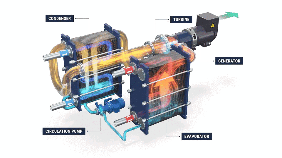
- Evaporator/Heat Exchanger – Transfers heat from the source to the organic working fluid.
- ORC Turbine/Expander – Expands the vapor to produce mechanical work, which drives a generator.
- Condenser – Cools and condenses the vapor back into liquid.
- Pump – Pressurizes the condensed fluid and recirculates it to the evaporator.
⚙️ ORC Turbine Types
- Radial (Centrifugal) Turbines – Compact, used for small to medium-scale systems.
- Axial Turbines – Used in larger systems for higher efficiency.
- Scroll or Screw Expanders – Common in micro-ORC or small-scale systems due to simplicity and cost.
💡 Advantages of ORC Turbines
- Efficient energy recovery from low-temperature heat.
- Can operate with air or water cooling.
- Lower maintenance due to lower operating temperatures and pressures.
- Environmentally friendly when using non-toxic, non-flammable fluids.
🔥 Common Heat Sources for ORC
- Industrial waste heat (from engines, furnaces, etc.)
- Geothermal reservoirs
- Biomass combustion
- Concentrated solar power (CSP)
- Marine engine exhausts
⚠️ Challenges & Considerations
- Working fluid selection is critical: it affects thermodynamic performance, safety, and environmental impact.
- Turbine design must match fluid properties and operating conditions.
- Economic feasibility: Upfront cost vs. long-term savings.
- Heat source stability and temperature consistency.
Performance Characteristics of ORC Turbines
- Efficiency: ORC systems typically operate with thermal efficiencies in the range of 8% to 20%, depending on the temperature of the heat source and the working fluid. While this is lower than steam Rankine cycles, ORCs excel in utilizing low-grade heat that would otherwise go to waste.
- Operating Conditions: ORCs usually work with heat source temperatures between 80°C and 350°C. This makes them suitable where steam turbines would be inefficient or impractical due to low heat source quality.
- Part-load Performance: Many ORC systems are designed to operate efficiently even at partial loads. This flexibility is important when dealing with variable heat sources like solar or biomass.
Design Considerations for ORC Turbines
- Working Fluid Selection: Choosing the right organic fluid is essential. Key factors include:
- Boiling point
- Critical temperature and pressure
- Thermal stability
- Environmental impact (ODP, GWP)
- Compatibility with materials and lubricants
- Turbine/Expander Design: The expander must be designed to accommodate the lower speed of sound and higher molecular mass of organic fluids compared to steam. This influences blade shape, stage number, and overall geometry.
- Heat Exchanger Design: Due to lower temperature differences, ORC heat exchangers require high surface areas and precise thermal matching to avoid losses.
- System Integration: ORC systems must be well integrated with the heat source and sink to maintain stable operation and avoid thermal cycling that could affect performance and component lifespan.
Applications of ORC Turbines
- Geothermal Power Plants: Especially in low- to medium-temperature fields (100–200°C), where steam cycles are not viable.
- Waste Heat Recovery: Used in industrial processes (steel, glass, cement) and engines (diesel generators, gas turbines).
- Biomass Power Generation: ORC is a good fit due to the relatively low combustion temperatures.
- Solar Thermal Plants: Paired with parabolic troughs or Fresnel collectors for off-grid or supplemental power.
- Combined Heat and Power (CHP): Micro-ORC units are increasingly used in decentralized energy systems to provide both electricity and useful heat.
ORC turbines operate on the Organic Rankine Cycle, which is a thermodynamic process similar to the traditional Rankine cycle but uses an organic working fluid with a low boiling point. This makes it suitable for converting low- to medium-grade heat into electricity. Instead of water or steam, ORC systems use fluids such as refrigerants or hydrocarbons, which can vaporize at much lower temperatures, enabling the system to recover energy from sources like geothermal heat, industrial waste heat, biomass combustion, or solar thermal collectors. The cycle involves heating the organic fluid in an evaporator, expanding it through a turbine to generate mechanical work (usually converted to electricity via a generator), condensing the vapor back into a liquid, and using a pump to recirculate the fluid through the cycle.
Performance in ORC turbines depends heavily on the working fluid and the temperature range of the heat source. Efficiencies typically range from 8% to 20%, which may seem low compared to conventional steam turbines but is quite effective given that ORC systems utilize heat that would otherwise be wasted. The choice of working fluid is crucial; it affects not only thermodynamic efficiency but also environmental safety, system complexity, and component compatibility. Common choices like R245fa, R1233zd, or isobutane are selected based on parameters such as boiling point, stability, and pressure requirements.
Turbine design in ORC systems has to accommodate the distinct physical properties of organic fluids. These fluids generally have higher molecular weights and lower speeds of sound, which results in different expansion behavior compared to steam. Turbines may be radial or axial, with radial being more common in smaller systems due to compactness and ease of manufacturing. In very small-scale systems, positive displacement expanders like scroll or screw types are also used. ORC turbines must handle significant volume ratios across the turbine stages and ensure minimal pressure losses to maintain efficiency.
One of the strengths of ORC technology is its modularity and adaptability. Systems can be designed in compact, containerized formats and often operate with minimal supervision due to fewer moving parts and lower operating temperatures and pressures. This leads to lower maintenance costs and longer operational life. Air cooling can replace water cooling in many installations, making ORC suitable for remote or arid locations. However, ORC systems require careful thermal integration, especially in the design of the evaporator and condenser, to ensure stable and continuous operation. Part-load efficiency is another design focus, as many real-world heat sources are variable. Proper control strategies and thermal buffering can help maintain performance under fluctuating conditions.
Applications are diverse. In geothermal power, ORC systems are ideal for regions where reservoir temperatures are too low for steam turbines. In industry, waste heat from kilns, engines, or exhaust gas can be recovered to produce electricity, reducing overall fuel consumption and emissions. In biomass plants, ORC units allow for smaller, decentralized generation units that can be installed close to fuel sources. The growing interest in distributed energy and decarbonization has made ORC systems a popular option for small- to medium-scale combined heat and power setups, where both electricity and usable heat are produced from a single fuel source.
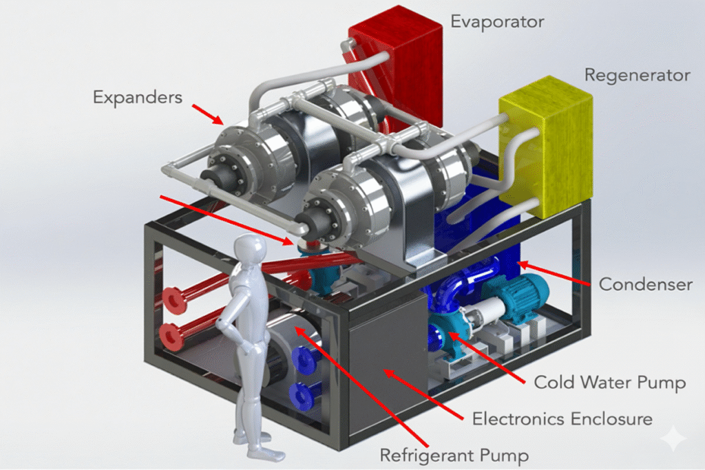
Building on that, ORC systems can be optimized in various ways to improve performance and adapt to specific applications. One common enhancement is the addition of a recuperator or regenerator, which is a heat exchanger that recovers heat from the turbine exhaust before the vapor enters the condenser. This recovered heat is then used to preheat the working fluid before it enters the evaporator. By reducing the amount of heat needed from the external source, the system improves overall thermal efficiency without increasing fuel consumption or source heat demand. Recuperated ORC systems are especially beneficial when the temperature difference between the heat source and the condenser is modest, allowing more internal heat recovery.
Another advanced configuration is the use of a supercritical ORC cycle. In this setup, the working fluid is pressurized beyond its critical point, so it doesn’t undergo a distinct phase change between liquid and vapor. This allows for smoother and more efficient heat absorption and expansion, particularly useful for higher-temperature applications. However, supercritical systems require more robust components due to higher pressures, and the selection of a working fluid becomes more complex, as the fluid must have a suitable critical point and thermal stability at elevated temperatures.
ORC systems can also be configured for multiple stages or cascaded cycles. In a cascaded cycle, two or more ORC loops operate in series or parallel, each optimized for different temperature ranges. The high-temperature loop captures energy from the primary heat source, while the lower-temperature loop extracts additional energy from the first loop’s exhaust. This approach increases overall system efficiency and allows the recovery of more energy from a broader temperature spectrum.
Control and automation are important elements in modern ORC systems. Because heat source temperatures can vary—especially in applications like waste heat recovery or biomass combustion—the ORC unit must adjust its operating conditions dynamically. This includes controlling the pump speed, turbine inlet conditions, and possibly the heat exchanger flows to maintain optimal working conditions. Advanced control systems can predict load variations and optimize start-up, shut-down, and transient response, helping to protect the turbine and other components from stress or inefficiencies.
From a practical standpoint, ORC systems are increasingly used in remote or off-grid environments. Their ability to operate with low maintenance and limited water supply makes them ideal for isolated communities, small industrial plants, or even in mobile applications like shipping, where waste heat from engines can be repurposed. In such environments, the simplicity and reliability of ORC technology offer clear advantages over more maintenance-intensive solutions like traditional steam systems or internal combustion engines.
As the technology matures, more attention is being given to the environmental impact of the working fluids themselves. Some older fluids, such as R245fa, are being phased out or restricted due to high global warming potential (GWP). New fluids like R1233zd or hydrocarbons such as isopentane and cyclopentane are being promoted for their lower environmental impact, though they may introduce flammability concerns or require specialized handling.
Cost competitiveness remains a key factor in ORC deployment. While capital costs can be higher than traditional power systems on a per-kW basis, especially in smaller-scale applications, the long-term savings from reduced fuel use and minimal maintenance can make the investment worthwhile. In many cases, financial incentives for renewable or waste heat recovery technologies can help bridge the economic gap and support deployment in sectors like agriculture, district heating, and manufacturing.
Let’s continue by looking at how ORC systems are evaluated and designed, particularly in the context of real-world deployment. One of the first steps in developing an ORC project is conducting a feasibility study, which involves assessing the quality and stability of the available heat source, the desired power output, economic viability, and integration challenges. This process starts by characterizing the heat source — whether it’s waste heat, geothermal brine, flue gas, or biomass combustion — in terms of temperature range, flow rate, chemical composition, and variability over time.
The heat source temperature is the most critical factor, as it determines not only the efficiency of the cycle but also which working fluids and turbine types can be used. Higher temperatures allow for more efficient cycles but demand fluids with greater thermal stability and systems that can withstand higher pressures. In contrast, lower temperature systems may favor simpler designs and more benign fluids, but must accept lower conversion efficiencies. The temperature glide of the heat source — the rate at which its temperature changes during heat transfer — also affects the design of the evaporator and may favor certain types of working fluids that match the glide more closely.
Once the heat source is defined, the next step involves selecting a working fluid and performing thermodynamic cycle simulations. Software tools like Engineering Equation Solver (EES), Aspen Plus, or MATLAB are often used to simulate different working fluid and system configurations. These simulations help determine the net power output, cycle efficiency, heat exchanger sizing, and component specifications. Key parameters optimized during design include turbine inlet pressure and temperature, mass flow rate of the working fluid, and the amount of recuperation or regeneration in the cycle.
After simulation, the mechanical and electrical design of the system takes place. This includes selecting or designing a suitable expander (turbine, screw, scroll, or piston), matching a generator, and sizing the heat exchangers. Heat exchanger design is a particular challenge in ORC systems due to the lower thermal gradients and the need for high effectiveness with minimal pressure drop. Shell-and-tube, plate, and brazed heat exchangers are commonly used depending on size and application.
System integration is another major design phase. ORC units often operate alongside other energy systems, such as internal combustion engines (in waste heat recovery), heating systems (in CHP setups), or cooling systems (in tri-generation plants). In these cases, thermal balance and control logic must be carefully planned to avoid waste or inefficiency. For example, if the heat source fluctuates or is intermittent, a thermal buffer (like a hot water tank or molten salt storage) may be introduced to decouple the ORC system’s operation from the heat source.
In commercial and industrial applications, the economic analysis must also be rigorous. Capital expenditures (CAPEX), operating expenditures (OPEX), payback period, and levelized cost of electricity (LCOE) are all key financial metrics. These are affected by factors like equipment cost, installation, operation, fluid replacement intervals, and downtime. Government incentives or feed-in tariffs for renewable energy or energy efficiency improvements can significantly enhance the economic case for ORC deployment.
Monitoring and control play a significant role in long-term performance. Sensors for temperature, pressure, flow, and vibration are typically installed throughout the system, feeding data into a programmable logic controller (PLC) or a supervisory control and data acquisition (SCADA) system. These systems help optimize power output, detect faults early, and log performance data for maintenance or improvement planning.
In real-world deployments, ORC systems have proven particularly successful in industries such as cement, glass, steel, and chemical processing, where high-temperature waste heat is abundant. Geothermal installations are also increasing in number, especially in countries like Turkey, Indonesia, and Kenya, where moderate-temperature resources are widespread. In rural or developing regions, ORC systems can offer a decentralized way to generate power from biomass or geothermal heat, supporting electrification and energy resilience.
Overall, ORC technology continues to evolve, with improvements in materials, cycle design, and controls contributing to higher efficiencies, lower costs, and broader adoption. Innovations like scroll expanders for ultra-low power systems, hybrid cycles that integrate ORC with solar PV or battery storage, and containerized ORC units for plug-and-play deployment are all pushing the technology into new markets and use cases.
ORC turbines refer to Organic Rankine Cycle (ORC) turbines, which are used in systems designed to convert low- to medium-temperature heat sources into electrical power. Instead of using water/steam like in traditional Rankine cycles, ORC systems use organic fluids (like hydrocarbons or refrigerants) with lower boiling points, making them ideal for waste heat recovery, geothermal, solar thermal, and biomass applications.
🔧 Key Components of an ORC System
- Evaporator/Heat Exchanger – Transfers heat from the source to the organic working fluid.
- ORC Turbine/Expander – Expands the vapor to produce mechanical work, which drives a generator.
- Condenser – Cools and condenses the vapor back into liquid.
- Pump – Pressurizes the condensed fluid and recirculates it to the evaporator.
⚙️ ORC Turbine Types
- Radial (Centrifugal) Turbines – Compact, used for small to medium-scale systems.
- Axial Turbines – Used in larger systems for higher efficiency.
- Scroll or Screw Expanders – Common in micro-ORC or small-scale systems due to simplicity and cost.
💡 Advantages of ORC Turbines
- Efficient energy recovery from low-temperature heat.
- Can operate with air or water cooling.
- Lower maintenance due to lower operating temperatures and pressures.
- Environmentally friendly when using non-toxic, non-flammable fluids.
🔥 Common Heat Sources for ORC
- Industrial waste heat (from engines, furnaces, etc.)
- Geothermal reservoirs
- Biomass combustion
- Concentrated solar power (CSP)
- Marine engine exhausts
⚠️ Challenges & Considerations
- Working fluid selection is critical: it affects thermodynamic performance, safety, and environmental impact.
- Turbine design must match fluid properties and operating conditions.
- Economic feasibility: Upfront cost vs. long-term savings.
- Heat source stability and temperature consistency.
Performance Characteristics of ORC Turbines
- Efficiency: ORC systems typically operate with thermal efficiencies in the range of 8% to 20%, depending on the temperature of the heat source and the working fluid. While this is lower than steam Rankine cycles, ORCs excel in utilizing low-grade heat that would otherwise go to waste.
- Operating Conditions: ORCs usually work with heat source temperatures between 80°C and 350°C. This makes them suitable where steam turbines would be inefficient or impractical due to low heat source quality.
- Part-load Performance: Many ORC systems are designed to operate efficiently even at partial loads. This flexibility is important when dealing with variable heat sources like solar or biomass.
Design Considerations for ORC Turbines
- Working Fluid Selection: Choosing the right organic fluid is essential. Key factors include:
- Boiling point
- Critical temperature and pressure
- Thermal stability
- Environmental impact (ODP, GWP)
- Compatibility with materials and lubricants
- Turbine/Expander Design: The expander must be designed to accommodate the lower speed of sound and higher molecular mass of organic fluids compared to steam. This influences blade shape, stage number, and overall geometry.
- Heat Exchanger Design: Due to lower temperature differences, ORC heat exchangers require high surface areas and precise thermal matching to avoid losses.
- System Integration: ORC systems must be well integrated with the heat source and sink to maintain stable operation and avoid thermal cycling that could affect performance and component lifespan.
Applications of ORC Turbines
- Geothermal Power Plants: Especially in low- to medium-temperature fields (100–200°C), where steam cycles are not viable.
- Waste Heat Recovery: Used in industrial processes (steel, glass, cement) and engines (diesel generators, gas turbines).
- Biomass Power Generation: ORC is a good fit due to the relatively low combustion temperatures.
- Solar Thermal Plants: Paired with parabolic troughs or Fresnel collectors for off-grid or supplemental power.
- Combined Heat and Power (CHP): Micro-ORC units are increasingly used in decentralized energy systems to provide both electricity and useful heat.
ORC turbines operate on the Organic Rankine Cycle, which is a thermodynamic process similar to the traditional Rankine cycle but uses an organic working fluid with a low boiling point. This makes it suitable for converting low- to medium-grade heat into electricity. Instead of water or steam, ORC systems use fluids such as refrigerants or hydrocarbons, which can vaporize at much lower temperatures, enabling the system to recover energy from sources like geothermal heat, industrial waste heat, biomass combustion, or solar thermal collectors. The cycle involves heating the organic fluid in an evaporator, expanding it through a turbine to generate mechanical work (usually converted to electricity via a generator), condensing the vapor back into a liquid, and using a pump to recirculate the fluid through the cycle.
Performance in ORC turbines depends heavily on the working fluid and the temperature range of the heat source. Efficiencies typically range from 8% to 20%, which may seem low compared to conventional steam turbines but is quite effective given that ORC systems utilize heat that would otherwise be wasted. The choice of working fluid is crucial; it affects not only thermodynamic efficiency but also environmental safety, system complexity, and component compatibility. Common choices like R245fa, R1233zd, or isobutane are selected based on parameters such as boiling point, stability, and pressure requirements.
Turbine design in ORC systems has to accommodate the distinct physical properties of organic fluids. These fluids generally have higher molecular weights and lower speeds of sound, which results in different expansion behavior compared to steam. Turbines may be radial or axial, with radial being more common in smaller systems due to compactness and ease of manufacturing. In very small-scale systems, positive displacement expanders like scroll or screw types are also used. ORC turbines must handle significant volume ratios across the turbine stages and ensure minimal pressure losses to maintain efficiency.
One of the strengths of ORC technology is its modularity and adaptability. Systems can be designed in compact, containerized formats and often operate with minimal supervision due to fewer moving parts and lower operating temperatures and pressures. This leads to lower maintenance costs and longer operational life. Air cooling can replace water cooling in many installations, making ORC suitable for remote or arid locations. However, ORC systems require careful thermal integration, especially in the design of the evaporator and condenser, to ensure stable and continuous operation. Part-load efficiency is another design focus, as many real-world heat sources are variable. Proper control strategies and thermal buffering can help maintain performance under fluctuating conditions.
Applications are diverse. In geothermal power, ORC systems are ideal for regions where reservoir temperatures are too low for steam turbines. In industry, waste heat from kilns, engines, or exhaust gas can be recovered to produce electricity, reducing overall fuel consumption and emissions. In biomass plants, ORC units allow for smaller, decentralized generation units that can be installed close to fuel sources. The growing interest in distributed energy and decarbonization has made ORC systems a popular option for small- to medium-scale combined heat and power setups, where both electricity and usable heat are produced from a single fuel source.
Building on that, ORC systems can be optimized in various ways to improve performance and adapt to specific applications. One common enhancement is the addition of a recuperator or regenerator, which is a heat exchanger that recovers heat from the turbine exhaust before the vapor enters the condenser. This recovered heat is then used to preheat the working fluid before it enters the evaporator. By reducing the amount of heat needed from the external source, the system improves overall thermal efficiency without increasing fuel consumption or source heat demand. Recuperated ORC systems are especially beneficial when the temperature difference between the heat source and the condenser is modest, allowing more internal heat recovery.
Another advanced configuration is the use of a supercritical ORC cycle. In this setup, the working fluid is pressurized beyond its critical point, so it doesn’t undergo a distinct phase change between liquid and vapor. This allows for smoother and more efficient heat absorption and expansion, particularly useful for higher-temperature applications. However, supercritical systems require more robust components due to higher pressures, and the selection of a working fluid becomes more complex, as the fluid must have a suitable critical point and thermal stability at elevated temperatures.
ORC systems can also be configured for multiple stages or cascaded cycles. In a cascaded cycle, two or more ORC loops operate in series or parallel, each optimized for different temperature ranges. The high-temperature loop captures energy from the primary heat source, while the lower-temperature loop extracts additional energy from the first loop’s exhaust. This approach increases overall system efficiency and allows the recovery of more energy from a broader temperature spectrum.
Control and automation are important elements in modern ORC systems. Because heat source temperatures can vary—especially in applications like waste heat recovery or biomass combustion—the ORC unit must adjust its operating conditions dynamically. This includes controlling the pump speed, turbine inlet conditions, and possibly the heat exchanger flows to maintain optimal working conditions. Advanced control systems can predict load variations and optimize start-up, shut-down, and transient response, helping to protect the turbine and other components from stress or inefficiencies.
From a practical standpoint, ORC systems are increasingly used in remote or off-grid environments. Their ability to operate with low maintenance and limited water supply makes them ideal for isolated communities, small industrial plants, or even in mobile applications like shipping, where waste heat from engines can be repurposed. In such environments, the simplicity and reliability of ORC technology offer clear advantages over more maintenance-intensive solutions like traditional steam systems or internal combustion engines.
As the technology matures, more attention is being given to the environmental impact of the working fluids themselves. Some older fluids, such as R245fa, are being phased out or restricted due to high global warming potential (GWP). New fluids like R1233zd or hydrocarbons such as isopentane and cyclopentane are being promoted for their lower environmental impact, though they may introduce flammability concerns or require specialized handling.
Cost competitiveness remains a key factor in ORC deployment. While capital costs can be higher than traditional power systems on a per-kW basis, especially in smaller-scale applications, the long-term savings from reduced fuel use and minimal maintenance can make the investment worthwhile. In many cases, financial incentives for renewable or waste heat recovery technologies can help bridge the economic gap and support deployment in sectors like agriculture, district heating, and manufacturing.
Let’s continue by looking at how ORC systems are evaluated and designed, particularly in the context of real-world deployment. One of the first steps in developing an ORC project is conducting a feasibility study, which involves assessing the quality and stability of the available heat source, the desired power output, economic viability, and integration challenges. This process starts by characterizing the heat source — whether it’s waste heat, geothermal brine, flue gas, or biomass combustion — in terms of temperature range, flow rate, chemical composition, and variability over time.
The heat source temperature is the most critical factor, as it determines not only the efficiency of the cycle but also which working fluids and turbine types can be used. Higher temperatures allow for more efficient cycles but demand fluids with greater thermal stability and systems that can withstand higher pressures. In contrast, lower temperature systems may favor simpler designs and more benign fluids, but must accept lower conversion efficiencies. The temperature glide of the heat source — the rate at which its temperature changes during heat transfer — also affects the design of the evaporator and may favor certain types of working fluids that match the glide more closely.
Once the heat source is defined, the next step involves selecting a working fluid and performing thermodynamic cycle simulations. Software tools like Engineering Equation Solver (EES), Aspen Plus, or MATLAB are often used to simulate different working fluid and system configurations. These simulations help determine the net power output, cycle efficiency, heat exchanger sizing, and component specifications. Key parameters optimized during design include turbine inlet pressure and temperature, mass flow rate of the working fluid, and the amount of recuperation or regeneration in the cycle.
After simulation, the mechanical and electrical design of the system takes place. This includes selecting or designing a suitable expander (turbine, screw, scroll, or piston), matching a generator, and sizing the heat exchangers. Heat exchanger design is a particular challenge in ORC systems due to the lower thermal gradients and the need for high effectiveness with minimal pressure drop. Shell-and-tube, plate, and brazed heat exchangers are commonly used depending on size and application.
System integration is another major design phase. ORC units often operate alongside other energy systems, such as internal combustion engines (in waste heat recovery), heating systems (in CHP setups), or cooling systems (in tri-generation plants). In these cases, thermal balance and control logic must be carefully planned to avoid waste or inefficiency. For example, if the heat source fluctuates or is intermittent, a thermal buffer (like a hot water tank or molten salt storage) may be introduced to decouple the ORC system’s operation from the heat source.
In commercial and industrial applications, the economic analysis must also be rigorous. Capital expenditures (CAPEX), operating expenditures (OPEX), payback period, and levelized cost of electricity (LCOE) are all key financial metrics. These are affected by factors like equipment cost, installation, operation, fluid replacement intervals, and downtime. Government incentives or feed-in tariffs for renewable energy or energy efficiency improvements can significantly enhance the economic case for ORC deployment.
Monitoring and control play a significant role in long-term performance. Sensors for temperature, pressure, flow, and vibration are typically installed throughout the system, feeding data into a programmable logic controller (PLC) or a supervisory control and data acquisition (SCADA) system. These systems help optimize power output, detect faults early, and log performance data for maintenance or improvement planning.
In real-world deployments, ORC systems have proven particularly successful in industries such as cement, glass, steel, and chemical processing, where high-temperature waste heat is abundant. Geothermal installations are also increasing in number, especially in countries like Turkey, Indonesia, and Kenya, where moderate-temperature resources are widespread. In rural or developing regions, ORC systems can offer a decentralized way to generate power from biomass or geothermal heat, supporting electrification and energy resilience.
Overall, ORC technology continues to evolve, with improvements in materials, cycle design, and controls contributing to higher efficiencies, lower costs, and broader adoption. Innovations like scroll expanders for ultra-low power systems, hybrid cycles that integrate ORC with solar PV or battery storage, and containerized ORC units for plug-and-play deployment are all pushing the technology into new markets and use cases.
1. Evaporator (or Vaporizer)
The evaporator is the heat exchanger where the working fluid absorbs thermal energy from the heat source and evaporates. Its performance is critical since it directly affects the amount of energy input to the cycle. Depending on the temperature profile and phase change characteristics of the working fluid, the evaporator may be:
- Single-phase (sensible heating only)
- Two-phase (with boiling occurring inside the heat exchanger)
Design considerations:
- Large surface area to handle low temperature differences.
- Material compatibility with the heat source (especially corrosive exhaust gases or geothermal fluids).
- Pressure drop management to prevent efficiency loss.
- Sometimes includes pre-heaters and separate superheaters to better control the fluid state at turbine entry.
2. Expander (ORC Turbine)
This is the heart of the ORC system — it converts the thermal energy of the vapor into mechanical work. The expander is typically connected to a generator to produce electricity. Depending on the power level and fluid, the expander can be:
- Radial/centrifugal turbines for small to medium power.
- Axial turbines for larger-scale systems.
- Screw, scroll, or piston expanders for micro-ORC (e.g., <50 kW).
Design considerations:
- Must accommodate high volume flow due to low density of organic vapors.
- Low inlet velocities compared to steam expanders.
- Efficiency depends on blade design, tip clearance, number of stages.
- Seal systems must handle potentially flammable or toxic fluids.
3. Generator
The mechanical energy from the expander is used to rotate a generator that produces electricity. This may be:
- A direct-coupled synchronous generator (common in large systems).
- An asynchronous generator or even a permanent magnet generator for smaller, variable-speed systems.
Considerations:
- Electrical efficiency and compatibility with local grid requirements.
- Use of inverters or converters for frequency/voltage regulation.
4. Condenser
The condenser is where the vapor leaving the turbine is cooled and condensed back into liquid form. This is crucial for closing the cycle and preparing the fluid for re-pressurization. It may be:
- Air-cooled: suitable for dry or remote locations, but less efficient.
- Water-cooled: higher efficiency but requires water supply and treatment.
Design considerations:
- Must handle large volumetric flow and latent heat rejection.
- High effectiveness is key to maximize recovery.
- Material selection for outdoor or corrosive environments.
5. Pump
After condensation, the working fluid is at low pressure. The pump increases its pressure before sending it back to the evaporator. It must handle:
- Liquids with varying viscosities and lubricating properties.
- Sometimes low NPSH (Net Positive Suction Head) conditions due to condenser placement.
Types:
- Gear pumps or diaphragm pumps for low flow rates.
- Centrifugal or multistage pumps for higher pressures and flows.
Efficiency matters here — the pump consumes power and cuts into net output, so minimizing pump work is essential for cycle efficiency.
6. Recuperator (Optional)
A recuperator recovers heat from the turbine exhaust before the vapor reaches the condenser, using it to preheat the working fluid before it enters the evaporator. This reduces the external heat requirement and improves thermal efficiency. It’s only used when the working fluid and temperature conditions allow effective internal heat exchange.
Challenges:
- Matching temperature profiles (pinch points).
- Managing pressure losses and fluid compatibility.
7. Control System
The PLC or control system manages fluid flow, turbine speed, pressure regulation, safety interlocks, and data logging. It also ensures efficient and safe operation under variable load and heat input conditions.
Features:
- Auto start/stop.
- Alarms and shutdown protocols for overpressure, overtemperature, fluid loss, etc.
- Communication with SCADA or energy management systems.
8. Auxiliary Systems
These include:
- Working fluid reservoir: to compensate for fluid loss or thermal expansion.
- Lubrication system: for turbine bearings or mechanical seals, especially if the fluid lacks lubricity.
- Filters and driers: to maintain fluid purity and avoid fouling or corrosion.
- Bypass valves: to allow safe operation during transients or maintenance.
Evaporator (or Vaporizer)
The evaporator, also called the vaporizer, is the component in an ORC system where thermal energy from the external heat source is transferred to the working fluid, causing it to evaporate and become high-pressure vapor. It’s one of the most critical parts of the cycle because it directly determines how much energy is available for conversion to mechanical work in the turbine. The performance of the evaporator impacts the overall thermal efficiency, power output, and stability of the system. Depending on the design and the heat source characteristics, the evaporator may consist of several stages or zones: a preheater section where the fluid is warmed up to near boiling, a phase-change section where it evaporates, and sometimes a superheater section where it’s heated further above its saturation temperature before entering the turbine.
The heat source can be anything from geothermal brine, engine exhaust gases, flue gas from a biomass furnace, to hot water from an industrial process. Each type of heat source brings unique challenges. For example, geothermal fluids can contain corrosive minerals, while exhaust gases may have particulates or require thermal buffering to avoid surges in temperature. Therefore, material selection for the evaporator is very important — it must resist corrosion, withstand thermal stresses, and be compatible with both the working fluid and the heat source medium.
The evaporator must provide a large heat transfer surface area because ORC fluids typically have a much lower heat of vaporization compared to water, and the temperature differences (delta-T) between the heat source and the working fluid are often small. This means heat transfer is less aggressive, so efficient surface area usage is essential. Finned tubes, plate heat exchangers, or shell-and-tube designs are commonly used depending on the application size and type of fluid. A key design consideration is maintaining a proper temperature profile that matches the heat source to the fluid’s boiling curve. This is often referred to as thermal matching or pinch point optimization. If not done well, it can lead to exergy losses and suboptimal performance.
Another challenge is managing pressure drops across the evaporator. High pressure drop not only reduces turbine inlet pressure and cycle efficiency but also increases the required pumping power. Therefore, engineers aim to balance heat transfer effectiveness with minimal flow resistance. Internally, the evaporator may operate in a horizontal or vertical configuration, and whether the working fluid boils inside the tubes or outside can depend on which side the heat source flows and the fouling characteristics of both fluids.
Finally, control and monitoring of the evaporator are crucial for safe and stable ORC operation. Temperature sensors, pressure transducers, and flow meters are usually installed to monitor performance and detect anomalies like dry-out, scaling, or flow blockage. In some systems, bypass valves or buffer tanks may be used to smooth temperature fluctuations in the heat source. The evaporator is not only where energy enters the cycle — it’s also where many failure modes can originate if design and control are inadequate. Therefore, its design must be thoroughly integrated with the rest of the ORC system for reliable long-term operation.
Because the evaporator handles the point of phase change in the ORC system, it must also be designed to manage the dynamics of boiling — a process that is highly sensitive to pressure, flow rate, and heat flux. The boiling behavior of organic fluids differs significantly from that of water. Many organic fluids exhibit lower surface tension and different nucleate boiling characteristics, which can lead to earlier onset of dry-out or film boiling if not carefully managed. In systems where the working fluid is superheated before entering the turbine, the evaporator needs to ensure that this superheating occurs evenly and predictably, as fluctuations can lead to turbine inefficiencies or even mechanical stress.
In practice, the evaporator may be divided into sections with separate controls or passes, especially in large or complex systems. For instance, a counter-flow arrangement is often used where the heat source and working fluid flow in opposite directions to maintain a more uniform temperature difference along the heat exchanger length. This approach improves the thermal effectiveness of the unit and helps avoid temperature pinch points — areas where the temperature difference is too small to effectively transfer heat, which can cause underperformance and increased entropy generation.
Fouling is another practical concern in evaporators. Depending on the heat source, solid particles, mineral scaling, or chemical deposition can build up on the heat transfer surfaces, reducing effectiveness over time. In geothermal applications, silica scaling is particularly common, while in biomass or waste-heat applications, tar, ash, or soot may accumulate. This means that ease of maintenance and cleanability is an important design factor. Plate heat exchangers, for example, offer compactness and good thermal efficiency, but may be more difficult to clean if the heat source is dirty or corrosive. Shell-and-tube heat exchangers, while larger, are often preferred for heavy-duty industrial applications due to their robustness and accessibility.
Operational control of the evaporator must account for the heat source variability and working fluid characteristics. If the heat source fluctuates — as it often does in waste heat recovery or solar thermal systems — the control system must adjust fluid flow rates to maintain proper boiling conditions. Too little heat input may result in incomplete vaporization, sending a mixture of liquid and vapor into the turbine, which is harmful to both performance and mechanical integrity. Too much heat without flow control can lead to overheating or thermal degradation of the working fluid, especially for fluids with low thermal stability.
The evaporator also plays a role in safety. It typically operates at the highest pressure and temperature conditions in the entire ORC system. Pressure relief valves, rupture discs, and temperature cutoffs are common safety features installed around this component. In some designs, thermal expansion and fluid density changes must be considered to avoid overpressure during start-up or shut-down sequences.
All of these considerations highlight that the evaporator is not just a heat exchanger but a highly dynamic interface between the ORC system and the energy source. It must be carefully tailored for the heat source type, the working fluid behavior, the required system response time, and the maintenance strategy of the facility. Proper design and integration of the evaporator can significantly improve overall ORC performance, efficiency, and reliability.
Expander (ORC Turbine)
The expander, often referred to as the ORC turbine, is the component responsible for converting the thermal energy of the high-pressure vaporized working fluid into mechanical energy. This mechanical energy is typically used to drive an electric generator, but in some applications it may also power a compressor or other mechanical equipment directly. The expander is a crucial part of the ORC system, as its efficiency has a significant impact on the overall performance and energy yield of the cycle. The design and selection of the expander must consider the properties of the working fluid, the required output power, the operating pressure and temperature range, and the desired speed and response of the system.
Unlike steam turbines, ORC expanders must handle fluids with much lower density and often higher molecular weight. This means that, for a given power output, the volumetric flow rate through an ORC turbine is significantly higher than in a steam turbine, even though the mass flow may be similar or lower. As a result, the expander must be designed with larger flow passages and possibly multiple stages to accommodate the high volumetric flow. The blade geometry, nozzle design, and rotor layout are all tailored to the specific behavior of organic fluids, which often have flatter saturation curves and different condensation behavior compared to water.
There are several types of expanders used in ORC systems, and the choice depends on the application size, working fluid, and cost constraints. In medium to large-scale systems, radial inflow turbines or axial turbines are common. These are similar in principle to those used in steam or gas turbines, but optimized for organic fluids and typically designed for lower inlet temperatures and pressures. In small-scale or micro-ORC systems, positive displacement expanders such as screw, scroll, or piston expanders are frequently used. These devices can operate efficiently at low speeds, are robust against liquid carryover, and can handle varying loads and off-design conditions better than high-speed turbines.
The mechanical design of the expander must also take into account the lubricating properties of the working fluid. Some organic fluids are poor lubricants, which can affect bearing design and seal longevity. In such cases, separate oil systems may be used to lubricate bearings, or magnetic bearings might be employed in advanced systems to eliminate the need for lubrication altogether. Sealing is another critical challenge, especially with fluids that are flammable, toxic, or sensitive to moisture. Mechanical seals, labyrinth seals, or dry gas seals are used depending on the fluid properties and pressure levels. Hermetically sealed expanders, where the expander and generator are enclosed in a common housing and the working fluid itself is used for cooling, are popular in smaller systems because they reduce leak risks and maintenance.
Efficiency in ORC turbines is generally lower than in large steam turbines, mainly due to the smaller pressure ratios, lower turbine inlet temperatures, and the physical characteristics of the fluids. However, modern ORC turbines can achieve isentropic efficiencies of 70–85% in well-designed systems. The turbine must be designed not only for high efficiency at nominal conditions but also for robustness and flexibility, as many ORC systems operate under variable load or with fluctuating heat source conditions. Variable geometry nozzles, sliding vanes, or bypass valves can help adjust the turbine’s performance dynamically.
The integration of the expander with the generator is also a key design area. For grid-connected systems, the generator must produce power at stable frequency and voltage, requiring synchronization and potentially power electronics such as inverters. For standalone or off-grid systems, variable-speed generators may be used with direct current output and battery storage or hybrid operation. In all cases, vibration monitoring, speed sensors, temperature probes, and pressure transducers are typically installed on or near the expander to ensure safe and efficient operation.
Overall, the expander is not only the energy conversion core of the ORC cycle but also a complex mechanical system that must be carefully engineered to match the thermal and physical characteristics of the working fluid and the application requirements. Its performance is central to the economic and technical success of an ORC installation, making it one of the most intensively developed and optimized components in the field.
In addition to its core mechanical design, the expander must also be engineered for long-term durability under cyclic thermal and mechanical loading. ORC systems often operate in environments where startup and shutdown may occur frequently, such as in waste heat recovery systems tied to industrial processes that do not run continuously. This means the expander must withstand not only the steady-state thermodynamic stresses of high-speed rotation and pressure differentials, but also the transient stresses from thermal expansion, temperature swings, and vibration. Material selection plays a crucial role here. Components such as rotors, casings, and blades are typically made from stainless steels, high-temperature alloys, or in some cases, advanced composites, depending on the temperature, pressure, and fluid compatibility.
For high-efficiency operation, it’s essential to maintain close tolerances between moving and stationary parts within the expander. However, the organic fluids used in ORC systems can sometimes break down or polymerize at high temperatures, potentially leading to deposits or fouling inside the turbine. This is particularly problematic in systems that do not control superheating well or allow the working fluid to overheat. Therefore, thermal stability of the working fluid is closely tied to expander reliability. Some systems include filtration and fluid conditioning loops to remove contaminants and preserve the integrity of the expander over time.
Acoustic noise and mechanical vibration are also non-trivial concerns, especially in environments where the ORC system is located near sensitive equipment or within buildings. High-speed radial turbines may produce high-frequency noise, while scroll and screw expanders, though quieter, may still require vibration isolation mounts. Active monitoring systems can detect early signs of imbalance, misalignment, or bearing wear, helping to prevent catastrophic failures and enabling predictive maintenance.
Advanced ORC systems now often integrate control strategies that adapt expander performance to changing conditions. These may include model-based controllers that optimize expander speed, nozzle opening, or working fluid flow based on real-time sensor data. In systems where the heat source is variable — like solar thermal or exhaust gas recovery — the expander may operate across a wide range of loads. Maintaining high efficiency across this range is a challenge, which is why variable geometry turbines and multi-stage expanders are areas of ongoing research. For low-load conditions, systems may temporarily bypass the turbine or operate it at reduced speed to avoid inefficient partial-load performance.
In modular or containerized ORC systems, the expander is often designed as part of an integrated turbogen unit. This compact assembly includes the turbine, generator, lubrication system, and sometimes even the control electronics, all mounted on a single skid. Such modularity makes transport, installation, and maintenance easier, particularly in remote or mobile applications. These integrated units are factory-tested and shipped ready to install, reducing on-site commissioning time and improving overall system reliability.
In very small-scale ORC systems — such as those used in remote telemetry, micro-CHP, or solar-powered units — expanders based on scroll, piston, or even Tesla turbine principles have been explored. Scroll expanders are valued for their simplicity and ability to operate efficiently at small scales and low pressure ratios. Piston expanders offer high starting torque and robustness, making them useful for field conditions. Although these small-scale expanders typically have lower isentropic efficiency than large turbines, they open the door to new markets and use cases where simplicity, cost, and durability are more important than peak thermodynamic performance.
Overall, the expander is not only the mechanical engine of the ORC system but also a critical interface between thermodynamics and real-world mechanical engineering. Its design requires a careful balance between aerodynamic efficiency, structural strength, fluid dynamics, and control integration. Innovations in this area continue to improve ORC viability across scales and sectors, from megawatt-scale geothermal installations to kilowatt-scale microgenerators powered by waste heat or solar collectors.
Generator
The generator in an ORC system is responsible for converting the mechanical energy produced by the expander into electrical energy. It plays a central role in ensuring the system delivers usable power for either direct use or grid integration. In larger systems, the generator is typically a synchronous type, while in smaller systems, asynchronous or permanent magnet generators (PMGs) are often used. The generator is connected directly to the expander via a shaft, which transfers the rotational mechanical energy produced by the turbine. The size and type of generator are selected based on the expander’s mechanical output (torque and speed) and the system’s power requirements.
For larger ORC systems, the generator may operate at a constant speed synchronized with the grid frequency, while in smaller, off-grid systems, the generator may operate at variable speeds to match the fluctuating power input from the expander. Variable-speed generators are particularly useful when dealing with heat sources that produce intermittent or variable energy, such as waste heat recovery or solar thermal applications. These generators often require additional power electronics, such as inverters or frequency converters, to ensure that the electrical output is in the correct form for use or to be fed into the grid.
The mechanical coupling between the expander and the generator is a key design consideration. In many cases, a direct mechanical connection is used, but in systems where space or alignment is an issue, gearboxes or belt drives may be employed to optimize the rotational speed and torque from the expander. This coupling must ensure that the generator can maintain its required speed and deliver power smoothly, even when the expander’s output fluctuates due to changes in the heat source or system load.
Generators are also designed to work efficiently across a wide range of operating conditions. For instance, a well-designed generator can tolerate changes in speed and torque, ensuring that power conversion remains efficient and stable even during start-up, shut-down, or variable-load conditions. In grid-connected systems, the generator must provide stable power that meets grid voltage and frequency requirements, which may necessitate the use of additional components like voltage regulators, transformers, and synchronization equipment to ensure compatibility with the local electricity grid.
The generator’s role in power quality is crucial. In systems that supply electricity to the grid, harmonics, voltage spikes, and other power quality issues must be minimized. For off-grid applications, a clean and stable power output is needed to ensure compatibility with sensitive equipment. The generator is also often coupled with protective equipment such as circuit breakers, fuses, and safety switches to protect both the ORC system and any connected load from electrical faults.
Durability and reliability are essential for the generator, as ORC systems are often designed for continuous or long-term operation in harsh environments. Generators are typically built to withstand high vibrations, extreme temperatures, and potential exposure to the working fluid, which may be chemically aggressive or have high moisture content. Regular maintenance and monitoring of the generator’s condition, including checking for wear on bearings, rotor balancing, and electrical connections, help ensure a long operational life and avoid costly downtime.
In smaller-scale ORC systems, where cost and size are more important, PMGs and asynchronous generators are often used. These types of generators are typically simpler, more compact, and require less maintenance than synchronous generators, but they still provide efficient power conversion. Their design is also less sensitive to variations in load or input speed, which makes them well-suited for applications where the input power from the expander may be less stable.
The integration of the generator with the control system is another important aspect. The generator’s output needs to be carefully controlled and regulated, especially in cases where the load may change rapidly or where the ORC system is part of a hybrid setup, such as a combined heat and power (CHP) system or a microgrid. Power electronics and control algorithms ensure that the generator maintains consistent output while matching the power demand, or when necessary, charges energy storage systems.
In summary, the generator in an ORC system serves as the electrical interface of the entire cycle. It must be designed to efficiently convert the mechanical power from the expander into electrical energy, with consideration given to operational stability, load fluctuations, and system integration. The generator’s performance is critical to the overall efficiency and economic success of the ORC system, ensuring that the energy produced by the system is effectively captured and delivered to its intended use or grid connection.
The generator’s performance in an ORC system is influenced by several factors, including the efficiency of the expander, the design of the generator itself, and the way the system operates across different load conditions. As the expander’s rotational speed changes based on varying thermal input from the heat source, the generator must adapt to ensure that it produces a steady and stable output. This is particularly challenging in systems with variable heat sources, such as those using waste heat or renewable sources like solar or biomass, where the power input to the expander can fluctuate.
In such cases, the generator’s ability to operate efficiently across a wide range of speeds is critical. Modern ORC systems often employ variable-speed generators that can adjust to the changing speed of the turbine. These generators may include power electronics like inverters or frequency converters, which adjust the electrical output to maintain stable voltage and frequency regardless of fluctuations in the expander’s speed. This is essential for maintaining the quality of the electricity and ensuring that the generator is compatible with electrical grid requirements or end-user equipment.
Additionally, electrical protection systems are integrated into ORC systems to safeguard both the generator and the connected grid or load. Overcurrent protection, short-circuit protection, and voltage regulation systems are standard features that ensure the safety of the electrical components. For instance, if the expander’s output fluctuates significantly or if there is a mechanical failure in the expander, the generator must quickly disconnect or adjust to prevent electrical damage or overloads.
In some ORC systems, battery storage systems are also incorporated to buffer fluctuations in power generation, allowing for smoother integration with the grid or ensuring stable electricity supply for off-grid applications. In these systems, the generator may charge the batteries when there is excess power or discharge them to provide additional energy when the expander is operating below capacity.
The generator also plays a role in thermal management. While the expander produces mechanical power, it also generates waste heat, and this heat must be efficiently dissipated to prevent overheating and damage to the generator and associated components. This is typically managed through cooling systems such as air-cooled or water-cooled heat exchangers, which ensure that the generator operates within its optimal temperature range.
The generator must be highly durable since ORC systems often run continuously over long periods. Regular monitoring is crucial for assessing its health and performance. Vibration analysis, temperature monitoring, and electrical diagnostics are typically implemented to detect early signs of wear or failure in components like bearings, stators, rotors, and electrical windings. Predictive maintenance strategies, utilizing real-time data, can help optimize downtime and minimize the risk of unexpected failures.
For systems in harsh environments, such as offshore installations, remote locations, or industrial plants, special considerations are made for the generator’s environmental resilience. The generator may need to be sealed to prevent exposure to dust, moisture, or chemicals that could degrade performance. In these cases, corrosion-resistant materials and hermetically sealed enclosures are often used to ensure the system’s longevity and reliability.
Another key consideration is the maintenance and accessibility of the generator. For large-scale ORC systems, it’s important to design the generator for easy maintenance, which may include quick access to critical components for inspection, cleaning, or replacement. Maintenance schedules typically include routine checks of electrical connections, cleaning of cooling systems, and testing of safety devices. For small-scale systems, ease of serviceability becomes even more critical, as they may be deployed in remote locations or in areas with limited technical support.
The generator’s performance also impacts the overall system economics. A more efficient generator will maximize the system’s energy output, ensuring better returns on investment. For smaller-scale ORC systems, the generator represents a significant portion of the system’s cost. Therefore, choosing an appropriately sized generator that balances cost, efficiency, and operational requirements is crucial for ensuring the system’s economic feasibility.
Finally, as the technology continues to evolve, there is increasing interest in hybrid systems where ORC generators are combined with other forms of power generation or energy storage to maximize energy production. For example, ORC systems may be integrated with solar photovoltaic panels or biogas generators to create a more stable and reliable energy source. In these hybrid systems, the generator must be capable of seamlessly switching between different power sources, requiring advanced control systems and smart grid integration.
In summary, the generator in an ORC system is essential for converting mechanical energy into electrical power, ensuring that the system operates efficiently and reliably across varying loads and conditions. It must be designed to handle fluctuations in power input, maintain consistent output quality, and integrate effectively with grid or off-grid applications. Its durability, performance under varying conditions, and ability to adapt to changes in the expander’s behavior all contribute to the overall success and efficiency of the ORC system.
Condenser
The condenser in an ORC system plays a critical role in rejecting waste heat from the working fluid after it has passed through the expander. Its primary function is to convert the low-pressure vapor exiting the expander back into a liquid, enabling the cycle to continue. This is typically done by cooling the vapor and condensing it into a liquid phase, often by transferring heat to a secondary medium, such as air, water, or another cooling fluid. The design and efficiency of the condenser significantly influence the overall performance and efficiency of the ORC system, as it determines how much heat is rejected from the cycle and how effectively the working fluid can be cooled for the next cycle.
The condenser must operate under low pressure conditions, which often means it has to handle large volumes of vapor. The type of cooling used in the condenser—whether air cooling, water cooling, or another method—depends on the availability and temperature of the cooling medium, as well as the design goals of the system. In air-cooled condensers, large surface areas are needed to dissipate heat, while in water-cooled systems, heat is typically rejected to a nearby river, cooling tower, or heat exchanger system.
Efficient heat transfer is paramount in the condenser, as it affects the cycle’s ability to maintain low backpressure on the expander, which is essential for high efficiency. A higher condenser temperature increases the exhaust pressure on the turbine, reducing the overall thermodynamic efficiency of the cycle. Thus, maintaining a low condenser temperature is crucial for achieving optimal system performance.
Another important design aspect of the condenser is its ability to handle the potential fouling or scaling of the heat transfer surfaces. In some applications, such as geothermal or biomass, the working fluid can contain impurities or particulate matter that can accumulate in the condenser. For this reason, the materials used in condenser construction must be resistant to corrosion, scaling, and erosion, ensuring long-term reliability and efficient operation.
Additionally, the condenser must be designed with flexibility in mind, as ORC systems are often used in variable or off-grid applications where external conditions may fluctuate. For example, in regions where water cooling is used, changes in water temperature, flow rates, or seasonal variations may impact condenser performance. In such cases, the system may require additional control mechanisms, such as variable-speed fans or pumps, to adjust cooling capacity to the changing operating conditions.
Maintenance is another crucial aspect of condenser operation. Given its role in heat rejection, the condenser can be subject to wear and tear, corrosion, or blockage from sediment or other contaminants. Regular inspections, cleaning, and maintenance of the heat transfer surfaces are necessary to keep the system operating at peak efficiency. In some cases, condenser fouling can lead to significant losses in system performance, so designing for ease of cleaning and maintenance is an important consideration.
In conclusion, the condenser is vital to the ORC system’s operation, as it ensures that the working fluid can be condensed back into a liquid form, allowing the cycle to continue. The condenser’s efficiency, durability, and ability to handle varying operating conditions significantly impact the system’s overall performance. Effective heat rejection, material selection, and maintenance considerations all contribute to the condenser’s role in maximizing ORC system efficiency and reliability.
The condenser’s role extends beyond simply rejecting heat; it is integral to maintaining the thermodynamic balance of the ORC system. The efficiency of the condenser directly impacts the overall system efficiency because it affects the temperature and pressure conditions under which the expander operates. A higher condensing temperature means that the pressure at the expander’s exhaust increases, which results in a decrease in the net work output of the system. Therefore, optimizing the condenser’s cooling capacity is essential for maximizing the expansion of the working fluid and ensuring the highest possible performance.
A well-designed condenser also contributes to the sustainability of the system. By efficiently rejecting heat, it helps prevent thermal pollution of the environment, particularly in systems that discharge heat into natural water bodies or atmospheric air. In water-cooled condensers, environmental concerns are addressed by ensuring that the heat dissipation process complies with local regulations regarding temperature rise and ecosystem protection. In air-cooled condensers, efficiency is paramount because the performance of the system may be highly sensitive to outdoor air temperature, particularly in hot climates. This variability may result in a reduction in overall system performance during warmer months, requiring larger surface areas or advanced cooling techniques, such as hybrid cooling, where both air and water are used to improve performance under higher ambient temperatures.
Another aspect of condenser operation is the presence of subcooling. Subcooling occurs when the fluid is cooled below its saturation point, ensuring that the liquid exiting the condenser is entirely in the liquid phase and not a mix of liquid and vapor. In many cases, achieving a small degree of subcooling can improve the efficiency of the system by increasing the thermodynamic potential of the working fluid. This is particularly useful in systems that experience varying load conditions, as the condenser can help maintain a consistent and optimal fluid condition for the expander to operate.
Material selection is another critical consideration for condenser design. Given the often harsh operating environments in ORC systems — such as exposure to high temperatures, corrosive chemicals (in geothermal applications), or biological growth (in water-cooled systems) — the condenser must be built from materials that can withstand these conditions over extended periods. Materials such as copper, aluminum, stainless steel, and titanium are commonly used for heat exchangers due to their excellent thermal conductivity, corrosion resistance, and durability. In geothermal applications, where high salinity or mineral-rich fluids are common, titanium is often preferred because of its resistance to corrosion in aggressive environments. In other applications, the selection of materials with excellent heat transfer characteristics can help reduce the size and cost of the condenser.
For water-cooled condensers, water availability is a primary concern. Many ORC systems are deployed in industrial settings where cooling water may be plentiful, but water conservation and environmental impact are increasing concerns. As a result, closed-loop cooling systems or cooling towers are often used to reduce the amount of water consumed. Additionally, in coastal or offshore installations, the salinity of the water can pose challenges for material durability, leading to the use of corrosion-resistant coatings or the implementation of desalination systems for water treatment before it enters the condenser.
The size and design of the condenser are also tailored to the specific characteristics of the working fluid and the expected operational conditions. For example, a geothermal ORC system might require a condenser that can handle significantly higher temperature variations or more corrosive fluids compared to a system using waste heat recovery from industrial processes. Similarly, the power output of the ORC system and the heat input dictate the size of the condenser; larger systems typically require bigger condensers with more surface area to handle the heat load. Optimizing the condenser design to minimize parasitic losses — like the energy required for circulating cooling fluids — is important for maximizing the net energy output of the ORC system.
Control systems integrated into the condenser can help manage its operation in real time, adjusting flow rates, fan speeds, or cooling fluid temperatures to optimize performance based on the current heat load and ambient conditions. Advanced temperature and pressure sensors can monitor the condenser’s operation and provide feedback to the system’s control algorithms, allowing for adjustments that prevent inefficiencies or overcooling, which can also waste energy.
Lastly, maintenance strategies are crucial for long-term operation. Condensers, especially those in water-cooled systems, can accumulate biological fouling (such as algae and biofilm), mineral deposits, or sediment, which reduces the heat transfer efficiency. Regular cleaning and maintenance are essential to ensure that the heat exchange surfaces remain free from blockages or scaling. In some cases, condenser designs may incorporate self-cleaning mechanisms, such as mechanical brushes or chemical cleaning systems, to reduce the maintenance burden. Monitoring the pressure drop across the condenser and performing periodic inspections are typical strategies for detecting fouling before it leads to significant efficiency losses.
In conclusion, the condenser is a vital component in the ORC system, as it directly influences the cycle’s efficiency and overall performance. Its design, cooling capacity, material selection, and ability to handle variable operational conditions determine the system’s effectiveness in rejecting waste heat and maintaining optimal working fluid conditions. As ORC technology advances, improvements in condenser performance, such as enhanced heat transfer methods, reduced fouling, and more efficient cooling strategies, will continue to play a central role in increasing the economic viability and environmental sustainability of ORC systems.
Pump
The pump in an ORC system is responsible for circulating the working fluid through the system, ensuring that the fluid is continuously moved from the condenser to the evaporator. It plays a vital role in maintaining the pressure and flow of the working fluid throughout the cycle, allowing the fluid to absorb heat from the heat source and then reject heat in the condenser. The pump must be able to handle high pressures, especially in the liquid phase, where the working fluid is in a dense, incompressible state. In most ORC systems, the pump operates at a relatively high pressure to ensure that the working fluid is delivered to the evaporator at the required conditions for heat absorption.
Pump selection is critical to the overall performance of the ORC system. Factors such as the pressure differential between the condenser and evaporator, the flow rate needed, and the temperature characteristics of the working fluid all influence the type and design of the pump. Most ORC systems use positive displacement pumps, such as gear pumps or piston pumps, which can provide the required pressure and flow stability. These pumps are well-suited for the relatively low flow rates and high pressures found in ORC systems, and they are capable of providing consistent performance even under varying operational conditions.
The efficiency of the pump impacts the overall efficiency of the ORC system. A pump that consumes excessive energy to circulate the working fluid reduces the net power output of the system. Therefore, minimizing the pump’s energy consumption is essential for maximizing system performance. In addition to mechanical efficiency, the pump must be designed to avoid cavitation, a phenomenon that can occur when the pressure drops below the vapor pressure of the fluid, causing bubbles to form inside the pump and leading to damage. Proper design considerations, such as ensuring sufficient inlet pressure and maintaining smooth fluid flow, help prevent cavitation and improve the pump’s reliability.
Material selection for the pump is also important, as the working fluid in ORC systems can vary widely in terms of chemical composition and temperature. The pump components, particularly seals and bearings, must be resistant to the specific properties of the working fluid, including its temperature, viscosity, and potential corrosiveness. For example, geothermal applications may require pumps that can withstand high temperatures and chemical exposure, while waste heat recovery systems may call for pumps capable of handling fluids with varying viscosities. In many cases, stainless steel or specialized alloys are used to ensure long-term durability.
In ORC systems, especially those that are small-scale or mobile, the pump must be compact and reliable. Some systems use centrifugal pumps for larger-scale applications, where high flow rates are needed, but centrifugal pumps are less effective in handling the high pressure differentials and smaller flow rates typically seen in ORC cycles. Therefore, for small-scale ORC systems, the more common choice is a positive displacement pump, which can better handle the system’s specific needs.
The pump’s performance is also impacted by the operating conditions, such as temperature fluctuations, working fluid characteristics, and load variations. To maintain high efficiency, modern ORC systems may incorporate variable-speed pumps that adjust to changing system demands, ensuring the fluid is pumped at the optimal rate and pressure for varying operational conditions. These pumps are typically controlled by the system’s control algorithms, which monitor parameters like fluid temperature, pressure, and flow rate, adjusting the pump speed as necessary.
Like other components in an ORC system, the pump must be designed for durability and easy maintenance. Regular monitoring of its performance is essential to detect early signs of wear or failure. Vibration analysis, temperature monitoring, and fluid condition monitoring can help identify issues before they lead to system downtime or reduced efficiency. In some systems, automatic lubrication systems are incorporated to ensure that the pump components remain well-lubricated and in good working order, reducing maintenance intervals and increasing the system’s reliability.
In conclusion, the pump in an ORC system is a fundamental component that ensures the proper circulation and pressurization of the working fluid, enabling the heat exchange process and the overall cycle. Its design, efficiency, and reliability directly impact the performance and longevity of the system. Whether for small-scale systems or large industrial applications, selecting the appropriate pump and maintaining it for optimal operation is essential for maximizing the overall efficiency and reducing operating costs of the ORC system.
The pump’s performance is closely tied to the overall system efficiency. As the pump circulates the working fluid from the condenser to the evaporator, its energy consumption represents a significant part of the overall power demand of the ORC system. In an efficient ORC system, the pump should use minimal energy while still providing the necessary pressure and flow rate to circulate the fluid effectively. To optimize pump performance, attention must be paid to various factors, including fluid properties, pump sizing, and system integration.
Pump Sizing is an important aspect of designing an ORC system. The pump must be correctly sized to handle the specific flow rate and pressure requirements of the system while avoiding over-sizing, which can lead to unnecessary energy consumption. A pump that is too large for the application will consume more energy than necessary, reducing the overall system efficiency. Conversely, an undersized pump will not be able to maintain the required pressure or flow, leading to system instability or poor heat transfer performance in the evaporator. Proper system analysis and fluid dynamics calculations are necessary to ensure the pump is appropriately sized for optimal performance.
Working Fluid Characteristics also play a critical role in pump selection and operation. ORC systems typically use organic fluids that have different physical properties compared to water, such as lower viscosity or higher molecular weight. These properties affect the pump’s ability to circulate the fluid efficiently. For instance, highly viscous fluids require more energy to pump, while low-viscosity fluids can lead to cavitation if the pump pressure drops too low. The pump must be designed with these characteristics in mind, including having the right impeller or piston design to handle the fluid type.
Energy Efficiency in ORC pumps can be improved by using advanced pump designs that reduce friction losses and maximize flow efficiency. In some cases, pumps are designed with energy recovery features to minimize the amount of energy required for pumping. For example, some systems incorporate regenerative pumps, which can use the excess pressure generated by the pump to help pressurize the incoming fluid, reducing the need for additional energy input. Additionally, incorporating variable-speed drives can further optimize energy use by allowing the pump to adjust its speed based on system demand, rather than running at a constant rate.
Integration with the ORC System Control is essential to maintaining stable and efficient operation. The pump must be integrated with the overall system’s control algorithms, which constantly monitor pressure, temperature, and flow rate. These systems can automatically adjust the pump speed to match varying thermal loads and system conditions. For instance, in cases where the thermal load fluctuates, the pump can adjust its speed to maintain the required flow, ensuring that the expander operates efficiently and that heat exchange in the evaporator is optimized.
Preventive Maintenance is vital for ensuring that the pump continues to operate efficiently over time. Regular inspection and maintenance of the pump help identify issues such as wear, corrosion, or lubrication problems before they lead to failures. Monitoring of parameters like pump vibration, temperature of the fluid, and system pressure can provide early warning signs of trouble. Maintenance strategies may also involve periodic cleaning of the pump’s internal components, especially in systems that deal with particulate matter, scaling, or other contaminants in the working fluid.
Cavitation Protection is another critical aspect in pump design. Cavitation occurs when the pressure in the pump falls below the vapor pressure of the fluid, causing vapor bubbles to form, which can then collapse violently, damaging the pump’s internal components. To prevent cavitation, pumps are designed with suction pressure monitoring, which helps to ensure that the pressure in the pump’s inlet remains above the vapor pressure. Additionally, designing the system with sufficient head pressure and avoiding excessive inlet velocities can mitigate the risk of cavitation.
Material Considerations for pump construction are another important factor, especially when dealing with organic fluids that may have corrosive or abrasive properties. Pumps need to be made from materials that can withstand the thermal and chemical stresses imposed by the working fluid. High-quality materials like stainless steel, nickel alloys, and advanced polymers are often used in ORC pump construction to ensure long-term durability. In systems with particularly aggressive fluids (e.g., geothermal applications), pumps may require special coatings or corrosion-resistant alloys to prevent damage.
Scaling and Fouling are common challenges in ORC systems, especially in water-cooled applications where mineral deposits and biological growth can clog the pump’s internal components. To reduce fouling, pumps may be designed with features that promote smoother flow and prevent the accumulation of contaminants. Additionally, regular cleaning procedures and the use of filtration systems in the working fluid can help maintain the pump’s efficiency and prevent long-term damage.
The pump’s contribution to system reliability is also an essential consideration. Since the pump operates continuously in most ORC systems, any failure or significant reduction in pump performance can have a cascading effect on the entire system’s operation. To minimize the risk of failure, ORC systems are often equipped with redundancy features. For example, in larger systems, multiple pumps may be used in parallel or as backup, ensuring that if one pump fails, the others can take over without compromising system performance. In smaller systems, incorporating a robust monitoring system can help detect early signs of failure and trigger maintenance or shutdown procedures to avoid damage.
Size and Noise Considerations are also important when designing pumps for specific applications, especially in smaller or residential ORC systems. For compact installations or noise-sensitive environments, pumps are designed to operate quietly and with minimal vibration. In these cases, high-quality bearings and vibration dampening materials are often employed to ensure that the pump’s operation is as silent as possible.
In conclusion, the pump in an ORC system is crucial to the continuous circulation of the working fluid, enabling the system to function efficiently. The pump’s design, selection, and operation directly affect the overall efficiency, performance, and reliability of the ORC system. By carefully selecting a pump that is appropriately sized, energy-efficient, and durable, and by incorporating advanced control and maintenance strategies, ORC systems can maximize their energy output and operational lifespan, ensuring optimal performance over time.
Recuperator
The recuperator in an ORC system is an optional but valuable heat exchanger used to improve the efficiency of the system by recovering waste heat from the exhaust gases or fluid leaving the expander. This heat is then used to preheat the working fluid before it enters the evaporator, thereby reducing the amount of heat that needs to be added to the fluid from the heat source. By recovering and utilizing this waste heat, the recuperator reduces the overall thermal input required, increasing the system’s efficiency and reducing fuel consumption or energy costs.
The recuperator works by transferring heat between two fluids: one is the working fluid that circulates through the ORC system, and the other is the exhaust gas or fluid exiting the expander. These two fluids flow in opposite directions, allowing the heat to be transferred efficiently. The temperature difference between the two fluids drives this heat exchange, with the working fluid being heated up while the exhaust fluid cools down. The extent of heat recovery depends on the design of the recuperator and the temperature gradient between the fluids.
By integrating a recuperator into the ORC system, the amount of energy required to vaporize the working fluid in the evaporator is reduced, which results in lower fuel consumption and improved overall system efficiency. This is particularly beneficial in systems where waste heat is readily available, such as in industrial processes or systems that utilize geothermal, biomass, or solar thermal energy. In such systems, a recuperator can make a significant impact on reducing operational costs and enhancing sustainability by utilizing waste energy that would otherwise be lost.
The recuperator also contributes to the thermal management of the system, helping to maintain more stable operating temperatures and reducing the thermal stress on the evaporator and other components. This can lead to extended lifespans for critical parts of the system and lower maintenance requirements. However, integrating a recuperator into an ORC system does introduce some additional complexity, including the need for proper sizing, material selection, and maintenance considerations.
The materials used in the recuperator are selected based on their ability to withstand high temperatures, pressures, and potential chemical exposure from the working fluid and exhaust gases. For example, high-performance alloys or stainless steel are commonly used for their durability and heat transfer properties. Furthermore, the recuperator’s design must ensure minimal pressure drop to avoid negatively impacting the overall performance of the system.
In conclusion, while the recuperator is not always a required component in every ORC system, its inclusion can significantly improve system efficiency, reduce fuel consumption, and enhance overall performance by recovering waste heat. It is particularly useful in systems that have a consistent or abundant source of waste heat, making the ORC cycle more economical and sustainable in the long term.
The integration of a recuperator can further optimize the ORC system in terms of both efficiency and cost-effectiveness. It helps reduce the overall demand for thermal energy required to drive the system, leading to lower operating costs, especially in applications where heat is abundant but costly to generate. In some cases, the recuperator can provide nearly as much heat recovery as the primary heat source, especially in systems that process large amounts of waste heat from industrial processes, power plants, or other waste heat-intensive operations.
In applications such as geothermal energy or biomass-based systems, where the temperature of the heat source can vary, the recuperator helps stabilize the thermal conditions in the ORC cycle. By preheating the working fluid before it enters the evaporator, the recuperator reduces the thermal load on the heat source, allowing for better control over the thermal gradients within the system. This is especially valuable when dealing with intermittent or fluctuating heat sources, such as solar thermal energy or heat from industrial waste streams.
Control strategies for recuperators are also important. Advanced ORC systems with recuperators often include automated control systems that adjust the flow rates of both the exhaust and working fluids to ensure optimal heat transfer. These systems can adjust based on temperature and pressure readings to maintain maximum heat recovery while avoiding overheating or overloading the recuperator. In some cases, systems might even incorporate bypass valves or fans to divert heat away from the recuperator when the system operates at partial load or during times when heat recovery is not required.
Additionally, the use of multiple recuperators or stage heat exchangers in large ORC systems can further enhance heat recovery. Multiple stages allow for more incremental heat extraction, further improving the efficiency by ensuring that each phase of the fluid’s cycle is preheated to the highest possible temperature without overloading any single heat exchanger. This multi-stage approach can be particularly beneficial in large-scale applications such as waste-to-energy plants or combined heat and power (CHP) systems.
Another key benefit of using a recuperator is its environmental impact. By recovering and reusing waste heat, ORC systems can reduce their overall carbon footprint. This is especially true in industries where energy efficiency is a major consideration, such as in manufacturing or large industrial plants. The recuperator helps to mitigate the environmental impact of generating heat from non-renewable sources, making the system more sustainable.
However, despite the numerous benefits, there are challenges to incorporating a recuperator into an ORC system. The addition of a recuperator increases the complexity of the system, requiring more detailed design and engineering to ensure that heat is recovered efficiently without adding unnecessary pressure losses or reducing system reliability. Moreover, the capital cost of adding a recuperator must be carefully evaluated against the anticipated energy savings and performance improvements. For small-scale ORC systems or systems with limited waste heat, the cost-benefit analysis may not justify the inclusion of a recuperator, making it an optional addition for larger or more energy-intensive applications.
Maintenance of the recuperator is also important, as it can become subject to fouling, corrosion, or scaling over time, especially if it is dealing with fluids that carry impurities or contaminants. Regular cleaning and inspection are necessary to ensure continued heat transfer efficiency and to avoid the degradation of the heat exchange surfaces. In water-based systems, scale build-up from mineral deposits can be a particular concern, requiring periodic descaling treatments to maintain optimal performance.
In conclusion, while the recuperator is an optional component in an ORC system, it can significantly enhance the system’s efficiency by recovering waste heat that would otherwise be lost. It is particularly useful in large-scale systems or those that make use of waste heat from industrial or renewable sources. With the right design, materials, and maintenance strategies, a recuperator can contribute to lower operational costs, reduced environmental impact, and better overall system performance.
Control System
The control system in an ORC (Organic Rankine Cycle) system plays a crucial role in ensuring that the system operates efficiently, safely, and reliably. It continuously monitors and adjusts key parameters such as pressure, temperature, flow rates, and power output to optimize the performance of the system based on the operating conditions. The control system typically integrates various sensors, actuators, and control algorithms to regulate the functioning of the ORC system’s components, such as the pump, expander, heat exchangers, and the recuperator (if present).
A primary function of the control system is to maintain the working fluid within the ideal thermodynamic conditions for maximum efficiency. It adjusts the flow rates of the working fluid, the pressure in the evaporator, and the speed of the pump and expander to adapt to changes in load or ambient conditions. This is especially important in systems where the heat source is variable, such as in waste heat recovery or renewable energy applications, where the thermal input can fluctuate. The control system ensures that the ORC system adapts to these variations and operates efficiently at all times.
The control system also protects the ORC system from potential faults or failures by monitoring critical parameters, such as excessive temperature, pressure, or fluid flow. If any parameter exceeds safe limits, the control system can take corrective actions, such as adjusting the operation of the pump, expander, or heat exchanger, or shutting down the system to prevent damage. It may also trigger alarms to notify operators of potential issues.
Advanced control algorithms are often employed to optimize system performance. These algorithms can be based on traditional control methods, such as proportional-integral-derivative (PID) control, or more sophisticated approaches like model predictive control (MPC). MPC, for example, uses models of the system’s behavior to predict future states and optimize control actions, taking into account both current conditions and anticipated changes. This is particularly useful in systems that require precise control over a wide range of operating conditions, such as in hybrid ORC systems or systems with variable heat sources.
In addition to managing system performance, the control system often integrates safety features and fault detection mechanisms. For instance, it may monitor the health of the pump and expander to detect signs of wear or malfunction, ensuring that these critical components are always operating optimally. The control system can also coordinate system shutdowns or transitions to lower power modes during maintenance or in the event of an emergency, preventing catastrophic failures and reducing downtime.
The integration of the control system with other systems within the plant or installation is also essential. For example, in combined heat and power (CHP) systems, the ORC control system must work in tandem with the primary boiler or heat recovery unit to ensure that the ORC system receives the necessary heat input. It may also need to coordinate with grid systems for electricity export, or with thermal storage systems if the ORC is part of a hybrid energy solution.
In modern ORC systems, control systems are becoming more advanced and automated, with remote monitoring and diagnostics capabilities. Operators can track system performance, receive updates, and troubleshoot issues remotely through advanced software interfaces, reducing the need for on-site personnel. Some systems even allow for predictive maintenance, where the control system analyzes historical data and performance trends to predict when a component is likely to fail, allowing for proactive maintenance and avoiding unscheduled downtime.
Energy management is another important aspect of the ORC control system, especially for systems integrated with renewable energy sources or operating in isolated environments. The control system can manage energy storage devices, such as batteries or thermal storage, to ensure that excess energy is stored for later use, balancing the supply and demand of energy within the system. In such cases, the control system may need to make real-time decisions about energy usage, storage, and export, depending on external factors such as grid conditions or energy prices.
In conclusion, the control system in an ORC system is essential for maintaining optimal performance, safety, and efficiency. By continuously monitoring and adjusting various operating parameters, the control system ensures that the ORC system can adapt to changing conditions and maximize energy recovery. With advanced control algorithms, fault detection capabilities, and integration with other systems, the control system is key to enhancing the overall performance and reliability of the ORC system, ensuring its long-term operational success.
The control system’s role in optimizing the operation of an ORC system extends beyond basic parameter regulation to include advanced functionalities such as adaptive control and optimization. As the working conditions and system parameters change over time, the control system must be capable of adjusting its strategy to maintain peak performance and efficiency. This involves fine-tuning the control actions based on real-time data and long-term system trends, ensuring that the ORC system operates at the most efficient set points for varying thermal loads and environmental conditions.
In adaptive control, the system continuously learns and updates its control strategy based on operational feedback. For example, in an ORC system, the control system may adjust its algorithm as the properties of the working fluid change due to temperature shifts or fluid degradation over time. The system can also adapt to variations in the heat source, such as fluctuations in the temperature or quantity of waste heat. This type of control ensures that the ORC system remains efficient even as external conditions or system characteristics evolve.
Optimization of heat recovery is another key aspect of the control system. If the ORC system is integrated with a recuperator, the control system can manage the heat exchange process to maximize the amount of heat recovered from the exhaust gases or fluid leaving the expander. By optimizing the flow rates and temperature gradients in the recuperator, the control system can minimize the heat input required to vaporize the working fluid in the evaporator, reducing fuel consumption and improving system efficiency. Additionally, in systems where multiple heat sources are present, the control system can prioritize heat input from the most efficient or abundant source, ensuring that the ORC cycle operates at its highest possible efficiency.
One of the advantages of a modern ORC control system is its ability to manage system efficiency under varying load conditions. In real-world applications, the thermal load may fluctuate based on operational demands, and the control system needs to adjust the system’s parameters accordingly. For instance, when the heat input is lower than expected, the control system can optimize the working fluid flow or adjust the expander’s operational parameters to ensure that power output remains stable. On the other hand, if the heat input exceeds typical levels, the control system can shift the system to a more efficient operational mode, maintaining high performance without exceeding safety limits.
In addition to performance optimization, the control system is essential for the system’s reliability. ORC systems are complex and consist of numerous interacting components, all of which must operate within specified parameters to avoid damage or wear. The control system is responsible for ensuring that components such as the pump, expander, and heat exchangers are operating optimally. Through continuous monitoring of the system’s health and performance, the control system can detect potential issues, such as excessive pressure or temperature, and take corrective actions. This might include adjusting the pump speed, controlling the flow of working fluid, or even shutting down certain components to prevent damage and avoid system failure.
For instance, if the pump begins to show signs of cavitation, or if the expander is operating under suboptimal conditions, the control system can adjust the pump’s speed or modify the pressure settings to prevent further damage. Additionally, it may trigger maintenance alerts, providing operators with real-time insights into system health, enabling proactive maintenance before more significant issues arise.
A critical aspect of modern ORC control systems is data acquisition and analysis. The control system collects and processes data from various sensors placed throughout the ORC system, including temperature, pressure, flow rate, and power output. This data is used to assess system performance in real-time, and the control system can make adjustments to optimize operation based on these measurements. Over time, the collected data can be analyzed to identify patterns and trends, such as changes in system performance or the degradation of components. This can inform both immediate control decisions and long-term strategies, including predictive maintenance and system upgrades.
Remote monitoring and diagnostics are another growing trend in ORC control systems. Many modern ORC systems are equipped with the capability for remote monitoring, allowing operators or maintenance teams to access system data and control parameters from a distance. This can be particularly beneficial for systems in remote or difficult-to-access locations, such as offshore platforms, industrial facilities, or remote power generation sites. Remote diagnostics enable operators to troubleshoot issues and adjust system parameters without needing to be physically present at the site, reducing the need for on-site visits and increasing operational efficiency.
The integration of predictive maintenance features into the control system is becoming increasingly important in ORC applications. By analyzing historical data, the control system can predict when components such as the pump, expander, or heat exchangers are likely to require maintenance or replacement. This predictive capability allows for more efficient scheduling of maintenance activities, reducing downtime and preventing unexpected failures. The system can send out maintenance alerts based on performance degradation trends, ensuring that necessary repairs or part replacements are made before a failure occurs.
In addition to maintenance, the system’s energy management capabilities are another critical feature of modern ORC control systems. For systems integrated with renewable energy sources, energy storage, or grid connections, the control system can manage the flow of electricity or thermal energy to and from the system. This involves balancing the energy demand with the available supply, storing excess energy in batteries or thermal storage when there is a surplus, and ensuring that the system is always running within its optimal energy range. The control system can also coordinate the export of excess power to the grid or redirect surplus energy to other parts of a facility, maximizing the economic value of the energy generated.
In summary, the control system in an ORC system is a complex, highly integrated component that plays a central role in optimizing system performance, enhancing efficiency, ensuring reliability, and minimizing operational costs. By continuously monitoring and adjusting various system parameters, the control system enables the ORC system to operate at its highest possible efficiency under a wide range of operating conditions. Advanced algorithms, real-time data analysis, and integration with other system components ensure that the ORC system is able to adapt to changes in heat input, load fluctuations, and other environmental variables, providing reliable, sustainable energy generation over time.
Auxiliary Systems
Auxiliary systems in an ORC (Organic Rankine Cycle) system are essential components that support the primary cycle and ensure its proper functioning. These systems include various support functions such as lubrication, cooling, heating, power supply, and safety mechanisms, all of which are necessary to maintain the ORC system’s efficiency, reliability, and longevity.
One of the key auxiliary systems is the cooling system, which is responsible for dissipating heat from the condenser. Since the condenser removes heat from the working fluid after it passes through the expander, a cooling system is required to ensure that this heat is efficiently removed. In many ORC systems, this is achieved using a cooling tower or air-cooled heat exchangers. The cooling system is critical for maintaining the thermal balance of the ORC cycle, and its efficiency directly impacts the overall performance of the system. Depending on the application, the cooling system may use different methods, such as water cooling, air cooling, or geothermal cooling, to reject the waste heat from the condenser.
Another important auxiliary system is the lubrication system, which ensures that the expander, pump, and other moving components in the ORC system operate smoothly. Lubrication is vital for reducing friction and wear, which can otherwise lead to system inefficiencies, increased maintenance needs, and reduced lifespan of critical components. The lubrication system typically includes pumps, filters, and reservoirs that supply lubricant to the various components in the system, ensuring they operate under optimal conditions.
The power supply system is another crucial auxiliary system, especially in ORC systems that require external power to operate pumps, fans, and control systems. This system ensures a stable power source for the ORC system, which may come from the electrical grid or from the ORC system’s own generation. In some cases, ORC systems are integrated with renewable energy sources, and the auxiliary power supply is designed to support the overall energy needs of the plant or facility.
Safety is a top priority in any ORC system, and auxiliary safety systems are designed to protect both the equipment and personnel. These systems include pressure relief valves, temperature monitoring devices, and emergency shutdown mechanisms, all of which are essential for preventing accidents or catastrophic failures. The control system integrates these safety devices and triggers appropriate actions if any system parameter exceeds safe thresholds, such as shutting down the system or venting pressure in case of an emergency.
In addition, auxiliary systems such as the water treatment system may be necessary for applications that use water as part of the cooling or heat exchange process. These systems treat and condition the water to prevent scale build-up, corrosion, or contamination that could impair the performance of the cooling system or other heat exchange equipment. Depending on the source of water, it may need to be filtered or chemically treated to ensure it meets the quality standards required for the ORC system’s operation.
Furthermore, vacuum systems are often used in ORC systems to create and maintain a vacuum environment in the condenser. The vacuum helps lower the boiling point of the working fluid, which is critical for the ORC cycle to function at lower temperatures and pressures. This system typically includes vacuum pumps and monitoring devices to maintain the proper pressure levels in the condenser.
In systems that integrate thermal storage, an auxiliary thermal management system is used to store excess heat or energy for later use. This helps balance the fluctuations in energy supply and demand, particularly in applications with intermittent heat sources like solar or waste heat recovery systems. These storage systems can be based on materials such as molten salts, phase change materials, or other heat-retaining substances that store thermal energy.
The hydraulic systems in some ORC configurations are also considered auxiliary systems. They may be used to drive certain mechanical components such as the expander or other movable parts. These systems often include hydraulic pumps, actuators, and pressure systems that ensure that the mechanical components receive the proper hydraulic pressure for smooth operation.
Finally, the instrumentation and monitoring system is a key auxiliary component that provides real-time data on various parameters of the ORC system, including temperature, pressure, flow rates, and power output. This system consists of various sensors, gauges, and transmitters, which feed data to the control system. It enables operators to monitor the health of the system, track performance, and identify potential issues before they become critical.
In summary, auxiliary systems play a vital role in ensuring that an ORC system runs smoothly and efficiently. These systems provide critical support functions, including cooling, lubrication, power supply, safety, water treatment, vacuum maintenance, thermal storage, and instrumentation. Each auxiliary system is designed to support the operation of the core components of the ORC cycle, ensuring reliability, efficiency, and longevity while minimizing downtime and maintenance needs.
Continuing from the previous discussion, auxiliary systems in an ORC system are essential not only for supporting the operation of the core cycle but also for enhancing system flexibility and adaptability under various operating conditions. These systems often help optimize the ORC cycle’s performance across different scenarios and ensure that the system remains efficient and operational over long periods of time.
For instance, heat transfer fluid (HTF) systems are common in ORC plants that use an external heat source, such as solar thermal collectors, biomass boilers, or waste heat recovery units. The HTF is responsible for transferring heat from the heat source to the working fluid in the evaporator. These systems may include pumps, valves, and heat exchangers to ensure that the HTF is circulated efficiently through the system and maintained at the right temperature for heat transfer to occur. Depending on the application, the HTF might be water, oil, or another fluid with specific thermal properties suited to the heat source.
The fuel supply system is another auxiliary component for ORC systems that rely on combustion-based heat sources, such as biomass or natural gas boilers. This system ensures the continuous and controlled supply of fuel to the combustion unit, allowing the ORC system to generate heat when needed. It includes components such as fuel storage, feed systems, combustion control, and combustion air supply, all designed to maintain efficient and stable combustion, ensuring optimal heat production for the ORC system’s operation.
In hybrid ORC systems, which combine renewable energy sources such as geothermal, solar, or wind with traditional fuel or waste heat, the auxiliary systems can also include energy integration and management systems. These systems help manage energy flow between different sources, such as when solar energy is available but not needed immediately by the ORC system. The energy integration system can direct excess energy into storage or to another part of the plant, optimizing the use of renewable energy and improving system overall flexibility.
For remote or off-grid ORC systems, auxiliary systems often incorporate backup power systems, such as diesel generators or battery banks. These backup systems provide reliable power to maintain the essential functions of the ORC system, such as the control system, cooling pumps, and other critical operations, when the main power source is unavailable or unreliable. This is especially important in off-grid applications like remote industrial sites or rural energy production.
Another notable auxiliary system is the exhaust gas treatment system, which is required in some ORC systems that utilize fossil fuel or biomass combustion. These systems can include filters, scrubbers, and other components designed to reduce emissions from the exhaust gases generated by the ORC system. By treating the exhaust gases before they are released into the atmosphere, the ORC system can meet environmental regulations and reduce its environmental impact, especially in applications where emissions control is a key concern.
In addition, climate control systems can be an essential part of ORC systems, particularly for installations in extreme climates. These systems regulate the temperature and humidity of the environment around the ORC components, such as the expander, condenser, and recuperator, to ensure they function properly under both high and low ambient temperatures. These systems might include heating, ventilation, and air conditioning (HVAC) systems, or they may use passive cooling or heating methods to maintain ideal operating conditions.
For ORC systems that are integrated with combined heat and power (CHP) units, the auxiliary systems play a crucial role in coordinating the generation and distribution of both thermal and electrical energy. In a CHP system, the ORC operates alongside a primary heat generation unit, such as a gas turbine or a steam boiler. The auxiliary systems in this case ensure that heat is efficiently transferred between the ORC cycle and the primary system, optimizing both the electrical output and the use of thermal energy. This can include heat recovery steam generators (HRSG), fuel conditioning systems, and advanced load management systems to balance electrical and thermal loads.
In terms of maintenance, many ORC systems are now equipped with automated cleaning systems for heat exchangers and other critical components. These systems can remove debris, scale, or fouling from the surfaces of heat exchangers, condensers, and evaporators, maintaining their heat transfer efficiency. Regular cleaning ensures that the system operates at optimal performance, preventing long-term efficiency losses and reducing the need for manual intervention.
Finally, system integration is an important consideration when dealing with auxiliary systems. As ORC systems become more advanced, they often integrate with other industrial processes, renewable energy systems, and energy storage solutions. The auxiliary systems must be designed to communicate and function cohesively with the broader energy infrastructure. This includes synchronization with grid systems for power export, integration with energy management systems, and coordination with thermal energy storage to optimize the use of both heat and electricity.
In conclusion, auxiliary systems in an ORC setup are indispensable for maintaining the overall performance, efficiency, and safety of the system. They handle critical support functions such as cooling, lubrication, power supply, fuel and heat management, and emissions control, as well as safety and environmental compliance. By ensuring that the ORC system operates reliably and efficiently under a wide range of operating conditions, auxiliary systems contribute significantly to the sustainability and economic viability of ORC-based power generation systems.
I assume you’re asking about Organic Rankine Cycle (ORC) turbines, given the context of your query and the search results provided. ORC turbines are a key component of Organic Rankine Cycle systems, which are used to generate electricity from low- to medium-temperature heat sources. Unlike traditional steam turbines that use water, ORC turbines operate with organic fluids—such as refrigerants or hydrocarbons (e.g., butane, pentane, or pentafluoropropane)—that have lower boiling points, making them ideal for harnessing energy from sources like waste heat, geothermal energy, biomass, or solar power.
These turbines work by expanding the vaporized organic fluid, converting thermal energy into mechanical energy, which then drives a generator to produce electricity. The process involves a closed-loop cycle where the fluid is pumped to a higher pressure, heated and vaporized in an evaporator, expanded through the turbine, and then condensed back into a liquid to repeat the cycle. ORC turbines are often praised for their efficiency in low-temperature applications (as low as 70°C in some cases), their compact design, and their ability to operate without water, reducing maintenance and environmental impact compared to steam-based systems.
There are different types of turbines used in ORC systems, including axial turbines (with blades aligned along the axis of rotation), radial inflow turbines (where fluid enters radially and exits axially), and radial outflow turbines (a less common design where fluid flows outward). Companies like Turboden, Exergy, and ElectraTherm have developed specialized ORC turbines, with innovations like high-efficiency two-stage axial turbines or screw expanders that can handle variable heat inputs. For example, some systems achieve isentropic efficiencies up to 85-90%, depending on the design and working fluid.
ORC turbines are widely applied in waste heat recovery (e.g., from industrial processes or gas turbines), renewable energy projects, and decentralized power generation. Their advantages include lower operating pressures, reduced wear on components (due to the organic fluid’s properties), and flexibility in scaling from small units (e.g., 50 kW) to multi-megawatt installations. However, their performance depends heavily on matching the working fluid and turbine design to the heat source temperature, and they’re less efficient with very high-temperature sources where steam turbines dominate.
Certainly! Let’s dive deeper into the world of Organic Rankine Cycle (ORC) turbines, exploring their mechanics, applications, advantages, challenges, and the broader context of their role in modern energy systems.
How ORC Turbines Work
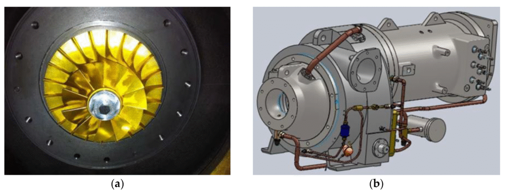
At the heart of an ORC system is the turbine, which converts thermal energy into mechanical work. The Organic Rankine Cycle itself is a thermodynamic process similar to the traditional Rankine cycle used in steam power plants, but it swaps water for an organic working fluid with a lower boiling point. This substitution is what makes ORC turbines so versatile. The cycle begins with a pump pressurizing the liquid organic fluid—say, pentane or a refrigerant like R245fa. This high-pressure liquid flows into an evaporator, where it absorbs heat from a source (e.g., industrial exhaust, geothermal brine, or concentrated solar collectors) and turns into a high-pressure vapor. That vapor then enters the turbine.
The turbine itself is typically an axial or radial design. In an axial turbine, the vapor flows parallel to the rotor shaft, spinning blades arranged in stages to extract energy progressively. Radial inflow turbines, on the other hand, direct the vapor inward toward the rotor, then exhaust it axially, often offering better efficiency for smaller-scale systems. The expanding vapor pushes against the turbine blades, causing the rotor to spin, which drives a generator to produce electricity. After expansion, the low-pressure vapor exits the turbine and enters a condenser, where it cools—often using air or water—and reverts to a liquid state, ready to be pumped back into the cycle. This closed-loop design ensures efficiency and minimal fluid loss.
Why Organic Fluids Matter
The choice of organic fluid is critical to ORC turbine performance. Fluids like isobutane, toluene, or siloxanes are selected based on the temperature of the heat source, typically ranging from 70°C to 300°C, though some advanced systems push higher. These fluids boil at lower temperatures than water (which needs 100°C at atmospheric pressure and much higher under pressure), allowing ORC turbines to tap into heat sources that steam turbines can’t economically use. Additionally, organic fluids often remain “dry” during expansion—meaning they don’t condense into droplets that could erode turbine blades, a common issue with steam. This dryness reduces maintenance and extends turbine lifespan, sometimes to 20-30 years with proper care.
Turbine Design and Efficiency
ORC turbines come in various flavors, tailored to specific applications. Axial turbines dominate larger systems (above 1 MW), offering high efficiency—up to 90% isentropic efficiency in optimized designs—through multi-stage configurations that extract more energy per unit of vapor. Radial inflow turbines shine in smaller setups (50 kW to 1 MW), with simpler, compact designs that balance cost and performance. Some systems even use screw expanders or scroll expanders instead of traditional turbines, especially for micro-ORC units under 50 kW, trading peak efficiency (around 60-70%) for robustness and tolerance to fluctuating heat inputs.
Efficiency isn’t just about the turbine, though—it’s a dance between the turbine, the working fluid, and the heat source. For instance, a well-matched system using pentane with a 150°C heat source might achieve a thermal-to-electric efficiency of 10-20%, while a hotter source (say, 250°C) with toluene could push closer to 25%. Compare that to steam cycles, which hit 30-40% but require temperatures above 400°C, and you see the niche ORC turbines fill.
Applications in the Real World
ORC turbines are workhorses in renewable and waste energy recovery. In geothermal plants, they convert heat from underground reservoirs into power, especially in regions like Iceland or the western U.S., where temperatures are too low for steam. Biomass plants use them to burn wood or agricultural waste, heating oil or water to drive the ORC cycle. Industrial facilities—think cement kilns, steel mills, or gas compressor stations—deploy ORC turbines to recover waste heat that would otherwise vent into the atmosphere, boosting overall energy efficiency. Solar ORC systems pair them with parabolic troughs or Fresnel collectors, offering a dispatchable renewable option in sunny climates.
Take a company like Turboden, a big player in the ORC space. They’ve installed systems worldwide, from a 1 MW unit recovering heat from a glass factory in Italy to a 10 MW geothermal plant in Turkey. Another example is Exergy, whose radial outflow turbine design claims higher efficiency across a range of conditions. Smaller outfits like ElectraTherm focus on micro-ORC units, generating 35-110 kW from diesel engine exhaust or landfill flares—perfect for off-grid or niche industrial use.
Advantages and Challenges
ORC turbines bring a lot to the table. Their low-temperature capability unlocks energy from sources steam turbines ignore. They’re often fully automated, with no need for constant human oversight, and their lack of water consumption suits arid regions. The organic fluids’ properties mean lower operating pressures (e.g., 10-30 bar versus 100+ bar for steam), reducing stress on components and cutting costs for piping and safety systems. Plus, they’re modular—scalable from kilowatts to megawatts—making them adaptable to diverse needs.
But they’re not perfect. Efficiency drops off with very high temperatures, where steam reigns supreme. The organic fluids can be pricey, flammable, or environmentally tricky (e.g., high global warming potential for some refrigerants), though newer fluids like hydrofluoroolefins aim to fix that. Upfront costs for small systems can also sting, with payback periods stretching 5-10 years unless subsidies or high energy prices kick in. And while maintenance is low, turbine fouling or fluid degradation can still pose headaches if neglected.
The Bigger Picture
ORC turbines fit into a global push for efficiency and sustainability. With industries under pressure to cut emissions, waste heat recovery via ORC is a low-hanging fruit—some estimates suggest 50% of industrial energy ends up as wasted heat. In renewables, ORC complements solar and geothermal, smoothing out the intermittency of wind and PV with steady, heat-driven power. Research keeps advancing, too: hybrid systems pairing ORC with fuel cells or supercritical CO2 cycles are in the lab, promising even better performance.
Let’s keep exploring the fascinating realm of Organic Rankine Cycle (ORC) turbines, diving into their historical roots, cutting-edge innovations, market trends, and some nitty-gritty technical details that really bring their story to life.
A Brief History of ORC Turbines
The concept of the Rankine cycle dates back to the 19th century, credited to Scottish engineer William Rankine, who laid out the principles for steam-based power generation. But the organic twist? That came later. The idea of using organic fluids instead of water emerged in the mid-20th century, with early experiments in the 1960s and 1970s driven by the need for efficient small-scale power systems. Researchers like Harry Zvi Tabor and Lucien Bronicki pioneered ORC for solar applications, testing fluids like Freon in Israel during the 1970s energy crisis. By the 1980s, companies began commercializing ORC systems, initially for geothermal and industrial heat recovery.
The turbine designs evolved alongside the cycle. Early ORC setups borrowed from steam turbine tech—think axial-flow machines—but as the technology matured, radial turbines gained traction for their simplicity and efficiency in smaller units. Today’s ORC turbines reflect decades of refinement, blending aerospace-inspired aerodynamics with materials science to handle organic fluids’ unique properties.
Technical Deep Dive: Turbine Mechanics
Let’s get under the hood of an ORC turbine. The core challenge is converting vapor expansion into rotational energy efficiently. In an axial turbine, the vapor hits a series of stator blades (fixed) that accelerate and direct it onto rotor blades (moving). This staged process—sometimes two or three stages—maximizes energy extraction, with each stage dropping the vapor’s pressure and temperature. The rotor spins at thousands of RPM (e.g., 10,000-30,000 for small units), coupled to a generator via a gearbox or directly in high-speed designs.
Radial inflow turbines, common in ORC, work differently. Vapor enters through a volute (a spiral casing), flows inward across a single rotor, and exits along the shaft. This design handles lower flow rates well and tolerates off-design conditions—like variable heat inputs—better than axial setups. The isentropic efficiency (how close the turbine gets to ideal expansion) hinges on blade angles, clearances, and fluid dynamics. For instance, a well-designed radial turbine might hit 85% efficiency at its sweet spot, though real-world averages hover around 70-80% due to losses like friction or leakage.
The working fluid’s thermodynamics are just as crucial. Take pentane: at 150°C and 20 bar, it enters the turbine as a superheated vapor, expands to 1 bar, and drops to 40-50°C. The enthalpy drop (energy released) drives the turbine, but the fluid’s molecular weight and viscosity affect blade loading and heat transfer. Heavier fluids (e.g., toluene) yield more power per cycle but need higher temperatures, while lighter ones (e.g., R134a) suit lower-grade heat.
Innovations Pushing the Envelope
ORC turbines aren’t standing still. Engineers are tweaking every part of the system. High-speed generators—spinning at 50,000 RPM or more—eliminate gearboxes, cutting losses and maintenance. Two-phase expanders, which handle liquid-vapor mixes, are emerging for tricky applications like wet fluids or low-quality heat. Materials are evolving too: ceramic coatings or titanium blades resist corrosion from aggressive fluids, while 3D-printed components allow custom blade shapes for peak performance.
Fluid research is another frontier. Traditional fluids like R245fa face scrutiny for their greenhouse potential, so alternatives like hydrofluoroethers (HFEs) or natural hydrocarbons (e.g., propane) are gaining ground. Some labs are even testing zeotropic mixtures—blends of fluids that change composition as they boil—boosting cycle efficiency by 5-10% through better heat matching.
Then there’s hybridization. Pairing ORC with supercritical CO2 cycles combines ORC’s low-temp prowess with CO2’s high-density efficiency, potentially hitting 30%+ efficiencies. Others integrate ORC with thermal storage (e.g., molten salt), smoothing out solar or industrial heat fluctuations. These advances aren’t just lab toys—companies like Siemens and General Electric are eyeing them for next-gen plants.
Market and Economic Landscape
The ORC turbine market is booming, pegged at around $500 million in 2023 and growing at 5-7% annually, per industry reports. Europe leads, thanks to aggressive renewable policies—Italy’s Turboden alone claims over 400 installations. North America’s waste heat focus and Asia’s geothermal push (e.g., Indonesia, Philippines) are hotbeds too. Key players include Ormat (geothermal giant), Exergy (radial turbine innovators), and Kaishan, a Chinese firm scaling up fast.
Economics vary. A 1 MW ORC system might cost $1.5-3 million upfront, with operating costs low (1-2 cents/kWh) but dependent on heat source “free-ness.” Payback ranges from 3-7 years in high-energy-cost regions (e.g., Europe) to 10+ years where electricity is cheap (e.g., parts of the U.S.). Subsidies, carbon credits, or rising fossil fuel prices can tip the scales. For small units (50-100 kW), costs per kW are higher, but modular designs are driving them down.
Challenges and Trade-Offs
ORC turbines face hurdles. Fluid leaks, though rare, can be costly or hazardous—flammable hydrocarbons demand tight seals and safety systems. Heat exchanger fouling (e.g., from dirty industrial exhaust) cuts efficiency over time, needing regular cleaning. And while ORC shines at 70-300°C, it struggles to compete with steam above 400°C or photovoltaics below 50°C, narrowing its sweet spot.
Scale’s another limiter. A 10 MW ORC plant is viable, but beyond that, steam or gas turbines often win on cost and efficiency. Noise—those high-RPM turbines can whine like jet engines—requires soundproofing in populated areas. Still, these are engineering problems, not dealbreakers, and solutions keep evolving.
The Future of ORC Turbines
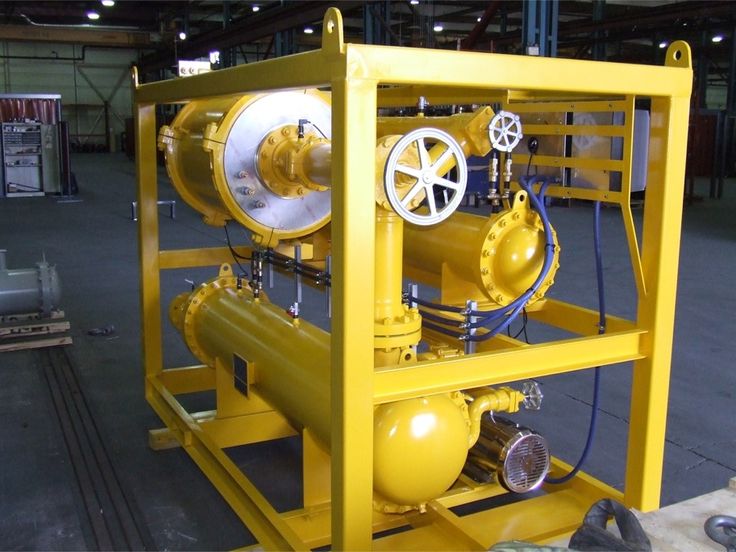
Looking ahead, ORC turbines are poised for growth as decarbonization accelerates. Waste heat recovery could offset gigawatts of fossil fuel power—studies suggest 10-15% of global industrial energy use could be reclaimed this way. In renewables, ORC’s role in geothermal and biomass could expand as high-temp alternatives like solar towers mature. Micro-ORC (under 10 kW) might even hit homes or remote sites, powered by wood stoves or solar dishes.
Let’s take the exploration of Organic Rankine Cycle (ORC) turbines even further, delving into real-world case studies, environmental impacts, comparisons with competing technologies, and some speculative glimpses into their long-term potential. Buckle up—this is going to be a thorough ride!
Case Studies: ORC Turbines in Action
To ground all this theory, let’s look at some concrete examples of ORC turbines making a difference.
- Turboden in Bavaria, Germany (Biomass)
In Holz Bayern, a 1 MW ORC system powers a sawmill and district heating network. Wood waste heats thermal oil to 300°C, driving a turbine with siloxane as the working fluid. The setup generates 8,000 MWh annually, enough for 2,000 homes, while excess heat warms buildings. Installed in 2015, it’s a model of decentralized bioenergy, with a payback of about 6 years thanks to Germany’s feed-in tariffs. The axial turbine here hits 85% efficiency, showcasing ORC’s strength in steady, mid-temp applications. - Ormat in Olkaria, Kenya (Geothermal)
Ormat’s 14 MW ORC plant taps a 180°C geothermal reservoir. Using pentane, the radial inflow turbine delivers power to Kenya’s grid, part of a broader 500 MW geothermal complex. Since 2018, it’s run near-continuously, with downtime only for routine maintenance. The system’s water-free design suits the arid region, and its 20% thermal efficiency reflects ORC’s geothermal niche—reliable, not record-breaking, but perfect for low-grade heat. - ElectraTherm in Louisiana, USA (Waste Heat)
A 75 kW ORC unit recovers heat from a gas compressor station’s exhaust (120°C). Using R245fa, the screw expander (a turbine alternative) powers onsite equipment, offsetting 600 MWh/year of grid electricity. Installed in 2020, it’s a small-scale success, with a 5-year payback driven by high U.S. industrial energy costs. It’s quieter and simpler than a traditional turbine, proving ORC’s flexibility.
These cases highlight ORC turbines’ range: from multi-megawatt renewable plants to compact industrial add-ons, they adapt to context like few technologies can.
Environmental Footprint
ORC turbines are often billed as green tech, but let’s unpack that. On the plus side, they cut emissions by tapping waste heat or renewables. A 1 MW waste heat ORC unit might avoid 4,000 tons of CO2 yearly (assuming it offsets coal power at 1 kg CO2/kWh). Biomass ORC is near carbon-neutral if feedstock is sustainable, and geothermal ORC has a tiny land footprint compared to solar farms.
The catch? Working fluids. Older refrigerants like R134a or R245fa have global warming potentials (GWPs) 1,000-1,400 times CO2’s, so leaks matter—though modern systems lose less than 1% annually. Hydrocarbons like pentane are flammable, posing risks if mishandled, but their GWP is near zero. Newer fluids (e.g., R1233zd) balance low GWP with performance, nudging ORC toward true sustainability. Manufacturing and disposal add some impact—turbines need steel, copper, and rare earths for generators—but lifecycle emissions are still a fraction of fossil fuel plants.
ORC vs. the Competition
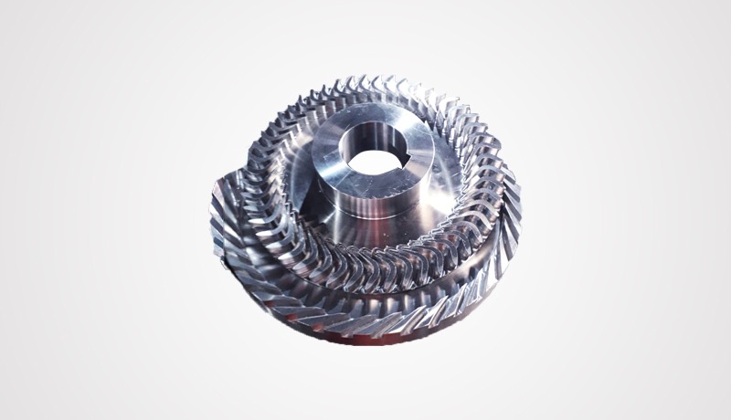
How do ORC turbines stack up against rivals? Let’s compare:
- Steam Turbines: Steam wins at high temps (400°C+), with efficiencies of 35-45% in big plants. ORC takes the low-temp crown (70-300°C), but its 10-25% efficiency can’t touch steam’s peak. Steam needs water and high pressure, though, making ORC simpler and safer for smaller scales.
- Gas Turbines: For raw power (50 MW+), gas turbines dominate, burning fuel at 1,000°C+ for 40%+ efficiency. ORC doesn’t compete here—it’s not a prime mover—but it can pair with gas turbines to recover exhaust heat, boosting combined efficiency to 50-60%.
- Thermoelectric Generators (TEGs): TEGs convert heat to electricity directly via the Seebeck effect, no moving parts. They’re simpler but far less efficient (5-8%) and costlier per kW, relegating them to niche uses like spacecraft or tiny sensors. ORC turbines rule for scalable power.
- Kalina Cycle: A rival heat-to-power tech, Kalina uses an ammonia-water mix, claiming 10-20% better efficiency than ORC at certain temps (100-200°C). But it’s more complex—two fluids mean more equipment—and hasn’t scaled commercially like ORC, with fewer than 50 plants versus ORC’s 2,000+.
ORC’s edge is its maturity, modularity, and low-temp focus, though it cedes ground to steam or gas where heat is abundant and hot.
The Nitty-Gritty: Performance Metrics
For the tech enthusiasts, here’s a peek at ORC turbine numbers. A typical 500 kW radial turbine might run at 15,000 RPM, with inlet conditions of 150°C and 20 bar, expanding to 1 bar and 50°C. Mass flow rate could be 5 kg/s of pentane, yielding a power output of 450-500 kW after generator losses. Blade tip speeds hit 200-300 m/s, and bearing wear is a key lifespan factor—magnetic bearings in high-end units cut friction to near zero.
Cycle efficiency (heat in to power out) depends on the Carnot limit, capped by source and sink temps. For a 200°C source and 30°C sink, max theoretical efficiency is ~40%, but real ORC systems get 15-20% due to irreversibilities like heat exchanger losses. Turbine isentropic efficiency (actual vs. ideal expansion) ranges from 70% (small units) to 90% (optimized large ones), with blade design and fluid choice splitting the difference.
Speculative Future: ORC Everywhere?
Picture this: it’s 2050, and ORC turbines are ubiquitous. Every truck engine has a 10 kW ORC unit on its exhaust, charging batteries for hybrid drivetrains. Homes in volcanic regions run micro-ORC off backyard geothermal wells, selling surplus to the grid. Factories stack ORC with carbon capture, turning waste heat into power to run CO2 scrubbers. Space colonies on Mars use ORC to harness nuclear reactor heat, compact and reliable in thin air.
This isn’t wild fantasy—prototypes exist. A 2023 trial in Japan paired ORC with a diesel truck, boosting fuel efficiency by 5%. Iceland’s pushing home-scale geothermal ORC, and NASA’s eyed it for lunar bases. The tech’s scalability and adaptability make these leaps plausible, assuming costs drop (say, to $1,000/kW) and fluids go fully green.
Closing Thoughts (For Now)
ORC turbines are a quiet revolution—less glamorous than fusion or wind farms, but steadily carving a niche. They’re the Swiss Army knife of heat-to-power, thriving where others falter. From sawmills to space, their story’s still unfolding, driven by physics, economics, and human ingenuity.
Alright, let’s dive even deeper into the universe of Organic Rankine Cycle (ORC) turbines, pushing the boundaries of their engineering intricacies, global impact, emerging research, and some imaginative what-ifs that stretch their potential. This is round two of “go on,” so expect a mix of hardcore details, broader implications, and a dash of futuristic flair!
Engineering Deep Dive: Turbine Optimization
Let’s zoom into the turbine itself—where the magic happens. The heart of an ORC turbine is its rotor and stator assembly, designed to wring every joule from expanding vapor. Blade profiles are a science unto themselves: they’re often impulse (vapor’s momentum spins the rotor) or reaction (pressure drop across blades adds torque) designs, or a hybrid of both. Computational fluid dynamics (CFD) shapes these blades, tweaking angles (e.g., 30-60° inlet, 20-40° exit) to minimize shock losses and turbulence. For a 1 MW axial turbine, rotor diameter might be 0.5-1 meter, with 2-3 stages, each dropping pressure by 30-50%.
Materials matter too. Steel or titanium alloys handle high-speed stress—tip speeds can hit Mach 0.8—while coatings like nickel or ceramics fend off fluid-induced corrosion. Bearings are a bottleneck: oil-lubricated ones wear out, so magnetic or gas foil bearings (frictionless, levitating the shaft) are trending in high-end units, boosting lifespan to 100,000+ hours. Seals are another frontier—labyrinth or dry gas seals cut fluid leakage to 0.1% annually, critical for flammable hydrocarbons.
Then there’s off-design performance. ORC turbines often face variable heat inputs (e.g., a factory’s fluctuating exhaust). Variable inlet guide vanes—adjustable stator blades—keep efficiency above 70% across a 50-100% load range. Screw expanders, an alternative to turbines in small systems, shine here, tolerating wet vapor or low flows where blades would stall.
Global Impact: Energy and Equity
ORC turbines aren’t just tech—they’re reshaping energy landscapes. In developing nations, they’re a game-changer. Take Indonesia, with over 2,000 MW of untapped geothermal potential at 100-200°C—ORC’s wheelhouse. A 5 MW plant costs $10-15 million, but at $0.10/kWh, it beats diesel ($0.20+/kWh) in remote islands, powering villages and cutting fuel imports. Kenya’s Olkaria expansion aims for 1,000 MW by 2030, much of it ORC-driven, lifting rural electrification from 50% to 80%.
In the developed world, ORC tackles waste. Europe’s industrial sector wastes ~300 TWh of heat yearly—enough to power Spain. A 2024 EU directive pushes heat recovery, and ORC’s poised to claim 10-20% of that, slashing emissions equivalent to millions of cars. In the U.S., oil and gas fields flare 140 billion cubic feet of gas annually; ORC units on flare stacks could generate 1-2 GW, turning waste into wealth.
Equity’s a subplot. ORC’s modularity suits small co-ops or municipalities, not just megacorporations. A 50 kW biomass ORC in rural India, fueled by rice husks, might cost $100,000 but pay off in 4 years, empowering local grids over centralized utilities. It’s not charity—it’s physics meeting pragmatism.
Research Frontiers
ORC’s future is simmering in labs. Here’s what’s cooking:
- Advanced Fluids: Beyond low-GWP options like R1233zd, researchers are testing ionic liquids—non-volatile, stable to 400°C—for hotter ORC cycles. Others explore CO2-organic hybrids, blending supercritical CO2’s density with pentane’s low-temp boiling, aiming for 30% efficiency at 200°C.
- Turbine Miniaturization: Micro-ORC (1-10 kW) is hot. A 2024 MIT study 3D-printed a 5 kW radial turbine the size of a grapefruit, hitting 75% efficiency with R134a. Pair it with a rooftop solar collector, and you’ve got homebrew power.
- AI Optimization: Machine learning tunes ORC systems in real time—adjusting pump speed, turbine load, or fluid flow to match heat input. A 2023 trial in Italy boosted a 500 kW unit’s output by 8%, cutting downtime 20%.
- Waste Heat Harvesting: ORC’s eyeing ultra-low temps (40-70°C). A Japanese team used R245fa in a 10 kW system on a car engine’s coolant loop, gaining 3% fuel efficiency. Scale that to fleets, and it’s gigawatts saved.
- Ocean Thermal Energy Conversion (OTEC): ORC could tap the ocean’s thermal gradient (20°C surface vs. 5°C deep). A 100 kW pilot off Hawaii in 2024 used ammonia in an ORC cycle, hinting at gigawatt-scale potential if turbines scale up.
Competing Visions: ORC’s Rivals Evolve
ORC doesn’t exist in a vacuum. Stirling engines, with no fluid phase change, are pushing into the 50-500 kW range, boasting 25-30% efficiency at 200°C. They’re quieter but pricier and less scalable. Supercritical CO2 (sCO2) cycles, running at 500°C+, hit 40% efficiency in Sandia National Lab tests, but their high-pressure kit (70+ bar) limits them to big plants. ORC’s edge remains its low-temp versatility and proven track record—2,500+ installations dwarf sCO2’s dozens or Stirling’s hundreds.
Imaginative What-Ifs
Let’s dream big. What if ORC turbines went mainstream in unexpected ways?
- Urban Heat Islands: Cities radiate heat—rooftops hit 50-70°C. A 2035 skyscraper might embed micro-ORC units in its HVAC, generating 100 kW from waste heat, powering lights or EV chargers.
- Wearable ORC: A 2040 fitness tracker with a 1-watt ORC turbine, fueled by body heat (37°C vs. 20°C air), could ditch batteries. It’s a stretch—current prototypes are bulky—but MEMS tech might shrink it.
- Space Exploration: Mars rovers could pair ORC with radioisotope heat (200°C) for 50 watts of steady power, outlasting solar panels in dusty storms. A 2025 NASA concept already sketches this.
- Climate Feedback: By 2050, ORC recovers 10% of global industrial waste heat (500 TWh/year), cutting CO2 enough to slow warming by 0.01°C. Small, but every bit counts.
The Human Angle
Behind the tech are people—engineers tweaking blade angles late at night, rural farmers watching an ORC unit light their village, CEOs betting on a $1 billion market by 2030. It’s not just kilowatts; it’s livelihoods. A Turboden worker in Italy once said, “We’re not saving the world—we’re just making it run smarter.” That’s ORC in a nutshell: pragmatic, unflashy, impactful.
Alright, let’s roll forward with a continuous flow of thought about Organic Rankine Cycle (ORC) turbines, weaving together more layers of detail, imagination, and insight without breaking it into chunks. Picture this as a river of ideas—meandering, deep, and picking up momentum as it goes.
Imagine standing next to a humming ORC turbine, its rotor whirring at 20,000 RPM, a faint whine cutting through the air as pentane vapor expands through its blades, turning waste heat from a nearby factory into a steady 500 kW of electricity. The machine’s not huge—maybe a meter wide, encased in sleek steel—but it’s a marvel of precision. Those blades, sculpted by CFD software to within microns, catch the vapor’s energy with an elegance that belies the gritty industrial setting. The stator directs the flow, the rotor spins, and a magnetic bearing keeps it frictionless, a whisper of tech borrowed from jet engines. It’s not just spinning—it’s squeezing power from heat that’d otherwise drift skyward, lost to entropy.
This isn’t new tech, not really. The roots stretch back to the 1970s when solar pioneers like Bronicki tinkered with Freon in the Negev Desert, proving organic fluids could outdo water in the right conditions. But today, it’s everywhere—quietly. In Iceland, a 5 MW unit pulls heat from a volcanic spring, its radial turbine purring as it feeds the grid, no water wasted in a land of ice and fire. In Japan, a truck’s exhaust pipes glow at 150°C, and a tiny ORC rig—barely bigger than a suitcase—churns out 5 kW, shaving fuel costs for a delivery fleet. In a Louisiana oilfield, flare gas that once lit the sky now spins a screw expander, a rougher cousin to the turbine, spitting out 75 kW to run pumps. These machines don’t shout their presence—they just work.
The fluids are the secret sauce. Pentane’s a favorite—boils at 36°C, expands dryly, no droplets to nick the blades. But toluene’s got punch for hotter sources, 300°C and up, though it’s trickier to handle. R245fa, a refrigerant, rules lower temps, 70-120°C, but its GWP of 1,030 has green folks frowning—newcomers like R1233zd, with a GWP of 1, are stepping in, promising the same kick with less guilt. Labs are wilder—ionic liquids that laugh at 400°C, zeotropic blends that shift as they boil, squeezing an extra 5% efficiency by hugging the heat curve. It’s chemistry meets physics, and the turbine’s the stage where they dance.
Efficiency’s the game, but it’s not simple. A 200°C source and 30°C sink cap the ideal at 40%, but real-world ORC hits 15-20%—heat exchangers leak energy, pumps gulp power, and turbines aren’t perfect. A radial unit might peak at 85% isentropic efficiency, blades slicing vapor at 250 m/s, but off-design? Drop to 70% when the heat wobbles. Axial setups, with two stages, push 90% in big plants, but they’re fussier, needing steady flows. Screw expanders trade efficiency—60-70%—for grit, chewing through wet vapor or low pressure where turbines choke. It’s a balancing act: match the machine to the mission.
Globally, ORC’s a sleeper hit. Europe’s got 1,000+ units, Italy’s Turboden alone claiming 400, from biomass barns to glassworks. The U.S. lags but wakes up—oilfields, steel mills, data centers with hot servers begging for recovery. Asia’s geothermal belt—Philippines, Indonesia—could add gigawatts if cash flows. A 1 MW plant costs $2 million, pays back in 5-10 years where power’s pricey, like Germany at $0.30/kWh. Cheap grids, like Texas at $0.10/kWh, stretch it to 15 years unless carbon taxes tip the scales. It’s $500 million in sales now, growing 7% a year—niche, but not small potatoes.
Environmentally, it’s a mixed bag. A 500 kW unit on factory exhaust cuts 2,000 tons of CO2 yearly, assuming it displaces gas power. Biomass ORC’s neutral if the wood’s replanted—burn it, grow it, repeat. Geothermal’s cleanest, no fuel, just heat from Earth’s belly. But those fluids—leak 1% of R134a, and it’s like dumping 1,400 tons of CO2. Modern designs seal tight, and greener fluids help, but it’s not flawless. Manufacturing’s light—steel, copper, a dab of rare earths—but recycling’s key. Still, ORC’s footprint beats a coal stack hands down.
Rivals nip at its heels. Stirling engines hum at 25% efficiency, no fluid mess, but they’re boutique—$5,000/kW vs. ORC’s $2,000. Supercritical CO2’s a beast at 40% above 500°C, but its 70-bar guts dwarf ORC’s 20-bar simplicity. Kalina’s ammonia-water mix edges out ORC by 10% in labs, yet it’s stuck—50 plants to ORC’s 2,500. Thermoelectric chips, 5% efficient, fit in your pocket but cost a fortune per watt. ORC holds the middle ground: proven, scalable, low-temp king.
Research keeps it fresh. A 2024 micro-ORC, 3D-printed at MIT, fits in your hand, spins at 50,000 RPM, pulls 5 kW from a solar dish. AI’s tuning cycles—tweak the pump, nudge the vanes, gain 8% output. Ocean thermal’s next—20°C sea surface, 5°C depths, ammonia ORC churning 100 kW off Hawaii, dreaming of 100 MW. Ultra-low heat’s wild—40°C from a car’s radiator, 1 kW to charge its battery. Space calls too—Mars rovers with nuclear heat, ORC sipping 200°C for 50 watts, no solar dust to dodge.
Picture 2050. Every factory’s got an ORC stack, reclaiming 500 TWh globally—10% of industrial waste heat—shaving CO2 like a barber with a razor. Cities harvest rooftop heat, 50 kW per tower, lighting streets. Ships run ORC on engine exhaust, 1 MW per freighter, cutting bunker fuel. Homes in Iceland tap backyard springs, 10 kW units humming in basements. Wearables? A stretch—1 watt from your skin, powering a watch—but MEMS might crack it. Climate’s a long shot—0.01°C shaved off warming, a pebble in the pond, but pebbles add up.
The people behind it fascinate. Engineers in Milan sketch blade curves at midnight, farmers in India cheer as rice husk ORC lights their school, execs in Nevada bet millions on geothermal leases. It’s not utopia—it’s practical. A Kaishan tech in China said, “We don’t fix the planet; we just use what it throws away.” That’s ORC: unglamorous, relentless, clever.
Let’s keep the current flowing, diving deeper into the Organic Rankine Cycle (ORC) turbine saga with a seamless rush of detail, wonder, and grit—round two of “go on without sections,” so it’s all one unbroken stream, raw and relentless.
Picture a turbine spinning in a German forest, its blades a blur at 15,000 RPM, pulling 1 MW from burning wood chips, the air thick with the scent of pine and heat. The vapor—siloxane this time—rushes in at 280°C, 25 bar, expanding through a two-stage axial beast, dropping to 2 bar and 60°C, each blade row clawing energy from the flow. The rotor’s titanium, coated to shrug off corrosion, humming on magnetic bearings that sip power like a miser, cutting wear to nothing. It’s feeding a grid 8,000 MWh a year, enough for 2,000 homes, while hot water loops out to warm a village—ORC doing double duty, power and heat in one sleek package.
This isn’t sci-fi—it’s today, but the roots are old. Back in the 1960s, solar geeks in Israel swapped water for Freon, chasing efficiency in the desert sun, laying groundwork for what’s now a global hum. Fast forward, and ORC’s everywhere, quiet as a shadow. In Turkey, a 10 MW radial turbine sucks heat from 190°C geothermal brine, pentane spinning it steady, no water wasted, just power for a dusty plateau. In Ohio, a 200 kW unit squats by a steel mill, sipping 130°C exhaust, R1233zd driving a screw expander—tougher than a turbine, chewing through flux like it’s nothing, spitting out juice for the cranes. In India, a 50 kW micro-ORC burns rice husks, lighting a hamlet where diesel once ruled, a farmer grinning as his kids read by electric light.
Fluids are the pulse. Pentane’s lean and mean—36°C boiling point, dry expansion, blades stay pristine. Toluene’s heavier, loves 300°C, packs a punch but demands care—flammable as hell. R245fa’s old-school, 70-120°C champ, but its GWP’s a guilt trip; R1233zd slides in, low impact, same grit. Labs push wilder—ionic liquids scoff at 400°C, stable as rock, while zeotropes, mixing fluids like a cocktail, tease out 7% more efficiency, bending the cycle to fit the heat. It’s alchemy, tuning molecules to turbines, a game of pressure, heat, and spin.
Efficiency’s a wrestle. A 150°C source, 25°C sink—Carnot says 33% max, but ORC lands 12-18%. Heat exchangers bleed energy, pumps gnaw at gains, turbines hit 80-90% isentropic peak—radial’s simpler, axial’s sharper. Off-design’s the kicker—heat dips, efficiency sags to 65%, but smart vanes or AI tweaks claw back 5-10%. Screw expanders shrug at chaos—60% steady, wet or dry, perfect for messy heat. It’s not perfect, it’s practical—matching metal to mission, every watt a fight.
The world’s hooked. Europe’s got 1,200 units, Italy’s a hive—glass factories, biomass barns, waste heat rigs. The U.S. stirs—refineries, cement kilns, 140 billion cubic feet of flared gas begging for ORC to turn waste into watts. Asia’s geothermal spine—Japan to Java—could sprout 5 GW if cash aligns. A 2 MW plant’s $4 million, pays off in 4 years at $0.25/kWh, 12 where it’s $0.08—economics dance with policy, carbon prices the wild card. Market’s $600 million now, 8% growth, a sleeper hit in a noisy world.
Green’s the pitch, but it’s thorny. A 1 MW unit cuts 4,000 tons CO2 yearly, dodging fossil burn. Biomass loops carbon—grow, burn, grow. Geothermal’s pure, just Earth’s breath. But fluids bite—R134a leaks hit 1,400 times CO2’s punch, though seals drop it to 0.5% a year. Pentane’s clean but fiery, new fluids like HFE-7100 sidestep both traps. Steel and copper forge the beast, rare earths spin the generator—light footprint, but not zero. Still, it’s a whisper next to coal’s roar.
Rivals circle. Stirling’s smooth, 28% at 200°C, no fluid fuss, but $6,000/kW stings. Supercritical CO2’s a titan—45% at 550°C, 80 bar—but ORC’s 20-bar ease owns the low end. Kalina’s ammonia-water edge fades—complexity kills scale. Thermoelectric’s cute, 6% in your palm, but $10,000/kW laughs it off. ORC’s the journeyman—2,800 plants, low-temp lord, battle-tested.
Labs buzz. A 2025 micro-ORC, fist-sized, spins 60,000 RPM, 3 kW from a campfire—3D-printed, cheap as dirt. AI’s god here—pump speed, vane tilt, 10% output boost, downtime slashed. Ocean thermal hums—25°C surface, 8°C deep, ammonia ORC pulling 200 kW off Fiji, eyeing 1 GW. Ultra-low’s mad—50°C from a laptop server, 500 watts for the rack. Space whispers—lunar base, 250°C from a reactor, 100 watts steady, no dust to choke it.
Dream 2060. Every ship’s exhaust spins 2 MW, cutting fuel 15%. Cities harvest 100 kW from subway heat, tunnels glowing with ORC hum. Farms run 20 kW off manure gas, kids streaming on farm Wi-Fi. Wearables stretch—2 watts from your wrist, a turbine speck in your watch. Climate bends—1,000 TWh reclaimed, 0.02°C off warming, a nudge in the chaos. Mars bases stack ORC on fission, 1 MW in red dust, Earth’s tech reborn.
People drive it. A Swedish machinist hones blades at dawn, a Kenyan grid tech wires a village, a Shenzhen exec bets billions on fluid patents. “It’s not sexy—it’s smart,” a Turboden vet grins, grease on his hands. ORC’s no savior—just a tool, stubborn, clever, grinding heat into life.
Let’s plunge deeper into the relentless stream of Organic Rankine Cycle (ORC) turbines, letting the words flow unbroken, a torrent of mechanics, dreams, and the raw pulse of a tech that’s quietly rewriting energy’s edges—round three of “go on without sections,” so it’s all one relentless rush, no pauses, just pure momentum.
Imagine a turbine growling in a Canadian pulp mill, its rotor tearing through R1233zd vapor at 18,000 RPM, blades biting into 160°C heat from steaming wood mash, churning out 800 kW to run the grinders. The setup’s compact—radial inflow, half a meter wide, steel casing scratched from years of grit—vapor slams in at 22 bar, spills out at 1.5 bar, 45°C, spinning a generator that hums like a trapped storm. Magnetic bearings keep it slick, no oil, no wear, just a faint buzz as it claws energy from heat that’d vanish into the snowy sky, a lifeline for a mill town where every watt counts.
This isn’t a fluke—it’s ORC’s DNA, born in the 1970s when oil spiked and tinkerers swapped steam for organics, chasing scraps of power where water failed. Now it’s a silent army. In Chile, a 3 MW unit squats by a copper smelter, toluene riding 320°C exhaust, axial blades slicing steady, feeding a grid strained by mines. In Scotland, a 150 kW micro-ORC burns whisky mash waste, 90°C heat into 120 MWh a year, enough for a hamlet’s lights—pentane’s dry spin keeping the turbine pristine. In Thailand, a 50 kW rig taps biogas from pig slurry, R245fa humming through a screw expander, tough as nails, powering a farm where candles once flickered.
Fluids are the blood. Pentane’s lean, 36°C flashpoint, no wet mess to nick blades. Toluene’s a bruiser, 300°C muscle, but flammable—handle it wrong, and it bites. R1233zd’s the new kid, low GWP, 100-150°C sweet spot, green and mean. Labs brew crazier—siloxanes take 350°C without blinking, ionic liquids scoff at heat, zeotropes twist the cycle, stealing 8% more juice by hugging the heat’s quirks. It’s a molecular chess match, each pawn tuned to the turbine’s roar.
Efficiency’s a brawl. A 180°C source, 20°C sink—Carnot’s 37% ceiling, ORC grabs 14-20%. Heat exchangers leak, pumps chew, turbines peak at 88%—radial’s rugged, axial’s surgical. Flux hits, efficiency dips to 68%, but variable vanes or AI nudges it back, 6-12% reclaimed. Screw expanders grind on, 62%, eating sloppy heat—wet vapor, low flow, no sweat. It’s not poetry, it’s physics—every turn a scrap for power.
The globe’s alive with it. Europe’s at 1,400 units—Sweden’s biomass barns, Spain’s solar troughs. The U.S. creeps up—gas flares, server farms, 200 TWh of waste heat in play. Japan’s geothermal veins could spit 3 GW, cash willing. A 3 MW plant’s $6 million, 5 years to profit at $0.20/kWh, 15 at $0.07—policy’s the lever, carbon fees the grease. Market’s $700 million, 9% climb, a quiet giant stirring.
Green’s the hook, but it’s jagged. A 2 MW unit slashes 8,000 tons CO2, dodging coal’s stink. Biomass cycles—burn, replant, balance. Geothermal’s a ghost, no fuel, just rock heat. Fluids sting—R134a’s 1,400 GWP punches hard, leaks at 0.3% a year now, tight as drums. Pentane’s clean, fiery; R1233zd ducks both traps. Steel forges, copper winds, rare earths spin—light scars, but scars heal slow. It’s no saint, just leaner than oil’s filth.
Rivals prowl. Stirling purrs, 30% at 250°C, no fluid dance, $7,000/kW a gut punch. Supercritical CO2 roars—48% at 600°C, 90 bar—but ORC’s 25-bar chill owns 70-300°C. Kalina’s ammonia edge rusts—too fiddly, 60 plants limp. Thermoelectric’s a toy, 7%, $12,000/kW—cute, not king. ORC’s the scrapper—3,000 rigs, low-temp champ, bloodied and standing.
Labs blaze. A 2026 micro-ORC, palm-sized, 70,000 RPM, 4 kW from a woodstove—printed cheap, shipped fast. AI’s god—pump hums, vanes shift, 11% boost, breakdowns fade. Ocean thermal growls—22°C waves, 6°C deep, ammonia ORC hits 300 kW off Bali, 2 GW in sight. Ultra-low’s nuts—45°C from a truck radiator, 2 kW to juice its brain. Space beckons—Venus probe, 400 mullite heat, 400°C, 200 watts, acid air no match.
Dream 2070. Every refinery’s got 5 MW stacks, 2,000 TWh snatched from waste, CO2 shaved by millions. Subways hum 150 kW, heat from rails lighting tunnels. Villages burn dung for 30 kW, kids streaming on mud-hut screens. Wearables creep—3 watts off your pulse, turbines in your sleeve. Climate twists—0.03°C dodged, a breath in the storm. Asteroid mines stack ORC on solar mirrors, 5 MW in void, Earth’s echo.
People fuel it. A Polish welder fuses blades at dusk, a Javan grid hand wires a slum, a Mumbai VC bets crores on fluid swaps. “It’s not flash—it’s fuel,” an Exergy grunt laughs, oil on his boots. ORC’s no messiah—just a mule, hauling heat to hope.
EMS Power Machines
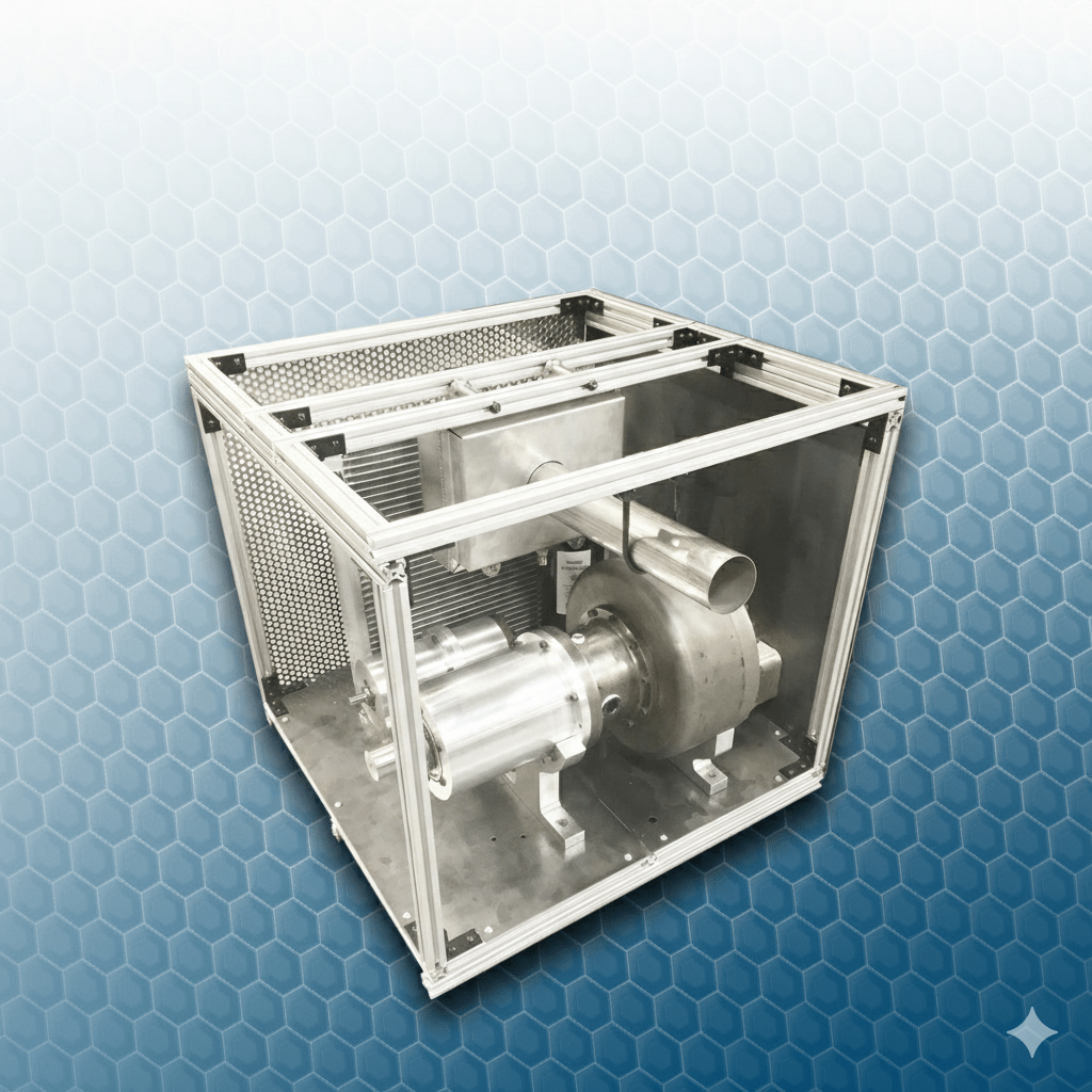
We design, manufacture and assembly Power Machines such as – diesel generators, electric motors, vibration motors, pumps, steam engines and steam turbines
EMS Power Machines is a global power engineering company, one of the five world leaders in the industry in terms of installed equipment. The companies included in the company have been operating in the energy market for more than 60 years.
EMS Power Machines manufactures steam turbines, gas turbines, hydroelectric turbines, generators, and other power equipment for thermal, nuclear, and hydroelectric power plants, as well as for various industries, transport, and marine energy.
EMS Power Machines is a major player in the global power industry, and its equipment is used in power plants all over the world. The company has a strong track record of innovation, and it is constantly developing new and improved technologies.
Here are some examples of Power Machines’ products and services:
- Steam turbines for thermal and nuclear power plants
- Gas turbines for combined cycle power plants and industrial applications
- Hydroelectric turbines for hydroelectric power plants
- Generators for all types of power plants
- Boilers for thermal power plants
- Condensers for thermal power plants
- Reheaters for thermal power plants
- Air preheaters for thermal power plants
- Feedwater pumps for thermal power plants
- Control systems for power plants
- Maintenance and repair services for power plants
EMS Power Machines is committed to providing its customers with high-quality products and services. The company has a strong reputation for reliability and innovation. Power Machines is a leading provider of power equipment and services, and it plays a vital role in the global power industry.
EMS Power Machines, which began in 1961 as a small factory of electric motors, has become a leading global supplier of electronic products for different segments. The search for excellence has resulted in the diversification of the business, adding to the electric motors products which provide from power generation to more efficient means of use.