We manufacture Steam turbines for sale. Steam turbine generator power machines for sale price from the manufacturer. High quality and low price with a guaranty
A steam turbine is a device that converts the thermal energy of steam into mechanical energy, which can then be used to generate electricity or perform mechanical work. Steam turbines are widely used in power plants, industries, and marine applications.
Here’s a basic overview of how a steam turbine works:
- Steam Generation: Steam is generated by heating water. This can be achieved by burning fossil fuels (coal, natural gas, oil), using nuclear reactions, or harnessing renewable energy sources like solar or geothermal.
- Expansion of Steam: The high-pressure steam produced in the boiler is directed into the steam turbine. The steam enters the turbine at a high velocity and pressure.
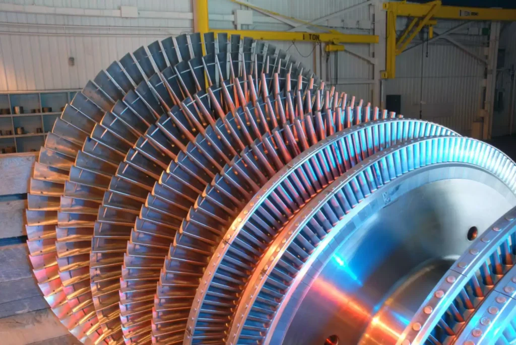
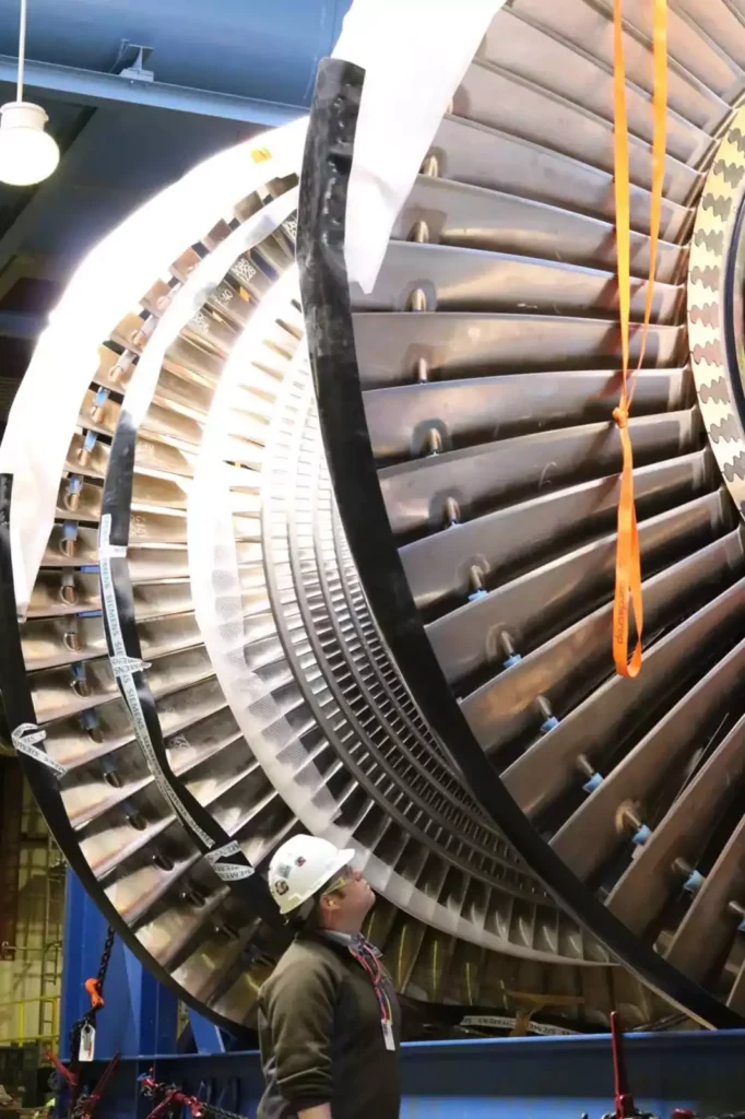
- Blades and Rotors: The steam flows through a series of blades mounted on rotors. As the steam passes over these blades, it causes the rotor to spin. The spinning rotor is connected to a shaft.
- Mechanical Work: The kinetic energy of the rotating rotor is converted into mechanical work. This work can be used to turn an electrical generator, drive machinery, or perform other tasks.
- Exhaust: After passing through the turbine blades, the steam exits the turbine at a lower pressure and temperature. This low-pressure steam is then condensed back into water and returned to the boiler to be reheated and used again.
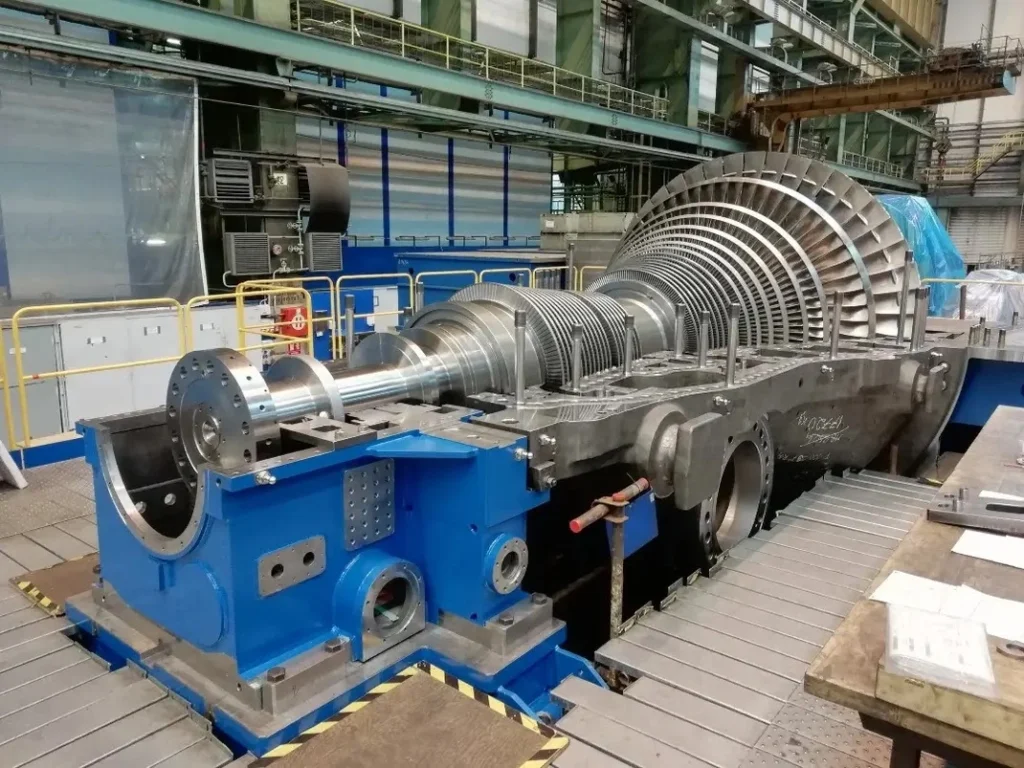
Steam Turbine
Steam turbines play a crucial role in a wide range of industrial applications, providing efficient and reliable power generation for various processes and equipment. Their versatility, durability, and ability to operate in demanding environments make them an essential component of modern industrial machinery.
At the forefront of this narrative is the intricate concept of steam condensation. In the world of steam turbine systems, condensation emerges as a crucial phase in the energy cycle. After steam has exerted its force to drive turbines and generate electricity, the phase of condensation comes into play. During this process, steam releases latent heat, a valuable resource that can be harnessed for various applications within a self-sufficient home. This utilization not only enhances the efficiency of energy conversion but also underscores the principle of extracting every available resource from the energy-producing process.
Zooming into the broader spectrum of energy storage solutions, the inclusion of steam storage becomes a cornerstone for self-sufficient homes. This innovative approach involves storing excess steam during periods of peak production for later use. Steam storage transforms homes into resilient energy hubs, capable of maintaining a continuous power supply even when external conditions are less favorable for immediate electricity generation. It introduces a dynamic element to energy management, aligning with the goal of creating homes that are adaptable and self-sustaining.
In the context of heating, ventilation, and air conditioning (HVAC) systems, the vision of steam-driven HVAC takes center stage. The integration of steam-driven technologies in HVAC systems revolutionizes climate control, offering an efficient and eco-friendly alternative. Steam-driven HVAC not only provides optimal temperature regulation but also aligns with the overarching goal of creating homes where every aspect of energy consumption is infused with sustainability. It signifies a departure from conventional HVAC methods, ushering in an era where heating and cooling are seamlessly integrated into a holistic, energy-efficient system.
As we navigate the expansive landscape of renewable energy, the utilization of geothermal steam introduces an element of environmental harmony. Geothermal steam, harnessed from the Earth’s internal heat, complements the self-sustaining energy home by providing a consistent and renewable energy source. This integration aligns with the principles of harnessing natural forces in a way that minimizes environmental impact and contributes to a holistic vision of sustainable energy generation. Geothermal steam epitomizes a synergy between the technological advancements of steam turbines and the Earth’s inherent energy reservoirs.
In the pursuit of harnessing the sun’s energy, the concept of solar steam generation emerges as a powerful ally. Solar steam generation systems utilize sunlight to produce steam, which can then be channeled into steam turbines for electricity generation. This synergy between solar and steam technologies epitomizes the integration of renewable sources, creating homes that draw energy from both the sun and steam to meet their power needs. It reflects a harmonious balance between cutting-edge technology and the natural abundance of solar energy.
The notion of steam-based heating extends beyond conventional applications, finding innovative use in processes such as steam curing for construction materials. This multifaceted application of steam-based heating illustrates its adaptability to various industries, promoting sustainable practices in sectors beyond electricity generation. It exemplifies a holistic approach where the benefits of steam technology extend into diverse realms of human activity, contributing to a future where energy is harnessed efficiently across various applications.
In the pursuit of efficiency, the integration of closed-loop steam systems becomes a defining characteristic of self-sustaining energy homes. Closed-loop systems minimize heat loss by containing and reusing steam within a controlled environment. This approach not only contributes to energy efficiency but also aligns with the broader goal of creating homes that operate with a mindful and resource-conscious ethos. It signifies a departure from open systems, emphasizing the need to maximize the utility of steam within a closed, sustainable loop.
The utilization of biomass steam generators signifies a marriage of renewable resources and steam technology. Biomass, derived from organic materials, can be used to produce steam for electricity generation in a sustainable and carbon-neutral manner. This application represents a harmonious relationship between technology and nature, contributing to the vision of homes powered by diverse and environmentally friendly energy sources. Biomass steam generators exemplify a holistic approach where the regeneration of resources is integrated into the energy generation process.
As the narrative extends to the realm of cooling, the concept of steam-powered cooling unfolds with a focus on efficient and environmentally conscious climate control. Steam-driven cooling systems, whether utilizing absorption or desiccant technology, provide an alternative to traditional air conditioning methods. This not only reduces energy consumption but also aligns with the broader vision of creating homes that prioritize comfort without compromising on sustainability. Steam-powered cooling signifies a departure from conventional cooling methods, showcasing the versatility of steam technology in enhancing overall energy efficiency.
In the context of transportation, the vision of steam-driven transportation comes full circle. Steam-powered vehicles, whether trains or other modes of transit, offer an alternative to traditional combustion engines. This application embodies the integration of steam technology into broader societal frameworks, showcasing its potential to redefine transportation in a way that minimizes environmental impact. Steam-driven transportation is a testament to the adaptability of steam power, extending its influence beyond stationary applications into the dynamic realm of mobility.
In summary, the fifth set of keywords unveils a panorama of self-sustaining energy homes where steam condensation, storage solutions, steam-driven HVAC, geothermal steam, solar steam generation, steam-based heating, closed-loop systems, biomass steam generators, steam-powered cooling, and steam-driven transportation converge to create a vision of homes that not only generate electricity sustainably but also integrate steam technologies into various facets of daily life and industry. Each keyword adds a layer to the narrative, showcasing the versatility and adaptability of steam power in shaping a future where energy is not just consumed but conscientiously crafted.
Key Characteristics of Steam Turbines in Industrial Applications:
- High Efficiency: Steam turbines are known for their high efficiency in converting thermal energy from steam into mechanical energy. This efficiency can reach up to 40%, making them a cost-effective and energy-efficient power source for industrial applications.
- Reliability and Durability: Steam turbines are designed to withstand the rigors of industrial use, operating continuously for extended periods with minimal maintenance. Their robust construction and proven technology make them a reliable and long-lasting power source.
- Scalability: Steam turbines can be scaled to meet the power requirements of a wide range of industrial applications, from small-scale processes to large-scale power plants. Their adaptable design allows for flexibility in power generation capacity.
- Adaptability to Various Fuels: Steam turbines can be driven by steam generated from a variety of fuels, including fossil fuels, biomass, and geothermal energy. This flexibility allows them to adapt to different industrial settings and fuel availability.
- Environmentally Friendly Alternative: Compared to internal combustion engines, steam turbines produce lower emissions of greenhouse gases and pollutants. This makes them a more environmentally friendly option for power generation in industrial applications.
Applications of Steam Turbines in Various Industrial Sectors:
- Power Generation: Steam turbines are widely used in power plants to generate electricity for industrial facilities, commercial buildings, and residential areas. Their ability to produce large amounts of electricity makes them a cornerstone of modern power generation systems.
- Cogeneration Plants: Cogeneration plants simultaneously generate electricity and steam for industrial processes. Steam turbines are a crucial component of cogeneration systems, as they efficiently convert thermal energy into both electricity and steam.
- Marine Propulsion: Steam turbines have traditionally been used to propel ships and other marine vessels. Their high power-to-weight ratio and adaptability to various fuel sources make them a viable option for marine propulsion systems.
- Mechanical Drive Applications: Steam turbines are used to drive a variety of mechanical equipment in industrial settings, such as pumps, compressors, and blowers. Their ability to provide rotational power makes them versatile for various mechanical drive applications.
- District Heating Systems: Steam turbines are employed in district heating systems to generate steam for heating buildings and homes. Their efficient steam production contributes to the overall efficiency and cost-effectiveness of district heating systems.
Future Trends in Steam Turbine Technology for Industrial Applications:
- Advanced Materials and Manufacturing Techniques: The development of advanced materials and manufacturing techniques is leading to steam turbines with higher efficiency, durability, and reduced maintenance requirements.
- Integration with Smart Grid Technologies: Steam turbine technology is being integrated with smart grid technologies, enabling real-time monitoring, optimization, and control of power generation in response to grid demand and renewable energy integration.
- Hybrid Power Systems: Steam turbines are increasingly being integrated with other power generation sources, such as renewable energy systems, to create hybrid power systems that offer improved efficiency, flexibility, and environmental benefits.
- Digitalization and Automation: Digitalization and automation are transforming the operation and maintenance of steam turbines, providing real-time data analytics, predictive maintenance capabilities, and remote monitoring for enhanced performance and reliability.
- Reduced Emissions and Environmental Impact: Ongoing research and development efforts focus on reducing emissions and the environmental impact of steam turbines, including advancements in carbon capture and storage technologies.
Conclusion:
Steam turbines remain a crucial component of modern industrial applications, providing efficient, reliable, and scalable power generation solutions. Their adaptability to various fuels, ability to integrate with other power sources, and potential for further advancements make them a valuable asset for the future of industrial power generation.
What is a Steam Turbine?
Steam turbines have been a cornerstone of industrial power generation for over a century, providing a reliable and efficient means of converting thermal energy into mechanical energy. As a critical component in electricity generation and various industrial processes, steam turbines play a pivotal role in the global energy landscape. Their ability to operate at high efficiencies and adapt to a wide range of applications has made them indispensable in sectors ranging from power plants to petrochemical industries.
The purpose of this article is to provide an in-depth exploration of steam turbines, focusing on their design, operation, and applications, as well as the latest technological advancements shaping their development. Targeted towards professionals in the field, this comprehensive guide aims to enhance understanding and facilitate informed decision-making in the deployment and management of steam turbine technology.
This article will delve into the historical evolution of steam turbines, examining the key milestones that have defined their progress. It will discuss the fundamental principles underlying their operation, including the thermodynamic processes and mechanical components that drive their performance. The article will also categorize different types of steam turbines, highlighting their specific applications and advantages.
Furthermore, this guide will address the benefits and drawbacks of steam turbines, providing a balanced perspective on their environmental and economic impacts. Recent innovations and future trends in steam turbine technology will be explored, offering insights into the direction of ongoing research and development.
In addition to technical aspects, the article will discuss the operational challenges and maintenance requirements associated with steam turbines, underscoring the importance of proper upkeep in ensuring their longevity and efficiency. By examining case studies of turbine failures and recoveries, readers will gain valuable insights into best practices and strategies for overcoming common obstacles.
Overall, this article aims to serve as a valuable resource for professionals seeking to deepen their knowledge of steam turbines and their role in modern power generation and industrial processes.
History of Steam Turbines
The history of steam turbines dates back to the late 19th century, a period marked by significant innovation and industrial growth. The development of steam turbines was driven by the need for more efficient power generation methods, as traditional steam engines were limited in their efficiency and capacity. This section will explore the historical milestones and key figures that have shaped the evolution of steam turbines over the years.
Early Development and Pioneers
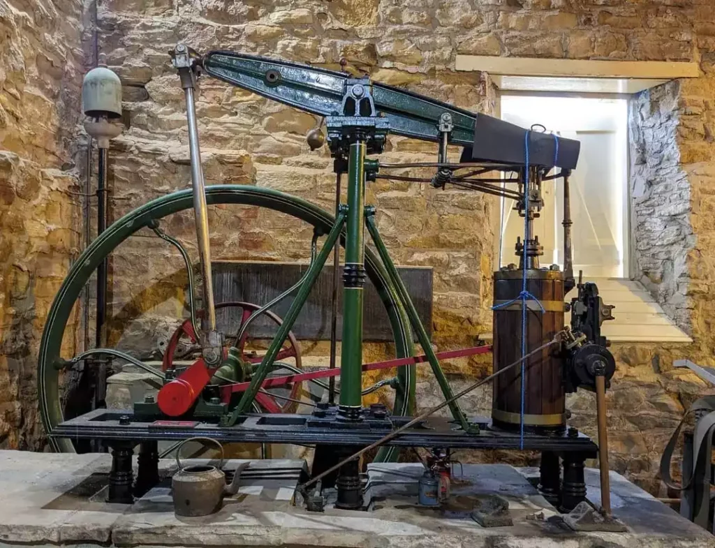
The concept of using steam to perform mechanical work has ancient roots, with early devices such as the Aeolipile, invented by Hero of Alexandria in the 1st century AD, demonstrating the potential of steam power. However, it wasn’t until the 19th century that steam technology began to advance rapidly, leading to the development of the steam turbine.
Sir Charles Parsons is credited with the invention of the modern steam turbine in 1884. Parsons’ design utilized a series of rotating blades to convert steam energy into rotational motion, a significant improvement over the reciprocating steam engines of the time. His invention revolutionized power generation, offering greater efficiency and higher power output. Parsons’ steam turbine was first demonstrated in 1897 aboard the Turbinia, a steam-powered ship that showcased the potential of this new technology.
In parallel, Swedish engineer Gustaf de Laval developed an impulse steam turbine in 1883, which used a high-velocity steam jet to strike blades attached to a rotor. De Laval’s design was particularly suited for applications requiring high rotational speeds, such as in centrifugal pumps and small-scale power generation.
Evolution Over the 20th Century
The early 20th century saw rapid advancements in steam turbine technology, driven by the increasing demand for electricity and the expansion of industrial activities. Steam turbines quickly became the preferred choice for power generation due to their superior efficiency and ability to operate continuously under high loads.
One of the key developments during this period was the introduction of the reaction turbine by Sir Charles Parsons. Unlike impulse turbines, which rely on steam jets to impart momentum to the blades, reaction turbines utilize the pressure difference across the blades to produce rotational motion. This design allowed for more efficient energy conversion and became widely adopted in large power plants.
The expansion of the electricity grid and the growth of industries such as steel production, chemical manufacturing, and transportation further fueled the demand for steam turbines. Advances in materials science, such as the development of high-strength alloys, enabled turbines to operate at higher temperatures and pressures, enhancing their performance and reliability.
Key Technological Milestones
Several key technological milestones have marked the evolution of steam turbines over the decades:
- Supercritical Steam Conditions: The introduction of supercritical steam conditions in the mid-20th century represented a significant leap in turbine efficiency. By operating at pressures and temperatures above the critical point of water, supercritical turbines achieved higher thermal efficiencies and reduced fuel consumption.
- Combined Cycle Power Plants: The integration of steam turbines into combined cycle power plants, where waste heat from gas turbines is used to produce steam, further improved overall plant efficiency. This approach maximized energy extraction from fuel and minimized environmental impact.
- Nuclear Power Generation: The advent of nuclear power in the mid-20th century presented new opportunities for steam turbine technology. Nuclear reactors produce large quantities of steam, making steam turbines an ideal choice for electricity generation in nuclear power plants.
- Digital Control Systems: The incorporation of digital control systems in the late 20th century enhanced the operational efficiency and reliability of steam turbines. Advanced monitoring and control technologies allowed for precise regulation of turbine parameters, optimizing performance and reducing downtime.
Basic Principles of Operation
Steam turbines operate on the principles of thermodynamics, converting thermal energy from steam into mechanical energy through a series of carefully designed processes. This section will explore the fundamental principles underlying steam turbine operation, including the thermodynamic cycles and the types of turbines commonly used in various applications.
Thermodynamics of Steam Turbines
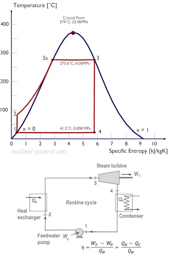
At the core of steam turbine operation lies the conversion of thermal energy into mechanical work. This process is governed by the laws of thermodynamics, which describe the relationships between heat, work, and energy. Steam turbines primarily operate based on the Rankine cycle, a thermodynamic cycle that involves the following key processes:
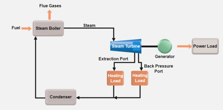
- Boiler (Heat Addition): In the boiler, water is heated to produce high-pressure steam. This steam is the primary energy source for the turbine and is typically superheated to increase efficiency.
- Turbine (Expansion and Work Extraction): The high-pressure steam is directed into the turbine, where it expands and imparts its energy to the turbine blades. As the steam expands, it undergoes a decrease in pressure and temperature, causing the turbine rotor to spin and produce mechanical work.
- Condenser (Heat Rejection): After passing through the turbine, the low-pressure steam is condensed back into water in the condenser. This process removes excess heat from the system and allows the water to be reused in the cycle.
- Pump (Pressurization): The condensed water is pumped back to high pressure and returned to the boiler, completing the cycle.
The efficiency of a steam turbine is influenced by factors such as steam pressure, temperature, and the effectiveness of the condensation process. By optimizing these parameters, engineers can maximize the energy conversion efficiency and minimize losses.
Types of Steam Turbines
Steam turbines are broadly categorized into two main types: impulse turbines and reaction turbines. Each type operates on distinct principles and is suited to specific applications.
- Impulse Turbines: In an impulse turbine, high-velocity steam jets are directed onto the turbine blades, causing them to rotate. The steam pressure remains constant across the blades, and energy is transferred primarily through the change in steam velocity. Impulse turbines are often used in applications requiring high rotational speeds, such as small-scale power generation and marine propulsion.
- Reaction Turbines: Reaction turbines, on the other hand, utilize the pressure drop across the blades to produce rotational motion. As steam flows through the blades, it experiences a change in both pressure and velocity, resulting in a more continuous energy transfer. Reaction turbines are commonly used in large power plants and industrial applications due to their higher efficiency and ability to handle large steam volumes.
The Rankine Cycle
The Rankine cycle is the thermodynamic cycle that underpins the operation of steam turbines. It consists of a series of processes that convert thermal energy into mechanical work, and its efficiency is a key determinant of overall turbine performance. The Rankine cycle is characterized by four main stages:
- Isentropic Expansion: In the turbine, high-pressure steam undergoes isentropic expansion, where its energy is converted into mechanical work. This process is adiabatic, meaning no heat is transferred to or from the system.
- Isobaric Heat Rejection: After expansion, the low-pressure steam enters the condenser, where it undergoes isobaric heat rejection. The steam is cooled and condensed into liquid water, releasing heat to the surroundings.
- Isentropic Compression: The condensed water is then pumped back to high pressure in the feed pump, undergoing isentropic compression. This process is also adiabatic and increases the pressure of the water without adding heat.
- Isobaric Heat Addition: Finally, the high-pressure water is returned to the boiler, where it undergoes isobaric heat addition. The water is heated and converted into high-pressure steam, completing the cycle.
The efficiency of the Rankine cycle is influenced by factors such as the temperature and pressure of the steam, the effectiveness of the condenser, and the degree of superheating. Engineers strive to optimize these parameters to maximize the efficiency of steam turbines and minimize fuel consumption.
Design and Components
The design of steam turbines is a complex engineering endeavor that involves the integration of various components and materials to achieve optimal performance and reliability. This section will explore the key design elements and components of steam turbines, highlighting the challenges and considerations involved in their construction.
Major Components
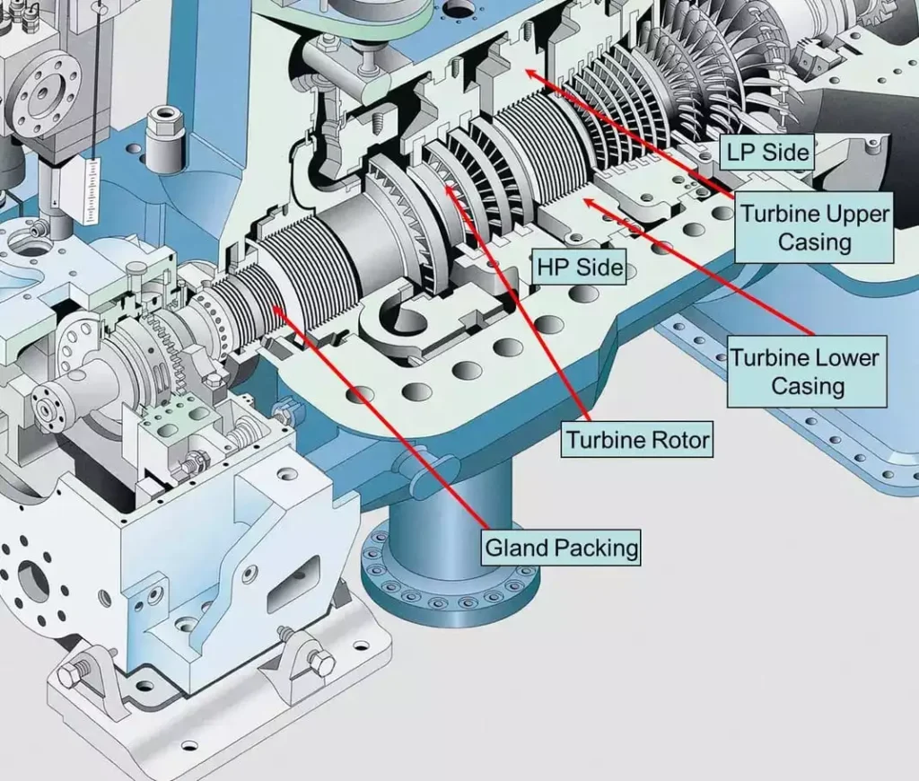
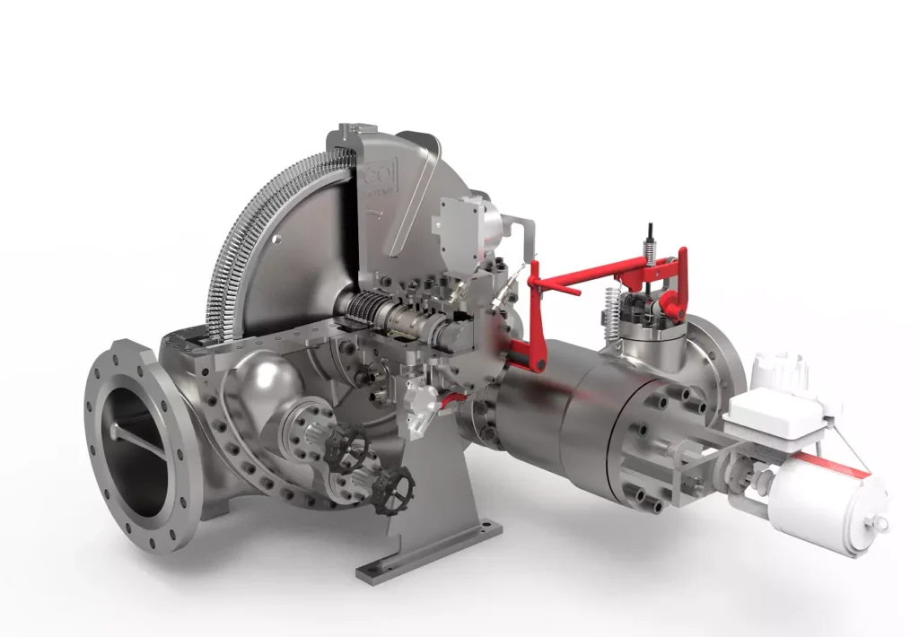
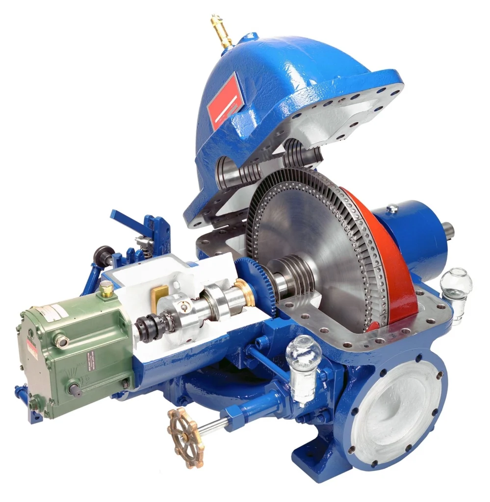
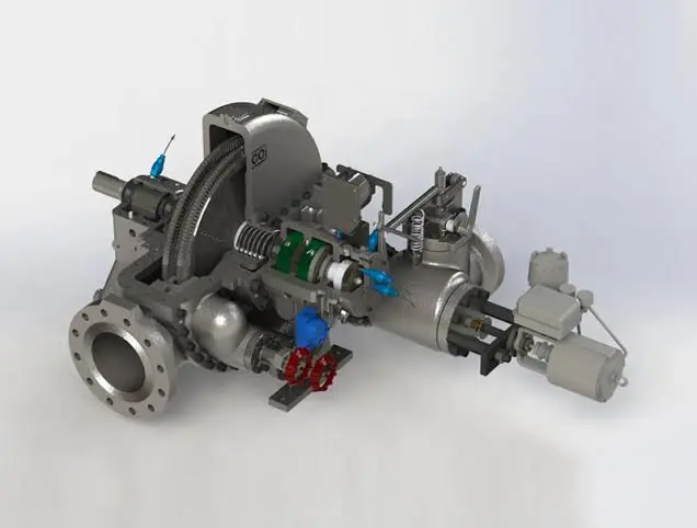
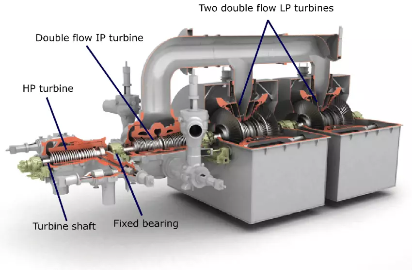
Steam turbines are comprised of several critical components, each playing a vital role in the conversion of thermal energy into mechanical work. The major components of a steam turbine include:
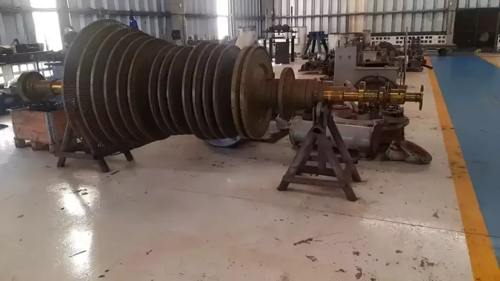
- Rotor: The rotor is the central shaft that supports the turbine blades and transmits the mechanical energy generated by the steam. It is typically made of high-strength materials, such as forged steel, to withstand the stresses and temperatures encountered during operation.
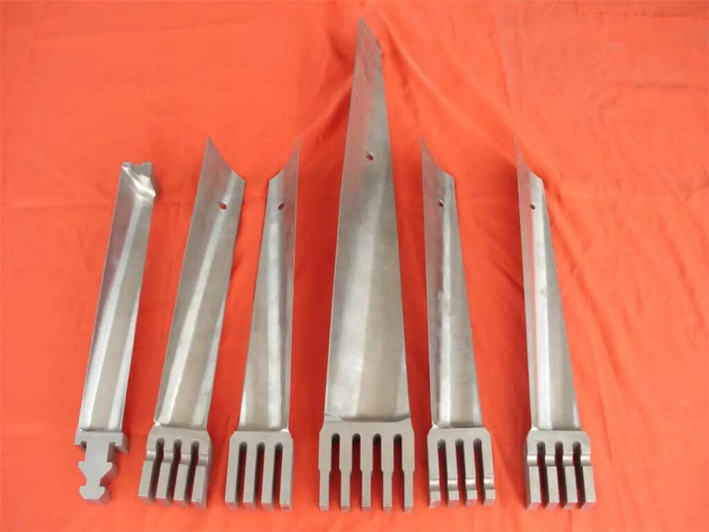
- Blades: The blades, also known as buckets or vanes, are the airfoil-shaped components that interact with the steam flow to produce rotational motion. Blades are carefully designed to maximize energy extraction while minimizing losses due to friction and turbulence.
- Casing: The casing, or housing, encloses the turbine and directs the flow of steam through the blades. It provides structural support and helps maintain the desired pressure and temperature conditions within the turbine.
- Nozzles: In impulse turbines, nozzles are used to direct high-velocity steam jets onto the turbine blades. The design of nozzles is critical to achieving the desired steam velocity and flow characteristics.
- Bearings: Bearings support the rotor and allow it to rotate smoothly with minimal friction. They are typically designed to handle both radial and axial loads and are lubricated to reduce wear and heat generation.
- Governor: The governor is a control mechanism that regulates the turbine’s speed and output by adjusting the steam flow. It ensures that the turbine operates within safe and efficient parameters, responding to changes in load demand and system conditions.
Materials Used in Construction
The materials used in the construction of steam turbines are chosen based on their ability to withstand high temperatures, pressures, and mechanical stresses. Key material considerations include:
- High-Temperature Alloys: Turbine components exposed to high temperatures, such as blades and rotors, are often made from nickel-based or cobalt-based superalloys. These materials exhibit excellent strength and resistance to creep, oxidation, and corrosion at elevated temperatures.
- Stainless Steel: Stainless steel is commonly used for turbine casings and other structural components due to its corrosion resistance and durability.
- Titanium: Titanium alloys are sometimes used in turbine blades for their high strength-to-weight ratio and resistance to fatigue and corrosion.
- Ceramics and Composites: Advanced ceramics and composite materials are being explored for use in steam turbines to improve efficiency and reduce weight. These materials offer potential benefits in terms of thermal insulation and resistance to wear.
Design Considerations and Challenges
The design of steam turbines involves several complex considerations and challenges that must be addressed to achieve optimal performance and reliability. Key design factors include:
- Thermal Efficiency: Maximizing thermal efficiency is a primary goal in turbine design. This involves optimizing the thermodynamic cycle, minimizing losses due to friction and turbulence, and maximizing energy extraction from the steam.
- Mechanical Stress and Fatigue: Turbine components are subjected to high mechanical stresses and cyclic loading during operation. Engineers must carefully analyze stress distributions and fatigue life to ensure the durability and reliability of the turbine.
- Vibration and Noise: Vibration and noise can impact the performance and lifespan of steam turbines. Design strategies such as balancing, damping, and noise reduction measures are employed to mitigate these effects.
- Cooling and Heat Management: Effective cooling and heat management are essential to prevent overheating and ensure the safe operation of the turbine. This involves the design of cooling systems, such as steam or air cooling, and the selection of materials with appropriate thermal properties.
- Environmental Impact: Minimizing the environmental impact of steam turbines is an important consideration. This includes reducing emissions, improving efficiency, and designing for recyclability and sustainability.
Types of Steam Turbines
Steam turbines are classified into various types based on factors such as size, application, and design characteristics. This section will explore the different types of steam turbines, highlighting their specific features and applications.
Classification by Size and Application
Steam turbines are broadly categorized into three main types based on their size and application:
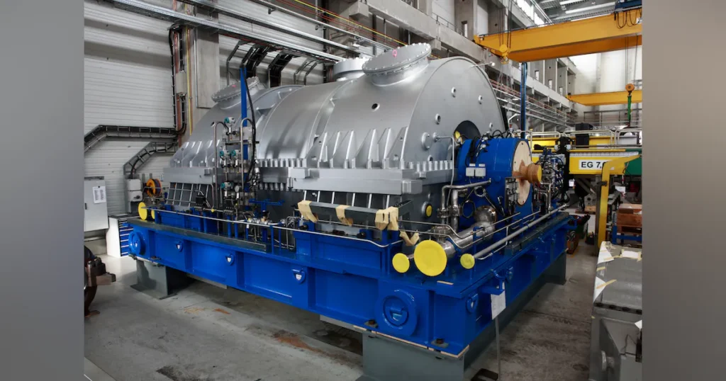
- Industrial Steam Turbines: Industrial steam turbines are typically used in manufacturing and process industries for power generation and mechanical drive applications. They range in size from small units producing a few kilowatts to large turbines generating several megawatts. Industrial turbines are often designed for flexibility, allowing them to operate efficiently under varying load conditions.
- Utility Steam Turbines: Utility steam turbines are large-scale turbines used in power plants to generate electricity for the grid. They are designed for high efficiency and reliability, with capacities ranging from hundreds of megawatts to over a gigawatt. Utility turbines are often part of combined cycle power plants, where they work in conjunction with gas turbines to maximize energy output.
- Specialized Steam Turbines: Specialized steam turbines are designed for specific applications, such as geothermal, nuclear, and marine propulsion. These turbines are tailored to the unique conditions and requirements of their respective industries, such as handling corrosive steam in geothermal plants or operating in a compact space on a ship.
Industrial Steam Turbines
Industrial steam turbines are versatile machines used in a wide range of applications, including:
- Cogeneration and Combined Heat and Power (CHP) Systems: Industrial turbines are often used in cogeneration and CHP systems, where they generate electricity and provide process heat for industrial facilities. This approach improves energy efficiency and reduces waste.
- Mechanical Drives: Steam turbines are used as mechanical drives for equipment such as compressors, pumps, and fans in industries such as oil and gas, petrochemicals, and pulp and paper.
- District Heating: In district heating systems, industrial turbines generate electricity and provide steam for heating residential and commercial buildings. This integrated approach enhances energy utilization and reduces emissions.
Utility Steam Turbines
Utility steam turbines are the backbone of power generation in many countries, providing reliable and efficient electricity to the grid. Key features of utility turbines include:
- High Efficiency: Utility turbines are designed for maximum efficiency, with advanced blade designs and optimized thermodynamic cycles. This allows them to extract the maximum amount of energy from the steam and reduce fuel consumption.
- Load Flexibility: Utility turbines are capable of operating under varying load conditions, allowing them to respond to fluctuations in electricity demand. This flexibility is essential for maintaining grid stability and reliability.
- Combined Cycle Operation: Many utility turbines are part of combined cycle power plants, where they work in tandem with gas turbines to maximize energy output and minimize emissions. In this configuration, waste heat from the gas turbine is used to produce steam for the steam turbine, enhancing overall plant efficiency.
Specialized Steam Turbines
Specialized steam turbines are designed to meet the unique requirements of specific industries and applications. Examples include:
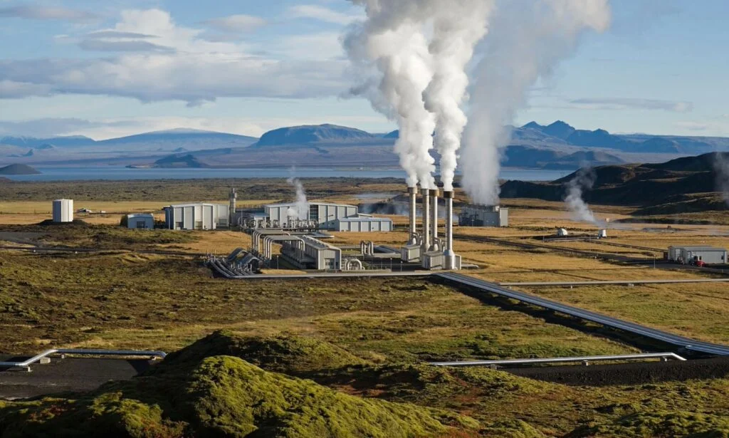
- Geothermal Steam Turbines: Geothermal turbines are designed to operate with steam extracted from geothermal reservoirs, which often contains corrosive impurities. These turbines are built with materials and coatings that resist corrosion and scaling.
- Nuclear Steam Turbines: Nuclear turbines are used in nuclear power plants to convert steam produced by nuclear reactors into electricity. They are designed to handle the high pressures and temperatures associated with nuclear steam and are subject to stringent safety and regulatory requirements.
- Marine Steam Turbines: Marine turbines are used for propulsion in ships and submarines. They are designed for compactness and reliability, with features such as gear reduction systems to optimize performance in marine environments.
Applications of Steam Turbines
Steam turbines are employed in a wide range of applications across various industries, owing to their versatility and efficiency. This section will explore the diverse applications of steam turbines, highlighting their role in power generation, industrial processes, and other sectors.
Power Generation in Different Sectors
Steam turbines are a cornerstone of power generation, providing reliable and efficient electricity for residential, commercial, and industrial use. Key applications in power generation include:
- Fossil Fuel Power Plants: Steam turbines are widely used in fossil fuel power plants, where they convert heat energy from burning coal, oil, or natural gas into electricity. These plants are a major source of electricity in many countries and are equipped with advanced turbines designed for high efficiency and low emissions.
- Nuclear Power Plants: In nuclear power plants, steam turbines convert heat generated by nuclear fission into electricity. The turbines used in these plants are designed to withstand the high temperatures and pressures associated with nuclear steam and are subject to rigorous safety and regulatory standards.
- Renewable Energy Sources: Steam turbines are also used in renewable energy applications, such as geothermal and biomass power plants. In geothermal plants, steam extracted from underground reservoirs is used to drive turbines and generate electricity. In biomass plants, steam produced from burning organic materials powers turbines for electricity generation.
Use in Combined Heat and Power (CHP) Systems
Combined Heat and Power (CHP) systems, also known as cogeneration, are an efficient method of generating electricity and useful heat simultaneously. Steam turbines play a crucial role in CHP systems by providing the mechanical energy needed for electricity generation while also supplying steam for heating and industrial processes. Applications of CHP systems include:
- Industrial Facilities: CHP systems are commonly used in industrial facilities, where they provide electricity and process steam for manufacturing operations. This integrated approach enhances energy efficiency and reduces waste, leading to cost savings and environmental benefits.
- District Heating: In district heating systems, steam turbines generate electricity and provide steam for heating residential and commercial buildings. This approach improves energy utilization and reduces emissions, contributing to sustainable urban development.
- Hospitals and Universities: CHP systems are used in hospitals and universities to provide reliable electricity and heating. The ability to generate both power and heat from a single fuel source enhances energy security and reduces operational costs.
Role in Industrial Processes
Steam turbines are integral to a variety of industrial processes, where they provide mechanical power and heat for manufacturing and processing operations. Key applications in industrial processes include:
- Petrochemical Industry: In the petrochemical industry, steam turbines drive compressors, pumps, and other equipment used in the production and refining of chemicals and fuels. The high efficiency and reliability of steam turbines make them well-suited for demanding industrial applications.
- Pulp and Paper Industry: Steam turbines are used in the pulp and paper industry to generate electricity and provide steam for the pulping and drying processes. The use of steam turbines in these operations enhances energy efficiency and reduces environmental impact.
- Food and Beverage Industry: Steam turbines are employed in the food and beverage industry to provide power and steam for cooking, sterilization, and other processes. The ability to integrate steam turbines into cogeneration systems allows for efficient energy utilization and cost savings.
Advantages and Disadvantages
Steam turbines offer numerous advantages in terms of efficiency, reliability, and versatility, but they also have certain disadvantages and limitations. This section will provide a balanced perspective on the advantages and disadvantages of steam turbines, comparing them with other power generation technologies.
Advantages of Steam Turbines
- High Efficiency: Steam turbines are known for their high efficiency in converting thermal energy into mechanical work. Advanced designs and materials have enabled turbines to achieve thermal efficiencies exceeding 40% in modern power plants.
- Reliability and Durability: Steam turbines are highly reliable and durable, with the ability to operate continuously under high loads for extended periods. Their robust construction and materials ensure long service life and minimal maintenance requirements.
- Versatility: Steam turbines are versatile machines that can be used in a wide range of applications, from power generation to industrial processes. Their ability to operate with various fuel sources, including fossil fuels, nuclear, and renewable energy, makes them adaptable to different energy landscapes.
- Low Emissions: Steam turbines can achieve low emissions when used in combination with advanced combustion and emission control technologies. Combined cycle power plants, for example, utilize steam turbines to reduce greenhouse gas emissions and improve overall plant efficiency.
- Scalability: Steam turbines are available in a wide range of sizes and capacities, making them suitable for both small-scale and large-scale applications. This scalability allows for flexible deployment in diverse industries and settings.
Disadvantages of Steam Turbines
- Complexity and Cost: The design and construction of steam turbines involve complex engineering and high costs. The need for specialized materials, precision manufacturing, and advanced control systems contributes to the overall expense of turbine installation and maintenance.
- Start-up Time: Steam turbines require a relatively long start-up time compared to other power generation technologies, such as gas turbines. The need to heat up the boiler and reach operational temperatures can delay the response to changes in electricity demand.
- Water Consumption: Steam turbines rely on water for steam generation and cooling, making them dependent on water availability. This can pose challenges in regions with limited water resources or during periods of drought.
- Environmental Impact: While steam turbines can achieve low emissions, their environmental impact is influenced by the type of fuel used and the efficiency of the overall system. Fossil fuel-based steam turbines contribute to greenhouse gas emissions and air pollution.
- Maintenance Requirements: Steam turbines require regular maintenance to ensure optimal performance and prevent issues such as corrosion, fouling, and wear. The complexity of turbine systems necessitates skilled personnel and specialized equipment for maintenance and repair.
Comparison with Other Power Generation Technologies
Steam turbines are often compared with other power generation technologies, such as gas turbines, internal combustion engines, and renewable energy systems. Key comparisons include:
- Gas Turbines: Gas turbines offer faster start-up times and greater flexibility compared to steam turbines, making them well-suited for peaking power plants and rapid response to changes in electricity demand. However, steam turbines typically achieve higher thermal efficiencies and are more suitable for base-load power generation.
- Internal Combustion Engines: Internal combustion engines are compact and suitable for small-scale power generation, but they are less efficient and have higher emissions compared to steam turbines. Steam turbines are preferred for large-scale applications where efficiency and reliability are paramount.
- Renewable Energy Systems: Renewable energy systems, such as wind and solar, offer the advantage of zero emissions and sustainability. However, steam turbines remain a critical component of the energy mix due to their ability to provide reliable base-load power and support the integration of intermittent renewable sources.
Recent Technological Advancements
The field of steam turbine technology has witnessed significant advancements in recent years, driven by the need for improved efficiency, reliability, and environmental performance. This section will explore recent technological advancements in steam turbine design, materials, and control systems, highlighting the trends shaping the future of steam turbine technology.
Innovations in Design and Materials
Advancements in steam turbine design and materials have focused on enhancing efficiency and performance while reducing environmental impact. Key innovations include:
- Advanced Blade Designs: Modern steam turbines feature advanced blade designs optimized for aerodynamic performance and reduced losses. Computational fluid dynamics (CFD) and computer-aided design (CAD) tools are used to model and refine blade geometries, improving energy extraction and reducing turbulence.
- High-Temperature Materials: The development of high-temperature materials, such as nickel-based superalloys and ceramics, has enabled turbines to operate at higher temperatures and pressures, improving thermal efficiency and reducing fuel consumption. These materials exhibit excellent resistance to creep, oxidation, and corrosion, ensuring long-term durability.
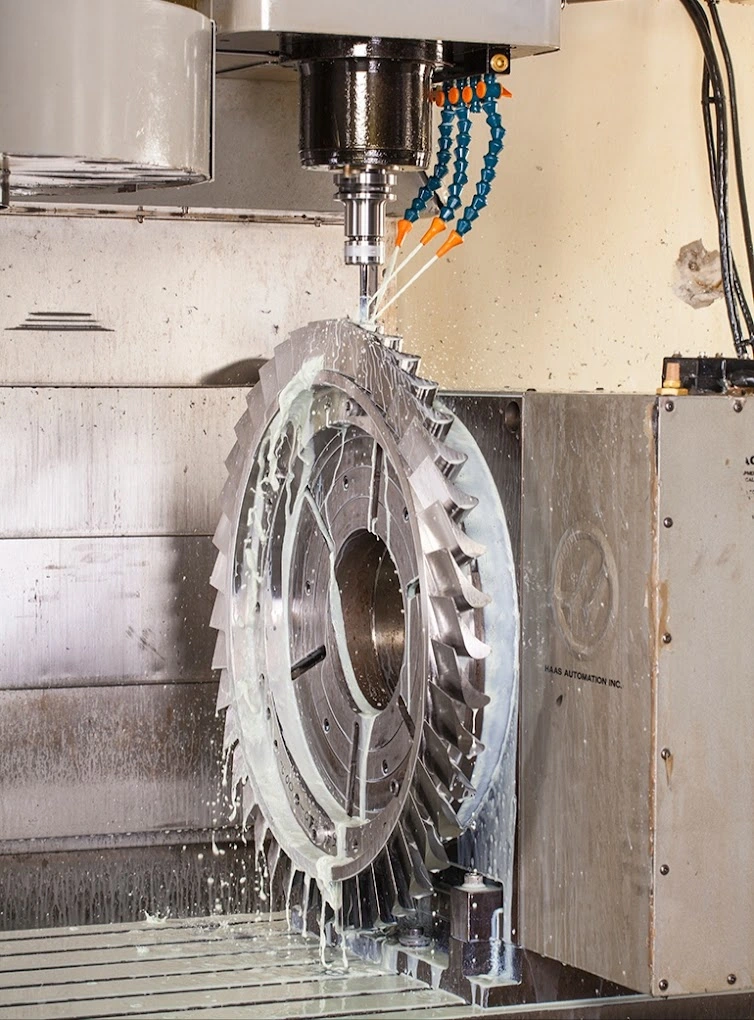
- 3D Printing and Additive Manufacturing: Additive manufacturing techniques, such as 3D printing, are being used to produce complex turbine components with high precision and reduced lead times. This technology enables the production of lightweight and intricate designs that enhance performance and reduce manufacturing costs.
- Cooling Technologies: Advanced cooling technologies, such as steam-cooled and air-cooled designs, have been developed to manage heat and improve efficiency. These cooling systems optimize temperature distribution and reduce the risk of overheating, enhancing turbine reliability.
Digitalization and Control Systems
Digitalization and advanced control systems are transforming the operation and maintenance of steam turbines, offering new opportunities for optimization and efficiency. Key developments in this area include:
- Digital Twins: Digital twin technology involves creating a virtual replica of a physical turbine, allowing for real-time monitoring, simulation, and analysis. Digital twins enable predictive maintenance, performance optimization, and troubleshooting, reducing downtime and operational costs.
- Advanced Monitoring and Diagnostics: Modern steam turbines are equipped with advanced sensors and monitoring systems that provide real-time data on key parameters such as temperature, pressure, and vibration. These systems enable early detection of issues and facilitate proactive maintenance and decision-making.
- Automated Control Systems: Automated control systems, powered by artificial intelligence and machine learning algorithms, optimize turbine operation by adjusting parameters in response to changing conditions. These systems enhance efficiency, reduce emissions, and improve overall performance.
- Remote Monitoring and Control: Remote monitoring and control capabilities allow operators to oversee turbine performance from centralized locations, enabling quick responses to issues and enhancing operational efficiency. This technology is particularly valuable for managing large fleets of turbines across multiple sites.
Future Trends in Steam Turbine Technology
The future of steam turbine technology is shaped by ongoing research and development efforts aimed at improving efficiency, sustainability, and integration with emerging energy systems. Key trends include:
- Integration with Renewable Energy: Steam turbines are increasingly being integrated with renewable energy systems, such as solar thermal and geothermal, to enhance efficiency and provide reliable base-load power. Hybrid systems that combine renewable sources with steam turbines are expected to play a significant role in the future energy landscape.
- Decarbonization and Emissions Reduction: Efforts to reduce carbon emissions and environmental impact are driving innovations in steam turbine technology. Carbon capture and storage (CCS) systems, advanced combustion technologies, and improved efficiency are key areas of focus in reducing the carbon footprint of steam turbines.
- Energy Storage and Grid Integration: The integration of steam turbines with energy storage systems, such as batteries and thermal storage, is being explored to enhance grid stability and support the integration of intermittent renewable sources. These systems enable flexible and reliable power generation, contributing to a more resilient energy grid.
- Micro and Small-Scale Turbines: The development of micro and small-scale steam turbines is gaining attention for decentralized power generation and off-grid applications. These turbines offer the potential for localized energy solutions and enhanced energy security, particularly in remote and underserved areas.
Maintenance and Operational Challenges
The operation and maintenance of steam turbines present various challenges that must be addressed to ensure optimal performance, reliability, and longevity. This section will explore common maintenance and operational challenges associated with steam turbines, highlighting best practices and strategies for overcoming these issues.
Common Issues and Solutions
Steam turbines are complex machines subject to a range of operational challenges that can impact performance and efficiency. Common issues include:
- Corrosion and Erosion: Corrosion and erosion are significant challenges in steam turbines, particularly in components exposed to high temperatures and aggressive environments. These issues can lead to reduced efficiency, increased maintenance costs, and shortened component lifespans. Solutions include using corrosion-resistant materials, implementing protective coatings, and optimizing steam chemistry to minimize corrosive agents.
- Fouling and Deposits: Fouling and deposits can accumulate on turbine components, reducing heat transfer efficiency and impairing performance. Regular cleaning and maintenance, as well as the use of advanced filtration and water treatment systems, can help mitigate fouling and deposits.
- Vibration and Noise: Vibration and noise can affect the performance and lifespan of steam turbines, potentially leading to mechanical failures and operational disruptions. Engineers use techniques such as balancing, damping, and vibration analysis to identify and address the sources of vibration and noise.
- Thermal Stress and Fatigue: Steam turbines are subjected to thermal stress and fatigue due to cyclic loading and temperature fluctuations. These conditions can lead to cracking, deformation, and other structural issues. Engineers use advanced materials, design optimization, and thermal management strategies to mitigate thermal stress and fatigue.
- Seal and Gasket Failures: Seals and gaskets are critical components that prevent leaks and maintain pressure differentials within the turbine. Failures can lead to reduced efficiency and increased maintenance requirements. Proper selection, installation, and maintenance of seals and gaskets are essential to ensure reliable operation.
Importance of Regular Maintenance
Regular maintenance is crucial to the reliable and efficient operation of steam turbines. Key maintenance practices include:
- Scheduled Inspections: Regular inspections are essential to identify potential issues and ensure that turbine components are in good condition. Inspections may involve visual examinations, non-destructive testing, and performance evaluations.
- Predictive Maintenance: Predictive maintenance techniques, such as vibration analysis and thermal imaging, are used to monitor turbine performance and identify potential issues before they become critical. This proactive approach minimizes downtime and reduces maintenance costs.
- Lubrication Management: Proper lubrication is essential to minimize friction and wear in turbine components. Regular monitoring and maintenance of lubrication systems ensure optimal performance and extend component lifespans.
- Cleaning and Servicing: Cleaning and servicing of turbine components are necessary to remove fouling, deposits, and other contaminants that can impair performance. Regular cleaning improves heat transfer efficiency and reduces the risk of mechanical failures.
- Calibration and Adjustment: Calibration and adjustment of control systems, sensors, and actuators are necessary to maintain accurate and reliable operation. Regular calibration ensures that turbines operate within safe and efficient parameters.
Case Studies of Failure and Recovery
Case studies of steam turbine failures and recoveries provide valuable insights into best practices and strategies for overcoming operational challenges. Examples include:
- Turbine Blade Failure: A power plant experienced a sudden loss of power due to a turbine blade failure caused by fatigue cracking. An investigation revealed that inadequate maintenance and inspection had contributed to the failure. The plant implemented a comprehensive maintenance program, including regular inspections and predictive maintenance techniques, to prevent future issues.
- Corrosion-Induced Shutdown: A chemical processing facility faced a prolonged shutdown due to corrosion in the turbine’s steam path. The facility adopted advanced materials and coatings to enhance corrosion resistance and implemented a steam chemistry optimization program to reduce corrosive agents.
- Vibration-Related Performance Issues: A paper mill experienced reduced efficiency and increased maintenance costs due to excessive vibration in its steam turbines. Engineers conducted a detailed vibration analysis and implemented balancing and damping solutions to address the issue, resulting in improved performance and reliability.
Conclusion
Steam turbines remain a vital component of the global energy landscape, offering reliable and efficient power generation across various industries and applications. This article has provided a comprehensive overview of steam turbines, exploring their history, design, operation, and applications, as well as recent technological advancements and maintenance challenges.
Summary of Key Points
- Historical Evolution: Steam turbines have evolved significantly since their invention in the late 19th century, with advancements in design, materials, and technology driving improvements in efficiency and performance.
- Principles of Operation: Steam turbines operate based on the principles of thermodynamics, converting thermal energy from steam into mechanical work through the Rankine cycle. The efficiency and performance of steam turbines are influenced by factors such as steam pressure, temperature, and the effectiveness of the condensation process.
- Design and Components: The design of steam turbines involves the integration of various components, including rotors, blades, casings, and nozzles. Advances in materials and manufacturing techniques have enhanced turbine performance and reliability.
- Applications: Steam turbines are employed in a wide range of applications, including power generation, industrial processes, and combined heat and power (CHP) systems. Their versatility and efficiency make them a preferred choice for many industries.
- Advantages and Disadvantages: Steam turbines offer numerous advantages, such as high efficiency, reliability, and scalability, but they also have certain disadvantages, including complexity, cost, and environmental impact.
- Technological Advancements: Recent advancements in steam turbine technology, including innovations in design, materials, and digitalization, are shaping the future of the industry and enhancing efficiency and sustainability.
- Maintenance and Operational Challenges: The operation and maintenance of steam turbines present various challenges, including corrosion, fouling, vibration, and thermal stress. Regular maintenance and best practices are essential to ensure optimal performance and reliability.
Future Outlook for Steam Turbines
The future of steam turbines is shaped by ongoing research and development efforts aimed at improving efficiency, sustainability, and integration with emerging energy systems. As the energy landscape continues to evolve, steam turbines are expected to play a key role in supporting the transition to a more sustainable and resilient energy future. Key areas of focus include:
- Decarbonization: Efforts to reduce carbon emissions and environmental impact will drive innovations in steam turbine technology, including carbon capture and storage (CCS) systems and advanced combustion technologies.
- Integration with Renewables: The integration of steam turbines with renewable energy systems, such as solar thermal and geothermal, will enhance efficiency and provide reliable base-load power, contributing to a more sustainable energy mix.
- Digitalization and Automation: Advances in digitalization and automation will enable more efficient and reliable operation of steam turbines, reducing maintenance costs and enhancing performance.
- Energy Storage and Grid Integration: The integration of steam turbines with energy storage systems and advanced grid technologies will support the transition to a more flexible and resilient energy grid.
In conclusion, steam turbines continue to be a cornerstone of the global energy industry, offering reliable and efficient power generation solutions for a wide range of applications. As technology advances and the energy landscape evolves, steam turbines will remain an essential component of the energy mix, contributing to a more sustainable and resilient energy future.
New Materials in Steam Turbine Construction
The development of new materials for steam turbines is crucial for improving their efficiency, reliability, and durability. These advancements in materials science have enabled steam turbines to operate at higher temperatures and pressures, enhancing their overall performance and reducing maintenance requirements. This section explores the latest innovations in turbine materials, their benefits, and the challenges associated with their implementation.
High-Temperature Alloys
High-temperature alloys are essential for steam turbine components exposed to extreme conditions. These materials must withstand high temperatures, pressures, and corrosive environments while maintaining mechanical strength and resistance to degradation.
- Nickel-Based Superalloys: Nickel-based superalloys are widely used in steam turbine blades and rotors due to their exceptional high-temperature strength and resistance to creep, oxidation, and corrosion. These alloys can operate at temperatures exceeding 700°C (1292°F), allowing for more efficient energy conversion. Recent advancements have focused on optimizing the microstructure and composition of these alloys to further enhance their performance. Examples of nickel-based superalloys include Inconel 718, René 80, and Nimonic 263.
- Cobalt-Based Superalloys: Cobalt-based superalloys are known for their excellent thermal fatigue resistance and are used in components where thermal cycling is a concern. They also offer good corrosion resistance and are often used in environments with high sulfur content. Cobalt-based alloys such as Haynes 188 and FSX-414 are common in specific turbine applications.
- Titanium Alloys: Titanium alloys are valued for their high strength-to-weight ratio, making them suitable for low-pressure turbine blades and components where weight reduction is essential. Titanium alloys such as Ti-6Al-4V are used in applications where both corrosion resistance and mechanical strength are required. Advances in processing techniques, such as powder metallurgy, have improved the properties of titanium alloys, making them more competitive with traditional materials.
Ceramic and Composite Materials
Ceramic and composite materials are being explored for use in steam turbines due to their unique properties, such as high-temperature resistance, low density, and excellent thermal insulation. These materials offer potential benefits in terms of efficiency and environmental impact.
- Ceramic Matrix Composites (CMCs): CMCs are lightweight materials that can withstand extremely high temperatures, making them suitable for turbine blades and other hot-section components. They offer superior thermal stability, corrosion resistance, and reduced weight compared to traditional metal alloys. CMCs, such as silicon carbide (SiC) and alumina-based composites, are being used to improve the efficiency of steam turbines by allowing for higher operating temperatures.
- Silicon Carbide (SiC) Ceramics: SiC ceramics are known for their high thermal conductivity, low thermal expansion, and excellent wear resistance. They are used in turbine components such as nozzles and seals, where durability and thermal stability are critical. Advances in manufacturing techniques, such as chemical vapor infiltration, have enabled the production of complex SiC ceramic components with improved properties.
- Glass and Carbon Fiber Composites: Glass and carbon fiber composites are used in non-load-bearing components, such as casings and covers, to reduce weight and improve thermal insulation. These materials offer high strength-to-weight ratios and can be tailored to specific applications through variations in fiber orientation and resin matrices.
Coatings and Surface Treatments
Coatings and surface treatments play a vital role in enhancing the performance and lifespan of steam turbine components. They provide protection against corrosion, erosion, and thermal degradation, improving overall reliability and efficiency.
- Thermal Barrier Coatings (TBCs): TBCs are applied to turbine blades and vanes to insulate the underlying metal from high temperatures, allowing for higher operating temperatures and improved efficiency. These coatings typically consist of a ceramic layer, such as yttria-stabilized zirconia (YSZ), which provides thermal insulation, and a metallic bond coat that enhances adhesion and protects against oxidation. Recent developments in TBC technology have focused on increasing the thermal stability and durability of these coatings, enabling turbines to operate at even higher temperatures.
- Erosion and Corrosion-Resistant Coatings: Erosion and corrosion-resistant coatings protect turbine components from wear and chemical attack, extending their service life and reducing maintenance requirements. These coatings are typically applied using techniques such as thermal spraying, physical vapor deposition (PVD), or chemical vapor deposition (CVD). Advances in nanostructured coatings have improved their effectiveness, offering enhanced protection against aggressive environments.
- Oxidation-Resistant Coatings: Oxidation-resistant coatings are used to protect metal components from high-temperature oxidation, which can lead to material degradation and failure. These coatings are often composed of aluminide or platinum-aluminide layers, which form a protective oxide scale on the surface. Researchers are exploring new coating compositions and application methods to further improve oxidation resistance and extend component lifespans.
Challenges and Considerations
While new materials offer significant advantages for steam turbines, their implementation also presents several challenges and considerations:
- Cost and Availability: Advanced materials, such as superalloys and CMCs, can be expensive and may require specialized manufacturing processes. Balancing material performance with cost-effectiveness is a critical consideration in turbine design and production.
- Manufacturing and Fabrication: The fabrication of complex turbine components using new materials requires advanced manufacturing techniques, such as additive manufacturing and precision casting. Ensuring consistency and quality in material properties and component dimensions is essential for reliable turbine operation.
- Compatibility and Integration: Integrating new materials into existing turbine designs may require modifications to component geometries and assembly methods. Compatibility with other materials and systems, such as cooling and lubrication, must be carefully evaluated to avoid issues such as thermal expansion mismatch and galvanic corrosion.
- Testing and Validation: Extensive testing and validation are necessary to ensure that new materials meet the performance and reliability requirements of steam turbines. This includes evaluating material properties under simulated operating conditions, such as high temperatures, pressures, and cyclic loading.
Conclusion
The development of new materials for steam turbines is driving significant advancements in their performance, efficiency, and reliability. High-temperature alloys, ceramics, composites, and advanced coatings are enabling turbines to operate at higher temperatures and pressures, improving energy conversion efficiency and reducing environmental impact. As research and development continue, these materials will play a crucial role in shaping the future of steam turbine technology, contributing to a more sustainable and efficient energy landscape.
Improvements in Steam Turbine Lifespan
Improving the lifespan of steam turbines is a critical aspect of modern engineering, as it directly impacts the reliability, efficiency, and overall cost-effectiveness of power generation systems. Enhancements in materials, design, maintenance practices, and technological innovations have all contributed to extending the operational life of steam turbines. This section explores these improvements in detail, focusing on key factors that contribute to longer turbine lifespans.
Extending the lifespan of steam turbines is essential for optimizing the economic and operational performance of power generation systems. Advances in materials, design, maintenance practices, and technology have all contributed to enhancing the longevity and reliability of steam turbines. This section explores key strategies and innovations that improve turbine lifespan.
Advanced Materials and Coatings
The use of advanced materials and coatings plays a vital role in increasing the lifespan of steam turbines by enhancing their resistance to high temperatures, corrosion, erosion, and mechanical stresses.
- High-Temperature Alloys: The development of high-temperature alloys, such as nickel-based superalloys and titanium alloys, has significantly improved the durability of turbine components. These materials offer excellent mechanical strength, creep resistance, and corrosion resistance at elevated temperatures, allowing turbines to operate more efficiently and reliably over extended periods.
- Ceramic Matrix Composites (CMCs): CMCs are increasingly used in turbine blades and hot-section components due to their superior thermal stability and resistance to wear and corrosion. By reducing the thermal stresses experienced by metal components, CMCs help extend the life of critical turbine parts.
- Advanced Coatings: Protective coatings, such as thermal barrier coatings (TBCs), erosion-resistant coatings, and anti-corrosion coatings, are applied to turbine components to protect them from environmental damage and mechanical wear. These coatings reduce material degradation and extend component lifespans, leading to longer turbine operation and reduced maintenance costs.
Design Optimization
Innovations in turbine design have focused on reducing mechanical stresses, improving thermal efficiency, and enhancing the overall reliability of turbines, contributing to longer lifespans.
- Optimized Blade Design: Advances in computational fluid dynamics (CFD) and computer-aided design (CAD) have enabled engineers to optimize blade geometries for improved aerodynamic performance and reduced mechanical stresses. Optimized blades experience less fatigue and wear, resulting in extended service life.
- Cooling Technologies: Effective cooling systems, such as steam-cooled and air-cooled designs, help manage the heat load on turbine components, reducing thermal stress and extending the lifespan of critical parts. These cooling technologies ensure that components operate within safe temperature limits, preventing overheating and material degradation.
- Vibration Control: Vibration and resonance can lead to mechanical fatigue and failure in turbine components. Design strategies that minimize vibration, such as improved balancing and damping systems, contribute to the longevity and reliability of steam turbines.
- Stress-Relief Techniques: Design modifications that reduce stress concentrations, such as smooth transitions and rounded corners in component geometries, help prevent crack initiation and propagation. These stress-relief techniques improve the durability of turbine components and extend their operational life.
Enhanced Maintenance Practices
Regular maintenance and monitoring are critical to ensuring the long-term performance and reliability of steam turbines. Advances in maintenance practices have contributed to improved turbine lifespans.
- Predictive Maintenance: Predictive maintenance techniques, such as condition monitoring, vibration analysis, and thermal imaging, allow operators to detect potential issues before they become critical. By identifying signs of wear, corrosion, or mechanical stress early, predictive maintenance enables timely interventions and prevents costly failures.
- Regular Inspections and Servicing: Scheduled inspections and servicing ensure that turbine components are in good condition and operating within specified parameters. Routine maintenance tasks, such as cleaning, lubrication, and calibration, help maintain optimal performance and extend the life of turbine components.
- Component Refurbishment and Replacement: Refurbishment and replacement of worn or damaged components are essential to extending turbine lifespan. By renewing key parts, such as blades, rotors, and bearings, operators can restore turbine performance and prevent further degradation.
- Operator Training and Expertise: Well-trained operators and maintenance personnel are critical to the effective management of steam turbines. Comprehensive training programs and access to technical expertise ensure that turbines are operated and maintained correctly, reducing the risk of failures and extending lifespan.
Technological Innovations
Recent technological innovations have contributed to the improved lifespan of steam turbines by enhancing performance, efficiency, and reliability.
- Digital Twin Technology: Digital twins are virtual models of physical turbines that enable real-time monitoring, simulation, and analysis. By providing detailed insights into turbine performance and health, digital twins facilitate predictive maintenance and optimization strategies, extending turbine lifespan.
- Advanced Control Systems: Automated control systems, powered by artificial intelligence and machine learning algorithms, optimize turbine operation by adjusting parameters in response to changing conditions. These systems enhance efficiency, reduce emissions, and improve overall performance, contributing to longer turbine lifespans.
- Remote Monitoring and Diagnostics: Remote monitoring and diagnostics capabilities allow operators to oversee turbine performance from centralized locations, enabling quick responses to issues and enhancing operational efficiency. This technology is particularly valuable for managing large fleets of turbines across multiple sites.
- Energy Management Systems: Advanced energy management systems optimize the operation of steam turbines in conjunction with other power generation assets, such as gas turbines and renewable energy sources. By coordinating energy production and consumption, these systems improve overall efficiency and reduce wear on turbine components, extending their lifespan.
Case Studies and Success Stories
Examining real-world examples of turbine lifespan improvements can provide valuable insights into best practices and strategies for extending the life of steam turbines.
- Combined Cycle Power Plant Optimization: A combined cycle power plant implemented a comprehensive maintenance and optimization program, including predictive maintenance techniques, advanced coatings, and digital twin technology. As a result, the plant extended the lifespan of its steam turbines by 30%, reducing maintenance costs and improving overall efficiency.
- Geothermal Plant Erosion Mitigation: A geothermal power plant faced challenges with erosion and corrosion due to the presence of abrasive particles and corrosive impurities in the steam. By implementing erosion-resistant coatings and optimizing steam chemistry, the plant significantly extended the life of its turbine components, enhancing reliability and performance.
- Nuclear Power Plant Component Refurbishment: A nuclear power plant conducted a detailed analysis of its steam turbine components and identified key areas for refurbishment and replacement. By renewing critical parts and implementing advanced materials and coatings, the plant extended the lifespan of its turbines and improved safety and efficiency.
Conclusion
Enhancing the lifespan of steam turbines is a multifaceted challenge that requires advancements in materials, design, maintenance practices, and technology. By leveraging high-temperature alloys, ceramic composites, advanced coatings, and digital technologies, engineers can significantly extend the operational life of steam turbines, improving reliability, efficiency, and cost-effectiveness. As research and development continue, further innovations in turbine materials and technology will play a crucial role in achieving a more sustainable and efficient energy future.
Turbine Efficiency Gains
Improving the efficiency of steam turbines is a major focus in power generation, as even small gains can lead to significant reductions in fuel consumption and greenhouse gas emissions. Over the years, advancements in materials, design, and technology have contributed to notable improvements in steam turbine efficiency. This section explores the various factors and innovations that have driven efficiency gains in steam turbines.
The efficiency of steam turbines is crucial for optimizing power generation and reducing environmental impact. Advances in design, materials, technology, and operational practices have all contributed to significant efficiency gains in steam turbines. This section examines the key factors and innovations driving these improvements.
Thermodynamic Principles and Efficiency
The efficiency of steam turbines is governed by thermodynamic principles, primarily focusing on the conversion of thermal energy into mechanical work. The Rankine cycle, which is the basis for steam turbine operation, involves several stages: heat addition, expansion, heat rejection, and compression. The efficiency of a steam turbine can be enhanced by optimizing these stages.
- Higher Steam Temperatures and Pressures: One of the most effective ways to increase turbine efficiency is to operate at higher steam temperatures and pressures. By increasing the thermal energy available for conversion, higher steam conditions enable greater energy extraction. Modern supercritical and ultra-supercritical turbines operate at pressures above the critical point of water (22.1 MPa) and temperatures above 600°C, achieving efficiencies of over 45%.
- Reheat and Regenerative Cycles: The use of reheat and regenerative cycles can improve turbine efficiency by minimizing energy losses. In a reheat cycle, steam is partially expanded in the turbine, reheated in a boiler, and then expanded further in another turbine stage. This process increases the average temperature at which heat is added, improving efficiency. Regenerative cycles use feedwater heaters to preheat the water entering the boiler, recovering waste heat and reducing fuel consumption.
- Advanced Thermodynamic Cycles: Innovations in thermodynamic cycles, such as the combined cycle and organic Rankine cycle (ORC), have also contributed to efficiency gains. Combined cycle power plants integrate gas turbines with steam turbines, using waste heat from the gas turbine to generate steam and improve overall efficiency. ORC systems utilize organic fluids with lower boiling points than water, enabling efficient energy conversion from low-temperature heat sources.
Advanced Materials and Blade Design
The development of advanced materials and optimized blade designs has played a significant role in enhancing steam turbine efficiency.
- High-Temperature Materials: The use of high-temperature materials, such as nickel-based superalloys and ceramic matrix composites (CMCs), allows turbines to operate at higher temperatures and pressures, improving thermal efficiency. These materials offer excellent strength, corrosion resistance, and thermal stability, enabling more efficient energy conversion.
- Aerodynamic Blade Design: Advances in computational fluid dynamics (CFD) and computer-aided design (CAD) have enabled the optimization of blade geometries for improved aerodynamic performance. Modern turbine blades are designed to minimize aerodynamic losses and maximize energy extraction, reducing turbulence and increasing efficiency. Techniques such as 3D blading and contoured endwalls further enhance aerodynamic performance.
- Tip Clearance Control: Minimizing tip clearance between turbine blades and the casing reduces aerodynamic losses and improves efficiency. Advanced tip clearance control systems, such as active clearance control and abradable coatings, help maintain optimal clearances and reduce leakage losses.
- Blade Coatings and Surface Treatments: The application of advanced coatings and surface treatments to turbine blades enhances their resistance to erosion, corrosion, and thermal degradation, improving efficiency and extending lifespan. Thermal barrier coatings (TBCs) and erosion-resistant coatings help maintain blade integrity and performance.
Digitalization and Control Systems
Digitalization and advanced control systems have transformed the operation and efficiency of steam turbines.
- Real-Time Monitoring and Diagnostics: Advanced sensors and monitoring systems provide real-time data on key turbine parameters, such as temperature, pressure, and vibration. This data enables operators to optimize turbine performance and efficiency, detect potential issues early, and implement corrective actions.
- Automated Control Systems: Automated control systems, powered by artificial intelligence and machine learning algorithms, optimize turbine operation by adjusting parameters in response to changing conditions. These systems enhance efficiency, reduce emissions, and improve overall performance.
- Digital Twins: Digital twin technology creates virtual models of physical turbines, allowing for real-time simulation and analysis. Digital twins enable predictive maintenance and optimization strategies, improving efficiency and reliability.
- Predictive Maintenance: Predictive maintenance techniques, such as condition monitoring and vibration analysis, help identify potential issues before they become critical. By enabling timely interventions and optimizing maintenance schedules, predictive maintenance contributes to improved turbine efficiency and reduced downtime.
Operational Strategies and Best Practices
Operational strategies and best practices play a crucial role in maximizing steam turbine efficiency.
- Load Optimization: Operating turbines at optimal load levels ensures maximum efficiency and minimizes energy losses. Advanced control systems and real-time monitoring enable operators to adjust turbine output based on demand, optimizing efficiency.
- Startup and Shutdown Procedures: Efficient startup and shutdown procedures minimize energy losses and thermal stress, reducing wear on turbine components and improving efficiency. Advanced control systems automate these procedures, ensuring consistent and optimal performance.
- Fuel Quality and Steam Purity: Maintaining high fuel quality and steam purity is essential for efficient turbine operation. Impurities in fuel and steam can cause fouling, corrosion, and erosion, reducing efficiency and increasing maintenance requirements. Regular monitoring and treatment of fuel and steam ensure optimal performance.
- Waste Heat Recovery: Implementing waste heat recovery systems, such as heat exchangers and economizers, recovers energy from exhaust gases and other heat sources, improving overall plant efficiency. Combined cycle power plants and cogeneration systems are examples of effective waste heat recovery.
Case Studies and Success Stories
Real-world examples of efficiency improvements provide valuable insights into best practices and strategies for enhancing steam turbine efficiency.
- Ultra-Supercritical Power Plant Efficiency Gains: An ultra-supercritical power plant implemented advanced materials, optimized blade designs, and digital control systems to achieve efficiencies of over 47%. By operating at high temperatures and pressures, the plant reduced fuel consumption and emissions while maximizing energy output.
- Combined Cycle Plant Optimization: A combined cycle power plant integrated advanced monitoring and control systems, along with waste heat recovery techniques, to improve efficiency. The plant achieved overall efficiencies of over 60%, demonstrating the potential of combined cycle technology for efficient power generation.
- Geothermal Plant Efficiency Enhancement: A geothermal power plant implemented organic Rankine cycle (ORC) technology and advanced blade coatings to improve efficiency. By utilizing low-temperature heat sources and minimizing energy losses, the plant increased energy output and reduced operational costs.
Conclusion
Enhancing the efficiency of steam turbines is a multifaceted challenge that requires advancements in materials, design, technology, and operational practices. By leveraging high-temperature materials, optimized blade designs, digitalization, and advanced control systems, engineers have achieved significant efficiency gains in steam turbines, reducing fuel consumption and environmental impact. As research and development continue, further innovations in turbine technology will play a crucial role in achieving a more sustainable and efficient energy future.
Components of a Steam Turbine and Their Manufacturing
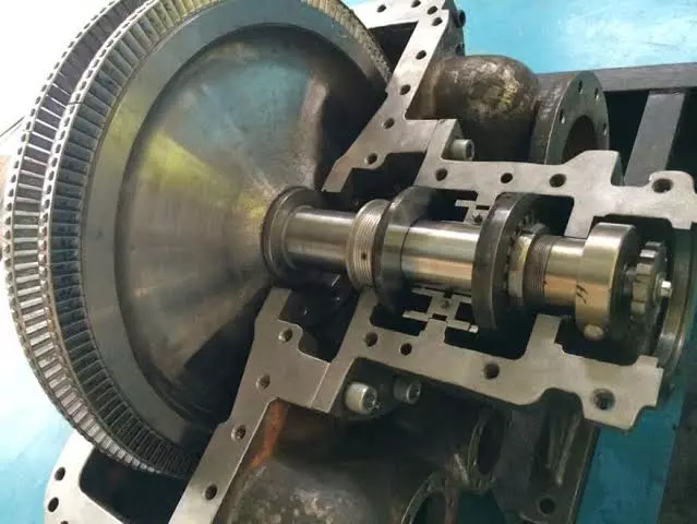
Steam turbines are complex machines comprised of various components, each playing a crucial role in the conversion of steam energy into mechanical work. Understanding the components and their manufacturing processes provides insights into the engineering and technology involved in steam turbine construction.
1. Rotor
Description
The rotor is the central shaft of the steam turbine to which the turbine blades are attached. It is a critical component that converts steam energy into mechanical energy and transmits the rotational motion to the generator or mechanical load.
Manufacturing Process
- Material Selection: Rotors are typically made from high-strength, low-alloy steels, such as chromium-molybdenum-vanadium (CrMoV) alloys, which offer excellent mechanical properties and resistance to thermal stresses.
- Forging: The rotor is usually manufactured through a hot forging process, where a large billet of steel is heated to high temperatures and shaped into a rough form using a hydraulic press or hammer. This process aligns the grain structure and enhances the strength and toughness of the material.
- Machining: After forging, the rotor undergoes precision machining to achieve the desired dimensions and surface finish. Computer numerical control (CNC) machines are used to mill, turn, and grind the rotor to exact specifications. Machining operations ensure tight tolerances and balance, which are crucial for minimizing vibration and maximizing efficiency.
- Heat Treatment: The rotor is subjected to heat treatment processes, such as quenching and tempering, to enhance its mechanical properties. Heat treatment improves the rotor’s strength, toughness, and resistance to creep and fatigue.
- Balancing: Dynamic balancing is performed to ensure that the rotor operates smoothly at high speeds without causing excessive vibration. Balancing involves adding or removing material from the rotor to achieve even weight distribution.
- Inspection and Testing: The rotor undergoes rigorous inspection and testing, including non-destructive testing (NDT) techniques such as ultrasonic testing and magnetic particle inspection, to detect any defects or inconsistencies.
2. Blades
Description
Turbine blades are airfoil-shaped components that extract energy from the steam and convert it into rotational motion. They are critical for the efficiency and performance of the steam turbine.
Manufacturing Process
- Material Selection: Blades are typically made from high-performance materials such as nickel-based superalloys or titanium alloys. These materials offer excellent resistance to high temperatures, corrosion, and mechanical stresses.
- Precision Casting: Investment casting, also known as lost-wax casting, is commonly used to manufacture turbine blades. This process involves creating a wax model of the blade, coating it with ceramic material to form a mold, and then melting away the wax. Molten metal is poured into the mold to form the blade.
- Directional Solidification: Advanced casting techniques, such as directional solidification and single-crystal growth, are used to enhance the mechanical properties of turbine blades. These techniques control the grain structure of the material, improving resistance to creep and fatigue.
- Machining and Finishing: After casting, blades undergo precision machining and finishing processes to achieve the desired shape and surface quality. CNC machines are used to mill and grind the blades to exact specifications.
- Coating Application: Blades are coated with protective coatings, such as thermal barrier coatings (TBCs) and erosion-resistant coatings, to enhance their durability and performance. Coatings are applied using techniques such as thermal spraying or chemical vapor deposition (CVD).
- Inspection and Testing: Blades undergo rigorous inspection and testing, including non-destructive testing methods, to ensure they meet quality and performance standards. High-resolution imaging and ultrasonic testing are commonly used to detect defects.
3. Casing
Description
The casing, or housing, encloses the steam turbine and provides structural support. It directs the flow of steam through the turbine stages and helps maintain pressure and temperature conditions.
Manufacturing Process
- Material Selection: Casings are typically made from cast steel or ductile iron, offering a good balance of strength, toughness, and thermal resistance.
- Casting: The casing is usually manufactured through sand casting, where a pattern of the casing is made from wood or metal, and sand is packed around it to form a mold. Molten metal is poured into the mold to create the casing.
- Machining: After casting, the casing undergoes machining to achieve the required dimensions and tolerances. CNC machines are used to machine flanges, openings, and mounting surfaces.
- Heat Treatment: Heat treatment processes, such as annealing, are used to relieve internal stresses and improve the mechanical properties of the casing.
- Assembly and Welding: Large casings may consist of multiple sections that are assembled and welded together. Welds are inspected using non-destructive testing methods to ensure quality and integrity.
- Inspection and Testing: Casings undergo inspection and testing, including pressure testing and dimensional checks, to ensure they meet performance and safety standards.
4. Bearings
Description
Bearings support the rotor and allow it to rotate smoothly with minimal friction. They are critical for maintaining the alignment and stability of the turbine shaft.
Manufacturing Process
- Material Selection: Bearings are typically made from materials such as high-strength steel, babbitt (a soft metal alloy), or ceramics. Material selection depends on the specific application and operating conditions.
- Precision Machining: Bearings are manufactured using precision machining techniques to achieve tight tolerances and smooth surfaces. CNC machines are used to machine the bearing races and rolling elements.
- Heat Treatment: Heat treatment processes, such as case hardening, are used to enhance the wear resistance and fatigue strength of bearing components.
- Assembly and Inspection: Bearings are assembled with rolling elements, such as balls or rollers, and subjected to inspection and testing to ensure proper fit and function.
- Lubrication System Integration: Bearings are integrated with lubrication systems to reduce friction and wear. Lubrication systems are designed to deliver a consistent supply of lubricant to the bearing surfaces.
5. Governor
Description
The governor is a control mechanism that regulates the speed and output of the steam turbine by adjusting the steam flow. It ensures that the turbine operates within safe and efficient parameters.
Manufacturing Process
- Component Fabrication: The governor consists of various components, such as valves, linkages, and actuators, which are manufactured using precision machining and fabrication techniques.
- Assembly: The components are assembled to create the governor mechanism, which is designed to respond to changes in turbine speed and load.
- Calibration and Testing: The governor is calibrated to ensure accurate and reliable control of the turbine speed and output. Testing involves simulating operating conditions to verify the governor’s performance.
- Integration with Control Systems: The governor is integrated with the turbine’s control systems, which may include digital controllers and sensors, to optimize performance and efficiency.
6. Nozzles
Description
Nozzles are used in impulse turbines to direct high-velocity steam jets onto the turbine blades, imparting momentum and causing rotation.
Manufacturing Process
- Material Selection: Nozzles are typically made from high-strength alloys that can withstand high temperatures and pressures, such as stainless steel or nickel-based superalloys.
- Precision Machining: Nozzles are manufactured using precision machining techniques to achieve the desired shape and flow characteristics. CNC machines are used to drill, mill, and shape the nozzle passages.
- Heat Treatment: Heat treatment processes, such as annealing or quenching, are used to enhance the mechanical properties of the nozzles.
- Coating Application: Nozzles may be coated with protective coatings to enhance their resistance to erosion and corrosion.
- Inspection and Testing: Nozzles undergo inspection and testing, including flow testing and dimensional checks, to ensure they meet performance standards.
7. Seals and Gaskets
Description
Seals and gaskets prevent steam leaks and maintain pressure differentials within the turbine. They are critical for efficient operation and preventing losses.
Manufacturing Process
- Material Selection: Seals and gaskets are made from materials that offer good sealing properties and resistance to high temperatures and pressures. Common materials include elastomers, graphite, and metal alloys.
- Molding and Cutting: Seals and gaskets are manufactured using molding or cutting processes, depending on the material and design. Rubber and elastomeric seals are typically molded, while metal gaskets are cut from sheets.
- Coating and Treatment: Seals and gaskets may undergo surface treatments, such as coatings or impregnations, to enhance their sealing properties and durability.
- Inspection and Testing: Seals and gaskets are inspected and tested for dimensional accuracy and sealing performance to ensure they meet quality standards.
Conclusion
The manufacturing of steam turbine components involves advanced materials, precision engineering, and rigorous quality control to ensure optimal performance, efficiency, and reliability. Each component plays a critical role in the overall operation of the turbine, and advancements in materials and manufacturing processes continue to drive improvements in turbine technology. As research and development progress, further innovations in turbine component manufacturing will contribute to a more sustainable and efficient energy future.
Steam Generation for a Steam Turbine
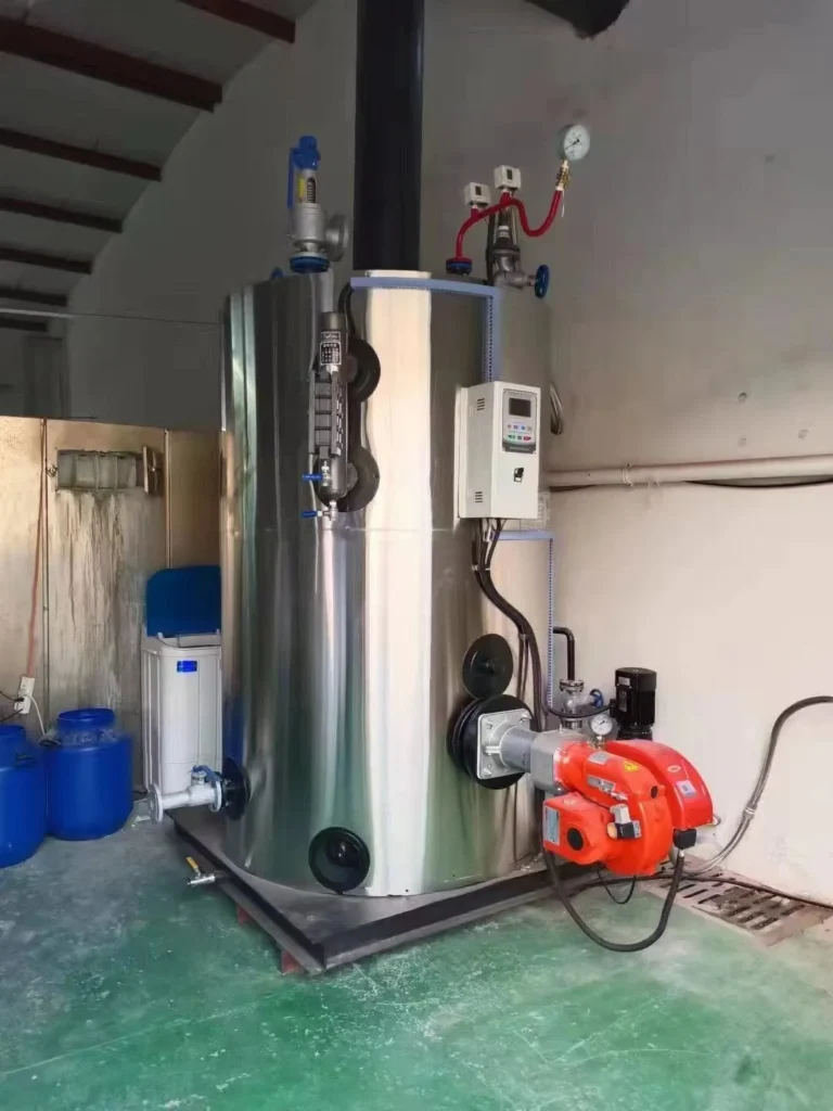
Steam generation is the process of producing steam from water. This steam can be used for various purposes, including power generation, heating, and industrial processes. The most common method of steam generation involves the use of a boiler, where water is heated to produce steam. Here is an overview of the steam generation process:
- Boiler: A boiler is a device that is designed to convert water into steam by applying heat energy to the water. The heat is usually generated by burning fuel, such as coal, natural gas, oil, or biomass, or by using electricity or renewable energy sources like solar or geothermal.
- Combustion or Heat Source: In fossil fuel-fired boilers, combustion occurs in a combustion chamber where the fuel is burned, releasing heat. The heat generated is transferred to the water in the boiler to raise its temperature.
- Water Feed: Water is fed into the boiler through a feedwater system. This can be a continuous process to maintain a steady supply of water to the boiler.
- Heat Transfer: The heat from the combustion process is transferred to the water in the boiler. This causes the water to reach a temperature at which it turns into steam.
- Steam Formation: As the water absorbs heat, it undergoes a phase change from liquid to vapor. The steam produced is then collected in the upper part of the boiler.
- Superheating (optional): In some cases, the steam is further heated to increase its temperature and energy content. This process is known as superheating and is done in a separate section of the boiler.
- Steam Distribution: Once the steam is generated, it can be distributed through pipelines for various applications. In power plants, the steam is often used to turn turbines connected to generators to produce electricity. In industrial processes, steam is utilized for heating, drying, and other manufacturing operations.
Boiler
A boiler is a closed vessel or apparatus designed to heat water or other fluids. It is an essential component in various industries, as it plays a key role in generating steam for power generation, heating systems, and industrial processes. The basic function of a boiler is to convert water into steam by applying heat energy to the water. Here are the key components and types of boilers:
Key Components of a Boiler:
- Burner: The burner is responsible for supplying the heat energy by burning fuel. Common fuels include natural gas, oil, coal, and biomass. The burner releases the heat into the combustion chamber.
- Combustion Chamber/Furnace: This is where the fuel is burned to release heat. The combustion chamber is designed to contain and control the combustion process.
- Heat Exchanger: The heat exchanger is a component that transfers heat from the combustion gases to the water, causing the water to convert into steam. Heat exchangers can be of various types, including fire-tube, water-tube, and coil-type designs.
- Water or Steam Drum: The drum serves as a reservoir for the water or steam. In water-tube boilers, multiple drums may be used to separate different stages of the steam generation process.
- Tubes or Coils: These are the pathways through which the hot gases or combustion products flow, transferring heat to the water. In fire-tube boilers, the tubes contain the water, while in water-tube boilers, the water flows through the tubes.
- Boiler Shell: The boiler shell is the outer cylindrical part that contains the pressure vessel and other components. It provides structural support and protection.
- Controls and Instrumentation: Boilers are equipped with various controls and instrumentation to monitor and regulate the combustion process, water level, pressure, and other parameters.
Types of Boilers:
- Fire-Tube Boilers: In these boilers, hot gases pass through tubes that are surrounded by water. The heat is transferred from the tubes to the water, producing steam. Fire-tube boilers are typically used for low to medium pressure applications.
- Water-Tube Boilers: In water-tube boilers, water flows through tubes, and combustion gases pass around these tubes. Water-tube boilers are often used in high-pressure applications and large industrial settings.
- Electric Boilers: These boilers use electricity to generate heat and are suitable for applications where other fuel sources may be impractical.
- Biomass Boilers: These boilers use organic materials, such as wood or agricultural residues, as fuel.
- Circulating Fluidized Bed (CFB) Boilers: CFB boilers use a fluidized bed of particles to efficiently burn solid fuels.
The choice of boiler type depends on factors such as the application, required steam pressure, and fuel availability. Boilers are critical components in providing heat and steam for a wide range of industrial and commercial processes, contributing significantly to energy production and various manufacturing operations.
Combustion or Heat Source
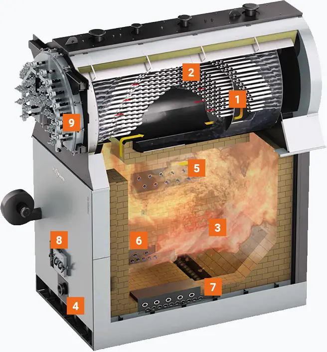
- 3-Pass boiler (6 bar – higher pressure ratings on request)
- Safety heat exchanger (integrated into boiler)
- Combustion chamber
- Blow-in ports
- Injection of secondary air
- Injection of flue gas recirculation
- Automatic ash removal from the combustion chamber using a water-cooled screw
- Firebox door
- Pneumatic boiler tube dedusting (optional)
The combustion or heat source in a boiler is a critical component responsible for generating the thermal energy needed to convert water into steam. The combustion process involves burning a fuel to release heat, and the choice of fuel depends on factors such as availability, cost, and environmental considerations. Common fuels used in boilers include:
- Natural Gas: A clean-burning fossil fuel that is widely used for heating and power generation. It produces fewer emissions compared to other fossil fuels.
- Oil (Diesel or Heavy Fuel Oil): Liquid fuels that are commonly used in boilers, especially in areas where natural gas availability is limited.
- Coal: A traditional and widely used fuel in boilers, especially in power plants. However, coal combustion releases higher levels of carbon dioxide and other pollutants compared to some other fuels.
- Biomass: Organic materials such as wood, crop residues, and animal waste can be used as biomass fuel in boilers. Biomass is considered renewable and can contribute to reduced greenhouse gas emissions.
- Electricity: Some boilers are electrically powered, using electricity as the heat source. This method is often used in areas where other fuel sources are impractical or expensive.
- Renewable Energy Sources: In some cases, boilers can be designed to use renewable energy sources like solar or geothermal energy to generate heat.
The combustion process typically takes place in a combustion chamber or furnace within the boiler. The key steps in combustion include:
- Fuel Combustion: The fuel is introduced into the combustion chamber, where it reacts with oxygen from the air. This chemical reaction releases heat energy.
- Flame Formation: The heat generated from the combustion reaction results in the formation of a flame. The flame is responsible for heating the surfaces of the boiler, including the heat exchanger or tubes.
- Transfer of Heat: The heat from the combustion process is transferred to the water or other fluid in the boiler. This transfer of heat causes the water to reach its boiling point, leading to the production of steam.
- Control of Combustion: To ensure efficient and safe operation, combustion in boilers is carefully controlled. This involves monitoring factors such as fuel-air ratio, temperature, and pressure to optimize combustion efficiency and minimize emissions.
Efficient combustion is crucial for the overall performance of a boiler system. Modern boilers often incorporate advanced control systems to regulate the combustion process, ensuring optimal efficiency, minimal environmental impact, and safe operation.
Water Feed
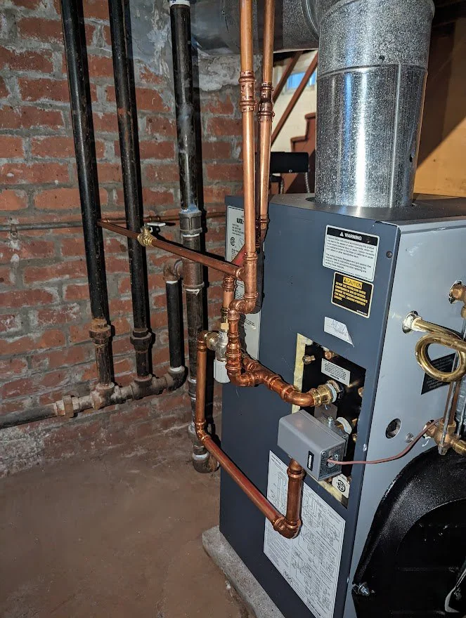
The water feed system in a boiler is a crucial component that manages the supply of water to the boiler for steam generation. This system ensures a continuous and controlled supply of water to the boiler, maintaining the desired water level. Proper water feed is essential for efficient and safe boiler operation. Here’s how the water feed system typically works:
- Water Source: The water feed system starts with a source of water, which can come from various places depending on the application. It might be from a city water supply, a well, or another water source.
- Make-up Water: In many boiler systems, a portion of the water is continuously removed from the system as steam is generated, and this water needs to be replaced. The replacement water is often referred to as make-up water.
- Feedwater Pump: The water feed system includes a pump, known as the feedwater pump, which is responsible for delivering the make-up water to the boiler. The pump ensures a consistent flow of water into the boiler.
- Feedwater Control Valve: A control valve is often installed to regulate the flow of water into the boiler. This valve is typically controlled by a level sensor or controller that monitors the water level inside the boiler. The valve opens or closes to adjust the flow of water and maintain the desired water level.
- Preheating (Optional): In some boiler systems, make-up water may be preheated before entering the boiler. Preheating the water can improve energy efficiency by utilizing waste heat from the flue gases or other sources.
- Water Treatment: Depending on the quality of the water source, water treatment processes may be employed to remove impurities and prevent scale or corrosion inside the boiler. This is important for the longevity and efficient operation of the boiler.
- Expansion Tank (Optional): In closed-loop systems, an expansion tank may be used to accommodate changes in water volume due to temperature variations. This helps maintain a stable pressure in the system.
The water feed system is designed to maintain the proper water level inside the boiler. If the water level is too low, it can expose the boiler tubes or heating surfaces to excessive heat, leading to potential damage. On the other hand, if the water level is too high, it can result in carryover of water into the steam, which can cause operational issues and reduce the efficiency of the system.
Proper water feed control is essential for the safe and efficient operation of boilers, and it is often automated using control systems to ensure precise and continuous regulation of water flow. Regular maintenance and monitoring of the water feed system are important aspects of boiler management.
Heat Transfer
Heat transfer is the process by which thermal energy is exchanged between different regions of a system or between different systems. There are three primary methods of heat transfer: conduction, convection, and radiation.
- Conduction:
- Definition: Conduction is the transfer of heat through a material without any movement of the material itself. It occurs when neighboring atoms or molecules transfer kinetic energy to each other.
- Example: When one end of a metal rod is heated, the heat energy is conducted through the material, and the other end of the rod becomes warm.
- Convection:
- Definition: Convection involves the transfer of heat through the movement of fluids (liquids or gases). It occurs due to the circulation of the fluid caused by temperature differences.
- Example: Heating water in a pot on a stove causes hot water to rise, creating a circulation pattern. As the hot water rises, cooler water moves down to replace it, resulting in a continuous flow of heat.
- Radiation:
- Definition: Radiation is the transfer of heat through electromagnetic waves, such as infrared radiation. Unlike conduction and convection, radiation does not require a medium and can occur in a vacuum.
- Example: The heat from the Sun reaches the Earth through radiation. Similarly, a heated electric coil radiates heat in an electric stove.
The effectiveness of each heat transfer method depends on the specific conditions and materials involved. In many real-world situations, multiple methods may occur simultaneously.
Applications:
- Cooking: Heat transfer is crucial in cooking processes. For example, conduction occurs when a pan is heated on a stove, convection occurs in the boiling of water, and radiation is involved in grilling or roasting.
- Engineering: Heat transfer is fundamental in various engineering applications, such as designing efficient heat exchangers, cooling systems for electronics, and insulation materials.
- Climate Control: HVAC systems use heat transfer principles to cool or heat buildings. For instance, air conditioning systems use a combination of conduction, convection, and sometimes radiation to remove heat from indoor spaces.
- Power Generation: In power plants, heat transfer is integral to the conversion of thermal energy into mechanical energy and then into electricity. Steam turbines, for example, rely on heat transfer to generate power.
Understanding and controlling heat transfer processes are essential for designing efficient systems, improving energy efficiency, and preventing undesired effects such as overheating or heat loss.
Steam Formation
Steam formation is a phase-change process in which water is converted from its liquid state to a gaseous state, which we commonly refer to as steam. This process occurs when water absorbs enough heat energy to overcome the latent heat of vaporization. Here’s a general overview of steam formation:
- Application of Heat:
- Steam formation begins with the application of heat to water. The heat can come from various sources, such as burning fossil fuels, nuclear reactions, or renewable energy sources like solar or geothermal.
- Temperature Increase:
- As heat is applied, the temperature of the water rises. At normal atmospheric pressure, water boils at 100 degrees Celsius (212 degrees Fahrenheit). However, the boiling point increases with pressure.
- Boiling:
- Once the water temperature reaches its boiling point at a given pressure, further application of heat does not cause a temperature increase. Instead, the absorbed heat is used to convert the water into steam.
- Phase Change:
- The phase change from liquid to gas involves the absorption of latent heat of vaporization. This is the energy required to break the bonds between water molecules and convert them from a liquid to a gaseous state without a change in temperature.
- Steam Generation:
- The resulting vapor is steam, which is composed of water vapor molecules. Steam is characterized by high energy content and the ability to do work, making it a valuable resource for various applications.
- Expansion (Optional):
- In some systems, steam can be further expanded or superheated, meaning its temperature is increased beyond the boiling point. This can enhance its energy content and specific properties.
The process of steam formation is a critical aspect of power generation in steam turbines. In power plants, water is heated in a boiler, and the resulting steam is directed onto turbine blades. The expansion of steam in the turbine generates mechanical energy, which is then used to turn generators and produce electricity.
It’s important to note that the conditions under which steam formation occurs, such as pressure and temperature, can influence the properties of the steam and its applications. Additionally, proper control and maintenance of steam generation systems are essential for efficient and safe operation.
Superheating
Superheating is a process in which steam is heated beyond its saturation point, which is the temperature at which it would normally boil at a given pressure. In other words, superheated steam is steam that has been further heated after reaching the boiling point and being completely vaporized.
The key characteristics of superheated steam include:
- Temperature Increase: Superheated steam is at a higher temperature than the saturation temperature corresponding to its pressure. The temperature of superheated steam is often measured in degrees Celsius or Fahrenheit.
- No Saturation: Unlike saturated steam, which is at the boiling point for a given pressure and contains both liquid and vapor phases, superheated steam consists entirely of vapor.
- Increased Energy Content: Superheated steam carries more energy per unit mass than saturated steam at the same pressure and volume. This makes it useful for certain industrial processes and enhances its ability to do work.
The process of superheating steam is typically achieved in a separate section of a boiler or a dedicated superheater. Here’s how it generally works:
- Boiling Water: The initial step involves boiling water to produce saturated steam in a boiler.
- Separation: The saturated steam is then separated from any remaining water droplets, ensuring that it is in a clean, vapor state.
- Superheating Section: The steam is then passed through a superheater, which is a heat exchanger designed to add more heat to the steam. This raises the temperature of the steam without changing its pressure.
- Controlled Temperature: The temperature of the steam leaving the superheater can be controlled to achieve the desired level of superheat.
Superheated steam finds application in various industrial processes and power generation for several reasons:
- Increased Efficiency: Superheated steam can enhance the efficiency of certain processes, particularly in power plants, where it is used to drive turbines more effectively.
- Prevention of Condensation: Superheating helps prevent condensation in steam pipes, ensuring that the steam remains dry and does not lose energy through the formation of water droplets.
- Improved Heat Transfer: Superheated steam can be advantageous in certain heat transfer applications where a high-temperature heat source is required.
It’s important to note that the design and use of superheaters depend on the specific requirements of the industrial or power generation process, and considerations such as safety and system efficiency play crucial roles in their implementation.
Steam Distribution
Steam distribution involves the transportation and delivery of steam from the point of generation (such as a boiler) to the points of use, where it can be utilized for various industrial, commercial, or residential applications. The efficiency and safety of steam distribution systems are essential for the successful operation of processes that rely on steam. Here are key aspects of steam distribution:
- Piping System:
- Steam is transported through a network of pipes from the boiler to the various points of use. The piping system must be designed to handle the high temperatures and pressures associated with steam, and it should be insulated to minimize heat loss.
- Valves and Controls:
- Valves are used to control the flow of steam within the distribution system. Control valves and other devices regulate the pressure, temperature, and flow rate of steam at different points to meet the specific requirements of the processes or equipment being served.
- Steam Traps:
- Steam traps are devices installed in the steam distribution system to remove condensate (liquid water) that forms as steam cools during transportation. Proper condensate removal is crucial for maintaining the efficiency of the system and preventing damage to equipment.
- Pressure Reducing Stations:
- Pressure reducing stations are often employed in steam distribution systems to reduce the pressure of high-pressure steam to a level suitable for specific applications. These stations typically include pressure-reducing valves.
- Safety Devices:
- Various safety devices, such as pressure relief valves, are installed to protect the steam distribution system and equipment from overpressure situations. These devices help ensure the safety of personnel and prevent damage to the system.
- Steam Meters:
- Steam meters are used to measure the amount of steam consumed at different points in the distribution system. This information is crucial for monitoring energy usage, optimizing system performance, and managing costs.
- Condensate Return System:
- Condensate, which forms when steam loses heat energy, is returned to the boiler through a condensate return system. This allows the reuse of the water and reduces the need for additional water makeup.
- Insulation:
- Proper insulation of steam pipes is essential to minimize heat loss and maintain the temperature of steam during transportation. Insulation materials include fiberglass, foam, or other materials suitable for high-temperature applications.
- Steam Distribution in Power Plants:
- In power plants, steam is distributed from the boiler to the turbines, where it is used to generate mechanical power. The high-pressure steam is then condensed back to water and returned to the boiler.
Effective steam distribution is crucial for optimizing energy efficiency, reducing operational costs, and ensuring the reliability of processes that rely on steam. Regular maintenance, monitoring, and adherence to safety standards are essential for the safe and efficient operation of steam distribution systems.
Expansion of Steam
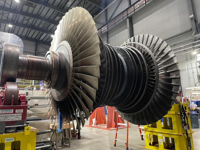
The expansion of steam refers to the process where steam undergoes an increase in volume as it moves from a higher pressure to a lower pressure. This expansion is a crucial part of many steam-based systems, particularly in power generation.
Here’s how the expansion of steam typically occurs in the context of a steam turbine in a power plant:
- High-Pressure Steam:
- Steam is generated in a boiler at high pressure and temperature. This high-pressure steam is directed towards the blades of a steam turbine.
- Turbine Blades:
- As the high-pressure steam flows over the blades of the turbine, it imparts its high kinetic energy to the blades, causing them to spin.
- Mechanical Work:
- The spinning turbine blades are connected to a shaft, and as the blades turn, they perform mechanical work on the shaft. This mechanical work is transferred to a generator, where it is converted into electrical energy.
- Expansion:
- As the steam passes through the turbine blades, it undergoes a significant expansion. The pressure and temperature of the steam decrease, and its volume increases. This is due to the conversion of the steam’s energy into mechanical work.
- Low-Pressure Steam:
- The steam exiting the turbine is now at a lower pressure and temperature. In some cases, this low-pressure steam may be directed to additional turbine stages to extract more work from the steam.
- Condensation (Optional):
- In certain power generation cycles, the low-pressure steam may be condensed back into water, and the water is then returned to the boiler to begin the process again.
The expansion of steam in a turbine is a key step in converting thermal energy into mechanical energy, which is then further transformed into electrical energy. The efficiency of this process is influenced by factors such as the design of the turbine, the pressure and temperature of the steam, and the overall design of the power plant.
It’s worth noting that the expansion of steam can also occur in other applications beyond power generation, such as in industrial processes where steam is used for mechanical work or heating. Understanding and controlling the expansion process are critical for optimizing the performance and efficiency of steam-based systems.
High-Pressure Steam
High-pressure steam refers to steam that is generated at a pressure significantly above atmospheric pressure. The specific pressure considered “high” can vary depending on the context, but in the realm of power generation and industrial processes, high-pressure steam is typically generated at pressures exceeding 15 psi (pounds per square inch) or 1.03 bar.
Here are key characteristics and applications of high-pressure steam:
- Generation in Boilers:
- High-pressure steam is often generated in specialized boilers designed to handle the higher pressures. These boilers can be found in power plants, industrial facilities, and other settings where the high-energy content of steam is required for various applications.
- Power Generation:
- In power plants, high-pressure steam is crucial for driving steam turbines. The expansion of high-pressure steam in turbines is used to generate mechanical work, which is then converted into electricity by generators.
- Industrial Processes:
- High-pressure steam is widely used in various industrial processes. Industries such as chemical, petrochemical, and manufacturing utilize high-pressure steam for tasks like sterilization, heating, and powering equipment.
- Heat Transfer:
- High-pressure steam is an effective medium for heat transfer due to its high energy content. It is used in heat exchangers, where it can transfer thermal energy to fluids or surfaces.
- Cogeneration (Combined Heat and Power):
- High-pressure steam is often employed in cogeneration systems where both electricity and useful heat are generated from the same energy source. The high-temperature steam can be used for industrial processes, and the remaining thermal energy can be converted into electricity.
- District Heating:
- In some district heating systems, high-pressure steam is used to distribute heat for residential and commercial heating applications.
- Quality and Safety Considerations:
- The quality and safety of high-pressure steam are crucial considerations. Steam at higher pressures and temperatures can cause more severe burns and injuries, and proper safety measures, including pressure relief devices, are essential.
- Boiler Design:
- Boilers designed for high-pressure steam must meet stringent safety and engineering standards. The construction and materials used in high-pressure boilers are carefully selected to withstand the elevated pressures and temperatures.
The selection of high-pressure steam is often driven by the specific requirements of the application. For instance, processes that demand high temperatures or high energy density may benefit from the use of high-pressure steam. However, it’s important to design and operate systems handling high-pressure steam with great care to ensure safety and efficiency. Regular maintenance, monitoring, and adherence to safety guidelines are critical aspects of managing high-pressure steam systems.
Turbine Blades
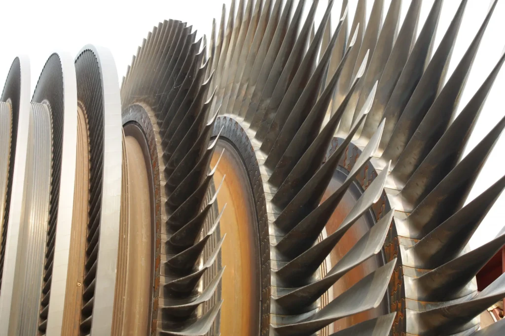
Turbine blades are a crucial component in steam turbines, gas turbines, and some types of water turbines. These blades play a key role in converting the kinetic energy of a moving fluid (steam, gas, or water) into mechanical energy that can be used to drive a generator or perform other types of work. Here’s an overview of turbine blades and their functions:
- Function:
- The primary function of turbine blades is to extract energy from a high-velocity fluid (steam or gas) and convert it into rotational mechanical energy. This rotational energy is then used to drive a generator or other machinery.
- Types of Turbine Blades:
- There are different types of turbine blades based on the specific requirements and design of the turbine. Two common types are:
- Impulse Blades: These blades operate on the principle of impulse. The high-velocity fluid (steam or gas) impacts the blades, causing them to rotate.
- Reaction Blades: These blades operate on the principle of both impulse and reaction. The fluid expands as it passes through the blades, causing both an impulse and a reaction force that drives the turbine.
- There are different types of turbine blades based on the specific requirements and design of the turbine. Two common types are:
- Material and Design:
- Turbine blades are typically made from high-strength materials that can withstand high temperatures and mechanical stresses. Common materials include high-alloy steels, superalloys, and advanced materials like ceramics and composites. The design of the blades is aerodynamically optimized to maximize efficiency and minimize losses.
- Cooling Systems:
- In gas turbines and certain steam turbines, where temperatures can reach extremely high levels, cooling systems are often integrated into the turbine blades. These systems help prevent overheating and maintain the structural integrity of the blades.
- Blade Profiles:
- Turbine blades have specific aerodynamic profiles designed to efficiently extract energy from the fluid. The shape of the blade is critical in maximizing the conversion of kinetic energy into mechanical energy.
- Arrangement:
- Turbine blades are arranged in rows, with each row designed to extract additional energy from the fluid. The arrangement may include multiple stages, each consisting of a set of rotating blades (rotor) and a set of stationary blades (stator).
- Manufacturing Processes:
- Turbine blades are often manufactured using precision casting or machining techniques to achieve the required shapes and tolerances. The manufacturing process is crucial to maintaining the aerodynamic efficiency of the blades.
- Maintenance:
- Turbine blades undergo significant stresses during operation, and proper maintenance is essential to ensure their performance and longevity. Regular inspections, repairs, and, if necessary, replacements are part of turbine maintenance procedures.
Turbine blades are critical components in power generation, aviation, and industrial applications. The efficiency and performance of turbines depend significantly on the design, material, and condition of the blades. Advances in materials and manufacturing technologies continue to improve the efficiency and reliability of turbine blades in various applications.
Mechanical Work
The mechanical work of a steam turbine is a result of the conversion of thermal energy in the form of high-pressure, high-temperature steam into mechanical energy, which is then used to drive a generator or perform other types of mechanical work. Here’s an overview of how a steam turbine generates mechanical work:
- Steam Generation:
- Steam is generated in a boiler by heating water. The heat source can be various, including burning fossil fuels (coal, natural gas, oil), using nuclear reactions, or harnessing renewable energy sources.
- High-Pressure Steam:
- The steam produced in the boiler is at high pressure and temperature. This high-pressure steam carries a significant amount of thermal energy.
- Expansion in the Turbine:
- The high-pressure steam is directed into the steam turbine. As the steam flows through the turbine blades, it undergoes a process of expansion. This expansion is a key aspect of the conversion of thermal energy into mechanical energy.
- Turbine Blades:
- The expansion of steam causes the turbine blades to rotate. There are two main types of steam turbines based on the principles of operation: impulse turbines and reaction turbines. In impulse turbines, the high-velocity steam impacts the blades, causing them to rotate. In reaction turbines, both the velocity and pressure of the steam change as it passes through the blades, generating rotational motion.
- Rotation of the Turbine Shaft:
- The rotating turbine blades are connected to a shaft. As the blades turn, they impart rotational motion to the shaft.
- Generator Connection:
- The shaft of the turbine is connected to a generator. The mechanical rotation of the shaft is used to turn the generator rotor within a magnetic field, inducing an electric current in the generator windings.
- Generation of Electricity:
- The electric current generated in the generator is then transmitted through the power grid for use in homes, industries, or other applications.
- Exhaust and Condensation:
- After passing through the turbine, the steam is at a lower pressure and temperature. In many power plants, the steam is then directed to a condenser, where it is condensed back into water. The condensed water is returned to the boiler to be reheated and reused in the steam cycle.
The overall efficiency of a steam turbine system depends on various factors, including the design of the turbine, the quality of steam, and the control systems in place. Improvements in turbine design, materials, and control technology have led to more efficient and reliable steam turbines in power generation and industrial applications.
Expansion
Expansion, in a thermodynamic context, refers to the process by which a substance undergoes a change in volume as a result of an increase in temperature or a decrease in pressure. Expansion can occur in various states of matter, including gases, liquids, and solids. Here, I’ll briefly explain expansion in the context of gases and liquids:
- Gas Expansion:
- In gases, expansion is a response to an increase in temperature or a decrease in pressure. When a gas is heated, its molecules gain kinetic energy and move more rapidly, leading to an increase in pressure and volume. The relationship between pressure, volume, and temperature in a gas is described by the ideal gas law (PV = nRT), where P is pressure, V is volume, n is the number of moles of gas, R is the gas constant, and T is temperature.
- For example, if you have a gas confined in a container and you heat it, the pressure inside the container will increase, and the gas will expand to occupy a larger volume.
- Liquid Expansion:
- In liquids, expansion primarily occurs due to an increase in temperature. When a liquid is heated, its molecules gain energy, causing them to move more vigorously and increasing the average separation between molecules. This results in an increase in the volume of the liquid.
- An everyday example of liquid expansion is the expansion of water when heated. When you heat water, it expands and can lead to the rising of liquid levels in containers.
- Thermal Expansion in Solids:
- In solids, expansion occurs when the material is heated. This is known as thermal expansion. When a solid is heated, its molecules vibrate more rapidly, causing the material to expand. Different materials have different coefficients of thermal expansion, which describe how much they expand or contract for a given change in temperature.
- The expansion and contraction of materials due to temperature changes are critical considerations in construction, engineering, and the design of structures and components.
Expansion has practical implications in various fields, and it’s important to account for these changes in real-world applications. For instance, in the design of bridges, buildings, and pipelines, engineers need to consider the potential expansion and contraction of materials due to temperature variations to prevent structural damage or failure. Similarly, the study of gas expansion is fundamental to the understanding of thermodynamics and the operation of heat engines, including steam turbines and internal combustion engines.
Low-Pressure Steam
Low-pressure steam refers to steam that is generated or used at a pressure lower than atmospheric pressure. In the context of steam, pressure is a crucial parameter that affects the temperature, density, and energy content of the steam. Low-pressure steam is often employed in various industrial, commercial, and residential applications where lower temperature and pressure conditions are suitable. Here are some key points about low-pressure steam:
- Pressure Range:
- While there is no strict definition for “low-pressure” steam, it generally refers to steam generated at pressures below 15 pounds per square inch (psi) or 1.03 bar. However, the specific pressure range can vary depending on the application and industry.
- Applications:
- Low-pressure steam has a wide range of applications, including but not limited to:
- Heating Systems: Low-pressure steam is used in heating systems for space heating in buildings, particularly in older systems where steam boilers are employed.
- Industrial Processes: Certain industrial processes require steam for heating, humidification, or specific manufacturing operations. Low-pressure steam can be suitable for these applications.
- Food Processing: In food processing, low-pressure steam is often used for tasks like sterilization, cooking, and maintaining controlled temperatures.
- Low-pressure steam has a wide range of applications, including but not limited to:
- Temperature and Energy Content:
- Steam pressure is directly related to its temperature and energy content. Low-pressure steam will have a lower temperature compared to high-pressure steam. While it may not carry as much energy per unit volume, it can still provide sufficient heat for many applications.
- Boiler Design:
- Boilers designed to produce low-pressure steam may have different specifications and safety features compared to high-pressure boilers. The design considerations include maintaining the required temperature and pressure for the intended application.
- Safety Considerations:
- While the safety risks associated with low-pressure steam are generally lower than those with high-pressure steam, proper safety measures, including pressure relief devices and regular maintenance, are still essential to prevent accidents and ensure safe operation.
- Condensate Handling:
- Low-pressure steam systems often deal with condensate, which is the liquid water formed as steam gives up its latent heat. Proper handling of condensate is important for system efficiency and preventing water hammer.
- Energy Efficiency:
- The use of low-pressure steam in certain applications can contribute to energy efficiency, especially when the lower pressure meets the requirements of the process. It is essential to match the steam characteristics to the needs of the specific application.
Understanding the requirements and characteristics of the application is crucial when determining whether low-pressure steam is suitable. It is commonly used in systems where the energy requirements and safety considerations align with the characteristics of low-pressure steam.
Condensation
Condensation is the process by which a substance changes its physical state from a gas or vapor to a liquid. This phase transition occurs when the temperature of the substance decreases to the point where its vapor pressure equals the atmospheric pressure. Condensation is a common natural phenomenon with widespread applications in various fields. Here are key aspects of condensation:
- Temperature Reduction:
- Condensation occurs when a gas or vapor is cooled. As the temperature of the substance decreases, its molecular movement slows down, and the molecules come together to form a liquid.
- Vapor Pressure:
- The transition from a gas to a liquid during condensation is influenced by vapor pressure. Vapor pressure is the pressure exerted by a vapor when it is in equilibrium with its liquid phase. When the vapor pressure equals the atmospheric pressure, condensation occurs.
- Atmospheric Conditions:
- Atmospheric pressure plays a significant role in condensation. As the temperature drops, the atmospheric pressure remains relatively constant. When the vapor pressure of a substance matches the atmospheric pressure, condensation begins.
- Dew Point:
- The temperature at which air becomes saturated with moisture and dew or frost begins to form is known as the dew point. It represents the point at which condensation occurs in the atmosphere.
- Formation of Dew:
- Dew forms when moist air comes into contact with a surface that is colder than the air. The moisture in the air condenses on the cooler surface, forming water droplets.
- Formation of Clouds:
- In the atmosphere, condensation is a fundamental process in cloud formation. When warm, moist air rises and encounters cooler air at higher altitudes, the water vapor in the warm air condenses to form visible water droplets, leading to the creation of clouds.
- Condensation in Industrial Processes:
- Condensation is utilized in various industrial processes. For example, in refrigeration and air conditioning systems, a gas is compressed and then allowed to expand, leading to cooling and condensation of the refrigerant.
- Applications in Heat Exchangers:
- Condensation is used in heat exchangers to transfer heat from a vapor to a liquid state. This process is common in power plants, industrial processes, and HVAC systems.
- Reverse Process:
- The reverse of condensation is evaporation, where a liquid changes to a gas or vapor as it absorbs heat.
- Prevention of Condensation:
- Condensation can be managed by controlling temperature, humidity levels, and using insulation to prevent surfaces from becoming cooler than the dew point.
Understanding and controlling condensation are important in various contexts, from weather patterns and climate science to industrial processes and the design of HVAC systems. Managing condensation is crucial for preventing issues such as water damage, corrosion, and the formation of ice in different applications.
Blades and Rotors
In the context of a steam turbine, blades and rotors are integral components that play a crucial role in the conversion of thermal energy from steam into mechanical energy. Here’s an overview of the blades and rotors in a steam turbine:
Blades
- Turbine Blades:
- Function: Turbine blades are the primary components responsible for extracting energy from high-pressure, high-temperature steam and converting it into mechanical energy.
- Types:
- Impulse Blades: Convert the kinetic energy of high-velocity steam into mechanical energy through the impact of the steam on the blades.
- Reaction Blades: Operate on the principles of impulse and reaction, with steam expanding as it passes through the blades, generating both kinetic and pressure-driven forces.
- Blade Profiles:
- Turbine blades are designed with specific aerodynamic profiles to efficiently utilize the energy of the steam flow. The shape of the blades is critical for maximizing energy extraction and minimizing losses.
- Materials:
- Blades are typically made from high-strength materials capable of withstanding high temperatures and mechanical stresses. Superalloys, high-alloy steels, and advanced materials are commonly used.
- Cooling Systems:
- In some steam turbines, especially those in power plants where high temperatures are encountered, turbine blades may incorporate cooling systems to prevent overheating and maintain structural integrity.
Rotors
- Turbine Rotor:
- Function: The rotor is the rotating component of the steam turbine to which the turbine blades are attached. It is responsible for converting the rotational motion of the blades into mechanical work.
- Connection to Shaft: The rotor is connected to the shaft of the turbine. As the turbine blades rotate due to the impact of steam, the rotor, in turn, rotates, transferring mechanical energy to the shaft.
- Rotor Design:
- The design of the rotor is critical for the overall efficiency and performance of the steam turbine. It must be capable of withstanding the mechanical stresses induced by the rotation of the blades and the high-speed steam flow.
- Bearings and Seals:
- The rotor is supported by bearings that allow it to rotate smoothly. Seals are also employed to minimize steam leakage and maintain the efficiency of the turbine.
- Balancing:
- Proper balancing of the rotor is essential to prevent vibration and ensure the reliable and stable operation of the steam turbine. Unbalanced rotors can lead to mechanical issues and reduced efficiency.
- Materials:
- Rotor materials must possess high strength and fatigue resistance. The choice of materials depends on factors such as the turbine’s operating conditions and the design specifications.
The combination of turbine blades and rotor forms the core of a steam turbine, where the conversion of thermal energy to mechanical work takes place. This mechanical work is then used to drive a generator, producing electricity in power plants or performing other types of mechanical work in various industrial applications. The efficiency and reliability of the steam turbine depend significantly on the design, materials, and proper maintenance of these critical components.
Turbine Blades
Turbine blades are crucial components in turbines, which are devices that convert the energy of a moving fluid (such as steam, gas, or water) into mechanical energy. Turbines are widely used in various applications, including power generation, aviation, and industrial processes. Turbine blades play a central role in this energy conversion process. Here are key aspects of turbine blades:
Function
- Energy Extraction:
- Turbine blades are designed to extract energy from a high-velocity fluid (steam or gas) or from the kinetic energy of flowing water. The energy extraction results in the rotation of the turbine blades.
- Mechanical Work:
- As the turbine blades rotate, they perform mechanical work. This rotational motion can be used to drive a generator, produce electricity, or perform other types of mechanical work in industrial processes.
- Types of Turbines:
- Turbine blades are adapted to different types of turbines:
- Steam Turbines: Blades in steam turbines extract energy from high-pressure, high-temperature steam.
- Gas Turbines: Blades in gas turbines operate with high-velocity gases produced by combustion.
- Hydraulic Turbines: Blades in hydraulic turbines extract energy from flowing water.
- Turbine blades are adapted to different types of turbines:
Characteristics
- Aerodynamic Design:
- Turbine blades have specific aerodynamic profiles designed to efficiently capture the energy of the fluid. The shape of the blades is critical for maximizing energy extraction and minimizing losses.
- Materials:
- Turbine blades are typically made from materials that can withstand high temperatures, mechanical stresses, and corrosion. Common materials include high-alloy steels, superalloys, and advanced materials like ceramics and composites.
- Cooling Systems:
- In applications where temperatures are extremely high, such as in gas turbines or certain sections of steam turbines, turbine blades may incorporate cooling systems to prevent overheating and maintain structural integrity.
- Roots and Mounting:
- The root of the turbine blade is the part that attaches to the rotor. The mounting of blades on the rotor must be robust to withstand the mechanical forces during rotation.
Types of Turbine Blades
- Impulse Blades:
- Impulse blades operate on the principle of converting the kinetic energy of a high-velocity fluid into mechanical energy through the impact of the fluid on the blades. These blades are common in impulse turbines.
- Reaction Blades:
- Reaction blades operate on the principles of both impulse and reaction. The fluid expands as it passes through the blades, generating both kinetic and pressure-driven forces. Reaction blades are often used in reaction turbines.
Maintenance
- Balancing:
- Proper balancing of turbine blades is essential to prevent vibration and ensure the reliable and stable operation of the turbine.
- Inspections and Repairs:
- Regular inspections and, if necessary, repairs or replacements of turbine blades are crucial for maintaining efficiency and preventing unexpected failures.
Turbine blades represent a critical aspect of energy conversion systems and are designed with precision to maximize efficiency and reliability in various applications. Advances in materials and design continue to improve the performance of turbine blades in modern turbines.
Blade Profile
The blade profile, also known as the airfoil profile or blade shape, refers to the cross-sectional shape of a turbine or aircraft blade as seen from the direction of fluid flow (such as air or steam). The design of the blade profile is crucial for optimizing the aerodynamic performance of the blade and, consequently, the efficiency of the entire system. Here are key aspects of blade profiles:
Characteristics
- Aerodynamic Efficiency:
- The primary goal of designing a specific blade profile is to achieve high aerodynamic efficiency. This involves minimizing drag, maximizing lift, and ensuring smooth airflow over the blade surface.
- Lift and Drag:
- The shape of the blade profile determines its ability to generate lift, which is essential for extracting energy in turbines or providing lift in aircraft. The profile is also designed to minimize drag, as excessive drag can reduce efficiency.
- Angle of Attack:
- The angle of attack is the angle between the chord line (a straight line connecting the leading and trailing edges of the blade) and the direction of the fluid flow. The blade profile is carefully designed to optimize the angle of attack for different operating conditions.
- Chord Length:
- The chord length is the distance from the leading edge to the trailing edge along the chord line. Blade profiles are characterized by their chord length and shape, which influence the overall performance of the blade.
Common Blade Profiles
- NACA Airfoil Profiles:
- The National Advisory Committee for Aeronautics (NACA) developed a series of airfoil profiles with systematic numbering. NACA airfoils are widely used in aviation and turbomachinery applications.
- Symmetric and Asymmetric Profiles:
- Some blade profiles are symmetric, meaning the upper and lower surfaces are identical. Others are asymmetric, with different shapes on the upper and lower surfaces. Asymmetric profiles are often used for specific aerodynamic requirements.
- Cambered Profiles:
- Camber is the curvature of the blade’s upper and lower surfaces. Cambered profiles are designed with a curve to generate lift even at zero angle of attack, enhancing overall performance.
- Twisted Profiles:
- In certain applications, such as aircraft propellers, blade profiles may be twisted along their length to optimize performance across different sections of the blade.
Applications
- Aircraft Wings:
- Aircraft wings use specific airfoil profiles to achieve lift and control. The design of the wing profiles is crucial for the aerodynamic performance of the aircraft.
- Turbine Blades:
- Turbine blades in steam turbines, gas turbines, or wind turbines use carefully designed profiles to efficiently extract energy from the fluid (steam, gas, or wind).
- Propeller Blades:
- Propeller blades in marine applications or aircraft propulsion systems use specialized profiles to generate thrust efficiently.
- Fan Blades:
- Fan blades in HVAC systems or industrial fans use specific profiles for optimal airflow and energy efficiency.
Computational Fluid Dynamics (CFD)
- Simulation and Analysis:
- Advances in Computational Fluid Dynamics (CFD) allow engineers to simulate and analyze the performance of different blade profiles under various conditions before physical prototypes are built.
The selection of a specific blade profile depends on the application, operating conditions, and desired performance characteristics. Engineers use sophisticated design and analysis tools to optimize blade profiles for specific purposes, ensuring efficiency and reliability in diverse applications.
Materials
The materials used to manufacture turbine blades are carefully chosen to withstand the harsh conditions of high temperatures, pressures, and mechanical stresses encountered in turbine applications. Different types of turbines, such as steam turbines, gas turbines, and wind turbines, may require specific materials based on their operating environments. Here are common materials used for turbine blades:
1. Superalloys
- Applications: Gas Turbines, Steam Turbines
- Properties:
- High-temperature strength and creep resistance.
- Excellent corrosion resistance.
- Often contain nickel, cobalt, and other alloying elements.
- Able to withstand extreme temperature differentials.
2. Single-Crystal Alloys
- Applications: Gas Turbines, Aircraft Engines
- Properties:
- Uniform crystal structure provides superior high-temperature strength.
- Enhanced resistance to thermal fatigue.
- Used in the hottest sections of turbines.
3. Ceramic Matrix Composites (CMCs)
- Applications: Gas Turbines, High-Temperature Environments
- Properties:
- Excellent thermal and chemical stability.
- High strength at elevated temperatures.
- Lighter weight compared to metal alloys.
- Suitable for high-temperature sections of turbines.
4. Titanium Alloys
- Applications: Aircraft Engines, Some Gas Turbines
- Properties:
- High strength-to-weight ratio.
- Good corrosion resistance.
- Used in sections of turbines where lower weight is crucial.
5. Nickel-Based Alloys
- Applications: Gas Turbines, Steam Turbines
- Properties:
- Good high-temperature strength.
- Corrosion-resistant.
- Suitable for high-pressure and high-temperature sections of turbines.
6. Coating Materials
- Applications: Gas Turbines, Steam Turbines
- Properties:
- Thermal barrier coatings (TBCs) protect against high temperatures.
- Oxidation-resistant coatings extend the lifespan of the blades.
- Coatings can be applied to enhance durability and performance.
7. Composite Materials
- Applications: Wind Turbines
- Properties:
- Fiberglass, carbon fiber, or hybrid composites are used.
- High strength, low weight, and resistance to fatigue.
- Commonly used in the construction of blades for wind turbines.
8. High-Strength Steels
- Applications: Some Industrial Turbines
- Properties:
- High strength and toughness.
- Used in applications where high-temperature resistance is not the primary concern.
Considerations for Material Selection
- Temperature and Pressure:
- Materials must withstand the high temperatures and pressures specific to the operating conditions of the turbine.
- Corrosion Resistance:
- Corrosion-resistant materials are crucial, especially in steam turbines where moisture is present.
- Fatigue Resistance:
- Turbine blades experience cyclic loading, and materials must be fatigue-resistant to ensure long-term reliability.
- Weight Considerations:
- In aircraft engines and some gas turbines, lightweight materials such as titanium alloys are preferred to reduce weight and improve fuel efficiency.
- Manufacturing Processes:
- The manufacturing processes for turbine blades, such as casting or precision machining, may influence material selection.
- Advancements in Materials:
- Ongoing research and advancements in materials science lead to the development of new alloys and composites with improved properties.
The selection of materials for turbine blades is a critical aspect of turbine design, ensuring that the blades can withstand the extreme conditions and provide reliable and efficient performance over their operational lifespan.
Mechanical Work
The mechanical work of a steam turbine involves the conversion of thermal energy carried by high-pressure, high-temperature steam into rotational mechanical energy. This mechanical energy is then utilized to drive a generator, producing electricity or perform other types of mechanical work. The process of how a steam turbine generates mechanical work can be broken down into several key steps:
- Steam Generation:
- Steam is generated in a boiler by heating water using a heat source. This heat source can come from burning fossil fuels (coal, natural gas, oil), nuclear reactions, or other sources.
- High-Pressure Steam:
- The steam produced in the boiler is at high pressure and temperature. This high-pressure steam contains a significant amount of thermal energy.
- Expansion in the Turbine:
- The high-pressure steam is directed into the steam turbine. As the steam flows through the turbine blades, it undergoes a process of expansion. This expansion is essential for converting the thermal energy of the steam into mechanical energy.
- Turbine Blades:
- The expansion of steam causes the turbine blades to rotate. There are two main types of steam turbines based on the principles of operation: impulse turbines and reaction turbines. Impulse turbines utilize the impact of high-velocity steam on the blades, while reaction turbines operate on both impulse and reaction forces as steam expands through the blades.
- Rotation of the Turbine Shaft:
- The rotating turbine blades are connected to a shaft. As the blades turn, they impart rotational motion to the shaft.
- Generator Connection:
- The shaft of the turbine is connected to a generator. The mechanical rotation of the shaft is used to turn the generator rotor within a magnetic field, inducing an electric current in the generator windings.
- Generation of Electricity:
- The electric current generated in the generator is then transmitted through the power grid for use in homes, industries, or other applications.
- Exhaust and Condensation:
- After passing through the turbine, the steam is at a lower pressure and temperature. In many power plants, the steam is then directed to a condenser, where it is condensed back into water. The condensed water is returned to the boiler to be reheated and reused in the steam cycle.
The overall efficiency of a steam turbine system depends on various factors, including the design of the turbine, the quality of steam, and the control systems in place. Improvements in turbine design, materials, and control technology have led to more efficient and reliable steam turbines in power generation and industrial applications. The mechanical work generated by steam turbines is a fundamental aspect of converting heat into useful energy for various applications.
Exhaust
In the context of a steam turbine or any heat engine, the term “exhaust” refers to the outlet or discharge of the working fluid (steam, gas, or air) after it has passed through the turbine and performed work. The exhaust stage is a crucial part of the thermodynamic cycle, as it completes the energy conversion process and prepares the working fluid for the next cycle. Here are key points related to the exhaust stage:
- Lower Pressure and Temperature:
- As the working fluid passes through the turbine and performs mechanical work, its pressure and temperature decrease. By the time the fluid reaches the exhaust stage, it is at a lower pressure and temperature compared to its state before entering the turbine.
- Exit Velocity:
- The fluid leaving the turbine at the exhaust stage often has a significant velocity. This is a result of the expansion of the fluid as it passes through the turbine blades. The high-speed exhaust flow can be harnessed for certain applications, such as jet propulsion or wind power.
- Condensation (Steam Turbines):
- In steam turbines, the exhaust steam is typically directed to a condenser. The condenser is a heat exchanger that removes heat from the steam, causing it to condense back into liquid water. This condensed water is then returned to the boiler for reheating, completing the steam cycle.
- Recompression (Gas Turbines):
- In gas turbines, the exhaust gases may be directed to a device called a compressor. The compressor compresses the exhaust gases before they are released into the atmosphere. This recompression can enhance the overall efficiency of the gas turbine system.
- Environmental Considerations:
- The composition of the exhaust (such as in the case of gas turbines) is of environmental concern. The emissions from the exhaust may include pollutants, and efforts are made to minimize environmental impact through technologies like exhaust gas treatment systems.
- Jet Propulsion:
- In the context of jet engines, the exhaust is expelled at high speed to generate thrust. This is essential for propelling aircraft and other vehicles.
- Waste Heat Recovery:
- Some systems incorporate waste heat recovery from the exhaust to improve overall efficiency. Heat exchangers may be used to capture and utilize the thermal energy in the exhaust for other processes.
- Cyclic Process:
- The exhaust stage marks the completion of one cycle in the thermodynamic process. The working fluid, having given up some of its energy to perform work, is ready to be reintroduced into the system to begin a new cycle.
Understanding and optimizing the exhaust stage are crucial for maximizing the efficiency of a heat engine or turbine system. The design considerations for the exhaust depend on the specific application, whether it be power generation, propulsion, or industrial processes.
It’s worth noting that there are various types of boilers, each with its own design and application. The choice of boiler type depends on factors such as the intended use of steam, fuel availability, and efficiency considerations.
Steam generation is a fundamental process in many industries and plays a crucial role in power generation, manufacturing, and heating applications worldwide.
Types of Steam Turbines
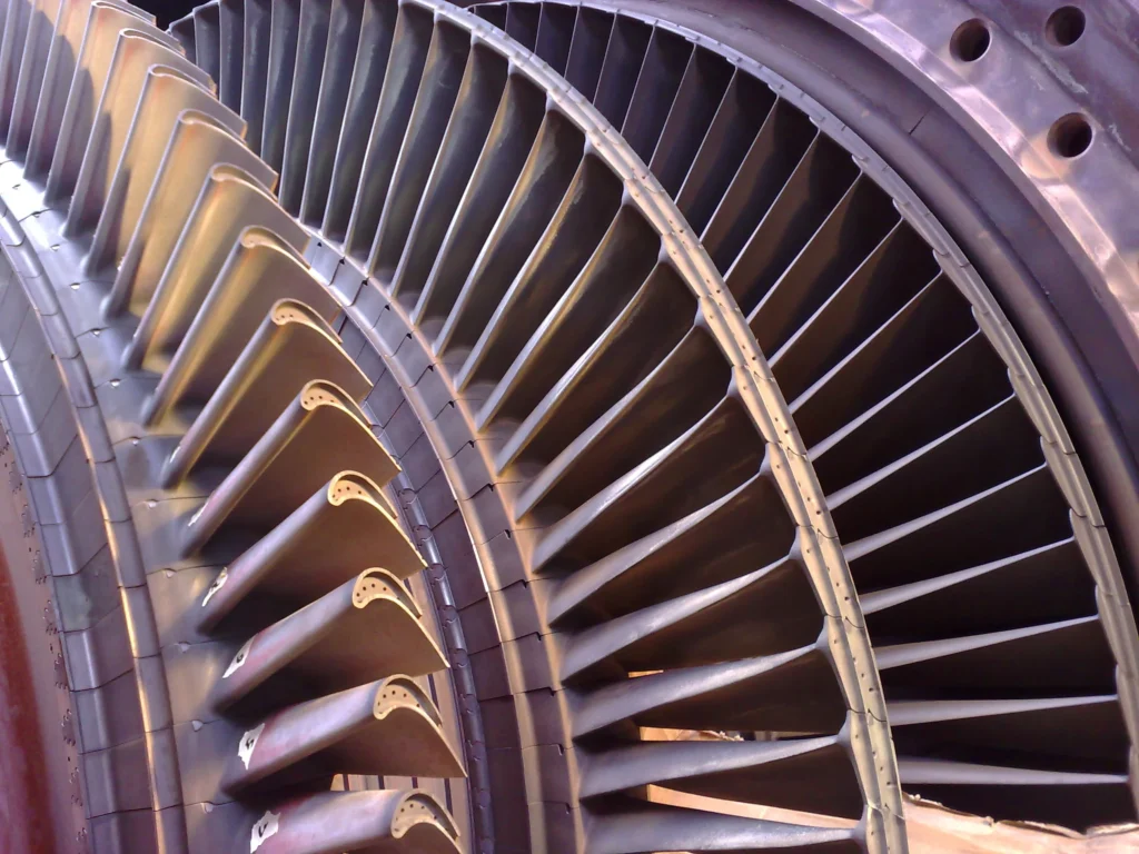
There are different types of steam turbines, including:
- Impulse Turbines: These turbines operate based on the principle of impulse, where high-velocity jets of steam are directed onto the turbine blades.
- Reaction Turbines: These turbines operate on the principle of both impulse and reaction, with steam expanding both as it passes over the blades and as it expands through them.
Steam turbines are crucial components in power plants, where they are often used in conjunction with other systems to generate electricity. They have been a key technology for power generation for over a century and continue to play a significant role in the production of electricity worldwide.
Small sized steam turbines are used in a variety of applications ranging from power generation in small-scale power plants to mechanical drives in industrial equipment. A steam turbine is a machine that converts thermal energy from steam into mechanical energy. Small sized steam turbines typically generate power in the range of a few kilowatts to several megawatts.
The design of small sized steam turbines typically involves several stages of blades that expand steam to create rotational force. The steam turbine rotor is typically mounted on bearings and rotates on a shaft. The steam is fed into the turbine through nozzles and directed onto the blades, causing the rotor to spin. The rotational force is transferred to a generator or other equipment to produce electricity or mechanical power.
Small sized steam turbines are used in various industries, including food processing, chemical, and pharmaceutical industries. They are used to power various machines and equipment, such as pumps, compressors, and fans. They are also used for combined heat and power (CHP) applications, where steam generated by a boiler is used to drive a steam turbine and produce both electricity and heat for industrial processes.
Steam Turbine Advantages
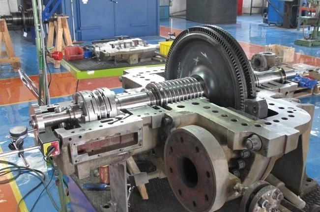
Advantages of small sized steam turbines include their high efficiency and reliability. They can also operate on a variety of fuels, including coal, oil, and natural gas. Additionally, small sized steam turbines can be designed to operate at varying loads, making them suitable for use in a wide range of applications.
However, there are also some disadvantages to using small sized steam turbines. They require regular maintenance to ensure optimal performance and can be expensive to operate and maintain. Additionally, the initial capital cost of a steam turbine can be high.
In summary, small sized steam turbines are an important source of power and mechanical energy in various industries. They offer high efficiency and reliability, making them suitable for a wide range of applications. However, they require regular maintenance and can be expensive to operate and maintain.
Dependability and versatility of equipment are vital to today’s process plants, pharmaceutical producers, mining interests, and a host of other users including, of course, petroleum, petrochemical, and chemical-process industries.
Operating pressures and temperatures are constantly rising; single-train capacities grow by leaps and bounds; continuity of service becomes a vital force, and the economy demands longer and longer periods between overhauls. Steam turbines are faithful partners to the process industries. They have proved their basic reliability and today are showing a new versatility by keeping pace with every demand for higher capacity, speed, and reliability.
Wherever you look in the process industries, there are more mechanical drive turbines; wherever you look, both horsepower and speed go up, year after year. And wherever you look, technological advances are being incorporated into modern steam turbines. Many manufacturers deserve to be recognized for their ability to solve the tougher steam
turbine application problems.
Through advanced planning, imaginative research, persistent development, and painstaking evaluation, engineers have in the last quarter of this century created a whole new turbine generation: machines of sizes and speeds that were only dreamed of a few decades ago. Multiflow exhausts, solid rotors, highspeed bearings, taller last-stage blades (“buckets”), cam-operated valve gear and controls, and other highly sophisticated control systems and computerized designs are a few of the innovations that helped make this progress
Knowledgeable manufacturers have available a wide selection of steam end designs, either single or multivalve, to meet any specific pressure and temperature conditions. The overwhelming majority of cases both industrial and cogeneration systems designed for electric power generation uses a simple, single-casing steam turbine. These turbines (Fig. 1.1) can be designed to provide operating flexibility to
economically utilize steam from a variety of sources to supply:
- Direct or geared power input for compressors, pumps, or other driven equipment
- Steam at the pressures and quantities required for integrated processes or lower-pressure turbines
- The electric power desired
- Cogenerated power for sale to the local utility
Overview of Steam Turbine
Fundamentals
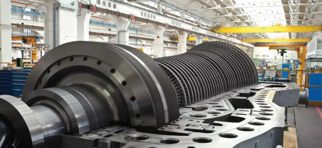
Before discussing turbine selection, let’s review how a steam turbine converts the heat energy of steam into useful work. The nozzles and diaphragms in a turbine are designed to direct the steam flow into well-formed, high-speed jets as the steam expands from inlet to exhaust pressure. These jets strike moving rows of blades mounted on the rotor. The blades convert the kinetic energy of the steam into the rotation energy of the shaft.
There are two principal turbine types: reaction and impulse. In a reaction turbine, the steam expands in both the stationary and moving blades. The moving blades are designed to utilize the steam jet energy of the stationary blades and to act as nozzles themselves. Because they are moving nozzles, a reaction force—produced by the pressure drop across them—supplements the steam jet force of the stationary blades. These combined forces cause rotation.
To operate efficiently the reaction turbine must be designed to minimize leakage around the moving blades. This is done by making most internal clearances relatively small. The reaction turbine also usually requires a balance piston (similar to those used in large centrifugal compressors) because of the large thrust loads generated. Because of these considerations, the reaction turbine is seldom used for mechanical drive in the United States, despite its occasionally higher initial efficiency. Reaction turbines are, nevertheless, in widespread use in Europe and the rest of the world.
They deserve to be discussed and will be dealt with later. The impulse turbine has little or no pressure drop across its moving blades. Steam energy is transferred to the rotor entirely by the steam jets striking the moving blades
Steam Turbine Description and Components
A steam turbine is a device that converts thermal energy from pressurized steam into mechanical work, which can then be used to generate electricity or perform other mechanical tasks. It is a type of heat engine that operates on the principle of converting the energy contained in high-pressure steam into rotational motion.
The basic components of a steam turbine include:
- Rotor: The rotor is the rotating part of the turbine that converts the steam’s kinetic energy into mechanical work. It typically consists of multiple blades or buckets attached to a central shaft.
- Stator: The stator is the stationary part of the turbine that contains fixed blades or nozzles. It guides the flow of steam onto the rotor blades, providing the necessary direction and control.
- Steam Inlet: The steam inlet is where high-pressure steam enters the turbine. It is connected to a steam source, such as a boiler, and the steam is directed into the turbine for expansion.
- Exhaust Outlet: The exhaust outlet is where the low-pressure steam exits the turbine after performing work. It is usually connected to a condenser or other steam utilization system.
- Governor: The governor is a control mechanism that regulates the steam flow and maintains a constant speed of the turbine, ensuring stable operation.
Steam turbines are commonly used in power plants to generate electricity. They can be categorized into different types based on their design and operational characteristics, such as condensing or non-condensing turbines, impulse or reaction turbines, and single-stage or multi-stage turbines.
The efficiency of a steam turbine depends on various factors, including the steam pressure and temperature, turbine design, and operating conditions. Steam turbines can achieve high efficiency levels, especially in combined cycle power plants where waste heat from the turbine is recovered and used to generate additional power.
Overall, steam turbines have been widely used for power generation due to their reliability, scalability, and ability to utilize a variety of fuel sources, including fossil fuels and renewable energy sources such as biomass or geothermal steam.
Rotor
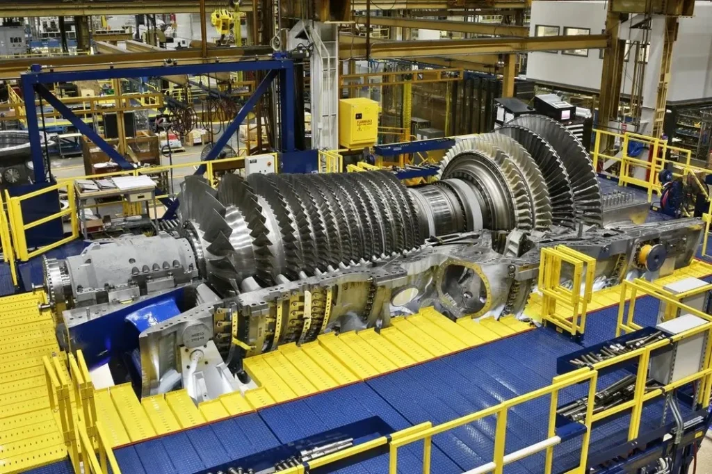
The rotor is a crucial component of a steam turbine. It is the rotating part of the turbine that converts the kinetic energy of the steam into mechanical work. The rotor typically consists of a central shaft and multiple blades or buckets attached to it.
The main function of the rotor is to extract energy from the high-pressure and high-temperature steam flowing through the turbine. As the steam passes over the blades, it imparts a force on them, causing the rotor to rotate. The rotation of the rotor is what generates the mechanical work that can be used for various applications, such as generating electricity in a power plant or driving industrial machinery.
The design and construction of the rotor are critical to ensure efficient and reliable operation of the steam turbine. The blades or buckets are shaped in a way that optimizes the flow of steam and maximizes the energy transfer. They are carefully engineered to withstand high temperatures, pressures, and centrifugal forces.
Depending on the type and size of the steam turbine, the rotor can have different configurations. In impulse turbines, the blades are arranged in a radial or axial configuration, and the steam acts on them in discrete stages. In reaction turbines, the blades are shaped to react to the steam continuously as it passes over them.
The rotor is connected to the generator or the mechanical load being driven by the turbine. The rotational motion of the rotor is transmitted to the generator or load through a coupling or a gearbox, where it is converted into electrical power or mechanical work, respectively.
Efficient and well-designed rotors are essential for the overall performance and output of a steam turbine. They undergo rigorous engineering analysis and testing to ensure they can withstand the operating conditions and deliver the desired power output while maintaining reliability and durability.
Stator
The stator is another important component of a steam turbine. It is the stationary part of the turbine that surrounds the rotor. The stator is responsible for directing and controlling the flow of steam as it passes through the turbine, converting the kinetic energy of the steam into mechanical work.
The primary function of the stator is to house the stationary blades or vanes that guide the flow of steam onto the rotor blades. These stationary blades are designed to optimize the flow of steam, ensuring efficient energy transfer and maximum power output. The stator blades are typically curved or angled to direct the steam in the desired direction and maintain a uniform flow.
In addition to guiding the steam flow, the stator also serves to support and protect the rotor and other internal components of the turbine. It provides structural stability and helps maintain the alignment of the rotor and stator blades.
The stator is typically constructed using high-quality materials that can withstand the high temperatures, pressures, and mechanical stresses encountered in the steam turbine. It is often made of steel or other alloys with excellent heat resistance and mechanical properties.
In large steam turbines, the stator is composed of multiple sections or stages, each with its set of stationary blades. These stages are designed to progressively extract energy from the steam as it passes through the turbine, improving the overall efficiency of the system.
The stator is an integral part of the steam turbine, working in conjunction with the rotor to convert steam energy into mechanical work. Together, they form a highly efficient and reliable power generation system used in various industries, including power plants, refineries, and industrial processes.
Steam Inlet
The steam inlet, also known as the steam admission or steam entry, is the point of entry for high-pressure steam into the steam turbine. It is a crucial component that allows the steam to enter the turbine and initiate the power generation process.
The steam inlet is typically located on the outer casing of the turbine and is connected to the steam source, such as a boiler or steam generator. The high-pressure steam flows through the steam inlet and enters the turbine at a specific angle and velocity.
To ensure efficient and controlled entry of steam into the turbine, the steam inlet is designed with various features. These include:
- Nozzles: The steam inlet may have a set of nozzles or guide vanes that help control the flow direction and velocity of the steam entering the turbine. These nozzles are adjustable and can be positioned to optimize the steam flow for maximum efficiency.
- Steam Strainers: Steam strainers or filters are sometimes installed at the steam inlet to remove any solid particles or impurities from the steam. These strainers help protect the turbine blades from damage and ensure smooth operation.
- Steam Control Valves: Steam control valves are often installed at the steam inlet to regulate the flow of steam into the turbine. These valves can adjust the steam flow rate and pressure, allowing for precise control of the turbine’s power output.
- Expansion Joints: Expansion joints are used at the steam inlet to accommodate thermal expansion and contraction of the turbine components. They help maintain the integrity of the turbine casing while allowing for the necessary movement caused by temperature variations.
The design and configuration of the steam inlet may vary depending on the specific type and size of the steam turbine. The goal is to ensure efficient steam flow, minimize pressure losses, and protect the turbine from any potential damage.
Overall, the steam inlet plays a critical role in the steam turbine’s operation by allowing high-pressure steam to enter the turbine and initiate the energy conversion process. Its design and functionality are crucial for optimizing turbine performance and ensuring reliable power generation.
Exhaust Outlet
The exhaust outlet, also known as the exhaust nozzle or exhaust diffuser, is the point of exit for the steam or gas after it has passed through the turbine and performed its work. It is an essential component of a steam turbine system as it allows the spent steam or gas to be discharged safely and efficiently.
The exhaust outlet is typically located at the opposite end of the turbine from the steam or gas inlet. It is designed to convert the high-velocity, high-pressure steam or gas into a lower-velocity, lower-pressure state before it is released into the surrounding environment or directed to further use, such as for heating or industrial processes.
The exhaust outlet performs several important functions:
- Pressure Reduction: The exhaust outlet is designed to gradually decrease the pressure of the steam or gas as it expands and flows through the turbine. This pressure reduction allows the steam or gas to exit the turbine at a lower pressure, minimizing the risk of sudden pressure changes that could damage the turbine or associated equipment.
- Velocity Control: The exhaust outlet helps control the velocity of the exhaust steam or gas as it exits the turbine. By gradually increasing the cross-sectional area of the outlet, the steam or gas velocity is reduced, which helps to minimize noise and prevent any potential damage to downstream components.
- Energy Recovery: In some cases, the exhaust outlet may be connected to a heat recovery system or condenser. This allows for the extraction of additional energy from the exhaust steam or gas by recovering heat or converting it into usable power. This improves the overall efficiency of the turbine system.
- Noise Reduction: The design of the exhaust outlet may incorporate features such as diffusers or silencers to reduce noise generated by the high-velocity exhaust steam or gas. This helps to meet noise regulations and maintain a quieter operating environment.
The specific design and configuration of the exhaust outlet may vary depending on the size, type, and application of the steam turbine. Factors such as exhaust pressure, flow rate, and temperature are considered in the design to optimize turbine performance and ensure safe operation.
Overall, the exhaust outlet is a critical component of a steam turbine system, responsible for safely and efficiently discharging the spent steam or gas. Its design aims to control pressure, velocity, and noise while allowing for energy recovery when applicable.
Governor of the Steam Turbine
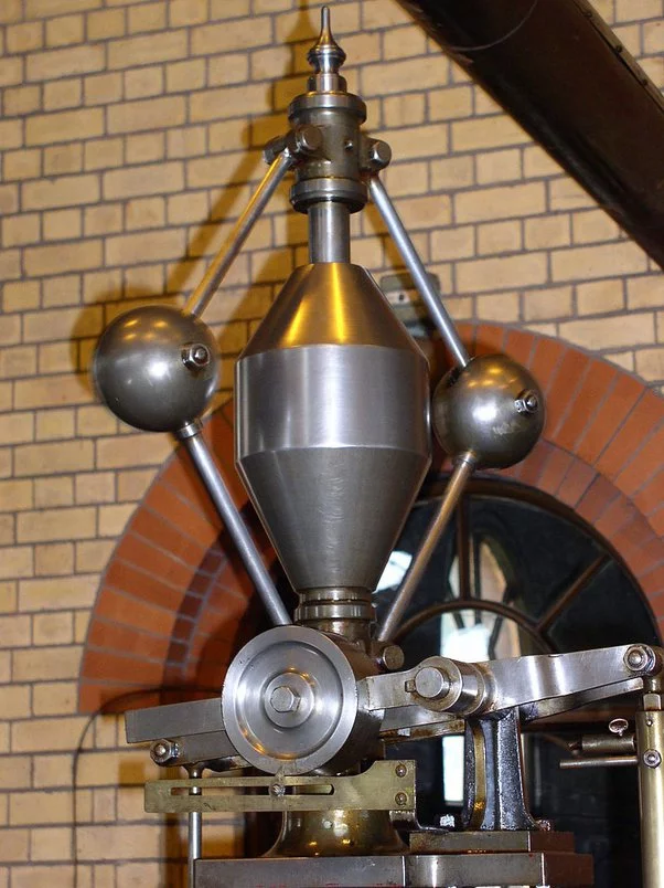
The governor is an important control device used in steam turbines to regulate the speed and output power of the turbine. Its main function is to maintain a constant rotational speed of the turbine within a desired range, regardless of changes in the load or steam conditions.
The governor operates based on the principle of feedback control, where it continuously monitors the speed of the turbine and adjusts the steam flow to maintain the desired speed. Here’s a brief overview of how the governor works:
- Speed Sensing: The governor is equipped with speed-sensing mechanisms such as centrifugal weights or magnetic pickups that detect the rotational speed of the turbine. These sensors provide input signals to the governor control system.
- Control System: The governor control system processes the speed signals and compares them to the desired speed setpoint. It calculates the error between the actual speed and the setpoint and determines the necessary adjustments to be made.
- Steam Flow Regulation: Based on the error signal, the governor control system adjusts the steam flow rate entering the turbine. This is typically achieved by modulating the steam control valves that regulate the steam flow. If the turbine speed is below the setpoint, the governor increases the steam flow, and if the speed is above the setpoint, it decreases the steam flow.
- Feedback Loop: The governor continuously monitors the turbine speed and makes ongoing adjustments to the steam flow to maintain the desired speed. It operates in a closed-loop feedback system, where it compares the measured speed with the setpoint and adjusts the steam flow accordingly.
The governor ensures stable operation of the steam turbine by responding to changes in load demand and maintaining a constant speed. It helps to prevent overspeed or underspeed conditions that could potentially damage the turbine or cause operational issues. Additionally, the governor provides a means of controlling the output power of the turbine, allowing it to respond to changes in the electrical grid or other power system requirements.
Modern steam turbines often utilize advanced electronic or digital governor systems that offer more precise control and flexibility. These systems may incorporate additional features such as load sharing between multiple turbines, protection functions, and communication interfaces for integration into broader control systems.
Overall, the governor plays a crucial role in the safe and efficient operation of steam turbines by regulating the turbine speed and power output to meet the desired operating conditions.
Steam Turbine Application Areas
Steam turbines are used in a wide variety of applications, including:
- Power generation: Steam turbines are the most common type of prime mover used in power plants to generate electricity. They are also used in combined heat and power (CHP) plants to generate both electricity and heat.
- Industrial processes: Steam turbines are used in a variety of industrial processes, such as oil refining, chemical processing, and papermaking. They are used to drive compressors, pumps, and other machinery.
- Marine propulsion: Steam turbines are used to power large ships, such as aircraft carriers and cruise ships.
- Transportation: Steam turbines are used to power some locomotives and other rail vehicles.
Here are some specific examples of how steam turbines are used in different industries:
- Power generation: In the power generation industry, steam turbines are used to drive generators to produce electricity. The steam is typically generated by a boiler, which is heated by burning fossil fuels or nuclear fuel. The steam then drives the turbine blades, which rotate the generator shaft. The generator shaft is connected to a rotor, which generates electricity as it rotates.
- Industrial processes: In the industrial process industry, steam turbines are used to drive a variety of machinery, such as compressors, pumps, and fans. Steam turbines are also used to generate heat for industrial processes, such as drying products and distilling liquids.
- Marine propulsion: In the marine propulsion industry, steam turbines are used to power large ships, such as aircraft carriers and cruise ships. The steam turbines drive propellers, which propel the ship through the water.
- Transportation: In the transportation industry, steam turbines are used to power some locomotives and other rail vehicles. Steam turbines are also used to power some electric power plants that are built on trains.
Steam turbines are a versatile and efficient type of prime mover that can be used in a wide variety of applications. They are a key component of the global energy infrastructure.
Power Generation with Steam Turbines
Steam turbines are used to generate electricity in power plants by converting the thermal energy of steam into mechanical energy. The steam is generated in a boiler by heating water with fossil fuels, nuclear fuel, or renewable energy sources such as solar or geothermal energy. The high-pressure steam is then fed to the steam turbine, where it expands and drives the turbine blades. The turbine blades are connected to a shaft, which rotates a generator to produce electricity.
There are two main types of steam turbines used in power generation:
- Condensing steam turbines: Condensing steam turbines are the most common type of steam turbine used in power plants. They operate by condensing the steam that exits the turbine back into water. This allows the turbine to operate at a higher efficiency.
- Backpressure steam turbines: Backpressure steam turbines are used in combined heat and power (CHP) plants to generate both electricity and heat. They operate by extracting some of the steam from the turbine before it is fully expanded. This steam is then used to provide heat for industrial processes or buildings.
Steam turbines are an efficient and reliable way to generate electricity. They are also very versatile and can be used to generate electricity from a variety of energy sources.
- Boiler: The boiler heats water to generate steam.
- Superheater: The superheater heats the steam to a higher temperature.
- Reheater: The reheater heats the steam after it has expanded through the high-pressure turbine.
- High-pressure turbine: The high-pressure turbine extracts some of the energy from the steam.
- Low-pressure turbine: The low-pressure turbine extracts the remaining energy from the steam.
- Condenser: The condenser condenses the steam back into water.
- Feedwater pump: The feedwater pump pumps the condensed water back to the boiler.
- Generator: The generator converts the mechanical energy of the turbine shaft into electricity.
Steam turbines play a vital role in the global energy infrastructure. They are a key component of the transition to a clean energy future, as they can be used to generate electricity from a variety of renewable energy sources.
Industrial Processes where Steam Turbine is Used
Steam turbines are used in a wide variety of industrial processes, including:
- Oil refining: Steam turbines are used to drive compressors, pumps, and other machinery in oil refineries. They are also used to generate heat for distillation processes.
- Chemical processing: Steam turbines are used to drive compressors, pumps, and other machinery in chemical plants. They are also used to generate heat for chemical reactions.
- Papermaking: Steam turbines are used to drive machinery in paper mills, such as pulpers, paper machines, and dryers. They are also used to generate heat for drying paper.
- Food and beverage processing: Steam turbines are used to drive machinery in food and beverage processing plants, such as conveyors, mixers, and cookers. They are also used to generate heat for sterilization and pasteurization processes.
- Textile manufacturing: Steam turbines are used to drive machinery in textile mills, such as spinners, weavers, and finishers. They are also used to generate heat for drying and dyeing textiles.
- Metalworking: Steam turbines are used to drive machinery in metalworking shops, such as rolling mills, presses, and saws. They are also used to generate heat for heat treatment processes.
Here are some specific examples of how steam turbines are used in different industrial processes:
- Oil refining: In the oil refining industry, steam turbines are used to drive compressors that compress crude oil to high pressures. The compressed oil is then fed to distillation columns, where it is separated into different fractions, such as gasoline, diesel fuel, and jet fuel. Steam turbines are also used to drive pumps that circulate oil through the refinery and to generate heat for distillation processes.
- Chemical processing: In the chemical processing industry, steam turbines are used to drive compressors that compress gases, such as air, nitrogen, and hydrogen. The compressed gases are then used in a variety of chemical processes, such as ammonia production and fertilizer manufacturing. Steam turbines are also used to drive pumps and mixers, and to generate heat for chemical reactions.
- Papermaking: In the papermaking industry, steam turbines are used to drive pulpers that break down wood chips into fibers. The fibers are then mixed with water and chemicals to form a slurry, which is then fed to a paper machine. The paper machine forms the slurry into a sheet of paper, which is then dried and finished. Steam turbines are used to drive all of the machinery in a paper mill, as well as to generate heat for drying paper.
- Food and beverage processing: In the food and beverage processing industry, steam turbines are used to drive conveyors that transport food and beverage products through the processing plant. They are also used to drive mixers and cookers, and to generate heat for sterilization and pasteurization processes.
- Textile manufacturing: In the textile manufacturing industry, steam turbines are used to drive spinners that spin yarn from fibers. The yarn is then fed to a weaver to create fabric, which is then finished. Steam turbines are used to drive all of the machinery in a textile mill, as well as to generate heat for drying and dyeing textiles.
- Metalworking: In the metalworking industry, steam turbines are used to drive rolling mills that roll metal sheets and plates into different shapes. They are also used to drive presses that punch or stamp metal parts, and saws that cut metal. Steam turbines are used to drive all of the machinery in a metalworking shop, as well as to generate heat for heat treatment processes.
Steam turbines are an essential part of many industrial processes. They provide a reliable and efficient way to power machinery and generate heat.
Marine propulsion with Steam Turbines
Steam turbines have been used for marine propulsion for over a century. They were the dominant form of marine propulsion in the early 20th century, but they have since been largely replaced by diesel engines. However, steam turbines are still used in some large ships, such as aircraft carriers and cruise ships.
Steam turbines are a good choice for marine propulsion because they are efficient and reliable. They can also be used to generate a lot of power, which is needed for large ships. However, steam turbines are also complex and expensive to build and maintain.
- Boiler: The boiler heats water to generate steam.
- Superheater: The superheater heats the steam to a higher temperature.
- Reheater: The reheater heats the steam after it has expanded through the high-pressure turbine.
- High-pressure turbine: The high-pressure turbine extracts some of the energy from the steam.
- Low-pressure turbine: The low-pressure turbine extracts the remaining energy from the steam.
- Condenser: The condenser condenses the steam back into water.
- Feedwater pump: The feedwater pump pumps the condensed water back to the boiler.
- Propeller: The propeller is driven by the turbine shaft and propels the ship through the water.
Steam turbine propulsion systems are typically used in large ships, such as aircraft carriers and cruise ships. These ships need a lot of power to propel them through the water, and steam turbines can provide that power.
Steam turbines are also used in some submarines. Submarines need to be able to operate quietly, and steam turbines can be operated very quietly. This is important because it allows submarines to avoid detection.
Overall, steam turbines are a good choice for marine propulsion because they are efficient, reliable, and can generate a lot of power. However, they are also complex and expensive to build and maintain.
Steam Turbines
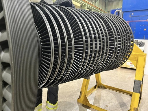
Steam turbines are remarkable machines that convert thermal energy from steam into mechanical work, widely used in power generation, industrial processes, and propulsion systems. They operate on the principle of expanding high-pressure steam through a series of blades, causing rotation that can drive generators or other machinery. Over time, engineers have developed various types of steam turbines, each designed to optimize efficiency, performance, and application-specific requirements. Below is an exploration of the primary types of steam turbines, their configurations, and their uses.
1. Impulse Turbines
Impulse turbines operate based on the impulse principle, where high-pressure steam is directed through nozzles to form high-velocity jets that strike the turbine blades. The kinetic energy of the steam is transferred to the blades, causing the rotor to spin. In this design, the pressure drop occurs entirely in the nozzles, and the blades experience no significant pressure change as the steam passes through. A classic example of an impulse turbine is the De Laval turbine, which features a single stage and is known for its simplicity and high rotational speeds. Another well-known design is the Curtis turbine, which uses multiple stages of moving and stationary blades to extract energy more efficiently in a compact form.
Impulse turbines are often used in small-scale power generation or as the high-pressure stages in larger systems. Their advantages include simplicity and the ability to handle high-pressure steam effectively, though they may be less efficient at lower speeds or with variable loads.
2. Reaction Turbines
In contrast to impulse turbines, reaction turbines rely on both pressure drop and steam expansion across the turbine blades themselves. As steam passes through the moving blades, it accelerates and expands, creating a reactive force (similar to how a rocket works) that drives the rotor. This design was pioneered by Sir Charles Parsons, and the Parsons turbine remains a foundational example. Reaction turbines typically feature multiple stages, with alternating rows of fixed (stator) and moving (rotor) blades, allowing for gradual energy extraction and higher efficiency.
Reaction turbines are widely used in large power plants because they excel at handling lower-pressure steam and can achieve greater efficiency over a range of operating conditions. However, they are more complex and costly to manufacture due to the precision required in blade design and staging.
3. Combination (Impulse-Reaction) Turbines
Many modern steam turbines combine impulse and reaction principles to optimize performance across different pressure ranges. For example, the high-pressure stages might use an impulse design to handle the initial steam conditions, while the low-pressure stages transition to a reaction design for better efficiency as the steam expands. This hybrid approach allows turbines to adapt to a wide variety of operating conditions, making them common in large-scale electricity generation plants.
4. Back-Pressure Turbines
Back-pressure turbines exhaust steam at a pressure higher than atmospheric pressure, allowing the exhaust steam to be used for industrial processes like heating, drying, or driving other machinery. These turbines are often found in cogeneration systems, where both electricity and heat are needed, such as in paper mills, chemical plants, or district heating systems. While they sacrifice some efficiency in power generation compared to condensing turbines, their ability to provide dual outputs makes them highly economical in specific applications.
5. Condensing Turbines
Condensing turbines are designed to maximize power output by exhausting steam into a vacuum, typically created by a condenser. This lowers the back pressure, allowing the steam to expand further and extract more energy. These turbines are the backbone of most large-scale power plants, including coal, nuclear, and combined-cycle gas plants. Their high efficiency comes at the cost of requiring a cooling system (often water-based), which adds complexity and environmental considerations.
6. Extraction Turbines
Extraction turbines are a versatile subtype that allow steam to be “extracted” at intermediate pressures from various stages of the turbine. This extracted steam can be used for industrial processes or heating, while the remaining steam continues through the turbine to generate power. These turbines are common in facilities needing both electricity and steam at different pressure levels, offering flexibility and efficiency in combined heat and power (CHP) systems.
7. Reheat Turbines
Reheat turbines improve efficiency by incorporating a reheat cycle. After passing through the high-pressure stages, steam is sent back to the boiler to be reheated before entering the intermediate- or low-pressure stages. This process increases the average temperature at which heat is added, boosting the turbine’s thermodynamic efficiency. Reheat designs are standard in large, high-efficiency power plants, though they require additional equipment and control systems.
8. Low-Pressure, Intermediate-Pressure, and High-Pressure Turbines
In large power plants, steam turbines are often divided into separate sections based on steam pressure: high-pressure (HP), intermediate-pressure (IP), and low-pressure (LP) turbines. These sections are typically mounted on a single shaft and work together to extract energy as the steam expands from high to low pressure. Each section is optimized for its specific pressure range, with blade sizes and designs varying accordingly—HP turbines have smaller, robust blades, while LP turbines have larger blades to handle the expanded, lower-pressure steam.
9. Single-Stage vs. Multi-Stage Turbines
Steam turbines can also be classified by the number of stages. Single-stage turbines, like the De Laval design, are simple and compact, suitable for small-scale or high-speed applications. Multi-stage turbines, such as those used in power plants, consist of multiple sets of blades, allowing for gradual energy extraction and higher efficiency. Multi-stage designs dominate in large-scale applications due to their ability to handle large steam volumes and pressure drops.
Applications and Considerations
Each type of steam turbine serves a specific purpose. Impulse turbines might power small generators or pumps, while reaction turbines drive massive gigawatt-scale power stations. The choice of turbine type depends on factors like steam conditions (pressure, temperature, and flow rate), desired output (power, heat, or both), and operational constraints (space, cost, and maintenance). Let’s dive deeper into each type with additional details on their design, mechanics, and real-world applications.
1. Impulse Turbines
Impulse turbines rely on the conversion of steam’s potential energy into kinetic energy before it interacts with the blades. The steam is accelerated through stationary nozzles, which are precisely shaped (often converging-diverging nozzles) to achieve supersonic velocities. When this high-speed jet hits the turbine’s bucket-shaped blades, the momentum transfer causes rotation. The blades are symmetrically designed to minimize axial thrust, and the steam exits at roughly the same pressure it entered, having lost much of its kinetic energy.
- De Laval Turbine: Invented by Gustaf de Laval in the late 19th century, this single-stage turbine was revolutionary for its time. It’s compact, with a single row of blades, and can reach speeds exceeding 30,000 RPM, making it ideal for driving high-speed machinery like centrifugal pumps or small generators. However, its efficiency drops with varying loads, limiting its use to niche applications.
- Curtis Turbine: Developed by Charles G. Curtis, this design adds a velocity-compounding feature. Steam passes through multiple rows of moving blades interspersed with stationary blades that redirect the flow. This staged approach reduces the rotor speed (compared to De Laval) while extracting more energy, making it suitable for early electrical generation systems.
- Applications: Impulse turbines shine in high-pressure, low-flow scenarios, such as topping turbines in combined-cycle plants or standalone units in remote locations. They’re less common in modern large-scale power generation due to efficiency limitations but remain critical in specialized industrial setups.
2. Reaction Turbines
Reaction turbines operate on a different principle: the blades act as nozzles themselves, accelerating and expanding the steam as it flows through. This creates a drop in pressure across each stage, generating a reactive force that drives the rotor. The stator blades (fixed) direct steam onto the rotor blades (moving), and the process repeats across multiple stages. The degree of reaction—typically around 50% in a Parsons turbine—refers to the proportion of energy extracted via reaction versus impulse.
- Parsons Turbine: Sir Charles Parsons’ 1884 invention introduced the multi-stage reaction concept, a breakthrough that transformed power generation. His turbines feature dozens or even hundreds of stages, with blade heights increasing as steam expands. This gradual energy extraction maximizes efficiency, especially at lower pressures.
- Design Nuances: Reaction turbine blades are airfoil-shaped, requiring precise manufacturing to handle aerodynamic forces and steam expansion. The rotor and stator blades are often paired in a 1:1 ratio, creating a balanced, continuous flow. Axial thrust is a challenge, necessitating thrust bearings to stabilize the rotor.
- Applications: Reaction turbines dominate in large fossil-fuel, nuclear, and geothermal power plants due to their scalability and efficiency at handling high steam volumes. They’re less suited to small-scale or high-pressure-only applications, where impulse designs may outperform.
3. Combination (Impulse-Reaction) Turbines
Combination turbines blend the strengths of both designs. The high-pressure section often uses impulse stages to manage the intense initial conditions (e.g., 200 bar, 540°C), where nozzles and robust blades excel. As steam pressure drops, the turbine transitions to reaction stages, leveraging expansion for efficiency in the intermediate- and low-pressure zones. This hybrid layout is tailored to the steam cycle’s thermodynamic profile.
- Mechanics: The transition between impulse and reaction stages is seamless, with blade designs and staging adjusted to match pressure gradients. For example, early stages might feature pure impulse (100% pressure drop in nozzles), while later stages approach 50% reaction.
- Advantages: This design optimizes efficiency across a wide pressure range, reduces mechanical stress, and allows for compact yet powerful turbines. It’s a staple in modern supercritical and ultra-supercritical coal plants, where steam conditions push material limits.
- Applications: Found in utility-scale power generation, especially where efficiency and output must be maximized, such as in combined-cycle plants integrating gas and steam turbines.
4. Back-Pressure Turbines
Back-pressure turbines exhaust steam at a usable pressure (e.g., 5-20 bar) rather than condensing it into a vacuum. The exhaust steam retains significant thermal energy, making it ideal for downstream processes. These turbines often operate in a non-condensing mode, with exhaust piped directly to industrial systems.
- Design Details: Simpler than condensing turbines, they lack a condenser and cooling system, reducing capital costs. Blade staging is optimized for a specific exhaust pressure, balancing power output with steam quality for process use.
- Efficiency Trade-Off: Electrical efficiency is lower than condensing turbines (since less energy is extracted), but total energy efficiency soars when process heat is factored in—sometimes exceeding 80% in cogeneration setups.
- Applications: Common in industries like pulp and paper (for drying), sugar refining (for evaporation), and petrochemical plants (for heating). They’re also used in district heating systems, where exhaust steam warms buildings.
5. Condensing Turbines
Condensing turbines push efficiency to the limit by exhausting steam into a vacuum (e.g., 0.05 bar), created by a condenser cooled with water or air. This maximizes the pressure drop across the turbine, extracting nearly all available energy from the steam.
- Mechanics: The low-pressure stages feature massive blades—sometimes over a meter long—to handle the high-volume, low-density steam. Condensers require significant infrastructure, including cooling towers or river/ocean water systems, adding complexity.
- Materials and Challenges: LP blades face erosion from wet steam (containing water droplets), necessitating alloys like titanium or protective coatings. Vacuum maintenance is critical, as leaks reduce efficiency.
- Applications: The backbone of baseload power plants—coal, nuclear, and gas-fired—where maximum electrical output is the goal. They’re less practical in small-scale or heat-focused systems due to their reliance on cooling.
6. Extraction Turbines
Extraction turbines offer flexibility by allowing steam to be tapped at intermediate points. Valves control the extraction process, diverting steam at specific pressures (e.g., 10 bar for heating, 2 bar for feedwater preheating) while the rest continues to the condenser.
- Design Complexity: Multiple extraction points require sophisticated control systems and additional piping. Blade staging must account for variable flow rates, as extraction reduces steam volume in later stages.
- Benefits: They balance power and heat output, adapting to fluctuating demands. Efficiency remains high when extraction is optimized with process needs.
- Applications: Prevalent in refineries, steel mills, and CHP plants, where steam serves dual purposes—electricity for operations and heat for processes like distillation or drying.
7. Reheat Turbines
Reheat turbines enhance efficiency by interrupting the expansion process. After the HP stages, steam (now at reduced pressure and temperature) returns to the boiler for reheating (e.g., back to 540°C), then re-enters the IP and LP stages. This raises the cycle’s average heat-addition temperature, a key thermodynamic advantage.
- Mechanics: Reheat requires additional piping, valves, and boiler capacity. Double-reheat systems (two reheats) push efficiency further but increase costs. LP stages must handle wetter steam post-reheat, requiring moisture separators.
- Efficiency Gains: Single reheat boosts efficiency by 4-5%, while double reheat adds another 2-3%, making them viable in ultra-efficient plants (e.g., 45%+ thermal efficiency).
- Applications: Standard in modern fossil-fuel plants, especially supercritical designs, and some nuclear plants with high steam output.
8. Low-Pressure, Intermediate-Pressure, and High-Pressure Turbines
In large systems, turbines are segmented into HP, IP, and LP units, often on a single shaft. Each section is a mini-turbine tailored to its steam conditions:
- HP Turbine: Small, robust blades handle ultra-high pressures (up to 300 bar) and temperatures (600°C+). Materials like chromium-steel alloys resist creep and corrosion.
- IP Turbine: Mid-sized blades manage reheated steam (20-50 bar), balancing strength and flow capacity.
- LP Turbine: Large blades (up to 1.5 meters) process low-pressure, high-volume steam, often in twin-flow designs to split the exhaust load.
- Applications: Universal in utility-scale plants, where modularity simplifies maintenance and optimization.
9. Single-Stage vs. Multi-Stage Turbines
- Single-Stage: Compact, with one set of blades, they’re fast and simple but inefficient for large power outputs. Used in small pumps, fans, or emergency generators.
- Multi-Stage: Multiple blade rows extract energy gradually, ideal for high-power applications. Complexity increases, but so does efficiency—up to 90% of available energy in modern designs.
Closing Thoughts
Steam turbines are marvels of engineering, with each type fine-tuned to its role. From the brute simplicity of a De Laval impulse turbine to the intricate staging of a reheat reaction turbine, their diversity reflects the ingenuity behind harnessing steam’s power. Whether driving a factory or lighting a city, these machines remain central to our energy landscape, evolving with advances in materials, controls, and thermodynamics.
Let’s continue expanding on the fascinating world of steam turbines, diving even deeper into the nuances of each type—covering their operational mechanics, historical context, material considerations, and modern innovations. The goal here is to provide a comprehensive picture of how these machines function and why they’re engineered the way they are.
1. Impulse Turbines
The impulse turbine’s elegance lies in its straightforward energy transfer: steam’s kinetic energy is the sole driver. The nozzles are critical—they’re often made of high-strength alloys like stainless steel or Inconel to withstand erosion from high-velocity steam, especially if it carries moisture or particulates. Blade design is equally vital; the “buckets” are typically curved and polished to minimize friction losses, with precise angles to maximize momentum transfer.
- Historical Context: Gustaf de Laval’s 1880s design was a leap forward during the Second Industrial Revolution, enabling high-speed machinery when electricity was still emerging. His turbines powered early cream separators (a key invention of his), showcasing their versatility beyond power generation.
- Velocity Compounding (Curtis): In a Curtis turbine, steam ricochets between moving and stationary blades multiple times within a stage. This reduces the rotor speed to manageable levels (e.g., 3,000-6,000 RPM) for coupling with generators, avoiding the need for gearboxes—a common requirement with De Laval’s ultra-fast designs.
- Modern Use: Today, impulse turbines are often “topping” units in hybrid plants, taking the first bite of high-pressure steam before handing it off to reaction stages. Advances in computational fluid dynamics (CFD) have refined nozzle and blade profiles, squeezing out extra efficiency.
- Challenges: Efficiency drops sharply if steam flow deviates from design conditions, and they’re prone to losses from turbulence if not perfectly aligned. Materials must also resist thermal shock from rapid startups.
2. Reaction Turbines
Reaction turbines are the workhorses of large-scale power, thriving on their ability to extract energy incrementally. Each stage contributes a small pressure drop, with steam velocity increasing as it passes through the rotor blades. This continuous expansion demands tight tolerances—gaps between rotor and stator must be minimized to prevent steam leakage, often requiring labyrinth seals or brush seals.
- Parsons’ Legacy: Parsons’ first turbine, built in 1884, powered a ship’s lighting system, proving the concept. By 1900, his multi-stage designs were generating megawatts, outpacing rivals. His insight was staging: rather than one big energy drop, he spread it across dozens of steps.
- Blade Dynamics: Blades are aerodynamically complex, resembling aircraft wings. Steam accelerates through converging passages in the rotor, creating lift-like forces. Blade lengths increase down the turbine (e.g., 20 mm in HP stages to 1 m in LP stages) to match the expanding steam volume.
- Material Science: High-temperature stages use nickel-based superalloys (e.g., Inconel 718) for creep resistance, while LP blades might use titanium to combat wet-steam erosion. Coatings like chromium carbide protect against wear.
- Applications Today: Reaction turbines power nuclear plants (handling saturated steam at 70 bar) and geothermal systems (low-pressure, corrosive steam), showcasing their adaptability. Efficiency can hit 90% of the ideal Rankine cycle in optimized designs.
3. Combination (Impulse-Reaction) Turbines
The combination turbine’s hybrid nature makes it a masterpiece of compromise. The impulse stages handle the brutal initial conditions—supercritical steam at 300 bar and 600°C—where robust, simple blades thrive. As pressure falls, reaction stages take over, leveraging expansion for finesse and efficiency. This staged approach mirrors the steam’s thermodynamic journey.
- Staging Details: A typical layout might feature 2-4 impulse stages followed by 10-20 reaction stages. The transition isn’t abrupt—designers blend characteristics, gradually increasing the reaction component (e.g., 10% to 50% across stages).
- Thermodynamic Edge: By tailoring each section to its pressure zone, losses from over-expansion or under-utilization are minimized. CFD and 3D modeling now optimize this blend, reducing shock losses where steam shifts behavior.
- Real-World Example: In a 1,000 MW coal plant, the HP turbine might be impulse-driven, the IP turbine a mix, and the LP turbine fully reaction-based, all on one shaft spinning at 3,600 RPM (for 60 Hz grids).
- Innovations: Adaptive staging, where blade angles adjust via actuators, is emerging, allowing turbines to handle variable steam inputs from renewable-integrated grids.
4. Back-Pressure Turbines
Back-pressure turbines prioritize versatility over raw power. The exhaust pressure is a design parameter—say, 10 bar for a chemical reactor or 3 bar for a dryer—set by downstream needs. This steam isn’t wasted in a condenser but repurposed, making these turbines stars of energy efficiency in the right context.
- Operational Mechanics: The turbine’s last stage is tuned to maintain the target exhaust pressure, often with fewer blades than a condensing turbine’s sprawling LP section. Steam quality (dryness) is critical—wet steam can damage process equipment downstream.
- Historical Use: Early 20th-century factories used back-pressure turbines to power machinery while heating workspaces, a precursor to modern cogeneration.
- Modern Systems: In a pulp mill, a 20 MW back-pressure turbine might generate electricity while supplying 50 tons/hour of 5-bar steam for digesters. Combined efficiency (power + heat) can exceed 85%.
- Limitations: Power output is capped by the exhaust pressure—lower pressure means more electricity, but less usable heat. Balancing these trade-offs requires precise engineering.
5. Condensing Turbines
Condensing turbines chase the thermodynamic ideal: maximum work from steam. The condenser creates a vacuum (e.g., 0.03-0.1 bar), dropping the exhaust temperature to 30-50°C, far below atmospheric boiling. This extends the Rankine cycle’s pressure range, extracting energy that other turbines leave behind.
- LP Stage Scale: LP blades are engineering marvels—some span over 1.5 meters, with tips moving at supersonic speeds (e.g., 500 m/s). Dual-flow designs split steam to reduce axial thrust and fit within casing limits.
- Cooling Systems: Water-cooled condensers dominate, using rivers or cooling towers (evaporating 1-2% of a plant’s output as waste heat). Air-cooled variants are growing in arid regions, though they’re less efficient.
- Challenges: Wet steam in LP stages erodes blades, requiring moisture separators or superheating. Vacuum leaks sap efficiency, demanding robust seals and monitoring.
- Applications: A 1,200 MW nuclear turbine might have three LP sections, each exhausting to its own condenser, producing enough power for a small city.
6. Extraction Turbines
Extraction turbines are the multitaskers of the turbine world, juggling power and process steam. Extraction points—typically 1-3 per turbine—are fitted with control valves, allowing operators to adjust flow on the fly. This adaptability suits industries with variable heat demands.
- Control Systems: Advanced turbines use digital governors to balance extraction and power output, responding to real-time needs. Steam bypassing an extraction point continues to the next stage, maintaining rotor stability.
- Design Trade-Offs: Each extraction reduces mass flow downstream, shrinking LP blade sizes compared to a pure condensing turbine. Efficiency hinges on matching extraction pressures to process requirements.
- Example: In a refinery, a 50 MW extraction turbine might supply 15 bar steam for reboilers (20 tons/hour) and 2 bar steam for tracing (10 tons/hour), with the rest condensed for power.
- Modern Twist: Some units pair with solar-thermal systems, extracting steam for industrial use while generating renewable power.
7. Reheat Turbines
Reheat turbines push the Rankine cycle’s limits by adding heat mid-process. After the HP turbine drops steam to 20-50 bar, reheating to 540-600°C boosts its enthalpy, allowing more work in the IP and LP stages. Double-reheat designs repeat this, though cost-benefit diminishes beyond two cycles.
- Mechanics: Reheat piping adds 10-20% to a plant’s footprint, with superheaters handling corrosive, high-temperature steam. Moisture separators post-reheat dry the steam, protecting LP blades.
- Efficiency Math: A single reheat lifts thermal efficiency from ~38% to 42-43%; double reheat might hit 45-47% in ultra-supercritical plants (600°C, 300 bar).
- Applications: Dominant in high-efficiency fossil plants, like Germany’s lignite stations or Japan’s advanced coal units. Nuclear plants occasionally use reheat with moisture separation for saturated steam cycles.
8. Low-Pressure, Intermediate-Pressure, and High-Pressure Turbines
These segmented turbines are a symphony of specialization. The HP turbine faces the harshest conditions, often operating near material limits (e.g., 620°C with advanced ferritic steels). IP turbines bridge the gap, while LP turbines handle the voluminous exhaust.
- Shaft Dynamics: A single shaft aligns all three, spinning at 3,000 RPM (50 Hz) or 3,600 RPM (60 Hz). Bearings and couplings absorb massive torque and thermal expansion.
- Applications: A 900 MW combined-cycle plant might pair an HP-IP turbine with twin LP units, optimizing gas-steam integration.
9. Single-Stage vs. Multi-Stage Turbines
- Single-Stage: Limited to 1-5 MW, they’re rugged and low-maintenance—think backup generators or marine pumps.
- Multi-Stage: Scaling to gigawatts, they’re the pinnacle of efficiency, with 50+ stages in some LP sections.
Final Notes
Steam turbines evolve with technology—ceramic coatings, 3D-printed blades, and AI-driven controls are pushing boundaries. Their adaptability keeps them relevant, from fossil giants to renewable hybrids, proving their enduring role in energy.
What Are Steam Turbines?
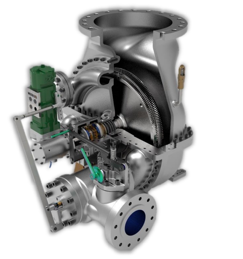
Steam turbines are mechanical devices that convert thermal energy from pressurized steam into rotational mechanical energy, which can then drive generators to produce electricity or power machinery like pumps and compressors. Invented in the late 19th century, they remain a cornerstone of power generation and industrial processes worldwide, prized for their efficiency, scalability, and adaptability to various heat sources—coal, nuclear, biomass, natural gas, or even solar thermal energy.
Basic Operating Principle
The steam turbine operates on the Rankine cycle, a thermodynamic process where heat transforms water into steam, which then expands to do work. Here’s how it unfolds:
- Heat Input: A heat source (e.g., burning fuel or nuclear fission) boils water in a boiler, creating high-pressure, high-temperature steam (typically 200-600°C, 10-300 bar).
- Expansion: This steam flows into the turbine, passing through blades mounted on a rotor. As it expands and loses pressure, it accelerates, pushing the blades and spinning the rotor.
- Work Output: The rotor’s rotation drives a connected shaft, powering a generator (for electricity) or other equipment.
- Exhaust: Spent steam exits—either to a condenser (cooling it back to water for reuse) or as usable heat (in CHP systems).
Efficiency depends on the steam’s initial conditions and the turbine’s design, typically ranging from 20% in small, simple units to over 45% in advanced power plants.
Types of Steam Turbines
Steam turbines vary widely based on design, pressure handling, and application. Here are the main categories:
- Impulse Turbines
- How They Work: Steam accelerates through stationary nozzles into high-velocity jets, striking curved blades (buckets) on the rotor. The pressure drop occurs entirely in the nozzles, not across the blades.
- Examples: The De Laval turbine (single-stage, high-speed) and Curtis turbine (velocity-compounded with multiple blade rows).
- Features: Simple, robust, and suited for high-pressure steam. Speeds can exceed 30,000 RPM in small units.
- Applications: Small-scale power generation, topping turbines in hybrid plants, or driving high-speed machinery.
- Reaction Turbines
- How They Work: Steam expands and accelerates through both fixed (stator) and moving (rotor) blades, dropping pressure gradually across each stage. The blades act like nozzles, creating a reactive force.
- Examples: The Parsons turbine, with dozens of stages for efficiency.
- Features: Complex, with airfoil-shaped blades and tight tolerances. Excels at lower pressures and high steam volumes.
- Applications: Large power plants (coal, nuclear, geothermal) needing maximum efficiency.
- Combination (Impulse-Reaction) Turbines
- How They Work: High-pressure stages use impulse designs, transitioning to reaction stages as pressure drops, optimizing energy extraction across the steam’s range.
- Features: Balances simplicity and efficiency, common in modern utility-scale turbines.
- Applications: Supercritical coal or combined-cycle gas plants.
- Condensing Turbines
- How They Work: Steam exhausts into a vacuum (0.03-0.1 bar) created by a condenser, maximizing pressure drop and energy output.
- Features: Large low-pressure (LP) blades handle high-volume steam. Requires cooling systems (water or air).
- Applications: Baseload power plants (e.g., 1,000 MW nuclear units).
- Back-Pressure Turbines
- How They Work: Steam exits at a higher pressure (e.g., 5-20 bar) for industrial use, rather than condensing.
- Features: Simpler, with dual power-and-heat output (CHP). Less efficient electrically but highly effective overall.
- Applications: Factories (e.g., paper mills) needing process steam.
- Extraction Turbines
- How They Work: Steam is tapped at intermediate stages for heating or processes, with the rest continuing to generate power.
- Features: Flexible, with control valves adjusting extraction flow.
- Applications: Refineries or district heating systems.
- Reheat Turbines
- How They Work: Steam exits the high-pressure (HP) stage, gets reheated in the boiler (e.g., to 540°C), then expands through intermediate-pressure (IP) and LP stages.
- Features: Boosts efficiency by 4-5% per reheat cycle. Complex, with extra piping.
- Applications: High-efficiency fossil-fuel plants.
- HP, IP, and LP Turbines
- How They Work: Segmented into sections on a single shaft, each optimized for its pressure range—small HP blades for high pressure, large LP blades for low pressure.
- Features: Modular, scalable, and standard in large plants.
- Applications: Gigawatt-scale power stations.
Historical Development
- Origins: Sir Charles Parsons invented the modern steam turbine in 1884, demonstrating a multi-stage reaction design that powered a ship’s lights. Gustaf de Laval’s 1880s impulse turbine complemented this, excelling at high speeds.
- Industrial Revolution: By 1900, turbines replaced steam engines in power generation, offering higher efficiency and scalability. Parsons’ designs scaled to megawatts within decades.
- 20th Century: Turbines evolved with metallurgy (e.g., chromium steels) and thermodynamics (e.g., reheat cycles), driving electrification worldwide.
Applications
- Power Generation: Over 80% of global electricity comes from steam turbines—coal (37%), nuclear (10%), gas (25%), and biomass/geothermal (small shares).
- Industrial: Drive compressors in chemical plants, pumps in refineries, or process steam in paper production.
- Marine Propulsion: Powered ships like the Titanic (29,000 hp) and warships until gas turbines took over post-WWII.
- Renewables: Biomass plants (e.g., wood-fired) and concentrated solar power use steam turbines for green energy.
Design and Materials
- Blades: HP blades (small, robust) use nickel-based superalloys (e.g., Inconel) for 600°C+ conditions. LP blades (large, lightweight) often use titanium to resist wet-steam erosion.
- Casings: Steel or alloy casings withstand pressure and thermal stress, with seals (labyrinth or brush) minimizing leaks.
- Rotor: Forged steel or alloy, balanced to handle 3,000-10,000 RPM and thermal expansion.
- Challenges: Creep (deformation at high heat), erosion (from wet steam), and fatigue (from cyclic loads) drive material innovation.
Efficiency and Performance
- Thermodynamic Limits: Ideal Rankine efficiency is ~60%, but real-world turbines hit 30-47%, depending on steam conditions (supercritical at 600°C, 300 bar pushes the upper end).
- Losses: Heat escapes via exhaust, friction, and leakage. Moisture in LP stages reduces output unless mitigated by superheating or separators.
- Enhancements: Reheat cycles, supercritical steam, and advanced blade profiles (via CFD) boost performance.
Modern Relevance
- Fossil Fuels: Coal and gas plants rely on steam turbines, though coal’s share declines with decarbonization.
- Nuclear: Essential for converting reactor heat to power, with massive LP turbines handling saturated steam.
- Renewables: Biomass (e.g., wood) and geothermal plants keep turbines relevant in green energy.
- Innovation: Ceramic blades (1,000°C tolerance), 3D-printed parts, and AI-driven controls push efficiency and durability.
Advantages and Limitations
- Advantages: High power output (up to 1,500 MW per unit), long lifespan (30-50 years), and fuel flexibility.
- Limitations: Complex infrastructure (boilers, condensers), slow startup (hours vs. minutes for gas turbines), and reliance on water for cooling.
Steam turbines are engineering marvels, blending physics, materials science, and ingenuity. From Parsons’ first 7.5 kW unit to today’s gigawatt giants, they’ve shaped our energy landscape and continue to adapt to a changing world. Whether driving a factory or lighting a city, their legacy endures.
Steam turbines are mechanical devices that transform the thermal energy stored in pressurized steam into rotational mechanical energy, which can then be used to generate electricity or power industrial equipment like pumps, compressors, or fans. They are a critical technology in modern energy production, found in power plants, factories, and even historical ships, and they operate by harnessing the expansion of steam to spin a rotor connected to a generator or machinery. Invented over a century ago, steam turbines remain vital due to their efficiency, reliability, and ability to work with diverse heat sources such as coal, natural gas, nuclear reactions, biomass like wood, or concentrated solar power. Below is a detailed exploration of how they work, their types, history, applications, design specifics, and their role today.
The basic principle behind a steam turbine is straightforward yet rooted in thermodynamics, specifically the Rankine cycle, which is a process that converts heat into work. Water is heated in a boiler using a fuel source, turning it into high-pressure steam at temperatures ranging from 200 to 600 degrees Celsius and pressures from 10 to 300 bar, depending on the system. This steam is then directed into the turbine, where it flows over a series of blades attached to a rotor. As the steam expands and loses pressure, it accelerates, pushing against the blades and causing the rotor to spin at speeds typically between 1,500 and 3,600 revolutions per minute, aligning with electrical grid frequencies of 50 or 60 Hz. The spinning rotor drives a shaft connected to a generator, producing electricity, or directly powers mechanical equipment. After passing through the turbine, the steam exits either into a condenser, where it cools back into water for reuse in a closed loop, or as usable heat for industrial processes in systems designed for combined heat and power.
Steam turbines come in several types, each designed for specific purposes based on how they handle steam and extract energy. Impulse turbines work by accelerating steam through stationary nozzles into high-speed jets that strike curved, bucket-shaped blades on the rotor. The pressure drop happens entirely in the nozzles, so the blades experience only kinetic energy transfer, not a pressure change. A famous example is the De Laval turbine, a single-stage design invented by Gustaf de Laval in the 1880s, capable of spinning at over 30,000 RPM, ideal for small, high-speed applications like pumps or early generators. Another impulse variant, the Curtis turbine, uses multiple rows of moving and stationary blades to compound velocity, reducing speed to a more manageable 3,000-6,000 RPM while extracting more energy, making it suitable for early power plants. Impulse turbines are simple, robust, and excel with high-pressure steam, but they lose efficiency at lower pressures or variable loads.
Reaction turbines, in contrast, extract energy through both pressure drop and steam expansion across the blades themselves. Steam passes through fixed stator blades that direct it onto moving rotor blades, where it accelerates and expands, creating a reactive force that drives the rotor. This design, pioneered by Sir Charles Parsons in 1884, typically features dozens of stages—alternating fixed and moving blades—to gradually extract energy, making it highly efficient for large-scale power generation. The blades are shaped like airfoils, requiring precise manufacturing to handle aerodynamic forces, and their size increases from high-pressure to low-pressure stages to accommodate expanding steam. Reaction turbines dominate in big power plants because they handle lower-pressure steam well and achieve efficiencies up to 90% of the theoretical maximum, though they’re more complex and costly than impulse designs.
Many modern turbines combine impulse and reaction principles to optimize performance across a wide pressure range. In these combination turbines, the high-pressure stages use an impulse design with nozzles and sturdy blades to manage initial conditions—say, 300 bar and 600°C—while later stages shift to reaction designs as the steam expands, improving efficiency in intermediate- and low-pressure zones. This hybrid approach is common in supercritical coal plants or combined-cycle gas plants, where steam conditions push material limits, and designers use computational fluid dynamics to fine-tune blade transitions, minimizing energy losses.
Condensing turbines are built to maximize power output by exhausting steam into a vacuum, typically 0.03 to 0.1 bar, created by a condenser cooled with water from rivers, oceans, or cooling towers, or sometimes air in dry regions. This low exhaust pressure allows the steam to expand further, extracting more energy. These turbines feature massive low-pressure blades—sometimes over 1.5 meters long—to handle the high-volume, low-density steam, often in dual-flow designs to split the exhaust and reduce axial thrust. They’re the backbone of large power plants, like a 1,200 MW nuclear unit, but require extensive cooling infrastructure, adding complexity and environmental considerations like water usage or thermal pollution.
Back-pressure turbines, on the other hand, exhaust steam at a higher pressure, such as 5 to 20 bar, so it can be used for industrial processes like heating, drying, or driving other equipment. Found in factories like paper mills or chemical plants, they sacrifice some electrical efficiency—since less energy is extracted as work—but excel in combined heat and power setups, where total energy efficiency can reach 80% or more when heat is factored in. They’re simpler than condensing turbines, lacking a condenser, and their exhaust pressure is tailored to downstream needs, making them economical for specific industries.
Extraction turbines offer flexibility by allowing steam to be tapped at intermediate stages for industrial use, while the rest continues through the turbine to generate power. For example, a refinery might extract steam at 15 bar for heating and 2 bar for feedwater preheating, with the remainder condensing for electricity. Control valves adjust the extraction flow, and the turbine’s design accounts for reduced steam volume in later stages, balancing power and process demands. These are common in facilities needing both electricity and variable steam supplies, like steel mills or district heating systems.
Reheat turbines improve efficiency by interrupting the expansion process. After passing through the high-pressure stage, steam—now at 20-50 bar—returns to the boiler to be reheated to its original temperature, say 540°C, before entering intermediate- and low-pressure stages. This increases the cycle’s average heat-addition temperature, boosting efficiency by 4-5% for a single reheat, or up to 7% with double reheat in ultra-efficient plants. Reheat designs are standard in large fossil-fuel plants, requiring extra piping and moisture separators to handle wetter steam in later stages, but the added complexity pays off in fuel savings.
In large power plants, turbines are often split into high-pressure, intermediate-pressure, and low-pressure sections, each optimized for its steam conditions and mounted on a single shaft. High-pressure turbines have small, robust blades to handle extreme conditions—up to 300 bar and 600°C—using materials like chromium-steel alloys to resist creep and corrosion. Intermediate-pressure turbines manage reheated steam at 20-50 bar, with mid-sized blades, while low-pressure turbines feature massive blades—up to 2 meters long—to process low-pressure, high-volume steam, often in twin-flow layouts. This segmentation is standard in gigawatt-scale plants, simplifying maintenance and maximizing efficiency.
The history of steam turbines begins in the late 19th century. Sir Charles Parsons built the first practical multi-stage reaction turbine in 1884, generating 7.5 kW to power a ship’s lights, proving the concept’s potential. Around the same time, Gustaf de Laval developed his impulse turbine, focusing on high-speed applications. By 1900, turbines outpaced reciprocating steam engines in power generation, offering higher efficiency and scalability. Early 20th-century advances in metallurgy—introducing heat-resistant steels—allowed turbines to handle higher temperatures and pressures, scaling to megawatts and driving the electrification of cities. During World War II, steam turbines powered massive ships like the Titanic, with 29,000 horsepower, and continued evolving with innovations like reheat cycles and supercritical steam in the mid-20th century.
Steam turbines have a vast range of applications. In power generation, they produce over 80% of the world’s electricity—37% from coal, 25% from gas in combined-cycle plants, 10% from nuclear, and smaller shares from biomass, geothermal, and solar thermal. Industrially, they drive compressors in chemical plants, pumps in oil refineries, and provide process steam in paper production. Historically, they propelled naval vessels and merchant ships until gas turbines took over post-war. Today, they’re key to renewable energy, powering biomass plants burning wood or agricultural waste, and concentrated solar power systems where mirrors heat a fluid to generate steam.
Design-wise, steam turbines are engineering marvels. Blades vary by stage—high-pressure blades are small, thick, and made of nickel-based superalloys like Inconel 718 to withstand 600°C and resist creep, while low-pressure blades are long, thin, and often titanium to combat erosion from wet steam droplets. Casings are forged steel or alloys, designed to contain high pressures and temperatures, with labyrinth or brush seals minimizing steam leakage around the rotor. The rotor itself, a massive steel forging, must be perfectly balanced to spin at thousands of RPM without vibration, expanding and contracting with heat. Challenges include creep deformation at high temperatures, blade erosion from moisture, and fatigue from years of cyclic loading, driving ongoing material research into ceramics and coatings.
Efficiency in steam turbines hinges on steam conditions and design. A basic system might convert 20-30% of heat into work, losing the rest to exhaust and friction. Advanced plants with supercritical steam—600°C, 300 bar—reach 45-47%, nearing the Rankine cycle’s ideal limit of around 60%. Losses come from heat escaping in the exhaust, turbulence in blade gaps, and moisture in low-pressure stages, which reduces energy output unless countered by superheating or moisture separators. Innovations like reheat cycles, where steam is reheated mid-process, and precise blade profiles designed with computational fluid dynamics, push performance higher.
Steam turbines remain critical today. In fossil-fuel plants, they’re the workhorse for coal and gas, though coal’s role shrinks with climate goals. Nuclear power relies on them to convert reactor heat into electricity, with huge low-pressure turbines handling saturated steam from boiling water reactors. In renewables, they power biomass plants—burning wood or waste—and geothermal facilities, while concentrated solar power uses them to turn sunlight into electricity. Modern advancements include ceramic blades tolerating 1,000°C, 3D-printed components for complex shapes, and AI-driven controls optimizing performance in real time, ensuring turbines stay relevant in a shifting energy landscape.
The advantages of steam turbines are numerous. They deliver massive power—up to 1,750 MW in nuclear units like the Arabelle turbine—run reliably for 30-50 years with maintenance, and adapt to any heat source, from fossil fuels to renewables. However, they’re not without drawbacks. They require complex infrastructure—boilers, condensers, cooling systems—take hours to start up compared to minutes for gas turbines, and need water for cooling, posing challenges in arid regions or with environmental regulations.
A standout example of their scale is the Arabelle turbine, used in French nuclear plants, producing 1,750 MW with low-pressure blades over 2 meters long, powering millions of homes. On a smaller scale, a wood-fired turbine might generate 5 kW for a cabin, burning a few kilograms of wood per hour. From these extremes, steam turbines showcase their versatility and enduring impact. Since Parsons’ first design, they’ve evolved from kilowatts to gigawatts, shaping how we generate power and likely to persist as we balance fossil fuels with sustainable energy.
Steam turbines are remarkable machines that have played a pivotal role in shaping the modern world by converting thermal energy from steam into mechanical work, primarily for generating electricity or driving industrial equipment. Their ability to harness the power of steam—produced by heating water with fuels like coal, gas, nuclear energy, biomass, or even solar heat—makes them one of the most versatile and widely used technologies in energy production. With a history stretching back to the late 19th century, steam turbines have evolved from simple experimental devices into highly efficient, complex systems that power everything from small workshops to entire cities. Let’s continue exploring their mechanics, variations, historical significance, technical details, applications, and their place in today’s energy landscape, diving deeper into each aspect.
The operation of a steam turbine is rooted in the Rankine cycle, a thermodynamic process that efficiently turns heat into usable energy. In a boiler, water is heated under pressure until it becomes steam, reaching temperatures between 200 and 600 degrees Celsius and pressures from 10 to 300 bar, depending on the system’s design and purpose. For example, a small biomass boiler might produce steam at 10 bar and 200°C, while a supercritical coal plant pushes conditions to 300 bar and 600°C for maximum efficiency. This high-pressure steam enters the turbine and flows over blades attached to a rotor—a large, cylindrical shaft. As the steam expands, its pressure and temperature drop, accelerating it into the blades and causing the rotor to spin. The rotor’s speed varies—1,500 RPM for 50 Hz grids, 3,600 RPM for 60 Hz, or even 30,000 RPM in high-speed impulse designs—driving a generator that converts the motion into electricity. After doing its work, the steam exits the turbine, either condensing into water in a closed-loop system or leaving as usable heat for industrial processes.
The blades are the heart of the turbine, and their interaction with steam defines the turbine’s type. In impulse turbines, steam passes through stationary nozzles that accelerate it into high-velocity jets—sometimes exceeding 500 meters per second—before striking curved, bucket-like blades on the rotor. The pressure drop occurs entirely in the nozzles, so the blades only convert kinetic energy into motion. Gustaf de Laval’s single-stage turbine, developed in the 1880s, is a classic impulse design, spinning at extreme speeds like 30,000 RPM to power small generators or pumps. Its simplicity made it a breakthrough, though its efficiency drops with larger steam volumes. The Curtis turbine, another impulse variant, adds velocity compounding—steam bounces between multiple rows of moving and stationary blades, extracting energy step-by-step, reducing speed to 3,000-6,000 RPM for practical use in early 20th-century power plants. Impulse turbines are rugged and ideal for high-pressure steam, but they struggle with lower-pressure conditions or fluctuating loads.
Reaction turbines take a different approach, extracting energy through continuous steam expansion across both fixed and moving blades. Fixed stator blades direct steam onto moving rotor blades, where it accelerates and drops in pressure, creating a reactive force—like a rocket’s thrust—that spins the rotor. Sir Charles Parsons pioneered this in 1884 with a multi-stage design, using dozens or even hundreds of stages to gradually extract energy. Each stage contributes a small pressure drop, with blade sizes growing from a few centimeters in high-pressure sections to over a meter in low-pressure ones, matching the steam’s expansion. The blades are airfoil-shaped, precision-crafted to minimize turbulence, and require tight tolerances—gaps as small as a millimeter—to prevent steam leakage. Reaction turbines shine in large power plants, achieving efficiencies up to 90% of the ideal Rankine cycle, but their complexity and cost make them less practical for small-scale use.
Combination turbines blend these principles for versatility. In the high-pressure stages, an impulse design handles the intense initial conditions—say, 300 bar and 600°C—with nozzles and sturdy blades, while later stages shift to reaction designs as the steam expands to 20 bar or less, optimizing energy extraction across the pressure spectrum. This hybrid setup is common in modern supercritical plants, where steam pushes material limits. Designers use computational tools to smooth the transition, ensuring minimal shock losses as steam behavior changes, making these turbines efficient and compact for utility-scale power generation.
Condensing turbines focus on maximizing power by exhausting steam into a vacuum, typically 0.03 to 0.1 bar, created by a condenser. This low pressure lets the steam expand further, extracting nearly all its energy. The low-pressure stages feature enormous blades—sometimes 1.5 to 2 meters long—spinning at tip speeds near 500 m/s, often in dual-flow configurations where steam splits to opposite sides of the turbine to balance thrust. Condensers use water from rivers or cooling towers, evaporating 1-2% of a plant’s output as waste heat, or air in water-scarce areas, though air-cooling reduces efficiency. These turbines power massive plants—coal, nuclear, or gas-fired—delivering hundreds of megawatts, but they need extensive cooling systems, raising costs and environmental concerns like thermal discharge into waterways.
Back-pressure turbines prioritize dual outputs, exhausting steam at 5 to 20 bar for industrial use—think heating pulp in a paper mill or driving a chemical reactor—rather than condensing it. The turbine’s final stage is tuned to this pressure, with fewer blades than a condensing design, and the exhaust steam retains significant heat, boosting total energy efficiency to 80% or more in combined heat and power systems. They’re simpler, skipping the condenser, and cost-effective where heat is as valuable as power, though their electrical efficiency is lower since less steam energy becomes work.
Extraction turbines add flexibility, tapping steam at intermediate points—say, 15 bar for process heat and 2 bar for boiler feedwater heating—while the rest generates power. Control valves regulate extraction, and the turbine’s staging adjusts for reduced flow in later sections, requiring sophisticated engineering to balance outputs. These are ideal for refineries or district heating, where steam demands shift, offering adaptability at the cost of added complexity.
Reheat turbines enhance efficiency by reheating steam mid-process. After the high-pressure stage drops steam to 20-50 bar, it returns to the boiler, reheating to 540-600°C, then expands through intermediate- and low-pressure stages. This raises the cycle’s average temperature, lifting efficiency by 4-5% for one reheat or 7% for two, though double-reheat adds cost and rarely justifies itself outside ultra-efficient plants. Reheat systems need extra piping and moisture separators—wet steam after reheating erodes blades—making them standard in large fossil-fuel stations chasing every percentage point of fuel savings.
Large turbines often split into high-pressure, intermediate-pressure, and low-pressure sections on one shaft, each tailored to its steam range. High-pressure turbines use small, thick blades—10-20 cm long—to handle 300 bar and 600°C, made of nickel alloys like Inconel to resist creep and corrosion. Intermediate-pressure turbines, with mid-sized blades, manage reheated steam at 20-50 bar, while low-pressure turbines have huge blades—up to 2 meters—to process low-pressure, high-volume steam, often splitting flow to twin exhausts. This modular design dominates gigawatt-scale plants, simplifying repairs and optimizing performance across the steam’s journey.
Historically, steam turbines emerged during the Second Industrial Revolution. Parsons’ 1884 reaction turbine, generating 7.5 kW, powered a ship’s lights, proving multi-stage efficiency. De Laval’s impulse design, from the same era, targeted high-speed niches. By 1900, turbines outpaced steam engines, scaling to megawatts with better steels and boiler tech. The 20th century saw them power ships—the Titanic’s 29,000 hp turbines drove it across the Atlantic—and electrify nations, with innovations like reheat cycles (1930s) and supercritical steam (1950s) pushing efficiency from 20% to over 45%.
Applications span industries. In power generation, steam turbines produce over 80% of global electricity—37% from coal, 25% from gas, 10% from nuclear, plus biomass, geothermal, and solar thermal. Industrially, they run compressors in chemical plants, pumps in oil fields, and supply steam in paper mills. They once dominated marine propulsion, powering warships and liners until gas turbines took over post-1940s. Today, they’re key to renewables—biomass plants burn wood or waste, while solar thermal systems use mirrors to heat steam—bridging fossil and green energy.
Design details reveal their complexity. High-pressure blades, small and robust, use superalloys like Inconel 718 or Rene 41, tolerating 600°C for decades, with chromium coatings fighting corrosion. Low-pressure blades, long and thin, use titanium to resist wet-steam erosion, with tips moving at supersonic speeds. Casings, forged from steel or alloys, contain pressures up to 300 bar, with labyrinth seals—layered grooves—cutting leakage. Rotors, weighing tons, are precision-balanced to spin at 3,000 RPM without vibration, expanding inches from heat. Challenges include creep (slow deformation at high heat), erosion (wet steam pitting blades), and fatigue (cracks from cyclic stress), driving research into ceramics, which handle 1,000°C, and protective coatings.
Efficiency varies widely. Small turbines hit 20-30%, losing heat to exhaust and friction. Advanced plants with supercritical steam—600°C, 300 bar—reach 45-47%, nearing the Rankine ideal of 60%. Losses stem from exhaust heat, blade-gap leaks, and moisture in low-pressure stages, which drops output unless mitigated by superheating to 540°C or separators removing water droplets. Reheat cycles, supercritical conditions, and CFD-optimized blades—curved for minimal turbulence—push performance, with top plants achieving over 90% of theoretical efficiency.
Today, steam turbines remain vital. Fossil-fuel plants—coal and gas—rely on them, though coal declines with emissions goals. Nuclear plants use them to turn reactor heat into power, with massive low-pressure turbines handling saturated steam at 70 bar. Renewables lean on them—biomass burns wood for 1-50 MW, geothermal taps underground steam, and solar thermal generates steam from sunlight. Innovations keep them competitive: ceramic blades for higher heat, 3D-printed parts for precision, and AI controls for real-time optimization, ensuring they adapt to a decarbonizing world.
Their strengths are clear—massive output (1,750 MW in nuclear units), longevity (30-50 years), and fuel flexibility. But they’re not perfect—complex setups with boilers and condensers, slow startups (hours vs. minutes for gas turbines), and water-heavy cooling limit them in dry areas or fast-response grids. The Arabelle turbine, at 1,750 MW, powers 2 million homes with 2-meter blades, while a 5 kW wood-fired unit lights a cabin—proof of their range. From Parsons’ 7.5 kW to today’s giants, steam turbines have electrified the world and will evolve as we balance legacy fuels with sustainability.
Industrial Steam Turbine
Industrial steam turbines are a specialized subset of steam turbines designed specifically for use in industrial settings, where they generate electricity, drive machinery, or provide process steam for manufacturing and production processes. Unlike utility-scale turbines found in large power plants, which focus on maximizing electrical output for the grid, industrial steam turbines are tailored to meet the unique energy demands of factories, refineries, chemical plants, and other industrial facilities. They prioritize flexibility, efficiency in combined heat and power (CHP) applications, and integration with industrial processes, often operating at smaller scales—ranging from a few kilowatts to tens of megawatts—while still leveraging the same fundamental principles as their larger counterparts. Below is a detailed exploration of industrial steam turbines, covering their mechanics, types, applications, design features, and significance in modern industry.
Industrial steam turbines work by converting thermal energy from steam into mechanical energy, typically within the framework of the Rankine cycle. Steam is produced in a boiler heated by fuels like natural gas, coal, biomass (such as wood or agricultural waste), oil, or waste heat from industrial processes. The steam, pressurized to between 5 and 100 bar and heated to 200-540°C, enters the turbine and expands across a series of blades mounted on a rotor. This expansion drives the rotor, spinning it at speeds like 3,000 RPM (for 50 Hz systems) or 3,600 RPM (60 Hz), which then powers a generator for electricity or directly drives equipment such as pumps, compressors, or fans. The steam’s exit path depends on the turbine’s purpose—some exhaust into a condenser for maximum power, while others release steam at usable pressures (e.g., 2-20 bar) for heating or process use, a hallmark of industrial applications.
The types of industrial steam turbines reflect their adaptability to factory needs. Back-pressure turbines are common, exhausting steam at a higher pressure—say, 5-20 bar—rather than condensing it, so the exhaust can heat buildings, dry materials, or power downstream processes. For example, in a paper mill, a back-pressure turbine might generate 5 MW of electricity while supplying 10 tons/hour of 10-bar steam to dry pulp, achieving total energy efficiency above 80% when heat is included, though electrical efficiency alone might be 20-30%. Extraction turbines offer more versatility, allowing steam to be tapped at intermediate stages—perhaps 15 bar for a chemical reactor and 3 bar for preheating—while the rest generates power. These turbines use control valves to adjust extraction flow, balancing electricity and steam output, making them ideal for refineries or food processing plants with variable demands.
Condensing turbines, though less frequent in industrial settings, are used when electricity is the primary goal. They exhaust steam into a vacuum (0.05-0.1 bar) via a condenser, maximizing energy extraction with efficiencies up to 35-40%. A small factory might use a 1 MW condensing turbine to power its grid, condensing steam with a water-cooled system tied to a cooling tower. Combination turbines, blending impulse and reaction designs, also appear in larger industrial setups—impulse stages handle high-pressure steam (e.g., 50 bar), transitioning to reaction stages for lower pressures, optimizing performance in plants with diverse steam conditions. Single-stage turbines, simple and compact, suit small applications like a 50 kW unit driving a pump, while multi-stage designs dominate in bigger systems needing higher efficiency, such as a 10 MW turbine in a steel mill.
Applications of industrial steam turbines are vast and tied to specific industries. In chemical plants, they generate power (e.g., 2-20 MW) while supplying steam for reactions or distillation, often using extraction turbines to match process needs. Pulp and paper mills rely on back-pressure turbines, producing 5-15 MW of electricity and steam at 5-10 bar to dry paper, leveraging wood waste as fuel for sustainability. Oil refineries use extraction or condensing turbines, delivering 10-50 MW and steam for cracking or heating, often fueled by refinery byproducts. Sugar mills burn bagasse (cane waste) to power turbines—typically 1-5 MW—while heating juice evaporators. Textile factories use small turbines (100 kW-1 MW) for power and steam dyeing, and food processing plants like breweries employ CHP turbines for electricity and sterilization heat. Mining operations drive compressors or pumps with turbines, often in remote areas using diesel or biomass.
Design features of industrial steam turbines reflect their practical demands. They’re typically smaller than utility turbines—ranging from 50 kW to 50 MW—making them compact enough to fit within factory footprints. Blades vary by stage: high-pressure blades, 5-20 cm long, use nickel alloys like Inconel to handle 540°C and 100 bar, resisting creep and corrosion, while low-pressure blades, up to 1 meter, might use stainless steel or titanium for durability against wet steam. Rotors, forged from steel, spin at 3,000-10,000 RPM, balanced to minimize vibration, with couplings or gearboxes linking to machinery. Casings, made of cast steel, withstand pressures up to 100 bar, with seals like labyrinth designs reducing steam leaks. Boilers are often integrated, sized for 1-100 tons/hour of steam, and fuel flexibility—natural gas, biomass, or waste heat—lets them adapt to local resources. Control systems, increasingly digital, adjust steam flow and extraction in real time, optimizing for shifting loads.
Efficiency in industrial steam turbines depends on their role. Electrical efficiency ranges from 20-40%, lower than utility turbines (45%+), due to smaller scale and heat-focused designs. However, in CHP setups, total efficiency—power plus usable heat—can hit 70-85%, far surpassing condensing-only systems. For instance, a 5 MW back-pressure turbine might convert 25% of fuel energy to electricity and 50% to process steam, losing only 25% to waste heat. Losses come from exhaust heat, friction, and blade-gap leaks, mitigated by superheating steam to 540°C or using moisture separators to dry low-pressure steam. Multi-stage designs with 5-20 stages extract energy gradually, boosting efficiency over single-stage units, though at higher cost.
Historically, industrial steam turbines evolved alongside the Industrial Revolution. Early 20th-century factories used steam engines, but by the 1910s, turbines—building on Parsons’ and De Laval’s work—offered better efficiency and power density. World War II saw them power factories and ships, often fueled by coal or oil. Post-war, they adapted to industrial CHP, with the 1970s energy crisis spurring biomass and waste-heat use. Today, they’re modernizing with automation and sustainable fuels, reflecting industry’s push for efficiency and lower emissions.
Their significance in modern industry is profound. They provide on-site power, reducing grid reliance and costs—critical in remote or unstable regions. CHP capability slashes energy bills; a 10 MW turbine might save a factory $1-2 million yearly by reusing steam. Fuel flexibility supports sustainability—biomass turbines burn wood chips or sawdust, cutting fossil fuel use, while waste-heat recovery harnesses exhaust from furnaces or engines. In a steel plant, a 20 MW turbine might use blast furnace gas, generating power and steam without extra fuel. Reliability is key—turbines run 20-30 years with maintenance, handling 24/7 loads in harsh conditions.
Challenges exist. Initial costs are high—a 5 MW system might run $2-5 million, including boiler and installation—though payback comes in 3-7 years with CHP savings. Maintenance involves blade inspections, seal replacements, and boiler cleaning, costing $50,000-$100,000 yearly for a mid-sized unit. Emissions—CO2, particulates—require scrubbers or filters to meet regulations, especially with biomass or coal. Space needs—boilers, turbines, condensers—limit use in cramped facilities, and startup times (30 minutes to hours) lag behind gas turbines’ responsiveness.
Examples highlight their range. A 2 MW extraction turbine in a chemical plant burns natural gas, producing 1.5 MW electricity and 5 tons/hour of 10-bar steam for reactors, with a $1 million setup cost offset by $300,000 annual savings. A 500 kW back-pressure turbine in a sawmill uses wood waste, powering tools and drying lumber, costing $200,000 but paying back in two years. A 10 MW condensing turbine in a refinery, fueled by oil residues, runs at 35% efficiency, powering pumps and compressors with a water-cooled condenser.
Industrial steam turbines bridge power and process needs, offering tailored solutions where utility turbines don’t fit. Their adaptability—handling diverse fuels, scales, and outputs—keeps them vital in manufacturing, from small workshops to sprawling plants. As industries chase efficiency and sustainability, these turbines evolve with smarter controls, tougher materials, and greener fuels, ensuring they remain a workhorse of industrial energy.
Industrial steam turbines are robust, versatile machines engineered to meet the specific energy demands of industrial facilities, converting steam’s thermal energy into mechanical work for electricity generation, machinery operation, or process steam supply. Unlike their utility-scale counterparts focused on massive grid power, industrial steam turbines are designed for flexibility, often prioritizing combined heat and power (CHP) efficiency and integration with manufacturing processes. Found in factories, refineries, and mills, they range from compact units producing a few kilowatts to larger systems delivering tens of megawatts, balancing power needs with industrial heat requirements. Let’s delve deeper into their mechanics, types, applications, design intricacies, historical context, modern role, and operational details, expanding on their significance in industry.
The core operation of an industrial steam turbine follows the Rankine cycle, a thermodynamic process tailored to industrial settings. A boiler generates steam by burning fuels like natural gas, coal, oil, biomass (e.g., wood chips, bagasse), or capturing waste heat from processes like furnace exhausts. Steam conditions vary—small systems might produce 5-20 bar at 200-300°C, while larger ones reach 50-100 bar at 500-540°C, depending on efficiency goals and fuel quality. This steam enters the turbine, flowing over blades fixed to a rotor. As it expands, its pressure drops—say, from 50 bar to 5 bar—accelerating across the blades and spinning the rotor at speeds like 3,000 RPM (50 Hz grids), 3,600 RPM (60 Hz), or higher (up to 10,000 RPM) in smaller, high-speed units. The rotor drives a generator for electricity or directly powers equipment—pumps, fans, compressors—via a shaft or gearbox. Exiting steam either condenses in a vacuum (0.05-0.1 bar) for maximum power or leaves at usable pressures (2-20 bar) for heating, drying, or chemical reactions, a key feature in industrial CHP systems.
Types of industrial steam turbines are defined by their steam handling and output priorities. Back-pressure turbines exhaust steam at elevated pressures—typically 5-20 bar—rather than condensing it, supplying heat for industrial tasks. In a textile plant, a 3 MW back-pressure turbine might burn biomass, generating 2.5 MW of electricity while providing 8 tons/hour of 10-bar steam to dye fabrics, achieving 75-85% total efficiency by reusing heat, though electrical efficiency stays at 20-30%. Extraction turbines add control, tapping steam at multiple stages—e.g., 15 bar for a distillation column, 3 bar for boiler feedwater heating—while the rest powers the rotor. A 10 MW extraction turbine in a refinery could produce 8 MW and extract 20 tons/hour of steam at two pressures, using valves to adjust flow based on demand, ideal for fluctuating process needs. Condensing turbines, less common industrially, focus on power, exhausting into a condenser’s vacuum to hit 35-40% electrical efficiency. A 5 MW condensing turbine in a mining operation might power compressors, using a water-cooled condenser tied to a nearby stream.
Combination turbines, mixing impulse and reaction designs, suit larger industrial systems. High-pressure stages (e.g., 50 bar) use impulse blades—steam jets from nozzles onto buckets—while lower-pressure stages (e.g., 10 bar) shift to reaction blades, where steam expands across moving blades for efficiency. A 15 MW combination turbine in a chemical plant might handle 540°C steam, optimizing energy extraction across stages. Single-stage turbines, with one blade set, are compact and simple—think a 100 kW unit driving a pump in a small factory—while multi-stage turbines, with 5-20 stages, boost efficiency in bigger setups like a 20 MW sugar mill turbine. Reheat turbines, rare industrially due to cost, reheat steam mid-process (e.g., from 20 bar back to 540°C), lifting efficiency by 4-5%, used in high-output plants like steelworks needing every edge.
Applications tie directly to industrial sectors. Chemical plants use 2-20 MW turbines for power and steam—e.g., a 5 MW extraction unit supplies 10-bar steam for reactors while running agitators. Pulp and paper mills favor back-pressure turbines—say, a 10 MW unit burning wood waste, producing 8 MW and 15 tons/hour of 5-bar steam to dry paper. Oil refineries deploy 10-50 MW turbines, often extraction or condensing, using byproduct fuels like petroleum coke to power pumps and supply steam for cracking. Sugar mills burn bagasse for 1-5 MW turbines, driving mills and heating evaporators—e.g., a 3 MW unit processes 500 tons of cane daily. Textile plants use 100 kW-1 MW turbines for power and steam dyeing, while food processors like dairies run 500 kW-2 MW CHP turbines for sterilization and electricity. Mining sites power compressors or hoists with 1-10 MW turbines, often in remote areas using diesel or local biomass.
Design specifics reflect industrial practicality. Sizes range from 50 kW to 50 MW—smaller than utility turbines (100 MW+)—fitting tight factory spaces. High-pressure blades, 5-20 cm long, use nickel-based superalloys (e.g., Inconel 718) to handle 540°C and 100 bar, resisting creep and oxidation, often coated with chromium carbide for durability. Low-pressure blades, up to 1 meter, use stainless steel or titanium to combat wet-steam erosion, with tips moving at 300-500 m/s. Rotors, forged from high-strength steel, weigh tons yet spin precisely, balanced to avoid vibration, with couplings or gearboxes (e.g., reducing 10,000 RPM to 1,500 RPM) linking to loads. Casings, cast steel or alloys, contain pressures up to 100 bar, with labyrinth seals—concentric grooves—cutting leakage by 5-10%. Boilers, producing 1-100 tons/hour of steam, integrate with turbines, burning diverse fuels—natural gas (clean, efficient), biomass (sustainable), or waste heat (free energy). Digital controls monitor steam flow, pressure, and extraction, adjusting in seconds for optimal output.
Efficiency balances power and heat. Electrical efficiency spans 20-40%—a 5 MW condensing turbine might hit 35%, converting 35% of fuel energy to power, losing 65% to exhaust and friction. CHP systems shine, with back-pressure or extraction turbines reaching 70-85% total efficiency—e.g., a 3 MW unit turns 25% into electricity, 50% into usable steam, losing 25% to waste. Losses stem from exhaust heat, blade turbulence, and moisture—wet steam in low-pressure stages cuts output by 5-10% unless superheated to 540°C or dried with separators. Multi-stage designs extract energy gradually—5-20 stages vs. 1—lifting efficiency by 10-15% over single-stage units, though complexity rises. Fuel quality matters—dry biomass (4.5 kWh/kg) outperforms wet wood (3 kWh/kg), reducing steam output if moisture exceeds 20%.
Historically, industrial steam turbines grew from late 19th-century innovations. Parsons’ 1884 reaction turbine and De Laval’s impulse design laid the groundwork, but by the 1910s, factories adopted turbines over steam engines for higher efficiency—10-20% vs. 5-10%. Early 20th-century mills used coal-fired turbines for power and heat, scaling to megawatts by the 1930s. WWII spurred industrial use—turbines ran factories on coal or oil when grids faltered. The 1970s energy crisis boosted CHP and biomass turbines, cutting costs as oil prices soared. Today, they align with sustainability—waste-heat turbines in steelworks or biomass units in sawmills reflect greener priorities.
Their modern role is critical. On-site power cuts grid dependence—a 5 MW turbine saves a factory $500,000-$1 million yearly vs. utility rates. CHP slashes energy costs—a 10 MW unit might recover $2 million annually in heat value. Sustainability drives adoption—biomass turbines burn wood waste (1-2 tons/hour for 5 MW), reducing fossil fuel use, while waste-heat units harness kiln exhaust, needing no extra fuel. Reliability stands out—turbines run 20-30 years, handling 8,000 hours/year in harsh conditions like dusty mines or humid mills. A 15 MW turbine in a petrochemical plant might use flare gas, producing power and steam without added emissions.
Challenges persist. Costs are steep—a 5 MW system with boiler and piping runs $2-5 million, though CHP payback hits 3-5 years. Maintenance—blade checks, seal swaps, boiler descaling—costs $50,000-$150,000 yearly, with downtime cutting output. Emissions require controls—biomass emits 50-200 mg/m³ of particulates, needing $100,000 scrubbers for compliance (e.g., U.S. EPA limits at 25 mg/m³). Space demands—10×20 meters for a 5 MW setup—clash with cramped plants, and startups take 30-60 minutes, lagging gas turbines’ 5-10 minutes. Fuel supply matters—wet biomass or inconsistent waste heat drops performance.
Examples illustrate their impact. A 1 MW back-pressure turbine in a dairy burns gas, producing 800 kW and 3 tons/hour of 5-bar steam for pasteurization, costing $500,000 but saving $150,000 yearly. A 20 MW extraction turbine in a steel mill uses blast furnace gas, delivering 15 MW and 30 tons/hour of 15-bar steam for rolling, with a $10 million cost offset by $3 million annual savings. A 200 kW condensing turbine in a remote mine, diesel-fueled, powers drills at 35% efficiency, costing $100,000 but cutting generator fuel by 50%.
Industrial steam turbines are industrial energy’s unsung heroes, blending power and heat with unmatched flexibility. Their evolution—from coal-fired mills to biomass-driven plants—mirrors industry’s shift to efficiency and sustainability. With smart controls, tough materials, and green fuels, they’ll keep factories humming, proving their worth in a changing world.
Industrial steam turbines are highly specialized machines engineered to meet the diverse energy needs of industrial environments, transforming the thermal energy of steam into mechanical work to generate electricity, power machinery, or supply process steam for manufacturing. Unlike utility-scale turbines that dominate large power plants with outputs in the hundreds of megawatts, industrial steam turbines are typically smaller—ranging from tens of kilowatts to 50 megawatts—and are designed for flexibility, often prioritizing combined heat and power (CHP) efficiency over raw electrical output. They serve as critical assets in factories, refineries, mills, and mines, integrating seamlessly with industrial processes to provide on-site power and heat. Let’s expand further on their mechanics, types, applications, design details, historical evolution, modern significance, and operational nuances, diving deeper into their role in industry.
The operation of an industrial steam turbine is based on the Rankine cycle, adapted to industrial demands. Steam is generated in a boiler using fuels such as natural gas, coal, oil, biomass like wood chips or bagasse, or waste heat from industrial processes—think exhaust from a cement kiln or refinery flare gas. Steam conditions vary widely: a small system might produce 5-20 bar at 200-300°C, suitable for a food processing plant, while a larger one reaches 50-100 bar at 500-540°C, common in chemical manufacturing. This steam enters the turbine, flowing over blades attached to a rotor—a heavy steel shaft. As it expands—dropping from, say, 50 bar to 5 bar—it accelerates, pushing the blades and spinning the rotor at speeds like 3,000 RPM for 50 Hz electrical grids, 3,600 RPM for 60 Hz, or up to 10,000 RPM in high-speed industrial units. The rotor’s motion drives a generator for electricity or directly powers equipment—pumps, compressors, fans—via a shaft, often with a gearbox to match equipment speeds. Exiting steam either condenses into a vacuum (0.05-0.1 bar) for maximum power or leaves at usable pressures (2-20 bar) for heating or process use, a defining trait of industrial turbines in CHP setups.
Types of industrial steam turbines are tailored to specific industrial roles. Back-pressure turbines exhaust steam at higher pressures—typically 5-20 bar—rather than condensing it, supplying heat for tasks like drying lumber or heating chemical vats. A 5 MW back-pressure turbine in a paper mill might burn wood waste, producing 4 MW of electricity and 10 tons/hour of 10-bar steam, hitting 80% total efficiency by reusing heat, though electrical efficiency is 25-30%. Extraction turbines provide more control, tapping steam at multiple points—e.g., 15 bar for a distillation tower, 3 bar for preheating boiler water—while the rest generates power. A 10 MW extraction turbine in a petrochemical plant could deliver 7 MW and 15 tons/hour of steam at two pressures, using automated valves to adjust flow, perfect for variable process demands. Condensing turbines, less common in industry, exhaust into a condenser’s vacuum, maximizing power at 35-40% efficiency. A 3 MW condensing turbine in a mining camp might power lighting and drills, using a water-cooled condenser tied to a local river.
Combination turbines mix impulse and reaction designs for larger systems. High-pressure stages (e.g., 50 bar, 540°C) use impulse blades—steam jets from nozzles onto buckets—while lower-pressure stages (e.g., 10 bar) shift to reaction blades, where steam expands across moving blades, boosting efficiency. A 20 MW combination turbine in a steel mill might optimize steam from blast furnace gas across 10 stages. Single-stage turbines, with one blade set, are simple and compact—say, a 200 kW unit driving a fan—while multi-stage turbines, with 5-20 stages, enhance efficiency in bigger setups like a 15 MW refinery turbine. Reheat turbines, though rare industrially, reheat steam mid-process—e.g., from 20 bar back to 540°C—adding 4-5% efficiency, used in high-value plants like fertilizer production needing top performance.
Applications span key industries. Chemical plants use 2-20 MW turbines for power and steam—e.g., a 5 MW extraction unit supplies 12-bar steam for reactors while running pumps. Pulp and paper mills rely on back-pressure turbines—say, a 10 MW unit burning sawdust, producing 8 MW and 20 tons/hour of 5-bar steam to dry pulp. Oil refineries deploy 10-50 MW turbines, often extraction or condensing, using byproduct fuels like heavy oil to power compressors and supply steam for cracking. Sugar mills burn bagasse for 1-5 MW turbines—e.g., a 2 MW unit processes 400 tons of cane daily, heating evaporators. Textile plants use 100 kW-1 MW turbines for power and steam dyeing, while food processors like breweries run 500 kW-2 MW CHP turbines for bottling and sterilization. Mining operations power hoists or ventilation with 1-10 MW turbines, often in remote sites using diesel or local wood.
Design details highlight their industrial focus. Sizes range from 50 kW to 50 MW, compact enough for factory floors—e.g., a 5 MW unit fits in a 10×20-meter space. High-pressure blades, 5-20 cm long, use nickel alloys like Inconel 718 or Hastelloy, handling 540°C and 100 bar, resisting creep and oxidation, often coated with ceramic or chromium for longevity. Low-pressure blades, up to 1 meter, use stainless steel or titanium, with tips at 300-500 m/s resisting wet-steam erosion. Rotors, forged from high-strength steel, weigh 1-10 tons, balanced to spin at 3,000-10,000 RPM, with couplings or gearboxes (e.g., 5:1 ratio) matching equipment speeds. Casings, cast steel or alloys, contain 100 bar, with labyrinth seals reducing leakage by 5-10%. Boilers, producing 1-100 tons/hour, integrate tightly—natural gas offers clean burns, biomass leverages waste, waste heat taps free energy. Digital controls—PLCs or SCADA—monitor pressure, temperature, and flow, adjusting in milliseconds for load shifts.
Efficiency balances electrical and thermal output. Electrical efficiency ranges from 20-40%—a 5 MW condensing turbine hits 35%, losing 65% to exhaust and friction, while CHP systems like back-pressure turbines reach 70-85% total efficiency. A 3 MW unit might convert 25% to power, 50% to 10-bar steam, losing 25% to waste. Losses include exhaust heat, blade turbulence, and moisture—wet steam cuts output by 5-10% unless superheated to 540°C or dried with separators. Multi-stage designs—5-20 stages—lift efficiency by 10-15% over single-stage, though costs rise. Fuel impacts performance—dry biomass (4.5 kWh/kg) beats wet (3 kWh/kg), with moisture above 20% slashing steam quality.
Historically, industrial steam turbines emerged from late 19th-century breakthroughs. Parsons’ 1884 reaction turbine and De Laval’s impulse design set the stage, but by the 1910s, factories swapped steam engines for turbines—10-20% efficiency vs. 5-10%. Early 20th-century coal-fired turbines powered mills, scaling to megawatts by the 1930s. WWII saw turbines run factories on oil or coal when grids failed. The 1970s energy crisis drove CHP adoption—biomass and waste-heat turbines cut oil reliance. Today, they align with green goals—wood-fired turbines in sawmills or waste-heat units in glassworks reduce carbon footprints.
Their modern significance is multifaceted. On-site power slashes costs—a 5 MW turbine saves $500,000-$1 million yearly vs. grid power. CHP doubles value—a 10 MW unit recovers $2-3 million in heat annually. Sustainability shines—biomass turbines burn 1-2 tons/hour of waste for 5 MW, while waste-heat units use kiln exhaust, needing no fuel. Reliability is unmatched—turbines run 20-30 years, 8,000 hours/year, in dust, heat, or humidity. A 15 MW turbine in a fertilizer plant might use ammonia process heat, producing power and steam emissions-free.
Challenges remain. Costs hit $2-5 million for a 5 MW system—boiler, turbine, piping—though CHP payback is 3-5 years. Maintenance—blade checks, seal swaps, boiler cleaning—runs $50,000-$150,000 yearly, with 1-2 days downtime. Emissions need controls—biomass emits 50-200 mg/m³ particulates, requiring $100,000 filters for compliance (e.g., EU limits at 20 mg/m³). Space—10×20 meters for 5 MW—strains tight plants, and startups (30-60 minutes) lag gas turbines (5-10 minutes). Fuel logistics—wet biomass or uneven waste heat—cut output if inconsistent.
Examples show their range. A 1 MW back-pressure turbine in a dairy burns gas, producing 800 kW and 3 tons/hour of 5-bar steam for pasteurization, costing $500,000 but saving $150,000 yearly. A 20 MW extraction turbine in a steel mill uses furnace gas, delivering 15 MW and 30 tons/hour of 15-bar steam, costing $10 million but saving $3 million annually. A 200 kW condensing turbine in a remote mine, diesel-fueled, powers drills at 35% efficiency, costing $100,000 but halving fuel use.
Industrial steam turbines are industrial energy’s backbone, merging power and heat with precision. Their evolution—from coal-fired mills to biomass-driven plants—tracks industry’s efficiency and sustainability push. With smart tech, durable materials, and green fuels, they’ll keep driving production, proving their enduring value.
Steam Turbine Generator
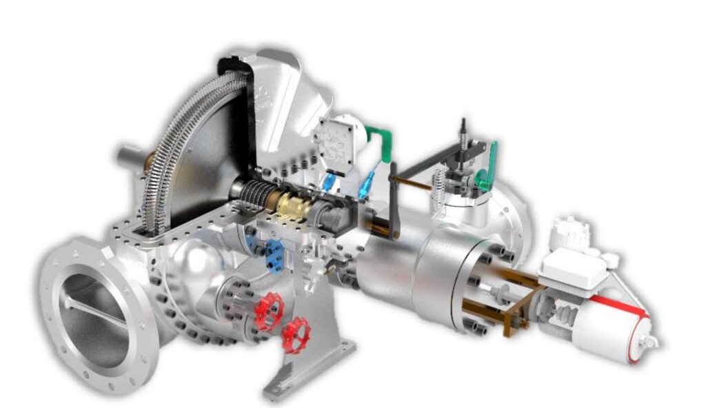
It seems like you’re asking for a detailed exploration of steam turbine generators, which are systems where a steam turbine is paired with an electric generator to produce electricity. Given our prior discussions, I’ll assume you want a general, informative overview of steam turbine generators, building on the foundation of steam turbines but focusing on their role in power generation, particularly in industrial and utility contexts. I’ll cover their mechanics, types, applications, design specifics, historical development, and modern significance, providing a comprehensive picture without tying it strictly to previous topics unless relevant. Here’s an in-depth look at steam turbine generators.
Steam turbine generators are integrated systems that convert thermal energy from steam into electrical energy, combining a steam turbine’s mechanical power with a generator’s ability to produce electricity. They are a cornerstone of modern power generation, used in industrial plants, utility-scale power stations, and even smaller off-grid setups, harnessing heat from fuels like coal, natural gas, nuclear reactions, biomass, or solar thermal sources. The steam turbine spins a rotor, which drives the generator to produce electricity, typically synchronized with electrical grids at 50 Hz (3,000 RPM) or 60 Hz (3,600 RPM). These systems range from small units generating a few kilowatts to massive installations producing over 1,000 megawatts, making them vital to both industrial self-sufficiency and global energy supply.
The mechanics of a steam turbine generator begin with the Rankine cycle. A boiler heats water using a heat source—say, burning coal at 1,200°C or nuclear fission at 300°C—producing high-pressure steam at 10-300 bar and 200-600°C, depending on the system. This steam enters the turbine, flowing over blades on a rotor. As it expands—dropping from, say, 100 bar to 0.05 bar—it accelerates, pushing the blades and spinning the rotor at speeds like 3,000-10,000 RPM. The rotor connects to a generator via a shaft, often with a gearbox in smaller units to adjust speed. Inside the generator, the rotor’s motion—surrounded by a stator with copper windings—induces an electromagnetic field, generating alternating current (AC) electricity. Steam exits either into a condenser (cooling it back to water for reuse) or at a usable pressure for industrial processes in CHP setups, with the condenser path maximizing electrical output.
Types of steam turbine generators reflect their turbine designs and applications. Condensing steam turbine generators exhaust steam into a vacuum (0.05-0.1 bar) via a condenser, optimizing power output at 35-45% efficiency. A 500 MW coal plant might use a multi-stage condensing turbine with high-pressure (HP), intermediate-pressure (IP), and low-pressure (LP) sections, each with blades tailored to steam conditions—small HP blades for 300 bar, huge LP blades for 0.05 bar. Back-pressure steam turbine generators exhaust at 5-20 bar for industrial heat, common in factories. A 5 MW unit in a paper mill might produce 4 MW and 10 tons/hour of 10-bar steam, hitting 80% total efficiency in CHP mode. Extraction steam turbine generators tap steam at intermediate pressures—e.g., 15 bar and 3 bar—while generating power, ideal for refineries needing both. A 10 MW extraction unit might deliver 8 MW and 20 tons/hour of steam.
Combination steam turbine generators blend impulse and reaction designs. High-pressure stages use impulse blades—steam jets from nozzles onto buckets—while lower stages use reaction blades, where steam expands across moving blades, common in industrial or mid-sized utility systems like a 50 MW biomass plant. Reheat steam turbine generators reheat steam mid-process—e.g., from 20 bar back to 540°C—boosting efficiency by 4-5%, used in large fossil-fuel plants like a 1,000 MW coal unit. Single-stage units, simple and compact, suit small setups—say, a 100 kW generator—while multi-stage designs with 5-50 stages dominate larger systems for efficiency, like a 200 MW nuclear generator.
Applications span scales and sectors. Utility power plants use massive steam turbine generators—coal (37% of global power), gas (25%), nuclear (10%)—producing 100-1,750 MW. A 1,200 MW nuclear plant might power 1.5 million homes, with three LP turbines exhausting to condensers. Industrial facilities deploy smaller units—50 kW to 50 MW—for on-site power and heat. A 5 MW CHP generator in a chemical plant burns gas, supplying 4 MW and steam for reactors. Biomass plants burn wood or waste—e.g., a 10 MW unit uses 2 tons/hour of wood chips—supporting rural grids or factories. Geothermal and solar thermal plants use steam turbine generators—5-100 MW—converting earth or sun heat into power. Off-grid systems, like a 50 kW unit in a remote mine, provide backup or standalone electricity.
Design specifics tie the turbine and generator into a cohesive unit. Turbine blades vary—HP blades (5-20 cm) use nickel alloys like Inconel 718 for 600°C and 300 bar, resisting creep, while LP blades (up to 2 meters) use titanium to handle wet steam at 500 m/s tip speeds. Rotors, forged steel, spin at 3,000-10,000 RPM, balanced to avoid vibration, with couplings or gearboxes (e.g., 5:1 ratio) linking to generators. Generators use synchronous designs—rotors with magnetic poles spin within stator windings—producing AC at 50/60 Hz, with outputs from 400 V (small units) to 13.8 kV (large plants). Casings, steel or alloys, contain 300 bar, with seals like labyrinths cutting leakage. Boilers, producing 1-1,000 tons/hour of steam, integrate with fuel systems—coal, gas, biomass—or heat recovery units. Cooling systems—water towers or air fans—support condensing designs, rejecting 50-60% of heat as waste.
Efficiency hinges on turbine design and steam conditions. Condensing units hit 35-45%—a 1,000 MW coal generator converts 40% of fuel energy to electricity, losing 60% to exhaust and friction. CHP units reach 70-85% total efficiency—e.g., a 5 MW back-pressure generator turns 25% into power, 50% into steam, losing 25%. Losses include exhaust heat, blade turbulence, and moisture—wet steam cuts output by 5-10% unless superheated to 540°C or dried. Multi-stage turbines (10-50 stages) extract energy gradually, boosting efficiency by 10-15% over single-stage. Supercritical steam (600°C, 300 bar) in large units pushes electrical efficiency to 47%, nearing the Rankine ideal of 60%.
Historically, steam turbine generators trace to the late 19th century. Sir Charles Parsons’ 1884 turbine, paired with a dynamo, generated 7.5 kW, proving the concept. Gustaf de Laval’s impulse design followed, powering early generators. By 1900, turbines outpaced steam engines, scaling to megawatts with better steels. The 20th century saw growth—coal-fired units electrified cities, nuclear turbines emerged in the 1950s, and reheat cycles (1930s) lifted efficiency. WWII used them in ships and factories, while the 1970s energy crisis spurred industrial CHP adoption.
Today, steam turbine generators remain essential. Utility plants—coal, gas, nuclear—rely on them for baseload power, though coal declines with emissions rules. Industrial CHP units save costs—a 10 MW generator cuts a factory’s $2 million yearly energy bill by half. Renewables use them—biomass (1-50 MW), geothermal (5-100 MW), and solar thermal (10-200 MW)—supporting green grids. Innovations enhance them—ceramic blades handle 1,000°C, 3D-printed parts improve precision, and AI optimizes performance. The Arabelle generator, at 1,750 MW, powers 2 million homes with 2-meter LP blades, while a 50 kW biomass unit lights a village.
Advantages include high output (up to 1,750 MW), longevity (30-50 years), and fuel flexibility. Challenges are cost ($2-10 million for 5-50 MW), complexity (boilers, condensers), and slow startups (hours vs. minutes for gas turbines). Steam turbine generators bridge past and future, driving industry and grids with proven tech, evolving for sustainability.
Below is a detailed exploration of steam turbine generators, broken into distinct sections for clarity. Each section expands on the mechanics, types, applications, design specifics, historical context, and modern significance of these systems, which pair steam turbines with electric generators to convert thermal energy into electricity. This format provides a comprehensive, structured overview of steam turbine generators, used in industrial plants, utility power stations, and renewable energy systems.
What Are Steam Turbine Generators?
Steam turbine generators are integrated systems that transform the thermal energy of steam into electrical energy by combining a steam turbine’s mechanical power with a generator’s electrical output. They are foundational to power generation, converting heat from diverse sources—coal, natural gas, nuclear reactions, biomass, or solar thermal—into electricity for industrial, utility, or off-grid use. The steam turbine spins a rotor, driving a generator that produces alternating current (AC), typically synchronized with electrical grids at 50 Hz (3,000 RPM) or 60 Hz (3,600 RPM). These systems scale from small units generating a few kilowatts to massive installations exceeding 1,000 megawatts, making them versatile for factories, power plants, and sustainable energy projects.
How They Work
The operation of a steam turbine generator follows the Rankine cycle, a thermodynamic process optimized for power production. A boiler heats water using a fuel source—coal burning at 1,200°C, nuclear fission at 300°C, or biomass at 800-1,000°C—producing steam at pressures of 10-300 bar and temperatures of 200-600°C. This steam enters the turbine, flowing over blades mounted on a rotor. As it expands—say, from 100 bar to 0.05 bar—it accelerates to speeds like 500 m/s, pushing the blades and spinning the rotor at 3,000-10,000 RPM, depending on design. The rotor connects to a generator via a shaft, often with a gearbox in smaller units to adjust speed. Inside the generator, the rotor—fitted with magnetic poles—spins within a stator’s copper windings, inducing an electromagnetic field that generates AC electricity at voltages from 400 V to 13.8 kV. Steam exits into a condenser, cooling to water for reuse in condensing systems, or at usable pressures (e.g., 5-20 bar) for industrial heat in CHP setups, with condensing maximizing electrical output.
Types of Steam Turbine Generators
Steam turbine generators vary by turbine design and purpose, tailored to specific energy needs:
- Condensing Steam Turbine Generators: Exhaust steam into a vacuum (0.05-0.1 bar) via a condenser, maximizing power at 35-45% efficiency. A 500 MW coal unit might use HP (300 bar), IP (50 bar), and LP (0.05 bar) stages, with LP blades up to 2 meters long handling high-volume steam.
- Back-Pressure Steam Turbine Generators: Exhaust at 5-20 bar for industrial heat, common in CHP. A 5 MW unit in a paper mill produces 4 MW and 10 tons/hour of 10-bar steam, achieving 80% total efficiency.
- Extraction Steam Turbine Generators: Tap steam at intermediate pressures—e.g., 15 bar and 3 bar—while generating power. A 10 MW refinery unit delivers 8 MW and 20 tons/hour of steam, adjustable via valves.
- Combination Steam Turbine Generators: Blend impulse (high-pressure jets) and reaction (expansion across blades) designs. A 50 MW biomass unit optimizes steam across 10-20 stages.
- Reheat Steam Turbine Generators: Reheat steam mid-process—e.g., from 20 bar back to 540°C—adding 4-5% efficiency. A 1,000 MW coal unit uses this for fuel savings.
- Single-Stage vs. Multi-Stage: Single-stage suits small units (100 kW), multi-stage (5-50 stages) boosts efficiency in larger systems (200 MW).
Applications
Steam turbine generators serve diverse sectors:
- Utility Power Plants: Generate 100-1,750 MW for grids—coal (37% of global power), gas (25%), nuclear (10%). A 1,200 MW nuclear unit powers 1.5 million homes.
- Industrial Facilities: Produce 50 kW-50 MW for on-site power and heat. A 5 MW CHP unit in a chemical plant supplies 4 MW and steam for reactors.
- Biomass Plants: Burn wood or waste—e.g., a 10 MW unit uses 2 tons/hour of wood chips—for rural grids or factories.
- Geothermal and Solar Thermal: Convert earth or sun heat into 5-100 MW. A 50 MW solar thermal unit uses mirrors to heat steam.
- Off-Grid Systems: Provide backup or standalone power—e.g., a 50 kW unit in a remote mine runs on diesel or biomass.
Design Specifics
Design integrates turbine and generator components:
- Turbine Blades: HP blades (5-20 cm) use nickel alloys (Inconel 718) for 600°C, 300 bar, with coatings resisting creep. LP blades (up to 2 meters) use titanium for wet steam at 500 m/s tip speeds.
- Rotor: Forged steel, 1-20 tons, spins at 3,000-10,000 RPM, balanced to avoid vibration, with couplings or gearboxes (e.g., 5:1 ratio) linking to generators.
- Generator: Synchronous design—rotor poles spin in stator windings—produces AC at 50/60 Hz, 400 V to 13.8 kV, with cooling (air or hydrogen) for heat dissipation.
- Casings: Steel or alloys contain 300 bar, with labyrinth seals cutting leakage by 5-10%.
- Boilers: Produce 1-1,000 tons/hour of steam, fueled by coal, gas, biomass, or waste heat recovery.
- Cooling Systems: Water towers or air fans reject 50-60% of heat in condensing units, using 1-2% of output as waste.
Efficiency and Performance
Efficiency depends on design and steam conditions:
- Condensing Units: 35-45% electrical efficiency—e.g., a 1,000 MW unit converts 40% of fuel energy, losing 60% to exhaust and friction.
- CHP Units: 70-85% total efficiency—e.g., a 5 MW unit turns 25% into power, 50% into steam, losing 25%.
- Losses: Exhaust heat, blade turbulence, moisture (5-10% output drop unless superheated to 540°C or dried).
- Enhancements: Multi-stage (10-50 stages) adds 10-15% efficiency; supercritical steam (600°C, 300 bar) hits 47%, nearing Rankine’s 60% ideal.
Historical Development
Steam turbine generators trace to the late 19th century:
- Origins: Parsons’ 1884 turbine (7.5 kW) and De Laval’s impulse design pioneered the concept, paired with early dynamos.
- Early 20th Century: Outpaced steam engines by 1900, scaling to megawatts with steel advances.
- Mid-20th Century: Coal and nuclear units grew, with reheat cycles (1930s) and supercritical steam (1950s) lifting efficiency.
- WWII and Beyond: Powered ships and factories; 1970s energy crisis spurred industrial CHP.
Modern Significance
Steam turbine generators remain vital:
- Utility Role: Coal, gas, nuclear plants rely on them, though coal fades with emissions goals.
- Industrial Impact: CHP units save $1-3 million yearly—e.g., a 10 MW unit halves a factory’s energy costs.
- Renewables: Biomass (1-50 MW), geothermal (5-100 MW), solar thermal (10-200 MW) support green grids.
- Innovations: Ceramic blades (1,000°C), 3D-printed parts, AI controls enhance performance.
Advantages and Challenges
- Advantages: High output (1,750 MW max), 30-50 year lifespan, fuel flexibility.
- Challenges: High cost ($2-10 million for 5-50 MW), complex infrastructure (boilers, condensers), slow startups (hours vs. minutes).
Examples
- Utility: The Arabelle (1,750 MW) powers 2 million homes with 2-meter LP blades.
- Industrial: A 5 MW CHP unit in a mill burns wood, producing 4 MW and 10 tons/hour of steam.
- Off-Grid: A 50 kW biomass unit lights a village, using 20 kg/hour of wood.
Steam turbine generators bridge heat and electricity, evolving from Parsons’ 7.5 kW to today’s gigawatt giants, driving industry and grids with adaptability and innovation.
Here’s a continued exploration of steam turbine generators, organized into sections for clarity and depth. Each section builds on the previous discussion, diving deeper into their mechanics, types, applications, design specifics, historical context, modern significance, and operational details. Steam turbine generators pair a steam turbine’s mechanical power with a generator’s electrical output to convert thermal energy from steam into electricity, serving industrial plants, utility power stations, and renewable energy systems with remarkable versatility.
What Are Steam Turbine Generators?
Steam turbine generators are sophisticated systems that transform thermal energy from steam into electrical energy, integrating a steam turbine’s rotational force with a generator’s ability to produce alternating current (AC). They harness heat from sources like coal, natural gas, nuclear fission, biomass (e.g., wood or agricultural waste), or solar thermal energy, making them essential for power generation across scales—from small industrial units producing a few kilowatts to utility-scale systems exceeding 1,000 megawatts. The turbine spins a rotor, driving a generator typically synchronized with electrical grids at 50 Hz (3,000 RPM) or 60 Hz (3,600 RPM), delivering electricity for factories, cities, or remote sites. Their adaptability and efficiency have made them a backbone of modern energy infrastructure.
How They Work
Steam turbine generators operate on the Rankine cycle, a thermodynamic process tailored for efficient power production. A boiler heats water using a heat source—coal combusting at 1,200°C, nuclear reactions at 300°C, or biomass at 800-1,000°C—generating steam at pressures from 10 to 300 bar and temperatures from 200 to 600°C. This steam flows into the turbine, passing over blades mounted on a rotor. As it expands—dropping from, say, 100 bar to 0.05 bar—it accelerates to speeds like 500 meters per second, pushing the blades and spinning the rotor at 3,000-10,000 RPM, depending on design and load. The rotor connects to a generator via a shaft, often with a gearbox in smaller systems to adjust speed—e.g., reducing 10,000 RPM to 1,500 RPM for a pump. Inside the generator, the rotor’s magnetic poles spin within stator windings, inducing an electromagnetic field that produces AC electricity at voltages from 400 V (small units) to 13.8 kV (large plants). Steam exits into a condenser, cooling to water at 30-50°C for reuse in condensing systems, or at usable pressures like 5-20 bar for industrial heat in combined heat and power (CHP) setups, with condensing maximizing electrical yield.
Types of Steam Turbine Generators
Steam turbine generators vary by turbine design and application, each suited to specific needs:
- Condensing Steam Turbine Generators: Exhaust steam into a vacuum (0.05-0.1 bar) via a condenser, optimizing power output at 35-45% efficiency. A 500 MW coal unit uses multi-stage turbines—high-pressure (HP) at 300 bar, intermediate-pressure (IP) at 50 bar, low-pressure (LP) at 0.05 bar—with LP blades up to 2 meters long handling expanded steam.
- Back-Pressure Steam Turbine Generators: Exhaust at 5-20 bar for industrial heat, ideal for CHP. A 5 MW unit in a sugar mill produces 4 MW and 10 tons/hour of 10-bar steam, achieving 80% total efficiency.
- Extraction Steam Turbine Generators: Tap steam at intermediate pressures—e.g., 15 bar for heating, 3 bar for preheating—while generating power. A 10 MW refinery unit delivers 8 MW and 20 tons/hour of steam, adjustable with control valves.
- Combination Steam Turbine Generators: Blend impulse (high-pressure jets onto buckets) and reaction (expansion across blades) designs. A 50 MW biomass unit optimizes steam across 10-20 stages.
- Reheat Steam Turbine Generators: Reheat steam mid-process—e.g., from 20 bar back to 540°C—adding 4-5% efficiency. A 1,000 MW coal unit uses this for fuel economy.
- Single-Stage vs. Multi-Stage: Single-stage suits small units (100 kW, simple), multi-stage (5-50 stages) enhances efficiency in larger systems (200 MW).
Applications
Steam turbine generators serve a wide range of purposes:
- Utility Power Plants: Generate 100-1,750 MW for national grids—coal (37% of global power), gas (25% in combined-cycle), nuclear (10%). A 1,200 MW nuclear unit powers 1.5 million homes with three LP turbines.
- Industrial Facilities: Produce 50 kW-50 MW for on-site power and heat. A 5 MW CHP unit in a chemical plant supplies 4 MW and steam for distillation.
- Biomass Plants: Burn wood or waste—e.g., a 10 MW unit uses 2 tons/hour of wood chips—for rural grids or factory self-sufficiency.
- Geothermal and Solar Thermal: Convert natural or solar heat into 5-100 MW. A 50 MW geothermal unit taps underground steam, while a solar thermal unit uses mirrors.
- Off-Grid Systems: Provide standalone power—e.g., a 50 kW unit in a remote mine runs on diesel or local biomass, supporting critical loads.
Design Specifics
The design integrates turbine and generator components for seamless operation:
- Turbine Blades: HP blades (5-20 cm) use nickel alloys like Inconel 718, handling 600°C and 300 bar, with coatings (e.g., chromium carbide) resisting creep and corrosion. LP blades (up to 2 meters) use titanium, enduring wet steam at 500 m/s tip speeds.
- Rotor: Forged steel, 1-20 tons, spins at 3,000-10,000 RPM, precision-balanced to avoid vibration, with couplings or gearboxes (e.g., 5:1 ratio) linking to generators.
- Generator: Synchronous design—rotor poles spin in stator windings—produces AC at 50/60 Hz, 400 V to 13.8 kV. Cooling (air for small units, hydrogen for large) dissipates heat from 50-60% losses.
- Casings: Steel or alloys contain 300 bar, with labyrinth seals reducing leakage by 5-10%, critical for efficiency.
- Boilers: Produce 1-1,000 tons/hour of steam, fueled by coal, gas, biomass, or waste heat recovery from industrial exhausts.
- Cooling Systems: Water towers or air fans reject 50-60% of heat in condensing units, evaporating 1-2% of output as waste, with water needs of 1-2 liters/kWh.
Efficiency and Performance
Efficiency varies by design and steam conditions:
- Condensing Units: 35-45% electrical efficiency—e.g., a 1,000 MW unit converts 40% of fuel energy, losing 60% to exhaust, friction, and turbulence.
- CHP Units: 70-85% total efficiency—e.g., a 5 MW unit turns 25% into power, 50% into steam, losing 25% to waste heat.
- Losses: Exhaust heat (50-60%), blade-gap leaks (2-5%), moisture (5-10% output drop unless superheated to 540°C or dried with separators).
- Enhancements: Multi-stage (10-50 stages) adds 10-15% efficiency; supercritical steam (600°C, 300 bar) hits 47%; reheat cycles boost 4-5%.
Historical Development
Steam turbine generators evolved over a century:
- Origins: Parsons’ 1884 turbine (7.5 kW) and De Laval’s impulse design paired with dynamos, proving the concept.
- Early 20th Century: By 1900, turbines scaled to megawatts, outpacing steam engines with better steels and boilers.
- Mid-20th Century: Coal and nuclear units grew—reheat cycles (1930s), supercritical steam (1950s)—lifting efficiency from 20% to 45%.
- WWII and Beyond: Powered ships and factories; 1970s energy crisis drove industrial CHP adoption with biomass and waste heat.
Modern Significance
Steam turbine generators remain critical:
- Utility Role: Coal, gas, nuclear plants rely on them—e.g., a 1,000 MW gas unit supports baseload, though coal declines with emissions rules.
- Industrial Impact: CHP units save costs—a 10 MW unit cuts a factory’s $2-3 million yearly energy bill by half.
- Renewables: Biomass (1-50 MW), geothermal (5-100 MW), solar thermal (10-200 MW) align with green goals—e.g., a 20 MW wood-fired unit powers a rural grid.
- Innovations: Ceramic blades (1,000°C tolerance), 3D-printed parts, AI-driven controls enhance efficiency and durability.
Advantages and Challenges
- Advantages: High output (1,750 MW max), 30-50 year lifespan, fuel flexibility (fossil, nuclear, renewable).
- Challenges: High cost ($2-10 million for 5-50 MW), complex setups (boilers, condensers), slow startups (hours vs. minutes for gas turbines), water-heavy cooling (1-2 liters/kWh).
Examples
- Utility: The Arabelle (1,750 MW) powers 2 million homes with 2-meter LP blades in nuclear plants.
- Industrial: A 5 MW CHP unit in a mill burns wood, producing 4 MW and 10 tons/hour of steam, saving $1 million yearly.
- Off-Grid: A 50 kW biomass unit in a village uses 20 kg/hour of wood, powering lights and pumps.
Steam turbine generators are a testament to engineering ingenuity, evolving from kilowatt-scale pioneers to gigawatt powerhouses, driving industry, grids, and sustainability with unmatched versatility.
Micro Steam Turbines
Micro steam turbines are compact, small-scale versions of traditional steam turbines, designed to generate electricity or mechanical power in applications where large turbines are impractical. Typically ranging from a few watts to about 1 megawatt (MW) in capacity, with most falling between 1 kilowatt (kW) and 500 kW, these turbines cater to niche markets such as off-grid power, small industrial operations, rural electrification, and renewable energy systems like biomass or solar thermal setups. They operate on the same fundamental principles as their larger counterparts—converting thermal energy from steam into mechanical work—but are engineered for simplicity, portability, and efficiency at lower outputs. Micro steam turbines are particularly appealing in settings where fuel sources like wood, agricultural waste, or waste heat are abundant, offering a sustainable, decentralized energy solution. Below is a detailed exploration of micro steam turbines, covering their mechanics, design, applications, advantages, challenges, and relevance in today’s energy landscape.
The operation of a micro steam turbine mirrors the Rankine cycle used in larger systems, scaled down for smaller heat inputs and power needs. A heat source—often a small boiler or heat exchanger—burns fuel like biomass (wood chips, pellets, or straw), biogas, or fossil fuels (diesel, natural gas), or captures waste heat from engines or industrial processes. This heats water to produce steam, typically at pressures of 5 to 20 bar and temperatures of 200 to 300°C, though some advanced designs reach 50 bar and 400°C for higher efficiency. The steam enters the turbine, flowing over blades attached to a rotor. As it expands—dropping from, say, 10 bar to 1 bar—it accelerates, pushing the blades and spinning the rotor at speeds ranging from 3,000 to 30,000 revolutions per minute (RPM), depending on size and design. The rotor connects to a generator via a shaft, often with a gearbox to adjust speed—for example, reducing 10,000 RPM to 3,000 RPM for a 50 Hz grid—or directly drives small machinery like pumps or fans. After expansion, the steam either exhausts to the atmosphere (in open systems), condenses into water for reuse (in closed systems with a condenser), or exits at a usable pressure (e.g., 2-5 bar) for heating in combined heat and power (CHP) setups.
The design of micro steam turbines emphasizes compactness and simplicity. Most are single-stage or dual-stage, unlike the multi-stage designs of large turbines, with a single set of blades or two sets (one fixed, one moving) to extract energy from steam. Impulse designs, inspired by Gustaf de Laval’s 19th-century turbine, are common—steam accelerates through nozzles into high-speed jets (up to 500 m/s) that strike curved, bucket-shaped blades, spinning the rotor at high speeds like 20,000-30,000 RPM. Reaction designs, based on Charles Parsons’ concept, are less frequent but used in slightly larger micro turbines (e.g., 100-500 kW), where steam expands across moving blades for gradual energy extraction, operating at lower speeds like 3,000-10,000 RPM. Blades are small—typically 2-10 centimeters long—made of stainless steel or lightweight alloys like aluminum for cost and durability, though high-end units use titanium or nickel alloys for better heat resistance. Rotors, often forged steel or aluminum, weigh a few kilograms, balanced to minimize vibration at high speeds. Casings, cast iron or steel, contain pressures up to 50 bar, with basic seals (e.g., packing glands) to reduce steam leakage, though efficiency suffers compared to the labyrinth seals of big turbines.
Micro steam turbine generators pair the turbine with a small alternator or dynamo, producing AC or DC electricity. A 10 kW unit might generate 230 V AC for household use or 12-48 V DC for battery charging, with outputs scaled to match load—e.g., 1 kW for lights, 50 kW for a workshop. Boilers are compact, producing 10-500 kg/hour of steam, fueled by wood (4.5 kWh/kg dry), biogas (5-6 MJ/m³), or waste heat (free energy). Cooling in condensing systems uses air fans or small water loops—e.g., a 5 kW unit might need 10 liters/hour of water—while CHP setups skip condensers, piping exhaust steam to radiators or dryers. Control systems are basic—manual valves or simple electronic governors—keeping costs low, though advanced units add microcontrollers for automation.
Applications of micro steam turbines are diverse and practical. In off-grid settings, a 5 kW turbine powered by wood might run a cabin’s lights, fridge, and pump, burning 2-3 kg/hour of logs, ideal for remote areas with forest access. Small industries use them for localized power—a 50 kW unit in a sawmill burns wood waste (20 kg/hour) to drive tools and dry lumber, cutting grid reliance. Biomass systems leverage them for rural electrification—e.g., a 100 kW turbine in an Indian village burns rice husks, powering 50 homes and a water pump. Waste heat recovery is a growing niche—a 20 kW turbine in a factory captures exhaust from a diesel engine (200-300°C), generating power without extra fuel. Educational labs and hobbyists use tiny units—1-10 kW—for experiments or DIY projects, often paired with solar concentrators or small stoves. Marine use exists in small boats—a 10 kW turbine might replace a diesel generator, running on biofuel.
Efficiency in micro steam turbines is lower than in large systems, typically 10-20% for electrical output, due to scale and simplicity. A 10 kW unit burning 5 kg/hour of wood (22.5 kWh thermal) might produce 2 kW (9% efficiency), losing 80% to exhaust heat, friction, and leaks. CHP boosts total efficiency to 50-70%—e.g., a 5 kW turbine generates 1 kW and 3 kW of heat via 2-bar steam, losing 30% to waste. Losses stem from small blade sizes (less energy extraction), poor sealing (5-10% steam escapes), and low steam quality—wet steam (10-20% moisture) cuts output unless superheated to 300°C. Multi-stage designs or higher pressures (20-50 bar) can hit 25-30% electrical efficiency, but complexity rises. Fuel quality matters—dry wood outperforms wet (50% moisture halves energy), and consistent heat input prevents steam fluctuations.
Historically, micro steam turbines trace to early 20th-century innovations. De Laval’s 1880s impulse turbine, spinning at 30,000 RPM, inspired small-scale designs for pumps and generators. Parsons’ multi-stage concept scaled down by the 1920s for factories, though steam engines dominated until turbines shrank further. WWII saw micro turbines in portable units—e.g., 5-10 kW systems powered field hospitals on wood gas. Post-war, interest waned with cheap oil, but the 1970s energy crisis revived them for biomass and off-grid use. Today’s designs build on this, with 3D printing and microelectronics enabling affordable, efficient units.
Advantages of micro steam turbines include their small size—e.g., a 10 kW unit fits in a 1×1-meter space—making them portable or factory-friendly. Fuel flexibility is key—they burn wood, waste, or biogas, or use waste heat, ideal where fossil fuels are scarce. Low cost appeals to niche users—a 5 kW DIY turbine might cost $1,000-$3,000 vs. $5,000 for solar. CHP capability doubles value—e.g., a 10 kW unit powers a home and heats it, slashing energy bills. Sustainability shines—biomass units are near carbon-neutral with regrowth, and waste heat recovery cuts emissions. Reliability is decent—simple designs run 5-10 years with basic upkeep, handling 1,000-5,000 hours/year.
Challenges are significant. Low efficiency (10-20%) means high fuel use—a 5 kW unit needs 2-3 kg/hour of wood vs. 0.5 liters/hour of diesel for a generator. Labor is intensive—chopping wood, feeding boilers (every 1-2 hours), and removing ash take 1-2 hours daily. Maintenance includes blade cleaning, seal replacement, and boiler descaling—$100-$500 yearly for a 10 kW unit, with downtime cutting output. Emissions—smoke, particulates (50-200 mg/m³)—need filters ($200-$500) for compliance (e.g., U.S. EPA limits at 25 mg/m³). Complexity rises with condensing or multi-stage designs, pushing costs to $5,000-$20,000 for 50-100 kW units. Scale limits competitiveness—solar or wind often beat them below 100 kW on cost ($1-2/W vs. $3-5/W).
Modern relevance ties to decentralization and renewables. Off-grid demand grows—a 10 kW turbine powers a homestead where solar fails in winter. Biomass adoption rises—e.g., a 50 kW unit in a Brazilian farm burns sugarcane waste, supporting microgrids. Waste heat recovery gains traction—a 20 kW turbine in a glass factory uses kiln exhaust, saving $10,000 yearly. Innovations help—3D-printed blades cut costs, microcontrollers boost efficiency, and ceramic coatings handle 400°C, though adoption lags behind solar’s simplicity. Examples include a 1 kW turbine on a wood stove (50 W power, 500 W heat) for cabins, or a 100 kW unit in a Thai village burning coconut shells for 80 homes.
Micro steam turbines fill a unique niche, blending old-school steam tech with modern needs. They’re not grid-scale giants but excel where small, flexible power meets abundant local fuel. As energy diversifies, their role in off-grid, biomass, and waste-heat systems keeps them relevant, a pint-sized echo of steam’s industrial legacy.
Here’s a continued exploration of micro steam turbines, presented as a long, detailed plain text that builds on the previous discussion. Micro steam turbines are small-scale power generation devices that convert thermal energy from steam into mechanical work, typically driving a generator to produce electricity or powering small machinery in applications where larger turbines are impractical. Ranging from a few watts to about 1 megawatt, with most units falling between 1 kilowatt and 500 kilowatts, they serve niche roles in off-grid setups, small industries, rural communities, and renewable energy systems like biomass or waste heat recovery. Their compact size, fuel flexibility, and ability to integrate with local resources make them a compelling option for decentralized energy, despite their challenges. Let’s dive deeper into their mechanics, design variations, applications, operational details, historical context, modern relevance, advantages, and limitations.
Micro steam turbines operate on the same Rankine cycle principle as larger turbines, scaled down for lower power outputs and simpler setups. A heat source—typically a small boiler or heat exchanger—heats water to produce steam, using fuels like biomass (wood logs, pellets, or agricultural waste such as rice husks), biogas from anaerobic digesters, fossil fuels like diesel or propane, or waste heat from engines, kilns, or industrial exhausts. Steam conditions are modest compared to utility turbines—pressures range from 5 to 20 bar, with temperatures of 200 to 300°C, though some advanced micro turbines push to 50 bar and 400°C to improve efficiency. This steam enters the turbine, flowing over blades attached to a rotor, a lightweight steel or aluminum shaft typically weighing a few kilograms. As the steam expands—dropping from, say, 10 bar to 1 bar or even atmospheric pressure—it accelerates to speeds of 300-500 meters per second, striking or flowing past the blades to spin the rotor at high speeds, often between 3,000 and 30,000 RPM, depending on the turbine’s size and design. The rotor connects to a generator—either directly or through a gearbox that adjusts speed, such as reducing 20,000 RPM to 3,000 RPM for a 50 Hz grid—to produce electricity, or it drives small mechanical loads like pumps, fans, or mills. After expansion, the steam exhausts in one of three ways: to the atmosphere in open systems (simplest but least efficient), into a condenser where it cools back to water at 30-50°C for reuse in closed loops, or at a usable pressure like 2-5 bar for heating in combined heat and power (CHP) configurations, a common feature in micro systems aiming to maximize energy use.
The design of micro steam turbines prioritizes compactness, affordability, and ease of use over the complexity of large-scale turbines. Most are single-stage, featuring one set of blades, or dual-stage, with a fixed stator directing steam onto a moving rotor, unlike the dozens of stages in utility turbines. Impulse designs dominate smaller units—steam accelerates through nozzles into high-velocity jets that hit curved, bucket-shaped blades, spinning the rotor at speeds like 20,000-30,000 RPM, a concept rooted in Gustaf de Laval’s 1880s turbine. Reaction designs, inspired by Charles Parsons’ multi-stage approach, appear in larger micro turbines (100-500 kW), where steam expands across moving blades, extracting energy gradually at lower speeds like 3,000-10,000 RPM for better generator compatibility. Blades are tiny—2 to 10 centimeters long—crafted from stainless steel or aluminum for cost and corrosion resistance, though high-performance units use titanium for lightweight strength or nickel alloys for heat tolerance up to 400°C. Rotors, often just a few kilograms, are precision-balanced to handle high speeds without vibration, a critical factor given their small scale. Casings, made of cast iron or low-grade steel, contain pressures up to 50 bar, with basic seals like packing glands or simple labyrinths to minimize steam leakage, though these are less effective than the advanced seals in big turbines, leading to 5-10% efficiency losses.
Micro steam turbine generators pair the turbine with a small alternator or dynamo to produce electricity, tailored to the application. A 5 kW unit might generate 230 V AC for household appliances or 12-48 V DC for battery charging, while a 50 kW unit could produce 400 V AC for a small factory. Generators are often synchronous, with a rotor spinning inside stator windings to produce AC at 50 or 60 Hz, cooled by air to manage heat from 50-60% energy losses. Boilers are compact, producing 10 to 500 kg/hour of steam—e.g., a 10 kW unit needs 20-30 kg/hour—fueled by wood (4.5 kWh/kg dry), biogas (5-6 MJ/m³), or waste heat (200-400°C exhaust). Condensing systems use air fans or small water loops—a 5 kW unit might need 10-20 liters/hour of cooling water—while CHP setups pipe exhaust steam to radiators, dryers, or water heaters, skipping the condenser for simplicity. Controls are basic—manual valves or mechanical governors adjust steam flow—though modern units add microcontrollers or sensors for automated startups and load matching, keeping costs between $1,000 and $20,000 depending on size and features.
Applications for micro steam turbines are practical and varied, excelling where small-scale, localized power is needed. In off-grid homes or cabins, a 5 kW turbine burns 2-3 kg/hour of wood to power lights, a fridge, and a well pump, perfect for forested areas where solar falters in winter—e.g., a Canadian homestead might use local birch, adding heat for a greenhouse. Small industries adopt them for self-sufficiency—a 50 kW turbine in a sawmill burns 20 kg/hour of sawdust, driving tools and drying lumber, saving $10,000-$20,000 yearly on grid power. Biomass-driven rural electrification uses them widely—a 100 kW turbine in an Indonesian village burns coconut shells, powering 50-80 homes and a rice mill, supporting microgrids where grid extension costs millions. Waste heat recovery is a key niche—a 20 kW turbine in a bakery captures oven exhaust (300°C), generating power without extra fuel, cutting costs by $5,000-$10,000 annually. Educational settings and hobbyists favor tiny units—1-10 kW—for experiments or prototypes, often paired with solar concentrators (mirrors heating a boiler) or wood stoves. Small boats use them too—a 10 kW turbine might replace a diesel generator, running on biofuel for quiet, eco-friendly power.
Efficiency in micro steam turbines is modest, typically 10-20% for electrical output, far below the 35-45% of large turbines, due to their small size and simplified design. A 10 kW unit burning 5 kg/hour of wood (22.5 kWh thermal input) might produce 2 kW of electricity (9% efficiency), losing 80% to exhaust heat, friction, and steam leaks. CHP configurations improve this to 50-70% total efficiency—e.g., a 5 kW turbine generates 1 kW of power and 3 kW of heat via 2-bar steam, losing 30% to waste. Losses come from small blades (less surface for energy transfer), basic seals (5-10% steam escapes), and wet steam (10-20% moisture unless superheated to 300°C), which erodes blades and cuts output. Higher pressures (20-50 bar) or dual-stage designs can reach 25-30% electrical efficiency, but added cost and complexity often outweigh gains. Fuel quality is critical—dry wood (10% moisture) yields 4.5 kWh/kg, while wet wood (50% moisture) drops to 3 kWh/kg, halving steam production if not pre-dried, a common issue in humid climates.
The historical roots of micro steam turbines stretch back to the late 19th century. De Laval’s 1880s impulse turbine, spinning at 30,000 RPM, pioneered small-scale steam power for pumps and early generators, inspiring micro designs. Parsons’ 1884 multi-stage turbine scaled down by the 1920s for small factories, though reciprocating steam engines ruled until turbines shrank further. World War II boosted their use—portable 5-10 kW units powered field stations or hospitals on wood or coal when fuel was scarce. Post-war, cheap oil sidelined them, but the 1970s energy crisis revived interest, with biomass and waste heat driving micro turbine development for off-grid and industrial use. Modern designs leverage this legacy, enhanced by 3D printing for cheap blades and electronics for better control, though they remain a niche compared to solar or wind.
Advantages of micro steam turbines are compelling for their context. Their small size—a 10 kW unit fits in a 1×1-meter space—makes them portable or easy to install in tight spots, unlike solar arrays needing acres. Fuel flexibility is a strength—they burn wood, waste, or biogas, or tap waste heat, thriving where diesel is costly or unavailable—e.g., a 20 kW unit in a remote mine uses local scrub wood, saving $5,000 yearly on fuel transport. Low cost appeals to budget users—a 5 kW DIY turbine costs $1,000-$3,000 vs. $5,000-$7,000 for solar with batteries. CHP doubles their value—a 10 kW unit powers a workshop and heats it, cutting energy bills by 50-70%. Sustainability is a draw—biomass units offset CO2 with regrowth, and waste heat recovery slashes emissions, aligning with green goals. Reliability suits rugged use—simple designs run 5-10 years, 1,000-5,000 hours/year, with minimal parts to fail.
Challenges limit their reach. Low efficiency (10-20%) demands high fuel input—a 5 kW unit burns 2-3 kg/hour of wood vs. 0.5 liters/hour of diesel for a generator, tripling fuel mass. Labor is a burden—chopping wood, feeding boilers every 1-2 hours, and clearing ash take 1-2 hours daily, vs. solar’s near-zero upkeep. Maintenance—blade cleaning, seal swaps, boiler descaling—costs $100-$500 yearly for a 10 kW unit, with 1-2 days downtime cutting power. Emissions—smoke, particulates (50-200 mg/m³)—require filters ($200-$500) to meet limits like the EU’s 20 mg/m³, adding cost and complexity. Initial investment scales poorly—$5,000-$20,000 for 50-100 kW units vs. $1-2/W for solar, losing competitiveness above 10 kW. Wet fuel or inconsistent heat (e.g., variable wood moisture) disrupts steam, dropping output by 20-30% if unmanaged.
Modern relevance hinges on niche energy needs. Off-grid growth fuels demand—a 10 kW turbine powers an Alaskan cabin where solar struggles in dark winters, burning local spruce. Biomass adoption rises—a 50 kW unit in a Kenyan farm burns maize stalks, supporting a microgrid for 30 homes. Waste heat recovery expands—a 20 kW turbine in a ceramic kiln uses 300°C exhaust, saving $8,000 yearly. Innovations push progress—3D-printed blades cut costs by 20-30%, microcontrollers lift efficiency to 25%, and ceramic coatings handle 400°C, though solar’s simplicity ($1/W installed) often wins. Examples include a 1 kW turbine on a stove (50 W power, 500 W heat) for rural charging, or a 100 kW unit in a Philippine village burning palm waste for 90 homes.
Micro steam turbines are small but mighty, merging steam’s legacy with modern ingenuity. They excel where fuel is local, power needs are modest, and flexibility matters—off-grid homes, small factories, or waste-heat sites. As energy decentralizes, their role grows, a compact testament to steam’s enduring utility.
Here’s another detailed expansion on micro steam turbines, presented as a long plain text that builds on the prior discussions while offering fresh depth. Micro steam turbines are small-scale devices that convert thermal energy from steam into mechanical work, typically driving a generator for electricity or powering machinery in applications where larger turbines are impractical or oversized. With power outputs ranging from a few watts to about 1 megawatt, though most commonly between 1 kilowatt and 500 kilowatts, they cater to specialized needs like off-grid power, small industrial processes, rural electrification, and renewable energy systems using biomass, biogas, or waste heat. These compact turbines balance simplicity and functionality, making them a viable option for decentralized energy in resource-rich settings. Let’s explore their mechanics, design nuances, applications, operational intricacies, historical evolution, modern significance, advantages, and challenges in greater detail.
The mechanics of a micro steam turbine follow the Rankine cycle, scaled down for modest power demands. A heat source—often a small boiler, stove, or heat exchanger—generates steam by burning fuels such as biomass (wood logs, sawdust, crop residues like corn stalks), biogas from manure or organic waste, fossil fuels like kerosene or natural gas, or by capturing waste heat from engines, ovens, or industrial exhausts at 200-400°C. Steam is produced at pressures of 5 to 20 bar and temperatures of 200 to 300°C in basic setups, though advanced micro turbines push to 50 bar and 400°C for better performance. This steam enters the turbine, flowing over blades fixed to a rotor—a lightweight shaft made of steel or aluminum, typically weighing 1-5 kilograms. As the steam expands—say, from 15 bar to 2 bar—it accelerates to 300-500 meters per second, striking or passing through the blades to spin the rotor at speeds between 3,000 and 30,000 RPM, depending on the turbine’s size and configuration. The rotor drives a generator through a direct shaft connection or a gearbox—for instance, stepping down 15,000 RPM to 3,000 RPM for a 50 Hz grid—or powers small mechanical loads like water pumps or grain mills. Post-expansion, steam exits either to the atmosphere in open-cycle systems (simplest but wasteful), into a condenser where it cools to water at 30-50°C for reuse in closed cycles, or at a usable pressure like 2-5 bar for heating in combined heat and power (CHP) setups, a feature that enhances their utility in small-scale applications.
Design-wise, micro steam turbines prioritize portability and cost over the elaborate staging of large turbines. Most are single-stage, with one set of blades, or dual-stage, pairing a fixed stator with a moving rotor, contrasting with the 10-50 stages of utility turbines. Impulse designs are prevalent, especially in smaller units—steam accelerates through nozzles into high-speed jets that hit curved, bucket-like blades, spinning the rotor at 20,000-30,000 RPM, echoing Gustaf de Laval’s high-speed turbine from the 1880s. Reaction designs appear in larger micro turbines (100-500 kW), where steam expands across moving blades, extracting energy more gradually at speeds like 3,000-10,000 RPM, inspired by Charles Parsons’ multi-stage approach. Blades are compact—2 to 10 centimeters long—made of stainless steel or aluminum for affordability and resistance to corrosion, though premium units use titanium for strength or nickel alloys for heat tolerance up to 400°C, especially in high-pressure models. Rotors, weighing a few kilograms, are carefully balanced to handle high speeds, minimizing vibration that could wear bearings or misalign shafts. Casings, typically cast iron or mild steel, withstand pressures up to 50 bar, using simple seals like packing glands or basic labyrinths to curb steam leakage, though these allow 5-10% loss, a trade-off for lower cost compared to the precision seals of industrial turbines.
Micro steam turbine generators couple the turbine with a small alternator or dynamo to produce electricity, sized for the task. A 5 kW unit might deliver 230 V AC for home use or 12-48 V DC for battery banks, while a 50 kW unit generates 400 V AC for a workshop. Generators are usually synchronous—rotor poles spin within stator windings to produce AC at 50 or 60 Hz—cooled by air to manage heat from 50-60% energy losses, with outputs adjustable via voltage regulators. Boilers are small, producing 10 to 500 kg/hour of steam—a 10 kW unit needs 20-30 kg/hour—fueled by wood (4.5 kWh/kg dry), biogas (5-6 MJ/m³), or waste heat (free if consistent). Condensing systems rely on air fans or minimal water loops—a 5 kW unit might use 10-20 liters/hour of water—while CHP setups pipe exhaust steam to heat sinks like radiators or dryers, avoiding condensers for simplicity. Controls range from manual valves and mechanical governors in basic models to microcontrollers or sensors in modern units, enabling automated operation and load tracking, with costs spanning $1,000 for a 1 kW DIY kit to $20,000 for a 100 kW commercial system.
Applications highlight their versatility in small-scale settings. Off-grid homes use them for reliable power—a 5 kW turbine burns 2-3 kg/hour of wood to run lights, a fridge, and a pump, thriving in forested regions like the Pacific Northwest where solar struggles in cloudy months. Small industries benefit from localized energy—a 50 kW turbine in a rice mill burns 20 kg/hour of husks, powering grinders and drying grain, saving $15,000-$25,000 yearly on grid costs. Biomass-driven rural electrification is a growing use—a 100 kW turbine in a Peruvian village burns sugarcane bagasse, supplying 60-100 homes and a school, supporting microgrids where grid lines cost $50,000 per kilometer. Waste heat recovery shines in efficiency—a 20 kW turbine in a brewery uses 300°C oven exhaust, generating power without fuel, cutting bills by $7,000-$12,000 annually. Hobbyists and educators use tiny units—1-10 kW—for projects or labs, pairing them with solar dishes or wood stoves, while small boats adopt 5-10 kW turbines on biofuel, replacing noisy diesel generators with quieter steam power.
Efficiency in micro steam turbines lags behind larger systems, typically 10-20% for electrical output, reflecting their small scale and simplified construction. A 10 kW unit burning 5 kg/hour of wood (22.5 kWh thermal) might produce 2 kW (9% efficiency), losing 80% to exhaust heat, friction, and leaks, compared to 35-45% in utility turbines. CHP boosts total efficiency to 50-70%—a 5 kW turbine generates 1 kW of power and 3 kW of heat via 2-bar steam, losing 30% to waste. Losses arise from small blades (less energy capture), basic seals (5-10% steam escapes), and wet steam (10-20% moisture unless superheated to 300°C), which erodes blades and reduces output. Higher pressures (20-50 bar) or dual-stage designs can reach 25-30% electrical efficiency, but costs jump from $2,000 to $10,000 for a 10 kW unit. Fuel quality impacts performance—dry wood (10% moisture) delivers 4.5 kWh/kg, while wet wood (50% moisture) falls to 3 kWh/kg, cutting steam by 30-50% if not dried, a frequent hurdle in damp climates.
Historically, micro steam turbines emerged from late 19th-century innovations. De Laval’s 1880s impulse turbine, with its 30,000 RPM speed, set the stage for small-scale steam power, initially driving pumps and early dynamos. Parsons’ 1884 multi-stage design scaled down by the 1920s for small factories, though steam engines held sway until turbines miniaturized further. World War II saw them in portable 5-10 kW units—e.g., powering remote bases on coal or wood when fuel was tight. Post-war, cheap oil dimmed their appeal, but the 1970s oil crisis sparked a revival, with biomass and waste heat driving micro turbine use in off-grid and industrial niches. Today’s designs refine this heritage—3D printing slashes blade costs by 20-30%, and electronics improve control, though they remain a specialty tool.
Advantages make them attractive in context. Their small footprint—a 10 kW unit fits in a 1×1-meter space—suits tight installations or portability, unlike solar needing large panels. Fuel flexibility excels—they burn wood, waste, or biogas, or use waste heat, perfect where diesel costs $1-$2/liter or grids fail—e.g., a 20 kW unit in an African village uses crop waste, avoiding $6,000 yearly fuel imports. Low cost draws users—a 5 kW turbine at $1,000-$3,000 undercuts $5,000-$8,000 solar-plus-battery setups. CHP enhances value—a 10 kW unit powers a farm and heats a barn, saving 60-80% on energy costs. Sustainability aligns with green trends—biomass units offset CO2 with regrowth, and waste heat recovery cuts fuel use, appealing to eco-conscious users. Reliability fits tough conditions—simple designs run 5-10 years, 1,000-5,000 hours/year, with few moving parts to break.
Challenges temper their appeal. Low efficiency (10-20%) means high fuel demand—a 5 kW unit burns 2-3 kg/hour of wood vs. 0.5 liters/hour of diesel, a 5-6x mass penalty. Labor is demanding—chopping fuel, feeding boilers every 1-2 hours, and clearing ash take 1-2 hours daily, vs. wind’s near-zero effort. Maintenance—blade cleaning, seal swaps, boiler descaling—costs $100-$500 yearly for a 10 kW unit, with downtime disrupting power. Emissions—smoke, particulates (50-200 mg/m³)—need filters ($200-$500) to meet limits like the EU’s 20 mg/m³, raising complexity. Costs scale poorly—$5,000-$20,000 for 50-100 kW units vs. $1-2/W for solar, losing ground above 10 kW. Fuel inconsistency—wet wood or uneven heat—drops output by 20-40% if unmanaged.
Modern significance reflects niche energy trends. Off-grid needs grow—a 10 kW turbine powers a Montana ranch where solar fades in snow. Biomass use expands—a 50 kW unit in a Thai farm burns palm fronds, supporting a microgrid for 40 homes. Waste heat recovery rises—a 20 kW turbine in a pottery kiln uses 300°C exhaust, saving $9,000 yearly. Innovations aid adoption—3D-printed blades cut costs, sensors lift efficiency to 25%, and coatings handle 400°C, though solar’s $1/W simplicity often prevails. Examples include a 1 kW turbine on a stove (50 W power, 500 W heat) for rural cabins, or a 100 kW unit in a Colombian village burning coffee husks for 70 homes.
Micro steam turbines are small-scale powerhouses, merging steam’s heritage with practical ingenuity. They thrive where fuel is local, power is modest, and flexibility counts—off-grid sites, biomass-rich areas, or waste-heat zones—offering a tailored energy fix as the world diversifies beyond centralized grids.
Non Condensing Steam Turbine
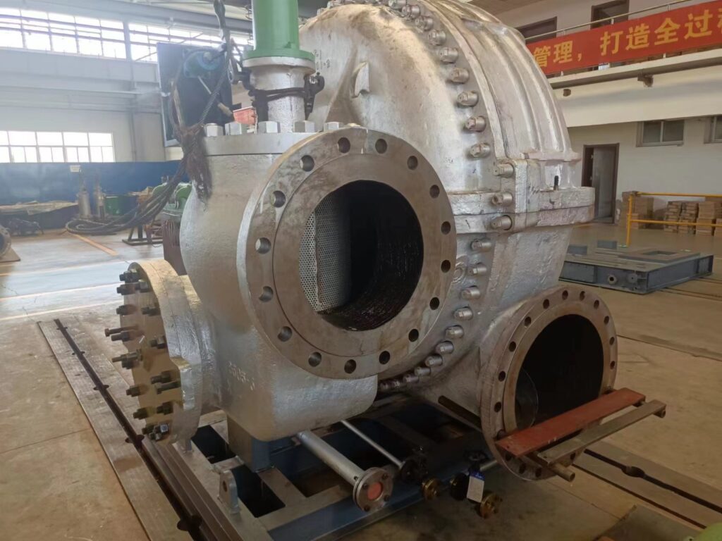
Here’s a detailed exploration of non-condensing steam turbines, presented as a long plain text. Non-condensing steam turbines, also known as back-pressure turbines, are a type of steam turbine where the steam exits at a pressure higher than atmospheric, rather than being condensed into a vacuum as in condensing turbines. These turbines are designed to produce mechanical work—typically to generate electricity or drive machinery—while also supplying usable exhaust steam for industrial processes, heating, or other thermal applications. They are widely used in settings where both power and heat are needed, such as industrial plants, small power stations, and combined heat and power (CHP) systems, with power outputs ranging from a few kilowatts to tens of megawatts. Non-condensing steam turbines are valued for their simplicity, efficiency in CHP applications, and ability to leverage steam as a dual-purpose resource. Let’s dive into their mechanics, design features, applications, operational details, historical context, modern relevance, advantages, and challenges.
The operation of a non-condensing steam turbine follows the Rankine cycle, adapted to prioritize both mechanical power and usable exhaust steam over maximum electrical efficiency. A boiler generates steam by burning fuels like coal, natural gas, oil, biomass (e.g., wood chips, bagasse), or capturing waste heat from industrial processes—say, furnace exhaust at 400-600°C. Steam enters the turbine at pressures typically between 10 and 100 bar and temperatures of 200-540°C, depending on the system’s scale and fuel source. This steam flows over blades attached to a rotor—a steel shaft weighing from a few kilograms in small units to tons in larger ones. As the steam expands—dropping from, say, 50 bar to 5-20 bar—it accelerates to speeds of 300-500 meters per second, pushing the blades and spinning the rotor at speeds like 3,000 RPM for 50 Hz grids, 3,600 RPM for 60 Hz, or up to 10,000 RPM in high-speed designs. The rotor drives a generator to produce electricity or powers machinery like pumps, compressors, or fans via a shaft, often with a gearbox to match equipment speeds. Unlike condensing turbines, the steam does not exhaust into a vacuum (0.05-0.1 bar); instead, it exits at a higher pressure—typically 2-20 bar—determined by downstream needs, such as heating a building, drying materials, or feeding a process like chemical distillation. This exhaust steam retains significant thermal energy, making non-condensing turbines ideal for CHP setups where total energy efficiency is the goal.
The design of non-condensing steam turbines reflects their dual-purpose role and simpler construction compared to condensing systems. They can be single-stage for small applications—say, a 50 kW unit with one blade set—or multi-stage with 5-20 stages for larger outputs like 10 MW, extracting energy gradually across multiple blade rows. Impulse designs are common, especially in smaller units—steam accelerates through nozzles into high-velocity jets that strike curved, bucket-shaped blades, spinning the rotor at high speeds like 10,000-20,000 RPM, a nod to Gustaf de Laval’s 1880s turbine. Reaction designs, inspired by Charles Parsons’ multi-stage concept, dominate in larger non-condensing turbines—steam expands across fixed stator and moving rotor blades, spinning at 3,000-6,000 RPM for efficiency and generator compatibility. Combination designs blend impulse and reaction stages—impulse for high-pressure entry (e.g., 50 bar), reaction for lower-pressure exhaust (e.g., 10 bar)—optimizing energy extraction in mid-sized systems. Blades are sized for the pressure range—5-20 cm in high-pressure sections, up to 50 cm in low-pressure stages—made of stainless steel or nickel alloys (e.g., Inconel) for heat resistance up to 540°C, with coatings like chromium to combat corrosion. Rotors, forged steel, are balanced to handle high speeds, while casings—cast steel or alloys—contain pressures up to 100 bar, with seals like labyrinths or packing glands minimizing leakage, though less critical than in condensing turbines since exhaust pressure is higher.
Non-condensing steam turbine generators pair the turbine with an alternator or dynamo to produce electricity, tailored to the system’s scale. A 1 MW unit might generate 400 V AC for industrial use, while a 50 kW unit produces 230 V AC for a small facility, synchronized at 50 or 60 Hz. Generators are synchronous—rotor poles spin within stator windings—cooled by air or water to manage heat from 50-70% energy losses, with voltage adjustable via regulators. Boilers, producing 10-100 tons/hour of steam, integrate with fuels like natural gas (clean, efficient), biomass (sustainable), or waste heat (cost-free). Unlike condensing systems, non-condensing turbines skip the condenser and cooling towers, reducing complexity—exhaust steam pipes directly to process equipment, radiators, or heat exchangers. Controls vary—manual valves in basic setups, digital systems with sensors in modern units—adjusting steam flow to balance power and heat output, with costs from $10,000 for a 50 kW unit to $1 million for a 10 MW system.
Applications of non-condensing steam turbines center on industries needing both power and heat. Pulp and paper mills use them extensively—a 5 MW turbine burns wood waste, producing 4 MW of electricity and 10 tons/hour of 5-bar steam to dry pulp, leveraging abundant biomass. Chemical plants deploy them for process steam—a 10 MW unit generates 8 MW and 20 tons/hour of 15-bar steam for reactors or distillation, often fueled by natural gas. Sugar mills rely on them with bagasse—a 3 MW turbine powers milling equipment and supplies 8 tons/hour of 10-bar steam for juice evaporation, using cane waste. Textile factories use smaller units—a 500 kW turbine produces 400 kW and 2 tons/hour of 3-bar steam for dyeing or heating, often coal-fired. District heating systems adopt them in cold regions—a 2 MW turbine generates 1.5 MW and heats a small town with 5-bar steam, burning local biomass. Small power plants or cogeneration units use them for grid support—a 20 MW turbine supplies 15 MW and steam for nearby factories, fueled by oil or gas. Off-grid setups benefit too—a 50 kW turbine in a remote farm burns wood, powering tools and heating barns.
Efficiency in non-condensing steam turbines varies by focus. Electrical efficiency is lower than condensing turbines—typically 20-30%—since less steam energy converts to work. A 5 MW unit burning 20 tons/hour of steam (50 bar, 540°C) might produce 1.5 MW (25% efficiency), with 70% of energy exiting as usable 10-bar steam, losing 5-10% to friction and leaks. In CHP mode, total efficiency—power plus heat—reaches 70-85%, far exceeding condensing systems’ 35-45%. For example, a 3 MW turbine converts 25% to electricity (750 kW), 55% to 5-bar steam (1.65 MW thermal), losing 20% to waste. Losses stem from incomplete expansion (exhaust at 5-20 bar vs. 0.05 bar), blade turbulence, and leakage (5-10% with basic seals). Multi-stage designs or superheating to 540°C boost electrical efficiency to 30-35%, but exhaust pressure limits gains—lower exhaust (e.g., 2 bar) increases power but reduces usable heat. Fuel quality affects output—dry biomass (4.5 kWh/kg) outperforms wet (3 kWh/kg), with moisture above 20% cutting steam by 30%.
Historically, non-condensing steam turbines evolved from early steam power needs. Parsons’ 1884 multi-stage turbine and De Laval’s impulse design laid the groundwork, but by the early 20th century, industries adopted them for dual power-and-heat roles, replacing steam engines (5-10% efficiency) with turbines (15-25%). Pre-WWII factories used coal-fired units for machinery and heating, scaling to megawatts by the 1930s. WWII saw them in small plants or ships—e.g., a 1 MW unit powered a factory and warmed it on limited fuel. Post-war, condensing turbines dominated large grids, but the 1970s energy crisis revived non-condensing designs for CHP, especially with biomass and waste heat. Modern units refine this—automation and materials like nickel alloys enhance performance, though they remain niche vs. condensing giants.
Modern relevance ties to energy efficiency and sustainability. Industrial CHP thrives—a 10 MW turbine saves a factory $2-3 million yearly by reusing steam, vs. separate power and heat systems costing 50% more. Biomass use grows—a 5 MW unit burns 2 tons/hour of wood waste, cutting fossil fuel reliance in rural mills. Waste heat recovery expands—a 2 MW turbine uses 400°C exhaust from a steel furnace, generating power and steam emissions-free. District heating in Europe leans on them—a 3 MW turbine heats 500 homes and powers local loads, fueled by gas or biomass. Decentralized power benefits—off-grid sites use 50-500 kW units where grids falter. Innovations help—digital controls optimize steam use, coatings handle 540°C, and modular designs cut costs, though condensing turbines lead in raw power output.
Advantages of non-condensing steam turbines include simplicity—no condenser or cooling towers slashes setup costs ($500-$1,000/kW vs. $1,500-$2,000/kW for condensing). High CHP efficiency (70-85%) maximizes energy use—a 5 MW unit delivers 4 MW and 10 tons/hour of steam, beating standalone generators (30-40%). Fuel flexibility suits local resources—wood, waste, or gas work seamlessly. Compactness fits tight spaces—a 1 MW unit needs 5×10 meters vs. 10×20 for condensing. Reliability endures—20-30 years with maintenance, running 5,000-8,000 hours/year. Sustainability aligns with green goals—biomass units offset CO2, and waste heat cuts fuel bills.
Challenges limit their scope. Lower electrical efficiency (20-30%) caps power output—a 5 MW unit yields 1.5 MW vs. 2 MW from a condensing turbine, needing more fuel (e.g., 2 tons/hour of wood vs. 1.5 tons). Exhaust pressure trade-offs constrain design—5-20 bar balances heat and power but sacrifices electrical gains. Maintenance—blade wear, seal leaks, boiler scaling—costs $10,000-$50,000 yearly for a 5 MW unit, with downtime cutting production. Emissions from biomass (50-200 mg/m³ particulates) need filters ($10,000-$50,000) for compliance (e.g., U.S. EPA 25 mg/m³). Initial costs—$500,000 for 1 MW—lag solar ($1-2/W) for small scales. Fuel logistics—wet biomass or inconsistent heat—drop output by 20-30%.
Examples illustrate their role. A 1 MW turbine in a textile plant burns coal, producing 800 kW and 3 tons/hour of 5-bar steam for dyeing, saving $200,000 yearly. A 10 MW unit in a paper mill uses wood waste, generating 8 MW and 20 tons/hour of 10-bar steam, cutting costs by $2 million. A 50 kW off-grid turbine burns logs, powering a farm and heating it with 2-bar steam, costing $10,000 but saving $5,000 annually.
Non-condensing steam turbines excel where power and heat intertwine, offering a practical, efficient solution for industry and small-scale energy. Their legacy endures, adapting to modern needs with a focus on resourcefulness and sustainability.
Here’s a continued exploration of non-condensing steam turbines, presented as a detailed plain text that builds on the previous discussion while offering deeper insights. Non-condensing steam turbines, often referred to as back-pressure turbines, are a specialized type of steam turbine where the exhaust steam exits at a pressure above atmospheric levels, typically between 2 and 20 bar, rather than being condensed into a vacuum as in condensing turbines. These turbines are engineered to produce mechanical work—usually driving a generator for electricity or powering machinery—while simultaneously providing usable exhaust steam for heating, industrial processes, or other thermal applications. They are particularly suited for combined heat and power (CHP) systems, small industrial plants, and settings where both electrical and thermal energy are valuable, with power outputs ranging from a few kilowatts to tens of megawatts. Non-condensing steam turbines stand out for their simplicity, high total energy efficiency in CHP configurations, and adaptability to diverse fuel sources. Let’s expand further on their mechanics, design characteristics, applications, operational specifics, historical evolution, modern significance, advantages, and challenges.
The mechanics of a non-condensing steam turbine are rooted in the Rankine cycle, tailored to balance mechanical power and thermal output rather than maximizing electrical efficiency alone. A boiler generates steam by combusting fuels such as coal, natural gas, oil, or biomass like wood chips, sawdust, or agricultural residues (e.g., rice husks, sugarcane bagasse), or by harnessing waste heat from industrial processes—imagine exhaust from a kiln at 400-600°C or a diesel engine at 300°C. Steam enters the turbine at pressures typically ranging from 10 to 100 bar and temperatures from 200 to 540°C, depending on the system’s size and fuel quality. This steam flows over blades mounted on a rotor—a forged steel shaft that can weigh a few kilograms in small units or several tons in larger ones. As the steam expands—say, from 50 bar to 10 bar—it accelerates to speeds of 300-500 meters per second, pushing the blades and spinning the rotor at speeds like 3,000 RPM for 50 Hz electrical grids, 3,600 RPM for 60 Hz, or up to 10,000 RPM in high-speed industrial designs. The rotor’s motion drives a generator to produce electricity or powers mechanical equipment such as pumps, compressors, fans, or mills through a shaft, often paired with a gearbox to adjust speed—for example, stepping down 10,000 RPM to 1,500 RPM for a pump. Unlike condensing turbines, which exhaust into a vacuum (0.05-0.1 bar) to extract maximum energy, non-condensing turbines release steam at a higher pressure—2 to 20 bar—set by the needs of downstream applications like heating a factory, drying lumber, or supplying steam for chemical reactions. This exhaust steam retains significant thermal energy, often 50-70% of the input, making these turbines ideal for CHP systems where total energy utilization is prioritized over electrical output alone.
The design of non-condensing steam turbines reflects their practical focus on dual-purpose energy production and reduced complexity compared to condensing systems. They can be single-stage for small-scale use—such as a 50 kW unit with one blade set extracting energy in a single pass—or multi-stage with 5 to 20 stages for larger capacities like 10 MW, allowing progressive energy extraction across multiple blade rows. Impulse designs are frequent in smaller units—steam accelerates through nozzles into high-velocity jets that strike curved, bucket-shaped blades, spinning the rotor at high speeds like 10,000-20,000 RPM, a design echoing Gustaf de Laval’s 1880s impulse turbine. Reaction designs, drawing from Charles Parsons’ multi-stage approach, are more common in larger non-condensing turbines—steam expands across alternating fixed stator and moving rotor blades, spinning at 3,000-6,000 RPM for better efficiency and compatibility with standard generators. Combination designs integrate impulse and reaction stages—impulse for the high-pressure entry (e.g., 50 bar) and reaction for the lower-pressure exhaust (e.g., 10 bar)—optimizing performance in mid-sized systems. Blades vary in size—5-20 cm in high-pressure sections, up to 50 cm in low-pressure stages—crafted from stainless steel for durability or nickel-based alloys like Inconel for heat resistance up to 540°C, often coated with chromium or ceramic to resist corrosion and erosion from wet steam. Rotors, made of forged steel, are precision-balanced to handle high speeds without vibration, while casings—cast steel or alloys—contain pressures up to 100 bar, using seals like labyrinths or packing glands to minimize leakage, though sealing is less critical here since exhaust pressure exceeds atmospheric levels, reducing the pressure differential that drives leaks.
Non-condensing steam turbine generators couple the turbine with an alternator or dynamo to produce electricity, scaled to the system’s needs. A 1 MW unit might generate 400 V AC for industrial machinery, while a 50 kW unit produces 230 V AC for a small facility, synchronized at 50 or 60 Hz for grid or local use. Generators are typically synchronous—rotor poles spin within stator windings—cooled by air or water to dissipate heat from 50-70% energy losses, with voltage adjustable via regulators to match loads. Boilers, producing 10 to 100 tons/hour of steam, integrate with diverse fuels—natural gas offers clean combustion, biomass leverages local waste, and waste heat taps free energy from processes like steelmaking or cement production. Unlike condensing turbines, non-condensing systems eliminate the need for a condenser and associated cooling infrastructure—exhaust steam is piped directly to heat exchangers, process equipment, or heating systems, simplifying installation and maintenance. Control systems range from manual valves and mechanical governors in basic setups to digital controls with sensors in advanced units, adjusting steam flow to optimize the balance between power and heat output, with costs ranging from $10,000 for a 50 kW unit to $1-2 million for a 10 MW system, depending on features and capacity.
Applications of non-condensing steam turbines are centered in industries and settings where both electrical power and thermal energy are in demand. Pulp and paper mills are a prime example—a 5 MW turbine burns wood waste from sawmill operations, producing 4 MW of electricity to run machinery and 10 tons/hour of 5-bar steam to dry paper pulp, capitalizing on abundant biomass to offset grid costs by $1-2 million annually. Chemical plants use them for process steam—a 10 MW turbine generates 8 MW of power and 20 tons/hour of 15-bar steam for reactors, distillation columns, or heating, often fueled by natural gas for consistent output. Sugar mills rely heavily on them with bagasse—a 3 MW turbine powers milling equipment and delivers 8 tons/hour of 10-bar steam to evaporate cane juice, using cane waste to achieve near-self-sufficiency during harvest season. Textile factories employ smaller units—a 500 kW turbine produces 400 kW and 2 tons/hour of 3-bar steam for dyeing fabrics or heating dye vats, often coal-fired in regions with cheap coal access. District heating systems in colder climates adopt them—a 2 MW turbine generates 1.5 MW of electricity and heats a small town with 5-bar steam piped to radiators, burning local biomass like wood pellets for sustainability. Small cogeneration plants use them for grid support—a 20 MW turbine supplies 15 MW to the grid and steam to nearby factories, fueled by oil or gas in urban areas. Off-grid applications benefit as well—a 50 kW turbine in a remote farm burns wood, powering tools and heating livestock barns with 2-bar steam, providing energy independence where grid extension is impractical.
Efficiency in non-condensing steam turbines depends on their operational goals. Electrical efficiency is typically lower than that of condensing turbines—ranging from 20-30%—because the steam expansion stops at a higher exhaust pressure, leaving much of its energy as usable heat. A 5 MW turbine burning 20 tons/hour of steam (50 bar, 540°C) might produce 1.5 MW of electricity (25% efficiency), with 70% of the energy exiting as 10-bar steam (3.5 MW thermal equivalent), and 5-10% lost to friction, turbulence, and leakage. In CHP mode, total efficiency—combining power and heat—reaches 70-85%, far surpassing the 35-45% electrical efficiency of condensing systems. For instance, a 3 MW turbine might convert 25% to electricity (750 kW), 55% to 5-bar steam (1.65 MW thermal), and lose 20% to waste heat. Losses come from incomplete expansion (exhaust at 5-20 bar vs. 0.05 bar in condensing units), blade inefficiencies (less staging than large turbines), and leakage (5-10% with basic seals). Multi-stage designs with 5-20 stages or superheating steam to 540°C can boost electrical efficiency to 30-35%, but lowering exhaust pressure (e.g., to 2 bar) increases power at the expense of usable heat, a trade-off that CHP systems carefully balance. Fuel quality impacts performance—dry biomass at 4.5 kWh/kg outperforms wet biomass at 3 kWh/kg, with moisture levels above 20% reducing steam output by 30% if not pre-dried, a common challenge in biomass-heavy applications.
The historical development of non-condensing steam turbines traces back to the early days of steam power. Charles Parsons’ 1884 multi-stage turbine and Gustaf de Laval’s impulse design provided the foundation, but by the early 20th century, industries adopted non-condensing turbines for their ability to supply both power and heat, outpacing less efficient steam engines (5-10% efficiency) with turbines offering 15-25%. Pre-World War II factories used coal-fired units to drive machinery and heat workspaces, scaling to megawatts by the 1930s as metallurgy improved—chromium steels allowed higher temperatures and pressures. During WWII, non-condensing turbines powered small plants or military facilities—e.g., a 1 MW unit ran a factory and warmed it on rationed fuel, proving their resilience. Post-war, condensing turbines took over large-scale power generation, but the 1970s energy crisis revived non-condensing designs for CHP, particularly with biomass and waste heat as oil prices soared. Modern units enhance this legacy—digital automation optimizes steam use, and materials like nickel alloys withstand 540°C, though they remain a specialized tool compared to condensing systems.
The modern significance of non-condensing steam turbines lies in their efficiency and adaptability in energy-conscious applications. Industrial CHP systems benefit greatly—a 10 MW turbine saves a factory $2-3 million annually by reusing steam for processes, far more cost-effective than separate power generation (30-40% efficiency) and heating systems (50-60% fuel loss). Biomass utilization is on the rise—a 5 MW turbine burns 2 tons/hour of wood waste, reducing fossil fuel dependence in rural industries like sawmills or paper plants, aligning with carbon reduction goals. Waste heat recovery expands their reach—a 2 MW turbine uses 400°C exhaust from a glass furnace, generating power and steam without additional fuel, cutting emissions and costs by $500,000 yearly. District heating systems in Europe and North America rely on them—a 3 MW turbine heats 500 homes and powers local loads with 5-bar steam, often fueled by gas or biomass for reliability and sustainability. Decentralized power applications grow too—a 50-500 kW turbine serves off-grid communities or farms where grid access costs exceed $10,000 per kilometer. Innovations bolster their role—digital controls with real-time sensors balance power and heat, advanced coatings handle higher temperatures, and modular designs reduce installation costs, though condensing turbines dominate in pure power generation.
The advantages of non-condensing steam turbines are numerous and context-specific. Their simplicity—no need for a condenser or cooling towers—reduces initial costs to $500-$1,000 per kW, compared to $1,500-$2,000/kW for condensing systems, and cuts maintenance by eliminating complex cooling infrastructure. High CHP efficiency (70-85%) maximizes energy use—a 5 MW turbine delivers 4 MW of electricity and 10 tons/hour of usable steam, outperforming standalone generators or boilers in total energy output. Fuel flexibility accommodates local resources—wood, agricultural waste, gas, or waste heat work effectively, making them viable in diverse settings like forested regions or industrial zones. Their compact size fits constrained spaces—a 1 MW unit requires a 5×10-meter footprint versus 10×20 meters for a condensing setup, easing installation in factories or small plants. Reliability is strong—units run 20-30 years with regular maintenance, operating 5,000-8,000 hours/year in harsh conditions like dusty mills or humid climates. Sustainability appeals to green initiatives—biomass-driven units achieve near carbon neutrality with regrowth, and waste heat recovery minimizes fuel use, supporting eco-friendly operations.
Challenges, however, temper their broader adoption. Their lower electrical efficiency (20-30%) limits power output—a 5 MW turbine yields 1.5 MW of electricity compared to 2 MW from a condensing turbine with the same input, requiring more fuel (e.g., 2 tons/hour of wood versus 1.5 tons) for equivalent power. The trade-off between exhaust pressure and power constrains design—higher exhaust pressures (10-20 bar) preserve heat but reduce electrical yield, while lower pressures (2-5 bar) boost power at the cost of thermal utility, a delicate balance for CHP optimization. Maintenance needs—blade wear from wet steam, seal leakage, and boiler scaling—cost $10,000-$50,000 annually for a 5 MW unit, with downtime interrupting power or heat supply, a concern in continuous operations. Emissions from biomass fuels—particulates at 50-200 mg/m³ and CO—require filters or scrubbers costing $10,000-$50,000 to meet regulations like the U.S. EPA’s 25 mg/m³ limit, adding expense and complexity. Initial costs, while lower than condensing systems, remain significant—$500,000 for a 1 MW unit can’t compete with solar’s $1-2/W for small-scale power. Fuel logistics pose risks—wet biomass (e.g., 50% moisture) or inconsistent waste heat reduces steam quality, cutting output by 20-30% if not managed with drying or buffering systems.
Examples showcase their practical impact. A 1 MW non-condensing turbine in a textile plant burns coal, producing 800 kW of electricity and 3 tons/hour of 5-bar steam for dyeing, saving $200,000 annually on energy bills with a $400,000 setup cost. A 10 MW turbine in a paper mill uses wood waste, generating 8 MW and 20 tons/hour of 10-bar steam for drying, reducing costs by $2 million yearly against a $2 million investment. A 50 kW off-grid turbine in a rural farm burns logs, powering tools with 40 kW and heating a barn with 2-bar steam, costing $10,000 but saving $5,000 annually over diesel generators.
Non-condensing steam turbines shine where power and heat converge, offering a streamlined, efficient solution for industries, small plants, and off-grid sites. Their evolution—from early 20th-century factories to modern CHP systems—reflects a focus on resource efficiency and adaptability, ensuring they remain relevant in a world balancing energy needs with sustainability.
Condensing Steam Turbine
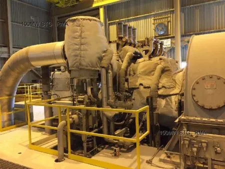
Here’s a detailed exploration of condensing steam turbines, presented as a long plain text. Condensing steam turbines are a type of steam turbine designed to maximize electrical power generation by exhausting steam into a vacuum, typically at 0.05 to 0.1 bar, rather than at a higher pressure as in non-condensing turbines. This low exhaust pressure allows the steam to expand fully, extracting the maximum possible energy to drive a rotor, which in turn powers a generator or machinery. Widely used in utility-scale power plants, large industrial facilities, and some renewable energy systems, condensing steam turbines range in capacity from a few kilowatts to over 1,000 megawatts, with a focus on achieving high electrical efficiency—typically 35-45%—at the expense of rejecting significant heat as waste. They are complex systems requiring boilers, condensers, and cooling infrastructure, making them suited for applications where electricity is the primary goal. Let’s dive into their mechanics, design features, applications, operational details, historical context, modern relevance, advantages, and challenges.
The mechanics of a condensing steam turbine are based on the Rankine cycle, optimized to convert as much thermal energy as possible into mechanical work. A boiler generates steam by burning fuels like coal, natural gas, oil, or biomass (e.g., wood chips, agricultural waste), or using heat from nuclear fission or concentrated solar power, producing steam at high pressures—typically 50 to 300 bar—and temperatures of 400-600°C, depending on the system’s scale and technology. This steam enters the turbine, flowing over blades attached to a rotor—a massive forged steel shaft weighing tons in large units or kilograms in smaller ones. As the steam expands—dropping from, say, 100 bar to 0.05 bar—it accelerates to speeds of 500-700 meters per second, pushing the blades and spinning the rotor at speeds like 3,000 RPM for 50 Hz grids, 3,600 RPM for 60 Hz, or up to 10,000 RPM in smaller, high-speed designs. The rotor drives a generator to produce electricity or, less commonly, powers machinery like pumps or compressors via a shaft, often with a gearbox to adjust speed. Unlike non-condensing turbines, which exhaust at 2-20 bar for heat use, condensing turbines release steam into a condenser—a heat exchanger that cools the steam back to water at 30-50°C using cold water from rivers, oceans, or cooling towers, or air in dry regions—creating a vacuum that maximizes the pressure drop and energy extraction. This condensed water is then pumped back to the boiler, closing the cycle, while the cooling process rejects 50-60% of the input energy as waste heat.
The design of condensing steam turbines is complex and tailored for high efficiency across a wide pressure range. They are typically multi-stage, with 10 to 50 stages grouped into high-pressure (HP), intermediate-pressure (IP), and low-pressure (LP) sections, each optimized for its steam conditions. HP stages handle initial conditions—e.g., 300 bar, 600°C—with small, robust blades (5-20 cm) made of nickel-based alloys like Inconel to withstand extreme heat and pressure, often coated with chromium or ceramics to resist creep and corrosion. IP stages manage reheated steam—say, 50 bar, 540°C—while LP stages process low-pressure, high-volume steam (0.05 bar) with massive blades up to 2 meters long, made of titanium or stainless steel to resist erosion from wet steam at tip speeds of 500-700 m/s. Impulse designs dominate HP stages—steam jets from nozzles strike buckets—while reaction designs prevail in LP stages, where steam expands across moving blades, blending both in combination turbines for optimal energy extraction. Rotors, weighing 10-100 tons in large units, are precision-balanced to spin without vibration, connected to generators via direct shafts or couplings. Casings, forged steel or alloys, contain pressures up to 300 bar, with labyrinth seals minimizing leakage across stages—critical given the huge pressure drop to vacuum. Condensers, often shell-and-tube or surface types, use 1-2 liters of cooling water per kWh, rejecting heat to maintain the vacuum, supported by cooling towers or air fans that evaporate 1-2% of output as waste.
Condensing steam turbine generators pair the turbine with a synchronous generator to produce electricity, scaled to the system’s capacity. A 500 MW unit generates 13.8 kV AC for grid transmission, while a 5 MW industrial unit produces 400 V AC, synchronized at 50 or 60 Hz. Generators feature rotor poles spinning within stator windings, cooled by hydrogen (large units) or air (smaller ones) to dissipate heat from 50-60% losses, with transformers stepping up voltage for distribution. Boilers, producing 100-1,000 tons/hour of steam, integrate with fuels like coal (high energy), gas (clean), or biomass (sustainable), or heat from nuclear reactors or solar mirrors. Cooling systems are extensive—water towers process millions of liters daily, while air-cooled condensers suit arid areas, though less efficient. Controls are sophisticated—digital systems with sensors monitor pressure, temperature, and vacuum, adjusting steam flow and cooling to optimize output, with costs from $50,000 for a 5 MW unit to $50 million for a 500 MW plant.
Applications of condensing steam turbines are primarily in power generation. Utility power plants dominate—coal-fired units (37% of global power) range from 100-1,000 MW, gas-fired combined-cycle plants (25%) hit 500-1,500 MW, and nuclear plants (10%) reach 1,000-1,750 MW, powering millions of homes—e.g., a 1,200 MW nuclear turbine serves 1.5 million households. Large industrial facilities use smaller units—a 5-50 MW turbine powers a steel mill or refinery, fueled by gas or waste heat, supplying all onsite needs. Biomass plants adopt them for renewables—a 10-50 MW unit burns 2-10 tons/hour of wood, supporting rural grids or factories. Geothermal systems use them—a 5-100 MW turbine taps underground steam at 10-50 bar, common in Iceland or the U.S. West. Solar thermal plants employ them—a 50-200 MW unit uses mirrors to heat steam, as in Spain’s solar farms. Off-grid or backup systems use small units—a 50 kW turbine in a remote mine runs on diesel, powering critical loads. Their focus is electricity, not heat, making them less common in CHP compared to non-condensing turbines.
Efficiency in condensing steam turbines is higher than non-condensing types, typically 35-45% for electrical output, thanks to the large pressure drop to vacuum. A 500 MW turbine with supercritical steam (600°C, 300 bar) might convert 45% of fuel energy to electricity, losing 55% to condenser heat, friction, and leaks. Subcritical units (540°C, 100 bar) hit 35-40%, while small units (5 MW, 20 bar) drop to 25-30%. Losses include condenser heat (50-60%), blade turbulence (2-5%), and moisture in LP stages (5-10% output drop unless superheated or dried with separators). Enhancements like reheat—returning steam to the boiler at 20-50 bar for reheating to 540°C—add 4-5% efficiency, common in coal plants. Supercritical or ultra-supercritical steam (600-700°C, 300 bar) pushes efficiency to 47-50%, nearing the Rankine ideal of 60%. Fuel quality matters—coal (30 MJ/kg) outperforms wet biomass (10-15 MJ/kg), with moisture reducing steam output by 20-30% if not managed.
Historically, condensing steam turbines emerged with the rise of centralized power. Parsons’ 1884 turbine pioneered multi-stage design, scaling to megawatts by 1900 as electricity demand grew, outpacing steam engines (5-10% efficiency) with 20-30%. Early 20th-century coal plants used them, with metallurgy advances—nickel steels—enabling higher pressures by the 1930s. WWII saw them in naval ships and power stations, while post-war nuclear and gas plants adopted them, with reheat (1930s) and supercritical steam (1950s) lifting efficiency to 40%+. The 1970s energy crisis spurred efficiency focus, though renewables later diversified their use. Modern designs leverage CFD for blade optimization and AI for control, maintaining their dominance in power generation.
Modern relevance centers on large-scale electricity. Utility plants rely on them—coal, gas, and nuclear units like the 1,750 MW Arabelle power grids, though coal declines with emissions rules (e.g., Paris Agreement). Industrial self-generation grows—a 20 MW turbine cuts a factory’s $5 million yearly grid bill. Renewables expand their role—biomass (10-50 MW), geothermal (5-100 MW), and solar thermal (50-200 MW) support green energy, with a 20 MW wood-fired unit powering 10,000 homes. Innovations enhance them—ceramic blades handle 1,000°C, 3D-printed parts cut costs, and AI optimizes vacuum, though gas turbines challenge them in flexibility. Their scale—1,000 MW+—keeps them vital for baseload power.
Advantages include high electrical efficiency (35-45%), maximizing power—a 500 MW unit outproduces a non-condensing twin by 50%. Large capacity (up to 1,750 MW) suits grids, with a single turbine powering cities. Fuel flexibility spans coal, gas, nuclear, and renewables, adapting to local resources. Longevity—30-50 years—ensures reliability, running 8,000 hours/year. Challenges are complexity—condensers and cooling towers raise costs to $1,500-$2,000/kW vs. $500-$1,000/kW for non-condensing, with $100,000-$1 million yearly maintenance. Water use (1-2 liters/kWh) strains dry regions, and heat rejection (50-60%) wastes energy, unfit for CHP. Slow startups (hours vs. minutes for gas turbines) limit responsiveness.
Examples highlight their impact. A 1,000 MW coal turbine produces 800 MW, powering 1 million homes with a $50 million cost. A 10 MW biomass unit burns 2 tons/hour of wood, generating 8 MW for a rural grid, costing $5 million. A 50 kW diesel-fired turbine in a mine delivers 40 kW, costing $50,000.
Condensing steam turbines are power generation titans, excelling where electricity reigns supreme, their complexity offset by unmatched output and efficiency in a grid-driven world.
Here’s a continued exploration of condensing steam turbines, presented as a detailed plain text that builds on the previous discussion while offering deeper insights. Condensing steam turbines are engineered to maximize electrical power generation by expanding steam to a low-pressure vacuum, typically 0.05 to 0.1 bar, allowing for the greatest possible energy extraction from steam before it is condensed back into water. Unlike non-condensing turbines, which exhaust at higher pressures for heat use, condensing turbines prioritize electricity over thermal output, making them a cornerstone of utility-scale power plants, large industrial facilities, and certain renewable energy systems. With capacities ranging from a few kilowatts to over 1,000 megawatts, they achieve electrical efficiencies of 35-45%, or even higher with advanced designs, at the cost of rejecting significant waste heat. Their complexity—requiring boilers, condensers, and extensive cooling systems—suits applications where power generation is the primary goal. Let’s delve further into their mechanics, design intricacies, applications, operational specifics, historical evolution, modern significance, advantages, and challenges.
The mechanics of a condensing steam turbine are rooted in the Rankine cycle, optimized to extract maximum mechanical work from steam. A boiler generates steam by combusting fuels like coal, natural gas, oil, or biomass (e.g., wood pellets, straw), or harnessing heat from nuclear reactors, geothermal wells, or concentrated solar power, producing steam at pressures of 50 to 300 bar and temperatures of 400-600°C, with supercritical designs reaching 700°C. This high-pressure steam enters the turbine, flowing over blades mounted on a rotor—a massive forged steel shaft that can weigh 10-100 tons in large units or just a few kilograms in smaller ones. As the steam expands—dropping from, say, 100 bar to 0.05 bar—it accelerates to speeds of 500-700 meters per second, pushing the blades and spinning the rotor at speeds like 3,000 RPM for 50 Hz electrical grids, 3,600 RPM for 60 Hz, or up to 10,000 RPM in smaller, high-speed configurations. The rotor drives a generator to produce electricity or, less commonly, powers machinery such as pumps or compressors through a shaft, often with a gearbox to adjust speed—for instance, reducing 10,000 RPM to 1,500 RPM for industrial equipment. The steam then exhausts into a condenser—a heat exchanger that cools it back to water at 30-50°C using cold water from rivers, oceans, or cooling towers, or air in water-scarce areas—creating a vacuum that maximizes the pressure differential and energy yield. This condensed water is pumped back to the boiler, completing the closed cycle, while the cooling process discards 50-60% of the input energy as waste heat, a trade-off for high electrical output.
The design of condensing steam turbines is intricate, built to handle a broad pressure range and optimize efficiency. They are almost always multi-stage, featuring 10 to 50 stages divided into high-pressure (HP), intermediate-pressure (IP), and low-pressure (LP) sections, each tailored to its steam conditions. HP stages manage the initial high-pressure, high-temperature steam—e.g., 300 bar, 600°C—with small, sturdy blades (5-20 cm) made of nickel-based superalloys like Inconel 718 or Rene 41, designed to resist creep and corrosion at extreme conditions, often coated with chromium carbide or ceramics for durability. IP stages process reheated steam—say, 50 bar, 540°C—while LP stages handle low-pressure, high-volume steam (0.05 bar) with enormous blades, sometimes 1.5-2 meters long, made of titanium or stainless steel to withstand erosion from wet steam droplets at tip speeds of 500-700 m/s. Impulse designs are typical in HP stages—steam accelerates through nozzles into jets that strike bucket-shaped blades—while reaction designs dominate LP stages, where steam expands across moving blades, with combination turbines blending both for efficiency across stages. Rotors, weighing tons, are precision-balanced to spin without vibration, connected to generators via direct shafts or couplings. Casings, forged from high-strength steel or alloys, contain pressures up to 300 bar, with labyrinth seals or brush seals minimizing leakage—a critical feature given the steep drop to vacuum. Condensers, often shell-and-tube or surface designs, use 1-2 liters of cooling water per kWh or air fans, maintaining the vacuum while rejecting heat, supported by cooling towers that evaporate 1-2% of output as waste or air systems that reduce water use at a 5-10% efficiency cost.
Condensing steam turbine generators pair the turbine with a synchronous generator to produce electricity, sized for the application. A 500 MW utility unit generates 13.8 kV AC for grid transmission, stepped up to 220-500 kV, while a 5 MW industrial unit produces 400 V AC for local use, synchronized at 50 or 60 Hz. Generators feature rotor poles spinning within stator windings, cooled by hydrogen in large units (better heat transfer) or air in smaller ones, dissipating heat from 50-60% energy losses, with transformers and regulators adjusting output. Boilers, producing 100-1,000 tons/hour of steam, integrate with fuels like coal (30 MJ/kg), natural gas (clean, 50 MJ/kg), or biomass (10-20 MJ/kg), or heat from nuclear reactors (saturated steam at 70 bar) or solar mirrors (400-540°C). Cooling systems are extensive—water-based condensers process millions of liters daily, with cooling towers rejecting heat via evaporation, while air-cooled condensers suit arid regions, though they lower efficiency by 5-10%. Controls are advanced—digital systems with sensors monitor pressure, temperature, vacuum levels, and rotor speed, adjusting steam flow and cooling water to maximize output, with costs ranging from $50,000 for a 5 MW unit to $50-100 million for a 500-1,000 MW plant.
Applications of condensing steam turbines focus on power generation where electricity is the priority. Utility power plants are their stronghold—coal-fired units (37% of global power) range from 100-1,000 MW, gas-fired combined-cycle plants (25%) reach 500-1,500 MW with gas turbine integration, and nuclear plants (10%) hit 1,000-1,750 MW, powering millions—e.g., a 1,200 MW nuclear turbine serves 1.5-2 million homes. Large industrial facilities use them for self-generation—a 5-50 MW turbine powers a chemical plant or steel mill, fueled by gas, coal, or waste heat, meeting onsite demand without grid reliance. Biomass plants leverage them for renewable energy—a 10-50 MW unit burns 2-10 tons/hour of wood or agricultural waste, supplying rural grids or industrial parks, common in Scandinavia or North America. Geothermal systems depend on them—a 5-100 MW turbine uses steam from underground reservoirs at 10-50 bar, as in New Zealand or the U.S. Geothermal Belt. Solar thermal plants employ them—a 50-200 MW unit uses concentrated sunlight to heat steam, as in California’s solar farms. Off-grid or backup systems use smaller units—a 50 kW turbine in a remote mine runs on diesel or biomass, powering critical equipment. Unlike non-condensing turbines, they rarely serve CHP, as their heat is discarded, not reused.
Efficiency in condensing steam turbines is among the highest for steam-based systems, typically 35-45% for electrical output, driven by the large pressure drop to vacuum. A 500 MW turbine with supercritical steam (600°C, 300 bar) might achieve 45% efficiency, converting 45% of fuel energy to electricity and losing 55% to condenser heat, friction, and leaks. Subcritical units (540°C, 100 bar) reach 35-40%, while small units (5 MW, 20 bar) drop to 25-30% due to scale and simpler staging. Losses include condenser heat rejection (50-60%), blade turbulence (2-5%), and moisture in LP stages (5-10% output reduction unless superheated to 540-600°C or dried with moisture separators). Reheat cycles—returning steam to the boiler at 20-50 bar for reheating to 540°C—boost efficiency by 4-5%, standard in coal and nuclear plants, while double reheat adds another 2-3% in ultra-efficient designs. Supercritical (600°C, 300 bar) and ultra-supercritical (700°C, 350 bar) steam push efficiency to 47-50%, nearing the Rankine ideal of 60%, though material limits (creep, corrosion) cap gains. Fuel quality impacts output—coal (30 MJ/kg) or gas (50 MJ/kg) outperforms wet biomass (10-15 MJ/kg), with high moisture (20-50%) cutting steam production by 20-30% unless pre-dried.
Historically, condensing steam turbines emerged as electricity demand surged. Charles Parsons’ 1884 multi-stage turbine laid the foundation, generating 7.5 kW and proving the concept, scaling to megawatts by 1900 as grids expanded, surpassing steam engines (5-10% efficiency) with 20-30%. Early 20th-century coal plants adopted them, with metallurgy advances—nickel and chromium steels—enabling higher pressures and temperatures by the 1930s. World War II saw them in naval ships (e.g., 29,000 hp on the Titanic) and power stations, while post-war nuclear plants (1950s) and gas combined-cycle systems (1970s) embraced them, with reheat (1930s) and supercritical steam (1950s) lifting efficiency to 40%+. The 1970s energy crisis drove efficiency improvements, and renewables later diversified their fuel sources. Modern designs use computational fluid dynamics (CFD) for blade optimization, advanced alloys for durability, and AI for real-time control, cementing their role in power generation.
Modern significance reflects their dominance in electricity production. Utility plants depend on them—coal, gas, and nuclear units like the 1,750 MW Arabelle turbine power grids, though coal’s share shrinks under emissions policies (e.g., net-zero by 2050 goals). Industrial self-generation rises—a 20 MW turbine saves a refinery $5-10 million yearly vs. grid power, fueled by gas or waste heat. Renewables expand their scope—biomass (10-50 MW), geothermal (5-100 MW), and solar thermal (50-200 MW) align with green energy, with a 20 MW biomass unit powering 10,000 homes on 4 tons/hour of wood. Innovations keep them competitive—ceramic blades tolerate 1,000°C, 3D-printed components reduce costs by 10-20%, and AI maintains vacuum efficiency, though gas turbines (faster startups) and solar (lower cost/W) challenge them. Their scale—500-1,000 MW+—ensures they remain critical for baseload power in a decarbonizing world.
Advantages include high electrical efficiency (35-45%), outpacing non-condensing turbines (20-30%)—a 500 MW unit produces 225 MW vs. 150 MW from a non-condensing peer. Massive capacity (up to 1,750 MW) powers entire regions—a single turbine supports 2 million homes. Fuel flexibility spans coal, gas, nuclear, biomass, and solar, adapting to local conditions. Longevity—30-50 years with maintenance—delivers reliability, running 8,000 hours/year. Challenges are significant—complexity drives costs to $1,500-$2,000/kW vs. $500-$1,000/kW for non-condensing, with $100,000-$1 million yearly maintenance for condensers, blades, and boilers. Water demand (1-2 liters/kWh) strains arid areas—e.g., a 500 MW plant uses 2 million liters/hour—while air cooling cuts efficiency by 5-10%. Heat rejection (50-60%) wastes energy, making them unfit for CHP, and slow startups (hours vs. minutes for gas turbines) limit flexibility.
Examples illustrate their scope. A 1,000 MW coal turbine generates 800 MW, powering 1 million homes with a $50-70 million cost. A 10 MW biomass unit burns 2 tons/hour of wood, producing 8 MW for a rural grid, costing $5-7 million. A 50 kW diesel-fired turbine in a mine delivers 40 kW, costing $50,000 but saving $20,000 yearly vs. generators.
Condensing steam turbines are power generation heavyweights, excelling where electricity is king, their intricate design and high output anchoring grids and industries despite a shifting energy landscape.
Automatic Extraction Non Condensing Turbine
Here’s a detailed exploration of automatic extraction non-condensing steam turbines, presented as a long plain text. Automatic extraction non-condensing steam turbines, also known as extraction back-pressure turbines, are a specialized type of steam turbine designed to produce mechanical power—typically for electricity generation or driving machinery—while simultaneously extracting steam at one or more intermediate pressures for industrial processes or heating, with the final exhaust exiting at a pressure above atmospheric levels, usually 2-20 bar. Unlike condensing turbines, which exhaust into a vacuum to maximize power, these turbines prioritize flexibility, balancing electrical output with the delivery of usable steam at specific pressures tailored to downstream needs. They are widely used in industrial settings like chemical plants, refineries, and paper mills, as well as in combined heat and power (CHP) systems, with capacities ranging from a few kilowatts to tens of megawatts. The “automatic” feature refers to sophisticated control systems that adjust extraction flows in real time, ensuring optimal performance under varying demands. Let’s dive into their mechanics, design features, applications, operational details, historical context, modern relevance, advantages, and challenges.
The mechanics of an automatic extraction non-condensing steam turbine are based on the Rankine cycle, modified to allow controlled steam extraction and a non-condensing exhaust. A boiler generates steam by burning fuels such as coal, natural gas, oil, or biomass (e.g., wood chips, bagasse), or capturing waste heat from industrial processes—say, exhaust from a furnace at 400-600°C. Steam enters the turbine at high pressures, typically 20-100 bar, and temperatures of 200-540°C, depending on the system’s scale and fuel source. This steam flows over blades mounted on a rotor—a forged steel shaft weighing from a few kilograms in small units to several tons in larger ones. As the steam expands—dropping from, say, 50 bar to an extraction point at 15 bar, then to a final exhaust at 5 bar—it accelerates to speeds of 300-500 meters per second, pushing the blades and spinning the rotor at speeds like 3,000 RPM for 50 Hz grids, 3,600 RPM for 60 Hz, or up to 10,000 RPM in high-speed designs. The rotor drives a generator to produce electricity or powers machinery like pumps or compressors via a shaft, often with a gearbox to adjust speed. Steam is extracted at one or more intermediate stages—e.g., 15 bar for a chemical process, 3 bar for heating—through extraction ports controlled by automatic valves, with the remaining steam exhausting at a higher-than-atmospheric pressure (2-20 bar) for additional thermal use, such as drying or district heating. This dual-purpose operation, managed by automated controls, distinguishes them from simpler non-condensing turbines.
The design of automatic extraction non-condensing steam turbines is complex, blending flexibility with efficiency. They are multi-stage, typically with 5-20 stages divided into sections: an initial high-pressure (HP) section before the first extraction, intermediate sections for each extraction point, and a final low-pressure (LP) section before exhaust. HP stages handle entry conditions—e.g., 50 bar, 540°C—with small blades (5-20 cm) made of nickel alloys like Inconel to resist heat and pressure, coated with chromium for durability. Extraction stages manage mid-range pressures—e.g., 15 bar—with blades sized accordingly (10-30 cm), while LP stages process the final expansion to 5-20 bar with larger blades (up to 50 cm), often stainless steel to handle wetter steam. Impulse designs are used in HP stages—steam jets strike buckets—while reaction designs dominate LP stages, with combination turbines blending both for efficiency across pressure drops. Extraction ports, fitted with throttling valves or nozzles, divert steam to external piping, with flow rates adjusted by automatic control systems—e.g., PLCs or DCS—responsive to downstream demand signals. Rotors, forged steel, are balanced for high speeds, while casings—cast steel or alloys—contain 100 bar, with labyrinth seals minimizing leakage, less critical here than in condensing turbines due to higher exhaust pressure. No condenser is needed, simplifying the system—exhaust steam pipes directly to process or heating loads.
Automatic extraction non-condensing steam turbine generators pair the turbine with a synchronous generator, sized for the application. A 10 MW unit might produce 400 V or 13.8 kV AC, synchronized at 50 or 60 Hz, while a 500 kW unit generates 230 V AC for local use. Generators feature rotor poles spinning in stator windings, cooled by air or water, with voltage regulators adjusting output as extraction varies power. Boilers, producing 10-100 tons/hour, use fuels like natural gas (clean), biomass (local), or waste heat (free). Controls are the heart of the “automatic” feature—sensors monitor steam pressure, temperature, and flow at extraction points and exhaust, feeding data to a control system that adjusts valves in real time, ensuring stable power and steam delivery under fluctuating loads. Costs range from $50,000 for a 500 kW unit to $2-5 million for a 10-20 MW system, reflecting added complexity.
Applications center on industries needing variable steam and power. Chemical plants use them extensively—a 10 MW turbine extracts 15-bar steam (10 tons/hour) for reactors and 3-bar steam (5 tons/hour) for heating, producing 7 MW of electricity, fueled by gas or waste heat. Refineries rely on them—a 20 MW unit extracts 20-bar steam for cracking and 5-bar steam for distillation, generating 15 MW, often burning refinery byproducts. Paper mills adopt them—a 5 MW turbine extracts 10-bar steam (8 tons/hour) to dry pulp and exhausts at 2 bar for heating, producing 4 MW from wood waste. Sugar mills use them with bagasse—a 3 MW turbine extracts 15-bar steam for evaporators and exhausts at 5 bar, generating 2 MW. Food processing plants employ smaller units—a 1 MW turbine extracts 5-bar steam for sterilization and exhausts at 2 bar, producing 800 kW. District heating with power generation uses them—a 5 MW turbine extracts 10-bar steam for industrial use and exhausts at 3 bar for homes, generating 4 MW. Off-grid setups benefit too—a 100 kW turbine extracts 5-bar steam for a farm process and exhausts at 2 bar, powering 80 kW.
Efficiency balances power and heat. Electrical efficiency is 20-35%, lower than condensing turbines (35-45%) due to extraction and higher exhaust pressure. A 10 MW turbine (50 bar, 540°C) might produce 3 MW (30% efficiency), with 40% as extracted steam (15 bar), 25% as exhaust steam (5 bar), and 5-10% lost to leaks and friction. Total CHP efficiency hits 70-85%, excelling in energy use—e.g., a 5 MW unit yields 1.5 MW power, 2 MW extracted steam, and 1 MW exhaust heat. Losses include incomplete expansion (5-20 bar exhaust vs. 0.05 bar), blade inefficiencies, and leakage (5-10%). Multi-stage designs and superheating to 540°C boost electrical efficiency to 35%, but extraction reduces available steam for power. Fuel quality matters—dry biomass (4.5 kWh/kg) outperforms wet (3 kWh/kg), with 20%+ moisture cutting output by 30%.
Historically, these turbines evolved from early 20th-century needs for flexible steam use. Parsons’ 1884 multi-stage design and De Laval’s impulse turbine enabled extraction concepts, adopted by industries by the 1920s over steam engines (5-10% efficiency) for 15-25% efficiency plus heat. Pre-WWII plants used coal-fired units for power and process steam, scaling up by the 1930s. WWII saw them in factories needing adaptability, while post-war automation (1950s-60s) added control sophistication. The 1970s energy crisis boosted CHP use, with biomass and waste heat rising. Modern designs leverage digital controls and alloys for efficiency.
Modern relevance lies in industrial flexibility and CHP. Chemical and refining sectors save $1-3 million yearly—a 10 MW turbine meets variable steam needs cost-effectively. Biomass use grows—a 5 MW unit burns 2 tons/hour of waste, cutting fossil fuel costs. Waste heat recovery expands—a 2 MW turbine uses 400°C exhaust, saving $500,000 annually. District heating pairs them with power—a 5 MW unit heats 1,000 homes and generates 4 MW. Automation—PLCs, sensors—optimizes performance, while coatings handle 540°C, though condensing turbines lead in pure power.
Advantages include flexibility—automatic extraction meets shifting demands, e.g., 15-bar to 5-bar steam on the fly. High CHP efficiency (70-85%) maximizes energy—a 5 MW unit delivers 4 MW total output. Simplicity—no condenser—cuts costs to $500-$1,000/kW vs. $1,500-$2,000/kW for condensing. Fuel flexibility suits coal, biomass, or waste heat. Reliability lasts 20-30 years, running 5,000-8,000 hours/year. Challenges are lower electrical efficiency (20-35%)—a 10 MW unit yields 3 MW vs. 4-5 MW condensing. Complexity of controls raises costs—$50,000-$100,000 for automation. Maintenance—valves, blades, seals—costs $10,000-$50,000 yearly. Biomass emissions (50-200 mg/m³) need filters ($10,000-$50,000). Fuel inconsistency cuts output by 20-30%.
Examples show their value. A 10 MW refinery turbine extracts 20-bar and 5-bar steam, producing 7 MW, saving $2 million yearly. A 1 MW food plant unit extracts 5-bar steam, generates 800 kW, costing $100,000 but saving $50,000 annually. A 5 MW paper mill turbine extracts 10-bar steam, exhausts at 2 bar, producing 4 MW from wood, saving $1 million.
Automatic extraction non-condensing turbines excel in balancing power and steam, their adaptability and efficiency making them vital for industries needing both, bridging legacy steam tech with modern demands.
Here’s a continued exploration of automatic extraction non-condensing steam turbines, presented as a detailed plain text that builds on the previous discussion with added depth and nuance. Automatic extraction non-condensing steam turbines, often called extraction back-pressure turbines, are advanced steam turbines designed to generate mechanical power—typically for electricity or machinery—while extracting steam at one or more intermediate pressures for industrial processes or heating, with the final exhaust exiting at a pressure above atmospheric levels, usually 2-20 bar. Unlike condensing turbines that exhaust into a vacuum for maximum power, these turbines offer a flexible balance between electrical output and thermal energy delivery, with automatic control systems adjusting extraction flows to meet real-time demands. They are ideal for industrial applications like refineries, chemical plants, and pulp mills, as well as combined heat and power (CHP) setups, with capacities ranging from a few kilowatts to tens of megawatts. Their ability to adapt to variable steam needs while maintaining efficiency makes them a standout choice in complex energy systems. Let’s delve deeper into their mechanics, design intricacies, applications, operational specifics, historical evolution, modern significance, advantages, and challenges.
The mechanics of an automatic extraction non-condensing steam turbine follow the Rankine cycle, tailored to provide both power and controlled steam output. A boiler produces steam by combusting fuels such as coal, natural gas, oil, or biomass (e.g., wood pellets, rice husks, or sugarcane bagasse), or by capturing waste heat from sources like industrial exhausts at 400-600°C or engine tailpipes at 300-400°C. Steam enters the turbine at high pressures—typically 20-100 bar—and temperatures of 200-540°C, depending on the system’s design and fuel. This steam flows over blades mounted on a rotor—a forged steel shaft ranging from a few kilograms in small units to several tons in larger ones. As the steam expands—say, from 50 bar to an extraction point at 15 bar, then to a final exhaust at 5 bar—it accelerates to speeds of 300-500 meters per second, driving the blades and spinning the rotor at speeds like 3,000 RPM for 50 Hz grids, 3,600 RPM for 60 Hz, or up to 10,000 RPM in high-speed configurations. The rotor powers a generator for electricity or drives machinery like pumps, fans, or compressors via a shaft, often with a gearbox—e.g., reducing 10,000 RPM to 1,500 RPM for a pump. Steam is extracted at intermediate stages—e.g., 15 bar for a process, 3 bar for preheating—through ports with automatic valves, while the remaining steam exhausts at 2-20 bar for additional thermal use, such as drying or heating. Automated controls—sensors and actuators tied to a programmable logic controller (PLC) or distributed control system (DCS)—adjust extraction flows dynamically, ensuring stable power and steam delivery as demands shift, a key feature setting them apart from manual extraction turbines.
The design of these turbines is sophisticated, engineered for flexibility and multi-stage operation. They feature 5-20 stages, segmented into high-pressure (HP) sections before the first extraction, intermediate sections for each extraction point, and a low-pressure (LP) section before exhaust. HP stages handle inlet steam—e.g., 50 bar, 540°C—with small blades (5-20 cm) made of nickel-based alloys like Inconel 718 or Hastelloy, resistant to 540°C and 100 bar, often coated with chromium carbide or ceramics to combat creep and corrosion. Extraction stages manage mid-range pressures—e.g., 15 bar or 5 bar—with blades (10-30 cm) sized for flow, while LP stages process the final drop to 5-20 bar with larger blades (up to 50 cm), typically stainless steel to handle wetter steam. Impulse designs dominate HP stages—steam jets from nozzles strike buckets—while reaction designs prevail in LP stages, with steam expanding across moving blades; combination turbines blend both for efficiency across the pressure range. Extraction ports, equipped with throttling valves or adjustable nozzles, divert steam to external piping, controlled by servo-motors linked to the automation system, which responds to pressure, temperature, or flow signals from downstream processes. Rotors, forged steel, are balanced for high speeds, while casings—cast steel or alloys—contain up to 100 bar, with labyrinth seals or packing glands reducing leakage, though less critical than in condensing turbines due to the higher exhaust pressure. No condenser is required—exhaust steam feeds directly into process lines or heat exchangers, simplifying the setup compared to condensing systems.
Automatic extraction non-condensing steam turbine generators couple the turbine with a synchronous generator, scaled to the system’s needs. A 10 MW unit might produce 400 V or 13.8 kV AC for industrial or grid use, synchronized at 50 or 60 Hz, while a 500 kW unit generates 230 V AC for smaller loads. Generators feature rotor poles spinning within stator windings, cooled by air (smaller units) or water (larger ones) to manage heat from 50-70% energy losses, with voltage regulators adjusting output as extraction alters power. Boilers, producing 10-100 tons/hour, integrate with fuels like natural gas (high efficiency), biomass (local sustainability), or waste heat (cost-free energy). The automation system is central—sensors at extraction points and exhaust monitor conditions, feeding data to a PLC or DCS that adjusts valves in milliseconds, balancing power and steam under variable loads—e.g., increasing 15-bar extraction when a reactor demands more, reducing it when power is prioritized. Costs reflect this complexity—$50,000-$100,000 for a 500 kW unit, $2-5 million for a 10-20 MW system, driven by controls and staging.
Applications focus on industries with fluctuating steam and power needs. Chemical plants are a key user—a 10 MW turbine extracts 15-bar steam (10 tons/hour) for reactors and 3-bar steam (5 tons/hour) for preheating, generating 7 MW, fueled by gas or process waste heat. Oil refineries depend on them—a 20 MW turbine extracts 20-bar steam for cracking units and 5-bar steam for distillation, producing 15 MW, often using byproduct fuels like petroleum coke. Pulp and paper mills leverage them—a 5 MW turbine extracts 10-bar steam (8 tons/hour) to dry pulp and exhausts at 2 bar for mill heating, generating 4 MW from wood waste. Sugar mills use them with bagasse—a 3 MW turbine extracts 15-bar steam for evaporators and exhausts at 5 bar, producing 2 MW during harvest. Food processing benefits—a 1 MW turbine extracts 5-bar steam for sterilization and exhausts at 2 bar for drying, generating 800 kW, often gas-fired. District heating with cogeneration employs them—a 5 MW turbine extracts 10-bar steam for industrial clients and exhausts at 3 bar for residential heating, producing 4 MW. Off-grid sites use smaller units—a 100 kW turbine extracts 5-bar steam for a farm process and exhausts at 2 bar, generating 80 kW from wood or biogas.
Efficiency reflects their dual role. Electrical efficiency ranges from 20-35%, lower than condensing turbines (35-45%) due to extraction and higher exhaust pressure. A 10 MW turbine (50 bar, 540°C) might produce 3 MW (30% efficiency), with 40% as extracted steam (15 bar, 4 MW thermal), 25% as exhaust steam (5 bar, 2.5 MW thermal), and 5-10% lost to friction, turbulence, and leaks. Total CHP efficiency reaches 70-85%, optimizing energy use—e.g., a 5 MW unit yields 1.5 MW power, 2 MW extracted steam, and 1 MW exhaust heat. Losses stem from incomplete expansion (5-20 bar exhaust vs. 0.05 bar), blade inefficiencies (fewer stages than condensing units), and leakage (5-10% with basic seals). Multi-stage designs (10-20 stages) and superheating to 540°C lift electrical efficiency to 35%, but extraction reduces steam available for power, a deliberate trade-off. Fuel quality impacts output—dry biomass (4.5 kWh/kg) outperforms wet (3 kWh/kg), with moisture above 20% cutting steam by 30% unless pre-dried, a frequent issue in biomass systems.
Historically, these turbines emerged from early 20th-century industrial demands for flexible steam. Charles Parsons’ 1884 multi-stage turbine enabled extraction concepts, with De Laval’s impulse design adding speed, adopted by factories by the 1920s for 15-25% efficiency plus heat, outpacing steam engines (5-10%). Pre-WWII plants used coal-fired units for power and process steam, scaling up by the 1930s with better steels. WWII saw them in adaptable factory setups—e.g., a 1 MW unit powered and heated a site on limited fuel. Post-war automation (1950s-60s) introduced valve controls, while the 1970s energy crisis boosted CHP use with biomass and waste heat. Modern designs enhance this—digital systems optimize extraction, and alloys handle 540°C, refining their niche.
Modern significance lies in industrial adaptability and CHP efficiency. Chemical and refining industries save $1-3 million yearly—a 10 MW turbine adjusts steam on demand, cutting costs vs. separate systems. Biomass adoption rises—a 5 MW unit burns 2 tons/hour of waste, reducing fossil fuel use in rural mills. Waste heat recovery grows—a 2 MW turbine uses 400°C exhaust, saving $500,000 annually emissions-free. District heating pairs power and heat—a 5 MW unit serves 1,000 homes and generates 4 MW. Automation ensures precision—sensors and PLCs adapt to load shifts, while coatings and modular designs improve durability and cost, though condensing turbines dominate pure power output.
Advantages include unmatched flexibility—automatic extraction adjusts steam from 20 bar to 2 bar instantly, meeting variable needs. High CHP efficiency (70-85%) maximizes energy—a 5 MW unit delivers 4 MW total output vs. 1.5 MW from a standalone generator. Simplicity—no condenser—cuts costs to $500-$1,000/kW vs. $1,500-$2,000/kW for condensing, easing maintenance. Fuel flexibility spans coal, biomass, and waste heat, fitting local resources. Reliability endures—20-30 years, 5,000-8,000 hours/year. Challenges include lower electrical efficiency (20-35%)—a 10 MW unit yields 3 MW vs. 4-5 MW condensing. Control complexity adds $50,000-$100,000 to costs. Maintenance—valves, blades, seals—runs $10,000-$50,000 yearly. Biomass emissions (50-200 mg/m³) need filters ($10,000-$50,000). Fuel variability cuts output by 20-30% if inconsistent.
Examples highlight their role. A 10 MW refinery turbine extracts 20-bar and 5-bar steam, produces 7 MW, saving $2 million yearly. A 1 MW food plant unit extracts 5-bar steam, generates 800 kW, costing $100,000 but saving $50,000 annually. A 5 MW paper mill turbine extracts 10-bar steam, exhausts at 2 bar, produces 4 MW from wood, saving $1 million.
Automatic extraction non-condensing turbines bridge power and process needs with precision, their adaptability and efficiency anchoring complex industrial energy systems in a versatile, sustainable way.
Automatic Extraction Condensing Turbine
Here’s a detailed exploration of automatic extraction condensing steam turbines, presented as a long plain text. Automatic extraction condensing steam turbines are a sophisticated hybrid of steam turbine designs, combining the ability to extract steam at one or more intermediate pressures for industrial processes or heating with the capability to exhaust the remaining steam into a vacuum, typically 0.05 to 0.1 bar, to maximize electrical power generation. These turbines are engineered to provide both mechanical power—usually driving a generator—and controlled steam output, with automatic systems adjusting extraction flows to meet fluctuating demands, making them highly versatile. They are commonly used in large industrial facilities like refineries, chemical plants, and power plants with CHP (combined heat and power) needs, with capacities ranging from a few megawatts to hundreds of megawatts. Their dual focus on high electrical efficiency and process steam delivery sets them apart from simpler condensing or non-condensing turbines. Let’s dive into their mechanics, design features, applications, operational details, historical context, modern relevance, advantages, and challenges.
The mechanics of an automatic extraction condensing steam turbine are based on the Rankine cycle, adapted to balance maximum power extraction with controlled steam delivery. A boiler generates steam by combusting fuels like coal, natural gas, oil, or biomass (e.g., wood chips, bagasse), or using heat from nuclear reactors, waste heat recovery (e.g., 400-600°C industrial exhaust), or solar thermal systems, producing steam at pressures of 50-300 bar and temperatures of 400-600°C, with advanced units reaching 700°C in supercritical designs. This steam enters the turbine, flowing over blades on a rotor—a forged steel shaft weighing tons in large units or kilograms in smaller ones. As the steam expands—say, from 100 bar to an extraction point at 15 bar, then to a final exhaust at 0.05 bar—it accelerates to speeds of 500-700 meters per second, driving the blades and spinning the rotor at speeds like 3,000 RPM for 50 Hz grids, 3,600 RPM for 60 Hz, or up to 10,000 RPM in smaller setups. The rotor powers a generator for electricity or drives machinery via a shaft, often with a gearbox—e.g., reducing 10,000 RPM to 1,500 RPM. Steam is extracted at intermediate stages—e.g., 15 bar for a process, 3 bar for heating—through ports with automatic valves, while the remaining steam exhausts into a condenser, cooling back to water at 30-50°C under vacuum conditions using water from rivers or cooling towers, or air in dry regions. This vacuum maximizes the pressure drop and power output, while automated controls—PLCs or DCS—adjust extraction flows in real time, responding to changes in steam or power demand, ensuring stability and efficiency.
The design of these turbines is complex, integrating multi-stage expansion with extraction and condensing features. They feature 10-50 stages, divided into high-pressure (HP) sections before the first extraction, intermediate sections for extraction points, and low-pressure (LP) sections leading to the condenser. HP stages handle inlet steam—e.g., 100 bar, 600°C—with small blades (5-20 cm) made of nickel-based superalloys like Inconel or Rene 41, resistant to extreme conditions, coated with chromium or ceramics for durability. Extraction stages manage mid-range pressures—e.g., 15 bar or 5 bar—with blades (10-30 cm) sized for flow, while LP stages process the final drop to 0.05 bar with large blades (up to 2 meters), typically titanium or stainless steel to resist wet steam erosion at tip speeds of 500-700 m/s. Impulse designs dominate HP stages—steam jets strike buckets—while reaction designs prevail in LP stages, with combination turbines blending both for efficiency. Extraction ports, fitted with throttling valves or nozzles, divert steam to external piping, controlled by servo-motors tied to an automation system that adjusts based on pressure, temperature, or flow signals. Rotors, weighing 10-100 tons in large units, are balanced for high speeds, while casings—forged steel or alloys—contain up to 300 bar, with labyrinth seals minimizing leakage across stages, critical due to the steep pressure drop to vacuum. Condensers—shell-and-tube or surface types—use 1-2 liters of cooling water per kWh or air fans, maintaining the vacuum and rejecting 50-60% of heat as waste.
Automatic extraction condensing steam turbine generators pair the turbine with a synchronous generator, scaled to the system’s capacity. A 50 MW unit might produce 13.8 kV AC for grid transmission, while a 5 MW unit generates 400 V AC for industrial use, synchronized at 50 or 60 Hz. Generators feature rotor poles spinning in stator windings, cooled by hydrogen (large units) or air (smaller ones), with voltage regulators adjusting output as extraction alters power. Boilers, producing 10-1,000 tons/hour, use fuels like coal (30 MJ/kg), gas (50 MJ/kg), or biomass (10-20 MJ/kg), or heat from nuclear or solar sources. Cooling systems are extensive—water towers process millions of liters daily, air-cooled condensers suit arid areas at a 5-10% efficiency cost. Automation is key—sensors monitor extraction points, exhaust vacuum, and rotor speed, feeding data to a PLC or DCS that adjusts valves in milliseconds, optimizing power and steam under variable loads, with costs from $1-2 million for a 5 MW unit to $50-100 million for a 50-100 MW system.
Applications focus on large industrial and power generation settings with dual needs. Refineries use them extensively—a 50 MW turbine extracts 20-bar steam (20 tons/hour) for cracking and 5-bar steam (10 tons/hour) for distillation, generating 40 MW, fueled by gas or byproduct fuels. Chemical plants rely on them—a 20 MW turbine extracts 15-bar steam (15 tons/hour) for reactors and 3-bar steam (5 tons/hour) for heating, producing 15 MW, often using waste heat. Pulp and paper mills adopt them—a 10 MW turbine extracts 10-bar steam (10 tons/hour) to dry pulp, generating 8 MW from wood waste, with exhaust to a condenser. Power plants with CHP use them—a 100 MW turbine extracts 15-bar steam for industrial clients and generates 80 MW for the grid, fueled by coal or gas. Food processing benefits—a 5 MW turbine extracts 5-bar steam for sterilization, producing 4 MW, often gas-fired. Biomass plants employ them—a 20 MW turbine extracts 10-bar steam for factory use and generates 15 MW from wood, supporting rural grids. Their ability to serve both power and steam makes them versatile, though less common in pure power plants than straight condensing turbines.
Efficiency balances power and extraction. Electrical efficiency is 30-40%, lower than pure condensing turbines (35-45%) due to steam diverted for extraction. A 20 MW turbine (100 bar, 540°C) might produce 8 MW (40% efficiency without extraction), but with 15-bar and 5-bar extraction, it yields 6 MW (30% efficiency), with 40% as extracted steam (8 MW thermal) and 20-25% lost to condenser heat and friction. Total CHP efficiency reaches 70-80%, leveraging steam use—e.g., a 10 MW unit yields 3 MW power and 6 MW thermal. Losses include condenser heat (50-60% without extraction), blade turbulence (2-5%), and moisture in LP stages (5-10% unless superheated to 540°C). Reheat—returning steam to 540°C at 20-50 bar—boosts efficiency by 4-5%, common in large units. Fuel quality affects output—coal outperforms wet biomass, with 20%+ moisture cutting steam by 30%.
Historically, these turbines evolved from early 20th-century multi-stage designs. Parsons’ 1884 turbine enabled extraction, scaled up by the 1930s for industrial power and steam, surpassing steam engines (5-10% efficiency) with 20-30%. WWII used them in flexible plants, while post-war automation (1950s-60s) added control precision. The 1970s energy crisis drove CHP adoption, with modern designs using digital systems and alloys for efficiency.
Modern relevance ties to industrial versatility. Refineries and chemical plants save $2-5 million yearly—a 20 MW turbine meets variable steam and power needs cost-effectively. Biomass and waste heat use grows—a 10 MW unit burns 2 tons/hour of wood or uses 400°C exhaust, cutting emissions. Power plants with CHP benefit—a 50 MW unit powers grids and supplies steam. Automation optimizes performance—PLCs adjust extraction instantly—while coatings handle 600°C, though pure condensing turbines lead in grid-scale power.
Advantages include flexibility—automatic extraction adjusts steam from 15 bar to 5 bar on demand. High electrical efficiency (30-40%) beats non-condensing (20-35%), with CHP at 70-80%. Large capacity (up to 100 MW) suits big loads. Fuel flexibility spans coal, gas, biomass, and waste heat. Challenges are complexity—condensers and controls raise costs to $1,500-$2,000/kW vs. $500-$1,000/kW for non-condensing, with $50,000-$200,000 yearly maintenance. Water use (1-2 liters/kWh) strains dry areas. Heat rejection (20-25%) limits thermal reuse vs. non-condensing systems.
Examples show their impact. A 20 MW refinery turbine extracts 20-bar and 5-bar steam, generates 15 MW, saving $3 million yearly. A 5 MW chemical unit extracts 10-bar steam, produces 4 MW, costing $1 million but saving $500,000 annually. A 50 MW power plant turbine extracts 15-bar steam, generates 40 MW, powering 20,000 homes.
Automatic extraction condensing turbines excel where power and steam demands intersect, their adaptability and efficiency making them a powerhouse in industrial and CHP applications.
Here’s a continued exploration of automatic extraction condensing steam turbines, presented as a detailed plain text that builds on the previous discussion with deeper insights and expanded perspectives. Automatic extraction condensing steam turbines are advanced systems that integrate the ability to extract steam at one or more intermediate pressures for industrial or heating purposes with the capability to exhaust the remaining steam into a vacuum, typically 0.05 to 0.1 bar, to maximize electrical power generation. These turbines are designed to deliver mechanical power—most often driving a generator—while providing controlled steam output, with sophisticated automatic control systems dynamically adjusting extraction flows to meet fluctuating process or power demands. They are widely deployed in large industrial complexes such as refineries, chemical plants, and power stations with combined heat and power (CHP) requirements, offering capacities from a few megawatts to hundreds of megawatts. Their hybrid design balances high electrical efficiency with flexible steam delivery, making them a versatile choice for complex energy needs. Let’s delve further into their mechanics, design intricacies, applications, operational specifics, historical evolution, modern significance, advantages, and challenges.
The mechanics of an automatic extraction condensing steam turbine are grounded in the Rankine cycle, optimized to extract maximum energy from steam while accommodating intermediate extraction points. A boiler generates steam by combusting fuels like coal, natural gas, oil, or biomass (e.g., wood pellets, rice husks, or sugarcane bagasse), or harnessing heat from nuclear fission, waste heat recovery (e.g., 400-600°C exhaust from kilns or engines), or concentrated solar power, producing steam at pressures of 50-300 bar and temperatures of 400-600°C, with supercritical or ultra-supercritical units reaching 700°C. This high-pressure steam enters the turbine, flowing over blades mounted on a rotor—a forged steel shaft that can weigh from a few kilograms in smaller units to 10-100 tons in large-scale systems. As the steam expands—say, from 100 bar to an extraction point at 15 bar, then to another at 5 bar, and finally to 0.05 bar—it accelerates to speeds of 500-700 meters per second, driving the blades and spinning the rotor at speeds such as 3,000 RPM for 50 Hz electrical grids, 3,600 RPM for 60 Hz, or up to 10,000 RPM in smaller, high-speed designs. The rotor powers a generator to produce electricity or drives machinery like pumps or compressors through a shaft, often with a gearbox to adjust speed—e.g., stepping down 10,000 RPM to 1,500 RPM for industrial equipment. Steam is extracted at intermediate stages—e.g., 15 bar for a chemical reactor, 5 bar for preheating boiler feedwater—via ports equipped with automatic valves, while the remaining steam exhausts into a condenser, where it cools back to water at 30-50°C under vacuum conditions using cooling water from rivers, oceans, or towers, or air in arid regions. This vacuum maximizes the pressure differential and power output, while the automation system—typically a programmable logic controller (PLC) or distributed control system (DCS)—uses sensors to monitor and adjust extraction flows in real time, ensuring a stable balance between power generation and steam supply as demands shift.
The design of automatic extraction condensing steam turbines is intricate, combining multi-stage expansion, extraction capabilities, and condensing technology. They feature 10-50 stages, organized into high-pressure (HP) sections before the first extraction, intermediate sections for each extraction point, and low-pressure (LP) sections leading to the condenser. HP stages manage the initial steam conditions—e.g., 100 bar, 600°C—with small blades (5-20 cm) crafted from nickel-based superalloys like Inconel 718 or Nimonic, designed to withstand extreme heat and pressure, often coated with chromium carbide or ceramic layers to resist creep, corrosion, and oxidation. Extraction stages handle mid-range pressures—e.g., 15 bar or 5 bar—with blades (10-30 cm) sized for controlled flow, while LP stages process the final expansion to 0.05 bar with massive blades (up to 1.5-2 meters), made of titanium or stainless steel to endure wet steam erosion at tip speeds of 500-700 m/s. Impulse designs are prevalent in HP stages—steam accelerates through nozzles into jets that strike bucket-shaped blades—while reaction designs dominate LP stages, where steam expands across moving blades, with combination turbines blending both approaches for optimal efficiency across the pressure gradient. Extraction ports, equipped with throttling valves or adjustable nozzles, divert steam to external piping, controlled by servo-motors linked to the automation system, which responds to real-time signals from pressure, temperature, or flow sensors. Rotors, weighing tons in large units, are precision-balanced to minimize vibration, while casings—forged from high-strength steel or alloys—contain pressures up to 300 bar, with labyrinth seals or brush seals reducing leakage across stages, a critical feature given the steep drop to vacuum. Condensers—typically shell-and-tube or surface designs—use 1-2 liters of cooling water per kWh or air fans to maintain the vacuum, rejecting 50-60% of heat as waste, supported by cooling towers that
Back Pressure Steam Turbine
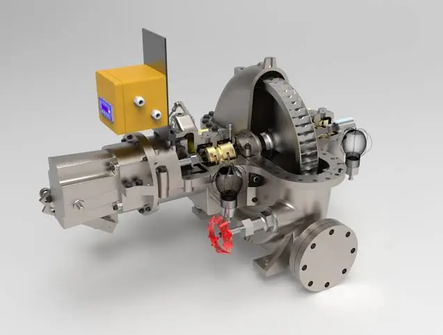
Here’s a detailed exploration of back-pressure steam turbines, presented as a long plain text. Back-pressure steam turbines, also known as non-condensing steam turbines, are a type of steam turbine where the exhaust steam exits at a pressure higher than atmospheric, typically between 2 and 20 bar, rather than being condensed into a vacuum as in condensing turbines. These turbines are designed to produce mechanical power—usually to drive a generator for electricity or to power machinery—while simultaneously supplying usable exhaust steam for industrial processes, heating, or other thermal applications. They are widely utilized in industrial settings such as pulp and paper mills, chemical plants, sugar mills, and combined heat and power (CHP) systems, with power outputs ranging from a few kilowatts to tens of megawatts. Back-pressure steam turbines are valued for their simplicity, high total energy efficiency in CHP applications, and ability to make dual use of steam as both a power source and a heat source. Let’s dive into their mechanics, design features, applications, operational details, historical context, modern relevance, advantages, and challenges.
The mechanics of a back-pressure steam turbine are based on the Rankine cycle, adapted to prioritize both mechanical power and usable exhaust steam over maximizing electrical efficiency alone. A boiler generates steam by burning fuels such as coal, natural gas, oil, or biomass (e.g., wood chips, bagasse, or rice husks), or by capturing waste heat from industrial processes—imagine exhaust from a furnace at 400-600°C or a gas engine at 300-400°C. Steam enters the turbine at pressures typically ranging from 10 to 100 bar and temperatures from 200 to 540°C, depending on the system’s scale and fuel source. This steam flows over blades mounted on a rotor—a forged steel shaft that can weigh from a few kilograms in small units to several tons in larger ones. As the steam expands—dropping from, say, 50 bar to an exhaust pressure of 5 bar—it accelerates to speeds of 300-500 meters per second, pushing the blades and spinning the rotor at speeds like 3,000 RPM for 50 Hz electrical grids, 3,600 RPM for 60 Hz, or up to 10,000 RPM in high-speed industrial designs. The rotor drives a generator to produce electricity or powers mechanical equipment such as pumps, compressors, fans, or mills through a shaft, often with a gearbox to adjust speed—for example, stepping down 10,000 RPM to 1,500 RPM for a pump. Unlike condensing turbines, which exhaust into a vacuum (0.05-0.1 bar) to extract maximum energy, back-pressure turbines release steam at a higher pressure—2 to 20 bar—determined by downstream thermal needs, such as heating a building, drying materials in a factory, or supplying steam for chemical reactions. This exhaust steam retains significant thermal energy, often 50-70% of the input, making back-pressure turbines ideal for CHP systems where the goal is to maximize total energy utilization rather than electrical output alone.
The design of back-pressure steam turbines reflects their dual-purpose role and simpler construction compared to condensing systems. They can be single-stage for small applications—say, a 50 kW unit with one set of blades extracting energy in a single pass—or multi-stage with 5 to 20 stages for larger outputs like 10 MW, allowing progressive energy extraction across multiple blade rows. Impulse designs are common, especially in smaller units—steam accelerates through nozzles into high-velocity jets that strike curved, bucket-shaped blades, spinning the rotor at high speeds like 10,000-20,000 RPM, a design rooted in Gustaf de Laval’s 1880s impulse turbine. Reaction designs, drawing from Charles Parsons’ multi-stage concept, are more typical in larger back-pressure turbines—steam expands across alternating fixed stator and moving rotor blades, spinning at 3,000-6,000 RPM for better efficiency and compatibility with standard generators. Combination designs may integrate impulse and reaction stages—impulse for the high-pressure entry (e.g., 50 bar) and reaction for the lower-pressure exhaust (e.g., 10 bar)—optimizing energy extraction in mid-sized systems. Blades vary in size—5-20 cm in high-pressure sections, up to 50 cm in low-pressure stages—made of stainless steel for durability or nickel-based alloys like Inconel for heat resistance up to 540°C, often coated with chromium or ceramic to resist corrosion and erosion from wet steam. Rotors, forged steel, are precision-balanced to handle high speeds without vibration, while casings—cast steel or alloys—contain pressures up to 100 bar, with seals like labyrinths or packing glands minimizing leakage, though sealing is less critical here than in condensing turbines since the exhaust pressure is higher than atmospheric, reducing the pressure differential that drives leaks.
Back-pressure steam turbine generators couple the turbine with an alternator or dynamo to produce electricity, scaled to the system’s needs. A 1 MW unit might generate 400 V AC for industrial machinery, while a 50 kW unit produces 230 V AC for a small facility, synchronized at 50 or 60 Hz for grid or local use. Generators are typically synchronous—rotor poles spin within stator windings—cooled by air or water to dissipate heat from 50-70% energy losses, with voltage adjustable via regulators to match loads. Boilers, producing 10 to 100 tons/hour of steam, integrate with diverse fuels—natural gas offers clean combustion with minimal emissions, biomass leverages local waste like sawdust or agricultural residues, and waste heat taps free energy from processes like steelmaking or cement production. Unlike condensing turbines, back-pressure systems eliminate the need for a condenser and associated cooling infrastructure—exhaust steam is piped directly to heat exchangers, process equipment, or heating systems, simplifying installation and maintenance compared to the complex cooling towers and vacuum pumps of condensing setups. Control systems range from manual valves and mechanical governors in basic configurations to digital controls with sensors in modern units, adjusting steam flow to balance power and heat output, with costs ranging from $10,000 for a 50 kW unit to $1-2 million for a 10 MW system, depending on size and sophistication.
Applications of back-pressure steam turbines are concentrated in industries and settings where both electrical power and thermal energy are required, making them a natural fit for CHP operations. Pulp and paper mills are a prime example—a 5 MW turbine burns wood waste from sawmill operations, producing 4 MW of electricity to run machinery like grinders and pumps, and 10 tons/hour of 5-bar steam to dry paper pulp, capitalizing on abundant biomass to offset grid costs by $1-2 million annually. Chemical plants use them for process steam—a 10 MW turbine generates 8 MW of power and 20 tons/hour of 15-bar steam for reactors, distillation columns, or heating vats, often fueled by natural gas for its consistent heat output. Sugar mills rely heavily on them with bagasse—a 3 MW turbine powers milling equipment and delivers 8 tons/hour of 10-bar steam to evaporate cane juice, using cane waste to achieve near-self-sufficiency during harvest season, reducing reliance on external energy sources. Textile factories employ smaller units—a 500 kW turbine produces 400 kW and 2 tons/hour of 3-bar steam for dyeing fabrics or heating dye vats, often coal-fired in regions where coal is cheap and accessible. District heating systems in colder climates adopt them—a 2 MW turbine generates 1.5 MW of electricity and heats a small town with 5-bar steam piped to radiators, burning local biomass like wood pellets for sustainability and cost savings. Small cogeneration plants use them for grid support—a 20 MW turbine supplies 15 MW to the grid and steam to nearby factories, fueled by oil or gas in urban settings where fuel supply is reliable. Off-grid applications benefit as well—a 50 kW turbine in a remote farm burns wood, powering tools and heating livestock barns with 2-bar steam, providing energy independence where extending the grid would cost tens of thousands of dollars per kilometer.
Efficiency in back-pressure steam turbines depends on their operational priorities, with a focus on total energy utilization rather than electrical output alone. Electrical efficiency is typically lower than that of condensing turbines—ranging from 20-30%—because the steam expansion stops at a higher exhaust pressure, leaving much of its energy as usable heat rather than converting it fully to mechanical work. A 5 MW turbine burning 20 tons/hour of steam (50 bar, 540°C) might produce 1.5 MW of electricity (25% efficiency), with 70% of the energy exiting as 10-bar steam (3.5 MW thermal equivalent), and 5-10% lost to friction, blade turbulence, and leakage. In CHP mode, total efficiency—combining power and heat—reaches 70-85%, far surpassing the 35-45% electrical efficiency of condensing systems, making them highly efficient when both outputs are utilized. For instance, a 3 MW turbine might convert 25% to electricity (750 kW), 55% to 5-bar steam (1.65 MW thermal), and lose 20% to waste heat—a stark contrast to condensing turbines, which reject 50-60% of energy as unusable heat. Losses in back-pressure turbines come from incomplete expansion (exhaust at 5-20 bar vs. 0.05 bar in condensing units), blade inefficiencies due to fewer stages compared to large turbines, and leakage (5-10% with basic seals). Multi-stage designs with 5-20 stages or superheating steam to 540°C can boost electrical efficiency to 30-35%, but lowering the exhaust pressure (e.g., to 2 bar) increases power output at the expense of usable heat, a trade-off that CHP systems carefully manage to meet thermal demands. Fuel quality significantly impacts performance—dry biomass at 4.5 kWh/kg outperforms wet biomass at 3 kWh/kg, with moisture levels above 20% reducing steam output by 30% if not pre-dried, a common challenge in biomass-heavy applications like sugar mills or sawmills.
The historical development of back-pressure steam turbines traces back to the early days of steam power, evolving from the need to utilize steam efficiently in industrial settings. Charles Parsons’ 1884 multi-stage turbine and Gustaf de Laval’s impulse design provided the foundational technology, but by the early 20th century, industries adopted back-pressure turbines for their ability to supply both power and heat, outpacing less efficient steam engines (5-10% efficiency) with turbines offering 15-25% electrical efficiency plus usable steam. Pre-World War II factories used coal-fired units to drive machinery and heat workspaces, scaling to megawatts by the 1930s as metallurgy improved—chromium steels allowed higher temperatures and pressures, increasing durability and performance. During WWII, back-pressure turbines powered small plants or military facilities—e.g., a 1 MW unit ran a factory and warmed it using rationed fuel, proving their resilience in resource-scarce conditions. Post-war, condensing turbines took over large-scale power generation due to their higher electrical efficiency, but the 1970s energy crisis revived back-pressure designs for CHP applications, particularly with the rise of biomass and waste heat as alternative fuels amid soaring oil prices. Modern units enhance this legacy—digital automation optimizes steam use, and advanced materials like nickel alloys withstand temperatures up to 540°C, though they remain a specialized tool compared to the widespread use of condensing systems in utility-scale power plants.
The modern significance of back-pressure steam turbines lies in their role in energy efficiency and sustainability, particularly in industrial and decentralized energy systems. Industrial CHP applications thrive with these turbines—a 10 MW turbine saves a factory $2-3 million annually by reusing exhaust steam for processes like drying or heating, far more cost-effective than separate power generation (30-40% efficiency) and heating systems (50-60% fuel loss), which can double operational costs. Biomass utilization is on the rise—a 5 MW turbine burns 2 tons/hour of wood waste, reducing fossil fuel dependence in rural industries like sawmills or paper plants, aligning with carbon reduction goals such as those set by international agreements like the Paris Accord. Waste heat recovery expands their reach—a 2 MW turbine uses 400°C exhaust from a steel furnace, generating power and steam without additional fuel, cutting emissions and costs by $500,000 yearly in industries with high heat output. District heating systems in Europe and North America rely on them—a 3 MW turbine heats 500 homes and powers local loads with 5-bar steam, often fueled by gas or biomass for reliability and sustainability, providing a cost-effective alternative to separate electric and heating grids. Decentralized power applications grow too—a 50-500 kW turbine serves off-grid communities or farms where grid access costs exceed $10,000 per kilometer, offering a self-sufficient energy solution. Innovations bolster their role—digital controls with real-time sensors balance power and heat output, advanced coatings handle higher temperatures, and modular designs reduce installation costs, though condensing turbines dominate in scenarios focused solely on large-scale electricity production.
The advantages of back-pressure steam turbines are numerous and context-specific, making them a compelling choice for certain applications. Their simplicity—no need for a condenser or cooling towers—reduces initial costs to $500-$1,000 per kW, compared to $1,500-$2,000/kW for condensing systems, and eliminates the maintenance burden of complex cooling infrastructure like vacuum pumps or cooling water treatment systems. High CHP efficiency (70-85%) maximizes energy utilization—a 5 MW turbine delivers 4 MW of combined electrical and thermal output, outperforming standalone generators or boilers in total energy efficiency, especially when exhaust steam is fully utilized. Fuel flexibility accommodates a wide range of local resources—wood, agricultural waste, gas, or waste heat work effectively, making them viable in diverse settings like forested regions, agricultural zones, or industrial hubs with excess heat. Their compact size fits constrained spaces—a 1 MW unit requires a 5×10-meter footprint versus 10×20 meters for a condensing setup, easing installation in factories or small plants where space is at a premium. Reliability is robust—units can run for 20-30 years with regular maintenance, operating 5,000-8,000 hours/year in harsh conditions like dusty mills or humid climates, with fewer components prone to failure compared to condensing systems. Sustainability aligns with green initiatives—biomass-driven units achieve near carbon neutrality when paired with regrowth cycles, and waste heat recovery minimizes fuel use, supporting eco-friendly operations in industries aiming to reduce their carbon footprint.
Challenges, however, limit their broader adoption and must be carefully considered. Their lower electrical efficiency (20-30%) restricts power output compared to condensing turbines—a 5 MW turbine yields 1.5 MW of electricity versus 2 MW from a condensing turbine with the same steam input, requiring more fuel (e.g., 2 tons/hour of wood versus 1.5 tons) to achieve equivalent electrical generation, which can increase operational costs if heat isn’t fully utilized. The trade-off between exhaust pressure and power constrains design flexibility—higher exhaust pressures (10-20 bar) preserve more heat for thermal use but reduce electrical yield, while lower pressures (2-5 bar) boost power at the cost of thermal utility, requiring precise calibration to meet specific site needs. Maintenance needs—blade wear from wet steam, seal leakage, and boiler scaling—cost $10,000-$50,000 annually for a 5 MW unit, with downtime interrupting power or heat supply, a significant concern in continuous operations like chemical plants or paper mills. Emissions from biomass fuels—particulates at 50-200 mg/m³ and CO—require filters or scrubbers costing $10,000-$50,000 to meet stringent regulations like the U.S. EPA’s 25 mg/m³ limit or the EU’s 20 mg/m³ standard, adding expense and complexity to biomass-driven systems. Initial costs, while lower than condensing systems, remain significant—$500,000 for a 1 MW unit can’t compete with solar’s $1-2/W for small-scale power generation, making them less attractive for pure electricity needs. Fuel logistics pose additional risks—wet biomass (e.g., 50% moisture) or inconsistent waste heat reduces steam quality, cutting output by 20-30% if not managed with drying systems or heat buffers, a practical challenge in regions with variable fuel availability.
Examples showcase their practical impact across various scales and industries. A 1 MW back-pressure turbine in a textile plant burns coal, producing 800 kW of electricity and 3 tons/hour of 5-bar steam for dyeing processes, saving $200,000 annually on energy bills with a $400,000 setup cost, paying back in two years. A 10 MW turbine in a paper mill uses wood waste, generating 8 MW of power and 20 tons/hour of 10-bar steam for drying pulp, reducing operational costs by $2 million yearly against a $2 million investment, leveraging free biomass from mill operations. A 50 kW off-grid turbine in a rural farm burns logs, powering tools with 40 kW and heating a barn with 2-bar steam, costing $10,000 to install but saving $5,000 annually over diesel generators, ideal where fuelwood is abundant and grid access is impractical.
Back-pressure steam turbines excel in environments where power and heat are both valuable, offering a streamlined, efficient solution for industries, small plants, and off-grid sites. Their evolution—from early 20th-century industrial applications to modern CHP systems—reflects a focus on resource efficiency and adaptability, ensuring they remain a relevant and practical choice in a world increasingly balancing energy needs with sustainability goals. Their ability to turn steam into a dual-purpose resource keeps them a vital tool in the energy landscape, particularly where local fuels or waste heat can be harnessed effectively.
Here’s a continued exploration of back-pressure steam turbines, presented as a detailed plain text that builds on the previous discussion with deeper insights and expanded perspectives. Back-pressure steam turbines, also referred to as non-condensing steam turbines, are engineered to generate mechanical power—typically for electricity production or driving machinery—while exhausting steam at a pressure above atmospheric levels, usually between 2 and 20 bar, making the exhaust steam usable for industrial processes, heating, or other thermal applications. Unlike condensing turbines, which exhaust into a vacuum to maximize electrical output, back-pressure turbines prioritize a balance between power generation and thermal energy delivery, making them ideal for combined heat and power (CHP) systems and industrial settings like sugar mills, pulp and paper plants, and chemical facilities. With capacities ranging from a few kilowatts to tens of megawatts, they offer simplicity, high total energy efficiency when paired with heat use, and versatility with various fuel sources. Let’s delve further into their mechanics, design intricacies, applications, operational specifics, historical evolution, modern significance, advantages, and challenges.
The mechanics of a back-pressure steam turbine follow the Rankine cycle, tailored to provide both mechanical work and usable exhaust steam rather than focusing solely on electrical efficiency. A boiler produces steam by combusting fuels such as coal, natural gas, oil, or biomass (e.g., wood pellets, sawdust, or agricultural residues like corn stalks), or by capturing waste heat from sources like industrial exhausts at 400-600°C or engine tailpipes at 300-400°C. Steam enters the turbine at pressures typically between 10 and 100 bar and temperatures from 200 to 540°C, depending on the system’s size and fuel quality. This steam flows over blades mounted on a rotor—a forged steel shaft that ranges from a few kilograms in small units to several tons in larger ones. As the steam expands—say, from 50 bar to an exhaust pressure of 5 bar—it accelerates to speeds of 300-500 meters per second, driving the blades and spinning the rotor at speeds like 3,000 RPM for 50 Hz grids, 3,600 RPM for 60 Hz, or up to 10,000 RPM in high-speed configurations. The rotor powers a generator to produce electricity or drives machinery such as pumps, fans, compressors, or mills via a shaft, often with a gearbox to adjust speed—for example, reducing 10,000 RPM to 1,500 RPM for a pump. Unlike condensing turbines, which exhaust into a vacuum (0.05-0.1 bar) to extract maximum energy, back-pressure turbines release steam at a higher pressure—2 to 20 bar—set by downstream thermal requirements, such as heating a factory, drying lumber, or supplying steam for chemical distillation. This exhaust steam retains substantial thermal energy, often 50-70% of the input, making back-pressure turbines highly effective in CHP setups where the total energy utilization of both power and heat is the primary objective.
The design of back-pressure steam turbines is practical, emphasizing dual-purpose energy production and reduced complexity compared to condensing systems. They can be single-stage for small-scale use—such as a 50 kW unit with one blade set extracting energy in a single pass—or multi-stage with 5 to 20 stages for larger capacities like 10 MW, allowing gradual energy extraction across multiple blade rows. Impulse designs are prevalent in smaller units—steam accelerates through nozzles into high-velocity jets that strike curved, bucket-shaped blades, spinning the rotor at high speeds like 10,000-20,000 RPM, echoing Gustaf de Laval’s 1880s impulse turbine. Reaction designs, inspired by Charles Parsons’ multi-stage approach, are more common in larger back-pressure turbines—steam expands across alternating fixed stator and moving rotor blades, spinning at 3,000-6,000 RPM for improved efficiency and compatibility with standard generators. Combination designs may blend impulse and reaction stages—impulse for the high-pressure entry (e.g., 50 bar) and reaction for the lower-pressure exhaust (e.g., 10 bar)—optimizing performance in mid-sized systems. Blades are sized for the pressure range—5-20 cm in high-pressure sections, up to 50 cm in low-pressure stages—crafted from stainless steel for cost-effectiveness and corrosion resistance or nickel-based alloys like Inconel for heat tolerance up to 540°C, often coated with chromium or ceramic to combat erosion from wet steam. Rotors, forged steel, are precision-balanced to handle high speeds without vibration, while casings—cast steel or alloys—contain pressures up to 100 bar, with seals like labyrinths or packing glands minimizing leakage, though sealing is less critical here than in condensing turbines due to the higher exhaust pressure reducing the pressure differential that drives leaks.
Back-pressure steam turbine generators pair the turbine with a synchronous generator or alternator to produce electricity, tailored to the system’s scale. A 1 MW unit might generate 400 V AC for industrial machinery, while a 50 kW unit produces 230 V AC for smaller loads, synchronized at 50 or 60 Hz for grid or local use. Generators feature rotor poles spinning within stator windings, cooled by air in smaller units or water in larger ones to dissipate heat from 50-70% energy losses, with voltage regulators adjusting output to match demand. Boilers, producing 10 to 100 tons/hour of steam, integrate with a variety of fuels—natural gas provides clean, efficient combustion, biomass utilizes local waste like wood chips or straw, and waste heat taps free energy from processes such as glass manufacturing or cement kilns. Unlike condensing turbines, back-pressure systems skip the condenser and cooling towers—exhaust steam is piped directly to heat exchangers, process equipment, or heating systems, simplifying the setup and reducing the footprint and maintenance compared to the extensive cooling infrastructure of condensing turbines. Control systems vary—manual valves and mechanical governors suffice in basic setups, while modern units use digital controls with sensors to adjust steam flow, optimizing the balance between power and heat output, with costs ranging from $10,000 for a 50 kW unit to $1-2 million for a 10 MW system, depending on capacity and features.
Applications of back-pressure steam turbines are centered in industries and settings where both electrical power and thermal energy are in demand, making them a cornerstone of CHP operations. Pulp and paper mills frequently use them—a 5 MW turbine burns wood waste from sawmill operations, producing 4 MW of electricity to power grinders and conveyors, and 10 tons/hour of 5-bar steam to dry paper pulp, leveraging abundant biomass to save $1-2 million annually on grid electricity and heating costs. Chemical plants rely on them for process steam—a 10 MW turbine generates 8 MW of power and 20 tons/hour of 15-bar steam for reactors, distillation units, or heating, often fueled by natural gas for its reliability and low emissions. Sugar mills depend on them with bagasse—a 3 MW turbine powers milling equipment and supplies 8 tons/hour of 10-bar steam to evaporate cane juice, using cane waste to achieve near energy self-sufficiency during harvest season, minimizing reliance on external fuel sources. Textile factories use smaller units—a 500 kW turbine produces 400 kW and 2 tons/hour of 3-bar steam for dyeing or heating dye vats, often coal-fired in regions with affordable coal supplies. District heating systems in colder climates adopt them—a 2 MW turbine generates 1.5 MW of electricity and heats a small town with 5-bar steam piped to radiators, burning local biomass like wood pellets for cost-effective sustainability. Small cogeneration plants use them for grid support—a 20 MW turbine supplies 15 MW to the grid and steam to nearby factories, fueled by oil or gas in urban areas with reliable fuel access. Off-grid applications benefit too—a 50 kW turbine in a remote farm burns wood, powering tools and heating barns with 2-bar steam, offering energy independence where grid extension costs are prohibitive.
Efficiency in back-pressure steam turbines hinges on their dual-purpose operation, with a focus on total energy utilization rather than electrical output alone. Electrical efficiency is typically 20-30%, lower than condensing turbines (35-45%) because the steam expansion stops at a higher exhaust pressure, preserving energy for thermal use rather than converting it fully to mechanical work. A 5 MW turbine burning 20 tons/hour of steam (50 bar, 540°C) might produce 1.5 MW of electricity (25% efficiency), with 70% of the energy exiting as 10-bar steam (3.5 MW thermal equivalent), and 5-10% lost to friction, blade turbulence, and leakage. In CHP mode, total efficiency—combining power and heat—reaches 70-85%, significantly outperforming the 35-45% electrical efficiency of condensing systems when exhaust steam is fully utilized. For example, a 3 MW turbine might convert 25% to electricity (750 kW), 55% to 5-bar steam (1.65 MW thermal), and lose 20% to waste heat—a stark contrast to condensing turbines, which discard 50-60% of energy as unusable heat. Losses in back-pressure turbines arise from incomplete expansion (exhaust at 5-20 bar vs. 0.05 bar in condensing units), blade inefficiencies due to fewer stages than large condensing turbines, and leakage (5-10% with basic seals). Multi-stage designs with 5-20 stages or superheating steam to 540°C can increase electrical efficiency to 30-35%, but lowering the exhaust pressure (e.g., to 2 bar) boosts power at the expense of usable heat, a trade-off that CHP systems calibrate to match thermal demands. Fuel quality plays a critical role—dry biomass at 4.5 kWh/kg outperforms wet biomass at 3 kWh/kg, with moisture levels above 20% reducing steam output by 30% if not pre-dried, a frequent challenge in biomass-driven systems like sugar mills or rural installations.
The historical evolution of back-pressure steam turbines traces back to the early 20th century, driven by industrial needs for efficient steam use. Charles Parsons’ 1884 multi-stage turbine and Gustaf de Laval’s impulse design laid the groundwork, but by the 1920s, industries adopted back-pressure turbines for their ability to supply both power and heat, surpassing steam engines (5-10% efficiency) with turbines offering 15-25% electrical efficiency plus usable steam. Pre-World War II factories used coal-fired units to drive machinery and heat workspaces, scaling to megawatts by the 1930s as metallurgy advanced—chromium steels enabled higher temperatures and pressures, improving durability and output. During WWII, back-pressure turbines powered small plants or military facilities—e.g., a 1 MW unit ran a factory and heated it on limited fuel, showcasing their adaptability. Post-war, condensing turbines dominated large-scale power generation due to their higher electrical efficiency, but the 1970s energy crisis revived back-pressure designs for CHP, particularly with biomass and waste heat as oil prices soared, prompting a shift toward energy conservation. Modern units build on this legacy—digital automation enhances steam management, and materials like nickel alloys withstand 540°C, refining their role in industrial and sustainable energy systems, though they remain niche compared to condensing turbines in utility-scale applications.
The modern significance of back-pressure steam turbines lies in their efficiency and adaptability in industrial and decentralized energy contexts. Industrial CHP systems benefit greatly—a 10 MW turbine saves a factory $2-3 million annually by reusing exhaust steam for processes like drying or heating, far more economical than separate power generation (30-40% efficiency) and heating systems (50-60% fuel loss), which can inflate costs by 50-100%. Biomass utilization grows—a 5 MW turbine burns 2 tons/hour of wood waste, reducing fossil fuel reliance in rural industries like sawmills or paper plants, aligning with carbon neutrality goals and policies like the EU’s Green Deal. Waste heat recovery expands their scope—a 2 MW turbine uses 400°C exhaust from a glass furnace, generating power and steam without additional fuel, cutting emissions and costs by $500,000 yearly in heat-intensive sectors. District heating in colder regions leans on them—a 3 MW turbine heats 500 homes and powers local loads with 5-bar steam, often fueled by gas or biomass for reliability and eco-friendliness, offering a cost-effective alternative to separate grids. Decentralized power applications rise too—a 50-500 kW turbine serves off-grid communities or farms where grid extension costs exceed $10,000 per kilometer, providing self-sufficient energy. Innovations enhance their utility—digital controls with real-time sensors optimize power and heat balance, advanced coatings handle higher temperatures, and modular designs cut installation costs, though condensing turbines lead in pure power generation scenarios.
The advantages of back-pressure steam turbines are compelling for their specific applications. Their simplicity—no condenser or cooling towers—lowers initial costs to $500-$1,000 per kW versus $1,500-$2,000/kW for condensing systems, and reduces maintenance by avoiding complex cooling infrastructure like vacuum pumps or water treatment plants. High CHP efficiency (70-85%) maximizes energy use—a 5 MW turbine delivers 4 MW of combined electrical and thermal output, outperforming standalone generators or boilers when exhaust steam is fully utilized. Fuel flexibility accommodates diverse resources—wood, agricultural waste, gas, or waste heat work seamlessly, making them viable in forested areas, farming regions, or industrial zones with excess heat. Their compact size suits tight spaces—a 1 MW unit requires a 5×10-meter footprint versus 10×20 meters for a condensing setup, easing installation in factories or small plants. Reliability is strong—units run 20-30 years with regular maintenance, operating 5,000-8,000 hours/year in tough conditions like dusty mills or humid climates, with fewer failure-prone components than condensing systems. Sustainability aligns with green trends—biomass units offset CO2 with regrowth, and waste heat recovery cuts fuel use, appealing to eco-conscious operations.
Challenges limit their broader adoption. Lower electrical efficiency (20-30%) caps power output—a 5 MW turbine yields 1.5 MW versus 2 MW from a condensing turbine with the same input, needing more fuel (e.g., 2 tons/hour of wood vs. 1.5 tons) for equivalent electricity, raising costs if heat isn’t fully used. Exhaust pressure trade-offs constrain design—higher pressures (10-20 bar) preserve heat but reduce power, while lower pressures (2-5 bar) boost power at heat’s expense, requiring precise tuning. Maintenance—blade wear, seal leaks, boiler scaling—costs $10,000-$50,000 yearly for a 5 MW unit, with downtime disrupting output, a concern in continuous processes. Biomass emissions (50-200 mg/m³ particulates) need filters ($10,000-$50,000) to meet limits like the EU’s 20 mg/m³, adding cost. Initial costs—$500,000 for 1 MW—lag solar ($1-2/W) for small-scale power. Fuel inconsistency—wet biomass or variable heat—cuts output by 20-30% without mitigation.
Examples highlight their value. A 1 MW textile turbine burns coal, produces 800 kW and 3 tons/hour of 5-bar steam, saving $200,000 yearly. A 10 MW paper mill turbine uses wood waste, generates 8 MW and 20 tons/hour of 10-bar steam, saving $2 million. A 50 kW farm turbine burns logs, powers 40 kW and heats with 2-bar steam, saving $5,000 annually.
Back-pressure steam turbines shine where power and heat converge, their efficiency and adaptability making them vital for industries and CHP, blending steam’s legacy with modern energy needs.
EMS Power Machines
We design, manufacture and assembly Power Machines such as – diesel generators, electric motors, vibration motors, pumps, steam engines and steam turbines
EMS Power Machines is a global power engineering company, one of the five world leaders in the industry in terms of installed equipment. The companies included in the company have been operating in the energy market for more than 60 years.
EMS Power Machines manufactures steam turbines, gas turbines, hydroelectric turbines, generators, and other power equipment for thermal, nuclear, and hydroelectric power plants, as well as for various industries, transport, and marine energy.
EMS Power Machines is a major player in the global power industry, and its equipment is used in power plants all over the world. The company has a strong track record of innovation, and it is constantly developing new and improved technologies.
Here are some examples of Power Machines’ products and services:
- Steam turbines for thermal and nuclear power plants
- Gas turbines for combined cycle power plants and industrial applications
- Hydroelectric turbines for hydroelectric power plants
- Generators for all types of power plants
- Boilers for thermal power plants
- Condensers for thermal power plants
- Reheaters for thermal power plants
- Air preheaters for thermal power plants
- Feedwater pumps for thermal power plants
- Control systems for power plants
- Maintenance and repair services for power plants
EMS Power Machines is committed to providing its customers with high-quality products and services. The company has a strong reputation for reliability and innovation. Power Machines is a leading provider of power equipment and services, and it plays a vital role in the global power industry.
EMS Power Machines, which began in 1961 as a small factory of electric motors, has become a leading global supplier of electronic products for different segments. The search for excellence has resulted in the diversification of the business, adding to the electric motors products which provide from power generation to more efficient means of use.