Residential Steam Turbine: Steam engines have played a pivotal role in the industrial revolution and continue to capture the imagination of those interested in mechanical engineering, DIY projects, and alternative energy sources. The idea of building a homemade steam engine generator may sound ambitious, but with the right tools, knowledge, and materials, it is possible to create a working steam engine that can generate electricity or mechanical power for various uses. In this comprehensive guide, we will explore what it takes to build a homemade steam engine generator, the principles behind its operation, the types of steam engines suitable for such projects, and practical considerations for design and safety.
The Basics of Steam Power
Steam engines convert the energy stored in steam into mechanical energy through a process called thermodynamics. The basic concept involves heating water to produce steam, which is then used to move pistons or turbines. These moving parts generate kinetic energy that can be harnessed to perform work, such as turning a generator to produce electricity.
Steam engines are classified into two main types: reciprocating steam engines and steam turbines. Reciprocating engines use a piston that moves back and forth within a cylinder, while steam turbines use rotating blades or vanes to convert steam energy into mechanical motion. For homemade generators, reciprocating engines are often more accessible, though steam turbines can also be adapted for DIY projects with the right skills and tools.
Key Components of a Homemade Steam Engine Generator
Creating a homemade steam engine generator requires several critical components, each with a specific function to ensure the system operates effectively and safely. These include:
Boiler
The boiler is responsible for heating water to produce steam. In most DIY projects, the boiler can be fabricated from a pressure-rated vessel such as a repurposed propane tank, old steam heater, or fabricated steel drum. It must be designed to withstand high pressures and temperatures, and safety features like pressure release valves and water level gauges are essential to prevent accidents.
Boilers can be powered by various fuels, such as wood, coal, propane, or natural gas, depending on the availability of resources and personal preference. The choice of fuel also affects the design of the burner and heat exchanger system.
Piston and Cylinder
In reciprocating steam engines, the piston and cylinder are the main moving parts. Steam is admitted into the cylinder, where it expands and pushes the piston, which is connected to a crankshaft or flywheel. The linear motion of the piston is converted into rotational motion that can drive a generator.
The cylinder must be machined with precision to ensure an airtight seal between the piston and the cylinder walls, allowing for efficient energy transfer. The materials used for the piston and cylinder are typically cast iron or steel due to their durability and resistance to high temperatures and pressures.
Flywheel
A flywheel is attached to the crankshaft to store energy and smooth out the engine’s power delivery. In steam engines, the power output is not continuous due to the back-and-forth motion of the piston. The flywheel stores energy during the power stroke and releases it during the non-power portions of the cycle, helping to maintain consistent motion.
Generator
To convert mechanical energy into electrical energy, the engine must be connected to a generator. This can be done using a belt drive, gear system, or direct coupling, depending on the engine’s design. The generator should be matched to the power output of the engine to ensure optimal efficiency. Typically, small-scale steam engines produce enough power to drive low-wattage generators suitable for residential or small-scale applications.
Condenser
In some systems, a condenser is used to cool the steam after it has passed through the engine. This allows the steam to condense back into water, which can be returned to the boiler. This process increases the system’s efficiency by recycling the water and reducing fuel consumption.
Building the Boiler
One of the most crucial and potentially dangerous aspects of a homemade steam engine generator is the boiler. It needs to be built to strict specifications to handle the high pressure and temperature of steam safely. Here’s a step-by-step guide to constructing a simple boiler for a homemade generator:
Choosing Materials
For small steam engines, repurposing steel or iron containers, such as old air tanks or propane tanks, is common. However, you must ensure that the vessel is structurally sound and rated for the pressures it will experience. It’s also essential to include safety features like pressure relief valves and water gauges.
Heating System
The heat source for your boiler will depend on available fuels. Wood-burning stoves are often used in homemade boilers for their simplicity and low cost. However, propane burners can offer more consistent and controllable heat. The design must ensure an even distribution of heat across the boiler to avoid hotspots that could weaken the structure.
Pressure and Safety Controls
Pressure control is critical in any boiler system. A high-quality pressure gauge is required to monitor the pressure within the boiler. When pressure reaches unsafe levels, a pressure relief valve should automatically vent steam to prevent the boiler from exploding. Additionally, incorporating a water level gauge ensures that the boiler doesn’t run dry, which can cause catastrophic overheating.
Water Supply
For continuous operation, the boiler needs a reliable water supply. A feedwater pump can be used to replenish the water as steam is generated and consumed. In a DIY setup, this can be a simple hand-operated pump or a more sophisticated automatic system driven by the engine itself.
Assembling the Engine
Once the boiler is constructed and functional, the next step is to build the engine. Most DIY steam engines use a single-cylinder, reciprocating design due to its simplicity and ease of construction. Here’s a general process for assembling the engine:
Cylinder and Piston Fabrication
The cylinder is the chamber where the steam expands and moves the piston. It needs to be machined with high precision to ensure a good seal and minimal friction. The piston should fit snugly within the cylinder but move smoothly without binding.
To achieve this, you can purchase pre-machined parts from industrial suppliers or machine them yourself if you have access to a lathe or milling machine. Cast iron is the material of choice for both the cylinder and the piston due to its thermal properties and resistance to wear.
Valve Timing
In steam engines, controlling the admission and exhaust of steam into the cylinder is crucial. This is done using valve systems such as slide valves or poppet valves. Proper valve timing ensures that steam enters the cylinder at the correct point in the piston’s cycle and is expelled efficiently after it has done its work.
This step often requires careful adjustment to balance performance and efficiency. In a homemade engine, you can use a simple slide valve mechanism, which is easy to fabricate and maintain.
Flywheel and Crankshaft
The flywheel helps to store energy and stabilize the engine’s output, while the crankshaft converts the reciprocating motion of the piston into rotary motion. These components should be mounted on bearings to reduce friction and wear.
In a homemade setup, you can use a variety of repurposed materials for the flywheel, such as automotive parts, cast iron wheels, or even custom-made components. The crankshaft can be fabricated from steel rods and turned to precise dimensions on a lathe.
Power Generation and Applications
Once the engine is operational, the next step is to connect it to a generator. Most small-scale steam engines are capable of generating enough mechanical energy to power a generator rated at a few hundred watts to a few kilowatts. Here’s how to make the most of your homemade steam engine generator:
Connecting the Generator
The most straightforward way to connect the engine to the generator is through a belt or gear drive. This allows the generator to spin at a speed that matches the engine’s output. Be sure to align the pulleys or gears properly to avoid excessive wear or energy loss.
Matching Load and Power Output
It’s essential to match the power output of your engine with the electrical load you’re powering. Overloading the generator can cause it to overheat or fail. Conversely, running the engine with too light a load can result in wasted energy. You can use a power regulator or inverter to manage the energy produced by the generator and convert it into usable electricity.
Applications
Homemade steam engine generators are often used for off-grid power generation, backup power, or as part of a renewable energy system. They can power small tools, lights, or charge batteries for use during blackouts or in remote locations.
Safety Considerations
Building a homemade steam engine generator can be rewarding but comes with inherent risks. Steam at high pressure is dangerous, and if not properly managed, it can cause severe injury or damage. Key safety practices include:
- Pressure Testing: Ensure that all components, especially the boiler, are pressure tested to at least twice the operating pressure before use.
- Regular Inspections: Check for leaks, wear, and corrosion regularly. Steam leaks can be invisible but extremely hot and harmful.
- Proper Ventilation: If using solid fuels like wood or coal, make sure the area is well-ventilated to prevent the buildup of carbon monoxide.
- Emergency Shutoff: Design the system with an easy way to shut it down in case of an emergency.
Conclusion
Building a homemade steam engine generator is a challenging yet achievable project for those with a passion for mechanical engineering and alternative energy. While there are many technical hurdles to overcome, the result can be a functional generator capable of providing off-grid power for small applications. The key to success lies in careful planning, precision in construction, and a strong commitment to safety throughout the process.
25 HP Steam Engines
Steam engines, once the cornerstone of industrialization, remain a fascinating subject for those interested in mechanical engineering, historical technology, and alternative power generation. A 25-horsepower (HP) steam engine falls into a category of moderate power output and is often used in industrial, agricultural, and even hobbyist applications. While the advent of internal combustion engines and electric motors has replaced steam engines in most modern contexts, 25 HP steam engines are still relevant in specialized settings, as well as for educational and demonstration purposes.
In this detailed overview, we will explore the mechanics, history, applications, and practical considerations of 25 HP steam engines. We’ll discuss how they work, their performance characteristics, design principles, and their place in today’s world of technology. Additionally, we’ll look into the processes involved in operating and maintaining a steam engine of this capacity, as well as its potential uses in both historical and modern contexts.
Overview of Steam Engines
Steam engines work on a fundamental principle: converting heat energy from steam into mechanical energy. Steam is produced in a boiler by heating water, and the resulting steam is directed into a cylinder where it expands, moving a piston or turning a turbine. In a reciprocating steam engine, the back-and-forth motion of the piston is converted into rotational motion via a crankshaft, which can then be used to drive machinery or generate electricity.
The power output of a steam engine is measured in horsepower (HP), a unit of power that represents the ability to do work. One horsepower is equivalent to about 746 watts of power. A 25 HP steam engine, therefore, has the capacity to generate about 18.65 kilowatts of mechanical power, which is significant for small industrial applications, vehicle propulsion, or generating electricity in off-grid situations.
Historical Context
The development of steam engines dates back to the 17th century, with early designs being developed by inventors such as Thomas Savery and Thomas Newcomen. However, it was James Watt’s improvements in the 18th century that made steam engines practical for widespread use. Watt’s engines were more efficient and powerful, making them suitable for driving machinery in factories, mills, and mines.
The 25 HP steam engine emerged as a workhorse during the Industrial Revolution, providing reliable power for various industries. It was particularly common in manufacturing settings, where it could drive mechanical systems such as belt-driven machines, pumps, and locomotives. In agriculture, steam engines of this size were used to power threshing machines, sawmills, and irrigation pumps.
Despite being largely replaced by internal combustion engines and electric motors in the 20th century, steam engines still find niche applications. For example, they are used in vintage steam locomotives, marine vessels, and industrial heritage sites. Their simplicity, durability, and ability to use various fuels make them appealing in some off-grid or remote settings where modern engines may not be practical.
How a 25 HP Steam Engine Works
A 25 HP steam engine operates on the same basic principles as other steam engines, but with specific design considerations that make it efficient at producing a moderate amount of power. Here’s a closer look at the main components and how they work together:
3.1. Boiler
The boiler is where water is heated to produce steam. It is typically a pressure vessel made from steel or cast iron, capable of withstanding high temperatures and pressures. For a 25 HP engine, the boiler must be large enough to produce sufficient steam volume and pressure to maintain consistent power output. Boilers are often fired by coal, wood, oil, or gas, though some systems may use alternative fuels like biomass or waste products.
Boilers for 25 HP steam engines often incorporate safety features such as pressure relief valves, water level gauges, and blow-off valves to manage pressure and prevent accidents. Maintaining proper water levels is critical because the boiler can overheat and become damaged if it runs dry.
3.2. Cylinder and Piston
The cylinder is the heart of the reciprocating steam engine, where steam expands to push a piston. In a 25 HP engine, the cylinder is usually made from cast iron or steel, and the piston is machined to fit tightly within it. Steam is admitted to the cylinder via a valve system, and as it expands, it pushes the piston, which moves a connecting rod to turn a crankshaft.
The reciprocating motion of the piston is what generates mechanical energy. As the piston moves back and forth, it turns the crankshaft, which can be used to power a variety of machines or to drive a generator for electrical output.
3.3. Flywheel
A flywheel is attached to the crankshaft to store energy and smooth out the power delivery. Steam engines, particularly those with reciprocating pistons, tend to produce power in pulses due to the cyclical nature of the steam admission and exhaust. The flywheel helps to balance this by storing kinetic energy during the power stroke and releasing it during the non-power portions of the cycle.
For a 25 HP steam engine, the flywheel must be robust enough to handle the forces generated by the engine without excessive vibration. Typically, flywheels are made of cast iron or steel and are carefully balanced to ensure smooth operation.
3.4. Governor
A governor is a device that controls the speed of the engine by regulating the steam supply. In a steam engine, the governor works by sensing the engine’s speed and adjusting the amount of steam admitted to the cylinder. This ensures that the engine does not overspeed or underperform, maintaining a consistent level of power output.
Governors for 25 HP engines are typically centrifugal types, which use spinning weights to control a valve that adjusts the steam flow. These governors are mechanical and simple, making them reliable in a wide range of operating conditions.
3.5. Exhaust and Condenser
After the steam has done its work in the cylinder, it must be expelled to make way for the next cycle. In many systems, the steam is simply exhausted into the atmosphere, but for greater efficiency, some systems use a condenser. A condenser cools the exhaust steam, turning it back into water so it can be returned to the boiler.
Condensers are not always necessary for a 25 HP engine, especially in mobile applications like tractors or small locomotives. However, in stationary applications, using a condenser can improve efficiency by recycling water and reducing fuel consumption.
Applications of 25 HP Steam Engines
Although steam engines have largely been replaced by more modern technologies, 25 HP steam engines still have a variety of applications today. These engines are prized for their simplicity, durability, and ability to run on diverse fuel sources. Here are some common applications:
4.1. Industrial Heritage and Preservation
Many historical industrial sites, museums, and heritage railways operate 25 HP steam engines as part of their efforts to preserve and demonstrate industrial technology. These engines are often used to power belt-driven machinery in workshops, mills, and factories, showcasing how steam power was harnessed during the 19th and early 20th centuries.
4.2. Agriculture
In some regions, steam engines are still used in agriculture for tasks such as powering threshing machines, sawmills, and irrigation pumps. In particular, 25 HP engines are popular at agricultural shows and steam rallies, where they are used to demonstrate traditional farming techniques.
4.3. Off-Grid Power Generation
For off-grid applications, particularly in remote areas or locations with unreliable power grids, steam engines can be an attractive alternative to internal combustion engines. A 25 HP steam engine can generate enough power to run small workshops, farms, or remote industrial operations. Steam engines can also use locally sourced fuels like wood or biomass, making them a renewable energy option in some cases.
4.4. Marine and Locomotive Use
Historically, 25 HP steam engines were used to power small marine vessels and locomotives. While this is less common today, some vintage boats and railways still operate steam-powered vessels and locomotives as part of heritage projects. In these cases, the engines are typically well-maintained and carefully operated by enthusiasts or professionals.
4.5. Hobbyists and Steam Enthusiasts
For many steam enthusiasts and hobbyists, the 25 HP engine is an ideal size for building and operating scale models, small locomotives, or stationary engines. These engines are large enough to demonstrate the principles of steam power effectively, but not so large that they require industrial-scale facilities or tools to construct and maintain.
Operation and Maintenance
Operating a 25 HP steam engine requires knowledge of steam engineering principles and a commitment to regular maintenance. Unlike modern engines, steam engines require hands-on management of fuel, water, and pressure to operate efficiently. Here are some of the key operational and maintenance considerations:
5.1. Fuel Management
Steam engines consume fuel to generate heat in the boiler, which in turn produces steam. Depending on the type of boiler and the available resources, the engine may run on wood, coal, oil, or gas. Fuel management is crucial for maintaining steady steam production, and operators must monitor fuel levels and adjust the fire to ensure consistent heat.
5.2. Water Supply
The boiler requires a constant supply of water to generate steam. Running the boiler dry can cause overheating and damage, so it is important to monitor water levels closely. In larger systems, feedwater pumps are used to automatically replenish water, but smaller setups may require manual intervention.
5.3. Lubrication
Like all mechanical systems, steam engines require regular lubrication to reduce friction and prevent wear on moving parts. Special steam oil is used to lubricate the cylinder and valve surfaces, which are exposed to high temperatures and steam.
5.4. Pressure Management
Monitoring and managing pressure is critical for safe and efficient operation. Operators must ensure that the boiler pressure stays within safe limits, using pressure gauges and safety valves to prevent overpressure situations. Regular inspection of these components is essential for maintaining safety.
5.5. Regular Inspections
Steam engines must be inspected regularly for signs of wear, corrosion, or other issues. Boilers, in particular, need to be inspected for leaks, cracks, or weak spots that could lead to dangerous failures. Many regions require steam engines to undergo safety inspections and certification before they can be operated.
Advantages and Disadvantages
6.1. Advantages
- Versatility: A 25 HP steam engine can be used for a variety of applications, from industrial use to hobbyist projects.
- Fuel Flexibility: Steam engines can run on a wide range of fuels, including renewable sources like wood and biomass.
- Durability: Well-built steam engines can last for decades with proper maintenance, making them a long-term investment.
- Simplicity: Steam engines are relatively simple in design, especially compared to internal combustion engines, which makes them easier to repair and maintain for skilled operators.
6.2. Disadvantages
- Inefficiency: Compared to modern engines, steam engines are less efficient in converting fuel to power, especially without a condenser.
- Maintenance: Steam engines require regular maintenance and careful operation, which can be time-consuming.
- Size and Weight: Steam engines are typically larger and heavier than equivalent internal combustion engines, making them less suitable for mobile applications.
- Fuel Consumption: While steam engines can use a wide range of fuels, they typically consume more fuel per unit of power generated than modern engines.
7. Conclusion
The 25 HP steam engine occupies a unique place in the history and modern application of steam power. While largely replaced by more efficient technologies in most sectors, it remains an important tool for industrial heritage preservation, off-grid power generation, and enthusiast communities. With their versatility, durability, and ability to run on a variety of fuels, 25 HP steam engines continue to provide a tangible connection to the technological innovations of the past, while also offering practical benefits in certain niche applications.
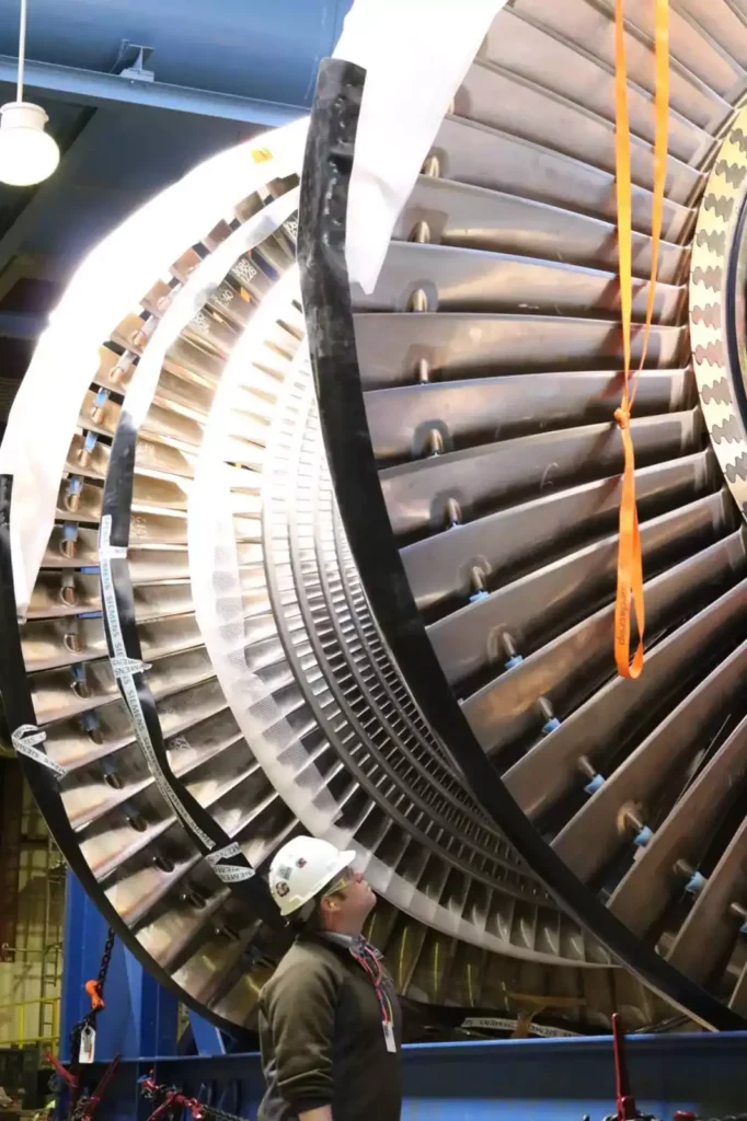
Steam Turbine Manufacturing
Steam turbines are integral components in a variety of industries, including power generation, industrial processing, and transportation. Unlike steam engines, which use pistons to convert steam into mechanical energy, steam turbines operate by using the high-pressure, high-velocity steam to spin a rotor with attached blades, thus producing rotational motion. Steam turbines are favored for their efficiency and reliability in converting thermal energy into mechanical work.
The manufacturing of steam turbines is a complex process that requires precision engineering, advanced materials, and rigorous quality control. In this section, we will explore the process of steam turbine manufacturing in detail, from design and material selection to the assembly and testing of these powerful machines. We’ll examine the key steps involved, the challenges faced by manufacturers, and the technological advancements that continue to shape the production of steam turbines.
1. Overview of Steam Turbines
Steam turbines are machines designed to convert the energy of steam into mechanical motion, typically to drive generators that produce electricity. The basic principle behind a steam turbine involves directing high-velocity steam onto blades mounted on a rotor. As the steam strikes the blades, it causes the rotor to spin, and this rotational energy is then harnessed for various industrial applications.
There are several types of steam turbines, including:
- Impulse Turbines: In these turbines, steam is directed at high speed onto the blades, causing the rotor to spin. The pressure of the steam is mostly reduced in the nozzles, and the turbine blades experience a “push” from the steam.
- Reaction Turbines: In these turbines, steam expands and changes pressure as it moves through the blades. The blades are shaped to create both lift and drag forces, which spin the rotor.
- Mixed Types: Many modern turbines use a combination of impulse and reaction stages to optimize efficiency.
Turbines are widely used in power plants (both fossil fuel and nuclear), ships, aircraft, and various industrial processes requiring high-power mechanical work.
2. Design Phase of Steam Turbines
The first step in manufacturing a steam turbine is the design phase. Engineers must consider numerous factors to ensure that the turbine meets its performance requirements, operates efficiently, and lasts for the expected lifespan under the desired conditions.
2.1. Performance Specifications
Before a steam turbine can be built, engineers must define its performance specifications. These include:
- Power output: How much energy the turbine needs to generate, typically measured in kilowatts (kW) or megawatts (MW).
- Steam conditions: The pressure, temperature, and flow rate of the steam entering the turbine.
- Efficiency: How effectively the turbine converts the steam’s thermal energy into mechanical energy.
- Operational lifespan: How long the turbine needs to operate before major overhauls or replacements are necessary.
2.2. Materials Selection
Steam turbines operate under extreme conditions, with high pressures, high temperatures, and high rotational speeds. The materials used must be able to withstand these conditions without degrading. Common materials include:
- High-strength alloys: These alloys, such as chromium-nickel steel or titanium alloys, are used in the blades and rotor to withstand the mechanical stresses and high temperatures.
- Corrosion-resistant coatings: Steam turbines are often exposed to moisture and chemicals, making corrosion resistance essential. Special coatings and surface treatments help protect the components from rust and corrosion.
- Advanced ceramics and composites: In some modern turbines, advanced materials like ceramics are used for their high temperature resistance and low weight.
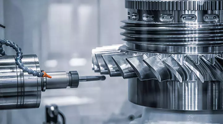
2.3. Designing Blades and Rotors
The design of the blades is critical to the efficiency of the turbine. Engineers use computational fluid dynamics (CFD) software to model how steam will flow over the blades and determine the optimal shape and arrangement of the blades to maximize power output. Rotors, which house the blades, are typically forged from high-strength steel and require precise machining to maintain balance and structural integrity.
2.4. CAD Modeling
Once the general design of the turbine is complete, it is translated into detailed blueprints using computer-aided design (CAD) software. CAD models allow engineers to visualize the entire assembly of the turbine, ensuring that all components fit together correctly and operate without interference. These models also help identify potential points of failure and allow for further refinement of the design.
3. Material Sourcing and Preparation
Once the design phase is completed, the next step in manufacturing is sourcing the materials and preparing them for the assembly process.
3.1. Sourcing High-Quality Metals
The materials used in steam turbines must meet stringent quality standards. Metals for turbine blades, rotors, and casings must be sourced from reliable suppliers, as any imperfections in the material can lead to catastrophic failures during operation. Steel, nickel alloys, and titanium alloys are commonly used in turbine construction due to their high strength and resistance to heat and corrosion.
3.2. Casting and Forging
The turbine blades and rotors are typically manufactured through either casting or forging processes:
- Casting: In casting, molten metal is poured into molds to create the desired shapes. This process is often used for large, complex parts like the turbine casing or nozzle rings.
- Forging: Forging involves shaping metal by heating it to high temperatures and applying pressure. This process is used for parts that require exceptional strength and durability, such as the rotor and main shaft.
Both processes must be carefully controlled to ensure that the materials maintain their structural integrity. Once the casting or forging is complete, the components are heat-treated to improve their strength and resistance to wear.
3.3. Machining
After casting or forging, the components undergo precision machining to achieve the exact dimensions required for the turbine’s assembly. Machining processes such as milling, drilling, and grinding are used to ensure that the parts fit together with minimal tolerances. Turbine blades, in particular, must be machined to extremely tight specifications, as even small deviations in blade geometry can significantly impact the turbine’s performance.
4. Assembly Process
The assembly of a steam turbine is a meticulous process that involves fitting all the individual components together to create a functioning machine. This phase requires a high degree of precision to ensure that the turbine operates safely and efficiently.
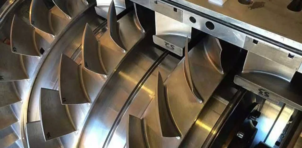
4.1. Blade Assembly
The turbine blades are carefully mounted onto the rotor in a specific arrangement that maximizes the efficiency of steam flow. In impulse turbines, the blades are mounted at an angle to direct the steam onto the next stage of blades. In reaction turbines, the blades are mounted in a way that allows steam to expand as it passes through the stages.
Each blade must be individually inspected and balanced before it is installed, as any imbalance can lead to vibrations that could damage the turbine during operation.
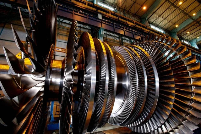
4.2. Rotor and Shaft Installation
The rotor, which houses the blades, is installed onto the main shaft. The shaft is a critical component that transfers the rotational energy from the turbine to the generator or other machinery. The rotor and shaft must be perfectly aligned to ensure smooth rotation and minimize wear on the bearings.
4.3. Casing Assembly
The turbine casing, which contains the steam and directs it onto the blades, is installed around the rotor and blades. The casing must be precisely manufactured to withstand the high pressures and temperatures of the steam. It is typically made from cast steel or cast iron and is bolted together in sections.
4.4. Bearings and Seals
Bearings are installed to support the rotor and shaft, allowing them to spin freely with minimal friction. Steam turbines often use hydrodynamic or ball bearings to handle the high rotational speeds. Seals are also installed to prevent steam leakage and ensure that the steam is directed through the blades rather than escaping into the casing.
5. Testing and Quality Control
Before a steam turbine is ready for operation, it must undergo rigorous testing to ensure that it meets performance standards and operates safely.
5.1. Pressure Testing
The turbine casing is subjected to pressure testing to ensure that it can withstand the steam pressure during operation. Any leaks or weaknesses in the casing are identified and repaired before the turbine is assembled.
5.2. Dynamic Balancing
The rotor and blades are dynamically balanced to ensure smooth operation. Even slight imbalances in the rotor can cause vibrations that lead to wear and tear on the turbine, reducing its lifespan. Balancing is typically done using high-precision equipment that measures the rotor’s rotational stability and adjusts the weight distribution accordingly.
5.3. Performance Testing
The fully assembled turbine is tested under simulated operating conditions to measure its efficiency, power output, and other performance characteristics. Engineers use these tests to verify that the turbine meets its design specifications and performs as expected. If any issues are identified, adjustments are made to improve the turbine’s performance.
5.4. Nondestructive Testing
To ensure the integrity of the turbine components, manufacturers often use nondestructive testing (NDT) methods such as X-rays, ultrasonic testing, and magnetic particle inspection. These techniques allow engineers to detect any internal flaws or cracks in the components without damaging them.
6. Challenges in Steam Turbine Manufacturing
Steam turbine manufacturing is a complex and demanding process that involves several challenges. Overcoming these challenges requires advanced engineering, precision manufacturing, and continuous innovation.
6.1. Material Fatigue and Stress
Steam turbines operate under high-stress conditions, with components subjected to extreme temperatures, pressures, and rotational forces. Over time, these stresses can lead to material fatigue and failure. Manufacturers must carefully select materials and design components to minimize the risk of fatigue and ensure long-term reliability.
6.2. Thermal Expansion
As steam turbines heat up during operation, the metal components expand. This thermal expansion can lead to misalignment of the rotor and blades, reducing the turbine’s efficiency and increasing wear. Engineers must design the turbine with allowances for thermal expansion, ensuring that the components maintain proper alignment even at high temperatures.
6.3. Efficiency Optimization
Improving the efficiency of steam turbines is a constant challenge for manufacturers. Even small increases in efficiency can lead to significant energy savings in large-scale power generation. Engineers use advanced computational models and materials science to optimize blade design, steam flow, and heat transfer within the turbine.
6.4. Environmental Regulations
The manufacturing and operation of steam turbines are subject to strict environmental regulations, particularly concerning emissions and waste. Manufacturers must comply with these regulations by using environmentally friendly materials, reducing emissions during the production process, and designing turbines that operate efficiently with minimal environmental impact.
7. Advancements in Steam Turbine Technology
Steam turbine technology has evolved significantly over the years, with advances in materials science, manufacturing techniques, and design principles driving improvements in performance and efficiency.
7.1. Advanced Materials
New materials, such as high-temperature alloys and ceramics, are being developed to improve the performance of steam turbines. These materials can withstand higher temperatures and pressures, allowing turbines to operate more efficiently and last longer.
7.2. Additive Manufacturing
Additive manufacturing, or 3D printing, is increasingly being used to produce complex turbine components with high precision. This technology allows manufacturers to create intricate blade geometries and optimize material usage, reducing waste and production costs.
7.3. Digital Twins
The use of digital twins—virtual models of physical turbines—allows manufacturers to simulate the performance of a turbine before it is built. Engineers can use digital twins to test different designs, predict maintenance needs, and optimize the turbine’s performance in real time.
7.4. Integration with Renewable Energy
As the world shifts towards renewable energy sources, steam turbines are being integrated into systems that use biomass, geothermal energy, and concentrated solar power. These turbines are designed to operate efficiently with lower-temperature steam, making them suitable for renewable energy applications.
8. Conclusion
Steam turbine manufacturing is a highly specialized field that combines advanced engineering, precision manufacturing, and stringent quality control. From the initial design phase to the final testing of the turbine, every step of the process is crucial to ensuring that the turbine operates safely, efficiently, and reliably.
Despite the challenges involved, steam turbines remain a vital component of modern power generation and industrial processes. As technology continues to evolve, steam turbine manufacturers are finding new ways to improve performance, reduce environmental impact, and meet the growing demand for energy. Through innovations in materials, manufacturing techniques, and digital technologies, the future of steam turbine manufacturing looks brighter than ever.
Steam Turbine Stages
Steam turbines are critical in modern power generation, industrial processes, and other applications requiring the conversion of thermal energy into mechanical work. The operation of a steam turbine involves directing high-pressure, high-temperature steam over a series of blades mounted on a rotor, creating rotational energy. One of the most essential concepts in steam turbine design and operation is the division of the turbine into stages. Each stage of a steam turbine is a step in the process of extracting energy from the steam, and the number and type of stages significantly affect the turbine’s overall efficiency and performance.
In this section, we will explore the concept of steam turbine stages, including the different types of stages, how they function, and their importance in optimizing turbine performance. We will also delve into the challenges associated with designing and managing steam turbine stages and discuss how advancements in technology continue to improve turbine efficiency.
1. The Role of Stages in a Steam Turbine
Steam turbines are designed to convert as much energy from steam as possible into mechanical work. The steam that enters a turbine is typically at very high pressure and temperature, and as it moves through the turbine, it expands and cools. To optimize the energy extraction process, turbines are divided into stages, with each stage extracting a portion of the steam’s energy.
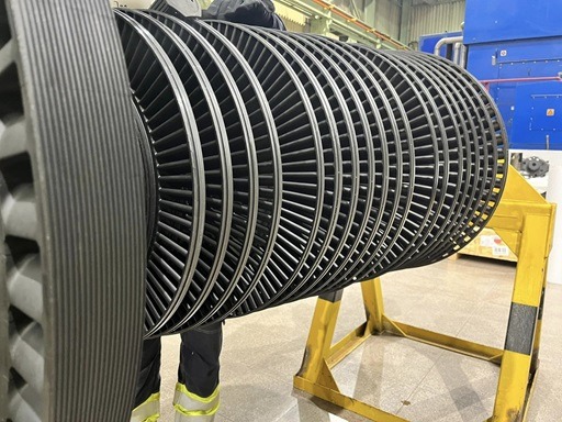
1.1. Definition of a Stage
A single stage in a steam turbine consists of a row of stationary nozzles, called stator blades, and a row of rotating blades, called rotor blades. The stator blades direct the steam onto the rotor blades, causing the rotor to spin. The steam then passes to the next stage, where the process is repeated. As the steam moves through multiple stages, its energy is progressively converted into mechanical energy.
1.2. Types of Energy Transfer
In steam turbines, energy transfer occurs through two mechanisms: impulse and reaction. Depending on the type of turbine, the stages may be based on either impulse, reaction, or a combination of both.
- Impulse stages: In impulse turbines, the steam is directed at high speed through a set of nozzles, where it imparts a direct “push” to the rotor blades, causing them to rotate.
- Reaction stages: In reaction turbines, steam expands both as it moves through the stationary stator blades and as it passes through the rotor blades. The shape of the rotor blades allows the steam to both lift and push them, creating a reaction force that causes rotation.
Most modern turbines use a combination of impulse and reaction stages to optimize efficiency.
2. Types of Steam Turbine Stages
There are several types of steam turbine stages, each designed for different operating conditions and specific performance requirements. Understanding the distinctions between these stages helps in designing turbines for various applications, from power generation to industrial processing.
2.1. Impulse Stages
An impulse stage involves a sharp drop in steam pressure in the nozzles, where the steam is accelerated and directed at high velocity onto the rotor blades. The steam’s kinetic energy is then transferred to the blades, causing the rotor to spin. The key feature of an impulse stage is that most of the energy transfer occurs through changes in steam velocity, rather than changes in pressure within the rotor blades.
2.1.1. Advantages of Impulse Stages
- High efficiency in high-pressure zones: Impulse stages are particularly effective at converting energy from high-pressure steam, making them ideal for the first stages of a turbine where steam pressure is highest.
- Simplicity of blade design: The rotor blades in an impulse stage are relatively simple in shape, which makes them easier to manufacture and maintain.
2.1.2. Challenges with Impulse Stages
- Pressure drop limitations: While impulse stages are efficient in high-pressure environments, they become less efficient as steam pressure drops. As a result, they are usually limited to the early stages of a turbine.
- Mechanical stress: The high-speed impact of steam on the rotor blades in an impulse stage can cause significant mechanical stress, requiring durable materials and careful design.
2.2. Reaction Stages
In a reaction stage, the steam experiences a pressure drop as it passes through both the stator and rotor blades. The rotor blades are designed to create lift as the steam expands and accelerates through them, producing a reaction force that causes the rotor to spin. Unlike impulse stages, reaction stages extract energy through both velocity and pressure changes.
2.2.1. Advantages of Reaction Stages
- Better efficiency at lower pressures: Reaction stages are more efficient in the lower-pressure sections of a turbine, making them ideal for the later stages where the steam has lost much of its pressure.
- Smoother operation: Because the pressure drop is distributed more evenly across the stages, reaction turbines tend to operate more smoothly and with less mechanical stress on individual components.
2.2.2. Challenges with Reaction Stages
- Complex blade design: The rotor blades in a reaction stage are more complex to design and manufacture compared to those in an impulse stage, due to the need to optimize both pressure drop and velocity changes.
- Higher leakage losses: The pressure differences between the stator and rotor blades can lead to steam leakage, which reduces the overall efficiency of the turbine.
2.3. Compounding of Stages
Most steam turbines use multiple stages to optimize energy extraction. The two primary methods of compounding stages are pressure compounding and velocity compounding.
2.3.1. Pressure Compounding
In pressure-compounded turbines, steam expands progressively through a series of impulse stages. Each stage involves a significant drop in pressure, with the steam passing through multiple sets of nozzles and blades. This design allows for efficient energy extraction at high pressures and helps manage the mechanical stresses on the turbine.
2.3.2. Velocity Compounding
In velocity-compounded turbines, the steam’s velocity is reduced across multiple sets of blades without a significant drop in pressure. This method is often used in the first stages of a turbine to reduce the steam’s velocity before it enters the main stages, preventing excessive wear on the blades and improving overall efficiency.
2.4. Mixed-Flow Stages
Some turbines use a combination of impulse and reaction stages, known as mixed-flow stages. This approach allows engineers to optimize the turbine’s performance by using impulse stages in high-pressure zones and reaction stages in lower-pressure zones. Mixed-flow designs are common in large power-generating turbines, where efficiency and durability are paramount.
Importance of Staging in Turbine Efficiency
The number and arrangement of stages in a steam turbine play a crucial role in determining the turbine’s overall efficiency. Each stage extracts a portion of the steam’s energy, and the goal is to maximize this extraction while minimizing losses. Key factors that influence the efficiency of a turbine’s stages include the following:
3.1. Energy Distribution
The amount of energy extracted from the steam in each stage depends on the pressure and temperature of the steam, the design of the blades, and the arrangement of the stages. Engineers must carefully balance the distribution of energy extraction across the stages to ensure that the turbine operates efficiently.
3.2. Minimizing Steam Losses
Steam leakage between stages and around the blades can significantly reduce turbine efficiency. Proper design of the sealing systems and careful alignment of the blades are essential to minimizing these losses.
3.3. Thermodynamic Efficiency
Each stage of the turbine must be designed to operate as close to its theoretical thermodynamic efficiency as possible. This involves optimizing the shape and arrangement of the blades to ensure that the maximum amount of energy is transferred from the steam to the rotor in each stage.
4. Challenges in Stage Design
Designing the stages of a steam turbine involves numerous challenges, particularly in balancing the need for high efficiency with the practical limitations of manufacturing, material strength, and operating conditions.
4.1. Material Constraints
The materials used in turbine blades must withstand extreme temperatures and pressures, as well as the mechanical stresses caused by high rotational speeds. Engineers must select materials that can resist corrosion, erosion, and fatigue, while also maintaining the strength needed to handle the steam’s energy. Modern turbines often use high-strength alloys or composite materials to achieve these goals.
4.2. Blade Erosion
Steam turbines are susceptible to blade erosion, particularly in later stages where the steam may contain moisture. Water droplets in the steam can strike the blades at high speeds, causing them to wear down over time. Blade erosion can reduce the efficiency of the turbine and lead to costly repairs or replacements.
To mitigate erosion, manufacturers use erosion-resistant coatings on the blades and design them to minimize the accumulation of water droplets. Additionally, ensuring that the steam remains as dry as possible throughout the turbine can help reduce erosion.
4.3. Vibration and Mechanical Stress
The high rotational speeds of steam turbines can cause vibrations and mechanical stress on the rotor and blades. Engineers must carefully balance the rotor to prevent vibrations from damaging the turbine and ensure that the blades are designed to handle the forces generated during operation. Fatigue and creep (the slow deformation of materials under stress) are major concerns in turbine stage design.
4.4. Heat Management
The stages of a steam turbine must operate at very high temperatures, particularly in the early stages where steam enters at its highest pressure and temperature. This creates a significant heat management challenge, as the turbine components must be able to withstand thermal expansion without becoming misaligned or damaged.
5. Technological Advances in Steam Turbine Stages
Advances in technology have enabled engineers to improve the efficiency, durability, and performance of steam turbine stages. These innovations are helping to extend the lifespan of turbines, reduce maintenance costs, and improve energy efficiency.
5.1. Computational Fluid Dynamics (CFD)
Computational fluid dynamics (CFD) is a powerful tool used to simulate the behavior of steam as it flows through the turbine stages. CFD allows engineers to analyze the effects of different blade designs, steam velocities, and pressure drops, optimizing the turbine’s performance without the need for costly physical testing.
5.2. Additive Manufacturing
Additive manufacturing (3D printing) has made it possible to create complex turbine blade designs with high precision. This technology allows for the production of intricate blade geometries that optimize steam flow and improve energy extraction. Additionally, additive manufacturing reduces the time and cost associated with producing turbine components.
5.3. Advanced Coatings
New coating technologies are being developed to protect turbine blades from erosion, corrosion, and high-temperature degradation. These coatings can extend the lifespan of the blades, reducing the need for frequent maintenance and improving the overall reliability of the turbine.
6. Conclusion
Steam turbine stages are the foundation of efficient energy extraction in turbines. By dividing the turbine into multiple stages, engineers can maximize the amount of energy converted from steam into mechanical work. The design of each stage, whether impulse, reaction, or mixed-flow, plays a critical role in determining the turbine’s overall performance.
Despite the challenges associated with stage design, including material limitations, blade erosion, and mechanical stress, technological advancements continue to improve turbine efficiency and reliability. As new materials, manufacturing techniques, and simulation tools become available, the future of steam turbine stages looks promising, with continued improvements in energy efficiency, durability, and performance.
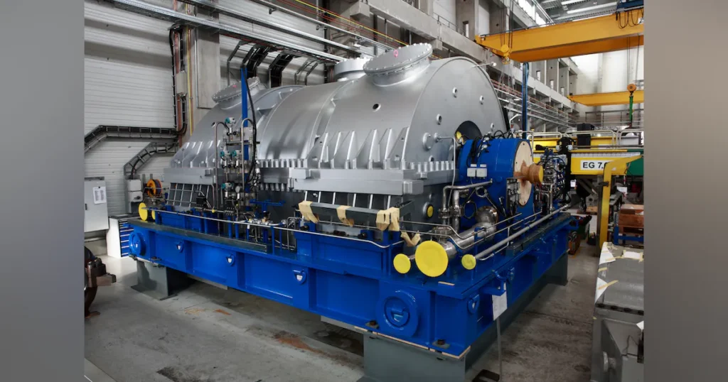
Industrial steam turbines are integral to modern energy systems, converting heat energy into mechanical work to generate electricity or drive machinery. These turbines have evolved over a century of development, from early designs that powered factories and ships to highly advanced systems that drive today’s power plants and industrial processes.
Early steam turbines laid the groundwork for the rapid industrialization of the 20th century. Today, steam turbines are widely used in power generation, petrochemicals, pulp and paper, and even food processing industries. This document explores their operation, types, applications, and future developments, reflecting their continuing role in global industrial energy systems.
Basic Principles of Steam Turbines
At their core, steam turbines operate by harnessing the thermal energy in steam to perform mechanical work. The process begins by superheating water in a boiler, which transforms into steam. This high-pressure steam is directed through a series of turbine blades, causing the rotor to spin, converting thermal energy into mechanical energy.
Key topics:
- Thermodynamics: Discuss the Rankine cycle, which is the basic thermodynamic cycle governing steam turbine operations.
- Mechanical to Electrical Energy: How generators convert mechanical rotation into electricity.
- Saturated vs. Superheated Steam: How different steam states affect efficiency and output.
Types of Industrial Steam Turbines
Industrial steam turbines come in various types based on application and design. This section will outline the main categories:
- Condensing Turbines: Commonly used in power generation, these turbines release exhaust steam at low pressures to maximize energy extraction.
- Back-pressure (Non-condensing) Turbines: Typically used in cogeneration applications, these turbines exhaust steam at higher pressures for additional industrial processes like heating.
- Impulse vs. Reaction Turbines: Impulse turbines use high-pressure steam jets to impact blades, while reaction turbines work by steam expansion along the blade surface.
Design and Construction of Steam Turbines
Steam turbines consist of several critical components designed for efficiency and durability:
- Rotor and Blades: Discuss the importance of blade design in maximizing energy transfer, the use of high-strength materials, and anti-corrosion coatings.
- Casing and Nozzles: The role of high-pressure steam in efficient turbine operation.
- Blade Materials: High-temperature alloys and innovations in metallurgy.
This section will also touch on challenges like managing vibration, noise, and blade fatigue, as well as technological advances in blade cooling techniques and aerodynamic designs.
Operation and Performance
Operating steam turbines efficiently requires careful monitoring and control of various parameters, including steam pressure, temperature, and flow rate. This section will describe typical start-up and shutdown procedures, as well as strategies for performance optimization through steam quality management and operational adjustments.
Key topics:
- Operational Efficiency: Analyzing key metrics like thermal efficiency, mechanical losses, and parasitic losses.
- Common Operational Issues: Addressing corrosion, erosion, and steam quality.
- Maintenance Best Practices: Routine inspections, preventive maintenance schedules, and component replacement strategies.
Applications in Power Generation
Steam turbines are the backbone of thermal power plants, whether fossil fuel-based, nuclear, or renewable. This section will cover the various types of power plants where steam turbines are used, focusing on their role in:
- Coal, Gas, and Oil-fired Power Plants: Discuss the Rankine cycle’s role in fossil-fuel power generation.
- Nuclear Power: How steam turbines function in nuclear plants, particularly in pressurized and boiling water reactors.
- Renewable Energy Integration: The role of steam turbines in biomass and geothermal power generation.
- Combined-cycle Power Plants: A comparison with gas turbines in modern power systems.
Industrial Applications Beyond Power Generation
While power generation is the most common application, steam turbines are also widely used in various industrial processes:
- Cogeneration and District Heating: How industrial plants use steam turbines to produce both power and heat.
- Petrochemical Industry: The role of turbines in refining processes.
- Pulp and Paper Manufacturing: Steam turbines for combined heat and power in paper mills.
- Desalination: The integration of steam turbines in large-scale desalination plants.
Efficiency and Performance Improvements
Advances in steam turbine design are continuously pushing the boundaries of efficiency. Some areas of improvement include:
- Blade Design and Aerodynamics: How modern blade profiles maximize efficiency.
- Digitalization: The role of sensors and AI in monitoring performance and predicting maintenance needs.
- Retrofitting Older Systems: Updating older turbines with modern technology for better performance.
Challenges and Limitations
Industrial steam turbines face challenges related to:
- Material Limitations: Corrosion, erosion, and fouling are major concerns.
- Regulatory Pressures: Compliance with emissions standards and efficiency benchmarks.
- Competitors: How steam turbines compare with other technologies like gas and wind turbines.
Future Trends and Innovations
The future of industrial steam turbines will be shaped by technological advancements and global energy trends:
- Hybrid Systems: Combining steam and gas turbines for enhanced efficiency.
- Hydrogen Integration: The potential of hydrogen-powered steam systems.
- AI and IoT: Predictive maintenance and real-time performance monitoring for better operational efficiency.
Conclusion
The conclusion will summarize the key points covered in the document, highlighting the continuing relevance of industrial steam turbines in both traditional and modern energy landscapes. It will also touch on the potential future developments and innovations that could reshape the role of steam turbines in global energy systems.
Industrial Steam Turbines
Industrial steam turbines are fundamental components of power generation and industrial processes worldwide, playing a critical role in converting heat energy into mechanical work and electricity. From small-scale applications in manufacturing plants to massive power generation facilities, steam turbines remain one of the most efficient and reliable technologies for energy conversion. These turbines function by utilizing high-pressure steam produced by heating water in boilers. The steam passes through a series of blades, causing the turbine to rotate and generate mechanical work. This process, dating back more than a century, remains crucial in the modern industrial landscape.
Historically, steam turbines were developed in the late 19th century as an evolution of earlier steam engines, which were significantly less efficient and more cumbersome. The invention of the steam turbine is often credited to Sir Charles Parsons, who introduced the first practical design in 1884. His design revolutionized marine propulsion, power generation, and many industrial processes, ushering in an era of rapid industrialization. As the industrial revolution progressed, steam turbines became more advanced and widely adopted in power plants, oil refineries, chemical processing plants, and other sectors.
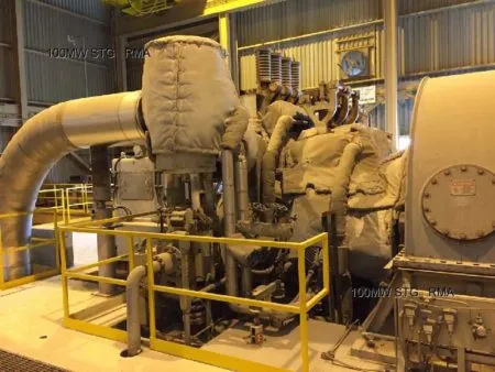
Today, steam turbines are key components in a broad range of energy systems, from fossil fuel-based power plants to renewable energy setups. In power generation, they are primarily used in thermal plants, where coal, gas, or nuclear reactions heat water to create steam. In industrial applications, steam turbines drive machinery, compress gases, or generate electricity as part of cogeneration systems. These turbines can range in size from small units producing a few megawatts to giant turbines capable of generating several hundred megawatts, depending on the application.
Modern steam turbine technology has advanced to achieve high efficiencies through innovative materials, precision engineering, and digital monitoring systems. The versatility of steam turbines allows them to be integrated into diverse energy systems, including combined-cycle power plants, where they work in tandem with gas turbines, and geothermal or biomass plants, where they harness renewable steam sources.
With increasing global energy demands and the transition toward cleaner and more efficient energy sources, steam turbines continue to evolve. Efficiency improvements, integration with renewable energy technologies, and advancements in digitalization, such as predictive maintenance and AI-driven monitoring systems, are shaping the future of steam turbines. They also play a vital role in decarbonization efforts, particularly when coupled with carbon capture technologies or integrated into hybrid energy systems.
In conclusion, industrial steam turbines are integral to the global energy infrastructure, providing reliable, efficient, and scalable power generation solutions. From their historical origins to modern-day innovations, they remain a cornerstone of both traditional and emerging energy systems, ensuring their relevance well into the future.
Basic Principles of Steam Turbines
Industrial steam turbines operate based on well-established thermodynamic principles, converting thermal energy from steam into mechanical work. This section will discuss the key principles, energy conversion process, steam properties, and the basic components that make up a steam turbine.
Thermodynamics of Steam Power
Steam turbines rely on the Rankine cycle, a thermodynamic process that describes how heat energy is converted into mechanical work in a closed-loop system. The cycle consists of four main stages:
- Heat Addition (Boiler): Water is heated in a boiler until it becomes steam, either saturated or superheated, depending on the application. This phase is crucial for generating the high-pressure steam needed to drive the turbine.
- Expansion (Turbine): The high-pressure steam is directed onto turbine blades, causing them to rotate. As the steam expands through the turbine stages, it loses pressure and temperature, transferring its energy to the rotor. This expansion is the core process where thermal energy is converted into mechanical energy.
- Condensation (Condenser): After passing through the turbine, the low-pressure steam enters a condenser, where it is cooled and returned to liquid form. This process helps maintain efficiency by creating a pressure difference that drives steam flow through the turbine.
- Pressurization (Pump): The condensed water is pumped back to the boiler under high pressure, completing the cycle.
The Rankine cycle is the most commonly used thermodynamic process in industrial steam turbines, particularly in power generation. Its efficiency depends on factors such as the temperature and pressure of the steam entering the turbine, the effectiveness of the condenser, and the efficiency of the turbine blades.
Conversion of Thermal Energy to Mechanical Energy
The primary purpose of a steam turbine is to convert thermal energy from steam into mechanical work. This energy conversion occurs when high-pressure steam enters the turbine and interacts with the blades. Steam turbines use either impulse or reaction principles to achieve this conversion, depending on their design.
- Impulse Principle: In impulse turbines, high-pressure steam is directed through nozzles, which convert the steam’s thermal energy into kinetic energy. The resulting high-speed steam jets strike the turbine blades, causing them to rotate. The pressure remains constant as the steam flows through the turbine stages, while its velocity decreases. Impulse turbines are commonly used in applications where high-pressure steam is available, such as in power plants.
- Reaction Principle: In reaction turbines, steam expands continuously as it passes over the turbine blades, which are designed to act as nozzles. The pressure drop occurs directly within the blade passages, and both the velocity and pressure of the steam decrease as it progresses through the turbine. Reaction turbines are typically used in applications with lower pressure or when maximizing efficiency at lower steam velocities is essential.
Both impulse and reaction turbines are often combined in multi-stage configurations to optimize energy conversion across different steam pressure and velocity ranges.
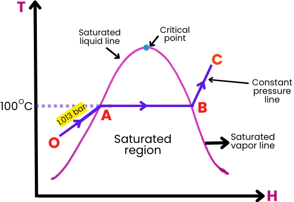
Types of Steam: Saturated vs. Superheated
The properties of the steam used in a turbine significantly impact its performance and efficiency. Two key types of steam are commonly used in industrial steam turbines:
- Saturated Steam: Saturated steam exists at a temperature corresponding to the boiling point of water at a given pressure. It contains a mixture of water vapor and liquid, making it ideal for applications where heat recovery is required, such as in cogeneration systems. However, because saturated steam contains water droplets, it can cause erosion and reduce the efficiency of turbine blades over time.
- Superheated Steam: Superheated steam is produced by heating saturated steam beyond its boiling point, at which point it becomes completely dry and free of water droplets. Superheated steam is preferred for most power generation applications because it allows for greater efficiency. The absence of moisture reduces the risk of blade erosion, and its higher temperature provides more energy for conversion into mechanical work.
The choice between saturated and superheated steam depends on the specific application, with superheated steam offering advantages in high-efficiency power generation systems.
Basic Components of a Steam Turbine
Steam turbines consist of several key components, each of which plays a crucial role in the energy conversion process:
- Rotor: The rotor is the central rotating part of the turbine, onto which the blades are mounted. As the steam flows through the turbine, it causes the rotor to spin, converting thermal energy into mechanical work. The rotor is typically supported by bearings and connected to a generator or mechanical system to perform useful work.
- Blades: Turbine blades are the primary components that interact with the steam. They are precisely engineered to extract maximum energy from the high-pressure steam. Blades in impulse turbines are shaped to change the direction of the steam jets, while reaction turbine blades are designed to create pressure drops as the steam passes over them. Blade materials must withstand high temperatures and stresses, and they are often made of heat-resistant alloys or coated with protective materials to prevent erosion.
- Casing: The casing encloses the turbine and contains the steam as it flows through the turbine stages. It is designed to withstand high pressures and temperatures. Casings are typically made from materials that can tolerate the thermal expansion and mechanical stresses caused by the steam.
- Nozzles: In impulse turbines, nozzles play a critical role in converting the thermal energy of the steam into kinetic energy. These nozzles direct high-speed steam jets onto the blades, ensuring efficient energy transfer.
- Bearings: Bearings support the rotor and allow it to spin smoothly. They must be capable of handling the high-speed rotation and the weight of the turbine assembly while minimizing friction and wear.
- Condenser: In condensing turbines, the condenser is responsible for cooling and condensing the exhaust steam back into water. This process reduces the steam’s pressure, enhancing the efficiency of the turbine by maintaining a large pressure differential across the turbine stages.
Together, these components form a highly efficient machine capable of converting the thermal energy in steam into mechanical work, which can then be used for power generation or other industrial processes.
Types of Industrial Steam Turbines
Industrial steam turbines are designed to meet various energy conversion needs across different sectors. Depending on the application, steam conditions, and desired output, steam turbines can be classified into several types. The most common types include condensing turbines, non-condensing (back-pressure) turbines, and extraction turbines. Additionally, turbines can be categorized based on their working principles into impulse turbines and reaction turbines. Understanding these types and their functions is key to selecting the appropriate turbine for a given application.
Condensing Turbines
Condensing steam turbines are one of the most widely used types in industrial power generation, particularly in large-scale power plants. These turbines operate by condensing the exhaust steam after it passes through the turbine, allowing for maximum energy extraction. The condensing process significantly lowers the pressure of the exhaust steam, thereby increasing the pressure differential between the steam entering and leaving the turbine. This increased pressure difference allows the turbine to extract as much energy as possible from the steam.
- Mechanism: In a condensing turbine, steam is introduced at a high pressure and temperature into the turbine. As the steam passes through multiple stages of the turbine, it expands and loses pressure and temperature, causing the rotor to spin. After completing the energy conversion process, the low-pressure exhaust steam is directed into a condenser, where it is cooled and converted back into liquid water. The condensed water is then pumped back into the boiler to repeat the cycle.
- Applications: Condensing turbines are primarily used in large-scale thermal power plants, including coal, natural gas, and nuclear power stations. They are designed to generate electricity efficiently by maximizing energy extraction from the steam. In these plants, the condenser is often connected to a cooling tower or a body of water to remove the heat generated during the condensation process.
- Advantages:
- High efficiency due to the large pressure drop across the turbine.
- Ideal for applications focused solely on power generation.
- Disadvantages:
- Condensers require significant amounts of cooling water, which may not be available in all locations.
- The overall system is more complex, requiring additional equipment such as condensers and cooling towers.
Non-condensing (Back-pressure) Turbines
Non-condensing, or back-pressure turbines, are used in applications where the steam is needed for industrial processes after passing through the turbine. Unlike condensing turbines, these turbines do not exhaust steam at low pressures. Instead, the exhaust steam is used at a higher pressure for additional purposes, such as heating or driving industrial processes.
- Mechanism: In a back-pressure turbine, high-pressure steam enters the turbine and expands, causing the rotor to rotate and perform mechanical work. However, instead of being condensed, the exhaust steam exits the turbine at a relatively high pressure. This steam can then be used for other processes, such as heating buildings, drying products, or running auxiliary equipment in industrial plants.
- Applications: Back-pressure turbines are commonly used in cogeneration systems, where both electricity and heat are produced simultaneously. Industrial plants, such as chemical factories, pulp and paper mills, and refineries, often use back-pressure turbines to generate electricity while using the exhaust steam for heating or other processes. This makes them highly efficient for applications that require both power and steam.
- Advantages:
- Highly efficient in cogeneration applications since both the electricity and steam are utilized.
- Lower capital costs compared to condensing turbines, as condensers and cooling systems are not needed.
- Ideal for applications where steam is required for processes beyond power generation.
- Disadvantages:
- Less efficient for purely power generation purposes, as not all energy is extracted from the steam.
- Limited to locations or industries where the exhaust steam can be effectively utilized.
Extraction and Regenerative Turbines
Extraction turbines are a hybrid design that allows steam to be extracted at one or more intermediate points during its expansion process within the turbine. This design enables the turbine to supply steam at different pressures for industrial processes, while still generating electricity. The remaining steam continues to expand and is either exhausted as in a back-pressure turbine or condensed as in a condensing turbine.
- Mechanism: In extraction turbines, steam is partially expanded in the turbine to generate power. At one or more stages of the turbine, a portion of the steam is “extracted” and redirected for use in other processes. The remaining steam continues through the turbine for further energy extraction. By controlling the amount and pressure of the extracted steam, the turbine can meet varying steam demands while continuing to generate electricity.
- Applications: Extraction turbines are frequently used in cogeneration and combined heat and power (CHP) plants, where steam is needed for both electricity generation and industrial applications. Industries such as chemical processing, refineries, and paper mills benefit from this type of turbine, as they can use the extracted steam for heating or other processes while producing electricity.
- Advantages:
- Flexible operation: Steam can be extracted at different pressures to meet various process requirements.
- Efficient use of steam for both power generation and industrial processes.
- Disadvantages:
- More complex control systems are needed to manage steam extraction and maintain turbine efficiency.
- The design is more complicated compared to non-extraction turbines, leading to higher initial costs.
Impulse vs. Reaction Turbines
Steam turbines are also categorized based on the mechanism they use to convert the steam’s energy into mechanical work. The two main types are impulse turbines and reaction turbines.
- Impulse Turbines: In an impulse turbine, steam is directed through nozzles that convert the steam’s pressure energy into high-velocity jets. These jets then strike the blades of the turbine, causing the rotor to spin. The pressure of the steam remains constant as it passes through the blades, while its velocity decreases. Impulse turbines are often used in applications with high-pressure steam and are known for their simplicity and durability.
- Applications: Impulse turbines are used in high-pressure stages of steam power plants and in marine propulsion systems.
- Advantages:
- Simple design with fewer stages, which reduces mechanical complexity.
- High durability and resistance to damage from steam impurities.
- Disadvantages:
- Less efficient in converting energy at low pressures, leading to a need for multi-stage setups in many applications.
- Reaction Turbines: In a reaction turbine, the steam expands as it passes over the blades, causing a continuous pressure drop. Both the moving and stationary blades act as nozzles, with the pressure energy being converted into both velocity and mechanical work. Reaction turbines are commonly used in lower-pressure applications and provide higher efficiency in these conditions.
- Applications: Reaction turbines are often used in lower-pressure stages of power plants, as well as in applications where steam pressure is lower to begin with.
- Advantages:
- Higher efficiency at lower steam pressures and velocities.
- Smoother operation due to gradual energy transfer.
- Disadvantages:
- More complex design with more stages, leading to higher manufacturing and maintenance costs.
- Increased susceptibility to damage from steam impurities, requiring better steam quality.
Combination of Impulse and Reaction Turbines
In practice, many industrial steam turbines use a combination of both impulse and reaction designs to optimize efficiency across different pressure and temperature stages. For example, the high-pressure stages may use impulse turbines, while the lower-pressure stages use reaction turbines, creating a highly efficient energy conversion system.
Design and Construction of Steam Turbines
Steam turbine design is a complex engineering discipline aimed at maximizing the efficiency and reliability of the machine. A typical industrial steam turbine consists of several critical components, each designed to withstand high temperatures, pressures, and mechanical stresses. This section will focus on the design of major components such as the rotor, blades, casing, and nozzles, as well as the materials used and recent technological advancements.
Major Components of a Steam Turbine
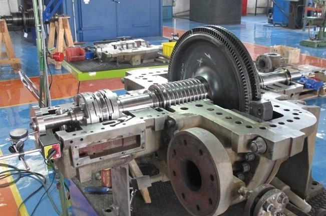
- Rotor
- The rotor is the heart of the steam turbine. It is a long shaft onto which turbine blades are mounted and is responsible for transmitting the mechanical energy generated by the rotating blades. The rotor is directly connected to the generator or mechanical system that the turbine drives.
- Rotors are usually made from high-strength steel alloys that can withstand the centrifugal forces created by high-speed rotation. They must also be resistant to thermal expansion and contraction as temperatures fluctuate during operation.
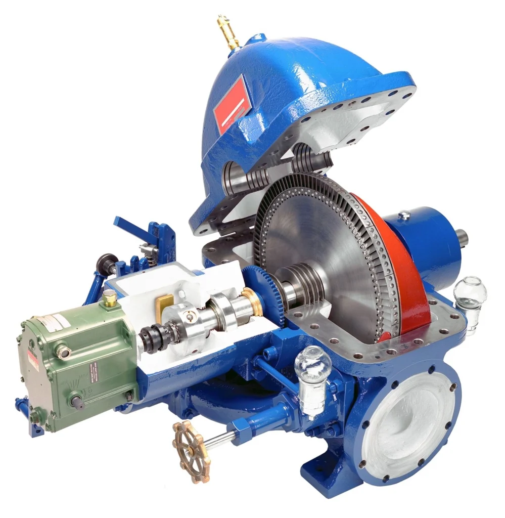
- Blades
- The blades are arguably the most critical components of a steam turbine, as they are responsible for converting the energy from the steam into mechanical rotation. Turbine blades must be carefully designed to handle the high-pressure and high-temperature steam that passes over them.
- Blade Profile and Shape: Blade shape and aerodynamic profile play a significant role in the turbine’s efficiency. Engineers use computational fluid dynamics (CFD) to model steam flow over the blades and optimize their design for maximum energy extraction.
- Materials: Steam turbine blades are typically made from specialized alloys, often based on nickel or chromium, that can endure high temperatures (up to 600°C) and pressures. In some advanced designs, blades are coated with ceramic or thermal barrier coatings to enhance their durability and resistance to corrosion and erosion.
- Fixed and Moving Blades: Turbines typically consist of alternating rows of fixed and moving blades. The fixed blades (stators) redirect the steam flow, while the moving blades (rotors) extract energy from the steam. This alternating arrangement ensures efficient energy transfer from the steam to the turbine rotor.
- Casing
- The casing encloses the turbine and directs steam through the different stages of the turbine. It must withstand both the internal pressure of the steam and the mechanical stresses generated by the rotating rotor and blades.
- Casing materials are usually high-strength steels or cast iron, designed to handle the thermal expansion caused by high operating temperatures. The casing is often lined with insulation to minimize heat loss and maintain operational efficiency.
- Nozzles
- In impulse turbines, nozzles play a crucial role by converting the steam’s thermal energy into kinetic energy. These nozzles are positioned to direct high-velocity steam jets onto the turbine blades. In reaction turbines, nozzles are incorporated into the blade design itself, allowing the steam to expand continuously as it passes through the turbine.
- The design of nozzles involves precision engineering to ensure that steam flow is directed efficiently at the blades, minimizing energy losses.
- Bearings
- Bearings support the rotor and ensure smooth rotation with minimal friction. Since the rotor operates at high speeds, bearings must be carefully designed to handle both radial and axial forces while minimizing vibration. Bearings are typically made from wear-resistant materials such as specialized steel or ceramic composites.
- Turbines may use oil-lubricated bearings or more advanced magnetic bearings, which reduce friction and wear, leading to improved longevity and performance.
- Seals
- Seals are used to prevent steam from escaping at the points where the rotor passes through the casing. This is critical for maintaining efficiency and minimizing energy losses. Seals are designed to withstand high temperatures and pressures, ensuring that steam remains within the turbine’s operating system.
- Common seal designs include labyrinth seals, which consist of a series of ridges and grooves that reduce steam leakage by creating multiple points of resistance to steam flow.
Materials Used in Turbine Construction
The choice of materials is essential in turbine construction, as the components must endure extreme temperatures, high pressures, and corrosive environments. Engineers typically use materials that have a high strength-to-weight ratio, can withstand thermal stress, and resist corrosion and erosion from the steam. Some common materials include:
- Steel Alloys: High-strength steel alloys are commonly used for components such as the rotor and casing. These alloys are designed to handle high pressures and resist fatigue caused by the continuous rotational forces during operation.
- Nickel-based Alloys: Turbine blades and other critical components exposed to high temperatures are often made from nickel-based superalloys. These materials are ideal for maintaining their strength at elevated temperatures, offering excellent resistance to oxidation and creep (the slow deformation of materials under stress).
- Chromium-based Alloys: Chromium-based alloys are also used in turbine blades and other high-temperature areas. These alloys offer excellent corrosion resistance, especially in environments where steam contains impurities or chemicals.
- Ceramic Coatings: Advanced steam turbines may use ceramic coatings on turbine blades to provide additional thermal protection and reduce wear. These coatings help extend the lifespan of the blades, particularly in environments where erosion and corrosion are significant concerns.
Design Considerations for Efficiency and Durability
Steam turbine design focuses on maximizing efficiency while ensuring durability and reliability. Key design considerations include:
- Aerodynamics of Blades
- The aerodynamic profile of turbine blades is critical for efficiency. Engineers optimize blade shapes to minimize energy losses due to friction and turbulence as steam flows over them. Modern turbines use highly specialized blade profiles that ensure smooth, laminar flow to maximize energy transfer from the steam to the rotor.
- Multistage Turbines
- Most industrial steam turbines are multistage systems, where steam passes through several stages of blades before exiting the turbine. In each stage, the steam expands, losing pressure and temperature, and transferring energy to the blades. Multistage designs allow for more efficient energy extraction, particularly when dealing with high-pressure steam.
- Cooling Systems
- In high-temperature applications, blade cooling is essential to maintain efficiency and prevent damage. Some turbines use internal cooling systems that circulate air or coolant through the blades, reducing the temperature and extending their operational life. Blade cooling is particularly important in turbines using superheated steam.
- Vibration and Noise Management
- High-speed turbines are prone to vibration, which can lead to mechanical wear and damage over time. Modern turbine designs incorporate advanced bearing systems and vibration-damping technologies to minimize these effects. Noise reduction is also an important design consideration, especially for turbines operating in urban areas or near sensitive environments.
Advances in Turbine Blade Technology
In recent years, significant advancements in turbine blade technology have led to improvements in both efficiency and durability:
- 3D Printed Blades: Additive manufacturing (3D printing) has enabled the production of more complex and precise blade designs, improving aerodynamic performance and reducing manufacturing costs. 3D-printed blades can be optimized for specific flow patterns, leading to higher efficiency and reduced material waste.
- Advanced Blade Coatings: New thermal barrier coatings and erosion-resistant materials are being developed to protect turbine blades from high temperatures and harsh environments. These coatings reduce wear and corrosion, extending the operational life of the turbine.
- Smart Blades: Some modern turbines incorporate sensors within the blades to monitor temperature, pressure, and vibration in real-time. These “smart blades” provide valuable data that can be used to optimize turbine performance and predict maintenance needs before issues arise.
Operation and Performance of Steam Turbines
The efficient operation of a steam turbine requires careful management of steam conditions, performance monitoring, and proper maintenance. Steam turbines are designed to operate reliably for extended periods under varying loads and conditions. This section will explore the procedures for starting and stopping turbines, operational efficiency metrics, common issues encountered during operation, and strategies to optimize performance and minimize downtime.
Start-up and Shutdown Procedures
Operating a steam turbine involves specific start-up and shutdown procedures to ensure the turbine functions safely and efficiently. These procedures are designed to manage thermal stress on the turbine’s components, particularly the rotor and blades, which can experience significant temperature changes during these phases.
- Start-up Procedure:
- Pre-Checks: Before starting the turbine, a series of checks are performed to ensure that all systems are operational. This includes checking the lubrication system, ensuring the steam supply is at the correct pressure and temperature, and verifying that all safety interlocks are in place.
- Warming Up: The turbine must be gradually warmed up to avoid thermal shock. Steam is slowly introduced at a reduced pressure and temperature to gradually heat the rotor, blades, and casing. This step is crucial to avoid damage due to rapid temperature changes, which can cause thermal expansion and material fatigue.
- Synchronization: Once the turbine reaches operating speed, it must be synchronized with the electrical grid (in the case of power generation) or the mechanical system it is driving. Synchronization ensures that the turbine’s output matches the grid’s frequency or the system’s load requirements.
- Shutdown Procedure:
- Load Reduction: Before shutting down the turbine, its load is gradually reduced. This allows the system to cool down and prevents excessive mechanical stress on the components.
- Steam Shut-off: After the load is reduced, the steam supply is shut off, and the turbine is allowed to coast down to a stop. The rotor continues to spin for some time after the steam is cut off, so the lubrication system must remain active until the turbine comes to a complete stop.
- Cooling Down: The turbine must be allowed to cool down gradually to avoid thermal stress. This cooling period helps prevent damage to the rotor and blades, which could occur if the turbine is exposed to rapid temperature changes.
Operational Efficiency Metrics
Several key metrics are used to assess the operational efficiency of a steam turbine. These metrics help operators monitor performance and make adjustments to optimize energy conversion and reduce losses.
- Thermal Efficiency:
- Thermal efficiency refers to how effectively a turbine converts the thermal energy of steam into mechanical energy. It is calculated as the ratio of the useful mechanical energy output to the total thermal energy input from the steam. High thermal efficiency is critical in minimizing fuel consumption and reducing operating costs, particularly in power generation applications.
- Factors that affect thermal efficiency include steam pressure, temperature, and quality (i.e., whether the steam is saturated or superheated).
- Heat Rate:
- The heat rate is another key metric used in power generation. It is defined as the amount of energy (typically in British Thermal Units, or BTUs) required to produce one kilowatt-hour (kWh) of electricity. A lower heat rate indicates better turbine performance, as less energy is needed to generate the same amount of electricity.
- Heat rate can be influenced by the turbine’s design, operating conditions, and the quality of the steam. Operators continually monitor heat rate to ensure that the turbine is running efficiently.
- Mechanical Losses:
- Mechanical losses occur due to friction in the bearings, seals, and other moving parts of the turbine. These losses reduce the amount of mechanical energy available for electricity generation or driving industrial equipment. High-quality lubrication systems and well-maintained bearings help minimize these losses.
- Parasitic Losses:
- Parasitic losses are the energy consumed by auxiliary systems that are necessary for the turbine’s operation, such as the lubrication system, pumps, and cooling systems. These losses reduce the overall efficiency of the power plant or industrial process, so minimizing parasitic losses is an important aspect of turbine operation.
Common Issues During Operation
Steam turbines are generally reliable machines, but they can experience operational issues that impact performance and longevity. Some of the most common issues include:
- Corrosion:
- Corrosion can occur when steam contains impurities such as oxygen or other chemicals. Over time, corrosion can weaken turbine components, particularly the blades and casing, leading to reduced efficiency and potential failure.
- To mitigate corrosion, steam is typically treated to remove impurities before it enters the turbine. Additionally, anti-corrosion coatings can be applied to turbine blades and other vulnerable parts.
- Erosion:
- Erosion is caused by solid particles or water droplets in the steam impinging on the turbine blades at high velocity. This can lead to the gradual wearing away of the blades, reducing their aerodynamic efficiency and increasing the risk of failure.
- Erosion is especially common in turbines using saturated steam, which may contain water droplets. Using superheated steam or installing erosion-resistant coatings on the blades can reduce the impact of erosion.
- Steam Quality:
- The quality of steam has a significant impact on turbine performance. Poor-quality steam, which contains water droplets or solid particles, can cause both erosion and corrosion, reducing the turbine’s efficiency and lifespan.
- Maintaining high-quality steam through proper boiler operation, water treatment, and steam conditioning systems is critical to minimizing these risks.
- Vibration and Fatigue:
- Vibration is a common issue in high-speed turbines and can lead to mechanical fatigue over time. Vibration can be caused by imbalances in the rotor, misalignment of bearings, or flow disturbances in the steam path.
- Regular monitoring of vibration levels and the use of advanced bearing systems can help prevent excessive wear and avoid mechanical failures.
Performance Monitoring and Optimization Strategies
To ensure optimal performance, modern steam turbines are equipped with sensors and monitoring systems that provide real-time data on key operating parameters. These systems allow operators to make adjustments and prevent potential issues before they lead to costly downtime.
- Real-Time Monitoring:
- Sensors installed throughout the turbine measure parameters such as steam pressure, temperature, rotor speed, and vibration. This data is analyzed by a control system that automatically adjusts operating conditions to maintain optimal performance.
- Operators can use this data to identify trends and predict potential problems, allowing for proactive maintenance and reducing the risk of unplanned outages.
- Digitalization and Predictive Maintenance:
- Digitalization is playing an increasingly important role in turbine operation and maintenance. Predictive maintenance systems use data from sensors and advanced analytics, including artificial intelligence (AI), to predict when a component is likely to fail. This allows operators to schedule maintenance during planned downtime, reducing the likelihood of unexpected failures.
- AI-driven systems can also help optimize performance by analyzing data trends and recommending adjustments to steam conditions, load distribution, or operating speeds.
- Regular Maintenance:
- Routine maintenance is essential for keeping steam turbines operating efficiently. Regular inspections of the rotor, blades, bearings, and seals can help identify wear and tear before it leads to significant performance issues.
- Typical maintenance activities include lubricating bearings, inspecting seals for leaks, checking steam quality, and monitoring vibration levels.
Applications in Power Generation
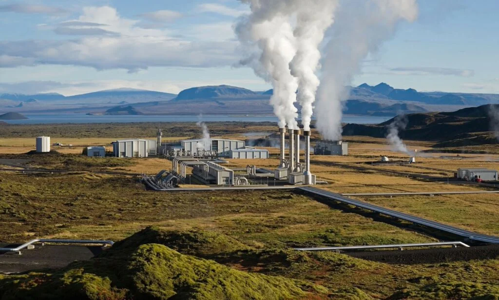
Steam turbines are an essential component of the global power generation industry. Their ability to efficiently convert thermal energy into mechanical and electrical energy makes them a cornerstone of energy production in various types of power plants, from fossil-fuel-based systems to nuclear and renewable energy facilities. This section explores the role of steam turbines in power generation across different fuel sources and technologies, emphasizing their importance in both traditional and modern energy systems.
Steam Turbines in Fossil-Fuel Power Plants
Fossil-fuel power plants—such as those that use coal, natural gas, and oil—are among the most common applications of steam turbines. In these plants, steam turbines are employed to convert the thermal energy generated by burning fossil fuels into electrical energy. Despite the global shift toward cleaner energy sources, fossil-fuel power plants continue to generate a significant portion of the world’s electricity, particularly in regions where access to renewable energy is limited.
- Coal-fired Power Plants:
- In a traditional coal-fired power plant, coal is burned in a boiler to generate heat. This heat is used to convert water into high-pressure steam, which is then directed into the steam turbine. As the steam expands through the turbine, it causes the rotor to spin, generating mechanical energy that is then converted into electricity by a generator.
- Role of Steam Turbines: Steam turbines in coal-fired plants are typically large, multi-stage machines designed to handle high-pressure, superheated steam. Their efficiency is critical to the plant’s overall performance, as coal combustion produces large amounts of thermal energy that must be efficiently converted into electricity.
- Environmental Concerns: Coal-fired power plants are associated with significant environmental issues, including greenhouse gas emissions and air pollution. While steam turbines themselves do not produce emissions, they are integral to the process of converting the energy produced by coal combustion into electricity. Many modern coal plants incorporate pollution control technologies, such as carbon capture and storage (CCS), to mitigate their environmental impact.
- Natural Gas-fired Power Plants:
- Natural gas is used in two main types of power plants: simple-cycle gas plants and combined-cycle gas plants. In a simple-cycle plant, natural gas is burned in a combustion chamber, and the high-temperature exhaust gases are used to spin a gas turbine. In a combined-cycle plant, the exhaust heat from the gas turbine is used to generate steam, which is then directed into a steam turbine to produce additional electricity. This combination increases the overall efficiency of the power plant.
- Role of Steam Turbines in Combined-Cycle Plants: In combined-cycle gas plants, steam turbines play a crucial role in utilizing the waste heat from the gas turbine, making the overall system more efficient. This process can increase the plant’s efficiency from around 30-40% (in simple-cycle operation) to more than 60% in combined-cycle mode.
- Environmental Benefits: Compared to coal, natural gas produces fewer emissions of carbon dioxide (CO₂), sulfur dioxide (SO₂), and particulate matter. Combined-cycle plants, in particular, are considered one of the most efficient and environmentally friendly fossil-fuel-based power generation technologies.
- Oil-fired Power Plants:
- Oil-fired power plants operate similarly to coal-fired plants, with oil being burned in a boiler to produce steam, which drives the steam turbine. These plants are less common today due to the higher cost of oil compared to coal and natural gas, as well as environmental concerns.
- Applications: Oil-fired plants are often used in regions where natural gas and coal are less accessible, or as backup power sources in places like remote islands or industrial facilities.
Role of Steam Turbines in Nuclear Power Plants
Nuclear power plants rely on steam turbines to convert the thermal energy produced by nuclear fission into electricity. These plants are designed to operate continuously at high output levels, making steam turbines an essential component of their overall efficiency and reliability.
- Pressurized Water Reactors (PWRs):
- In pressurized water reactors (PWRs), nuclear fission takes place in the reactor core, generating heat that is used to produce high-pressure steam. The steam is then routed to the steam turbine, where it expands and spins the turbine rotor, generating mechanical energy that is converted into electricity.
- Steam Turbines in PWRs: In PWR systems, the steam that drives the turbine is typically superheated, allowing for greater efficiency in energy conversion. The steam turbine is designed to handle the specific conditions of nuclear power plants, including high reliability and resistance to radiation.
- Boiling Water Reactors (BWRs):
- In a boiling water reactor (BWR), water is heated directly by the nuclear reactor to produce steam, which is sent directly to the steam turbine. BWRs use the steam generated within the reactor itself, eliminating the need for a separate steam generator.
- Challenges in BWRs: Since the steam that drives the turbine comes directly from the reactor, the turbine must be designed to handle potential contamination from radioactive materials. Special materials and design considerations are required to ensure safe and reliable operation.
- Advantages of Nuclear Steam Turbines:
- High Capacity: Steam turbines used in nuclear power plants are often among the largest in the world, with the ability to generate several hundred megawatts of electricity. Their size and capacity are crucial for meeting the base-load power requirements of many countries.
- Environmental Benefits: Nuclear power is a low-carbon energy source, making it an attractive option for reducing greenhouse gas emissions. Steam turbines play a vital role in the efficiency of nuclear plants, ensuring that the thermal energy produced by nuclear reactions is effectively converted into electricity.
Steam Turbines in Renewable Energy: Biomass and Geothermal Plants
In addition to fossil fuels and nuclear power, steam turbines are also used in renewable energy applications, particularly in biomass and geothermal power plants. These renewable energy sources offer a cleaner alternative to traditional power generation, and steam turbines help maximize their efficiency.
- Biomass Power Plants:
- Biomass power plants use organic materials such as wood, agricultural waste, or dedicated energy crops to generate heat. The combustion of biomass produces steam, which is then directed into a steam turbine to generate electricity.
- Advantages of Steam Turbines in Biomass Plants:
- Biomass is considered carbon-neutral, as the CO₂ released during combustion is offset by the CO₂ absorbed during the growth of the biomass. This makes biomass plants an environmentally friendly alternative to fossil-fuel plants.
- Steam turbines in biomass plants are similar to those used in fossil-fuel plants, with modifications to accommodate the lower energy content of biomass fuel compared to coal or gas.
- Geothermal Power Plants:
- Geothermal power plants harness the heat stored beneath the Earth’s surface to generate steam, which drives steam turbines to produce electricity. In these plants, geothermal reservoirs provide naturally occurring steam or hot water, which is converted into mechanical energy by the turbine.
- Types of Geothermal Plants:
- Dry Steam Plants: These plants use steam directly from geothermal wells to drive the turbine.
- Flash Steam Plants: In flash steam plants, hot water from geothermal reservoirs is depressurized to produce steam, which is then used in the turbine.
- Binary Cycle Plants: In binary cycle plants, geothermal water heats a secondary fluid with a lower boiling point, which vaporizes and drives the turbine.
- Advantages of Geothermal Steam Turbines:
- Geothermal power is a highly reliable and continuous energy source, as geothermal heat is available 24/7. Steam turbines in geothermal plants operate with high reliability and can be integrated with binary systems for greater efficiency.
Combined-Cycle Power Plants: Integration of Steam and Gas Turbines
Combined-cycle power plants are one of the most efficient forms of power generation, utilizing both gas turbines and steam turbines to maximize energy output. In these plants, the exhaust heat from a gas turbine is used to generate steam, which is then directed into a steam turbine to produce additional electricity. This dual-turbine approach significantly increases the plant’s overall efficiency, often exceeding 60%.
- Operation: In a combined-cycle plant, natural gas is burned in a combustion chamber, driving a gas turbine. The high-temperature exhaust gases are used to heat water in a heat recovery steam generator (HRSG), producing steam. The steam is then sent to a steam turbine, where it generates additional electricity.
- Advantages of Combined-Cycle Plants:
- Higher Efficiency: By utilizing both gas and steam turbines, combined-cycle plants achieve much higher efficiency than traditional single-cycle power plants.
- Lower Emissions: Combined-cycle plants produce fewer emissions compared to coal or oil plants due to their higher efficiency and the cleaner nature of natural gas as a fuel.
- Flexibility: These plants can respond quickly to changes in electricity demand, making them ideal for balancing grid load, especially in regions with a high share of intermittent renewable energy sources like wind or solar.
Economic and Environmental Considerations
Steam turbines are central to the economic and environmental performance of power plants. Their efficiency directly influences the cost of electricity generation and the plant’s environmental footprint.
- Efficiency and Cost:
- Higher efficiency turbines reduce fuel consumption, which lowers operating costs and reduces the plant’s overall environmental impact. For example, improving the thermal efficiency of a coal-fired power plant by just a few percentage points can lead to significant reductions in fuel use and greenhouse gas emissions.
- Environmental Impact:
- The environmental impact of steam turbines depends largely on the energy source they are paired with. In fossil-fuel plants, steam turbines play a role in emissions management through the efficient conversion of thermal energy into electricity. In nuclear and renewable plants, they help reduce greenhouse gas emissions by providing a reliable, low-carbon energy source.
Industrial Applications Beyond Power Generation
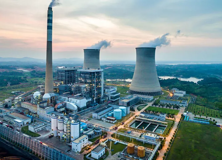
While steam turbines are commonly associated with power generation, their use extends far beyond electricity production. Steam turbines play a vital role in various industrial applications, where they provide both mechanical power and heat for industrial processes. In many industries, steam turbines are integrated into systems that produce both electricity and useful thermal energy in what is known as cogeneration or combined heat and power (CHP) systems. This section explores the critical role of steam turbines in industrial sectors such as petrochemical refining, pulp and paper manufacturing, food processing, and desalination.
Cogeneration and District Heating
Cogeneration, also known as combined heat and power (CHP), is a highly efficient system that generates both electricity and useful heat from the same energy source. Steam turbines are often at the heart of cogeneration systems, where they not only produce electricity but also provide thermal energy for industrial processes or heating applications. This dual-purpose use of energy improves overall efficiency and reduces waste.
- Cogeneration Systems:
- In a typical cogeneration system, steam is generated in a boiler, and a portion of the steam is used to drive a steam turbine and generate electricity. The remaining steam, instead of being condensed and wasted, is extracted at an intermediate pressure and used for industrial processes, heating, or cooling.
- Advantages:
- Higher Efficiency: By utilizing the waste heat from electricity generation, cogeneration systems can achieve efficiencies of 70-90%, compared to the 30-40% efficiency of conventional power plants.
- Cost Savings: Cogeneration reduces fuel costs by producing both electricity and heat from a single energy source.
- Environmental Benefits: Since cogeneration uses less fuel to produce the same amount of energy, it results in lower emissions of carbon dioxide (CO₂) and other pollutants.
- District Heating:
- Steam turbines are also used in district heating systems, where the heat produced during electricity generation is used to supply hot water or steam for heating buildings in urban areas. This is particularly common in cold climates, where district heating systems provide an efficient way to heat homes, offices, and industrial facilities.
- Applications: District heating systems are widespread in countries like Denmark, Sweden, and Russia, where they contribute to significant energy savings and reduce the need for individual heating systems in each building.
Steam Turbines in the Petrochemical and Refining Industries
The petrochemical and refining industries are major users of steam turbines, where they are employed to drive mechanical equipment, such as compressors, pumps, and fans, as well as to generate electricity as part of cogeneration systems.
- Mechanical Drive Applications:
- In many petrochemical plants and refineries, steam turbines are used to provide mechanical power for large compressors and pumps. These machines are essential for processes such as refining crude oil, compressing natural gas, and producing chemicals.
- Advantages:
- Reliability: Steam turbines provide continuous, reliable mechanical power, making them ideal for processes that must operate 24/7 without interruption.
- Fuel Flexibility: Steam turbines in these industries can use the heat generated from waste products or by-products, such as process gas, to produce steam, enhancing overall efficiency.
- Cogeneration in Refineries:
- Refineries often use cogeneration systems to produce both electricity and steam for their internal processes. For example, steam is used for distillation processes, cracking, and other heat-intensive operations, while electricity generated by the turbines powers the plant’s equipment.
- Example: In a typical refinery, steam turbines may drive large compressors that help separate and refine different hydrocarbon fractions from crude oil.
Pulp and Paper Manufacturing
The pulp and paper industry is another major user of steam turbines, where they are integrated into combined heat and power systems to provide the electricity and steam required for paper production. This industry relies heavily on steam for drying paper products and for mechanical processes such as pulping.
- Cogeneration in Pulp and Paper Mills:
- Pulp and paper mills use cogeneration to generate electricity and heat from the same steam. The steam is used to drive turbines for power generation, while the remaining steam is directed into industrial processes such as drying, cooking, and heating.
- Process: Biomass or waste wood from the paper production process is often used as fuel to generate steam, making this a highly sustainable approach. The steam drives a turbine to generate electricity, and the residual steam is used for drying paper and other manufacturing steps.
- Efficiency: Steam turbines help paper mills achieve high energy efficiency by making use of both electricity and heat. This reduces the need for external energy sources, lowering costs and minimizing the mill’s carbon footprint.
- Mechanical Drive:
- Steam turbines in pulp and paper plants are also used to drive mechanical equipment such as pumps, fans, and compressors, which are essential for the production process.
Steam Turbines in the Food Processing Industry
The food processing industry uses steam turbines in various ways, primarily to drive mechanical equipment and provide heat for cooking, sterilization, and drying processes. The ability to generate both electricity and steam from a single energy source makes steam turbines ideal for food processing plants.
- Sterilization and Cooking:
- Steam is used extensively in food processing for sterilizing equipment, pasteurizing products, and cooking food items in industrial-scale operations. The steam needed for these processes can be produced as a by-product of electricity generation in a cogeneration system.
- Example: A food processing plant may use a steam turbine to generate electricity while utilizing the waste steam for cooking and sterilization processes, optimizing fuel usage.
- Energy Efficiency:
- Similar to other industries, the food processing industry benefits from the high energy efficiency of cogeneration systems. By capturing the heat produced during electricity generation, food processors can significantly reduce their energy costs and lower their environmental impact.
Desalination Plants
Steam turbines are also used in desalination plants, which convert seawater into fresh water. Desalination is an energy-intensive process, and steam turbines provide an efficient solution for both electricity generation and mechanical drive applications within these plants.
- Thermal Desalination Processes:
- Thermal desalination plants, such as multi-stage flash (MSF) desalination, rely on steam to heat seawater and evaporate it. The steam is produced by a boiler or recovered from a cogeneration system, and the heat is used to evaporate seawater, leaving behind salt and other impurities.
- Role of Steam Turbines: Steam turbines in desalination plants are used to generate electricity and drive the pumps and compressors that are essential for the desalination process. By integrating steam turbines into the plant’s energy system, desalination facilities can achieve higher efficiencies and reduce operating costs.
- Cogeneration and Desalination:
- Many desalination plants use cogeneration systems, where the steam turbine generates both electricity and the heat needed for the desalination process. This reduces the overall energy consumption of the plant and makes desalination more economically viable, especially in regions with limited freshwater resources.
Other Industrial Applications
Steam turbines are also used in various other industries, including:
- Chemical Manufacturing:
- In chemical manufacturing plants, steam turbines provide mechanical power and process heat for chemical reactions, distillation, and other heat-intensive processes. Cogeneration is often used to improve energy efficiency in chemical plants.
- Steel and Cement Production:
- Steel and cement plants use steam turbines to generate electricity and drive mechanical equipment. Waste heat from the production process is often recovered to generate steam, making these plants more energy-efficient.
Efficiency and Performance Improvements
Improving the efficiency and performance of steam turbines has been a focal point of research and development in the energy and industrial sectors. Increased efficiency means extracting more useful energy from the same amount of fuel, reducing operating costs, and minimizing environmental impact. Technological advancements, materials innovation, and better operational practices have all contributed to significant improvements in the performance of steam turbines. This section explores the various methods and technologies that have enhanced turbine efficiency, including advanced blade design, digitalization, turbine cooling, steam quality optimization, and retrofitting older turbines.
Advanced Blade and Turbine Design
The design of turbine blades is critical to the overall efficiency of a steam turbine. Blades are responsible for converting steam energy into mechanical work, and their shape, material, and aerodynamic properties significantly influence turbine performance. Recent advances in blade design and materials science have led to more efficient turbines that can operate at higher temperatures and pressures.
- Aerodynamic Blade Profiles:
- Modern steam turbines use advanced blade profiles that are optimized for the smooth, laminar flow of steam. Engineers use computational fluid dynamics (CFD) simulations to design blade shapes that minimize turbulence and energy loss as steam passes through the turbine stages.
- Three-dimensional (3D) Blades: In traditional turbine designs, blades were mostly two-dimensional. However, modern turbines employ 3D blades that have complex curvature and variable angles of attack. These 3D blades improve steam flow control, reducing secondary losses (caused by steam spilling over the edges of blades) and improving the efficiency of energy transfer.
- Longer and More Efficient Blades:
- Advances in materials and manufacturing technologies have allowed for the creation of longer turbine blades that can operate at higher temperatures and rotational speeds. Longer blades increase the surface area for steam interaction, allowing for greater energy extraction per stage.
- Last-stage Blades: In low-pressure turbine sections, the last-stage blades are particularly important for maximizing efficiency. Longer, highly efficient last-stage blades help capture more energy from the exhaust steam, reducing energy losses and improving overall turbine performance.
- Advanced Materials:
- The development of high-temperature, corrosion-resistant materials has also contributed to improvements in turbine efficiency. Steam turbine blades are now commonly made from nickel-based superalloys or titanium alloys, which can withstand extreme temperatures and high levels of stress without degrading.
- Protective Coatings: Blade coatings, such as ceramic thermal barrier coatings (TBCs) and erosion-resistant coatings, provide additional protection against the harsh environment inside the turbine. These coatings reduce wear and extend the operational life of the blades, maintaining high performance over longer periods.
Turbine Cooling and Steam Quality Optimization
High temperatures improve the efficiency of steam turbines, as higher thermal energy in the steam allows for more effective energy conversion. However, these temperatures can also place enormous stress on turbine components. Cooling technologies and steam quality management play an essential role in maintaining efficiency while preventing damage to the turbine.
- Internal Blade Cooling:
- In high-efficiency turbines, especially those using superheated steam, blade cooling systems are essential for preventing thermal damage. Internal cooling systems circulate coolant (often air or steam) through channels within the turbine blades, reducing the temperature of the blade surfaces while allowing the turbine to operate at higher steam temperatures.
- Innovations in Cooling Technology: Advances in cooling technology, including the use of more efficient cooling channels and coatings, have enabled steam turbines to handle increasingly higher inlet steam temperatures. This helps improve the thermal efficiency of the turbine while ensuring long-term reliability.
- Optimizing Steam Quality:
- The quality of the steam used in a turbine significantly impacts its efficiency and longevity. Superheated steam is preferred in power generation applications due to its higher energy content and the absence of moisture, which can cause blade erosion.
- Moisture Control: Moisture in the steam can reduce efficiency by increasing energy losses through condensation and causing damage to the turbine blades. Advanced steam separators and reheaters are used in modern turbines to ensure that only dry, high-quality steam enters the turbine stages.
- Reheat Cycles: Some turbines employ a reheat cycle, where steam is partially expanded in the turbine, then sent back to the boiler to be reheated before continuing through the turbine. Reheating increases the steam’s temperature and energy content, leading to greater efficiency.
Role of Digitalization and AI in Performance Monitoring
The digitalization of steam turbine systems has enabled operators to continuously monitor turbine performance, optimize operations in real-time, and predict maintenance needs. Digital tools, sensors, and advanced analytics are revolutionizing the way turbines are managed, leading to significant improvements in both efficiency and reliability.
- Real-Time Monitoring and Data Analytics:
- Modern steam turbines are equipped with a range of sensors that measure key parameters such as temperature, pressure, rotor speed, vibration, and steam flow. These sensors feed data into advanced analytics systems, which provide operators with real-time insights into turbine performance.
- Predictive Analytics: By analyzing historical data and trends, predictive analytics systems can identify potential performance issues before they lead to failures. This allows operators to schedule maintenance during planned downtime, reducing the risk of unplanned outages and optimizing turbine efficiency.
- AI-driven Performance Optimization:
- Artificial intelligence (AI) systems are increasingly being used to optimize turbine operations. AI algorithms can analyze large amounts of performance data, identify inefficiencies, and recommend adjustments to operating conditions, such as steam pressure, load distribution, or turbine speed.
- Digital Twins: One emerging technology is the use of digital twins—virtual models of steam turbines that simulate real-world operating conditions. Digital twins allow engineers to test different scenarios, optimize turbine designs, and predict how the turbine will respond to varying operating conditions, all without disrupting the actual system.
- Maintenance and Condition Monitoring:
- Predictive maintenance systems use digital tools and AI to monitor the condition of critical turbine components, such as blades, bearings, and seals. These systems can detect signs of wear, corrosion, or misalignment, enabling timely maintenance and preventing efficiency losses due to degraded components.
- Vibration Monitoring: Vibration is a common issue in high-speed turbines, and excessive vibration can lead to mechanical fatigue and failure. Digital monitoring systems continuously track vibration levels, allowing operators to take corrective actions before serious damage occurs.
Efficiency vs. Cost: Economic Trade-offs
While increasing efficiency is a major goal for turbine operators, there are often economic trade-offs between achieving maximum efficiency and managing costs. Turbine upgrades, retrofits, and advanced materials can significantly improve performance, but they also come with associated costs. Operators must balance the investment in new technologies with the long-term savings in fuel costs and maintenance.
- Upgrading to Higher-efficiency Designs:
- Upgrading older turbines with more efficient blades, advanced materials, and digital monitoring systems can yield substantial efficiency gains. However, these upgrades require significant capital investment, and operators must carefully evaluate the return on investment (ROI) before proceeding.
- Cost-benefit Analysis: A thorough cost-benefit analysis is essential when considering upgrades or retrofits. The long-term benefits of improved efficiency, reduced fuel consumption, and extended equipment life must be weighed against the upfront costs of new components and installation.
- Balancing Efficiency and Reliability:
- In some cases, maximizing efficiency may not be the best approach if it compromises reliability or increases the risk of component failure. For example, pushing turbines to operate at their maximum thermal limits may result in higher efficiency, but it could also reduce the lifespan of critical components such as blades and seals.
- Optimized Operating Points: Many turbine operators use digital tools to find the optimal operating point, where the turbine achieves the best balance between efficiency, reliability, and operational costs.
Retrofitting and Upgrading Older Turbines
As the global energy industry evolves, many operators are retrofitting older steam turbines with modern technology to improve performance and extend their operational life. Retrofitting is a cost-effective way to enhance turbine efficiency without completely replacing existing systems.
- Retrofitting for Efficiency Gains:
- Common retrofit solutions include upgrading blades to more aerodynamic designs, installing more efficient bearings, and integrating modern control systems. These upgrades can improve the turbine’s heat rate, reduce parasitic losses, and increase overall energy output.
- Steam Path Upgrades: Retrofitting the steam path, which includes the nozzles, blades, and seals, can significantly reduce energy losses and improve the turbine’s capacity to handle higher pressures and temperatures.
- Integration with Digital Monitoring Systems:
- Older turbines can also be retrofitted with digital monitoring and control systems, enabling real-time performance tracking and predictive maintenance capabilities. These systems improve operational efficiency by identifying inefficiencies and preventing costly downtime.
Basic Principles of Industrial Steam Turbines
Steam turbines are mechanical devices that convert the thermal energy of steam into mechanical work, which can then be used to generate electricity or power industrial equipment. Since their invention in the late 19th century, steam turbines have become essential components of modern energy infrastructure, playing a vital role in power generation, petrochemical refining, and other industries.
The development of the steam turbine marked a significant leap forward from early steam engines, which were inefficient and bulky. Sir Charles Parsons and Gustaf de Laval were pioneers in developing the first practical steam turbines, which revolutionized industries by providing more efficient energy conversion mechanisms.
Steam turbines are commonly found in power plants—both fossil-fuel and nuclear—and in various industrial applications such as district heating, cogeneration, and mechanical drive systems for compressors and pumps. Their ability to operate efficiently under high-pressure and high-temperature conditions makes them indispensable for converting heat energy into mechanical power on an industrial scale.
Thermodynamic Principles
At the core of steam turbine operation is thermodynamics, particularly the Rankine cycle. The Rankine cycle is a thermodynamic process that describes how heat is transformed into work in a steam turbine system. This cycle typically includes four stages:
- Heat Addition (Boiler): Water is heated to form steam in a boiler at constant pressure.
- Expansion (Turbine): The high-pressure steam expands through the turbine, converting its thermal energy into mechanical work.
- Condensation (Condenser): The expanded steam is cooled in a condenser, returning to a liquid state.
- Pressurization (Pump): The condensed water is then pumped back to the boiler to begin the cycle again.
In steam turbines, energy conversion is based on the principles of entropy and enthalpy. As steam expands within the turbine, its entropy increases while its enthalpy decreases. This drop in enthalpy is what drives the turbine rotor, producing mechanical energy.
Understanding the thermodynamic principles behind steam turbines is crucial for optimizing their performance. Concepts such as isentropic efficiency, enthalpy drop, and steam enthalpy diagrams (Mollier diagrams) help engineers design turbines that maximize energy conversion while minimizing losses.
Steam Properties and Their Role in Turbine Efficiency
The properties of the steam used in a turbine—such as pressure, temperature, and steam quality—have a direct impact on turbine efficiency. The two main types of steam used in turbines are:
- Saturated Steam: Steam that is at the boiling point for its pressure. It contains both liquid and vapor phases.
- Superheated Steam: Steam heated beyond its boiling point at a given pressure, making it dry and containing no water droplets.
Superheated steam is typically used in industrial steam turbines due to its higher energy content and efficiency. The temperature and pressure of the steam entering the turbine determine the amount of work that can be extracted.
The quality of steam is also important, particularly when considering the presence of moisture in the steam. Wet steam can cause erosion of turbine blades and reduce efficiency. In high-efficiency systems, steam reheat and moisture separators are used to maintain high steam quality and prevent damage to the turbine components.
Types of Industrial Steam Turbines
Steam turbines are classified based on their working principles and applications. The two primary types are:
- Impulse Turbines:
- In impulse turbines, high-pressure steam is directed through nozzles, converting thermal energy into kinetic energy. This high-velocity steam jet impacts the turbine blades, causing the rotor to spin.
- Impulse turbines maintain constant pressure as steam flows through the turbine, while the velocity decreases.
- Reaction Turbines:
- In reaction turbines, the steam expands continuously as it flows over the blades. Both the moving blades and stationary blades serve as nozzles, allowing the steam to drop in pressure as it progresses through the turbine stages.
- Reaction turbines extract energy by utilizing both steam pressure and velocity changes across the blades.
Steam turbines are further classified by their applications, including condensing turbines (which maximize energy extraction by condensing exhaust steam) and non-condensing turbines (used in industrial processes where the steam is needed for heating after expansion). Extraction turbines allow steam to be extracted at various pressure levels for industrial processes, while back-pressure turbines exhaust steam at higher pressures for further use.
Components of a Steam Turbine
Steam turbines consist of several key components, each designed to withstand high pressures, temperatures, and rotational forces:
- Rotor:
- The rotor is a shaft that carries the turbine blades and is the main rotating part of the turbine. It converts the energy from steam into mechanical work. Rotors are usually made from high-strength alloys that can endure high thermal and mechanical stresses.
- Blades:
- Blades are mounted on the rotor and play a key role in converting steam energy into rotational motion. They come in various shapes and sizes, depending on the type of turbine and the stage of energy extraction.
- Blade Materials: Turbine blades are typically made of specialized alloys that can withstand high temperatures and pressures. Materials like nickel-based alloys or titanium are often used, with thermal coatings to prevent corrosion and erosion.
- Casings and Nozzles:
- The casing encloses the turbine, guiding steam flow and providing structural integrity. Nozzles are used to direct steam onto the blades, particularly in impulse turbines, where they convert steam pressure into velocity.
- Seals and Bearings:
- Seals prevent steam leakage, while bearings support the rotor and allow it to spin smoothly. These components are critical for ensuring efficient operation and minimizing energy losses.
- Control Systems:
- Modern steam turbines are equipped with advanced control systems that regulate steam flow, rotor speed, and load distribution. Governors play a key role in maintaining operational stability by adjusting the steam supply based on load demand.
Working Stages of a Steam Turbine
Industrial steam turbines are typically multi-stage machines, where steam passes through multiple sets of blades to extract energy more efficiently. The stages are divided into:
- High-Pressure (HP) Stage: Where steam enters at its highest pressure and temperature, delivering the maximum energy.
- Intermediate-Pressure (IP) Stage: Steam expands further, losing pressure but still containing significant energy for conversion.
- Low-Pressure (LP) Stage: By the time steam reaches this stage, its pressure and temperature are lower, but the remaining energy is extracted to maximize efficiency.
Each stage is designed to handle specific steam conditions, optimizing the energy conversion process. Blade staging ensures that energy is extracted gradually, preventing sudden drops in pressure that could damage the turbine or reduce efficiency.
Energy Conversion Efficiency
The efficiency of a steam turbine is determined by how well it converts the thermal energy in steam into mechanical work. Key factors influencing turbine efficiency include:
- Thermal Efficiency:
- The thermal efficiency of a steam turbine measures how effectively it converts heat into mechanical work. A highly efficient turbine will extract as much energy as possible from the steam before exhausting it.
- Heat Rate:
- Heat rate is a critical metric used to assess a power plant’s efficiency. It refers to the amount of fuel energy required to generate one unit of electricity. Lower heat rates indicate higher efficiency.
- Reheat Cycles:
- In a reheat cycle, steam is partially expanded in the turbine and then returned to the boiler to be reheated. This increases the efficiency of the cycle by allowing the turbine to extract more energy from the steam at a higher temperature.
- Mechanical Losses:
- Losses due to friction in bearings, seals, and other moving parts reduce the overall efficiency of the turbine. Minimizing these mechanical losses is key to maintaining high performance.
Steam Flow Dynamics
The flow of steam through a turbine is governed by complex fluid dynamics. Steam behaves differently depending on its velocity, pressure, and temperature, and the design of the turbine blades and nozzles plays a key role in managing these variables.
- Laminar vs. Turbulent Flow:
- Laminar flow refers to smooth, orderly steam movement, while turbulent flow is chaotic and less efficient. Engineers design turbines to maintain laminar flow as much as possible, reducing energy losses due to turbulence.
- Steam Speed and Pressure Gradients:
- As steam expands in the turbine, its speed increases while its pressure drops. The design of turbine blades ensures that these changes are controlled, allowing the steam to transfer its energy effectively to the rotor.
Operation and Maintenance of Steam Turbines
Efficient operation and proper maintenance are essential for the long-term performance of steam turbines. Key operational practices include:
- Start-up and Shutdown Procedures:
- Steam turbines must be carefully started and shut down to prevent thermal shock and mechanical stress. Gradually introducing steam at controlled temperatures and pressures helps maintain the turbine’s integrity.
- Common Operational Issues:
- Vibration: High-speed rotation can cause vibration, leading to mechanical wear and reduced efficiency. Advanced bearings and vibration monitoring systems are used to mitigate this issue.
- Corrosion and Erosion: Steam impurities can cause corrosion and erosion of turbine blades, reducing their lifespan and performance. Water treatment and anti-corrosion coatings are used to prevent this.
- Predictive Maintenance:
- Modern turbines are equipped with sensors that monitor performance in real-time. Predictive maintenance systems use this data to predict when components are likely to fail, allowing operators to perform maintenance before a breakdown occurs.
Future Trends in Steam Turbine Technology
As the energy industry evolves, so too do steam turbine technologies. Key trends include:
- Advanced Blade Materials:
- The development of new alloys and coatings is enabling turbines to operate at higher temperatures and pressures, improving efficiency.
- Digitalization and AI:
- The integration of digital tools, such as AI-driven performance optimization and digital twins, is enhancing turbine efficiency by allowing operators to monitor and adjust operations in real-time.
- Sustainability:
- Steam turbines are being integrated into renewable energy systems, such as biomass and geothermal plants, and are playing a role in carbon capture and storage (CCS) efforts, making them more relevant in the transition to cleaner energy sources.
Conclusion
Steam turbines have been, and will continue to be, fundamental to industrial energy conversion. Their principles of operation, based on thermodynamics and fluid dynamics, are essential for understanding how heat energy is transformed into mechanical work.
As industries seek to improve energy efficiency and reduce emissions, steam turbines will remain a critical technology, supported by advancements in materials science, digital monitoring, and sustainability initiatives.
Introduction to Industrial Steam Turbines
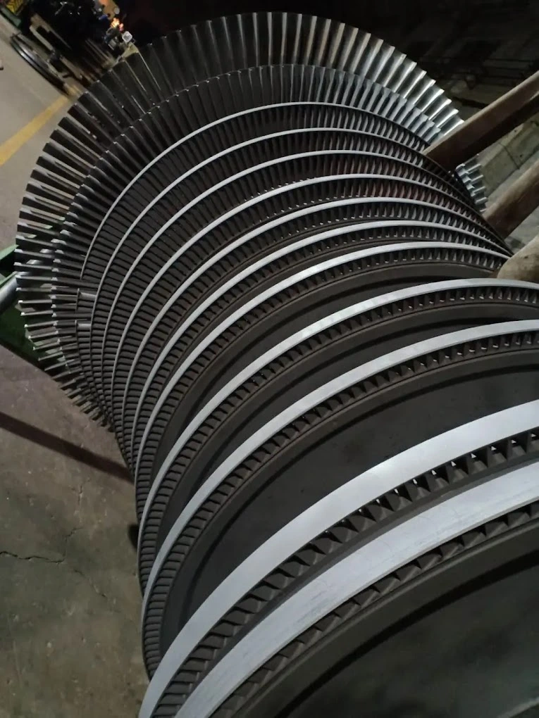
Industrial steam turbines are among the most critical components in energy conversion systems, used primarily for generating electricity and providing mechanical power in various industries. Their ability to efficiently transform thermal energy from steam into mechanical work makes them indispensable in a wide range of industrial applications, from power generation to petrochemical refining and beyond.
A steam turbine works by using high-pressure steam to rotate a series of blades mounted on a shaft (the rotor). As steam passes through the turbine, its energy is transferred to the blades, causing the rotor to spin. This rotational energy can then be used to drive an electrical generator or mechanical equipment. The fundamental principle behind steam turbines involves the conversion of the potential energy in steam into kinetic energy, and then into mechanical work.
Historical Development of Steam Turbines
The evolution of the steam turbine dates back to the late 19th century, with significant contributions from engineers like Sir Charles Parsons and Gustaf de Laval. Prior to their inventions, steam engines were the dominant technology for converting thermal energy into mechanical work. However, steam engines, while revolutionary for their time, had several limitations: they were inefficient, bulky, and required substantial amounts of fuel to operate.
Sir Charles Parsons is credited with the invention of the modern steam turbine in 1884. His design was a breakthrough in terms of efficiency and compactness, and it quickly replaced steam engines in many applications. Parsons’ turbine was initially designed for generating electricity, and it played a pivotal role in powering early electrical grids. His invention made it possible to generate electricity on a larger and more efficient scale, laying the foundation for the widespread adoption of steam turbines in power generation.
Gustaf de Laval, another pioneering engineer, developed the impulse turbine, which operates by directing high-speed jets of steam at a set of blades mounted on the rotor. This design allowed turbines to operate at much higher rotational speeds than earlier designs, improving efficiency and power output. De Laval’s innovations contributed to the development of turbines that could handle higher pressure and temperature steam, making them more suitable for industrial applications.
Throughout the 20th century, steam turbines became more sophisticated, with improvements in materials, design, and operational techniques. The introduction of superheated steam, which increases the thermal efficiency of the turbine, was a significant advancement. Additionally, the development of multi-stage turbines allowed for more efficient energy extraction, making steam turbines essential in industries where high energy output is required.
Importance of Steam Turbines in Industry
Today, steam turbines are used in a variety of industries, with their primary application being in power generation. In thermal power plants, steam turbines are used to convert the thermal energy produced by burning fossil fuels, such as coal, oil, or natural gas, into mechanical energy, which is then converted into electricity. In nuclear power plants, steam turbines are used to convert the heat generated by nuclear fission into electrical energy.
Beyond power generation, steam turbines play a critical role in industrial processes. In the petrochemical industry, for example, they are used to drive compressors, pumps, and other mechanical equipment necessary for refining crude oil and producing chemicals. In the pulp and paper industry, steam turbines are used in cogeneration systems, where they generate both electricity and steam for industrial processes.
Steam turbines are also used in combined heat and power (CHP) systems, where they simultaneously produce electricity and useful thermal energy. These systems are particularly efficient because they make use of the waste heat generated during electricity production, rather than letting it dissipate unused. In industrial plants, steam turbines can be used to drive mechanical processes while also providing steam for heating, drying, or chemical reactions.
The versatility of steam turbines makes them suitable for a wide range of applications, including:
- Electric Power Generation: In fossil-fuel, nuclear, and renewable energy plants.
- Cogeneration (CHP): Producing both electricity and heat for industrial processes or district heating systems.
- Mechanical Drive: Providing mechanical power for equipment such as compressors, pumps, and fans in industries like oil refining, chemical manufacturing, and steel production.
- Renewable Energy: Steam turbines are used in geothermal power plants, biomass plants, and solar thermal plants, where they convert renewable heat sources into electricity.
Current and Future Relevance
With global energy demands continuing to rise, steam turbines remain vital for producing large-scale electricity. Despite the shift toward renewable energy sources, steam turbines are still a key component in both conventional and renewable power plants. In combined-cycle power plants, which integrate gas turbines and steam turbines, the exhaust heat from a gas turbine is used to generate steam, which is then directed into a steam turbine. This configuration is one of the most efficient ways to generate electricity, often achieving efficiencies of over 60%.
Steam turbines also play an important role in the transition to cleaner energy systems. In renewable energy applications, such as geothermal and biomass power plants, steam turbines convert heat from sustainable sources into electricity. Additionally, carbon capture and storage (CCS) technologies, which aim to reduce the carbon emissions from fossil-fuel power plants, are being integrated into steam turbine systems to make energy generation more sustainable.
The future of steam turbines will likely involve further integration with digital technologies, such as artificial intelligence (AI) and Internet of Things (IoT) sensors, which allow for real-time monitoring and optimization of turbine performance. These technologies will help increase operational efficiency, reduce downtime, and improve maintenance practices, ensuring that steam turbines remain a reliable and cost-effective solution for industrial energy needs.
Thermodynamic Principles
At the heart of steam turbine operation lies thermodynamics—the branch of physics that deals with the relationship between heat and work. Industrial steam turbines function by converting the thermal energy in steam into mechanical energy, which can be used to perform useful work, such as generating electricity or driving machinery. To understand how this process works, it’s important to grasp key thermodynamic principles and cycles, especially the Rankine cycle, as well as concepts like entropy, enthalpy, and isentropic efficiency.
The Rankine Cycle
The Rankine cycle is the fundamental thermodynamic cycle that describes how steam turbines convert heat into work. This cycle outlines the processes involved in generating steam, expanding it through the turbine to extract work, and then condensing it back into water for reuse. The Rankine cycle consists of four main stages:
- Heat Addition in the Boiler (Isobaric Process):
- In this stage, water is heated in a boiler under constant pressure until it becomes steam. The heat added during this process increases the energy of the water molecules, transforming it into steam. Depending on the system’s requirements, the steam may be saturated (steam that exists at the boiling point of water for a given pressure) or superheated (steam heated beyond its boiling point).
- Expansion in the Turbine (Isentropic Process):
- After the steam is generated, it enters the turbine at high pressure and temperature. As it expands through the turbine, its pressure and temperature drop, and it performs work by causing the turbine blades to rotate. This rotation is converted into mechanical work, which can then be used to drive an electric generator or mechanical equipment.
- This stage is ideally isentropic, meaning it occurs without any change in entropy, and the energy loss due to friction and other inefficiencies is minimized.
- Condensation in the Condenser (Isobaric Process):
- After the steam has passed through the turbine and given up most of its energy, it enters the condenser, where it is cooled and returned to liquid form at constant pressure. The condensation process releases the remaining heat into a cooling medium, such as water or air. This step is necessary to maintain the pressure differential across the turbine, which drives the continuous flow of steam.
- Pressurization in the Pump (Isentropic Process):
- In the final stage, the condensed water is pumped back into the boiler to restart the cycle. The pump increases the pressure of the liquid water to the level required for it to be heated again in the boiler, completing the closed loop.
The Rankine cycle is the basis for the operation of most steam turbines in power plants and industrial settings. By repeatedly cycling steam through these four stages, steam turbines can continuously convert thermal energy into mechanical work.
Energy Conversion: From Heat to Mechanical Work
The conversion of thermal energy from steam into mechanical energy is the core function of a steam turbine. This energy conversion process can be described using enthalpy and entropy—two key thermodynamic properties that determine how efficiently a steam turbine operates.
- Enthalpy (h):
- Enthalpy is a measure of the total energy content of the steam, including both its internal energy (related to temperature) and the energy associated with its pressure. When steam enters the turbine, it has a high enthalpy because it is under high pressure and temperature. As the steam expands through the turbine and performs work, its enthalpy decreases.
- The enthalpy drop between the high-pressure inlet and the low-pressure outlet of the turbine represents the amount of energy extracted from the steam and converted into mechanical work. A larger enthalpy drop indicates more work output from the turbine.
- Entropy (s):
- Entropy is a measure of disorder in a thermodynamic system. In the context of a steam turbine, entropy increases as the steam expands and loses energy. The goal of turbine design is to minimize entropy increases during the expansion process, which would otherwise represent energy losses due to irreversibilities, such as friction or heat transfer to the surroundings.
- In an ideal, reversible process, entropy remains constant (an isentropic process). However, real steam turbines operate with some level of inefficiency, meaning that the process is not perfectly isentropic, and some energy is lost as heat or due to friction.
Isentropic Efficiency of Steam Turbines
Isentropic efficiency is a measure of how closely a real turbine’s performance approaches the ideal isentropic process. It is defined as the ratio of the actual work output of the turbine to the maximum possible work output (isentropic work). This efficiency gives engineers a way to quantify the losses in the system and identify areas for improvement.
- Isentropic Efficiency Formula:ηisentropic=Actual Work OutputIsentropic Work Output\eta_{\text{isentropic}} = \frac{\text{Actual Work Output}}{\text{Isentropic Work Output}}ηisentropic=Isentropic Work OutputActual Work OutputIn practical terms, isentropic efficiency is typically between 70% and 90% for modern industrial steam turbines. Losses that prevent turbines from achieving 100% efficiency include:
- Friction losses: Occur between the moving parts of the turbine, such as in the bearings or between the blades and the steam.
- Steam leakage: If steam leaks around seals or other components, the energy carried by that steam is lost.
- Heat losses: Some energy may be lost as heat to the surroundings, particularly in older or poorly insulated turbines.
Improving isentropic efficiency is crucial for maximizing the performance of a steam turbine. Engineers work to reduce friction, minimize leakage, and enhance insulation to improve the overall efficiency of steam turbines.
Heat Rate and Efficiency in Power Generation
In power generation, the heat rate is a key metric used to evaluate the efficiency of a steam turbine. It is defined as the amount of heat energy required to produce one unit of electrical energy. In simpler terms, it reflects how efficiently a power plant converts fuel into electricity.
- Heat Rate Formula:Heat Rate=Energy Input (Fuel)Electrical Energy Output\text{Heat Rate} = \frac{\text{Energy Input (Fuel)}}{\text{Electrical Energy Output}}Heat Rate=Electrical Energy OutputEnergy Input (Fuel)The heat rate is usually expressed in terms of British Thermal Units (BTUs) per kilowatt-hour (kWh) of electricity produced. Lower heat rates indicate better efficiency, as less fuel is required to produce the same amount of electricity.
- Thermal Efficiency: Thermal efficiency is another way to express the overall performance of a steam turbine system. It is the ratio of the useful work output to the total energy input:ηthermal=Work OutputHeat Input\eta_{\text{thermal}} = \frac{\text{Work Output}}{\text{Heat Input}}ηthermal=Heat InputWork OutputThe higher the thermal efficiency, the more effectively the turbine converts heat into work, reducing fuel consumption and operational costs.
Improving the thermal efficiency of steam turbines not only increases energy output but also reduces the environmental impact by lowering fuel consumption and emissions. Technologies such as reheat cycles, regenerative feedwater heating, and superheated steam are commonly used to improve the thermal efficiency of steam turbines in power plants.
The Role of Reheat Cycles in Improving Efficiency
One of the most effective ways to improve the efficiency of a steam turbine is by incorporating a reheat cycle into the Rankine cycle. In a reheat cycle, the steam is partially expanded in the turbine, then returned to the boiler to be reheated before it continues through the remaining turbine stages.
- Reheat Process:
- During the reheat process, steam is expanded in the high-pressure turbine, losing some of its energy. It is then returned to the boiler, where it is reheated to its original or near-original temperature. This reheated steam is sent back into the intermediate- or low-pressure turbine for further expansion.
- Benefits of Reheat Cycles:
- Reheating the steam allows for more energy to be extracted at higher average temperatures, increasing the overall thermal efficiency of the turbine. The reheat process also reduces the moisture content in the steam, preventing damage to the turbine blades caused by wet steam.
Entropy and Enthalpy Diagrams (Mollier Diagrams)
Engineers and turbine operators frequently use Mollier diagrams (also known as enthalpy-entropy diagrams) to visualize the thermodynamic processes occurring in steam turbines. These diagrams plot enthalpy on the vertical axis and entropy on the horizontal axis, allowing for a graphical representation of the steam expansion process within the turbine.
- Using Mollier Diagrams: Mollier diagrams help engineers determine the state of the steam at various points in the Rankine cycle. By analyzing the enthalpy and entropy values before and after expansion, engineers can calculate the amount of work extracted by the turbine, assess the system’s efficiency, and identify potential areas for performance improvement.
Conclusion
Thermodynamic principles are central to the operation of steam turbines. The Rankine cycle provides the foundation for understanding how heat is converted into mechanical work, while key concepts like enthalpy, entropy, and isentropic efficiency offer insights into how energy is transferred and lost during the process. By applying these principles and optimizing the efficiency of steam turbines, engineers can enhance energy output, reduce fuel consumption, and improve the sustainability of industrial power systems.
Steam Properties and Their Role in Turbine Efficiency
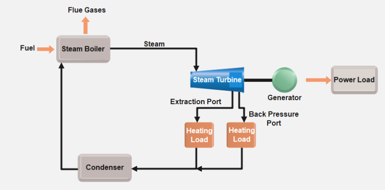
The properties of the steam used in a steam turbine—such as its pressure, temperature, and quality—play a crucial role in determining the turbine’s overall efficiency and performance. Steam is the working fluid in a turbine, and its ability to carry thermal energy for conversion into mechanical work depends on its specific characteristics. Understanding the distinctions between saturated steam, superheated steam, and the importance of steam quality is essential for optimizing turbine operation and ensuring long-term reliability.
Saturated vs. Superheated Steam
There are two primary types of steam used in industrial steam turbines: saturated steam and superheated steam. Each type has distinct characteristics that influence how efficiently energy can be extracted from the steam.
- Saturated Steam:
- Saturated steam is steam that is in equilibrium with liquid water at a given temperature and pressure. This means that the steam contains the maximum amount of energy it can hold at a specific pressure, without being heated beyond its boiling point. Any additional heat input would cause some of the water to vaporize into steam rather than increasing the temperature of the steam itself.
- Properties of Saturated Steam:
- Saturated steam contains both vapor and liquid phases, which can lead to issues such as condensation and moisture buildup during expansion in a turbine.
- It is ideal for applications where both heat and power are needed, such as in cogeneration systems, because the moisture content can be used for industrial heating processes.
- Challenges in Turbine Efficiency:
- In steam turbines, saturated steam can lead to inefficiencies because as it expands, some of the steam may condense back into water. This wet steam can cause blade erosion and reduce turbine efficiency by introducing energy losses due to the presence of liquid droplets.
- Superheated Steam:
- Superheated steam is produced by heating saturated steam beyond its boiling point, at a constant pressure, until it no longer contains any liquid water. Superheated steam is “dry” and has a higher energy content than saturated steam at the same pressure.
- Properties of Superheated Steam:
- Superheated steam has a higher temperature for the same pressure compared to saturated steam, which means it can deliver more energy to the turbine before it condenses.
- It is preferred in most power generation applications because its high thermal energy content allows for greater efficiency during the expansion process in the turbine.
- Advantages for Turbine Efficiency:
- Superheated steam improves the turbine’s thermal efficiency, as it allows for more complete energy extraction without the risk of moisture buildup. Additionally, it minimizes the risk of erosion on the turbine blades, extending the equipment’s lifespan and reducing maintenance requirements.
In most large-scale power generation systems, particularly in fossil-fuel and nuclear power plants, superheated steam is used because it provides higher efficiency and protects the turbine from damage.
Pressure, Temperature, and Steam Quality
The pressure and temperature of the steam entering the turbine significantly affect the turbine’s performance and energy output. Steam quality, which refers to the proportion of vapor in the steam (as opposed to liquid water), is also a critical factor in determining how efficiently the steam transfers energy to the turbine.
- Pressure and Temperature:
- The efficiency of a steam turbine is highly dependent on the inlet steam pressure and temperature. Higher steam pressures and temperatures lead to greater energy content in the steam, which allows for more work to be extracted from the steam as it expands in the turbine.
- High-pressure and High-temperature Steam:
- Modern steam turbines, particularly in power plants, often operate with superheated steam at extremely high pressures (up to 240 bar) and high temperatures (up to 600°C). This increases the amount of energy available for conversion into mechanical work.
- Efficiency Benefits: Higher inlet pressures and temperatures improve the thermal efficiency of the turbine, as more energy is extracted from the steam before it is exhausted or condensed. These turbines can achieve efficiency rates of 40-50% or higher in modern power plants.
- Steam Temperature Control: To prevent damage to turbine blades, it is essential to carefully control the temperature of the steam. Overheating can cause thermal stress and degrade the turbine materials, while steam that is too cool may condense prematurely, leading to moisture-related issues.
- Steam Quality:
- Steam quality refers to the ratio of vapor to liquid in a mixture of steam. A steam quality of 100% means that the steam is completely vapor (dry steam), while a steam quality of less than 100% indicates that some portion of the steam is liquid water.
- Importance of High Steam Quality:
- Steam quality is especially important for maintaining turbine efficiency and protecting turbine components. When steam enters a turbine with a quality lower than 100%, it contains liquid droplets that can cause erosion and pitting of the turbine blades, leading to reduced efficiency and costly repairs.
- For optimal turbine performance, it is crucial to maintain as high a steam quality as possible. This is particularly important in the low-pressure stages of a turbine, where steam tends to condense as it expands and cools.
- Dealing with Wet Steam:
- In some cases, moisture separators or reheat systems are used to reduce the moisture content of the steam. In a reheat cycle, partially expanded steam is returned to the boiler for reheating, which increases its energy content and improves steam quality before it reenters the turbine for further expansion.
Wetness and Steam Moisture Content
Steam moisture content, or the presence of liquid water in the steam, is a critical factor that can have a significant impact on turbine efficiency and longevity. As steam expands in the turbine, its temperature and pressure decrease, causing some of the steam to condense into water droplets. This is especially common in low-pressure turbines, where steam reaches lower temperatures.
- Effects of Wet Steam:
- Efficiency Losses: Wet steam is less efficient at transferring energy to the turbine blades because the liquid droplets do not contribute to the kinetic energy that drives the turbine. As a result, the presence of moisture reduces the overall efficiency of the turbine.
- Blade Erosion: The high-speed liquid droplets in wet steam can cause significant damage to the turbine blades over time. As the droplets collide with the blades, they can cause erosion, pitting, and surface wear, which leads to a decrease in turbine performance and increased maintenance requirements.
- Methods for Managing Steam Moisture:
- Reheat Cycles: One of the most effective methods for reducing steam moisture is the use of reheat cycles. After partial expansion in the high-pressure turbine, the steam is sent back to the boiler for reheating before entering the intermediate- or low-pressure stages. This increases the steam’s temperature and decreases its moisture content, resulting in higher efficiency and reduced wear on the blades.
- Moisture Separators: In some systems, moisture separators are used to remove water droplets from the steam before it enters the turbine or between turbine stages. These devices help to ensure that the steam entering the turbine has minimal moisture content, improving efficiency and reducing the risk of erosion.
Conclusion
The properties of steam—whether it is saturated or superheated, its pressure, temperature, and quality—are critical to the performance and efficiency of industrial steam turbines. Superheated steam, with its higher energy content, is generally preferred in power generation applications for its ability to maximize energy extraction and protect turbine components. Maintaining high steam quality is essential to prevent damage from moisture and ensure that the turbine operates efficiently over the long term. By optimizing steam properties and managing steam moisture content, engineers can enhance turbine performance, reduce maintenance costs, and extend the operational lifespan of the system.
Types of Industrial Steam Turbines
Industrial steam turbines are categorized based on their design, operating principles, and specific applications. While all steam turbines convert the thermal energy of steam into mechanical work, they differ in how they achieve this conversion, the steam conditions they handle, and the industrial processes they support. The main types of industrial steam turbines include impulse and reaction turbines, condensing and non-condensing turbines, as well as more specialized configurations such as back-pressure and extraction turbines.
Each type of steam turbine has its own advantages and is suited to different industrial settings, depending on factors like the need for electricity generation, cogeneration (combined heat and power), or industrial heating. This section explores these types in detail, explaining their working principles and applications.
Impulse vs. Reaction Turbines
One of the fundamental ways to classify steam turbines is by the working principle they use to convert steam energy into mechanical work. The two primary types are impulse turbines and reaction turbines, both of which operate based on different steam flow dynamics.
- Impulse Turbines:
- In an impulse turbine, steam is directed through nozzles, where it undergoes a rapid pressure drop and is converted into high-velocity steam jets. These steam jets are then directed onto the turbine blades, imparting a force that causes the rotor to spin. The energy conversion in an impulse turbine primarily occurs due to the kinetic energy of the steam.
- Working Principle: The nozzles accelerate the steam, increasing its velocity while keeping the pressure relatively constant as it moves across the turbine blades. The force of the high-velocity steam on the turbine blades creates a turning motion.
- Applications: Impulse turbines are often used in high-pressure stages of power plants and industrial processes where the steam enters the turbine at a high pressure. They are well-suited for applications requiring simple designs, such as in marine propulsion and mechanical drives.
- Advantages:
- Impulse turbines can handle high-pressure steam efficiently.
- They are relatively simple to design and maintain.
- Disadvantages:
- Impulse turbines tend to have lower efficiency at low steam velocities or pressures.
- Reaction Turbines:
- In a reaction turbine, the steam expands both in stationary nozzles and as it passes over the blades. In contrast to impulse turbines, where most of the energy conversion happens in the nozzles, reaction turbines extract energy from the steam as it changes both pressure and velocity as it moves through the turbine.
- Working Principle: As the steam moves through the turbine blades, it expands and undergoes a drop in pressure, which generates additional velocity. This gradual expansion and pressure drop allow the turbine to capture more energy from the steam.
- Applications: Reaction turbines are often used in medium- to low-pressure stages in power plants, where the steam expands more gradually. They are also employed in applications where efficiency needs to be maximized over a range of pressures and temperatures.
- Advantages:
- Reaction turbines tend to have higher efficiency at lower steam pressures compared to impulse turbines.
- The smooth expansion of steam results in a more continuous energy extraction process.
- Disadvantages:
- Reaction turbines are more complex in design and require precise control of steam flow and pressure.
Condensing vs. Non-condensing (Back-pressure) Turbines
Steam turbines can also be classified by how they handle exhaust steam after it has passed through the turbine. This leads to the distinction between condensing turbines and non-condensing turbines (also known as back-pressure turbines).
- Condensing Turbines:
- Condensing turbines are designed to maximize energy extraction by condensing the steam into water at the turbine’s exhaust. In these systems, steam is expanded to a very low pressure and temperature in the turbine before entering a condenser, where it is cooled and converted back into liquid water. This process creates a large pressure difference between the inlet and the outlet of the turbine, allowing for maximum energy extraction.
- Applications: Condensing turbines are primarily used in large-scale power generation, particularly in fossil fuel, nuclear, and geothermal power plants, where electricity production is the main goal.
- Advantages:
- Condensing turbines are highly efficient at extracting energy from steam, making them ideal for power generation.
- They are designed to handle low-pressure exhaust steam, which enhances overall energy conversion.
- Disadvantages:
- These turbines require complex systems, including cooling water circuits and condensers, which add to the plant’s cost and complexity.
- Large volumes of cooling water may be required, limiting their use in water-scarce regions.
- Non-condensing (Back-pressure) Turbines:
- In a non-condensing turbine, the steam is not condensed after passing through the turbine. Instead, it is exhausted at a higher pressure, which can be used for further industrial processes, such as heating, drying, or chemical reactions. These turbines are often used in cogeneration systems, where both electricity and heat are needed.
- Applications: Non-condensing turbines are widely used in industries such as chemical plants, refineries, pulp and paper mills, and food processing, where steam is required for both mechanical work and industrial heating.
- Advantages:
- Non-condensing turbines are highly efficient in cogeneration applications since they provide both electricity and heat for industrial processes.
- They are simpler and cheaper to install and maintain than condensing turbines, as they do not require condensers or extensive cooling systems.
- Disadvantages:
- Non-condensing turbines are not as efficient for electricity generation alone, as they extract less energy from the steam compared to condensing turbines.
Back-pressure, Extraction, and Reheat Turbines
Some industrial processes require more specialized steam turbine configurations to balance between electricity generation and heat supply. Back-pressure turbines, extraction turbines, and reheat turbines are tailored to specific industrial needs.
- Back-pressure Turbines:
- Back-pressure turbines exhaust steam at a higher pressure than condensing turbines, allowing the steam to be reused in other industrial processes. This makes them ideal for cogeneration or district heating systems.
- Working Principle: After generating electricity in the turbine, the steam exits at a pressure that is still high enough to be used in heating systems or other industrial processes.
- Applications: These turbines are common in industrial plants that need both mechanical power and steam for heating or processing purposes.
- Extraction Turbines:
- Extraction turbines are designed to extract steam at one or more intermediate stages in the turbine, allowing the steam to be used for industrial processes at different pressures. The remaining steam continues to expand through the turbine to generate more electricity.
- Working Principle: Steam is partially expanded in the turbine, then “extracted” at a desired pressure level for use in processes such as drying, heating, or cooling. The remaining steam continues to expand and generate electricity.
- Applications: Extraction turbines are commonly used in industries such as pulp and paper, petrochemical refining, and chemical manufacturing, where steam is needed at different pressures for various processes.
- Advantages:
- Flexible steam supply at different pressure levels allows the turbine to meet varying process demands.
- They offer a balance between power generation and steam supply for industrial use.
- Reheat Turbines:
- Reheat turbines are used in large power plants to increase the efficiency of the steam cycle. In these turbines, steam is partially expanded in the high-pressure section, then returned to the boiler for reheating before continuing through the intermediate- and low-pressure sections of the turbine.
- Working Principle: The reheat cycle increases the average temperature at which heat is added to the system, improving the overall efficiency of the Rankine cycle. Reheating the steam reduces the risk of condensation in the low-pressure stages, protecting the turbine blades from erosion.
- Applications: Reheat turbines are common in large power plants, particularly in coal, gas, and nuclear power plants, where maximizing efficiency is critical.
- Advantages:
- Reheating increases the efficiency of the turbine and reduces the moisture content of the steam.
- These turbines allow for more energy extraction before the steam is condensed or exhausted.
Conclusion
The various types of industrial steam turbines—whether classified by working principle (impulse vs. reaction) or by application (condensing, non-condensing, extraction, or reheat)—each offer unique advantages depending on the operational requirements. Understanding the specific characteristics of each type allows engineers to select the appropriate turbine for a given application, whether it’s maximizing power generation in a utility-scale power plant or efficiently meeting the needs of an industrial facility that requires both electricity and steam. As industries continue to seek more efficient and sustainable energy solutions, these specialized turbine configurations will remain vital in optimizing energy conversion processes.
Design and Construction of Steam Turbines
The design and construction of steam turbines require precision engineering to ensure high efficiency, reliability, and durability. Steam turbines operate in environments with extreme temperatures and pressures, making material selection, aerodynamic design, and thermal management critical to their performance. This section delves into the major components of a steam turbine, the materials used, key design considerations, and the technological advancements that have led to more efficient and longer-lasting turbines.
Major Components of a Steam Turbine
Steam turbines consist of several critical components, each playing a crucial role in the turbine’s ability to convert steam energy into mechanical work. These components must be designed to withstand the high thermal and mechanical stresses imposed by the steam’s energy and ensure smooth operation over long periods.
- Rotor:
- The rotor is the central rotating shaft of the steam turbine, onto which the turbine blades are mounted. It converts the energy from steam into rotational mechanical energy, which is then used to drive a generator or mechanical load.
- Design and Function: Rotors are designed to be as lightweight as possible while maintaining the strength to withstand the high centrifugal forces generated by the rotating blades. They are typically made from high-strength steel alloys or other advanced materials that resist thermal expansion and mechanical stress.
- Operational Challenges: As the rotor spins at thousands of revolutions per minute (RPM), it must be perfectly balanced to avoid excessive vibration. Even slight imbalances can cause wear on bearings and seals, leading to reduced efficiency and potential mechanical failures.
- Blades:
- The blades, also called buckets in some turbine configurations, are the primary components that interact with the steam. As steam flows through the turbine, it imparts kinetic energy to the blades, causing the rotor to spin. Blades are typically mounted in stages along the rotor, each stage designed to handle specific pressure and temperature conditions.
- Blade Materials: Steam turbine blades are exposed to extreme conditions, including high temperatures, high pressures, and high-velocity steam. To handle these conditions, blades are typically made from high-strength alloys, such as nickel-based superalloys, which retain their strength and resist corrosion at high temperatures. In addition, blades may be coated with special materials to resist erosion and corrosion from steam impurities.
- Blade Design: The shape and aerodynamic design of turbine blades are critical for optimizing efficiency. Engineers use computational fluid dynamics (CFD) to design blades with complex shapes that minimize energy losses due to turbulence and maximize the energy extracted from the steam. Modern turbines use 3D blades with variable angles of attack to ensure smooth and efficient steam flow.
- Casing:
- The casing encloses the turbine and houses the rotor and blades. It serves several important functions, including guiding the steam through the turbine stages and containing the high-pressure steam as it expands and releases energy.
- Materials: The casing is typically made from high-strength steel or cast iron, designed to withstand the thermal expansion and mechanical stresses caused by the high temperatures and pressures of the steam. The casing is often insulated to minimize heat loss and improve thermal efficiency.
- Thermal Expansion: Steam turbines operate at high temperatures, causing the metal components, including the casing, to expand. To prevent mechanical stress or misalignment, casings are designed with expansion joints or made from materials that tolerate thermal expansion without compromising structural integrity.
- Nozzles:
- Nozzles are responsible for directing the flow of high-pressure steam onto the turbine blades. In impulse turbines, the nozzles convert the steam’s pressure energy into kinetic energy by accelerating the steam to high velocities. In reaction turbines, the nozzles are incorporated into the blade design, allowing steam to expand and drop in pressure as it passes through each stage.
- Design Considerations: The shape and orientation of the nozzles are designed to ensure that steam impacts the blades at the correct angle, maximizing energy transfer and minimizing losses. Nozzles are often made from high-strength materials that resist erosion caused by high-velocity steam.
- Bearings:
- Bearings support the rotor and allow it to rotate smoothly at high speeds. Steam turbines use both radial and axial bearings to manage the forces generated by the rotor’s spinning motion.
- Material and Design: Bearings must be designed to handle the high loads and rotational speeds of the turbine while minimizing friction. They are typically made from high-performance materials such as steel alloys or ceramics, and may use oil or magnetic lubrication to reduce wear.
- Vibration Management: Bearings also play a key role in managing vibration, which can occur due to imbalances in the rotor or blade assembly. Advanced bearing systems use vibration-damping materials or designs to reduce mechanical stress and ensure smooth operation.
- Seals:
- Seals are used to prevent steam from escaping from the turbine at the points where the rotor passes through the casing. They are critical for maintaining efficiency, as any steam leakage reduces the amount of energy available for conversion into mechanical work.
- Types of Seals: Common seal types include labyrinth seals, which create multiple obstacles to prevent steam from leaking, and carbon seals, which provide a tighter seal but may wear over time. Seals must be designed to withstand the high temperatures and pressures inside the turbine while minimizing friction and wear.
- Condenser (in Condensing Turbines):
- In condensing turbines, after steam has passed through the turbine, it enters the condenser, where it is cooled and returned to liquid water. The condenser is a crucial component in power generation systems that use the Rankine cycle, as it helps maintain the pressure differential that drives steam flow through the turbine.
- Design: Condensers are usually large heat exchangers that use cooling water or air to remove heat from the exhaust steam. They are designed to maximize heat transfer efficiency while minimizing the amount of cooling water required.
Materials Used in Steam Turbine Construction
The materials used in the construction of steam turbines must withstand extreme temperatures, high pressures, and mechanical stresses. The choice of materials is critical for ensuring the long-term reliability and efficiency of the turbine.
- Nickel-based Alloys:
- Nickel-based superalloys are commonly used for turbine blades and other high-temperature components because of their excellent resistance to heat, oxidation, and creep (slow deformation under stress). These alloys maintain their strength and structural integrity at temperatures exceeding 600°C, making them ideal for use in both high-pressure and low-pressure turbine stages.
- Chromium-based Alloys:
- Chromium-based alloys are often used in turbine blades, rotors, and casings due to their corrosion resistance. Chromium helps form a protective oxide layer on the surface of the metal, preventing oxidation and chemical corrosion caused by the high-temperature steam.
- Steel Alloys:
- High-strength steel alloys are used for structural components such as the rotor, casing, and nozzles. These materials are chosen for their ability to withstand high mechanical stresses and resist fatigue caused by the turbine’s continuous operation.
- Ceramic Coatings:
- In some high-temperature applications, turbine blades are coated with ceramic materials to provide additional thermal protection. Ceramic coatings, also known as thermal barrier coatings (TBCs), protect the underlying metal from the extreme heat of the steam, allowing the turbine to operate at higher temperatures without suffering damage.
Design Considerations for Efficiency and Durability
Several key design considerations ensure that steam turbines operate at maximum efficiency while maintaining long-term durability. These factors include aerodynamic efficiency, thermal management, and minimizing mechanical losses.
- Aerodynamic Blade Design:
- The shape and profile of the turbine blades are critical for maximizing energy extraction from the steam. Engineers use computational fluid dynamics (CFD) to simulate steam flow and optimize the blade design. Modern turbine blades are designed to maintain laminar flow, which reduces turbulence and energy losses.
- 3D Blades: Many modern turbines use 3D blades with variable angles of attack and complex curvatures. These designs allow for better control of steam flow, minimizing energy losses and improving overall efficiency.
- Multi-stage Design:
- Most industrial steam turbines are multi-stage machines, where steam passes through several sets of blades before exiting the turbine. Each stage is designed to extract energy from the steam at different pressure and temperature levels. By using multiple stages, the turbine can extract more energy from the steam, improving efficiency.
- High-Pressure, Intermediate-Pressure, and Low-Pressure Stages: Multi-stage turbines are divided into high-pressure (HP), intermediate-pressure (IP), and low-pressure (LP) sections, with each section optimized for different steam conditions. The combination of these stages allows the turbine to operate efficiently across a wide range of steam pressures.
- Thermal Management and Cooling Systems:
- Efficient thermal management is essential for ensuring the turbine operates at high temperatures without suffering damage. Blade cooling systems are used in high-temperature turbines to prevent overheating and extend the life of the turbine blades.
- Internal Cooling: Many modern turbine blades have internal cooling channels that circulate air or coolant to reduce the temperature of the blades, allowing the turbine to operate at higher inlet temperatures while maintaining durability.
- Vibration Control and Noise Reduction:
- Steam turbines operate at very high rotational speeds, making vibration a significant concern. Excessive vibration can lead to mechanical failures, reduce efficiency, and shorten the turbine’s operational life. Advanced bearing designs, balanced rotors, and vibration-damping systems are used to manage and minimize vibration.
- Noise Reduction: Steam turbines can generate significant noise during operation, particularly at high speeds. Noise-reduction technologies, such as acoustic insulation and vibration-damping materials, are often used to reduce the impact of noise in industrial environments.
Advances in Turbine Technology
Technological advancements in materials, design, and digitalization have significantly improved the performance and efficiency of steam turbines in recent years. Some of the key advancements include:
- 3D Printing and Additive Manufacturing:
- The use of additive manufacturing (3D printing) in turbine construction has enabled the production of complex, high-precision parts that were previously difficult or impossible to manufacture using traditional methods. 3D printing allows for the optimization of blade designs, leading to higher efficiency and reduced manufacturing costs.
- Smart Turbines and Digital Twins:
- Modern turbines are increasingly equipped with sensors that monitor performance in real-time, providing data on temperature, pressure, vibration, and efficiency. This data can be used to predict maintenance needs and optimize turbine operation.
- Digital Twins: The concept of digital twins—virtual models of physical turbines—allows engineers to simulate different operating conditions and optimize turbine performance without disrupting actual operations.
- Advanced Coatings and Materials:
- New materials and coatings are being developed to increase the durability and efficiency of turbine blades. Erosion-resistant coatings and thermal barrier coatings (TBCs) improve the lifespan of components and allow turbines to operate at higher temperatures without suffering from thermal fatigue or corrosion.
Conclusion
The design and construction of steam turbines require a careful balance between maximizing efficiency and ensuring durability. By using advanced materials, precision engineering, and sophisticated design techniques, modern steam turbines are able to operate at high pressures and temperatures while maintaining long-term reliability. As technology continues to evolve, steam turbines will become even more efficient, durable, and adaptable to the changing demands of the energy industry.
Working Stages of a Steam Turbine
In industrial steam turbines, steam passes through several stages before exiting the system, with each stage optimized to extract energy from the steam at varying pressures and temperatures. These stages, known as the high-pressure (HP), intermediate-pressure (IP), and low-pressure (LP) stages, allow the turbine to efficiently convert the maximum amount of thermal energy from the steam into mechanical work. By using multiple stages, turbines achieve higher efficiencies and can handle larger variations in steam conditions, making them ideal for power generation and industrial applications.
This section outlines the working principles of each stage, the design considerations, and how multi-stage designs enhance turbine efficiency.
High-Pressure (HP) Stage
The high-pressure (HP) stage is the first stage in most industrial steam turbines, where steam enters at its highest pressure and temperature. This stage is designed to extract the maximum energy from the steam before it begins to expand and lose pressure.
- Function of the HP Stage:
- Steam enters the HP stage directly from the boiler, often at pressures as high as 200–240 bar and temperatures between 500°C and 600°C in modern power plants. The high temperature and pressure at this stage mean the steam contains a significant amount of thermal energy, which is then converted into mechanical work as it passes through the turbine.
- The blades in the HP stage are designed to handle these extreme conditions and are typically made from advanced materials like nickel-based superalloys that can withstand high temperatures and pressures without degrading.
- Energy Extraction:
- As the high-pressure steam expands through the HP stage, it undergoes a rapid drop in pressure and temperature, converting its enthalpy (thermal energy) into kinetic energy, which drives the turbine blades.
- The high-pressure stage is particularly important because it accounts for a significant portion of the turbine’s overall energy extraction. The high temperature and pressure conditions provide a larger enthalpy drop, which results in more work being done on the turbine blades.
- Design Considerations:
- The blades and nozzles in the HP stage must be carefully designed to maximize energy extraction while minimizing mechanical stress. Since the steam in this stage is at its hottest and most energetic, efficient thermal management is essential to prevent overheating and material fatigue.
- Advanced blade cooling systems may be used in this stage to ensure that the turbine blades remain at safe operating temperatures, even when handling superheated steam.
Intermediate-Pressure (IP) Stage
After passing through the high-pressure stage, the steam moves into the intermediate-pressure (IP) stage, where it continues to expand and lose pressure. The IP stage is designed to extract additional energy from the steam as it cools and decreases in pressure, but still contains significant energy for conversion.
- Function of the IP Stage:
- The steam entering the IP stage has already lost a portion of its pressure and temperature but still contains enough thermal energy to perform mechanical work. Typical steam pressures in the IP stage range from 30 to 80 bar, depending on the specific turbine design and the steam conditions.
- The blades in the IP stage are optimized for handling lower pressures and temperatures compared to the HP stage. As the steam expands further, the size and shape of the turbine blades are adjusted to capture the remaining energy efficiently.
- Energy Extraction:
- The IP stage continues to extract energy from the steam as it expands and loses pressure. Since the temperature and pressure are lower than in the HP stage, the rate of energy extraction is somewhat lower, but it is still critical for the turbine’s overall efficiency.
- In many modern power plants, the IP stage may also include steam reheating, where the steam is sent back to the boiler for reheating before entering the IP turbine. Reheating increases the steam’s temperature without significantly raising its pressure, allowing for more efficient energy extraction while preventing excessive moisture buildup in the later stages of the turbine.
- Design Considerations:
- The design of the IP stage blades is optimized for steam that is cooler and at a lower pressure compared to the HP stage. The blades in this stage are typically larger and have a different aerodynamic profile to accommodate the expanded steam flow.
- In multi-stage turbines, the IP section may contain multiple rows of blades to allow for more gradual steam expansion, ensuring that as much energy as possible is extracted before the steam moves to the low-pressure stage.
Low-Pressure (LP) Stage
The low-pressure (LP) stage is the final stage in most steam turbines, where the steam expands to its lowest pressure and temperature. By the time the steam reaches the LP stage, much of its energy has already been extracted, but there is still residual energy that can be converted into mechanical work.
- Function of the LP Stage:
- The LP stage is designed to handle steam at significantly lower pressures, often in the range of 0.05 to 5 bar, and at temperatures closer to the boiling point of water. In some cases, the steam may even reach near-vacuum conditions in the LP stage to maximize energy extraction.
- The LP stage typically features the largest blades in the turbine, as the steam expands and occupies a much larger volume. These large blades are necessary to capture the remaining energy from the low-pressure steam.
- Energy Extraction:
- While the energy extraction in the LP stage is lower compared to the HP and IP stages, it is still a critical part of the overall process. The steam is now at a much lower pressure and temperature, meaning that the turbine must efficiently capture the remaining energy before the steam is exhausted.
- In condensing turbines, the LP stage is connected to a condenser, where the steam is cooled and condensed back into liquid water. This creates a vacuum at the turbine exhaust, which helps to increase the pressure differential across the LP stage and improve efficiency.
- Design Considerations:
- The blades in the LP stage must be designed to handle the large volumes of low-pressure steam, which expands significantly as it cools. These blades are usually the longest in the turbine and are made from materials that can withstand the mechanical stresses of spinning at high speeds while handling large steam volumes.
- Moisture control is critical in the LP stage, as the steam may begin to condense into water droplets as it cools. Excess moisture can cause blade erosion and reduce the efficiency of the turbine. To mitigate this, moisture separators or reheat systems may be used to maintain the steam quality.
Multi-stage Designs for Efficiency
Modern industrial steam turbines use multiple stages to maximize energy extraction and improve efficiency. Each stage (HP, IP, and LP) is carefully designed to handle the specific pressure and temperature conditions of the steam as it progresses through the turbine.
- Advantages of Multi-stage Designs:
- Increased Efficiency: Multi-stage turbines allow for more complete energy extraction by using different blade designs for high-, medium-, and low-pressure steam. This ensures that as much energy as possible is converted into mechanical work.
- Improved Flexibility: Multi-stage turbines can handle a wide range of steam conditions, making them ideal for large power plants and industrial systems that operate at varying loads and steam qualities.
- Better Steam Quality Control: By using reheat cycles and moisture separators between stages, multi-stage turbines can maintain high steam quality and minimize the risk of moisture-related issues like blade erosion.
- Reheat Cycles:
- In many large-scale turbines, particularly those used in power plants, a reheat cycle is used to improve efficiency. After the steam passes through the HP stage, it is sent back to the boiler to be reheated before entering the IP stage. This reheating process increases the steam’s temperature without significantly increasing its pressure, allowing for more efficient energy extraction in the later stages.
Conclusion
The working stages of a steam turbine—high-pressure, intermediate-pressure, and low-pressure—are designed to extract the maximum amount of energy from steam as it expands and loses pressure. Each stage plays a critical role in ensuring that the turbine operates efficiently, converting as much thermal energy as possible into mechanical work. Multi-stage designs, combined with reheat cycles and moisture management, ensure that steam turbines can operate efficiently and reliably in a wide range of industrial and power generation applications.
Condensing Turbines
Condensing turbines are a type of steam turbine used primarily in power generation, where the goal is to maximize the extraction of energy from steam. In these turbines, steam is expanded to a low pressure and then condensed back into water using a condenser. The purpose of condensing the steam is to create a large pressure difference across the turbine, which helps to maximize the amount of energy extracted from the steam. The condensed water is then pumped back to the boiler to restart the cycle.
Importance in Industrial Power Generation
Condensing turbines are critical in large-scale power plants, especially those fueled by coal, natural gas, oil, or nuclear energy. They are highly efficient at converting thermal energy into mechanical work, making them ideal for power plants where the primary objective is electricity generation. Unlike back-pressure or extraction turbines, which may also produce heat for industrial processes, condensing turbines focus on electricity production by condensing steam into water to achieve the lowest possible pressure at the turbine outlet.
Historical Background and Evolution
The evolution of steam turbines began with early steam engines, which were inefficient and bulky. The invention of the steam turbine by Sir Charles Parsons in 1884 revolutionized power generation by introducing a far more efficient method of converting steam energy into electricity. Over the years, condensing turbines have become a staple in power plants, evolving with advancements in materials, design, and technology to handle higher pressures and temperatures, resulting in more efficient power generation.
Basic Overview of Function and Applications
In a condensing turbine, high-pressure steam is directed into the turbine’s high-pressure stage, where it expands and transfers energy to the rotating blades. As the steam moves through successive stages—intermediate and low-pressure stages—it continues to expand, losing pressure and temperature. Finally, the steam enters a condenser, where it is cooled and condensed back into water. This process enables the turbine to maximize energy extraction, making condensing turbines ideal for power plants that focus solely on electricity generation.
Working Principles of Condensing Turbines
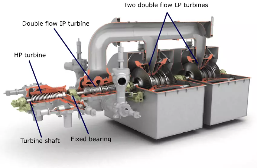
The working principle of condensing turbines is based on the Rankine cycle, a thermodynamic cycle that describes how heat is converted into mechanical work. In this cycle, water is heated to produce steam, which is then expanded through a turbine to generate mechanical energy. After passing through the turbine, the steam is condensed back into water, completing the cycle.
- Heat Addition: Water is heated in a boiler to create steam.
- Expansion: The steam is expanded through the turbine, converting thermal energy into mechanical work.
- Condensation: The steam is condensed in a condenser, reducing its volume and pressure.
- Pressurization: The condensed water is pumped back to the boiler to restart the process.
The key difference between condensing turbines and other steam turbines lies in the condenser, which allows the steam to be cooled and condensed, creating a low-pressure environment that enhances the efficiency of energy extraction.
Energy Conversion: From Steam to Mechanical Work
In condensing turbines, steam enters the turbine at high pressure and temperature, and as it expands through the turbine blades, its energy is converted into rotational mechanical energy. The rotor spins at high speeds, driving a generator to produce electricity. The energy conversion process is highly efficient because the condenser allows for a large pressure differential between the steam entering and exiting the turbine, ensuring that as much energy as possible is extracted.
Role of the Condenser in Pressure Differentials
The condenser plays a critical role in condensing turbines by maintaining a low-pressure environment at the turbine’s exhaust. The steam is cooled in the condenser, typically by water or air, and condensed back into liquid form. This process creates a vacuum at the turbine’s exit, which increases the pressure differential across the turbine stages, allowing for maximum energy extraction from the steam.
How Condensing Turbines Maximize Energy Extraction
By condensing the steam after it has passed through the turbine, condensing turbines can operate with a greater pressure differential than non-condensing turbines. This allows them to extract more energy from the steam, improving the overall efficiency of the power generation process. Condensing turbines are designed to handle large volumes of steam at varying pressures and temperatures, and their multi-stage design ensures that energy is extracted efficiently at every point in the expansion process.
Design of Condensing Turbines
Key Components: Rotor, Blades, Nozzles, Condenser, Bearings, and Seals
The design of condensing turbines involves several key components that work together to efficiently convert thermal energy into mechanical work.
- Rotor: The central shaft of the turbine, which rotates as steam passes over the blades. The rotor is made from high-strength alloys designed to withstand high rotational speeds and thermal stresses.
- Blades: The turbine blades extract energy from the steam by converting its kinetic energy into rotational motion. The blades are designed to handle high-pressure, high-temperature steam and are typically made from corrosion- and heat-resistant alloys.
- Nozzles: In the impulse stages of the turbine, nozzles direct high-velocity steam onto the blades, maximizing energy transfer. The nozzles are designed to minimize pressure loss and optimize the flow of steam through the turbine.
- Condenser: The condenser is one of the most critical components in a condensing turbine. It cools the exhaust steam and condenses it back into liquid water, creating a low-pressure environment that increases the turbine’s efficiency.
- Bearings and Seals: Bearings support the rotor and ensure smooth operation at high speeds, while seals prevent steam leakage, ensuring that the system operates at maximum efficiency.
Materials and Construction
Condensing turbines are constructed from materials that can withstand the high temperatures, pressures, and stresses of steam expansion. Common materials include high-strength steel for the rotor, nickel-based superalloys for the blades, and corrosion-resistant materials for the condenser and other components exposed to steam and water. These materials ensure long-term durability and resistance to wear and tear.
Aerodynamic Blade Design for Efficiency
The design of turbine blades plays a critical role in maximizing the efficiency of condensing turbines. Blades are shaped to minimize turbulence and maximize the conversion of steam’s kinetic energy into rotational energy. Advanced computational fluid dynamics (CFD) is used to design blades that optimize steam flow through the turbine, reducing energy losses and improving overall performance.
Turbine Stages: High-pressure, Intermediate-pressure, and Low-pressure
Condensing turbines are typically multi-stage machines, with steam passing through high-pressure (HP), intermediate-pressure (IP), and low-pressure (LP) stages. Each stage is optimized to extract energy from the steam as it expands and loses pressure:
- High-pressure stage: Handles high-temperature, high-pressure steam from the boiler.
- Intermediate-pressure stage: Expands the steam further, extracting additional energy as pressure and temperature decrease.
- Low-pressure stage: Extracts the remaining energy from the steam before it is condensed in the condenser.
Condenser Design and Function
The condenser in a condensing turbine is designed to maximize heat transfer between the steam and the cooling medium (water or air). Efficient condenser design ensures that the steam is cooled rapidly and condensed back into liquid water, creating a vacuum that improves turbine efficiency. Condensers can be water-cooled or air-cooled, depending on the availability of cooling resources.
Steam Properties and Their Effect on Performance
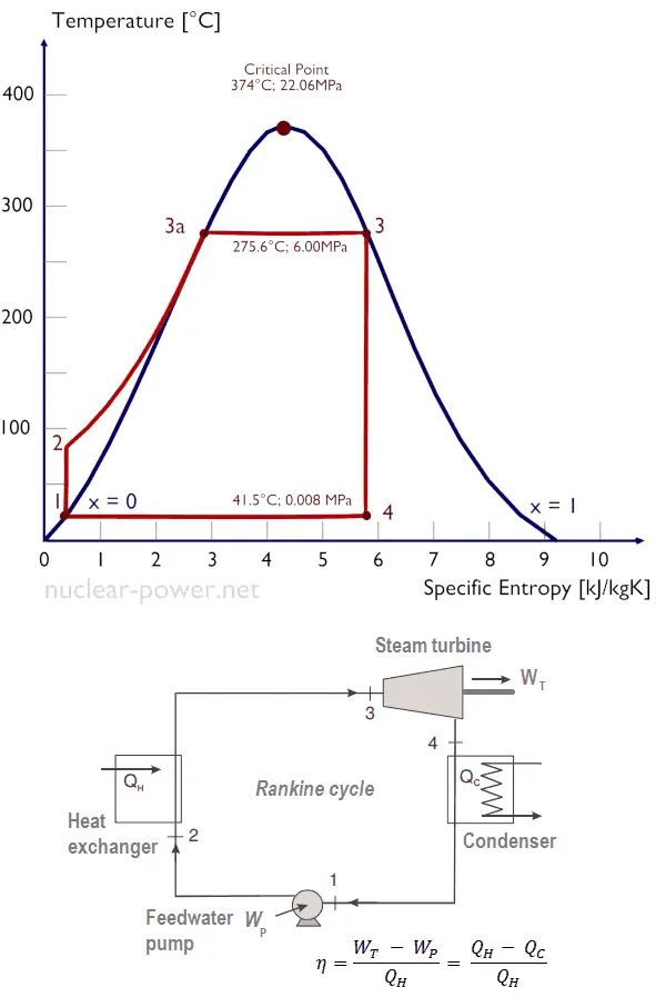
The performance of condensing turbines is heavily influenced by the properties of the steam used in the system. Superheated steam, which has been heated beyond its boiling point at a given pressure, is preferred in condensing turbines because it contains more thermal energy and reduces the risk of condensation during expansion. Saturated steam, which contains both liquid and vapor phases, can lead to efficiency losses and blade erosion due to moisture content.
Pressure, Temperature, and Steam Quality in Condensing Turbines
The pressure and temperature of the steam entering the turbine significantly impact its efficiency. High-pressure, high-temperature steam allows for greater energy extraction, as the pressure differential between the inlet and outlet is maximized. Steam quality, which refers to the ratio of vapor to liquid in the steam, must also be carefully controlled to ensure efficient operation. High-quality steam (dry steam) ensures that more energy is available for conversion into mechanical work.
Dealing with Wet Steam and Moisture Control
As steam expands through the turbine, its temperature and pressure decrease, leading to condensation and the formation of wet steam. Moisture in the steam can cause blade erosion and reduce the turbine’s efficiency. To manage this, modern condensing turbines use moisture separators and reheat systems to ensure that the steam remains as dry as possible throughout the expansion process.
How Steam Properties Influence Efficiency and Blade Erosion
Steam properties such as temperature, pressure, and quality directly affect turbine efficiency. Superheated steam allows for more energy extraction, while wet steam can lead to mechanical wear and tear. Blade erosion from moisture is a common issue in condensing turbines, but this can be mitigated with advanced materials and coatings that protect the blades from wear. Optimizing steam properties is essential for maintaining high turbine efficiency and reducing maintenance costs.
Applications in Power Generation
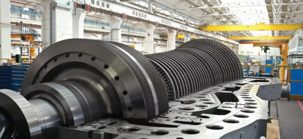
Condensing turbines play a vital role in fossil-fuel power plants, where they are used to convert the thermal energy from burning fuels like coal, natural gas, and oil into electricity. In these plants, steam is generated in a boiler by burning fuel, and the high-pressure steam is directed into the turbine. Condensing turbines are ideal for fossil-fuel plants because they maximize energy extraction by condensing the steam after it has passed through the turbine, allowing for more efficient electricity production.
- Coal-fired Power Plants: Condensing turbines are commonly used in coal-fired power plants, where steam is generated by burning coal in large boilers. These turbines extract the maximum amount of energy from the high-temperature steam, ensuring efficient electricity generation. The use of condensing turbines in coal plants has been a key factor in improving their efficiency and reducing emissions.
- Natural Gas and Combined-cycle Power Plants: In combined-cycle power plants, condensing turbines are used in conjunction with gas turbines to improve overall plant efficiency. The exhaust heat from the gas turbine is used to generate steam, which is then expanded through the condensing turbine to produce additional electricity. This dual-turbine system allows for significantly higher efficiency compared to traditional power plants.
Nuclear Power Plant Applications
Condensing turbines are critical in nuclear power plants, where they convert the heat generated by nuclear fission into electricity. In a nuclear reactor, heat is produced when uranium or other nuclear fuels undergo fission. This heat is used to generate steam, which is directed into the condensing turbine. Due to the immense amounts of heat produced by nuclear reactions, condensing turbines are designed to handle large volumes of steam at high pressures, making them ideal for maximizing energy extraction in nuclear plants.
Use in Combined-cycle Plants
Combined-cycle power plants integrate both gas and steam turbines to improve efficiency. In these plants, a gas turbine generates electricity by burning natural gas, and the hot exhaust gases from the gas turbine are used to produce steam for the condensing turbine. This combined approach increases the overall efficiency of the power plant, often exceeding 60%, making combined-cycle plants one of the most efficient forms of electricity generation.
Integration with Renewable Energy (Biomass and Geothermal)
Condensing turbines are also used in renewable energy applications, particularly in biomass and geothermal power plants. In a biomass plant, organic materials such as wood chips, agricultural waste, or dedicated energy crops are burned to produce steam, which is then expanded through the condensing turbine to generate electricity. In geothermal plants, steam is produced by tapping into geothermal reservoirs beneath the Earth’s surface. Condensing turbines in these plants convert the steam from the hot water or steam reservoirs into electricity, providing a sustainable energy source.
Large-scale Power Plants vs. Distributed Generation
Condensing turbines are predominantly used in large-scale power plants, where their ability to efficiently extract energy from steam makes them ideal for centralized electricity generation. However, advances in turbine technology have led to the development of smaller, more efficient condensing turbines that can be used in distributed generation applications. These turbines are used in industrial facilities and smaller power plants to generate electricity on-site, reducing the need for large-scale infrastructure and improving energy efficiency.
Advantages of Condensing Turbines
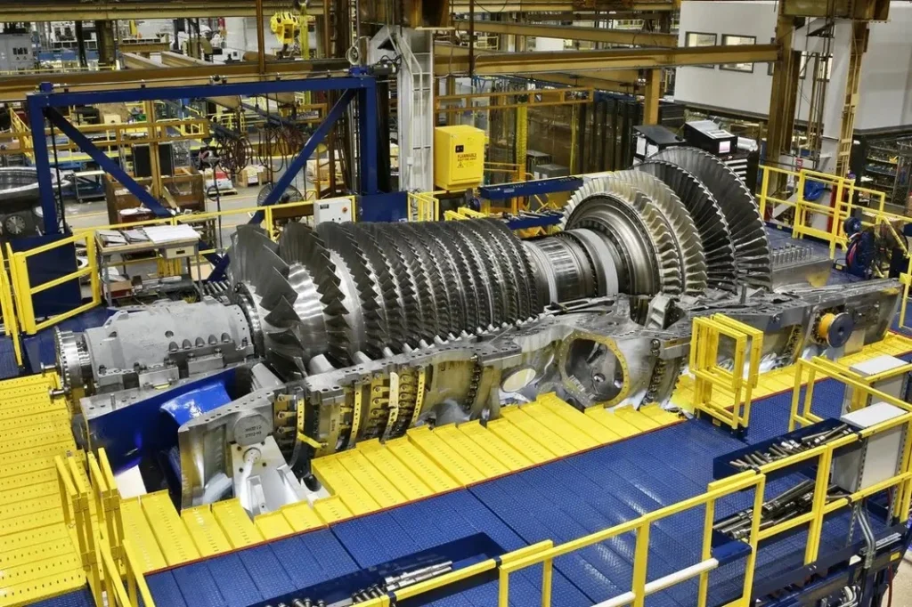
Condensing turbines are among the most efficient types of steam turbines, thanks to their ability to maximize energy extraction from steam. By condensing the steam after it has passed through the turbine, these systems create a large pressure differential between the inlet and outlet, ensuring that as much energy as possible is converted into mechanical work. This makes condensing turbines ideal for applications where electricity generation is the primary objective.
Maximizing Power Output in Power Plants
In large power plants, condensing turbines are used to maximize the amount of electricity produced from a given amount of fuel. By condensing the steam, these turbines allow for more complete energy extraction, leading to higher power output and improved overall efficiency. This is particularly important in fossil-fuel and nuclear power plants, where efficiency gains can significantly reduce fuel consumption and emissions.
Flexibility in Handling Different Steam Conditions
Condensing turbines are designed to handle a wide range of steam conditions, from superheated steam at high pressure to wet steam at lower pressures. This flexibility allows them to be used in various applications, from traditional power plants to renewable energy systems. In particular, condensing turbines are well-suited to combined-cycle plants, where they must handle steam at different temperatures and pressures produced by gas turbine exhaust heat.
Environmental Benefits through Efficiency Improvements
By maximizing the efficiency of electricity generation, condensing turbines help reduce the environmental impact of power plants. Higher efficiency means less fuel is needed to produce the same amount of electricity, leading to lower carbon dioxide (CO₂) emissions and reduced fuel consumption. In addition, the use of condensing turbines in combined-cycle and biomass power plants supports the transition to cleaner energy sources, helping to mitigate climate change.
Challenges and Limitations
One of the main challenges associated with condensing turbines is their dependence on cooling systems to condense the steam after it has passed through the turbine. Water-cooled condensers are commonly used, but they require large amounts of water, which may not be available in all locations. Air-cooled condensers can be used in areas with limited water resources, but they are generally less efficient than water-cooled systems and may require larger infrastructure.
Environmental Challenges: Water Use and Thermal Pollution
The use of large quantities of water for cooling in condensing turbines can lead to environmental issues, including thermal pollution, where heated water is discharged into nearby bodies of water, raising the temperature and potentially harming aquatic ecosystems. Water use in cooling systems also presents a challenge in water-scarce regions, where the availability of cooling water may limit the operation of condensing turbines.
Mechanical Wear and Tear from Wet Steam
As steam expands through the turbine, it can condense into water droplets, leading to wet steam in the later stages of the turbine. This wet steam can cause mechanical wear and tear on the turbine blades, leading to blade erosion and reduced efficiency over time. Managing steam moisture and minimizing blade erosion are ongoing challenges in the operation of condensing turbines.
Blade Erosion and Maintenance Challenges
Blade erosion from moisture in the steam is one of the most common maintenance issues in condensing turbines. Over time, the impact of water droplets on the blades can cause pitting and erosion, reducing the efficiency of the turbine and requiring costly repairs. Modern turbines use advanced materials and coatings to reduce the impact of erosion, but regular maintenance is still necessary to ensure long-term performance.
Performance Monitoring and Efficiency Improvements
Modern condensing turbines are equipped with real-time performance monitoring systems that track key operating parameters such as temperature, pressure, vibration, and steam quality. These systems allow operators to monitor turbine performance and identify potential issues before they lead to equipment failure. By using real-time data, operators can optimize turbine performance and improve overall efficiency.
Digitalization and AI-driven Maintenance
Advances in digitalization and artificial intelligence (AI) are transforming the way condensing turbines are maintained and operated. AI-driven maintenance systems use data from sensors to predict when components are likely to fail, allowing operators to perform maintenance before a breakdown occurs. This approach, known as predictive maintenance, reduces downtime and improves the reliability of condensing turbines.
Efficiency Optimization through Design Improvements
Continued improvements in turbine design are helping to increase the efficiency of condensing turbines. Advances in blade design, aerodynamics, and materials science have led to turbines that can operate at higher temperatures and pressures, improving the efficiency of energy extraction. By optimizing turbine components and reducing energy losses, modern condensing turbines achieve higher efficiencies than older models.
Retrofitting Older Turbines with Modern Technology
Many older condensing turbines can be retrofitted with modern technology to improve their efficiency and performance. Retrofitting options include upgrading turbine blades to more aerodynamic designs, installing advanced cooling systems, and integrating digital monitoring tools. These retrofits can extend the lifespan of older turbines and improve their efficiency, reducing the need for new equipment and lowering operating costs.
Future Trends and Innovations in Condensing Turbines
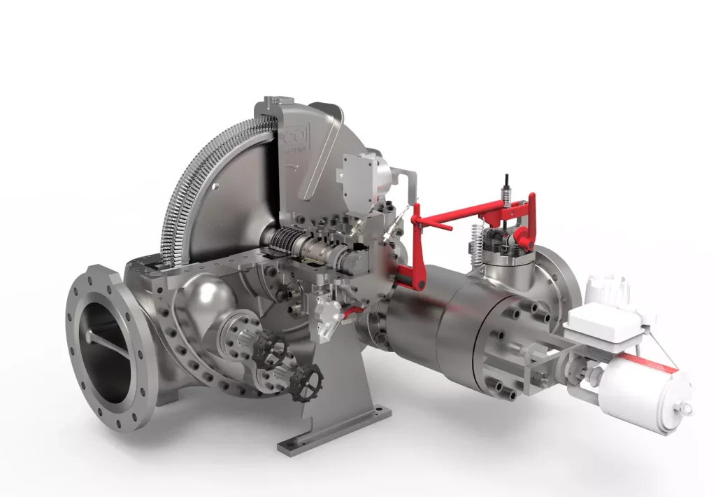
The development of new blade materials and coatings is one of the most exciting areas of innovation in condensing turbines. Advanced materials, such as nickel-based superalloys and ceramic coatings, are allowing turbines to operate at higher temperatures and pressures without suffering from corrosion or erosion. These materials improve the efficiency and durability of turbine blades, reducing the need for frequent maintenance.
Role of Digital Twins and Predictive Analytics
The use of digital twins—virtual models of physical systems—is revolutionizing turbine operation and maintenance. By creating a digital twin of a condensing turbine, operators can simulate different operating conditions and optimize turbine performance without disrupting real-world operations. Predictive analytics tools use data from the digital twin to identify potential performance issues and recommend adjustments, improving turbine efficiency and reliability.
Integration with Renewable and Sustainable Energy Solutions
Condensing turbines are increasingly being integrated into renewable energy systems, such as biomass and geothermal power plants. By using steam generated from renewable sources, these turbines help reduce reliance on fossil fuels and support the transition to cleaner energy. In addition, condensing turbines are being used in conjunction with carbon capture and storage (CCS) technologies to reduce the carbon emissions from fossil-fuel power plants, helping to mitigate climate change.
Future Prospects for Carbon Capture and Storage (CCS)
As the world moves toward reducing carbon emissions, condensing turbines will play a key role in carbon capture and storage (CCS) systems. CCS technology captures carbon dioxide (CO₂) emissions from power plants and industrial facilities and stores them underground, preventing them from entering the atmosphere. Condensing turbines, with their high efficiency and ability to operate at large scales, are well-suited to CCS applications, making them a critical technology in the fight against climate change.
Hybrid Systems and Energy Storage Integration
The future of condensing turbines may also involve greater integration with hybrid energy systems and energy storage technologies. By combining condensing turbines with battery storage or hydrogen production, power plants can store excess energy generated during periods of low demand and release it when demand increases. This approach improves grid stability and allows for more efficient use of renewable energy sources.
Conclusion
Condensing turbines remain a cornerstone of power generation, thanks to their high efficiency and ability to extract maximum energy from steam. From their historical development to their modern applications in fossil-fuel, nuclear, and renewable power plants, condensing turbines continue to evolve with advances in materials, digital technology, and energy storage. Their role in future energy systems, particularly in carbon capture and hybrid energy solutions, will be critical as the world transitions to a more sustainable energy future.
Non-condensing (Back-pressure) Turbines
Non-condensing turbines, also known as back-pressure turbines, are a type of steam turbine where the exhaust steam is released at a pressure higher than atmospheric pressure and is used for industrial processes or heating. Unlike condensing turbines, which maximize energy extraction by condensing the steam into water after it passes through the turbine, back-pressure turbines allow the steam to be used in other parts of the plant.
These turbines are typically employed in combined heat and power (CHP) systems, where steam is required for both electricity generation and industrial processes. The “back pressure” refers to the residual pressure of the steam after it has passed through the turbine, which is then used in heating, drying, or mechanical processes in industries such as petrochemicals, food processing, and pulp and paper manufacturing.
Basic Function and Operation
Non-condensing turbines operate by using steam at high pressure to drive a turbine, converting thermal energy into mechanical energy. After passing through the turbine, the steam is exhausted at a lower pressure, but still contains sufficient energy to be used in downstream processes. This configuration allows industries to extract both power and heat from the same steam source, making back-pressure turbines ideal for cogeneration applications, where both power and process heat are required.
Historical Development
The use of steam turbines dates back to the late 19th century when Sir Charles Parsons developed the first practical steam turbine. Non-condensing turbines have evolved alongside their condensing counterparts, finding niche applications in industries that require both steam and power. Over time, advancements in turbine materials, blade design, and thermodynamics have led to more efficient and reliable back-pressure turbines that are crucial to various industrial processes today.
Importance in Industrial Applications
Non-condensing turbines play a vital role in industries where steam is needed for processes like heating, chemical reactions, or mechanical work, as well as electricity generation. They are commonly used in:
- Cogeneration Plants: Producing both electricity and heat for industrial processes.
- District Heating: Providing steam for heating buildings in cities and industrial complexes.
- Industries like Pulp and Paper, Food Processing, and Petrochemicals: Where both power and steam are required for operations.
Their ability to maximize energy efficiency by utilizing the steam for multiple purposes makes them indispensable in sectors aiming to reduce energy costs and environmental impact.
Working Principles of Non-condensing Turbines
The working principle of non-condensing turbines is based on the Rankine cycle, a thermodynamic cycle that describes how heat is converted into mechanical work. In a non-condensing turbine system, water is heated to generate steam, which expands through the turbine, converting thermal energy into mechanical energy. Unlike in condensing turbines, the steam in a back-pressure turbine is not cooled and condensed but is exhausted at a pressure that can be used for other processes.
- Heat Addition: Water is heated in a boiler, converting it into steam.
- Expansion in the Turbine: The high-pressure steam is expanded in the turbine, doing work as it drives the turbine blades.
- Exhaust at Back Pressure: The steam exits the turbine at a higher pressure than in condensing systems, making it useful for industrial processes that require heat.
Role of Pressure and Temperature
The efficiency of a non-condensing turbine is largely dependent on the pressure and temperature of the steam entering and exiting the turbine. The higher the pressure of the incoming steam, the more energy it carries for conversion into mechanical work. The “back pressure,” or exhaust pressure, is usually set to meet the needs of downstream industrial processes, such as heating or chemical reactions.
Energy Conversion: From Steam to Mechanical Work
In a back-pressure turbine, energy is extracted from the steam by converting its thermal energy into mechanical work. As the steam expands through the turbine stages, it loses pressure and temperature, transferring its energy to the turbine rotor, which spins and generates mechanical power. This power can then be used to drive machinery or generate electricity. Unlike condensing turbines, the steam is not fully exhausted; it retains enough energy to be used in other industrial processes.
Comparison with Condensing Turbines
Compared to condensing turbines, non-condensing turbines offer greater efficiency in situations where both steam and power are needed. Condensing turbines focus on maximizing power generation by extracting as much energy as possible from the steam, while back-pressure turbines prioritize process steam for industrial use. The choice between condensing and non-condensing turbines depends on the specific energy and process needs of the facility. In applications where heat and power are required, back-pressure turbines provide a more efficient solution by minimizing wasted energy.
Key Components and Design of Non-condensing Turbines
Non-condensing turbines are composed of several key components that ensure their efficient operation and long-term durability:
- Rotor: The central shaft of the turbine, connected to the generator or mechanical system. The rotor converts the energy from steam into rotational mechanical work.
- Blades: Turbine blades extract energy from the steam, causing the rotor to spin. These blades are carefully designed to handle varying steam conditions and are typically made from heat- and corrosion-resistant materials.
- Nozzles: Nozzles direct the flow of high-pressure steam onto the turbine blades, maximizing energy transfer.
- Bearings: Bearings support the rotor and allow it to spin at high speeds with minimal friction. These components are essential for maintaining the turbine’s efficiency and preventing mechanical wear.
- Seals: Seals prevent steam leakage, ensuring that the system operates at maximum efficiency. They also play a role in maintaining pressure balance within the turbine.
Back-pressure Stage Design and Optimization
The design of a back-pressure turbine must account for the specific pressure requirements of the exhaust steam. This means optimizing the turbine stages to ensure that the steam exits at the desired back pressure, while still extracting sufficient energy for mechanical work. The size and shape of the turbine blades are optimized to ensure smooth and efficient steam expansion, minimizing losses due to turbulence and inefficiencies in the flow.
Materials Used in Construction
Non-condensing turbines are built from materials that can withstand high temperatures, pressures, and corrosive environments. Nickel-based alloys and stainless steel are commonly used for turbine blades and rotors due to their ability to maintain strength and resist oxidation at high temperatures. Additionally, specialized coatings may be applied to turbine blades to prevent corrosion and erosion caused by steam impurities.
Blade Design for Performance and Durability
The design of the blades in a non-condensing turbine is critical for optimizing performance and ensuring durability. Blades are shaped to maximize the energy extracted from steam while minimizing the mechanical stress placed on the rotor. Aerodynamic design is essential for reducing turbulence and improving efficiency. Modern blade designs also incorporate materials that resist erosion from wet steam, which can damage the blades over time.
Steam Properties and Their Role in Performance
The performance of non-condensing turbines is heavily influenced by the properties of the steam used in the system. Superheated steam is often preferred because it contains more thermal energy and reduces the risk of condensation during expansion. However, saturated steam is sometimes used, depending on the specific requirements of the industrial process.
- Superheated Steam: Steam that has been heated beyond its boiling point at a given pressure. It has a higher energy content and is less likely to condense into water during expansion, which can improve efficiency.
- Saturated Steam: Steam that exists at the boiling point for its pressure. It contains both liquid and vapor phases, which can lead to moisture in the turbine and potential erosion of the blades.
Importance of Pressure and Temperature in Back-pressure Turbines
The pressure and temperature of the steam entering the turbine have a significant impact on the turbine’s performance. Higher-pressure, higher-temperature steam allows for more energy extraction, as the steam carries more thermal energy that can be converted into mechanical work. The back pressure, or exhaust pressure, must be carefully controlled to ensure that the steam can be used effectively in downstream industrial processes.
Managing Steam Quality and Moisture
In non-condensing turbines, maintaining the quality of the steam is essential for ensuring efficiency and minimizing mechanical wear. Wet steam, which contains water droplets, can cause erosion of the turbine blades, reducing efficiency and leading to maintenance issues. To address this, modern turbines use moisture separators or superheating systems to ensure that the steam remains dry throughout the expansion process.
Impact on Efficiency and Equipment Life
The properties of the steam directly influence the efficiency of the turbine and the longevity of its components. Superheated steam tends to increase efficiency by allowing more complete energy extraction, while saturated steam may lead to moisture-related issues. Properly managing steam quality and ensuring that the turbine operates within its design limits helps maximize efficiency and extend the lifespan of the equipment.
Applications of Non-condensing Turbines
One of the most important applications of non-condensing turbines is in cogeneration, also known as Combined Heat and Power (CHP) systems. In these systems, non-condensing turbines are used to produce both electricity and steam for industrial processes. The exhaust steam from the turbine is used to provide heat for industrial applications, such as drying, heating, or chemical reactions, while the turbine generates electricity for on-site use or distribution to the grid.
Cogeneration is highly efficient because it makes use of both the electrical and thermal energy generated from steam, reducing fuel consumption and lowering overall energy costs. Industries such as pulp and paper, food processing, and chemical manufacturing commonly use cogeneration systems with non-condensing turbines.
Use in Petrochemical Refineries, Pulp and Paper Mills, and Food Processing
Non-condensing turbines are widely used in petrochemical refineries, pulp and paper mills, and food processing plants, where both electricity and steam are needed for industrial processes. In these industries, back-pressure turbines provide a flexible and efficient solution for meeting the energy demands of the plant.
- Petrochemical Refineries: In petrochemical refineries, steam is used to drive compressors, pumps, and other equipment. The exhaust steam from non-condensing turbines is often used for heating or chemical processes within the refinery.
- Pulp and Paper Mills: In the pulp and paper industry, steam is required for both drying paper and generating electricity. Non-condensing turbines allow mills to produce power while also supplying steam for drying processes, improving overall energy efficiency.
- Food Processing: Food processing plants use steam for cooking, sterilization, and drying. Non-condensing turbines generate electricity while providing the steam necessary for these operations, allowing the plant to reduce energy costs and improve operational efficiency.
District Heating Systems
In district heating systems, non-condensing turbines provide steam for heating large industrial complexes, residential areas, or entire cities. The exhaust steam from the turbine is distributed through a network of pipes to provide heating for buildings, reducing the need for individual heating systems. Non-condensing turbines are ideal for district heating applications because they can provide both electricity and heating from a single source of energy, improving the overall efficiency of the system.
Integration in Power Plants and Energy Systems
Non-condensing turbines are used in power plants where both electricity generation and steam for industrial processes are required. In combined-cycle power plants, for example, non-condensing turbines are used alongside gas turbines to maximize efficiency. The gas turbine generates electricity, while the waste heat from the gas turbine is used to produce steam, which is expanded through the non-condensing turbine to generate additional electricity and provide steam for industrial processes.
Renewable Energy: Biomass and Geothermal Applications
Non-condensing turbines are also used in renewable energy applications, particularly in biomass and geothermal power plants. In biomass plants, organic materials such as wood chips, agricultural waste, or dedicated energy crops are burned to produce steam, which is expanded through a non-condensing turbine to generate electricity. The exhaust steam is then used for heating or other industrial processes.
In geothermal power plants, steam is produced by tapping into geothermal reservoirs beneath the Earth’s surface. The steam is expanded through a non-condensing turbine to generate electricity, and the remaining heat can be used for district heating or industrial applications. Non-condensing turbines in renewable energy systems help maximize the use of available resources, improving overall efficiency and reducing environmental impact.
Advantages of Non-condensing Turbines
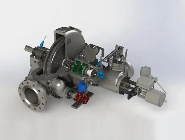
Non-condensing turbines are highly efficient in cogeneration systems because they make use of both the electrical and thermal energy produced from steam. By using the exhaust steam for industrial processes or heating, cogeneration systems with back-pressure turbines achieve higher overall efficiencies compared to systems that generate only electricity. This dual-use of steam reduces fuel consumption and lowers energy costs for industries that require both power and process steam.
Flexibility in Steam and Power Output
One of the key advantages of non-condensing turbines is their flexibility. They can be used in a variety of applications, from generating electricity to providing steam for industrial processes. This flexibility allows industries to optimize their energy use based on their specific needs, whether they require more electricity or more steam. Additionally, the back pressure of the turbine can be adjusted to meet the requirements of downstream processes, ensuring that the system operates at maximum efficiency.
Reduced Environmental Impact
By improving energy efficiency, non-condensing turbines help reduce the environmental impact of industrial processes. Cogeneration systems with non-condensing turbines use less fuel to produce the same amount of energy, resulting in lower carbon dioxide (CO₂) emissions and reduced fuel consumption. In industries where both power and process heat are required, non-condensing turbines offer a more sustainable and cost-effective solution compared to traditional power generation methods.
Operational Benefits and Cost Efficiency
Non-condensing turbines provide several operational benefits, including lower energy costs and improved system efficiency. By generating electricity and process steam from the same steam source, these turbines help industries reduce their reliance on external energy sources, lowering fuel costs and improving operational efficiency. Additionally, the simplicity of non-condensing turbines makes them easier to maintain and operate compared to more complex turbine systems.
Challenges and Limitations
One of the main challenges associated with non-condensing turbines is steam management. The pressure and temperature of the steam must be carefully controlled to ensure that the turbine operates efficiently and that the steam can be used effectively in downstream processes. If the steam pressure is too high or too low, it can reduce the efficiency of the turbine and the performance of the industrial processes that rely on the steam.
Mechanical Wear and Steam Quality
The quality of the steam used in a non-condensing turbine has a significant impact on its performance and durability. Wet steam, which contains water droplets, can cause erosion of the turbine blades, leading to mechanical wear and reduced efficiency. Managing steam quality and ensuring that the steam remains dry throughout the expansion process is essential for maximizing the lifespan of the turbine and maintaining high efficiency.
Efficiency Concerns in Power Generation-only Applications
While non-condensing turbines are highly efficient in cogeneration applications, they are less efficient in power generation-only applications compared to condensing turbines. In power plants where electricity generation is the primary objective, condensing turbines are typically preferred because they can extract more energy from the steam by condensing it into water. In contrast, non-condensing turbines leave some energy in the exhaust steam, which can reduce overall efficiency in power generation applications.
Maintenance and Erosion Risks
Non-condensing turbines are subject to blade erosion from wet steam, which can lead to costly maintenance and reduced efficiency over time. While modern turbines use advanced materials and coatings to reduce the impact of erosion, regular maintenance is still necessary to ensure that the turbine operates efficiently. Managing steam quality and ensuring that the turbine is operating within its design limits can help reduce the risk of erosion and extend the lifespan of the turbine.
Performance Optimization and Efficiency Improvements
Digitalization and Real-time Monitoring Systems
Advances in digitalization are transforming the way non-condensing turbines are monitored and maintained. Modern turbines are equipped with sensors that provide real-time data on temperature, pressure, vibration, and steam quality. This data can be used to optimize turbine performance, identify potential issues before they lead to equipment failure, and improve overall efficiency.
Predictive Maintenance and AI-driven Maintenance Strategies
Predictive maintenance systems use data from sensors to predict when turbine components are likely to fail, allowing operators to perform maintenance before a breakdown occurs. This reduces downtime and improves the reliability of non-condensing turbines. Artificial intelligence (AI) is increasingly being used in these systems to analyze data and recommend maintenance actions, improving the efficiency of maintenance operations and reducing costs.
Design Improvements for Higher Efficiency
Continued improvements in turbine design are helping to increase the efficiency of non-condensing turbines. Advances in blade design, aerodynamics, and materials science have led to turbines that can operate at higher temperatures and pressures, improving the efficiency of energy extraction. By optimizing the design of turbine components and reducing energy losses, modern non-condensing turbines achieve higher efficiencies than older models.
Retrofitting and Upgrading Existing Turbines
Many older non-condensing turbines can be retrofitted with modern technology to improve their efficiency and performance. Retrofitting options include upgrading turbine blades to more aerodynamic designs, installing advanced cooling systems, and integrating digital monitoring tools. These retrofits can extend the lifespan of older turbines and improve their efficiency, reducing the need for new equipment and lowering operating costs.
Future Trends and Innovations in Non-condensing Turbines
Advances in Blade and Turbine Design
The development of new blade materials and designs is one of the most exciting areas of innovation in non-condensing turbines. Advanced materials, such as nickel-based superalloys and ceramic coatings, are allowing turbines to operate at higher temperatures and pressures without suffering from corrosion or erosion. These materials improve the efficiency and durability of turbine blades, reducing the need for frequent maintenance.
Integration with Renewable Energy Systems
Non-condensing turbines are increasingly being integrated into renewable energy systems, such as biomass and geothermal power plants. By using steam generated from renewable sources, these turbines help reduce reliance on fossil fuels and support the transition to cleaner energy. In addition, non-condensing turbines are being used in conjunction with carbon capture and storage (CCS) technologies to reduce the carbon emissions from fossil-fuel power plants, helping to mitigate climate change.
Hybrid Systems and Energy Storage Integration
The future of non-condensing turbines may also involve greater integration with hybrid energy systems and energy storage technologies. By combining non-condensing turbines with battery storage or hydrogen production, power plants can store excess energy generated during periods of low demand and release it when demand increases. This approach improves grid stability and allows for more efficient use of renewable energy sources.
Future Role in Decarbonization and Sustainability Efforts
As the world moves toward reducing carbon emissions, non-condensing turbines will play a key role in decarbonization efforts. By integrating non-condensing turbines into renewable energy systems and combining them with carbon capture technologies, industries can reduce their carbon footprint and transition to more sustainable energy sources. Non-condensing turbines, with their flexibility and efficiency, will continue to be an important part of the energy landscape as industries move toward cleaner and more sustainable energy solutions.
Digital Twin Technology for Simulation and Optimization
The use of digital twins—virtual models of physical systems—is revolutionizing turbine operation and maintenance. By creating a digital twin of a non-condensing turbine, operators can simulate different operating conditions and optimize turbine performance without disrupting real-world operations. Predictive analytics tools use data from the digital twin to identify potential performance issues and recommend adjustments, improving turbine efficiency and reliability.
Conclusion
Non-condensing (back-pressure) turbines remain a vital part of many industries, providing efficient solutions for facilities that require both electricity and process steam. Their role in cogeneration systems, district heating, and industrial processes makes them indispensable in sectors that aim to optimize energy use and reduce operational costs. As industries continue to evolve, non-condensing turbines will play a key role in the transition toward more sustainable and efficient energy systems, particularly in renewable energy applications and hybrid power systems.
With ongoing advancements in turbine design, digitalization, and materials science, non-condensing turbines are poised to become even more efficient and reliable. Their flexibility, cost-effectiveness, and ability to integrate with future energy technologies ensure that they will remain relevant in the future of global energy systems.
Introduction to Extraction and Regenerative Turbines
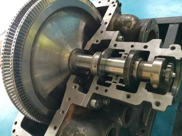
Extraction and regenerative turbines are steam turbines designed to extract steam at intermediate stages for use in industrial processes or for improving the overall efficiency of power plants. The extraction turbine allows steam to be taken out of the turbine at various pressure levels, providing steam for industrial heating or other processes. The regenerative turbine, on the other hand, focuses on increasing efficiency by using extracted steam to preheat the feedwater before it enters the boiler.
Both types of turbines are integral to combined heat and power (CHP) systems and various industrial processes where both electrical power and steam are required. These turbines ensure that steam is efficiently utilized in both power generation and industrial operations, minimizing waste and maximizing energy efficiency.
Importance in Industrial Applications
Extraction and regenerative turbines are widely used in industries like chemical manufacturing, refineries, pulp and paper, and district heating systems. Their ability to meet varying power and steam demands makes them essential for facilities that require process steam and electricity simultaneously. They provide significant economic and environmental advantages by improving fuel efficiency and reducing emissions.
Historical Development and Evolution
The use of steam turbines dates back to the 19th century, with significant innovations by pioneers like Sir Charles Parsons and Gustaf de Laval. The concept of steam extraction for industrial use emerged as industries sought ways to maximize the utilization of steam for both power generation and heating. Over time, the development of regenerative heating in turbines further improved efficiency by reducing the heat required to generate steam, thus conserving fuel and enhancing overall system performance.
Basic Function and Operation
Extraction turbines work by tapping steam at various stages of the expansion process, allowing it to be diverted for industrial or heating processes. The steam is extracted at controlled pressure levels, leaving the remaining steam to continue expanding through the turbine and generating power. Regenerative turbines, on the other hand, use some of the extracted steam to heat the feedwater, reducing the amount of fuel required to generate new steam, thus improving the thermal efficiency of the entire system.
Working Principles of Extraction and Regenerative Turbines
Thermodynamics of Extraction Turbines
Extraction turbines operate based on the Rankine cycle, where steam is generated in a boiler, expanded through the turbine to produce mechanical work, and then condensed back into water. In an extraction turbine, steam is extracted at one or more intermediate points before the final low-pressure stage. This steam can be used for industrial processes, heating, or other applications that require medium or low-pressure steam.
- Heat Addition: Steam is generated in a boiler from feedwater.
- Expansion in the Turbine: High-pressure steam is expanded through the turbine, producing mechanical energy. Steam is extracted at intermediate pressure points for external use.
- Condensation: The remaining steam continues to the low-pressure turbine stage, where it is condensed and returned to the cycle.
The Role of the Rankine Cycle
Both extraction and regenerative turbines operate within the framework of the Rankine cycle. In a regenerative turbine, part of the steam extracted from intermediate stages is used to preheat the feedwater entering the boiler. This process reduces the heat energy required to convert water into steam, improving the overall thermal efficiency of the cycle by recovering waste heat.
Energy Extraction through Multiple Pressure Levels
One of the key features of extraction turbines is their ability to supply steam at different pressure levels. This flexibility is crucial for industries that require steam at various temperatures and pressures for processes such as chemical reactions, drying, or heating. The ability to extract steam at multiple points makes these turbines highly adaptable to different industrial applications.
Regenerative Turbines: Enhancing Efficiency with Feedwater Heating
In regenerative turbines, the extraction of steam is used specifically to preheat the feedwater before it enters the boiler. By raising the temperature of the feedwater, less heat is required to produce steam, which significantly improves the overall efficiency of the power generation process. Regenerative feedwater heating is commonly used in large power plants to enhance efficiency and reduce fuel consumption.
Comparison with Other Types of Steam Turbines
Extraction and regenerative turbines offer unique benefits compared to traditional condensing or non-condensing turbines. While condensing turbines focus on maximizing power output by exhausting steam at very low pressures, extraction turbines prioritize flexibility by allowing steam to be diverted for industrial use. Similarly, regenerative turbines are designed to enhance efficiency by reducing fuel consumption, making them ideal for power plants focused on optimizing energy use.
Design and Key Components of Extraction and Regenerative Turbines
Turbine Structure: Rotor, Blades, Nozzles, and Seals
The core components of extraction and regenerative turbines are similar to those found in conventional steam turbines. These include the rotor, blades, nozzles, and seals, each of which plays a critical role in the turbine’s ability to convert steam energy into mechanical work.
- Rotor: The rotor is the central rotating shaft, which converts the energy from steam into mechanical motion. It is designed to withstand high rotational speeds and the stresses caused by expanding steam.
- Blades: Turbine blades are designed to extract energy from the steam as it expands through the turbine. The blades are carefully engineered to handle high pressures and temperatures while minimizing energy losses due to turbulence.
- Nozzles: Nozzles direct high-pressure steam onto the turbine blades, maximizing energy transfer. In extraction turbines, nozzles also control the flow of steam that is extracted at intermediate stages.
- Seals: Seals prevent steam leakage from the turbine, ensuring that the system operates efficiently.
Extraction Points: Steam Control and Flow Management
In extraction turbines, extraction points are located at various stages of the turbine, allowing steam to be diverted for industrial processes. These points are equipped with valves and control systems to regulate the flow and pressure of the extracted steam, ensuring that the right amount of steam is delivered at the required pressure for downstream processes.
Feedwater Heaters in Regenerative Turbines
Regenerative turbines include feedwater heaters that use extracted steam to preheat the water before it enters the boiler. These heaters are designed to recover waste heat from the turbine, improving the overall efficiency of the steam cycle. Feedwater heaters can be open or closed, depending on the specific design of the power plant.
- Open Feedwater Heaters: Steam and feedwater are mixed directly, allowing the steam to condense and transfer its heat to the water.
- Closed Feedwater Heaters: Steam transfers its heat to the feedwater through heat exchangers, without direct contact.
Material Selection for High-Temperature, High-Pressure Operation
Materials used in extraction and regenerative turbines must withstand high pressures and temperatures, as well as the mechanical stresses caused by steam expansion. Common materials include nickel-based alloys for turbine blades and rotors, which provide excellent resistance to heat and corrosion. Stainless steel and other high-strength alloys are also used to ensure long-term durability and reliability.
Blade Design and Aerodynamics
The design of turbine blades is crucial for maximizing efficiency and minimizing mechanical stress. Engineers use computational fluid dynamics (CFD) to optimize blade shape and aerodynamic profiles, ensuring that the steam flows smoothly over the blades and transfers as much energy as possible. Modern turbine blades are also designed to resist erosion from wet steam, which can cause wear over time.
Steam Properties and Their Role in Performance
The performance of extraction turbines is significantly influenced by the properties of the steam used in the system. Superheated steam, which is steam that has been heated beyond its boiling point, is generally preferred because it contains more energy and reduces the risk of condensation within the turbine. However, saturated steam—which contains both liquid and vapor phases—is also used in some applications, particularly when the extracted steam is required for heating processes that do not require superheated steam.
Steam Pressure, Temperature, and Quality Considerations
The pressure and temperature of the steam entering the turbine have a direct impact on the turbine’s performance and efficiency. High-pressure, high-temperature steam allows for greater energy extraction, as the steam carries more thermal energy that can be converted into mechanical work. The quality of the steam, which refers to the ratio of vapor to liquid, must also be carefully managed to avoid the formation of moisture, which can cause blade erosion and reduce efficiency.
Impact of Moisture Content on Efficiency and Blade Durability
As steam expands through the turbine, its pressure and temperature decrease, which can lead to condensation and the formation of wet steam. Wet steam contains water droplets that can erode the turbine blades, reducing the turbine’s efficiency and leading to maintenance issues. Managing moisture content is crucial in both extraction and regenerative turbines, as excessive moisture can reduce both performance and equipment lifespan.
The Role of Steam Extraction in Managing Steam Quality and Performance
In extraction turbines, steam is often extracted before it reaches the point where it starts to condense, ensuring that the steam remains dry and efficient for industrial processes. By controlling the pressure and temperature of the extracted steam, turbine operators can maintain high efficiency and prevent moisture-related issues in downstream applications.
Industrial Applications of Extraction and Regenerative Turbines
One of the most important applications of extraction and regenerative turbines is in power plants and CHP systems. In these systems, the turbines are used to generate electricity while simultaneously providing steam for industrial heating or other processes. This dual use of steam improves the overall efficiency of the power plant and reduces fuel consumption.
- CHP Systems: Combined heat and power systems use extraction turbines to provide both electricity and process steam. The extracted steam is used for heating, drying, or other industrial applications, while the turbine continues to generate electricity from the remaining steam.
- Power Plants: In large power plants, extraction turbines allow operators to balance power generation with steam extraction, ensuring that the plant operates at maximum efficiency.
Use in Petrochemical Refineries, Chemical Plants, and Manufacturing
Extraction turbines are widely used in petrochemical refineries, chemical plants, and manufacturing facilities where both electricity and steam are needed for industrial processes. These industries require steam at various pressures and temperatures for heating, chemical reactions, and other applications, making extraction turbines an ideal solution for meeting these demands.
- Petrochemical Refineries: In petrochemical refineries, steam is used to drive compressors, pumps, and other equipment. The extracted steam from the turbine is often used for heating or chemical processes within the refinery.
- Chemical Plants: Chemical plants use extraction turbines to provide process steam for chemical reactions and other manufacturing processes, while also generating electricity for on-site use.
- Manufacturing: In manufacturing plants, extraction turbines provide steam for drying, heating, and other processes that require medium or low-pressure steam.
Pulp and Paper Industry: Extraction and Heating Requirements
In the pulp and paper industry, steam is required for both drying paper and generating electricity. Extraction turbines allow mills to produce power while also supplying steam for drying processes, improving overall energy efficiency.
District Heating and Cooling Systems
In district heating and cooling systems, extraction turbines provide steam for heating or cooling buildings in cities and industrial complexes. The steam is extracted at intermediate pressure levels and distributed through a network of pipes to provide heating or cooling, improving the overall efficiency of the system.
Integration with Renewable Energy Sources (Biomass, Geothermal)
Extraction and regenerative turbines are increasingly being integrated into renewable energy systems, particularly in biomass and geothermal power plants. In biomass plants, organic materials such as wood chips, agricultural waste, or dedicated energy crops are burned to produce steam, which is expanded through an extraction turbine to generate electricity. The extracted steam is then used for heating or other industrial processes, improving overall efficiency.
In geothermal plants, steam is produced by tapping into geothermal reservoirs beneath the Earth’s surface. The steam is expanded through a turbine to generate electricity, and the extracted steam is used for district heating or industrial applications.
Advantages of Extraction and Regenerative Turbines
Flexibility in Power and Steam Generation
Extraction and regenerative turbines offer unparalleled flexibility in power and steam generation. They can be used to provide both electricity and process steam at various pressures and temperatures, making them ideal for industries that require both power and heat. This flexibility allows operators to adjust the system based on the specific energy demands of the facility, improving overall efficiency.
Improved Efficiency through Steam Extraction
By extracting steam at intermediate stages, extraction turbines improve the overall efficiency of the steam cycle. The extracted steam is used for industrial processes or heating, reducing the amount of fuel required to produce additional steam. This improves the overall thermal efficiency of the system and reduces fuel consumption.
Economic Benefits in Industrial Cogeneration
In cogeneration systems, extraction turbines provide significant economic benefits by reducing energy costs. By generating both electricity and process steam from the same steam source, industries can reduce their reliance on external energy sources, lowering fuel costs and improving operational efficiency.
Environmental Impact Reduction
The improved efficiency of extraction and regenerative turbines also leads to reduced environmental impact. By reducing fuel consumption, these turbines help lower carbon dioxide (CO₂) emissions and other pollutants, supporting industries in their efforts to meet environmental regulations and reduce their carbon footprint.
Enhanced Heat Recovery and Energy Conservation in Regenerative Turbines
Regenerative turbines offer additional benefits by improving heat recovery and energy conservation. By using extracted steam to preheat the feedwater, regenerative turbines reduce the amount of fuel required to generate steam, improving the overall thermal efficiency of the power plant. This reduces both fuel consumption and emissions, making regenerative turbines an essential part of energy-efficient power generation.
Challenges and Limitations
Complexity of Steam Flow and Control Systems
One of the main challenges associated with extraction and regenerative turbines is the complexity of steam flow and control systems. Extracting steam at various pressure levels requires careful control to ensure that the right amount of steam is delivered to downstream processes without compromising the efficiency of the turbine. Balancing steam extraction and power generation requires sophisticated control systems and monitoring tools.
Balancing Power Output and Steam Extraction
In extraction turbines, balancing power output and steam extraction can be challenging. If too much steam is extracted, the turbine may not generate enough electricity to meet the plant’s needs. Conversely, if not enough steam is extracted, the industrial processes may not receive the required amount of steam. Achieving the right balance between power and steam generation requires careful planning and system design.
Risk of Erosion from Wet Steam and Moisture
The formation of wet steam in extraction turbines can lead to blade erosion, reducing the efficiency of the turbine and leading to costly maintenance. Managing moisture content in the steam and ensuring that the turbine operates within its design limits can help reduce the risk of erosion and extend the lifespan of the turbine.
Maintenance and Reliability Issues in High-Pressure Systems
Extraction and regenerative turbines operate at high pressures and temperatures, which can lead to mechanical wear and tear over time. Regular maintenance is required to ensure that the turbine operates efficiently and reliably. In high-pressure systems, maintenance challenges can be more pronounced, as the equipment is subject to higher mechanical stresses.
Efficiency Losses in Non-ideal Operating Conditions
The efficiency of extraction and regenerative turbines can be affected by non-ideal operating conditions, such as fluctuations in steam pressure, temperature, or demand. Ensuring that the turbine operates under optimal conditions requires sophisticated control systems and real-time monitoring, which can be challenging to implement and maintain.
Performance Optimization and Efficiency Improvements
Digitalization and Real-time Monitoring
Advances in digitalization and real-time monitoring are transforming the way extraction and regenerative turbines are operated and maintained. Modern turbines are equipped with sensors that provide real-time data on temperature, pressure, vibration, and steam quality. This data can be used to optimize turbine performance, identify potential issues before they lead to equipment failure, and improve overall efficiency.
AI-driven Predictive Maintenance and System Optimization
Artificial intelligence (AI) is increasingly being used to analyze data from turbines and recommend maintenance actions. Predictive maintenance systems use data from sensors to predict when components are likely to fail, allowing operators to perform maintenance before a breakdown occurs. This reduces downtime and improves the reliability of extraction and regenerative turbines.
Advanced Blade Materials and Coatings
The development of new blade materials and coatings is helping to improve the efficiency and durability of extraction and regenerative turbines. Advanced materials, such as nickel-based superalloys and ceramic coatings, allow turbines to operate at higher temperatures and pressures without suffering from corrosion or erosion. These materials improve the efficiency of the turbine and reduce the need for frequent maintenance.
Retrofitting Older Turbines for Efficiency Gains
Many older extraction and regenerative turbines can be retrofitted with modern technology to improve their efficiency and performance. Retrofitting options include upgrading turbine blades to more aerodynamic designs, installing advanced control systems, and integrating digital monitoring tools. These retrofits can extend the lifespan of older turbines and improve their efficiency, reducing the need for new equipment and lowering operating costs.
Techniques for Improving Feedwater Heating Efficiency in Regenerative Turbines
In regenerative turbines, the efficiency of feedwater heating can be improved by optimizing the design of feedwater heaters and heat exchangers. Modern regenerative systems use advanced designs that maximize heat transfer while minimizing pressure losses, improving the overall efficiency of the steam cycle.
Future Trends and Innovations in Extraction and Regenerative Turbines
Integration with Smart Grids and Hybrid Power Systems
The future of extraction and regenerative turbines will involve greater integration with smart grids and hybrid power systems. By connecting turbines to smart grids, operators can optimize energy production based on real-time demand, improving efficiency and reducing energy waste. Hybrid power systems that combine extraction turbines with battery storage or renewable energy sources will allow for more flexible and efficient energy management.
Digital Twins for Predictive Analytics and Turbine Management
The use of digital twins—virtual models of physical systems—is revolutionizing turbine operation and maintenance. By creating a digital twin of an extraction or regenerative turbine, operators can simulate different operating conditions and optimize turbine performance without disrupting real-world operations. Predictive analytics tools use data from the digital twin to identify potential performance issues and recommend adjustments, improving turbine efficiency and reliability.
Role in Carbon Capture and Storage (CCS) Systems
Extraction and regenerative turbines will play a key role in carbon capture and storage (CCS) systems, which aim to reduce carbon emissions from fossil-fuel power plants. CCS technology captures carbon dioxide (CO₂) emissions from power plants and industrial facilities and stores them underground, preventing them from entering the atmosphere. Extraction turbines, with their ability to provide steam for CCS processes, will be an integral part of this technology.
Advances in Blade Design, Materials, and 3D Printing
The development of new blade designs and materials is helping to improve the efficiency and performance of extraction and regenerative turbines. 3D printing technology is being used to create complex, high-precision parts that were previously difficult or impossible to manufacture using traditional methods. This allows for the optimization of blade designs, leading to higher efficiency and reduced manufacturing costs.
Sustainable Energy Solutions: Biomass, Geothermal, and Solar Integration
Extraction and regenerative turbines are increasingly being integrated into sustainable energy solutions, such as biomass, geothermal, and solar power plants. By using steam generated from renewable sources, these turbines help reduce reliance on fossil fuels and support the transition to cleaner energy. In addition, extraction turbines are being used in conjunction with solar thermal systems to generate electricity and provide heating, improving the overall efficiency of solar power plants.
Conclusion
Extraction and regenerative turbines remain a vital part of many industries, providing efficient solutions for facilities that require both electricity and process steam. Their role in cogeneration systems, district heating, and industrial processes makes them indispensable in sectors that aim to optimize energy use and reduce operational costs. As industries continue to evolve, extraction and regenerative turbines will play a key role in the transition toward more sustainable and efficient energy systems, particularly in renewable energy applications and hybrid power systems.
With ongoing advancements in turbine design, digitalization, and materials science, extraction and regenerative turbines are poised to become even more efficient and reliable. Their flexibility, cost-effectiveness, and ability to integrate with future energy technologies ensure that they will remain relevant in the future of global energy systems.
To write a comprehensive 10,000-word document on Impulse vs. Reaction Turbines, this content will cover their definitions, working principles, design differences, applications, performance, advantages, challenges, and future trends. This detailed outline provides a logical and structured approach to understanding the two types of turbines, highlighting how they are similar, how they differ, and where each is best used.
Impulse vs. Reaction Turbines
Steam turbines are devices that convert the thermal energy in steam into mechanical work, which can then be used to generate electricity or drive mechanical equipment. They are integral components in power plants, industrial facilities, and marine propulsion systems. The two primary types of steam turbines are impulse turbines and reaction turbines, each with distinct characteristics and applications.
Significance of Impulse and Reaction Turbines in Industry
Both impulse and reaction turbines play crucial roles in energy generation and mechanical power applications worldwide. Understanding their differences is key to optimizing efficiency, performance, and cost-effectiveness in various industrial settings. While impulse turbines are often used where high-pressure, low-flow steam is required, reaction turbines are better suited to scenarios where low-pressure, high-flow steam is advantageous.
Purpose of the Comparison
This document aims to provide a detailed comparison between impulse and reaction turbines, exploring their principles, designs, and applications. By examining the strengths and weaknesses of each type, readers will gain a comprehensive understanding of which turbine is best suited for specific uses and why.
Basic Definitions
- Impulse Turbines: These turbines convert kinetic energy from high-velocity steam jets into mechanical energy. The steam passes through nozzles that accelerate it, and the resulting high-speed jets hit the turbine blades, causing the rotor to spin.
- Reaction Turbines: In these turbines, steam expands continuously as it passes over the blades, generating thrust that drives the rotor. The blades themselves act as nozzles, allowing for smooth and continuous energy conversion.
Steam turbines are mechanical devices that convert the thermal energy in steam into mechanical energy, which is then used to drive generators for electricity production or power industrial machinery. Steam turbines have been a cornerstone of industrial power generation since the late 19th century and continue to play a crucial role in various applications today, from large power plants to marine propulsion systems.
These machines operate on the principle of the Rankine cycle, where water is heated, converted into steam, expanded through a turbine to produce work, and then condensed back to water to complete the cycle. By effectively harnessing the energy of high-pressure steam, steam turbines have enabled significant advancements in electricity generation and mechanical power.
Steam turbines are categorized based on how they extract energy from steam, and two of the most prominent types are impulse turbines and reaction turbines. Understanding the differences between these two types is essential for selecting the right equipment for a given application, as each has its own unique advantages, operational characteristics, and optimal usage scenarios.
Importance of Impulse and Reaction Turbines in Power Generation
Both impulse and reaction turbines are essential for efficient power generation and mechanical power applications around the world. These turbines are used in thermal power plants, nuclear power stations, geothermal plants, industrial plants, and marine vessels, among other settings. Their ability to convert the energy of steam into mechanical work with high efficiency makes them indispensable in industries where reliable and efficient energy conversion is a priority.
Impulse turbines and reaction turbines are designed to handle different types of steam conditions and flow rates. While impulse turbines are known for their ability to handle high-pressure, low-flow steam conditions, reaction turbines excel in environments where low-pressure, high-flow steam is available. Each turbine type has its own set of characteristics, which makes it more suitable for certain applications. For example:
- Impulse turbines are often used in situations where steam enters at high pressure and needs to be expanded quickly to produce mechanical energy. They are typically found in smaller, high-pressure steam systems, such as in certain sections of thermal power plants and marine engines.
- Reaction turbines, on the other hand, are better suited for applications where steam flow is continuous, and gradual energy extraction is desired. They are commonly used in large-scale power plants and situations where low-pressure, high-flow steam must be efficiently utilized.
Understanding when to use impulse versus reaction turbines can significantly impact the efficiency, cost, and reliability of a power generation system. This makes the comparison between the two turbine types crucial for engineers, operators, and decision-makers.
Purpose of the Comparison
The primary purpose of this comparison is to provide a detailed analysis of impulse turbines and reaction turbines, focusing on their design, working principles, applications, efficiency, and performance. By examining the strengths, weaknesses, and unique characteristics of each type, this document aims to guide readers in understanding which turbine type is best suited for specific industrial and power generation scenarios.
This analysis will explore various factors, including:
- Mechanics and Thermodynamics: How each turbine type converts steam energy into mechanical energy.
- Design Considerations: Differences in blade structure, nozzle arrangement, and stage configuration.
- Efficiency Metrics: Performance of each turbine under varying operating conditions.
- Applications: Real-world examples of where each turbine type is most effectively used.
- Cost and Maintenance: Operational costs, maintenance requirements, and reliability issues.
- Technological Developments: Recent advances and future trends in turbine design and operation.
By the end of this document, readers will have a comprehensive understanding of impulse and reaction turbines, which will help them make informed decisions about turbine selection and operation in various industrial contexts.
Basic Definitions and Concepts
To begin, it’s essential to understand the basic definitions of impulse and reaction turbines, as well as the concepts that differentiate them:
- Impulse Turbines:
- In impulse turbines, steam is directed through nozzles that convert its pressure energy into high-velocity jets. These jets strike the blades of the turbine, causing the rotor to spin. The key characteristic of an impulse turbine is that the pressure drop (and therefore energy conversion) occurs entirely in the nozzles, and not on the blades. This means that the blades themselves only absorb kinetic energy, and there is no pressure change as steam flows over them.
- Reaction Turbines:
- Reaction turbines work on a different principle where steam undergoes continuous expansion as it passes over the blades. Here, the blades are shaped to act as nozzles themselves, allowing steam to expand and accelerate while flowing through the turbine. This causes a pressure drop across both the stator (fixed blades) and the rotor (moving blades), with energy being extracted from both. The main characteristic of reaction turbines is that both pressure and velocity changes occur as steam passes through the turbine blades, leading to a more gradual and continuous energy conversion process.
- Key Differences:
- Impulse turbines rely on discrete high-velocity steam jets for energy conversion, and the energy transfer happens primarily due to the impact of these jets on the turbine blades.
- Reaction turbines operate on the principle of a continuous pressure drop and expansion of steam across the turbine, with energy extracted from the reaction forces generated by this process.
Understanding these fundamental differences is crucial to appreciating why each turbine design is used in specific scenarios and how they can be optimized for maximum efficiency. The sections that follow will delve deeper into the working principles, design features, and applications of both impulse and reaction turbines, providing a thorough comparison that highlights their unique characteristics.
History and Evolution of Impulse and Reaction Turbines
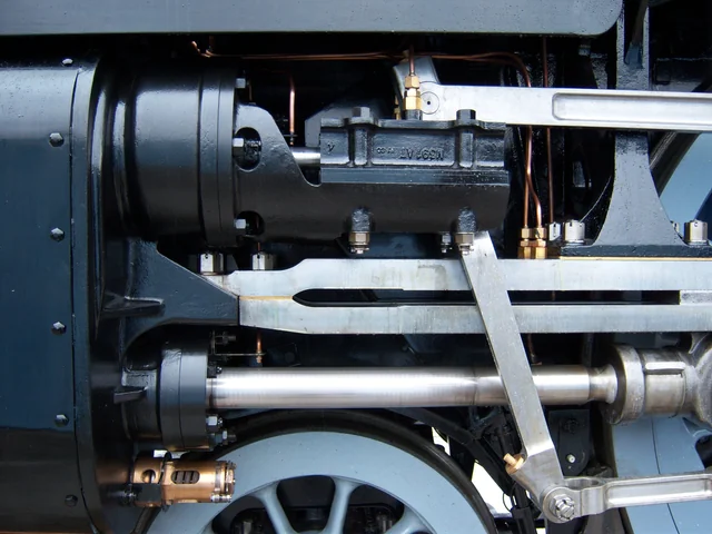
The evolution of steam turbines began in the late 19th century as industries sought more efficient ways to convert heat energy into mechanical work. Before steam turbines, steam engines were the predominant method of harnessing steam power. However, they were relatively inefficient, bulky, and required significant maintenance. The development of steam turbines marked a turning point in the field of mechanical engineering, leading to significant advancements in efficiency and reliability.
The basic concept of using steam to generate mechanical energy dates back to ancient times, with early designs such as the Aeolipile, invented by Hero of Alexandria in the 1st century AD. This device used steam to create rotary motion, but it was more of a novelty than a practical engine. It wasn’t until the Industrial Revolution that steam power became integral to industries, primarily through the use of steam engines. However, it was the innovation of steam turbines that truly revolutionized power generation.
Inventions by Charles Parsons, Gustaf de Laval, and Others
The modern steam turbine emerged in the late 1800s, thanks to the pioneering work of inventors like Sir Charles Parsons and Gustaf de Laval, who laid the foundations for the impulse and reaction turbine designs, respectively.
- Gustaf de Laval and the Impulse Turbine:
- In 1883, Swedish engineer Gustaf de Laval developed one of the first impulse turbines, which was initially used for driving cream separators. De Laval’s design utilized high-velocity steam jets directed onto a set of blades attached to a rotating disc. The key innovation was the use of nozzles to accelerate steam to high speeds, converting its thermal energy into kinetic energy before it impacted the turbine blades.
- This design was simple, effective, and could operate at extremely high speeds, making it suitable for small-scale applications. De Laval’s impulse turbine could reach speeds of up to 30,000 RPM, which was unprecedented at the time. It demonstrated that steam turbines could be more efficient and reliable than traditional steam engines.
- Sir Charles Parsons and the Reaction Turbine:
- Sir Charles Parsons, a British engineer, is credited with inventing the first practical reaction turbine in 1884. Parsons’ design was revolutionary because it allowed for a gradual expansion of steam across multiple stages, leading to continuous energy extraction. Unlike de Laval’s impulse turbine, which relied on high-velocity steam jets, Parsons’ reaction turbine used a combination of stationary and moving blades that allowed steam to expand and transfer energy continuously.
- Parsons’ turbine was initially used to drive electrical generators, and it marked the beginning of the widespread use of turbines for electricity generation. His turbine was capable of operating at much lower speeds than de Laval’s, but it was far more efficient in converting steam energy into mechanical work, especially for larger applications. Parsons’ design became the standard for power generation in thermal plants, and its principles are still used in modern turbines.
- Further Innovations and Hybrid Designs:
- Following the pioneering work of de Laval and Parsons, numerous engineers and inventors contributed to the advancement of steam turbine technology. The early 20th century saw the development of multi-stage turbines, which combined the principles of impulse and reaction designs. These hybrid turbines utilized impulse stages at the high-pressure end, where steam enters at high velocity, and reaction stages at the low-pressure end, where continuous expansion was more efficient.
- These innovations allowed turbines to operate across a wider range of pressures and temperatures, making them suitable for various industrial applications. The flexibility of combining impulse and reaction stages led to the development of highly efficient compound turbines, which became standard in power plants worldwide.
Evolution of Impulse and Reaction Turbines Over Time
The development of steam turbines has continued to evolve, driven by the need for greater efficiency, reliability, and adaptability. Both impulse and reaction turbines have undergone significant improvements since their inception, with advancements in materials, engineering design, and thermodynamics contributing to their performance.
- Advancements in Materials and Manufacturing:
- Early turbines were limited by the materials available, which often could not withstand high temperatures and pressures. Advances in metallurgy, particularly the development of alloy steels and later superalloys, enabled turbines to operate at much higher temperatures and pressures without succumbing to mechanical stress or thermal fatigue.
- The use of advanced manufacturing techniques, such as precision casting and additive manufacturing (3D printing), has further enhanced the design of turbine blades and rotors. These advancements have allowed for more complex and aerodynamically optimized blade shapes, which improve efficiency and reduce energy losses.
- Development of Multi-stage and Compounding Designs:
- The introduction of multi-stage turbines was a game-changer in steam turbine technology. In early single-stage impulse turbines, steam was expanded in one step, which often led to significant energy losses. Multi-stage turbines, by contrast, allowed for steam to be expanded gradually across multiple stages, with each stage extracting a portion of the energy. This approach greatly improved the overall efficiency of the turbine.
- Compound turbines that combine impulse and reaction stages are now common in many power plants. By leveraging the strengths of both designs, these turbines can handle varying pressure conditions and optimize energy extraction at different stages of the steam expansion process.
- Thermodynamic Efficiency Improvements:
- Over the years, engineers have developed ways to improve the thermodynamic efficiency of turbines. One such method is the reheat cycle, where steam is partially expanded in the turbine, reheated in a boiler, and then expanded further. This process reduces moisture content and increases the average temperature of the heat input, which improves efficiency.
- Regenerative feedwater heating is another technique used to enhance efficiency. In this process, steam is extracted from the turbine at various stages and used to preheat the feedwater before it enters the boiler. This reduces the energy required to convert water into steam, leading to better overall cycle efficiency. Both impulse and reaction turbines can be integrated with these thermodynamic improvements.
Technological Milestones and Improvements
The continued evolution of impulse and reaction turbines has been marked by several key technological milestones, which have expanded their applications and enhanced their performance:
- Blade Cooling Technologies:
- In high-temperature applications, turbine blades can be subject to extreme thermal stress. To address this, engineers developed blade cooling technologies that allow turbines to operate at higher temperatures without damaging the blades. Impulse and reaction turbines have benefited from these innovations, enabling them to operate more efficiently in high-temperature environments like gas-fired and nuclear power plants.
- Computational Fluid Dynamics (CFD) and Blade Design:
- The use of computational fluid dynamics (CFD) has revolutionized the design of turbine blades. CFD allows engineers to simulate the flow of steam through the turbine and optimize the shape of the blades for maximum efficiency. This has led to the development of more aerodynamic blades that minimize energy losses due to turbulence and improve the overall performance of both impulse and reaction turbines.
- Digitalization and Smart Monitoring:
- Modern turbines are equipped with smart monitoring systems that collect real-time data on temperature, pressure, and mechanical performance. This data is used to optimize turbine operation, predict maintenance needs, and prevent failures. The integration of digital technology has made turbines more reliable and easier to maintain, reducing downtime and extending the lifespan of equipment.
- Predictive maintenance and digital twins are examples of how digital technology is being applied to improve turbine performance. Digital twins are virtual models of physical turbines that allow operators to test different operating conditions and optimize performance without disrupting actual operations.
- Integration with Renewable Energy Sources:
- Impulse and reaction turbines have found new applications in renewable energy systems, such as biomass, geothermal, and solar thermal power plants. These turbines can be adapted to utilize steam generated from renewable sources, helping to reduce carbon emissions and support the transition to cleaner energy.
- The adaptability of impulse and reaction designs has made them essential components in hybrid energy systems, where they can work alongside other technologies, such as gas turbines and wind power, to provide stable and reliable energy output.
Conclusion of Historical Evolution
The history of impulse and reaction turbines is a testament to the ingenuity and innovation of engineers who sought to harness the power of steam in the most efficient way possible. From the early designs of de Laval and Parsons to the sophisticated multi-stage, digitally optimized turbines of today, the development of these machines has been driven by the need for higher efficiency, reliability, and adaptability.
Today, impulse and reaction turbines continue to be refined and improved, ensuring they remain essential tools in power generation and industrial processes around the world. Understanding their historical evolution helps engineers appreciate the technological advancements that make modern turbines so effective and highlights the potential for future innovations in turbine technology.
Working Principles of Impulse Turbines
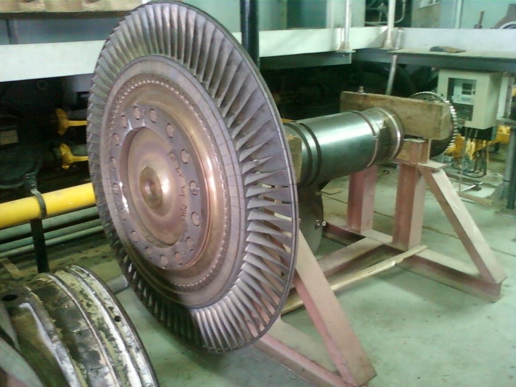
Impulse turbines operate based on the principle of impulse, where high-pressure steam is converted into high-velocity jets, which then strike the turbine blades, causing the rotor to spin. The core idea behind impulse turbines is that the energy transfer happens solely through the kinetic energy of the steam jets, rather than through a pressure difference across the turbine blades.
- The Role of Nozzles:
- In an impulse turbine, steam from the boiler is directed into a set of nozzles. The purpose of these nozzles is to convert the pressure energy of the steam into kinetic energy by accelerating the steam to a high velocity. The nozzles are designed to create a focused jet of steam that moves at a very high speed.
- The design of the nozzles is crucial because it determines how efficiently the turbine can convert steam energy into mechanical work. The nozzles are typically shaped to expand the steam as it exits, causing the pressure to drop and the velocity to increase. This process is known as isentropic expansion, meaning that the steam expands without any heat exchange, ensuring that the conversion from pressure to kinetic energy is efficient.
- High-Velocity Steam Jets and Blade Interaction:
- Once the steam exits the nozzles, it is directed toward the turbine blades. These blades are mounted on a rotating disc, known as the rotor, and are positioned in a way that they intercept the high-velocity steam jets. As the steam hits the blades, it transfers its kinetic energy to them, causing the rotor to spin.
- The blades of an impulse turbine are typically bucket-shaped or cup-shaped to efficiently capture the energy of the steam jets. The design ensures that the steam is redirected as it leaves the blades, which helps in maintaining the momentum and minimizing energy loss. The force exerted by the steam on the blades is what drives the turbine, converting the kinetic energy of the steam into rotational mechanical energy.
- No Pressure Change Across the Blades:
- A defining characteristic of impulse turbines is that the pressure drop occurs only in the nozzles, not across the blades. This means that by the time the steam reaches the blades, it is already at a lower pressure but a much higher velocity. The blades are designed only to capture and redirect this high-velocity steam without causing any further pressure drop.
- This aspect makes impulse turbines suitable for situations where steam enters at very high pressure and needs to be expanded quickly. Since there is no pressure change across the blades, the turbine can operate efficiently without needing a complex blade design to manage pressure variations.
Energy Conversion: Kinetic to Mechanical Energy
Impulse turbines convert the kinetic energy of steam into mechanical energy through the following process:
- Steam Acceleration and Expansion:
- The high-pressure steam from the boiler is first expanded through the nozzles, which causes a drop in pressure and an increase in velocity. The nozzles effectively convert the enthalpy (heat content) of the steam into kinetic energy, producing a jet of steam that is much faster and has a lower pressure than the original steam.
- The velocity of the steam can be exceptionally high, often reaching speeds of up to 1,200 meters per second (m/s) or more. This rapid acceleration is what allows the turbine to extract a significant amount of energy from the steam.
- Impulse Force on Blades:
- As the high-velocity steam strikes the turbine blades, it imparts an impulse force to them. The design of the blades ensures that the steam is redirected efficiently, allowing for maximum energy transfer. The steam jets exert a force on the blades due to the change in momentum, and this force causes the rotor to spin.
- The force exerted by the steam on the blades can be described using Newton’s Second Law of motion, which states that the force is equal to the rate of change of momentum. In the case of impulse turbines, the change in direction and speed of the steam as it strikes the blades results in a significant transfer of energy to the rotor.
- Conversion to Mechanical Work:
- The spinning rotor can be connected to a generator or any mechanical device that needs to be powered. As the rotor turns, it converts the kinetic energy of the steam into mechanical work, which can then be used to generate electricity, drive compressors, or power pumps, depending on the application.
- Impulse turbines are particularly efficient at handling high-speed, high-pressure steam, making them ideal for power generation in situations where steam can be expanded rapidly to create high-velocity jets.
Thermodynamics and the Rankine Cycle in Impulse Turbines
Impulse turbines are an integral part of the Rankine cycle, which is a thermodynamic cycle used to describe the conversion of heat energy into mechanical work. The Rankine cycle consists of four main processes:
- Isobaric Heat Addition (Boiler):
- In the boiler, water is heated under constant pressure until it becomes superheated steam. This steam is stored at high pressure and temperature, ready to be expanded through the turbine.
- Isentropic Expansion (Turbine):
- The high-pressure steam enters the nozzles of the impulse turbine, where it expands isentropically (without heat exchange), converting pressure energy into kinetic energy. The steam then strikes the blades, transferring its kinetic energy to the rotor and causing it to spin.
- During this process, the steam’s pressure drops significantly, and most of its energy is converted into mechanical work. Because impulse turbines only involve a pressure drop in the nozzles, they allow for efficient conversion of steam energy into rotational motion.
- Isobaric Heat Rejection (Condenser):
- After passing through the turbine, the steam is directed into a condenser, where it cools down and condenses back into water. This process is necessary to maintain the flow of steam through the system and to recycle the water for continuous use.
- Isentropic Compression (Pump):
- The condensed water is pumped back into the boiler at high pressure, completing the cycle. The pump raises the pressure of the water without significantly increasing its temperature, preparing it to be reheated and converted back into steam.
Impulse turbines play a critical role in the isentropic expansion part of the Rankine cycle, where they convert the steam’s thermal and pressure energy into mechanical energy. Their design ensures that the process is efficient, with minimal energy losses during the conversion.
Multi-stage Impulse Turbines: Compounding and Efficiency
To improve efficiency and allow for better control of steam expansion, many modern impulse turbines are designed with multiple stages, known as compounding. This approach involves dividing the steam expansion process into several smaller steps, with each step extracting a portion of the energy from the steam.
- Why Compounding is Necessary:
- In a single-stage impulse turbine, expanding all the steam in one go would result in extremely high steam velocities, which can lead to mechanical inefficiencies and excessive wear on the turbine blades. It would also mean a significant loss of energy as the steam exits the turbine at a high velocity, leading to wasted kinetic energy.
- Compounding addresses this issue by dividing the steam expansion into multiple stages, where each stage consists of a nozzle and a set of blades. This gradual reduction in steam pressure and velocity across several stages allows for more efficient energy extraction and reduces wear on the turbine components.
- Types of Compounding:
- Velocity Compounding: In this design, high-velocity steam from the nozzles is directed through multiple rows of moving and stationary blades. The moving blades absorb energy from the steam, while the stationary blades redirect the flow to ensure it hits the next row of moving blades effectively. This helps to manage extremely high steam velocities and makes the turbine more efficient.
- Pressure Compounding: Pressure compounding divides the pressure drop into multiple stages, with each stage having its own set of nozzles and blades. This approach reduces the pressure gradually, ensuring that the steam does not expand too rapidly and allowing for smoother, more controlled energy extraction.
- Combination of Both: Modern impulse turbines often use a combination of both velocity and pressure compounding to achieve optimal performance. This design ensures that steam expansion is gradual and efficient, leading to improved energy conversion rates and lower mechanical wear.
- Efficiency Gains:
- Multi-stage impulse turbines are far more efficient than their single-stage counterparts, as they allow for greater control over the expansion process. By managing the steam pressure and velocity across multiple stages, these turbines can achieve higher isentropic efficiency, meaning they convert a greater percentage of the steam’s energy into useful mechanical work.
- Compounded turbines also help to reduce the exit velocity of the steam, minimizing energy losses as the steam leaves the turbine. This means more of the energy generated in the boiler is used for productive work, rather than being lost as waste heat.
Conclusion on Impulse Turbine Principles
Impulse turbines are highly efficient machines that convert the kinetic energy of high-velocity steam jets into mechanical work. By focusing on accelerating steam through nozzles and then using that kinetic energy to drive turbine blades, they effectively harness the power of steam without relying on pressure differences across the blades. This design makes them ideal for high-pressure applications where rapid energy conversion is needed.
The use of multi-stage designs and compounding has further enhanced the efficiency of impulse turbines, making them suitable for a wide range of applications, from power generation to mechanical drives. Understanding the working principles of impulse turbines helps engineers and operators optimize their performance, ensuring they are used effectively in various industrial and energy settings.
Working Principles of Reaction Turbines
Reaction turbines operate on a different principle compared to impulse turbines. While impulse turbines rely on high-velocity steam jets that impact the blades, reaction turbines utilize the reaction force generated by the expansion and acceleration of steam as it flows over the blades. In a reaction turbine, energy is extracted continuously as steam expands and passes through both fixed and moving blades, leading to a smooth and gradual conversion of thermal energy into mechanical energy.
- Continuous Expansion and Pressure Drop:
- Unlike impulse turbines, where steam undergoes a pressure drop only in the nozzles, reaction turbines have a continuous pressure drop across both the fixed and moving blades. The steam expands as it flows through the turbine, and this expansion creates a reaction force that drives the rotor.
- The key to the reaction turbine’s operation is that both the stationary (fixed) and rotating (moving) blades act as nozzles, allowing the steam to expand and accelerate. As the steam accelerates, it exerts a reactive force on the blades, pushing them and causing the rotor to spin.
- Role of Fixed and Moving Blades:
- In a reaction turbine, the steam first passes through a set of fixed blades (stator), which direct the steam onto the moving blades (rotor) at an appropriate angle. The fixed blades are designed to control the steam flow and ensure that it strikes the moving blades efficiently.
- As the steam flows over the moving blades, it undergoes further expansion and acceleration, generating a reaction force that drives the blades forward. This continuous process of expansion and acceleration allows the turbine to extract energy from the steam smoothly and efficiently.
- Reaction Force and Energy Conversion:
- The principle of operation in a reaction turbine is based on Newton’s Third Law of Motion, which states that for every action, there is an equal and opposite reaction. As steam flows through the blades and accelerates, it generates a reactive force that pushes against the blades, causing them to move.
- The continuous nature of this energy conversion process makes reaction turbines particularly suitable for situations where a steady and smooth power output is required. Because the steam expands across both the fixed and moving blades, energy extraction is more gradual and continuous compared to the discrete, high-impact energy transfer in impulse turbines.
Pressure and Velocity Dynamics in Reaction Blades
One of the defining characteristics of reaction turbines is the way they handle changes in steam pressure and velocity. The design of the blades ensures that these changes are managed efficiently, allowing the turbine to extract maximum energy from the steam.
- Pressure Drop Across Blades:
- In reaction turbines, the pressure drop occurs across both the stationary and rotating blades. As steam flows from one set of blades to the next, its pressure gradually decreases, and its velocity increases. This contrasts with impulse turbines, where the pressure drop occurs only in the nozzles, and the blades merely redirect high-velocity steam.
- The gradual pressure drop across multiple stages makes reaction turbines ideal for applications where the steam needs to be expanded over a longer period, allowing for continuous energy extraction. This design minimizes the abrupt changes in energy that can lead to inefficiencies and mechanical stress.
- Blade Design for Expansion and Acceleration:
- The blades of a reaction turbine are designed to allow steam to expand and accelerate as it flows over them. This is achieved by shaping the blades in a way that they act like nozzles, causing the steam to accelerate as it exits. This acceleration generates a reaction force that drives the blades and the rotor.
- The aerodynamic design of the blades is crucial for ensuring that the steam flow remains smooth and efficient, minimizing turbulence and energy losses. The blades are often curved or twisted to optimize the flow path of the steam, ensuring that it strikes the blades at the right angle and with maximum efficiency.
- Velocity and Energy Transfer:
- As the steam moves through the reaction turbine, its velocity increases while its pressure decreases. This continuous acceleration ensures that energy is transferred smoothly from the steam to the rotor, providing a steady and consistent power output.
- The energy transfer process in reaction turbines is highly efficient because it utilizes both the kinetic energy (from the steam’s velocity) and the pressure energy (from the continuous expansion) of the steam. This dual energy extraction mechanism is one of the reasons why reaction turbines can achieve high efficiencies in certain operating conditions.
Thermodynamics and the Rankine Cycle in Reaction Turbines
Reaction turbines are also integral to the Rankine cycle, the thermodynamic process that governs how steam is converted into mechanical work. However, the way they fit into the cycle is slightly different from impulse turbines due to their continuous pressure and energy changes.
- Isentropic Expansion in Reaction Stages:
- In the Rankine cycle, the steam expands isentropically (without heat loss) through the turbine, converting thermal energy into mechanical energy. In a reaction turbine, this expansion is continuous and occurs across multiple stages of fixed and moving blades.
- The design of the reaction turbine allows the steam to expand gradually, maintaining a more consistent flow of energy transfer. This gradual expansion helps to reduce moisture content in the steam, which is a critical factor in maintaining efficiency and preventing blade erosion.
- Pressure and Temperature Changes:
- The continuous expansion in reaction turbines means that the pressure and temperature of the steam decrease steadily as it passes through the turbine. This contrasts with the sharp pressure drop seen in impulse turbines. The steady reduction in pressure and temperature is beneficial for maintaining smooth and efficient energy conversion.
- The thermodynamic efficiency of a reaction turbine is often higher when operating under conditions where steam can be expanded over a wide range of pressures. This makes reaction turbines well-suited for large power plants, where the goal is to maximize energy extraction from steam.
- Integration with Regenerative and Reheat Cycles:
- Like impulse turbines, reaction turbines can be integrated with regenerative feedwater heating and reheat cycles to improve efficiency. In a regenerative cycle, steam is extracted from the turbine at various stages and used to preheat the feedwater, reducing the amount of energy needed to convert it into steam. This preheating process improves the overall efficiency of the system.
- Reheating is another technique used in conjunction with reaction turbines. After steam has partially expanded in the turbine, it is sent back to the boiler to be reheated and then expanded further. This reduces the formation of moisture in the later stages of the turbine, which can improve efficiency and extend the life of the turbine blades.
Stage Configuration: Single and Multi-stage Reaction Turbines
Reaction turbines can be configured as single-stage or multi-stage machines, depending on the requirements of the application. The choice between these configurations affects the efficiency, power output, and operational flexibility of the turbine.
- Single-stage Reaction Turbines:
- Single-stage reaction turbines are simpler and typically used in applications where the power demand is relatively low, and the steam conditions do not require extensive expansion. These turbines are easier to design and maintain, but they may not achieve the same level of efficiency as multi-stage configurations.
- They are often used in smaller industrial applications where the primary goal is to provide mechanical power for processes rather than generate large amounts of electricity.
- Multi-stage Reaction Turbines:
- Multi-stage reaction turbines are more complex and are designed to handle significant steam expansion over multiple stages. Each stage consists of a set of fixed and moving blades that gradually expand the steam, extracting energy at every point.
- The advantage of multi-stage designs is that they can handle larger volumes of steam and operate efficiently over a wide range of pressures. This makes them ideal for large-scale power plants and marine propulsion systems, where continuous, high-efficiency operation is essential.
- Multi-stage turbines can also be compound turbines, which combine elements of impulse and reaction designs to optimize performance. For example, the high-pressure stages might use impulse designs, while the low-pressure stages employ reaction principles to take advantage of continuous expansion.
- Efficiency Considerations:
- Multi-stage reaction turbines are generally more efficient than single-stage versions because they can extract more energy from the steam by expanding it gradually. However, this increased efficiency comes with a trade-off in terms of complexity and cost.
- The choice between single-stage and multi-stage configurations depends on the specific requirements of the application, including factors like steam pressure, flow rate, and desired power output. Engineers must carefully evaluate these parameters to select the most appropriate turbine design.
Conclusion on Reaction Turbine Principles
Reaction turbines offer a continuous and smooth method of converting steam energy into mechanical work. Unlike impulse turbines, which rely on discrete high-velocity steam jets, reaction turbines allow steam to expand and accelerate continuously across multiple stages. This approach makes them particularly efficient for applications where a steady and consistent power output is required, such as in large power plants and marine propulsion systems.
The design of reaction turbines, with their gradual pressure drop and continuous energy extraction, allows for high efficiency in scenarios where steam can be expanded over a wide range of pressures. The integration of regenerative and reheat cycles further enhances their performance, making them suitable for large-scale energy production.
Understanding the working principles of reaction turbines helps engineers optimize their operation and choose the right turbine for specific industrial and power generation needs. Their ability to handle continuous steam flow and gradual expansion makes them a vital component in modern energy systems, and ongoing technological advancements promise even greater efficiency and reliability in the future.
EMS Power Machines
We design, manufacture and assembly Power Machines such as – diesel generators, electric motors, vibration motors, pumps, steam engines and steam turbines
EMS Power Machines is a global power engineering company, one of the five world leaders in the industry in terms of installed equipment. The companies included in the company have been operating in the energy market for more than 60 years.
EMS Power Machines manufactures steam turbines, gas turbines, hydroelectric turbines, generators, and other power equipment for thermal, nuclear, and hydroelectric power plants, as well as for various industries, transport, and marine energy.
EMS Power Machines is a major player in the global power industry, and its equipment is used in power plants all over the world. The company has a strong track record of innovation, and it is constantly developing new and improved technologies.
Here are some examples of Power Machines’ products and services:
- Steam turbines for thermal and nuclear power plants
- Gas turbines for combined cycle power plants and industrial applications
- Hydroelectric turbines for hydroelectric power plants
- Generators for all types of power plants
- Boilers for thermal power plants
- Condensers for thermal power plants
- Reheaters for thermal power plants
- Air preheaters for thermal power plants
- Feedwater pumps for thermal power plants
- Control systems for power plants
- Maintenance and repair services for power plants
EMS Power Machines is committed to providing its customers with high-quality products and services. The company has a strong reputation for reliability and innovation. Power Machines is a leading provider of power equipment and services, and it plays a vital role in the global power industry.
EMS Power Machines, which began in 1961 as a small factory of electric motors, has become a leading global supplier of electronic products for different segments. The search for excellence has resulted in the diversification of the business, adding to the electric motors products which provide from power generation to more efficient means of use.