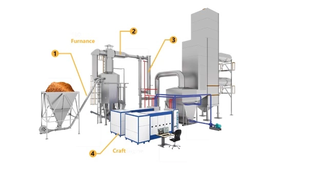
A wood gasifier is a device that converts wood or other biomass materials into a combustible gas called wood gas or syngas. The gas can be used as a fuel for various applications, including heating, cooking, and generating electricity. Here’s a general overview of how a wood gasifier works:
- Fuel Preparation: The wood or biomass material is first processed into small pieces or chips. This allows for better gasification and efficient combustion.
- Pyrolysis: The wood gasifier operates in a low-oxygen environment. The fuel is heated to a high temperature, typically around 700-1,200 degrees Celsius (1,300-2,200 degrees Fahrenheit), causing it to undergo a process called pyrolysis. During pyrolysis, the fuel breaks down into volatile gases, including carbon monoxide (CO), hydrogen (H2), and methane (CH4).
- Combustion Chamber: The pyrolysis gases move into the combustion chamber of the gasifier. The chamber contains a limited supply of oxygen, allowing for partial combustion of the gases. This produces additional heat and carbon dioxide (CO2).
- Gasification: The partially combusted gases, along with the remaining solid char, pass into the gasification zone of the gasifier. In this zone, the remaining carbon monoxide and water vapor react with the char at high temperatures to produce more carbon monoxide and hydrogen. This is the primary stage where the wood gas is formed.
- Gas Cleaning: The gas produced in the gasification zone contains impurities such as tar, ash, and particulate matter. To ensure a clean and usable gas, it undergoes a cleaning process. This may involve passing the gas through filters, scrubbers, or other cleaning mechanisms to remove impurities and cool down the gas.
- Gas Utilization: The cleaned and cooled wood gas can be utilized for various applications. It can be directed to an internal combustion engine, such as a generator or vehicle engine, where it replaces conventional fuels like gasoline or diesel. It can also be used for heating by burning the gas in a furnace or boiler, or for cooking by using specialized wood gas stoves.
How Does a Wood Gasifier Work
Wood gasifiers offer the advantage of utilizing renewable biomass resources, such as wood chips, sawdust, or agricultural waste, for energy production. They provide an alternative energy solution that can be more sustainable and environmentally friendly compared to fossil fuels. However, it’s important to note that operating a wood gasifier requires proper knowledge, maintenance, and safety precautions due to the combustible nature of the produced gas.
Fuel Preparation
Fuel preparation for a wood gasifier involves transforming solid biomass, such as wood chips, into a suitable form for efficient gasification. Proper fuel preparation is important to ensure optimal gasification performance and maximize the energy output. The fuel preparation process typically includes the following steps:
- Size Reduction: The biomass fuel, such as logs, branches, or wood chips, needs to be reduced in size to increase its surface area and facilitate the gasification process. This can be achieved through mechanical methods such as chipping, shredding, or grinding. The size of the fuel particles may vary depending on the specific design and requirements of the gasifier.
- Moisture Content Control: Biomass typically contains moisture, which can negatively affect the gasification process. Excess moisture can reduce the gasifier’s efficiency and decrease the energy output. Therefore, it is important to control and reduce the moisture content of the fuel. This can be done by properly drying the biomass before using it in the gasifier. Drying methods may include air drying, using a kiln, or utilizing solar or thermal energy to remove moisture.
- Size Sorting: Depending on the gasifier design, it may be necessary to sort the fuel particles based on their size. Some gasifiers require a specific particle size range to ensure optimal gasification and prevent issues such as clogging or uneven combustion. Sorting the fuel particles can be done using sieves or screens to separate them into different size fractions.
- Quality Control: Ensuring the quality of the fuel is essential for efficient gasification. It is important to remove any contaminants or non-combustible materials, such as rocks, metals, or excessive bark, from the biomass. These contaminants can interfere with the gasification process and cause damage to the gasifier. Additionally, the fuel should be free from chemical treatments or coatings that could release harmful emissions during gasification.
Proper fuel preparation is crucial for the smooth operation and efficiency of a wood gasifier. It allows for consistent and controlled gasification, leading to reliable energy production. It is recommended to follow the manufacturer’s guidelines and recommendations regarding the fuel specifications and preparation methods for a specific gasifier model.
Pyrolysis
Pyrolysis is a thermal decomposition process that occurs when organic materials are heated in the absence or with limited oxygen. It is a key step in the wood gasification process and plays a crucial role in converting solid biomass into gas and liquid products. During pyrolysis, the organic material undergoes chemical and physical transformations, breaking down into different components.
The pyrolysis process involves several stages:
- Drying: Initially, as the biomass is heated, any moisture present in the material is driven off. The temperature increases, and the biomass starts to release water vapor.
- Degradation: As the temperature continues to rise, the biomass undergoes thermal degradation. The organic material breaks down into solid char, liquid tar, and gases. The exact composition and distribution of these products depend on factors such as temperature, heating rate, and the composition of the biomass.
- Char Formation: The solid char, or carbonaceous residue, is a byproduct of pyrolysis. It consists of carbon-rich material that remains after the volatile components have been released. The char can be further utilized as a source of heat or energy.
- Tar Formation: The liquid tar is a complex mixture of organic compounds that condenses during the pyrolysis process. It contains a range of hydrocarbons and other organic substances. Tar can be sticky and viscous, and it requires further processing or treatment to remove impurities before it can be used.
- Gas Production: The primary gases produced during pyrolysis are carbon monoxide (CO), hydrogen (H2), methane (CH4), and other hydrocarbons. These gases are collectively known as syngas or wood gas. The composition of the syngas depends on various factors, including the type of biomass, temperature, and residence time in the pyrolysis zone.
The pyrolysis process is typically controlled by adjusting the temperature and residence time to achieve the desired gas and liquid products. The generated gases and liquids are valuable energy sources and can be used for various applications, including heating, electricity generation, and as feedstock for the production of chemicals and fuels.
It is important to note that pyrolysis is just one stage of the overall wood gasification process. After pyrolysis, the resulting gases and liquids undergo further reactions and cleaning before they are used as fuel in a gasifier or other combustion devices.
Combustion Chamber
The combustion chamber is a crucial component of various combustion systems, including wood gasifiers, boilers, and furnaces. It is the space where the combustion of fuel takes place, converting the chemical energy of the fuel into heat energy. In the context of a wood gasifier, the combustion chamber is where the wood gas produced during the gasification process is burned.
The main functions of the combustion chamber are as follows:
- Fuel Combustion: The primary purpose of the combustion chamber is to facilitate the controlled combustion of the fuel. In the case of a wood gasifier, the wood gas produced from the gasification process is introduced into the combustion chamber, along with an adequate supply of air or oxygen. The mixture of fuel and oxygen is ignited, and the combustion reaction occurs, releasing heat energy.
- Heat Transfer: The combustion chamber is designed to maximize heat transfer from the combustion process to the surrounding medium, such as water or air. The heat generated by the burning fuel is transferred through the walls of the combustion chamber to the heat transfer medium, which can then be utilized for various purposes, such as space heating, water heating, or electricity generation.
- Combustion Control: The design of the combustion chamber plays a crucial role in achieving efficient and controlled combustion. It involves considerations such as optimizing the air-fuel ratio, maintaining proper turbulence and mixing of fuel and air, and ensuring sufficient residence time for complete combustion. The combustion chamber may have features like baffles, secondary air injection, or other mechanisms to enhance combustion efficiency and minimize emissions.
- Emission Control: The combustion chamber also serves to minimize emissions of harmful pollutants generated during the combustion process. By ensuring complete combustion and providing appropriate conditions for combustion, the combustion chamber helps to reduce the formation of pollutants such as carbon monoxide (CO), nitrogen oxides (NOx), and particulate matter. This is important for environmental and health considerations.
The design and construction of the combustion chamber depend on the specific application, fuel type, desired heat output, and emission requirements. It is important to consider factors such as chamber geometry, insulation, refractory materials, and the provision of air supply and exhaust systems to optimize combustion efficiency and ensure safe and reliable operation. Regular maintenance and cleaning of the combustion chamber are also essential to maintain its performance and prevent the accumulation of ash or soot.
Gasification
Gasification is a thermochemical process that converts solid or liquid carbon-based fuels into a combustible gas known as syngas (synthesis gas). It is a versatile and efficient method of harnessing energy from biomass, coal, or other organic materials. Gasification involves the partial oxidation of the fuel at high temperatures, typically in the range of 700 to 1,200 degrees Celsius (1,300 to 2,200 degrees Fahrenheit), in the presence of a controlled amount of oxygen or air.
The gasification process can be summarized in the following steps:
- Drying: In the initial stage, the feedstock is dried to remove moisture. This is important to ensure efficient gasification and prevent excessive energy loss due to evaporation.
- Pyrolysis: The dried feedstock is then subjected to pyrolysis, which is the thermal decomposition of organic materials in the absence of oxygen. This leads to the release of volatile compounds, including gases, tars, and char.
- Combustion: The next step involves introducing a limited amount of oxygen or air into the gasification reactor. The volatiles released during pyrolysis undergo partial oxidation or combustion, resulting in the production of carbon dioxide (CO2), water vapor (H2O), and heat.
- Gasification: The remaining char and any carbonaceous material present in the feedstock undergo gasification in the presence of the high-temperature environment. This process converts the carbon in the fuel into a mixture of gases, primarily carbon monoxide (CO) and hydrogen (H2), along with traces of methane (CH4) and other hydrocarbons. This gas mixture is known as syngas.
The produced syngas is a valuable fuel that can be used in various applications, including heat and power generation, as well as the production of chemicals and fuels. It can be combusted directly in a gas engine or boiler, or further processed to remove impurities and separate individual components for specific uses.
Gasification offers several advantages over conventional combustion methods:
- Higher Efficiency: Gasification can achieve higher energy conversion efficiencies compared to direct combustion, as it allows for the extraction of more energy from the fuel by converting a larger portion of the carbon content into combustible gases.
- Fuel Flexibility: Gasification can utilize a wide range of feedstock materials, including biomass, coal, municipal solid waste, and even certain types of industrial waste. This makes it a versatile technology that can utilize diverse sources of fuel.
- Reduced Emissions: Gasification can be designed to minimize emissions of pollutants, such as sulfur dioxide (SO2), nitrogen oxides (NOx), and particulate matter. By optimizing the gasification process, it is possible to achieve cleaner combustion and lower environmental impact.
- Syngas Utilization: The syngas produced from gasification can be used in various applications, including electricity generation through gas engines or turbines, combined heat and power (CHP) systems, and as a feedstock for the production of chemicals, fertilizers, and transportation fuels.
Overall, gasification is a versatile and efficient technology for converting carbon-based fuels into a useful gas product. It offers opportunities for sustainable energy production, waste management, and the utilization of diverse fuel sources.
Gas Cleaning
Gas cleaning is an important step in the gasification process to remove impurities and contaminants from the syngas produced. The syngas generated during gasification contains various by-products, such as tars, particulate matter, sulfur compounds, ammonia, and other trace elements, which need to be removed to meet specific quality requirements for different applications.
Gas cleaning typically involves a combination of physical, chemical, and thermal processes to achieve the desired level of purification. The specific gas cleaning methods employed can vary depending on the composition of the syngas and the end-use requirements. Here are some common gas cleaning techniques:
- Particulate Removal: Syngas often contains solid particulate matter, such as ash, char, or dust. Particulate removal techniques, such as cyclone separators, electrostatic precipitators, or bag filters, are used to capture and remove these solid particles from the gas stream.
- Tar Removal: Tar is a complex mixture of organic compounds that can be present in the syngas. Tar can condense and cause fouling or damage to downstream equipment. Tar removal methods include processes like condensation, cooling, and filtration, which help to separate and capture the tar molecules from the gas stream.
- Acid Gas Removal: Syngas may contain sulfur compounds, such as hydrogen sulfide (H2S), which need to be removed to prevent corrosion and reduce environmental emissions. Techniques like amine scrubbing, adsorption, or catalytic conversion are used to selectively capture and remove acid gases from the syngas.
- Particulate Filtration: Fine particulate matter or aerosols present in the syngas can be removed through filtration techniques, such as ceramic filters or porous membranes. These filters effectively trap and separate fine particles, ensuring a cleaner gas stream.
- Water-Gas Shift Reaction: In certain gas cleaning processes, the syngas is subjected to the water-gas shift reaction, where carbon monoxide (CO) is reacted with steam to produce hydrogen (H2) and carbon dioxide (CO2). This reaction helps to adjust the hydrogen-to-carbon monoxide ratio in the syngas and remove excess carbon monoxide.
- Gas Cooling and Condensation: Cooling the syngas helps to remove moisture and condensable components, such as water vapor and light hydrocarbons. By reducing the temperature, these components can be condensed and separated from the gas stream.
The selection and combination of gas cleaning methods depend on factors such as the composition of the syngas, desired gas quality, process requirements, and environmental regulations. The goal of gas cleaning is to produce a purified syngas with the desired composition and properties suitable for its intended use, whether it is for power generation, heat production, or conversion into other valuable products.
Gas Utilization
Gas utilization refers to the various ways in which the syngas produced from gasification is used or converted into valuable products. Syngas is a versatile fuel that can be utilized in several applications, including:
- Power Generation: Syngas can be used as a fuel in gas engines, gas turbines, or combined heat and power (CHP) systems to generate electricity and heat. This is a common application for large-scale gasification plants where the syngas is combusted in an internal combustion engine or turbine to produce mechanical power, which is then converted into electricity.
- Heat Production: Syngas can be used for direct heat applications, such as heating buildings, industrial processes, or district heating systems. The syngas can be burned in a boiler or furnace to generate high-temperature heat for space heating or industrial processes.
- Biochemical Processes: Syngas can be converted into various biochemical products through fermentation or catalytic processes. For example, syngas can be converted into biofuels such as ethanol or methanol, which can be used as transportation fuels or as feedstocks for the chemical industry.
- Chemical Synthesis: Syngas can be used as a feedstock for the production of a wide range of chemicals. Through processes like Fischer-Tropsch synthesis or methanol synthesis, syngas can be converted into valuable chemicals, including hydrocarbons, alcohols, olefins, and other compounds used in the manufacturing of plastics, solvents, and other industrial products.
- Gasification for Biomass-to-Liquid (BTL) Technologies: Syngas can be further processed into liquid fuels through gas-to-liquids (GTL) or biomass-to-liquids (BTL) technologies. These processes involve converting the syngas into synthetic hydrocarbons, such as diesel, jet fuel, or gasoline, through catalytic reactions.
- Gas Grid Injection: In some cases, the syngas can be cleaned and upgraded to meet the quality standards for natural gas and injected into the existing natural gas grid. This allows for the syngas to be distributed and utilized in a wide range of applications that rely on natural gas, including residential, commercial, and industrial sectors.
The specific utilization of syngas depends on factors such as the composition of the syngas, local energy demands, infrastructure availability, and economic considerations. Different gasification technologies and gas cleaning processes can be employed to tailor the syngas composition for the desired utilization pathway.
A wood gasifier is a device that converts wood or other biomass materials into a combustible gas, known as wood gas or syngas. The gas can be used as a fuel for various applications, including heating, cooking, and generating electricity. Here’s how a wood gasifier typically works:
- Fuel Preparation: The wood or biomass material is processed into small pieces or chips to ensure efficient gasification. The size and moisture content of the fuel can affect the gasifier’s performance.
- Gasification Process: The wood gasifier consists of a combustion chamber where the fuel is heated in a low-oxygen environment, a process known as pyrolysis. This leads to the release of volatile gases from the wood, such as carbon monoxide, hydrogen, and methane.
- Gas Cleaning: The gas produced in the combustion chamber contains impurities like tar and particulate matter. It is then passed through a series of filters and cooling systems to remove these impurities and cool down the gas.
- Gas Utilization: The cleaned and cooled wood gas can be directed to various applications. It can be used to power internal combustion engines, such as generators or vehicles, by feeding it into the engine’s intake system. It can also be used for heating purposes by burning the gas in a combustion chamber or stove.
Wood gasifiers offer several advantages, including the ability to use renewable and locally available biomass resources for energy production. They can provide a sustainable and cost-effective energy solution, especially in areas with limited access to conventional fuels. However, it’s important to note that operating a wood gasifier requires proper knowledge and safety precautions due to the combustible nature of the gas produced.
When considering a wood gasifier, it’s essential to choose a model that suits your specific needs, taking into account factors such as power output, fuel consumption, and the availability of maintenance and support services. It’s also important to ensure compliance with local regulations and obtain any necessary permits or certifications before installing and operating a wood gasifier system.
Wood Gasifier for Sale USA
Wood gasifiers are a renewable energy technology that converts wood or biomass into a combustible gas known as wood gas or syngas. This gas can be used for various applications, including heat generation, electricity production, and powering internal combustion engines. If you are considering a wood gasifier for the USA market, here are some important factors to consider:
- Compliance with Regulations: Ensure that the wood gasifier meets all applicable regulations and standards in the USA. This includes safety standards, emission limits, and any specific requirements for wood-burning appliances. It is important to select a wood gasifier that is certified or compliant with relevant regulatory bodies or standards, such as the Environmental Protection Agency (EPA) guidelines.
- Sizing and Capacity: Determine the appropriate size and capacity of the wood gasifier based on your specific energy needs. Consider factors such as the heat or power output required, the availability of wood or biomass feedstock, and the intended application. The size of the wood gasifier will impact its efficiency, fuel consumption, and overall performance.
- Efficiency and Emissions: Look for wood gasifiers that offer high efficiency and low emissions. Efficiency is important to maximize the energy output from the available wood or biomass fuel. Low emissions help minimize the environmental impact and comply with air quality regulations. Consider features such as optimized combustion processes, advanced gas cleaning systems, and integrated emission control technologies.
- Fuel Flexibility: Check if the wood gasifier is designed to handle a variety of wood types and biomass feedstocks. Some gasifiers can accommodate different wood sizes, moisture content, and densities. The ability to use a range of feedstocks provides flexibility in sourcing fuel and ensures reliable operation throughout the year.
- Reliability and Maintenance: Assess the reliability and maintenance requirements of the wood gasifier. Look for systems with a track record of reliable performance and durability. Consider factors such as ease of maintenance, availability of spare parts, and access to technical support or service providers in the USA.
- System Integration and Controls: Consider how the wood gasifier integrates into your overall energy system. Look for features such as control systems, automation, and compatibility with other components, such as heat exchangers or electricity generators. Integration with existing infrastructure and energy management systems can enhance the overall efficiency and functionality of the wood gasifier.
- Training and Support: Ensure that adequate training and support are available for the installation, operation, and maintenance of the wood gasifier. This may include training programs, technical documentation, and access to knowledgeable support personnel. Having reliable support resources can help optimize the performance and longevity of the wood gasifier.
It is advisable to consult with reputable manufacturers, distributors, or industry experts who specialize in wood gasification technology to understand the specific options available in the USA market. They can provide guidance on selecting the most suitable wood gasifier based on your requirements, local regulations, and market availability.
Fuel Preparation
Fuel preparation for a wood gasifier involves properly processing and preparing the wood or biomass fuel before it is fed into the gasifier. The goal is to optimize the fuel’s characteristics to ensure efficient gasification and reliable operation of the system. Here are some important aspects of fuel preparation for a wood gasifier:
- Wood Selection: Choose the right type of wood for gasification. Hardwoods, such as oak, beech, or maple, are generally preferred due to their higher energy content and lower moisture content compared to softwoods. Select wood that is dry, seasoned, and free from contaminants, such as paints, coatings, or treated wood, as these can produce harmful emissions during gasification.
- Wood Size and Density: Prepare the wood fuel by cutting it into appropriate sizes for the gasifier. The wood should be in the form of small chips, pellets, or blocks with dimensions that are suitable for the gasifier’s feed system. The size and density of the wood can impact the gasification process and the gasifier’s performance, so it is important to follow the manufacturer’s guidelines or recommendations.
- Moisture Content: Ensure that the wood fuel has an optimal moisture content. High moisture content in the wood can result in incomplete combustion, reduced gas quality, and decreased overall efficiency. The ideal moisture content may vary depending on the specific gasifier design, but generally, a moisture content of around 10-20% is desirable. Properly drying and storing the wood fuel in a dry environment can help achieve the desired moisture content.
- Fuel Storage: Proper storage of the wood fuel is important to maintain its quality and prevent moisture absorption. Store the wood in a covered and well-ventilated area, protected from rain or excessive humidity. It is also advisable to store the wood in a way that allows for proper air circulation to prevent mold or decay.
- Fuel Processing: Depending on the gasifier design and fuel requirements, additional fuel processing may be necessary. This can include tasks such as debarking, chipping, or grinding the wood to the desired size and form. Some gasifiers may have specific fuel processing equipment or recommendations provided by the manufacturer.
It is essential to follow the gasifier manufacturer’s guidelines and recommendations for fuel preparation to ensure safe and efficient operation. Each gasifier system may have specific requirements based on its design, fuel feed mechanism, and gasification process. Consulting the manufacturer or an experienced professional in wood gasification technology will provide valuable guidance on the appropriate fuel preparation methods for your specific system.
Gasification Process
Gasification is a thermochemical process that converts organic materials, such as wood, biomass, or coal, into a gas known as syngas (synthetic gas). The gasification process involves the partial oxidation of the feedstock at high temperatures in a controlled environment, resulting in the production of a combustible gas mixture. Here is a general overview of the gasification process:
- Feedstock Preparation: The feedstock, such as wood chips, biomass pellets, or coal, is prepared by reducing its size, removing impurities, and ensuring a consistent feedstock quality. Proper feedstock preparation helps optimize the gasification process and improve the efficiency of gas production.
- Heating and Drying: The prepared feedstock is fed into the gasifier, which is a high-temperature reactor. Initially, the feedstock is heated and dried to remove any moisture content. The drying process is important to ensure efficient combustion and prevent excessive energy loss due to evaporating moisture.
- Pyrolysis: In the gasification process, the dried feedstock undergoes pyrolysis, which is the thermal decomposition of organic material in the absence of oxygen. The high temperature in the gasifier breaks down the complex organic compounds into simpler molecules, producing volatile gases, tars, and char.
- Gasification: The pyrolyzed products, including the volatile gases and tars, are then subjected to the gasification phase. In the presence of a controlled amount of oxygen or air, the volatile gases react with the oxygen to produce a mixture of carbon monoxide (CO), hydrogen (H2), methane (CH4), and other combustible gases. This mixture is known as syngas or producer gas.
- Tar and Particulate Removal: The syngas produced in the gasification process contains impurities such as tars and particulate matter. These impurities need to be removed to prevent fouling and damage to downstream equipment. Various cleaning methods, such as cyclones, filters, or scrubbers, are employed to separate and remove the tars and particulates from the syngas.
- Gas Cooling and Conditioning: After the cleaning process, the syngas is typically cooled to reduce its temperature and remove excess heat. It may also undergo further conditioning to adjust its composition, such as removing sulfur compounds or adjusting the gas ratios. This ensures that the syngas meets the desired specifications for specific applications.
- Syngas Utilization: The cleaned and conditioned syngas can be utilized for various applications, depending on the specific requirements. It can be used for heat and power generation in boilers, engines, or turbines. It can also be converted into liquid fuels, such as methanol or synthetic diesel, through additional processes like gas-to-liquids (GTL) technology.
Gasification offers several advantages, including high energy efficiency, fuel flexibility, and reduced emissions compared to conventional combustion processes. The specific details of the gasification process may vary depending on the feedstock, gasifier design, and intended application. Different gasifier technologies, such as fixed-bed gasifiers, fluidized bed gasifiers, or entrained flow gasifiers, may have variations in their operating parameters and process steps.
Gas Cleaning
Gas cleaning is an important step in the gasification process to remove impurities and ensure that the produced syngas meets the required specifications for further utilization. During the gasification process, various contaminants can be present in the syngas, including tars, particulates, sulfur compounds, and other trace elements. Gas cleaning involves the use of different technologies and methods to purify the syngas by removing these impurities. Here are some common gas cleaning techniques:
- Cyclones: Cyclone separators are used to remove particulate matter, such as ash, char, and dust, from the syngas. The gas is passed through a cyclone chamber, where centrifugal force causes the particles to separate and settle down.
- Filters: Filters, such as fabric filters or ceramic filters, are used to capture and remove fine particulate matter from the syngas. These filters operate based on various mechanisms, including mechanical filtration, electrostatic precipitation, or ceramic candle filtration.
- Wet Scrubbers: Wet scrubbers are used to remove tars and other organic compounds from the syngas. The gas is passed through a scrubbing liquid, typically water or a solvent, which captures the contaminants through absorption or chemical reaction.
- Gas Washing: Gas washing involves using a liquid, such as water or a solvent, to wash the syngas and remove impurities. This method is effective in removing water-soluble contaminants and can also help to reduce the gas temperature.
- Catalytic Conversion: Catalytic conversion processes utilize catalysts to convert or break down specific contaminants in the syngas. For example, sulfur compounds can be converted into hydrogen sulfide (H2S) and then removed using scrubbing techniques.
- Adsorption: Adsorption involves passing the syngas through adsorbent materials, such as activated carbon or zeolites, which have a high affinity for specific contaminants. The adsorbents capture the impurities, allowing the purified syngas to pass through.
- Tar Cracking: Tar cracking is a process where tars present in the syngas are thermally decomposed or cracked into simpler molecules. This can be achieved by subjecting the syngas to high temperatures in a secondary reactor or through the use of catalytic cracking.
The selection of gas cleaning methods depends on factors such as the composition of the impurities, desired syngas specifications, process conditions, and the intended end-use of the syngas. Gas cleaning technologies can be combined and tailored to meet specific requirements and ensure the syngas quality is suitable for subsequent utilization, such as power generation, heat production, or conversion into synthetic fuels.
Gas Utilization
Gas utilization refers to the process of utilizing the syngas (synthetic gas) produced from gasification for various applications. Syngas is a mixture of carbon monoxide (CO), hydrogen (H2), carbon dioxide (CO2), and other trace gases, depending on the specific gasification process and feedstock used. Here are some common applications of syngas utilization:
- Power Generation: Syngas can be used as a fuel in gas turbines or internal combustion engines to generate electricity. The syngas is burned in the combustion chamber, and the heat energy is converted into mechanical energy, which is then used to drive a generator.
- Heat Production: Syngas can be combusted in boilers or furnaces to produce heat for various industrial processes, district heating systems, or space heating applications. The heat energy released during the combustion of syngas can be used directly or transferred to a heat transfer fluid for further distribution.
- Biofuel Production: Syngas can be further processed to produce liquid biofuels, such as synthetic diesel or synthetic gasoline. This typically involves additional steps, such as Fischer-Tropsch synthesis, where the syngas is converted into hydrocarbon fuels through catalytic reactions.
- Chemical Synthesis: Syngas can serve as a feedstock for the production of various chemicals and materials. For example, it can be used as a precursor for the synthesis of methanol, ammonia, methanol-to-olefins (MTO) processes, and other chemical reactions that utilize carbon monoxide and hydrogen.
- Hydrogen Production: Syngas can be reformed or processed further to produce high-purity hydrogen gas, which has applications in fuel cells, chemical processes, and transportation.
- Combined Heat and Power (CHP) Systems: Syngas can be used in combined heat and power systems, where the heat produced during power generation or other processes is captured and utilized for heating purposes, maximizing overall energy efficiency.
- Syngas Injection: Syngas can be injected into natural gas pipelines and used as a blend with natural gas for heating or power generation. This can help reduce greenhouse gas emissions and utilize renewable or carbon-neutral feedstocks.
The choice of syngas utilization depends on factors such as the composition of the syngas, local energy needs, infrastructure availability, and economic considerations. The syngas may require further purification or conditioning depending on the specific application and requirements.
Wood Gasifier
A wood gasifier is a device that converts wood or biomass into a combustible gas called syngas, also known as wood gas or producer gas. This gas can be used to power engines, generators, or for heating purposes. Wood gasifiers are a relatively simple and efficient way to utilize biomass as a fuel source.
Working Principle of a Wood Gasifier:
- Charring: In the primary chamber, wood is heated to a high temperature without oxygen, causing it to decompose into charcoal and pyrolysis gas.
- Gasification: The charcoal and pyrolysis gas enter the gasification chamber, where they are further heated in the presence of oxygen. This generates syngas, a mixture of carbon monoxide, hydrogen, and methane.
- Cleaning and Conditioning: The syngas passes through a cleaning and conditioning stage to remove impurities like tars and particulate matter.
- Burning or Utilization: The clean syngas can then be used to power engines, generators, or for heating purposes.
Advantages of Wood Gasification:
- Self-Sufficiency: Wood gasifiers can be used to utilize biomass resources locally, providing a source of renewable energy for rural communities or individuals.
- Fuel Flexibility: Wood gasifiers can operate on a variety of wood types, including both hardwood and softwood. They can also be used with other biomass feedstocks, such as agricultural residues and yard waste.
- Combustion Efficiency: Wood gasifiers can achieve high combustion efficiencies, converting up to 70% of the biomass feedstock into syngas.
- Reduced Emissions: Compared to direct combustion of wood, wood gasification can significantly reduce emissions of particulate matter, carbon monoxide, and other pollutants.
Disadvantages of Wood Gasification:
- Complexity and Maintenance: Wood gasifiers are more complex than traditional wood-burning stoves or fireplaces and require regular maintenance to ensure optimal performance.
- Tar Formation: The gasification process can produce tars, which can accumulate in the gasifier and hinder its operation. Regular cleaning is necessary to prevent tar buildup.
- Storage and Handling: Syngas is a flammable gas and requires careful storage and handling to prevent leaks and potential safety hazards.
- Energy Conversion Efficiency: While wood gasifiers can achieve high combustion efficiencies, the overall energy conversion efficiency from wood to syngas and then to useful work is still lower than some other energy conversion technologies.
Applications of Wood Gasifiers:
- Power Generation: Wood gasifiers can be used to power engines and generators to produce electricity.
- Heating Applications: Wood gasifiers can be used to provide heat for homes, businesses, and industrial applications.
- Cooking and Heating: Wood gasifiers can be used to provide cooking fuel and heating for household or small-scale applications.
Safety Considerations for Wood Gasifiers:
- Secure Installation: Wood gasifiers must be installed in a well-ventilated and secure location to prevent gas leaks and potential explosions.
- Regular Maintenance: Wood gasifiers require regular maintenance to ensure optimal operation and prevent safety issues.
- Proper Storage and Handling: Syngas is a flammable gas and must be stored and handled safely to prevent leaks and ignition hazards.
- Operator Training: Individuals operating wood gasifiers should receive proper training on safety procedures and maintenance requirements.
- Local Regulations: Check local regulations and building codes regarding the installation and operation of wood gasifiers in your area.
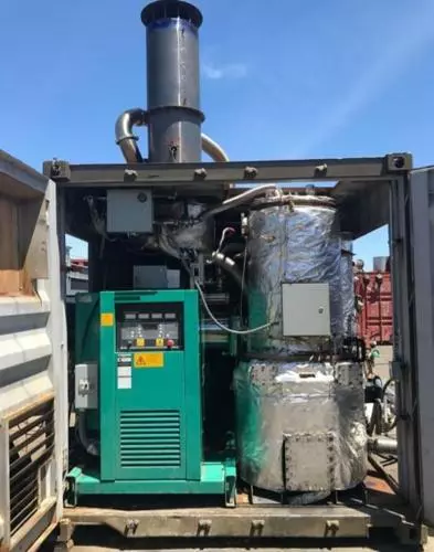
We manufacture Off-grid Biomass Generator for Electricity Production. Electricity generation from steam by burning woodchip and wood pellet. Free Consultation
An off-grid biomass generator is a type of generator that produces electricity using biomass fuel and is not connected to the electric grid. These generators can be used in remote locations or in areas where access to the grid is limited or non-existent.
Off-grid biomass generators operate in much the same way as other types of biomass generators, by converting organic waste or biomass material into electricity. This involves fuel handling and preparation, gasification, combustion, and ash removal, as described in my previous response.
The key difference with off-grid biomass generators is that they are designed to operate independently of the electric grid, using batteries or other energy storage systems to store excess electricity for later use. This allows users to generate their own electricity and reduce reliance on the grid, while providing a reliable source of power in areas where the grid is unreliable or non-existent.
Off-grid biomass generators can be used for a variety of applications, including remote power generation for homes, farms, or businesses, as well as for emergency backup power in the event of grid outages or natural disasters.
While off-grid biomass generators offer many benefits, they also come with some challenges. For example, proper fuel selection and handling are critical to ensure efficient and reliable operation, and maintenance requirements can be significant. Additionally, energy storage systems can be expensive and may require regular maintenance to ensure proper operation. Overall, the use of off-grid biomass generators requires careful planning and consideration to ensure effective and reliable operation.
Advantages and Disadvantages
Advantages of off-grid biomass generators:
- Energy independence: Off-grid biomass generators provide energy independence to users, allowing them to generate their own electricity and reduce reliance on the grid.
- Renewable energy source: Biomass is a renewable energy source, meaning it can be replenished over time. This makes it a more sustainable energy source compared to fossil fuels, which are finite resources.
- Reduced greenhouse gas emissions: Biomass generators produce less greenhouse gas emissions compared to fossil fuel generators. This is because biomass is a carbon-neutral fuel, meaning the carbon dioxide released during combustion is offset by the carbon dioxide absorbed during the biomass material’s growth.
- Local availability: Biomass material is widely available and can often be sourced locally, reducing transportation costs and increasing energy security.
Disadvantages of off-grid biomass generators:
- High capital costs: Off-grid biomass generators can be expensive to purchase and install, especially for larger systems.
- Maintenance requirements: Biomass generators require regular maintenance to ensure efficient and reliable operation. This can include cleaning and maintenance of the gasifier and engine components, as well as ash removal and fuel handling.
- Fuel variability: The composition and quality of biomass fuel can vary significantly depending on the source and preparation. This can affect the efficiency and reliability of the generator, and require careful fuel selection and handling.
- Land use and biodiversity impacts: The production of biomass fuel can have impacts on land use and biodiversity, especially if biomass crops are grown on land that was previously used for other purposes.
Overall, off-grid biomass generators offer many benefits as a renewable energy source, but also come with some challenges that need to be carefully managed. Proper fuel selection, handling, and maintenance are important to ensure efficient and reliable operation, while minimizing environmental impacts. Additionally, the high capital costs of these systems may limit their use in certain applications, and careful consideration of the potential impacts on land use and biodiversity is important.
Application Areas
Off-grid biomass generators can be used in a wide range of applications, including:
- Remote power generation: Off-grid biomass generators can provide reliable and sustainable electricity to remote locations where grid connections are not available or are unreliable. This includes powering remote communities, off-grid cabins, and other remote facilities such as communication towers and weather stations.
- Agriculture and forestry: Off-grid biomass generators can be used in agriculture and forestry settings to power equipment such as irrigation pumps, sawmills, and grain dryers.
- Emergency backup power: Off-grid biomass generators can be used as backup power in the event of grid outages or natural disasters. This is particularly important for critical facilities such as hospitals, emergency response centers, and water treatment facilities.
- Industrial applications: Off-grid biomass generators can be used to power industrial processes such as manufacturing, food processing, and mining.
- Microgrids: Off-grid biomass generators can be used as part of a microgrid, where they can work in conjunction with other renewable energy sources such as solar and wind power to provide reliable and sustainable electricity to a community or facility.
- Residential and commercial power: Off-grid biomass generators can be used to provide electricity to individual homes and businesses in areas where grid connections are not available or are unreliable.
Overall, off-grid biomass generators are versatile and can be used in a wide range of applications, providing reliable and sustainable electricity in areas where grid connections are limited or non-existent.
Small-scale biomass generators are systems that convert biomass, such as wood, agricultural waste, or municipal solid waste, into usable energy at a smaller capacity compared to large-scale power plants. They typically range in power output from a few kilowatts to a few megawatts and are often used in rural or remote areas where grid access is limited or unreliable.
Types of Small-Scale Biomass Generators:
- Direct Combustion Generators: These generators directly burn biomass in a boiler to produce hot water or steam, which can then be used for various applications, such as space heating, hot water production, or power generation.
- Gasification Generators: These generators convert biomass into syngas through a thermochemical process and then use the syngas to drive an internal combustion engine or a gas turbine to generate electricity.
- Biogas Generators: These generators utilize organic waste to produce biogas, a mixture of methane and carbon dioxide, through anaerobic digestion. The biogas can be burned to generate heat or electricity.
Applications of Small-Scale Biomass Generators:
- Residential and Commercial Heating: Small-scale biomass generators can provide heating for homes, businesses, and community centers.
- Off-Grid Power Generation: These generators can provide electricity to remote areas without access to the grid.
- Industrial Process Heat: Biomass generators can provide heat for industrial processes, such as drying, sterilization, and food processing.
- Combined Heat and Power (CHP) Systems: Small-scale CHP systems can simultaneously produce electricity and heat from biomass, maximizing energy efficiency.
- Waste Utilization: Biomass generators can utilize agricultural waste, municipal solid waste, and forestry residues, reducing the need for landfills.
Advantages of Small-Scale Biomass Generators:
- Renewable Energy Source: Biomass is a renewable energy source that can be replenished naturally.
- Reduced Reliance on Fossil Fuels: Small-scale biomass generators can reduce dependence on fossil fuels and contribute to a cleaner energy future.
- Local Energy Production: These generators can provide energy locally, reducing reliance on long-distance transmission infrastructure.
- Waste Management: Biomass generators can utilize waste materials, reducing their environmental impact and providing economic benefits.
- Economic Development: Small-scale biomass projects can create jobs and boost local economies in rural areas.
Challenges of Small-Scale Biomass Generators:
- Fuel Supply and Logistics: Ensuring a consistent supply of biomass fuel can be challenging, especially in remote areas.
- Emissions Control: Biomass combustion can produce air pollutants, requiring proper emission control systems.
- Maintenance and Reliability: Small-scale biomass generators require regular maintenance to ensure efficient operation and prevent malfunctions.
- Cost-Effectiveness: The initial investment cost for small-scale biomass generators can be higher than traditional energy sources.
- Sustainable Practices: Sustainable biomass harvesting and utilization practices are crucial to avoid negative environmental impacts.
Future Directions:
Research and development efforts are focused on improving the efficiency, environmental performance, and cost-effectiveness of small-scale biomass generators. This includes developing advanced combustion and gasification technologies, optimizing fuel preparation methods, and exploring innovative applications for syngas and biogas. Small-scale biomass generators are expected to play an increasingly important role in providing sustainable energy solutions for rural communities and off-grid applications.
Direct Combustion Generators
Direct combustion generators are a type of biomass generator that converts biomass directly into heat or steam through combustion. They are a simple and mature technology that is widely used in various applications, including residential and commercial heating, industrial process heat, and power generation.
Working Principle of Direct Combustion Generators:
- Fuel Preparation: Biomass fuel, such as wood pellets, wood chips, or agricultural waste, is prepared by drying and sizing to ensure efficient combustion.
- Fuel Feeding: The prepared biomass is fed into a combustion chamber, where it is ignited and burned.
- Heat Release: The combustion process releases heat, which is transferred to a heat exchanger or boiler.
- Heat Utilization: The heat from the heat exchanger or boiler can be used directly for applications like space heating or hot water production, or it can be used to generate steam for power generation or industrial processes.
Types of Direct Combustion Generators:
- Stoker-fired Boilers: Stoker-fed boilers utilize mechanical devices to move the biomass fuel into the combustion chamber and maintain a consistent burn rate.
- Fluidized Bed Boilers: Fluidized bed boilers suspend biomass particles in a stream of air, creating a highly turbulent environment for efficient combustion.
- Pellet Boilers: Pellet boilers are designed specifically for burning wood pellets, offering high efficiency and compact design.
Advantages of Direct Combustion Generators:
- Simplicity and Maturity: Direct combustion generators are a well-established technology with relatively simple operation and maintenance requirements.
- Fuel Versatility: These generators can utilize a variety of biomass fuels, including wood, agricultural waste, and municipal solid waste.
- High Efficiency: Direct combustion generators can achieve high thermal efficiencies, converting a significant portion of the biomass fuel’s energy into usable heat or steam.
- Cost-Effectiveness: The initial investment and operating costs of direct combustion generators are generally lower compared to other biomass conversion technologies.
Challenges of Direct Combustion Generators:
- Emissions Control: Combustion of biomass can produce air pollutants, such as particulate matter, nitrogen oxides, and sulfur dioxide, requiring emission control systems to meet environmental regulations.
- Fuel Quality: The quality of the biomass fuel can impact the efficiency and emissions of the generator. High moisture content and impurities in the fuel can lead to incomplete combustion and increased emissions.
- Ash Handling: Combustion of biomass produces ash, which needs to be collected and disposed of properly to avoid environmental impacts.
- Fuel Storage: Biomass fuel requires proper storage facilities to prevent moisture absorption and deterioration, which can affect its combustion properties.
- Space Requirements: Direct combustion generators can be larger and require more space compared to some other biomass conversion technologies.
Future Prospects:
Direct combustion generators are expected to continue playing a significant role in the utilization of biomass for energy production. Technological advancements focus on improving combustion efficiency, emission control systems, and fuel preparation methods to enhance the environmental performance and cost-effectiveness of these generators. Direct combustion generators are particularly well-suited for applications where simplicity, fuel versatility, and high thermal efficiency are priorities.
Gasification Generators
Gasification generators are a type of biomass generator that converts biomass into a combustible gas called syngas through a thermochemical process. Syngas is a mixture of primarily carbon monoxide, hydrogen, and methane, which can be used to generate electricity, heat, or liquid fuels. Gasification generators offer several advantages over direct combustion generators, including higher efficiency, lower emissions, and greater versatility.
Working Principle of Gasification Generators:
- Feedstock Preparation: Biomass feedstock, such as wood, agricultural waste, or municipal solid waste, undergoes preparation processes like drying, sizing, and pre-treatment to ensure efficient gasification.
- Gasification Reactor: The prepared biomass feedstock is fed into a gasification reactor, where it is heated in a controlled environment with limited oxygen.
- Thermochemical Reactions: The thermochemical reactions in the gasifier break down the biomass into a mixture of gases primarily composed of carbon monoxide, hydrogen, and methane, forming syngas.
- Syngas Purification: The syngas is passed through a purification system to remove impurities and contaminants, such as tar, water vapor, and sulfur compounds.
- Syngas Utilization: The purified syngas can be used for various applications, including:
- Electricity Generation: Syngas can be used to drive internal combustion engines or gas turbines to generate electricity.
- Heat Production: Syngas can be burned directly to produce heat for industrial processes, space heating, or hot water production.
- Liquid Fuel Production: Syngas can be processed further to produce liquid fuels, such as methanol or Fischer-Tropsch fuels.
Types of Gasification Technologies:
- Fixed Bed Gasification: Biomass feedstock is fed into a stationary bed, where it is gasified by a stream of hot gas or air.
- Fluidized Bed Gasification: Biomass particles are suspended in a stream of hot gas, creating a highly turbulent environment for efficient gasification.
- Entrained Flow Gasification: Biomass particles are fed into a high-velocity stream of hot gas, allowing for rapid gasification and high energy density.
Advantages of Gasification Generators:
- Higher Efficiency: Gasification generators can achieve higher energy conversion efficiencies compared to direct combustion, converting a larger portion of the biomass fuel’s energy into usable syngas.
- Lower Emissions: Gasification can produce lower emissions of air pollutants, such as particulate matter and nitrogen oxides, compared to direct combustion.
- Fuel Versatility: Gasification can utilize a wider range of biomass feedstocks, including low-quality or unconventional biomass sources.
- Syngas Versatility: Syngas can be used for a variety of applications, including electricity generation, heat production, and liquid fuel production.
- Environmental Benefits: Gasification can contribute to reduced reliance on fossil fuels and minimize the environmental impact of biomass utilization.
Challenges of Gasification Generators:
- Technological Complexity: Gasification technology is more complex than direct combustion, requiring specialized equipment and expertise for operation and maintenance.
- Feedstock Preparation: Proper preparation of the biomass feedstock is crucial for efficient gasification and syngas quality.
- Emission Control Systems: While gasification generally produces lower emissions, additional emission control systems may be required to meet environmental standards.
- Syngas Conditioning: Syngas may require conditioning processes, such as cooling and purification, to ensure compatibility with downstream applications.
- Cost Considerations: Gasification generators typically have higher initial investment costs compared to direct combustion generators.
Future Prospects:
Gasification technology is expected to play an increasingly important role in the utilization of biomass for sustainable energy production. Research and development efforts focus on improving gasification efficiency, reducing emission levels, and developing cost-effective syngas conditioning processes. Gasification generators are particularly well-suited for applications where high efficiency, low emissions, and fuel versatility are paramount.
Biogas Generators
Biogas generators are a type of biomass generator that converts organic waste into biogas, a mixture of primarily methane and carbon dioxide, through anaerobic digestion. Biogas can be burned to generate electricity, heat, or transport fuel.
Working Principle of Biogas Generators:
- Digester: Organic waste, such as agricultural waste, food scraps, or municipal solid waste, is placed in an enclosed digester.
- Anaerobic Digestion: Anaerobic bacteria break down the organic waste in the absence of oxygen, producing biogas and digestate.
- Biogas Separation: The biogas is separated from the digestate and purified to remove impurities, such as hydrogen sulfide and ammonia.
- Biogas Utilization: The purified biogas can be used for various applications, including:
- Electricity Generation: Biogas can be burned to drive turbines or engines to generate electricity.
- Heat Production: Biogas can be burned directly to produce heat for industrial processes, space heating, or hot water production.
- Transport Fuel Production: Biogas can be compressed into biomethane, which can be used as a vehicle fuel.
Types of Biogas Digesters:
- Fixed-dome Digesters: These digesters have a semi-circular shape and are commonly used for small-scale applications.
- Floating-cover Digesters: These digesters have a floating cover that rises and falls with the biogas volume, allowing for efficient gas collection.
- Plug-flow Digesters: These digesters have a long, narrow shape, allowing for efficient mixing and digestion of the organic waste.
Advantages of Biogas Generators:
- Renewable Energy Source: Biogas is a renewable energy source that can be produced from various organic waste streams.
- Lower Emissions: Biogas combustion produces lower emissions of carbon dioxide compared to fossil fuels.
- Waste Utilization: Biogas generators can utilize organic waste, reducing the need for landfills.
- Local Energy Production: Biogas generators can be located near waste sources, minimizing transportation costs.
- Environmental Benefits: Biogas production can contribute to reduced reliance on fossil fuels and a more sustainable waste management system.
Challenges of Biogas Generators:
- Waste Availability: Availability of organic waste can be limited or seasonal, affecting biogas production consistency.
- Digestion Process: The anaerobic digestion process can be sensitive to temperature, moisture content, and the type of waste.
- Infrastructure Costs: Developing and maintaining biogas infrastructure, such as digesters and gas collection systems, can be costly.
- Emission Control: While biogas combustion produces lower emissions, additional emission control systems may be required to meet environmental standards.
- Economic Viability: The economic viability of biogas production depends on factors such as waste availability, gas sales, and government incentives.
Future Prospects:
Biogas technology is expected to play an increasingly important role in the utilization of organic waste for renewable energy production and sustainable waste management. Research and development efforts focus on improving biogas production efficiency, reducing costs, and developing innovative applications for biogas, such as grid-scale electricity generation and synthetic fuel production. Biogas generators are particularly well-suited for applications where waste utilization, carbon reduction, and local energy production are priorities.
Wood as Biomass and Wood Fired Steam Power Generators
Wood-fired steam generators can be used to generate electricity in a variety of settings, particularly in off-grid or remote locations where access to the grid is limited or non-existent. These systems typically operate by burning wood or other biomass materials to generate steam, which then drives a turbine connected to an electric generator. The heat produced by the combustion of wood is used to create steam, which is then used to generate electricity.
Wood-fired steam generators can be used in a wide range of applications, including:
- Remote power generation: Wood-fired steam generators can provide reliable and sustainable electricity to remote locations where grid connections are not available or are unreliable. This includes powering remote communities, off-grid cabins, and other remote facilities such as communication towers and weather stations.
- Agriculture and forestry: Wood-fired steam generators can be used in agriculture and forestry settings to power equipment such as irrigation pumps, sawmills, and grain dryers.
- Emergency backup power: Wood-fired steam generators can be used as backup power in the event of grid outages or natural disasters. This is particularly important for critical facilities such as hospitals, emergency response centers, and water treatment facilities.
- Industrial applications: Wood-fired steam generators can be used to power industrial processes such as manufacturing, food processing, and mining.
- Microgrids: Wood-fired steam generators can be used as part of a microgrid, where they can work in conjunction with other renewable energy sources such as solar and wind power to provide reliable and sustainable electricity to a community or facility.
Overall, wood-fired steam generators offer a renewable and sustainable way to generate electricity in a variety of settings, particularly in off-grid or remote locations. However, it is important to carefully manage the sourcing and handling of wood or other biomass materials to ensure sustainable and environmentally responsible operations.
Advantages and Disadvantages
Advantages of wood-fired steam generators for electricity include:
- Renewable and sustainable: Wood is a renewable resource that can be sustainably sourced, making it an environmentally friendly option for electricity generation.
- Versatile: Wood-fired steam generators can be used in a wide range of applications, including remote locations, industrial settings, and emergency backup power.
- Reliable: Once operational, wood-fired steam generators can provide reliable and continuous power, reducing dependence on fossil fuels and grid connections.
- Local economic benefits: Sourcing and processing wood for fuel can provide economic benefits to local communities and businesses.
- Carbon-neutral: When sustainably sourced and managed, wood-fired steam generators can be carbon-neutral or even carbon-negative, meaning they have a net positive impact on the environment.
Disadvantages of wood-fired steam generators for electricity include:
- Fuel sourcing and handling: Sourcing and handling of wood for fuel can be labor-intensive and may require significant infrastructure and transportation costs.
- Emissions: While wood is a renewable resource, combustion of wood does produce emissions, including particulate matter and greenhouse gases, which can contribute to air pollution and climate change.
- Equipment maintenance: Wood-fired steam generators require regular maintenance and cleaning to ensure efficient and safe operations.
- Capital costs: The capital costs associated with purchasing and installing a wood-fired steam generator can be higher than other types of renewable energy systems.
- Fuel availability: Availability of fuel sources may be limited in some areas, particularly in urban or densely populated areas.
Overall, wood-fired steam generators offer a renewable and sustainable option for electricity generation in a variety of settings, but careful consideration should be given to fuel sourcing, emissions, and equipment maintenance to ensure safe and environmentally responsible operations.
Application Areas
Wood-fired steam generators for electricity can be used in a variety of application areas, including:
- Remote locations: Wood-fired steam generators can be used to provide off-grid power in remote locations, such as rural communities or mining operations.
- Industrial settings: Wood-fired steam generators can be used to provide process heat and power in industrial settings, such as sawmills or pulp and paper mills.
- Emergency backup power: Wood-fired steam generators can provide emergency backup power in the event of a power outage, particularly in areas prone to natural disasters or other disruptions to the grid.
- Heating and cooling: Wood-fired steam generators can be used in conjunction with absorption chillers to provide both heat and cooling in buildings, particularly in larger commercial or industrial buildings.
- Microgrids: Wood-fired steam generators can be integrated into microgrid systems, which combine multiple sources of renewable energy to provide reliable and sustainable power to small communities or groups of buildings.
Overall, wood-fired steam generators for electricity offer a versatile and sustainable option for power generation in a variety of settings, particularly in areas where access to the grid is limited or unreliable.
Wood fired steam generators for electricity
Wood-fired steam generators for electricity generation are systems that use wood or biomass as a fuel source to produce high-pressure steam. This steam is then used to drive a steam turbine connected to an electrical generator, producing electricity. This process is a form of biomass power generation and can be an environmentally friendly and sustainable way to generate electricity. Here’s how wood-fired steam generators for electricity work:
- Fuel Supply: The primary fuel for these generators is wood or biomass. Biomass can include wood chips, sawdust, wood pellets, agricultural residues, or other organic materials. The biomass fuel is stored in a designated area and fed into a combustion chamber.
- Combustion: In the combustion chamber, the biomass fuel is burned to produce high-temperature gases. This combustion process releases energy in the form of heat. The heat generated from burning wood is used to heat water, turning it into steam.
- Boiler: The steam generator includes a boiler where water is heated to produce steam. The hot gases from the combustion chamber pass through tubes or other heat exchange surfaces within the boiler, transferring their heat to the water. The water is typically stored in a high-pressure vessel.
- Steam Production: As the water absorbs heat from the combustion gases, it turns into high-pressure steam. The pressure of the steam can vary depending on the system design but is usually in the range of 100 to 500 psi (pounds per square inch).
- Steam Turbine: The high-pressure steam is directed to a steam turbine. Steam turbines are rotary machines with blades attached to a rotor. The expanding steam flows over the turbine blades, causing them to spin. The spinning turbine rotor is connected to an electrical generator.
- Electricity Generation: The rotation of the turbine rotor drives the electrical generator, which converts mechanical energy into electrical energy. The generator produces alternating current (AC) electricity.
- Power Distribution: The generated electricity can be distributed for use in homes, businesses, or industries through a power distribution grid.
Key considerations for wood-fired steam generators for electricity:
- Fuel Sustainability: Using wood or biomass as a fuel source can be sustainable if the biomass is sourced responsibly and replanted to maintain a renewable supply.
- Efficiency: The efficiency of the system depends on the combustion efficiency, boiler design, and turbine efficiency. Well-designed systems can achieve high overall efficiency.
- Environmental Impact: Biomass power generation is considered a renewable energy source and can have lower greenhouse gas emissions compared to fossil fuels when managed sustainably.
- Emissions Control: Emissions from wood combustion should be monitored and controlled to minimize air pollution.
- Scale: These systems can range in size from small decentralized units providing power for a single facility to larger installations for utility-scale electricity generation.
- Maintenance: Regular maintenance and cleaning of the system are necessary to ensure efficient operation and prevent issues related to ash buildup and corrosion.
Wood-fired steam generators for electricity can be a viable option for regions with access to abundant biomass resources and can contribute to reducing dependence on fossil fuels for power generation. However, careful planning, fuel sustainability, and emissions control are essential considerations when implementing such systems.
Wood Fired Steam Generators for Electricity
Wood-fired steam generators, also known as biomass-fired steam boilers, are systems that utilize wood as a fuel to generate steam for various applications, including electricity production. They offer a renewable and environmentally friendly alternative to fossil fuel-based steam generators.
Working Principle:
- Wood Combustion: Wood is fed into a combustion chamber where it is burned to release heat. This heat is transferred to water circulating through tubes or coils within the boiler.
- Water Evaporation: The heat from the burning wood causes the water to evaporate, forming steam. The steam pressure within the boiler increases as more water evaporates.
- Steam Generation: The pressurized steam is then directed to a steam turbine, where its kinetic energy is converted into mechanical energy. The mechanical energy from the turbine drives an electrical generator, producing electricity.
Advantages of Wood-Fired Steam Generators:
- Renewable Energy Source: Wood is a renewable energy source, unlike fossil fuels that are finite and contribute to greenhouse gas emissions.
- Environmentally Friendly: Wood burning produces fewer pollutants compared to fossil fuels, reducing the environmental impact of electricity generation.
- Locally Sourced Fuel: Wood is often available locally, minimizing transportation costs and supporting local economies.
- Waste Utilization: Wood-fired steam generators can utilize wood waste from forestry operations, reducing the need for landfills.
- Carbon-Neutral Operation: When wood is sourced from sustainably managed forests, the carbon emissions from combustion are offset by carbon sequestration through new tree growth.
Applications of Wood-Fired Steam Generators:
- Electricity Generation: Wood-fired steam generators are used in power plants to generate electricity for commercial, industrial, and residential use.
- Industrial Process Heat: Wood-fired steam generators can provide process heat for various industries, such as papermaking, food processing, and textile manufacturing.
- District Heating Systems: Wood-fired steam generators can supply heat for district heating systems, providing warm water or steam to buildings in a centralized manner.
- Combined Heat and Power (CHP) Plants: Wood-fired steam generators can be integrated into CHP plants, producing both electricity and heat from a single fuel source.
- Off-Grid Power Generation: Wood-fired steam generators can be employed in remote or off-grid locations, providing a reliable source of electricity without relying on the grid.
Challenges and Considerations:
- Fuel Moisture Content: High moisture content in wood can reduce boiler efficiency and increase emissions.
- Fuel Preparation: Wood requires proper preparation, such as drying and sizing, to ensure consistent combustion and efficient steam generation.
- Ash Handling: Wood combustion generates ash, which needs to be collected and disposed of properly.
- Emission Control Systems: Wood-fired steam generators may require emission control systems to comply with environmental regulations.
- Fuel Availability and Cost: The availability and cost of wood fuel can vary depending on location and market conditions.
Future Prospects:
Wood-fired steam generators are expected to play an increasingly important role in the transition towards a more sustainable energy future. Technological advancements in combustion efficiency, emission control systems, and fuel preparation are further enhancing the attractiveness of wood-fired steam generators for electricity generation and industrial applications. As the demand for renewable energy sources grows, wood-fired steam generators are poised to make a significant contribution to a cleaner and more sustainable energy mix.
Wood Combustion

Wood combustion is a complex process that involves a series of chemical reactions that convert wood into heat, gases, and ashes. The specific reactions and products depend on various factors, including the type of wood, the combustion conditions, and the presence of catalysts or inhibitors.
Stages of Wood Combustion:
- Drying: The first stage of wood combustion is drying, where the moisture in the wood is evaporated. This endothermic process requires heat from the surrounding environment.
- Devolatilization: As the temperature increases, the wood undergoes devolatilization, where volatile gases are released from the wood. These gases primarily consist of carbon monoxide, methane, and hydrogen.
- Char Formation: The remaining solid material after devolatilization is called char. Char is primarily composed of carbon and some inorganic compounds.
- Char Combustion: The char reacts with oxygen in the air to release heat and produce carbon dioxide. This exothermic reaction is the primary source of heat energy from wood combustion.
- Ash Formation: A small amount of ash is produced during wood combustion, consisting of inorganic compounds that were present in the wood. The composition of ash varies depending on the wood species.
Factors Affecting Wood Combustion:
- Wood Type: Different wood types have varying moisture content, volatile matter content, and char content, which influence the combustion process and properties.
- Combustion Temperature: The combustion temperature significantly impacts the rate of combustion and the formation of combustion products. Higher temperatures generally lead to faster combustion and more complete combustion.
- Oxygen Availability: Oxygen availability is crucial for sustained combustion. Insufficient oxygen can lead to incomplete combustion, producing carbon monoxide and other undesirable products.
- Catalytic Effects: The presence of certain substances, such as minerals in the wood or additives in the combustion environment, can act as catalysts, accelerating the combustion reactions.
- Inhibiting Effects: Certain substances, such as flame retardants or combustion inhibitors, can slow down or prevent combustion by interfering with the chemical reactions.
Applications of Wood Combustion:
- Heating: Wood combustion is a traditional and widely used method for heating homes, businesses, and industrial facilities.
- Power Generation: Wood-fired boilers are used to generate steam for electricity production.
- Cooking: Wood combustion is still used for cooking in many parts of the world, providing a readily available and affordable fuel source.
- Industrial Processes: Wood combustion is employed in various industrial processes, such as wood drying, pulp and paper production, and food processing.
- Biomass Energy: Wood is a significant source of biomass energy, offering a renewable alternative to fossil fuels.
Environmental Considerations:
While wood combustion is considered a more environmentally friendly alternative to fossil fuels, it still produces emissions, including carbon dioxide, particulate matter, and nitrogen oxides. Proper combustion practices, emission control systems, and sustainable forestry practices can help minimize the environmental impact of wood combustion.
Future Directions:
Research and development efforts focus on improving the efficiency and environmental performance of wood combustion technologies. This includes developing advanced combustion systems, optimizing fuel preparation methods, and exploring the use of wood-based biofuels. Wood combustion is expected to continue playing a role in the transition towards a more sustainable energy future, particularly in regions with abundant wood resources.
Water Evaporation
Water evaporation is a phase transition process where liquid water changes into gaseous water vapor. It occurs when water molecules gain enough energy to overcome the intermolecular forces that hold them together in the liquid phase and escape into the atmosphere. Evaporation is a critical component of the Earth’s water cycle, responsible for transporting water from the surface to the atmosphere and back again.
Mechanism of Water Evaporation:
- Energy Input: Water evaporation requires an input of energy to break the intermolecular bonds between water molecules. This energy can come from various sources, such as solar radiation, heat from the surrounding environment, or even mechanical agitation.
- Molecular Movement: As water molecules absorb energy, their kinetic energy increases, causing them to move more rapidly. This increased movement leads to more frequent collisions between water molecules.
- Energy Transfer: During collisions, energy is transferred from more energetic molecules to less energetic molecules. This energy transfer results in a distribution of molecular energies, with some molecules having enough energy to overcome the intermolecular forces and escape into the atmosphere.
- Phase Change: When a water molecule gains enough energy to escape the liquid phase, it transitions into the gaseous phase, becoming water vapor. This process occurs at the surface of the liquid, where molecules have more exposure to the surrounding environment and can readily acquire the necessary energy.
Factors Affecting Water Evaporation:
- Temperature: Evaporation rate increases with increasing temperature. This is because higher temperatures provide more energy to water molecules, increasing their kinetic energy and the likelihood of them escaping into the atmosphere.
- Humidity: Evaporation rate decreases with increasing humidity. This is because the air becomes saturated with water vapor, reducing the concentration gradient between the liquid water and the surrounding atmosphere.
- Surface Area: Evaporation rate increases with increasing surface area. This is because a larger surface area exposes more water molecules to the surrounding environment, increasing the likelihood of evaporation.
- Wind Speed: Evaporation rate increases with increasing wind speed. This is because wind movement removes water vapor from the vicinity of the liquid surface, creating a concentration gradient that drives further evaporation.
- Solute Concentration: The presence of dissolved salts or other solutes in the water can affect the evaporation rate. In general, increasing solute concentration lowers the vapor pressure of the solution, slowing down evaporation.
Applications of Water Evaporation:
- Cooling Effect: Evaporation plays a crucial role in natural cooling processes. As water evaporates, it absorbs heat from the surrounding environment, resulting in a cooling effect. This process is essential for regulating body temperature in living organisms and for maintaining comfortable temperatures in warm environments.
- Humidification: Evaporation contributes to maintaining atmospheric humidity, which affects weather patterns and supports precipitation formation.
- Water Purification: Evaporation is a component of some water purification methods, such as distillation, where water is boiled and the vapor is condensed to remove impurities.
- Industrial Processes: Evaporation is used in various industrial processes, such as salt production, food processing, and chemical manufacturing.
- Agriculture: Evaporation is essential for agricultural practices, as it influences soil moisture levels and crop growth.
- Power Generation: Evaporation is utilized in power generation systems, such as steam turbines, where water is evaporated to produce steam that drives the turbines to generate electricity.
Steam Generation
Steam generation is the process of converting water into steam, a gaseous form of water. It is a fundamental process in various industries, including power generation, industrial processes, and marine propulsion. The steam generated is used to drive turbines, produce heat, and perform other mechanical work.
Methods of Steam Generation:
- Boilers: Boilers are the most common method of steam generation. They consist of a closed vessel where water is heated to its boiling point and converted into steam. Heat is typically provided by the combustion of fossil fuels, such as coal, natural gas, or oil.
- Steam Generators: Steam generators are specifically designed heat exchangers that convert thermal energy into steam. They are often used in power plants and industrial processes where high-pressure steam is required.
- Flash Evaporation: Flash evaporation occurs when pressurized water is suddenly released to a lower pressure environment. The sudden pressure drop causes the water to flash into steam. This method is often used in desalination plants to separate salt from seawater.
- Steam Turbines: Steam turbines can also generate steam as a byproduct of their operation. As steam expands through the turbine stages, it loses pressure and temperature, and some of the steam condenses back into water. This condensate can be collected and reused or discharged.
Factors Affecting Steam Generation:
- Water Quality: The quality of the feedwater, the water used to generate steam, significantly impacts the steam generation process. Impurities in the feedwater can lead to corrosion, scale formation, and other problems that reduce boiler efficiency and lifespan.
- Boiler Design: The design of the boiler or steam generator plays a crucial role in steam generation efficiency. The boiler’s size, shape, and internal components influence the heat transfer rate, steam quality, and overall performance.
- Fuel Type and Combustion Efficiency: The type of fuel used and the efficiency of its combustion directly impact the heat input to the boiler, affecting the steam generation rate and overall fuel consumption.
- Feedwater Treatment: Proper feedwater treatment is essential to remove impurities and ensure the quality of the steam generated. This treatment may involve filtration, softening, and demineralization processes.
- Operating Conditions: The operating pressure, temperature, and load demands of the boiler or steam generator significantly affect the steam generation process. Careful control of these parameters is crucial for efficient and stable operation.
Applications of Steam Generation:
- Power Generation: Steam is the primary working fluid in most power plants, driving turbines to generate electricity.
- Industrial Processes: Steam is used in various industrial processes, such as chemical manufacturing, papermaking, and food processing, for heating, drying, and sterilization purposes.
- Marine Propulsion: Steam turbines were once the primary means of propulsion for ships, but they have largely been replaced by diesel engines and gas turbines.
- District Heating Systems: Steam is used in district heating systems to provide heat for buildings and communities.
- Humidification: Steam is sometimes used for humidification in industrial and residential settings to control humidity levels.
A small-scale biomass generator is a system that converts biomass fuel, such as wood chips, agricultural residues, or dedicated energy crops, into electrical or thermal energy on a smaller scale. These generators are commonly used for decentralized power generation in rural areas, remote locations, or off-grid applications. Here are some key features and characteristics of small-scale biomass generators:
- Power Output: Small-scale biomass generators typically have a power output ranging from a few kilowatts (kW) to around 100 kW. The exact power output depends on factors such as the size of the generator, the type of biomass fuel used, and the efficiency of the system.
- Fuel Types: Small-scale biomass generators can be designed to utilize a variety of biomass fuels, including wood chips, sawdust, agricultural residues (such as straw or corn stover), energy crops (such as switchgrass or miscanthus), and even biogas from anaerobic digestion of organic waste. The choice of fuel depends on availability, cost, and local resources.
- Combustion System: Biomass generators use a combustion system to burn the biomass fuel and produce heat. The combustion can occur in various types of systems, including fixed-bed combustion, fluidized bed combustion, or gasification. The choice of combustion system depends on the specific requirements and characteristics of the biomass fuel.
- Engine or Turbine: Small-scale biomass generators can use either internal combustion engines or steam turbines to convert the heat generated from biomass combustion into mechanical energy. The mechanical energy is then used to drive an electrical generator, which produces electricity.
- Control and Monitoring: Biomass generators require control and monitoring systems to ensure safe and efficient operation. These systems regulate fuel supply, combustion parameters, and overall system performance. They also provide information on fuel consumption, power output, and any maintenance or operational issues.
- Environmental Benefits: Small-scale biomass generators offer several environmental benefits. They utilize renewable biomass resources, which can help reduce reliance on fossil fuels and lower greenhouse gas emissions. Biomass combustion can be more carbon-neutral compared to fossil fuel combustion, as the carbon dioxide emitted during combustion is offset by the carbon absorbed by the biomass feedstock during its growth.
- Application Flexibility: Small-scale biomass generators can be used for various applications, including electricity generation for residential or small commercial buildings, heat and power cogeneration for industrial processes, and off-grid power supply in remote areas. They can also be integrated with other renewable energy systems, such as solar panels or wind turbines, to create hybrid power systems.
When considering a small-scale biomass generator, it is essential to assess factors such as the availability and cost of biomass fuel, local regulations and permits, maintenance requirements, and the specific energy needs of the intended application. Consulting with experts or manufacturers can provide valuable insights and help determine the most suitable biomass generator for your needs.
Power Output
The power output of a small-scale biomass generator can vary depending on the specific system design, fuel type, and efficiency. Typically, small-scale biomass generators have a power output ranging from a few kilowatts (kW) to around 100 kW.
For systems using internal combustion engines, the power output is usually in the range of 5 kW to 100 kW. These engines convert the heat generated from biomass combustion into mechanical energy, which is then used to drive an electrical generator. The power output can be adjusted by controlling the engine speed or by using multiple engines in parallel.
In the case of biomass steam turbines, the power output can also vary depending on factors such as steam pressure and temperature. Small-scale biomass steam turbines typically have a power output in the range of 5 kW to 50 kW or higher. The steam produced from biomass combustion is used to drive the turbine, which generates electricity through the rotation of a shaft connected to an electrical generator.
It’s important to note that the power output of a small-scale biomass generator is generally lower compared to large-scale power plants that utilize biomass as a fuel source. However, small-scale systems can still provide sufficient power for residential or small commercial applications, off-grid locations, or as part of decentralized energy systems.
When selecting a small-scale biomass generator, it’s crucial to consider your specific power requirements and ensure that the chosen system can meet your energy needs. Additionally, factors such as the availability and cost of biomass fuel, system efficiency, and maintenance requirements should also be taken into account to ensure optimal performance and reliability.
Fuel Types
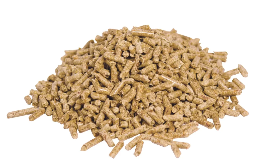
Small-scale biomass generators can utilize various types of biomass fuels for power generation. Here are some common fuel types used in small-scale biomass generators:
- Wood Chips: Wood chips are small pieces of wood obtained from forestry operations, sawmills, or wood processing facilities. They are a widely available and cost-effective fuel source for biomass generators.
- Wood Pellets: Wood pellets are compressed biomass fuel made from sawdust, wood shavings, or other wood residues. They have a standardized size and shape, which makes them convenient for storage and handling.
- Agricultural Residues: Biomass generators can also utilize agricultural residues such as straw, corn stalks, rice husks, and sugarcane bagasse. These residues are by-products of agricultural activities and can be used as fuel to generate power.
- Energy Crops: Certain crops, such as switchgrass and miscanthus, can be grown specifically for energy production. These energy crops have high biomass yields and can be used as a renewable fuel source for biomass generators.
- Forestry Residues: Forest residues, including branches, bark, and logging residues, can be used as fuel in biomass generators. These residues are typically obtained from forest management activities or timber harvesting operations.
- Biogas: Biogas, produced through anaerobic digestion of organic materials such as agricultural waste, food waste, or animal manure, can be used as a fuel in biomass generators. Biogas contains methane, which can be burned to generate heat and electricity.
The choice of fuel type depends on factors such as availability, cost, energy content, and environmental considerations. It’s important to ensure that the chosen fuel is compatible with the specific biomass generator and that proper fuel handling and storage measures are in place to ensure efficient and safe operation.
Combustion System
The combustion system in a small-scale biomass generator is responsible for converting the biomass fuel into heat energy through the process of combustion. The combustion system typically consists of the following components:
- Fuel Storage: Biomass fuel, such as wood chips or pellets, is stored in a designated storage area. The fuel should be stored in a dry and well-ventilated space to prevent moisture absorption and degradation.
- Fuel Feeding System: The fuel feeding system transports the biomass fuel from the storage area to the combustion chamber. This can be achieved through various mechanisms such as augers, conveyor belts, or pneumatic systems.
- Combustion Chamber: The combustion chamber is where the biomass fuel is burned. It is designed to facilitate efficient and controlled combustion. The combustion chamber is typically lined with refractory materials to withstand high temperatures and ensure optimal combustion conditions.
- Air Supply System: Air is required for the combustion process. The air supply system provides a controlled amount of air to the combustion chamber. It may include fans or blowers that deliver the required amount of oxygen for efficient combustion.
- Ignition System: The ignition system is responsible for initiating the combustion process. It can use various methods such as electric spark ignition or hot surfaces to ignite the biomass fuel.
- Combustion Control System: A combustion control system monitors and regulates the combustion process to ensure optimal performance and efficiency. It may include sensors, controllers, and actuators that adjust parameters such as fuel feed rate, air-to-fuel ratio, and temperature.
- Ash Removal System: During combustion, ash and other solid residues are generated. An ash removal system, such as an ash auger or a mechanical grate, is used to remove the ash from the combustion chamber to maintain proper combustion efficiency.
The combustion system plays a crucial role in achieving efficient and clean combustion of biomass fuel, thereby maximizing the heat energy output for power generation. Proper maintenance and regular cleaning of the combustion system are essential to ensure its reliable and safe operation.
Engine or Turbine
In small-scale biomass power generation systems, both engines and turbines can be used to convert the heat energy from biomass combustion into mechanical energy, which is then further converted into electrical energy. The choice between an engine and a turbine depends on various factors, including the specific requirements of the application, fuel type, efficiency considerations, and cost.
- Engine: Biomass combustion can be used to drive internal combustion engines, such as reciprocating engines or gas turbines. These engines work on the principle of converting the high-pressure and high-temperature gases produced by biomass combustion into linear or rotary motion. The motion is then used to drive a generator to produce electricity. Engines are typically used in smaller-scale applications and are known for their flexibility in utilizing a wide range of biomass fuels.
- Turbine: Biomass combustion can also be used to generate steam, which can be expanded through a steam turbine to produce mechanical energy. The high-pressure steam generated from biomass combustion is directed onto turbine blades, causing them to rotate. The rotational motion is then used to drive a generator to produce electricity. Turbines are commonly used in larger-scale biomass power plants where steam generation is more efficient and higher power outputs are required.
Both engines and turbines have their advantages and considerations:
- Engines are known for their quick startup and response time, making them suitable for applications with varying power demands. They can operate at high efficiencies and have the ability to utilize lower-quality biomass fuels. However, engines may require more maintenance and have higher emissions compared to turbines.
- Turbines, particularly steam turbines, offer higher efficiency in converting heat energy to mechanical energy. They can handle large-scale power generation and are well-suited for continuous operation. However, steam turbines may have a longer startup time and may require higher-quality biomass fuels and a more complex steam generation system.
The choice between an engine and a turbine for small-scale biomass power generation depends on factors such as power requirements, fuel availability, operational flexibility, efficiency goals, and budget considerations. It is important to conduct a feasibility study and assess the specific needs of the application to determine the most suitable technology.
Steam Turbine
A steam turbine is a device that converts the thermal energy of steam into mechanical energy, which can then be used to generate electricity or perform mechanical work. Steam turbines are widely used in power plants, industries, and marine applications.
Here’s a basic overview of how a steam turbine works:
- Steam Generation: Steam is generated by heating water. This can be achieved by burning fossil fuels (coal, natural gas, oil), using nuclear reactions, or harnessing renewable energy sources like solar or geothermal.
- Expansion of Steam: The high-pressure steam produced in the boiler is directed into the steam turbine. The steam enters the turbine at a high velocity and pressure.
- Blades and Rotors: The steam flows through a series of blades mounted on rotors. As the steam passes over these blades, it causes the rotor to spin. The spinning rotor is connected to a shaft.
- Mechanical Work: The kinetic energy of the rotating rotor is converted into mechanical work. This work can be used to turn an electrical generator, drive machinery, or perform other tasks.
- Exhaust: After passing through the turbine blades, the steam exits the turbine at a lower pressure and temperature. This low-pressure steam is then condensed back into water and returned to the boiler to be reheated and used again.
Steam Generation for a Steam Turbine
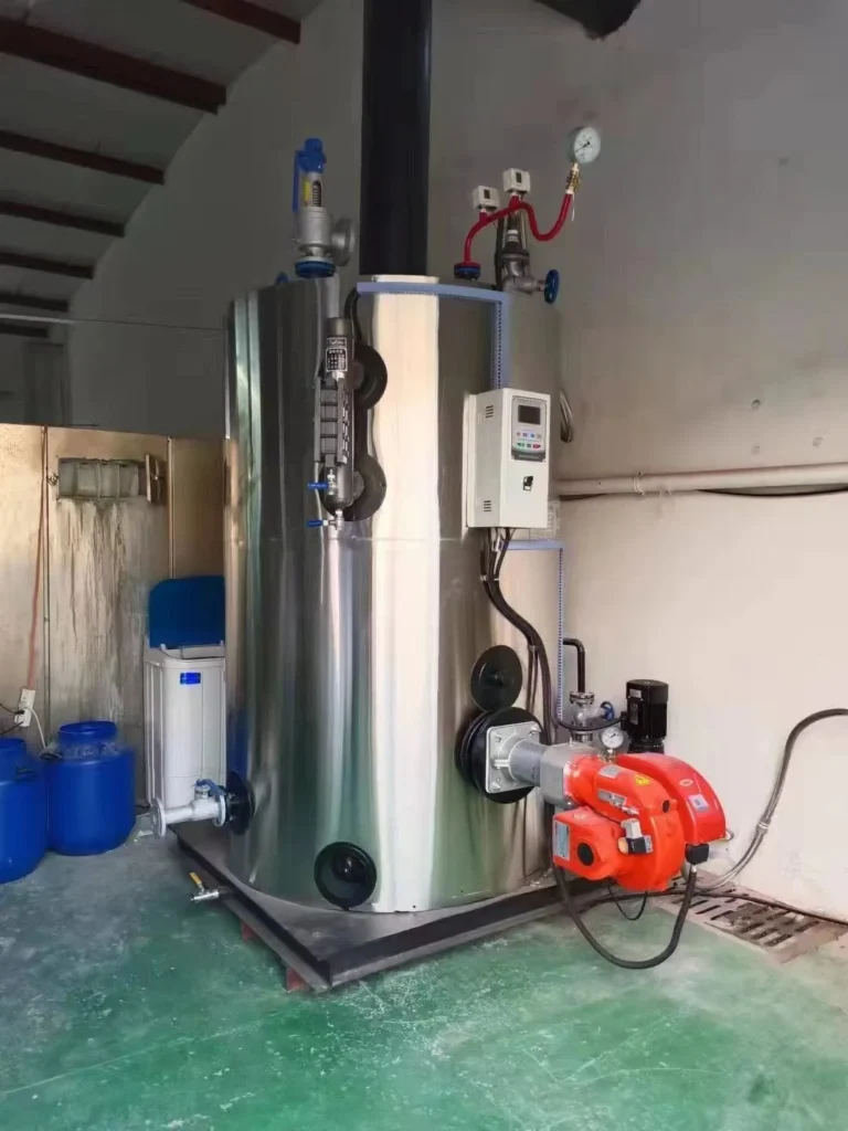
Steam generation is the process of producing steam from water. This steam can be used for various purposes, including power generation, heating, and industrial processes. The most common method of steam generation involves the use of a boiler, where water is heated to produce steam. Here is an overview of the steam generation process:
- Boiler: A boiler is a device that is designed to convert water into steam by applying heat energy to the water. The heat is usually generated by burning fuel, such as coal, natural gas, oil, or biomass, or by using electricity or renewable energy sources like solar or geothermal.
- Combustion or Heat Source: In fossil fuel-fired boilers, combustion occurs in a combustion chamber where the fuel is burned, releasing heat. The heat generated is transferred to the water in the boiler to raise its temperature.
- Water Feed: Water is fed into the boiler through a feedwater system. This can be a continuous process to maintain a steady supply of water to the boiler.
- Heat Transfer: The heat from the combustion process is transferred to the water in the boiler. This causes the water to reach a temperature at which it turns into steam.
- Steam Formation: As the water absorbs heat, it undergoes a phase change from liquid to vapor. The steam produced is then collected in the upper part of the boiler.
- Superheating (optional): In some cases, the steam is further heated to increase its temperature and energy content. This process is known as superheating and is done in a separate section of the boiler.
- Steam Distribution: Once the steam is generated, it can be distributed through pipelines for various applications. In power plants, the steam is often used to turn turbines connected to generators to produce electricity. In industrial processes, steam is utilized for heating, drying, and other manufacturing operations.
Boiler
A boiler is a closed vessel or apparatus designed to heat water or other fluids. It is an essential component in various industries, as it plays a key role in generating steam for power generation, heating systems, and industrial processes. The basic function of a boiler is to convert water into steam by applying heat energy to the water. Here are the key components and types of boilers:
Key Components of a Boiler:
- Burner: The burner is responsible for supplying the heat energy by burning fuel. Common fuels include natural gas, oil, coal, and biomass. The burner releases the heat into the combustion chamber.
- Combustion Chamber/Furnace: This is where the fuel is burned to release heat. The combustion chamber is designed to contain and control the combustion process.
- Heat Exchanger: The heat exchanger is a component that transfers heat from the combustion gases to the water, causing the water to convert into steam. Heat exchangers can be of various types, including fire-tube, water-tube, and coil-type designs.
- Water or Steam Drum: The drum serves as a reservoir for the water or steam. In water-tube boilers, multiple drums may be used to separate different stages of the steam generation process.
- Tubes or Coils: These are the pathways through which the hot gases or combustion products flow, transferring heat to the water. In fire-tube boilers, the tubes contain the water, while in water-tube boilers, the water flows through the tubes.
- Boiler Shell: The boiler shell is the outer cylindrical part that contains the pressure vessel and other components. It provides structural support and protection.
- Controls and Instrumentation: Boilers are equipped with various controls and instrumentation to monitor and regulate the combustion process, water level, pressure, and other parameters.
Types of Boilers:
- Fire-Tube Boilers: In these boilers, hot gases pass through tubes that are surrounded by water. The heat is transferred from the tubes to the water, producing steam. Fire-tube boilers are typically used for low to medium pressure applications.
- Water-Tube Boilers: In water-tube boilers, water flows through tubes, and combustion gases pass around these tubes. Water-tube boilers are often used in high-pressure applications and large industrial settings.
- Electric Boilers: These boilers use electricity to generate heat and are suitable for applications where other fuel sources may be impractical.
- Biomass Boilers: These boilers use organic materials, such as wood or agricultural residues, as fuel.
- Circulating Fluidized Bed (CFB) Boilers: CFB boilers use a fluidized bed of particles to efficiently burn solid fuels.
The choice of boiler type depends on factors such as the application, required steam pressure, and fuel availability. Boilers are critical components in providing heat and steam for a wide range of industrial and commercial processes, contributing significantly to energy production and various manufacturing operations.
Combustion or Heat Source
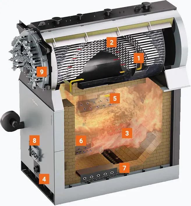
- 3-Pass boiler (6 bar – higher pressure ratings on request)
- Safety heat exchanger (integrated into boiler)
- Combustion chamber
- Blow-in ports
- Injection of secondary air
- Injection of flue gas recirculation
- Automatic ash removal from the combustion chamber using a water-cooled screw
- Firebox door
- Pneumatic boiler tube dedusting (optional)
The combustion or heat source in a boiler is a critical component responsible for generating the thermal energy needed to convert water into steam. The combustion process involves burning a fuel to release heat, and the choice of fuel depends on factors such as availability, cost, and environmental considerations. Common fuels used in boilers include:
- Natural Gas: A clean-burning fossil fuel that is widely used for heating and power generation. It produces fewer emissions compared to other fossil fuels.
- Oil (Diesel or Heavy Fuel Oil): Liquid fuels that are commonly used in boilers, especially in areas where natural gas availability is limited.
- Coal: A traditional and widely used fuel in boilers, especially in power plants. However, coal combustion releases higher levels of carbon dioxide and other pollutants compared to some other fuels.
- Biomass: Organic materials such as wood, crop residues, and animal waste can be used as biomass fuel in boilers. Biomass is considered renewable and can contribute to reduced greenhouse gas emissions.
- Electricity: Some boilers are electrically powered, using electricity as the heat source. This method is often used in areas where other fuel sources are impractical or expensive.
- Renewable Energy Sources: In some cases, boilers can be designed to use renewable energy sources like solar or geothermal energy to generate heat.
The combustion process typically takes place in a combustion chamber or furnace within the boiler. The key steps in combustion include:
- Fuel Combustion: The fuel is introduced into the combustion chamber, where it reacts with oxygen from the air. This chemical reaction releases heat energy.
- Flame Formation: The heat generated from the combustion reaction results in the formation of a flame. The flame is responsible for heating the surfaces of the boiler, including the heat exchanger or tubes.
- Transfer of Heat: The heat from the combustion process is transferred to the water or other fluid in the boiler. This transfer of heat causes the water to reach its boiling point, leading to the production of steam.
- Control of Combustion: To ensure efficient and safe operation, combustion in boilers is carefully controlled. This involves monitoring factors such as fuel-air ratio, temperature, and pressure to optimize combustion efficiency and minimize emissions.
Efficient combustion is crucial for the overall performance of a boiler system. Modern boilers often incorporate advanced control systems to regulate the combustion process, ensuring optimal efficiency, minimal environmental impact, and safe operation.
Water Feed
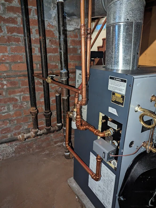
The water feed system in a boiler is a crucial component that manages the supply of water to the boiler for steam generation. This system ensures a continuous and controlled supply of water to the boiler, maintaining the desired water level. Proper water feed is essential for efficient and safe boiler operation. Here’s how the water feed system typically works:
- Water Source: The water feed system starts with a source of water, which can come from various places depending on the application. It might be from a city water supply, a well, or another water source.
- Make-up Water: In many boiler systems, a portion of the water is continuously removed from the system as steam is generated, and this water needs to be replaced. The replacement water is often referred to as make-up water.
- Feedwater Pump: The water feed system includes a pump, known as the feedwater pump, which is responsible for delivering the make-up water to the boiler. The pump ensures a consistent flow of water into the boiler.
- Feedwater Control Valve: A control valve is often installed to regulate the flow of water into the boiler. This valve is typically controlled by a level sensor or controller that monitors the water level inside the boiler. The valve opens or closes to adjust the flow of water and maintain the desired water level.
- Preheating (Optional): In some boiler systems, make-up water may be preheated before entering the boiler. Preheating the water can improve energy efficiency by utilizing waste heat from the flue gases or other sources.
- Water Treatment: Depending on the quality of the water source, water treatment processes may be employed to remove impurities and prevent scale or corrosion inside the boiler. This is important for the longevity and efficient operation of the boiler.
- Expansion Tank (Optional): In closed-loop systems, an expansion tank may be used to accommodate changes in water volume due to temperature variations. This helps maintain a stable pressure in the system.
The water feed system is designed to maintain the proper water level inside the boiler. If the water level is too low, it can expose the boiler tubes or heating surfaces to excessive heat, leading to potential damage. On the other hand, if the water level is too high, it can result in carryover of water into the steam, which can cause operational issues and reduce the efficiency of the system.
Proper water feed control is essential for the safe and efficient operation of boilers, and it is often automated using control systems to ensure precise and continuous regulation of water flow. Regular maintenance and monitoring of the water feed system are important aspects of boiler management.
Heat Transfer
Heat transfer is the process by which thermal energy is exchanged between different regions of a system or between different systems. There are three primary methods of heat transfer: conduction, convection, and radiation.
- Conduction:
- Definition: Conduction is the transfer of heat through a material without any movement of the material itself. It occurs when neighboring atoms or molecules transfer kinetic energy to each other.
- Example: When one end of a metal rod is heated, the heat energy is conducted through the material, and the other end of the rod becomes warm.
- Convection:
- Definition: Convection involves the transfer of heat through the movement of fluids (liquids or gases). It occurs due to the circulation of the fluid caused by temperature differences.
- Example: Heating water in a pot on a stove causes hot water to rise, creating a circulation pattern. As the hot water rises, cooler water moves down to replace it, resulting in a continuous flow of heat.
- Radiation:
- Definition: Radiation is the transfer of heat through electromagnetic waves, such as infrared radiation. Unlike conduction and convection, radiation does not require a medium and can occur in a vacuum.
- Example: The heat from the Sun reaches the Earth through radiation. Similarly, a heated electric coil radiates heat in an electric stove.
The effectiveness of each heat transfer method depends on the specific conditions and materials involved. In many real-world situations, multiple methods may occur simultaneously.
Applications:
- Cooking: Heat transfer is crucial in cooking processes. For example, conduction occurs when a pan is heated on a stove, convection occurs in the boiling of water, and radiation is involved in grilling or roasting.
- Engineering: Heat transfer is fundamental in various engineering applications, such as designing efficient heat exchangers, cooling systems for electronics, and insulation materials.
- Climate Control: HVAC systems use heat transfer principles to cool or heat buildings. For instance, air conditioning systems use a combination of conduction, convection, and sometimes radiation to remove heat from indoor spaces.
- Power Generation: In power plants, heat transfer is integral to the conversion of thermal energy into mechanical energy and then into electricity. Steam turbines, for example, rely on heat transfer to generate power.
Understanding and controlling heat transfer processes are essential for designing efficient systems, improving energy efficiency, and preventing undesired effects such as overheating or heat loss.
Steam Formation
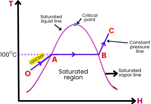
Steam formation is a phase-change process in which water is converted from its liquid state to a gaseous state, which we commonly refer to as steam. This process occurs when water absorbs enough heat energy to overcome the latent heat of vaporization. Here’s a general overview of steam formation:
- Application of Heat:
- Steam formation begins with the application of heat to water. The heat can come from various sources, such as burning fossil fuels, nuclear reactions, or renewable energy sources like solar or geothermal.
- Temperature Increase:
- As heat is applied, the temperature of the water rises. At normal atmospheric pressure, water boils at 100 degrees Celsius (212 degrees Fahrenheit). However, the boiling point increases with pressure.
- Boiling:
- Once the water temperature reaches its boiling point at a given pressure, further application of heat does not cause a temperature increase. Instead, the absorbed heat is used to convert the water into steam.
- Phase Change:
- The phase change from liquid to gas involves the absorption of latent heat of vaporization. This is the energy required to break the bonds between water molecules and convert them from a liquid to a gaseous state without a change in temperature.
- Steam Generation:
- The resulting vapor is steam, which is composed of water vapor molecules. Steam is characterized by high energy content and the ability to do work, making it a valuable resource for various applications.
- Expansion (Optional):
- In some systems, steam can be further expanded or superheated, meaning its temperature is increased beyond the boiling point. This can enhance its energy content and specific properties.
The process of steam formation is a critical aspect of power generation in steam turbines. In power plants, water is heated in a boiler, and the resulting steam is directed onto turbine blades. The expansion of steam in the turbine generates mechanical energy, which is then used to turn generators and produce electricity.
It’s important to note that the conditions under which steam formation occurs, such as pressure and temperature, can influence the properties of the steam and its applications. Additionally, proper control and maintenance of steam generation systems are essential for efficient and safe operation.
Superheating
Superheating is a process in which steam is heated beyond its saturation point, which is the temperature at which it would normally boil at a given pressure. In other words, superheated steam is steam that has been further heated after reaching the boiling point and being completely vaporized.
The key characteristics of superheated steam include:
- Temperature Increase: Superheated steam is at a higher temperature than the saturation temperature corresponding to its pressure. The temperature of superheated steam is often measured in degrees Celsius or Fahrenheit.
- No Saturation: Unlike saturated steam, which is at the boiling point for a given pressure and contains both liquid and vapor phases, superheated steam consists entirely of vapor.
- Increased Energy Content: Superheated steam carries more energy per unit mass than saturated steam at the same pressure and volume. This makes it useful for certain industrial processes and enhances its ability to do work.
The process of superheating steam is typically achieved in a separate section of a boiler or a dedicated superheater. Here’s how it generally works:
- Boiling Water: The initial step involves boiling water to produce saturated steam in a boiler.
- Separation: The saturated steam is then separated from any remaining water droplets, ensuring that it is in a clean, vapor state.
- Superheating Section: The steam is then passed through a superheater, which is a heat exchanger designed to add more heat to the steam. This raises the temperature of the steam without changing its pressure.
- Controlled Temperature: The temperature of the steam leaving the superheater can be controlled to achieve the desired level of superheat.
Superheated steam finds application in various industrial processes and power generation for several reasons:
- Increased Efficiency: Superheated steam can enhance the efficiency of certain processes, particularly in power plants, where it is used to drive turbines more effectively.
- Prevention of Condensation: Superheating helps prevent condensation in steam pipes, ensuring that the steam remains dry and does not lose energy through the formation of water droplets.
- Improved Heat Transfer: Superheated steam can be advantageous in certain heat transfer applications where a high-temperature heat source is required.
It’s important to note that the design and use of superheaters depend on the specific requirements of the industrial or power generation process, and considerations such as safety and system efficiency play crucial roles in their implementation.
Steam Distribution
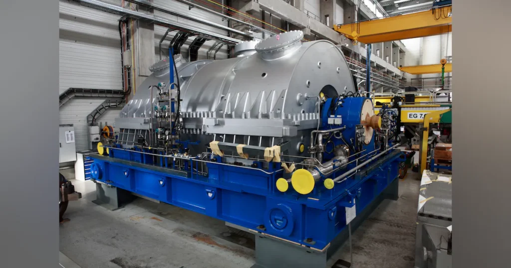
Steam distribution involves the transportation and delivery of steam from the point of generation (such as a boiler) to the points of use, where it can be utilized for various industrial, commercial, or residential applications. The efficiency and safety of steam distribution systems are essential for the successful operation of processes that rely on steam. Here are key aspects of steam distribution:
- Piping System:
- Steam is transported through a network of pipes from the boiler to the various points of use. The piping system must be designed to handle the high temperatures and pressures associated with steam, and it should be insulated to minimize heat loss.
- Valves and Controls:
- Valves are used to control the flow of steam within the distribution system. Control valves and other devices regulate the pressure, temperature, and flow rate of steam at different points to meet the specific requirements of the processes or equipment being served.
- Steam Traps:
- Steam traps are devices installed in the steam distribution system to remove condensate (liquid water) that forms as steam cools during transportation. Proper condensate removal is crucial for maintaining the efficiency of the system and preventing damage to equipment.
- Pressure Reducing Stations:
- Pressure reducing stations are often employed in steam distribution systems to reduce the pressure of high-pressure steam to a level suitable for specific applications. These stations typically include pressure-reducing valves.
- Safety Devices:
- Various safety devices, such as pressure relief valves, are installed to protect the steam distribution system and equipment from overpressure situations. These devices help ensure the safety of personnel and prevent damage to the system.
- Steam Meters:
- Steam meters are used to measure the amount of steam consumed at different points in the distribution system. This information is crucial for monitoring energy usage, optimizing system performance, and managing costs.
- Condensate Return System:
- Condensate, which forms when steam loses heat energy, is returned to the boiler through a condensate return system. This allows the reuse of the water and reduces the need for additional water makeup.
- Insulation:
- Proper insulation of steam pipes is essential to minimize heat loss and maintain the temperature of steam during transportation. Insulation materials include fiberglass, foam, or other materials suitable for high-temperature applications.
- Steam Distribution in Power Plants:
- In power plants, steam is distributed from the boiler to the turbines, where it is used to generate mechanical power. The high-pressure steam is then condensed back to water and returned to the boiler.
Effective steam distribution is crucial for optimizing energy efficiency, reducing operational costs, and ensuring the reliability of processes that rely on steam. Regular maintenance, monitoring, and adherence to safety standards are essential for the safe and efficient operation of steam distribution systems.
Expansion of Steam
The expansion of steam refers to the process where steam undergoes an increase in volume as it moves from a higher pressure to a lower pressure. This expansion is a crucial part of many steam-based systems, particularly in power generation.
Here’s how the expansion of steam typically occurs in the context of a steam turbine in a power plant:
- High-Pressure Steam:
- Steam is generated in a boiler at high pressure and temperature. This high-pressure steam is directed towards the blades of a steam turbine.
- Turbine Blades:
- As the high-pressure steam flows over the blades of the turbine, it imparts its high kinetic energy to the blades, causing them to spin.
- Mechanical Work:
- The spinning turbine blades are connected to a shaft, and as the blades turn, they perform mechanical work on the shaft. This mechanical work is transferred to a generator, where it is converted into electrical energy.
- Expansion:
- As the steam passes through the turbine blades, it undergoes a significant expansion. The pressure and temperature of the steam decrease, and its volume increases. This is due to the conversion of the steam’s energy into mechanical work.
- Low-Pressure Steam:
- The steam exiting the turbine is now at a lower pressure and temperature. In some cases, this low-pressure steam may be directed to additional turbine stages to extract more work from the steam.
- Condensation (Optional):
- In certain power generation cycles, the low-pressure steam may be condensed back into water, and the water is then returned to the boiler to begin the process again.
The expansion of steam in a turbine is a key step in converting thermal energy into mechanical energy, which is then further transformed into electrical energy. The efficiency of this process is influenced by factors such as the design of the turbine, the pressure and temperature of the steam, and the overall design of the power plant.
It’s worth noting that the expansion of steam can also occur in other applications beyond power generation, such as in industrial processes where steam is used for mechanical work or heating. Understanding and controlling the expansion process are critical for optimizing the performance and efficiency of steam-based systems.
High-Pressure Steam
High-pressure steam refers to steam that is generated at a pressure significantly above atmospheric pressure. The specific pressure considered “high” can vary depending on the context, but in the realm of power generation and industrial processes, high-pressure steam is typically generated at pressures exceeding 15 psi (pounds per square inch) or 1.03 bar.
Here are key characteristics and applications of high-pressure steam:
- Generation in Boilers:
- High-pressure steam is often generated in specialized boilers designed to handle the higher pressures. These boilers can be found in power plants, industrial facilities, and other settings where the high-energy content of steam is required for various applications.
- Power Generation:
- In power plants, high-pressure steam is crucial for driving steam turbines. The expansion of high-pressure steam in turbines is used to generate mechanical work, which is then converted into electricity by generators.
- Industrial Processes:
- High-pressure steam is widely used in various industrial processes. Industries such as chemical, petrochemical, and manufacturing utilize high-pressure steam for tasks like sterilization, heating, and powering equipment.
- Heat Transfer:
- High-pressure steam is an effective medium for heat transfer due to its high energy content. It is used in heat exchangers, where it can transfer thermal energy to fluids or surfaces.
- Cogeneration (Combined Heat and Power):
- High-pressure steam is often employed in cogeneration systems where both electricity and useful heat are generated from the same energy source. The high-temperature steam can be used for industrial processes, and the remaining thermal energy can be converted into electricity.
- District Heating:
- In some district heating systems, high-pressure steam is used to distribute heat for residential and commercial heating applications.
- Quality and Safety Considerations:
- The quality and safety of high-pressure steam are crucial considerations. Steam at higher pressures and temperatures can cause more severe burns and injuries, and proper safety measures, including pressure relief devices, are essential.
- Boiler Design:
- Boilers designed for high-pressure steam must meet stringent safety and engineering standards. The construction and materials used in high-pressure boilers are carefully selected to withstand the elevated pressures and temperatures.
The selection of high-pressure steam is often driven by the specific requirements of the application. For instance, processes that demand high temperatures or high energy density may benefit from the use of high-pressure steam. However, it’s important to design and operate systems handling high-pressure steam with great care to ensure safety and efficiency. Regular maintenance, monitoring, and adherence to safety guidelines are critical aspects of managing high-pressure steam systems.
Turbine Blades
Turbine blades are a crucial component in steam turbines, gas turbines, and some types of water turbines. These blades play a key role in converting the kinetic energy of a moving fluid (steam, gas, or water) into mechanical energy that can be used to drive a generator or perform other types of work. Here’s an overview of turbine blades and their functions:
- Function:
- The primary function of turbine blades is to extract energy from a high-velocity fluid (steam or gas) and convert it into rotational mechanical energy. This rotational energy is then used to drive a generator or other machinery.
- Types of Turbine Blades:
- There are different types of turbine blades based on the specific requirements and design of the turbine. Two common types are:
- Impulse Blades: These blades operate on the principle of impulse. The high-velocity fluid (steam or gas) impacts the blades, causing them to rotate.
- Reaction Blades: These blades operate on the principle of both impulse and reaction. The fluid expands as it passes through the blades, causing both an impulse and a reaction force that drives the turbine.
- There are different types of turbine blades based on the specific requirements and design of the turbine. Two common types are:
- Material and Design:
- Turbine blades are typically made from high-strength materials that can withstand high temperatures and mechanical stresses. Common materials include high-alloy steels, superalloys, and advanced materials like ceramics and composites. The design of the blades is aerodynamically optimized to maximize efficiency and minimize losses.
- Cooling Systems:
- In gas turbines and certain steam turbines, where temperatures can reach extremely high levels, cooling systems are often integrated into the turbine blades. These systems help prevent overheating and maintain the structural integrity of the blades.
- Blade Profiles:
- Turbine blades have specific aerodynamic profiles designed to efficiently extract energy from the fluid. The shape of the blade is critical in maximizing the conversion of kinetic energy into mechanical energy.
- Arrangement:
- Turbine blades are arranged in rows, with each row designed to extract additional energy from the fluid. The arrangement may include multiple stages, each consisting of a set of rotating blades (rotor) and a set of stationary blades (stator).
- Manufacturing Processes:
- Turbine blades are often manufactured using precision casting or machining techniques to achieve the required shapes and tolerances. The manufacturing process is crucial to maintaining the aerodynamic efficiency of the blades.
- Maintenance:
- Turbine blades undergo significant stresses during operation, and proper maintenance is essential to ensure their performance and longevity. Regular inspections, repairs, and, if necessary, replacements are part of turbine maintenance procedures.
Turbine blades are critical components in power generation, aviation, and industrial applications. The efficiency and performance of turbines depend significantly on the design, material, and condition of the blades. Advances in materials and manufacturing technologies continue to improve the efficiency and reliability of turbine blades in various applications.
Mechanical Work
The mechanical work of a steam turbine is a result of the conversion of thermal energy in the form of high-pressure, high-temperature steam into mechanical energy, which is then used to drive a generator or perform other types of mechanical work. Here’s an overview of how a steam turbine generates mechanical work:
- Steam Generation:
- Steam is generated in a boiler by heating water. The heat source can be various, including burning fossil fuels (coal, natural gas, oil), using nuclear reactions, or harnessing renewable energy sources.
- High-Pressure Steam:
- The steam produced in the boiler is at high pressure and temperature. This high-pressure steam carries a significant amount of thermal energy.
- Expansion in the Turbine:
- The high-pressure steam is directed into the steam turbine. As the steam flows through the turbine blades, it undergoes a process of expansion. This expansion is a key aspect of the conversion of thermal energy into mechanical energy.
- Turbine Blades:
- The expansion of steam causes the turbine blades to rotate. There are two main types of steam turbines based on the principles of operation: impulse turbines and reaction turbines. In impulse turbines, the high-velocity steam impacts the blades, causing them to rotate. In reaction turbines, both the velocity and pressure of the steam change as it passes through the blades, generating rotational motion.
- Rotation of the Turbine Shaft:
- The rotating turbine blades are connected to a shaft. As the blades turn, they impart rotational motion to the shaft.
- Generator Connection:
- The shaft of the turbine is connected to a generator. The mechanical rotation of the shaft is used to turn the generator rotor within a magnetic field, inducing an electric current in the generator windings.
- Generation of Electricity:
- The electric current generated in the generator is then transmitted through the power grid for use in homes, industries, or other applications.
- Exhaust and Condensation:
- After passing through the turbine, the steam is at a lower pressure and temperature. In many power plants, the steam is then directed to a condenser, where it is condensed back into water. The condensed water is returned to the boiler to be reheated and reused in the steam cycle.
The overall efficiency of a steam turbine system depends on various factors, including the design of the turbine, the quality of steam, and the control systems in place. Improvements in turbine design, materials, and control technology have led to more efficient and reliable steam turbines in power generation and industrial applications.
Expansion
Expansion, in a thermodynamic context, refers to the process by which a substance undergoes a change in volume as a result of an increase in temperature or a decrease in pressure. Expansion can occur in various states of matter, including gases, liquids, and solids. Here, I’ll briefly explain expansion in the context of gases and liquids:
- Gas Expansion:
- In gases, expansion is a response to an increase in temperature or a decrease in pressure. When a gas is heated, its molecules gain kinetic energy and move more rapidly, leading to an increase in pressure and volume. The relationship between pressure, volume, and temperature in a gas is described by the ideal gas law (PV = nRT), where P is pressure, V is volume, n is the number of moles of gas, R is the gas constant, and T is temperature.
- For example, if you have a gas confined in a container and you heat it, the pressure inside the container will increase, and the gas will expand to occupy a larger volume.
- Liquid Expansion:
- In liquids, expansion primarily occurs due to an increase in temperature. When a liquid is heated, its molecules gain energy, causing them to move more vigorously and increasing the average separation between molecules. This results in an increase in the volume of the liquid.
- An everyday example of liquid expansion is the expansion of water when heated. When you heat water, it expands and can lead to the rising of liquid levels in containers.
- Thermal Expansion in Solids:
- In solids, expansion occurs when the material is heated. This is known as thermal expansion. When a solid is heated, its molecules vibrate more rapidly, causing the material to expand. Different materials have different coefficients of thermal expansion, which describe how much they expand or contract for a given change in temperature.
- The expansion and contraction of materials due to temperature changes are critical considerations in construction, engineering, and the design of structures and components.
Expansion has practical implications in various fields, and it’s important to account for these changes in real-world applications. For instance, in the design of bridges, buildings, and pipelines, engineers need to consider the potential expansion and contraction of materials due to temperature variations to prevent structural damage or failure. Similarly, the study of gas expansion is fundamental to the understanding of thermodynamics and the operation of heat engines, including steam turbines and internal combustion engines.
Low-Pressure Steam
Low-pressure steam refers to steam that is generated or used at a pressure lower than atmospheric pressure. In the context of steam, pressure is a crucial parameter that affects the temperature, density, and energy content of the steam. Low-pressure steam is often employed in various industrial, commercial, and residential applications where lower temperature and pressure conditions are suitable. Here are some key points about low-pressure steam:
- Pressure Range:
- While there is no strict definition for “low-pressure” steam, it generally refers to steam generated at pressures below 15 pounds per square inch (psi) or 1.03 bar. However, the specific pressure range can vary depending on the application and industry.
- Applications:
- Low-pressure steam has a wide range of applications, including but not limited to:
- Heating Systems: Low-pressure steam is used in heating systems for space heating in buildings, particularly in older systems where steam boilers are employed.
- Industrial Processes: Certain industrial processes require steam for heating, humidification, or specific manufacturing operations. Low-pressure steam can be suitable for these applications.
- Food Processing: In food processing, low-pressure steam is often used for tasks like sterilization, cooking, and maintaining controlled temperatures.
- Low-pressure steam has a wide range of applications, including but not limited to:
- Temperature and Energy Content:
- Steam pressure is directly related to its temperature and energy content. Low-pressure steam will have a lower temperature compared to high-pressure steam. While it may not carry as much energy per unit volume, it can still provide sufficient heat for many applications.
- Boiler Design:
- Boilers designed to produce low-pressure steam may have different specifications and safety features compared to high-pressure boilers. The design considerations include maintaining the required temperature and pressure for the intended application.
- Safety Considerations:
- While the safety risks associated with low-pressure steam are generally lower than those with high-pressure steam, proper safety measures, including pressure relief devices and regular maintenance, are still essential to prevent accidents and ensure safe operation.
- Condensate Handling:
- Low-pressure steam systems often deal with condensate, which is the liquid water formed as steam gives up its latent heat. Proper handling of condensate is important for system efficiency and preventing water hammer.
- Energy Efficiency:
- The use of low-pressure steam in certain applications can contribute to energy efficiency, especially when the lower pressure meets the requirements of the process. It is essential to match the steam characteristics to the needs of the specific application.
Understanding the requirements and characteristics of the application is crucial when determining whether low-pressure steam is suitable. It is commonly used in systems where the energy requirements and safety considerations align with the characteristics of low-pressure steam.
Condensation
Condensation is the process by which a substance changes its physical state from a gas or vapor to a liquid. This phase transition occurs when the temperature of the substance decreases to the point where its vapor pressure equals the atmospheric pressure. Condensation is a common natural phenomenon with widespread applications in various fields. Here are key aspects of condensation:
- Temperature Reduction:
- Condensation occurs when a gas or vapor is cooled. As the temperature of the substance decreases, its molecular movement slows down, and the molecules come together to form a liquid.
- Vapor Pressure:
- The transition from a gas to a liquid during condensation is influenced by vapor pressure. Vapor pressure is the pressure exerted by a vapor when it is in equilibrium with its liquid phase. When the vapor pressure equals the atmospheric pressure, condensation occurs.
- Atmospheric Conditions:
- Atmospheric pressure plays a significant role in condensation. As the temperature drops, the atmospheric pressure remains relatively constant. When the vapor pressure of a substance matches the atmospheric pressure, condensation begins.
- Dew Point:
- The temperature at which air becomes saturated with moisture and dew or frost begins to form is known as the dew point. It represents the point at which condensation occurs in the atmosphere.
- Formation of Dew:
- Dew forms when moist air comes into contact with a surface that is colder than the air. The moisture in the air condenses on the cooler surface, forming water droplets.
- Formation of Clouds:
- In the atmosphere, condensation is a fundamental process in cloud formation. When warm, moist air rises and encounters cooler air at higher altitudes, the water vapor in the warm air condenses to form visible water droplets, leading to the creation of clouds.
- Condensation in Industrial Processes:
- Condensation is utilized in various industrial processes. For example, in refrigeration and air conditioning systems, a gas is compressed and then allowed to expand, leading to cooling and condensation of the refrigerant.
- Applications in Heat Exchangers:
- Condensation is used in heat exchangers to transfer heat from a vapor to a liquid state. This process is common in power plants, industrial processes, and HVAC systems.
- Reverse Process:
- The reverse of condensation is evaporation, where a liquid changes to a gas or vapor as it absorbs heat.
- Prevention of Condensation:
- Condensation can be managed by controlling temperature, humidity levels, and using insulation to prevent surfaces from becoming cooler than the dew point.
Understanding and controlling condensation are important in various contexts, from weather patterns and climate science to industrial processes and the design of HVAC systems. Managing condensation is crucial for preventing issues such as water damage, corrosion, and the formation of ice in different applications.
Blades and Rotors
In the context of a steam turbine, blades and rotors are integral components that play a crucial role in the conversion of thermal energy from steam into mechanical energy. Here’s an overview of the blades and rotors in a steam turbine:
Blades
- Turbine Blades:
- Function: Turbine blades are the primary components responsible for extracting energy from high-pressure, high-temperature steam and converting it into mechanical energy.
- Types:
- Impulse Blades: Convert the kinetic energy of high-velocity steam into mechanical energy through the impact of the steam on the blades.
- Reaction Blades: Operate on the principles of impulse and reaction, with steam expanding as it passes through the blades, generating both kinetic and pressure-driven forces.
- Blade Profiles:
- Turbine blades are designed with specific aerodynamic profiles to efficiently utilize the energy of the steam flow. The shape of the blades is critical for maximizing energy extraction and minimizing losses.
- Materials:
- Blades are typically made from high-strength materials capable of withstanding high temperatures and mechanical stresses. Superalloys, high-alloy steels, and advanced materials are commonly used.
- Cooling Systems:
- In some steam turbines, especially those in power plants where high temperatures are encountered, turbine blades may incorporate cooling systems to prevent overheating and maintain structural integrity.
Rotors
- Turbine Rotor:
- Function: The rotor is the rotating component of the steam turbine to which the turbine blades are attached. It is responsible for converting the rotational motion of the blades into mechanical work.
- Connection to Shaft: The rotor is connected to the shaft of the turbine. As the turbine blades rotate due to the impact of steam, the rotor, in turn, rotates, transferring mechanical energy to the shaft.
- Rotor Design:
- The design of the rotor is critical for the overall efficiency and performance of the steam turbine. It must be capable of withstanding the mechanical stresses induced by the rotation of the blades and the high-speed steam flow.
- Bearings and Seals:
- The rotor is supported by bearings that allow it to rotate smoothly. Seals are also employed to minimize steam leakage and maintain the efficiency of the turbine.
- Balancing:
- Proper balancing of the rotor is essential to prevent vibration and ensure the reliable and stable operation of the steam turbine. Unbalanced rotors can lead to mechanical issues and reduced efficiency.
- Materials:
- Rotor materials must possess high strength and fatigue resistance. The choice of materials depends on factors such as the turbine’s operating conditions and the design specifications.
The combination of turbine blades and rotor forms the core of a steam turbine, where the conversion of thermal energy to mechanical work takes place. This mechanical work is then used to drive a generator, producing electricity in power plants or performing other types of mechanical work in various industrial applications. The efficiency and reliability of the steam turbine depend significantly on the design, materials, and proper maintenance of these critical components.
Turbine Blades
Turbine blades are crucial components in turbines, which are devices that convert the energy of a moving fluid (such as steam, gas, or water) into mechanical energy. Turbines are widely used in various applications, including power generation, aviation, and industrial processes. Turbine blades play a central role in this energy conversion process. Here are key aspects of turbine blades:
Function
- Energy Extraction:
- Turbine blades are designed to extract energy from a high-velocity fluid (steam or gas) or from the kinetic energy of flowing water. The energy extraction results in the rotation of the turbine blades.
- Mechanical Work:
- As the turbine blades rotate, they perform mechanical work. This rotational motion can be used to drive a generator, produce electricity, or perform other types of mechanical work in industrial processes.
- Types of Turbines:
- Turbine blades are adapted to different types of turbines:
- Steam Turbines: Blades in steam turbines extract energy from high-pressure, high-temperature steam.
- Gas Turbines: Blades in gas turbines operate with high-velocity gases produced by combustion.
- Hydraulic Turbines: Blades in hydraulic turbines extract energy from flowing water.
- Turbine blades are adapted to different types of turbines:
Characteristics
- Aerodynamic Design:
- Turbine blades have specific aerodynamic profiles designed to efficiently capture the energy of the fluid. The shape of the blades is critical for maximizing energy extraction and minimizing losses.
- Materials:
- Turbine blades are typically made from materials that can withstand high temperatures, mechanical stresses, and corrosion. Common materials include high-alloy steels, superalloys, and advanced materials like ceramics and composites.
- Cooling Systems:
- In applications where temperatures are extremely high, such as in gas turbines or certain sections of steam turbines, turbine blades may incorporate cooling systems to prevent overheating and maintain structural integrity.
- Roots and Mounting:
- The root of the turbine blade is the part that attaches to the rotor. The mounting of blades on the rotor must be robust to withstand the mechanical forces during rotation.
Types of Turbine Blades
- Impulse Blades:
- Impulse blades operate on the principle of converting the kinetic energy of a high-velocity fluid into mechanical energy through the impact of the fluid on the blades. These blades are common in impulse turbines.
- Reaction Blades:
- Reaction blades operate on the principles of both impulse and reaction. The fluid expands as it passes through the blades, generating both kinetic and pressure-driven forces. Reaction blades are often used in reaction turbines.
Maintenance
- Balancing:
- Proper balancing of turbine blades is essential to prevent vibration and ensure the reliable and stable operation of the turbine.
- Inspections and Repairs:
- Regular inspections and, if necessary, repairs or replacements of turbine blades are crucial for maintaining efficiency and preventing unexpected failures.
Turbine blades represent a critical aspect of energy conversion systems and are designed with precision to maximize efficiency and reliability in various applications. Advances in materials and design continue to improve the performance of turbine blades in modern turbines.
Blade Profile
The blade profile, also known as the airfoil profile or blade shape, refers to the cross-sectional shape of a turbine or aircraft blade as seen from the direction of fluid flow (such as air or steam). The design of the blade profile is crucial for optimizing the aerodynamic performance of the blade and, consequently, the efficiency of the entire system. Here are key aspects of blade profiles:
Characteristics
- Aerodynamic Efficiency:
- The primary goal of designing a specific blade profile is to achieve high aerodynamic efficiency. This involves minimizing drag, maximizing lift, and ensuring smooth airflow over the blade surface.
- Lift and Drag:
- The shape of the blade profile determines its ability to generate lift, which is essential for extracting energy in turbines or providing lift in aircraft. The profile is also designed to minimize drag, as excessive drag can reduce efficiency.
- Angle of Attack:
- The angle of attack is the angle between the chord line (a straight line connecting the leading and trailing edges of the blade) and the direction of the fluid flow. The blade profile is carefully designed to optimize the angle of attack for different operating conditions.
- Chord Length:
- The chord length is the distance from the leading edge to the trailing edge along the chord line. Blade profiles are characterized by their chord length and shape, which influence the overall performance of the blade.
Common Blade Profiles
- NACA Airfoil Profiles:
- The National Advisory Committee for Aeronautics (NACA) developed a series of airfoil profiles with systematic numbering. NACA airfoils are widely used in aviation and turbomachinery applications.
- Symmetric and Asymmetric Profiles:
- Some blade profiles are symmetric, meaning the upper and lower surfaces are identical. Others are asymmetric, with different shapes on the upper and lower surfaces. Asymmetric profiles are often used for specific aerodynamic requirements.
- Cambered Profiles:
- Camber is the curvature of the blade’s upper and lower surfaces. Cambered profiles are designed with a curve to generate lift even at zero angle of attack, enhancing overall performance.
- Twisted Profiles:
- In certain applications, such as aircraft propellers, blade profiles may be twisted along their length to optimize performance across different sections of the blade.
Applications
- Aircraft Wings:
- Aircraft wings use specific airfoil profiles to achieve lift and control. The design of the wing profiles is crucial for the aerodynamic performance of the aircraft.
- Turbine Blades:
- Turbine blades in steam turbines, gas turbines, or wind turbines use carefully designed profiles to efficiently extract energy from the fluid (steam, gas, or wind).
- Propeller Blades:
- Propeller blades in marine applications or aircraft propulsion systems use specialized profiles to generate thrust efficiently.
- Fan Blades:
- Fan blades in HVAC systems or industrial fans use specific profiles for optimal airflow and energy efficiency.
Computational Fluid Dynamics (CFD)
- Simulation and Analysis:
- Advances in Computational Fluid Dynamics (CFD) allow engineers to simulate and analyze the performance of different blade profiles under various conditions before physical prototypes are built.
The selection of a specific blade profile depends on the application, operating conditions, and desired performance characteristics. Engineers use sophisticated design and analysis tools to optimize blade profiles for specific purposes, ensuring efficiency and reliability in diverse applications.
Materials
The materials used to manufacture turbine blades are carefully chosen to withstand the harsh conditions of high temperatures, pressures, and mechanical stresses encountered in turbine applications. Different types of turbines, such as steam turbines, gas turbines, and wind turbines, may require specific materials based on their operating environments. Here are common materials used for turbine blades:
1. Superalloys
- Applications: Gas Turbines, Steam Turbines
- Properties:
- High-temperature strength and creep resistance.
- Excellent corrosion resistance.
- Often contain nickel, cobalt, and other alloying elements.
- Able to withstand extreme temperature differentials.
2. Single-Crystal Alloys
- Applications: Gas Turbines, Aircraft Engines
- Properties:
- Uniform crystal structure provides superior high-temperature strength.
- Enhanced resistance to thermal fatigue.
- Used in the hottest sections of turbines.
3. Ceramic Matrix Composites (CMCs)
- Applications: Gas Turbines, High-Temperature Environments
- Properties:
- Excellent thermal and chemical stability.
- High strength at elevated temperatures.
- Lighter weight compared to metal alloys.
- Suitable for high-temperature sections of turbines.
4. Titanium Alloys
- Applications: Aircraft Engines, Some Gas Turbines
- Properties:
- High strength-to-weight ratio.
- Good corrosion resistance.
- Used in sections of turbines where lower weight is crucial.
5. Nickel-Based Alloys
- Applications: Gas Turbines, Steam Turbines
- Properties:
- Good high-temperature strength.
- Corrosion-resistant.
- Suitable for high-pressure and high-temperature sections of turbines.
6. Coating Materials
- Applications: Gas Turbines, Steam Turbines
- Properties:
- Thermal barrier coatings (TBCs) protect against high temperatures.
- Oxidation-resistant coatings extend the lifespan of the blades.
- Coatings can be applied to enhance durability and performance.
7. Composite Materials
- Applications: Wind Turbines
- Properties:
- Fiberglass, carbon fiber, or hybrid composites are used.
- High strength, low weight, and resistance to fatigue.
- Commonly used in the construction of blades for wind turbines.
8. High-Strength Steels
- Applications: Some Industrial Turbines
- Properties:
- High strength and toughness.
- Used in applications where high-temperature resistance is not the primary concern.
Considerations for Material Selection
- Temperature and Pressure:
- Materials must withstand the high temperatures and pressures specific to the operating conditions of the turbine.
- Corrosion Resistance:
- Corrosion-resistant materials are crucial, especially in steam turbines where moisture is present.
- Fatigue Resistance:
- Turbine blades experience cyclic loading, and materials must be fatigue-resistant to ensure long-term reliability.
- Weight Considerations:
- In aircraft engines and some gas turbines, lightweight materials such as titanium alloys are preferred to reduce weight and improve fuel efficiency.
- Manufacturing Processes:
- The manufacturing processes for turbine blades, such as casting or precision machining, may influence material selection.
- Advancements in Materials:
- Ongoing research and advancements in materials science lead to the development of new alloys and composites with improved properties.
The selection of materials for turbine blades is a critical aspect of turbine design, ensuring that the blades can withstand the extreme conditions and provide reliable and efficient performance over their operational lifespan.
Mechanical Work
The mechanical work of a steam turbine involves the conversion of thermal energy carried by high-pressure, high-temperature steam into rotational mechanical energy. This mechanical energy is then utilized to drive a generator, producing electricity or perform other types of mechanical work. The process of how a steam turbine generates mechanical work can be broken down into several key steps:
- Steam Generation:
- Steam is generated in a boiler by heating water using a heat source. This heat source can come from burning fossil fuels (coal, natural gas, oil), nuclear reactions, or other sources.
- High-Pressure Steam:
- The steam produced in the boiler is at high pressure and temperature. This high-pressure steam contains a significant amount of thermal energy.
- Expansion in the Turbine:
- The high-pressure steam is directed into the steam turbine. As the steam flows through the turbine blades, it undergoes a process of expansion. This expansion is essential for converting the thermal energy of the steam into mechanical energy.
- Turbine Blades:
- The expansion of steam causes the turbine blades to rotate. There are two main types of steam turbines based on the principles of operation: impulse turbines and reaction turbines. Impulse turbines utilize the impact of high-velocity steam on the blades, while reaction turbines operate on both impulse and reaction forces as steam expands through the blades.
- Rotation of the Turbine Shaft:
- The rotating turbine blades are connected to a shaft. As the blades turn, they impart rotational motion to the shaft.
- Generator Connection:
- The shaft of the turbine is connected to a generator. The mechanical rotation of the shaft is used to turn the generator rotor within a magnetic field, inducing an electric current in the generator windings.
- Generation of Electricity:
- The electric current generated in the generator is then transmitted through the power grid for use in homes, industries, or other applications.
- Exhaust and Condensation:
- After passing through the turbine, the steam is at a lower pressure and temperature. In many power plants, the steam is then directed to a condenser, where it is condensed back into water. The condensed water is returned to the boiler to be reheated and reused in the steam cycle.
The overall efficiency of a steam turbine system depends on various factors, including the design of the turbine, the quality of steam, and the control systems in place. Improvements in turbine design, materials, and control technology have led to more efficient and reliable steam turbines in power generation and industrial applications. The mechanical work generated by steam turbines is a fundamental aspect of converting heat into useful energy for various applications.
Exhaust
In the context of a steam turbine or any heat engine, the term “exhaust” refers to the outlet or discharge of the working fluid (steam, gas, or air) after it has passed through the turbine and performed work. The exhaust stage is a crucial part of the thermodynamic cycle, as it completes the energy conversion process and prepares the working fluid for the next cycle. Here are key points related to the exhaust stage:
- Lower Pressure and Temperature:
- As the working fluid passes through the turbine and performs mechanical work, its pressure and temperature decrease. By the time the fluid reaches the exhaust stage, it is at a lower pressure and temperature compared to its state before entering the turbine.
- Exit Velocity:
- The fluid leaving the turbine at the exhaust stage often has a significant velocity. This is a result of the expansion of the fluid as it passes through the turbine blades. The high-speed exhaust flow can be harnessed for certain applications, such as jet propulsion or wind power.
- Condensation (Steam Turbines):
- In steam turbines, the exhaust steam is typically directed to a condenser. The condenser is a heat exchanger that removes heat from the steam, causing it to condense back into liquid water. This condensed water is then returned to the boiler for reheating, completing the steam cycle.
- Recompression (Gas Turbines):
- In gas turbines, the exhaust gases may be directed to a device called a compressor. The compressor compresses the exhaust gases before they are released into the atmosphere. This recompression can enhance the overall efficiency of the gas turbine system.
- Environmental Considerations:
- The composition of the exhaust (such as in the case of gas turbines) is of environmental concern. The emissions from the exhaust may include pollutants, and efforts are made to minimize environmental impact through technologies like exhaust gas treatment systems.
- Jet Propulsion:
- In the context of jet engines, the exhaust is expelled at high speed to generate thrust. This is essential for propelling aircraft and other vehicles.
- Waste Heat Recovery:
- Some systems incorporate waste heat recovery from the exhaust to improve overall efficiency. Heat exchangers may be used to capture and utilize the thermal energy in the exhaust for other processes.
- Cyclic Process:
- The exhaust stage marks the completion of one cycle in the thermodynamic process. The working fluid, having given up some of its energy to perform work, is ready to be reintroduced into the system to begin a new cycle.
Understanding and optimizing the exhaust stage are crucial for maximizing the efficiency of a heat engine or turbine system. The design considerations for the exhaust depend on the specific application, whether it be power generation, propulsion, or industrial processes.
It’s worth noting that there are various types of boilers, each with its own design and application. The choice of boiler type depends on factors such as the intended use of steam, fuel availability, and efficiency considerations.
Steam generation is a fundamental process in many industries and plays a crucial role in power generation, manufacturing, and heating applications worldwide.
Types of Steam Turbines
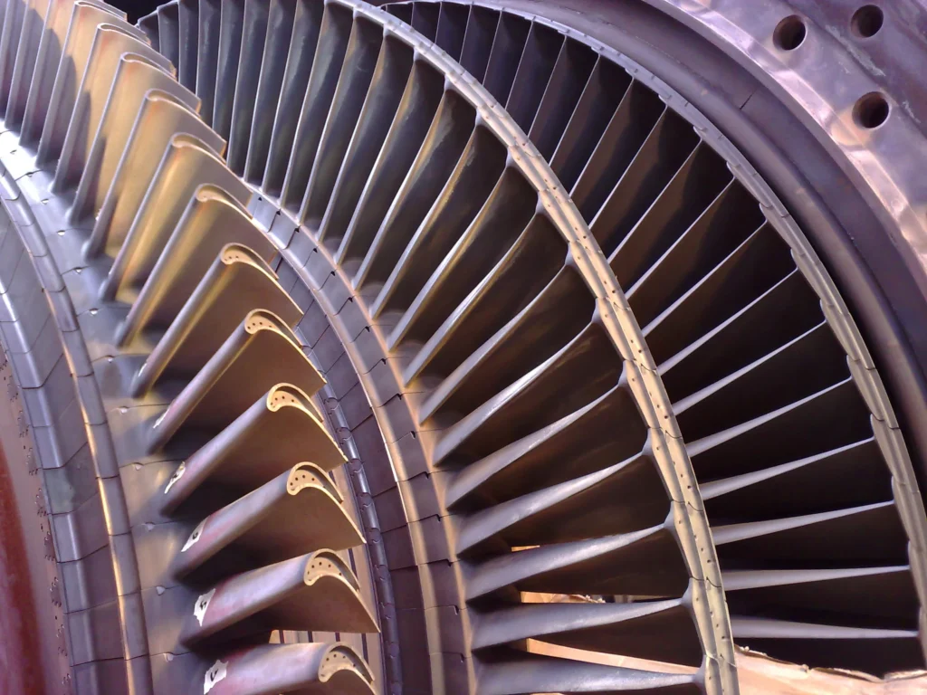
There are different types of steam turbines, including:
- Impulse Turbines: These turbines operate based on the principle of impulse, where high-velocity jets of steam are directed onto the turbine blades.
- Reaction Turbines: These turbines operate on the principle of both impulse and reaction, with steam expanding both as it passes over the blades and as it expands through them.
Steam turbines are crucial components in power plants, where they are often used in conjunction with other systems to generate electricity. They have been a key technology for power generation for over a century and continue to play a significant role in the production of electricity worldwide.
Small sized steam turbines are used in a variety of applications ranging from power generation in small-scale power plants to mechanical drives in industrial equipment. A steam turbine is a machine that converts thermal energy from steam into mechanical energy. Small sized steam turbines typically generate power in the range of a few kilowatts to several megawatts.
The design of small sized steam turbines typically involves several stages of blades that expand steam to create rotational force. The steam turbine rotor is typically mounted on bearings and rotates on a shaft. The steam is fed into the turbine through nozzles and directed onto the blades, causing the rotor to spin. The rotational force is transferred to a generator or other equipment to produce electricity or mechanical power.
Small sized steam turbines are used in various industries, including food processing, chemical, and pharmaceutical industries. They are used to power various machines and equipment, such as pumps, compressors, and fans. They are also used for combined heat and power (CHP) applications, where steam generated by a boiler is used to drive a steam turbine and produce both electricity and heat for industrial processes.
Steam Turbine Advantages
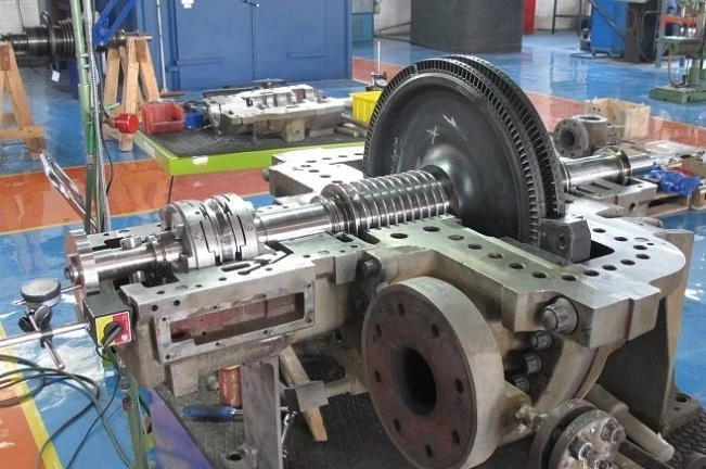
Advantages of small sized steam turbines include their high efficiency and reliability. They can also operate on a variety of fuels, including coal, oil, and natural gas. Additionally, small sized steam turbines can be designed to operate at varying loads, making them suitable for use in a wide range of applications.
However, there are also some disadvantages to using small sized steam turbines. They require regular maintenance to ensure optimal performance and can be expensive to operate and maintain. Additionally, the initial capital cost of a steam turbine can be high.
In summary, small sized steam turbines are an important source of power and mechanical energy in various industries. They offer high efficiency and reliability, making them suitable for a wide range of applications. However, they require regular maintenance and can be expensive to operate and maintain.
Dependability and versatility of equipment are vital to today’s process plants, pharmaceutical producers, mining interests, and a host of other users including, of course, petroleum, petrochemical, and chemical-process industries.
Operating pressures and temperatures are constantly rising; single-train capacities grow by leaps and bounds; continuity of service becomes a vital force, and the economy demands longer and longer periods between overhauls. Steam turbines are faithful partners to the process industries. They have proved their basic reliability and today are showing a new versatility by keeping pace with every demand for higher capacity, speed, and reliability.
Wherever you look in the process industries, there are more mechanical drive turbines; wherever you look, both horsepower and speed go up, year after year. And wherever you look, technological advances are being incorporated into modern steam turbines. Many manufacturers deserve to be recognized for their ability to solve the tougher steam
turbine application problems.
Through advanced planning, imaginative research, persistent development, and painstaking evaluation, engineers have in the last quarter of this century created a whole new turbine generation: machines of sizes and speeds that were only dreamed of a few decades ago. Multiflow exhausts, solid rotors, highspeed bearings, taller last-stage blades (“buckets”), cam-operated valve gear and controls, and other highly sophisticated control systems and computerized designs are a few of the innovations that helped make this progress
Knowledgeable manufacturers have available a wide selection of steam end designs, either single or multivalve, to meet any specific pressure and temperature conditions. The overwhelming majority of cases both industrial and cogeneration systems designed for electric power generation uses a simple, single-casing steam turbine. These turbines (Fig. 1.1) can be designed to provide operating flexibility to
economically utilize steam from a variety of sources to supply:
- Direct or geared power input for compressors, pumps, or other driven equipment
- Steam at the pressures and quantities required for integrated processes or lower-pressure turbines
- The electric power desired
- Cogenerated power for sale to the local utility
Overview of Steam Turbine
Fundamentals
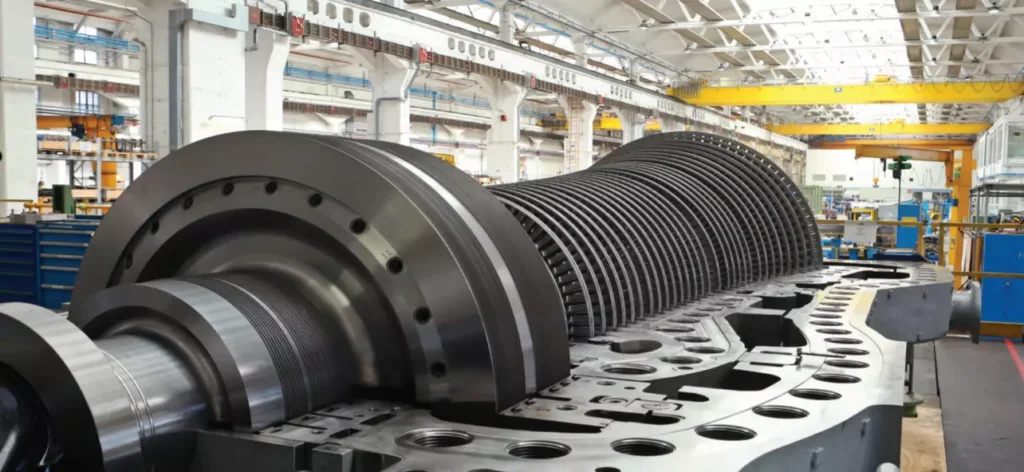
Before discussing turbine selection, let’s review how a steam turbine converts the heat energy of steam into useful work. The nozzles and diaphragms in a turbine are designed to direct the steam flow into well-formed, high-speed jets as the steam expands from inlet to exhaust pressure. These jets strike moving rows of blades mounted on the rotor. The blades convert the kinetic energy of the steam into the rotation energy of the shaft.
There are two principal turbine types: reaction and impulse. In a reaction turbine, the steam expands in both the stationary and moving blades. The moving blades are designed to utilize the steam jet energy of the stationary blades and to act as nozzles themselves. Because they are moving nozzles, a reaction force—produced by the pressure drop across them—supplements the steam jet force of the stationary blades. These combined forces cause rotation.
To operate efficiently the reaction turbine must be designed to minimize leakage around the moving blades. This is done by making most internal clearances relatively small. The reaction turbine also usually requires a balance piston (similar to those used in large centrifugal compressors) because of the large thrust loads generated. Because of these considerations, the reaction turbine is seldom used for mechanical drive in the United States, despite its occasionally higher initial efficiency. Reaction turbines are, nevertheless, in widespread use in Europe and the rest of the world.
They deserve to be discussed and will be dealt with later. The impulse turbine has little or no pressure drop across its moving blades. Steam energy is transferred to the rotor entirely by the steam jets striking the moving blades
Steam Turbine Description and Components
A steam turbine is a device that converts thermal energy from pressurized steam into mechanical work, which can then be used to generate electricity or perform other mechanical tasks. It is a type of heat engine that operates on the principle of converting the energy contained in high-pressure steam into rotational motion.
The basic components of a steam turbine include:
- Rotor: The rotor is the rotating part of the turbine that converts the steam’s kinetic energy into mechanical work. It typically consists of multiple blades or buckets attached to a central shaft.
- Stator: The stator is the stationary part of the turbine that contains fixed blades or nozzles. It guides the flow of steam onto the rotor blades, providing the necessary direction and control.
- Steam Inlet: The steam inlet is where high-pressure steam enters the turbine. It is connected to a steam source, such as a boiler, and the steam is directed into the turbine for expansion.
- Exhaust Outlet: The exhaust outlet is where the low-pressure steam exits the turbine after performing work. It is usually connected to a condenser or other steam utilization system.
- Governor: The governor is a control mechanism that regulates the steam flow and maintains a constant speed of the turbine, ensuring stable operation.
Steam turbines are commonly used in power plants to generate electricity. They can be categorized into different types based on their design and operational characteristics, such as condensing or non-condensing turbines, impulse or reaction turbines, and single-stage or multi-stage turbines.
The efficiency of a steam turbine depends on various factors, including the steam pressure and temperature, turbine design, and operating conditions. Steam turbines can achieve high efficiency levels, especially in combined cycle power plants where waste heat from the turbine is recovered and used to generate additional power.
Overall, steam turbines have been widely used for power generation due to their reliability, scalability, and ability to utilize a variety of fuel sources, including fossil fuels and renewable energy sources such as biomass or geothermal steam.
Rotor
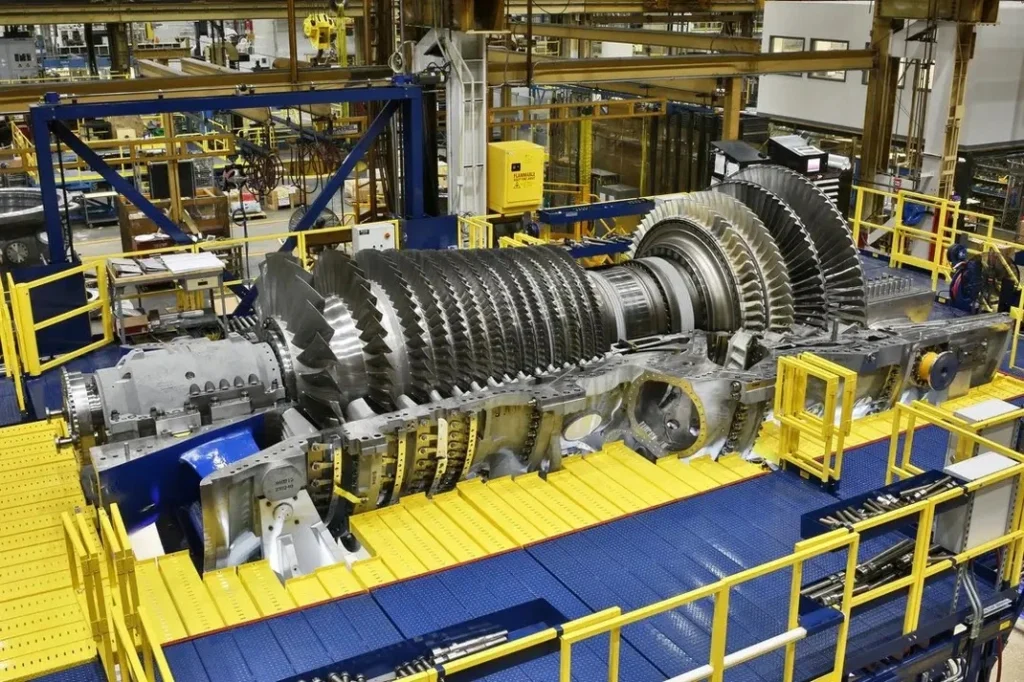
The rotor is a crucial component of a steam turbine. It is the rotating part of the turbine that converts the kinetic energy of the steam into mechanical work. The rotor typically consists of a central shaft and multiple blades or buckets attached to it.
The main function of the rotor is to extract energy from the high-pressure and high-temperature steam flowing through the turbine. As the steam passes over the blades, it imparts a force on them, causing the rotor to rotate. The rotation of the rotor is what generates the mechanical work that can be used for various applications, such as generating electricity in a power plant or driving industrial machinery.
The design and construction of the rotor are critical to ensure efficient and reliable operation of the steam turbine. The blades or buckets are shaped in a way that optimizes the flow of steam and maximizes the energy transfer. They are carefully engineered to withstand high temperatures, pressures, and centrifugal forces.
Depending on the type and size of the steam turbine, the rotor can have different configurations. In impulse turbines, the blades are arranged in a radial or axial configuration, and the steam acts on them in discrete stages. In reaction turbines, the blades are shaped to react to the steam continuously as it passes over them.
The rotor is connected to the generator or the mechanical load being driven by the turbine. The rotational motion of the rotor is transmitted to the generator or load through a coupling or a gearbox, where it is converted into electrical power or mechanical work, respectively.
Efficient and well-designed rotors are essential for the overall performance and output of a steam turbine. They undergo rigorous engineering analysis and testing to ensure they can withstand the operating conditions and deliver the desired power output while maintaining reliability and durability.
Stator
The stator is another important component of a steam turbine. It is the stationary part of the turbine that surrounds the rotor. The stator is responsible for directing and controlling the flow of steam as it passes through the turbine, converting the kinetic energy of the steam into mechanical work.
The primary function of the stator is to house the stationary blades or vanes that guide the flow of steam onto the rotor blades. These stationary blades are designed to optimize the flow of steam, ensuring efficient energy transfer and maximum power output. The stator blades are typically curved or angled to direct the steam in the desired direction and maintain a uniform flow.
In addition to guiding the steam flow, the stator also serves to support and protect the rotor and other internal components of the turbine. It provides structural stability and helps maintain the alignment of the rotor and stator blades.
The stator is typically constructed using high-quality materials that can withstand the high temperatures, pressures, and mechanical stresses encountered in the steam turbine. It is often made of steel or other alloys with excellent heat resistance and mechanical properties.
In large steam turbines, the stator is composed of multiple sections or stages, each with its set of stationary blades. These stages are designed to progressively extract energy from the steam as it passes through the turbine, improving the overall efficiency of the system.
The stator is an integral part of the steam turbine, working in conjunction with the rotor to convert steam energy into mechanical work. Together, they form a highly efficient and reliable power generation system used in various industries, including power plants, refineries, and industrial processes.
Steam Inlet
The steam inlet, also known as the steam admission or steam entry, is the point of entry for high-pressure steam into the steam turbine. It is a crucial component that allows the steam to enter the turbine and initiate the power generation process.
The steam inlet is typically located on the outer casing of the turbine and is connected to the steam source, such as a boiler or steam generator. The high-pressure steam flows through the steam inlet and enters the turbine at a specific angle and velocity.
To ensure efficient and controlled entry of steam into the turbine, the steam inlet is designed with various features. These include:
- Nozzles: The steam inlet may have a set of nozzles or guide vanes that help control the flow direction and velocity of the steam entering the turbine. These nozzles are adjustable and can be positioned to optimize the steam flow for maximum efficiency.
- Steam Strainers: Steam strainers or filters are sometimes installed at the steam inlet to remove any solid particles or impurities from the steam. These strainers help protect the turbine blades from damage and ensure smooth operation.
- Steam Control Valves: Steam control valves are often installed at the steam inlet to regulate the flow of steam into the turbine. These valves can adjust the steam flow rate and pressure, allowing for precise control of the turbine’s power output.
- Expansion Joints: Expansion joints are used at the steam inlet to accommodate thermal expansion and contraction of the turbine components. They help maintain the integrity of the turbine casing while allowing for the necessary movement caused by temperature variations.
The design and configuration of the steam inlet may vary depending on the specific type and size of the steam turbine. The goal is to ensure efficient steam flow, minimize pressure losses, and protect the turbine from any potential damage.
Overall, the steam inlet plays a critical role in the steam turbine’s operation by allowing high-pressure steam to enter the turbine and initiate the energy conversion process. Its design and functionality are crucial for optimizing turbine performance and ensuring reliable power generation.
Exhaust Outlet
The exhaust outlet, also known as the exhaust nozzle or exhaust diffuser, is the point of exit for the steam or gas after it has passed through the turbine and performed its work. It is an essential component of a steam turbine system as it allows the spent steam or gas to be discharged safely and efficiently.
The exhaust outlet is typically located at the opposite end of the turbine from the steam or gas inlet. It is designed to convert the high-velocity, high-pressure steam or gas into a lower-velocity, lower-pressure state before it is released into the surrounding environment or directed to further use, such as for heating or industrial processes.
The exhaust outlet performs several important functions:
- Pressure Reduction: The exhaust outlet is designed to gradually decrease the pressure of the steam or gas as it expands and flows through the turbine. This pressure reduction allows the steam or gas to exit the turbine at a lower pressure, minimizing the risk of sudden pressure changes that could damage the turbine or associated equipment.
- Velocity Control: The exhaust outlet helps control the velocity of the exhaust steam or gas as it exits the turbine. By gradually increasing the cross-sectional area of the outlet, the steam or gas velocity is reduced, which helps to minimize noise and prevent any potential damage to downstream components.
- Energy Recovery: In some cases, the exhaust outlet may be connected to a heat recovery system or condenser. This allows for the extraction of additional energy from the exhaust steam or gas by recovering heat or converting it into usable power. This improves the overall efficiency of the turbine system.
- Noise Reduction: The design of the exhaust outlet may incorporate features such as diffusers or silencers to reduce noise generated by the high-velocity exhaust steam or gas. This helps to meet noise regulations and maintain a quieter operating environment.
The specific design and configuration of the exhaust outlet may vary depending on the size, type, and application of the steam turbine. Factors such as exhaust pressure, flow rate, and temperature are considered in the design to optimize turbine performance and ensure safe operation.
Overall, the exhaust outlet is a critical component of a steam turbine system, responsible for safely and efficiently discharging the spent steam or gas. Its design aims to control pressure, velocity, and noise while allowing for energy recovery when applicable.
Governor of the Steam Turbine
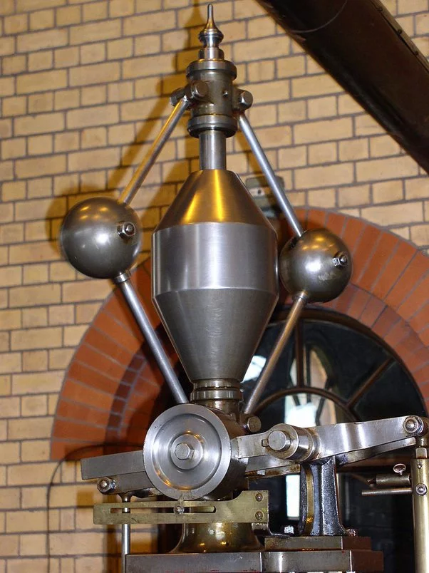
The governor is an important control device used in steam turbines to regulate the speed and output power of the turbine. Its main function is to maintain a constant rotational speed of the turbine within a desired range, regardless of changes in the load or steam conditions.
The governor operates based on the principle of feedback control, where it continuously monitors the speed of the turbine and adjusts the steam flow to maintain the desired speed. Here’s a brief overview of how the governor works:
- Speed Sensing: The governor is equipped with speed-sensing mechanisms such as centrifugal weights or magnetic pickups that detect the rotational speed of the turbine. These sensors provide input signals to the governor control system.
- Control System: The governor control system processes the speed signals and compares them to the desired speed setpoint. It calculates the error between the actual speed and the setpoint and determines the necessary adjustments to be made.
- Steam Flow Regulation: Based on the error signal, the governor control system adjusts the steam flow rate entering the turbine. This is typically achieved by modulating the steam control valves that regulate the steam flow. If the turbine speed is below the setpoint, the governor increases the steam flow, and if the speed is above the setpoint, it decreases the steam flow.
- Feedback Loop: The governor continuously monitors the turbine speed and makes ongoing adjustments to the steam flow to maintain the desired speed. It operates in a closed-loop feedback system, where it compares the measured speed with the setpoint and adjusts the steam flow accordingly.
The governor ensures stable operation of the steam turbine by responding to changes in load demand and maintaining a constant speed. It helps to prevent overspeed or underspeed conditions that could potentially damage the turbine or cause operational issues. Additionally, the governor provides a means of controlling the output power of the turbine, allowing it to respond to changes in the electrical grid or other power system requirements.
Modern steam turbines often utilize advanced electronic or digital governor systems that offer more precise control and flexibility. These systems may incorporate additional features such as load sharing between multiple turbines, protection functions, and communication interfaces for integration into broader control systems.
Overall, the governor plays a crucial role in the safe and efficient operation of steam turbines by regulating the turbine speed and power output to meet the desired operating conditions.
Steam Turbine Application Areas
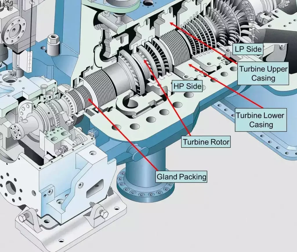
Steam turbines are used in a wide variety of applications, including:
- Power generation: Steam turbines are the most common type of prime mover used in power plants to generate electricity. They are also used in combined heat and power (CHP) plants to generate both electricity and heat.
- Industrial processes: Steam turbines are used in a variety of industrial processes, such as oil refining, chemical processing, and papermaking. They are used to drive compressors, pumps, and other machinery.
- Marine propulsion: Steam turbines are used to power large ships, such as aircraft carriers and cruise ships.
- Transportation: Steam turbines are used to power some locomotives and other rail vehicles.
Here are some specific examples of how steam turbines are used in different industries:
- Power generation: In the power generation industry, steam turbines are used to drive generators to produce electricity. The steam is typically generated by a boiler, which is heated by burning fossil fuels or nuclear fuel. The steam then drives the turbine blades, which rotate the generator shaft. The generator shaft is connected to a rotor, which generates electricity as it rotates.
- Industrial processes: In the industrial process industry, steam turbines are used to drive a variety of machinery, such as compressors, pumps, and fans. Steam turbines are also used to generate heat for industrial processes, such as drying products and distilling liquids.
- Marine propulsion: In the marine propulsion industry, steam turbines are used to power large ships, such as aircraft carriers and cruise ships. The steam turbines drive propellers, which propel the ship through the water.
- Transportation: In the transportation industry, steam turbines are used to power some locomotives and other rail vehicles. Steam turbines are also used to power some electric power plants that are built on trains.
Steam turbines are a versatile and efficient type of prime mover that can be used in a wide variety of applications. They are a key component of the global energy infrastructure.
Power Generation with Steam Turbines
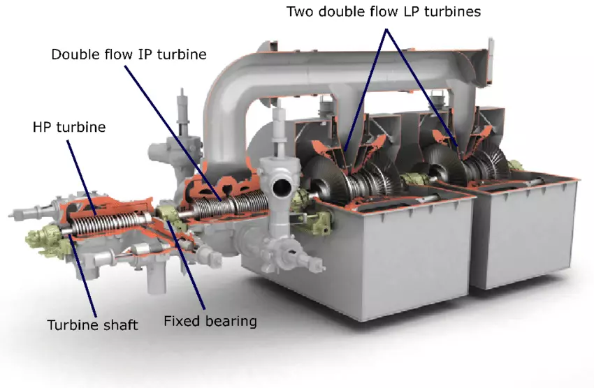
Steam turbines are used to generate electricity in power plants by converting the thermal energy of steam into mechanical energy. The steam is generated in a boiler by heating water with fossil fuels, nuclear fuel, or renewable energy sources such as solar or geothermal energy. The high-pressure steam is then fed to the steam turbine, where it expands and drives the turbine blades. The turbine blades are connected to a shaft, which rotates a generator to produce electricity.
There are two main types of steam turbines used in power generation:
- Condensing steam turbines: Condensing steam turbines are the most common type of steam turbine used in power plants. They operate by condensing the steam that exits the turbine back into water. This allows the turbine to operate at a higher efficiency.
- Backpressure steam turbines: Backpressure steam turbines are used in combined heat and power (CHP) plants to generate both electricity and heat. They operate by extracting some of the steam from the turbine before it is fully expanded. This steam is then used to provide heat for industrial processes or buildings.
Steam turbines are an efficient and reliable way to generate electricity. They are also very versatile and can be used to generate electricity from a variety of energy sources.
- Boiler: The boiler heats water to generate steam.
- Superheater: The superheater heats the steam to a higher temperature.
- Reheater: The reheater heats the steam after it has expanded through the high-pressure turbine.
- High-pressure turbine: The high-pressure turbine extracts some of the energy from the steam.
- Low-pressure turbine: The low-pressure turbine extracts the remaining energy from the steam.
- Condenser: The condenser condenses the steam back into water.
- Feedwater pump: The feedwater pump pumps the condensed water back to the boiler.
- Generator: The generator converts the mechanical energy of the turbine shaft into electricity.
Steam turbines play a vital role in the global energy infrastructure. They are a key component of the transition to a clean energy future, as they can be used to generate electricity from a variety of renewable energy sources.
Industrial Processes where Steam Turbine is Used
Steam turbines are used in a wide variety of industrial processes, including:
- Oil refining: Steam turbines are used to drive compressors, pumps, and other machinery in oil refineries. They are also used to generate heat for distillation processes.
- Chemical processing: Steam turbines are used to drive compressors, pumps, and other machinery in chemical plants. They are also used to generate heat for chemical reactions.
- Papermaking: Steam turbines are used to drive machinery in paper mills, such as pulpers, paper machines, and dryers. They are also used to generate heat for drying paper.
- Food and beverage processing: Steam turbines are used to drive machinery in food and beverage processing plants, such as conveyors, mixers, and cookers. They are also used to generate heat for sterilization and pasteurization processes.
- Textile manufacturing: Steam turbines are used to drive machinery in textile mills, such as spinners, weavers, and finishers. They are also used to generate heat for drying and dyeing textiles.
- Metalworking: Steam turbines are used to drive machinery in metalworking shops, such as rolling mills, presses, and saws. They are also used to generate heat for heat treatment processes.
Here are some specific examples of how steam turbines are used in different industrial processes:
- Oil refining: In the oil refining industry, steam turbines are used to drive compressors that compress crude oil to high pressures. The compressed oil is then fed to distillation columns, where it is separated into different fractions, such as gasoline, diesel fuel, and jet fuel. Steam turbines are also used to drive pumps that circulate oil through the refinery and to generate heat for distillation processes.
- Chemical processing: In the chemical processing industry, steam turbines are used to drive compressors that compress gases, such as air, nitrogen, and hydrogen. The compressed gases are then used in a variety of chemical processes, such as ammonia production and fertilizer manufacturing. Steam turbines are also used to drive pumps and mixers, and to generate heat for chemical reactions.
- Papermaking: In the papermaking industry, steam turbines are used to drive pulpers that break down wood chips into fibers. The fibers are then mixed with water and chemicals to form a slurry, which is then fed to a paper machine. The paper machine forms the slurry into a sheet of paper, which is then dried and finished. Steam turbines are used to drive all of the machinery in a paper mill, as well as to generate heat for drying paper.
- Food and beverage processing: In the food and beverage processing industry, steam turbines are used to drive conveyors that transport food and beverage products through the processing plant. They are also used to drive mixers and cookers, and to generate heat for sterilization and pasteurization processes.
- Textile manufacturing: In the textile manufacturing industry, steam turbines are used to drive spinners that spin yarn from fibers. The yarn is then fed to a weaver to create fabric, which is then finished. Steam turbines are used to drive all of the machinery in a textile mill, as well as to generate heat for drying and dyeing textiles.
- Metalworking: In the metalworking industry, steam turbines are used to drive rolling mills that roll metal sheets and plates into different shapes. They are also used to drive presses that punch or stamp metal parts, and saws that cut metal. Steam turbines are used to drive all of the machinery in a metalworking shop, as well as to generate heat for heat treatment processes.
Steam turbines are an essential part of many industrial processes. They provide a reliable and efficient way to power machinery and generate heat.
Marine propulsion with Steam Turbines
Steam turbines have been used for marine propulsion for over a century. They were the dominant form of marine propulsion in the early 20th century, but they have since been largely replaced by diesel engines. However, steam turbines are still used in some large ships, such as aircraft carriers and cruise ships.
Steam turbines are a good choice for marine propulsion because they are efficient and reliable. They can also be used to generate a lot of power, which is needed for large ships. However, steam turbines are also complex and expensive to build and maintain.
- Boiler: The boiler heats water to generate steam.
- Superheater: The superheater heats the steam to a higher temperature.
- Reheater: The reheater heats the steam after it has expanded through the high-pressure turbine.
- High-pressure turbine: The high-pressure turbine extracts some of the energy from the steam.
- Low-pressure turbine: The low-pressure turbine extracts the remaining energy from the steam.
- Condenser: The condenser condenses the steam back into water.
- Feedwater pump: The feedwater pump pumps the condensed water back to the boiler.
- Propeller: The propeller is driven by the turbine shaft and propels the ship through the water.
Steam turbine propulsion systems are typically used in large ships, such as aircraft carriers and cruise ships. These ships need a lot of power to propel them through the water, and steam turbines can provide that power.
Steam turbines are also used in some submarines. Submarines need to be able to operate quietly, and steam turbines can be operated very quietly. This is important because it allows submarines to avoid detection.
Overall, steam turbines are a good choice for marine propulsion because they are efficient, reliable, and can generate a lot of power. However, they are also complex and expensive to build and maintain.
EMS Power Machines
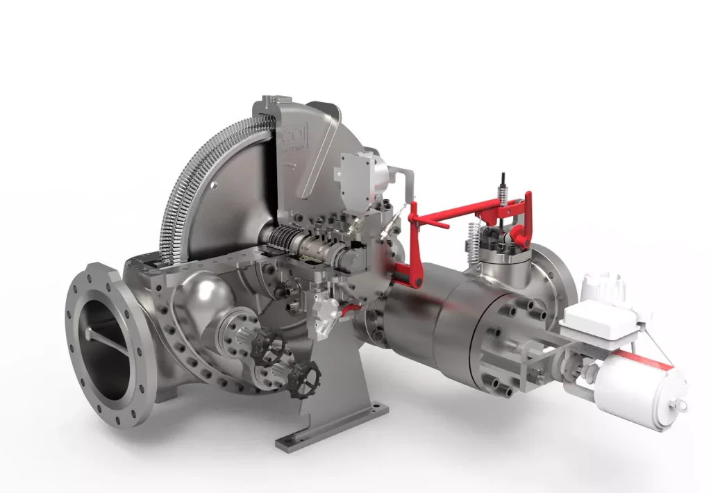
We design, manufacture and assembly Power Machines such as – diesel generators, electric motors, vibration motors, pumps, steam engines and steam turbines
EMS Power Machines is a global power engineering company, one of the five world leaders in the industry in terms of installed equipment. The companies included in the company have been operating in the energy market for more than 60 years.
EMS Power Machines manufactures steam turbines, gas turbines, hydroelectric turbines, generators, and other power equipment for thermal, nuclear, and hydroelectric power plants, as well as for various industries, transport, and marine energy.
EMS Power Machines is a major player in the global power industry, and its equipment is used in power plants all over the world. The company has a strong track record of innovation, and it is constantly developing new and improved technologies.
Here are some examples of Power Machines’ products and services:
- Steam turbines for thermal and nuclear power plants
- Gas turbines for combined cycle power plants and industrial applications
- Hydroelectric turbines for hydroelectric power plants
- Generators for all types of power plants
- Boilers for thermal power plants
- Condensers for thermal power plants
- Reheaters for thermal power plants
- Air preheaters for thermal power plants
- Feedwater pumps for thermal power plants
- Control systems for power plants
- Maintenance and repair services for power plants
EMS Power Machines is committed to providing its customers with high-quality products and services. The company has a strong reputation for reliability and innovation. Power Machines is a leading provider of power equipment and services, and it plays a vital role in the global power industry.
EMS Power Machines, which began in 1961 as a small factory of electric motors, has become a leading global supplier of electronic products for different segments. The search for excellence has resulted in the diversification of the business, adding to the electric motors products which provide from power generation to more efficient means of use.