Gasification Plants: Gasification plants are advanced industrial facilities designed to convert carbonaceous feedstocks—such as coal, biomass, municipal solid waste, industrial residues, or other organic materials—into a clean, combustible synthesis gas (syngas). This process takes place in a controlled environment where the feedstock reacts with a limited amount of oxygen, steam, or air at high temperatures, typically between 800°C and 1500°C. Unlike direct combustion, which fully oxidizes the material to release heat, gasification partially oxidizes the feedstock to produce syngas, a mixture primarily composed of carbon monoxide (CO), hydrogen (H₂), carbon dioxide (CO₂), methane (CH₄), and trace amounts of other gases. This syngas can then be used as a versatile energy carrier for power generation, heating, production of synthetic fuels, and as a feedstock for the chemical industry.
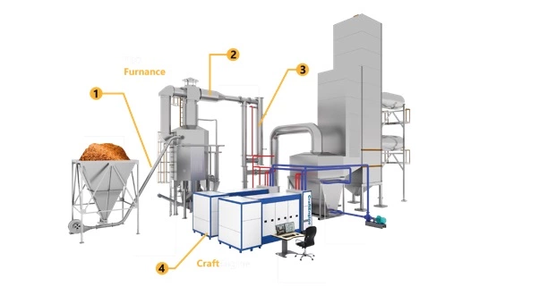
The structure of a gasification plant is based on a series of interconnected systems that ensure efficient and continuous operation. At its core lies the gasifier itself, where the thermochemical reactions occur. Surrounding this central unit are subsystems for feedstock preparation and feeding, oxygen or air supply, syngas cooling and cleaning, ash and slag handling, energy conversion, and control systems. Each of these parts plays a crucial role in maintaining the quality of syngas, the reliability of operations, and compliance with environmental regulations. Modern plants often include advanced gas cleaning systems capable of removing particulates, tars, heavy metals, and sulfur compounds, which makes syngas suitable for sensitive applications such as gas turbines or chemical synthesis.
One of the key advantages of gasification plants is their ability to handle a wide range of fuels. While traditional coal gasification plants dominated in the past, modern facilities increasingly focus on biomass, waste, and other renewable or recycled feedstocks. This flexibility allows gasification to support the transition to sustainable energy by reducing reliance on fossil fuels and enabling waste-to-energy solutions. Additionally, gasification provides higher efficiency and lower emissions compared to direct combustion, especially when integrated with combined cycle power plants (IGCC) or when combined with carbon capture and storage (CCS) technologies. In such cases, syngas can be cleaned and conditioned before combustion, leading to a significant reduction in greenhouse gas emissions.
Gasification plants also serve as a bridge between the energy and chemical industries. Syngas can be further processed to produce synthetic natural gas (SNG), liquid fuels via Fischer–Tropsch synthesis, hydrogen for fuel cells, or valuable chemicals like methanol and ammonia. This versatility positions gasification as a cornerstone of the circular economy, where waste and residues are transformed into valuable resources. Furthermore, the integration of digital monitoring and advanced process control in modern plants enhances operational safety, efficiency, and flexibility, allowing rapid adaptation to different feedstocks and market demands.
Gasification Plants
Gasification plants can be classified into several main types depending on the design of the gasifier, the method of feedstock introduction, the flow of gases and solids inside the reactor, and the application for which the syngas is intended. Each type has its own advantages, limitations, and preferred areas of use. The four principal categories of gasifiers used in large-scale plants are fixed-bed gasifiers, fluidized-bed gasifiers, entrained-flow gasifiers, and plasma gasifiers.
Fixed-Bed Gasifiers
These are the oldest and simplest types of gasifiers. The feedstock remains largely in solid form as gases pass through it. Depending on the direction of the gas flow relative to the feedstock, they are subdivided into:
- Updraft (counter-current): Air or oxygen enters from below while the syngas exits at the top. This design achieves high efficiency and can handle fuels with high moisture but often produces tars in the syngas.
- Downdraft (co-current): Both feedstock and gases flow downward together, resulting in cleaner syngas with low tar content, though it requires dry, uniform fuel.
Fixed-bed gasifiers are well-suited for small- to medium-scale applications, especially for biomass and waste feedstocks.
Fluidized-Bed Gasifiers
These gasifiers use a bed of inert material, such as sand, kept in motion by upward-flowing gas (air, oxygen, or steam). Feedstock is introduced into this turbulent environment, which ensures good mixing, uniform temperatures, and efficient conversion. Types include:
- Bubbling Fluidized Bed (BFB): The gas flow is moderate, creating bubbles within the bed. It offers good fuel flexibility and moderate tar levels.
- Circulating Fluidized Bed (CFB): Higher gas velocities carry bed material and unreacted feedstock out of the reactor, which are then recirculated. This design allows large-scale operation, uniform temperature distribution, and high efficiency.
Fluidized-bed gasifiers are widely used for biomass and waste, as well as for coal in large plants.
Entrained-Flow Gasifiers
In this type, finely ground feedstock is injected with oxygen or air and steam into a reactor at very high temperatures (over 1200°C). The feedstock reacts almost instantly, producing a tar-free syngas with very low methane content. Ash is typically removed as molten slag. Entrained-flow gasifiers are the preferred choice for large-scale coal and petroleum coke gasification, as well as for integrated gasification combined cycle (IGCC) power plants. However, they require finely pulverized fuel and careful feed preparation.
Plasma Gasifiers
Plasma gasification uses an electric arc or plasma torch to generate extremely high temperatures (2000–5000°C). This environment breaks down feedstock completely into syngas and vitrified slag. Plasma gasifiers are especially effective for hazardous waste, municipal solid waste, and complex materials that are difficult to process with conventional methods. While they produce very clean syngas, their energy requirements are high, making them more suitable for specialized applications.
Additional Variants and Emerging Types
- Dual-Fuel Gasifiers: Designed to handle mixed feedstocks (e.g., coal and biomass).
- Hydrothermal Gasification: Operates with wet biomass or sludge at supercritical water conditions, eliminating the need for drying.
- Chemical-Looping Gasifiers: Use solid oxygen carriers to separate nitrogen from the process, improving syngas purity.
Fixed-Bed Gasifiers
Fixed-bed gasifiers represent the earliest and most traditional form of gasification technology, and they remain relevant today due to their relatively simple design, robustness, and adaptability to smaller-scale applications. The fundamental principle of a fixed-bed gasifier is that the solid feedstock—whether coal, biomass, or waste-derived material—is introduced into a vertical reactor, forming a packed bed through which the oxidizing agent (air, oxygen, or steam) flows. The physical arrangement of the feedstock stays largely intact, with the gases moving through the interstices of the solid material, allowing for gradual conversion into a combustible syngas. Depending on the configuration of gas and solid flow, fixed-bed gasifiers are typically classified as updraft (counter-current) or downdraft (co-current), with some less common variations such as crossdraft designs used in niche applications.
The fixed-bed design is characterized by clearly defined thermal zones that appear along the height of the bed. At the top, feedstock enters and undergoes drying through contact with rising hot gases. Below this, in the pyrolysis zone, the material is decomposed by heat into char, tar vapors, and volatiles. Further down lies the oxidation zone, where oxygen or air reacts with the carbonaceous char, generating high temperatures. Finally, at the bottom, the reduction zone allows carbon dioxide and steam to react with hot char to form additional carbon monoxide and hydrogen, enriching the syngas. This stratified arrangement makes fixed-bed gasifiers relatively easy to understand, operate, and maintain, while also offering predictable gas compositions depending on the operating mode.
In updraft fixed-bed gasifiers, the oxidizing agent enters from below the bed and syngas exits at the top. The rising hot gases first dry the incoming fuel, then pyrolyze and partially oxidize it, producing high thermal efficiency and an ability to process fuels with high moisture or ash content. However, a major drawback of this configuration is the high tar content in the syngas, as the volatiles released in the upper part of the bed are not sufficiently cracked before exiting the reactor. This makes the gas less suitable for direct use in engines or turbines without additional cleaning or reforming stages. Updraft systems are therefore commonly used for heating applications, low- to medium-scale power generation with extensive gas cleaning, or in situations where fuel quality is inconsistent.
In contrast, downdraft fixed-bed gasifiers allow both feedstock and gasifying agent to flow downward together, with syngas leaving from the bottom. This design forces volatiles released during pyrolysis to pass through the hot oxidation and reduction zones, where many of the tars are thermally cracked into simpler gases. The result is a much cleaner syngas with significantly lower tar levels compared to updraft systems, making it more suitable for small power generation units, internal combustion engines, and distributed energy systems. The trade-off, however, is that downdraft gasifiers demand relatively dry and uniform feedstock, and they tend to have lower efficiency than updraft types due to less effective heat recovery from the rising gases.
A crossdraft fixed-bed gasifier represents a less common variation, where air enters from the side and the syngas exits on the opposite side. This design has a compact layout and can deliver gas rapidly, but it typically suffers from poor fuel conversion and uneven temperature distribution. Crossdraft systems are sometimes used in small-scale or mobile applications where space and rapid startup are priorities, but they are not as widely applied in modern industrial practice.
The advantages of fixed-bed gasifiers are strongly linked to their mechanical simplicity and robustness. They are comparatively inexpensive to build and operate, require minimal moving parts, and can handle a variety of fuels, especially in the updraft design. Their ability to operate with relatively high-moisture biomass makes them attractive in rural or agricultural settings where fuel drying infrastructure is limited. Furthermore, their stratified thermal zones provide stable operation and predictable performance, making them suitable for users who require dependable, low-maintenance systems.
On the other hand, limitations are also well recognized. Tar formation remains the most significant challenge, particularly in updraft systems, which restricts the direct usability of the gas for advanced energy conversion technologies without costly gas cleaning. Fuel flexibility, while a strength in some designs, is restricted in others; downdraft systems, for instance, require carefully sized and conditioned feedstock to prevent blockages, channeling, or unstable operation. Scaling fixed-bed gasifiers to very large capacities is also problematic, as uneven gas distribution and excessive pressure drops occur in large beds, confining their practicality mainly to small- and medium-scale plants.
Despite these challenges, fixed-bed gasifiers continue to be deployed across a range of applications, particularly where simplicity, ruggedness, and moderate syngas quality are acceptable trade-offs. In many developing regions, small biomass gasifiers based on the downdraft principle are used to generate electricity for off-grid communities, powering diesel engine generators with producer gas substitution. In industrial settings, updraft fixed-bed systems are used to gasify coal or biomass for process heat or to feed boilers. Additionally, research continues on hybrid approaches, combining fixed-bed principles with advanced tar cracking or gas cleaning technologies to improve syngas quality while retaining the operational benefits of the design.
In summary, fixed-bed gasifiers remain a cornerstone of gasification technology due to their longevity, adaptability, and straightforward operation. While they may not match the scale or syngas purity of entrained-flow or plasma gasifiers, they fill an important niche in distributed energy, rural electrification, small industrial power generation, and heating. By carefully matching the type of fixed-bed gasifier—updraft for high efficiency with tolerant fuel flexibility, downdraft for cleaner syngas at smaller scales, or crossdraft for specialized compact applications—to the intended use, operators can harness the benefits of gasification with relatively low capital and operational complexity.
The main parts of a fixed-bed gasifier are designed to create a stable flow of feedstock, maintain the thermochemical reaction zones, and extract syngas and by-products efficiently. Each component plays a specific role in ensuring proper gasification performance, syngas quality, and system durability. While the exact design can vary depending on whether the configuration is updraft, downdraft, or crossdraft, the fundamental elements remain similar. The main parts can be grouped as follows:
1. Feedstock Inlet and Hopper
The feed system begins with a hopper or storage bin where the raw fuel (biomass, coal, or waste-derived material) is stored before entering the reactor. From the hopper, the material is fed into the top of the gasifier by gravity. In some designs, feeding screws, conveyors, or lock-hoppers are added to maintain a continuous feed and prevent air leakage. The inlet must ensure uniform distribution of feedstock to avoid channeling and uneven bed formation.
2. Gasifier Reactor Vessel (Main Body)
This is the central chamber where the gasification reactions occur. It is typically a vertical cylindrical or rectangular vessel constructed from refractory-lined steel to withstand high temperatures. Inside the reactor, distinct thermal and reaction zones are established in a vertical sequence:
- Drying Zone (upper region): moisture in the feedstock is evaporated by contact with rising hot gases.
- Pyrolysis Zone (middle region): volatile compounds are released, leaving behind char.
- Oxidation/Combustion Zone (lower middle): oxygen reacts with part of the char, producing heat and creating CO₂ and H₂O.
- Reduction Zone (lowest part): CO₂ and H₂O react with the hot char to form CO and H₂, the main components of syngas.
The geometry and insulation of the reactor body are crucial for maintaining stable temperature profiles and ensuring efficient conversion.
3. Air / Oxygen / Steam Inlet (Tuyeres or Nozzles)
These are ports or nozzles through which the gasifying agent (air, oxygen, or steam) is introduced into the reactor. In updraft gasifiers, the inlets are located near the bottom, allowing gases to rise upward. In downdraft designs, the air is often introduced through side nozzles at the oxidation zone, forcing volatiles to pass through the hottest zone for tar cracking. The placement and design of tuyeres greatly influence syngas composition, tar levels, and overall efficiency.
4. Grate or Support Bed
At the bottom of the reactor lies a grate or support system that holds the solid bed of fuel while allowing ash, char, and slag to fall through. The grate also ensures that gases can pass upward (in updraft) or downward (in downdraft) through the fuel bed without obstruction. In modern systems, moving or rotating grates are sometimes used to avoid blockages and maintain continuous operation.
5. Ash and Char Removal System
Unreacted char, ash, and inert residues collect at the bottom of the reactor and must be removed continuously or periodically. Systems include mechanical ash screws, lock-hoppers, or manual removal depending on the scale of the plant. In updraft systems, this part must also handle higher amounts of unconverted char, while downdraft systems usually produce finer ash due to more complete fuel utilization.
6. Syngas Outlet
The exit for syngas is positioned differently depending on the type of fixed-bed gasifier:
- Updraft: the outlet is at the top, where gas leaves after passing through the drying zone.
- Downdraft: the outlet is located at the bottom or side, after gas has passed through the hot reduction zone for tar cracking.
- Crossdraft: the outlet is on the opposite side from the air inlet, allowing lateral gas flow.
The outlet is often connected to a cyclone or primary gas cleaning system to remove particulates before further use.
7. Refractory Lining and Insulation
The inner walls of the reactor are lined with refractory materials to withstand temperatures often exceeding 1000°C. This lining protects the steel shell from damage, minimizes heat loss, and ensures thermal stability of the reaction zones. Proper insulation is critical for efficiency and longevity of the gasifier.
8. Gas Cleaning and Cooling (External but Essential)
Although not part of the core reactor body, every fixed-bed gasifier is paired with gas cleaning equipment. This usually includes:
- Cyclones to remove particulates.
- Scrubbers or filters to capture tar, dust, and other contaminants.
- Coolers/heat exchangers to reduce syngas temperature before use in engines or turbines.
In updraft systems, this stage is especially important due to the high tar load in raw syngas.
9. Instrumentation and Control Systems
Modern fixed-bed gasifiers include temperature sensors, pressure gauges, flow meters, and automated control systems. These instruments help monitor bed conditions, prevent blockages, control feed rates, and maintain desired gas quality. Advanced control ensures safe and efficient operation, especially in continuous industrial setups.
Feedstock Inlet and Hopper
The feedstock inlet and hopper of a fixed-bed gasifier form the first critical interface between the raw material supply chain and the reactor itself. Their design, construction, and operation have a direct influence on the stability of the gasification process, the continuity of operation, and the quality of the syngas produced. Since fixed-bed gasifiers rely on a packed column of solid feedstock through which gases flow, the manner in which the material enters and settles in the bed is fundamental to ensuring uniform reaction conditions. Any irregularities in feeding—such as bridging, channeling, or surges—can disturb the bed structure, alter temperature distributions, and reduce efficiency. For this reason, engineers place considerable emphasis on the configuration of the feedstock inlet system and its integration with the reactor body.
At the most basic level, the hopper serves as a storage and buffer system that holds a sufficient quantity of feedstock above the gasifier to guarantee continuous operation. In small-scale downdraft gasifiers used for rural electrification with biomass, the hopper may be a simple vertical cylinder with a conical bottom feeding directly into the reactor throat by gravity. In larger or industrial systems, however, the hopper is designed as part of a lock-hopper arrangement to allow periodic refilling without disturbing the internal pressure or allowing air leakage into the reactor. These lock-hopper systems are especially important in pressurized gasifiers, where any uncontrolled air ingress would not only compromise syngas quality but also create serious safety hazards.
The inlet design must also account for the physical characteristics of the feedstock. Coal, for example, can be delivered in graded lumps of uniform size, which flow predictably through a chute or hopper. Biomass, on the other hand, presents greater challenges because it tends to be irregular in shape, lightweight, fibrous, and sometimes sticky when moist. Such characteristics can lead to bridging, where the feedstock forms an arch inside the hopper and stops flowing, or rat-holing, where the material flows only in a narrow channel, leaving stagnant zones. To prevent these problems, engineers often use mechanical agitators, screw feeders, or vibratory systems inside or beneath the hopper to ensure a consistent flow into the bed. The choice of feeder must be carefully matched to the type of biomass—wood chips, pellets, rice husks, or agricultural residues each behave differently under gravity feeding.
Another key function of the hopper and feed inlet is to minimize unwanted air entry into the reactor. Fixed-bed gasifiers rely on carefully controlled oxygen input through designated tuyeres or nozzles, and any additional air entering via the feed system can create uncontrolled combustion zones. To avoid this, hoppers are usually sealed, and when mechanical feeding systems are used, they incorporate airlocks or double-valve arrangements. In pressurized systems, where the reactor may operate at several bars above atmospheric pressure, lock-hopper feeding not only maintains sealing but also stages the pressure reduction between ambient and reactor levels to protect equipment and operators.
The thermal environment around the feed inlet also requires careful management. Since the top of the bed is the drying zone in most fixed-bed designs, hot gases rising from below transfer heat to the incoming feedstock. This process enhances drying efficiency but can also expose the hopper to elevated temperatures. If not properly insulated or cooled, the hopper walls may suffer damage or allow pre-ignition of feedstock inside the chute. Some designs incorporate water jackets or cooling systems around the upper section of the reactor and hopper to maintain safe operating temperatures and extend equipment life.
Dust, fines, and foreign objects represent additional concerns in the design of the feedstock inlet. Excessive fines can clog the bed, increase pressure drop, and reduce permeability for gases. Oversized particles, meanwhile, may create voids or cause uneven bed packing. For this reason, the feedstock supply system often includes screening and sizing equipment upstream of the hopper to ensure a uniform feed. Metal tramp removal systems, such as magnetic separators, are also common in waste-derived fuel applications, preventing damage to feeders or blockages in the gasifier throat.
In terms of operational strategy, the hopper acts as both a buffer and a regulator of feedstock delivery. Operators must monitor the fill level continuously to avoid starvation (leading to unstable gas quality) or overfilling (which can overload the bed and cause poor gas distribution). Modern gasifiers often integrate sensors, such as ultrasonic or radar level detectors, to provide continuous feedback on hopper contents. Automated controls then adjust feeding mechanisms—whether conveyors, screws, or rotary valves—to maintain a steady fuel column within the reactor. This automation not only improves consistency but also reduces labor requirements and minimizes human error in complex industrial environments.
From an environmental and safety perspective, the hopper and inlet system must also be designed to control emissions and operator exposure. In small open-top systems, smoke, dust, and gases can escape during refilling, posing hazards to workers. Advanced hoppers, particularly in waste and coal gasification plants, are fully enclosed and may include extraction systems to capture fugitive dust and vapors. In addition, safety interlocks prevent operators from opening feed inlets while the reactor is pressurized or in operation. Such measures are essential for compliance with occupational health standards and environmental regulations.
Looking forward, innovations in hopper and feed inlet design continue to evolve, particularly with the push toward greater fuel flexibility in biomass and waste gasification. Researchers are developing adaptive feeding systems that can handle heterogeneous mixtures without extensive preprocessing. For example, twin-screw feeders and fluidized lock-hopper systems are being tested to overcome bridging and flow issues. Moreover, integration with digital monitoring tools allows predictive maintenance of feeding equipment, ensuring that blockages or wear are detected before they lead to unplanned downtime.
In summary, the feedstock inlet and hopper of a fixed-bed gasifier, while seemingly simple components, are in fact highly engineered subsystems that play a pivotal role in process stability and efficiency. They must reliably deliver a uniform stream of feedstock, prevent air ingress, manage thermal exposure, and ensure operator safety. The success of the entire gasification process hinges on the performance of this first stage, because even the most advanced reactor and gas cleaning technologies cannot compensate for inconsistent or irregular feeding. For this reason, careful attention to hopper design, feeding mechanisms, sealing systems, and monitoring tools is a defining feature of modern fixed-bed gasifier engineering.
The feedstock inlet and hopper in a fixed-bed gasifier play a fundamental role in determining the efficiency and stability of the entire gasification process, as they establish the first point of contact between the raw material and the reactor system. The hopper is not only a storage unit but also a buffer zone that guarantees a consistent supply of feedstock into the gasifier, ensuring that the column of solid material inside the reactor remains stable and evenly distributed. Because fixed-bed gasifiers rely on a packed bed through which gases pass to initiate drying, pyrolysis, oxidation, and reduction reactions, the way the material enters the bed can directly influence the uniformity of temperature gradients and the permeability of gases. Any disruption at this stage, such as uneven feeding or bridging of biomass in the hopper, can disturb gas flow and create inefficiencies that compromise syngas quality. For this reason, feedstock inlets are carefully engineered to promote uninterrupted gravity flow or are supplemented with mechanical feeding systems when dealing with difficult fuels.
The design of the feedstock inlet and hopper is strongly tied to the type of material being processed, whether coal, biomass, or waste-derived fuels. Coal, with its predictable particle size and density, generally flows smoothly through hoppers, requiring only basic gravity-fed chutes. Biomass, however, introduces significant challenges due to its irregular shapes, low bulk density, and fibrous texture. Materials like wood chips or agricultural residues tend to form arches or bridges inside the hopper, preventing a continuous flow into the reactor. To overcome these challenges, engineers incorporate screw feeders, vibratory systems, or rotary valves beneath the hopper, which mechanically agitate the material and prevent flow interruptions. In pressurized fixed-bed gasifiers, the inlet system also includes lock-hopper mechanisms that not only regulate the feed but also maintain the pressure seal, preventing unwanted air ingress that could disrupt the controlled oxygen balance inside the reactor. These lock-hopper systems are essential in large-scale industrial applications, where maintaining reactor integrity and operator safety are non-negotiable.
Thermal management is another important consideration in the design of feedstock inlets and hoppers. Since the top of the gasifier bed typically functions as the drying zone, hot gases rise and transfer heat to the incoming feedstock. While this is beneficial for reducing the moisture content of the material, it also exposes the hopper walls to elevated temperatures. If left unprotected, this can cause structural damage or lead to pre-ignition of the feedstock before it enters the main reactor zones. To mitigate these risks, refractory linings, cooling jackets, or external insulation are commonly used to keep temperatures within safe limits. The hopper must also be designed to withstand mechanical stresses from large volumes of fuel while ensuring minimal leakage of gases or particulates into the environment. In modern systems, enclosed hoppers are equipped with dust extraction systems to maintain clean operation and protect workers from exposure to fine particles or volatile gases that might escape during refilling.
The functionality of the feedstock inlet extends beyond simply delivering material; it also plays a key role in maintaining the chemical environment within the gasifier. Fixed-bed gasification is highly sensitive to uncontrolled oxygen inflow, as even small leaks can create unwanted combustion zones that disrupt the carefully staged reactions in the reactor. Therefore, the sealing of the feed inlet is as critical as its feeding performance. In industrial plants, sophisticated double-valve arrangements or rotary airlocks ensure that no ambient air enters the system during fuel loading. For smaller-scale downdraft biomass gasifiers, simpler sealed hoppers may suffice, but even in these cases, poor sealing can result in erratic syngas quality and operational instability. These considerations highlight that the feedstock inlet, although often underestimated, is a decisive factor in maintaining both process efficiency and operational safety.
In practice, the feedstock inlet and hopper are also tightly integrated with fuel preparation systems. Since syngas quality and reactor performance depend on uniform fuel size and moisture, upstream processing often includes screening, drying, and densification of biomass into pellets or briquettes. This preprocessing ensures smooth flow through the hopper and consistent gasification reactions in the bed. Without such measures, irregular feedstock could cause blockages, uneven gas flow, or incomplete conversion, resulting in higher tar formation or reduced calorific value of the syngas. In waste-to-energy applications, the hopper is typically paired with magnetic separators or shredders to remove foreign materials before they can enter the reactor. This not only protects feeding equipment but also prevents operational disruptions caused by contaminants.
Automation and monitoring are increasingly important in modern feedstock inlet and hopper systems, especially as gasification plants move toward more continuous and industrialized operation. Advanced level sensors using radar or ultrasonic technology monitor the amount of material in the hopper in real time, feeding data into control systems that regulate feeding rates. This automation allows operators to maintain a consistent bed height inside the reactor, preventing starvation or overloading. In some designs, sensors are also used to detect bridging or irregular flow, triggering corrective measures such as mechanical agitation or feed adjustments. Combined with predictive maintenance technologies, these digital tools reduce downtime, improve efficiency, and make gasification plants more reliable.
The role of the feedstock inlet and hopper in a fixed-bed gasifier thus extends far beyond simple material delivery. It encompasses the regulation of fuel flow, the protection of reactor integrity, the control of air ingress, the management of thermal and mechanical stresses, and the integration with fuel preparation and automation systems. Their design is particularly influential in determining whether a gasifier operates with stable syngas output and minimal downtime or suffers from frequent disruptions and inconsistent gas quality. In smaller-scale applications, such as rural biomass gasification units, the simplicity and low cost of the feed system are advantageous, but even here, reliability remains essential to ensure local power supply. In large-scale industrial plants, the feedstock inlet and hopper become highly engineered subsystems, reflecting the complexity and demands of modern energy production. Ultimately, by ensuring continuous, safe, and uniform feeding, the feedstock inlet and hopper form the foundation on which the entire efficiency and performance of a fixed-bed gasifier is built.
The reactor vessel of a fixed-bed gasifier is the central structure in which the entire gasification process takes place, and its design largely determines the efficiency, stability, and longevity of the plant. This vessel is usually a vertical, refractory-lined steel chamber that accommodates the different thermal and chemical zones required for drying, pyrolysis, oxidation, and reduction of the feedstock. The feedstock inlet and hopper supply the material from above, and as it descends by gravity, it passes through these reaction zones in sequence, while the oxidizing agents such as air, oxygen, or steam are introduced through nozzles or tuyeres at carefully chosen points along the reactor wall. The geometry of the reactor vessel, the distribution of air inlets, and the type of grate or support system at the bottom are all critical factors that dictate gas flow, heat transfer, and the quality of syngas produced. In an updraft fixed-bed gasifier, the oxidizing agent enters at the bottom, allowing gases to rise counter-current to the descending fuel, which leads to high thermal efficiency but syngas rich in tar vapors. In downdraft designs, the oxidizing medium is introduced near the middle of the reactor, forcing volatiles to pass through the hot combustion zone before leaving at the bottom, which results in a much cleaner syngas more suitable for power generation engines. Crossdraft versions, though less common, introduce gases from the side and rely on a lateral flow across the bed, offering compactness at the expense of efficiency and uniformity.
The materials and construction of the reactor vessel must be robust enough to withstand continuous exposure to high temperatures often exceeding 1000°C as well as corrosive gases, abrasive feedstock particles, and thermal cycling. To achieve this, the vessel is lined with refractory materials that provide thermal insulation and protect the steel shell from chemical attack and heat damage. The choice of refractory lining depends on the type of feedstock and operating temperature; alumina, silica, and high-chromium bricks are commonly used in coal-based gasifiers, while biomass systems may use lighter linings optimized for lower ash content. The internal design also takes into account the accumulation of ash and slag, which must be directed toward the grate and ash removal system without obstructing the syngas flow. In pressurized gasifiers, the vessel must also handle significant internal pressures, requiring thicker steel shells, stronger welds, and precisely engineered seals. These design considerations make the reactor vessel one of the most complex and costly components of a fixed-bed gasifier.
Within the reactor vessel, the stability of the fuel bed is crucial for uniform reaction conditions. The packed bed must allow gases to flow evenly without channeling, which can lead to hot spots, incomplete conversion, or excessive tar formation. This is why the distribution of the feedstock from the inlet and the maintenance of a proper bed height are closely linked to the vessel’s performance. The tuyeres or nozzles that inject air or oxygen into the bed are strategically placed to maintain even combustion and to prevent localized overheating that could damage the refractory lining. The flow of the oxidizing medium must also be carefully balanced to ensure that only partial oxidation occurs, since excessive oxygen supply would result in direct combustion instead of gasification, thereby reducing syngas yield and efficiency. By maintaining these delicate balances within the reactor vessel, the fixed-bed gasifier can operate continuously with predictable performance and a steady output of syngas.
The design of the reactor vessel is also influenced by the type and quality of feedstock being used. Coal gasifiers, for example, are typically designed to handle larger particle sizes and higher ash content, requiring strong grates and effective slag tapping systems at the bottom. Biomass gasifiers, on the other hand, must accommodate lower bulk density, variable moisture content, and fibrous particles, which may demand taller vessels to ensure sufficient residence time for complete conversion. Waste-derived fuels add further challenges due to their heterogeneous composition, requiring vessels that can tolerate irregular feeding, variable ash melting points, and unpredictable contaminants. These differences highlight why fixed-bed gasifiers are not one-size-fits-all solutions but rather need tailored reactor designs to match the intended fuel source and application.
Modern reactor vessels are often equipped with advanced monitoring and control instruments to ensure optimal operation. Thermocouples placed at different heights within the vessel allow operators to track temperature profiles across the drying, pyrolysis, oxidation, and reduction zones, ensuring that each stage is performing as intended. Pressure sensors monitor gas flow resistance through the bed, providing early warnings of blockages or excessive ash buildup on the grate. In larger plants, sophisticated control systems automatically adjust the air supply, feed rate, and bed height to stabilize syngas quality even as fuel properties vary. This integration of digital monitoring into the reactor vessel design enhances reliability and safety, while also maximizing fuel utilization and reducing downtime caused by manual adjustments.
The reactor vessel of a fixed-bed gasifier is thus far more than a simple container; it is a carefully engineered core system where the transformation of solid feedstock into gaseous fuel is orchestrated through precise temperature control, gas distribution, and material handling. Its performance determines the composition of the syngas, the amount of tar and particulates produced, and the overall efficiency of the plant. Without a properly designed and well-maintained reactor vessel, even the best feeding system, gas cleaning units, or downstream equipment cannot deliver consistent results. For this reason, the vessel is often considered the heart of the gasifier, where engineering decisions on materials, geometry, and process integration directly shape the plant’s capability to produce clean and reliable syngas for power generation, industrial heat, or chemical synthesis.
The air, oxygen, or steam inlet system in a fixed-bed gasifier is one of the most critical subsystems because it determines how effectively the chemical reactions inside the reactor vessel proceed and how the quality of the syngas evolves during operation. These inlets, often designed as tuyeres or nozzles strategically located along the walls of the vessel, are responsible for introducing the oxidizing medium that enables partial combustion and generates the heat required to sustain the endothermic reactions of pyrolysis and reduction. Unlike full combustion systems, the gasifier depends on a carefully controlled supply of oxygen or air to avoid complete burning of the feedstock, which would only yield heat instead of syngas. The balance between oxygen, air, or sometimes steam injection is what makes gasification distinct, as the limited oxygen presence allows carbon-rich feedstock to break down into carbon monoxide, hydrogen, and other useful gases. Steam injection is particularly important in many designs because it reacts with hot carbon to produce additional hydrogen, thereby enhancing the calorific value and quality of the syngas. The precise ratio of oxidizing agents injected through the inlets is continuously monitored and adjusted to ensure stable operation and high conversion efficiency.
The geometry and durability of these inlet nozzles are essential for the long-term stability of the gasifier. Since they are exposed directly to extremely high temperatures and the corrosive environment of the reactor interior, they are typically manufactured from heat-resistant alloys or coated with refractory materials that resist chemical wear. In some gasifiers, the inlets are water-cooled or designed with protective linings to prevent them from burning out or clogging with ash and slag. The positioning of the inlets along the vertical reactor wall must also ensure even distribution of the oxidizing medium so that localized hot spots do not form, which could crack the refractory lining or cause inconsistent syngas production. In downdraft gasifiers, the placement of inlets around the oxidation zone forces volatiles to pass through intense heat, reducing tar levels and producing cleaner gas, while in updraft systems, the inlets at the bottom supply rising streams of air or oxygen that generate strong counter-current heat transfer and high efficiency but leave more tar in the gas stream. This demonstrates how the inlet system directly influences the chemical profile of the resulting gas.
The flexibility of the inlet system also makes it possible for operators to adapt to different types of feedstock. Biomass with high moisture content may require more oxygen injection to generate the additional heat needed to drive off excess water, whereas coal or char-based feedstocks may demand less air but more steam injection to optimize hydrogen yield. The valves and flow control units connected to these nozzles are therefore designed for precise modulation, often linked to sensors within the vessel that provide real-time feedback on temperature and pressure. Modern gasifiers often integrate automated control loops where sensors detect fluctuations in the reaction zones and adjust inlet flows almost instantly, maintaining stable syngas composition despite changes in fuel quality or load demand. This automation not only improves efficiency but also extends the lifespan of the inlet nozzles by preventing extreme operating conditions that accelerate wear and tear.
The inlet system is also closely tied to safety, as the wrong balance of oxygen or air could easily shift the process from controlled partial oxidation to uncontrolled combustion, leading to overheating, refractory damage, or even pressure build-up and explosions. To mitigate this risk, most gasifiers are equipped with purge systems that can flush the nozzles with inert gases such as nitrogen or carbon dioxide during startup, shutdown, or emergency situations. Additionally, nozzles are designed to minimize backflow of hot gases, which could otherwise reach the external piping and damage sensitive control equipment. This level of engineering highlights the dual role of the inlet system: not only to provide the correct amounts of oxidizing agents for efficient syngas generation but also to safeguard the entire gasification plant against dangerous operating conditions.
As fixed-bed gasifiers evolve, the inlet systems are increasingly optimized for higher flexibility and integration with advanced control systems. Computational fluid dynamics simulations are used during design to predict how injected gases will distribute inside the vessel and how they will interact with the descending bed of fuel. By fine-tuning nozzle positions and flow rates, engineers can minimize channeling effects, where gases bypass parts of the bed and cause uneven reactions. Innovations also include multi-stage injection systems that allow the operator to vary the type of gas introduced at different levels of the reactor, enabling more precise control of reaction zones. This level of sophistication allows modern fixed-bed gasifiers to handle a wider range of fuels, produce cleaner syngas, and operate with higher thermal efficiency compared to earlier designs.
The air, oxygen, and steam inlet system is therefore a key enabler of the gasification process, directly shaping the thermal environment of the reactor vessel, dictating the balance between combustion and reduction, and ultimately determining the quality and usability of the syngas produced. Without a carefully engineered and well-maintained inlet system, a fixed-bed gasifier cannot achieve the level of stability and efficiency required for industrial power generation, chemical synthesis, or combined heat and power applications. It is this subsystem that transforms the concept of gasification from a theoretical chemical process into a controlled, repeatable, and industrially viable operation.
Gasifier Reactor Vessel (Main Body)
The gasifier reactor vessel, often referred to as the main body, is the core and most defining component of a fixed-bed gasifier, acting as the physical and functional framework where the entire sequence of gasification reactions unfolds. It is a vertically oriented, cylindrical or rectangular structure made of heavy-gauge steel with a refractory lining inside to withstand the extreme thermal and chemical conditions of operation. The design of this main body dictates not only the durability of the plant but also the efficiency of the conversion process, as the reactor vessel must contain and guide the different thermochemical zones—drying, pyrolysis, oxidation, and reduction—that the feedstock passes through as it descends by gravity. The dimensions and internal configuration of the reactor vessel are carefully engineered to ensure that the descending fuel maintains adequate residence time in each zone, that the rising gases flow evenly without channeling, and that the oxidizing agents introduced via tuyeres or nozzles mix effectively with the fuel bed. It is in this vessel that the solid feedstock undergoes its transformation into a combustible mixture of gases, making the main body the true heart of the gasifier.
The refractory lining within the reactor vessel plays an indispensable role by providing thermal insulation, reflecting heat back into the reaction zones, and protecting the steel shell from chemical corrosion and mechanical abrasion. Depending on the operating conditions and the type of feedstock, the refractory may consist of high-alumina bricks, silica compounds, or specialized castables that resist slag attack and maintain integrity under thermal cycling. In biomass gasifiers, the refractory must be optimized for lower ash contents and different melting characteristics, while in coal gasifiers it must tolerate more aggressive slags with higher fusion temperatures. The thickness of the refractory lining and the type of insulating backup material are also adjusted based on whether the gasifier operates at atmospheric or pressurized conditions. In pressurized designs, the reactor vessel walls must be reinforced with thicker steel shells and stronger welds to prevent rupture, while still allowing the lining to expand and contract during heating and cooling cycles without cracking. These technical considerations illustrate how much of the vessel’s reliability and service life depend on the careful choice and maintenance of the refractory system.
The reactor vessel also integrates with several crucial subsystems that determine its overall performance. At the top, it connects seamlessly with the feedstock inlet and hopper, allowing the controlled introduction of solid fuel without excessive air leakage that would disturb the process balance. Along its midsection, the vessel is equipped with the air, oxygen, or steam inlets that supply oxidizing agents for partial combustion and reduction reactions, while the geometry of the wall ensures that these gases distribute evenly through the fuel bed. At the bottom, the main body interfaces with the grate and ash removal system, where the residual char, ash, and slag are discharged without allowing excessive syngas losses or backflow of air. Openings along the vessel are designed to extract syngas at the optimal point, depending on whether it is an updraft, downdraft, or crossdraft configuration. Each of these connections must be engineered with airtight seals, wear-resistant fittings, and proper cooling arrangements to maintain continuous operation and prevent process upsets.
Thermal and mechanical stresses place significant demands on the structural integrity of the reactor vessel, and as such, it is often the most expensive and carefully monitored part of a gasifier plant. The main body must endure sustained exposure to temperatures exceeding 1000°C in some zones, combined with the abrasive action of descending solids and the chemical attack of reducing and oxidizing gases. In addition to wear from normal operation, the vessel must withstand frequent startups and shutdowns, during which expansion and contraction cycles can cause refractory cracking or steel deformation. To manage these stresses, many modern reactor vessels incorporate expansion joints, segmented refractory layers, and water-cooled jackets at critical locations. Regular inspection and maintenance schedules are essential, as even small cracks in the refractory or leaks in the vessel shell can lead to serious operational inefficiencies, contamination of syngas, or safety hazards.
The geometry of the main body also defines the operational behavior of the gasifier. In tall and narrow vessels, fuel has a longer residence time, allowing for more complete conversion and a smoother temperature gradient, which is particularly beneficial for biomass with high moisture content. In shorter, wider vessels, the flow of gases may be less uniform, but they allow higher throughput and can handle fuels with larger particle sizes or more irregular shapes. The design of the vessel therefore must be tailored to the intended feedstock and the desired syngas output, balancing efficiency, throughput, and ease of maintenance. Computational fluid dynamics modeling and pilot-scale testing are often used in modern engineering practice to optimize vessel geometry before full-scale construction, reducing the risks of uneven flow, incomplete conversion, or tar accumulation.
From an operational perspective, the gasifier reactor vessel also serves as the central point for process monitoring and control. Embedded thermocouples, pressure sensors, and gas sampling ports provide continuous data on the internal environment, allowing operators to track the stability of the drying, pyrolysis, oxidation, and reduction zones. These measurements are critical for adjusting feed rates, air or oxygen supply, and steam injection in real time, ensuring that the process remains in balance and that syngas quality remains consistent. By integrating these monitoring systems into the vessel design, modern gasifiers can achieve higher automation, reduced operator intervention, and improved process reliability compared to earlier, manually controlled units.
Ultimately, the gasifier reactor vessel represents the convergence of structural engineering, materials science, thermodynamics, and chemical process design. Its role as the main body of the plant makes it the single most important element in determining whether the system produces a steady, high-quality syngas stream or suffers from inefficiencies, high tar levels, and frequent breakdowns. A well-designed and properly maintained reactor vessel enables a fixed-bed gasifier to operate continuously for thousands of hours, efficiently converting a wide range of feedstocks into valuable energy. Without this central component, the carefully orchestrated interaction of feedstock inlet, oxidizing agent injection, syngas outlet, and ash removal would be impossible, underscoring why the main body is regarded as the heart of the gasification process.
The syngas outlet system of a fixed-bed gasifier is the pathway through which the gas mixture generated in the reactor vessel exits and moves toward downstream cooling and cleaning units, and its design is decisive in maintaining both efficiency and gas quality. Since syngas composition is directly influenced by the location and configuration of the outlet, the outlet system is carefully integrated into the body of the gasifier at the level that best suits the specific type of fixed-bed design. In updraft gasifiers, the syngas outlet is located at the top of the reactor vessel, where the hot gases rise after passing through the drying and pyrolysis zones, carrying with them a significant load of tars and particulates. This configuration benefits from high thermal efficiency but creates additional demands on the outlet and subsequent cleaning systems. In downdraft gasifiers, by contrast, the syngas outlet is positioned at the bottom, after the gases have been forced downward through the intense oxidation zone, effectively cracking many of the tar vapors before they leave the reactor. This makes the outlet gas much cleaner and easier to use in engines or turbines. Crossdraft systems have lateral outlets, which allow compact designs but require precise flow control to ensure that the gas leaving through the outlet is representative of complete reaction rather than bypassing parts of the bed. In all these configurations, the outlet system must be airtight, thermally resistant, and designed to prevent leakage of combustible gases, as even small leaks could create serious safety hazards.
Because the syngas exiting the reactor vessel is typically at very high temperatures—sometimes in excess of 500°C—it must be directed through outlet ducts and piping capable of withstanding both heat and corrosive compounds. These outlet channels are often lined with refractory materials or equipped with water-cooled jackets to manage the thermal load and protect the steel casing from damage. Furthermore, the gas at this stage is heavily laden with dust, soot, ash particles, and condensable tars, which means the outlet system must not only provide a pathway for flow but also maintain a geometry that minimizes blockages and fouling. Smooth curves are preferred over sharp bends, as tar vapors condensing on cold spots can create deposits that clog the pipes. To mitigate this, the outlet ducts are sometimes insulated or actively heated to keep gas above tar condensation temperatures until it reaches the cleaning system. The design thus extends beyond a simple exit port, encompassing a managed flow environment that prepares the raw syngas for further conditioning.
The outlet system also plays a vital role in pressure control within the gasifier. Since the reactor operates slightly above atmospheric pressure in many designs, the syngas outlet must be fitted with valves and seals that maintain this pressure balance without allowing uncontrolled venting. In pressurized gasifiers, the outlet design becomes even more sophisticated, as it must prevent depressurization events and ensure a consistent flow into downstream pressurized cleaning and utilization units. Pressure sensors and control valves are often placed at the outlet to monitor flow rates, regulate backpressure, and stabilize the overall performance of the reactor vessel. In some cases, syngas recirculation loops are connected to the outlet, allowing a portion of the gas to be redirected back into the reactor for tar cracking or temperature stabilization. This level of integration demonstrates how the outlet system functions not in isolation, but as a dynamic part of the entire gasifier operation.
Another important consideration in outlet system design is safety. The syngas produced contains significant amounts of carbon monoxide, hydrogen, and other combustible gases, making it both flammable and toxic. To prevent leaks, all outlet joints and connections are fitted with high-integrity gaskets and flanges, often designed with double sealing arrangements. Flame arrestors or non-return valves may also be installed to prevent flashbacks from downstream combustion equipment into the gasifier. During startup and shutdown, when gas composition is unstable and may include excess tars or unreacted volatiles, the outlet system may be connected to flare stacks where the gas can be safely combusted instead of being fed into sensitive engines or turbines. This controlled management of gas during transient phases is crucial for both plant safety and reliability.
From a process perspective, the syngas outlet is the first stage of transition from chemical reaction to practical energy use. The quality of gas leaving the outlet directly affects the design requirements of the subsequent cleaning system, which may include cyclones, scrubbers, filters, or catalytic tar reformers. A poorly designed outlet that allows uneven flow or entrainment of excessive particulates will increase the load on these downstream units, leading to higher maintenance costs and shorter operational lifetimes. Conversely, a well-optimized outlet system that ensures uniform flow, maintains proper temperatures, and prevents localized condensation will ease the burden on cleaning systems and contribute to a more stable and economical gasification process. This is why in modern gasifier engineering, the outlet system is not treated as a secondary detail but as a primary factor influencing the plant’s performance.
The syngas outlet system is therefore not merely an exhaust pipe; it is an engineered component that serves multiple functions including flow management, thermal regulation, pressure stabilization, and safety assurance. It bridges the harsh and reactive environment of the reactor vessel with the more controlled stages of syngas cooling and cleaning, and any weakness in its design or maintenance can compromise the entire plant. By carefully managing the exit of the gas, preserving its energy content, and preventing hazards, the outlet system ensures that the gasifier delivers a steady, usable stream of syngas suitable for power generation, industrial processes, or synthesis of fuels and chemicals. In this sense, it is as critical to the gasification process as the main body of the reactor itself, completing the cycle from feedstock introduction to usable energy output.
The grate and ash removal system in a fixed-bed gasifier is a critical component that ensures the continuous operation of the plant by allowing the accumulation and controlled discharge of residual char, ash, and slag produced during gasification. This system is located at the bottom of the reactor vessel and serves both as a physical support for the descending fuel bed and as a mechanism for separating incombustible materials from the syngas. In fixed-bed designs, the grate must support a high column of solid feedstock while allowing gases to pass upward or downward depending on whether the system is updraft, downdraft, or crossdraft. The structural integrity, material composition, and geometry of the grate are therefore crucial for maintaining uniform gas flow, avoiding channeling, and preventing excessive pressure drop that could disrupt the controlled reaction zones above. In essence, the grate forms the interface between the high-temperature chemical environment within the reactor and the mechanical removal of residues, making it indispensable for both efficiency and safety.
The materials used for constructing grates are designed to withstand extreme temperatures, abrasive wear, and corrosive effects of ash and slag. High-grade alloys or water-cooled steel plates are commonly used in industrial fixed-bed gasifiers, and in some designs, refractory coatings are applied to further extend service life. The selection of materials is closely linked to the type of feedstock; coal gasifiers require more robust, slag-resistant grates capable of handling higher ash melting points, while biomass gasifiers often have grates optimized for lighter, fibrous feedstock that produces more fine ash and less molten slag. The spacing and size of openings in the grate are carefully calculated to permit the passage of ash while preventing large fuel particles from falling through prematurely, which could disrupt the uniformity of the bed and reduce conversion efficiency. In some advanced designs, moving or vibrating grates are employed to actively agitate the bed and prevent clogging or channel formation, ensuring even gas distribution and minimizing operational interruptions.
Ash and char removal is tightly integrated with the grate design. In updraft gasifiers, where the syngas exits from the top, the ash that collects on the grate must be continuously discharged to prevent accumulation that could block gas flow. Downdraft systems benefit from more complete combustion and reduction, which typically produces finer residual ash, but even here, effective removal mechanisms are essential to maintain a stable bed height and prevent backpressure. Mechanical systems such as screw conveyors, rotary valves, or ash rakes are often used to transport the ash from the bottom of the reactor to storage or disposal units. In pressurized gasifiers, these removal systems are often designed as lock-hoppers or double-valve arrangements to maintain pressure integrity while allowing continuous discharge. Proper design of the ash removal pathway is critical not only for maintaining operational stability but also for reducing maintenance downtime and ensuring safe handling of potentially hot, reactive residues.
The ash and grate system also influences the quality of the syngas. If ash accumulates excessively or is unevenly distributed across the grate, it can create localized hotspots or cold zones in the reactor, altering the temperature profile of the pyrolysis, oxidation, and reduction zones. These temperature variations can increase tar production, reduce overall carbon conversion, or result in fluctuating syngas composition, which complicates downstream gas cleaning and utilization. For this reason, careful attention is paid to the uniformity of ash flow and the mechanical reliability of the grate. Continuous monitoring through sensors can detect bed height, ash accumulation, or abnormal temperature variations near the grate, enabling operators to make timely adjustments or maintenance interventions.
Safety is another key function of the grate and ash removal system. Residual char can remain highly reactive and, if not properly cooled or discharged, may pose a fire hazard when exposed to air outside the reactor. To mitigate these risks, ash discharge systems often include water quenching, cooling conveyors, or sealed hoppers that prevent ignition while safely handling hot residues. In addition, the grate serves as a barrier preventing unwanted backflow of syngas and maintaining the integrity of the controlled atmosphere within the reactor vessel. Any failure in the grate or ash removal system can lead to sudden changes in pressure, potential damage to the refractory lining, or unsafe accumulation of combustible materials, highlighting its essential role in plant safety.
Modern fixed-bed gasifiers increasingly incorporate automation and monitoring into the grate and ash removal system. Sensors can measure the rate of ash discharge, detect blockages, and even assess the composition of residual char to provide feedback on the efficiency of the gasification reactions. In large-scale industrial applications, motorized or hydraulically actuated grates can be precisely controlled to maintain a constant bed height, optimize gas flow, and ensure continuous operation. The integration of these systems with the feedstock inlet, reactor vessel, and syngas outlet ensures that all components of the gasifier operate in harmony, maximizing fuel conversion efficiency, minimizing downtime, and producing a steady, reliable syngas output.
Overall, the grate and ash removal system is far more than a mechanical convenience; it is an integral part of the fixed-bed gasifier that maintains the structure of the fuel bed, ensures smooth gas flow, enables continuous discharge of residues, and safeguards both the quality of syngas and the safety of operations. Its performance directly affects the efficiency of the drying, pyrolysis, oxidation, and reduction zones within the reactor vessel, the cleanliness and usability of the syngas leaving the outlet, and the durability of the reactor itself. By combining robust materials, engineered geometry, controlled mechanical movement, and real-time monitoring, the grate and ash removal system ensures that the gasifier can operate efficiently and reliably, transforming feedstock into valuable syngas while handling the by-products safely and effectively.
The refractory lining and insulation of a fixed-bed gasifier are essential components that protect the structural integrity of the reactor vessel, ensure thermal efficiency, and maintain stable reaction conditions for syngas production. Since the gasification process involves temperatures that often exceed 1000°C in the combustion and reduction zones, the interior walls of the reactor are subjected to extreme thermal stress, chemical corrosion, and abrasive wear from descending fuel particles and ash. Without a properly engineered refractory lining, the steel shell of the reactor would quickly degrade, leading to structural failure, leaks of combustible syngas, or unsafe operating conditions. The lining serves not only as a physical barrier but also as a thermal buffer, reflecting heat back into the drying, pyrolysis, oxidation, and reduction zones, thereby maintaining the temperature gradients necessary for efficient conversion of feedstock into combustible gases. The choice of materials for the lining, their thickness, and method of installation are carefully tailored to the type of feedstock, operating temperature, and expected slag or ash characteristics.
High-alumina bricks, silica-based castables, magnesia-chrome composites, and other refractory materials are commonly used to construct the lining of industrial fixed-bed gasifiers. Coal gasifiers, which often deal with higher ash content and slagging tendencies, require robust refractory compositions capable of withstanding both chemical attack and the mechanical impact of larger fuel particles. Biomass gasifiers, while producing less slag, still demand refractory materials that can tolerate fibrous residues, variable moisture content, and uneven heating. In addition to the refractory bricks or castables themselves, insulating layers are often placed behind the lining to minimize heat loss through the reactor shell. This insulation not only improves the thermal efficiency of the gasifier, reducing fuel consumption and energy costs, but also protects the outer steel shell from thermal cycling that could otherwise lead to warping or cracking. Advanced designs may incorporate modular refractory panels, segmented castables, or even water-cooled sections in regions of extreme thermal stress, ensuring a long service life and ease of maintenance.
The lining also plays a critical role in controlling the gasification reactions within the reactor vessel. By maintaining consistent temperatures in each reaction zone, the refractory ensures that the feedstock passes through the drying, pyrolysis, oxidation, and reduction stages efficiently. In updraft gasifiers, the lining helps retain heat in the lower oxidation and reduction zones while allowing the rising syngas to carry heat upward, drying incoming feedstock and improving thermal efficiency. In downdraft designs, the refractory ensures that volatiles passing through the high-temperature oxidation zone are cracked effectively, reducing tar content in the syngas. Without proper refractory insulation, temperature fluctuations could lead to incomplete conversion, increased tar formation, uneven gas composition, and higher particulate loads, all of which complicate downstream gas cleaning and utilization.
Mechanical stresses and abrasion from feedstock particles are another consideration for the lining. Fixed-bed gasifiers handle descending solids that exert pressure on the walls, especially near the grate and ash collection zones, where char and slag accumulate. The refractory must resist erosion caused by these abrasive materials while maintaining structural cohesion over thousands of hours of operation. Some gasifiers incorporate protective coatings or sacrificial layers in high-wear areas to extend the lifespan of the lining. Additionally, proper installation with careful attention to expansion joints and thermal allowances is critical to prevent cracking or spalling of refractory panels, which could expose the steel shell and lead to catastrophic failure.
The refractory and insulation system also integrates with the overall control and monitoring strategy of the gasifier. Temperature sensors embedded within the lining or attached to its surface provide real-time feedback on the conditions in each reaction zone. This information allows operators to adjust feedstock flow, air or steam injection, and other process parameters to maintain stable operation. In advanced industrial plants, automated control systems use these readings to regulate the entire gasifier operation, ensuring consistent syngas composition and maximizing thermal efficiency. By combining robust materials, effective insulation, and continuous monitoring, the refractory lining becomes an active participant in process control rather than a passive protective barrier.
Finally, refractory lining and insulation directly influence the overall energy efficiency, safety, and maintenance of a fixed-bed gasifier. A well-engineered lining minimizes heat losses, reduces fuel requirements, stabilizes reaction zones, and protects the reactor vessel from chemical and mechanical damage. It allows the plant to handle a wide range of feedstocks, from coal to biomass and waste-derived fuels, while maintaining high-quality syngas production. Regular inspection and maintenance of the refractory, combined with careful design considerations, ensure long-term reliability and operational safety. In effect, the refractory lining and insulation form the backbone of the gasifier’s thermal and structural system, without which the complex interactions of feedstock, syngas, and reaction zones could not occur efficiently or safely.
Air / Oxygen / Steam Inlet (Tuyeres or Nozzles)
The air, oxygen, and steam inlet system, commonly realized through tuyeres or nozzles, is a critical subsystem in a fixed-bed gasifier that dictates the progression, efficiency, and stability of the gasification reactions occurring within the reactor vessel. These inlets are responsible for introducing the oxidizing agents required to initiate partial combustion, generate the necessary heat for endothermic reactions, and produce a syngas composition suitable for downstream utilization. Unlike conventional combustion, which aims for complete oxidation of the fuel, gasification relies on carefully controlled oxygen and air supply to convert carbonaceous feedstock into carbon monoxide, hydrogen, methane, and other combustible gases without excessive burning. Steam injection is often incorporated alongside air or oxygen to react with hot carbon and enhance hydrogen production through the water–gas shift reaction, improving both calorific value and flexibility of the syngas. The precise placement, flow rate, and composition of the oxidizing agents introduced through tuyeres or nozzles are therefore carefully engineered to maintain balanced reaction zones, prevent hotspots, and ensure uniform conversion of the feedstock.
Mechanically, tuyeres and nozzles must withstand extreme conditions within the reactor vessel, including temperatures exceeding 1000°C, abrasive particulate matter, corrosive gases, and chemical attack from molten ash or slag. As such, these components are typically manufactured from heat-resistant alloys or coated with refractory materials, and in larger industrial systems, water-cooled tuyeres are sometimes used to protect the structural integrity of the nozzle while maintaining precise control of gas injection. Their design also incorporates features to prevent clogging, backflow of hot gases, or erosion by the descending bed of fuel. Placement within the reactor is critical: in downdraft gasifiers, inlets are located near the midsection oxidation zone to force volatile gases through intense heat, effectively cracking tars and producing cleaner gas; in updraft designs, inlets at the bottom create counter-current flow with the rising syngas, optimizing thermal efficiency but producing syngas with higher tar content; and in crossdraft designs, lateral placement ensures compactness while demanding precise control of gas distribution. The geometry and angle of injection are therefore designed to achieve even mixing and maintain the desired temperature profiles across the bed.
Operational flexibility is another important aspect of the inlet system. Different feedstocks—coal, biomass, or waste-derived materials—have varying moisture contents, particle sizes, and chemical compositions, requiring adjustments to the amount of air, oxygen, or steam injected to sustain optimal reaction conditions. In biomass gasifiers, for example, higher moisture content may require increased oxygen or air to generate sufficient heat for drying, while steam injection can boost hydrogen yield. Flow control is usually achieved through precision valves, rotary feeders, or blowers that are integrated into automated control systems. These systems can adjust injection rates in real time based on temperature, pressure, and syngas composition readings, ensuring stable operation despite variations in fuel quality or load demand. Advanced designs also include multi-stage injection arrangements that allow different gas mixtures to be injected at multiple points along the reactor height, providing finer control over reaction zones and improving overall gasification efficiency.
Safety considerations are tightly coupled with the air, oxygen, and steam inlet design. Since syngas contains flammable and toxic components such as carbon monoxide and hydrogen, uncontrolled oxygen ingress or backflow can lead to flashbacks, local hotspots, or over-oxidation, potentially damaging the refractory lining or the reactor vessel itself. To mitigate these risks, inlets are often equipped with backflow prevention devices, purge systems using inert gases such as nitrogen, and flame arrestors. During startup, shutdown, or emergency situations, the inlet system can be isolated or purged to prevent hazardous conditions, protecting both equipment and personnel. Proper sealing and pressure balancing are especially critical in pressurized gasifiers, where even minor leaks could lead to catastrophic outcomes.
Thermodynamically, the inlets play a central role in defining the internal energy distribution of the gasifier. By regulating the supply of oxidizing agents and steam, the operator or automated system can control the temperature in each reaction zone—drying, pyrolysis, oxidation, and reduction—ensuring that the feedstock is fully converted while minimizing tar and particulate formation. Computational fluid dynamics and thermochemical modeling are frequently used in modern designs to optimize nozzle placement, injection angles, and flow rates, reducing the risks of channeling, uneven heating, and inefficient gas production. In effect, these tuyeres and nozzles transform the reactor vessel from a passive container into a highly controlled chemical reactor, where precise gas injection is as important as the feedstock quality or reactor geometry in determining syngas yield and composition.
Ultimately, the air, oxygen, and steam inlet system functions as the lifeline of a fixed-bed gasifier, controlling both the chemistry and the thermal environment of the reactor. Its proper design, material selection, placement, and integration with automated controls ensure that the gasifier produces a consistent, high-quality syngas while maintaining operational safety and protecting the reactor vessel from thermal and chemical stresses. Without this subsystem, even the best feedstock, reactor vessel, and ash handling systems would fail to deliver reliable energy conversion, highlighting the inlet system’s central role in the overall gasification process.
The feedstock inlet and hopper system in a fixed-bed gasifier serves as the essential gateway through which solid fuel enters the reactor vessel, and its design directly impacts the efficiency, stability, and continuity of the gasification process. The hopper functions both as a storage reservoir and as a controlled buffer, ensuring a steady, regulated flow of feedstock into the reactor to maintain a uniform bed height and consistent thermal and chemical conditions within the reaction zones. Since fixed-bed gasifiers rely on a packed bed through which oxidizing gases and steam interact with the descending fuel, any irregularities in feedstock delivery can lead to channeling, uneven heating, incomplete conversion, or excessive tar formation. As a result, the geometry of the hopper, the shape of the feed chute, and the method of material discharge are engineered to minimize bridging, rat-holing, or clumping, particularly when dealing with fibrous or irregularly shaped biomass. Gravity-fed systems are common in smaller plants, while industrial-scale gasifiers often employ mechanical feeding mechanisms such as screw feeders, rotary valves, or vibratory conveyors to ensure continuous, consistent fuel delivery.
The composition, moisture content, and particle size of the feedstock strongly influence the design of the inlet and hopper. Coal, with its dense and relatively uniform particle sizes, flows more predictably and generally requires simpler hopper designs. Biomass, however, introduces challenges due to its irregular shapes, low bulk density, and high fibrous content, which increases the risk of bridging or arching within the hopper. To address this, mechanical agitation or vibratory systems are frequently integrated, preventing flow disruptions that could compromise gasification efficiency. Additionally, feedstock preparation prior to entry—such as shredding, drying, or pelletizing—is often necessary to improve hopper flow characteristics, stabilize the bed in the reactor vessel, and ensure uniform conversion during pyrolysis and reduction. The design of the feed system thus extends beyond simple storage, encompassing the entire interface between raw material supply and controlled chemical reaction.
Pressure and thermal considerations are also critical in the feedstock inlet and hopper system. In pressurized gasifiers, lock-hopper arrangements are implemented to maintain pressure integrity while allowing continuous feed into the reactor. These systems prevent ambient air from entering the vessel, which could disturb the delicate balance of oxidizing agents and disrupt reaction zones. Furthermore, the top of the gasifier bed is often hot enough to dry incoming feedstock, and if the hopper walls are exposed to this heat without proper insulation, pre-ignition or thermal degradation of fuel can occur before it enters the reactor. To mitigate these risks, the hopper and feed chute may be insulated or constructed from refractory-lined materials to manage thermal exposure and prevent structural damage. In addition, dust extraction or venting systems are frequently incorporated to remove fine particulate matter, preventing both operational disruption and environmental contamination.
The integration of the feedstock inlet and hopper with process monitoring and control systems further enhances gasifier performance. Modern designs often incorporate level sensors, flow meters, or ultrasonic probes that continuously track fuel quantity and movement, providing real-time feedback to automated control systems. This enables precise adjustment of feed rates to match syngas demand or reactor conditions, maintaining consistent bed height and uniform reaction temperatures. In some advanced industrial plants, sensors also detect bridging, irregular flow, or feedstock moisture content, allowing corrective action through mechanical agitation, feed rate adjustment, or pre-drying. This level of control is critical in ensuring stable syngas composition, reducing tar formation, and protecting downstream equipment from fluctuations in gas quality or particulate load.
Safety considerations in the feedstock inlet and hopper system are equally important. Since the hopper is the interface between ambient conditions and the hot, reactive interior of the gasifier, proper sealing is necessary to prevent air ingress, backflow of hot gases, or release of combustible dust. In pressurized systems, the hopper and lock-hopper assemblies must withstand internal pressures while preventing leakage, and in all designs, appropriate fire and explosion protection measures—such as venting, inert gas purging, or flame arrestors—are often implemented. This ensures that the fuel handling system does not become a point of risk, preserving both operator safety and plant integrity.
Ultimately, the feedstock inlet and hopper form the foundation for the controlled, efficient operation of a fixed-bed gasifier. They ensure continuous, uniform delivery of fuel, protect the reactor vessel and internal reaction zones from thermal or mechanical stress, integrate seamlessly with process control systems, and contribute to the overall safety and reliability of the plant. A well-designed feedstock system directly supports the performance of the air, oxygen, and steam inlets, the reactor vessel, the grate and ash removal mechanisms, and the syngas outlet, establishing the conditions necessary for consistent, high-quality syngas production from a variety of solid fuels.
The syngas cooling and cleaning system in a fixed-bed gasifier is a vital extension of the reactor vessel that ensures the raw gas produced is suitable for downstream utilization in engines, turbines, or chemical synthesis processes. As the syngas exits the reactor, it carries significant thermal energy, along with particulate matter, tar, dust, and other impurities that, if left untreated, could damage equipment, reduce efficiency, or create safety hazards. The first stage of the cooling and cleaning system typically involves heat recovery, where the hot gas is passed through heat exchangers or water-cooled tubes to reduce its temperature to levels manageable for filtration and chemical treatment. By extracting sensible heat from the syngas, this stage not only protects downstream equipment but also allows energy recovery for preheating feedstock, generating steam, or producing process heat, thereby improving the overall thermal efficiency of the gasification plant. The design of these heat exchangers must accommodate high dust loading and corrosive gas compositions while avoiding condensation of tars at undesired locations, which can lead to fouling and blockages.
Following temperature reduction, the syngas passes through mechanical cleaning units, such as cyclones, baffles, or inertial separators, designed to remove coarse particles and ash entrained in the gas stream. In many industrial fixed-bed gasifiers, a series of multistage cyclones is employed to progressively reduce particulate concentrations, with larger particles captured in the first stage and finer dust in subsequent stages. The mechanical cleaning process is critical not only for protecting engines and turbines but also for improving the performance of chemical scrubbers or filters further downstream. Because fixed-bed gasifiers, particularly updraft designs, produce tar-rich syngas, specialized tar removal systems are integrated after mechanical separation. These may include wet scrubbers, catalytic cracking units, or high-temperature thermal cracking zones that break down complex hydrocarbons into simpler combustible gases such as carbon monoxide and hydrogen. Maintaining proper temperature control in this stage is essential, as overly rapid cooling can cause tar condensation, whereas insufficient treatment leaves tars that compromise gas quality and increase maintenance requirements for downstream equipment.
Advanced gas cleaning systems often combine multiple methods to achieve high syngas purity. After mechanical separation and tar removal, the gas may be passed through filters—such as ceramic candle filters, baghouses, or high-temperature metal filters—that capture fine particulate matter remaining in the flow. Some systems incorporate chemical scrubbing to remove acid gases like hydrogen sulfide or ammonia, which are particularly common when biomass or waste feedstocks are used. The combination of cooling and chemical cleaning ensures that the syngas meets the specifications required for efficient combustion or chemical conversion, while protecting downstream equipment from corrosion, fouling, and abrasive damage. In addition, these systems can be integrated with monitoring devices to measure temperature, pressure drop, particle loading, and gas composition, allowing operators to adjust the process and maintain optimal performance over long operational periods.
Steam and condensate management are also closely tied to the cooling and cleaning process. As the gas cools, water vapor in the syngas may condense, forming droplets that can carry tar or acidic compounds. The system must be designed to separate these condensates efficiently, typically using demisters, scrubbers, or gravity traps, to prevent corrosion and clogging of piping and filters. In some designs, condensate is collected and recycled for steam injection in the gasifier or for use in other plant processes, maximizing water and energy efficiency. Temperature gradients throughout the cooling and cleaning stages are carefully controlled to prevent sudden condensation that could damage equipment or reduce gas flow. Proper insulation, flow design, and drainage systems are essential to ensure the syngas remains within optimal thermal and chemical ranges until it is ready for end use.
Safety considerations are integral to syngas cooling and cleaning systems. Because syngas contains combustible gases such as hydrogen and carbon monoxide, all cooling and cleaning equipment is designed to avoid hot spots, pressure buildup, or backflow that could trigger ignition. Flame arrestors, pressure relief valves, and bypass systems are often installed to prevent explosions in case of abnormal operation. Additionally, dust handling and tar collection equipment must be designed to prevent accumulation of combustible materials, which could pose a fire or explosion hazard. Proper sealing, grounding, and monitoring of all components ensure that the high-energy, reactive syngas is handled safely throughout the cooling and cleaning process.
Ultimately, the syngas cooling and cleaning system transforms the hot, raw, and particulate-laden gas leaving the reactor vessel into a stable, high-quality product suitable for power generation or chemical synthesis. By combining heat recovery, mechanical separation, tar removal, filtration, chemical scrubbing, and condensate management, this system protects downstream equipment, stabilizes syngas composition, and maximizes overall plant efficiency. Its performance is directly linked to the design of the reactor vessel, the feedstock inlet, the air or steam inlets, and the ash removal system, as these upstream components determine the temperature, particulate load, and tar content of the gas. In essence, the cooling and cleaning system acts as the interface between the chemical transformation of feedstock and the practical utilization of syngas, completing the conversion process while ensuring safe, efficient, and reliable operation of the gasification plant.
The ash and residue handling system in a fixed-bed gasifier is a critical component that ensures continuous, safe, and efficient removal of the solid by-products generated during the gasification process. As the feedstock passes through the reactor vessel, combustion, pyrolysis, and reduction reactions produce not only syngas but also residual char, ash, and, in some cases, molten slag. These solids accumulate at the base of the reactor on the grate, where they must be discharged regularly to maintain an optimal bed height and prevent obstruction of gas flow. The handling system must be capable of transporting these residues safely from the high-temperature, reactive environment of the gasifier to storage, cooling, or disposal units without compromising the reactor’s pressure integrity or introducing hazards. Depending on the design of the gasifier, the system may handle dry ash, sticky tar-laden particulates, or partially molten slag, each of which presents unique challenges for removal and transport.
Mechanically, ash handling systems in industrial fixed-bed gasifiers often employ screw conveyors, rotary valves, vibrating conveyors, or hydraulically actuated rakes to transfer solids from the reactor bottom to collection hoppers. In pressurized gasifiers, lock-hopper arrangements are commonly used to maintain pressure containment while allowing continuous removal of residues. These devices are carefully engineered to withstand high temperatures, abrasive action from char and ash particles, and chemical attack from residual tars, acidic gases, or molten slag. The materials used in their construction are often heat-resistant alloys or refractory-lined steels, and in high-wear areas, additional protective coatings are applied. The flow path of residues is also designed to minimize blockages, prevent backflow of gases, and allow for efficient transport to quenching or storage systems, which further ensures safe operation.
Thermal management is a critical aspect of ash and residue handling. Since the discharged solids may remain at temperatures exceeding 500–600°C, quenching or cooling systems are typically employed to reduce their temperature before transport or storage. Water sprays, water-cooled conveyors, or heat exchangers are often integrated into the handling system to achieve safe temperatures and prevent ignition or damage to downstream equipment. Cooling also facilitates safer disposal or reuse of residues, whether for use as a soil amendment, in cement or brick production, or as inert waste. In addition, controlling the temperature of ash and slag reduces the risk of fires in storage areas and ensures compliance with environmental and occupational safety regulations.
The efficiency of ash and residue removal has a direct impact on the gasification process itself. Excessive accumulation of solids on the grate can lead to uneven fuel bed height, channeling of oxidizing gases, hot spots, and incomplete conversion, which in turn produces inconsistent syngas quality and higher tar or particulate loads. By maintaining continuous and uniform discharge of residues, the system supports the stability of the drying, pyrolysis, oxidation, and reduction zones within the reactor. This stability ensures that syngas exiting the reactor is of predictable composition, reducing the burden on downstream cooling, cleaning, and utilization equipment. Properly designed ash handling therefore contributes to both operational efficiency and plant reliability.
Safety considerations are paramount in ash and residue management. Residual char and partially combusted materials are highly reactive, and their exposure to oxygen or uncontrolled environments can result in spontaneous ignition or fires. To mitigate these risks, ash handling systems are designed with sealed conveyors, quenching units, and inerting systems where necessary. In pressurized systems, the lock-hopper arrangement prevents dangerous pressure drops, and flame arrestors or non-return valves are often included to stop backflow of combustible gases into the handling system. Dust control measures, including cyclones or bag filters on conveyor enclosures, prevent accumulation of fine combustible particles and minimize risks to operators and equipment.
Modern fixed-bed gasifiers increasingly integrate automation into ash and residue handling. Sensors monitor ash accumulation, bed height, conveyor operation, and temperature, providing real-time feedback to plant control systems. This data allows operators to adjust feed rates, grate movement, and ash discharge speed to maintain optimal conditions, reduce maintenance downtime, and improve overall safety. In some designs, automated raking or vibrating systems prevent bridging and ensure even discharge across the entire grate width. By combining mechanical robustness, thermal management, safety measures, and automation, the ash and residue handling system ensures that the gasifier can operate continuously and efficiently while producing high-quality syngas.
In summary, the ash and residue handling system is an indispensable part of a fixed-bed gasifier that bridges the reactor vessel with downstream disposal or reuse processes. By managing the removal of char, ash, and slag, it maintains bed stability, prevents blockages, protects equipment, ensures safety, and supports consistent syngas production. Its performance is closely tied to the design and operation of the grate, feedstock inlet, reactor vessel, and syngas outlet, making it a key factor in the overall efficiency, reliability, and safety of the gasification plant.
Grate or Support Bed
The grate or support bed in a fixed-bed gasifier serves as the foundational platform for the descending fuel and plays a crucial role in maintaining the structural integrity, reaction efficiency, and operational stability of the entire system. Located at the bottom of the reactor vessel, the grate supports the packed bed of feedstock, allowing the passage of oxidizing gases such as air, oxygen, or steam while enabling residual ash and char to be removed efficiently. Its design is critical because it directly influences gas flow distribution, residence time of the fuel, and the temperature profile of the oxidation and reduction zones. In downdraft gasifiers, for example, the grate ensures that hot gases pass upward or downward through the fuel in a controlled manner, maximizing the cracking of volatiles and reducing tar formation, while in updraft designs it provides mechanical support for a tall bed of fuel while permitting counter-current flow of syngas. The mechanical and thermal performance of the grate therefore directly affects the quality and consistency of the gasification reactions taking place above it.
Grates are constructed from robust, heat-resistant materials capable of withstanding high temperatures, abrasive wear from descending solids, and chemical attack from reactive ash and slag. High-strength alloys, water-cooled steel plates, or refractory-lined segments are commonly used to ensure durability and longevity. In some designs, the grate is stationary, relying solely on fuel flow and gravity, while in others it may be moving, vibrating, or mechanically agitated to prevent clogging, channeling, or uneven bed formation. Moving grates are especially beneficial in handling biomass or high-ash feedstocks, as they help distribute fuel evenly and facilitate continuous ash removal without disrupting gas flow. The spacing of openings in the grate is also carefully engineered: too large, and fuel particles may fall prematurely or allow excessive unreacted char to escape; too small, and gas flow may be restricted, leading to high pressure drops and uneven combustion.
The support bed formed by the grate also interacts directly with the ash and residue removal system. As char and ash accumulate on or above the grate, they must be discharged continuously or at controlled intervals to maintain a uniform bed height and prevent backpressure on the syngas flow. In pressurized systems, lock-hopper arrangements or rotary valves are used to remove residues without losing pressure integrity, while in atmospheric designs, screw conveyors or rakes often carry the ash away for quenching and storage. Efficient ash removal is critical to maintaining consistent gasification, as accumulation can create hotspots or cold zones that disrupt the oxidation and reduction reactions, reduce carbon conversion efficiency, and negatively impact syngas quality.
The thermal characteristics of the grate are equally important. By supporting the bed of fuel while allowing controlled passage of oxidizing gases, the grate contributes to the temperature distribution in the lower zones of the reactor. This ensures that pyrolysis, oxidation, and reduction reactions occur under optimal conditions, minimizing tar formation and maximizing hydrogen and carbon monoxide yields. In addition, some grates are designed with water-cooling or refractory insulation to prevent excessive heat loss to the ash discharge system, maintaining high thermal efficiency and protecting mechanical components from thermal stress. Temperature monitoring near the grate also allows operators to adjust air or steam injection rates, feedstock flow, or grate motion to maintain stable operation.
From a safety standpoint, the grate and support bed form a barrier between the highly reactive gases in the reactor and the ash handling systems below. By controlling the movement of solid residues and preventing backflow of gases, the grate minimizes the risk of flashbacks, uncontrolled combustion, or pressure surges. The mechanical reliability of the grate is therefore critical not only for efficiency but also for safe operation of the gasifier. Regular inspection and maintenance are essential to detect wear, deformation, or blockage, ensuring that the support bed continues to function effectively over long periods of operation.
In essence, the grate or support bed is much more than a structural component—it is a dynamic interface that manages the fuel bed, regulates gas flow, facilitates residue removal, and contributes to both thermal management and safety in a fixed-bed gasifier. Its design and operation are deeply integrated with the feedstock inlet, reactor vessel, air or steam inlets, and ash handling systems, making it a cornerstone of the gasifier’s performance. A well-engineered grate ensures uniform fuel distribution, stable reaction zones, efficient conversion of feedstock, and high-quality syngas production, forming the foundation on which the entire gasification process depends.
The tuyeres and air/oxygen distribution system in a fixed-bed gasifier is a critical subsystem that governs the injection of oxidizing agents into the reactor, directly controlling reaction rates, temperature profiles, and syngas composition. These components are responsible for delivering precisely measured quantities of air, oxygen, or steam to specific points within the fuel bed, ensuring that partial combustion occurs at the right locations to provide the heat necessary for pyrolysis and reduction reactions without allowing complete combustion that would waste energy or reduce syngas calorific value. The geometry, number, and placement of tuyeres are meticulously designed to achieve uniform distribution of oxidizing gases throughout the packed fuel bed, preventing channeling, localized overheating, or cold spots that could compromise fuel conversion or increase tar and particulate production. In addition to their role in supplying oxygen, tuyeres may also serve as points for steam injection, which reacts with hot carbon to increase hydrogen content and enhance the overall quality of the produced syngas.
Mechanically, tuyeres must endure extreme thermal and chemical stresses, including high temperatures exceeding 1000°C, abrasive particles from descending fuel, and exposure to corrosive gases such as carbon dioxide, hydrogen sulfide, and residual tars. To cope with these harsh conditions, they are typically made from high-temperature alloys, refractory-coated steels, or water-cooled tubes in industrial-scale gasifiers. Water-cooled tuyeres are particularly useful in high-temperature zones to maintain structural integrity, prevent warping, and allow precise control of oxidizing gas delivery. The injection angle and cross-sectional shape of each tuyere are designed to optimize mixing with the fuel bed, ensuring that air or oxygen penetrates evenly rather than flowing preferentially through channels, which could create hot spots or incomplete conversion zones. Some advanced designs incorporate adjustable tuyeres that can vary flow rates or angles in real time, providing additional control over reaction dynamics as feedstock composition or moisture content changes.
Operational flexibility is another critical aspect of the air and oxygen distribution system. Different feedstocks, whether coal, biomass, or waste-derived fuels, have varying chemical and physical characteristics that affect combustion and gasification kinetics. For example, biomass with high moisture content or fibrous structure may require increased air or oxygen supply to sustain adequate bed temperatures and maintain gasification efficiency. Steam injection, coordinated through separate nozzles or integrated tuyeres, can further enhance hydrogen production and moderate bed temperature. Flow control is typically achieved with precision blowers, valves, or mass flow controllers that are linked to automated monitoring systems. These systems use feedback from temperature sensors, pressure gauges, and syngas composition analyzers to dynamically adjust gas injection, ensuring stable operation and consistent gas quality even under fluctuating feedstock conditions.
Safety considerations are paramount in the design and operation of tuyeres and air/oxygen distribution systems. Since syngas is highly flammable and contains a mixture of hydrogen, carbon monoxide, and methane, uncontrolled injection of air or oxygen could result in flashbacks, localized explosions, or excessive temperatures that damage the refractory lining or reactor vessel. To mitigate these risks, tuyeres are equipped with backflow prevention devices, purge systems using inert gases such as nitrogen, and flame arrestors in some designs. In pressurized gasifiers, airtight connections and lock-hopper arrangements ensure that high-pressure conditions are maintained while preventing uncontrolled gas entry. Regular inspection and maintenance of tuyeres are essential to detect erosion, fouling, or obstruction that could disrupt flow patterns or reduce operational safety.
From a process perspective, the tuyeres and air/oxygen distribution system function as the primary control mechanism for internal reactor conditions. By precisely regulating the location, rate, and composition of oxidizing gas entry, operators can control the temperature gradients across drying, pyrolysis, oxidation, and reduction zones, optimize fuel conversion efficiency, and produce syngas with predictable composition. Computational fluid dynamics and thermochemical modeling are frequently used in modern designs to simulate gas flow patterns, temperature distributions, and reaction kinetics, allowing engineers to fine-tune tuyere placement, orientation, and number before construction. This integration of fluid mechanics, thermodynamics, and chemical reaction control transforms the tuyeres from simple injection ports into sophisticated tools for maintaining reactor stability, process efficiency, and product quality.
Ultimately, the tuyeres and air/oxygen distribution system serve as the lifeline of a fixed-bed gasifier, directly influencing heat generation, reaction rates, syngas composition, and operational safety. Properly designed and maintained, they ensure uniform combustion and reduction across the fuel bed, optimize hydrogen and carbon monoxide yields, minimize tar and particulate formation, and protect both the refractory lining and downstream equipment. Their performance is deeply interconnected with the feedstock inlet, reactor vessel, grate, ash removal system, and syngas outlet, making them a central element in achieving reliable, efficient, and safe gasification operations.
The steam injection and water–gas shift control in a fixed-bed gasifier represent a vital component of the overall gasification process, serving both as a means to optimize syngas composition and as a method to regulate temperature within the reactor. Steam is introduced into the gasifier either through dedicated nozzles or integrated tuyeres, where it reacts with hot carbon in the fuel bed to produce hydrogen and carbon monoxide according to the endothermic reaction C + H₂O → CO + H₂. This not only contributes to the calorific value of the syngas but also moderates temperature in the reduction zone, preventing localized overheating that could damage the refractory lining or create hotspots that negatively impact reaction uniformity. The careful control of steam flow is essential, as insufficient steam reduces hydrogen yield, whereas excessive injection can cool the bed excessively, reducing the rate of pyrolysis and oxidation reactions and potentially causing condensation of tars or unreacted volatiles.
Mechanically, steam injection systems must be designed to handle high pressures and temperatures, as steam enters the gasifier at elevated temperatures to avoid quenching the reactions. Injection nozzles are typically constructed from corrosion-resistant alloys or water-cooled steel to withstand the combined effects of thermal stress and chemical attack from reactive gases and ash particles. The location of the steam injection points is carefully determined to ensure that the steam interacts primarily with the hot char in the reduction zone, maximizing hydrogen production while avoiding interference with the drying or pyrolysis zones at the top of the fuel bed. In some advanced designs, multiple injection points allow staged steam introduction, creating a more uniform reaction environment and enhancing the overall conversion efficiency.
From an operational perspective, the integration of steam injection with process monitoring systems is critical for maintaining stable gasifier performance. Sensors measuring temperature, pressure, and gas composition provide real-time feedback, allowing operators or automated control systems to adjust the rate of steam introduction to match variations in feedstock moisture content, particle size, or chemical composition. This dynamic control ensures that the water–gas shift reaction is optimized continuously, producing syngas with a balanced ratio of hydrogen to carbon monoxide suitable for power generation, chemical synthesis, or fuel upgrading. In addition, careful timing of steam injection helps control the overall thermal balance of the reactor, preventing excessive cooling of the bed while maintaining high conversion efficiency and reducing tar formation.
The water–gas shift reaction is another important aspect of steam management in the gasifier. In addition to the primary reaction between carbon and steam, some designs incorporate catalytic or thermal water–gas shift zones where carbon monoxide reacts further with water to form additional hydrogen and carbon dioxide (CO + H₂O → CO₂ + H₂). This allows fine-tuning of the H₂/CO ratio in the syngas to meet specific downstream requirements, whether for combustion, Fischer-Tropsch synthesis, or ammonia production. Controlling the extent of the shift reaction requires precise regulation of steam flow, reaction temperature, and residence time within the gasifier, highlighting the interplay between mechanical design, thermochemical processes, and process control.
Safety considerations are paramount in steam injection systems. The introduction of high-pressure steam into a bed of hot, reactive char and combustible gases must be carefully managed to prevent rapid temperature fluctuations, pressure surges, or localized overcooling that could destabilize the fuel bed. Proper sealing, robust nozzle design, and backflow prevention are essential to avoid accidents, while pressure relief systems and emergency shutdown protocols provide additional layers of protection. In pressurized gasifiers, lock-hopper arrangements and controlled steam delivery help maintain vessel integrity while ensuring continuous operation.
Ultimately, steam injection and water–gas shift control form an integrated subsystem that enhances the efficiency, safety, and flexibility of fixed-bed gasifiers. By carefully regulating heat, reaction kinetics, and syngas composition, this system works in concert with feedstock inlet, tuyeres, reactor vessel, grate, and ash handling systems to produce a stable, high-quality syngas suitable for diverse energy and chemical applications. Its proper design and operation are essential for maximizing hydrogen yield, maintaining thermal balance, minimizing tar and particulate formation, and ensuring continuous, reliable gasifier performance.
Ash and Char Removal System
The ash and char removal system in a fixed-bed gasifier is an essential component that ensures continuous, safe, and efficient operation by managing the by-products of the gasification process. As solid feedstock undergoes drying, pyrolysis, partial oxidation, and reduction in the reactor vessel, it leaves behind residual char, ash, and in some cases, partially molten slag. These materials accumulate on the grate or support bed at the bottom of the reactor and, if not removed promptly and consistently, can lead to uneven fuel bed height, restricted gas flow, formation of hotspots, and fluctuations in syngas composition. The ash and char removal system is therefore integral not only for maintaining mechanical and thermal stability within the reactor but also for preserving the efficiency and quality of the syngas produced.
Mechanically, these systems often utilize screw conveyors, rotary valves, vibrating rakes, or hydraulically actuated mechanisms to transport ash and char from the reactor bottom to collection, quenching, or storage units. In pressurized gasifiers, lock-hopper systems are frequently employed to maintain reactor pressure while allowing continuous removal of solids. The mechanical design must withstand high temperatures, abrasive particles, and the corrosive nature of residual tars and ash, which is why high-temperature alloys, refractory coatings, and water-cooled components are commonly used in industrial systems. Some advanced designs incorporate moving or vibrating grates that prevent blockages and ensure uniform distribution of ash discharge across the width of the reactor, enhancing operational reliability and minimizing maintenance downtime.
Thermal management is a key function of the ash and char handling system. Residual materials leaving the reactor often remain at temperatures exceeding several hundred degrees Celsius and must be cooled before further transport or disposal. Quenching systems—such as water sprays, water-cooled conveyors, or heat exchangers—are integrated to reduce the temperature safely, preventing ignition or damage to downstream equipment. Cooling also facilitates the safe storage or reuse of residues, whether for soil amendment, cement production, or other industrial applications. Effective temperature control is essential not only for operational safety but also for environmental compliance, as unquenched hot ash could pose fire hazards or release fine particulates into the atmosphere.
The efficiency of ash and char removal has a direct impact on gasifier performance. If the ash bed becomes excessively thick or uneven, it can restrict gas flow through the fuel bed, leading to incomplete carbon conversion, increased tar formation, and fluctuations in syngas composition. By ensuring continuous, uniform discharge of residues, the system supports stable operation in the drying, pyrolysis, oxidation, and reduction zones, maximizing fuel utilization and maintaining predictable syngas quality. Properly designed removal systems also minimize wear and tear on the grate and reactor lining by preventing localized hotspots or pressure imbalances caused by ash accumulation.
Safety is a critical consideration in the design and operation of ash and char handling systems. Residual char can remain highly reactive, and exposure to oxygen outside the reactor can result in spontaneous ignition or fires. To mitigate these risks, handling systems are often sealed, incorporate inerting options such as nitrogen purging, and employ flame arrestors or pressure relief mechanisms in pressurized setups. Dust management systems, including cyclones, bag filters, or enclosed conveyors, prevent accumulation of fine combustible particles, reducing the risk of fire or explosion and protecting both personnel and equipment. Regular inspection and maintenance are essential to ensure that mechanical components such as screws, rakes, or rotary valves function reliably and that flow paths remain unobstructed.
Modern fixed-bed gasifiers often integrate automation and monitoring into ash and char handling systems. Sensors detect bed height, ash accumulation, conveyor operation, and temperature, providing real-time feedback to plant control systems. This allows operators or automated controllers to adjust feedstock input, grate movement, and ash discharge rates to maintain optimal operational conditions. By combining mechanical robustness, thermal management, safety measures, and automated monitoring, the ash and char removal system ensures that the gasifier operates continuously and efficiently while producing high-quality syngas and safely managing by-products.
In essence, the ash and char removal system forms the backbone of the lower section of a fixed-bed gasifier. It links the reactor vessel, grate, and feedstock handling systems with downstream disposal or recycling processes, maintaining bed stability, preventing blockages, safeguarding equipment, and enabling consistent syngas production. Its design and operation are deeply intertwined with all other components of the gasifier, highlighting its role not only in residue management but also in overall process efficiency, reliability, and safety.
The syngas outlet and distribution system in a fixed-bed gasifier is a critical component that governs the flow of the produced gas from the reactor vessel to downstream utilization or treatment systems, ensuring both process efficiency and operational safety. After the gasification reactions occur within the reactor—where feedstock undergoes drying, pyrolysis, oxidation, and reduction—the resulting syngas contains a mixture of combustible components such as carbon monoxide, hydrogen, methane, and minor hydrocarbons, as well as impurities like tar, particulate matter, and trace acidic gases. The outlet system is responsible for safely conveying this high-temperature, reactive gas while maintaining controlled flow rates, pressure, and temperature profiles, preventing backflow, and minimizing the risk of condensation or tar deposition that could obstruct piping or damage downstream equipment. Its design is closely tied to upstream components, including the feedstock inlet, tuyeres, grate, ash handling systems, and reactor vessel, because any fluctuation in gas composition or temperature directly affects the stability and efficiency of syngas transport.
Mechanically, the syngas outlet is constructed to withstand extreme temperatures, abrasive particles, and potentially corrosive components carried by the gas stream. High-temperature alloys, refractory linings, and insulation are commonly employed to prevent degradation, while expansion joints and flexible connections accommodate thermal expansion and reduce mechanical stress on piping and support structures. In larger industrial gasifiers, the outlet may incorporate multiple branches or distribution headers to direct syngas to different processes, such as combustion turbines, engines, chemical synthesis units, or cleaning and cooling systems. The geometry and diameter of the outlet piping are engineered to maintain laminar or controlled turbulent flow, preventing localized pressure drops, hotspots, or gas channeling, all of which could compromise the efficiency of downstream processes.
Thermal management within the syngas outlet is essential for maintaining process stability. Raw syngas exiting the reactor can exceed 800–1000°C in some designs, making direct transport to engines, turbines, or chemical reactors impractical without cooling. Heat recovery units, water-cooled ducts, or indirect heat exchangers are often integrated immediately downstream of the outlet to reduce gas temperature, recover energy, and protect piping and instrumentation from thermal damage. Controlled cooling also helps condense tars and particulates in designated collection systems, reducing fouling in downstream equipment. The combination of heat management and flow control ensures that syngas reaches subsequent stages at the appropriate temperature and composition, preserving both efficiency and safety.
Operational control and monitoring are integral to the syngas outlet and distribution system. Flow meters, pressure sensors, temperature probes, and gas composition analyzers provide real-time feedback on the characteristics of the exiting syngas. This information enables operators or automated control systems to adjust feedstock input, air or steam injection rates, and ash removal mechanisms to maintain consistent gas quality and flow. In advanced installations, control valves, dampers, or automated distribution manifolds allow the syngas to be split between multiple consumers, stored temporarily, or rerouted to cleaning units depending on demand, demonstrating the outlet’s critical role in integrating the gasifier with the broader plant operation.
Safety considerations are paramount, given the combustible and potentially toxic nature of syngas. The outlet system incorporates backflow prevention devices, flame arrestors, pressure relief valves, and inerting capabilities to prevent flashbacks, explosions, or leaks. In pressurized gasifiers, lock-hopper connections and sealed piping maintain pressure integrity while allowing safe transfer to downstream systems. Proper sealing, grounding, and venting are essential to prevent the release of hazardous gases into the atmosphere or plant environment. Dust and tar collection systems integrated with the outlet further reduce the risk of fire or clogging, ensuring that the syngas can be handled safely and reliably.
In essence, the syngas outlet and distribution system acts as the final interface between the high-temperature chemical reactions within the gasifier and the practical utilization of the produced gas. By controlling flow, temperature, pressure, and composition while providing safety mechanisms and operational flexibility, it ensures that syngas reaches downstream equipment efficiently, safely, and in a form suitable for energy generation, chemical synthesis, or further processing. Its performance is inextricably linked to the design and operation of the reactor vessel, feedstock inlet, tuyeres, grate, ash and char removal systems, and cooling and cleaning units, making it a central element in achieving reliable, efficient, and safe gasification plant operation.
The gas cleaning and tar removal units in a fixed-bed gasifier are essential for transforming raw syngas from a hot, particulate-laden, and tar-rich mixture into a stable, high-quality fuel suitable for downstream applications. As syngas exits the reactor vessel, it carries not only combustible gases such as hydrogen, carbon monoxide, and methane but also fine ash, dust, and complex hydrocarbon tars that can condense, foul piping, or damage engines, turbines, and chemical reactors. The cleaning and tar removal process begins with mechanical separation, typically employing cyclones, inertial separators, or baffle systems to remove coarse particulate matter. Multistage cyclone arrangements are often used, capturing progressively finer particles to protect subsequent filtration and chemical treatment units while reducing the risk of erosion and abrasion in downstream equipment. Effective mechanical cleaning establishes a baseline level of purity, allowing the syngas to proceed to more advanced purification stages without excessive fouling or pressure drop issues.
Following mechanical separation, the tar removal stage addresses one of the most challenging aspects of fixed-bed gasification. Depending on feedstock type, design, and operating temperature, the syngas may contain significant amounts of tar, including heavy condensable hydrocarbons that can solidify in piping and equipment. Tar removal strategies often include wet scrubbing, thermal cracking, or catalytic decomposition. Wet scrubbers introduce a cooling and scrubbing liquid, typically water or alkaline solutions, to condense and dissolve tars and acidic gases such as hydrogen sulfide or ammonia. In thermal cracking systems, the syngas is heated to high temperatures in the presence of inert bed material or catalysts, breaking long-chain hydrocarbons into simpler molecules such as hydrogen and carbon monoxide, which improves calorific value and reduces fouling potential. Catalytic tar removal units, often employing nickel-based or dolomite catalysts, further enhance decomposition efficiency and allow operation at lower temperatures, reducing energy requirements and minimizing condensation issues.
Fine filtration and polishing stages complement the mechanical and tar removal steps. Ceramic candle filters, high-temperature metal filters, or baghouses capture residual dust and particulate matter that survived earlier stages, ensuring that the syngas meets stringent purity requirements. Chemical scrubbing may also be employed to neutralize acidic components, remove sulfur compounds, or control ammonia content. In some configurations, multi-stage arrangements combine cooling, scrubbing, and filtration to progressively purify the gas while managing heat recovery and energy efficiency. Temperature control throughout these units is critical: cooling too rapidly can cause premature tar condensation and blockages, while insufficient cooling can leave tars uncracked, compromising downstream performance. Efficient integration of these processes ensures that syngas leaving the cleaning system is consistent in composition, free from damaging contaminants, and ready for utilization in engines, turbines, or chemical synthesis.
Operational control and monitoring are integral to the gas cleaning and tar removal process. Sensors measuring temperature, pressure drop, gas composition, and particulate loading provide real-time feedback to operators or automated control systems. This allows dynamic adjustment of scrubber liquid flow, catalyst bed temperature, or filtration cycles to maintain optimal cleaning efficiency and avoid equipment damage. For plants processing variable feedstocks, such as biomass or waste-derived fuels, automated monitoring is particularly important, as variations in moisture, ash, or tar content require immediate adjustments to prevent fouling or efficiency loss. Continuous monitoring and control also extend equipment life, reduce maintenance downtime, and ensure the production of syngas with predictable energy content and chemical composition.
Safety is a paramount consideration in gas cleaning and tar removal systems. Raw syngas contains flammable components and may be at elevated temperature and pressure, so all equipment must be designed to prevent backflow, flashbacks, or uncontrolled reactions. Wet scrubbers and filtration systems must accommodate potential pressure surges, while thermal and catalytic tar cracking units require robust insulation, refractory lining, and cooling provisions to avoid localized overheating. Proper sealing, venting, and inerting systems are often implemented to minimize explosion risks and prevent the release of combustible gases or dust into the plant environment. Dust and tar handling equipment must also be designed to prevent accumulation and ignition of combustible residues, maintaining safety for both personnel and plant assets.
Ultimately, the gas cleaning and tar removal units transform the syngas from a raw, heterogeneous, and potentially damaging mixture into a reliable, clean, and energy-rich product. By combining mechanical separation, thermal or catalytic tar cracking, wet or chemical scrubbing, fine filtration, and continuous monitoring, these systems protect downstream equipment, stabilize gas composition, and optimize energy recovery. Their performance is deeply interconnected with the reactor vessel, feedstock inlet, tuyeres, grate, ash removal systems, and syngas outlet, forming a crucial link in the overall gasification process. A well-designed and operated cleaning and tar removal system ensures safe, efficient, and consistent syngas production, enabling fixed-bed gasifiers to deliver high-quality fuel for power generation, industrial heating, or chemical synthesis applications.
The cooling, compression, and storage of syngas in a fixed-bed gasifier installation are among the most critical stages that bridge raw gas production and its final utilization. After leaving the cleaning and tar removal systems, the syngas remains at elevated temperatures and may still carry residual thermal energy that, if not controlled, can cause condensation of tars, corrosion of equipment, or inefficiencies in downstream applications. The cooling stage therefore serves a dual role: protecting equipment from thermal stress and facilitating heat recovery for integration into other plant processes. Heat exchangers, water-cooled condensers, or quench systems are employed to bring the syngas down to manageable temperatures, with carefully controlled cooling rates to avoid sudden condensation that could block pipelines or damage filters. In many plants, the recovered heat from syngas cooling is repurposed for preheating feedstock, generating steam, or driving ancillary equipment, enhancing the overall energy efficiency of the gasification process and turning waste heat into useful energy streams.
Once cooled to appropriate levels, the syngas often requires compression to meet the pressure demands of its intended use, whether for combustion in gas turbines, feeding into chemical synthesis reactors, or injection into storage facilities. Compression systems typically involve multi-stage compressors equipped with intercoolers to dissipate heat generated during pressurization, ensuring that the gas maintains stability and preventing unwanted reactions or material degradation inside the machinery. Compressors are designed to handle syngas containing a mixture of combustible and potentially corrosive components, so materials of construction must resist hydrogen embrittlement, sulfur attack, and particulate erosion. Advanced sealing systems, lubrication methods, and vibration controls are implemented to maintain mechanical integrity, minimize leakage of combustible gases, and extend operational lifespan. In pressurized gasification plants, compression also plays a role in harmonizing reactor pressure with downstream systems, maintaining a continuous and stable flow of syngas throughout the plant.
Storage is another vital aspect of the syngas handling system, as it provides flexibility in balancing supply and demand, enabling the gasifier to continue operating steadily even when downstream utilization fluctuates. Syngas storage typically involves either pressurized tanks or underground storage caverns, designed to safely contain large volumes of combustible gas mixtures. Storage vessels must be equipped with safety valves, inerting systems, flame arrestors, and continuous monitoring devices to detect pressure, temperature, and gas composition. Materials are carefully selected to withstand long-term exposure to hydrogen and carbon monoxide without loss of structural integrity. In some cases, short-term buffer storage tanks are used within the plant itself, allowing smooth transitions during startup, shutdown, or load variations, while larger-scale storage may serve as a reserve for peak demand periods or for integration with external energy distribution systems.
The cooling, compression, and storage stages are tightly integrated with monitoring and control systems to ensure stable and safe operation. Sensors continuously measure temperature, pressure, and gas composition, feeding data to centralized control units that automatically adjust cooling rates, compressor load, and storage pressure to match process requirements. Real-time monitoring helps prevent hazards such as over-pressurization, condensation-induced blockages, or leaks of toxic and flammable gases. Automated safety protocols, including emergency venting and controlled flaring, provide additional layers of protection in case of system upset. In advanced facilities, digital twins and predictive maintenance algorithms are applied to anticipate equipment wear, detect anomalies early, and optimize operation for efficiency and safety.
From a process efficiency perspective, these stages also play a role in refining syngas quality for its ultimate use. Cooling facilitates the removal of residual tars and moisture, compression stabilizes flow and ensures compatibility with high-pressure applications, and storage provides continuity of supply even under variable operating conditions. Together, they transform cleaned syngas into a storable and transportable energy carrier, ready for conversion into electricity, heat, or valuable chemicals. Without properly designed cooling, compression, and storage systems, the reliability of the entire gasification process would be compromised, as downstream systems require gas with stable conditions and predictable characteristics.
In essence, the cooling, compression, and storage of syngas form the final chain of process assurance in a fixed-bed gasifier, ensuring that the energy-rich gas produced under extreme conditions in the reactor is delivered safely, reliably, and efficiently to its point of use. These systems embody the combination of thermal engineering, mechanical design, process control, and safety management that underpins modern gasification technology. Their performance is inseparably linked to the reactor vessel, feedstock preparation, tuyeres, grate and ash handling systems, syngas outlet, and gas cleaning units, creating a tightly integrated whole where each subsystem must function flawlessly to achieve consistent energy conversion.
Syngas Outlet
The syngas outlet in a fixed-bed gasifier is the critical transition point where the product of all internal thermochemical reactions—drying, pyrolysis, oxidation, and reduction—leaves the reactor vessel and moves toward cooling, cleaning, and downstream utilization systems. At this stage, the gas is a complex mixture of hydrogen, carbon monoxide, methane, carbon dioxide, water vapor, and minor hydrocarbons, along with entrained particulates, ash fines, and heavy tars. The outlet must therefore be designed not simply as a discharge point, but as a robust engineered system that ensures safe transfer of high-temperature, combustible, and chemically reactive gas into external piping and treatment units. Its geometry, material selection, and integration with sealing and monitoring systems directly influence the stability, efficiency, and safety of the entire gasification plant.
Structurally, the syngas outlet must withstand extreme operating conditions, as raw syngas can exit the reactor at temperatures exceeding 800–1000°C, often under elevated pressures. For this reason, the outlet is lined with refractory materials to protect the metallic shell and to minimize heat loss while preserving gas quality. High-temperature alloys are also employed for piping and connectors to resist chemical corrosion from sulfur compounds, hydrogen embrittlement, and erosion caused by fine char particles. Thermal expansion stresses are managed through flexible joints or expansion bellows, ensuring that the outlet maintains mechanical integrity during fluctuating load conditions. The design must prevent cold spots that could encourage condensation of tar vapors, as even small amounts of condensed tars can lead to clogging, fouling, and long-term maintenance issues.
Functionally, the syngas outlet regulates flow and ensures consistent gas delivery to subsequent systems. Pressure sensors, flow meters, and temperature probes are often integrated at or near the outlet to provide real-time process feedback. This instrumentation allows operators and automated control systems to adjust feedstock input, oxygen or steam injection, and ash removal rates in response to changes in gas quality or flow conditions. By carefully monitoring and adjusting these parameters, the syngas outlet becomes not just a passive discharge channel but an active node in maintaining reactor stability and optimizing performance. In some advanced designs, the outlet may be connected to a distribution manifold that directs syngas either toward immediate utilization in engines or turbines, toward storage, or into dedicated cleaning and conditioning trains depending on plant requirements.
Safety is a paramount concern in syngas outlet design and operation, since syngas is a combustible, toxic mixture containing significant amounts of carbon monoxide and hydrogen. To mitigate risks, the outlet system incorporates backflow preventers, flame arrestors, and pressure relief devices to guard against flashbacks or pressure surges. In pressurized systems, lock-hopper arrangements or double-valve systems ensure that the outlet maintains pressure integrity without allowing uncontrolled release of gas. Proper sealing prevents leaks into the plant environment, protecting personnel from hazardous exposure and reducing the risk of accidental ignition. In addition, purging systems using inert gases such as nitrogen are often included to flush lines during startup, shutdown, or maintenance, ensuring that residual syngas does not accumulate in hazardous concentrations.
Operationally, the syngas outlet represents the bridge between the chaotic high-temperature environment inside the gasifier and the more controlled, engineered conditions of downstream treatment and utilization. Its effectiveness determines how smoothly syngas transitions into cooling, cleaning, and compression systems. A poorly designed outlet can allow tar condensation, excessive particulate carryover, or unstable flow that cascades into inefficiencies and hazards throughout the plant. Conversely, a well-engineered outlet, with proper refractory protection, flow control, monitoring, and safety systems, ensures that the gasifier’s performance is fully realized, enabling reliable energy recovery and chemical production.
In essence, the syngas outlet is more than just an opening in the reactor vessel—it is a highly integrated subsystem that balances thermal, chemical, mechanical, and safety requirements. It connects the internal dynamics of the gasifier with the external processes that transform raw syngas into usable energy or feedstock, making it indispensable for efficient, safe, and continuous plant operation. Its role is inseparably linked with other components, including the feedstock inlet, tuyeres, grate, ash removal systems, gas cleaning units, and compression and storage systems, forming a chain where each part depends on the stable and reliable performance of the syngas outlet.
The control and monitoring systems associated with the syngas outlet of a fixed-bed gasifier form the nervous system of the entire operation, ensuring that the gas leaving the reactor is not only conveyed safely but also meets the quality and flow requirements of downstream processes. Because syngas at the outlet is a highly variable mixture of combustible gases, steam, fine particulates, and condensable tars, its properties must be tracked continuously to prevent fluctuations that could compromise engines, turbines, or chemical synthesis units relying on a stable feed. Sensors are therefore installed directly at the syngas outlet and along the first sections of piping to measure temperature, pressure, flow rate, and gas composition in real time. These data points are transmitted to plant control systems, which compare actual operating values against design targets and, when necessary, automatically adjust oxygen or steam injection, feedstock flow, or ash discharge to stabilize reactor performance and syngas quality. This closed-loop control ensures that the gasifier responds dynamically to changes in feedstock properties, operating conditions, or demand fluctuations, allowing steady and reliable output even when processing heterogeneous fuels such as biomass or municipal solid waste.
The instrumentation at the syngas outlet is designed to withstand the harshest conditions, as gas temperatures can remain very high and the mixture is laden with abrasive dust and chemically aggressive compounds. High-temperature thermocouples, refractory-protected pressure sensors, and rugged flow meters are employed, often with redundancy to ensure accuracy and reliability. Gas analyzers positioned at or near the outlet use infrared spectroscopy, mass spectrometry, or gas chromatography to quantify concentrations of hydrogen, carbon monoxide, methane, carbon dioxide, and trace contaminants. This information not only allows operators to optimize gasifier conditions for maximum efficiency but also provides early warning of issues such as incomplete carbon conversion, excessive tar formation, or feedstock inconsistencies. In modern plants, these data streams are integrated into distributed control systems (DCS) or advanced process control (APC) platforms, enabling automated decision-making, trend analysis, and predictive maintenance planning.
Safety interlocks and emergency protocols are tightly coupled with the syngas outlet control system, recognizing the high risks associated with combustible and toxic gas streams. Pressure relief valves, flame arrestors, and automated venting systems are integrated with sensors so that any abnormal condition, such as an overpressure surge, sudden temperature spike, or backflow risk, triggers immediate corrective actions. Inert gas purging systems can be activated automatically during emergency shutdowns to displace syngas from the outlet piping and prevent dangerous accumulations. Alarms linked to toxic gas detectors ensure that any leaks or equipment failures are identified quickly to protect plant personnel and surrounding facilities. By combining proactive monitoring with reactive safety responses, the outlet control system establishes a protective envelope that keeps both the equipment and the workforce secure.
Advanced fixed-bed gasifier designs increasingly rely on digital technologies to refine syngas outlet monitoring and control. Machine learning algorithms and digital twins can predict changes in syngas quality based on feedstock variations or early signs of fouling in the outlet channel. Predictive analytics help operators anticipate maintenance needs for refractory linings, piping, and instrumentation, reducing unplanned downtime and extending service life. Real-time optimization software can also adjust gasifier operation to maximize hydrogen yield, balance calorific value, or ensure compliance with environmental regulations governing syngas composition. These digital enhancements elevate the syngas outlet from a simple discharge point to an intelligent interface between the reactor and the rest of the plant, optimizing efficiency, reliability, and profitability.
Ultimately, the control and monitoring systems tied to the syngas outlet transform it into a managed, secure, and efficient gateway for energy-rich gas. By continuously tracking physical and chemical parameters, enabling rapid responses to operational upsets, and providing predictive insights for maintenance and optimization, these systems ensure that the outlet fulfills its role as the final safeguard and regulator of reactor performance. Without precise monitoring and intelligent control, the syngas outlet would represent one of the most vulnerable points in the gasification chain, where fluctuations or failures could cascade into serious damage or inefficiency across the plant. Instead, with properly designed systems, it becomes a robust and reliable bridge linking the dynamic conditions inside the gasifier to the structured and controlled processes of syngas cleaning, conditioning, compression, and utilization.
The syngas outlet of a fixed-bed gasifier represents one of the most crucial points in the entire gasification process, as it marks the transition from the high-temperature chemical environment of the reactor to the downstream systems that condition, clean, and utilize the product gas. At this stage, the syngas is a complex mixture that may include carbon monoxide, hydrogen, methane, carbon dioxide, nitrogen, water vapor, as well as contaminants such as particulates, tar vapors, alkali compounds, and sulfur-bearing gases. The design of the syngas outlet must therefore consider not only the physical ability to convey hot gas safely but also the integration of monitoring and control systems that continuously measure gas quality and ensure safe handling. Because the gas exits at elevated temperatures and often contains abrasive and corrosive materials, the syngas outlet and its connecting ductwork are typically lined with refractory material, fitted with robust insulation, and equipped with erosion-resistant coatings to extend the life of the components under severe operating conditions.
Control and monitoring systems at the syngas outlet are indispensable because they provide real-time insight into the performance of the gasifier and the quality of the product gas. Sensors measure pressure, temperature, and flow rate to ensure stable operation and prevent conditions that might cause structural damage or safety hazards, such as overpressure events or thermal stresses. Gas composition analyzers monitor concentrations of hydrogen, carbon monoxide, methane, and carbon dioxide, as well as impurities like hydrogen sulfide or ammonia, allowing operators to determine if the reactor is achieving the desired conversion efficiency. These instruments also identify anomalies such as incomplete carbon conversion or excessive tar carryover, both of which could compromise downstream equipment. The data gathered from the syngas outlet feed directly into advanced process control systems that make automatic adjustments to parameters such as oxygen and steam injection, feedstock rate, or grate movement to stabilize syngas quality. This feedback loop allows the gasifier to adapt dynamically to feedstock variations and maintain a consistent energy output.
Safety at the syngas outlet is another central concern, given the flammable and toxic nature of the gas. Control systems are equipped with pressure relief valves, emergency shutoff dampers, and flame arrestors to mitigate the risk of explosions or uncontrolled releases. In the event of abnormal pressure spikes or rapid temperature increases, automated interlocks can trigger shutdown sequences, diverting syngas to flare systems or activating inert gas purging to render the outlet line safe. Monitoring equipment also includes toxic gas detectors placed near the outlet area and along piping routes to detect leaks quickly, thereby protecting workers and preventing hazardous emissions into the environment. These measures transform the syngas outlet into a managed and secure interface, capable of withstanding process fluctuations without compromising safety or efficiency.
Modern gasification plants have taken syngas outlet control even further by integrating digital technologies. Data from sensors at the outlet are combined with upstream and downstream measurements to form a comprehensive model of the gasification process. Advanced software platforms use predictive analytics and machine learning to forecast changes in gas composition based on feedstock properties or operational shifts. For example, if a batch of biomass with higher moisture content enters the reactor, predictive models can anticipate the impact on syngas heating value and trigger compensatory adjustments in oxygen flow. Digital twins of the gasifier replicate outlet conditions virtually, providing operators with a tool to test scenarios and optimize performance before making real adjustments. These innovations ensure that the syngas outlet is not only a discharge point but also a source of valuable information that drives efficiency, reliability, and long-term optimization.
In essence, the syngas outlet serves as both a functional pathway and a diagnostic window into the health of the entire fixed-bed gasification system. Without the detailed control and monitoring systems that surround it, the gasifier would operate blindly, with no guarantee that the product gas could meet the requirements of downstream power generation, chemical synthesis, or fuel production. Instead, through the combination of rugged design, comprehensive instrumentation, safety interlocks, and digital intelligence, the syngas outlet becomes a carefully managed gateway that connects the raw conversion of feedstock into syngas with the refined processes that transform that gas into energy and products. Its role extends far beyond simply allowing gas to escape the reactor; it is the point where operational control, safety assurance, and efficiency optimization converge, making it indispensable to the success of any gasification plant.
The syngas outlet in a fixed-bed gasifier is much more than a structural discharge opening; it is the pivotal point where the transformation of solid feedstock into a combustible gaseous fuel becomes tangible and usable. As the syngas leaves the gasifier reactor vessel through the outlet, it carries with it not only the main energy-rich components such as carbon monoxide, hydrogen, methane, and carbon dioxide but also undesirable fractions like fine char particles, tar vapors, alkali metals, and sulfur compounds. The outlet must therefore be engineered to manage extreme thermal and chemical stresses while channeling the gas flow in a stable and controlled manner. To handle these conditions, the syngas outlet and the immediate piping are designed with refractory linings, robust insulation, and erosion-resistant alloys, all of which prevent premature degradation of the equipment and safeguard the system from hot spots or chemical corrosion. This combination of material strength and protective layers ensures that the syngas outlet can operate continuously under high-temperature conditions without becoming a bottleneck or failure point.
The monitoring of syngas conditions at the outlet is a core requirement for reliable and efficient gasification. Without continuous measurement of flow, temperature, pressure, and composition, operators would have no way of knowing whether the reactor is running at optimal conversion efficiency or whether unconverted carbon and excess tar are being carried downstream. High-precision gas analyzers are positioned at or near the outlet to track concentrations of hydrogen, carbon monoxide, methane, and carbon dioxide, while also identifying sulfur-bearing compounds such as hydrogen sulfide or ammonia that could pose challenges for downstream catalysts or turbines. These instruments provide a constant stream of data to the plant’s control systems, where advanced algorithms compare real-time values against operating setpoints. If deviations are detected, adjustments can be made to oxygen or steam injection, feedstock input rates, or grate movement to stabilize syngas quality. This feedback loop ensures that the gas leaving through the syngas outlet has the desired calorific value, clean composition, and stable flow, all of which are vital for efficient energy conversion or chemical production.
Because of the hazardous nature of syngas, safety features integrated into the outlet are equally important. The mixture of combustible gases and toxic compounds presents risks of explosion, poisoning, or uncontrolled release if the outlet is not tightly managed. To mitigate these dangers, the outlet system incorporates pressure relief valves, flame arrestors, and automated shutoff devices that can isolate or divert the gas stream in case of an emergency. Temperature sensors and pressure transmitters are linked to interlocks that trigger immediate responses if unsafe conditions develop, such as overpressure spikes or rapid overheating. Inert gas purging systems can be engaged to flush the outlet line during maintenance or emergency shutdowns, displacing syngas with nitrogen or carbon dioxide to ensure a safe environment for workers. These safety protocols transform the syngas outlet from a potential hazard into a controlled gateway where risks are actively managed and minimized.
Beyond the immediate structural and safety considerations, the syngas outlet also plays a strategic role in integrating the gasifier with downstream processes. The outlet is essentially the interface where raw syngas is delivered for cooling, cleaning, and conditioning before being fed to turbines, engines, or chemical reactors. Any instability in temperature, pressure, or gas composition at this point would ripple downstream, causing inefficiencies, equipment fouling, or even shutdowns. For this reason, the outlet is equipped with flow-control devices and measurement systems that harmonize the gasifier’s output with the requirements of subsequent units. In modern gasification plants, digital process models and predictive control systems simulate the behavior of the syngas outlet under various scenarios, allowing operators to anticipate potential issues and optimize reactor performance proactively. By connecting real-time sensor data with these predictive models, the syngas outlet becomes a dynamic control point rather than a passive discharge path.
The syngas outlet, therefore, embodies the dual role of functionality and intelligence within a fixed-bed gasifier. On one hand, it physically conveys the hot product gas away from the reactor under challenging conditions, ensuring mechanical integrity and safety. On the other hand, it provides the critical data and control opportunities that allow the gasification process to be optimized continuously. Its successful operation depends on a careful balance between robust engineering, accurate monitoring, stringent safety measures, and advanced process control. Without these elements, the outlet would be vulnerable to erosion, clogging, or hazardous events; with them, it becomes a reliable and efficient bridge between the raw energy release inside the reactor and the refined processes downstream. By treating the syngas outlet as both a technical component and an operational control point, gasification plants are able to maximize efficiency, minimize risks, and ensure that the full potential of the gasification process is realized.
Refractory Lining and Insulation
The refractory lining and insulation inside a fixed-bed gasifier are fundamental to its reliable and long-term operation, and their role is especially critical in areas such as the gasifier reactor vessel and the syngas outlet. The core function of the refractory lining is to protect the main structural shell of the gasifier from the extreme temperatures and chemical stresses generated during the gasification process. Operating temperatures can range from 800°C to over 1500°C depending on the feedstock and oxidant conditions, and without a robust refractory system, the steel shell of the vessel would deform, crack, or fail in a matter of hours. The refractory lining forms a protective barrier that absorbs and withstands thermal shocks, resists erosion from abrasive char particles, and deflects corrosion from alkalis, sulfur compounds, and other aggressive gases present in the syngas. It essentially acts as a shield, allowing the gasifier to run continuously at high temperatures without compromising structural integrity, while the insulation layers behind it minimize heat losses to ensure energy efficiency.
The design of refractory linings in gasifiers is a complex engineering task because the material must endure not only constant high heat but also rapid fluctuations in temperature when feedstock properties change, or when oxygen and steam injections vary. High-grade refractory bricks or monolithic castables are often used in zones directly exposed to the flame front and intense chemical activity, while insulating refractories are installed in the outer layers to reduce thermal conductivity. In addition, refractory linings are engineered to accommodate the expansion and contraction that naturally occurs with temperature cycling, preventing cracks or gaps that could allow hot gases to reach the steel shell. In the syngas outlet area, where hot gases accelerate and carry dust, the refractory must also resist erosive forces and mechanical wear. Advanced refractory designs often include multiple layers, with a hot-face layer that resists chemical attack, a working layer for structural support, and an insulating layer to minimize energy loss. This multi-layer approach ensures durability while optimizing thermal performance.
The insulation that accompanies refractory linings serves to trap heat inside the reactor, improving process efficiency and maintaining stable reaction zones within the gasifier. Effective insulation reduces the external surface temperature of the vessel, protecting plant personnel and reducing the cooling demands on surrounding equipment. By minimizing heat loss, insulation also improves the overall energy balance of the gasifier, ensuring that more of the energy released from feedstock conversion is retained within the system to sustain the high-temperature reactions necessary for efficient gasification. This thermal management is particularly important in fixed-bed gasifiers, where maintaining consistent temperature gradients along the reactor height directly influences the quality of syngas and the completeness of feedstock conversion. Poor insulation or damaged refractory could lead to cold spots, incomplete reactions, or hotspots that accelerate wear and force premature maintenance shutdowns.
Maintenance and monitoring of refractory linings and insulation are as critical as their initial design. Over time, refractory materials degrade due to chemical corrosion, spalling from rapid temperature shifts, or abrasion from char and ash particles moving across the surfaces. Operators use inspection techniques such as thermal imaging, acoustic monitoring, and boroscope cameras to detect wear, cracks, or thinning of refractory layers. Predictive maintenance strategies, supported by digital monitoring systems, help anticipate when sections of refractory need to be repaired or replaced before catastrophic failures occur. Because refractory replacement can be time-consuming and costly, extending its service life through proper monitoring, optimized operating conditions, and careful material selection is a priority for plant operators. The insulation behind the refractory must also be regularly checked for settling or degradation, as compromised insulation reduces thermal efficiency and can lead to hotspots on the steel shell.
In modern gasification technology, refractory linings and insulation are not viewed as passive materials but as active enablers of process efficiency and reliability. Innovations in refractory composition, such as chrome-alumina or silicon carbide-based materials, provide enhanced resistance against alkali attack, slag penetration, and thermal cycling. Some systems integrate sensor networks embedded in refractory layers to measure temperature and stress in real time, providing operators with direct insight into refractory health and enabling predictive interventions. These advancements ensure that the gasifier can sustain high-temperature operations continuously for months or years without unscheduled downtime, making refractory linings and insulation not just protective barriers but essential components of overall plant performance and economic viability.
The refractory lining and insulation in a fixed-bed gasifier form the backbone of its durability and thermal efficiency, and their role becomes evident every time the reactor is exposed to the harsh environment of high-temperature gasification. Inside the reactor vessel, the refractory lining stands as the first line of defense, constantly enduring heat levels that can reach well beyond 1200°C, while also resisting the attack of corrosive elements released from the feedstock during conversion. These elements can include alkali salts, sulfur compounds, chlorine, and even volatile metals, all of which would quickly degrade unprotected steel. The refractory material creates a chemically resistant shield that prevents the structural shell from being directly exposed, while the insulation behind the refractory minimizes heat losses, ensuring that the gasifier maintains its energy efficiency. In this way, the refractory lining and insulation work together as both a protective armor and a thermal blanket, extending the operating life of the gasifier while keeping reaction conditions inside the vessel stable and efficient.
The syngas outlet is one of the most demanding areas for refractory lining and insulation, because the hot gas stream leaves the reactor carrying fine particles, high-velocity flows, and chemically aggressive compounds. The refractory at this point must not only withstand sustained thermal loads but also resist erosion from the abrasive dust particles entrained in the syngas. For this reason, engineers design the refractory with a multi-layer system, where the hot-face lining is made of dense, chemically resistant bricks or castables, followed by structural refractory and then insulating layers. This design ensures that the innermost surface resists corrosion and abrasion, the middle layer provides mechanical stability, and the outer insulation reduces heat transfer to the steel shell. If any one of these layers fails, the entire system could be compromised, leading to hotspots, shell deformation, or even complete failure of the gasifier wall. Properly designed refractory lining in the syngas outlet ensures that the hot, chemically reactive gases are guided safely out of the reactor without damaging the vessel.
Another important aspect of refractory lining and insulation is their ability to accommodate the expansion and contraction caused by thermal cycling. Fixed-bed gasifiers often operate under fluctuating conditions, as feedstock properties vary or as oxygen and steam inputs are adjusted to control syngas composition. These fluctuations cause temperature gradients that would crack or spall ordinary materials. Modern refractory systems are engineered to absorb these stresses by using expansion joints, flexible installation techniques, and carefully chosen material combinations. This adaptability prevents premature cracking and allows the lining to remain intact over long operating cycles. Insulation materials, often made from lightweight, porous ceramics, complement this function by stabilizing temperature distribution across the vessel walls and ensuring that thermal shocks do not propagate into the steel structure.
The refractory lining and insulation also have a direct impact on the efficiency of the gasification process. Heat retention within the reactor is essential for maintaining the high temperatures required for endothermic reactions such as the water-gas shift and methane reforming. If insulation is poor or damaged, heat losses can lower internal temperatures, reducing conversion efficiency and leading to incomplete gasification of the feedstock. This not only diminishes the calorific value of the syngas but also increases the production of char and tar, which cause fouling and inefficiencies in downstream systems. Conversely, a well-designed refractory and insulation system ensures that thermal energy is conserved within the reactor, maximizing feedstock utilization and minimizing external energy input requirements.
Over time, the refractory lining is subject to wear, and monitoring its condition is critical for plant reliability. Modern plants employ inspection technologies such as infrared thermography, which detects abnormal heat patterns on the vessel shell, indicating possible refractory thinning or insulation failure. Remote cameras and boroscopes are sometimes inserted through inspection ports to visually assess the lining, while embedded sensors can provide real-time data on temperature and stress within refractory layers. This allows operators to identify areas of concern early and plan maintenance before small defects evolve into major failures. The insulation is similarly checked to ensure that it has not settled, cracked, or lost its integrity, as weakened insulation compromises energy efficiency and can expose the shell to dangerous temperatures.
Advances in refractory technology are transforming the resilience of gasifiers. Materials such as chrome-alumina bricks, silicon carbide refractories, and phosphate-bonded castables are now widely used for their superior resistance to slag attack, alkali corrosion, and abrasion. High-purity insulating ceramics and fiber modules provide better thermal retention with reduced weight, easing installation and improving overall plant efficiency. Some next-generation systems even integrate sensor networks directly into the refractory layers, allowing operators to monitor the condition of the lining in real time and predict when maintenance is needed. These developments underscore how refractory lining and insulation are no longer passive elements but active enablers of stable, safe, and efficient gasification.
The refractory lining and insulation in a fixed-bed gasifier are often underestimated because they are not part of the visible moving machinery, yet they are among the most critical elements for the plant’s performance and reliability. Inside the reactor vessel, the refractory lining forms a robust shield that separates the extreme environment of high-temperature gasification from the outer steel shell, ensuring that the structural integrity of the equipment is preserved even under the most aggressive operating conditions. The gasification process generates intense heat along with corrosive compounds released from the feedstock, including sulfur-bearing gases, alkali vapors, and volatile metals, all of which would rapidly attack unprotected steel. The refractory material resists these effects, maintaining stability even when exposed continuously to thermal and chemical stress. At the same time, the insulation behind the refractory minimizes thermal losses, keeping the heat energy contained within the reactor where it sustains critical reactions like partial oxidation, water-gas shift, and methane reforming. Without this combined protection, efficiency would drop sharply, operating costs would rise, and the lifespan of the gasifier would be dramatically shortened.
The choice of refractory lining in different parts of the gasifier is tailored to the specific stresses each zone experiences. Near the feedstock inlet, for example, the refractory must withstand frequent mechanical impact from the dropping material while resisting thermal shock as fresh, cooler fuel comes into contact with hot surfaces. In the combustion and oxidation zones, where temperatures peak and oxygen-rich conditions accelerate chemical attack, the refractory requires exceptionally high resistance to slag penetration and alkali corrosion. By contrast, in the syngas outlet section, the lining must endure not only high temperatures but also abrasive erosion from dust-laden, high-velocity gas streams. For this reason, engineers design multilayer systems with dense, chemically resistant bricks or castables at the hot face, followed by structural layers that provide mechanical support, and insulating layers that conserve heat. This stratified approach ensures that the lining performs its protective role while also maintaining overall efficiency and stability across the different sections of the gasifier.
Insulation is as important as the refractory lining itself, because it directly influences the energy balance of the system. A well-designed insulation layer reduces heat loss through the vessel walls, ensuring that the high temperatures generated during gasification are retained within the reaction zones where they are needed most. This stabilizes the thermal gradients inside the reactor, leading to more complete feedstock conversion and improved syngas quality. If insulation is damaged, heat losses rise, and the result is uneven temperature distribution, incomplete carbon conversion, higher char output, and increased tar formation, all of which compromise downstream operations. In addition, inadequate insulation raises the external surface temperature of the vessel, posing safety risks for operators and increasing energy consumption. Therefore, the insulation works in harmony with the refractory to not only protect the gasifier structurally but also to optimize its thermodynamic efficiency, making it a central factor in both plant economics and performance.
The maintenance of refractory linings and insulation is a constant priority because even the most advanced materials degrade over time under the harsh operating environment. Thermal cycling leads to expansion and contraction that can cause spalling or cracking, while abrasive particles wear down exposed surfaces. Slag, ash, and corrosive vapors can penetrate the lining, weakening its structure. To address these challenges, operators use monitoring systems such as thermal imaging to detect hotspots on the vessel exterior, boroscopic inspections to view the condition of the lining, and embedded thermocouples to measure temperature distribution within the refractory layers. By analyzing these data, maintenance teams can plan repairs or replacements during scheduled shutdowns, avoiding costly unplanned outages. In many cases, predictive maintenance strategies are employed, using digital twins or machine learning models that forecast refractory wear based on process conditions and operational history, enabling more efficient scheduling of interventions.
Advances in refractory and insulation technology have significantly extended the service life and performance of modern gasifiers. Materials such as chrome-alumina bricks, silicon carbide composites, and phosphate-bonded castables are increasingly used for their superior resistance to alkali corrosion, slag attack, and abrasion. Lightweight insulating ceramics and fiber modules provide excellent thermal retention with reduced installation complexity, lowering both operational and maintenance costs. In some cutting-edge designs, sensor networks are embedded directly into refractory and insulation layers, offering real-time data on thermal stress, wear progression, and material health. These innovations transform the lining and insulation from passive protective elements into active, monitored systems that directly contribute to process optimization. By ensuring that the extreme environment inside the gasifier is safely contained and efficiently managed, refractory lining and insulation secure the foundation for long-term, stable, and economical gasification operations.
The refractory lining and insulation in a fixed-bed gasifier define the boundaries within which the entire gasification process can occur safely and efficiently, and their condition often determines whether a plant operates at peak performance or suffers from costly inefficiencies and breakdowns. A properly designed refractory lining ensures that the intense heat generated inside the reactor is contained where it is needed most, preventing thermal energy from escaping to the steel shell and the external environment, while also resisting chemical attack from volatile feedstock-derived compounds such as alkalis, sulfur, and chlorine. This combination of thermal containment and chemical resistance makes refractory materials the silent enablers of sustained high-temperature operation, allowing the complex reactions that convert solid feedstocks into syngas to proceed under controlled and consistent conditions. The insulation behind the refractory complements this role by reducing conductive heat loss and stabilizing the thermal gradients across the vessel walls, ensuring not only structural safety but also energy efficiency.
In practice, the effectiveness of refractory lining and insulation directly impacts syngas quality and overall plant efficiency. If the lining is compromised, localized hotspots can form on the steel shell, leading to uneven thermal zones within the reactor. These variations disrupt the carefully balanced sequence of drying, pyrolysis, oxidation, and reduction that occurs in fixed-bed gasifiers, causing incomplete feedstock conversion and reduced calorific value of the syngas. Inadequate insulation further exacerbates the problem by allowing heat to escape, which lowers internal temperatures, increases tar production, and raises char content in the outlet stream. These inefficiencies ripple through the plant, causing fouling in downstream cleaning systems, unstable combustion in turbines or engines, and reduced reliability in chemical synthesis applications. By contrast, a robust refractory and insulation system ensures that the process heat remains inside the reactor, maintaining the high temperatures required for optimal reaction rates and producing a more stable and energy-rich syngas.
The longevity of refractory lining and insulation is another factor that makes them central to the economic viability of gasification plants. Regular shutdowns to repair or replace refractory sections are costly and reduce plant availability, so operators prioritize materials and designs that maximize service life. Modern refractory technologies employ dense, chemically resistant hot-face layers paired with structural support linings and highly efficient insulating materials, creating a multi-layer system capable of withstanding years of operation. However, even the most advanced materials will eventually degrade, whether through chemical corrosion, slag penetration, or mechanical erosion from ash and char. Predictive maintenance strategies, supported by continuous monitoring, help extend service life by identifying wear before it escalates into failure. Infrared cameras detect heat anomalies on the outer shell, boroscopes allow direct visual inspection of refractory surfaces, and embedded thermocouples provide temperature profiles through the lining thickness. These tools give operators the ability to plan targeted repairs rather than performing costly full replacements, making maintenance more efficient and less disruptive.
Advances in material science have greatly expanded the capabilities of refractory linings and insulation. Chrome-alumina refractories, silicon carbide composites, and phosphate-bonded castables are commonly used in high-stress zones due to their resistance to slag, alkali attack, and thermal cycling. Insulating ceramic fibers and lightweight refractory modules reduce heat loss while simplifying installation and replacement procedures. Some systems even incorporate smart technologies, embedding sensors within refractory and insulation layers to provide real-time data on stress, wear, and thermal performance. This integration of monitoring with material performance turns the refractory lining into an intelligent component of the gasifier, no longer just a passive barrier but an active contributor to plant optimization and operational safety.
Ultimately, the refractory lining and insulation of a fixed-bed gasifier represent the hidden but indispensable foundation of the process. They make it possible to sustain the extreme environment necessary for efficient gasification, they ensure that thermal energy is used effectively rather than wasted, and they protect the structural integrity of the vessel against the relentless combination of heat, corrosion, and erosion. By doing so, they secure both the immediate performance of the plant and its long-term viability, reducing downtime, lowering maintenance costs, and enabling consistent, high-quality syngas production. In modern gasification operations, where efficiency, safety, and reliability are paramount, the design, monitoring, and maintenance of refractory linings and insulation are as critical as any other major system, underscoring their role as one of the true cornerstones of successful gasification technology.
Gas Cleaning and Cooling (External but Essential)
Gas cleaning and cooling, though external to the fixed-bed gasifier itself, are essential systems without which the entire process of biomass or coal gasification would not be viable for practical industrial applications. The syngas emerging directly from the gasifier reactor vessel, even when the refractory lining and insulation ensure optimal internal temperatures, is a raw product stream that is laden with contaminants such as tar vapors, dust, soot, alkali compounds, sulfur species, and particulate char. Moreover, the syngas leaves the reactor at very high temperatures, often several hundred degrees Celsius, which is unsuitable for most downstream uses, whether for power generation in engines and turbines or as feedstock for chemical synthesis and refining. Gas cleaning and cooling systems are therefore indispensable not only for protecting equipment and catalysts but also for meeting environmental regulations and ensuring the syngas has consistent, predictable quality.
The first function, cooling, serves to reduce the syngas temperature from its raw, high-energy state to a level suitable for handling and conditioning. Without cooling, the hot gas would damage piping, filters, compressors, and cleaning equipment. In many plants, this is accomplished by passing the syngas through heat exchangers where waste heat is recovered and used for preheating feedstock or generating steam for other process requirements. This energy integration not only protects equipment but also enhances plant efficiency by capturing what would otherwise be lost energy. In some systems, water quenching is used, injecting fine sprays of water into the gas stream to rapidly cool it, though this may introduce additional moisture into the syngas and require further treatment. The chosen method depends on the intended downstream application, the feedstock characteristics, and the overall plant design philosophy.
Cleaning follows cooling and is typically a multi-stage process aimed at removing a wide spectrum of contaminants. Cyclone separators are often the first line of defense, using centrifugal force to remove larger particulates such as char and ash that escaped from the grate or ash removal system. These particulates, if not removed, would erode compressors and foul engines. Next, more advanced cleaning stages tackle finer dust, tar, and chemical impurities. Bag filters, ceramic filters, or electrostatic precipitators remove fine particulate matter, while wet scrubbers or venturi scrubbers dissolve or capture soluble components and sticky tars. In applications where syngas is used for sensitive chemical synthesis, such as methanol or Fischer–Tropsch processes, even trace amounts of sulfur, chlorine, or alkalis can poison catalysts, necessitating further purification steps with activated carbon beds, sorbents, or chemical scrubbers.
The integration of gas cleaning and cooling with the gasifier ensures that the entire plant operates reliably and efficiently. If contaminants are inadequately removed, engines may suffer from deposits, turbines may corrode, and catalytic reactors may fail prematurely, all leading to downtime and costly repairs. Moreover, environmental regulations require that emissions from syngas combustion or chemical conversion meet strict standards, meaning that raw, untreated syngas cannot simply be burned or processed without first undergoing rigorous cleaning. For example, tar removal is critical, as tars can condense in piping, leading to blockages and operational hazards, while fine particulates can escape into the atmosphere if not properly captured. The design of these systems therefore not only considers technical efficiency but also compliance with safety and environmental obligations.
Advanced gasification plants now emphasize compact, integrated cleaning and cooling systems that minimize pressure drop and energy loss while maximizing contaminant removal efficiency. Innovations include hot gas cleaning systems that allow syngas to be cleaned at elevated temperatures, avoiding the efficiency penalty of cooling and reheating the gas before use in high-temperature processes like gas turbines. Such systems employ ceramic filters, catalytic tar crackers, and sorbents that work under hot conditions, thus streamlining the process. However, traditional cold gas cleaning systems remain widespread, especially where syngas is destined for chemical synthesis, as low temperatures often make it easier to condense and capture troublesome tars and water-soluble species.
Ultimately, gas cleaning and cooling stand as essential external systems that bridge the gap between raw syngas production in the gasifier and its useful application in energy conversion or chemical processes. They determine whether the energy-rich syngas stream can be utilized safely, efficiently, and sustainably, and they define the long-term performance and reliability of the plant. Without them, the core process of gasification would remain incomplete, as the raw syngas leaving the reactor would be more of a liability than an asset. Their importance cannot be overstated: they are the unsung protectors of equipment, enablers of environmental compliance, and guarantors of consistent syngas quality, making them a central pillar of successful gasification plant design and operation.
Gas cleaning and cooling in a fixed-bed gasification plant are critical stages that dictate the usability, reliability, and safety of the syngas produced, and their design directly impacts both operational efficiency and long-term maintenance requirements. As the raw syngas exits the reactor, it contains not only the main combustible components—hydrogen, carbon monoxide, methane, and carbon dioxide—but also residual tars, fine particulates, alkali vapors, sulfur compounds, and other chemical contaminants. The gas leaves the reactor at high temperatures, often exceeding 800°C, which is too hot for direct use in most downstream applications. Without proper cooling, this heat would damage piping, filters, compressors, and engines or turbines that depend on syngas, potentially causing catastrophic failures. Cooling systems, whether water quenching, indirect heat exchangers, or staged gas-to-gas cooling, bring the gas to manageable temperatures, often recovering some of the thermal energy for preheating feedstock, generating steam, or other ancillary plant uses, thus improving the overall energy balance.
Once cooled, the syngas requires comprehensive cleaning to remove the spectrum of contaminants carried from the reactor. Cyclones and gravitational separators remove larger particulates and char, which if left unchecked would erode downstream equipment and foul turbines or engines. Fine particulate removal follows, often using ceramic filters, baghouses, or electrostatic precipitators capable of capturing submicron dust. Tars and condensable hydrocarbons, notorious for their stickiness and potential to block pipes, are targeted with wet or dry scrubbers, venturi scrubbers, or catalytic tar cracking systems. In industrial applications where syngas feeds chemical synthesis processes, additional purification is mandatory, removing trace sulfur compounds, chlorine, ammonia, and alkalis, which can poison catalysts. Activated carbon beds, chemical sorbents, and hot gas desulfurization units are commonly employed to achieve the necessary levels of purity. Each stage of cleaning and cooling is carefully sequenced to optimize efficiency while minimizing pressure drop, energy losses, and maintenance requirements.
The integration of gas cleaning and cooling systems with the gasifier ensures continuous, reliable, and predictable syngas delivery. Variations in feedstock composition, moisture content, or ash characteristics can introduce fluctuations in particulate load or tar content, requiring the cleaning and cooling systems to dynamically adapt to prevent fouling, corrosion, or blockages. Monitoring sensors—measuring temperature, pressure, particulate concentration, and tar levels—provide real-time feedback to plant control systems, which can adjust spray rates in wet scrubbers, open bypasses in venturi systems, or activate auxiliary filtration to maintain consistent gas quality. Safety considerations are also paramount: syngas contains combustible and toxic components, so scrubbers, filters, and cooling units are equipped with pressure relief valves, flame arrestors, and inert gas purging capabilities to prevent overpressure events, backflow, or the accumulation of dangerous concentrations. This integration of operational control with safety safeguards ensures that cooling and cleaning do not become weak points but rather reinforce the reliability of the plant.
Modern gasification plants increasingly adopt hot gas cleaning approaches, where filtering and contaminant removal occur at elevated temperatures, sometimes directly at the syngas outlet, eliminating the need for excessive cooling and reheating downstream. Hot ceramic filters, high-temperature catalytic tar cracking, and sorbents for alkali and sulfur capture allow the syngas to retain higher energy content while still achieving the purity required for turbines or chemical reactors. This approach reduces energy losses, streamlines the process, and lowers operating costs while demanding high-quality materials and precise engineering to withstand the thermal and chemical stresses involved. Alternatively, traditional cold gas cleaning systems remain widely used where process design prioritizes complete tar condensation and removal of water-soluble contaminants, which is particularly important for syngas destined for chemical synthesis. In either approach, the efficiency, durability, and adaptability of gas cleaning and cooling systems determine the operational success of the gasification plant.
Ultimately, gas cleaning and cooling are the indispensable external systems that convert raw, high-temperature syngas into a stable, manageable, and safe product suitable for energy generation or chemical production. Their performance directly influences the longevity of downstream equipment, the energy efficiency of the overall plant, and compliance with environmental regulations. Without these systems, the energy-rich syngas leaving the gasifier would be difficult or impossible to use safely, and the entire gasification process could be rendered inefficient, hazardous, and economically unviable. These systems transform the raw output of the reactor into a usable energy carrier, providing both protection and optimization, and they are therefore integral to the successful operation of any fixed-bed gasification facility.
Syngas compression and storage represent another critical stage in a fixed-bed gasification plant, linking the high-temperature, chemically complex output of the gasifier with downstream energy conversion or chemical utilization systems. After cooling and cleaning, the syngas is still a mixture of hydrogen, carbon monoxide, methane, carbon dioxide, and trace contaminants, but now at manageable temperatures and reduced particulate load. However, depending on the downstream application—whether combustion in engines, turbines, or further chemical synthesis—this gas often needs to be delivered at elevated pressures. Compression systems serve this purpose, boosting the syngas pressure to levels suitable for injection into gas turbines, internal combustion engines, or reactors such as Fischer–Tropsch or methanol synthesis units. Without adequate compression, flow rates can be inconsistent, reaction kinetics may be compromised, and the efficiency of energy conversion is significantly reduced.
Compressors used in syngas systems must be specifically engineered to handle the unique chemical and physical properties of the gas. Syngas is not only combustible but may still carry residual moisture, trace tars, and fine particulates that can erode or foul standard machinery. Therefore, materials for rotors, casings, seals, and bearings must be corrosion- and abrasion-resistant, often relying on high-grade alloys and specialized coatings. Multi-stage compressors are commonly used, where each stage incrementally increases pressure, allowing for controlled energy input and minimizing thermal stress. Intercooling between stages is frequently employed to remove the heat of compression and prevent temperature-induced degradation of the gas or mechanical components. The design must also consider vibration, pulsation, and potential resonance caused by gas compressibility and flow characteristics, as these factors can reduce reliability or lead to mechanical failure if unaddressed.
Syngas storage is closely tied to compression and provides a buffer that allows the plant to balance production and demand. Storage tanks, vessels, or pressurized pipelines enable syngas to be held temporarily, smoothing out fluctuations caused by variable feedstock input, gasifier load changes, or intermittent downstream demand. This buffering function ensures a steady, predictable supply of syngas for energy generation or chemical conversion, which is particularly important in plants that operate continuously but rely on downstream processes that may experience temporary variations in flow or operating conditions. Storage systems also provide a critical safety function, allowing operators to isolate sections of the plant during maintenance or emergency shutdowns while maintaining pressure stability and avoiding unsafe depressurization or gas accumulation.
Control and monitoring systems integrated with compression and storage units are essential for safe, reliable, and efficient operation. Pressure transducers, temperature sensors, flow meters, and gas composition analyzers continuously feed data to plant control systems, allowing automated adjustment of compression ratios, stage sequencing, and storage distribution. Safety interlocks prevent overpressure events, detect potential leaks, and activate emergency venting or purging systems. In some modern plants, predictive analytics and digital twins are used to anticipate compressor wear, estimate energy consumption, and optimize storage management, ensuring that the syngas supply is consistently delivered at the required quality and pressure. These integrated systems not only enhance operational reliability but also reduce downtime and maintenance costs.
The efficiency of compression and storage directly impacts overall plant performance. Inadequate compression can result in low flow rates or uneven gas distribution, causing downstream turbines or reactors to operate below optimal efficiency. Similarly, insufficient or poorly designed storage can lead to pressure fluctuations, interrupting continuous operation and potentially causing safety incidents. By contrast, properly engineered compression and storage systems maintain stable pressure, protect equipment from mechanical stress, and enable flexible operation in response to feedstock variability or shifting energy demand. They also allow better integration of gasification with combined-cycle power plants or hybrid energy systems, where syngas may need to be routed dynamically between turbines, engines, or chemical synthesis reactors.
In essence, syngas compression and storage are not just auxiliary systems—they are critical enablers of operational flexibility, efficiency, and safety. By transforming the cleaned and cooled syngas into a pressurized, manageable, and readily usable form, these systems bridge the gap between the gasifier and the downstream conversion units, ensuring that the energy stored in the gas is fully and safely utilized. Properly designed, monitored, and maintained compression and storage infrastructure allows gasification plants to operate continuously, respond dynamically to demand, and integrate effectively with complex energy and chemical production networks, cementing their role as essential components of any modern gasification facility.
Control and monitoring systems in a fixed-bed gasification plant serve as the central nervous system, orchestrating every aspect of operation from feedstock handling and reactor conditions to syngas cleaning, cooling, compression, and storage. These systems are crucial because a gasifier is a highly dynamic and complex chemical reactor, and slight deviations in temperature, pressure, or feedstock composition can have cascading effects on syngas quality, plant efficiency, and safety. Sensors positioned throughout the plant continuously measure key parameters, including temperature profiles within the refractory-lined reactor, pressure at the syngas outlet, gas composition, particulate loads, tar content, and flow rates across cleaning and cooling equipment. By feeding this data into advanced process control systems, operators can maintain stable and optimized conditions, ensuring the gasification reactions proceed efficiently and that downstream systems receive syngas with consistent calorific value and composition.
Automation and control strategies are particularly important in fixed-bed gasifiers because feedstock characteristics are inherently variable. Biomass, coal, or municipal solid waste can differ in moisture content, particle size, ash composition, and volatile matter, all of which influence reaction kinetics and syngas composition. Control systems adjust oxygen and steam injection, grate speed, feedstock rate, and ash discharge dynamically in response to real-time measurements, maintaining optimal temperature and conversion efficiency inside the reactor. Similarly, syngas cleaning and cooling stages rely on monitoring data to regulate spray rates, scrubber operation, filter maintenance cycles, and heat exchanger performance. Without these coordinated controls, fluctuations in feedstock or operating conditions could result in excessive tar carryover, high particulate loading, or unstable gas composition, which would compromise downstream turbines, engines, or chemical reactors and potentially lead to unscheduled shutdowns or safety hazards.
Safety monitoring is a critical function integrated into the control systems. Because syngas is both combustible and toxic, the plant incorporates multiple layers of protective mechanisms linked to automated control. Pressure relief valves, flame arrestors, emergency shutoff systems, and inert gas purging are all connected to the monitoring network, allowing immediate response to abnormal conditions such as overpressure, backflow, or leak detection. Gas analyzers and toxic gas detectors continuously survey the environment to identify unsafe concentrations of carbon monoxide, hydrogen, or hydrogen sulfide, triggering alarms and automated mitigation measures when thresholds are exceeded. These interlocked safety features ensure that even in the event of unexpected process deviations, the plant can respond rapidly to protect both personnel and equipment, while minimizing operational disruption.
Modern control systems for gasification plants increasingly rely on digital technologies, including distributed control systems (DCS), programmable logic controllers (PLC), and advanced process control (APC) algorithms. Digital twins of the gasifier and its associated systems allow operators to simulate potential scenarios, predict the effect of feedstock changes, optimize oxygen and steam distribution, and foresee maintenance requirements for refractory linings, filters, compressors, and cooling systems. Real-time analytics can detect trends indicating equipment wear, tar accumulation, or energy inefficiencies, enabling predictive maintenance that reduces downtime and extends the service life of critical components. By integrating historical data, live sensor readings, and process models, the control system ensures that all aspects of the plant work harmoniously, from the reactor through the syngas outlet and cleaning stages to compression, storage, and final utilization.
The efficiency, safety, and reliability of a gasification plant ultimately depend on the seamless integration of its control and monitoring infrastructure. Without precise and responsive monitoring, even the best-engineered gasifier would struggle to maintain stable operation, especially under variable feedstock conditions or changing energy demand. By continuously adjusting operational parameters, detecting early signs of equipment stress, and coordinating emergency response protocols, the control system transforms a highly reactive and potentially hazardous process into a stable, predictable, and economically viable operation. In essence, control and monitoring turn the gasification plant into an intelligent system where every component—from the refractory-lined reactor and syngas outlet to the cleaning, cooling, compression, and storage units—operates in unison, maximizing efficiency, ensuring safety, and delivering a consistent, high-quality syngas product suitable for energy generation or chemical synthesis.
Instrumentation and Control Systems
Instrumentation and control systems in a fixed-bed gasification plant are the backbone that ensures every component—from feedstock handling to syngas cleaning, cooling, compression, and storage—operates in a coordinated, efficient, and safe manner. These systems comprise a network of sensors, transmitters, analyzers, and actuators that continuously monitor critical parameters such as temperature, pressure, flow rate, gas composition, particulate concentration, tar levels, and moisture content. Each measurement point provides real-time feedback that is crucial for maintaining optimal conditions inside the gasifier reactor, where the complex interplay of drying, pyrolysis, oxidation, and reduction reactions must be precisely balanced. For instance, temperature sensors embedded along the reactor walls and within the refractory lining provide data that dictate the injection rate of oxygen and steam, adjustments to feedstock input, and regulation of the grate or support bed movement, ensuring that the chemical reactions proceed efficiently while minimizing the formation of unconverted char or excessive tar.
Gas composition analyzers play a critical role in instrumentation systems by monitoring the concentrations of hydrogen, carbon monoxide, methane, carbon dioxide, and minor contaminants such as hydrogen sulfide, ammonia, and alkali vapors. This information feeds directly into advanced control algorithms that regulate gasifier operation and downstream processes. For example, if hydrogen or carbon monoxide levels drop below desired thresholds, the control system can increase oxygen or steam input to the reactor to drive the reactions toward optimal syngas production. Likewise, if particulate or tar content rises, control measures may adjust cooling rates, activate additional filtration stages, or trigger maintenance alerts. Continuous monitoring ensures that syngas quality remains stable, protecting downstream engines, turbines, or chemical reactors from fouling, corrosion, or catalyst poisoning while maintaining energy efficiency and maximizing feedstock conversion.
Pressure and flow instrumentation is equally critical, particularly in the syngas outlet, cleaning, cooling, and compression stages. High-pressure transmitters monitor gas pressures to prevent overpressurization, while flow meters ensure consistent delivery of syngas to storage tanks or utilization units. In combination with temperature sensors, these instruments allow the control system to regulate compressors, valves, and heat exchangers, maintaining stable operation despite fluctuations in feedstock properties or process disturbances. Advanced control strategies often integrate predictive modeling and digital twin technology, using real-time data to anticipate variations and optimize operating conditions before they impact performance. This proactive approach minimizes energy losses, prevents equipment wear, and extends the service life of critical components such as filters, scrubbers, compressors, and storage vessels.
Safety instrumentation is an indispensable aspect of gasification control systems. Given that syngas contains combustible and toxic gases, the plant is equipped with flame detectors, gas leak sensors, emergency shutdown interlocks, and inert gas purging systems that respond automatically to unsafe conditions. Overpressure relief valves, flame arrestors, and automated venting mechanisms are tied directly into the control network, ensuring immediate mitigation of hazards such as backflow, explosions, or toxic gas accumulation. Environmental monitoring sensors further ensure compliance with emissions regulations, detecting particulate, sulfur, or nitrogen oxide concentrations and adjusting scrubber or filter operation accordingly. By integrating safety functions with process control, instrumentation systems provide both operational reliability and regulatory compliance, safeguarding personnel, equipment, and the surrounding environment.
Modern instrumentation and control systems also incorporate advanced data analytics, process visualization, and remote operation capabilities. Human-machine interfaces (HMIs) and distributed control systems (DCS) allow operators to visualize process parameters, trends, and alarms in real time, enabling rapid decision-making and process optimization. Predictive maintenance algorithms analyze sensor data to forecast wear or degradation in critical equipment such as refractory linings, syngas filters, or compressors, allowing interventions to be scheduled before failures occur. Integration with plant-wide automation platforms ensures that adjustments in one section of the plant, such as feedstock handling or oxygen injection, are automatically coordinated with syngas cleaning, cooling, and compression, maintaining a seamless flow from reactor to utilization.
In essence, instrumentation and control systems transform a fixed-bed gasifier from a reactive chemical reactor into an intelligent, self-regulating facility capable of consistent, efficient, and safe operation. They unify every process element—feedstock preparation, reactor management, syngas conditioning, compression, storage, and downstream utilization—into a coordinated system where real-time monitoring, automated control, and predictive analytics drive performance optimization. Without these systems, gasification would be prone to inefficiencies, safety risks, and inconsistent syngas quality, highlighting instrumentation and control as indispensable enablers of modern gasification plant reliability, efficiency, and operational excellence.
Hybrid gasification systems and combined-cycle integration represent the next evolution in fixed-bed gasification technology, where the raw energy captured from feedstock conversion is maximized through multi-stage utilization and sophisticated process coupling. In such systems, the syngas produced in the gasifier—already cleaned, cooled, and compressed—is directed not only toward conventional combustion in gas turbines or internal combustion engines but can also be integrated into combined-cycle setups where waste heat recovery is exploited to generate additional electricity via steam turbines. This integration substantially improves the overall energy efficiency of the plant, often raising total thermal efficiency from 30–40% in simple gasification-electricity schemes to 50–60% or higher in hybrid setups. The combination of gasification and combined-cycle technology leverages the syngas as a high-calorific fuel while simultaneously recovering low-grade heat, effectively turning what would otherwise be waste energy into additional usable power.
The hybrid approach requires careful engineering of syngas conditioning, as the gas must meet precise quality and pressure specifications to ensure compatibility with turbine or engine systems. Any residual tar, particulate, or chemical impurity can cause fouling, corrosion, or catalyst deactivation, potentially leading to unscheduled downtime. To address this, advanced gas cleaning and cooling systems are employed, often in multiple stages, to guarantee that the syngas delivered to turbines or chemical reactors is consistent in composition, temperature, and pressure. Hot gas cleaning technologies are particularly valuable in hybrid setups because they allow the gas to retain more energy while still meeting purity standards, minimizing the need for energy-intensive reheating prior to combustion. Moreover, integrated control systems coordinate the flow of syngas, monitor turbine inlet conditions, and adjust feedstock input, oxygen and steam injection, and cooling rates to maintain steady, high-efficiency operation across all interconnected units.
In combined-cycle integration, the high-temperature exhaust gases from the gas turbine, which contain significant thermal energy, are captured in a heat recovery steam generator (HRSG) to produce steam for a steam turbine, further converting the plant’s thermal output into electricity. This dual-stage conversion dramatically improves fuel utilization, as the energy from both the syngas combustion and the heat contained in the exhaust is harvested. Instrumentation systems are critical here, linking gasifier operation with turbine load, steam temperature and pressure, and downstream electrical generation requirements. The ability to dynamically adjust syngas composition, reactor temperature, and oxygen injection allows the plant to maintain optimal turbine performance while ensuring that chemical or thermal constraints within the gasifier are not violated. Advanced predictive models, digital twins, and real-time analytics integrate the gasifier, cleaning, cooling, compression, and combined-cycle systems, creating a coordinated network that optimizes energy output, minimizes emissions, and protects equipment.
Safety and environmental considerations become even more complex in hybrid and combined-cycle gasification plants, as multiple high-temperature, high-pressure systems operate in parallel. Overpressure protection, flame arrestors, emergency purging, and leak detection systems are interlinked across the gasifier, syngas cleaning, compression, and turbine sections to ensure rapid response to any abnormal condition. Environmental monitoring systems track particulate emissions, sulfur and nitrogen species, and other pollutants, adjusting scrubbers, filters, or catalytic units as necessary to comply with regulatory standards. By integrating these safety and environmental controls with process automation, the plant maintains continuous operation while mitigating the risk of catastrophic failure or regulatory non-compliance.
Hybrid gasification systems and combined-cycle integration not only improve energy efficiency and syngas utilization but also provide operational flexibility. Plants can adapt to variations in feedstock quality, demand fluctuations, or partial shutdowns of individual subsystems without losing overall system stability. Excess syngas can be temporarily stored or diverted to auxiliary systems, turbines can ramp up or down according to electricity demand, and control systems coordinate all adjustments to preserve both gasifier performance and downstream output. This level of integration requires sophisticated instrumentation, predictive control, and high-quality components throughout the plant, from refractory-lined reactors and syngas outlets to cleaning, cooling, compression, and storage systems. The result is a resilient, high-efficiency, and environmentally responsible energy production facility capable of delivering both heat and power from a single gasification source.
Ultimately, hybrid gasification with combined-cycle integration demonstrates the full potential of modern gasification technology, showing how raw feedstock can be converted into clean, high-calorific syngas and efficiently transformed into electricity, steam, or chemical products while minimizing waste and emissions. By coordinating every element—from the gasifier and refractory lining through syngas cleaning, cooling, compression, storage, and turbine integration—these systems maximize energy recovery, operational reliability, and economic viability, illustrating the importance of seamless instrumentation, control, and process integration across the entire plant.
Fluidized-Bed Gasifiers
Fluidized-bed gasifiers represent a distinct and highly versatile class of gasification technology, differing fundamentally from fixed-bed gasifiers in both design and operational dynamics. In a fluidized-bed system, fine solid feedstock particles—such as biomass, coal, or waste-derived fuels—are suspended and mixed continuously in a hot fluidizing medium, typically air, oxygen-enriched air, or steam. This creates a highly turbulent environment that promotes excellent heat and mass transfer, leading to more uniform temperature distribution throughout the reactor and enhanced reaction rates. Unlike fixed-bed gasifiers, where feedstock moves slowly through distinct zones of drying, pyrolysis, oxidation, and reduction, fluidized-bed gasifiers maintain the feedstock in continuous motion, preventing localized hotspots, reducing tar formation, and enabling the gasification of low-grade or heterogeneous fuels with high ash or moisture content.
The core principle of a fluidized-bed gasifier is the suspension of solid particles in an upward-flowing gas stream until the mixture behaves like a boiling fluid. This fluidization allows for intimate contact between the feedstock and the oxidizing agents, promoting rapid and uniform chemical reactions. Because of this, the gasifier can operate at lower temperatures compared to fixed-bed designs while achieving high carbon conversion and syngas quality. In addition, the constant movement of particles reduces agglomeration and slagging issues, which are common challenges in other gasifier types. The fluidized bed also facilitates continuous heat distribution, which minimizes thermal gradients that could otherwise damage refractory linings and lead to inefficient gasification. Fluidized-bed reactors can be designed in several configurations, including bubbling fluidized beds (BFB) for smaller-scale, low-velocity applications, circulating fluidized beds (CFB) for high throughput and better gas-solid contact, and dual fluidized beds that separate combustion and gasification zones for more precise process control and efficiency.
Feedstock preparation in fluidized-bed gasifiers is critical because particle size, moisture content, and density strongly influence fluidization behavior. Fine, uniform particles ensure stable bed fluidization and prevent channeling or dead zones within the reactor. The feedstock is typically preprocessed through drying, grinding, or pelletizing to achieve the desired characteristics. Once introduced into the reactor, the feedstock enters the bed through a feed system designed to maintain uniform distribution while avoiding disruption of the fluidized state. The bed itself is supported by a distributor plate at the reactor base, which evenly injects the fluidizing gas into the bed. This plate ensures that the gas flow maintains the suspension of particles without bypassing sections of the bed, allowing for efficient mixing, uniform temperature distribution, and consistent reaction kinetics.
The fluidizing medium, often air, oxygen, or steam, plays multiple roles beyond keeping the solids suspended. It provides the necessary oxidizing environment for partial combustion, supplies heat for endothermic gasification reactions, and helps entrain fine char and ash particles for subsequent removal. The combination of fluidization and gas-solid interaction promotes efficient heat transfer, resulting in lower oxygen requirements, reduced tar formation, and more homogeneous gas composition compared to fixed-bed systems. Circulating fluidized-bed designs take this a step further by recirculating solid particles through external loops, allowing continuous heat and carbon management, improving overall conversion efficiency, and providing flexibility to handle diverse feedstock types with varying ash content or moisture levels.
Ash and char removal in fluidized-bed gasifiers is handled differently than in fixed-bed systems because the bed itself is dynamic. Fine ash particles are entrained in the syngas stream and are subsequently captured by cyclones, bag filters, or electrostatic precipitators downstream. Bed material, often inert sand or olivine, can be partially recycled within the system to stabilize temperature, maintain bed density, and support catalytic reactions. Some designs include continuous discharge mechanisms that remove a portion of the bed solids, allowing steady-state operation without excessive accumulation of ash or slag. This approach reduces downtime for cleaning, maintains consistent bed height and density, and ensures stable gasification conditions.
Syngas produced in fluidized-bed gasifiers emerges at relatively uniform temperature and composition, making subsequent gas cleaning and cooling more predictable and efficient. Despite the lower tar content compared to fixed-bed systems, the gas still contains fine particulates, alkali vapors, and residual tars that must be removed before utilization in turbines, engines, or chemical reactors. Gas cleaning systems are typically integrated downstream, including cyclones, scrubbers, filters, and heat exchangers. The controlled and homogeneous nature of the fluidized-bed syngas stream allows for optimized design of these cleaning and cooling systems, reducing energy losses and maintenance challenges.
Instrumentation and control are critical for fluidized-bed gasifiers due to the complex dynamics of the bed and the sensitivity of fluidization behavior to changes in feedstock, gas velocity, temperature, and bed composition. Advanced control systems monitor bed temperature profiles, pressure drop across the bed, gas composition, and particle circulation rates, adjusting feedstock input, fluidizing gas flow, and temperature control systems in real time. This ensures stable fluidization, consistent syngas quality, and protection of refractory linings from localized overheating. Safety systems are equally important, as the combination of fine solids, combustible gases, and high temperatures requires continuous monitoring of gas leaks, overpressure, and potential ash or char blockages.
Fluidized-bed gasifiers offer significant advantages over fixed-bed designs in terms of fuel flexibility, uniform thermal conditions, reduced tar formation, and better scaling for medium to large power plants or chemical production facilities. The combination of continuous mixing, efficient heat transfer, and controlled gas-solid interactions allows operators to gasify low-grade, heterogeneous, or high-moisture feedstocks while producing syngas with relatively consistent composition. When integrated with downstream cleaning, cooling, compression, and energy conversion systems, fluidized-bed gasifiers provide a highly efficient, flexible, and reliable pathway for converting solid fuels into electricity, heat, or chemical products.
The main parts of a fluidized-bed gasifier are designed to work together to maintain stable fluidization, efficient gas-solid contact, and high-quality syngas production, with each component performing a specific and often interdependent function. At the top of the reactor, the feedstock inlet introduces preprocessed fuel into the gasifier, which may be dried, shredded, or pelletized to ensure uniform particle size and density. Proper feedstock distribution is critical, as uneven loading can create dead zones, channeling, or fluidization instability. Below the feed inlet, the fluidized bed itself constitutes the heart of the reactor, composed of the fuel particles mixed with inert bed material—commonly sand, olivine, or catalytic particles—that help maintain bed stability, enhance heat transfer, and moderate temperature fluctuations. The bed is kept in motion by the continuous upward flow of the fluidizing medium, typically air, oxygen-enriched air, or steam, which is injected through a carefully designed distributor plate at the reactor base to ensure uniform gas velocity and prevent bypassing or channeling.
Beneath the distributor plate, the gas supply or plenum chamber provides the pathway for the fluidizing medium, ensuring even distribution across the entire bed area. This section often includes flow control devices, pressure measurement points, and safety valves to regulate the gas input and maintain proper fluidization conditions. The combination of distributor plate and plenum chamber is essential, as uneven gas flow can lead to defluidization, bed agglomeration, or localized overheating, all of which can damage the refractory lining and reduce gasifier efficiency. Surrounding the reactor, refractory linings protect the steel shell from the high temperatures and corrosive chemical environment within the bed. Insulation behind the refractory minimizes heat loss and ensures that the thermal energy generated is retained within the reactor, supporting the endothermic reactions of gasification and maintaining uniform temperature distribution throughout the bed.
The reactor walls are equipped with various instrumentation points, including temperature probes, pressure sensors, and gas analyzers, to continuously monitor bed conditions, detect hotspots, and track syngas composition. In circulating fluidized-bed designs, cyclones are often integrated at the top of the reactor to separate fine particles and recirculate bed material, maintaining a stable bed inventory and consistent reaction conditions. Char and ash removal systems, typically located at the base of the reactor, discharge unconverted solids from the bed. These systems may employ screw conveyors, lock hoppers, or fluidized discharge mechanisms to continuously remove ash while preventing gas leaks and maintaining bed height stability.
The syngas outlet is located near the top of the reactor or after a cyclone separator and serves as the exit path for the product gas. Even after fluidization, the syngas contains fine particulates, residual tars, and chemical impurities that require downstream cleaning and cooling before utilization. Gas cleaning systems, including cyclones, bag filters, electrostatic precipitators, scrubbers, and heat exchangers, are typically external to the reactor but are considered integral to the overall gasifier system because they ensure the syngas meets quality specifications for combustion, turbines, or chemical synthesis. These systems also protect downstream equipment from erosion, fouling, and corrosion, extending plant life and reducing maintenance requirements.
Auxiliary systems, such as fuel feeding, bed material circulation, steam or oxygen injection, and control instrumentation, are also critical main parts. Automated feeding mechanisms introduce fuel at controlled rates, preventing fluctuations that could disrupt fluidization. Steam or oxygen injection systems regulate reaction kinetics, optimize syngas composition, and control bed temperature. Instrumentation and control systems link all these components, allowing real-time monitoring and automated adjustments to maintain stable fluidization, optimize syngas quality, and protect both the reactor and downstream equipment. Safety systems, including pressure relief valves, inert gas purging, flame arrestors, and emergency shutdown controls, are integrated throughout, ensuring the plant operates reliably and safely under variable feedstock and load conditions.
In essence, the main parts of a fluidized-bed gasifier—from the feedstock inlet and fluidized bed to the distributor plate, plenum chamber, refractory lining, syngas outlet, ash removal, and auxiliary instrumentation—form a tightly integrated system. Each component plays a critical role in maintaining the fluidization regime, ensuring uniform heat and mass transfer, supporting chemical reactions, and delivering a consistent, high-quality syngas product. The combination of these parts, when properly designed, monitored, and maintained, allows fluidized-bed gasifiers to achieve high efficiency, fuel flexibility, and operational stability, even under challenging feedstock and process conditions.
Feedstock Inlet and Preprocessing System
The feedstock inlet is the first point of contact between the gasifier and the raw fuel, and its design is critical for achieving uniform fluidization and stable operation. Feedstock—whether biomass, coal, or waste-derived material—must typically be dried, shredded, or pelletized to ensure consistent particle size and density, as variations can disrupt the fluidization regime and reduce conversion efficiency. Automated feeding systems regulate the rate at which fuel enters the reactor, matching the fluidization velocity and maintaining a consistent bed height. In many designs, multiple feed points or spreader mechanisms are used to distribute fuel evenly across the bed, preventing dead zones or channeling. Preprocessing equipment, such as grinders, conveyors, and moisture control units, is integrated upstream of the inlet to ensure that the feedstock meets the specifications required for stable operation and optimized syngas quality.
Fluidized Bed and Distributor Plate
At the heart of the reactor, the fluidized bed itself provides the environment in which gasification reactions occur. The bed consists of finely divided feedstock particles mixed with inert materials such as sand or olivine, which help maintain bed stability, support heat transfer, and, in some cases, act as catalysts to promote specific chemical reactions. The distributor plate located at the reactor base injects the fluidizing gas—air, oxygen-enriched air, or steam—uniformly across the bed to suspend the particles, creating a boiling, turbulent mixture that maximizes contact between the gas and solid phases. This continuous movement ensures uniform temperature distribution, minimizes hotspots, and reduces tar formation, while promoting efficient conversion of carbon to syngas. The combination of bed composition and fluidizing gas velocity is carefully balanced to avoid defluidization, agglomeration, or channeling, which could compromise both reactor performance and refractory integrity.
Plenum Chamber and Gas Injection System
Beneath the distributor plate, the plenum chamber serves as the entry and distribution point for the fluidizing gas. It ensures that gas velocity is uniform across the entire bed surface, preventing areas of low flow that could lead to dead zones or incomplete gasification. The plenum is equipped with flow measurement devices, control valves, and pressure relief mechanisms to regulate gas delivery, ensuring that the bed remains in a stable, well-mixed state. Steam or oxygen injection systems are often incorporated here to adjust reaction kinetics, control bed temperature, and optimize syngas composition. The precise regulation of gas flow through the plenum is critical not only for fluidization but also for safety, as imbalances can cause pressure surges or bed agglomeration.
Refractory Lining and Insulation
The reactor walls and base are lined with refractory material to protect the steel shell from high temperatures and the chemically aggressive environment inside the fluidized bed. Insulation behind the refractory reduces heat loss, maintaining the endothermic gasification reactions and stabilizing the temperature throughout the bed. Properly designed refractory lining ensures uniform heat distribution, prevents local overheating, and extends the service life of the reactor. In combination with the fluidized bed, the refractory and insulation help maintain the thermal conditions required for efficient carbon conversion and minimal tar formation, while also safeguarding structural components from thermal and chemical stresses.
Cyclones and Bed Material Recirculation (for Circulating Fluidized Beds)
In circulating fluidized-bed designs, cyclones are positioned at the top of the reactor to separate entrained bed particles from the syngas. The recovered solids are recirculated back into the bed, maintaining bed inventory, stabilizing temperatures, and enhancing carbon conversion. This continuous loop ensures that the reactor operates at steady-state conditions, with consistent particle density and fluidization quality. Cyclone separation also reduces particulate loading in the downstream syngas cleaning and cooling systems, minimizing wear and maintenance requirements while allowing for higher throughput and fuel flexibility.
Ash and Char Removal System
Despite the continuous mixing in the bed, a portion of unconverted char and ash accumulates and must be removed to maintain bed height and prevent excessive build-up. Discharge mechanisms may include screw conveyors, lock hoppers, or fluidized discharge systems that allow continuous or semi-continuous removal of solids. These systems are designed to maintain bed stability, prevent air ingress, and avoid disruption of the fluidization regime while removing byproducts that could otherwise reduce reactor efficiency or damage downstream equipment. Proper ash management is essential for maintaining steady-state operation, protecting refractory linings, and ensuring that syngas quality remains high.
Syngas Outlet
The syngas outlet, typically located at or near the top of the reactor or after cyclonic separation, is the pathway through which the produced gas leaves the reactor for downstream conditioning. Even after fluidization, the gas contains fine particulates, residual tars, and other impurities that must be removed before utilization in turbines, engines, or chemical synthesis processes. The outlet design minimizes pressure drop, ensures uniform flow, and facilitates efficient connection to cleaning, cooling, and compression systems. The quality, temperature, and flow rate of the syngas at this stage are critical to the performance and longevity of all downstream equipment.
Instrumentation, Control, and Safety Systems
Instrumentation and control systems are interwoven throughout the fluidized-bed gasifier to maintain optimal conditions and ensure safe operation. Sensors monitor temperature profiles, bed pressure drop, gas composition, particle circulation, and syngas quality, feeding data to automated control systems that adjust feedstock input, fluidizing gas flow, steam or oxygen injection, and bed material recirculation in real time. Safety features—including pressure relief valves, inert gas purging, flame arrestors, and emergency shutdown mechanisms—are integrated to protect both personnel and equipment. Advanced control strategies, predictive maintenance, and digital twin simulations help operators maintain consistent fluidization, stable syngas production, and efficient overall plant operation under varying feedstock and load conditions.
These sections collectively cover the core structure and functionality of a fluidized-bed gasifier, showing how each part contributes to fluidization stability, heat and mass transfer, syngas quality, and overall plant efficiency.
Feedstock Inlet and Preprocessing System
The feedstock inlet and preprocessing system in a fluidized-bed gasifier is a critical component that establishes the foundation for stable reactor operation and efficient syngas production. Because fluidized-bed gasifiers rely on continuous suspension of fuel particles in a hot fluidizing medium, the characteristics of the feedstock—size, shape, density, moisture content, and uniformity—directly influence the fluidization regime, reaction kinetics, and overall gasifier performance. Raw feedstock such as biomass, coal, or waste-derived materials is typically preprocessed before entry into the reactor to ensure consistent quality. Preprocessing steps can include drying to reduce moisture content, grinding or shredding to achieve uniform particle size, and sometimes pelletizing to standardize density and flow characteristics. These steps are essential because oversized, irregular, or overly wet particles can cause channeling, defluidization, or localized hotspots, all of which reduce carbon conversion efficiency, increase tar formation, and place additional stress on the reactor’s refractory lining.
The inlet itself is usually equipped with automated feeding mechanisms, such as screw feeders, belt conveyors, or rotary valves, which regulate the flow of fuel into the fluidized bed according to real-time process requirements. The feed rate is carefully coordinated with the fluidization velocity and bed inventory to maintain consistent bed height and prevent disturbances that could destabilize the turbulent suspension of particles. In some systems, multiple feed points or spreader mechanisms are used to evenly distribute fuel across the bed surface, ensuring that all areas of the reactor receive a balanced input and avoiding the formation of dead zones or stagnant regions. Uniform distribution is particularly important in larger reactors or circulating fluidized-bed designs, where uneven loading can cause variations in gas composition, localized overheating, or inefficient heat transfer.
Feedstock preparation is also closely integrated with the plant’s overall control and instrumentation system. Sensors monitor feed rate, moisture content, and particle size, sending data to automated controls that adjust upstream preprocessing equipment and the feeding mechanism to respond to variations in fuel quality. For instance, if moisture content rises, drying equipment may operate at higher intensity, or the feed rate may be temporarily reduced to maintain stable fluidization and bed temperature. Similarly, changes in particle size distribution can trigger adjustments in grinders or pelletizers to prevent oversized particles from disrupting the fluidized bed. This dynamic feedback ensures that the feedstock entering the reactor is always optimized for stable operation and efficient gasification.
Safety and operational reliability are also significant considerations in the feedstock inlet system. The fuel is often combustible, dusty, or prone to spontaneous ignition, requiring features such as rotary valves, airlocks, or inert gas purging to prevent backflow of gas, pressure surges, or accidental ignition. In addition, surge hoppers or buffer bins may be included to provide a steady supply of feedstock during temporary fluctuations in upstream supply or preprocessing delays, allowing the gasifier to operate continuously without interruption. These auxiliary systems also help prevent abrupt changes in bed composition or temperature that could destabilize the fluidized bed.
Overall, the feedstock inlet and preprocessing system is not merely a conduit for fuel but a sophisticated subsystem that ensures stable, uniform, and predictable operation of the fluidized-bed gasifier. By delivering preprocessed, appropriately sized, and moisture-controlled feedstock at a regulated rate, this system sets the stage for efficient fluidization, consistent syngas composition, and optimal carbon conversion. Its integration with automated control, monitoring instrumentation, and safety mechanisms ensures that variations in feedstock quality or supply do not compromise reactor stability or plant efficiency, highlighting its central role in the success of fluidized-bed gasification operations.
The fluidized bed and distributor plate form the core of a fluidized-bed gasifier, providing the dynamic environment in which gasification reactions occur and directly influencing syngas quality, reactor stability, and overall efficiency. The fluidized bed consists of finely divided fuel particles combined with inert bed materials, such as sand, olivine, or catalytic particles, which help maintain uniform bed density, enhance heat transfer, and support chemical reactions. When the fluidizing gas—air, oxygen-enriched air, or steam—is injected through the distributor plate at the reactor base, it suspends the bed particles in a turbulent, boiling-like state, maximizing contact between the solids and gas phase. This continuous motion eliminates hot spots, reduces the likelihood of tar formation, and ensures that the feedstock is exposed uniformly to the high-temperature, reactive environment, promoting more complete carbon conversion and consistent syngas composition. The characteristics of the bed, including particle size distribution, density, and composition, are carefully engineered to achieve stable fluidization while accommodating variations in feedstock moisture, size, or ash content.
The distributor plate itself is a precision-engineered component that ensures even gas flow across the entire cross-section of the bed. Its perforations or nozzles are sized and arranged to prevent channeling, bypassing, or dead zones, which could compromise fluidization and reduce reaction efficiency. In circulating fluidized-bed designs, the distributor plate works in conjunction with cyclones and external recirculation loops to maintain continuous movement of bed particles, ensuring consistent residence time, temperature distribution, and carbon conversion. The fluidized bed’s turbulent behavior also allows for enhanced heat transfer between the gas and solid particles, reducing thermal gradients that could otherwise damage refractory linings or cause localized agglomeration of ash. In addition, the interaction between the fluidizing gas and solids promotes partial oxidation, pyrolysis, and reduction reactions simultaneously, providing a more homogeneous reaction environment than is achievable in fixed-bed configurations.
Control of fluidization is critical, as deviations in gas velocity, bed height, or particle distribution can lead to defluidization, channeling, or excessive pressure drop. Sophisticated instrumentation monitors bed pressure profiles, temperature gradients, and particle circulation, feeding data to automated control systems that adjust fluidizing gas flow, oxygen or steam injection rates, and feedstock input in real time. These adjustments maintain stable suspension of the bed, optimize reaction kinetics, and ensure consistent syngas quality. In addition, auxiliary systems such as bed material makeup and discharge mechanisms manage the proportion of inert solids, char, and ash, maintaining bed density and preventing overaccumulation that could disrupt fluidization or reduce gasification efficiency.
The fluidized bed and distributor plate also play a critical role in system safety and operational reliability. Because the bed contains combustible material in a high-temperature, reactive environment, the design must accommodate thermal expansion, prevent localized overheating, and provide uniform gas flow to reduce the risk of hotspots, slagging, or agglomeration. Safety features such as pressure relief systems, flame arrestors, and emergency inerting protocols are integrated with the fluidization control, ensuring rapid mitigation of any abnormal conditions. Furthermore, the continuous, well-mixed nature of the bed allows for predictable interaction with downstream syngas cleaning, cooling, and compression systems, minimizing fluctuations in gas composition or particulate load and protecting critical equipment.
Overall, the fluidized bed and distributor plate constitute the operational heart of the fluidized-bed gasifier, creating a controlled, highly turbulent environment that maximizes heat and mass transfer, stabilizes reaction kinetics, and ensures the production of high-quality syngas. Their design, monitoring, and integration with feedstock handling, instrumentation, and safety systems are central to the efficiency, flexibility, and reliability of the gasification process. By maintaining uniform particle suspension, optimizing gas-solid interactions, and supporting continuous carbon conversion, the fluidized bed and distributor plate enable fluidized-bed gasifiers to handle a wide variety of feedstocks while delivering consistent energy output and protecting downstream equipment from fouling, corrosion, and thermal stress.
The plenum chamber and gas injection system in a fluidized-bed gasifier are essential for achieving uniform fluidization, precise reaction control, and efficient syngas production, acting as the interface between the gas supply and the dynamic particle bed. The plenum chamber is located directly beneath the distributor plate and serves as a pressure-equalizing and flow-distributing zone that ensures the fluidizing medium—air, oxygen-enriched air, or steam—is injected evenly across the entire bed surface. This uniform distribution is critical because variations in gas velocity can lead to defluidization, channeling, or dead zones, which reduce the effectiveness of heat and mass transfer, create localized hot spots, and decrease overall carbon conversion. The plenum chamber is designed to accommodate variable flow rates and pressure conditions, often incorporating flow straighteners, baffles, and calibrated orifices to maintain a laminar or evenly distributed flow into the distributor plate, regardless of fluctuations in upstream gas supply or feedstock characteristics.
The gas injection system regulates the quantity, composition, and pressure of the fluidizing medium, directly influencing bed behavior, reaction kinetics, and syngas quality. Oxygen or air is injected to sustain partial oxidation reactions, providing the necessary heat to drive endothermic gasification processes, while steam may be introduced to enhance hydrogen production and adjust syngas composition. The injection system is typically equipped with control valves, flow meters, and pressure sensors, all integrated into the plant’s automated instrumentation and control network. These systems continuously monitor bed pressure drop, fluidization stability, and temperature distribution, allowing real-time adjustments to maintain consistent suspension of bed particles, prevent agglomeration, and optimize chemical reactions. In circulating fluidized-bed designs, the gas injection system may also coordinate with external recirculation loops to manage particle entrainment and bed inventory, ensuring steady-state operation and uniform reaction conditions throughout the reactor.
The interaction between the plenum chamber, distributor plate, and fluidizing gas plays a crucial role in heat and mass transfer within the bed. As the gas flows upward through the distributor plate, it suspends the bed particles and facilitates intimate contact between fuel, inert solids, and the reactive gas mixture. This turbulent mixing promotes uniform temperature distribution, reducing the risk of hotspots that could damage refractory linings or cause slagging and agglomeration of ash. Additionally, the upward flow of gas carries fine char and ash particles toward cyclones or downstream cleaning systems, enabling effective removal of entrained solids while maintaining bed density and stability. By carefully controlling the gas flow rate, composition, and pressure, operators can fine-tune reaction zones, balance carbon conversion, and optimize syngas composition for downstream applications, whether combustion, turbines, or chemical synthesis.
Safety and operational reliability are integral to the design and function of the plenum chamber and gas injection system. Because the gasifier operates under high temperature and contains combustible syngas, the system must prevent backflow, overpressure, or uneven gas distribution that could compromise bed stability or lead to unsafe operating conditions. Pressure relief valves, inert gas purging mechanisms, and flame arrestors are incorporated into the plenum and injection system to mitigate risks associated with abnormal pressure or gas composition fluctuations. In addition, continuous monitoring of gas temperature, flow, and pressure ensures early detection of potential disruptions, allowing automated corrective actions to maintain fluidization and protect both the reactor and downstream equipment.
In essence, the plenum chamber and gas injection system are the enablers of stable, efficient fluidization and controlled gasification reactions. By distributing the fluidizing medium evenly, regulating gas composition and pressure, and integrating seamlessly with control and safety instrumentation, this subsystem ensures that the fluidized bed maintains uniform particle suspension, optimized heat and mass transfer, and consistent syngas quality. Its design, monitoring, and operational integration directly affect reactor performance, carbon conversion efficiency, and the reliability of downstream cleaning, cooling, compression, and utilization systems, highlighting its central role in the overall effectiveness of fluidized-bed gasification plants.
The refractory lining and insulation of a fluidized-bed gasifier are essential for protecting the reactor shell from extreme temperatures, thermal cycling, and the chemically aggressive environment within the fluidized bed, while also ensuring efficient heat retention to sustain the endothermic gasification reactions. The fluidized bed operates at high temperatures, often ranging between 750°C and 900°C for biomass or lower-grade fuels, and can exceed 1000°C in coal or high-temperature applications. These conditions, combined with constant particle movement, erosive ash, and reactive gases such as carbon monoxide, hydrogen, and sulfur compounds, place significant stress on the steel shell of the reactor. Without a properly designed refractory lining, the shell could rapidly deteriorate, leading to structural failure, heat loss, and unsafe operating conditions. The lining is typically made of high-temperature, chemically resistant refractory bricks, castable materials, or monolithic coatings engineered to withstand both mechanical abrasion from moving particles and chemical attack from alkali, sulfates, and other reactive compounds present in the bed.
Behind the refractory, insulation layers minimize heat losses to the environment and stabilize temperature gradients within the reactor. Maintaining uniform temperature is critical not only for reactor efficiency but also for protecting the structural integrity of the steel shell and ensuring consistent reaction kinetics throughout the bed. Uneven temperatures can lead to localized hotspots, causing the agglomeration of ash, slagging, or premature wear of the refractory. In circulating fluidized-bed designs, where particles are constantly recirculated, the refractory lining must also resist abrasion from high-velocity solids, while in bubbling fluidized beds, it must accommodate thermal expansion and contraction caused by intermittent fuel addition and fluctuations in fluidizing gas flow. Advanced designs often combine refractory bricks with monolithic castables or coatings that provide both thermal protection and enhanced resistance to chemical attack, extending service life and reducing maintenance intervals.
The refractory lining and insulation also interact closely with the gasifier’s instrumentation and control systems. Temperature sensors embedded within the lining monitor thermal distribution, providing critical feedback to the control system for adjusting feedstock input, fluidizing gas flow, and oxygen or steam injection. By maintaining uniform heat distribution, the system ensures optimal carbon conversion, minimizes tar formation, and prevents the creation of cold spots where incomplete gasification could occur. Additionally, the refractory protects the reactor from rapid temperature fluctuations that might result from feedstock variability, transient load conditions, or upstream disturbances, ensuring stable operation and reliable syngas production over extended periods.
Safety is another crucial consideration for refractory and insulation design. In the event of fluidization disruption, rapid changes in gas composition, or unintended backflow, the lining provides a thermal barrier that prevents sudden heat loss and protects the reactor shell from thermal shock. Combined with insulation, this barrier ensures that even in abnormal conditions, the gasifier maintains structural integrity, reducing the risk of failure, leaks, or fire hazards. Maintenance and inspection strategies are also influenced by the refractory and insulation design, as areas exposed to higher particle velocities, chemical attack, or thermal cycling require more frequent monitoring and potential refurbishment.
In summary, the refractory lining and insulation are more than protective layers—they are critical enablers of efficient, stable, and safe fluidized-bed gasification. They maintain uniform thermal conditions, protect structural components, resist chemical and mechanical wear, and interface directly with the instrumentation and control systems to optimize reaction kinetics and syngas quality. Proper design, material selection, and integration of refractory and insulation layers are therefore fundamental to achieving long-term operational reliability, high energy conversion efficiency, and consistent performance in fluidized-bed gasifiers, supporting both continuous and large-scale energy or chemical production applications.
Fluidized Bed and Distributor Plate
The fluidized bed and distributor plate are the central elements of a fluidized-bed gasifier, forming the dynamic environment in which feedstock particles are suspended, mixed, and reacted with the gasifying agents to produce syngas. The fluidized bed consists of a combination of finely divided fuel particles and inert bed material, such as sand, olivine, or catalytic particles, which help maintain bed stability, enhance heat transfer, and support reaction kinetics. When the fluidizing medium—air, oxygen-enriched air, or steam—is injected through the distributor plate at the base of the reactor, it suspends the solid particles, creating a turbulent, boiling-like environment. This constant movement ensures uniform temperature distribution, maximizes contact between solids and gas, and minimizes the formation of hotspots or regions with insufficient reaction, which in turn reduces tar formation and promotes more complete carbon conversion. The fluidized bed also allows for rapid heat and mass transfer throughout the reactor, enhancing reaction efficiency and providing a consistent, high-quality syngas output suitable for downstream utilization in turbines, engines, or chemical processes.
The distributor plate itself is a precision-engineered component, typically featuring a network of evenly spaced holes or nozzles that distribute the fluidizing gas uniformly across the bed. Proper design of the distributor plate is critical because uneven gas flow can cause defluidization, channeling, or dead zones, all of which reduce reactor efficiency and may damage the refractory lining. In circulating fluidized-bed designs, the distributor plate works in coordination with cyclones and external particle recirculation loops to maintain continuous movement of bed particles, ensuring steady-state operation, consistent residence time, and uniform temperature profiles throughout the bed. The distributor plate must also accommodate fluctuations in gas flow rate and pressure, allowing for dynamic adjustments as feedstock composition, moisture content, or thermal load varies.
The interaction between the fluidizing gas and bed particles is highly complex and directly impacts the gasification reactions occurring within the reactor. The turbulent mixing enhances partial oxidation, pyrolysis, and reduction reactions, promoting a homogeneous reaction environment that differs significantly from fixed-bed gasifiers, where reactions occur sequentially through distinct zones. The fluidized motion of particles ensures that heat is distributed evenly, preventing localized overheating that could damage refractory linings or cause ash agglomeration. Additionally, the upward movement of gas entrains fine char and ash particles, which are later captured in cyclones or downstream cleaning systems, reducing particulate load in the syngas and improving the reliability of subsequent equipment.
Maintaining stable fluidization is critical for both performance and safety. Instrumentation monitors bed temperature, pressure drop across the bed, particle circulation, and gas composition, feeding this data into automated control systems that adjust fluidizing gas flow, oxygen or steam injection, and feedstock input in real time. These controls prevent defluidization, manage bed height, and optimize carbon conversion while protecting the distributor plate and reactor structure from mechanical or thermal stress. Safety mechanisms, such as pressure relief valves and inert gas purging, are integrated to mitigate risks from overpressure or combustible gas backflow, ensuring safe operation under all conditions.
In essence, the fluidized bed and distributor plate function as the operational heart of the gasifier. They create a highly controlled, turbulent environment that maximizes gas-solid contact, ensures uniform temperature and reaction conditions, promotes complete carbon conversion, and produces a high-quality syngas stream. Their design, monitoring, and integration with feedstock handling, instrumentation, and safety systems are essential for achieving the efficiency, flexibility, and reliability that characterize modern fluidized-bed gasification operations, enabling these reactors to handle diverse feedstocks and deliver consistent energy or chemical outputs.
The cyclones and bed material recirculation systems in a fluidized-bed gasifier are essential for maintaining stable bed operation, controlling particle inventory, and optimizing syngas quality, particularly in circulating fluidized-bed (CFB) designs. As the fluidized gas moves upward through the bed, fine particles of char, ash, and inert bed material become entrained in the gas stream. Without effective separation, these solids could escape with the syngas, causing erosion, fouling, or clogging in downstream cleaning, cooling, or energy conversion equipment. Cyclones, typically positioned at the top of the reactor or within external recirculation loops, utilize centrifugal force to separate these entrained particles from the gas. The heavier solids are returned to the bed, maintaining a continuous loop of particle circulation that stabilizes bed density, temperature distribution, and residence time, all of which are critical for achieving uniform gasification reactions and consistent syngas composition. By recirculating the bed material, the system also moderates temperature fluctuations, distributes heat evenly, and supports catalytic or inert materials that enhance reaction kinetics.
The design of cyclones and recirculation pathways is carefully optimized to handle the high particle load, high temperatures, and variable composition typical of fluidized-bed gasifiers. Multiple cyclones may be used in series or parallel to improve separation efficiency and reduce particle carryover, with each unit designed to accommodate changes in flow rate and particle size distribution. The return flow of solids is regulated to maintain the correct bed height and particle density, preventing over-accumulation, defluidization, or excessive erosion of the distributor plate and reactor walls. In addition to mechanical design, instrumentation and control systems continuously monitor pressure drops, particle flow rates, and gas composition, allowing automated adjustments to recirculation rates and gas velocity to ensure stable, efficient operation under varying feedstock conditions.
The recirculation of bed material also directly impacts ash and char management. By continuously recycling a portion of the solids, the system ensures that carbon conversion is maximized, with residual char remaining in the bed long enough to react fully while fine ash is carried out for removal in controlled discharge systems. Some designs include auxiliary bed makeup systems that introduce additional inert particles to compensate for losses and maintain bed properties, further stabilizing fluidization and enhancing heat transfer. This controlled particle management reduces the risk of bed agglomeration, channeling, or hotspot formation, which can compromise syngas quality or damage the refractory lining.
From a safety perspective, cyclones and recirculation loops reduce the entrainment of potentially reactive or hot particles in the syngas stream, minimizing the risk of erosion, fires, or blockages in downstream equipment. Emergency bypasses, pressure relief valves, and flow monitoring systems are integrated to prevent abnormal accumulation or sudden flow surges, while the automated control system continuously adjusts recirculation rates to maintain a stable bed under transient operating conditions, such as variations in feedstock composition, moisture content, or gasifier load.
In essence, cyclones and bed material recirculation systems are critical for maintaining the dynamic balance of the fluidized bed, ensuring uniform particle suspension, stable temperatures, and consistent chemical reactions throughout the reactor. By efficiently separating and returning entrained solids, these systems optimize carbon conversion, protect downstream equipment, stabilize syngas composition, and support the reliable, high-efficiency operation of fluidized-bed gasifiers, particularly in large-scale or circulating-bed applications where particle management and uniform fluidization are key to performance and longevity.
The ash and char removal system in a fluidized-bed gasifier is a critical component for maintaining steady-state operation, preventing bed over-accumulation, and ensuring consistent syngas quality, as well as protecting both the reactor and downstream equipment from abrasion and blockages. Even with the highly dynamic environment of a fluidized bed, a fraction of the feedstock does not fully convert to gas and remains as residual char or ash. Continuous accumulation of these solids can alter bed density, disrupt fluidization, and reduce the efficiency of heat and mass transfer, ultimately decreasing carbon conversion and destabilizing syngas composition. To address this, gasifiers are equipped with specialized ash and char discharge systems that allow for continuous or semi-continuous removal of solids while maintaining bed stability and preventing the ingress of air or pressure disturbances that could compromise fluidization.
These systems typically include screw conveyors, lock hoppers, or fluidized discharge mechanisms designed to handle high-temperature solids without interrupting reactor operation. Screw conveyors are often water-cooled or lined with refractory materials to withstand abrasive ash and prevent thermal damage, while lock hoppers allow controlled extraction of solids under pressure, isolating the bed from atmospheric conditions. Fluidized discharge systems inject a secondary gas to assist in transporting ash and char from the bed to collection points, maintaining smooth removal without disrupting the fluidization of remaining particles. In circulating fluidized-bed designs, ash and char are partially separated from bed material in cyclones before final removal, allowing fine bed material to recirculate and maintain consistent particle inventory while excess ash is discharged.
The operation of ash and char removal systems is closely integrated with instrumentation and control networks that monitor bed height, particle density, temperature, and pressure drop across the bed. Automated adjustments to discharge rates help maintain optimal bed height, prevent over-accumulation, and stabilize fluidization, while also regulating the removal of fine char to maximize carbon conversion efficiency. In addition, the system manages the composition of removed solids, separating ash with high mineral content from unreacted char that could potentially be returned to the bed for further gasification, thereby improving fuel utilization and overall plant efficiency. Safety features such as pressure relief valves, gas seals, and inert gas purging are incorporated to prevent backflow, overpressure, or accidental ignition during solids extraction.
Efficient ash and char handling also contributes to environmental compliance and operational reliability. By effectively controlling particulate discharge and preventing uncontrolled carryover of solids into the syngas stream, the system reduces wear on downstream cleaning and cooling equipment, limits emissions of fine particulates, and minimizes maintenance requirements. Properly managed removal of ash and char ensures that the fluidized bed operates in a steady, homogeneous manner, supporting uniform temperature distribution, predictable reaction kinetics, and consistent syngas composition for energy conversion or chemical synthesis.
In summary, the ash and char removal system is integral to the long-term stability, efficiency, and safety of a fluidized-bed gasifier. It balances the need for continuous extraction of residual solids with the requirement to maintain stable fluidization, uniform bed density, and consistent reaction conditions. By integrating mechanical, thermal, and control elements, this system protects both the reactor and downstream equipment, enhances carbon conversion, supports fuel flexibility, and ensures that the syngas produced meets the quality specifications required for turbines, engines, or chemical processes, making it a cornerstone of efficient and reliable fluidized-bed gasification operations.
The syngas outlet in a fluidized-bed gasifier serves as the primary pathway through which the produced synthesis gas exits the reactor and enters downstream processing, cleaning, and utilization systems, and its design is critical for maintaining stable operation, consistent gas quality, and protection of both the reactor and subsequent equipment. As the fluidized bed promotes uniform reactions and thorough carbon conversion, the syngas emerging from the top of the bed contains a mixture of combustible gases, including hydrogen, carbon monoxide, carbon dioxide, methane, and trace amounts of nitrogen, along with entrained fine particles, residual char, tars, and potentially alkali vapors. The outlet must therefore be carefully sized and positioned to minimize pressure drop, prevent backflow, and allow smooth, controlled flow from the turbulent fluidized bed without disturbing particle suspension or causing localized defluidization. Its connection to downstream gas cleaning and cooling equipment ensures that particulate-laden syngas is efficiently treated before use in turbines, engines, or chemical synthesis, preserving equipment integrity and enabling predictable performance.
The syngas outlet design often incorporates features to manage residual solids, moisture, and temperature. Cyclone separators, hot gas filters, or other particulate control devices may be integrated at or immediately downstream of the outlet to remove fine ash, char, or bed material that has been entrained in the upward gas stream, returning heavy particles to the bed or directing them to ash handling systems. Maintaining control over temperature and gas velocity at the outlet is crucial because high-velocity streams or excessive heat can erode structural components, damage downstream equipment, or create safety hazards. Furthermore, gas sampling ports, thermocouples, and flow sensors are often installed near the outlet to continuously monitor syngas composition, temperature, and flow rate, providing real-time feedback to the plant’s control system to optimize feedstock input, fluidizing gas flow, oxygen or steam injection, and overall reactor operation.
The outlet also plays an important role in safety and operational flexibility. Because the syngas contains combustible components, pressure relief valves, flame arrestors, and inert gas purging mechanisms are typically included to prevent accidental ignition or overpressure events. In addition, the outlet allows for controlled routing of syngas during startup, shutdown, or transient operating conditions, ensuring that the fluidized bed remains stable and that residual gases are safely directed to flaring or secondary treatment systems if necessary. Proper design of the syngas outlet minimizes turbulence and flow disturbances that could otherwise affect the fluidized bed’s performance or increase wear on refractory linings and distributor plates.
From an efficiency perspective, the syngas outlet ensures that the gas leaving the reactor is at predictable temperature, pressure, and composition, which directly impacts the performance of downstream cleaning, cooling, compression, and utilization systems. By providing a controlled exit point, it enables more effective removal of particulates, tars, and alkali vapors, facilitating higher-quality syngas suitable for power generation, chemical synthesis, or other industrial applications. Its integration with instrumentation, control systems, and safety features ensures that the gasifier operates reliably under varying feedstock types, moisture contents, and operational loads, maintaining stable fluidization, consistent reaction kinetics, and optimal carbon conversion.
In essence, the syngas outlet is not merely a passage for gas but a critical subsystem that ensures the controlled extraction of product gas, protects the integrity of the fluidized bed and downstream equipment, enables precise monitoring and control of syngas quality, and maintains operational safety. Its design, monitoring, and integration with the rest of the gasifier system are essential for producing a stable, high-quality syngas stream while supporting the long-term efficiency, reliability, and flexibility of fluidized-bed gasification plants.
Plenum Chamber and Gas Injection System
The plenum chamber and gas injection system in a fluidized-bed gasifier form a critical interface between the external gas supply and the dynamic, particle-laden environment of the reactor, enabling uniform fluidization, precise reaction control, and optimized syngas production. The plenum chamber, located directly beneath the distributor plate, serves as a pressure-equalizing and flow-distributing space, ensuring that the fluidizing medium—whether air, oxygen-enriched air, or steam—is delivered evenly across the entire cross-section of the bed. Uniform distribution is vital because any variation in gas velocity can result in defluidization, channeling, or dead zones, all of which reduce heat and mass transfer efficiency, create localized hotspots, and compromise carbon conversion. The plenum is carefully designed with flow straighteners, baffles, and calibrated orifices to stabilize the gas flow, allowing it to enter the bed at a uniform velocity, even under fluctuating upstream conditions, variable feedstock composition, or changes in pressure and temperature.
The gas injection system controls both the quantity and quality of the fluidizing medium, directly influencing bed temperature, reaction kinetics, and the composition of the resulting syngas. Oxygen or air is injected to sustain partial oxidation reactions that generate the heat needed for endothermic gasification, while steam is often introduced to promote hydrogen formation and adjust the H₂/CO ratio in the syngas. These injections are precisely regulated using flow meters, control valves, and pressure sensors, all integrated into the plant’s instrumentation and automated control system. Real-time feedback from temperature probes, pressure drop sensors, and gas analyzers allows the system to adjust injection rates dynamically, maintaining stable fluidization, uniform bed height, and optimal carbon conversion under varying operational conditions. In circulating fluidized-bed designs, the gas injection system also coordinates with particle recirculation loops to maintain proper bed inventory, ensuring that fine solids separated by cyclones are returned to the bed at the correct rate, thereby preserving uniformity and steady-state operation.
The interaction between the injected gas and the fluidized particles is critical for heat and mass transfer, mixing, and chemical reactions. The upward flow of the fluidizing medium suspends the bed particles, creating a highly turbulent environment that maximizes contact between solids and gas, promotes uniform temperature distribution, and prevents the formation of cold or stagnant zones. This turbulence enhances partial oxidation, pyrolysis, and reduction reactions simultaneously, leading to more complete conversion of carbon and higher-quality syngas than is achievable in fixed-bed configurations. Additionally, the upward gas flow helps entrain fine particles toward cyclones and downstream cleaning systems, allowing effective separation of char and ash while maintaining bed density and stability.
Safety and operational reliability are tightly linked to the plenum and gas injection system. Because the bed contains combustible materials at high temperatures, the system incorporates safety features such as pressure relief valves, inert gas purging, and flame arrestors to mitigate the risks associated with overpressure, backflow, or abnormal gas composition. The plenum chamber also provides a buffer against sudden fluctuations in gas supply, preventing localized defluidization or bed collapse that could damage refractory linings or disrupt syngas production. By maintaining a stable, evenly distributed flow of gas into the bed, the plenum and injection system enable the fluidized-bed gasifier to respond safely and efficiently to variations in feedstock quality, operational load, and process disturbances.
Overall, the plenum chamber and gas injection system are essential to the controlled operation of a fluidized-bed gasifier, ensuring that the bed remains uniformly fluidized, reaction kinetics are optimized, heat and mass transfer are maximized, and syngas is produced consistently at the desired composition and temperature. Their integration with instrumentation, automated control systems, and safety mechanisms allows for precise regulation of bed conditions, protects both the reactor and downstream equipment, and supports reliable, efficient, and flexible operation across a wide range of feedstocks and plant scales.
The instrumentation, control, and safety systems of a fluidized-bed gasifier are fundamental to its stable, efficient, and safe operation, serving as the intelligence and protection layer that coordinates feedstock handling, gas injection, fluidization, ash removal, and syngas extraction. Because fluidized-bed gasifiers involve highly dynamic, high-temperature environments with turbulent particle motion, reactive gases, and variable feedstock characteristics, real-time monitoring and automated control are critical to maintaining optimal reaction conditions, consistent syngas quality, and equipment integrity. A network of sensors continuously measures bed temperature at multiple heights, pressure drop across the fluidized bed, gas composition, flow rates, and particulate load, providing precise data to the control system. This information allows operators and automated algorithms to adjust fluidizing gas velocity, oxygen or steam injection, feedstock input rates, and ash removal mechanisms, ensuring that the fluidized bed remains in a stable suspension state and that reactions proceed at optimal rates.
Control systems are often computerized and fully integrated with the plant’s operational interface, enabling predictive adjustments and real-time feedback to compensate for fluctuations in feedstock moisture content, particle size distribution, or calorific value. For example, if a sudden increase in feedstock moisture is detected, the system can automatically reduce feed rate or increase steam injection to maintain consistent bed temperature and prevent defluidization. Similarly, sensors detecting localized temperature spikes trigger adjustments to fluidizing gas flow or bed material recirculation to prevent refractory damage, ash agglomeration, or hotspots that could compromise reactor performance. Advanced control strategies may also incorporate algorithms that balance oxygen and steam inputs to optimize syngas composition for specific downstream applications, such as turbines, engines, or chemical synthesis.
Safety systems are tightly coupled with instrumentation and control to protect personnel, equipment, and the plant as a whole. Pressure relief valves, inert gas purging systems, flame arrestors, and emergency shutdown mechanisms are strategically located throughout the reactor, plenum chamber, and syngas outlets. These features mitigate risks from overpressure, unintended backflow of combustible gas, or sudden fluctuations in bed fluidization that could lead to unsafe operating conditions. Fire detection, temperature alarms, and automated emergency venting are integrated into the control architecture, enabling rapid response to abnormal events while maintaining bed stability and protecting downstream equipment. The system also ensures that ash and char removal, syngas routing, and gas cleaning operations continue safely under transient conditions, such as startup, shutdown, or feedstock variability.
Instrumentation and control systems also enhance operational efficiency by enabling predictive maintenance and process optimization. Data from pressure sensors, thermocouples, flow meters, and gas analyzers are analyzed to detect early signs of wear, fouling, or blockages in key components like distributor plates, cyclones, or ash removal systems. Operators can schedule maintenance proactively, reducing downtime, avoiding catastrophic failures, and ensuring continuous high-quality syngas production. Additionally, the system supports flexible operation, allowing the gasifier to handle a variety of feedstocks—from biomass and coal to waste-derived fuels—by adjusting process parameters dynamically without compromising fluidization, carbon conversion, or syngas composition.
In summary, the instrumentation, control, and safety systems form the backbone of a fluidized-bed gasifier’s operational intelligence, integrating real-time monitoring, automated adjustments, safety protections, and predictive maintenance. By ensuring stable fluidization, optimal reaction kinetics, consistent syngas quality, and secure operation under a wide range of conditions, these systems enable reliable, efficient, and flexible gasification, making them indispensable for modern energy and chemical production applications. They are the link that transforms the mechanical, thermal, and chemical components of the gasifier into a coordinated, high-performance, and safe plant operation capable of delivering continuous, high-quality syngas for downstream use.
The overall operation and integration of a fluidized-bed gasifier rely on the seamless coordination of all subsystems—feedstock handling, fluidization, gas injection, bed recirculation, ash and char removal, syngas extraction, and instrumentation control—to maintain stable, efficient, and high-quality gasification. In a fluidized-bed system, the combination of fuel particles with inert bed material creates a highly dynamic, turbulent environment where heat and mass transfer are maximized, enabling uniform temperature distribution and thorough conversion of carbon to syngas. The feedstock inlet and preprocessing system ensures that fuel enters the bed at the correct size, moisture content, and rate, allowing smooth suspension by the fluidizing gas and preventing defluidization or channeling. The plenum chamber and distributor plate distribute the fluidizing medium uniformly, sustaining the bed in a boiling-like state that enhances reaction kinetics, prevents hotspots, and reduces tar formation. Precise control of gas flow, oxygen or steam injection, and bed inventory through cyclones and recirculation loops ensures consistent residence time and uniform exposure of particles to the reactive environment.
The refractory lining and insulation maintain thermal stability, protecting the reactor shell from extreme temperatures and chemical attack while retaining the heat necessary for endothermic gasification reactions. The ash and char removal system manages residual solids, maintaining bed height and density while preventing excessive accumulation that could destabilize fluidization or reduce carbon conversion efficiency. Meanwhile, the syngas outlet ensures that the product gas leaves the reactor under controlled conditions, facilitating downstream cleaning, cooling, and utilization while minimizing particulate carryover, pressure fluctuations, and thermal shocks. Throughout the system, instrumentation and automated control networks monitor critical parameters such as bed temperature, pressure drop, gas composition, flow rates, and particle circulation, enabling real-time adjustments that optimize reactor performance and protect both the gasifier and downstream equipment.
The integration of these subsystems allows a fluidized-bed gasifier to operate flexibly with a wide variety of feedstocks, from biomass and coal to waste-derived fuels, while maintaining consistent syngas composition and quality. The turbulent fluidization ensures uniform mixing of solids and gas, promoting simultaneous partial oxidation, pyrolysis, and reduction reactions that maximize carbon conversion and minimize undesirable byproducts such as tar or unreacted char. Cyclone separators and recirculation loops maintain stable bed inventory, prevent excessive particle loss, and enable continuous operation, while ash and char discharge mechanisms ensure residual solids are safely removed without disrupting bed dynamics. The combined effect of uniform fluidization, precise gas injection, effective bed material management, and robust monitoring results in a syngas stream with predictable heating value, composition, and particulate load, suitable for direct use in turbines, engines, or chemical synthesis.
Safety and reliability are also central to fluidized-bed operation. Emergency shutdown systems, pressure relief valves, inert gas purging, flame arrestors, and continuous monitoring protect against overpressure, ignition hazards, or defluidization events, while predictive maintenance enabled by instrumentation helps avoid unexpected downtime or equipment failure. The system’s ability to respond dynamically to variations in feedstock, load, or operational conditions ensures long-term stability and efficiency, making fluidized-bed gasifiers particularly suited for large-scale, continuous energy production or chemical conversion applications. In essence, the fluidized-bed gasifier achieves a balance between turbulent particle suspension, uniform thermal and chemical conditions, and controlled syngas extraction, creating a highly efficient and flexible platform for converting diverse solid fuels into clean, usable energy or chemical feedstock.
Refractory Lining and Insulation
The refractory lining and insulation in a fluidized-bed gasifier are critical components that ensure the reactor operates safely, efficiently, and reliably under extreme thermal and chemical conditions. The fluidized bed generates high temperatures, often ranging from 750°C to over 1000°C depending on feedstock type, gasifying medium, and desired syngas composition. These high temperatures, combined with the abrasive motion of solid particles and the chemically reactive gases within the bed, place tremendous stress on the reactor shell. Without a properly engineered refractory lining, the steel shell could suffer thermal fatigue, chemical corrosion, and mechanical wear, leading to structural failure, heat loss, and unsafe operating conditions. Typically, the lining is constructed from high-temperature resistant materials such as fireclay bricks, alumina-based castables, or other monolithic refractory materials that provide both thermal and chemical resistance. In some designs, layered structures are employed, combining dense refractory layers that withstand abrasion with insulating layers that reduce heat loss and thermal gradients across the reactor wall.
Insulation layers positioned behind the refractory lining are equally important for energy efficiency and temperature stabilization. By minimizing heat transfer to the outer shell, insulation helps maintain the high internal temperatures required for endothermic gasification reactions, ensuring that the bed remains at optimal operating conditions for carbon conversion and syngas production. Insulation also reduces thermal stresses on the reactor shell caused by rapid temperature fluctuations during feedstock addition, startup, or transient operating conditions. In circulating fluidized-bed designs, where particles are continuously recirculated, refractory materials must additionally resist abrasion from high-velocity solids while maintaining dimensional stability under cyclic heating and cooling. Specialized coatings or castable layers may be applied to high-wear areas to extend lining lifespan, prevent slag formation, and reduce maintenance frequency.
The refractory lining and insulation are closely integrated with the gasifier’s instrumentation and control systems. Embedded thermocouples and temperature sensors provide continuous monitoring of the lining’s performance and the bed’s thermal profile, allowing real-time adjustments to feedstock flow, fluidizing gas injection, or bed recirculation rates to prevent hotspots, under-heated zones, or uneven reactions. Maintaining uniform temperatures across the bed ensures complete carbon conversion, minimizes tar formation, and protects the lining from localized overheating that could compromise its structural integrity. The refractory and insulation also provide a safety buffer, limiting heat exposure to the reactor shell in case of transient operating conditions or temporary bed disturbances, reducing the risk of shell warping, cracking, or other structural failures.
Operational efficiency is further enhanced by proper refractory and insulation design. High-quality materials and optimal thicknesses prevent excessive heat loss, improving the thermal efficiency of the gasifier and reducing the energy required to sustain the gasification reactions. The lining’s durability and resistance to chemical attack from alkali, sulfates, or acidic vapors produced during gasification extend maintenance intervals and reduce downtime, contributing to reliable, long-term operation. Additionally, because the lining provides predictable thermal conditions, the gasifier can produce syngas with consistent composition and temperature, facilitating more efficient downstream cleaning, cooling, and utilization.
In summary, the refractory lining and insulation are fundamental to the safe, efficient, and reliable operation of a fluidized-bed gasifier. They protect the reactor shell from extreme heat and chemical attack, maintain uniform temperature for optimal reaction kinetics, reduce thermal losses, and integrate with monitoring and control systems to enable precise operational adjustments. Proper design and maintenance of these components are essential for maximizing carbon conversion, minimizing tar and particulate formation, extending service life, and ensuring consistent, high-quality syngas production in both bubbling and circulating fluidized-bed gasifiers.
The ash and char removal system in a fluidized-bed gasifier is an essential component that maintains bed stability, ensures continuous carbon conversion, and protects downstream equipment from particulate-laden syngas. Even though the fluidized bed promotes thorough mixing and reaction, not all feedstock is converted into syngas; a fraction remains as residual char, while inorganic components accumulate as ash. If left unmanaged, these solids can increase bed height, alter bed density, and interfere with fluidization, reducing heat and mass transfer efficiency and creating areas of incomplete gasification. To address this, gasifiers are equipped with specialized systems for continuous or semi-continuous removal of ash and char. These systems often include screw conveyors, lock hoppers, or fluidized discharge mechanisms that extract solids from the bed while maintaining pressure integrity and minimizing disturbances to the fluidized environment. By carefully regulating the extraction rate, operators ensure that the bed maintains optimal particle inventory and stable fluidization, supporting consistent syngas production.
The ash and char handling equipment must be robust to withstand high temperatures, abrasive materials, and chemically reactive environments. Screw conveyors, for example, may be lined with refractory or water-cooled to resist erosion from hot ash and char, while lock hoppers enable controlled discharge under pressure, isolating the bed from atmospheric exposure. Fluidized discharge systems can inject gas to assist particle flow, ensuring smooth removal without disturbing the bed’s suspension. In circulating fluidized-bed designs, ash and char are partially separated from bed material in cyclones before final removal, allowing fine bed particles to recirculate while excess ash is discharged to storage or processing units. This recycling of bed material maintains uniform particle density, enhances heat transfer, and prolongs the life of inert bed components.
Instrumentation and control systems are integral to ash and char removal, providing real-time monitoring of bed height, particle density, temperature, and pressure drop. Automated control adjusts discharge rates dynamically to maintain fluidization stability and optimize carbon conversion. Furthermore, the system may separate residual char from ash, returning unreacted carbon to the bed for further gasification while diverting mineral-rich ash to disposal or processing, improving fuel efficiency and reducing waste. Safety mechanisms, such as pressure relief valves, gas seals, and inert gas purging, prevent backflow, overpressure, or accidental ignition during extraction. These measures ensure both continuous operation and protection of personnel and equipment.
Efficient ash and char handling also contributes to environmental compliance and operational reliability. By controlling particulate discharge and preventing uncontrolled carryover into the syngas stream, the system reduces wear on downstream filters, coolers, and engines or turbines. Maintaining uniform bed composition supports stable reaction kinetics, predictable syngas quality, and consistent heat distribution within the reactor. Moreover, proper extraction of ash prevents excessive accumulation that could lead to bed defluidization, channeling, or hotspot formation, which can compromise reactor performance and refractory lining integrity.
In summary, the ash and char removal system is crucial for maintaining the operational balance of a fluidized-bed gasifier. By continuously or periodically removing residual solids while preserving bed stability, the system supports high carbon conversion, protects reactor and downstream equipment, and ensures consistent syngas composition. Integrated with automated controls, instrumentation, and safety features, ash and char handling enables reliable, efficient, and long-term operation of fluidized-bed gasifiers, while facilitating environmental compliance and fuel flexibility, making it a central component of modern gasification plant design.
The syngas outlet in a fluidized-bed gasifier represents the critical juncture where the product gas transitions from the turbulent, particle-rich environment of the reactor into downstream processing, cleaning, and utilization systems. Its design is central to maintaining stable fluidization, consistent gas composition, and the protection of both the reactor and downstream equipment. As the fluidized bed operates, the combination of partial oxidation, pyrolysis, and reduction reactions produces a mixture of combustible gases—including hydrogen, carbon monoxide, methane, carbon dioxide, and trace nitrogen—along with entrained fine particles, char, and tars. The syngas outlet must be carefully engineered to handle these high-temperature, particulate-laden gases without disturbing the fluidized bed above, preventing backflow, avoiding local defluidization, and ensuring uniform withdrawal of gas for subsequent cleaning, cooling, and energy conversion processes. Proper design reduces pressure drop, prevents turbulence that could erode reactor components, and ensures that the syngas flows smoothly into cyclones, filters, or heat exchangers without carrying excessive solids downstream.
The outlet also functions as a point of integration with instrumentation and control systems, which continuously monitor gas temperature, flow rate, pressure, and composition. This data allows operators and automated systems to optimize feedstock addition, oxygen or steam injection, and fluidization parameters in real time, maintaining steady-state operation and high carbon conversion efficiency. Cyclones or other particulate separation devices are often positioned near the outlet to capture entrained solids and recycle bed material, ensuring that fine char or ash does not escape with the gas stream while maintaining proper bed inventory. This recycling supports uniform bed density and prevents hotspots or agglomeration within the reactor. Temperature and flow controls at the outlet also protect downstream equipment from thermal shock or mechanical erosion, prolonging the life of filters, compressors, heat exchangers, and utilization units.
From a safety perspective, the syngas outlet is equipped with pressure relief valves, flame arrestors, inert gas purging systems, and emergency bypasses to manage abnormal operating conditions. Overpressure, accidental ignition, or surges in gas flow could otherwise compromise both the reactor and downstream systems, but these safety measures allow controlled release or diversion of gas while maintaining bed stability. During startup, shutdown, or transient feedstock variations, the outlet system facilitates the safe routing of syngas to flare stacks or secondary treatment systems, preventing exposure of personnel and equipment to hazardous conditions. The controlled exit of syngas also supports operational flexibility, allowing the plant to handle variations in fuel type, moisture content, or load while preserving the quality and composition of the gas.
Operational efficiency and environmental compliance are closely linked to the syngas outlet’s performance. By ensuring smooth, controlled withdrawal of the gas, it minimizes entrained particulates and tar content, reducing emissions and protecting downstream cleaning systems. A well-designed outlet contributes to predictable gas temperatures and composition, which improves the efficiency of turbines, engines, or chemical synthesis units. It also enables better integration with syngas cooling, scrubbing, and compression stages, allowing the overall gasification process to operate reliably and efficiently under continuous or large-scale production conditions.
In essence, the syngas outlet is not simply a pipe for gas exit; it is a vital component that ensures controlled, safe, and efficient withdrawal of product gas, maintains the stability of the fluidized bed, integrates with control and safety systems, and enables consistent, high-quality syngas production. Its design and operation directly impact carbon conversion efficiency, reactor longevity, downstream equipment performance, and the overall reliability and flexibility of the fluidized-bed gasification plant, making it a cornerstone of modern gasification technology.
The plenum chamber and gas injection system in a fluidized-bed gasifier form the foundation for stable fluidization, uniform reaction conditions, and efficient syngas production. Located directly beneath the distributor plate, the plenum chamber acts as a pressure-equalizing and flow-distributing zone, ensuring that the fluidizing medium—whether air, oxygen-enriched air, or steam—is delivered evenly across the entire bed cross-section. Uniform distribution is critical because uneven gas flow can lead to defluidization, channeling, or dead zones, all of which reduce heat and mass transfer, create localized hotspots, and compromise carbon conversion efficiency. The plenum chamber is often designed with flow straighteners, baffles, or perforated plates that stabilize the flow before it enters the bed, accommodating fluctuations in upstream pressure or feedstock variability while maintaining laminar or evenly distributed flow through the distributor plate. By providing this stable base, the plenum chamber ensures that the fluidized bed remains suspended and dynamic, supporting thorough mixing, heat transfer, and chemical reactions.
The gas injection system, integrated with the plenum, precisely controls the quantity, pressure, and composition of the fluidizing medium. Oxygen or air is injected to sustain partial oxidation reactions that generate the heat necessary for endothermic gasification, while steam injection promotes hydrogen production and adjusts the H₂/CO ratio in the syngas. These inputs are carefully regulated through control valves, flow meters, and pressure sensors that feed data to the gasifier’s instrumentation and automated control system. Real-time feedback from temperature, pressure drop, and gas composition sensors enables continuous adjustments to maintain stable fluidization, proper bed height, and consistent reaction rates even under variable feedstock conditions. In circulating fluidized-bed designs, the gas injection system also coordinates with particle recirculation loops to balance bed inventory, ensuring that fine particles separated by cyclones are returned at controlled rates, preventing overloading or depletion of the bed and maintaining uniform thermal and chemical conditions.
The interaction between injected gas and bed particles is crucial for optimizing heat and mass transfer, mixing, and chemical reactions. The upward flow suspends solids, creating a boiling, turbulent environment that maximizes contact between fuel, inert bed material, and reactive gases, promoting uniform temperature distribution and efficient carbon conversion. This turbulence prevents localized cold or stagnant zones, reduces tar formation, and enhances the complete gasification of char. The upward gas flow also entrains fine particles toward cyclones or downstream cleaning systems, enabling effective separation and recirculation of solids while maintaining stable bed density. By controlling gas velocity, composition, and pressure, operators can fine-tune the reaction zones, residence time, and syngas composition to meet specific downstream requirements.
Safety and operational reliability are integral to the plenum and gas injection system. High-temperature combustible materials, dynamic particle motion, and pressurized gases present potential hazards, so systems are equipped with pressure relief valves, inert gas purging, and flame arrestors to prevent overpressure, backflow, or ignition events. The plenum also provides a buffer against sudden changes in gas supply or feedstock, protecting the distributor plate and fluidized bed from disruption or damage. The integration of the plenum and injection system with the instrumentation network ensures that operators can monitor bed conditions continuously and respond quickly to transient events, maintaining stable operation and high syngas quality.
In summary, the plenum chamber and gas injection system are indispensable for fluidized-bed gasifier performance, providing uniform gas distribution, stable bed fluidization, controlled reaction conditions, and integration with instrumentation and safety systems. Their precise design and operation enable efficient carbon conversion, consistent syngas composition, and protection of reactor components, supporting reliable, flexible, and high-performance gasification processes across a wide range of feedstocks and operational scenarios.
The instrumentation, control, and safety systems of a fluidized-bed gasifier form the central nervous system of the plant, continuously monitoring, regulating, and protecting all critical processes to ensure stable operation, high efficiency, and safe syngas production. In a fluidized-bed environment, the dynamic motion of fuel particles combined with high temperatures, reactive gases, and variable feedstock characteristics creates a highly complex operating scenario that demands precise control. Sensors embedded throughout the reactor measure bed temperature at multiple heights, pressure drop across the bed, gas flow rates, syngas composition, particle entrainment, and ash accumulation. This real-time data feeds into advanced control algorithms, enabling automated adjustments to feedstock input, fluidizing gas flow, oxygen or steam injection, bed material recirculation, and ash or char discharge. By continuously balancing these parameters, the control system maintains uniform bed fluidization, consistent carbon conversion, and predictable syngas quality, even under transient conditions or variations in feedstock composition.
Control systems are often fully integrated with plant-wide automation platforms, allowing operators to monitor performance, analyze trends, and respond to disturbances from a centralized interface. Advanced systems can predict potential issues such as bed defluidization, uneven temperature distribution, or excessive particulate carryover and adjust process parameters proactively to prevent operational disruptions. For instance, a sudden increase in feedstock moisture or particle size may trigger automated increases in fluidizing gas velocity or slight modifications in oxygen or steam injection to stabilize the bed temperature and maintain efficient gasification reactions. Likewise, fluctuations in syngas composition detected at the outlet can prompt dynamic adjustments to feed rates or gas injection to ensure the H₂/CO ratio remains within target ranges, optimizing the syngas for downstream applications such as turbines, engines, or chemical synthesis.
Safety is intricately tied to instrumentation and control. Fluidized-bed gasifiers operate with combustible gases at high temperatures and pressures, so the system integrates multiple layers of protection, including pressure relief valves, inert gas purging, flame arrestors, and emergency shutdown protocols. Sensors monitor for abnormal pressures, backflow of combustible gases, temperature excursions, or equipment malfunctions, and the control system automatically triggers protective measures to prevent hazardous events. During startup, shutdown, or emergency conditions, the control system coordinates gas routing, feedstock input, and ash removal to maintain bed stability, avoid overpressure, and ensure safe venting or flaring of syngas. The integration of safety mechanisms with real-time monitoring allows operators to maintain reliable operation while mitigating risks associated with high-temperature combustion, reactive gases, and dynamic particle motion.
Instrumentation and control systems also enable predictive maintenance and operational optimization. Continuous monitoring of pressure drops, temperature profiles, gas composition, and particle circulation provides early warning of potential issues such as erosion of distributor plates, refractory wear, cyclone clogging, or ash-handling blockages. By analyzing these trends, operators can schedule maintenance proactively, reducing downtime, extending component lifespans, and maintaining consistent syngas production. Additionally, these systems allow flexible operation across diverse feedstocks by dynamically adjusting process parameters, ensuring that the gasifier can accommodate variations in fuel properties, calorific value, or moisture content without compromising performance or safety.
In essence, the instrumentation, control, and safety systems are indispensable to fluidized-bed gasifier operation, providing continuous oversight, precise regulation, and protective measures that integrate every subsystem—from feedstock handling and fluidization to ash removal and syngas extraction. By maintaining uniform bed conditions, optimizing reaction kinetics, ensuring consistent syngas quality, and protecting both personnel and equipment, these systems transform the complex, high-temperature, particle-laden environment of a fluidized-bed gasifier into a reliable, efficient, and safe platform for continuous energy or chemical production.
The overall operation of a fluidized-bed gasifier relies on the seamless integration of feedstock handling, fluidization, gas injection, bed recirculation, ash and char removal, syngas extraction, refractory lining, and instrumentation systems, creating a highly controlled environment for efficient carbon conversion and high-quality syngas production. The process begins with feedstock preprocessing, which ensures uniform particle size, moisture content, and composition, allowing smooth introduction into the fluidized bed. As the material enters the bed, the plenum chamber and distributor plate distribute the fluidizing gas evenly, suspending the particles in a turbulent, boiling-like state that maximizes heat and mass transfer while preventing hotspots, defluidization, or dead zones. The fluidized motion enhances contact between reactive gases and solid particles, promoting simultaneous partial oxidation, pyrolysis, and reduction reactions, which increases carbon conversion efficiency and minimizes tar formation. Cyclone separators and particle recirculation loops work in tandem to maintain bed inventory, returning fine char and inert material to the bed while directing ash to extraction systems, stabilizing particle density, and prolonging the life of bed materials.
The refractory lining and insulation surrounding the reactor shell maintain thermal stability, protecting the structure from extreme temperatures and chemical attack while retaining heat to support endothermic gasification reactions. Continuous monitoring of bed temperature, pressure drop, gas composition, and flow rates allows automated control systems to dynamically adjust oxygen or steam injection, fluidizing gas velocity, and feedstock rates, ensuring that reaction conditions remain within optimal ranges. Ash and char removal systems discharge residual solids without disturbing the fluidized bed, preventing accumulation that could destabilize the suspension or reduce carbon conversion. The syngas outlet is designed to smoothly extract product gas at controlled pressure and temperature, enabling effective downstream cleaning, cooling, and utilization, while minimizing particulate carryover, erosion, or thermal shocks to downstream equipment.
Safety and reliability are central to the integrated operation of a fluidized-bed gasifier. Instrumentation continuously detects abnormal conditions, and the control system automatically activates safety measures such as pressure relief valves, inert gas purging, or emergency shutdown procedures to prevent overpressure, backflow, or ignition hazards. This integration ensures that transient conditions, variations in feedstock quality, or operational disturbances do not compromise the stability of the bed, the integrity of the reactor, or the quality of the syngas. Predictive maintenance is also enabled by monitoring equipment wear, refractory degradation, cyclone performance, and ash handling efficiency, allowing proactive interventions that reduce downtime and extend component lifespans.
By combining precise fluidization, controlled gas injection, uniform bed temperature, continuous solids management, and real-time monitoring, the fluidized-bed gasifier achieves high operational flexibility, allowing it to process a wide variety of feedstocks while producing a consistent, high-quality syngas stream. This integration ensures efficient energy conversion, minimizes byproduct formation, and protects the plant’s structural and mechanical components, supporting long-term reliability. Ultimately, the fluidized-bed gasifier exemplifies a system in which chemical, thermal, and mechanical processes are tightly coordinated, producing syngas efficiently and safely, while maintaining the flexibility and control required for large-scale or continuous industrial operations.
Cyclones and Bed Material Recirculation (for Circulating Fluidized Beds)
The cyclones and bed material recirculation system in a circulating fluidized-bed (CFB) gasifier are essential for maintaining stable bed operation, optimizing carbon conversion, and ensuring consistent syngas quality, while protecting downstream equipment from erosion and particulate overload. In a CFB, the upward-moving gas velocity is high enough to entrain a significant fraction of bed particles, including char, ash, and inert bed material. If these particles were allowed to exit with the syngas stream unchecked, it would result in loss of bed inventory, uneven bed density, decreased residence time for carbon conversion, and increased wear on downstream gas cleaning equipment. Cyclones, typically mounted above the reactor or along recirculation loops, use centrifugal force to separate these entrained solids from the gas stream. The heavier particles are then returned to the bed via controlled recirculation lines, while fine ash is directed to the ash handling system, maintaining a continuous loop that stabilizes the fluidized bed and allows the reactor to operate efficiently under high gas velocities.
The design of cyclones and recirculation pathways is carefully engineered to handle high particle loads, variations in particle size distribution, and high temperatures without causing blockages or excessive erosion. Multiple cyclones in series or parallel can improve separation efficiency, allowing fine particles to be recirculated while minimizing solids carryover. The flow of solids back into the reactor is precisely controlled to maintain optimal bed height, density, and composition, preventing overloading or under-population of the bed, which could compromise fluidization or reaction uniformity. Recirculation also enhances heat and mass transfer within the reactor, ensuring that char and fuel particles remain in contact with reactive gases for sufficient time to achieve complete carbon conversion, while distributing heat evenly across the bed to avoid hotspots or cold zones.
Integration with instrumentation and control systems allows real-time monitoring of pressure drop, gas flow rates, particle load, and temperature profiles. Automated adjustments to recirculation rates ensure stable bed dynamics, even under variations in feedstock type, moisture content, or load. This active control prevents defluidization, bed agglomeration, or channeling, while optimizing syngas composition and yield. Additionally, returning fine char and partially reacted material to the bed improves fuel efficiency and reduces waste, while removing mineral-rich ash via dedicated extraction systems prevents bed contamination and supports continuous operation.
Safety considerations are closely tied to cyclones and recirculation loops. By controlling the flow of hot, potentially reactive particles, the system reduces the risk of erosion, blockages, or ignition events in the downstream gas cleaning equipment. Emergency bypasses, pressure relief valves, and gas purging systems are often incorporated to manage abnormal conditions, such as sudden surges in particle load or fluctuations in gas velocity, ensuring that the bed remains fluidized and reactor operation continues safely.
Overall, cyclones and bed material recirculation form the backbone of a circulating fluidized-bed gasifier’s particle management strategy. They stabilize bed inventory, enhance heat and mass transfer, maximize carbon conversion, protect downstream equipment, and support continuous, high-efficiency operation. By integrating mechanical separation, controlled recirculation, and automated monitoring, these systems ensure that the fluidized bed remains uniform, reactive, and safe, while producing syngas with predictable composition and quality suitable for power generation, chemical synthesis, or industrial processes.
The overall integration and operation of a circulating fluidized-bed gasifier rely on the seamless coordination of multiple interconnected subsystems—feedstock handling, fluidization, gas injection, cyclones, bed material recirculation, ash and char removal, syngas extraction, refractory lining, insulation, and instrumentation control—to achieve stable, efficient, and continuous syngas production. Feedstock enters the reactor through a preprocessing and feeding system designed to provide uniform particle size and moisture content, enabling smooth suspension within the high-velocity fluidizing gas. The plenum chamber and distributor plate then deliver air, oxygen, or steam evenly into the bed, ensuring that all particles remain in a dynamic, turbulent state that maximizes heat and mass transfer, promotes uniform temperature distribution, and supports complete carbon conversion. Cyclones mounted downstream of the bed capture entrained bed material, separating char, ash, and inert particles from the syngas stream, and return appropriate quantities to the bed via recirculation lines, maintaining optimal particle inventory and preventing bed depletion or defluidization. Fine ash is directed to the ash handling system, ensuring that mineral accumulation does not compromise bed stability or reactor performance.
The fluidized bed itself, stabilized by controlled gas injection and continuous recirculation of solids, provides a highly efficient environment for simultaneous partial oxidation, pyrolysis, and reduction reactions. The recirculated bed material ensures uniform particle distribution, enhances mixing, and prolongs residence time for unreacted char, while the turbulence generated by high gas velocities facilitates heat transfer and minimizes temperature gradients. The refractory lining and insulation surrounding the reactor shell maintain thermal stability, protect the steel structure from extreme temperatures and chemical attack, and reduce heat losses, ensuring that endothermic gasification reactions proceed efficiently. Continuous monitoring of bed temperature, pressure drop, gas composition, and flow rates allows automated control systems to dynamically adjust fluidizing gas flow, oxygen or steam injection, feedstock rates, and recirculation velocity, maintaining steady-state operation even under variable feedstock properties or load conditions.
The syngas outlet is carefully engineered to extract product gas at controlled pressure and temperature, facilitating downstream cleaning, cooling, and utilization while minimizing particulate carryover, thermal stress, or erosion to equipment. Instrumentation and control systems provide real-time feedback, adjusting parameters to stabilize the bed, optimize carbon conversion, and maintain syngas composition suitable for turbines, engines, or chemical synthesis. Safety systems—including pressure relief valves, flame arrestors, inert gas purging, and emergency shutdown protocols—protect both personnel and equipment from overpressure, backflow, or ignition hazards, ensuring that even transient events such as feedstock fluctuations, startup, or shutdown are managed without compromising bed stability.
Efficient ash and char removal, combined with precise cyclone separation and recirculation, maximizes fuel utilization and minimizes waste, while maintaining uniform bed density and reactive surface area. The integration of these systems ensures that the circulating fluidized-bed gasifier can operate flexibly with a wide range of feedstocks, including biomass, coal, and waste-derived fuels, while producing a consistent, high-quality syngas stream. By combining uniform fluidization, effective particle recirculation, controlled gas injection, and robust monitoring, the gasifier achieves high operational efficiency, predictable syngas composition, reduced maintenance needs, and long-term reliability. In essence, the circulating fluidized-bed gasifier represents a sophisticated synergy of thermal, chemical, and mechanical processes, coordinated through instrumentation and control, to deliver safe, continuous, and efficient conversion of solid fuels into energy-rich syngas for industrial or power generation applications.
The syngas cleaning and cooling systems in a fluidized-bed or circulating fluidized-bed gasifier are vital for converting raw product gas into a form that can be safely and efficiently utilized in downstream processes such as power generation, chemical synthesis, or industrial heating. As the syngas exits the reactor, it carries with it fine particulates, residual char, ash, tars, alkali vapors, and other trace contaminants generated during gasification. If left untreated, these impurities can erode or foul turbines, engines, heat exchangers, or chemical reactors, reduce efficiency, and increase maintenance requirements. The cleaning system typically consists of cyclones, filters, scrubbers, and cooling stages designed to progressively remove particulates, condensable tars, and corrosive compounds, ensuring that the syngas meets the thermal, chemical, and particulate specifications required for its intended use. High-temperature cyclones remove the bulk of coarse particles immediately downstream of the reactor, while hot gas filters or ceramic barriers capture finer ash and char particles, allowing the cleaned gas to proceed to cooling stages without damaging sensitive equipment.
Cooling of the syngas is equally critical, as the gas leaving the fluidized bed is typically at very high temperatures, often exceeding 800–900°C. Controlled cooling reduces the temperature to levels suitable for downstream use, prevents thermal stress on filters and compressors, and facilitates the condensation of tars and water vapor for subsequent removal. Heat exchangers are often employed to recover thermal energy from the hot syngas, improving overall plant efficiency by preheating combustion air, feedstock, or generating steam for auxiliary processes. Scrubbing systems remove soluble contaminants such as ammonia, hydrogen chloride, or sulfur compounds, further enhancing the gas quality and ensuring compliance with environmental regulations. The combination of cyclones, filters, cooling, and scrubbing enables a stepwise reduction in particulate load and chemical impurities, producing syngas that is clean, stable, and consistent in composition.
Instrumentation and control play a central role in syngas cleaning and cooling operations, monitoring temperature, pressure, gas composition, and particulate load at multiple points to optimize system performance. Automated controls regulate airflow, water or scrubbing solution injection, filter backwashing, and cooling rates to maintain stable operation and prevent damage to downstream equipment. For example, sudden spikes in particulate concentration detected by sensors can trigger adjustments in cyclone efficiency or filter cleaning cycles, ensuring continuous operation without interruptions. Safety systems, including pressure relief valves, inert gas purging, and flame arrestors, protect the plant from overpressure or ignition hazards during high-temperature gas handling. Additionally, continuous monitoring allows operators to detect changes in syngas composition caused by feedstock variations, enabling adjustments in reactor operation or gas cleaning parameters to maintain target H₂/CO ratios, calorific value, and impurity limits.
The integration of syngas cleaning and cooling with the overall gasifier operation is essential for maximizing efficiency, reliability, and longevity of the plant. By removing particulates and contaminants before the gas enters turbines, engines, or chemical synthesis units, the system prevents erosion, fouling, and corrosion, while maintaining consistent syngas properties that allow for predictable and efficient energy conversion. Effective cleaning and cooling also reduce environmental emissions, capturing harmful byproducts and enabling compliance with regulatory standards. Ultimately, these systems ensure that the syngas produced by fluidized-bed gasifiers is not only high in energy content but also stable, safe, and suitable for a wide range of industrial applications, representing a crucial link between the reactor’s chemical processes and the practical utilization of the gas in energy or chemical production.
Ash and Char Removal System
The ash and char removal system in a fluidized-bed or circulating fluidized-bed gasifier is a critical component for maintaining reactor stability, optimizing carbon conversion, and protecting downstream equipment from abrasive or reactive solids. Even with efficient fluidization, a portion of the feedstock remains as residual char or ash after gasification, and these solids must be continuously or periodically extracted to prevent bed overloading, uneven particle distribution, or defluidization. In circulating fluidized-bed designs, the bed material is constantly in motion, and a fraction of char and fine ash is entrained with the syngas; cyclones separate the heavier solids, and controlled recirculation returns them to the bed for further gasification while excess ash is discharged. In bubbling fluidized-bed configurations, ash and char typically accumulate on the grate or support bed and are removed through screw conveyors, lock hoppers, or fluidized discharge systems, maintaining the proper bed height and density to ensure uniform gas-solid contact and stable reaction conditions.
These systems are designed to handle high temperatures, abrasive solids, and chemically reactive environments without disrupting fluidization or damaging equipment. Screw conveyors or augers are often lined with wear-resistant materials, while lock hoppers allow controlled solids discharge under pressure, isolating the reactor from atmospheric exposure and maintaining continuous operation. Fluidized discharge mechanisms may use gas injection to assist flow, ensuring smooth removal of ash and char without destabilizing the bed. Integration with instrumentation and control systems allows real-time monitoring of bed height, particle density, temperature, and pressure drop, enabling automatic adjustment of discharge rates to maintain optimal bed inventory and ensure complete carbon conversion. By controlling the extraction of solids, the system prevents accumulation that could reduce heat transfer efficiency, create localized hotspots, or interfere with gas flow, while also separating mineral-rich ash for disposal or processing.
Safety is a critical consideration in ash and char removal. The extracted solids are often hot and potentially reactive, so systems incorporate inert gas purging, flame arrestors, and pressure relief valves to prevent ignition or overpressure hazards. Emergency bypasses or auxiliary extraction lines can handle transient conditions, such as sudden spikes in feedstock rate or unanticipated changes in bed behavior, ensuring continuous and safe operation. The removal system also plays a role in environmental compliance by preventing unintentional particulate emissions and ensuring that ash disposal meets regulatory standards.
Efficient ash and char handling contributes directly to the overall operational performance of the gasifier. By maintaining uniform bed density and continuous circulation of partially reacted char, the system supports stable fluidization, maximizes contact between reactive gases and solids, and ensures high carbon conversion efficiency. Additionally, by reducing the particulate load in the syngas stream, it protects downstream gas cleaning, cooling, and utilization equipment from abrasion and fouling, improving plant reliability and reducing maintenance frequency. In essence, the ash and char removal system is a cornerstone of fluidized-bed gasifier operation, enabling continuous, high-efficiency gasification, protecting equipment, ensuring consistent syngas quality, and facilitating safe, environmentally compliant operation.
The overall operation of a fluidized-bed gasifier, integrating all major subsystems, revolves around maintaining stable fluidization, efficient carbon conversion, and consistent syngas production while protecting both the reactor and downstream equipment. Feedstock enters through the inlet and preprocessing system, which ensures uniform particle size, moisture content, and composition for smooth suspension in the turbulent fluidized bed. The plenum chamber and distributor plate evenly distribute air, oxygen, or steam into the bed, sustaining a dynamic, boiling-like particle motion that maximizes heat and mass transfer and prevents hotspots or dead zones. As the fuel undergoes partial oxidation, pyrolysis, and reduction reactions, residual char and ash are produced. In circulating fluidized-bed designs, these solids are entrained by the high-velocity gas stream and captured by cyclones, which separate heavier bed material from fine ash and char. Controlled recirculation returns unreacted char and inert particles to the bed, maintaining optimal bed height, density, and residence time for complete gasification, while excess ash is directed to extraction and disposal systems, ensuring that the bed remains stable and efficient.
The refractory lining and insulation surrounding the reactor shell play a critical role in sustaining high internal temperatures while protecting the steel structure from thermal stress, abrasion, and chemical attack. Uniform bed temperature, facilitated by fluidization and recirculation, ensures that carbon conversion is maximized, tar formation is minimized, and the syngas maintains a predictable composition. Instrumentation and control systems continuously monitor bed temperature, pressure drop, gas flow rates, syngas composition, and particulate levels, enabling automated adjustments to feedstock input, gas injection, and recirculation rates. These controls maintain steady-state operation even when feedstock properties or operating loads fluctuate, preventing defluidization, channeling, or agglomeration and ensuring consistent, high-quality syngas output.
The syngas outlet, connected to cleaning and cooling systems, extracts the product gas under controlled pressure and temperature, minimizing particulate carryover and thermal stress while enabling downstream utilization in turbines, engines, or chemical synthesis. Gas cleaning and cooling stages, including cyclones, filters, scrubbers, and heat exchangers, progressively remove residual ash, char, tars, and other contaminants, producing a stable, clean gas suitable for energy or chemical applications. Heat recovery from the syngas improves overall plant efficiency, preheating air or feedstock and generating auxiliary steam. Safety mechanisms integrated into the system—including pressure relief valves, inert gas purging, flame arrestors, and emergency shutdown protocols—protect the reactor and personnel from overpressure, backflow, ignition hazards, or transient disturbances during startup, shutdown, or feedstock variation.
Efficient ash and char removal, coupled with precise cyclone separation and bed material recirculation, is central to maintaining a balanced and dynamic fluidized bed, maximizing carbon conversion, and preventing erosion or fouling of downstream equipment. Continuous monitoring ensures predictive maintenance and operational optimization, reducing downtime and extending component life. The integrated design of fluidized-bed gasifiers allows flexible operation with a variety of feedstocks, while maintaining consistent bed conditions, predictable syngas composition, and safe, reliable plant performance. Through the coordinated function of fluidization, gas injection, solids management, refractory protection, syngas extraction, and instrumentation control, fluidized-bed gasifiers achieve efficient, continuous, and environmentally compliant conversion of solid fuels into high-quality syngas for industrial and energy applications.
The syngas cleaning, cooling, and conditioning systems in a fluidized-bed or circulating fluidized-bed gasifier are crucial for transforming the raw, high-temperature, particulate-laden gas produced in the reactor into a form that can be safely and efficiently utilized in power generation, chemical synthesis, or industrial heating applications. As the syngas exits the reactor, it carries not only combustible gases such as hydrogen, carbon monoxide, and methane, but also fine particles, char, ash, condensable tars, alkali vapors, and trace contaminants. If this gas were used without treatment, it could erode, foul, or corrode downstream turbines, engines, heat exchangers, or chemical reactors, significantly reducing plant efficiency and increasing maintenance costs. To address these challenges, the cleaning system employs multiple stages of separation and treatment. High-temperature cyclones remove the majority of entrained solids immediately after the reactor, while ceramic or metallic filters capture finer particulate matter, ensuring that only clean gas proceeds to cooling and utilization stages. Scrubbing units or wet gas systems further remove soluble impurities, including ammonia, sulfur compounds, and chlorides, improving gas quality and meeting environmental emission standards.
Cooling the syngas is a critical step, as the gas leaving the reactor can reach temperatures of 800–900°C or higher. Controlled cooling reduces the temperature to levels suitable for downstream equipment while preventing thermal shock or erosion. Heat exchangers are frequently employed to recover energy from the hot syngas, preheating feedstock, combustion air, or generating steam for auxiliary systems, thus improving the overall efficiency of the gasification plant. Additionally, controlled cooling facilitates condensation and removal of tars and water vapor, which could otherwise accumulate in pipes or damage turbines and filters. By carefully managing the temperature and composition of the gas, these systems ensure stable, predictable syngas characteristics that are compatible with the operational requirements of downstream engines, turbines, or chemical reactors.
Instrumentation and control play a central role in syngas cleaning and cooling. Sensors monitor gas temperature, pressure, particulate concentration, and chemical composition at multiple points, feeding real-time data to automated control systems. These systems adjust flow rates, scrubber water injection, filter backwash cycles, and cooling rates dynamically to maintain optimal gas quality and protect equipment. Sudden spikes in particulate load or tar content trigger immediate corrective actions, preventing clogging, erosion, or process instability. Safety systems, including pressure relief valves, inert gas purging, and flame arrestors, are integrated to prevent overpressure or ignition hazards during high-temperature gas handling, ensuring reliable and safe operation under both steady-state and transient conditions.
The integration of syngas cleaning, cooling, and conditioning with the overall gasifier operation is essential for plant efficiency, reliability, and longevity. By removing particulates and chemical contaminants before the gas reaches turbines, engines, or chemical synthesis units, the system protects sensitive equipment, reduces maintenance needs, and ensures consistent syngas composition and calorific value. Properly managed cleaning and cooling also reduce emissions, enabling compliance with environmental regulations and minimizing the release of pollutants such as particulates, sulfur compounds, or tars. The coordinated operation of cyclones, filters, scrubbers, and heat exchangers, together with real-time monitoring and automated controls, ensures that the gasifier produces syngas that is not only energy-rich but also clean, stable, and safe for a wide range of industrial applications. This makes syngas cleaning and cooling an indispensable part of modern fluidized-bed gasification technology, bridging the gap between chemical conversion in the reactor and practical utilization of the gas for energy or chemical production.
The overall performance and operational integration of a fluidized-bed gasification plant depend on the coordinated functioning of all subsystems, including feedstock handling, fluidization, gas injection, bed recirculation, ash and char removal, syngas extraction, refractory lining, insulation, instrumentation, and gas cleaning and cooling. Each component is interdependent, and stable operation requires continuous balancing of mechanical, thermal, and chemical processes. Feedstock enters the system through a preprocessing and feeding unit, where particle size, moisture content, and composition are regulated to ensure smooth suspension in the fluidized bed. The plenum chamber and distributor plate deliver air, oxygen, or steam uniformly across the bed, maintaining high turbulence and a boiling-like particle motion that maximizes contact between solids and reactive gases. This turbulent environment facilitates partial oxidation, pyrolysis, and reduction reactions, promoting complete carbon conversion while minimizing tar formation and ensuring uniform heat distribution throughout the bed.
In circulating fluidized-bed designs, a significant fraction of the bed material—including fine char, ash, and inert particles—is entrained with the high-velocity gas stream. Cyclones capture these solids, returning unreacted char and inert particles to the bed while directing mineral-rich ash to extraction systems, preserving bed inventory and maintaining optimal fluidization and particle density. Ash and char removal systems further stabilize the bed by continuously or periodically discharging residual solids from the grate or support structure, preventing excessive accumulation that could disrupt fluidization, reduce heat transfer efficiency, or create hotspots. These processes are closely integrated with instrumentation and control systems, which monitor bed height, pressure drop, temperature, gas composition, and particulate load, allowing automated adjustments of feedstock input, gas injection, recirculation rate, and ash extraction to maintain consistent reactor performance even under variations in feedstock properties or operating conditions.
The syngas produced in the bed is extracted through a carefully designed outlet, ensuring controlled pressure and temperature while minimizing particulate carryover. Downstream cleaning and cooling systems remove residual ash, char, tars, and other contaminants, producing a stable, high-quality syngas suitable for turbines, engines, or chemical synthesis units. Heat recovery is often employed to improve overall plant efficiency, using the thermal energy of the hot syngas to preheat feedstock, generate auxiliary steam, or warm combustion air. Safety systems, including pressure relief valves, flame arrestors, and inert gas purging, protect the reactor and associated equipment from overpressure, backflow, or ignition hazards, while automated controls manage transient conditions during startup, shutdown, or feedstock variability, ensuring continuous, safe operation.
The coordinated functioning of all these systems enhances efficiency, reliability, and flexibility. Continuous monitoring and control allow operators to optimize carbon conversion, syngas composition, and energy recovery while reducing wear on critical components such as distributor plates, refractory linings, filters, and cyclones. Predictive maintenance is facilitated by real-time data on bed dynamics, ash accumulation, and particle recirculation, minimizing downtime and extending component life. By integrating fluidization, gas injection, solids handling, syngas extraction, cleaning, cooling, and advanced instrumentation, a fluidized-bed gasifier can efficiently convert a wide range of feedstocks into clean, energy-rich syngas, providing a flexible, reliable, and environmentally compliant solution for industrial-scale energy production and chemical applications.
Syngas Outlet
The syngas outlet in a fluidized-bed or circulating fluidized-bed gasifier is a critical component that serves as the transition point between the turbulent, particle-laden environment of the reactor and the downstream gas cleaning, cooling, and utilization systems. At this stage, the product gas is a high-temperature mixture of combustible gases such as hydrogen, carbon monoxide, methane, carbon dioxide, and small amounts of nitrogen, along with entrained fine particles, residual char, ash, and condensable tars. The design of the syngas outlet must ensure that the gas leaves the reactor smoothly and uniformly, avoiding disturbances to the fluidized bed, minimizing backflow, and maintaining bed stability. A properly engineered outlet maintains controlled pressure and temperature, reduces erosion or wear on the reactor and downstream piping, and ensures that the flow is evenly distributed to the cyclones, filters, scrubbers, or heat exchangers that follow. By doing so, it preserves the reactor’s efficiency and ensures the continuous production of syngas with predictable composition and calorific value.
The outlet is closely integrated with instrumentation and control systems that monitor gas temperature, pressure, flow rate, and composition in real time. This information allows operators or automated control algorithms to make precise adjustments to feedstock input, gas injection rates, fluidization velocity, and recirculation flows to maintain steady-state operation. For example, if the measured syngas composition indicates incomplete carbon conversion, the system can increase oxygen or steam injection or adjust fluidization conditions to enhance reaction kinetics within the bed. In circulating fluidized-bed gasifiers, the outlet also works in conjunction with cyclones and recirculation loops to separate entrained solids and return unreacted char to the reactor, maintaining optimal bed density and particle inventory. Fine ash and inert particles are discharged to ash handling systems to prevent accumulation, stabilize fluidization, and reduce wear on the reactor lining.
Safety is a major concern at the syngas outlet because the gas is combustible, often at high temperature and under pressure. Flame arrestors, pressure relief valves, and inert gas purging systems are employed to prevent ignition or overpressure events. Emergency bypasses allow safe venting or flaring of the gas during transient conditions, such as startup, shutdown, or sudden feedstock variations, while maintaining bed stability and protecting personnel and equipment. Temperature and flow control also prevent thermal shocks to downstream gas cleaning, cooling, and utilization systems, enhancing equipment life and operational reliability.
The syngas outlet’s proper functioning is essential for maintaining the overall efficiency, reliability, and safety of the gasification process. By ensuring smooth, controlled extraction of the product gas, it supports consistent syngas quality, protects downstream equipment, and integrates seamlessly with gas cleaning, cooling, and utilization systems. In essence, the syngas outlet is not merely a passage for gas; it is a central element in the controlled management of high-temperature, reactive gases, bridging the chemical conversion processes within the reactor to practical and safe energy or chemical applications.
The refractory lining and insulation in a fluidized-bed or circulating fluidized-bed gasifier play a central role in maintaining high-temperature stability, protecting the structural integrity of the reactor, and supporting efficient chemical reactions within the bed. The gasification process operates at elevated temperatures, often ranging between 750°C and 900°C or higher, and the internal environment is highly abrasive and chemically reactive due to the presence of hot particles, residual char, ash, tars, and corrosive gases such as hydrogen sulfide or alkali vapors. Without a robust refractory lining, the metal shell of the reactor would be exposed to extreme thermal and chemical stresses, leading to warping, cracking, or rapid material degradation. The refractory material acts as a thermal barrier, maintaining uniform temperature throughout the reaction zone, reducing heat losses to the surrounding environment, and ensuring that endothermic gasification reactions proceed efficiently. High-quality refractory linings also resist erosion from the continuous fluidized motion of particles, preserving bed uniformity and preventing localized hotspots that could otherwise compromise syngas quality or damage the reactor.
Insulation over the refractory layer further enhances thermal performance by minimizing heat loss, reducing the energy required to maintain bed temperatures, and improving overall gasification efficiency. Effective insulation allows operators to maintain the desired reaction temperatures with lower fuel or auxiliary energy input, enhancing carbon conversion efficiency and syngas calorific value. The combination of refractory and insulation also extends the service life of the gasifier by protecting the outer shell from temperature cycling and thermal shock, which are particularly pronounced during startup, shutdown, or transient feedstock conditions. Advanced designs may include multiple layers with different thermal properties or water-cooled zones in critical areas to manage extreme temperatures and mitigate erosion at points of high particle impact.
Instrumentation and monitoring are often integrated with refractory-lined areas to track temperature gradients and detect early signs of wear or failure. Thermocouples embedded at strategic locations provide real-time feedback to control systems, allowing operators to adjust fluidizing gas velocity, feedstock rates, or recirculation flows to maintain uniform bed conditions and prevent localized overheating. Predictive maintenance based on this data helps prevent costly unplanned shutdowns and ensures continuous, reliable operation. Furthermore, the refractory lining interacts synergistically with other gasifier components, including the plenum chamber, distributor plate, and bed recirculation system, by providing a stable, high-temperature environment where fluidization, particle mixing, and chemical reactions can occur efficiently.
From a safety and operational perspective, maintaining the integrity of the refractory and insulation layers is crucial. Compromised lining can lead to hot spots, gas leaks, or thermal stress on structural components, increasing the risk of mechanical failure, uncontrolled emissions, or syngas quality fluctuations. Regular inspection, maintenance, and, when necessary, replacement of refractory sections are essential to ensure that the gasifier operates within safe and efficient parameters. In essence, the refractory lining and insulation are not merely protective layers; they are integral to the thermal, chemical, and mechanical stability of the fluidized-bed gasifier. They enable uniform high-temperature operation, protect the reactor structure, support complete carbon conversion, and help produce a consistent, high-quality syngas stream, making them indispensable elements of modern gasification technology.
The instrumentation and control systems of a fluidized-bed or circulating fluidized-bed gasifier are the backbone of operational stability, safety, and efficiency, providing real-time monitoring, regulation, and automation across all subsystems. In such gasifiers, the interaction of high-temperature reactive gases, moving solid particles, variable feedstock, and continuous chemical reactions creates a highly dynamic and complex environment that cannot be effectively managed without advanced control systems. Sensors installed throughout the reactor and downstream systems continuously measure parameters such as bed temperature at multiple heights, gas composition and flow rates, pressure drops across the bed and filters, particulate concentrations, ash levels, and fluidization velocities. This data feeds into centralized control algorithms that make automated adjustments to feedstock input, fluidizing gas composition and flow rate, oxygen or steam injection, bed recirculation, and ash or char removal, ensuring that the bed remains fluidized, reactions are optimized, and syngas quality remains consistent despite variations in fuel properties or operational load.
The control system not only maintains steady-state operation but also responds dynamically to transient conditions, such as feedstock fluctuations, sudden spikes in moisture content, or changes in particle size distribution. By continuously adjusting fluidizing gas velocity, oxygen-to-fuel ratios, and recirculation rates, the system prevents defluidization, channeling, or localized hotspots, thereby ensuring uniform temperature distribution, complete carbon conversion, and minimal tar formation. Real-time syngas monitoring allows operators to fine-tune the H₂/CO ratio, calorific value, and impurity levels to meet downstream requirements for turbines, engines, or chemical synthesis units. Integration with ash and char removal systems and cyclone recirculation loops ensures that bed inventory and particle density are maintained at optimal levels, further stabilizing the reactor environment and improving efficiency.
Safety is an integral aspect of instrumentation and control in gasification plants. High-temperature, combustible syngas, pressurized flow, and reactive solids create potential hazards that require multiple layers of protective systems. Pressure relief valves, inert gas purging, flame arrestors, and emergency shutdown protocols are coordinated through the control system to prevent overpressure, backflow, or ignition events. During startup, shutdown, or emergency scenarios, the control system regulates gas routing, feedstock input, bed recirculation, and ash removal to maintain reactor integrity and protect personnel, all while allowing a safe transition between operational states. Predictive maintenance features also rely on instrumentation, analyzing trends in temperature gradients, pressure drops, particulate load, and equipment wear to schedule proactive maintenance, reducing downtime and extending the service life of critical components such as distributor plates, cyclones, refractory linings, and heat exchangers.
By integrating real-time monitoring, automated control, and safety management, instrumentation and control systems transform the complex, high-temperature, particle-laden environment of a fluidized-bed gasifier into a predictable, safe, and efficient process. They ensure that each subsystem—from feedstock handling and fluidization to ash removal, recirculation, and syngas extraction—operates in harmony, maximizing carbon conversion, maintaining uniform bed conditions, protecting equipment, and producing a stable, high-quality syngas stream suitable for a wide range of industrial applications. Without these systems, maintaining continuous, high-efficiency, and environmentally compliant gasification would be nearly impossible, highlighting their central role in modern gasifier design and operation.
The integration of hybrid hydrogen power plants with fluidized-bed gasifiers represents an advanced approach to energy generation, combining the high-efficiency syngas production of gasification with fuel cell or turbine technologies to maximize energy conversion and minimize emissions. In such systems, the syngas produced by the fluidized-bed gasifier—consisting mainly of hydrogen, carbon monoxide, methane, carbon dioxide, and minor impurities—is conditioned through cleaning, cooling, and filtration stages to remove particulates, tars, ash, and corrosive compounds. This clean, high-quality syngas can then be fed into hydrogen fuel cells, internal combustion engines, or gas turbines, allowing for flexible energy output depending on demand. The fluidized-bed gasifier’s ability to process a wide range of feedstocks, including biomass, coal, or waste-derived fuels, adds operational versatility, enabling the hybrid plant to balance fuel availability, cost, and environmental impact while producing syngas with consistent composition and calorific value suitable for downstream energy conversion.
In a hybrid configuration, precise instrumentation and control systems are critical for synchronizing the gasifier with downstream power units. Sensors and control algorithms continuously monitor bed temperature, pressure drop, gas composition, flow rates, and particulate levels, allowing real-time adjustments to fluidizing gas velocity, oxygen or steam injection, feedstock input, and bed material recirculation. This ensures that syngas production remains stable and optimized for fuel cell or turbine operation, maintaining the necessary H₂/CO ratios, calorific value, and impurity limits. The control system also manages ash and char removal, cyclone separation, and bed recirculation loops to stabilize fluidization and maximize carbon conversion, preventing unplanned downtime and extending component life. Safety systems, including pressure relief valves, flame arrestors, inert gas purging, and emergency shutdown protocols, are integrated to manage the high-temperature, combustible, and pressurized environment inherent to fluidized-bed gasification, ensuring both personnel and equipment protection.
The synergy between gasifier output and hybrid energy systems enhances overall plant efficiency. Waste heat recovery from hot syngas, exhaust gases, or turbine/engine operation can be utilized for preheating feedstock, generating steam, or providing auxiliary power to the gasification plant, reducing fuel consumption and improving the energy balance. Additionally, the modular nature of hybrid systems allows operators to adjust power output dynamically, responding to grid demand or local industrial requirements without compromising the gasifier’s operational stability. Integration with fuel cells or turbines also allows for near-zero emissions operation when hydrogen-rich syngas is utilized efficiently, as carbon dioxide can be captured or directed for utilization, and particulate and tar emissions are minimized through upstream gas cleaning.
Ultimately, hybrid hydrogen power plants leveraging fluidized-bed gasifiers embody a complex yet highly optimized system in which chemical, thermal, and mechanical processes are tightly coordinated. The precise operation of fluidized-bed gasifiers—including feedstock preparation, fluidization, gas injection, ash and char management, cyclone separation, syngas extraction, cleaning, cooling, and instrumentation control—directly supports reliable, flexible, and efficient hybrid energy generation. By producing clean, energy-rich syngas on demand and maintaining consistent operational conditions, these systems provide a pathway for high-efficiency, low-emission energy production from diverse feedstocks, highlighting the role of fluidized-bed gasification as a cornerstone technology in advanced hybrid hydrogen power plants.
Entrained-Flow Gasifiers
Entrained-flow gasifiers are a distinct type of gasification technology designed to achieve rapid, high-temperature conversion of finely pulverized feedstocks into syngas. Unlike fluidized-bed or fixed-bed designs, entrained-flow gasifiers operate with very high gas velocities, where the feedstock—typically finely ground coal, biomass, or petroleum residues—is injected directly into a stream of oxidizing gas, usually oxygen or a mixture of oxygen and steam. The high injection velocity ensures that the feedstock particles are fully suspended in the gas stream, minimizing contact with reactor walls and allowing extremely short residence times, often measured in seconds. This design enables gasifiers to operate at temperatures exceeding 1,200–1,500°C, promoting near-complete carbon conversion and minimizing the formation of tar and methane, which makes the syngas particularly suitable for downstream synthesis of chemicals, hydrogen production, or power generation.
The core feature of entrained-flow gasifiers is the reactor itself, typically a vertically oriented, cylindrical or slightly tapered vessel capable of withstanding high pressures and extreme temperatures. Pulverized feedstock and oxidizing gases are injected through specialized nozzles at the top of the reactor, creating a turbulent, high-velocity reaction zone. The intense mixing and elevated temperature facilitate rapid pyrolysis, partial oxidation, and reduction reactions, generating syngas primarily composed of hydrogen and carbon monoxide. To support complete conversion, the design often incorporates a refractory lining capable of withstanding both thermal shock and chemical attack from the highly reactive gas mixture and entrained mineral matter. Heat retention is critical in entrained-flow gasifiers because the extremely short residence time of particles leaves little room for energy losses; any deviation in temperature can significantly reduce carbon conversion efficiency.
Downstream of the reactor, the syngas exits at very high temperatures, often between 1,000°C and 1,500°C, and is typically directed to quench systems, heat exchangers, or gas cleaning units to rapidly cool the gas and remove particulates, ash, and other impurities. Because entrained-flow gasifiers operate with finely pulverized feedstock, ash is largely vitrified or slagged in molten form, which can be extracted continuously from the reactor bottom. This slagging behavior reduces fouling and facilitates ash handling, but requires careful control of temperature and slag chemistry to avoid refractory erosion or excessive deposition. Cyclones, scrubbers, and filters downstream capture any residual fine particulates, ensuring that the syngas delivered to turbines, engines, or chemical synthesis processes is clean and reliable.
Instrumentation and control are crucial in entrained-flow systems due to the highly dynamic and high-temperature environment. Continuous monitoring of feedstock injection rate, oxygen or steam flow, reactor pressure, temperature profiles, and syngas composition allows precise adjustments to maintain optimal reaction conditions. Safety is a key concern because the combination of pressurized oxygen, high temperatures, and combustible gas streams creates potential hazards; systems such as emergency shutdown, inert gas purging, and pressure relief valves are standard to mitigate the risk of explosion or uncontrolled combustion. Overall, entrained-flow gasifiers are designed for rapid, high-efficiency conversion of pulverized feedstocks into clean, high-quality syngas, making them well-suited for large-scale industrial applications where high throughput, low tar formation, and predictable syngas composition are required.
The main parts of an entrained-flow gasifier are designed to support high-temperature, high-pressure gasification of finely pulverized feedstocks with rapid residence times. These components work together to ensure complete carbon conversion, efficient ash handling, and production of high-quality syngas:
- Feedstock Preparation and Injection System – Pulverized coal, biomass, or petroleum residues are dried, ground, and conveyed to the reactor. Specialized injectors or nozzles introduce the fine particles into the high-velocity oxidizing gas stream, ensuring uniform suspension and rapid mixing for complete reaction.
- Oxidant Supply System (Air, Oxygen, or Steam) – Oxygen or an oxygen-steam mixture is supplied under controlled pressure and temperature, typically through injectors near the feedstock entry point. This system controls the oxidation reactions and influences syngas composition, calorific value, and temperature.
- Reactor Vessel – The core of the gasifier, usually a vertically oriented cylindrical or slightly tapered chamber capable of withstanding high pressure and temperatures. The vessel provides the reaction environment for partial oxidation, pyrolysis, and reduction, and is often lined with refractory materials to withstand thermal and chemical stresses.
- Refractory Lining – High-temperature, chemically resistant material lining the reactor interior to protect the steel shell from thermal shock, erosion, and chemical attack, and to retain heat necessary for rapid gasification reactions.
- Slag or Ash Removal System – Entrained mineral matter and ash are melted at high temperatures and collected at the reactor bottom. Slag is typically removed continuously through water-cooled tapholes or discharge ports, ensuring uninterrupted operation and preventing accumulation that could disrupt reactions.
- Syngas Outlet – Positioned at the top or side of the reactor, this outlet directs the hot syngas to downstream cleaning, cooling, and utilization systems. Its design minimizes turbulence, prevents backflow into the reactor, and maintains a controlled pressure and temperature for safe transfer.
- Gas Cleaning and Cooling Systems – Although external to the reactor, these units are essential for removing fine particulates, tars, and corrosive compounds from the syngas. Components include cyclones, filters, scrubbers, heat exchangers, and quench systems, which cool the gas and prepare it for turbines, engines, or chemical synthesis.
- Instrumentation and Control Systems – Integrated sensors and automated control units continuously monitor temperature, pressure, gas composition, flow rates, and feedstock injection to maintain optimal gasification conditions, ensure safety, and maximize carbon conversion efficiency.
These main parts collectively enable the entrained-flow gasifier to operate at very high temperatures, achieve near-complete carbon conversion, and produce syngas with predictable composition suitable for large-scale industrial applications.
Feedstock Preparation and Injection System
The feedstock preparation and injection system in an entrained-flow gasifier is one of the most critical components for achieving rapid, high-efficiency gasification. Because entrained-flow gasifiers rely on finely pulverized fuel particles suspended in a high-velocity oxidizing gas stream, the feedstock must be carefully prepared to ensure consistent size, moisture content, and chemical composition. Raw materials, such as coal, biomass, or petroleum residues, are first dried to reduce moisture, which helps prevent local cooling in the reactor and ensures efficient ignition and reaction. After drying, the feedstock is pulverized to a very fine particle size, typically in the range of 75–200 micrometers for coal, or similarly small for other fuels, to allow complete suspension in the gas stream and ensure short residence times are sufficient for full conversion. Particle size distribution is critical; overly coarse particles may settle or react incompletely, while excessively fine particles can cause handling and flow problems, including agglomeration or entrainment into downstream equipment.
Once prepared, the pulverized feedstock is conveyed—often pneumatically or via mechanical feeders—toward the reactor injection system. Specialized injectors or nozzles introduce the particles directly into the high-velocity stream of oxygen or an oxygen-steam mixture. The injectors are designed to provide uniform dispersion of fuel into the oxidizing gas, creating a turbulent reaction zone that promotes rapid pyrolysis, partial oxidation, and reduction reactions. The injector design also minimizes the risk of feedstock accumulation, bridging, or backflow, which could otherwise disrupt reactor stability or cause localized hotspots. The injection angle, flow rate, and pressure are carefully controlled by instrumentation and control systems to match the desired syngas composition, calorific value, and reactor temperature profile.
In addition to ensuring effective mixing, the feedstock preparation and injection system must withstand harsh operating conditions. Components are exposed to abrasive particles, high temperatures, and reactive gases, requiring wear-resistant materials and sometimes cooling arrangements to prolong service life. Integration with upstream storage and metering systems ensures that the reactor receives a continuous, precisely controlled fuel supply, while real-time monitoring allows operators to adjust feed rates dynamically in response to variations in feedstock properties or operational demands. By providing properly sized, uniformly distributed fuel at controlled rates, the feedstock preparation and injection system is essential for achieving the near-complete carbon conversion, low tar formation, and high-efficiency operation that entrained-flow gasifiers are known for.
The oxidant supply and gas injection system in an entrained-flow gasifier is a critical component that determines the efficiency, temperature profile, and syngas composition within the reactor. Unlike other gasifier types, entrained-flow designs rely on very high-temperature, high-velocity streams of oxygen or oxygen-steam mixtures to fully suspend pulverized feedstock and promote rapid chemical reactions. The oxidant system must deliver a precisely controlled flow of oxygen, air, or steam at the correct pressure and temperature to achieve complete partial oxidation and gasification while avoiding excessive cooling or uneven reaction zones. The injectors or nozzles are typically positioned at the top of the reactor, angled to create a turbulent mixing zone where pulverized fuel particles are quickly suspended and exposed to the oxidizing environment. This high-velocity mixing ensures short residence times are sufficient for nearly complete carbon conversion and minimizes the formation of unwanted byproducts, such as tar or methane, which could reduce syngas quality or foul downstream equipment.
Precise control over the oxidant-to-fuel ratio is essential for regulating reactor temperature, controlling the H₂/CO ratio in the produced syngas, and maintaining stable operation. Automated control systems monitor real-time parameters, including feedstock injection rate, reactor pressure, temperature distribution, and syngas composition, adjusting oxidant flow as needed to maintain optimal reaction conditions. Steam injection, when applied, not only participates in gasification reactions to increase hydrogen content but also helps moderate temperatures, prevent localized hotspots, and improve heat transfer within the reaction zone. In some designs, multiple injectors with adjustable flow rates are used to create staged oxidation, further controlling temperature gradients, enhancing carbon conversion, and minimizing slagging or fouling on the reactor walls.
The oxidant injection system is exposed to extremely harsh conditions, including high temperatures, reactive gases, and abrasive entrained solids. Therefore, nozzles and delivery lines are constructed from heat-resistant, corrosion-resistant materials, sometimes incorporating cooling channels or protective linings to prolong service life. Coordination with feedstock preparation and injection is essential: inconsistent fuel size or moisture can affect suspension efficiency, while uneven oxidant distribution can create incomplete combustion or localized overheating. The system is also integrated with safety features, including pressure relief, emergency shutoff, and inert gas purging, to prevent backflow, flashback, or overpressure conditions that could compromise reactor integrity or plant safety.
Overall, the oxidant supply and gas injection system in an entrained-flow gasifier is not merely a conduit for air, oxygen, or steam; it is a precisely engineered mechanism that controls the intensity, distribution, and duration of chemical reactions within the reactor. By delivering a consistent, high-velocity, and well-distributed oxidizing stream, this system ensures complete fuel conversion, predictable syngas composition, minimal byproduct formation, and reliable, safe operation under the extreme thermal and mechanical conditions characteristic of entrained-flow gasification technology.
The reactor vessel of an entrained-flow gasifier is the central component where high-temperature, high-velocity gasification reactions take place, converting finely pulverized feedstock into syngas with near-complete carbon conversion. Typically, the reactor is a vertically oriented, cylindrical or slightly tapered chamber constructed of thick, high-strength steel capable of withstanding extreme pressures and thermal loads. Because entrained-flow gasifiers operate at temperatures often exceeding 1,200–1,500°C, the vessel must also accommodate rapid thermal expansion and contraction, thermal shock during startup and shutdown, and the erosive effects of entrained solid particles. To meet these challenges, the interior is lined with refractory material that provides insulation, resists chemical attack from reactive gases, and maintains the high temperatures necessary for rapid pyrolysis, partial oxidation, and reduction reactions. The refractory lining also ensures uniform temperature distribution within the reaction zone, preventing localized hotspots that could damage the vessel or alter syngas composition.
The design of the reactor vessel is closely integrated with the feedstock and oxidant injection system to create a highly turbulent reaction zone where the finely pulverized fuel is suspended and rapidly reacts with oxygen or an oxygen-steam mixture. The vertical orientation facilitates downward movement of molten ash and slag, which collects at the bottom of the reactor and is removed continuously or periodically through specialized slag-tapping systems. This vertical flow also supports efficient residence time management; because entrained-flow gasifiers rely on extremely short residence times, often just a few seconds, the reactor must ensure complete contact between the feedstock and oxidizing gas to achieve maximum carbon conversion. Reactor geometry, including diameter, height, and tapering, is carefully engineered to balance gas velocity, particle suspension, and heat transfer, optimizing reaction efficiency while minimizing wear on the refractory lining.
Temperature management is a critical aspect of reactor operation. The combination of refractory insulation and high-temperature gas flow ensures that the reaction environment remains within the optimal range for gasification. Instrumentation embedded within the vessel, including thermocouples and pressure sensors, continuously monitors the thermal and pressure profiles, feeding data to control systems that adjust feedstock injection rates, oxidant flow, and steam input to maintain stable operation. Safety mechanisms are also integrated: pressure relief valves, emergency shutdown systems, and inert gas purging protect the vessel and surrounding equipment from overpressure, flashback, or unexpected thermal excursions.
The reactor vessel is directly linked to downstream systems, including syngas outlets, quench units, and gas cleaning and cooling systems, which extract the product gas while separating residual particles and cooling it to manageable temperatures. The integrity of the reactor vessel is therefore central not only to the gasification reactions themselves but also to the efficiency and safety of the entire plant. By providing a controlled high-temperature environment, facilitating uniform turbulence and suspension of feedstock, and enabling continuous ash and slag removal, the reactor vessel ensures that an entrained-flow gasifier can operate at high efficiency, produce clean, predictable syngas, and maintain reliable performance under extreme thermal and mechanical conditions.
The refractory lining within an entrained-flow gasifier reactor vessel is essential for protecting the steel shell from the extreme thermal, chemical, and mechanical stresses that occur during high-temperature gasification. Given that entrained-flow gasifiers operate at temperatures exceeding 1,200°C, often reaching 1,500°C, the interior surfaces are exposed to intensely reactive gas streams, molten mineral matter, and fine particulate abrasion. The refractory lining serves as both a thermal barrier and a chemically resistant surface, retaining heat within the reaction zone to promote rapid pyrolysis, partial oxidation, and reduction of feedstock particles while shielding the structural vessel from thermal expansion and chemical attack. Properly designed refractory ensures uniform temperature distribution across the reactor, preventing localized hotspots that could damage the vessel, alter syngas composition, or create areas of slag accumulation that disrupt continuous operation. Multi-layer refractory systems are often used, combining high-density insulating layers with wear-resistant, erosion-tolerant surface materials to optimize both thermal performance and mechanical durability.
In addition to thermal protection, the refractory lining plays a crucial role in the handling of slag and ash produced by the gasification of mineral-laden feedstocks. At the extremely high operating temperatures of entrained-flow gasifiers, most inorganic matter melts and forms a viscous slag that flows to the reactor bottom for continuous or periodic extraction. The refractory must therefore withstand chemical attack from molten slag, prevent excessive sticking or accumulation, and resist thermal shock caused by the introduction of fresh feedstock, quench streams, or maintenance interventions. Wear-resistant surface materials, often enhanced with alumina or zirconia content, protect against erosion by entrained solid particles and ensure long-term operational reliability, minimizing unplanned downtime and reducing maintenance costs.
Instrumentation integrated with the refractory lining provides critical operational feedback. Thermocouples and pressure sensors embedded at strategic locations measure temperature gradients and detect anomalies in real time, allowing control systems to adjust oxidant flow, steam injection, or feedstock rates to maintain stable operation. Continuous monitoring also supports predictive maintenance by identifying areas of refractory degradation before they become critical, enabling planned replacement or repair without interrupting syngas production. Safety is another key consideration: the refractory lining helps contain high-temperature gases, preventing heat transfer to external structures that could compromise the vessel integrity or pose hazards to personnel. Combined with emergency pressure relief, inert gas purging, and controlled shutdown procedures, the refractory lining contributes to the overall safe operation of the gasifier.
Overall, the refractory lining is far more than a protective coating; it is an integral part of the reactor’s thermal management, chemical stability, and operational efficiency. By maintaining high temperatures for rapid and complete gasification, resisting erosion and chemical attack, supporting continuous slag handling, and integrating with advanced monitoring and control systems, the refractory lining ensures that an entrained-flow gasifier can operate safely, efficiently, and reliably while producing clean, high-quality syngas suitable for power generation, chemical synthesis, or hydrogen production.
Oxidant Supply System (Air, Oxygen, or Steam)
The oxidant supply system in an entrained-flow gasifier is a critical subsystem that determines the intensity of the gasification reactions, the composition and quality of the syngas, and the overall efficiency and stability of the plant. Entrained-flow gasifiers rely on finely pulverized feedstock suspended in a high-velocity stream of oxygen, air, or a mixture of oxygen and steam, and the precise delivery of these oxidizing agents is essential to achieve near-complete carbon conversion in extremely short residence times. Oxygen is often preferred for high-efficiency industrial gasifiers because it allows higher reactor temperatures, faster reaction kinetics, and minimal nitrogen dilution, which produces a syngas with higher calorific value and more predictable composition. Steam is frequently co-injected to facilitate the water–gas shift reaction, enhance hydrogen production, moderate reactor temperature, and improve overall syngas quality.
The system includes high-pressure supply lines, flow control valves, preheating units if needed, and injectors or nozzles that deliver the oxidant directly into the reactor reaction zone, typically at the top. Injector design is highly specialized: it must ensure uniform mixing of oxidant with pulverized feedstock while generating sufficient turbulence to suspend particles completely, preventing settling and ensuring rapid, consistent gasification. The flow rate, temperature, and composition of the oxidant stream are closely controlled by instrumentation that monitors reactor temperature, syngas composition, and pressure profiles. Automated feedback systems adjust oxygen or steam injection dynamically to maintain optimal oxidation conditions, balancing the heat generated by partial combustion with the endothermic gasification reactions to sustain reactor stability and maximize carbon conversion.
Safety and reliability are major considerations for the oxidant supply system. The introduction of pure oxygen at high pressure into a high-temperature reactor containing combustible fuel particles presents a significant risk of flashback or uncontrolled combustion. Therefore, the system incorporates pressure relief mechanisms, inert gas purging, flame arrestors, and interlocks that prevent unsafe operating conditions. Piping and injectors are constructed from corrosion- and heat-resistant materials to withstand the aggressive chemical environment and thermal loads, and redundant supply lines or emergency bypasses may be included to ensure continuous operation in case of maintenance or transient conditions.
The oxidant supply system is also closely coordinated with other critical components, including the feedstock preparation and injection system, the refractory-lined reactor vessel, and the instrumentation and control system. Proper synchronization ensures that fuel particles are fully suspended and exposed to the oxidant, that temperature and residence time are sufficient for complete conversion, and that syngas exits the reactor with predictable composition and minimal impurities. In large-scale entrained-flow gasifiers, where throughput is high and operating pressures can exceed several tens of bar, the oxidant supply system is a cornerstone of plant efficiency and reliability. Its precise control allows operators to achieve high-temperature, high-velocity gasification, minimize tar formation, optimize hydrogen and carbon monoxide yield, and maintain safe, stable operation under the extreme conditions characteristic of entrained-flow gasification technology.
The syngas outlet and downstream handling in an entrained-flow gasifier is a critical stage that bridges the high-temperature, particle-laden environment of the reactor with the gas cleaning, cooling, and utilization systems. At this point, the product gas, consisting primarily of hydrogen, carbon monoxide, carbon dioxide, methane, and small quantities of residual impurities, exits the reactor at extremely high temperatures, often between 1,000°C and 1,500°C, depending on the operating conditions and the oxidant used. Because the syngas carries entrained fine particles, molten slag droplets, and trace tars or alkali compounds, the outlet must be carefully engineered to control flow dynamics, minimize turbulence and backflow into the reactor, and maintain consistent pressure and temperature for downstream processes. The outlet geometry and alignment with injectors, reactor taper, and refractory lining are designed to ensure smooth extraction of the gas while preventing localized hotspots or erosion of the vessel.
Once the syngas leaves the reactor, it is typically directed toward quench systems or high-temperature heat exchangers that rapidly cool the gas to manageable temperatures while recovering energy for preheating feedstock, generating steam, or supplying auxiliary plant requirements. Cooling also condenses and removes a portion of the tars and condensable vapors, preventing fouling or corrosion in downstream piping, filters, or turbines. Cyclones or high-temperature particulate filters may be used immediately after the outlet to separate residual char, ash, and slag fines, with heavier molten ash often collected in a slag tap at the reactor bottom. These systems work in concert with the outlet to ensure that the syngas entering further treatment stages is uniform in composition, temperature, and particulate load, which is essential for reliable operation of turbines, engines, or chemical synthesis units.
Instrumentation integrated with the syngas outlet provides real-time monitoring of temperature, pressure, flow rate, and composition. This data allows automated control systems to adjust feedstock injection, oxidant flow, steam addition, or reactor pressure, maintaining optimal gasification conditions and consistent syngas quality. Safety systems are also critical at this stage, as the combination of hot, pressurized, and combustible gas requires protection against overpressure, flashback, or uncontrolled ignition. Pressure relief valves, emergency flares, and inert gas purging are standard features, ensuring that transient events such as startup, shutdown, or feedstock variability do not compromise plant safety.
The syngas outlet is therefore far more than a simple passage for gas; it is a carefully engineered interface that ensures the smooth, controlled transfer of reactive, high-energy gas from the reactor to cleaning, cooling, and utilization systems. Its design affects the efficiency, reliability, and safety of the entire gasification process. By managing flow dynamics, protecting downstream equipment, facilitating energy recovery, and supporting precise instrumentation and control, the syngas outlet ensures that entrained-flow gasifiers can deliver high-quality, energy-rich syngas suitable for power generation, hydrogen production, or chemical synthesis, while maintaining continuous, stable, and safe plant operation.
The slag and ash removal system in an entrained-flow gasifier is a crucial element for maintaining continuous, efficient, and safe operation under the extreme conditions of high-temperature gasification. Because entrained-flow gasifiers operate at temperatures often exceeding 1,200°C, the inorganic mineral matter present in the feedstock melts, forming a viscous slag that flows to the bottom of the reactor. Efficient removal of this molten slag, along with any residual ash or unreacted mineral particles, is essential to prevent accumulation that could disrupt fuel suspension, alter fluid dynamics, or damage the refractory lining and reactor structure. Slag tapping is typically performed through water-cooled tapholes or specialized discharge ports, which allow continuous or periodic extraction without interrupting reactor operation. The design must accommodate varying slag viscosities, which depend on feedstock composition, temperature, and residence time, while minimizing thermal shock and erosion of the taphole lining.
Fine ash and char particles that do not melt are usually carried along with the syngas and removed through high-temperature cyclones, filters, or downstream scrubbing units. These solids are either recycled back into the reactor in circulating designs or collected for disposal, depending on the plant configuration and feedstock characteristics. The removal system works in close coordination with instrumentation and control systems, which monitor bed pressure drop, particulate load, and slag accumulation rates to adjust feedstock and oxidant flow, maintain optimal fluidization, and prevent blockages or uncontrolled buildup. Automated control ensures that the slag and ash are discharged at rates compatible with continuous operation, preserving reactor stability, maintaining uniform reaction conditions, and maximizing carbon conversion.
Material selection and construction are critical because the system must withstand extreme thermal and mechanical stress. Water-cooled channels, refractory linings, and wear-resistant metals are employed to protect tapholes, discharge chutes, and handling equipment from corrosion, abrasion, and thermal cycling. Safety systems, including emergency shutdown protocols, inert gas purging, and pressure relief valves, protect personnel and equipment from accidental exposure to hot, molten slag or pressurized gas during maintenance or upset conditions. Proper integration of slag and ash removal with feedstock preparation, oxidant injection, reactor geometry, and syngas extraction ensures not only smooth plant operation but also longevity of critical components and consistent syngas quality.
By enabling continuous removal of molten slag, residual ash, and fine particulate matter, this system preserves the integrity of the reactor vessel, prevents fouling and erosion, and maintains optimal thermal and chemical conditions for high-efficiency gasification. Its coordinated operation with cyclones, syngas outlets, and instrumentation allows entrained-flow gasifiers to process large quantities of feedstock safely and reliably, producing clean, energy-rich syngas suitable for power generation, hydrogen production, or chemical synthesis while minimizing operational interruptions and maintenance costs.
The gas cleaning and cooling system in an entrained-flow gasifier is essential for transforming the extremely hot, particulate-laden syngas exiting the reactor into a clean, stable, and usable fuel stream suitable for downstream applications such as power generation, hydrogen production, or chemical synthesis. As the syngas leaves the reactor, it contains not only hydrogen, carbon monoxide, and carbon dioxide but also fine char, ash, molten slag droplets, tars, and trace amounts of alkali and sulfur compounds. Direct utilization of this raw gas without proper treatment would cause severe fouling, erosion, and corrosion in turbines, engines, or chemical reactors. Therefore, the gas cleaning system must effectively remove solids and condensable compounds while controlling temperature, moisture content, and chemical composition to meet strict operational and environmental requirements.
Cooling of the hot syngas is often the first step in the cleaning process. High-temperature heat exchangers, quench towers, or spray cooling systems reduce gas temperatures rapidly, which allows recovery of sensible heat for preheating feedstock, generating steam, or supplying auxiliary plant energy. Rapid cooling also condenses a portion of the tars and heavy hydrocarbons, which are then separated in scrubbers or cyclones, preventing deposition in downstream piping and equipment. Cyclones are typically employed to remove coarse particulates, while fine particles are captured using high-temperature ceramic filters, baghouses, or electrostatic precipitators. Advanced designs may also include wet or dry scrubbers, chemical absorbers, or catalytic tar reformers to remove sulfur compounds, ammonia, or other contaminants, ensuring the syngas meets the purity requirements of fuel cells, turbines, or synthesis processes.
Instrumentation and control are integral to the gas cleaning and cooling system. Temperature sensors, flow meters, particulate monitors, and gas composition analyzers provide real-time feedback that allows operators or automated control systems to adjust quenching rates, scrubber flow, or filter cleaning cycles, ensuring consistent syngas quality and system reliability. Continuous monitoring also supports predictive maintenance, helping to detect filter fouling, erosion of cyclone components, or scaling in heat exchangers before these issues lead to unplanned downtime. Safety considerations are also critical: hot, combustible gases under pressure require pressure relief systems, emergency bypass lines, and inert gas purging to prevent flashback, overpressure, or accidental ignition.
The gas cleaning and cooling system’s proper integration with the syngas outlet, slag and ash removal, and reactor operation ensures that the entire entrained-flow gasifier operates efficiently and safely. By removing solids, tars, and corrosive compounds while controlling temperature and gas composition, this system not only protects downstream equipment but also enables the production of clean, energy-rich syngas with predictable calorific value and chemical properties. In essence, gas cleaning and cooling are indispensable for converting the extreme chemical and thermal energy within the raw syngas into a manageable, high-quality fuel stream that can be reliably utilized in industrial-scale power generation, chemical production, or hydrogen synthesis, thereby maximizing the overall efficiency, safety, and environmental compliance of the gasification plant.
Reactor Vessel
The reactor vessel of an entrained-flow gasifier is the central and most critical component where the actual gasification reactions occur, transforming finely pulverized feedstock into high-calorific syngas under extreme thermal and chemical conditions. Typically, the reactor is a vertically oriented cylindrical or slightly tapered chamber constructed from thick, high-strength steel capable of withstanding very high pressures, often in the range of 20–80 bar, and extremely high temperatures, commonly between 1,200°C and 1,500°C. The vessel must also tolerate rapid thermal cycling, mechanical stress from gas and particle flow, and chemical attack from reactive species, including carbon monoxide, hydrogen, hydrogen sulfide, alkali vapors, and molten mineral matter. To protect the structural steel and maintain the high temperatures necessary for rapid, near-complete gasification, the reactor interior is lined with specialized refractory materials. This lining not only provides thermal insulation but also resists abrasion from entrained solids and chemical corrosion from molten slag and reactive gases.
Within the reactor, pulverized feedstock is injected at high velocity along with oxidants such as oxygen or an oxygen-steam mixture. The vertical orientation of the reactor facilitates the downward movement of molten ash and slag toward the slag tap at the bottom, while allowing the rapidly formed syngas to rise toward the outlet. This geometry ensures adequate residence time for the extremely fast reactions, which typically occur in only a few seconds, and promotes uniform temperature and reaction distribution across the reaction zone. Reactor height, diameter, and tapering are carefully engineered to balance gas velocity, particle suspension, heat transfer, and residence time, minimizing the risk of incomplete carbon conversion or localized hotspots that could damage the refractory lining or alter syngas composition.
Instrumentation and control systems integrated with the reactor vessel monitor temperature, pressure, and gas composition at multiple points, allowing operators to adjust feedstock injection, oxidant flow, and steam addition in real time. This ensures stable operation, optimal H₂/CO ratios, and predictable syngas quality. Safety mechanisms are also critical due to the high temperature and combustible nature of the syngas; these include pressure relief valves, emergency shutdown protocols, and inert gas purging systems to prevent flashback or overpressure incidents. The reactor vessel is also closely coordinated with downstream systems such as the syngas outlet, cooling units, and gas cleaning equipment, as well as with slag and ash removal systems, to maintain continuous operation and protect equipment from thermal or mechanical damage.
Ultimately, the reactor vessel is not just a containment structure but the heart of the entrained-flow gasifier, providing a controlled environment for high-temperature, high-velocity gasification. By combining refractory protection, precise geometry, instrumentation integration, and safety systems, the reactor vessel enables near-complete conversion of feedstock to syngas, ensures consistent thermal and chemical conditions, and supports reliable, high-efficiency operation for large-scale industrial applications in power generation, hydrogen production, and chemical synthesis.
The instrumentation and control systems in an entrained-flow gasifier are fundamental to ensuring safe, efficient, and reliable operation under the extreme conditions characteristic of this technology. These systems provide real-time monitoring and precise regulation of multiple interdependent variables, including reactor temperature profiles, pressure gradients, oxidant flow rates, feedstock injection rates, syngas composition, particulate concentrations, and slag or ash accumulation. Because entrained-flow gasifiers operate with very short residence times and at extremely high temperatures and pressures, even minor deviations in these parameters can lead to incomplete carbon conversion, formation of tars or unreacted hydrocarbons, localized overheating, or excessive slag deposition. Advanced control systems integrate data from multiple sensors, including thermocouples, pressure transducers, flow meters, and gas analyzers, to maintain a stable and optimized reaction environment throughout the reactor vessel.
Automated feedback mechanisms allow the control system to adjust oxidant supply, steam injection, and feedstock delivery dynamically in response to changes in fuel composition, moisture content, or plant load. For instance, variations in pulverized feedstock size or moisture can alter suspension efficiency, while shifts in oxygen or steam flow affect reaction kinetics and syngas composition. Real-time control ensures that the H₂/CO ratio, calorific value, and impurity content of the produced syngas remain within desired ranges, enabling consistent performance for downstream applications such as turbines, engines, or chemical synthesis units. The instrumentation system also coordinates with downstream ash and slag removal equipment, syngas cooling and cleaning units, and heat recovery systems to maintain overall plant efficiency, protect equipment from thermal and mechanical stress, and reduce unplanned downtime.
Safety is another critical function of the instrumentation and control systems. Entrained-flow gasifiers handle high-temperature, pressurized, and highly combustible syngas in addition to reactive oxidants like oxygen, creating potential risks of flashback, overpressure, or uncontrolled ignition. The control system integrates emergency shutdown protocols, inert gas purging, pressure relief valves, and interlocks to prevent hazardous situations. Moreover, predictive maintenance capabilities rely on continuous monitoring of trends in temperature, pressure, particle load, and equipment wear, allowing operators to schedule repairs or refractory replacement proactively rather than reactively.
By combining real-time monitoring, automated control, predictive maintenance, and integrated safety management, the instrumentation and control systems transform the inherently extreme environment of an entrained-flow gasifier into a manageable, high-efficiency process. They ensure that feedstock preparation, oxidant supply, reactor operation, slag and ash removal, and syngas handling all work in harmony, optimizing carbon conversion, maintaining consistent syngas quality, and enabling reliable, continuous operation for large-scale industrial applications. In essence, these systems are the nervous system of the gasifier, coordinating complex chemical, thermal, and mechanical processes to achieve maximum efficiency, safety, and operational stability.
The refractory lining and insulation system in an entrained-flow gasifier is one of the most critical elements ensuring both the efficiency and longevity of the reactor vessel. Operating at temperatures often exceeding 1,200–1,500°C and under significant pressure, the reactor interior is subjected to intense thermal stress, chemical corrosion, and mechanical abrasion from the entrained pulverized feedstock, oxidizing gases, and molten mineral matter. The refractory lining acts as a protective barrier between these extreme conditions and the steel shell of the reactor, maintaining structural integrity while simultaneously providing the high-temperature environment necessary for rapid, near-complete gasification reactions. Advanced refractory materials, often composed of alumina, silica, or zirconia blends, are selected for their thermal insulation properties, chemical resistance, and resistance to erosion from both high-velocity particles and slag flow. Multi-layer designs are commonly used, combining dense, wear-resistant surface layers with insulating backing layers to optimize both durability and thermal performance.
In addition to thermal protection, the refractory lining plays a crucial role in managing the flow and behavior of molten slag and residual ash. At the extreme operating temperatures of an entrained-flow gasifier, inorganic components in the feedstock melt and form viscous slag, which must flow freely to the reactor bottom for removal without sticking to the vessel walls. The refractory’s chemical resistance prevents attack or degradation by molten minerals, while its smooth surface properties reduce slag adherence and facilitate continuous operation. Differential thermal expansion between the lining and the steel shell is also addressed through engineered joint designs and flexible anchoring systems, preventing cracks, spalling, or detachment that could compromise reactor performance or safety.
Instrumentation integrated into the refractory lining provides essential feedback for operational monitoring and control. Thermocouples embedded at various depths measure temperature gradients, helping operators and automated control systems maintain consistent thermal profiles for optimal reaction kinetics. Continuous monitoring allows early detection of localized lining wear, hotspots, or refractory failure, enabling predictive maintenance schedules that minimize unplanned downtime. Safety systems are also closely coordinated with the refractory and reactor design: the lining ensures containment of high-temperature gases, protecting personnel and equipment from accidental exposure, while integrated emergency shutdown protocols, pressure relief systems, and inert gas purging reduce the risk of flashback or uncontrolled reactions.
The refractory lining and insulation system is therefore far more than passive protection; it is an active contributor to the efficiency, safety, and reliability of an entrained-flow gasifier. By maintaining the high temperatures necessary for complete gasification, resisting chemical and mechanical wear, facilitating continuous slag and ash handling, and providing critical interfaces for instrumentation and control, the refractory ensures stable, high-quality syngas production. Its integration with reactor design, feedstock injection, oxidant supply, and downstream cleaning systems enables large-scale industrial entrained-flow gasifiers to operate continuously, efficiently, and safely, producing energy-rich syngas suitable for power generation, hydrogen production, or chemical synthesis.
The plenum chamber and gas injection system in an entrained-flow gasifier is a critical subsystem that ensures uniform distribution of oxidizing gases, precise control of reaction conditions, and stable high-temperature operation. The plenum chamber acts as a pressurized manifold that receives oxygen, air, or a mixture of oxygen and steam from the supply system and evenly directs it to multiple injectors or nozzles at the top of the reactor. Its design must ensure minimal pressure drop, prevent backflow of hot syngas into the oxidant lines, and maintain uniform velocity profiles across all injectors to guarantee consistent suspension of pulverized feedstock particles in the high-speed gas stream. Uniform mixing is crucial because any imbalance in oxidant delivery can cause localized hotspots, incomplete carbon conversion, slag sticking, or excessive tar formation, all of which reduce gasifier efficiency and syngas quality.
The gas injection nozzles connected to the plenum are carefully engineered to introduce oxidant into the reactor at specific angles and velocities, creating a turbulent reaction zone that promotes rapid pyrolysis, partial oxidation, and reduction of the feedstock. These nozzles must resist extreme thermal stress, erosion from fine particles, and chemical attack from reactive gases, often requiring construction from high-temperature alloys or water-cooled materials. Steam injection, when integrated, serves multiple purposes: it moderates local temperatures, participates in water–gas shift reactions to increase hydrogen content, and helps stabilize the high-velocity flow of suspended particles. The precise coordination of oxidant and steam flow, nozzle design, and injection angles allows the reactor to maintain optimal residence times for near-complete carbon conversion within just a few seconds.
Instrumentation and control play an essential role in the plenum and gas injection system. Pressure and flow sensors monitor each injector line, feeding data to automated control units that adjust oxygen, air, and steam delivery in real time. This ensures the gasifier maintains stable operation under varying feedstock properties, moisture levels, or plant load changes. Safety features are integrated as well, including emergency shutoff valves, inert gas purging, flame arrestors, and relief systems to prevent flashback or overpressure incidents, which are especially critical given the high-pressure, high-temperature, and highly combustible environment.
Ultimately, the plenum chamber and gas injection system serve as the orchestrator of the entrained-flow gasifier’s chemical reactions. By delivering uniform, controlled oxidant and steam streams, it ensures that pulverized feedstock is fully suspended and reacts efficiently, supporting complete conversion of carbon to syngas while minimizing byproducts such as tar and unreacted hydrocarbons. Its integration with the reactor vessel, refractory lining, feedstock injection, and downstream gas cleaning and cooling systems ensures stable, high-quality syngas production, maximizes overall plant efficiency, and maintains safe, reliable operation under the extreme conditions characteristic of industrial-scale entrained-flow gasification technology.
Refractory Lining
The refractory lining in an entrained-flow gasifier is an indispensable component that ensures both the operational efficiency and structural integrity of the reactor under extreme thermal, chemical, and mechanical conditions. Entrained-flow gasifiers operate at temperatures often exceeding 1,200–1,500°C, with highly reactive gas streams containing oxygen, hydrogen, carbon monoxide, and entrained fine solids such as char, ash, and slag. Without a refractory lining, the steel shell of the reactor would be unable to withstand these conditions, leading to thermal deformation, chemical corrosion, or catastrophic failure. The lining acts as a thermal barrier, retaining the heat generated by partial oxidation and gasification reactions within the reaction zone to maintain the high temperatures necessary for near-complete conversion of feedstock to syngas. This temperature retention is critical because the residence time of feedstock particles in an entrained-flow gasifier is extremely short, often only a few seconds, making efficient heat management essential for achieving full carbon conversion.
The materials used for the refractory lining are carefully selected to combine thermal insulation, chemical resistance, and mechanical durability. High-alumina, silica, or zirconia-based bricks and castables are common, often arranged in multi-layered systems with a dense, wear-resistant surface layer to resist abrasion from high-velocity particles and a backing insulating layer to minimize heat loss. The lining also provides chemical resistance against molten slag, alkali vapors, sulfur compounds, and other corrosive components in the gas and feedstock, which could otherwise degrade the reactor vessel or interfere with continuous operation. Smooth surface finishes and engineered contours help prevent slag and ash from adhering to the walls, enabling the molten material to flow naturally to the slag tap at the bottom of the reactor, which is essential for uninterrupted operation.
Instrumentation embedded within or near the refractory lining allows continuous monitoring of temperature gradients, wall integrity, and thermal stress. Data from thermocouples and sensors feed into automated control systems that adjust feedstock flow, oxidant injection, and steam addition to maintain optimal reaction conditions. This monitoring also supports predictive maintenance, identifying areas of wear, cracking, or spalling before they compromise reactor operation. Safety systems, including inert gas purging, emergency shutdown protocols, and pressure relief valves, work in tandem with the refractory lining to prevent flashback, uncontrolled combustion, or overpressure events, ensuring both personnel safety and equipment protection.
In essence, the refractory lining is far more than a passive protective layer; it is an active enabler of high-efficiency gasification. By maintaining uniform high temperatures, resisting chemical and mechanical degradation, facilitating continuous slag and ash removal, and supporting advanced instrumentation and control, the refractory lining ensures that entrained-flow gasifiers operate reliably and efficiently. Its proper design and maintenance are central to achieving consistent syngas quality, maximizing carbon conversion, and enabling safe, large-scale industrial operation for power generation, hydrogen production, and chemical synthesis.
The ash and char removal system in an entrained-flow gasifier is a vital component that ensures continuous operation, protects the reactor vessel, and maintains consistent syngas quality. In entrained-flow designs, the extremely high temperatures inside the reactor, often exceeding 1,200–1,500°C, cause most of the inorganic mineral matter in the feedstock to melt and form molten slag, while residual ash and fine char particles remain suspended or flow toward the reactor bottom. If these byproducts are not efficiently removed, they can accumulate on the refractory lining or obstruct gas flow, leading to uneven temperature distribution, localized hotspots, or even damage to the vessel. To prevent such issues, the system is designed for continuous or periodic extraction of molten slag through water-cooled tapholes or specialized discharge ports, while fine ash and char are collected from the syngas stream using cyclones, high-temperature filters, or downstream scrubbing units. The collected solids can either be recycled into the reactor in circulating designs or disposed of safely, depending on the plant configuration and feedstock characteristics.
The ash and char removal system is tightly integrated with reactor operation, feedstock injection, and oxidant supply. By monitoring bed pressure, particulate load, and slag flow, instrumentation and control systems can dynamically adjust feed rates, oxidant input, and steam injection to maintain optimal reactor conditions. This coordination ensures that the removal of ash and char does not disrupt the suspension of pulverized feedstock or the uniformity of the high-temperature reaction zone. The system is also constructed from materials capable of withstanding thermal shock, chemical corrosion from molten minerals, and abrasive wear from entrained particles. Water-cooled or refractory-lined discharge components are commonly employed to prolong service life and minimize maintenance requirements.
Safety considerations are paramount, as the system deals with molten slag and high-temperature particulates under pressurized conditions. Emergency shutdown protocols, inert gas purging, and pressure relief mechanisms are employed to prevent accidents during maintenance or upset conditions. Continuous monitoring also supports predictive maintenance, allowing operators to identify wear, blockages, or abnormal slag behavior before these issues compromise reactor operation. By ensuring efficient removal of ash, char, and slag while maintaining the stability of the reaction environment, the system contributes directly to the high carbon conversion efficiency, consistent syngas composition, and overall operational reliability of the gasifier.
Ultimately, the ash and char removal system is more than just a waste-handling mechanism—it is a critical enabler of continuous, high-efficiency entrained-flow gasification. Its integration with the reactor vessel, refractory lining, oxidant supply, feedstock injection, and downstream gas cleaning ensures that the plant operates safely, reliably, and efficiently, producing clean, energy-rich syngas suitable for industrial applications such as power generation, hydrogen production, or chemical synthesis. By removing both molten and solid byproducts effectively, the system preserves reactor integrity, prevents fouling or corrosion, and maximizes operational uptime, making it indispensable to the performance of large-scale entrained-flow gasifiers.
The syngas outlet and downstream handling system in an entrained-flow gasifier is a critical interface that ensures the safe, efficient, and controlled transfer of high-temperature, high-velocity product gas from the reactor to subsequent processing or utilization units. Upon leaving the reactor, the syngas contains a complex mixture of hydrogen, carbon monoxide, carbon dioxide, methane, and small amounts of residual char, ash, and trace contaminants such as alkali metals, sulfur compounds, or tars. At this stage, the gas is typically at extremely high temperatures, often between 1,000°C and 1,500°C, and under substantial pressure, making unregulated handling potentially hazardous to both equipment and personnel. The design of the syngas outlet must carefully manage flow velocity, pressure drop, and turbulence to prevent backflow into the reactor, avoid erosion or overheating of outlet components, and maintain uniform gas composition for downstream systems. The outlet geometry is often tapered or equipped with refractory linings to protect against thermal and mechanical stress while promoting smooth gas extraction.
Immediately downstream of the outlet, high-temperature syngas is typically directed to cooling and cleaning systems that remove entrained particulate matter, condensable tars, and other impurities while reducing the gas temperature to levels suitable for utilization or further chemical processing. Cyclones, high-temperature ceramic filters, wet or dry scrubbers, and quench systems are commonly employed to achieve these objectives. Rapid cooling not only protects downstream equipment from thermal damage but also condenses tars and heavy hydrocarbons, facilitating their removal and preventing fouling. Energy recovery is often integrated at this stage, using heat exchangers to preheat incoming feedstock, generate steam for internal use, or contribute to auxiliary plant power, thus improving overall thermal efficiency.
Instrumentation and control systems play a central role in the syngas outlet. Temperature sensors, flow meters, pressure transducers, and gas composition analyzers provide real-time data that allow automated control units to adjust reactor operation, feedstock injection, oxidant flow, and cooling parameters. This ensures that the syngas maintains consistent calorific value, H₂/CO ratio, and minimal impurity content, which is essential for downstream turbines, engines, or chemical synthesis processes. Safety is also paramount, as the high-temperature, combustible syngas requires protective measures including emergency flaring, inert gas purging, pressure relief valves, and controlled shutdown procedures to prevent flashback, overpressure, or unintended ignition events.
By effectively controlling temperature, pressure, flow, and composition, the syngas outlet and downstream handling system ensures that entrained-flow gasifiers deliver clean, high-quality syngas suitable for industrial applications. Its integration with the reactor vessel, refractory lining, oxidant supply, feedstock injection, and ash and char removal systems enables continuous, high-efficiency operation while protecting plant components and personnel. Properly designed and maintained, this system maximizes carbon conversion, minimizes byproduct formation, and ensures reliable, safe, and energy-efficient production of syngas for power generation, hydrogen production, or chemical manufacturing.
The feedstock preparation and injection system in an entrained-flow gasifier is a critical element that directly impacts reactor efficiency, syngas quality, and overall plant reliability. Entrained-flow gasifiers require finely pulverized feedstock with uniform particle size, often less than 1–2 mm, because the gasification reactions occur within extremely short residence times—typically just a few seconds. Achieving complete suspension and rapid conversion of carbon to syngas depends on consistent particle size, low moisture content, and precise feed rates. The preparation system typically includes shredders, crushers, pulverizers, drying units, and sometimes classification equipment to ensure that feedstock meets the stringent specifications required for high-temperature, high-velocity gasification. Moisture removal is particularly important, as excess water can lower local temperatures, reduce carbon conversion, and increase energy demand for steam generation.
Once prepared, the feedstock is delivered to the reactor via a pressurized injection system that can include lock hoppers, screw feeders, or pneumatic conveyors. The injection system must precisely meter the feedstock into the reactor at a rate that balances the oxidant supply, reactor temperature, and residence time, preventing either underfeeding, which can cause incomplete conversion, or overfeeding, which risks clogging, slag buildup, or localized cooling. The injection system is often synchronized with the oxidant and steam supply, ensuring that particles are suspended in the high-velocity gas stream immediately upon entry, promoting rapid mixing and uniform chemical reactions. Specialized injectors or nozzles may also be employed to create optimal turbulence, maximizing contact between feedstock and oxidants while minimizing particle agglomeration.
Instrumentation and control are integral to feedstock injection. Flow meters, pressure sensors, and level detectors continuously monitor the quantity, rate, and consistency of feedstock delivery, while automated feedback loops adjust injection rates in real time to maintain reactor stability. These systems also coordinate with the oxidant supply and reactor instrumentation to ensure that temperature, pressure, and gas composition remain within optimal ranges. Safety measures, such as interlocks, purge systems, and emergency shutdown protocols, protect against backflow, flashback, or overpressurization, which could occur if feedstock injection is mismatched with oxidant delivery or reactor conditions.
Overall, the feedstock preparation and injection system is far more than a simple material handling component; it is a precisely engineered mechanism that sets the foundation for efficient, high-quality gasification. By ensuring uniform particle size, controlled feed rates, synchronized injection with oxidants and steam, and real-time monitoring and control, the system enables the entrained-flow gasifier to achieve maximum carbon conversion, consistent syngas composition, and reliable operation under the extreme thermal, chemical, and mechanical conditions characteristic of industrial-scale gasification. Its proper design, integration, and maintenance are essential for sustaining continuous, high-efficiency syngas production while minimizing operational interruptions and equipment wear.
Slag or Ash Removal System
The slag and ash removal system in an entrained-flow gasifier is a crucial component for maintaining continuous, safe, and efficient operation under the extreme thermal and chemical conditions of the reactor. In these gasifiers, the feedstock is finely pulverized and rapidly reacted with an oxidant at temperatures often exceeding 1,200–1,500°C. The inorganic minerals within the feedstock melt to form a viscous slag, while any residual ash and fine unreacted char are carried downward or along with the syngas stream. Without effective removal, slag and ash can accumulate on the refractory lining or in the reactor throat, causing uneven temperatures, local hotspots, abrasion, or even obstruction of the flow, all of which compromise reactor efficiency, syngas quality, and equipment longevity. To address these challenges, slag tapping systems are typically used for continuous or periodic extraction of molten slag, often employing water-cooled tapholes or refractory-lined discharge channels designed to withstand extreme thermal and mechanical stresses.
Fine ash and char that remain suspended in the syngas are removed using high-temperature cyclones, filters, or scrubbers, which separate particulate matter from the gas stream before it enters downstream cooling and cleaning units. In some circulating designs, collected solids may be recycled back into the reactor to improve carbon conversion and reduce waste, while in others, ash and char are collected for safe disposal or further processing. The design of the removal system must account for variable feedstock composition, slag viscosity, and particle size, ensuring that flow rates and discharge geometry prevent blockages and maintain a stable reaction zone. Instrumentation such as pressure sensors, flow meters, and temperature monitors provides real-time data, allowing control systems to adjust feedstock and oxidant flows, reactor temperature, and slag extraction rates dynamically.
Safety considerations are paramount in the design and operation of slag and ash removal systems. Molten slag and high-temperature particulates are inherently hazardous, so emergency shutdown protocols, inert gas purging, and pressure relief systems are integrated to protect both personnel and equipment. Materials selection for tapholes, discharge channels, and downstream collection vessels emphasizes thermal shock resistance, chemical corrosion resistance, and mechanical durability, often combining refractory linings with water-cooled metal structures to maximize service life. The system must also coordinate closely with the reactor, oxidant supply, feedstock injection, and syngas handling systems to ensure that the removal of solids does not disturb the high-velocity gas-particle suspension or alter residence time.
By continuously managing the extraction of molten slag, residual ash, and fine char, this system preserves the integrity of the reactor vessel and refractory lining, maintains uniform thermal and chemical conditions, and prevents fouling or erosion in downstream equipment. Its integration with instrumentation, control systems, and downstream gas cleaning ensures that the entrained-flow gasifier operates at maximum carbon conversion efficiency while producing clean, high-quality syngas. Ultimately, the slag and ash removal system is indispensable for sustaining reliable, high-efficiency, and safe operation of industrial-scale entrained-flow gasification plants, enabling uninterrupted energy production, hydrogen generation, or chemical synthesis while minimizing maintenance requirements and operational risks.
The fluidized bed and distributor plate system in a fluidized-bed gasifier is a critical component that ensures uniform gas-solid contact, stable bed fluidization, and efficient conversion of feedstock into syngas. In this type of gasifier, finely sized solid fuel particles are suspended by a high-velocity flow of oxidant gases—air, oxygen, or a mixture of oxygen and steam—creating a fluid-like state in which the particles behave similarly to a boiling liquid. The distributor plate, positioned at the bottom of the reactor, serves as a critical interface between the plenum chamber and the bed, evenly distributing the incoming gas across the cross-sectional area of the reactor. Proper design of the distributor plate ensures uniform gas flow, prevents channeling or dead zones, and maintains sufficient velocity to keep the solid particles suspended without entraining excessive fines into the gas stream. Achieving this balance is essential for maintaining stable fluidization, uniform temperature profiles, and consistent chemical reactions within the bed.
The bed itself provides a large surface area for heat and mass transfer, which allows rapid gasification and near-complete conversion of feedstock. Fine char, ash, and other inorganics are continuously mixed with the bed material, which can include inert particles such as sand or recycled ash, providing excellent heat distribution and preventing hotspots that could damage the refractory lining. The fluidized state also facilitates continuous removal of ash and slag, either through bottom drains or recirculation systems, depending on whether the gasifier is bubbling or circulating type. This continuous movement of solids helps maintain uniform temperature and chemical conditions, enhances gas-solid contact, and increases the efficiency of the endothermic gasification reactions.
Instrumentation integrated with the distributor plate and bed monitors key parameters such as bed pressure drop, temperature gradients, particle velocity, and gas composition. This data feeds into automated control systems that adjust oxidant flow, steam injection, and feedstock input in real time to maintain optimal fluidization, ensure consistent syngas quality, and prevent defluidization or agglomeration of bed materials. Safety mechanisms are also critical in these systems, as high temperatures, pressurized gases, and reactive particles create the potential for operational hazards. Emergency shutdown protocols, inert gas purging, and pressure relief systems are implemented to protect both personnel and equipment in case of abnormal operating conditions or maintenance activities.
Ultimately, the fluidized bed and distributor plate system is more than just a physical support for feedstock—it is the heart of the fluidized-bed gasifier’s reaction environment. By ensuring uniform gas distribution, stable fluidization, efficient heat and mass transfer, and continuous mixing of solids, this system maximizes carbon conversion, maintains consistent syngas composition, and supports safe, reliable, and high-efficiency operation. Its integration with feedstock injection, oxidant supply, reactor vessel design, ash and char removal, and downstream gas cleaning is essential for producing energy-rich, clean syngas suitable for industrial applications such as power generation, hydrogen production, or chemical synthesis.
The plenum chamber and gas injection system in a fluidized-bed gasifier is an essential component that ensures uniform distribution of oxidizing gases and stable operation of the fluidized bed. The plenum chamber, located directly beneath the distributor plate, functions as a pressurized manifold that receives air, oxygen, or an oxygen-steam mixture from the oxidant supply system and channels it evenly through multiple openings in the distributor plate. Proper design of the plenum chamber is critical to prevent pressure drop fluctuations, backflow of hot gases into the oxidant supply lines, and uneven gas velocities that could result in channeling or dead zones in the fluidized bed. Uniform gas injection is necessary to maintain the bed in a stable fluidized state, ensuring complete suspension of feedstock particles and consistent contact between fuel, oxidants, and steam for efficient gasification. Any deviation in flow distribution can cause local overheating, incomplete carbon conversion, or particle agglomeration, all of which negatively impact syngas quality and reactor reliability.
The injectors or openings in the plenum and distributor plate must be carefully engineered to withstand extreme thermal and mechanical stresses, as they are directly exposed to high-temperature, high-velocity gas streams laden with fine char, ash, and entrained feedstock particles. Many designs incorporate water-cooling or high-temperature alloys to resist erosion and thermal shock. The system is also designed to facilitate the addition of steam, which serves multiple purposes: moderating temperature, promoting the water–gas shift reaction to increase hydrogen yield, and enhancing the fluidization of bed particles. Steam injection must be precisely controlled and synchronized with air or oxygen flow to maintain optimal bed dynamics and reaction conditions, as excessive steam can lower bed temperature and reduce carbon conversion, while insufficient steam may limit hydrogen production.
Instrumentation and control systems play a central role in monitoring plenum pressure, gas flow rates, bed pressure drop, and temperature profiles across the fluidized bed. This data is used to adjust oxidant and steam injection dynamically, maintaining uniform fluidization, optimal reaction conditions, and consistent syngas composition. Safety systems are integrated into the plenum and injection design to prevent flashback, overpressure, or other hazardous events. These include emergency shutoff valves, inert gas purging, flame arrestors, and pressure relief systems, which are critical due to the combination of high-temperature, pressurized, and combustible gas streams.
Overall, the plenum chamber and gas injection system is not simply a passive conduit for oxidants; it is a dynamic, actively controlled subsystem that determines the efficiency, stability, and safety of the fluidized-bed gasifier. By delivering uniform gas distribution, ensuring stable particle suspension, moderating temperature, and supporting precise instrumentation and control, this system enables continuous, high-efficiency conversion of feedstock into energy-rich syngas. Its proper integration with the reactor vessel, distributor plate, feedstock injection, ash and char removal, and downstream gas cleaning systems is essential for maintaining consistent syngas quality, maximizing carbon conversion, and ensuring reliable, safe industrial operation for power generation, hydrogen production, or chemical synthesis.
The cyclones and bed material recirculation system in a circulating fluidized-bed gasifier plays a pivotal role in maintaining high-efficiency gasification, uniform bed temperature, and consistent syngas quality. In circulating designs, fine particles of char, ash, and bed material are entrained by the upward-flowing oxidant and steam mixture and exit the reactor along with the produced syngas. If these particles were not efficiently separated and returned to the bed, the reactor would experience a rapid loss of solids, leading to unstable fluidization, uneven temperature distribution, reduced carbon conversion, and diminished syngas yield. Cyclones are employed immediately downstream of the reactor to separate these fine particulates from the hot gas stream. The design of the cyclones must handle high temperatures and particulate loads while minimizing pressure drop to ensure smooth operation and prevent backflow into the reactor.
Once separated, the captured bed material, along with residual char, is recirculated back into the reactor, maintaining the bed inventory and ensuring continuous mixing of solids with incoming feedstock. This recirculation enhances heat and mass transfer within the fluidized bed, provides excellent thermal buffering to prevent local hotspots, and prolongs contact time between feedstock particles and oxidants, thus maximizing carbon conversion. The recirculation system often incorporates dense-phase pneumatic conveyors or mechanical feeders capable of handling high-temperature solids without excessive wear or risk of agglomeration. Material selection is critical, with wear-resistant alloys and refractory linings used to protect high-stress areas subjected to both mechanical abrasion and thermal shock.
Instrumentation and control systems are integral to the operation of cyclones and recirculation loops. Pressure sensors, flow meters, and temperature probes continuously monitor gas velocities, cyclone efficiency, and solids throughput. This data feeds into automated control systems that adjust oxidant flow, bed inventory, and feedstock input to maintain optimal fluidization, syngas composition, and thermal balance. Safety considerations are paramount, as high-temperature particulates and pressurized gas streams pose risks of abrasion, equipment failure, or uncontrolled reactions. Emergency shutdown mechanisms, inert gas purging, and redundant control systems are typically incorporated to mitigate these risks, ensuring both operator safety and equipment protection.
The integration of cyclones and bed material recirculation not only stabilizes the fluidized bed but also directly impacts the quality and consistency of the syngas produced. By maintaining a constant inventory of bed material, promoting uniform temperature distribution, and ensuring thorough mixing of solids and feedstock, the system enables continuous, high-efficiency gasification. Its operation in concert with the plenum and gas injection system, distributor plate, feedstock injection, ash removal, and downstream gas cleaning ensures that circulating fluidized-bed gasifiers can produce clean, energy-rich syngas suitable for industrial applications such as power generation, hydrogen production, or chemical synthesis while maximizing operational stability, safety, and overall plant efficiency.
Syngas Outlet
The syngas outlet in a circulating fluidized-bed gasifier is a critical component that ensures the controlled, safe, and efficient transfer of product gas from the reactor to downstream cooling, cleaning, and utilization systems. As the fluidized bed generates syngas, the gas exits the top of the reactor carrying not only combustible gases like hydrogen and carbon monoxide but also entrained fine particles, char, ash, and traces of tars or volatile compounds. The design of the outlet must carefully manage gas velocity, pressure, and temperature to prevent backflow, minimize erosion of reactor components, and ensure uniform flow into cyclones or gas cleaning units. The outlet geometry, often combined with refractory lining or water-cooled surfaces, protects the vessel from thermal and mechanical stress caused by high-velocity gas streams and the abrasive nature of entrained solids.
Immediately downstream of the outlet, the hot syngas is directed to cyclones or other separation devices to remove fine particulates, which are either recirculated back into the bed or collected for disposal. This initial separation is critical for preventing fouling and erosion in downstream heat exchangers, scrubbers, and gas cleaning systems. Rapid cooling of the syngas after the outlet reduces tar condensation and protects equipment while allowing recovery of sensible heat, which can be used for preheating feedstock, generating steam, or contributing to plant power needs. In addition, downstream monitoring ensures that the syngas meets target composition and calorific value specifications, supporting reliable operation of turbines, engines, or chemical synthesis reactors.
Instrumentation integrated with the syngas outlet monitors temperature, pressure, flow rate, and particulate content in real time. This information feeds into automated control systems that coordinate reactor operation, oxidant injection, feedstock delivery, and bed material recirculation to maintain stable, high-quality gas production. Safety is a critical consideration due to the high temperature, high pressure, and combustible nature of the syngas. Emergency shutdowns, inert gas purging, pressure relief valves, and controlled bypass systems are implemented to protect personnel and equipment in the event of abnormal operating conditions, flow blockages, or unexpected chemical reactions.
The syngas outlet therefore serves as the vital transition point between the fluidized-bed reactor and downstream utilization or processing systems. By ensuring smooth, controlled extraction of hot, particle-laden gas while protecting equipment and supporting efficient separation and cooling, it maintains the stability, efficiency, and safety of the entire gasification process. Its proper design and integration with the reactor vessel, distributor plate, plenum and injection system, cyclones, recirculation loops, and ash handling systems are essential for producing clean, energy-rich syngas consistently and reliably, maximizing carbon conversion, and enabling large-scale industrial applications in power generation, hydrogen production, or chemical synthesis.
The refractory lining and insulation system in a circulating fluidized-bed gasifier is essential for maintaining high-temperature operation, protecting the reactor vessel, and ensuring consistent gasification performance. In these gasifiers, the fluidized bed operates at temperatures typically between 800°C and 1,000°C, and in some designs, local hotspots may approach even higher values. The refractory lining acts as a thermal barrier, retaining the heat necessary for endothermic gasification reactions while shielding the steel shell from thermal deformation and chemical attack. The lining must also resist abrasion from continuously moving solids, including feedstock particles, bed materials, char, and ash, which are constantly entrained and recirculated within the reactor. Multi-layer refractory systems are commonly used, combining dense, wear-resistant surface layers with insulating backing to optimize both durability and heat retention. The choice of materials—such as alumina, silica, or zirconia-based castables—depends on the temperature profile, chemical environment, and expected mechanical stress within the reactor.
The refractory lining plays a central role in controlling the behavior of molten ash, slag, and residual inorganics. Smooth surfaces and engineered contours prevent adhesion of molten material and allow solids to flow naturally toward collection or discharge points, reducing the risk of accumulation that could disrupt fluidization or damage the distributor plate. Additionally, the lining ensures that the temperature across the fluidized bed remains relatively uniform, which is critical for maximizing carbon conversion, minimizing tar and unreacted hydrocarbons, and maintaining predictable syngas composition. Continuous monitoring using embedded thermocouples and temperature sensors provides data to the control system, enabling real-time adjustments to feedstock, oxidant, or steam flow to maintain optimal reactor conditions.
Safety and maintenance considerations are also tightly linked to the refractory lining. The extreme temperatures and pressurized, combustible gas streams in fluidized-bed gasifiers pose significant operational risks, and the refractory provides an essential layer of protection. Pressure relief mechanisms, emergency inert gas purges, and controlled shutdown protocols are coordinated with the refractory system to prevent flashback, overpressure, or localized structural failure. Predictive maintenance based on temperature gradients, wear patterns, and refractory integrity helps prevent unplanned outages, extending service life and ensuring reliable plant operation.
Ultimately, the refractory lining and insulation system is much more than a protective shell; it is a core enabler of efficient, safe, and continuous fluidized-bed gasification. By maintaining high temperatures, resisting chemical and mechanical wear, facilitating smooth solids flow, and integrating with instrumentation and control, it ensures consistent syngas quality and maximizes carbon conversion. Its design and maintenance are central to the performance of circulating fluidized-bed gasifiers, allowing them to produce energy-rich, clean syngas for industrial-scale applications in power generation, hydrogen production, or chemical synthesis while safeguarding both equipment and personnel.
The instrumentation and control systems in a circulating fluidized-bed gasifier are indispensable for ensuring stable, efficient, and safe operation under the dynamic and extreme conditions characteristic of this technology. These systems continuously monitor and regulate critical parameters, including bed pressure drop, gas velocity, reactor temperature profiles, feedstock and bed material flow rates, oxidant and steam supply, syngas composition, and particulate concentrations. Because circulating fluidized-bed gasifiers rely on the suspension and recirculation of fine solids, even minor fluctuations in gas flow, feedstock properties, or bed material inventory can disrupt fluidization, reduce carbon conversion, or lead to localized hotspots that threaten the refractory lining and reactor integrity. Advanced instrumentation—comprising thermocouples, pressure transducers, flow meters, and gas analyzers—provides the real-time data necessary to maintain uniform fluidization and consistent chemical reactions throughout the reactor.
Automated control systems use this data to adjust oxidant injection, steam addition, feedstock metering, and bed material recirculation dynamically, ensuring that the fluidized bed operates within its optimal range despite variations in feedstock composition, moisture content, or operational load. Maintaining precise control over the H₂/CO ratio, syngas calorific value, and impurity levels is essential not only for downstream turbines, engines, or chemical synthesis units but also for protecting equipment from erosion, corrosion, or thermal stress. The control systems also coordinate with cyclones and ash removal loops to prevent accumulation of fine solids that could disrupt fluidization or cause excessive wear.
Safety is a core function of the instrumentation and control architecture. Circulating fluidized-bed gasifiers operate with high-temperature, pressurized, and combustible gas streams, presenting inherent risks of flashback, overpressure, or uncontrolled reactions. The control system integrates emergency shutdown protocols, inert gas purging, pressure relief valves, and flame arrestors to mitigate these risks, while predictive maintenance capabilities allow operators to anticipate wear in critical components such as the distributor plate, refractory lining, or cyclones. By tracking trends in temperature, pressure, and flow, the system supports proactive maintenance schedules that minimize unplanned downtime and extend the lifespan of the gasifier.
Overall, the instrumentation and control systems function as the nervous system of a circulating fluidized-bed gasifier, coordinating complex interactions among feedstock preparation, bed fluidization, oxidant supply, recirculation, ash removal, and syngas extraction. By providing continuous monitoring, automated regulation, and integrated safety management, these systems ensure that the gasifier achieves high carbon conversion, produces clean, energy-rich syngas, and operates reliably under challenging industrial conditions. Their precise operation is fundamental to sustaining efficient, safe, and continuous gasification processes that meet the stringent demands of power generation, hydrogen production, or chemical synthesis applications.
The feedstock inlet and preprocessing system in a fluidized-bed gasifier is a fundamental component that directly affects the efficiency, stability, and syngas quality of the entire plant. Unlike entrained-flow gasifiers, fluidized-bed designs can handle a wider range of particle sizes and moisture content, but achieving uniformity and optimal reaction kinetics still depends heavily on the characteristics of the feedstock entering the reactor. The inlet system typically includes hoppers, conveyors, crushers, shredders, and dryers to condition the feedstock to a suitable size and moisture level. Proper drying and size reduction are essential to prevent clumping, ensure uniform suspension in the bed, and maintain consistent thermal profiles within the reactor. Variations in particle size or moisture can cause localized cooling, defluidization, or uneven gasification, which in turn affects the H₂/CO ratio, calorific value, and impurity levels of the produced syngas.
Once prepared, the feedstock is introduced into the reactor via carefully designed inlet ports or nozzles that distribute the material evenly across the fluidized bed. This distribution is critical to maintaining stable bed fluidization and avoiding hotspots or dead zones. In circulating fluidized-bed designs, the feedstock often interacts with recirculated bed material, which enhances heat transfer, homogenizes temperature, and promotes complete conversion of carbon. Feedstock injection is synchronized with the oxidant and steam supply to ensure optimal gas-solid contact and to prevent disturbances in the fluidization regime. Pneumatic conveyors, screw feeders, or lock-hopper systems are commonly employed to meter feedstock precisely, allowing continuous operation even under varying plant loads or feedstock properties.
Instrumentation and control systems play an important role in feedstock management. Level sensors, flow meters, and weight measurements provide real-time feedback on feed rates, while integrated control loops adjust injection rates, oxidant flow, and bed material circulation to maintain stable operation. Safety protocols, including interlocks, inert gas purges, and emergency shutdown mechanisms, protect the plant from backflow, flashback, or overpressure situations that could result from feedstock interruptions or misfeeds. Proper coordination between feedstock preparation, injection, and bed fluidization ensures that the gasifier operates efficiently, producing clean, high-quality syngas with consistent composition and calorific value.
Ultimately, the feedstock inlet and preprocessing system is more than just a material handling mechanism—it sets the stage for all downstream processes in a fluidized-bed gasifier. By delivering conditioned, properly sized, and evenly distributed feedstock into the reactor, it ensures stable fluidization, optimal reaction conditions, high carbon conversion, and consistent syngas quality. Its integration with the distributor plate, plenum and gas injection system, bed material recirculation, ash removal, refractory lining, and syngas handling systems is essential for reliable, high-efficiency operation, enabling continuous industrial-scale production of syngas for power generation, hydrogen production, or chemical synthesis while minimizing operational risks and equipment wear.
Gas Cleaning and Cooling Systems
The gas cleaning and cooling systems in a fluidized-bed or entrained-flow gasifier are essential for transforming raw, high-temperature, particle-laden syngas into a usable, energy-rich fuel suitable for downstream applications such as power generation, hydrogen production, or chemical synthesis. Immediately after leaving the reactor, syngas typically contains suspended particulates, residual char, fine ash, tars, sulfur compounds, and trace metals. At the same time, its temperature can exceed 800–1,500°C, depending on the gasifier design and operating conditions. Direct use of this gas without adequate cleaning and cooling would rapidly damage turbines, engines, heat exchangers, or chemical reactors. Therefore, gas cleaning and cooling systems serve multiple critical functions: they reduce gas temperature to manageable levels, remove particulates and impurities, condense condensable tars and vapors, and recover heat for improved plant efficiency.
The first stage of gas cleaning often involves cyclone separators, which remove the majority of coarse particulate matter from the gas stream. In circulating fluidized-bed designs, these cyclones are essential for capturing entrained bed material and char for recirculation, preserving bed inventory, and maintaining fluidization stability. Following cyclones, finer filtration is achieved through ceramic or metallic hot-gas filters capable of withstanding extreme temperatures and abrasive particles. Wet or dry scrubbers may also be employed to remove soluble contaminants such as sulfur compounds, ammonia, or halides, while quench towers rapidly reduce gas temperature and condense tar and other condensables. High-temperature heat exchangers often recover thermal energy from the syngas, transferring it to preheat feedstock, generate steam, or produce hot air for combustion, thereby increasing overall plant efficiency.
Instrumentation and control play a critical role throughout the gas cleaning and cooling system. Temperature, pressure, and particulate sensors monitor the condition of filters, scrubbers, and heat exchangers, while automated control loops adjust cooling rates, flow distribution, and cleaning cycles to maintain consistent syngas quality. Real-time monitoring ensures that gas temperature, tar content, particulate load, and chemical composition remain within specified ranges for downstream utilization. Safety features, including pressure relief valves, emergency bypass lines, and inert gas purging, protect equipment and personnel from overpressure events, flashback, or accidental exposure to combustible gases.
By combining mechanical separation, chemical scrubbing, thermal management, and continuous monitoring, the gas cleaning and cooling system ensures that the syngas produced by fluidized-bed or entrained-flow gasifiers is safe, stable, and suitable for industrial applications. Efficient removal of particulates and contaminants prevents fouling and erosion in downstream equipment, while controlled cooling preserves syngas energy content and optimizes heat recovery. This integration not only maximizes the operational efficiency and reliability of the gasification plant but also ensures that the syngas meets the stringent quality requirements necessary for power generation, hydrogen production, or chemical synthesis, ultimately enabling safe, continuous, and high-performance industrial operation.
The syngas cooling and gas cleaning system in a fluidized-bed or entrained-flow gasifier is a critical component that ensures the produced gas is suitable for safe and efficient downstream use while protecting equipment from thermal, chemical, and mechanical damage. As syngas exits the reactor, it is extremely hot, often exceeding 1,200°C in entrained-flow designs or 800–1,000°C in fluidized-bed reactors, and carries fine particulates, char, ash, tars, sulfur compounds, alkali metals, and other impurities. Without adequate cooling and cleaning, these contaminants would erode, corrode, or clog downstream turbines, engines, boilers, or chemical synthesis units, while the high temperatures could exceed the thermal limits of piping, valves, and instrumentation. The system therefore combines mechanical, chemical, and thermal processes to reduce gas temperature, remove suspended solids, condense tars, and eliminate harmful trace compounds, all while maximizing energy recovery.
The initial stage of gas cleaning often involves cyclones or high-temperature filters that separate coarse particulates and bed material from the syngas stream. In circulating fluidized-bed systems, these solids are typically recirculated back into the reactor to maintain bed inventory and ensure uniform fluidization, while in other designs they may be collected for disposal or further processing. Following particulate separation, wet or dry scrubbers may be used to remove soluble impurities such as sulfur compounds, ammonia, halides, or trace metals. Quench systems rapidly cool the gas to prevent condensation of tars in sensitive downstream equipment, and heat exchangers recover thermal energy from the hot gas, preheating incoming feedstock, generating steam, or providing energy for auxiliary processes. The combined effect is a gas stream that is clean, cooled to appropriate temperatures, and energy-efficiently managed for downstream utilization.
Instrumentation and control are fully integrated into the gas cleaning and cooling system to ensure consistent performance and safety. Sensors continuously monitor gas temperature, pressure, flow rate, particulate load, and chemical composition, providing real-time data to automated control systems. These controls adjust quenching rates, scrubber flows, filter backwashing, and heat exchanger operations to maintain optimal syngas quality and protect downstream equipment. Safety mechanisms, including pressure relief valves, emergency bypass lines, and inert gas purging systems, are crucial for mitigating risks associated with high-temperature, pressurized, combustible gas streams. Predictive maintenance based on sensor feedback ensures that filters, scrubbers, and heat exchangers operate within design limits, preventing fouling, corrosion, or erosion that could reduce plant efficiency or cause unplanned shutdowns.
Overall, the syngas cooling and gas cleaning system is a cornerstone of gasifier operation, transforming raw, high-temperature, particulate-laden gas into a stable, energy-rich, and clean fuel for industrial applications. By efficiently removing solids and contaminants, moderating gas temperature, recovering heat, and providing continuous monitoring and control, the system preserves equipment integrity, maintains syngas consistency, and maximizes operational efficiency. Its integration with the reactor, bed material recirculation, ash and slag removal, feedstock injection, and instrumentation systems ensures that the gasifier can operate continuously and reliably, producing high-quality syngas for power generation, hydrogen production, or chemical synthesis while minimizing maintenance needs and operational risks.
The refractory lining and insulation in an entrained-flow or fluidized-bed gasifier is a critical component that enables the reactor to operate safely and efficiently under extreme thermal, chemical, and mechanical conditions. Gasification reactions generate extremely high temperatures, often ranging from 800°C in fluidized beds to 1,500°C or more in entrained-flow reactors, creating a harsh environment in which the structural steel shell of the reactor alone would not survive. The refractory lining acts as a thermal barrier, retaining heat in the reaction zone to maintain the high temperatures necessary for rapid and complete conversion of carbonaceous feedstock into syngas, while simultaneously protecting the vessel from thermal shock, erosion, and chemical attack from molten slag, ash, and reactive gas streams. Refractory materials are carefully selected based on their thermal stability, resistance to chemical corrosion, and ability to withstand mechanical abrasion from entrained solids, with common choices including high-alumina, silica, or zirconia-based bricks and castables. Multi-layered lining systems are often employed, combining a dense, wear-resistant surface layer with an insulating backing layer to minimize heat loss and protect the steel shell.
The lining also plays a central role in managing the behavior of slag, ash, and residual char within the reactor. Engineered surfaces and contours prevent adhesion of molten materials, allowing them to flow smoothly to tapholes or collection points, thereby avoiding accumulation that could disrupt fluidization, obstruct flow, or damage the distributor plate or other critical components. Continuous monitoring of temperature gradients through embedded thermocouples or optical sensors provides data that enables precise control of feedstock injection, oxidant flow, and bed fluidization, ensuring that reaction conditions remain uniform and optimal for syngas production. By maintaining a stable thermal environment, the refractory lining enhances carbon conversion efficiency, reduces the formation of tars and other undesirable byproducts, and supports consistent gas composition for downstream processes.
Maintenance and safety considerations are closely tied to the refractory system. High temperatures, pressurized gas flows, and chemically aggressive species create potential risks of thermal spalling, erosion, or even structural compromise if the lining fails. Predictive maintenance, guided by continuous sensor data, allows operators to detect wear, cracks, or spalling before they escalate into operational issues, while emergency shutdown systems, inert gas purging, and pressure relief valves provide protection for both personnel and equipment in abnormal conditions. Water-cooling or reinforced backing layers are sometimes integrated into critical areas to further enhance durability and allow controlled heat dissipation.
In essence, the refractory lining and insulation is not simply a passive protective layer but an active enabler of high-efficiency gasification. It ensures that the reactor maintains uniform, high-temperature conditions, resists chemical and mechanical degradation, facilitates smooth handling of slag and ash, and integrates with instrumentation and control systems for real-time monitoring. By fulfilling these functions, the refractory system directly contributes to the consistent production of clean, energy-rich syngas, maximizes carbon conversion, and supports continuous, reliable operation of industrial-scale gasifiers for applications in power generation, hydrogen production, and chemical synthesis. Its design, installation, and maintenance are therefore central to the operational success, efficiency, and safety of the entire gasification plant.
The instrumentation and control systems in entrained-flow and fluidized-bed gasifiers are the backbone of operational stability, safety, and efficiency, providing continuous real-time monitoring and automated regulation of critical parameters throughout the plant. Gasification involves highly dynamic processes under extreme temperatures, high pressures, and reactive gas environments, making precise control essential to maintaining uniform fluidization, consistent syngas composition, and optimal carbon conversion. Key parameters monitored include reactor temperature profiles, pressure drops across the bed and distributor plate, feedstock flow rates, oxidant and steam injection rates, syngas composition and calorific value, and the flow of ash, char, and bed materials. Sophisticated sensors such as thermocouples, pressure transducers, flow meters, and gas analyzers feed data into centralized control systems that dynamically adjust operating conditions to respond to variations in feedstock properties, plant load, or external disturbances.
Automated control loops coordinate feedstock injection, oxidant and steam supply, bed material recirculation, and slag or ash removal to maintain stable operating conditions and prevent disruptions such as defluidization, channeling, or localized hotspots that could damage the reactor lining or other critical components. In circulating fluidized-bed designs, instrumentation ensures that entrained solids are efficiently separated by cyclones and recirculated to maintain bed inventory and uniform thermal profiles, while in entrained-flow gasifiers, control systems regulate the high-velocity feedstock and oxidant streams to maximize residence time and carbon conversion. The integration of real-time gas composition monitoring allows operators to maintain target H₂/CO ratios and calorific values, ensuring that the syngas meets strict quality requirements for downstream turbines, engines, or chemical synthesis processes.
Safety is a central function of instrumentation and control in gasification plants. The systems are designed to detect and respond to abnormal conditions such as overpressure, flashback, thermal excursions, or blockages in feedstock and syngas flow. Emergency shutdowns, inert gas purging, pressure relief valves, and flame arrestors are coordinated through the control system to protect personnel, equipment, and the reactor itself. Predictive maintenance strategies, enabled by continuous monitoring, allow operators to anticipate wear or degradation in refractory linings, distributor plates, cyclones, filters, and other critical components, reducing unplanned downtime and prolonging plant life.
Ultimately, instrumentation and control systems function as the central nervous system of a gasification plant, orchestrating the interactions between feedstock preparation, reactor operation, oxidant injection, fluidized bed management, ash and slag removal, syngas outlet, and gas cleaning and cooling systems. By providing precise regulation, continuous monitoring, and integrated safety management, these systems ensure efficient, reliable, and continuous production of high-quality syngas. Their proper design, calibration, and maintenance are essential for achieving maximum carbon conversion, stable syngas composition, high plant efficiency, and safe industrial operation, making them indispensable for modern fluidized-bed and entrained-flow gasification technologies.
Entrained-Flow Gasifiers
Entrained-flow gasifiers are high-temperature, high-velocity gasification systems designed to convert finely pulverized carbonaceous feedstock—such as coal, biomass, petroleum coke, or petcoke—into syngas consisting primarily of hydrogen and carbon monoxide. Unlike fluidized-bed or fixed-bed designs, entrained-flow gasifiers operate at extremely high temperatures, often exceeding 1,200–1,500°C, and typically under elevated pressures. These conditions enable rapid gasification reactions, allowing near-complete carbon conversion in very short residence times, often on the order of 2–5 seconds. To achieve this, the feedstock must be finely ground to particle sizes typically below 1–2 mm and, in some cases, dried to reduce moisture content. The high temperature and oxygen-rich or oxygen-steam oxidant environment ensure that tars and other heavy hydrocarbons are cracked, producing a clean, low-tar syngas suitable for power generation, hydrogen production, or chemical synthesis.
Entrained-flow gasifiers require precise control of feedstock, oxidant, and steam injection to maintain the correct stoichiometry and thermal profile within the reactor. The feedstock is usually introduced via pressurized lock hoppers, pneumatic conveyors, or specialized injectors that deliver it directly into the high-velocity gas stream in the reactor. The oxidant supply—air, pure oxygen, or a mixture of oxygen and steam—is injected through nozzles or tuyeres designed to maximize turbulence and mixing, promoting rapid and uniform gasification. The high velocities ensure that the fine particles are completely entrained, preventing local overheating or channeling, and facilitating rapid heat and mass transfer. The short residence time and high temperature also prevent the formation of char or unreacted feedstock, resulting in high carbon conversion efficiency.
The reactor vessel itself is typically cylindrical or slightly tapered and heavily lined with refractory materials to withstand extreme temperatures and chemical attack from molten ash or slag. Molten inorganic residues, or slag, are continuously tapped from the bottom of the reactor through water-cooled tapholes, while fine ash and char are removed along with the syngas stream and captured in downstream cyclones or filters. These solids can either be collected for disposal or returned to the reactor to improve carbon conversion and thermal stability. Refractory design, slag management, and high-velocity gas injection are all coordinated to maintain uniform temperature distribution, prevent erosion, and enable continuous operation without interruption.
Entrained-flow gasifiers are integrated with sophisticated instrumentation and control systems to ensure safe and efficient operation. Sensors monitor reactor temperature, pressure, feedstock flow rates, oxidant supply, syngas composition, and particulate content, feeding data to automated controllers that adjust process variables in real time. Safety features, including emergency shutdowns, inert gas purging, pressure relief systems, and flame arrestors, protect the reactor and personnel from overpressure, flashback, or abnormal chemical reactions. Downstream of the reactor, syngas cooling and cleaning systems remove particulates, tars, sulfur compounds, and other impurities while recovering heat for improved plant efficiency.
Overall, entrained-flow gasifiers provide rapid, high-efficiency conversion of finely pulverized feedstock into clean, high-calorific-value syngas. Their design emphasizes high temperature, precise feedstock and oxidant injection, refractory protection, and continuous removal of slag and ash, all coordinated with instrumentation and control systems. These features make entrained-flow gasifiers particularly suitable for industrial-scale applications where high syngas quality, minimal tar content, and efficient carbon conversion are essential for power generation, hydrogen production, or chemical synthesis.
The feedstock preparation and injection system in an entrained-flow gasifier is a critical determinant of reactor performance, syngas quality, and overall plant efficiency. Since entrained-flow gasifiers require extremely fine feedstock—typically less than 1–2 mm in size—the preparation system often includes crushers, pulverizers, dryers, and classifiers to ensure uniform particle size and moisture content. Proper drying and size reduction are essential to avoid incomplete gasification, channeling, or uneven temperature profiles within the reactor. High moisture content can absorb heat, lowering local temperatures and reducing carbon conversion, while oversized particles may not fully react during the extremely short residence time in the high-velocity gas stream. Once prepared, feedstock is transported to the reactor using pressurized lock hoppers, pneumatic conveyors, or slurry injection systems, depending on whether the material is solid or slurried, and is precisely metered to maintain a consistent feed rate that matches the oxidant and steam supply.
Injection of feedstock into the reactor is carefully engineered to achieve complete entrainment and rapid mixing with the oxidant stream. Specialized injectors or nozzles deliver the feedstock into the high-velocity oxygen, air, or oxygen-steam mixture, ensuring uniform distribution and minimizing hotspots or local quenching. The design of these injectors must account for thermal stresses, erosive wear from particles, and potential backflow of hot gases, often incorporating water-cooled surfaces, wear-resistant alloys, or ceramic coatings. Synchronization between feedstock injection, oxidant flow, and steam addition is critical: too little oxidant may lead to incomplete gasification, while excessive oxidant can overheat the reactor or reduce syngas calorific value by forming excess CO₂.
Instrumentation and control systems are tightly integrated with the feedstock preparation and injection system to maintain real-time oversight of flow rates, particle size, moisture content, and injection pressure. Sensors detect deviations from target feed rates or particle characteristics, allowing automated adjustments to pulverizers, feeders, or conveyors to preserve optimal reactor conditions. These controls also coordinate with downstream components, including the reactor vessel, refractory lining, slag removal system, and syngas outlet, to maintain stable gasification, high carbon conversion, and consistent syngas composition. Safety features such as interlocks, emergency shutdowns, and inert gas purging protect the system from flashback, overpressure, or clogging during feedstock injection.
Overall, the feedstock preparation and injection system in an entrained-flow gasifier is much more than a material handling mechanism—it sets the foundation for the entire gasification process. By delivering precisely sized, dried, and evenly distributed feedstock into the reactor, it ensures uniform high-temperature reactions, maximizes carbon conversion, stabilizes syngas composition, and integrates seamlessly with oxidant injection, refractory protection, ash and slag removal, and downstream gas cleaning systems. Its performance directly impacts the efficiency, safety, and reliability of industrial-scale entrained-flow gasification plants used for power generation, hydrogen production, or chemical synthesis.
The oxidant supply system in an entrained-flow gasifier is a critical component that directly influences reaction kinetics, temperature distribution, and syngas composition within the reactor. Entrained-flow designs operate at extremely high temperatures and short residence times, making precise control of the oxidant—whether air, pure oxygen, or a mixture of oxygen and steam—essential for achieving complete gasification of finely pulverized feedstock. The oxidant supply system must deliver a consistent, high-velocity flow to ensure rapid mixing with feedstock particles, maintain uniform temperature profiles, and prevent local hotspots or cold zones that could reduce carbon conversion efficiency. In oxygen-blown gasifiers, careful regulation of oxygen injection is particularly important to avoid overheating the reactor or forming excessive CO₂, while in air-blown designs, the nitrogen dilution effects on syngas composition and calorific value must be considered.
The system typically consists of compressors, blowers, or oxygen supply units, coupled with distribution manifolds, plenum chambers, and high-temperature injectors or tuyeres that introduce the oxidant directly into the reactor. Injector design is critical to resist thermal and erosive wear caused by the high-speed, particle-laden gas streams, and often incorporates water cooling or high-temperature alloys. In some configurations, steam is co-injected to moderate reactor temperature, enhance hydrogen production through the water-gas shift reaction, and improve fluidization or particle suspension in the reactor. The ratio and velocity of oxidant and steam injection are carefully coordinated with feedstock injection rates to maintain optimal stoichiometry, temperature, and chemical reaction rates throughout the reactor volume.
Instrumentation and control systems play a central role in managing the oxidant supply. Pressure sensors, flow meters, and oxygen analyzers continuously monitor supply lines, injection velocities, and reactor conditions, feeding real-time data into automated controllers that adjust compressors, valves, or steam injectors to maintain stable operation. Safety mechanisms, such as emergency shutdowns, inert gas purging, and flame arrestors, are integrated to protect against overpressure, flashback, or abnormal chemical reactions. Accurate control of the oxidant supply is also essential for protecting the refractory lining, preventing slag accumulation, and ensuring consistent syngas composition and calorific value for downstream applications.
Overall, the oxidant supply system is far more than a conduit for air or oxygen; it is a dynamically controlled subsystem that determines the efficiency, stability, and quality of the entire gasification process. By delivering precise, high-velocity oxidant flows and coordinating with feedstock injection, reactor design, refractory protection, ash and slag removal, and downstream gas cleaning systems, it ensures high carbon conversion, uniform temperature distribution, and the production of clean, energy-rich syngas suitable for industrial-scale power generation, hydrogen production, or chemical synthesis. Its proper design, integration, and control are indispensable for the reliable and safe operation of modern entrained-flow gasifiers.
The reactor vessel of an entrained-flow gasifier is the central structure where the rapid, high-temperature conversion of feedstock into syngas takes place, and its design is critical to achieving efficient gasification and stable operation. These reactors are typically cylindrical or slightly tapered to accommodate the high-velocity injection of finely pulverized feedstock along with the oxidant, whether oxygen, air, or oxygen-steam mixtures. The vessel must withstand extreme thermal and mechanical stresses caused by temperatures that often exceed 1,200–1,500°C, high gas velocities, and erosive or corrosive interactions with molten slag, ash, and reactive chemical species. The walls are heavily lined with refractory materials, often multi-layered combinations of dense, wear-resistant surface layers and insulating backing, which serve both to retain the extreme heat necessary for rapid gasification and to protect the structural steel shell from thermal shock and chemical attack. Proper refractory design is essential to prevent spalling, erosion, or localized failures that could compromise reactor integrity or interrupt continuous operation.
The internal geometry of the reactor is designed to maximize mixing, residence time, and reaction efficiency. High-velocity injectors introduce feedstock and oxidant in patterns that promote turbulence and complete entrainment, ensuring that carbonaceous particles are fully exposed to oxidizing gases and steam, allowing near-complete conversion in the very short residence times characteristic of entrained-flow systems. Slag and molten ash generated from inorganic feedstock components flow downward and are continuously tapped through water-cooled tapholes, while entrained fine solids are carried upward with the syngas stream to be captured by downstream cyclones or filters. This separation prevents deposition in sensitive components, protects heat exchangers and turbines, and allows collected solids to be recirculated to improve bed thermal stability or disposed of safely. The integration of the reactor vessel with the feedstock injection system, oxidant supply, refractory lining, and syngas outlet is critical for maintaining uniform temperature distribution, preventing hot spots, and sustaining consistent gasification efficiency.
Instrumentation embedded within the reactor vessel monitors critical parameters such as wall and internal temperatures, pressure gradients, flow velocities, and gas composition. This data feeds into automated control systems that dynamically adjust feedstock injection rates, oxidant flow, and steam addition, ensuring stable operation even with variations in feedstock type, moisture content, or load demands. Safety systems, including pressure relief valves, inert gas purges, and emergency shutdown protocols, are coordinated with reactor design to protect personnel and equipment from overpressure, flashback, or other hazards associated with high-temperature, pressurized, and combustible gas streams.
In essence, the reactor vessel is the heart of the entrained-flow gasification process, providing a controlled environment for high-temperature, high-efficiency conversion of finely pulverized feedstock into energy-rich syngas. Its design ensures complete carbon conversion, uniform temperature distribution, safe handling of molten slag and ash, and integration with downstream syngas cooling, cleaning, and utilization systems. The combination of precise geometry, robust refractory lining, high-velocity feedstock and oxidant injection, and advanced instrumentation and control allows entrained-flow gasifiers to operate continuously and reliably, producing clean syngas suitable for power generation, hydrogen production, and chemical synthesis at industrial scales.
Plasma Gasifiers
Plasma gasifiers represent a highly advanced type of gasification technology that uses extremely high temperatures generated by plasma torches to convert a wide range of carbonaceous feedstocks—such as municipal solid waste, industrial waste, biomass, or hazardous materials—into syngas and an inert vitrified slag. Unlike conventional fixed-bed, fluidized-bed, or entrained-flow gasifiers, plasma gasifiers rely on electric arcs or plasma torches to create temperatures often exceeding 5,000°C in the plasma zone. These extreme temperatures allow the complete breakdown of organic material into simple gaseous molecules, while inorganic components are melted into a glassy slag, effectively destroying toxins, heavy metals, and other contaminants. The technology is particularly well-suited for treating heterogeneous or problematic feedstocks that are difficult to process in conventional gasifiers, such as municipal solid waste, tires, or medical waste.
The plasma gasifier typically consists of a feedstock handling and injection system, a high-temperature plasma torch array, a refractory-lined reactor chamber, and a syngas outlet connected to gas cleaning and cooling systems. Feedstock is usually preprocessed—shredded, dried, or homogenized—to ensure smooth feeding into the plasma reactor. Once inside, the material encounters the plasma torches, which generate a concentrated, extremely high-temperature arc that instantly converts feedstock into syngas and molten slag. The reactor chamber is heavily lined with high-temperature refractory materials capable of withstanding the intense thermal, mechanical, and chemical stresses present. Refractory design is critical, as it must prevent erosion and thermal damage from the plasma arc, molten slag, and highly reactive gases. The molten inorganic fraction flows to the bottom of the reactor and is periodically or continuously tapped as a vitrified slag that is chemically stable and can be safely used or disposed of.
Syngas produced in plasma gasifiers is extremely hot and contains a mixture of hydrogen, carbon monoxide, carbon dioxide, and trace contaminants. Downstream gas cleaning and cooling systems remove particulates, tars, acidic gases, and trace metals, often using cyclones, filters, scrubbers, and quench systems. Heat recovery is sometimes integrated to improve overall plant efficiency, preheating feedstock or generating steam for auxiliary processes. Advanced instrumentation and control systems monitor plasma torch power, reactor temperature, pressure, feedstock injection rates, syngas composition, and slag flow, allowing real-time adjustments to maintain consistent operation, optimize energy efficiency, and ensure safety. Emergency shutdown systems, inert gas purging, and overpressure relief mechanisms are essential due to the high energy density and reactive nature of the plasma environment.
Plasma gasifiers offer several key advantages over conventional gasification technologies. They can process heterogeneous and toxic feedstocks, produce a clean syngas with low tar and contaminant levels, and generate vitrified slag that is inert and environmentally safe. Their high-temperature operation allows near-complete destruction of complex organics and pathogens, making them suitable for waste-to-energy applications where both energy recovery and environmental compliance are critical. However, plasma gasifiers are energy-intensive, require sophisticated control and maintenance, and have higher capital costs compared to traditional gasifiers, meaning their deployment is typically justified in specialized industrial or waste management applications where feedstock variability or hazardous content precludes conventional technologies.
In summary, plasma gasifiers utilize extremely high-temperature plasma arcs to convert a wide variety of feedstocks into clean syngas and inert slag. By integrating advanced feedstock handling, refractory-lined reactor design, high-temperature plasma generation, syngas cooling and cleaning, and robust instrumentation and control, these systems achieve high carbon conversion, safe handling of hazardous materials, and consistent energy recovery. Their unique capabilities make them highly suitable for industrial waste treatment, hazardous material processing, and high-efficiency energy generation, while their design and operation demand precise engineering, monitoring, and safety management.
The main parts of a plasma gasifier are designed to handle extremely high temperatures, reactive gases, and a wide range of feedstocks while producing clean syngas and inert slag. Each component is critical to safe, efficient, and continuous operation. The key elements include:
- Feedstock Handling and Injection System – This subsystem prepares and delivers feedstock into the reactor. It typically includes hoppers, shredders, dryers, and conveyors to ensure uniform size, moisture content, and flow. In some designs, feedstock is fed pneumatically or via lock hoppers under pressure to maintain continuous operation. Precise metering and distribution are critical to match the plasma torch energy input and maintain stable gasification.
- Plasma Torch Array (Plasma Generators) – The core of the system, plasma torches generate extremely high temperatures (up to 5,000°C or more) using electric arcs or ionized gas streams. These torches provide the thermal energy necessary to completely dissociate organic compounds into syngas and melt inorganic components into slag. Torch design and placement ensure uniform temperature distribution, complete feedstock conversion, and minimal wear on reactor walls.
- Reactor Chamber (Plasma Gasifier Vessel) – The reactor is heavily refractory-lined to withstand extreme heat, chemical attack, and mechanical abrasion. The chamber design allows controlled residence time of feedstock in the plasma zone, facilitates flow of molten slag to collection points, and channels syngas toward the outlet. The refractory lining is often multi-layered, combining wear-resistant surfaces with insulation to protect the structural shell and retain heat.
- Slag Collection and Removal System – Molten inorganic materials are continuously or periodically removed from the bottom of the reactor as vitrified slag. This system typically includes water-cooled tapholes, slag discharge channels, or holding pots, and ensures safe handling and disposal or reuse of the inert byproduct. Slag management also prevents buildup that could disrupt plasma arcs or gas flow.
- Syngas Outlet and Gas Flow Path – Hot syngas exits the reactor through a high-temperature outlet that directs it to downstream cooling and cleaning systems. The outlet is designed to prevent backflow, reduce erosion, and maintain stable gas velocity, ensuring safe transfer of syngas for energy or chemical applications.
- Gas Cooling and Cleaning System – Downstream of the reactor, syngas is cooled and cleaned to remove particulates, tars, sulfur compounds, and trace metals. This subsystem can include cyclones, ceramic or metallic filters, scrubbers, quench towers, and heat exchangers, often with integrated heat recovery to preheat feedstock or generate steam for auxiliary processes.
- Instrumentation and Control Systems – These systems monitor and regulate reactor temperature, plasma torch power, feedstock flow, syngas composition, pressure, and slag removal. Advanced control ensures stable operation, maximizes carbon conversion, maintains consistent syngas quality, and integrates safety features such as inert gas purging, emergency shutdowns, and overpressure relief.
- Power Supply and Auxiliary Systems – Plasma torches require robust electrical supply systems, including transformers, rectifiers, or inverters, to deliver controlled high-power arcs. Auxiliary systems may also include water or gas cooling for torches, pumps, and safety interlocks for critical equipment.
Together, these main parts allow plasma gasifiers to process a wide range of feedstocks, achieve near-complete carbon conversion, generate clean syngas, and safely handle molten slag and hazardous materials. Their integration and precise control are essential to the efficiency, safety, and reliability of industrial-scale plasma gasification plants.
Feedstock Handling and Injection System
The feedstock handling and injection system in a plasma gasifier is a crucial component that determines the efficiency, stability, and safety of the entire gasification process. Plasma gasifiers are capable of processing a wide range of feedstocks, including municipal solid waste, industrial waste, biomass, tires, and even hazardous materials, but these materials must first be prepared and delivered in a controlled and consistent manner. The handling system typically includes hoppers, shredders, crushers, dryers, conveyors, and, in some designs, pneumatic or lock-hopper feeding mechanisms to meter and inject feedstock into the high-temperature plasma reactor. Proper size reduction, drying, and homogenization of the feedstock are essential to prevent blockages, ensure uniform exposure to the plasma torches, and maintain consistent gasification rates. Moisture content, particle size, and feed composition must be carefully managed because uneven or oversized material can result in incomplete conversion, local cooling, or disruption of the plasma arc.
Once prepared, feedstock is injected into the reactor in a manner that ensures thorough mixing with the plasma-generated high-temperature environment. Depending on the design, solid feedstock may be introduced through pneumatic injection systems or pressurized hoppers, while slurries may use pressurized liquid feeders. The injectors are engineered to withstand extreme temperatures and erosive wear from both the high-velocity gas stream and any entrained particles. The injection rate is carefully synchronized with the plasma torch energy input and the oxidant supply to maintain stable temperature profiles, optimize carbon conversion, and prevent the formation of undesirable byproducts. Continuous metering and monitoring are critical because fluctuations in feedstock flow can disturb the plasma arc, alter reactor temperature, and affect syngas composition.
Instrumentation and control systems are integral to the feedstock handling and injection system, providing real-time data on feed rate, particle size, moisture content, and pressure. Automated controllers use this information to adjust conveyors, feeders, and injectors, ensuring that the reactor receives a consistent and appropriately prepared feedstock stream. Safety mechanisms, including interlocks, emergency shutdowns, and inert gas purging, are incorporated to protect the system from flashbacks, overpressure events, or blockages during feeding. The integration of the feedstock system with the reactor vessel, plasma torches, slag removal, and downstream gas cleaning systems is essential for smooth, continuous, and efficient operation.
In summary, the feedstock handling and injection system in a plasma gasifier is much more than a material delivery mechanism—it establishes the foundation for the entire gasification process. By preparing, metering, and injecting feedstock in a controlled and consistent manner, it ensures uniform exposure to the plasma environment, maintains reactor stability, maximizes carbon conversion, and supports the production of high-quality syngas and safe slag handling. Its design, operation, and integration with instrumentation and control systems are critical for achieving reliable, high-efficiency industrial-scale plasma gasification.
The plasma torch array and oxidant injection system is the core of a plasma gasifier, providing the extreme thermal energy required to convert feedstock into syngas and molten slag. Plasma torches generate temperatures often exceeding 5,000°C, which is sufficient to break down complex organic molecules into simple gases such as hydrogen, carbon monoxide, and carbon dioxide, while simultaneously melting inorganic components into a chemically inert vitrified slag. The torches use either electrical arcs or ionized gas streams to produce concentrated plasma jets, and their placement and orientation within the reactor are carefully engineered to ensure uniform temperature distribution, complete feedstock conversion, and minimal interaction with the refractory walls. The high-intensity plasma not only drives gasification reactions but also cracks tars and other heavy hydrocarbons that might otherwise condense downstream, resulting in a cleaner syngas output suitable for power generation, hydrogen production, or chemical synthesis.
The oxidant, which may be air, pure oxygen, or a mixture of oxygen and steam, is injected alongside or through the plasma jets to sustain combustion-like reactions that provide additional heat and control the syngas composition. Steam injection can be used strategically to promote the water-gas shift reaction, enhancing hydrogen production and moderating reactor temperature. The oxidant injection system must be precisely synchronized with feedstock feeding and plasma torch operation to maintain stoichiometric balance, prevent localized overheating, and ensure complete conversion of carbonaceous material. Injector design is critical: the nozzles or tuyeres must withstand extreme temperatures, high gas velocities, and erosive wear from feedstock particles and molten slag, often requiring water-cooled surfaces, refractory linings, or high-temperature alloys to ensure longevity and operational reliability.
Instrumentation and control systems are tightly integrated with the torch and oxidant systems, continuously monitoring parameters such as plasma current and voltage, torch temperature, oxidant flow rates, reactor pressure, and syngas composition. Automated controllers adjust torch power, feedstock injection, and oxidant or steam flow to maintain stable reactor conditions, optimize carbon conversion, and maximize syngas quality. Safety systems, including emergency shutdown protocols, inert gas purging, and overpressure relief, protect personnel and equipment from the extreme energy density and reactivity of the plasma environment. Real-time monitoring allows operators to detect anomalies such as plasma instability, feedstock interruptions, or slag accumulation, ensuring rapid corrective action and minimizing downtime.
Overall, the plasma torch and oxidant injection system is the heart of the plasma gasification process, providing the energy required to fully dissociate complex feedstock, generate clean syngas, and safely manage molten slag. Its integration with feedstock preparation, reactor design, refractory lining, syngas outlet, and downstream gas cleaning ensures that the gasifier operates continuously, efficiently, and safely. Proper design, precise control, and robust safety measures are essential for maintaining high carbon conversion, uniform temperature profiles, and consistent syngas quality in industrial-scale plasma gasification plants, enabling effective energy recovery from challenging feedstocks while minimizing environmental and operational risks.
The plasma gasifier reactor chamber is the central component where the extremely high-temperature conversion of feedstock occurs, and its design is essential for both efficiency and safety. Unlike conventional gasifiers, the plasma gasifier operates at temperatures that can exceed 5,000°C, meaning the reactor must be capable of withstanding extreme thermal, chemical, and mechanical stresses. The vessel is typically cylindrical or slightly tapered and is heavily lined with specialized refractory materials designed to resist erosion, thermal shock, and chemical attack from molten slag, entrained particles, and reactive gases. These linings often consist of multiple layers, including a wear-resistant inner surface to handle direct exposure to the plasma arc and molten material, and insulating backing layers to protect the structural shell and minimize heat loss. Proper refractory design ensures uniform temperature distribution, prolongs reactor life, and maintains a stable high-temperature environment necessary for complete gasification.
The internal geometry of the reactor chamber is carefully engineered to optimize the residence time of feedstock and interaction with the plasma and oxidant streams. High-velocity plasma jets introduced from multiple torches create intense turbulence and complete entrainment of feedstock particles, allowing rapid decomposition of organic matter into syngas while melting inorganics into a stable slag. The chamber is designed to facilitate continuous flow of molten slag toward collection or tapping points at the bottom, while directing hot syngas upward toward the outlet. The interaction of plasma, feedstock, and oxidant must be precisely controlled to prevent cold spots, which could reduce carbon conversion efficiency, or excessively hot zones, which could damage the refractory lining or lead to uncontrolled reactions. Reactor geometry also supports the controlled flow of slag and prevents accumulation that could interfere with plasma arcs or gas flow.
Instrumentation embedded in the reactor chamber monitors key operational parameters, including wall and internal temperatures, gas velocities, pressure, feedstock distribution, and syngas composition. This data feeds into advanced control systems that regulate plasma torch power, feedstock and oxidant injection rates, and slag tapping to ensure continuous and stable operation. Safety systems integrated with the chamber, including emergency shutdowns, inert gas purging, and pressure relief valves, are critical to protect personnel and equipment from hazards associated with the extreme energy density, high-pressure gas streams, and reactive chemical environment inside the chamber. Continuous monitoring also allows predictive maintenance, identifying wear or degradation of refractory linings or injector nozzles before it impacts operational reliability.
In summary, the plasma gasifier reactor chamber serves as the heart of the system, providing a controlled high-temperature environment for complete conversion of feedstock into clean syngas and inert slag. Its refractory-lined design, optimized internal geometry, integration with plasma torches and oxidant injection, and coordination with instrumentation and control systems ensure uniform temperature, efficient carbon conversion, safe handling of molten slag, and consistent syngas quality. The chamber’s design and operation are pivotal for the continuous, safe, and efficient performance of industrial-scale plasma gasification plants, enabling them to process diverse and challenging feedstocks while maximizing energy recovery and minimizing environmental impact.
The slag collection and removal system in a plasma gasifier is an essential component that manages the byproducts of high-temperature gasification, ensuring both continuous operation and safe handling of inorganic materials. During the gasification process, feedstock components containing minerals, metals, or other non-combustible matter are melted by the extreme temperatures generated by the plasma torches, forming a molten slag that is chemically inert and vitrified. This slag accumulates at the bottom of the reactor and must be continuously or periodically removed to prevent buildup that could disrupt plasma arcs, obstruct feedstock injection, or alter the flow of syngas. Slag removal systems are designed to maintain a stable reactor environment, allowing the plasma gasifier to operate continuously at extreme temperatures without interruption.
The slag collection system typically includes water-cooled tapholes, slag discharge channels, or holding pots that safely capture and transport the molten material. Water-cooled channels not only protect structural components from thermal damage but also solidify the slag for easier handling and transport. In some designs, slag is granulated or quenched with water to produce a solid, vitrified material suitable for safe disposal or even reuse in construction, road base, or other industrial applications. The removal system must accommodate variations in feedstock composition and slag volume, which can fluctuate depending on the proportion of inorganic content in the waste stream or biomass being processed. Consistency in slag removal is critical for preventing operational issues such as backflow, pressure fluctuations, or excessive heat accumulation that could compromise the refractory lining or plasma torches.
Instrumentation and control systems are tightly integrated with slag handling operations, continuously monitoring slag temperature, flow rate, and reactor level to adjust tapping or discharge as needed. Sensors detect potential blockages, overfilling, or abnormal cooling patterns, allowing automated corrective actions or alerts for operator intervention. Safety mechanisms, including pressure relief systems, inert gas purges, and emergency shutdown protocols, are essential due to the extreme temperatures and the potential for explosive interactions if molten slag contacts water or other reactive substances. Effective control of slag flow also ensures that the reactor maintains uniform thermal profiles, maximizing carbon conversion efficiency and consistent syngas quality.
Overall, the slag collection and removal system in a plasma gasifier is more than a byproduct management tool—it is a vital component that supports continuous, stable, and efficient operation. By safely handling molten inorganic residues, preventing accumulation, protecting the reactor structure, and integrating with real-time monitoring and control, this system ensures that plasma gasifiers can operate at extreme temperatures without interruption. Its design, operation, and coordination with feedstock injection, plasma torches, reactor geometry, refractory lining, and syngas handling systems are critical for achieving high-efficiency gasification, producing clean syngas, and managing inert slag in a safe and environmentally responsible manner.
Plasma Torch Array (Plasma Generators)
The plasma torch array, often referred to as the plasma generators, is the defining element of a plasma gasifier and the component that enables the system to achieve the extreme operating conditions required for complete thermal decomposition of feedstock into syngas and inert slag. Unlike conventional combustion or thermal reactors, where chemical oxidation drives the reactions, plasma torches rely on electrical energy to generate arcs of ionized gas, or plasma, that can reach temperatures exceeding 4,000 to 7,000 °C. This superheated plasma provides an intensely concentrated energy source, capable of breaking down complex hydrocarbons, hazardous compounds, and even refractory materials into simpler molecules, predominantly carbon monoxide and hydrogen, which form the basis of syngas. The plasma torch array is therefore the heart of the reactor, directly responsible for initiating and sustaining the gasification process.
Each plasma torch within the array consists of carefully engineered electrodes, cooling systems, and gas inlets that stabilize the plasma arc and direct it into the reactor chamber. The number, configuration, and orientation of torches depend on the gasifier’s size, feedstock properties, and desired throughput. In smaller units, a single torch may suffice, but in large-scale industrial plasma gasifiers, multiple torches are arranged in an array to distribute heat uniformly across the reactor bed and maintain consistent processing conditions. The array design also allows for redundancy; if one torch requires maintenance, others can continue to sustain the reactor, minimizing downtime. To enhance reliability, torches are equipped with water-cooling circuits to protect electrodes and surrounding components from the extreme temperatures they generate, while also extending the service life of consumable parts.
The plasma torch array is highly versatile because it can operate with various working gases, such as air, oxygen, steam, or inert gases like argon, depending on the process requirements. The choice of gas affects both the plasma characteristics and the composition of the resulting syngas. For example, using oxygen-enriched gas maximizes syngas calorific value, while steam injection can promote hydrogen-rich syngas production. Control systems carefully regulate the power supply, gas flow, and electrode gap to maintain a stable arc and adapt to variations in feedstock moisture, density, or ash content. Advanced designs often incorporate real-time monitoring of torch voltage, current, and thermal behavior, enabling predictive maintenance and preventing failures that could compromise reactor performance.
Beyond their core function of generating plasma, the torches significantly influence reactor efficiency, slag formation, and syngas quality. The extreme temperatures achieved by the plasma array ensure almost complete carbon conversion, reducing tar formation and minimizing unreacted char. This level of thermal intensity makes plasma gasifiers uniquely capable of processing difficult feedstocks such as hazardous waste, municipal solid waste, or materials with high ash or metal content that conventional gasifiers cannot handle efficiently. By creating a controlled high-energy environment, the plasma torch array guarantees the production of a clean, consistent, and energy-rich syngas suitable for downstream applications such as power generation, chemical synthesis, or fuel production.
In essence, the plasma torch array is not just a heating system but the technological core of the plasma gasification process. Its ability to harness electricity and transform it into a stable, ultra-high-temperature plasma arc gives plasma gasifiers their unparalleled flexibility and effectiveness. The torches integrate seamlessly with feedstock injection, reactor vessel design, refractory lining, slag removal, and syngas outlet systems, forming a complete and highly controlled thermal environment. Their role is central in ensuring that plasma gasification remains one of the most advanced and adaptable waste-to-energy and syngas production technologies available today.
The plasma torch array in a plasma gasifier represents the most critical and distinctive feature of this technology, as it provides the extraordinary thermal environment required to transform solid, liquid, or gaseous feedstocks into a clean and energy-rich syngas. Unlike combustion flames or chemical oxidation systems, plasma torches create arcs of ionized gas that can reach several thousand degrees Celsius, forming a plasma jet that delivers concentrated energy directly into the reactor vessel. This intensity ensures complete breakdown of hydrocarbons and complex molecules into their simplest components, preventing the formation of tars or incomplete reaction products that often challenge conventional gasifiers. The plasma torch array is typically designed with multiple torches strategically positioned to create uniform temperature distribution, sustain consistent reaction zones, and accommodate varying feedstock qualities, from municipal solid waste to hazardous materials or biomass. Each torch operates with its own power supply, cooling circuits, and control systems, which allows fine adjustments in power output and gas flow, ensuring reactor stability and flexibility in syngas production.
The versatility of the plasma torch array lies in its ability to operate with different working gases, such as air, oxygen, steam, or inert gases like argon, depending on process requirements and syngas composition goals. For instance, when oxygen or air is used, the syngas produced tends to have a higher calorific value, while adding steam favors hydrogen enrichment in the gas mixture, supporting its use for fuel cell applications or synthetic fuel production. The plasma torch array allows operators to tune the process to specific downstream applications, whether electricity generation in integrated gasification combined cycle systems, synthesis of methanol or Fischer–Tropsch fuels, or hydrogen production for industrial and mobility sectors. This adaptability is further reinforced by the ability to adjust torch input power in real time, responding to variations in feedstock energy content, moisture, and ash levels. Modern systems incorporate advanced instrumentation to monitor torch conditions, arc stability, gas temperatures, and electrode wear, ensuring reliability and predictive maintenance to minimize operational interruptions.
From a mechanical perspective, the plasma torch array requires robust design and continuous cooling to withstand the extreme operating conditions within the reactor. Electrodes are typically water-cooled to prevent thermal degradation, and the surrounding housings are carefully insulated to protect sensitive components from heat damage. Despite these safeguards, the torch remains a consumable element of the gasifier, with electrodes gradually eroding over time, which makes proper maintenance planning essential. In large-scale plasma gasification plants, redundancy is built into the array, so if one torch requires servicing, others can maintain reactor operation without major disruptions. This design philosophy reflects the critical role of the plasma torch array, since without it the reactor cannot achieve the required temperature range to convert feedstock into syngas and inert vitrified slag.
The impact of the plasma torch array on the overall efficiency of the gasifier is substantial. Its ability to generate temperatures far beyond those of traditional gasification ensures near-complete carbon conversion, leaving behind vitrified slag that is environmentally stable and non-leaching, which can even be used as a byproduct in construction. At the same time, the high temperatures prevent the formation of tar, a common issue in fixed-bed or fluidized-bed systems, which simplifies downstream gas cleaning and conditioning. This leads to a cleaner syngas stream, reduced need for extensive scrubbing, and greater compatibility with turbines, engines, or chemical synthesis processes. By maintaining tight control over plasma energy input and gasification conditions, the plasma torch array not only guarantees syngas quality but also enhances system economics by improving energy recovery efficiency and reducing operational risks associated with difficult or heterogeneous feedstocks.
Ultimately, the plasma torch array embodies the technological advantage of plasma gasification, enabling it to handle waste streams and materials that are otherwise unsuitable for conventional thermal processes. It transforms electricity into a concentrated, controllable plasma environment that can break molecular bonds at the most fundamental level, leaving no opportunity for unreacted residues or harmful byproducts. Its integration into the gasifier reactor vessel, together with feedstock injection systems, refractory linings, slag removal mechanisms, and syngas outlets, creates a closed-loop system capable of converting virtually any carbonaceous material into clean energy. The plasma torch array is therefore not only a heat source but the central enabler of the plasma gasification process, representing the difference between a conventional gasifier and a system capable of redefining waste-to-energy conversion and advanced syngas production.
The plasma torch array, often described as the technological heart of a plasma gasifier, is what differentiates this system from all other forms of gasification, because it provides the intense and focused thermal energy necessary to decompose feedstocks at a molecular level. By generating plasma arcs that can reach and sustain temperatures of several thousand degrees Celsius, the plasma torch array ensures that even the most complex, contaminated, or hazardous materials are broken down into simple molecules, mainly carbon monoxide and hydrogen, which form a high-quality syngas. Unlike traditional combustion or chemical oxidation processes, where the thermal environment depends on the energy content of the feedstock and the reaction with oxygen, the plasma torch array draws on external electrical energy, making it completely independent from the fuel’s own heating value. This characteristic allows the gasifier to process a much broader range of inputs, including municipal solid waste, industrial residues, hazardous organic compounds, and even materials with high ash or metal content, with consistent results. The torches are usually arranged in a specific pattern inside the reactor to guarantee uniform heat distribution, stable reaction zones, and complete utilization of the feedstock, while also providing redundancy to maintain operation in case of torch servicing or replacement.
Each plasma torch within the array is a highly engineered device, built with electrodes capable of sustaining stable arcs under extreme thermal and electrical conditions, as well as with cooling circuits, gas injection channels, and protective housings that ensure durability and safety. Since the torches operate under extreme stress, continuous water cooling is necessary to prevent overheating and electrode degradation. Their design also incorporates precision controls for regulating arc length, gas flow, and power input, enabling operators to fine-tune the plasma conditions inside the gasifier. This control over the plasma environment has a direct impact on syngas composition, as varying the input gas—whether air, oxygen, or steam—changes the hydrogen-to-carbon monoxide ratio and thus the suitability of the syngas for different downstream applications. Using oxygen, for example, increases the calorific value of syngas, while steam promotes hydrogen production, making the plasma torch array not just a source of heat but also a tool for shaping the chemical characteristics of the output gas.
The presence of the plasma torch array also drastically reduces the challenges of tar formation and incomplete carbon conversion, issues that are common in fixed-bed and fluidized-bed gasifiers. The extreme and consistent temperatures provided by the plasma arcs guarantee that hydrocarbons and heavy molecules are fully cracked into lighter compounds, leaving almost no opportunity for tar condensation or unburned residues. As a result, the syngas exiting a plasma gasifier tends to be much cleaner and requires less intensive downstream treatment, which enhances the efficiency of the overall plant and lowers operational costs associated with gas scrubbing and conditioning. The array also facilitates the vitrification of inorganic materials in the feedstock, producing a stable glassy slag that can be used as a construction material instead of creating ash that must be carefully landfilled. This transformation of potential waste into a useful byproduct underscores the environmental and economic advantages of integrating plasma torch arrays into gasification systems.
Operationally, the plasma torch array demands careful monitoring and maintenance, as the electrodes and other consumable components wear down due to the extreme environment in which they operate. Modern systems incorporate sophisticated sensors to track voltage, current, arc stability, and electrode wear, enabling predictive maintenance and minimizing unexpected downtime. In large installations, multiple torches can be operated simultaneously to spread the workload and provide backup in case one unit requires servicing, ensuring uninterrupted plant performance. This modularity and redundancy make plasma gasifiers with torch arrays highly reliable despite the harsh conditions they endure. Additionally, advances in electrode materials, torch cooling technologies, and arc stabilization methods are steadily improving torch lifespans and reducing maintenance intervals, enhancing the economic viability of plasma gasification.
At a strategic level, the plasma torch array represents more than just a heating device; it is the enabler of a process capable of redefining waste-to-energy conversion and syngas production. Its ability to harness electrical power and transform it into concentrated thermal energy makes it possible to decouple feedstock quality from system performance, allowing industries and municipalities to process mixed wastes, hazardous residues, or biomass with equal efficiency. By doing so, the plasma torch array supports energy recovery, chemical synthesis, and environmental protection in ways that conventional thermal processes cannot match. In this sense, it is the plasma torch array that elevates gasification into a truly advanced and universal solution for sustainable energy and resource management.
The plasma torch array in a plasma gasifier is not merely a component but the defining feature that enables the technology to operate under extreme conditions while converting a wide variety of feedstocks into clean, energy-rich syngas and inert slag. Each torch generates an intense arc of ionized gas, or plasma, capable of reaching several thousand degrees Celsius, which instantly breaks down organic compounds into their simplest molecular components while simultaneously melting inorganic fractions into vitrified slag. The high temperatures, concentrated energy, and rapid reaction rates achieved by the plasma torches allow complete carbon conversion and virtually eliminate tars or unreacted residues, issues that commonly challenge conventional fixed-bed or fluidized-bed gasifiers. Because the torches draw energy from external electrical sources rather than relying solely on the chemical energy of the feedstock, plasma gasifiers can process highly heterogeneous materials, including municipal solid waste, industrial byproducts, tires, biomass, and even hazardous or toxic residues, with consistent results regardless of variations in feed composition.
The arrangement of torches within the reactor is critical for ensuring uniform temperature distribution and stable reaction zones. In industrial-scale systems, multiple torches are often installed in an array around the feedstock injection points, creating overlapping plasma jets that evenly distribute heat and promote complete gasification. The design provides redundancy so that if one torch requires maintenance, the reactor can continue operating, minimizing downtime and maintaining continuous syngas production. Each torch includes water-cooled electrodes, protective housings, and gas injection channels to stabilize the arc and protect the components from erosion caused by high-velocity gases, molten slag, and particulate matter. Cooling and refractory protection are essential because, despite the extreme temperatures, the torches must operate reliably over extended periods without failure.
The plasma torches also interact with the oxidant supply system, which can include air, oxygen, or a mixture of oxygen and steam, to influence both thermal conditions and syngas composition. Steam injection, for example, enhances hydrogen production via the water-gas shift reaction, while oxygen-enriched streams increase the calorific value of the syngas by promoting complete carbon oxidation. Precise control of torch power, gas flow, and arc characteristics allows operators to fine-tune the reactor environment, accommodating variations in feedstock size, moisture content, and ash composition. Instrumentation continuously monitors electrical parameters, arc stability, gas temperatures, and syngas quality, feeding real-time data into automated control systems that adjust operational parameters to maintain stable and efficient gasification. Safety mechanisms, such as inert gas purging, emergency shutdowns, and pressure relief systems, are integrated to mitigate risks associated with the high-energy environment and reactive gas streams within the reactor.
Beyond their role in energy provision, plasma torches have a transformative effect on slag management and downstream processing. The extreme temperatures produced by the array melt inorganic constituents into a chemically inert, glass-like slag, which can be safely handled, stored, or repurposed as a construction material. By reducing unreacted char and tar formation, the plasma torch array also simplifies syngas cleaning, minimizing the need for extensive filtration or scrubbing systems, and producing a higher-quality gas suitable for turbines, engines, or chemical synthesis. This makes plasma gasification with torch arrays uniquely capable of handling challenging feedstocks that would otherwise be problematic for conventional gasifiers, providing both environmental and economic benefits.
In essence, the plasma torch array serves as the technological core of the plasma gasification process, converting electrical energy into controlled, ultra-high-temperature plasma that drives the complete thermal decomposition of feedstock. Its integration with feedstock injection, reactor geometry, refractory lining, slag removal, and syngas collection ensures continuous, safe, and efficient operation. By delivering precise, concentrated heat and supporting adjustable chemical conditions, the plasma torch array enables plasma gasifiers to operate flexibly and reliably, turning diverse carbonaceous materials into clean energy while managing waste in an environmentally responsible manner. Its central role underpins the distinct advantages of plasma gasification, including near-complete conversion, minimal tar and residue formation, high-quality syngas, and safe slag production.
Reactor Chamber (Plasma Gasifier Vessel)
The reactor chamber of a plasma gasifier, also known as the plasma gasifier vessel, is the central structure where the intense thermal and chemical transformations of feedstock occur, and it is designed to withstand some of the most extreme operating conditions in industrial processing. Unlike conventional gasifiers, plasma gasifier reactors must accommodate extremely high temperatures generated by plasma torches, often exceeding 5,000°C, as well as rapid chemical reactions, high-velocity gas flows, and the erosive and corrosive effects of molten slag and entrained particulates. The chamber is typically cylindrical or slightly tapered, allowing for optimal flow of feedstock and plasma, while its walls are lined with specialized refractory materials that provide both thermal insulation and protection against mechanical wear and chemical attack. This refractory lining is often multi-layered, combining a highly wear-resistant inner layer that contacts the plasma and molten materials with insulating backing layers to maintain internal temperatures and protect the outer structural shell from thermal shock. The integrity and design of the reactor chamber are critical for sustaining continuous operation, ensuring complete feedstock conversion, and preventing damage to the plant infrastructure.
The internal geometry of the reactor chamber is carefully engineered to maximize residence time, promote uniform mixing, and ensure complete exposure of feedstock to the plasma arcs and oxidant streams. Plasma torches are positioned to create overlapping high-temperature zones, producing a turbulent environment that promotes rapid decomposition of organic materials and complete melting of inorganics into slag. The chamber is also designed to allow molten slag to flow toward dedicated collection points, such as water-cooled tapholes or slag discharge channels, preventing accumulation that could interfere with the plasma arcs or obstruct syngas flow. Similarly, the syngas produced rises through carefully designed pathways toward the outlet, minimizing erosion of the refractory lining while maintaining consistent gas velocity and composition. By controlling the interaction between plasma, feedstock, and oxidant within this confined space, the reactor chamber ensures efficient gasification, high carbon conversion, and uniform thermal profiles, which are essential for producing high-quality syngas.
Instrumentation and control systems are integrated with the reactor chamber to monitor temperatures, pressure, gas composition, plasma stability, and slag levels, providing real-time data to adjust feedstock injection rates, plasma torch power, and oxidant flow. These controls are essential to maintaining reactor stability under variable operating conditions, such as changes in feedstock moisture content, particle size, or ash fraction. Safety systems, including emergency shutdowns, inert gas purging, and pressure relief devices, are also incorporated to protect personnel and equipment from overpressure, plasma instabilities, or sudden reactions that could occur in such a high-energy environment. Additionally, continuous monitoring enables predictive maintenance of the refractory lining, torch injectors, and other critical components, reducing the likelihood of unexpected downtime and extending the operational life of the reactor.
Overall, the plasma gasifier reactor chamber is the technological core that enables the extreme energy conditions necessary for plasma gasification. Its design integrates refractory protection, optimized geometry, plasma torch placement, slag management, and syngas flow to create a controlled environment in which diverse feedstocks can be fully converted into clean syngas and inert slag. By providing uniform high temperatures, supporting continuous operation, and interfacing with advanced instrumentation and control systems, the reactor chamber ensures the efficiency, safety, and reliability of industrial-scale plasma gasification, making it a critical component in the conversion of challenging waste streams into valuable energy resources.
The plasma gasifier reactor chamber functions as the central hub where feedstock undergoes complete thermal and chemical transformation, and it is engineered to endure extreme conditions that few industrial vessels encounter. Unlike conventional gasifiers, the plasma gasifier reactor must accommodate the intense localized temperatures generated by plasma torches, which often exceed 5,000°C, as well as the turbulent flow of reactive gases, molten slag, and particulate matter. The chamber is typically constructed from high-strength steel with a thick, multi-layered refractory lining designed to protect the structural shell from thermal shock, chemical attack, and mechanical erosion. The inner layers of the refractory lining are wear-resistant and designed to withstand direct contact with plasma arcs and molten inorganic material, while outer insulating layers maintain internal thermal stability and minimize heat loss. The combination of refractory protection and structural integrity is essential not only for reactor longevity but also for maintaining the extremely high-temperature environment required for complete feedstock conversion into syngas and inert slag.
Inside the reactor, the geometry and internal flow paths are carefully designed to maximize interaction between the plasma arcs, oxidant streams, and feedstock. The positioning of the plasma torches and oxidant injection points creates a highly turbulent, high-energy zone that ensures uniform heating and complete chemical decomposition. Feedstock introduced into the chamber is exposed to these intense conditions almost instantly, allowing rapid breakdown of complex hydrocarbons and the melting of inorganic fractions into a chemically inert vitrified slag. The chamber’s design also accommodates continuous removal of molten slag through water-cooled tapholes or discharge channels at the base, preventing accumulation that could disrupt plasma arcs or impede syngas flow. Meanwhile, the syngas produced rises through carefully engineered pathways toward the outlet, minimizing erosion of the refractory lining and ensuring uniform gas composition. The reactor chamber thus provides both the spatial and thermal framework necessary to sustain stable, high-efficiency plasma gasification.
Instrumentation and advanced control systems play a vital role in the operation of the reactor chamber. Sensors continuously monitor critical parameters such as internal temperatures, plasma stability, gas composition, pressure, and slag levels, providing real-time feedback to automated controllers. These systems adjust plasma torch power, feedstock injection rates, and oxidant flow to maintain optimal reactor conditions, accommodating fluctuations in feedstock properties such as moisture content, particle size, or ash fraction. Safety systems are integrated directly into the chamber design, including inert gas purging, emergency shutdown protocols, and pressure relief valves, which protect both personnel and equipment from the high-energy environment. Continuous monitoring also enables predictive maintenance, allowing operators to identify potential wear or degradation in refractory linings or torch injectors before operational disruptions occur, thereby ensuring reliable, long-term performance.
The reactor chamber’s design and operation directly influence the efficiency, quality, and environmental performance of a plasma gasifier. Its ability to maintain a uniform high-temperature environment ensures near-complete carbon conversion, minimizing tar formation and producing a clean, energy-rich syngas. The molten slag generated during the process is chemically stable and environmentally safe, reducing the burden of post-processing disposal. By integrating feedstock handling, plasma torches, refractory protection, slag management, and syngas extraction within a single, carefully engineered vessel, the plasma gasifier reactor chamber enables continuous, high-efficiency operation, making it the essential component that allows plasma gasification to process diverse, challenging, or hazardous feedstocks effectively and safely while maximizing energy recovery and minimizing environmental impact.
The plasma gasifier reactor chamber is the core of the gasification process, providing the controlled environment in which feedstock undergoes extreme thermal and chemical transformation. Unlike traditional gasifiers, the plasma gasifier reactor must sustain temperatures of several thousand degrees Celsius generated by the plasma torch array, while simultaneously withstanding the mechanical stresses of high-velocity gases, molten slag, and particulate matter. The chamber is typically constructed from high-strength steel and heavily lined with multi-layered refractory materials that protect the structural shell from thermal shock, chemical attack, and erosive wear. The inner refractory layers are specifically designed to handle direct exposure to plasma arcs and molten inorganic materials, while insulating layers maintain stable internal temperatures, reduce heat losses, and protect the vessel from thermal expansion. This robust construction is critical not only for reactor longevity but also for maintaining the extremely high temperatures required for complete feedstock conversion into syngas and inert slag.
Within the chamber, the internal geometry and torch placement are carefully engineered to maximize feedstock residence time, promote uniform mixing, and ensure thorough exposure to the plasma and oxidant streams. Plasma torches are strategically positioned to create overlapping high-temperature zones that provide consistent and rapid decomposition of organic matter while melting inorganic fractions into a chemically inert, vitrified slag. Molten slag is guided toward water-cooled tapholes or discharge channels at the base, preventing accumulation that could interfere with plasma arcs or syngas flow. The hot syngas generated rises through controlled pathways toward the outlet, minimizing erosion to the refractory lining and maintaining consistent gas composition. The design of the chamber thus balances efficient chemical conversion with effective handling of byproducts, ensuring both continuous operation and optimal performance.
Instrumentation and control systems are integral to reactor chamber operation, monitoring internal temperatures, plasma stability, pressure, slag levels, and gas composition in real time. Automated controllers adjust plasma torch power, feedstock injection, and oxidant flow to maintain stable operating conditions, compensating for variations in feedstock moisture, size, or ash content. Safety systems, including inert gas purging, emergency shutdowns, and pressure relief mechanisms, are embedded in the chamber design to protect personnel and equipment from the high-energy environment and potential reactive hazards. Continuous monitoring also enables predictive maintenance, allowing operators to detect refractory wear, torch degradation, or blockages before they impact performance, thereby minimizing downtime and extending the operational life of the reactor.
The plasma gasifier reactor chamber directly influences system efficiency, syngas quality, and environmental performance. Its ability to maintain uniform high temperatures ensures near-complete carbon conversion, minimal tar formation, and the production of clean, energy-rich syngas. Simultaneously, inorganic feedstock components are transformed into stable, vitrified slag that is safe for handling, storage, or reuse. By integrating feedstock handling, plasma torches, refractory lining, slag removal, and syngas extraction into a single vessel, the reactor chamber enables continuous, high-efficiency plasma gasification, allowing industrial-scale plants to process a wide range of feedstocks—including municipal solid waste, industrial residues, and hazardous materials—safely, reliably, and with maximum energy recovery.
The plasma gasifier reactor chamber serves as the primary containment and reaction zone in which feedstock undergoes extreme thermal and chemical transformation, and its design is critical for the efficiency, reliability, and safety of the entire system. Unlike conventional gasifiers, the plasma gasifier reactor must accommodate the concentrated energy of plasma torches, which can generate temperatures exceeding 5,000°C, as well as high-velocity flows of reactive gases, molten slag, and particulate matter. To withstand these extreme conditions, the chamber is constructed from high-strength steel and heavily lined with multi-layered refractory materials engineered to resist thermal shock, chemical corrosion, and mechanical erosion. The inner refractory layers are designed to endure direct contact with plasma arcs and molten inorganic material, while outer insulating layers help maintain stable internal temperatures, minimize heat losses, and protect the structural shell from thermal stress. This combination of strength and thermal protection allows the reactor to maintain the high-temperature environment necessary for complete carbon conversion and syngas production.
The internal geometry of the reactor chamber is carefully engineered to optimize the residence time and turbulent mixing of feedstock, plasma jets, and oxidant streams. Plasma torches are strategically positioned to create overlapping high-temperature zones, ensuring uniform heating and rapid decomposition of complex hydrocarbons while melting inorganics into a chemically inert, vitrified slag. Molten slag flows toward water-cooled tapholes or discharge channels at the bottom of the chamber, preventing accumulation that could interfere with plasma arcs or obstruct the syngas outlet. Simultaneously, syngas rises through designated pathways toward the outlet, minimizing erosion of the refractory lining and maintaining uniform gas composition. The design ensures that all parts of the feedstock are exposed to sufficient thermal energy, promoting complete conversion and reducing the formation of tar or other undesired byproducts.
Instrumentation and control systems integrated with the reactor chamber are essential for maintaining stable and efficient operation. Sensors continuously monitor internal temperatures, plasma stability, gas composition, pressure, and slag levels, providing real-time feedback to automated control systems. These systems adjust plasma torch power, feedstock injection rates, and oxidant flow to compensate for variations in feedstock moisture, size, or ash content, ensuring consistent reactor performance. Safety mechanisms, including inert gas purging, emergency shutdowns, and pressure relief valves, protect personnel and equipment from potential hazards arising from the extreme operating environment. Continuous monitoring also supports predictive maintenance, allowing operators to detect refractory wear, electrode degradation, or feedstock blockages before they impact operation, reducing downtime and extending the reactor’s operational life.
The reactor chamber is central to the plasma gasifier’s ability to produce clean, high-quality syngas while managing slag safely and efficiently. By maintaining a uniform, high-temperature environment, it enables near-complete carbon conversion and reduces tar formation, resulting in a syngas stream suitable for power generation, chemical synthesis, or hydrogen production. Inorganic materials in the feedstock are vitrified into stable slag that can be safely handled, stored, or reused, further enhancing the system’s environmental and economic benefits. By integrating the reactor chamber with plasma torches, feedstock injection, slag removal, and syngas extraction, the plasma gasifier provides a controlled, continuous, and highly efficient platform for converting a wide range of feedstocks—including municipal solid waste, industrial residues, and hazardous materials—into energy and valuable byproducts, making the reactor chamber the pivotal component that underpins the performance and versatility of plasma gasification technology.
Slag Collection and Removal System
The slag collection and removal system in a plasma gasifier is a critical component that ensures continuous operation and safe handling of the inorganic byproducts generated during high-temperature gasification. As feedstock is exposed to the extreme temperatures produced by plasma torches, inorganic materials such as minerals, metals, and ash are melted into a molten slag. This slag is chemically inert and vitrified, but if not removed efficiently, it can accumulate at the bottom of the reactor, obstructing plasma arcs, disrupting feedstock flow, or affecting syngas production. The slag collection system is therefore designed to maintain a steady, controlled removal process, ensuring that the reactor operates under optimal conditions while simultaneously managing the high-temperature byproducts safely.
Typically, the system includes water-cooled tapholes, discharge channels, or slag collection pots that allow the molten material to flow out of the reactor chamber without causing thermal stress or damage to structural components. Water quenching is often employed to solidify the molten slag, producing a granulated, vitrified material that can be handled safely and even repurposed for industrial applications such as construction aggregates or roadbed materials. The removal system must be adaptable to variations in feedstock composition, as differences in mineral content, moisture, and ash fractions affect both the volume and viscosity of slag produced. Continuous or semi-continuous slag removal ensures that the reactor maintains uniform thermal and flow conditions, preventing operational interruptions and maintaining high conversion efficiency.
Instrumentation and control systems are closely integrated with slag handling operations. Sensors monitor the temperature, level, and flow rate of molten slag, providing real-time data to automated controllers that adjust the discharge rate and feedstock input to maintain stable reactor conditions. Safety mechanisms, including emergency shutdowns, inert gas purges, and pressure relief systems, protect personnel and equipment from the hazards associated with handling molten, reactive materials. By coordinating slag removal with plasma torch operation, feedstock injection, and syngas flow, the system ensures that the reactor maintains a uniform thermal profile, maximizes carbon conversion, and produces clean, high-quality syngas.
Overall, the slag collection and removal system is not merely a waste management tool—it is an essential part of the plasma gasifier’s operational efficiency and safety. By controlling the flow of molten inorganic byproducts, protecting the reactor structure, and enabling continuous operation, it ensures that the plasma gasifier can handle a wide range of feedstocks effectively. Its integration with the reactor chamber, plasma torch array, and syngas outlet allows for the safe, reliable, and efficient conversion of feedstock into energy and inert slag, highlighting its pivotal role in both the performance and sustainability of plasma gasification technology.
The slag collection and removal system in a plasma gasifier is a crucial part of the overall process, responsible for managing the molten inorganic residues that result from the high-temperature conversion of feedstock. When feedstock enters the reactor and is exposed to the intense energy of plasma torches, organic components are broken down into syngas, while inorganic materials such as metals, minerals, and ash melt to form a liquid slag. This molten slag, if not efficiently managed, can accumulate at the bottom of the reactor, interfere with plasma arcs, obstruct feedstock flow, and disrupt the controlled thermal environment necessary for consistent syngas production. The slag handling system ensures continuous removal, maintaining stable operating conditions and preventing damage to the reactor lining or other critical components.
Typically, slag is directed toward water-cooled tapholes, discharge channels, or dedicated collection pots. These systems are designed to withstand the extreme temperatures of the molten material while simultaneously cooling and solidifying it for safe handling. Water quenching often transforms the slag into a granulated, vitrified product that can be stored, transported, or even repurposed for industrial applications such as construction aggregate or road materials. The design of the system must accommodate fluctuations in slag volume and composition, which depend on the feedstock’s ash content, mineral makeup, and moisture level. By continuously removing slag, the system prevents operational interruptions, supports consistent plasma torch performance, and maintains uniform temperature distribution within the reactor chamber, all of which are critical for achieving high carbon conversion and producing clean syngas.
Advanced instrumentation and control systems are integrated with slag management to monitor temperature, flow rate, and reactor levels in real time. This data feeds into automated controllers that can adjust the rate of slag discharge, feedstock input, or plasma torch power to maintain optimal operating conditions. Safety measures are also integral, including inert gas purging, emergency shutdown protocols, and pressure relief mechanisms to protect personnel and equipment from the hazards associated with handling extremely hot and reactive molten material. The coordination of slag removal with plasma generation, feedstock feeding, and syngas extraction ensures that the reactor maintains a stable thermal environment, prevents blockages, and minimizes wear on refractory linings and other structural components.
In essence, the slag collection and removal system is more than a byproduct disposal mechanism—it is a vital contributor to the plasma gasifier’s operational stability, efficiency, and safety. By safely and continuously managing molten residues, the system allows the reactor to maintain the intense temperatures required for complete feedstock conversion, reduces the risk of downtime or equipment damage, and facilitates the production of clean, high-quality syngas. Its design, integration, and operation are central to the performance of plasma gasification plants, enabling them to handle diverse, challenging, or high-ash feedstocks while ensuring both energy recovery and environmental compliance.
The slag collection and removal system in a plasma gasifier is an indispensable component that ensures the reactor operates continuously, efficiently, and safely under extreme thermal conditions. During gasification, feedstock is exposed to plasma torches capable of generating temperatures exceeding several thousand degrees Celsius, which completely decomposes organic matter into syngas while melting inorganic constituents such as metals, minerals, and ash into molten slag. This slag accumulates at the base of the reactor, and without an effective removal system, it can obstruct plasma arcs, interfere with feedstock injection, create uneven thermal profiles, and ultimately disrupt syngas production. The design of the slag handling system ensures that molten residues are continuously or periodically removed in a controlled manner, maintaining reactor stability and protecting the structural integrity of the vessel and its refractory lining.
Slag is typically channeled through water-cooled tapholes, discharge ports, or specialized collection vessels that safely transport it out of the high-temperature zone. Water quenching or granulation is commonly applied to solidify the molten slag, producing an inert, vitrified material that can be handled safely and even repurposed for industrial applications, such as construction aggregates or roadbed materials. The system must be capable of handling fluctuations in slag volume and composition caused by variations in feedstock mineral content, ash levels, and moisture. Continuous removal of slag is critical not only to maintain uniform reactor temperatures and flow conditions but also to prevent thermal damage to the plasma torch electrodes and other sensitive reactor components, ensuring uninterrupted operation and consistent syngas quality.
Instrumentation and control systems are deeply integrated with the slag removal process. Sensors monitor the temperature, flow, and volume of molten slag in real time, feeding data into automated controllers that adjust feedstock injection rates, plasma torch power, and discharge timing to maintain optimal reactor conditions. Safety mechanisms, including inert gas purges, emergency shutdown protocols, and pressure relief valves, protect personnel and equipment from the extreme conditions and potential hazards of handling molten, reactive material. The slag removal system also works in coordination with plasma torches, the reactor chamber, and syngas extraction pathways, ensuring that thermal and chemical conditions remain stable and that slag does not impede the flow or composition of the produced gas.
Ultimately, the slag collection and removal system is much more than a byproduct management mechanism; it is central to the operational efficiency, reliability, and environmental performance of a plasma gasifier. By effectively controlling the removal of molten residues, it allows the reactor to maintain the extremely high temperatures required for complete feedstock conversion, prevents equipment damage and operational interruptions, and facilitates the production of high-quality syngas. Its integration with the reactor chamber, plasma torch array, feedstock handling, and syngas outlet ensures that plasma gasification plants can safely and efficiently process a wide variety of feedstocks—including hazardous materials, municipal solid waste, and high-ash industrial residues—while maximizing energy recovery and producing inert, reusable slag.
The slag collection and removal system in a plasma gasifier is a fundamental component that directly impacts reactor efficiency, operational continuity, and safety. During plasma gasification, the extreme temperatures produced by the plasma torch array cause the inorganic fraction of the feedstock—including minerals, metals, and ash—to melt into a dense, molten slag. Without an effective removal system, this molten material can accumulate at the reactor base, obstructing the plasma arcs, disrupting feedstock distribution, and creating uneven temperature zones that compromise syngas quality. The slag handling system is therefore designed to continuously or periodically remove the molten residues in a controlled manner, ensuring that the reactor maintains uniform thermal conditions, protects refractory linings, and allows the plasma torches to operate efficiently without interruption. By managing slag effectively, the system prevents blockages, reduces the risk of localized overheating, and maintains the consistent reaction environment necessary for complete feedstock conversion.
The design of the slag removal system typically includes water-cooled tapholes, discharge channels, or collection vessels positioned to safely channel molten material out of the reactor chamber. Water quenching is often employed to solidify the slag immediately upon removal, creating a vitrified, chemically inert byproduct that can be safely stored, transported, or repurposed for industrial applications such as construction aggregate or road material. The system must handle variations in slag volume and composition, which depend on the mineral content, moisture, and ash fraction of the feedstock. By providing a continuous or semi-continuous outlet for slag, the system preserves optimal reactor conditions, maintains syngas quality, and protects the structural integrity of the reactor chamber and plasma torch electrodes, which are subject to extreme thermal and chemical stress.
Integration with instrumentation and control systems is critical for efficient slag management. Sensors continuously monitor slag temperature, flow rate, and volume, providing real-time data to automated controllers that adjust feedstock injection, plasma torch power, and discharge rates to maintain stable reactor conditions. Safety systems, including inert gas purging, emergency shutdown procedures, and pressure relief mechanisms, are incorporated to protect personnel and equipment from the hazards associated with handling molten and reactive materials. The slag removal system operates in coordination with the plasma torch array, feedstock handling, and syngas outlet, ensuring that thermal and chemical conditions remain stable and that slag does not obstruct syngas flow or compromise reactor performance.
In essence, the slag collection and removal system is not merely a byproduct management solution but a vital contributor to the performance, efficiency, and sustainability of plasma gasification. By enabling continuous removal of molten residues, it allows the reactor to maintain the extremely high temperatures necessary for complete carbon conversion and minimal tar formation, produces clean, energy-rich syngas, and generates inert, reusable slag. Its seamless integration with the reactor chamber, plasma torches, feedstock injection, and syngas collection ensures that plasma gasifiers can safely and effectively process a wide range of feedstocks—including high-ash industrial residues, municipal solid waste, and hazardous materials—while maximizing energy recovery and maintaining operational reliability over extended periods.
Syngas Outlet and Gas Flow Path
The syngas outlet and gas flow path in a plasma gasifier play a crucial role in ensuring that the high-quality synthesis gas produced within the reactor is safely and efficiently collected and directed toward downstream processing or energy conversion systems. As feedstock is subjected to the extreme temperatures of the plasma torches, organic components are thermally decomposed into carbon monoxide, hydrogen, and smaller amounts of other combustible gases, while inorganic constituents are melted into slag. The syngas rises through the reactor chamber along a carefully engineered flow path that minimizes turbulence, erosion, and heat loss while preventing direct contact with molten slag or plasma arcs, which could compromise gas quality or damage the refractory lining. The flow path is designed to maintain a consistent temperature profile, ensuring that the chemical reactions within the reactor reach completion before the gas exits the chamber, producing a syngas with predictable composition and high calorific value.
The design of the syngas outlet is integral to maintaining continuous reactor operation. Typically located at the upper portion of the reactor, the outlet is connected to ducting or conduits that guide the hot gas toward cooling, cleaning, and conditioning units. The outlet may include refractory-lined sections to protect against the high temperatures of the emerging gas, as well as expansion joints or dampers to manage pressure fluctuations and thermal expansion. The geometry of the gas flow path is carefully calculated to reduce pressure drops, avoid hotspots that could cause localized damage, and ensure that the syngas leaves the reactor efficiently while minimizing entrainment of particulate matter or slag droplets. By maintaining laminar or controlled turbulent flow, the system reduces the risk of mechanical erosion or chemical attack on duct surfaces, extending the lifespan of downstream components and preserving the integrity of the syngas.
Instrumentation and control systems are essential in monitoring and managing the syngas outlet and flow path. Sensors measure temperature, pressure, gas composition, and flow rate, providing real-time data to controllers that adjust plasma torch power, feedstock injection, and oxidant supply to maintain stable gas production and quality. Safety systems, including pressure relief valves and emergency bypass channels, are integrated to handle transient conditions, prevent overpressurization, and protect both personnel and equipment. The flow path is also coordinated with downstream gas cleaning and cooling systems to ensure that the high-temperature syngas is properly conditioned, removing particulates, tars, or corrosive components before it enters turbines, engines, or chemical synthesis units.
Overall, the syngas outlet and gas flow path are critical to both the performance and reliability of a plasma gasifier. By efficiently directing the high-temperature synthesis gas from the reactor chamber while protecting equipment from thermal and mechanical stress, the system ensures continuous operation and high-quality syngas production. Its integration with plasma torches, feedstock injection, slag removal, and downstream conditioning systems allows plasma gasifiers to handle a wide variety of feedstocks safely and effectively, maintaining stable thermal and chemical conditions while maximizing energy recovery and operational efficiency.
The syngas outlet and gas flow path in a plasma gasifier are vital components that directly influence the efficiency, safety, and quality of the gasification process. Once feedstock is subjected to the extreme temperatures of the plasma torch array, the organic fraction is rapidly decomposed into a mixture of carbon monoxide, hydrogen, methane, and trace gases, while the inorganic fraction melts into a vitrified slag. The hot, reactive syngas must then be guided through the reactor in a carefully engineered flow path that ensures complete chemical conversion, prevents contamination with molten slag, and minimizes thermal and mechanical stress on the reactor walls and refractory lining. The outlet and flow path are therefore designed to optimize residence time, control turbulence, and maintain a consistent temperature profile, which is essential for producing a predictable, high-quality syngas suitable for downstream energy conversion or chemical synthesis applications.
The syngas outlet is typically located at the upper portion of the reactor chamber, where it can collect the rising gases while avoiding contact with molten slag or high-intensity plasma arcs. Refractory lining is often extended into the outlet section to protect structural components from extreme heat and chemical attack, while the flow path geometry is carefully shaped to reduce pressure drops, limit hotspots, and control gas velocity. Expansion joints, dampers, and flow straighteners may be integrated to manage thermal expansion, maintain laminar or controlled turbulent flow, and minimize the entrainment of particulate matter or slag droplets. By carefully controlling these flow dynamics, the system ensures that the syngas exiting the reactor is uniform in composition, temperature, and calorific value, reducing the need for excessive downstream conditioning and maximizing the efficiency of energy recovery systems such as turbines, engines, or synthesis reactors.
Instrumentation and monitoring systems are critical for maintaining stable syngas flow and outlet conditions. Sensors continuously measure gas temperature, pressure, flow rate, and composition, feeding data to automated control systems that adjust plasma torch power, feedstock injection rates, and oxidant supply in real time. Safety mechanisms, including pressure relief valves, bypass channels, and emergency inert gas purging, protect the reactor and downstream equipment from overpressure, backflow, or unexpected spikes in gas temperature or velocity. The syngas flow path is closely coordinated with downstream cleaning, cooling, and conditioning systems to remove particulates, tars, and corrosive components, ensuring that the gas delivered to turbines, engines, or chemical synthesis units is clean and stable.
Ultimately, the syngas outlet and gas flow path are more than conduits for transferring gas—they are carefully engineered systems that preserve the integrity of the plasma gasifier, maintain continuous and efficient operation, and ensure the production of high-quality syngas. By integrating reactor geometry, refractory protection, plasma torch positioning, and precise flow control, the outlet and path enable the gasifier to handle a wide range of feedstocks—including municipal solid waste, industrial residues, and hazardous materials—while maximizing energy recovery and operational reliability. Their design and function are central to the overall performance of plasma gasification technology, ensuring that the energy contained in diverse feedstocks is safely and effectively converted into valuable syngas and usable byproducts.
The syngas outlet and gas flow path in a plasma gasifier are fundamental to the reactor’s overall performance, as they ensure that the hot, reactive synthesis gas produced in the chamber is efficiently and safely directed toward downstream energy conversion or processing units. After feedstock is injected and exposed to the extreme temperatures generated by the plasma torches, organic components decompose into carbon monoxide, hydrogen, methane, and other combustible gases, while inorganic fractions form molten slag. The design of the outlet and the internal gas flow path must ensure that syngas rises smoothly from the reaction zone without entraining molten slag or contacting high-intensity plasma arcs, which could damage the refractory lining or compromise gas quality. By maintaining a controlled, well-defined flow, the gasifier ensures complete chemical reactions, minimizes turbulence that can create hotspots, and produces syngas with a uniform composition and calorific value.
The geometry of the syngas flow path is engineered to balance several critical factors, including pressure drop, residence time, and velocity, while reducing erosion and thermal stress on the reactor walls. Refractory linings extend into the outlet sections to protect the vessel from the extreme temperatures of the emerging gas, and flow-control elements such as dampers, baffles, or expansion joints may be incorporated to stabilize the gas stream, manage thermal expansion, and prevent fluctuations in velocity that could cause turbulence or backflow. These measures help to maintain a laminar or gently turbulent flow that preserves syngas integrity and reduces wear on downstream piping and equipment. The outlet design is also closely coordinated with slag removal and plasma torch placement, ensuring that molten residues remain at the bottom of the reactor while gases rise unimpeded to the collection system.
Instrumentation and control systems integrated with the syngas outlet are essential for monitoring and maintaining optimal operating conditions. Sensors track temperature, pressure, flow rate, and gas composition in real time, providing feedback to automated controllers that adjust plasma torch power, feedstock feed rates, and oxidant flow to stabilize the reactor environment. Safety systems, including pressure relief valves, emergency bypass lines, and inert gas purges, protect personnel and equipment from abnormal operating conditions, such as overpressure, sudden temperature spikes, or flow obstructions. In addition, the flow path leads the hot syngas into downstream cooling and cleaning systems, where particulates, tar, and corrosive components are removed before the gas enters turbines, engines, or chemical synthesis units, ensuring reliable and efficient energy conversion.
Overall, the syngas outlet and gas flow path are not merely conduits for transferring gas—they are carefully engineered components that directly influence the efficiency, safety, and reliability of plasma gasification. By directing the high-temperature syngas safely and uniformly out of the reactor while maintaining optimal residence time and thermal conditions, they enable the plasma gasifier to operate continuously and process diverse feedstocks, including municipal solid waste, industrial residues, and hazardous materials. Their integration with plasma torches, slag removal, refractory protection, and instrumentation ensures that the system produces clean, high-quality syngas while maximizing energy recovery and minimizing wear or damage to critical components, making the outlet and flow path essential to the success of plasma gasification technology.
The syngas outlet and gas flow path in a plasma gasifier are essential for ensuring that the synthesis gas generated under extreme thermal conditions is efficiently collected, safely transported, and prepared for downstream use, all while preserving the integrity of the reactor and the quality of the gas. Within the reactor, feedstock is rapidly decomposed by the plasma torch array into a mixture of carbon monoxide, hydrogen, methane, and minor trace gases, while the inorganic fraction melts into molten slag. The design of the syngas flow path must ensure that this hot, reactive gas rises smoothly to the outlet without entraining slag or contacting direct plasma arcs, which could compromise the refractory lining or lead to localized overheating. The flow path is carefully shaped to maintain a controlled velocity, minimize turbulence, and provide sufficient residence time for reactions to complete, ensuring that the syngas produced has a consistent composition, high calorific value, and low tar content, which is crucial for its subsequent use in power generation, chemical synthesis, or hydrogen production.
The syngas outlet itself is typically positioned at the top of the reactor chamber, where it can collect the rising gases while avoiding interference from molten slag or plasma arcs. Sections of the outlet and initial ducting are often lined with refractory materials to protect structural steel components from the high temperatures of the emerging gas. The flow path may also incorporate flow straighteners, dampers, and expansion joints to manage gas velocity, thermal expansion, and pressure fluctuations, preventing turbulence or backflow that could damage downstream equipment. By carefully controlling the flow, the reactor ensures uniform temperature and composition of the exiting syngas, reduces erosion of ducting and collection systems, and minimizes the risk of particulate carryover, which simplifies downstream cleaning and conditioning processes. Coordination with slag removal systems and plasma torch placement is critical, as it ensures that the molten residues remain at the bottom of the reactor while the syngas flows unobstructed toward the outlet.
Instrumentation and control systems play a central role in managing the syngas outlet and flow path. Sensors monitor temperature, pressure, gas composition, and flow rates in real time, feeding data to automated controllers that adjust plasma torch power, feedstock injection, and oxidant supply to maintain stable, efficient operation. Safety mechanisms, including pressure relief valves, inert gas purging, and emergency bypass channels, are integrated to protect personnel and equipment from abnormal operating conditions, such as overpressure, sudden spikes in gas temperature, or flow disruptions. Downstream of the outlet, syngas is guided into cooling and cleaning units to remove particulates, tar, and corrosive compounds, ensuring that it is suitable for use in turbines, engines, or chemical processing units while extending the life of downstream equipment.
Ultimately, the syngas outlet and gas flow path are critical to the plasma gasifier’s performance and operational reliability. By efficiently channeling the high-temperature syngas from the reactor, maintaining controlled flow and thermal conditions, and integrating with instrumentation, slag removal, and downstream cleaning systems, the outlet enables continuous, safe, and efficient operation. Its design ensures that a wide range of feedstocks—including municipal solid waste, industrial residues, and hazardous materials—can be converted into clean, energy-rich syngas while maintaining the integrity of the reactor and maximizing energy recovery. The careful engineering of the syngas outlet and flow path underscores its central role in the success and versatility of plasma gasification technology.
Gas Cooling and Cleaning System
The gas cooling and cleaning system in a plasma gasifier is a critical component that ensures the high-temperature syngas generated in the reactor can be safely handled, transported, and utilized for energy conversion or chemical synthesis while protecting downstream equipment and meeting environmental standards. After syngas exits the reactor through the syngas outlet, it is still at extremely high temperatures and contains a mixture of fine particulate matter, molten slag droplets, tars, and other condensable and potentially corrosive compounds. Direct use of such hot and contaminated gas would quickly damage turbines, engines, or chemical reactors, making effective cooling and cleaning essential. The system must therefore reduce the temperature of the syngas to manageable levels, remove solid and liquid impurities, and stabilize its composition, all while minimizing energy losses and maintaining gas quality.
Cooling is typically accomplished through indirect or direct heat exchange methods. In indirect cooling, syngas passes through heat exchangers that transfer thermal energy to a secondary medium, such as water, thermal oil, or steam, which can then be utilized elsewhere in the plant for power generation, preheating feedstock, or other processes, improving overall energy efficiency. Direct cooling, often involving quenching with water or other inert fluids, rapidly lowers the gas temperature and simultaneously condenses tars and other volatile compounds, making them easier to separate. In many plasma gasification systems, a combination of indirect and direct cooling is used to achieve controlled temperature reduction while recovering useful heat, ensuring that the syngas is prepared for subsequent cleaning stages without compromising its calorific value.
The cleaning process involves multiple stages to remove entrained particulates, slag droplets, tar, and potentially corrosive or toxic compounds. Cyclones, bag filters, wet scrubbers, and electrostatic precipitators are commonly used to remove fine solids and droplets, while chemical or physical scrubbers may target sulfur compounds, chlorine, or other contaminants. The cleaned syngas must meet strict specifications for temperature, particulate content, and chemical composition before it enters turbines, engines, or synthesis units, as any residual solids or corrosive components could lead to erosion, fouling, or chemical damage. Slag and tar collected during cleaning are often treated separately; slag may be solidified and reused or disposed of, while tars can be condensed and processed for fuel or chemical feedstock.
Instrumentation and control are integral to the gas cooling and cleaning system. Sensors monitor temperature, pressure, gas flow, and particulate concentrations at multiple points in the system, feeding real-time data to automated controllers that adjust cooling rates, scrubber water flows, filter operation, and other parameters. Safety systems, including pressure relief valves, emergency bypasses, and gas leak detection, protect personnel and equipment from overpressure, sudden temperature spikes, or accidental gas releases. By integrating cooling and cleaning with upstream plasma gasification operations, the system ensures stable, high-quality syngas production, maximizes energy recovery, and minimizes environmental impact.
In summary, the gas cooling and cleaning system is an essential component that transforms the raw, high-temperature syngas from a plasma gasifier into a clean, manageable, and energy-rich product suitable for use in power generation, chemical synthesis, or hydrogen production. By effectively reducing temperature, removing particulates and contaminants, and stabilizing gas composition, it protects downstream equipment, ensures operational safety, and enables high overall efficiency of the gasification plant. Its careful design and integration with reactor operation, slag removal, and syngas handling are central to the performance, reliability, and environmental compliance of plasma gasification technology.
The gas cooling and cleaning system in a plasma gasifier is a vital component that transforms the extremely hot and reactive syngas exiting the reactor into a stable, usable form for downstream applications, while simultaneously protecting equipment and minimizing environmental impacts. As the syngas leaves the reactor chamber, it carries not only high temperatures often exceeding several hundred degrees Celsius but also fine particulate matter, molten slag droplets, tars, and other condensable or corrosive compounds. Without proper cooling and cleaning, these components would quickly damage turbines, engines, or chemical synthesis units, while also creating operational hazards and potential environmental compliance issues. The system must therefore carefully reduce the gas temperature, remove solids and condensables, and stabilize chemical composition, all while maintaining the calorific value and energy potential of the syngas.
Cooling is typically performed through a combination of indirect and direct methods. Indirect cooling uses heat exchangers to transfer thermal energy from the hot syngas to a secondary medium such as water, thermal oil, or steam, which can then be reused in the plant for power generation, feedstock preheating, or other processes, improving overall energy efficiency. Direct cooling, often referred to as quenching, involves spraying water or other inert fluids into the gas stream to rapidly lower the temperature and condense tars and other volatile compounds. This combination of cooling techniques allows the system to reduce the syngas temperature in a controlled manner, preventing thermal shock to downstream components while capturing tars and moisture that can then be separated and treated.
Cleaning the syngas involves multiple stages designed to remove particulates, slag droplets, tar, and potentially corrosive or toxic compounds. Cyclones or centrifugal separators are commonly used to extract coarse solids, while bag filters, wet scrubbers, or electrostatic precipitators target finer particulates and aerosols. Chemical or physical scrubbing can remove sulfur compounds, chlorides, or other trace contaminants that could corrode equipment or poison catalysts in downstream chemical synthesis. The collected solids and tars are then handled separately: slag is typically solidified and either disposed of or repurposed, while tars can be condensed and processed for use as fuels or chemical feedstocks. The goal is to deliver a syngas stream that meets strict specifications for temperature, cleanliness, and chemical composition, ensuring safe, reliable, and efficient use in turbines, engines, or synthesis units.
Instrumentation and control systems are essential to manage the complex interactions in cooling and cleaning processes. Sensors monitor syngas temperature, pressure, flow rates, particulate content, and chemical composition in real time, feeding data to automated controllers that adjust cooling flows, scrubber operation, filter backwashing, and other parameters. Safety systems, including pressure relief valves, emergency bypass lines, and gas leak detection, are integrated to protect both personnel and equipment from sudden deviations, overpressure, or high-temperature gas exposure. By coordinating with upstream plasma gasification operations, slag removal, and syngas outlet management, the gas cooling and cleaning system ensures a stable, high-quality syngas supply while maximizing energy recovery and protecting plant infrastructure.
Overall, the gas cooling and cleaning system is not merely an auxiliary component; it is central to the performance, efficiency, and environmental compliance of plasma gasification technology. By reducing gas temperature, removing particulates and contaminants, and stabilizing syngas composition, it protects downstream equipment, ensures safe operation, and enables the continuous production of energy-rich syngas suitable for power generation, chemical synthesis, or hydrogen production. Its integration with reactor operation, plasma torch control, slag management, and syngas handling makes it indispensable for achieving reliable, efficient, and environmentally responsible plasma gasification processes.
The gas cooling and cleaning system in a plasma gasifier is a critical component that ensures the syngas produced in the high-temperature reactor is rendered safe, stable, and suitable for downstream applications while preserving the integrity of the equipment and maximizing energy efficiency. As the syngas exits the reactor chamber, it is extremely hot and laden with fine particulate matter, molten slag droplets, tars, and condensable or corrosive compounds, which, if left untreated, could severely damage turbines, engines, or chemical reactors and compromise operational safety. The cooling and cleaning system is therefore designed to rapidly and efficiently reduce the temperature of the gas, remove solids and condensables, and stabilize its chemical composition, all while maintaining the energy content and quality necessary for efficient utilization in power generation or chemical synthesis.
Cooling in plasma gasification systems is typically achieved through a combination of indirect and direct methods. Indirect cooling involves passing the hot syngas through heat exchangers where thermal energy is transferred to a secondary medium such as water, thermal oil, or steam, which can then be reused in other plant processes like preheating feedstock, generating steam, or supplying heat to turbines. Direct cooling, often referred to as quenching, involves injecting water or inert liquids into the syngas stream, rapidly lowering the temperature and simultaneously condensing tars and other volatile components. This dual approach not only prevents thermal damage to downstream equipment but also recovers heat that can be used elsewhere in the plant, enhancing overall energy efficiency and reducing operational costs.
The cleaning stage is equally critical and typically involves multiple sequential processes to remove particulates, tar, and other contaminants. Cyclones or centrifugal separators are used to remove coarse solid particles, while bag filters, wet scrubbers, or electrostatic precipitators capture finer particulates and aerosols. Additional chemical or physical scrubbers may be employed to remove sulfur compounds, chlorides, or other trace contaminants that could corrode equipment or interfere with catalytic reactions in downstream processes. Collected solids and condensed tars are separated and treated, with slag being solidified and either safely disposed of or repurposed for industrial applications, and tars condensed and potentially utilized as secondary fuel or chemical feedstock. The cleaned syngas must meet precise specifications for temperature, particulate content, and chemical composition to ensure reliable and efficient operation of turbines, engines, or chemical synthesis systems.
Instrumentation and control systems are integral to maintaining safe and efficient operation of the cooling and cleaning system. Sensors continuously monitor temperature, pressure, flow rates, particulate concentration, and gas composition, feeding real-time data to automated control systems that adjust cooling rates, scrubber operation, filter cleaning cycles, and flow distribution. Safety mechanisms such as pressure relief valves, emergency bypasses, and inert gas purging are incorporated to prevent overpressure, sudden temperature spikes, or accidental exposure to reactive gases. By coordinating with upstream plasma gasifier operations, syngas outlet management, and slag removal systems, the cooling and cleaning system maintains a stable, high-quality syngas supply while protecting plant equipment and personnel, enabling continuous and efficient operation.
Ultimately, the gas cooling and cleaning system is indispensable for the safe, efficient, and environmentally responsible operation of a plasma gasification plant. By reducing syngas temperature, removing particulates, tars, and corrosive compounds, and stabilizing its composition, the system protects downstream equipment, ensures operational reliability, and enables the production of energy-rich syngas suitable for a variety of applications, from power generation to chemical synthesis and hydrogen production. Its integration with the plasma reactor, slag management, syngas outlet, and instrumentation ensures that plasma gasifiers can handle a wide range of feedstocks—including high-ash industrial residues, municipal solid waste, and hazardous materials—while maximizing energy recovery, minimizing environmental impact, and maintaining continuous, efficient operation.
The gas cooling and cleaning system in a plasma gasifier is an essential component that allows the hot, reactive syngas produced within the reactor to be safely transported, utilized, and processed while protecting downstream equipment and maintaining operational efficiency. As the syngas exits the reactor, it is at extremely high temperatures and contains a complex mixture of fine particulate matter, molten slag droplets, tars, and condensable or corrosive compounds. Without proper cooling and cleaning, these contaminants would quickly damage turbines, engines, or chemical reactors, reduce efficiency, and increase maintenance requirements. The system is therefore designed to lower gas temperatures to manageable levels, remove solid and liquid impurities, and stabilize chemical composition, all while preserving the energy content and quality of the syngas.
Cooling is usually achieved through a combination of indirect and direct methods. Indirect cooling employs heat exchangers to transfer thermal energy from the syngas to secondary fluids such as water, thermal oil, or steam, which can then be utilized elsewhere in the plant for power generation, feedstock preheating, or process heating. This not only reduces the temperature of the syngas but also improves overall plant efficiency by recovering energy that would otherwise be lost. Direct cooling, commonly implemented through quenching, involves spraying water or other inert liquids into the gas stream to rapidly lower its temperature and condense tars and other volatile compounds. This method helps prevent thermal shock to downstream components and captures condensable materials, which can then be treated separately. By combining both cooling strategies, plasma gasification systems achieve precise temperature control, protect equipment, and retain the calorific value of the syngas.
The cleaning stage of the system is critical for removing particulates, molten slag droplets, tars, and potentially corrosive or toxic compounds. Coarse particles are typically separated using cyclones or centrifugal separators, while finer particulates and aerosols are removed with bag filters, wet scrubbers, or electrostatic precipitators. Additional chemical or physical scrubbers may target sulfur compounds, halides, or other trace contaminants that could corrode equipment or interfere with catalytic processes downstream. The collected solids and condensed tars are handled separately: slag is solidified and either safely disposed of or repurposed for industrial applications, while tars can be condensed and reused as fuel or chemical feedstock. The goal is to produce a syngas stream that meets stringent specifications for temperature, cleanliness, and chemical composition, ensuring reliable and efficient operation of turbines, engines, or chemical synthesis units.
Advanced instrumentation and control systems are fully integrated into the gas cooling and cleaning process. Sensors continuously monitor gas temperature, pressure, flow, particulate concentration, and chemical composition, providing real-time data to automated controllers that adjust cooling flows, scrubber operation, filter backwashing, and other parameters. Safety mechanisms such as pressure relief valves, emergency bypasses, and inert gas purging protect personnel and equipment from unexpected pressure spikes, temperature excursions, or operational anomalies. By coordinating with upstream reactor operation, syngas outlet management, and slag removal systems, the cooling and cleaning system ensures a stable, high-quality syngas stream while maximizing energy recovery and operational safety.
Overall, the gas cooling and cleaning system is more than an auxiliary unit; it is central to the performance, safety, and efficiency of plasma gasification plants. By lowering gas temperature, removing particulates and corrosive compounds, and stabilizing syngas composition, it protects downstream equipment, ensures reliable continuous operation, and enables the production of high-quality syngas suitable for power generation, chemical synthesis, and hydrogen production. Its integration with reactor operation, plasma torch control, slag management, and syngas outlet systems allows plasma gasifiers to process a wide range of feedstocks, including high-ash industrial residues, municipal solid waste, and hazardous materials, while maintaining energy efficiency, environmental compliance, and operational reliability.
Instrumentation and Control Systems
The instrumentation and control systems in a plasma gasification plant are a cornerstone of operational safety, efficiency, and reliability, providing the real-time monitoring and precise control necessary to manage the extreme conditions inside the gasifier. Plasma gasifiers operate under very high temperatures, often exceeding several thousand degrees Celsius, and handle a complex mixture of feedstocks, syngas, molten slag, and reactive gases. Without advanced instrumentation and automated control, it would be nearly impossible to maintain stable operating conditions, protect sensitive equipment, or achieve consistent syngas quality. These systems integrate sensors, controllers, and actuators to continuously track critical parameters such as temperature, pressure, gas composition, flow rates, feedstock supply, plasma torch power, and slag levels, enabling dynamic adjustment of the process in response to changing conditions.
Temperature measurement is one of the most critical aspects, as maintaining a stable thermal profile inside the reactor ensures complete conversion of feedstock into syngas and molten slag while protecting the refractory lining and plasma torch electrodes. High-temperature thermocouples, infrared sensors, and optical pyrometers are strategically positioned throughout the reactor, syngas outlet, and cooling systems to provide real-time data. Pressure sensors monitor both the reactor chamber and downstream gas ducts, ensuring that overpressure situations are detected and mitigated quickly through automated relief valves or bypass channels. Gas composition analyzers continuously measure concentrations of hydrogen, carbon monoxide, carbon dioxide, methane, and other components to confirm that syngas quality meets operational targets and downstream process requirements.
Flow control is also a critical element of instrumentation and control. Feedstock feed rates, oxidant supply, and plasma torch power are all dynamically adjusted based on sensor input to maintain optimal reaction conditions and prevent unplanned shutdowns. For instance, if a sensor detects a drop in reactor temperature, the system can automatically increase plasma torch power or adjust feedstock injection to restore the desired thermal profile. Similarly, slag removal, syngas flow, and cooling water rates are continuously regulated to balance thermal conditions, maintain uniform flow, and prevent equipment damage. This level of integration allows the plasma gasifier to operate efficiently across a wide range of feedstocks, from municipal solid waste to industrial residues, including materials with variable moisture or ash content.
Safety and automation are tightly interwoven in these systems. Emergency shutdown protocols, inert gas purging, pressure relief, and fire suppression systems are all triggered automatically when sensors detect hazardous conditions. Redundant monitoring and fail-safe mechanisms ensure that a single sensor or actuator failure does not compromise plant safety. In addition, advanced control systems often include predictive algorithms that anticipate process fluctuations and make proactive adjustments, minimizing thermal stress, maintaining syngas quality, and extending the service life of key components such as plasma torches, refractory linings, and heat exchangers.
In essence, the instrumentation and control systems are the nervous system of a plasma gasification plant. They enable continuous, safe, and efficient operation by constantly monitoring all critical parameters and automatically adjusting the process to maintain optimal conditions. By integrating reactor operation, feedstock handling, plasma torch management, slag removal, syngas flow, and gas cleaning, these systems ensure that the plant produces high-quality syngas, protects equipment from extreme conditions, maintains environmental compliance, and maximizes energy recovery. Without such sophisticated control, the extreme temperatures, reactive gases, and complex feedstock variability inherent in plasma gasification would make reliable operation virtually impossible.
The instrumentation and control systems in a plasma gasification plant are the backbone of safe, reliable, and efficient operation, providing continuous real-time monitoring and dynamic control over all critical aspects of the process. Plasma gasifiers operate under extreme thermal conditions, handling temperatures that can exceed several thousand degrees Celsius, while simultaneously processing a highly variable mix of feedstocks, including municipal solid waste, industrial residues, and hazardous materials. The combination of high temperature, reactive gases, and molten slag makes precise control essential to maintain stable operation, protect equipment, and ensure consistent syngas quality. These systems integrate a wide array of sensors, controllers, and actuators to track and regulate parameters such as reactor temperature, chamber and duct pressure, syngas composition, feedstock injection rates, plasma torch power, slag levels, and flow rates in cooling and cleaning systems, enabling operators or automated controllers to respond instantly to changing conditions.
Temperature control is among the most critical functions, as maintaining uniform thermal conditions within the reactor ensures complete conversion of organic feedstock into syngas while melting inorganic materials into slag without damaging the refractory lining or plasma torches. High-temperature thermocouples, infrared sensors, and optical pyrometers are strategically placed throughout the reactor, syngas outlet, and cooling systems to provide accurate, real-time data. Pressure sensors monitor both the reactor and downstream gas ducts, allowing the control system to detect overpressure events and respond with automated relief valves, bypass lines, or adjustments in oxidant supply. Gas composition analyzers continuously measure hydrogen, carbon monoxide, carbon dioxide, methane, and trace gases, ensuring that the syngas meets the desired specifications for calorific value, cleanliness, and suitability for downstream applications such as turbines, engines, or chemical synthesis units.
Flow and feedstock management are equally important, as automated controls adjust feedstock injection, oxidant supply, and plasma torch output to maintain the reactor at optimal operating conditions. If sensors detect a temperature drop, the system can increase plasma torch power or adjust feedstock input to restore the thermal profile. Conversely, if gas pressure or flow rates exceed safe limits, the system can divert syngas or modulate cooling water and scrubber flows to maintain balance. Slag removal, syngas outlet management, and cooling and cleaning systems are all integrated into this network of control, ensuring that molten residues are continuously removed, hot gas is safely cooled, and contaminants are extracted without interrupting reactor operation.
Safety systems are tightly interwoven into the instrumentation and control architecture, with emergency shutdown protocols, inert gas purges, pressure relief, and fire suppression mechanisms automatically triggered if sensors detect hazardous conditions. Redundant monitoring and fail-safe logic ensure that single-point failures do not compromise plant safety, while advanced predictive control algorithms can anticipate fluctuations in feedstock composition, thermal load, or gas quality and make proactive adjustments to maintain stable operation. This reduces thermal stress on the reactor, minimizes wear on plasma torches and refractory linings, and prevents the formation of undesirable byproducts in the syngas.
In essence, the instrumentation and control systems function as the nervous system and brain of the plasma gasification plant, coordinating the complex interactions between feedstock handling, plasma torch operation, reactor thermal management, slag removal, syngas flow, and cooling and cleaning. By providing continuous monitoring, dynamic adjustment, and automated safety responses, these systems ensure that the plant operates efficiently, produces high-quality syngas, protects critical components, maintains environmental compliance, and maximizes energy recovery. Without this level of sophisticated control, the extreme conditions and variability inherent in plasma gasification would make continuous, safe, and reliable operation virtually impossible.
The instrumentation and control systems in a plasma gasification plant serve as the essential framework that enables the entire process to operate safely, efficiently, and reliably under extreme conditions. In these systems, continuous real-time monitoring and dynamic process control are crucial because plasma gasifiers deal with exceptionally high temperatures, often several thousand degrees Celsius, as well as highly reactive gases, molten slag, and feedstocks of varying composition and moisture content. These factors create a highly complex environment where even minor deviations in temperature, pressure, or flow can disrupt syngas quality, damage critical components such as plasma torches or refractory linings, or trigger safety hazards. By integrating advanced sensors, actuators, controllers, and software algorithms, instrumentation and control systems maintain a delicate balance across all aspects of the gasification process, enabling the plant to produce consistent, energy-rich syngas while ensuring safe operation and optimal equipment performance.
Temperature monitoring and control are among the most critical functions of the system. Thermocouples, infrared sensors, and optical pyrometers are strategically installed throughout the reactor, syngas outlet, and downstream cooling and cleaning units to continuously measure thermal conditions. Accurate temperature data allows automated control of plasma torch power, feedstock injection rates, and oxidant supply to maintain a stable reaction environment. Maintaining uniform thermal profiles ensures complete conversion of organic feedstock into hydrogen, carbon monoxide, and other combustible gases while preventing localized overheating that could damage the reactor lining or reduce the lifespan of plasma electrodes. Pressure sensors, both within the reactor chamber and along the syngas flow path, provide continuous feedback to manage gas flow and prevent overpressure events, while gas composition analyzers measure concentrations of hydrogen, carbon monoxide, carbon dioxide, methane, and other trace gases to verify syngas quality and optimize downstream utilization in turbines, engines, or chemical synthesis processes.
Flow management and feedstock control are equally important. The control system dynamically adjusts feedstock injection, oxidant flow, and plasma torch output to respond to variations in feedstock type, moisture content, or particle size. If temperature or gas composition deviates from optimal levels, automated adjustments are made in real time to stabilize conditions, while slag removal rates, syngas outlet flow, and cooling and cleaning water flows are modulated to maintain operational balance. This integration ensures that molten slag remains effectively separated at the bottom of the reactor, that syngas flows smoothly to the outlet without entraining particulates, and that downstream cooling and cleaning units operate within design parameters, all contributing to continuous, stable, and efficient plant operation.
Safety systems are deeply integrated into instrumentation and control architecture. Emergency shutdown sequences, inert gas purging, pressure relief mechanisms, and fire suppression systems are automatically activated in response to abnormal conditions, while redundant sensors and fail-safe logic prevent single-point failures from causing catastrophic outcomes. Predictive algorithms further enhance safety and efficiency by anticipating fluctuations in feedstock composition, thermal loads, or syngas quality and making proactive adjustments to reactor operation. This reduces thermal stress on equipment, prolongs the lifespan of refractory linings and plasma torches, and minimizes the formation of undesirable byproducts.
Ultimately, instrumentation and control systems are the central nervous system of a plasma gasification plant, coordinating all operations from feedstock handling and plasma torch management to slag removal, syngas flow, and gas cleaning. By continuously monitoring critical parameters, dynamically adjusting operational conditions, and integrating safety mechanisms, these systems ensure the production of high-quality, energy-rich syngas, protect critical equipment from extreme thermal and chemical stress, maintain environmental compliance, and maximize overall plant efficiency. The reliability, flexibility, and sophistication of these systems are what make plasma gasification feasible as a safe, efficient, and environmentally responsible technology for converting diverse feedstocks into valuable energy and chemical products.
The instrumentation and control systems in a plasma gasification plant are indispensable for maintaining safe, stable, and efficient operation under the extreme conditions inherent to the gasification process. Plasma gasifiers operate at exceptionally high temperatures and handle a highly reactive mixture of feedstock, syngas, molten slag, and plasma-generated species. Without sophisticated monitoring and control, maintaining the delicate balance needed for complete gasification, high-quality syngas production, and equipment protection would be virtually impossible. These systems integrate a complex network of sensors, controllers, and actuators to continuously track key parameters such as reactor temperature, pressure, gas composition, flow rates, plasma torch power, feedstock feed rate, and slag levels, allowing real-time automated adjustments that keep the system within optimal operating conditions.
Temperature monitoring is one of the most critical elements, as even minor deviations can significantly impact syngas composition, energy recovery efficiency, and equipment lifespan. Thermocouples, infrared sensors, and optical pyrometers positioned throughout the reactor, syngas outlet, and downstream cooling units provide continuous data to the control system, which dynamically adjusts plasma torch power, feedstock input, and oxidant flow to stabilize thermal conditions. Maintaining uniform temperature profiles ensures that the organic portion of the feedstock fully converts into combustible gases while the inorganic fraction forms molten slag, preventing localized overheating that could damage the refractory lining or plasma electrodes. Pressure sensors complement temperature monitoring by detecting overpressure conditions or flow restrictions in the reactor and syngas ducts, triggering automated relief mechanisms or flow adjustments to protect the plant. Gas composition analyzers further ensure that the syngas produced meets specific targets for hydrogen, carbon monoxide, methane, and other components, confirming process efficiency and the suitability of the gas for turbines, engines, or chemical synthesis units.
Flow control and feedstock management are equally critical. The instrumentation and control system continuously regulates feedstock injection, oxidant supply, and plasma torch output to respond to variations in feedstock type, moisture content, or particle size. Any detected deviation in temperature, pressure, or gas composition prompts immediate automated corrections, ensuring that molten slag remains at the reactor bottom, syngas flows smoothly to the outlet, and downstream cooling and cleaning systems operate effectively. This coordinated control minimizes unplanned downtime, reduces wear on critical components, and maintains syngas quality by preventing turbulence, slag entrainment, or incomplete gasification.
Safety is deeply integrated into the control framework. Emergency shutdown protocols, inert gas purges, pressure relief valves, and fire suppression systems are automatically triggered when abnormal conditions are detected. Redundant monitoring and fail-safe logic prevent single-point failures from compromising safety, while advanced predictive algorithms anticipate fluctuations in feedstock composition, thermal load, or syngas quality, allowing proactive adjustments to maintain stable operation. By managing thermal stress, reducing wear on plasma torches and refractory linings, and preventing the formation of undesirable byproducts, these systems significantly enhance operational reliability and extend equipment life.
In effect, the instrumentation and control systems function as the central nervous system of a plasma gasification plant, coordinating every aspect of the process from feedstock handling and plasma torch operation to slag removal, syngas flow, and gas cleaning. By providing continuous real-time monitoring, dynamic adjustments, and integrated safety measures, these systems ensure the production of high-quality, energy-rich syngas, protect critical plant components, maintain environmental compliance, and maximize overall energy recovery. Their complexity, reliability, and precision make them essential for the successful operation of plasma gasifiers, enabling the conversion of diverse and challenging feedstocks into clean energy and valuable chemical products with efficiency and safety.
Power Supply and Auxiliary Systems
The power supply and auxiliary systems in a plasma gasification plant are fundamental to ensuring continuous, reliable operation, providing the energy and support infrastructure necessary for the extreme conditions inside the reactor and the associated equipment. Plasma gasifiers require very high electrical power to generate the plasma arcs that drive feedstock decomposition, often in the range of hundreds to thousands of kilowatts depending on the plant capacity and feedstock characteristics. The power supply system must therefore be highly stable and capable of delivering large currents with precise control, as fluctuations in voltage or current can reduce plasma stability, affect reaction temperatures, and compromise syngas quality. Typically, these systems include high-voltage transformers, rectifiers, and inverters designed to convert grid electricity into the direct current or high-frequency power needed by plasma torches, while ensuring safe and reliable operation under continuous load conditions.
Auxiliary systems are equally important because they support the main gasification process and maintain operational safety. Cooling systems, including water or thermal oil circuits, are essential for plasma torches, power electronics, transformers, and reactor wall protection, preventing overheating that could damage critical components or cause unplanned shutdowns. Compressed air and gas supply systems provide oxidants such as air, oxygen, or steam to the reactor, as well as pneumatic power for actuators, valves, and feedstock injection mechanisms. Feedstock handling systems, including hoppers, conveyors, and feeding screws, rely on auxiliary power and control to ensure a consistent, reliable supply of material into the plasma chamber without interruptions or blockages. Additionally, vacuum pumps or blowers are often used to assist in syngas transport, maintain pressure balance, and optimize flow through the cooling and cleaning units, which are critical for maintaining consistent syngas composition and protecting downstream equipment.
Instrumentation, monitoring, and control of the power supply and auxiliary systems are tightly integrated with the main reactor control to ensure seamless operation. Sensors continuously measure voltage, current, and power draw to detect anomalies in the plasma torches or electrical distribution network, while flow meters, temperature sensors, and pressure gauges monitor cooling circuits, oxidant supply, and feedstock handling systems. Automated controllers adjust power output, flow rates, and cooling levels in real time to maintain optimal reactor conditions, while safety systems are in place to isolate electrical faults, shut down overcurrent or overvoltage situations, and prevent damage to the plant or risk to personnel. Redundant circuits, backup power supplies, and emergency shutoffs are also standard to provide operational resilience and minimize downtime in the event of grid instability or equipment failure.
The integration of the power supply with auxiliary systems ensures that all components of the plasma gasification plant operate in coordination, maintaining the precise thermal, chemical, and mechanical conditions required for efficient feedstock conversion. Reliable power delivery enables the plasma torches to sustain high temperatures for complete gasification, while cooling and feedstock systems maintain reactor integrity and continuous operation. By combining high-capacity electrical systems, robust auxiliary infrastructure, and advanced monitoring and control, plasma gasification plants can handle diverse feedstocks—from municipal solid waste to industrial residues and hazardous materials—while producing high-quality syngas consistently and safely. Ultimately, the power supply and auxiliary systems form the backbone of plant performance, ensuring energy stability, operational efficiency, and process reliability across all stages of plasma gasification.
The power supply and auxiliary systems in a plasma gasification plant are absolutely central to the plant’s ability to operate continuously, safely, and efficiently, as they provide the energy and support infrastructure required for the extreme conditions inside the reactor as well as the auxiliary equipment that keeps the system stable. Plasma torches, which generate the high-temperature plasma arcs that decompose feedstock into syngas and molten slag, demand extremely high electrical power, often in the range of hundreds of kilowatts to several megawatts depending on plant scale and feedstock composition. A stable and precisely controlled power supply is critical, as fluctuations in voltage, current, or frequency can disrupt plasma stability, reduce reaction temperatures, and adversely affect syngas quality. High-voltage transformers, rectifiers, and inverters are used to convert grid electricity into the type of direct current or high-frequency power needed for the torches, while simultaneously ensuring protection against electrical faults, overcurrent, or short-circuits, which could damage expensive equipment or create safety hazards.
Auxiliary systems complement the main power supply by supporting critical functions throughout the plant. Cooling circuits for plasma torches, power electronics, transformers, and reactor walls prevent overheating, protecting sensitive components from thermal stress and extending their operational lifespan. Compressed air, oxygen, or steam supply systems provide the oxidants necessary for the gasification reactions, as well as pneumatic power for feedstock injection, valves, and actuator operation. Feedstock handling equipment, including hoppers, conveyors, and screw feeders, depends on auxiliary power to maintain a steady and reliable flow of material into the reactor without blockages or interruptions, which is vital for maintaining consistent reaction conditions and syngas composition. Similarly, blowers, vacuum pumps, and circulation fans assist in syngas transport, maintain proper pressure differentials, and optimize flow through cooling and cleaning units, ensuring that the hot gas is safely cooled and purified before downstream utilization.
Instrumentation and control systems are deeply integrated into both the main power supply and auxiliary systems to provide real-time monitoring and automatic adjustment of operational parameters. Voltage, current, and power sensors track the performance of plasma torches and electrical distribution networks, while flow meters, pressure sensors, and temperature probes monitor cooling systems, oxidant supply, and feedstock handling equipment. Automated controllers dynamically adjust power levels, gas flows, and cooling rates in response to variations in feedstock characteristics, reactor temperature, or syngas composition, maintaining stable operation and preventing thermal or mechanical stress. Redundant circuits, backup power supplies, and emergency shutdown mechanisms are incorporated to protect personnel and equipment in the event of grid instability, component failure, or abnormal reactor conditions.
By integrating power supply with all auxiliary systems, plasma gasification plants achieve coordinated, reliable operation across all stages of the process. Continuous and stable energy delivery ensures that plasma torches maintain the temperatures required for complete gasification of diverse feedstocks, while cooling, oxidant, and feedstock handling systems preserve reactor integrity and operational continuity. These systems also facilitate energy recovery, process efficiency, and environmental compliance by ensuring that syngas is produced consistently and safely, with minimal impurities and optimal calorific value. The combination of robust electrical infrastructure, auxiliary support systems, and sophisticated monitoring and control makes it possible for plasma gasifiers to operate continuously, handle variable feedstocks, and produce high-quality, energy-rich syngas while protecting critical equipment and maximizing overall plant performance.
The power supply and auxiliary systems in a plasma gasification plant form the essential infrastructure that supports both the high-energy requirements of the plasma torches and the operation of all secondary systems necessary for stable and safe gasification. Plasma torches demand extremely high electrical power to generate and sustain the plasma arcs that decompose feedstock into syngas and molten slag, often requiring hundreds of kilowatts to multiple megawatts depending on plant size, feedstock type, and operational load. A highly reliable and precisely controlled power supply is crucial, as even minor fluctuations in voltage, current, or frequency can destabilize the plasma, alter reaction temperatures, and negatively impact syngas quality. To meet these demands, power supply systems incorporate high-voltage transformers, rectifiers, inverters, and distribution networks that convert grid electricity into the type of direct or high-frequency current required for plasma generation while simultaneously providing fault protection, surge suppression, and redundancy to ensure uninterrupted operation under continuous high-load conditions.
Auxiliary systems are equally vital, providing the support infrastructure necessary for smooth and safe plant operation. Cooling systems, often involving water, thermal oil, or other heat transfer fluids, protect plasma torches, power electronics, transformers, and reactor walls from overheating, preventing thermal damage and extending component lifespan. Compressed air, oxygen, or steam supply systems provide the oxidants needed for controlled gasification reactions and also power pneumatic actuators, valves, and feedstock injection systems. Feedstock handling equipment, such as hoppers, conveyors, and screw feeders, relies on auxiliary power and control to maintain consistent delivery of material to the reactor, ensuring uniform reaction conditions and consistent syngas production. Similarly, blowers, vacuum pumps, and circulation fans are integrated to manage syngas flow, maintain pressure differentials, and optimize transport through cooling and cleaning stages, preventing condensation, tar buildup, or particulate carryover that could compromise downstream equipment.
Instrumentation and control are fully integrated into both power supply and auxiliary systems, providing real-time monitoring, automated regulation, and safety management. Sensors continuously measure voltage, current, and power draw for plasma torches and electrical circuits, while temperature, pressure, and flow sensors track cooling circuits, oxidant supply, and feedstock handling systems. Automated controllers respond instantly to variations, adjusting plasma torch power, oxidant flow, feedstock rates, and cooling water circulation to maintain reactor stability and optimal syngas quality. Safety mechanisms, including emergency shutdown protocols, inert gas purging, pressure relief valves, and backup power supplies, protect personnel and equipment from electrical faults, overpressure, or thermal excursions. Predictive control algorithms further enhance reliability by anticipating process fluctuations, allowing proactive adjustments that reduce thermal stress, prevent slag buildup, and maintain consistent syngas composition.
By integrating power supply with all auxiliary systems, plasma gasification plants achieve coordinated operation that ensures continuous, reliable, and efficient energy conversion. The power system enables plasma torches to maintain the extremely high temperatures needed for complete feedstock gasification, while auxiliary systems stabilize reactor conditions, support material handling, and manage syngas flow, cooling, and cleaning. This integrated infrastructure allows plants to process a wide range of feedstocks—from municipal solid waste to industrial residues and hazardous materials—while producing high-quality, energy-rich syngas suitable for turbines, engines, or chemical synthesis. Ultimately, the reliability, capacity, and sophistication of the power supply and auxiliary systems are what make plasma gasification feasible as a high-efficiency, safe, and environmentally responsible technology for converting diverse feedstocks into valuable energy and chemical products.
The power supply and auxiliary systems in a plasma gasification plant are fundamental to the safe and continuous operation of the facility, as they provide the electrical energy, support functions, and operational stability required for plasma generation and all associated processes. Plasma torches, which are the core of the gasification process, require extremely high electrical power to create the plasma arcs capable of decomposing feedstock into syngas and molten slag. These arcs often demand hundreds of kilowatts to multiple megawatts depending on the reactor size, feedstock type, and operating conditions. Maintaining a stable and precise power supply is critical, as any fluctuation in voltage, current, or frequency can destabilize the plasma, reduce reaction temperatures, or compromise syngas composition, potentially causing inefficiencies, equipment damage, or unplanned shutdowns. High-voltage transformers, rectifiers, inverters, and distribution systems are integrated to convert grid electricity into the direct or high-frequency current required by the plasma torches while also providing protective mechanisms such as surge suppression, fault isolation, and redundancy to ensure uninterrupted operation.
Auxiliary systems complement the primary power supply by supporting key plant functions that maintain continuous and reliable operation. Cooling systems, which can include water, thermal oil, or other heat transfer fluids, are essential for protecting plasma torches, power electronics, transformers, and reactor walls from overheating, preventing thermal damage and extending component life. Compressed air, oxygen, or steam supply systems provide oxidants for the gasification reactions and power pneumatic components, including feedstock injection mechanisms, valves, and actuators, which must operate reliably to ensure consistent material flow into the reactor. Feedstock handling systems—including hoppers, conveyors, and screw feeders—depend on auxiliary power to maintain steady, controlled delivery of feedstock, which is critical for sustaining uniform reactor conditions and achieving consistent syngas production. Additionally, blowers, vacuum pumps, and circulation fans help manage syngas flow, maintain pressure differentials, and optimize transport through cooling and cleaning stages, ensuring that the gas is delivered to downstream units at the correct temperature, pressure, and composition without entraining slag or particulates.
Instrumentation and control systems are fully integrated into both the power supply and auxiliary infrastructure to monitor, regulate, and protect the plant in real time. Sensors measure voltage, current, and power draw for plasma torches and electrical circuits, while temperature, pressure, and flow sensors monitor cooling loops, oxidant supply, and feedstock handling equipment. Automated controllers respond to deviations in these parameters by adjusting plasma torch power, oxidant injection, feedstock rates, and cooling water flows to stabilize reactor conditions and maintain optimal syngas quality. Safety mechanisms, including emergency shutdown protocols, inert gas purges, pressure relief valves, and backup power supplies, are incorporated to prevent accidents, protect personnel, and safeguard equipment from electrical or thermal faults. Predictive algorithms enhance operational reliability by anticipating fluctuations in feedstock properties, reactor temperature, or syngas quality, allowing proactive adjustments that prevent slag buildup, maintain thermal stability, and optimize energy recovery.
Overall, the integration of power supply and auxiliary systems is critical for the coordinated operation of a plasma gasification plant. Continuous and stable electrical power ensures that plasma torches achieve the high temperatures necessary for complete feedstock conversion, while auxiliary systems maintain reactor integrity, control material handling, and support syngas transport, cooling, and cleaning. This integration allows the plant to process a wide variety of feedstocks, from municipal solid waste to industrial residues, and consistently produce high-quality, energy-rich syngas for power generation, chemical synthesis, or hydrogen production. By providing energy stability, operational flexibility, and comprehensive support for all plant functions, the power supply and auxiliary systems form the backbone of plasma gasification technology, enabling safe, efficient, and environmentally responsible conversion of waste and other feedstocks into valuable energy products.
Dual-Fuel Gasifiers
Dual-fuel gasifiers are advanced gasification systems designed to operate flexibly on two types of feedstocks simultaneously or alternately, typically a primary solid or liquid feedstock such as biomass, coal, or municipal solid waste, and a secondary gaseous or liquid fuel like natural gas, syngas, or other hydrocarbons. This dual-fuel capability allows the gasifier to maintain stable operation under variable feedstock conditions, optimize energy efficiency, and ensure consistent syngas quality, even when the primary feedstock has low calorific value, high moisture content, or inconsistent chemical composition. By combining the complementary properties of two fuels, dual-fuel gasifiers can achieve higher temperatures, faster reaction kinetics, and more complete conversion of feedstock into syngas, while also providing operational flexibility that single-fuel gasifiers cannot match.
The main principle behind dual-fuel gasification is that the secondary fuel can supplement or stabilize the energy input into the reactor, especially during startup, feedstock variability, or periods of low-quality primary feedstock. The secondary fuel is typically introduced either into the gasification chamber directly or into the oxidant supply stream, where it combusts partially and provides the thermal energy necessary to sustain the gasification reactions. This controlled addition of secondary fuel ensures that the reactor temperature remains within the optimal range for converting the primary feedstock into hydrogen, carbon monoxide, methane, and other combustible gases, while also facilitating the melting of inorganic matter into slag when present. The result is a more stable, energy-rich syngas with predictable composition, suitable for power generation, chemical synthesis, or hydrogen production.
Dual-fuel gasifiers also feature sophisticated instrumentation and control systems to manage the interactions between the two fuels. Sensors continuously monitor temperature, pressure, gas composition, and flow rates, allowing the control system to dynamically adjust the ratio of primary to secondary fuel, oxidant supply, and feedstock input to maintain optimal reactor conditions. This is particularly important when the calorific value, moisture content, or particle size of the primary feedstock varies, as the secondary fuel can compensate for energy deficits and stabilize the process. Safety systems, including automated shutdowns, inert gas purges, and pressure relief mechanisms, are integrated to prevent overpressure, overheating, or unintended combustion of the secondary fuel, ensuring that the gasifier operates safely under all conditions.
Auxiliary systems in dual-fuel gasifiers, including cooling, feedstock handling, and gas cleaning units, are similarly designed for flexibility and reliability. Cooling systems protect the reactor walls, feedstock feed mechanisms, and plasma or flame zones, while feedstock handling systems are equipped to manage multiple types of solid or liquid fuels with different physical properties. Gas cleaning and cooling units downstream are optimized to handle variations in syngas composition, particulate load, and condensable compounds resulting from the dual-fuel operation. The integration of these systems with the power supply, auxiliary infrastructure, and control algorithms ensures smooth operation, high energy recovery, and consistent syngas quality, even under challenging or variable feedstock conditions.
Overall, dual-fuel gasifiers offer a versatile, efficient, and reliable solution for converting a wide range of feedstocks into high-quality syngas. By combining two fuels in a controlled, coordinated manner, these systems maintain stable reactor temperatures, optimize energy input, and produce syngas with predictable composition, while supporting operational flexibility, process efficiency, and equipment longevity. This makes dual-fuel gasification particularly valuable in applications where feedstock quality fluctuates, continuous operation is critical, or the plant requires the ability to switch between fuels without compromising performance.
The main parts of a dual-fuel gasifier can be described as follows, reflecting both the primary and secondary fuel integration, energy transfer, and syngas production systems:
Feedstock Inlet and Handling System: This section is responsible for receiving, storing, and preparing the primary solid or liquid feedstock for gasification. It typically includes hoppers, conveyors, screw feeders, shredders, and sometimes drying units to ensure a uniform, consistent feedstock flow into the gasifier. The system may also include injection lines or burners for the secondary gaseous or liquid fuel, allowing precise control of the energy input to stabilize reactor conditions.
Oxidant Supply System: Dual-fuel gasifiers require a controlled supply of oxidants such as air, oxygen, or steam to facilitate gasification reactions. This system includes blowers or compressors, piping, flow meters, and control valves to precisely regulate the oxidant flow, ensuring that the correct stoichiometric conditions are maintained for both the primary and secondary fuels. The oxidant stream is often the injection point for the secondary fuel in many designs, where partial combustion of the secondary fuel adds energy to the reactor.
Reactor Vessel: The reactor or gasification chamber is where the primary feedstock reacts with the oxidant and secondary fuel under high-temperature conditions to produce syngas and slag. The reactor is designed to accommodate the dual-fuel operation, allowing stable temperature control, efficient mixing, and complete conversion of feedstock. Its structure is usually reinforced and lined with high-temperature refractory material to withstand the extreme thermal and chemical environment.
Secondary Fuel Injection System: A dedicated system for injecting the secondary fuel—whether gaseous or liquid—into the reactor or oxidant stream. This system includes metering pumps or gas flow controllers, injection nozzles, and sometimes preheating units to ensure the secondary fuel combusts efficiently and contributes the desired energy input to the gasification process.
Slag and Ash Removal System: In dual-fuel gasifiers, inorganic components of the primary feedstock are converted into molten slag or ash, which collects at the bottom of the reactor. A removal system, often using a water-cooled slag tap or ash conveyor, ensures continuous discharge of these residues without interrupting reactor operation, maintaining thermal stability and preventing buildup that could damage the reactor lining.
Syngas Outlet and Flow Control: The cleaned and cooled syngas exits the reactor through an outlet system that often includes dampers, flow sensors, and temperature control. The outlet may lead to gas cooling, cleaning, and conditioning units to remove particulates, tars, and condensable compounds before the syngas is utilized for power generation, chemical synthesis, or hydrogen production.
Cooling and Gas Cleaning Systems: Downstream cooling units, heat exchangers, scrubbers, and filters are essential to manage the high-temperature syngas and remove particulates, tar, and trace contaminants. These systems are designed to handle variations in syngas composition resulting from the dual-fuel operation, ensuring safe and efficient transport to turbines, engines, or chemical reactors.
Instrumentation and Control Systems: Integrated sensors, controllers, and actuators monitor and regulate all operational parameters, including temperature, pressure, feedstock rate, oxidant flow, secondary fuel input, slag removal, and syngas composition. The control system dynamically adjusts fuel ratios, plasma or flame power, and auxiliary systems to maintain optimal reactor performance and syngas quality while ensuring operational safety.
Power Supply and Auxiliary Systems: This includes the electrical infrastructure required for plasma torches (if used), pumps, blowers, conveyors, and other auxiliary components. Stable and reliable power delivery, combined with supporting systems such as cooling loops, compressed gases, and backup supplies, ensures uninterrupted plant operation and proper integration of both primary and secondary fuels.
Together, these main parts form a cohesive system that allows dual-fuel gasifiers to operate flexibly, maintain high-temperature stability, achieve complete feedstock conversion, and produce a consistent, energy-rich syngas stream while handling variable feedstocks safely and efficiently.
Feedstock Inlet and Handling System
The feedstock inlet and handling system in a dual-fuel gasifier is a critical component that ensures the continuous, controlled, and consistent supply of primary feedstock into the reactor while accommodating the integration of the secondary fuel. This system is responsible not only for delivering the material into the gasifier but also for preparing it to meet the physical and chemical conditions necessary for efficient gasification. For solid feedstocks such as biomass, coal, or municipal solid waste, the system typically includes hoppers for temporary storage, conveyors or screw feeders for material transport, shredders or grinders to reduce particle size, and sometimes drying or preheating units to reduce moisture content. The goal is to maintain uniform feedstock flow and particle consistency, as variations in size, density, or moisture can cause fluctuations in reactor temperature, incomplete gasification, or inconsistent syngas quality.
In addition to handling the primary feedstock, the system often incorporates injection lines or burners for the secondary fuel, which may be gaseous or liquid. These injection systems are precisely controlled to deliver the secondary fuel at the correct rate and location within the reactor or oxidant stream, supplementing the energy from the primary feedstock and helping maintain stable reactor temperatures. Flow meters, level sensors, and automated control valves are commonly integrated to monitor the feedstock rate, hopper levels, and injection consistency, allowing real-time adjustments that prevent overfeeding, underfeeding, or blockages.
The design of the feedstock inlet and handling system also accounts for operational safety and maintenance. It includes mechanisms to prevent backflow of gases, avoid dust explosions, and protect operators from exposure to hot, reactive, or toxic materials. Redundant conveyors, feeders, and emergency shutdown mechanisms ensure that material flow can continue without interruption or that the system can be safely stopped in the event of a malfunction. For liquid or slurry feedstocks, pumps, flow meters, and preheating units perform similar functions, ensuring accurate metering, uniform flow, and proper atomization or mixing before entry into the gasifier.
By providing a reliable, controllable, and adaptable feedstock supply, the inlet and handling system is essential for maintaining stable gasifier operation, optimizing syngas quality, and ensuring safe handling of both the primary and secondary fuels. Its integration with the plant’s instrumentation, control, and auxiliary systems allows dynamic adjustments to feed rates and secondary fuel input, ensuring that the reactor operates efficiently under variable feedstock compositions and thermal conditions.
The feedstock inlet and handling system in a dual-fuel gasifier is a central component that directly impacts the efficiency, stability, and safety of the entire gasification process. It is responsible for receiving, storing, preparing, and delivering the primary feedstock—whether biomass, coal, municipal solid waste, or industrial residues—into the gasifier at a controlled and consistent rate. Proper handling and preparation of the feedstock are essential because variations in particle size, moisture content, density, or chemical composition can lead to uneven heating, incomplete gasification, or fluctuations in syngas quality. To achieve this, the system typically includes hoppers for temporary storage, conveyors or screw feeders to transport material into the reactor, shredders or grinders to reduce particle size, and in some cases drying or preheating units to lower moisture levels and enhance reactivity. Maintaining a steady and uniform feed into the gasifier ensures that the reactor temperature and pressure remain within optimal ranges, preventing localized hotspots or cold zones that could compromise the chemical conversion process.
In a dual-fuel configuration, the feedstock handling system must also accommodate the controlled injection of the secondary fuel, which can be gaseous, liquid, or even another solid. This secondary fuel supplements the energy input from the primary feedstock, stabilizing reactor temperatures, supporting reaction kinetics, and ensuring complete conversion even when the primary feedstock has low calorific value or variable properties. Injection nozzles, metering pumps, and flow control valves are integrated into the system to precisely deliver the secondary fuel at the right rate and location, often coordinated with the oxidant stream to facilitate partial combustion or energy supplementation. The interplay between the primary feedstock and the secondary fuel requires sophisticated real-time monitoring and control, with sensors measuring feed rates, hopper levels, and flow consistency, allowing automated adjustments that maintain reactor stability and syngas quality.
Operational safety and reliability are key considerations in the feedstock handling system. The design includes mechanisms to prevent backflow of hot gases or combustible materials, reduce the risk of dust explosions, and protect operators from exposure to reactive or toxic substances. Redundant conveyors, feeders, and emergency stop mechanisms ensure that material delivery continues uninterrupted under normal conditions or that the system can be safely shut down if a fault occurs. For liquid or slurry feedstocks, pumps, flow meters, and preheating units are employed to provide precise metering, uniform flow, and proper atomization before introduction into the gasifier.
Integration with the plant’s overall instrumentation, control, and auxiliary systems is crucial for optimal performance. By continuously monitoring feedstock properties, flow rates, and secondary fuel input, the control system can dynamically adjust feeding operations to accommodate variations in feedstock composition, moisture content, or thermal load within the reactor. This ensures consistent reactor performance, minimizes operational interruptions, and maximizes energy efficiency and syngas quality. In essence, the feedstock inlet and handling system serves as the foundation for stable and efficient dual-fuel gasification, enabling the plant to process diverse feedstocks safely while maintaining continuous high-quality syngas production.
The feedstock inlet and handling system in a dual-fuel gasifier is the critical entry point that determines the stability, efficiency, and overall performance of the gasification process. Its primary function is to receive the main feedstock—whether solid, liquid, or slurry—and prepare it for controlled delivery into the gasifier. For solid feedstocks such as biomass, coal, or municipal solid waste, the system typically includes hoppers for storage, conveyors or screw feeders for transport, shredders or grinders to reduce particle size, and in some cases dryers or preheaters to lower moisture content. These components work together to provide a uniform, continuous, and metered flow of feedstock into the reactor, ensuring that the chemical reactions inside the gasifier occur at optimal temperatures and pressures. Variations in particle size, density, or moisture content can create localized cold or hot zones within the reactor, leading to incomplete gasification, slag buildup, or fluctuations in syngas composition, so the feedstock handling system must maintain a consistent input under all operational conditions.
In addition to managing the primary feedstock, dual-fuel gasifiers require precise integration of the secondary fuel, which may be gaseous or liquid, to supplement energy input and stabilize reactor conditions. The feedstock inlet system often includes injection lines, metering devices, and flow control valves for this secondary fuel, allowing it to be introduced in controlled quantities directly into the reactor or the oxidant stream. By carefully regulating the secondary fuel flow in real time, the system ensures that the reactor maintains the high temperatures required for complete conversion of the primary feedstock while supporting stable syngas production even when the primary feedstock has low calorific value or variable composition. The combined management of primary and secondary fuels is coordinated through advanced instrumentation, with sensors monitoring feed rates, hopper levels, flow consistency, and pressure to allow automated adjustments that prevent overfeeding, underfeeding, or interruptions in reactor operation.
Safety and reliability are fundamental aspects of the feedstock handling system. Backflow prevention, explosion-proof designs, and protective enclosures reduce the risk of combustible gases or dust escaping, while redundant conveyors, feeders, and emergency shutdown mechanisms ensure continuous operation or safe stoppage in the event of a malfunction. For liquid or slurry feedstocks, pumps, preheating units, and metering devices provide controlled flow and proper atomization before the feedstock enters the reactor, ensuring uniform distribution and consistent reaction kinetics.
Integration with auxiliary systems such as cooling circuits, oxidant supply, and control infrastructure enhances the performance of the feedstock inlet system. By continuously monitoring the flow, composition, and physical characteristics of both primary and secondary fuels, the plant control system can make real-time adjustments to feed rates, secondary fuel injection, and oxidant supply, maintaining optimal reactor temperature, pressure, and syngas composition. In this way, the feedstock inlet and handling system serves as the foundation of stable dual-fuel gasifier operation, enabling efficient conversion of diverse feedstocks into high-quality syngas, supporting continuous plant operation, and ensuring safety and reliability across all stages of the gasification process.
The feedstock inlet and handling system in a dual-fuel gasifier serves as the lifeline of the entire gasification process, ensuring that both the primary and secondary fuels are delivered into the reactor in a controlled, consistent, and safe manner. For solid feedstocks such as biomass, coal, or municipal solid waste, this system typically incorporates hoppers for temporary storage, conveyors or screw feeders for precise transport, shredders or grinders to achieve uniform particle size, and sometimes drying or preheating units to reduce moisture content and improve reactivity. The uniformity and continuity of feedstock delivery are crucial because variations in particle size, density, or moisture can create hot or cold spots within the reactor, leading to incomplete gasification, slag accumulation, or fluctuations in syngas quality. By providing a steady and well-prepared feedstock stream, the system ensures that the reactor maintains stable thermal and chemical conditions, which is essential for efficient conversion into energy-rich syngas and molten slag.
A key feature of dual-fuel gasifiers is the integration of a secondary fuel—often gaseous or liquid—into the feed system. This secondary fuel is introduced either directly into the reactor or into the oxidant stream, supplementing the energy provided by the primary feedstock. The feedstock handling system includes specialized injection lines, metering devices, and flow control valves to deliver this fuel with precision, allowing operators or automated control systems to adjust the flow dynamically based on reactor temperature, primary feedstock properties, or desired syngas composition. This capability ensures that the gasifier can maintain optimal temperatures and reaction rates even when the primary feedstock has low calorific value, high moisture content, or variable chemical composition. The coordination of primary and secondary fuel delivery relies on a network of sensors that continuously monitor flow rates, hopper levels, and injection pressure, feeding data to control systems that make real-time adjustments to maintain steady, efficient, and safe operation.
Safety and operational reliability are inherent in the design of the feedstock inlet and handling system. Mechanisms to prevent backflow, dust explosions, or exposure to reactive gases are built into hoppers, conveyors, and injection points. Redundant feed paths, emergency stop systems, and bypass mechanisms allow the plant to continue operation during maintenance or to safely shut down in the event of a fault. For liquid or slurry feedstocks, pumps, preheating units, and atomization devices ensure accurate and uniform flow into the reactor, avoiding fluctuations that could compromise the reaction or damage equipment.
Integration with auxiliary and control systems further enhances the performance of the feedstock handling system. Cooling circuits, oxidant supply lines, and automated control systems work in tandem with the feed system to maintain reactor stability, prevent thermal stress, and optimize syngas composition. Continuous monitoring and real-time adjustments allow the plant to respond to variations in feedstock properties, operational load, or reactor conditions, ensuring uninterrupted operation, maximum energy recovery, and consistent high-quality syngas output. Overall, the feedstock inlet and handling system is the backbone of a dual-fuel gasifier, enabling precise coordination between primary and secondary fuels, supporting safe and efficient operation, and ensuring that the reactor consistently produces energy-rich syngas from a wide range of feedstocks.
Oxidant Supply System
The oxidant supply system in a dual-fuel gasifier is a critical component that ensures the controlled delivery of oxidizing agents such as air, oxygen, or steam into the reactor to facilitate the gasification reactions. Its primary function is to provide the exact amount of oxidant needed to maintain optimal reactor temperatures, promote complete feedstock conversion, and stabilize syngas composition. In a dual-fuel gasifier, the oxidant supply system is particularly important because it must accommodate both the primary feedstock and the secondary fuel, which may be introduced into the oxidant stream to supplement energy input or enhance reaction kinetics. Precise control of oxidant flow is essential because over-supplying oxygen or air can lead to partial combustion rather than gasification, increasing carbon dioxide formation and reducing the calorific value of the syngas, while insufficient oxidant can cause incomplete conversion, tar formation, or reactor instability.
The system typically includes compressors or blowers for air or oxygen supply, pipelines, flow meters, valves, and sometimes preheating units to ensure the oxidant enters the reactor at the correct temperature, pressure, and flow rate. In some designs, steam is injected either alone or in combination with air or oxygen to provide additional energy through endothermic reactions, improve hydrogen yield, and moderate the temperature within the gasifier. The oxidant supply system is tightly integrated with instrumentation and control units, which continuously monitor reactor pressure, temperature, syngas composition, and oxidant flow. Automated controllers dynamically adjust oxidant input in response to fluctuations in feedstock properties, secondary fuel input, or reactor conditions, ensuring stable operation, consistent syngas quality, and prevention of localized hotspots that could damage the reactor lining.
Safety and reliability are essential aspects of the oxidant supply system. High-pressure oxygen or steam lines are designed with robust piping, pressure relief valves, check valves, and flow regulators to prevent backflow, overpressure, or accidental leakage, all of which could pose fire or explosion risks. Redundant supply lines and emergency shutdown mechanisms are often included to maintain reactor operation in case of component failure or to safely isolate the system during maintenance. Additionally, integration with the feedstock handling and secondary fuel injection systems allows coordinated operation, ensuring that oxidant delivery matches the energy requirements of both primary and secondary fuels.
Overall, the oxidant supply system is crucial for maintaining optimal thermal conditions, sustaining the gasification reactions, and achieving high-quality syngas output. Its precise control, integration with dual-fuel inputs, and incorporation of safety mechanisms ensure that the gasifier operates efficiently, reliably, and safely, while maximizing energy recovery and allowing the plant to handle a wide range of feedstocks under variable operational conditions.
The oxidant supply system in a dual-fuel gasifier is one of the most critical components for achieving stable, efficient, and high-quality syngas production, as it provides the controlled flow of air, oxygen, or steam needed to sustain the gasification reactions under high-temperature conditions. In dual-fuel operation, the oxidant system must balance the requirements of both the primary feedstock—such as biomass, coal, or municipal solid waste—and the secondary fuel, which can be gaseous, liquid, or even another solid. By carefully regulating the amount and composition of the oxidant, the system ensures that the reactor temperature remains within the optimal range for complete feedstock conversion, while preventing excessive combustion that would lower syngas calorific value or produce unwanted carbon dioxide. The oxidant system also influences reaction kinetics, gas composition, and tar formation, making its precise control vital for maintaining the overall efficiency and reliability of the gasification process.
The infrastructure of the oxidant supply system includes high-capacity blowers or compressors for air or oxygen, piping networks designed to handle high pressures, valves for flow control, metering devices to measure oxidant delivery, and in many cases preheating units to ensure that the oxidant enters the reactor at a suitable temperature. Steam injection may also be incorporated to provide additional heat, enhance hydrogen yield, and moderate reactor temperature, particularly when the primary feedstock has a high moisture content or low calorific value. The system is fully integrated with instrumentation and control technology that continuously monitors key parameters such as reactor pressure, temperature, syngas composition, and oxidant flow rates. Automated controllers dynamically adjust the oxidant input based on real-time data, maintaining thermal stability, preventing localized hotspots that could damage the reactor lining, and ensuring that the reactions proceed efficiently and predictably.
Safety and reliability are central to the oxidant supply system’s design. High-pressure oxygen or steam lines require reinforced piping, pressure relief valves, check valves, and flow regulators to prevent backflow, overpressure, or accidental leaks, all of which could pose serious fire or explosion hazards. Redundant supply lines, emergency shutdown capabilities, and automated interlocks are typically incorporated to maintain continuous operation or safely isolate the system in the event of a fault. The oxidant system is closely coordinated with the feedstock inlet and secondary fuel injection systems so that oxidant delivery is synchronized with the energy demands of both fuels, ensuring consistent temperature, stable reaction rates, and uniform syngas composition.
In essence, the oxidant supply system acts as the lifeblood of a dual-fuel gasifier, sustaining the chemical reactions that convert diverse feedstocks into energy-rich syngas while supporting operational stability and safety. By delivering precisely measured and controlled amounts of air, oxygen, or steam, the system enables the gasifier to maintain optimal thermal and chemical conditions, compensate for feedstock variability, enhance energy efficiency, and prevent operational disruptions. Its integration with feedstock handling, secondary fuel injection, and control systems ensures that the reactor can operate continuously and reliably, producing high-quality syngas suitable for power generation, chemical synthesis, or hydrogen production under a wide range of operating conditions.
The oxidant supply system in a dual-fuel gasifier plays a fundamental role in maintaining the delicate balance of thermal energy and chemical reactions within the reactor, ensuring that both the primary feedstock and the secondary fuel are fully converted into syngas with minimal unreacted residues. By providing a precise and controlled flow of air, oxygen, or steam, the system governs the rate of oxidation, the temperature profile of the reactor, and the overall stoichiometry of the gasification reactions. In dual-fuel operation, the oxidant system must dynamically adjust to the characteristics of the primary feedstock—its calorific value, moisture content, particle size, and composition—as well as to the energy contribution of the secondary fuel, which may be gaseous, liquid, or even a supplemental solid fuel. Proper regulation of oxidant flow ensures that the reactor temperature is maintained within the optimal range for complete conversion, prevents localized overheating that could damage refractory linings, and reduces the formation of unwanted by-products such as tar or carbon dioxide that could reduce syngas quality.
The infrastructure of the oxidant supply system includes high-capacity compressors or blowers for air and oxygen, steam generation and injection units when required, piping networks capable of withstanding high pressures and temperatures, and precision control elements such as flow meters, control valves, and pressure regulators. In advanced systems, the oxidant may be preheated to improve reaction efficiency and prevent thermal shocks to the reactor, while steam injection can contribute to endothermic reactions, enhancing hydrogen content and moderating reactor temperatures. The system is tightly integrated with instrumentation and control networks that monitor reactor conditions in real time, including temperature gradients, pressure, oxidant flow rates, and syngas composition. Automated control systems continuously adjust oxidant delivery in response to these measurements, maintaining thermal stability and ensuring consistent gasification performance even when feedstock properties or secondary fuel inputs fluctuate.
Safety and redundancy are critical aspects of the oxidant supply system. High-pressure oxygen or steam lines are equipped with check valves, pressure relief devices, and reinforced piping to prevent backflow, overpressure, or accidental leakage, which could otherwise pose fire or explosion risks. Redundant supply pathways, emergency shutdown protocols, and interlocks are employed to ensure the plant can either continue operation safely during maintenance or safely isolate the oxidant system in case of a malfunction. Furthermore, coordination with the feedstock handling and secondary fuel injection systems allows the oxidant flow to be dynamically balanced with the thermal and chemical demands of the reactor, ensuring a continuous, stable, and efficient gasification process.
Ultimately, the oxidant supply system in a dual-fuel gasifier serves as the critical regulator of reactor chemistry and energy input, enabling the plant to maintain optimal operating conditions while handling variable feedstocks and secondary fuels. By delivering precisely controlled flows of air, oxygen, or steam, it sustains the high-temperature reactions necessary for complete feedstock conversion, stabilizes syngas composition, and enhances overall energy efficiency. Its integration with control, feedstock, and auxiliary systems ensures safe, reliable, and continuous operation, allowing the gasifier to produce consistent, high-quality syngas suitable for power generation, chemical production, or hydrogen recovery under a wide range of operational conditions.
The oxidant supply system in a dual-fuel gasifier is indispensable for ensuring stable, efficient, and safe operation of the reactor, as it directly governs the chemical and thermal conditions necessary for converting feedstock into syngas. This system delivers controlled amounts of air, oxygen, or steam, which act as the oxidizing agents required to drive the gasification reactions while maintaining optimal reactor temperatures. In dual-fuel operation, the oxidant supply must accommodate the variable energy contribution from both the primary feedstock—such as biomass, coal, or municipal solid waste—and the secondary fuel, which may be gaseous, liquid, or a supplemental solid. By regulating the amount and composition of oxidant, the system ensures that the primary feedstock undergoes complete conversion while the secondary fuel supplements energy input to maintain consistent temperatures, even when the calorific value, moisture content, or composition of the primary feedstock fluctuates. Insufficient oxidant can result in incomplete gasification, tar formation, or unstable reactor conditions, whereas excessive oxidant can lead to partial combustion, reducing the calorific value and efficiency of the produced syngas.
The physical infrastructure of the oxidant supply system is carefully engineered to handle high pressures and temperatures while allowing precise flow control. It typically includes compressors or blowers to supply air or oxygen, steam generation and injection units for hydrogen-rich reactions, high-strength piping networks, precision valves, flow meters, and sometimes preheating units to ensure the oxidant enters the reactor at the desired temperature and pressure. Steam injection is often used not only as an oxidant but also as a moderator to regulate reactor temperature and enhance hydrogen production in the syngas. Advanced instrumentation continuously monitors reactor parameters such as temperature, pressure, oxidant flow rate, and syngas composition. Automated control systems dynamically adjust oxidant delivery based on real-time feedback, maintaining reactor stability, preventing hotspots or cold zones, and ensuring uniform reaction kinetics.
Safety and reliability are integral to the design of the oxidant supply system. High-pressure lines for oxygen, air, or steam are equipped with check valves, pressure relief mechanisms, and reinforced piping to prevent backflow, overpressure, or accidental leakage that could pose fire or explosion hazards. Redundant supply lines, emergency shutdown systems, and automated interlocks ensure that oxidant delivery can be maintained or safely halted during maintenance or system faults. The oxidant supply system is also closely coordinated with the feedstock handling and secondary fuel injection systems to match the oxidant flow with reactor thermal requirements and fuel energy input, ensuring balanced, continuous, and stable operation.
In essence, the oxidant supply system acts as the lifeblood of a dual-fuel gasifier, regulating the energy and chemical environment necessary for efficient feedstock conversion into syngas. By providing precise, stable, and controllable flows of air, oxygen, or steam, it allows the reactor to maintain optimal temperature and pressure conditions, maximize syngas quality and energy content, and accommodate variations in feedstock or secondary fuel input. Its integration with control systems, feedstock handling, and auxiliary support ensures the gasifier operates reliably and safely under all conditions, producing a high-quality, energy-rich syngas suitable for power generation, chemical synthesis, or hydrogen recovery while maintaining overall process efficiency and operational stability.
Reactor Vessel
The reactor vessel in a dual-fuel gasifier is the central component where the chemical transformation of feedstock into syngas occurs, serving as the core of the entire gasification process. Its design is critical because it must withstand extreme temperatures, high pressures, and the chemical aggressiveness of the gasification reactions while ensuring that both the primary and secondary fuels are efficiently converted into combustible gases. The vessel is typically constructed from high-strength steel and lined internally with refractory materials that provide thermal insulation, protect the structural shell from heat and chemical attack, and help maintain the high temperatures necessary for complete gasification. In dual-fuel systems, the reactor vessel must accommodate the injection of secondary fuel—whether gaseous, liquid, or supplemental solid—alongside the primary feedstock, which often requires specialized nozzles, ports, or burners to ensure even distribution and optimal mixing within the reaction chamber.
The geometry and internal design of the reactor vessel are tailored to promote proper gas-solid mixing, heat distribution, and reaction kinetics. In fixed-bed or moving-bed dual-fuel gasifiers, the vessel is designed to allow downward movement of solid feedstock while facilitating the upward or lateral flow of oxidants and secondary fuel, ensuring efficient contact and conversion. In fluidized-bed configurations, the vessel must maintain proper fluidization of the bed material while accommodating secondary fuel injection and oxidant flow, creating a stable thermal environment that prevents hotspots and promotes uniform reaction. For entrained-flow or plasma-enhanced systems, the vessel is often vertically oriented with specialized inlets that allow the feedstock and secondary fuel to be rapidly injected into a high-temperature zone, maximizing reaction rates and minimizing residence time while ensuring complete gasification and minimal unconverted residues.
The reactor vessel also integrates critical auxiliary functions such as slag or ash collection and removal. Molten slag or ash accumulates at the bottom or along specific channels of the vessel, where it is removed continuously or intermittently through water-cooled taps, conveyors, or screw feeders, preventing obstruction and maintaining thermal stability. Cooling jackets or external heat exchangers may be applied to certain sections to protect structural elements and ensure the vessel operates within safe thermal limits, especially in dual-fuel operation where the combined energy input can lead to higher temperatures than single-fuel systems.
Instrumentation and control systems are closely connected to the reactor vessel to monitor temperatures, pressures, gas composition, and reaction rates at multiple points. These sensors feed real-time data to automated controllers that adjust feedstock input, secondary fuel flow, oxidant injection, and other auxiliary systems to maintain stable, efficient, and safe operation. High-temperature-resistant viewing ports or access points may also be incorporated for inspection, maintenance, or emergency intervention.
Overall, the reactor vessel serves as the heart of a dual-fuel gasifier, providing a controlled, insulated, and durable environment for the complex chemical reactions that convert diverse feedstocks into high-quality syngas. Its design ensures efficient heat management, proper mixing of fuels and oxidants, continuous removal of slag or ash, and integration with instrumentation and control systems, enabling stable, safe, and high-efficiency gasification even under variable feedstock and operating conditions.
The reactor vessel in a dual-fuel gasifier is the central hub where all the chemical, thermal, and physical transformations of feedstock occur, and its design is critical to the stability, efficiency, and reliability of the gasification process. It is engineered to withstand extremely high temperatures, intense chemical reactions, and often elevated pressures while ensuring that both the primary feedstock and the secondary fuel are fully converted into syngas. Constructed from high-strength steel and lined internally with advanced refractory materials, the vessel provides thermal insulation to maintain consistent high temperatures, protects the structural shell from corrosive gases and molten residues, and ensures that heat is evenly distributed throughout the reaction chamber. In dual-fuel systems, the vessel must accommodate multiple fuel inlets, oxidant streams, and in some cases, steam or plasma injection, allowing the primary solid or liquid feedstock and the secondary energy source to mix efficiently and react fully under controlled conditions. The internal geometry of the vessel is designed to optimize flow paths, mixing, and residence time, minimizing the formation of unreacted solids or tars and ensuring uniform gasification across the entire volume.
Depending on the gasifier type—fixed-bed, fluidized-bed, entrained-flow, or plasma-enhanced—the reactor vessel incorporates specific design features to enhance reaction efficiency and heat management. In fixed-bed configurations, it must allow smooth downward movement of solids while ensuring proper contact with upward-flowing oxidants and secondary fuels. In fluidized-bed systems, it supports consistent fluidization of the bed material while accommodating the injection of secondary fuel and oxidant streams to maintain stable temperatures and homogeneous reactions. Entrained-flow and plasma gasifiers often feature vertically oriented vessels with high-velocity inlets, enabling rapid mixing and almost instantaneous conversion of finely pulverized or atomized feedstock, while the vessel lining protects against extreme thermal loads. Continuous or intermittent removal of slag and ash is integrated into the vessel design, with water-cooled taps, screw conveyors, or slag channels preventing accumulation, maintaining thermal stability, and protecting the refractory lining from damage.
Advanced instrumentation and control systems are closely integrated with the reactor vessel to monitor temperature gradients, pressure, syngas composition, flow dynamics, and other critical parameters in real time. Automated controllers use this information to adjust feedstock rates, secondary fuel injection, oxidant supply, and auxiliary cooling or preheating systems, maintaining optimal reaction conditions and ensuring stable syngas production even when feedstock quality or energy input fluctuates. Safety mechanisms such as pressure relief devices, emergency shutdown systems, and backflow prevention valves are also built into the vessel and its associated systems to minimize risks from high-pressure operation, combustible gases, or molten slag.
In essence, the reactor vessel serves as the heart of a dual-fuel gasifier, providing a durable, insulated, and carefully engineered environment for efficient chemical conversion. It ensures that heat is managed effectively, fuels and oxidants are thoroughly mixed, slag and ash are removed continuously, and all reactions proceed under controlled conditions. Its integration with instrumentation, control systems, and auxiliary equipment enables the gasifier to operate safely, reliably, and efficiently, producing high-quality, energy-rich syngas from diverse feedstocks under a wide range of operating scenarios, making it a cornerstone of modern dual-fuel gasification technology.
The reactor vessel of a dual-fuel gasifier is the central structure in which the complex chemical and thermal processes of gasification take place, making it arguably the most critical component in the system. It is engineered to withstand the extreme temperatures, high pressures, and chemically aggressive environment that result from the simultaneous conversion of primary and secondary fuels into syngas. Constructed with high-strength steel and lined internally with refractory materials, the vessel ensures thermal insulation, protects structural elements from chemical attack, and maintains the high temperatures needed for complete feedstock conversion. The internal design of the vessel is carefully configured to optimize mixing, residence time, and heat transfer so that both the primary feedstock—whether solid, liquid, or slurry—and the secondary fuel, which may be gaseous, liquid, or supplemental solid, are evenly exposed to oxidants and thermal energy. Proper distribution within the reactor is essential, as uneven mixing or localized temperature variations can cause incomplete gasification, excessive tar formation, or hotspots that could damage the refractory lining.
Different gasifier configurations dictate variations in reactor vessel design. In fixed-bed or moving-bed systems, the vessel must support controlled downward movement of the solid feedstock while ensuring sufficient contact with rising oxidant and secondary fuel streams to maintain uniform reaction rates. In fluidized-bed systems, the vessel is designed to maintain proper fluidization of bed material while integrating oxidant and secondary fuel injection to stabilize temperatures and ensure consistent gasification across the bed. Entrained-flow and plasma-assisted reactors often use vertical vessels with high-velocity inlets that enable rapid mixing and nearly instantaneous conversion, minimizing unreacted residues while demanding robust refractory linings to handle intense thermal loads. Across all designs, the reactor vessel incorporates provisions for continuous or periodic removal of slag, ash, and other inorganic residues through water-cooled taps, conveyors, or channels, ensuring that accumulated material does not obstruct the process or compromise thermal stability.
Instrumentation and control systems are closely tied to the reactor vessel to monitor critical parameters such as internal temperature profiles, pressure, flow rates, and syngas composition. Sensors feed real-time data to automated controllers that adjust feedstock delivery, secondary fuel injection, and oxidant flow dynamically, ensuring steady operation and uniform syngas quality despite fluctuations in feedstock type or energy content. The vessel also integrates multiple safety measures, including pressure relief valves, backflow prevention devices, emergency shutdown interlocks, and protective monitoring systems to prevent accidents or damage caused by excessive temperatures, overpressure, or combustible gas backflow.
Ultimately, the reactor vessel functions as the heart of a dual-fuel gasifier, providing a stable, insulated, and durable environment for the gasification process. It ensures that feedstocks and fuels are effectively mixed, heat is efficiently managed, and residues such as slag or ash are safely removed, while its integration with instrumentation and control systems guarantees safe, reliable, and high-efficiency operation. By accommodating a wide range of feedstocks and dual-fuel inputs, the reactor vessel enables continuous production of high-quality syngas, supporting applications in power generation, chemical synthesis, and hydrogen production while maintaining operational stability and maximizing energy recovery under variable operating conditions.
The reactor vessel in a dual-fuel gasifier is the fundamental structure where the conversion of feedstock into energy-rich syngas occurs, acting as the core of the entire gasification process. Its design must accommodate extreme temperatures, high pressures, and the chemically aggressive environment created by the combination of primary feedstock and secondary fuel, while ensuring efficient thermal management and complete conversion of materials. Typically constructed from high-strength steel and lined with advanced refractory materials, the vessel serves multiple purposes: it provides thermal insulation to maintain consistent reaction temperatures, protects the structural shell from chemical attack and thermal stress, and ensures that heat is evenly distributed throughout the reaction chamber. The vessel must also facilitate proper mixing of the primary feedstock—whether solid, liquid, or slurry—with the secondary fuel, which may be injected as a gas, liquid, or additional solid, allowing uniform exposure to oxidants and high temperatures to promote complete gasification. Uneven distribution or localized temperature fluctuations within the reactor can lead to incomplete reactions, excessive tar formation, or damage to the refractory lining, making the design and operation of the vessel critical for maintaining efficiency and reliability.
The internal configuration of the reactor vessel varies depending on the type of gasifier. In fixed-bed or moving-bed systems, the vessel must allow smooth downward movement of solids while ensuring sufficient contact with upward-flowing oxidants and secondary fuels to maintain even reaction kinetics. Fluidized-bed reactors require careful design to maintain consistent bed fluidization, integrate secondary fuel injection, and stabilize temperature profiles across the bed, preventing hotspots or cold zones that could compromise syngas quality. In entrained-flow or plasma-assisted systems, the vessel is often vertically oriented and equipped with high-velocity inlets for feedstock and secondary fuels, enabling rapid mixing and almost instantaneous gasification while requiring robust refractory linings to withstand intense thermal and chemical loads. Continuous or periodic removal of slag, ash, and other residues is incorporated into all designs through water-cooled taps, screw conveyors, or channels to prevent buildup, maintain thermal stability, and protect the refractory lining from excessive wear.
Instrumentation and control systems are tightly integrated with the reactor vessel to monitor temperatures, pressures, flow dynamics, and syngas composition throughout the reaction chamber. Sensors provide real-time data to automated controllers, which adjust feedstock and secondary fuel rates, oxidant injection, and auxiliary systems to maintain optimal operating conditions. This integration ensures that the gasifier can accommodate variations in feedstock type, moisture content, calorific value, or energy contribution from secondary fuels without compromising stability or syngas quality. Safety mechanisms, including pressure relief valves, backflow prevention devices, and emergency shutdown systems, are also integrated to protect both the vessel and plant personnel from hazards such as overpressure, combustible gas backflow, or uncontrolled thermal excursions.
Overall, the reactor vessel functions as the heart of a dual-fuel gasifier, providing a controlled, insulated, and durable environment for complex chemical and thermal reactions. Its design ensures efficient heat distribution, uniform mixing of feedstocks and secondary fuels, continuous removal of slag and ash, and integration with control and instrumentation systems to enable safe, stable, and high-efficiency operation. By managing the extreme conditions within the reactor and supporting dual-fuel operation, the vessel allows the gasifier to produce consistent, high-quality syngas for power generation, chemical synthesis, or hydrogen production while maximizing energy recovery and operational reliability under a wide range of feedstock and operating conditions.
Slag and Ash Removal System
The slag and ash removal system in a dual-fuel gasifier is a vital component responsible for managing the inorganic residues produced during the gasification process, ensuring smooth, continuous operation and protecting the integrity of the reactor vessel and downstream equipment. During gasification, mineral matter from solid feedstocks such as coal, biomass, or municipal waste melts or forms solid residues due to the high temperatures in the reactor. If not effectively removed, these residues can accumulate, obstructing fuel flow, creating hotspots, damaging the refractory lining, and disrupting the overall thermal and chemical balance of the system. The slag and ash removal system is designed to continuously or intermittently extract these residues in a controlled manner, maintaining stable reactor operation and preventing unplanned shutdowns.
In fixed-bed or moving-bed gasifiers, the system typically uses screw conveyors, water-cooled taps, or mechanical grates at the bottom of the reactor to continuously withdraw ash while allowing molten slag to flow into designated collection channels. For fluidized-bed gasifiers, cyclones, bed drain valves, or pneumatic transport systems may be employed to separate and remove fine ash particles, while coarser slag settles to the bottom and is removed via mechanical or hydraulic systems. In entrained-flow or plasma gasifiers, which operate at very high temperatures, the slag often remains molten and is tapped from the bottom of the reactor into water-cooled slag pots or granulation units, where it solidifies safely for handling and disposal. These designs ensure that slag is continuously managed, avoiding buildup that could impede feedstock flow or disrupt the gasification reactions.
The slag and ash removal system is closely integrated with the reactor vessel and the control systems, which monitor reactor temperature, slag composition, and ash accumulation rates in real time. Automated controllers adjust the extraction rate and flow paths based on these measurements to maintain optimal reactor conditions and prevent interruptions in feedstock conversion. In dual-fuel gasifiers, this coordination is particularly critical because variations in the primary feedstock or secondary fuel can alter the volume, composition, or melting behavior of the slag and ash. Safety mechanisms, including cooling systems, pressure relief devices, and backflow prevention, are incorporated to manage the high temperatures and reactive properties of molten slag, protecting equipment and personnel from thermal hazards or chemical exposure.
Additionally, the removed slag and ash can be processed or utilized in various ways depending on their composition. Molten slag may be granulated and used in construction materials, cement production, or road aggregates, while ash can be collected for landfilling, soil amendment, or metal recovery. Efficient removal and handling of these residues not only maintain uninterrupted gasifier operation but also contribute to environmental compliance and resource recovery. Overall, the slag and ash removal system is a critical element in dual-fuel gasification plants, ensuring operational stability, protecting the reactor vessel, facilitating continuous high-quality syngas production, and enabling safe and efficient handling of inorganic by-products.
Syngas Outlet and Flow Control
The syngas outlet and flow control system in a dual-fuel gasifier is a crucial component that manages the collection, regulation, and safe transfer of the combustible gas mixture produced within the reactor. After the primary and secondary feedstocks react with the oxidant inside the reactor vessel, the resulting syngas—a mixture primarily of carbon monoxide, hydrogen, carbon dioxide, methane, and trace gases—exits the reactor through the syngas outlet. Proper design and control of this outlet are essential to maintain reactor pressure, prevent backflow, and ensure that the gas leaves the high-temperature environment without causing damage to downstream equipment. In dual-fuel systems, where variations in feedstock composition or energy input can create fluctuations in syngas volume, the outlet system must be capable of adjusting flow rates dynamically to maintain stable operating conditions and consistent gas quality.
The syngas outlet typically incorporates refractory-lined piping, high-temperature valves, dampers, and flow meters to manage gas movement while withstanding the extreme temperatures and chemically reactive nature of the gas. In many designs, the outlet is connected to quenching or gas-cooling systems that rapidly reduce the temperature of the syngas to prevent condensation of tars, deposition of particulate matter, or thermal damage to downstream equipment. Flow control devices, such as modulating dampers, adjustable valves, or automated pressure regulators, are integrated with instrumentation and control systems to monitor parameters such as pressure, temperature, and gas composition in real time. These devices adjust the flow of syngas in response to changes in reactor conditions, ensuring that the gas exits at a controlled rate, pressure, and temperature suitable for downstream processing, cleaning, or energy conversion.
Safety is a major consideration in the design of the syngas outlet and flow control system. The high combustibility of syngas requires measures to prevent flashbacks, explosions, or unintended backflow into the reactor. Check valves, flame arrestors, and pressure relief devices are commonly employed to mitigate these risks. In dual-fuel operations, where secondary fuels may contribute additional energy or reactants, the outlet system must be capable of handling transient variations in gas volume or composition without compromising safety or operational stability. Continuous monitoring and integration with the plant’s control system allow for automatic adjustments to feedstock injection, oxidant supply, and secondary fuel flow, creating a fully coordinated system that maintains the correct syngas flow rate and composition under all operating conditions.
Ultimately, the syngas outlet and flow control system serves as the bridge between the high-temperature reactor environment and downstream gas processing or utilization equipment, ensuring that the energy-rich gas produced in a dual-fuel gasifier is safely and efficiently delivered for combustion, power generation, chemical synthesis, or hydrogen recovery. By combining robust materials, precise instrumentation, dynamic flow regulation, and integrated safety mechanisms, this system maintains stable reactor operation, prevents operational disruptions, and preserves the quality and energy content of the syngas throughout its transfer and subsequent processing.
The syngas outlet and flow control system in a dual-fuel gasifier is a critical component that ensures the safe, efficient, and consistent removal of the gas produced within the reactor while maintaining stable operating conditions. Once the primary and secondary feedstocks react with the oxidant inside the reactor vessel, the resulting syngas—a mixture primarily composed of hydrogen, carbon monoxide, carbon dioxide, methane, and trace gases—must be extracted without disrupting the thermal and chemical balance of the reactor. In dual-fuel operation, variations in feedstock type, calorific value, moisture content, or secondary fuel input can cause fluctuations in syngas volume, pressure, and composition, making precise flow control essential to prevent backflow, maintain optimal reactor pressure, and ensure uniform gas quality. The outlet system is therefore designed to handle these dynamic conditions while transferring the hot, chemically reactive gas safely to downstream processing or utilization units.
The physical design of the syngas outlet includes refractory-lined piping, high-temperature valves, dampers, flow meters, and sometimes expansion joints to accommodate thermal stresses. These components must withstand the high temperatures of freshly generated syngas and resist chemical corrosion from trace acidic or particulate components. Flow control is achieved through adjustable valves, modulating dampers, or automated pressure regulators, which respond to real-time measurements of gas flow, pressure, temperature, and composition provided by sensors integrated into the system. In many plants, the syngas passes through initial quenching or cooling units immediately after exiting the reactor to reduce temperature, prevent condensation of tars, and protect downstream equipment such as filters, scrubbers, or compressors. By controlling both the rate and the thermal characteristics of the gas, the system ensures that syngas is delivered in a condition suitable for energy generation, chemical synthesis, or further purification.
Safety is a central concern in the design of the syngas outlet and flow control system due to the highly combustible nature of the gas. Measures such as flame arrestors, check valves, pressure relief devices, and automated emergency shutdown protocols are incorporated to prevent flashbacks, explosions, or unintentional backflow into the reactor. The system is fully integrated with the plant’s control architecture, allowing it to adjust syngas flow in coordination with feedstock injection, secondary fuel supply, and oxidant delivery, thus maintaining a balanced, stable, and continuous gasification process. In addition, careful engineering ensures that pressure drops, flow turbulence, or uneven temperature distribution do not compromise reactor performance or syngas quality.
Overall, the syngas outlet and flow control system acts as the vital interface between the high-temperature, high-pressure reactor environment and the downstream processes that utilize the gas. By providing precise control over flow rate, temperature, and composition, it ensures that the reactor operates smoothly and efficiently, even under variable dual-fuel conditions. Its integration with monitoring and safety systems preserves operational stability, protects the integrity of the reactor and downstream equipment, and enables continuous production of high-quality, energy-rich syngas for power generation, chemical processes, or hydrogen recovery, making it an essential element of modern dual-fuel gasification plants.
The syngas outlet and flow control system in a dual-fuel gasifier is an essential part of the plant that governs the controlled extraction and safe handling of the combustible gas mixture produced during the gasification process. Once the primary feedstock, such as biomass, coal, or waste, reacts with the oxidant in the reactor and the secondary fuel is simultaneously consumed, the resulting syngas—a complex mixture of hydrogen, carbon monoxide, carbon dioxide, methane, and trace compounds—must be reliably channeled out of the high-temperature reactor environment. This process requires precise flow control to maintain optimal reactor pressure, prevent backflow, and ensure that the gas leaves the reactor without causing thermal or mechanical stress to the system. Because dual-fuel operation can introduce fluctuations in the quantity and composition of syngas, the outlet system must dynamically respond to variations in feedstock energy content, secondary fuel input, and reactor conditions to stabilize gas flow, protect the reactor lining, and maintain consistent syngas quality.
The design of the syngas outlet typically incorporates refractory-lined piping, flow meters, high-temperature dampers, valves, and sometimes expansion joints to handle thermal stresses, chemical reactivity, and pressure variations. In addition to the mechanical design, flow control is often assisted by automated systems connected to real-time sensors monitoring gas composition, temperature, and pressure. This integration allows controllers to adjust the outlet flow dynamically, maintaining stable reactor conditions even under variable feedstock or fuel inputs. Many dual-fuel gasifiers also include preliminary cooling or quenching stages immediately after the syngas exits the reactor. These units rapidly reduce the gas temperature, preventing condensation of tars, deposition of particulate matter, and damage to downstream equipment such as scrubbers, filters, compressors, or combustion turbines. By regulating the flow and temperature of syngas, the system ensures that the gas arrives at subsequent processing units in a consistent and usable state.
Safety is a major concern in the syngas outlet system because the gas is highly combustible and often under elevated temperature and pressure. Protective measures such as check valves, flame arrestors, pressure relief devices, and emergency shutdown interlocks are standard to prevent backflow, flashbacks, or uncontrolled pressure surges. The outlet and flow control system is also tightly coordinated with the feedstock handling, secondary fuel injection, and oxidant supply systems, allowing integrated management of the reactor’s internal environment. This coordination ensures that flow rates, gas composition, and thermal conditions are maintained within safe and efficient operating ranges, even when energy input or feedstock quality fluctuates.
Ultimately, the syngas outlet and flow control system serves as the critical link between the high-temperature reaction zone and downstream utilization or processing equipment. Its precise control of gas flow, temperature, and pressure ensures continuous, stable operation of the gasifier, maximizes energy recovery, and maintains high-quality syngas output. By integrating robust materials, dynamic control systems, and safety mechanisms, it enables dual-fuel gasifiers to operate reliably under a wide range of conditions, accommodating variations in feedstock type, secondary fuel input, and operational demands while preserving reactor stability, equipment integrity, and overall plant efficiency.
The syngas outlet and flow control system in a dual-fuel gasifier plays a pivotal role in ensuring the continuous, safe, and efficient removal of the combustible gas produced inside the reactor, while maintaining the delicate balance of pressure, temperature, and composition required for stable operation. As the primary and secondary fuels react with the oxidant within the reactor vessel, the resulting syngas—a mixture predominantly consisting of hydrogen, carbon monoxide, carbon dioxide, methane, and trace impurities—must be extracted and directed toward downstream processing or energy conversion systems without causing disruptions to the gasification process. Because dual-fuel operation inherently introduces variability in feedstock properties, calorific content, and energy input, the syngas outlet and flow control system must be capable of dynamically adjusting flow rates, pressures, and sometimes temperatures to accommodate these fluctuations, ensuring that the reactor environment remains stable and that syngas quality is consistently maintained.
The physical design of the syngas outlet typically includes refractory-lined piping to protect against the high temperatures and chemical reactivity of the gas, along with flow meters, high-temperature valves, dampers, and expansion joints that allow precise control of gas movement and prevent mechanical stress on the system. In many dual-fuel gasifiers, the syngas passes through preliminary cooling or quenching stages immediately upon leaving the reactor to reduce temperature, prevent tar condensation, and protect downstream components such as scrubbers, filters, compressors, or turbines. Automated control systems are integrated into the outlet to monitor syngas pressure, temperature, and composition in real time, allowing dynamic adjustments to valves, dampers, and other control devices. This integration ensures that the gas exits the reactor at the correct flow rate and thermodynamic conditions, which is critical for both safety and efficiency, especially when variations in feedstock type or secondary fuel injection occur.
Safety considerations are central to the syngas outlet and flow control system. Because syngas is highly combustible and may be under high pressure and temperature, the system incorporates check valves, flame arrestors, pressure relief devices, and emergency shutdown mechanisms to prevent flashbacks, backflow, or uncontrolled pressure surges. Coordination with the feedstock handling system, oxidant supply, and secondary fuel injection is critical, as the outlet must respond instantaneously to changes in reactor conditions to maintain continuous and stable operation. This synchronization ensures that syngas production and removal are balanced, avoiding operational disturbances or damage to the reactor lining and downstream equipment.
In essence, the syngas outlet and flow control system serves as the crucial interface between the reactor and all downstream processes, regulating not only the physical removal of the gas but also its temperature, pressure, and composition to guarantee high-quality output. By combining robust materials, dynamic flow control, safety mechanisms, and integration with plant-wide monitoring systems, this system enables dual-fuel gasifiers to operate reliably under varying feedstock and operational conditions. It preserves reactor stability, maximizes energy recovery, maintains syngas consistency, and ensures safe, uninterrupted delivery of combustible gas for power generation, chemical synthesis, or hydrogen production, making it an indispensable component of modern gasification technology.
Cooling and Gas Cleaning Systems
The cooling and gas cleaning systems in a dual-fuel gasifier are essential for transforming the raw syngas generated in the high-temperature reactor into a stable, usable, and environmentally compliant fuel suitable for downstream applications such as power generation, chemical synthesis, or hydrogen production. Immediately after leaving the reactor vessel, syngas is extremely hot, often reaching temperatures of 800–1,200°C or higher, and contains a mixture of particulate matter, tar, ash, sulfur compounds, and other impurities. Without proper cooling and cleaning, this hot, contaminated gas could damage downstream equipment, reduce efficiency, and pose significant safety and environmental risks. The cooling and cleaning systems are therefore designed to rapidly reduce the gas temperature while simultaneously removing particulates, condensable tars, and harmful chemical species, stabilizing the syngas and preparing it for further utilization or conversion processes.
Cooling is typically accomplished through quenching, indirect heat exchangers, or water/steam injection systems, which rapidly lower the syngas temperature to manageable levels. Quenching systems inject a controlled flow of water or cooled gas into the syngas stream, absorbing thermal energy and reducing the temperature, while indirect heat exchangers recover heat from the syngas to preheat feedwater, generate steam, or preheat oxidants, thereby increasing overall plant efficiency. The choice of cooling method depends on the gasifier type, syngas composition, and downstream requirements. Properly managed cooling not only protects equipment but also condenses tars and water vapor, facilitating their removal in subsequent cleaning stages and preventing fouling or corrosion in pipelines, filters, and engines or turbines.
The gas cleaning systems are responsible for removing solid and gaseous contaminants to ensure the syngas meets quality standards for its intended application. Cyclones, bag filters, electrostatic precipitators, or wet scrubbers are commonly used to remove fly ash, char, and other particulate matter, while scrubbers, adsorption units, or chemical treatment systems may be used to reduce sulfur compounds, nitrogen oxides, chlorine, and trace metals. In dual-fuel gasifiers, the variability of feedstocks and secondary fuels can affect the composition and concentration of impurities, making adaptive or multi-stage cleaning systems essential to maintain consistent gas quality. Advanced designs often combine mechanical, chemical, and thermal cleaning stages to ensure that both coarse and fine particulates, condensable tars, and gaseous contaminants are efficiently removed, protecting downstream equipment and enabling high-efficiency energy conversion or chemical synthesis.
Integration with instrumentation and control systems is critical for both cooling and gas cleaning processes. Sensors continuously monitor syngas temperature, pressure, flow rate, particulate concentration, and chemical composition, feeding real-time data to automated controllers that adjust quenching rates, cooling medium flow, filter operation, and chemical treatment dosing. This dynamic management ensures that syngas remains within specified temperature and purity ranges, even when reactor conditions, feedstock quality, or secondary fuel input fluctuate. Safety mechanisms such as pressure relief valves, automatic bypasses, and emergency shutdown interlocks are also incorporated to prevent overpressure, equipment damage, or accidental exposure to hot, contaminated gas.
Ultimately, the cooling and gas cleaning systems in a dual-fuel gasifier are critical for ensuring safe, efficient, and continuous operation. By rapidly reducing the temperature of the syngas, removing particulates and chemical impurities, and stabilizing gas composition, these systems protect downstream equipment, maintain consistent syngas quality, and enhance overall plant efficiency. Their integration with reactor operation, feedstock management, and control systems allows dual-fuel gasifiers to handle variable fuel inputs while producing high-quality, energy-rich syngas suitable for power generation, chemical production, or hydrogen recovery, ensuring both operational reliability and environmental compliance.
The cooling and gas cleaning systems in a dual-fuel gasifier are critical for transforming the high-temperature, raw syngas exiting the reactor into a stable, usable, and safe fuel for downstream applications. As the syngas leaves the reactor vessel, it contains extremely high thermal energy, often in the range of 800–1,200°C, along with solid particulates, tars, ash, sulfur compounds, and other contaminants generated during the gasification of the primary and secondary fuels. Without proper cooling and cleaning, this hot, impure gas could damage pipelines, filters, engines, turbines, or chemical synthesis equipment, reduce energy conversion efficiency, and pose serious environmental and safety risks. The cooling and cleaning systems are therefore engineered to rapidly lower the syngas temperature and remove particulate and chemical contaminants, stabilizing the gas and ensuring that it meets the requirements of downstream processes.
Cooling is generally achieved through a combination of quenching, indirect heat exchange, and water or steam injection. Quenching involves the controlled introduction of water or cooled gas directly into the hot syngas stream, rapidly absorbing thermal energy and reducing temperature to levels safe for downstream handling. Indirect heat exchangers transfer heat from the syngas to preheat feedwater, generate steam, or preheat oxidants, improving overall plant efficiency by recovering thermal energy that would otherwise be wasted. In some systems, particularly in fluidized-bed or plasma-assisted dual-fuel gasifiers, controlled steam injection also contributes to gas composition optimization, increasing hydrogen content while lowering undesirable hydrocarbons. Rapid cooling not only protects downstream equipment but also condenses tars and moisture, which are then removed in subsequent cleaning stages, preventing fouling, corrosion, and operational disruptions.
Gas cleaning systems remove both solid and gaseous contaminants from the syngas to ensure it meets quality specifications for its intended use. Mechanical separation methods such as cyclones, bag filters, or electrostatic precipitators remove fly ash, char, and other particulates, while wet scrubbers, adsorption units, or chemical treatment systems target sulfur compounds, nitrogen oxides, chlorine, and trace metals. In dual-fuel gasifiers, variability in feedstock and secondary fuel composition can produce fluctuations in particulate load, tar content, and contaminant concentration, making adaptive, multi-stage cleaning essential to achieve consistent gas quality. These systems are often designed to handle both coarse and fine particles, condensable tars, and reactive gases simultaneously, protecting downstream turbines, engines, or chemical reactors while ensuring compliance with environmental standards.
Integration with instrumentation and control systems is vital to the effective operation of cooling and gas cleaning processes. Temperature sensors, flow meters, pressure transducers, and gas composition analyzers provide real-time data to automated controllers, which adjust quenching rates, cooling media flow, filter operation, and chemical dosing as needed. This dynamic management maintains syngas within specified temperature and purity ranges even when feedstock properties, secondary fuel contribution, or reactor conditions fluctuate. Safety mechanisms such as pressure relief valves, bypass lines, and emergency shutdown interlocks are also incorporated to prevent overpressure, equipment damage, or accidental release of hot, contaminated gas.
Overall, cooling and gas cleaning systems are indispensable for the reliable and efficient operation of dual-fuel gasifiers. By rapidly reducing syngas temperature, removing particulate and chemical contaminants, and stabilizing gas composition, they protect downstream equipment, maintain consistent gas quality, and enhance overall energy recovery. Their close integration with reactor operation, feedstock handling, secondary fuel injection, and control systems ensures that dual-fuel gasifiers can operate continuously and safely under variable feedstock conditions while producing high-quality syngas suitable for power generation, chemical synthesis, or hydrogen recovery, making them a cornerstone of modern gasification technology.
The cooling and gas cleaning systems in a dual-fuel gasifier are integral to transforming the raw, high-temperature syngas into a stable, usable, and environmentally compliant fuel stream suitable for energy generation or chemical processing. As syngas exits the reactor, it is typically at extremely high temperatures, often exceeding 1,000°C, and contains a mixture of particulates, tar, ash, sulfur compounds, and trace contaminants resulting from the gasification of both primary and secondary fuels. Without effective cooling and cleaning, these hot, contaminated gases could cause severe damage to downstream equipment such as heat exchangers, turbines, engines, compressors, or chemical reactors, while also increasing the risk of fouling, corrosion, or operational disruptions. To prevent these issues, the cooling and gas cleaning systems are designed to lower syngas temperature quickly and remove solid and gaseous impurities, stabilizing the gas stream and ensuring it meets specifications for further utilization.
Cooling is achieved through various methods, including quenching, indirect heat exchangers, and water or steam injection. Quenching rapidly reduces the syngas temperature by introducing water or cooled gas directly into the hot gas stream, absorbing heat and condensing tars and moisture, which can then be separated in downstream cleaning stages. Indirect heat exchangers recover thermal energy from the syngas to preheat feedwater, generate steam, or preheat oxidants, improving the overall energy efficiency of the gasification plant. In certain dual-fuel designs, controlled steam injection also plays a role in adjusting gas composition, increasing hydrogen content, and reducing undesirable hydrocarbons. Rapid cooling not only protects downstream equipment from thermal stress but also facilitates the separation of condensable tars and particulate matter, preventing blockages, corrosion, and efficiency losses in filters, scrubbers, and pipelines.
Gas cleaning systems are designed to remove both particulate and chemical contaminants to ensure syngas quality. Mechanical devices such as cyclones, bag filters, and electrostatic precipitators capture fly ash, char, and other solid residues, while chemical or wet scrubbers remove sulfur compounds, nitrogen oxides, chlorine, and trace metals. In dual-fuel gasifiers, the variability in feedstock and secondary fuel composition can significantly affect particulate loads and contaminant concentrations, necessitating adaptive multi-stage cleaning systems capable of handling fluctuating conditions. Advanced designs combine mechanical, chemical, and thermal cleaning stages to ensure that coarse and fine particulates, condensable tars, and reactive gases are effectively removed, preserving the integrity of downstream equipment and enabling consistent energy recovery or chemical conversion.
Integration with instrumentation and control systems is crucial for optimizing cooling and gas cleaning performance. Sensors continuously monitor syngas temperature, pressure, flow rate, particulate content, and chemical composition, feeding real-time data to automated controllers that adjust quenching rates, cooling media flow, filter operation, and chemical dosing. This ensures that syngas remains within specified temperature and purity ranges even when feedstock characteristics, secondary fuel injection, or reactor conditions fluctuate. Safety measures, including pressure relief valves, automatic bypasses, and emergency shutdown systems, are also implemented to prevent overpressure, equipment damage, or accidental exposure to hot, contaminated gas.
Overall, the cooling and gas cleaning systems are indispensable for ensuring the safe, reliable, and efficient operation of dual-fuel gasifiers. By rapidly reducing syngas temperature, removing particulate and chemical contaminants, and stabilizing gas composition, these systems protect downstream equipment, maintain consistent syngas quality, and maximize energy recovery. Their integration with the reactor, feedstock handling, secondary fuel systems, and plant-wide control infrastructure enables dual-fuel gasifiers to operate continuously under variable conditions, delivering high-quality, energy-rich syngas suitable for power generation, chemical synthesis, or hydrogen production, and supporting both operational efficiency and environmental compliance.
The cooling and gas cleaning systems in a dual-fuel gasifier are essential to ensuring that the syngas produced within the reactor is safe, stable, and suitable for downstream utilization, whether for electricity generation, chemical synthesis, or hydrogen production. As the syngas exits the reactor vessel, it is at extremely high temperatures, often exceeding 1,000°C, and contains a mixture of solid particulates, tar, ash, and various chemical impurities such as sulfur, chlorine, and trace metals originating from both the primary feedstock and the secondary fuel. Without effective cooling and cleaning, this hot, contaminated gas could damage downstream equipment, cause operational disruptions, reduce energy conversion efficiency, and create significant safety hazards. Consequently, the cooling and gas cleaning systems are designed to rapidly reduce syngas temperature while simultaneously removing particulate matter and chemical contaminants, stabilizing the gas and preparing it for safe transfer and further processing.
Cooling is typically achieved using quenching, indirect heat exchangers, or controlled water or steam injection. Quenching rapidly absorbs thermal energy by introducing a controlled flow of water or cooled gas directly into the syngas stream, lowering temperatures and condensing tars and moisture that can then be separated in subsequent cleaning stages. Indirect heat exchangers recover heat from the syngas to preheat feedwater, generate steam, or preheat oxidants, improving the overall energy efficiency of the gasification process. In some dual-fuel configurations, carefully controlled steam injection is also used to optimize the gas composition, increasing hydrogen content and reducing the formation of undesired hydrocarbons. Efficient cooling not only protects downstream equipment but also facilitates the removal of condensable tars and particulate matter, preventing fouling, corrosion, and operational inefficiencies in filters, scrubbers, and piping systems.
Gas cleaning systems remove both solid and gaseous contaminants to ensure syngas meets the quality requirements for its intended application. Mechanical separation devices, such as cyclones, bag filters, and electrostatic precipitators, remove fly ash, char, and other particulates, while wet scrubbers, adsorption units, or chemical treatment systems target sulfur compounds, nitrogen oxides, chlorine, and trace metals. Because dual-fuel gasifiers often experience variability in feedstock composition, moisture content, and secondary fuel inputs, the concentration of particulates, tars, and chemical contaminants can fluctuate significantly. This necessitates flexible, multi-stage cleaning systems capable of adapting to changing conditions to maintain consistent syngas quality. Advanced designs integrate mechanical, chemical, and thermal cleaning stages to remove coarse and fine particulates, tars, and reactive gases effectively, protecting downstream equipment and ensuring reliable energy recovery or chemical synthesis.
The cooling and gas cleaning systems are tightly integrated with instrumentation and control networks, which continuously monitor syngas temperature, flow rate, pressure, particulate concentration, and chemical composition. Automated controllers use this real-time data to adjust quenching rates, cooling medium flows, filter operations, and chemical treatment dosing, maintaining syngas within the required specifications even when feedstock properties or reactor conditions vary. Safety measures, including pressure relief valves, automatic bypass systems, and emergency shutdown protocols, are incorporated to prevent overpressure, equipment damage, or exposure to hot, contaminated gas, ensuring both operational safety and continuity.
In essence, cooling and gas cleaning systems are critical for the efficient and reliable operation of dual-fuel gasifiers. They stabilize the syngas, remove contaminants, protect downstream equipment, and maximize energy recovery while enabling flexible operation under variable feedstock and secondary fuel conditions. By integrating thermal management, mechanical and chemical cleaning, and advanced control systems, these systems ensure continuous production of high-quality, energy-rich syngas suitable for power generation, chemical production, or hydrogen recovery, while safeguarding plant safety and environmental compliance.
Hydrothermal Gasification
Hydrothermal gasification (HTG) is an advanced form of gasification that utilizes supercritical or near-critical water as the reaction medium to convert wet biomass, organic waste, or other carbonaceous feedstocks into energy-rich syngas. Unlike conventional gasification, which generally requires feedstocks with low moisture content and operates at high temperatures in the presence of limited oxygen or steam, hydrothermal gasification can process highly wet feedstocks—such as sewage sludge, algae, food waste, or industrial slurries—without the need for extensive drying. The process leverages the unique properties of water at supercritical conditions (typically above 374°C and 22 MPa), where it exhibits low viscosity, high diffusivity, and a reduced dielectric constant, allowing it to act simultaneously as a solvent, reactant, and heat transfer medium. This enables efficient breakdown of complex organic molecules into smaller gaseous species such as hydrogen, carbon monoxide, methane, and carbon dioxide.
In hydrothermal gasification, feedstock is first prepared as a slurry, often with controlled particle size and solids concentration, and then pumped into a high-pressure reactor vessel capable of withstanding the extreme pressures and temperatures required. Oxidants, such as oxygen, air, or hydrogen peroxide, may be introduced in controlled amounts to facilitate partial oxidation reactions, while the water itself participates in hydrolysis, decarboxylation, and reforming reactions that convert organic compounds into gaseous products. The reaction environment allows rapid depolymerization of complex biopolymers—proteins, carbohydrates, lipids—into small molecules, followed by reforming into syngas, while inorganic components largely remain in a concentrated aqueous phase or form salts and mineral residues.
The reactor design for hydrothermal gasification emphasizes robust construction, corrosion resistance, and thermal management. Typically, the vessel is lined with high-grade alloys or protective coatings to withstand the aggressive chemical environment created by hot, pressurized water and dissolved salts. Feedstock is injected under high pressure, and turbulent mixing ensures uniform temperature distribution and efficient contact with any added oxidants. The process also generates char, salts, and residual organics, which are removed or separated downstream to prevent reactor fouling and maintain continuous operation. Unlike conventional gasifiers, slag formation is minimal due to the aqueous environment, but careful management of inorganic salts is critical to avoid scaling or corrosion in the reactor and downstream heat exchangers.
Hydrothermal gasification is often followed by integrated cooling and gas cleaning systems to separate the produced syngas from residual water, unreacted feedstock, and dissolved inorganic compounds. Heat exchangers recover thermal energy from the hot effluent, while scrubbers, condensers, and filtration units remove particulates, tars, and other contaminants, producing a clean, energy-rich syngas suitable for power generation, hydrogen production, or chemical synthesis. Instrumentation and control systems are crucial for monitoring temperature, pressure, flow rates, and gas composition, ensuring that the supercritical or near-critical reaction conditions are maintained and that the process operates safely under the highly pressurized environment.
Overall, hydrothermal gasification provides a unique advantage for processing wet, high-moisture feedstocks that are unsuitable for conventional gasification. By leveraging the reactive properties of supercritical water, it achieves high conversion efficiency, reduces the need for drying, minimizes char and tar formation, and produces clean syngas suitable for diverse energy and chemical applications. This technology is particularly promising for waste-to-energy applications, biomass valorization, and sustainable hydrogen production, enabling efficient energy recovery from feedstocks that would otherwise require energy-intensive pretreatment.
Chemical-Looping Gasifiers
Chemical-looping gasification (CLG) is an advanced gasification technology designed to produce high-purity syngas or hydrogen while inherently separating carbon dioxide, making it an attractive option for low-carbon energy production. Unlike conventional gasifiers, which rely on direct contact between fuel and air or oxygen, chemical-looping gasifiers use solid metal oxides as oxygen carriers to transfer oxygen from air to the fuel in a two-step process, effectively decoupling combustion and gasification reactions. This approach enables the production of syngas without direct dilution with nitrogen from air, resulting in a high-quality, concentrated gas stream and simplifying CO₂ capture.
In a typical chemical-looping gasifier, the system consists of at least two interconnected reactors: a fuel reactor and an air reactor. In the fuel reactor, the carbonaceous feedstock—such as coal, biomass, or municipal solid waste—is introduced and reacts with metal oxide particles. The metal oxide provides the necessary oxygen for partial oxidation or gasification reactions, converting the fuel into a mixture of carbon monoxide, hydrogen, and carbon dioxide. The reduced metal (metal or lower-valence oxide) is then transferred to the air reactor, where it is re-oxidized by contact with air, regenerating the metal oxide for reuse in the fuel reactor. This looping mechanism allows continuous operation with a cyclic flow of oxygen carrier particles between the reactors, maintaining high conversion efficiency and reducing emissions.
Feedstock preparation in chemical-looping gasification is similar to conventional gasification, with solid fuels being sized, dried if necessary, and fed into the fuel reactor under controlled conditions. The choice of oxygen carrier is critical; commonly used materials include iron, nickel, manganese, or copper oxides, which must exhibit high reactivity, mechanical strength, and durability to withstand repeated redox cycles. The reactors are typically designed as fluidized beds, circulating fluidized beds, or moving beds to ensure proper contact between fuel particles and oxygen carriers, uniform temperature distribution, and efficient heat and mass transfer. The system operates at high temperatures, often between 800–1,000°C, facilitating rapid gasification reactions while keeping metal oxide reduction and oxidation highly efficient.
A key advantage of chemical-looping gasification is the inherent separation of carbon dioxide. In the fuel reactor, CO₂ is produced without dilution by nitrogen, allowing it to be easily captured and compressed for storage or utilization. The syngas produced is rich in hydrogen and carbon monoxide and can be directly used in chemical synthesis, Fischer-Tropsch processes, or as a fuel for power generation. Since oxygen is not supplied directly to the fuel, nitrogen contamination is minimized, improving syngas calorific value and simplifying downstream gas cleaning. Gas cleaning and cooling systems are still used to remove particulates, entrained metal oxide fines, or trace contaminants from the syngas before utilization.
Instrumentation and control systems in chemical-looping gasifiers monitor critical parameters such as reactor temperature, pressure, oxygen carrier circulation, syngas composition, and flow rates. Automated control ensures proper coordination of fuel and air reactors, maintains stable redox cycling of oxygen carriers, and prevents operational issues such as incomplete fuel conversion or carrier attrition. Safety measures, including pressure relief valves, containment for hot solids, and monitoring of syngas combustibility, are essential due to the high operating temperatures and the presence of combustible gas streams.
Overall, chemical-looping gasification offers a highly efficient, low-emission pathway for converting carbonaceous feedstocks into energy-rich syngas or hydrogen. By utilizing solid oxygen carriers to transfer oxygen indirectly, the process achieves inherent CO₂ separation, minimizes nitrogen dilution, and enhances syngas quality. It is particularly promising for large-scale sustainable energy production, carbon capture applications, and the generation of clean fuels and chemicals from coal, biomass, or waste materials, representing a significant advancement over conventional gasification technologies.
EMS Power Machines
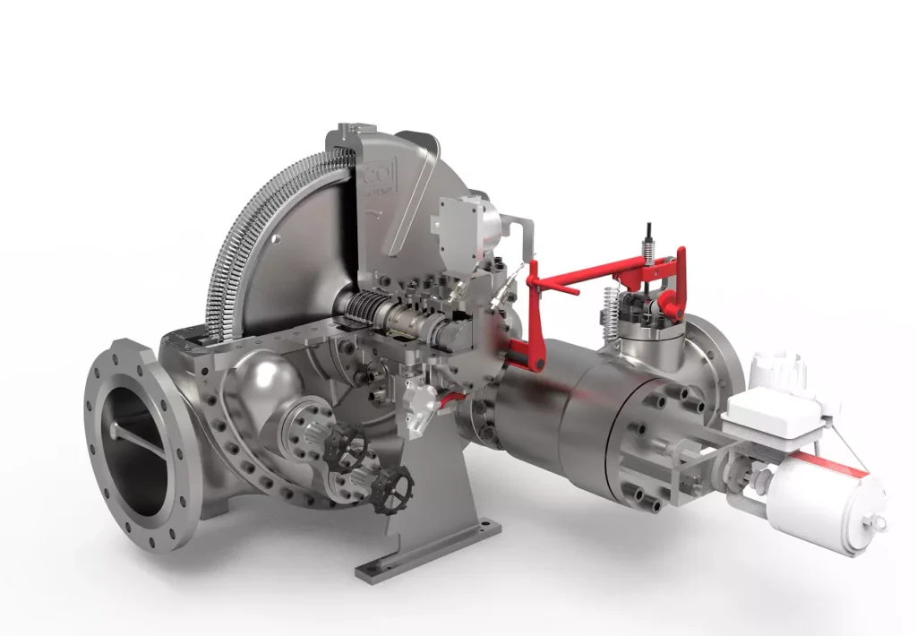
We design, manufacture and assembly Power Machines such as – diesel generators, electric motors, vibration motors, pumps, steam engines and steam turbines
EMS Power Machines is a global power engineering company, one of the five world leaders in the industry in terms of installed equipment. The companies included in the company have been operating in the energy market for more than 60 years.
EMS Power Machines manufactures steam turbines, gas turbines, hydroelectric turbines, generators, and other power equipment for thermal, nuclear, and hydroelectric power plants, as well as for various industries, transport, and marine energy.
EMS Power Machines is a major player in the global power industry, and its equipment is used in power plants all over the world. The company has a strong track record of innovation, and it is constantly developing new and improved technologies.
Here are some examples of Power Machines’ products and services:
- Steam turbines for thermal and nuclear power plants
- Gas turbines for combined cycle power plants and industrial applications
- Hydroelectric turbines for hydroelectric power plants
- Generators for all types of power plants
- Boilers for thermal power plants
- Condensers for thermal power plants
- Reheaters for thermal power plants
- Air preheaters for thermal power plants
- Feedwater pumps for thermal power plants
- Control systems for power plants
- Maintenance and repair services for power plants
EMS Power Machines is committed to providing its customers with high-quality products and services. The company has a strong reputation for reliability and innovation. Power Machines is a leading provider of power equipment and services, and it plays a vital role in the global power industry.
EMS Power Machines, which began in 1961 as a small factory of electric motors, has become a leading global supplier of electronic products for different segments. The search for excellence has resulted in the diversification of the business, adding to the electric motors products which provide from power generation to more efficient means of use.