Cogeneration (Combined Heat and Power – CHP) Plants: Cogeneration, also known as Combined Heat and Power (CHP), refers to power plants or energy systems that simultaneously produce electricity and useful thermal energy from a single source of fuel. Unlike conventional power generation, where a large portion of fuel energy is lost as waste heat during electricity production, cogeneration captures this heat and puts it to productive use, significantly increasing overall energy efficiency.
In a CHP plant, the primary fuel can be natural gas, biomass, coal, biogas, or even industrial waste gases. The system is designed so that when the fuel is burned in a prime mover—such as a gas turbine, steam turbine, or reciprocating engine—it generates electricity, and the byproduct heat, instead of being released into the atmosphere, is recovered through heat exchangers. This thermal energy can then be used for industrial processes, district heating, hot water supply, or even cooling through absorption chillers.
The main advantage of cogeneration plants lies in their high efficiency, often reaching 70–90% compared to the 30–40% typical of conventional power-only plants. This efficiency translates into reduced fuel consumption, lower operating costs, and significantly lower greenhouse gas emissions. In industrial settings, CHP systems are particularly valuable because they can provide both the electricity and the process heat required for manufacturing, making them a cornerstone of energy-intensive sectors such as chemicals, pulp and paper, food processing, and refineries. In urban applications, CHP units are often used for district energy systems, supplying electricity to the grid while providing centralized heating or cooling to entire neighborhoods.
Cogeneration can be implemented at various scales, from large utility-grade CHP plants that serve cities and industrial clusters, down to small modular units installed in hospitals, hotels, office complexes, or residential buildings. These distributed systems increase local energy resilience, reduce dependency on centralized grids, and provide stable energy at competitive costs.
From an environmental perspective, CHP supports decarbonization strategies, as it enables the integration of renewable fuels like biogas, biomass, or green hydrogen. Policymakers and energy planners are increasingly promoting cogeneration as part of sustainable energy infrastructure because it directly addresses the twin challenges of energy efficiency and emission reduction.
Cogeneration Plant Types
1. Gas Turbine CHP Plants
- A gas turbine burns natural gas or liquid fuels to produce electricity.
- The hot exhaust gases, instead of being released into the atmosphere, are recovered in a Heat Recovery Steam Generator (HRSG).
- The steam can be used for industrial processes, district heating, or to drive a steam turbine in a combined cycle.
- Common in medium to large-scale industrial facilities and district heating networks.
2. Steam Turbine CHP Plants
- Operates on the principle of a steam Rankine cycle.
- High-pressure steam is generated in a boiler and used to drive a steam turbine that produces electricity.
- After expansion, the lower-pressure steam is extracted and used for heating or industrial processes instead of being condensed.
- Widely applied in industries with high process heat demand such as pulp & paper, chemicals, and refineries.
3. Reciprocating Engine CHP Plants
- Uses large internal combustion engines (diesel engines, gas engines) as the prime mover.
- Produces electricity while the engine’s jacket water and exhaust gases are recovered as useful heat.
- Highly efficient in small to medium-scale applications.
- Popular in hospitals, hotels, commercial buildings, and smaller industrial sites due to quick start-up and load flexibility.
4. Combined Cycle CHP Plants
- Integrates gas turbines and steam turbines in a single plant.
- Gas turbine produces electricity and hot exhaust gases, which generate steam in an HRSG.
- Steam turbine produces additional electricity while also supplying heat.
- Very high efficiency (up to 80–90%) and commonly used in large-scale cogeneration facilities and utility power plants.
5. Microturbine CHP Plants
- Small-scale gas turbines (30–500 kW range) that generate electricity and recover exhaust heat.
- Suited for distributed generation in commercial buildings, residential complexes, and small industries.
- Compact, low-maintenance, and able to use a variety of fuels including natural gas, biogas, and liquid fuels.
6. Fuel Cell CHP Plants
- Fuel cells convert chemical energy (from hydrogen, natural gas, or biogas) directly into electricity through electrochemical reactions.
- The process also generates heat, which can be used for local heating or cooling.
- Very efficient, low emissions, and suitable for distributed energy in urban areas, though still relatively costly.
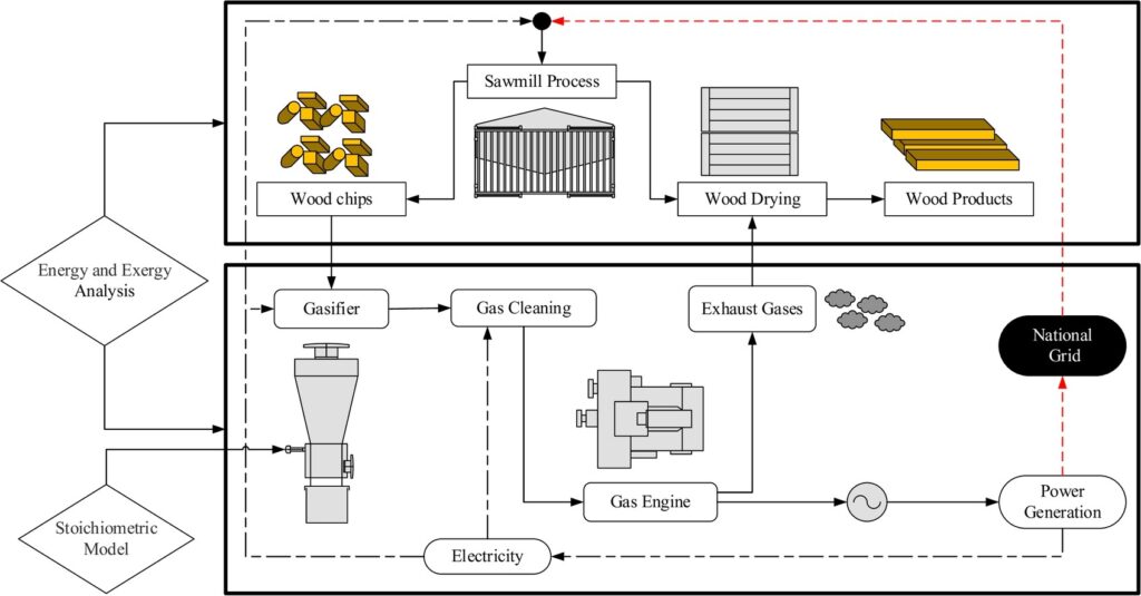
7. Biomass and Waste-Fired CHP Plants
- Uses solid biomass (wood chips, agricultural residues) or waste (municipal solid waste, industrial byproducts) as fuel.
- Generates steam for electricity production in a steam turbine and provides process heat or district heating.
- Strong sustainability benefits, as they replace fossil fuels and utilize renewable or waste resources.
Gas Turbine CHP Plants
Gas turbine cogeneration plants, often referred to as gas turbine CHP plants, represent one of the most efficient and widely used forms of combined heat and power production. These systems operate on the principle of utilizing a gas turbine as the prime mover to generate electricity while simultaneously capturing the high-temperature exhaust gases for productive use. In a conventional gas turbine power plant, the exhaust gases are discharged directly into the atmosphere, wasting a substantial portion of the fuel’s energy potential. However, in a CHP configuration, this waste heat is harnessed, typically through a heat recovery steam generator (HRSG), which significantly increases overall efficiency and provides valuable thermal energy for a wide range of applications.
The basic operating cycle of a gas turbine CHP plant follows the Brayton cycle. Fuel, usually natural gas but sometimes alternative fuels such as biogas, syngas, or liquid hydrocarbons, is mixed with compressed air and combusted in the combustion chamber. The resulting hot gases expand through the turbine blades, driving the turbine and producing mechanical energy, which is converted into electricity by the generator. The exhaust gases leaving the turbine can reach temperatures of 400–600 °C, a level of thermal energy that is more than sufficient to generate steam or hot water. By integrating a heat recovery steam generator, this energy is captured instead of wasted, producing high-pressure steam for industrial processes, district heating networks, or additional power generation when coupled with a steam turbine in a combined cycle configuration.
One of the primary advantages of gas turbine CHP plants is their high overall efficiency, which can reach 70–80% when both electricity and useful heat are accounted for. This is a remarkable improvement compared to conventional simple-cycle gas turbine power plants, which typically achieve only 30–40% efficiency. By reducing fuel consumption per unit of useful energy, cogeneration not only lowers operational costs but also significantly reduces greenhouse gas emissions and environmental impact. The high efficiency of gas turbine CHP systems makes them particularly attractive in regions where energy prices are high and sustainability targets are stringent.
Gas turbine CHP plants are highly flexible in terms of scale and application. They can be designed as large utility-scale installations providing both power to the grid and steam to industrial parks, or as medium-sized plants integrated into refineries, chemical complexes, and paper mills where large volumes of process steam are required. In urban settings, gas turbine CHP systems are often integrated into district heating and cooling networks, supplying entire residential and commercial areas with electricity, hot water, and even chilled water through absorption chillers. This distributed energy approach enhances energy resilience, reduces dependency on centralized grids, and provides a reliable supply of both power and heat close to the point of consumption.
Another important feature of gas turbine CHP plants is their fuel flexibility and operational reliability. Although natural gas remains the preferred fuel due to its high efficiency, low emissions, and availability, these systems can also operate on alternative fuels such as biogas, syngas from waste gasification, or liquid fuels in cases where natural gas supply is limited. This versatility allows operators to adapt to changing fuel markets and environmental regulations. Furthermore, gas turbines have relatively low maintenance requirements and long operational lifespans, making them a dependable choice for continuous power and heat generation.
In many cases, gas turbine CHP plants are designed as combined cycle cogeneration systems. In such a configuration, the gas turbine generates electricity and produces hot exhaust gases, which are directed into a heat recovery steam generator. The HRSG produces steam not only for industrial or district heating applications but also for a steam turbine that generates additional electricity. This combined cycle CHP approach can push overall plant efficiency even higher, often above 80%, while maximizing both the power output and the heat supply.
From an environmental and regulatory perspective, gas turbine CHP systems contribute significantly to carbon reduction goals. By optimizing the use of fuel and avoiding waste heat losses, they help industries and municipalities lower their carbon footprint while ensuring compliance with strict emission standards. Moreover, when integrated with renewable fuels such as biogas or hydrogen, gas turbine CHP plants can transition toward nearly carbon-neutral operation, aligning with global sustainability objectives. This makes them a key component in the energy transition strategies of many countries and corporations.
Economically, gas turbine CHP plants provide strong returns on investment by reducing energy costs and increasing efficiency. Industries that have both high electricity and thermal energy demands often achieve rapid payback periods, since CHP enables them to produce both utilities on-site instead of purchasing electricity from the grid and generating steam separately with boilers. In addition, many regions offer incentives, tax benefits, or preferential tariffs for cogeneration projects, further improving their financial attractiveness.
In conclusion, gas turbine CHP plants stand out as a proven, efficient, and versatile technology in the field of combined heat and power generation. They offer a unique balance of high electrical efficiency, reliable thermal energy production, operational flexibility, and environmental benefits. Whether applied at a large industrial complex, a utility-scale energy project, or an urban district heating system, gas turbine CHP provides a sustainable and economically viable pathway to optimize fuel use, reduce emissions, and enhance energy security.
Gas turbine CHP plants represent one of the most advanced and efficient solutions in the field of cogeneration, combining the proven performance of gas turbine technology with the ability to recover and utilize high-quality waste heat. At the core of this system is the gas turbine itself, which operates on the well-established Brayton cycle. Air is compressed, mixed with a fuel—most commonly natural gas—and combusted at high pressure, producing hot gases that expand through turbine blades and drive the generator to produce electricity. In a conventional power plant, the hot exhaust gases would be released into the atmosphere, carrying away a large amount of energy as waste. In a cogeneration setup, however, this thermal energy is recovered in a heat recovery steam generator, which transforms the exhaust gases into useful steam or hot water for a wide variety of industrial and commercial applications. This simple but highly effective modification changes the energy balance dramatically, raising the overall efficiency of the plant from the 30 to 40 percent typical of a simple-cycle turbine to levels that can exceed 70 or even 80 percent.
The impact of such efficiency improvements is significant from both an economic and environmental perspective. For industries and municipalities that operate energy-intensive processes or provide heating and cooling to large populations, the ability to use one fuel input to supply both electricity and heat results in substantial reductions in fuel consumption. This translates into lower energy costs and an increase in competitiveness, while also contributing to a considerable reduction in greenhouse gas emissions and pollutants. For operators in sectors such as petrochemicals, paper production, food processing, and district energy, gas turbine CHP plants have become an essential part of their energy infrastructure. The dual production of electricity and process heat allows them to meet internal energy demands while, in many cases, also exporting surplus power to the grid, generating additional revenue streams.
Another strength of gas turbine CHP plants lies in their flexibility of application. They can be built as large central stations supplying electricity to national grids while simultaneously delivering steam to industrial parks or city-wide heating networks. At the same time, they can also be designed in medium-scale configurations that fit seamlessly into the energy systems of refineries, chemical plants, or paper mills. In urban environments, gas turbine CHP plants are often integrated into district heating and cooling networks, where the captured heat is distributed to residential and commercial buildings, while absorption chillers can transform part of that heat into cooling energy for summer demand. This versatility has made them a cornerstone of modern energy strategies that prioritize efficiency, sustainability, and resilience.
Fuel flexibility adds another layer of attractiveness to gas turbine CHP systems. While natural gas remains the preferred fuel due to its clean combustion, high efficiency, and availability, gas turbines can also operate on a wide range of alternatives. These include liquid fuels, biogas from landfills or anaerobic digesters, syngas from biomass or waste gasification, and, increasingly, hydrogen or hydrogen-enriched fuels. This adaptability ensures that gas turbine CHP plants can evolve alongside energy markets and environmental regulations, allowing operators to reduce their dependency on a single fuel source and to prepare for a future in which low-carbon and renewable fuels will play a much larger role.
One of the most advanced configurations of gas turbine cogeneration is the combined cycle CHP plant, where the gas turbine not only generates electricity but also provides hot exhaust gases for a heat recovery steam generator. The steam from the HRSG can then be used to drive a steam turbine that produces additional electricity while also supplying steam for heating or industrial processes. This dual-turbine arrangement achieves the highest possible efficiency levels, making combined cycle CHP one of the most powerful and sustainable technologies available for large-scale energy production. Plants of this type are often deployed in utility-scale projects where both the electricity grid and local industries benefit from a highly efficient and reliable energy supply.
Reliability and operational stability are further advantages that make gas turbine CHP plants an attractive investment. Modern gas turbines are engineered for long service lifetimes, with robust designs that allow continuous operation for thousands of hours with relatively low maintenance compared to other prime movers. Their ability to ramp up and down relatively quickly also makes them valuable in power systems that need to balance fluctuating loads or integrate variable renewable energy sources such as wind and solar. By combining steady baseload production with flexible operation, gas turbine CHP plants contribute not only to energy efficiency but also to grid stability and security of supply.
From the perspective of environmental policy and climate goals, gas turbine CHP plants provide a practical and immediate pathway to reduce carbon emissions. By using fuel more efficiently and avoiding the waste of thermal energy, they achieve significant reductions in greenhouse gas output compared to separate heat and power generation. Furthermore, as they transition to renewable fuels such as biogas or hydrogen, they can move closer to carbon-neutral operation. This adaptability ensures that gas turbine CHP technology will continue to play an important role in the global energy transition, serving as a bridge between the current reliance on natural gas and the future vision of a low-carbon or carbon-free energy system.
Economically, gas turbine CHP plants often prove to be highly cost-effective investments, particularly in industries with steady and simultaneous demands for electricity and heat. By generating both on-site, operators reduce their dependency on grid electricity and separate boilers, lowering operational costs and improving overall energy management. In many cases, governments also provide incentives, tax benefits, or favorable regulatory frameworks to promote cogeneration, further enhancing the financial case. For industrial operators, the payback time for such systems is often relatively short, and the long-term savings in energy costs are substantial.
Ultimately, gas turbine CHP plants embody the key principles of modern energy systems: efficiency, sustainability, flexibility, and resilience. They transform what would otherwise be wasted heat into a valuable resource, delivering reliable electricity and useful thermal energy from the same fuel input. Their ability to adapt to different scales, fuels, and applications makes them an indispensable part of the energy landscape, whether in industrial zones, cities, or large-scale utilities. As energy systems around the world move toward cleaner, smarter, and more integrated solutions, gas turbine cogeneration plants will remain a critical technology that combines immediate benefits with long-term potential for a sustainable future.
Gas turbine cogeneration plants, also known as gas turbine CHP plants, are among the most efficient and versatile technologies available for producing electricity and useful heat simultaneously from a single fuel source. Their development has been driven by the need for energy systems that can deliver high efficiency, lower emissions, and reliable operation in a wide range of industrial, commercial, and municipal settings. At the core of this concept lies the gas turbine, a prime mover that operates on the well-established Brayton cycle. In this cycle, air is compressed, mixed with fuel, and combusted at high pressure, producing a high-temperature gas stream that expands through turbine blades to generate mechanical power, which is then converted into electricity by a generator. In a conventional simple-cycle power plant, the hot exhaust gases, which leave the turbine at temperatures often exceeding 400 to 600 °C, are released into the atmosphere, wasting a substantial fraction of the fuel’s energy potential. In contrast, gas turbine CHP systems are specifically designed to capture and utilize this otherwise wasted heat, typically through a heat recovery steam generator that produces steam or hot water. The steam can then be used directly in industrial processes, distributed through district heating networks, or even used to drive an additional steam turbine for further electricity generation.
The efficiency advantage of gas turbine CHP plants over conventional power generation is one of their defining characteristics. A simple-cycle gas turbine plant typically achieves an efficiency in the range of 30 to 40 percent, meaning that more than half of the fuel energy is lost as waste heat. When configured as a cogeneration system, the same plant can reach overall efficiencies of 70 to 80 percent, and in some cases even higher, because the thermal energy is put to productive use instead of being discarded. This improvement has major implications both for operating costs and for environmental performance. By extracting more useful energy from the same fuel input, operators reduce fuel consumption, which directly translates into financial savings. At the same time, carbon dioxide and other pollutant emissions per unit of useful energy are reduced, making gas turbine CHP a powerful tool for meeting climate and air quality objectives. This dual benefit of cost reduction and environmental performance explains why the technology has been adopted across many industries and cities worldwide.
The applications of gas turbine CHP plants are diverse and can be tailored to the specific needs of different users. In large industrial complexes such as refineries, petrochemical plants, paper mills, and food processing facilities, there is typically a constant demand for both electricity and process steam. A gas turbine CHP plant in such an environment can supply the facility with reliable power while providing the steam required for manufacturing operations, eliminating the need for separate boilers and purchased grid electricity. This integration not only reduces costs but also provides a high degree of energy independence and reliability, which is critical for industries where downtime is extremely costly. In urban environments, gas turbine CHP systems are frequently deployed as part of district heating and cooling networks. Here, the electricity is either used locally or fed into the grid, while the captured heat is distributed through pipelines to supply hot water or space heating to residential, commercial, and institutional buildings. During summer months, the same heat can be used to drive absorption chillers, producing chilled water for air conditioning and refrigeration, which further extends the versatility of the system. This capacity to serve multiple energy needs with a single plant makes cogeneration particularly valuable in densely populated areas where energy efficiency and sustainability are priorities.
Another important feature of gas turbine CHP plants is their scalability. They can be designed as large central stations with outputs of hundreds of megawatts, serving entire cities and industrial regions, or as medium-sized facilities dedicated to a single industrial plant. Advances in gas turbine technology have also made smaller modular units feasible, making cogeneration accessible even to smaller commercial complexes, hospitals, universities, or hotels. Regardless of scale, the underlying principle remains the same: maximize the value of fuel by simultaneously generating electricity and capturing usable heat. This adaptability ensures that gas turbine CHP can meet the requirements of many different users, from large-scale utilities to small distributed energy systems.
Fuel flexibility is another dimension that enhances the attractiveness of gas turbine CHP systems. While natural gas is by far the most commonly used fuel due to its clean combustion characteristics, widespread availability, and high energy content, gas turbines can be configured to run on alternative fuels. These include liquid fuels such as diesel or kerosene in areas where natural gas is not available, as well as renewable and low-carbon options such as biogas from landfills or anaerobic digestion, syngas produced from biomass or municipal waste gasification, and increasingly hydrogen or hydrogen-enriched natural gas blends. The ability to integrate renewable or waste-derived fuels makes gas turbine CHP plants a valuable component of sustainable energy strategies, as they not only reduce reliance on fossil fuels but also enable the utilization of resources that might otherwise be wasted. Looking toward the future, the potential to operate on green hydrogen positions gas turbine CHP as a key transitional technology on the path to carbon-neutral energy systems.
One of the most advanced configurations of gas turbine cogeneration is the combined cycle CHP plant. In this arrangement, the hot exhaust gases from the gas turbine are not only used to generate steam for industrial use or district heating but are also directed to a steam turbine to produce additional electricity. This dual-turbine approach achieves some of the highest efficiencies of any fossil-fuel-based energy technology, with overall efficiencies often surpassing 80 percent. Combined cycle CHP plants are commonly deployed in utility-scale projects where large amounts of electricity are required alongside significant thermal demand, such as in industrial hubs or metropolitan areas with extensive district heating networks. These plants represent the pinnacle of gas turbine cogeneration technology, combining the advantages of large-scale electricity generation with the fuel-saving benefits of cogeneration.
From the perspective of energy policy and environmental regulation, gas turbine CHP plants play an important role in helping industries and municipalities meet increasingly strict efficiency and emissions standards. By extracting the maximum possible value from each unit of fuel, they allow operators to significantly reduce carbon dioxide emissions per megawatt-hour of energy delivered. This is particularly important as governments around the world push for decarbonization of energy systems while still maintaining reliable supply. Moreover, the ability to integrate renewable fuels into gas turbine CHP systems provides a pathway toward even lower emissions in the future. For example, plants that today operate primarily on natural gas can be progressively adapted to run on biogas or hydrogen, thus extending their usefulness in a decarbonizing energy market. This adaptability ensures that investments in gas turbine CHP remain relevant for decades, even as energy systems evolve.
Reliability and operational stability are additional advantages of gas turbine CHP plants. Modern turbines are designed for long service lifetimes, capable of running continuously for thousands of operating hours with relatively modest maintenance requirements compared to other prime movers. Their ability to start quickly and adjust output makes them particularly useful in systems where load demands fluctuate or where variable renewable energy sources such as wind and solar need to be balanced. In such contexts, gas turbine CHP plants not only provide efficient heat and power but also contribute to overall grid stability and energy security. This combination of efficiency, flexibility, and reliability makes them indispensable in many modern energy systems.
Economically, gas turbine CHP plants often deliver strong returns on investment. For industries with constant demand for heat and power, the savings generated by reducing grid electricity purchases and boiler fuel consumption can result in relatively short payback periods. In many regions, additional financial benefits are available in the form of tax incentives, grants, or preferential tariffs for cogeneration projects, all designed to encourage adoption of more efficient and sustainable energy systems. Beyond direct financial returns, the investment in CHP also strengthens competitiveness by improving energy security, reducing exposure to volatile energy markets, and demonstrating environmental responsibility, which is increasingly important for corporate image and compliance with sustainability standards.
In the broader context of the global energy transition, gas turbine CHP plants serve as a crucial bridging technology. They combine the reliability and scalability of conventional fossil-fuel-based systems with the efficiency and adaptability required in a low-carbon future. By using existing fuels more efficiently, they deliver immediate environmental and economic benefits. By being able to integrate renewable fuels such as biogas or hydrogen, they ensure compatibility with long-term decarbonization goals. This unique combination makes gas turbine CHP plants a central component of sustainable energy strategies in many parts of the world, from industrial zones in Asia and Europe to urban energy systems in North America and emerging markets.
Ultimately, gas turbine cogeneration plants embody the essential principles of modern energy engineering: efficiency, sustainability, resilience, and adaptability. They transform what would otherwise be wasted heat into a valuable resource, creating a balanced supply of electricity and thermal energy from the same fuel input. Their ability to scale from medium-sized industrial plants to large utility projects, to operate on a variety of fuels, and to integrate with district energy systems ensures their continued relevance in a rapidly changing energy landscape. As the world moves toward cleaner, smarter, and more integrated energy solutions, gas turbine CHP technology stands out as a proven, dependable, and forward-looking option that meets the pressing demands of today while preparing for the challenges of tomorrow.
Gas turbine cogeneration plants, or gas turbine CHP plants, are today considered one of the most effective and reliable solutions for meeting the dual needs of electricity and heat in a wide range of applications. Their strength lies in the combination of proven turbine technology with the principle of combined heat and power production, which allows a single fuel input to be converted into multiple useful forms of energy. By recovering the high-temperature exhaust gases produced during turbine operation and putting them to productive use, these plants maximize fuel utilization and minimize waste, achieving efficiency levels that are significantly higher than conventional power generation systems. For industries and municipalities alike, this translates into lower energy costs, reduced greenhouse gas emissions, and enhanced energy security.
The working principle of a gas turbine CHP plant begins with the Brayton cycle. In this cycle, ambient air is drawn into a compressor, where it is pressurized and directed into a combustion chamber. Fuel, most commonly natural gas but potentially other alternatives such as biogas, syngas, or liquid fuels, is injected and combusted with the compressed air, producing high-temperature, high-pressure gases. These gases expand through the turbine section, driving the blades connected to a generator that produces electricity. In a simple-cycle turbine, the hot exhaust gases would be released into the atmosphere, carrying away a large share of the energy content. In cogeneration mode, however, the exhaust gases are directed to a heat recovery steam generator (HRSG), where their energy is used to produce steam or hot water. This steam can serve industrial processes, district heating, or additional power generation if a steam turbine is incorporated into the cycle. In this way, gas turbine CHP plants achieve a synergy that fundamentally alters the efficiency profile of power generation.
The efficiency gains from cogeneration are striking. While a typical simple-cycle gas turbine has an electrical efficiency of around 35 percent, the integration of heat recovery increases the total useful efficiency to 70, 80, or even 85 percent in optimized systems. This dramatic increase means that for every unit of fuel consumed, nearly twice as much useful energy is obtained compared to conventional configurations. For industrial operators, this reduction in fuel consumption per unit of output translates directly into lower operating expenses. For policymakers and society, it means fewer greenhouse gas emissions and pollutants for the same amount of energy service, supporting both climate goals and public health objectives. In many countries, regulatory frameworks recognize these benefits by offering incentives, tax credits, or favorable tariffs to promote CHP deployment, further enhancing its attractiveness.
Industrial applications are among the most important use cases for gas turbine CHP plants. Industries such as petrochemicals, refining, pulp and paper, textiles, and food processing have simultaneous and continuous demands for both electricity and process steam. In these sectors, a gas turbine CHP plant can provide the electricity needed to power motors, drives, and lighting, while also supplying the high-pressure steam required for manufacturing processes, drying, or chemical reactions. The elimination of separate boilers and external grid purchases not only reduces costs but also enhances reliability, as the facility becomes largely self-sufficient in energy. In refineries, for example, cogeneration units often supply both internal energy needs and surplus electricity to the grid, improving the facility’s overall economics while supporting local energy supply.
Municipal and district energy systems represent another area where gas turbine CHP plants have demonstrated great value. In cities across Europe, Asia, and North America, cogeneration plants are integrated into district heating networks, supplying hot water and steam through pipelines to residential, commercial, and institutional buildings. In such systems, the electricity generated is either used locally or sold to the grid, while the recovered heat provides a low-cost and sustainable alternative to individual heating solutions. In warmer climates or during summer months, the recovered heat can be used in absorption chillers to produce chilled water for air conditioning, creating a district cooling network. This multi-functional energy service model demonstrates the versatility of gas turbine CHP and its ability to adapt to seasonal variations in demand. By serving as centralized hubs for efficient energy production, these plants contribute to reducing overall urban emissions, improving air quality, and lowering energy costs for end users.
The scale of gas turbine CHP plants can vary widely, which makes them suitable for different operational contexts. Large-scale plants with outputs in the hundreds of megawatts are used by utilities to serve cities or industrial regions, often operating as combined cycle plants that integrate both gas and steam turbines for maximum efficiency. Medium-sized plants are commonly found in large factories, industrial parks, and refineries, where they can provide tens of megawatts of power and substantial amounts of process steam. Smaller modular gas turbine CHP units are increasingly being used in commercial complexes, universities, hospitals, and hotels, where they provide reliable electricity alongside heating and cooling. This scalability ensures that gas turbine CHP can be tailored to match specific energy demand profiles, avoiding overcapacity and ensuring optimal efficiency.
One of the most advanced configurations of gas turbine CHP is the combined cycle cogeneration system. In this setup, the gas turbine produces electricity while the exhaust gases are directed into a heat recovery steam generator. The HRSG then produces steam that can either be used for industrial processes or sent to a steam turbine for additional electricity generation. The integration of both turbines results in higher electrical output while still providing thermal energy to users. Combined cycle CHP plants often achieve efficiencies exceeding 80 percent, making them among the most efficient fossil-fuel-based energy systems currently available. Such plants are frequently deployed in areas with high and continuous demand for both power and heat, as their efficiency and reliability make them ideal for long-term, large-scale operation.
Fuel flexibility is an increasingly important consideration in the deployment of gas turbine CHP plants. Natural gas remains the dominant fuel due to its high energy content, relatively low emissions, and established infrastructure. However, the ability of gas turbines to operate on alternative fuels is expanding their role in sustainable energy strategies. Biogas from landfills or anaerobic digestion provides a renewable substitute, while syngas from biomass or municipal waste gasification offers another pathway to reduce fossil fuel dependence. In addition, hydrogen is emerging as a key fuel of the future, and turbine manufacturers are investing heavily in developing models that can operate on hydrogen blends or eventually pure hydrogen. This capability positions gas turbine CHP plants as a transitional technology that not only delivers immediate efficiency and emissions benefits but also has the potential to operate with zero-carbon fuels in the future.
Reliability and operational flexibility are other reasons why gas turbine CHP plants are widely adopted. Gas turbines are robust machines designed for continuous operation, with long service intervals and proven durability. Their ability to ramp output up or down makes them valuable in modern power systems where renewable energy sources like solar and wind introduce variability. In such systems, gas turbine CHP plants can provide a steady supply of both electricity and heat while also helping balance the grid, ensuring stability and preventing disruptions. In facilities where energy reliability is critical, such as hospitals or data centers, the ability to maintain uninterrupted power and thermal supply is a decisive advantage.
From an economic perspective, gas turbine CHP plants often offer favorable investment returns, especially in applications with continuous heat and power demand. By displacing the need to purchase electricity from the grid and reducing or eliminating boiler fuel consumption, they lower operating costs significantly. Many projects also benefit from the ability to export surplus electricity, creating an additional revenue stream. The payback period for gas turbine CHP investments is often relatively short, particularly when government incentives or preferential tariffs are available. Beyond the financial returns, CHP systems enhance competitiveness by reducing exposure to energy price volatility and demonstrating environmental responsibility, which can improve corporate reputation and compliance with sustainability standards.
In the broader context of global energy transitions, gas turbine CHP plants are positioned as a critical bridging technology. They combine the advantages of conventional fuel reliability with the efficiencies needed in modern sustainable energy strategies. By using fuel more efficiently, they immediately reduce emissions and energy costs. By being capable of integrating renewable and low-carbon fuels such as biogas, syngas, or hydrogen, they offer long-term compatibility with decarbonization goals. This dual capacity makes them highly relevant to both current and future energy systems. Policymakers increasingly view CHP as a cornerstone technology for sustainable energy infrastructure, recognizing its potential to reduce carbon footprints while ensuring reliable and affordable energy supply.
Ultimately, gas turbine cogeneration plants embody the essential characteristics demanded of modern energy solutions: efficiency, adaptability, resilience, and environmental performance. They transform waste into value, producing electricity and thermal energy in a balanced and optimized manner. Their ability to operate at different scales, on different fuels, and in different contexts ensures their continued relevance, whether serving a single industrial plant, a large metropolitan district energy system, or an entire industrialized region. As industries and cities pursue greater efficiency and lower emissions, gas turbine CHP will remain a cornerstone technology, providing a proven, dependable, and future-ready approach to meeting the world’s growing energy needs.
The main parts of a Gas Turbine CHP Plant can be described in terms of the major components that allow it to generate both electricity and useful heat efficiently:
1. Air Intake and Compression System
- Ambient air is drawn into the system through an air intake filter to remove dust and particles.
- A compressor then pressurizes the air, increasing its pressure and temperature before it enters the combustion chamber.
- The compressor is usually an axial or centrifugal type and is mechanically linked to the turbine shaft.
2. Combustion Chamber (Combustor)
- Fuel, most commonly natural gas but sometimes biogas, syngas, hydrogen, or liquid fuels, is injected into the compressed air stream.
- The mixture is ignited in the combustion chamber, producing high-temperature, high-pressure gases.
- Advanced combustors are designed to minimize NOx and CO₂ emissions while ensuring stable combustion.
3. Gas Turbine
- The hot gases expand through the turbine section, driving turbine blades connected to a rotating shaft.
- This shaft powers both the compressor (at the front of the machine) and the generator (for electricity production).
- The efficiency and output of the turbine depend on the design and the inlet temperature of the gases.
4. Electric Generator
- The turbine shaft is mechanically coupled to an alternator that converts mechanical energy into electricity.
- Electricity can be used locally or exported to the grid, depending on the plant configuration.
- A control system ensures stable voltage and frequency output.
5. Exhaust Gas System
- After passing through the turbine, the exhaust gases still carry a large amount of heat energy (400–600 °C).
- Instead of being released to the atmosphere, these gases are directed to a heat recovery system.
6. Heat Recovery Steam Generator (HRSG)
- The HRSG is the key cogeneration component.
- It captures heat from the turbine exhaust gases and converts it into steam or hot water.
- The steam can be used directly in industrial processes, supplied to district heating networks, or used to power a steam turbine in a combined cycle CHP system.
7. Steam Turbine (in Combined Cycle CHP)
- In larger CHP plants, the steam from the HRSG is directed into a steam turbine.
- This turbine produces additional electricity while still allowing extraction of steam for heating or industrial use.
- This combined arrangement pushes overall efficiency to very high levels.
8. Cooling and Condensate Systems
- If steam is not fully utilized for heating, part of it may be condensed in a condenser and recirculated as feedwater.
- Cooling systems (air-cooled or water-cooled) ensure stable operation and maintain thermal balance.
9. Heat Distribution System
- The recovered heat is delivered to industrial processes (high-pressure steam, hot air, hot water).
- In urban setups, it is distributed via district heating pipelines to residential and commercial buildings.
- In some cases, heat drives absorption chillers for district cooling.
10. Control and Monitoring Systems
- Advanced automation and control systems manage fuel flow, turbine operation, generator synchronization, and HRSG performance.
- They optimize efficiency, ensure safety, and maintain emissions within regulatory limits.
- Remote monitoring is often used for diagnostics and predictive maintenance.
Air Intake and Compression System
The air intake and compression system of a gas turbine CHP plant plays a fundamental role in the overall performance and efficiency of the installation, since it is the first step of the thermodynamic process that later makes electricity and heat generation possible. Ambient air, which naturally contains varying amounts of dust, dirt, humidity, and even small particles depending on the location, must be carefully managed before it enters the turbine. For this reason, the air intake system is equipped with large filter units designed to remove contaminants and ensure that the turbine receives a continuous supply of clean air. Any impurity that enters the compressor section can cause erosion, fouling, or corrosion of the blades, which not only reduces efficiency but can also shorten the life of the turbine. Therefore, the intake filters are engineered to deliver high air purity while maintaining low pressure drop, since excessive resistance at this stage would reduce the overall efficiency of the plant.
Once the air has been drawn in and filtered, it enters the compressor, which is one of the most energy-intensive components of the gas turbine system. The compressor’s task is to raise the pressure and temperature of the incoming air so that it can mix efficiently with the fuel and combust under controlled high-pressure conditions in the combustion chamber. Most gas turbines use axial-flow compressors, which consist of multiple stages of rotating and stationary blades that progressively compress the air as it flows through the machine. Some smaller turbines may employ centrifugal compressors, which are simpler in design but less common in large-scale CHP applications. In an axial compressor, each stage adds a modest increase in pressure, but by the time the air passes through a series of 10 to 20 stages, the overall pressure ratio becomes significant, often reaching 10:1, 15:1, or even higher in advanced turbines. The quality of this compression process is critical, since the efficiency of combustion and the power output of the turbine depend heavily on the pressure and temperature of the air entering the combustor.
The compressor is mechanically coupled to the turbine shaft, meaning that part of the energy generated in the turbine section is used to drive the compressor. This internal energy demand is substantial, sometimes consuming more than half of the turbine’s gross power output, which highlights how essential an efficient compressor design is for the viability of the entire CHP system. Despite this, the compressor’s contribution to overall plant performance is immense, because the higher the pressure ratio achieved at this stage, the more efficient the combustion process becomes, and the greater the potential for high turbine output and higher exhaust temperatures that feed the downstream heat recovery steam generator.
Another important aspect of the air intake and compression system in CHP plants is its adaptability to ambient conditions. Since turbines often operate in outdoor environments, variations in temperature, humidity, and air density can significantly affect performance. For example, during hot summer days, the density of air decreases, leading to lower mass flow rates through the compressor and, consequently, reduced power output. To counter this, many plants incorporate inlet cooling technologies such as evaporative coolers, fogging systems, or even mechanical chillers that lower the temperature of the incoming air, thereby increasing its density and improving the overall efficiency of the system. Similarly, in cold climates, heating systems may be used to prevent icing at the air intake, which could otherwise damage filters and compressor blades.
Noise reduction is another consideration in the design of the air intake system. As large volumes of air are drawn into the turbine at high velocity, significant noise is generated. To address this, intake silencers and acoustic enclosures are often employed, particularly in urban cogeneration plants where noise levels must remain within regulatory limits. These acoustic treatments ensure that the plant can operate reliably without disturbing nearby communities, which is an important factor in district heating or distributed generation projects.
Maintenance and monitoring of the air intake and compression system are also essential for ensuring long-term reliability. The filters in the intake system must be inspected and replaced regularly to prevent clogging, which would otherwise increase pressure drop and reduce efficiency. The compressor itself must be kept free from deposits, as fouling can degrade aerodynamic performance and increase fuel consumption. In many CHP plants, online or offline washing of the compressor is conducted to remove accumulated dirt and restore performance. Advanced monitoring systems track vibration, temperature, and pressure at different stages of the compressor, providing operators with valuable data to detect early signs of wear or imbalance. Predictive maintenance based on these diagnostics minimizes downtime and extends the operational life of the machine.
In the broader context of CHP, the air intake and compression system indirectly influences not only the turbine’s electrical output but also the quality of the exhaust gases supplied to the heat recovery steam generator. The temperature and mass flow rate of the exhaust gases are directly related to how efficiently the compressor operates and how much fuel can be combusted in the chamber. This, in turn, determines how much useful heat can be captured for district heating, industrial processes, or additional steam turbine generation. A poorly performing compressor would lead to lower exhaust temperatures and reduced thermal recovery, undermining the very concept of cogeneration.
Thus, the air intake and compression system is far more than just the front-end of a gas turbine; it is a cornerstone of the plant’s overall efficiency, reliability, and environmental performance. By ensuring that the turbine always receives clean, properly conditioned, and efficiently compressed air, this system maximizes the effectiveness of the combustion process, optimizes fuel utilization, and supports the generation of both electricity and valuable heat. Whether in a large industrial CHP installation supplying steam to a refinery or in an urban district heating project providing power and hot water to thousands of homes, the air intake and compression system sets the stage for the successful operation of the entire cogeneration process.
The combustion chamber of a gas turbine CHP plant is the heart of the entire energy conversion process, where the compressed air from the compressor meets the fuel and undergoes rapid chemical reactions to release large amounts of energy. This component must perform an extremely delicate balance: it has to mix fuel and high-pressure air in the correct proportions, ensure stable and complete combustion, maintain high flame temperatures, and at the same time keep emissions within strict environmental limits. In cogeneration plants, the performance of the combustion chamber directly determines both the electrical efficiency of the turbine and the temperature of the exhaust gases that later provide useful heat in the heat recovery steam generator. For this reason, its design is one of the most technologically advanced areas of gas turbine engineering.
When compressed air enters the combustion chamber, it is already at elevated pressure and temperature due to the work of the compressor. Fuel is injected into this stream through specially designed nozzles that promote fine atomization and mixing. The most common fuel in CHP applications is natural gas, valued for its high calorific value, clean combustion, and widespread availability. However, combustion chambers can also be adapted to burn alternative fuels such as biogas, syngas from waste gasification, hydrogen blends, or liquid fuels like diesel and kerosene. This versatility allows CHP plants to adapt to local fuel markets, regulations, and sustainability goals. Ignition of the mixture is initiated by spark plugs or pilot flames, after which the flame becomes self-sustaining as long as the fuel and air flow are maintained.
The high-pressure combustion releases enormous amounts of thermal energy, raising the temperature of the gases to over 1,000 °C or more, depending on turbine design. These hot gases then expand toward the turbine section, where their energy is converted into mechanical power. But the combustion chamber is more than just a space for burning fuel—it must also protect the surrounding structure and materials from these extreme conditions. To achieve this, advanced cooling techniques are used, such as film cooling, where a thin layer of cooler air is bled from the compressor and directed along the inner walls of the chamber to form a protective barrier. This prevents the metal surfaces from overheating and ensures the chamber’s longevity even under continuous operation.
Emissions control is another critical function of the combustion chamber in a CHP plant. High flame temperatures tend to favor the formation of nitrogen oxides (NOx), which are harmful pollutants subject to stringent environmental regulations. To mitigate this, modern combustion systems employ dry low-NOx (DLN) technology, where the fuel and air are premixed before ignition to produce a lean mixture that burns at lower peak temperatures. This reduces NOx formation while maintaining stable combustion. In some cases, water or steam injection is used to further reduce flame temperature and control emissions, though this method is less common in modern designs due to efficiency considerations. The ability to deliver clean combustion is especially important in urban cogeneration plants, where CHP installations often operate close to residential or commercial areas.
The stability of the combustion process also plays a decisive role in the reliability of a CHP plant. Any instability, such as flame oscillations or incomplete combustion, can cause vibrations, damage to turbine components, or efficiency losses. Therefore, combustion chambers are designed to promote a uniform flame, avoid hot spots, and ensure consistent mixing across the full range of operating conditions. Since CHP plants often need to respond flexibly to variations in heat and power demand, the combustion system must remain stable and efficient even during load changes or when running on different fuel blends. Advanced monitoring systems track pressure, temperature, and emissions in real time, allowing operators to fine-tune the combustion process and maintain optimal performance.
From the perspective of cogeneration, the combustion chamber not only initiates the conversion of fuel energy into mechanical work but also sets the stage for the quality of thermal energy that can be recovered. The temperature of the exhaust gases leaving the turbine depends heavily on how combustion is managed, and this exhaust heat is the very resource that CHP plants are designed to capture and use productively. A combustion chamber that achieves high efficiency and clean burning ensures that the exhaust gases retain both high energy content and low pollutant levels, making them ideal for downstream recovery in the heat recovery steam generator. In contrast, poorly managed combustion would not only waste fuel and increase emissions but also reduce the amount of useful heat available for industrial processes or district heating systems.
Economically, the combustion chamber contributes to the fuel efficiency that underpins the financial viability of CHP projects. By enabling complete and optimized combustion, it maximizes the energy extracted from every unit of fuel, reducing operating costs and improving payback periods. Since fuel is the largest cost factor in any CHP plant, this efficiency directly translates into savings and makes cogeneration more competitive compared to separate production of electricity and heat. Additionally, the capability to operate on renewable or low-carbon fuels provides a pathway toward sustainable operation and compliance with future environmental standards, enhancing the long-term value of the investment.
In practical terms, the combustion chamber embodies the transformation from chemical energy to thermal energy, which is the foundation of the gas turbine CHP process. It combines advanced engineering, materials science, fluid dynamics, and environmental technology in a compact unit that must perform reliably over thousands of operating hours. The heat it generates not only drives the turbine to produce electricity but also enriches the exhaust flow with valuable energy that CHP plants harness to supply steam, hot water, or even chilled water through absorption cooling. In this way, the combustion chamber is central to the dual mission of cogeneration: to produce electricity efficiently and to make full use of the heat that conventional power plants would otherwise waste.
The gas turbine itself is the central rotating machine of the cogeneration plant and the component where the thermal energy generated in the combustion chamber is transformed into mechanical power. When the high-pressure, high-temperature gases leave the combustor, they expand rapidly through a series of turbine stages equipped with precisely engineered blades. These blades are arranged in alternating rows of stationary and rotating elements, with the stationary vanes directing the flow of gases at the optimal angle onto the rotating blades. As the gases expand and lose pressure, they transfer their kinetic and thermal energy to the turbine shaft, setting it into motion. This rotating shaft is directly coupled to both the compressor at the front of the turbine and the generator that produces electricity, which means the turbine is at the core of the entire cycle. Its efficiency and reliability determine the plant’s performance, making it one of the most critical and technically advanced components in a CHP system.
The materials used in turbine blades and rotors must withstand extreme operating conditions, as temperatures in the turbine can exceed 1,200 °C, with pressures dropping sharply as the gases expand. To cope with these stresses, turbine blades are manufactured from high-performance alloys, often nickel-based, and are equipped with complex internal cooling passages that allow a flow of cooler air, bled from the compressor, to circulate inside them. In some designs, the blade surfaces are coated with thermal barrier materials that protect them against heat and oxidation. These technologies make it possible for the turbine to operate reliably for thousands of hours without failure, even under demanding cogeneration conditions where the plant may run continuously to supply both electricity and thermal energy to users.
The mechanical energy produced by the turbine shaft is partially consumed by the compressor, which can require more than half of the shaft power to operate. The remaining portion is used to drive the electric generator, which converts the rotational energy into electrical output. The balance between compressor demand and turbine output is critical, since only the net power delivered to the generator is available for external use. In a CHP configuration, however, the importance of the turbine goes beyond just the electricity it generates. The exhaust gases that leave the turbine still carry a large amount of usable thermal energy at temperatures typically between 400 and 600 °C. This hot stream is what makes cogeneration possible, since instead of releasing it to the atmosphere, the system directs it to a heat recovery steam generator to produce steam or hot water for heating or industrial use.
Operational flexibility is another defining feature of gas turbines in CHP plants. They can be designed to start up relatively quickly compared to steam turbines, allowing them to respond to variations in electricity and heat demand. This is particularly valuable in urban district heating applications, where daily and seasonal fluctuations in demand can be significant. The turbine can be operated at part load when demand is low, though efficiency decreases somewhat under these conditions. Modern control systems help mitigate this by optimizing fuel flow, combustion stability, and turbine blade cooling, ensuring reliable performance across a wide range of operating modes.
The reliability of the gas turbine is vital for the overall success of cogeneration projects. Since many CHP plants supply not only electricity but also essential thermal energy to industrial processes or entire heating networks, interruptions in turbine operation can have serious consequences. To prevent unexpected downtime, turbines are equipped with sophisticated monitoring systems that track temperature distributions, vibration levels, rotor speeds, and pressure variations. Any anomaly detected can trigger alerts or automatic protective actions, ensuring safe and continuous operation. Maintenance strategies are usually based on a combination of scheduled inspections and predictive diagnostics, with critical components such as blades, bearings, and seals being checked and replaced at defined intervals to extend the plant’s lifespan.
From an efficiency standpoint, the gas turbine contributes significantly to the overall performance of a CHP plant. Simple-cycle gas turbines operating alone usually reach electrical efficiencies of around 30–40%, but when the exhaust heat is recovered and used in cogeneration, the total system efficiency can reach 70–80% or even higher. This means that the turbine, while not perfect on its own, becomes a highly effective tool for maximizing fuel utilization when integrated into a CHP arrangement. The high temperature of the exhaust gases is a direct result of the turbine’s expansion process, and this feature is precisely what distinguishes cogeneration from conventional electricity-only generation.
Environmentally, the turbine section benefits from the clean combustion achieved in the combustor, ensuring that the exhaust gases are suitable for heat recovery without producing excessive levels of pollutants. With the increasing interest in sustainable fuels, turbines are also being adapted to operate with blends of hydrogen and natural gas, or even pure hydrogen in the future. This would make gas turbine CHP plants a bridge technology between today’s natural gas-based systems and tomorrow’s low-carbon or carbon-neutral energy solutions.
Economically, the gas turbine is the engine that makes cogeneration financially attractive. Its ability to generate both electricity for local use or sale to the grid and exhaust heat for steam or hot water reduces the total cost of energy production. This dual output improves return on investment and shortens payback periods, especially for industries with high and continuous demand for both power and process heat. In addition, the long operational life and proven reliability of modern gas turbines make them a secure investment for companies and municipalities seeking stable energy supply.
In summary, the gas turbine is the centerpiece of a CHP plant, converting the chemical energy of fuel into mechanical power and providing high-temperature exhaust gases that enable efficient heat recovery. It embodies decades of engineering innovation in materials, aerodynamics, cooling technologies, and emissions control, all aimed at delivering maximum efficiency, flexibility, and reliability. In the context of cogeneration, its role extends beyond simple electricity generation to becoming a foundation for integrated energy systems that simultaneously meet the electrical, thermal, and environmental needs of modern society.
Combustion Chamber (Combustor)
The combustion chamber, or combustor, in a gas turbine CHP plant is the critical component where the chemical energy of the fuel is transformed into the high-temperature, high-pressure gases that drive the turbine and ultimately enable both electricity and heat production. This chamber must perform a complex and delicate task: it has to mix compressed air with fuel in precise proportions, ignite it safely and efficiently, sustain stable combustion under variable load conditions, and simultaneously control the formation of pollutants such as nitrogen oxides (NOx) and carbon monoxide. The design of the combustion chamber is therefore central not only to the operational efficiency of the turbine but also to the quality and temperature of the exhaust gases that feed the heat recovery steam generator, which is the heart of the cogeneration aspect of the plant.
When the compressed air from the turbine compressor enters the combustion chamber, it is at elevated pressure and temperature, ready to support efficient fuel combustion. Fuel, typically natural gas for its high energy content, low pollutant emissions, and availability, is injected through precision-engineered nozzles that ensure fine atomization and thorough mixing with the air. In addition to natural gas, many modern CHP plants are designed to operate on alternative fuels such as biogas, syngas produced from biomass or waste gasification, hydrogen-enriched fuels, or even liquid fuels such as diesel or kerosene. This fuel flexibility is crucial for adapting plants to local energy markets, renewable energy integration, and long-term decarbonization strategies. Ignition is initiated through spark plugs or pilot flames, after which the combustion becomes self-sustaining as long as fuel and air are continuously supplied.
The combustion process produces gases with extremely high temperatures, often exceeding 1,000 °C, and high pressure. These gases are then directed toward the turbine section to produce mechanical power. The chamber itself, however, must withstand these extreme conditions without damage. To achieve this, advanced cooling techniques are employed, including film cooling, where a small portion of air from the compressor flows along the inner walls to protect them from overheating, and the use of thermal barrier coatings on metallic components to resist high temperatures and oxidation. These design features ensure durability and reliability even under continuous operation, which is essential for plants that operate day and night to provide electricity and process heat.
Emissions control is a key aspect of combustor design. High flame temperatures naturally lead to the formation of nitrogen oxides, which are regulated pollutants. Modern combustion systems employ dry low-NOx (DLN) technology, where the fuel and air are premixed to create a lean combustion mixture that burns at lower temperatures while still providing complete fuel conversion. In some systems, water or steam injection is used to reduce flame temperature and further control emissions, though this is less common in newer designs due to efficiency losses. The result is a combustion process that maintains high thermal output while minimizing harmful emissions, an important requirement for urban CHP installations or industrial sites operating under strict environmental regulations.
The stability of combustion is also critical for turbine and plant reliability. Any fluctuations or instabilities in the flame can lead to vibrations, uneven heating, or incomplete combustion, which could reduce efficiency or even damage turbine components. Combustion chambers are therefore carefully designed to ensure uniform flame distribution, avoid hot spots, and maintain performance over a wide range of operating conditions, including partial loads or varying fuel compositions. Advanced monitoring systems track parameters such as pressure, temperature, and emissions, allowing real-time adjustments to optimize combustion and protect turbine integrity.
The performance of the combustion chamber directly impacts the cogeneration efficiency of the plant. The temperature and flow rate of the exhaust gases leaving the turbine are a function of how well combustion is carried out. High-temperature, consistent exhaust gases ensure maximum energy recovery in the heat recovery steam generator, which in turn produces steam or hot water for industrial processes, district heating, or even additional electricity generation in a combined cycle setup. Poor combustion, in contrast, would not only waste fuel but also limit the amount of usable heat, undermining the economic and environmental benefits of cogeneration.
Economically, an efficient combustion chamber maximizes fuel utilization, reducing operating costs and improving payback periods for the CHP investment. By ensuring complete and optimized combustion, every unit of fuel contributes to electricity production and usable heat, enhancing the financial viability of the plant. Moreover, the capability to burn renewable or low-carbon fuels adds long-term value, allowing operators to comply with evolving environmental regulations and to participate in sustainable energy initiatives.
In practical terms, the combustion chamber embodies the transformation of chemical energy into thermal energy, which is essential for both the mechanical power generation and the thermal output that define cogeneration. It integrates advanced engineering, fluid dynamics, material science, and emissions control into a compact, high-performance unit capable of thousands of continuous operational hours. The heat it generates not only drives the turbine for electricity production but also provides the high-quality exhaust stream that CHP plants recover for steam, hot water, or even absorption cooling. In this way, the combustion chamber is central to achieving the twin objectives of cogeneration: efficient electricity generation and effective utilization of heat that would otherwise be wasted.
The electric generator in a gas turbine CHP plant is the component that converts the mechanical energy produced by the rotating turbine shaft into electrical energy that can be used on-site or supplied to the grid. The turbine shaft, driven by the high-temperature, high-pressure gases from the combustor, rotates at high speed, and the generator is directly coupled to this shaft in most designs. As the rotor of the generator spins within a magnetic field, it induces an alternating current in the stator windings, producing electricity. The efficiency and stability of this conversion process are critical because any losses in the generator reduce the overall energy output of the CHP plant, while fluctuations in voltage or frequency can compromise the quality of power supplied to industrial processes, district heating networks, or the electrical grid.
Modern gas turbine generators are typically synchronous machines, capable of maintaining precise frequency and voltage output even under variable load conditions. This capability is essential in cogeneration applications, where the plant may need to respond to changes in both electricity and heat demand. The generator is designed to handle the full output of the turbine while minimizing electrical losses, and its construction includes high-quality copper windings, robust insulation, and efficient
The electric generator in a gas turbine CHP plant is the device that transforms the mechanical rotation of the turbine shaft into usable electrical energy. As the turbine spins under the force of the high-pressure, high-temperature gases produced in the combustion chamber, the rotor of the generator rotates within a precisely designed magnetic field. This rotation induces an alternating current in the stator windings, producing electricity that can either be consumed on-site to supply industrial processes or district energy networks, or exported to the external electrical grid. The performance of the generator is critical because it determines the amount of electricity available relative to the mechanical energy produced by the turbine, and any inefficiency in this conversion directly reduces the overall energy output of the plant. Modern generators are built to operate under high-speed, high-torque conditions with minimal electrical losses, ensuring that the maximum fraction of the turbine’s mechanical energy is converted into electrical energy.
Generators used in cogeneration plants are typically synchronous machines, capable of producing electricity at a stable voltage and frequency even under varying load conditions. This is especially important for CHP applications, where electricity demand may fluctuate while thermal demand is simultaneously changing. The generator’s ability to maintain grid synchronization ensures that industrial users and district heating systems receive reliable and consistent power, which is critical for processes sensitive to voltage variations or interruptions. Advanced control systems constantly monitor the generator’s output, adjusting excitation and load conditions to optimize efficiency and prevent electrical faults, while protective systems guard against overheating, overcurrent, and other abnormal operating conditions.
In addition to electrical conversion, the generator also plays an indirect role in cogeneration efficiency by influencing turbine operation. The load applied to the generator affects the rotational speed of the turbine shaft and the energy extracted from the combustion gases. When the generator operates efficiently and can accept variable load without disruption, the turbine can maintain optimal performance across a range of operating conditions, which in turn ensures that the exhaust gases retain sufficient thermal energy for capture in the heat recovery steam generator. A generator that is poorly matched to the turbine or suffers from losses would not only reduce electrical output but also potentially compromise the temperature and flow of the exhaust gases, diminishing the plant’s overall cogeneration efficiency.
Cooling and insulation of the generator are essential for its reliable operation in a CHP environment, where the plant often runs continuously to meet constant thermal and electrical demands. Generators are equipped with air or hydrogen cooling systems, depending on size and design, to dissipate the heat generated in the windings and core. Proper cooling prevents degradation of insulation, reduces maintenance requirements, and prolongs operational life. Hydrogen-cooled generators, commonly used in larger CHP installations, offer superior thermal conductivity and lower friction losses, allowing higher efficiency and stable operation at large outputs. Routine monitoring and maintenance, including vibration analysis, thermal imaging, and electrical testing, are performed to ensure the generator maintains its performance over thousands of operational hours.
The generator also enables the integration of cogeneration systems with the broader energy infrastructure. In industrial plants, the electricity produced may power motors, pumps, lighting, and process equipment, reducing the need for external electricity purchases and lowering operational costs. In district heating applications, surplus electricity can be sold to the grid, providing an additional revenue stream. The generator’s design and control system must accommodate these variable operating modes without compromising reliability or efficiency, which requires careful engineering and integration with turbine, combustor, and heat recovery systems.
From an environmental perspective, a high-efficiency generator contributes indirectly to reduced emissions. By maximizing the conversion of mechanical energy into electricity, less fuel is required to produce the same electrical and thermal output. This reduces the overall consumption of natural gas or alternative fuels, which in turn lowers carbon dioxide, nitrogen oxide, and other pollutant emissions per unit of useful energy delivered. In CHP plants that operate on renewable fuels such as biogas or hydrogen, generator efficiency is equally critical to ensure that the renewable energy resource is utilized optimally, further enhancing sustainability.
Economically, the generator represents a key factor in the return on investment of a CHP plant. Its performance directly impacts both the quantity and quality of electricity available for use or sale, influencing operational savings and revenue potential. A well-maintained, high-efficiency generator minimizes downtime, reduces maintenance costs, and ensures that the cogeneration system delivers predictable and reliable energy over decades of operation. Its integration with turbine and heat recovery systems is carefully calibrated to maximize both electricity production and the thermal energy that supports industrial processes or district heating.
In essence, the electric generator in a gas turbine CHP plant is more than a component for producing electricity; it is a central enabler of the cogeneration concept. By efficiently converting mechanical energy into electrical energy while allowing the turbine to operate optimally and maintain high-quality exhaust gases, it ensures that the plant achieves the dual goals of reliable power generation and productive heat recovery. Its reliability, efficiency, and integration with advanced control systems make it indispensable for the operation of modern gas turbine CHP installations, whether serving a single industrial facility, a cluster of commercial users, or an entire urban district heating network.
The combustion chamber, or combustor, in a gas turbine CHP plant continues to be central to the overall efficiency and performance of the system, as it not only generates the high-temperature gases needed to drive the turbine but also determines the quality of the exhaust heat that will be recovered for cogeneration purposes. The chamber is designed to achieve complete and stable combustion across a wide range of operating conditions, which is critical in CHP applications where the plant must respond simultaneously to fluctuating electrical and thermal demands. Any inefficiency in the combustion process can result in lower turbine output, reduced exhaust temperature, and ultimately diminished energy recovery, affecting both the economic and environmental performance of the plant.
Inside the combustor, advanced fuel injection and air mixing techniques ensure that the fuel-air mixture burns evenly and at optimal temperatures. Lean premix combustion is commonly used to reduce nitrogen oxide emissions while maintaining high efficiency, and modern designs often incorporate multiple fuel nozzles to allow flexible operation with varying fuel types. In addition to natural gas, which remains the primary fuel, many CHP plants are increasingly capable of burning biogas, syngas, or hydrogen blends, allowing operators to take advantage of renewable or low-carbon fuels. This flexibility is particularly valuable in industrial settings where fuel availability or cost may vary, or in regions with regulatory incentives for using alternative fuels.
The materials and cooling technologies used in the combustion chamber are equally critical. The intense heat generated during combustion would quickly damage conventional metals, so components are often made from high-temperature alloys and protected with thermal barrier coatings. Internal cooling passages allow a controlled flow of compressed air to keep the metal surfaces within safe temperature limits, while maintaining the high gas temperature necessary for efficient turbine operation. These design measures ensure the combustor can operate continuously under high loads, which is essential for CHP plants that provide constant electricity and heat to industrial processes or district heating networks.
Combustion stability is another major consideration, as variations in fuel composition, air temperature, or load can create flame oscillations or incomplete combustion. Such instability can cause vibrations, uneven turbine heating, and reduced plant efficiency. To prevent this, modern combustors are equipped with sophisticated monitoring and control systems that continuously adjust fuel flow, air distribution, and ignition parameters. This ensures that the flame remains uniform and stable, that emissions remain low, and that the turbine receives consistent, high-quality exhaust gases for energy recovery.
The exhaust gases exiting the combustor carry the energy that drives the turbine and ultimately powers cogeneration. The temperature, pressure, and composition of these gases are directly influenced by how efficiently and cleanly the combustor operates. Higher exhaust temperatures translate into more effective heat recovery, whether the energy is used to generate steam for industrial processes, supply hot water for district heating, or feed a steam turbine in a combined cycle configuration. Poor combustion performance, in contrast, reduces exhaust gas temperature and limits the amount of recoverable heat, undermining the fundamental advantage of cogeneration.
Maintenance and operational monitoring are crucial for long-term combustor performance. Components are inspected for signs of thermal fatigue, corrosion, or erosion, and fuel nozzles are periodically cleaned to prevent clogging that could disrupt the fuel-air mixture. Online diagnostics track pressure, temperature, and emissions to detect early signs of wear or suboptimal performance. Predictive maintenance strategies based on this data help avoid unexpected downtime and extend the operational life of the CHP plant, ensuring that both electricity and heat production remain reliable and efficient.
From an economic perspective, the combustor’s efficiency has a direct impact on fuel consumption and operating costs. By achieving complete combustion and stable operation, every unit of fuel contributes maximally to electricity generation and thermal energy recovery, improving the plant’s return on investment. The ability to utilize alternative fuels further enhances economic flexibility, allowing operators to take advantage of lower-cost or renewable fuel sources while maintaining high performance. Environmentally, an efficient combustor reduces emissions per unit of energy produced, supporting regulatory compliance and sustainability goals.
In practical terms, the combustor serves as the bridge between chemical energy and mechanical and thermal energy. It initiates the process that enables the turbine to generate electricity and produces the high-temperature exhaust that is the cornerstone of cogeneration. Its design integrates advanced engineering, precise control, high-performance materials, and emissions management into a single component capable of continuous, reliable operation. The effectiveness of the combustor directly determines the efficiency, reliability, and environmental footprint of the gas turbine CHP plant, making it indispensable to modern industrial and urban energy systems.
The combustion chamber in a gas turbine CHP plant continues to be one of the most critical components because it defines the efficiency, reliability, and environmental performance of the entire system. Beyond simply burning fuel, it determines how effectively the chemical energy of the fuel is converted into high-temperature, high-pressure gases, which directly impacts both electricity production in the turbine and the quality of thermal energy available for cogeneration. Its operation must balance several competing factors: maximizing energy output, minimizing pollutant formation, ensuring flame stability, and maintaining component durability under extreme conditions.
A key aspect of modern combustor design is the precise management of airflow and fuel injection. Compressed air from the turbine compressor is carefully distributed within the chamber to create a uniform and controlled combustion environment. Multiple fuel nozzles introduce fuel into the chamber, and in many advanced designs, staged or premixed combustion techniques are used to control flame temperature and reduce nitrogen oxide emissions. Lean premixed combustion, for instance, allows the fuel to burn at lower peak temperatures while maintaining complete energy conversion, resulting in both high efficiency and low pollutant formation. For CHP plants operating on alternative fuels such as biogas, syngas, or hydrogen blends, the combustor is adapted with specialized nozzles, flame stabilization devices, and monitoring systems to maintain consistent performance despite variations in fuel composition.
The materials and cooling strategies within the combustor are equally critical. Combustion produces temperatures that often exceed 1,200 °C, which can rapidly degrade conventional metals. High-performance alloys, ceramic coatings, and internal air cooling passages protect the chamber walls and fuel nozzles from thermal fatigue, oxidation, and corrosion. Film cooling, in which a thin layer of cooler compressor air flows along the internal surfaces, forms a protective barrier against direct flame contact, allowing the chamber to sustain long-term operation without structural damage. These design measures ensure that the combustor can operate continuously, often for thousands of hours, while maintaining stable combustion and consistent exhaust gas temperatures for heat recovery.
Flame stability is another central concern. Variations in fuel quality, air pressure, or load can create fluctuations in the flame that lead to incomplete combustion, hot spots, or pressure oscillations. Such instabilities not only reduce efficiency but can also damage the turbine blades and other downstream components. Modern combustion chambers incorporate advanced sensors, real-time monitoring, and automated control systems that adjust fuel flow, air distribution, and ignition timing to maintain uniform and stable flame characteristics. These systems are essential in CHP plants, where both electricity and heat production must respond reliably to varying demand profiles.
The exhaust gases leaving the combustor are the primary energy source for both the turbine and the heat recovery system. Their temperature, mass flow, and composition are directly influenced by the combustor’s performance. High-quality, high-temperature exhaust ensures that the turbine can generate maximum mechanical power while providing sufficient thermal energy for the heat recovery steam generator or other cogeneration applications. In combined cycle or large-scale CHP setups, effective combustor operation allows the exhaust to be utilized in additional steam turbines, further increasing the overall efficiency of the plant. Poor combustion performance, in contrast, lowers exhaust temperature and reduces the recoverable heat, undermining the economic and environmental advantages of cogeneration.
Maintenance and operational oversight are essential for sustaining combustor performance over the plant’s lifetime. Components such as fuel nozzles, liners, and flame holders are periodically inspected, cleaned, or replaced to prevent clogging, erosion, or overheating. Online monitoring of pressure, temperature, and emissions allows early detection of performance degradation, enabling predictive maintenance that minimizes downtime and preserves efficiency. Because CHP plants often operate continuously to meet both electricity and thermal demand, maintaining the combustor in optimal condition is crucial for reliable energy delivery.
From an economic perspective, the combustor’s efficiency directly affects fuel consumption and operating costs. High-efficiency combustion ensures that the maximum amount of chemical energy in the fuel is converted into mechanical and thermal energy, reducing fuel usage per unit of electricity and heat produced. The ability to utilize renewable or low-carbon fuels further enhances operational flexibility and reduces environmental compliance costs. In industrial and urban CHP installations, where both electricity and thermal energy are critical, the combustor’s performance can significantly influence the overall return on investment and payback period for the plant.
In summary, the combustion chamber is the central component that initiates the transformation of fuel into usable energy in a gas turbine CHP plant. Its design, materials, cooling strategies, and control systems all work together to ensure stable, efficient, and low-emission combustion. The high-quality exhaust gases it produces enable downstream heat recovery, making cogeneration possible, while the mechanical energy extracted by the turbine powers the generator to produce electricity. By integrating advanced engineering, emissions control, and operational monitoring, the combustor ensures that a gas turbine CHP plant operates efficiently, reliably, and sustainably, meeting the dual goals of electricity and heat generation that define modern cogeneration systems.
Gas Turbine
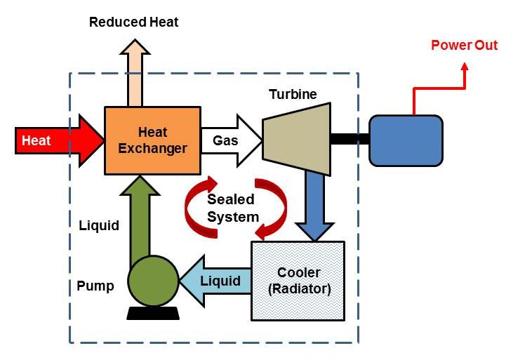
The gas turbine in a CHP plant is the core component where the high-temperature, high-pressure gases produced in the combustion chamber are converted into mechanical energy, which drives the electric generator and produces the shaft power necessary for cogeneration. As the hot gases expand through the turbine stages, they transfer their energy to the turbine blades, causing the rotor to spin at very high speeds. These blades are carefully designed to handle extreme thermal and mechanical stresses while ensuring aerodynamic efficiency. The turbine’s rotation is directly linked to the compressor at the front of the machine, which requires a significant portion of the mechanical energy to compress incoming air, and to the generator, which produces electricity. This dual coupling makes the gas turbine the central hub of energy transformation in a CHP system.
The turbine consists of multiple stages of alternating rotating and stationary blades. Stationary vanes direct the flow of gases onto the rotating blades at the optimal angle, maximizing energy extraction. Each stage converts a portion of the gas’s thermal and kinetic energy into rotational motion, and by the time the gases leave the turbine, their pressure and temperature have decreased significantly, yet they still contain enough thermal energy to be recovered for heat applications. Materials used in turbine construction are critical, as the blades and rotor are subjected to temperatures exceeding 1,200 °C and high centrifugal forces. High-performance alloys, often nickel-based, and thermal barrier coatings protect the blades from heat and oxidation, while internal cooling passages allow controlled airflow from the compressor to reduce blade temperatures. These design features ensure long operational life and reliable performance under continuous CHP operation.
The mechanical power generated by the turbine is distributed between driving the compressor, which sustains the air compression cycle, and powering the electric generator to produce electricity. In modern gas turbines, the balance between these outputs is carefully optimized to ensure maximum overall efficiency. Part-load operation, which is common in CHP plants responding to variable electricity and heat demand, requires sophisticated control systems to maintain combustion stability, manage turbine blade cooling, and ensure smooth operation. These systems monitor turbine speed, exhaust temperature, and vibration levels in real time, allowing rapid adjustments to fuel flow and operational parameters, maintaining both reliability and performance.
The exhaust gases leaving the turbine, while cooler than the combustion gases, remain extremely hot, typically in the range of 400–600 °C. This high-temperature exhaust is the cornerstone of cogeneration, as it feeds the heat recovery steam generator or other thermal recovery systems. The efficiency of the turbine directly influences the temperature and flow rate of these gases, determining how much recoverable heat is available for industrial processes, district heating, or additional electricity generation through a steam turbine in a combined cycle configuration. A turbine that operates efficiently ensures that the exhaust carries maximum usable energy, enabling the plant to achieve total efficiencies of 70–80 percent or higher, far surpassing conventional electricity-only generation.
Operational flexibility is another advantage of gas turbines in CHP plants. They can start up quickly compared to steam turbines, allowing the plant to respond to sudden changes in electricity or heat demand. Control systems manage turbine acceleration, fuel injection, and blade cooling to prevent thermal stress during ramp-up and ramp-down operations. This flexibility is particularly valuable in industrial facilities with fluctuating process loads or in urban district heating networks with daily and seasonal variations in thermal demand. The turbine’s ability to maintain efficiency across these variable conditions is critical to sustaining overall cogeneration performance.
Reliability and maintenance of the turbine are central to uninterrupted CHP operation. Vibration monitoring, temperature sensing, and blade inspections help prevent failures that could disrupt both electricity and heat supply. Scheduled maintenance, combined with predictive diagnostics, ensures that components such as blades, bearings, and seals are replaced or repaired before they cause downtime. Given that many CHP plants operate continuously to meet both electrical and thermal loads, maintaining turbine reliability is essential for plant economics and operational safety.
The gas turbine also provides a platform for integrating low-carbon and renewable fuels. Many modern turbines are capable of operating on hydrogen, biogas, or syngas blends, allowing operators to reduce carbon emissions while maintaining high efficiency and reliable performance. This adaptability ensures that CHP plants can contribute to sustainable energy strategies without compromising their operational objectives.
Economically, the gas turbine is the primary driver of cogeneration value. Its ability to convert fuel energy into mechanical and electrical output, while providing high-quality exhaust for thermal recovery, allows operators to achieve maximum energy yield from each unit of fuel. This dual output reduces fuel costs, improves return on investment, and supports energy security in industrial and urban applications. The turbine’s integration with the generator and heat recovery systems ensures that both electricity and heat are produced efficiently, reliably, and cost-effectively, fulfilling the fundamental goal of combined heat and power generation.
In summary, the gas turbine in a CHP plant is the mechanical heart of the system, converting the energy of combustion gases into rotation that drives electricity generation while producing high-temperature exhaust for heat recovery. Its advanced materials, aerodynamic blade design, cooling systems, and integrated control technologies allow continuous, efficient, and reliable operation. By linking the turbine to both electricity and heat outputs, a gas turbine enables the full potential of cogeneration, maximizing fuel utilization and supporting sustainable energy production for industrial, commercial, and urban applications.
Continuing with the gas turbine in a CHP plant, it is important to emphasize that its operation is not solely about converting thermal energy into mechanical motion but also about maintaining a delicate balance between efficiency, reliability, and integration with the overall cogeneration system. The turbine must handle extremely high temperatures and pressures while continuously supplying mechanical energy to the generator and compressor, all without compromising the quality of exhaust heat that will be recovered for district heating, industrial processes, or steam production. Its performance directly affects not only electricity generation but also the efficiency of the entire CHP plant, making it one of the most critical and closely monitored components in the system.
The aerodynamic design of turbine blades is essential to maximize energy extraction from the expanding combustion gases. Blades are shaped to optimize the conversion of kinetic and thermal energy into rotational motion while minimizing losses due to turbulence or flow separation. Advanced gas turbines use multiple stages of blades and stator vanes, each carefully calculated to extract energy incrementally as gases move through the turbine. High-performance materials such as nickel-based superalloys and ceramic coatings allow these blades to withstand the extreme temperatures and stresses generated during continuous operation. Internal cooling passages, fed by compressed air bled from the front-end compressor, help maintain structural integrity and prevent thermal fatigue, ensuring that the turbine can operate reliably for tens of thousands of hours.
The gas turbine’s operational flexibility is a key advantage for CHP plants, particularly in applications with variable electricity and thermal demand. The turbine can ramp up or down relatively quickly compared to other prime movers, adjusting output to match real-time energy requirements. This capability is critical in district heating networks, where seasonal and daily demand fluctuations are common, as well as in industrial processes that experience variable loads. Advanced turbine control systems manage fuel flow, combustion stability, and rotor speed to maintain optimal efficiency and protect components from thermal and mechanical stress during load changes. These systems also monitor vibration, exhaust temperature, and shaft alignment to prevent failures and maximize reliability.
Exhaust gas management is intrinsically linked to turbine performance in a CHP plant. Even after expanding through the turbine stages, the gases remain at high temperatures, typically between 400 and 600 °C, and carry substantial energy that can be recovered in a heat recovery steam generator or used directly for industrial heating. The turbine’s efficiency determines how much mechanical energy is extracted versus how much thermal energy remains in the exhaust. A well-designed turbine balances these outputs to optimize overall plant efficiency, allowing simultaneous electricity generation and high-quality heat recovery. Poor turbine performance can reduce exhaust gas temperature, limiting the potential for cogeneration and diminishing the economic and environmental benefits of the plant.
Reliability and maintenance are paramount in CHP operations. Gas turbines must function continuously, often under 24/7 load conditions, supplying both electricity and thermal energy. Any unexpected downtime can disrupt industrial processes or district heating systems. Predictive maintenance strategies, based on real-time monitoring of temperature, pressure, vibration, and rotational speed, allow operators to identify wear or potential failure before it leads to unplanned shutdowns. Routine inspections, cleaning of turbine blades, and replacement of critical components are scheduled to maintain performance over the turbine’s operational life. Such maintenance practices ensure that the CHP plant operates efficiently, safely, and economically.
Environmental considerations are closely tied to turbine operation. Efficient combustion and energy conversion reduce fuel consumption and lower carbon dioxide emissions per unit of energy delivered. Modern turbines can also operate on low-carbon fuels such as hydrogen, biogas, or synthetic gases, enabling cogeneration plants to participate in decarbonization efforts without compromising output or reliability. The turbine’s ability to maintain high efficiency across varying loads further ensures that emissions remain within regulatory limits even during part-load operation, making gas turbines suitable for urban and industrial environments where environmental performance is a priority.
Economically, the gas turbine is the backbone of CHP profitability. Its capacity to produce both electricity and usable thermal energy allows operators to extract maximum value from each unit of fuel. By combining mechanical efficiency with high-quality exhaust heat, CHP plants can achieve total efficiencies of 70–80 percent or more, significantly higher than conventional electricity-only plants. This efficiency translates directly into reduced fuel costs, lower emissions, and improved financial returns, making the turbine not just a mechanical component but a strategic asset in energy management and sustainability planning.
In essence, the gas turbine in a CHP plant is a sophisticated energy converter that integrates advanced materials, aerodynamic design, cooling systems, and real-time control technologies to deliver mechanical power for electricity generation while producing high-temperature exhaust suitable for heat recovery. Its performance defines the efficiency, reliability, and economic viability of the cogeneration plant, ensuring that fuel is used effectively and that both electricity and heat are delivered consistently to meet industrial, commercial, or urban energy demands. By maintaining a precise balance between mechanical output and thermal energy retention, the gas turbine enables the full potential of combined heat and power generation, supporting sustainable and cost-effective energy production.
Electric Generator
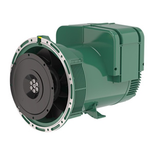
The electric generator in a gas turbine CHP plant is the component responsible for converting the mechanical energy delivered by the rotating turbine shaft into electrical energy suitable for use on-site or for export to the grid. As the turbine spins, the generator rotor rotates within a stationary stator equipped with windings and a magnetic field, inducing an alternating current through electromagnetic principles. The quality, stability, and efficiency of this conversion process are crucial because they determine how much of the turbine’s mechanical energy is successfully converted into usable electricity. Any inefficiency in the generator reduces the net electrical output, impacting both the economic performance of the plant and the effectiveness of the cogeneration system as a whole.
Modern generators in CHP plants are typically synchronous machines, capable of producing electricity at a stable frequency and voltage, even under varying load conditions. This stability is essential for industrial operations that require a reliable and continuous electricity supply, as well as for district heating or commercial networks where fluctuations in voltage or frequency could damage equipment. The generator is carefully matched to the turbine to ensure optimal rotational speed, torque, and power output, allowing the turbine to operate efficiently while providing sufficient electrical power for internal loads or external consumption. Advanced control systems monitor excitation, voltage, current, and temperature to maintain precise output, prevent overloading, and protect against electrical faults.
Cooling and thermal management are key aspects of generator operation in CHP plants. Continuous electricity generation produces heat in the windings and core, which must be effectively dissipated to prevent insulation breakdown, loss of efficiency, or premature failure. Smaller generators often use air cooling, while larger units, particularly in industrial or large district heating applications, employ hydrogen cooling or liquid cooling to maximize heat removal and maintain stable operation. These cooling systems, combined with robust insulation and high-quality materials, allow the generator to operate continuously at high load with minimal maintenance requirements.
The generator’s performance directly affects the turbine and the cogeneration process. By drawing the appropriate mechanical load from the turbine, the generator ensures that the turbine operates within its optimal efficiency range. If the generator is poorly matched, underloaded, or experiences losses, the turbine may run inefficiently, reducing both electrical output and the temperature of exhaust gases available for heat recovery. Conversely, a well-designed and properly maintained generator allows the turbine to extract maximum mechanical energy from the combustion gases, ensuring that both electricity and thermal energy are efficiently produced for cogeneration purposes.
Reliability and maintenance of the generator are critical to continuous CHP operation. Sensors monitor vibration, temperature, and electrical parameters to detect early signs of wear or failure. Scheduled maintenance, including inspection of windings, bearings, and insulation, ensures that the generator continues to operate at peak efficiency. Predictive maintenance based on real-time data allows operators to plan interventions before problems arise, reducing downtime and maintaining uninterrupted electricity and heat supply, which is particularly important in industrial processes or district heating networks that rely on continuous operation.
Economically, the generator is a key driver of CHP plant profitability. By efficiently converting mechanical energy into electricity, it ensures that the plant maximizes the value derived from the fuel consumed. High generator efficiency reduces energy losses, lowers operating costs, and enhances the financial return of the CHP system. In combination with the heat recovery system, the generator enables the plant to achieve total energy efficiencies of 70–80 percent or more, making cogeneration far more economical and environmentally sustainable than separate production of electricity and heat.
Environmentally, an efficient generator contributes indirectly to lower emissions by maximizing the usable energy extracted from fuel. Higher conversion efficiency reduces fuel consumption per unit of energy delivered, lowering carbon dioxide and pollutant emissions. When paired with a gas turbine capable of operating on renewable or low-carbon fuels, the generator becomes an essential component in producing cleaner energy while maintaining high reliability and operational flexibility.
In summary, the electric generator in a gas turbine CHP plant serves as the mechanical-to-electrical energy conversion hub. Its design, cooling, and control systems ensure stable, efficient, and reliable electricity production while enabling the turbine to operate optimally and deliver high-quality exhaust gases for heat recovery. By integrating seamlessly with the turbine and combustion systems, the generator ensures that both electricity and thermal energy are produced efficiently, supporting the dual objectives of cogeneration and enabling industrial, commercial, and urban energy applications to operate sustainably and economically.
The electric generator in a gas turbine CHP plant is the device that converts the mechanical energy produced by the turbine into electrical energy that can be used on-site or supplied to the grid. As the turbine rotor spins under the force of expanding high-temperature gases from the combustor, the generator rotor rotates within a magnetic field, inducing an alternating current in the stator windings. This conversion process is critical because the amount of electricity available for use depends directly on the generator’s efficiency and its ability to handle the turbine’s rotational speed and torque. Any inefficiency in the generator reduces the overall energy output of the CHP plant and can affect both operational costs and the effectiveness of cogeneration.
Most gas turbine generators in CHP plants are synchronous machines, which maintain a stable voltage and frequency even when electrical loads vary. This stability is essential for industrial applications, commercial facilities, and district heating systems that rely on consistent electrical power. The generator is precisely matched to the turbine’s characteristics to ensure that the turbine can operate at optimal efficiency while producing the required electrical output. Advanced control systems continuously monitor voltage, current, excitation, temperature, and other parameters to maintain stability, protect against overloads, and optimize efficiency.
Cooling is a vital aspect of generator operation, especially in CHP plants that run continuously. As electricity is generated, heat is produced in the rotor and stator windings, and this heat must be removed to prevent insulation degradation or efficiency loss. Smaller generators may use air cooling, while larger units often employ hydrogen or liquid cooling systems to improve heat dissipation and maintain stable operation. Proper thermal management ensures long operational life and reliable electricity production, which is crucial for CHP plants that supply both electricity and thermal energy around the clock.
The generator also influences the turbine’s performance. By drawing mechanical load appropriately, it ensures the turbine operates within its optimal efficiency range. If the generator is mismatched or suffers from losses, turbine efficiency decreases, reducing both electricity output and the temperature of the exhaust gases needed for heat recovery. Conversely, a well-designed and properly maintained generator allows the turbine to operate efficiently, producing high-quality exhaust gases that can be effectively used in the heat recovery steam generator or other thermal systems.
Maintenance and monitoring are critical to generator reliability. Sensors track vibration, temperature, and electrical parameters to detect early signs of wear or failure. Routine inspections of windings, bearings, and insulation help prevent unexpected downtime. Predictive maintenance using real-time data ensures continuous operation, which is especially important in CHP plants where both electricity and heat must be supplied consistently for industrial or district heating purposes.
Economically, the generator is central to CHP plant profitability. Efficient conversion of mechanical to electrical energy reduces fuel costs and operational losses, maximizing the value of the fuel consumed. In combination with the turbine and heat recovery systems, the generator contributes to the high overall efficiency of cogeneration plants, often reaching total energy efficiencies of 70–80 percent or more. This dual output of electricity and heat makes CHP plants more economical and environmentally friendly compared to separate electricity and heat production.
Environmentally, a high-efficiency generator indirectly reduces emissions. By maximizing the electricity output for a given fuel input, the plant consumes less fuel per unit of energy delivered, lowering CO₂ and other pollutant emissions. When paired with a turbine capable of using renewable or low-carbon fuels, the generator helps the CHP plant operate sustainably while maintaining reliable and flexible energy production.
In summary, the electric generator is the key component that converts the mechanical energy of the gas turbine into usable electricity while supporting the overall cogeneration process. Its design, cooling, control, and integration with the turbine ensure reliable, efficient, and stable electricity production while enabling high-quality exhaust gases for heat recovery. In this way, the generator is essential to achieving the dual goals of CHP: providing both electricity and thermal energy efficiently, economically, and sustainably.
The electric generator in a gas turbine CHP plant serves as the critical link between mechanical energy produced by the turbine and the usable electrical power required for industrial, commercial, or grid applications. As the turbine rotor spins under the high-pressure, high-temperature gases from the combustor, the generator rotor rotates within a strong magnetic field, inducing alternating current in the stator windings. This conversion must be highly efficient, because any energy lost during this process reduces the overall electrical output of the CHP system and limits the total energy that can be recovered from the fuel. In cogeneration systems, the generator’s performance also indirectly affects thermal recovery, since the load applied to the turbine influences the temperature and flow of the exhaust gases used in heat recovery.
Most generators in gas turbine CHP plants are synchronous machines, designed to maintain stable voltage and frequency under varying loads. This stability is essential for continuous industrial operations, district heating networks, or other applications that require reliable electricity. The generator is carefully matched to the turbine’s mechanical characteristics to ensure optimal rotational speed, torque, and power output. Advanced control systems continuously monitor parameters such as excitation, voltage, current, temperature, and vibration to maintain stable operation, protect against electrical faults, and optimize efficiency. These systems also enable smooth load adjustments, allowing the CHP plant to respond flexibly to variations in electricity demand while maintaining stable operation.
Thermal management is a key aspect of generator reliability and efficiency. Continuous electricity generation produces significant heat in the rotor and stator windings, which must be removed to prevent insulation breakdown, efficiency loss, or damage. Smaller units often use air cooling, while larger industrial generators may use hydrogen or liquid cooling systems, which provide superior heat removal and allow the generator to operate continuously at high load. Proper cooling ensures long-term reliability and reduces maintenance requirements, supporting uninterrupted operation in CHP plants where both electricity and heat are required around the clock.
The generator’s load characteristics also influence turbine performance and overall cogeneration efficiency. By drawing the correct mechanical load from the turbine, the generator ensures that the turbine operates within its optimal efficiency range, which maximizes both electricity production and the thermal energy remaining in the exhaust gases. If the generator is mismatched or inefficient, turbine output may be reduced, and exhaust gas temperatures may drop, limiting heat recovery for industrial or district heating applications. A well-designed generator allows the turbine to deliver maximum mechanical energy while producing exhaust gases that are ideal for heat recovery, ensuring high overall CHP efficiency.
Reliability and maintenance are crucial for continuous operation. Generators are equipped with sensors to monitor vibration, temperature, and electrical parameters in real time, enabling predictive maintenance to prevent unplanned downtime. Routine inspections of windings, bearings, insulation, and other components ensure safe and efficient operation over thousands of hours. In CHP plants, where both electricity and heat are critical, maintaining generator reliability is essential to avoid disruptions in power supply or thermal energy distribution.
From an economic standpoint, the generator directly affects plant profitability. Efficient electricity generation maximizes the energy extracted from fuel, reducing operating costs and enhancing financial returns. When combined with the turbine and heat recovery systems, the generator enables CHP plants to achieve total energy efficiencies of 70–80 percent or higher, far exceeding conventional electricity-only generation. This dual output reduces fuel consumption, lowers costs, and provides both electricity and thermal energy for industrial, commercial, or district heating applications.
Environmentally, the generator contributes indirectly to emissions reduction. By efficiently converting mechanical energy into electricity, the plant uses less fuel per unit of energy delivered, reducing CO₂ and pollutant emissions. When operating on renewable or low-carbon fuels, the generator ensures that the CHP system maintains high efficiency and reliability while supporting sustainability and regulatory compliance.
In summary, the electric generator is the essential component that transforms the turbine’s mechanical power into usable electricity, enabling the CHP plant to supply reliable, high-quality electrical energy while supporting the recovery of thermal energy for cogeneration. Its design, cooling, control systems, and integration with the turbine ensure efficiency, stability, and continuous operation, making it central to the overall performance, economics, and sustainability of gas turbine CHP plants.
The electric generator in a gas turbine CHP plant is the component that converts the mechanical energy produced by the turbine into electrical energy that can be used on-site or exported to the grid. As the turbine rotor spins under the force of high-pressure, high-temperature gases from the combustion chamber, the generator rotor rotates within a magnetic field, inducing alternating current in the stator windings. The efficiency of this conversion process is critical because it determines how much of the turbine’s mechanical energy is transformed into usable electricity, directly affecting both the plant’s electrical output and overall cogeneration efficiency. Any inefficiency in the generator not only reduces electricity production but can also impact the temperature and flow of exhaust gases available for heat recovery, thereby influencing the plant’s total energy yield.
Most gas turbine CHP generators are synchronous machines capable of maintaining stable voltage and frequency even when loads fluctuate. This stability is essential for industrial processes, commercial facilities, and district heating systems that require reliable electricity. The generator is carefully matched to the turbine to ensure optimal rotational speed and torque, allowing the turbine to operate efficiently while producing the required electrical output. Advanced control systems monitor voltage, current, excitation, temperature, and vibration, adjusting operating parameters in real time to maintain stability, optimize efficiency, and protect against electrical faults.
Cooling is a vital consideration, particularly in CHP plants that operate continuously. As electrical power is generated, heat is produced in the rotor and stator windings, which must be removed to prevent insulation breakdown and maintain efficiency. Smaller units often employ air cooling, while larger industrial generators may use hydrogen or liquid cooling systems, which provide superior heat removal and allow operation at high load over extended periods. Effective cooling ensures long-term reliability, minimizes maintenance, and supports uninterrupted operation, which is critical in CHP plants that provide both electricity and thermal energy continuously.
The generator’s mechanical load also influences turbine performance and overall plant efficiency. By drawing the appropriate load from the turbine, the generator ensures that the turbine operates within its optimal efficiency range, maximizing electricity output and maintaining the thermal energy in the exhaust for cogeneration. A poorly matched or inefficient generator can reduce turbine efficiency, lowering electrical output and exhaust temperatures, which limits the heat available for industrial processes or district heating. Conversely, a well-designed and maintained generator allows the turbine to operate efficiently, producing both high-quality electricity and exhaust suitable for heat recovery.
Reliability and maintenance are central to generator performance. Sensors monitor temperature, vibration, and electrical parameters to detect early signs of wear or failure. Routine inspections of windings, bearings, and insulation, combined with predictive maintenance strategies, ensure continuous, efficient operation. In CHP plants, where uninterrupted supply of both electricity and thermal energy is critical, maintaining generator reliability is essential for plant performance, safety, and economic operation.
Economically, the generator plays a major role in CHP plant profitability. High-efficiency electricity generation maximizes the energy extracted from fuel, reducing operating costs and improving financial returns. When combined with the turbine and heat recovery systems, the generator helps the plant achieve total energy efficiencies of 70–80 percent or more, far exceeding conventional electricity-only plants. This dual output of electricity and heat reduces fuel consumption, lowers emissions, and ensures that the CHP system is both economical and environmentally sustainable.
Environmentally, a high-performance generator indirectly reduces emissions by maximizing energy conversion. By extracting more electricity from the same fuel input, the plant reduces carbon dioxide and other pollutant emissions per unit of energy delivered. When paired with turbines capable of using renewable or low-carbon fuels such as biogas or hydrogen, the generator supports sustainable operation without compromising output or reliability.
In summary, the electric generator in a gas turbine CHP plant is essential for transforming mechanical energy into usable electricity while maintaining the overall efficiency and reliability of the cogeneration system. Its design, control systems, cooling methods, and integration with the turbine ensure stable, continuous, and high-quality electricity production while enabling the recovery of exhaust heat for cogeneration. The generator thus serves as a central component in achieving the dual objectives of combined heat and power: providing both electricity and thermal energy efficiently, reliably, and sustainably.
Exhaust Gas System
The exhaust gas system in a gas turbine CHP plant is the critical pathway through which the hot gases exiting the turbine are directed toward energy recovery, emissions control, and safe release into the environment. After passing through the turbine, these gases still retain a significant amount of thermal energy, often in the range of 400–600 °C, which can be harnessed for cogeneration purposes. The design and operation of the exhaust system are therefore central to maximizing the overall efficiency of the CHP plant, as it determines how effectively the residual heat can be recovered in the heat recovery steam generator (HRSG) or used directly for industrial processes or district heating.
The exhaust system typically begins with a duct or transition piece that captures the turbine exhaust and channels it efficiently toward the HRSG. These ducts are carefully engineered to minimize pressure drop and turbulence, which could reduce energy recovery efficiency. High-temperature alloys and thermal insulation are used to withstand the extreme temperatures and prevent heat loss before the gases reach the recovery system. Additionally, vibration dampers and expansion joints are incorporated to accommodate thermal expansion and mechanical stresses, ensuring safe and reliable long-term operation.
Before the gases enter the HRSG, the system often includes monitoring and control equipment to measure temperature, flow rate, and composition. These measurements are essential for optimizing heat recovery, controlling emissions, and maintaining turbine performance. Some systems may also include particulate or gas filters to remove contaminants or protect downstream equipment, particularly in plants burning alternative fuels such as biogas or syngas, which may contain impurities. By controlling the characteristics of the exhaust gas stream, the system ensures that the HRSG operates at optimal efficiency and that the recovered heat meets process or district heating requirements.
The exhaust system also plays a role in emissions management. Modern CHP plants are subject to strict regulations for nitrogen oxides (NOx), carbon monoxide (CO), unburned hydrocarbons, and other pollutants. The exhaust system may include devices such as selective catalytic reduction (SCR) units, catalytic oxidizers, or flue gas recirculation systems to reduce emissions before the gases are released or recovered for heat. The proper integration of these systems is crucial for meeting environmental standards while maintaining high thermal recovery efficiency.
Operational flexibility is an important feature of the exhaust system. CHP plants must often respond to variations in electricity and heat demand, which affect turbine load and exhaust gas temperature. Dampers, bypass systems, and control valves allow operators to direct a portion of the exhaust gas around the HRSG during periods of low heat demand or to mix gases for optimal temperature control. These features ensure that the plant can maintain safe operation, prevent overheating or underheating of heat recovery equipment, and adjust output according to process requirements or district heating needs.
Maintenance and durability are key considerations in the exhaust system. High temperatures and continuous operation place significant thermal and mechanical stress on ducts, insulation, and support structures. Regular inspections for corrosion, erosion, and thermal fatigue, combined with predictive monitoring, help ensure the system remains safe and efficient over the plant’s lifetime. Thermal expansion, vibration, and exposure to combustion byproducts are accounted for in design and operation to prevent failures that could disrupt both electricity and heat supply.
Economically, the exhaust system’s design directly impacts the efficiency and profitability of the CHP plant. By minimizing heat loss and directing high-temperature gases effectively to the HRSG, the system maximizes the amount of recoverable thermal energy, reducing fuel consumption and operational costs. Efficient exhaust management also reduces wear and tear on downstream equipment, lowering maintenance costs and extending service life. In plants integrated with industrial processes or district heating networks, reliable exhaust gas flow ensures consistent supply of hot water, steam, or process heat, supporting both operational continuity and revenue generation.
In summary, the exhaust gas system in a gas turbine CHP plant is a vital component that transports the turbine’s hot gases safely and efficiently to the heat recovery system or into the environment. It integrates high-temperature materials, aerodynamic design, thermal insulation, monitoring systems, and emissions controls to ensure maximum energy recovery, environmental compliance, and operational reliability. By capturing and directing the residual heat of turbine exhaust, the system enables the CHP plant to fulfill its dual objectives of producing electricity and useful thermal energy efficiently, sustainably, and economically.
The exhaust gas system in a gas turbine CHP plant is the pathway through which the high-temperature gases leaving the turbine are directed for heat recovery, emissions control, and eventual release to the atmosphere. After expansion in the turbine, these gases still carry substantial thermal energy, often between 400 and 600 °C, which can be harnessed in the heat recovery steam generator (HRSG) or used directly for industrial heating or district energy applications. The efficiency of this system is critical, as it determines how much of the remaining energy in the exhaust can be recovered for cogeneration, directly affecting the overall energy efficiency of the CHP plant.
Exhaust ducts and transition pieces connect the turbine outlet to the HRSG, ensuring that the gases flow smoothly with minimal turbulence and pressure loss. These ducts are designed from high-temperature alloys and often insulated to prevent energy losses before the gases reach the recovery system. Expansion joints, vibration dampers, and flexible supports are incorporated to handle thermal expansion, mechanical stresses, and vibration caused by the high-speed gas flow, ensuring safe and reliable operation over the life of the plant.
Monitoring and control systems are integral to the exhaust gas system. Sensors measure temperature, flow rate, and gas composition to optimize heat recovery and control emissions. This data allows operators to adjust turbine operation, exhaust flow, or bypass systems to ensure the HRSG operates efficiently and that the heat delivered meets process or district heating requirements. In some applications, the exhaust may be treated to remove particulates or contaminants, especially when the plant operates on alternative fuels like biogas or syngas.
Environmental compliance is a key function of the exhaust system. Modern gas turbine CHP plants often include selective catalytic reduction (SCR) units, catalytic oxidizers, or flue gas recirculation systems to reduce nitrogen oxides (NOx), carbon monoxide (CO), and unburned hydrocarbons before release. Proper integration of these technologies ensures emissions remain within regulatory limits while maintaining high thermal recovery efficiency.
Operational flexibility is built into the exhaust system to respond to variable electricity and heat demands. Dampers, bypass lines, and control valves allow a portion of the exhaust gas to bypass the HRSG during periods of low heat demand, preventing overheating or underutilization of the heat recovery equipment. These controls ensure the plant can maintain safe operation while delivering consistent electricity and thermal energy output.
Maintenance and durability are crucial because the exhaust system operates under extreme temperatures and continuous flow. Regular inspections detect erosion, corrosion, or thermal fatigue, while predictive monitoring allows timely maintenance before failures occur. Proper design and maintenance ensure uninterrupted delivery of both electricity and heat, protecting the plant’s operational reliability and economic performance.
Economically, the exhaust gas system enhances the CHP plant’s efficiency and cost-effectiveness. By minimizing heat losses and directing hot gases efficiently to the HRSG or heat users, the system maximizes recoverable thermal energy, reduces fuel consumption, and lowers operational costs. Efficient exhaust management also reduces wear on downstream equipment, prolonging service life and minimizing maintenance expenditures.
In summary, the exhaust gas system in a gas turbine CHP plant safely and efficiently channels high-temperature turbine gases to recovery systems or the atmosphere, integrating thermal insulation, structural support, monitoring, and emissions control. It is essential for maximizing energy recovery, maintaining environmental compliance, and ensuring the reliability and economic efficiency of the CHP plant by enabling effective cogeneration of electricity and heat.
The exhaust gas system in a gas turbine CHP plant is the critical conduit for directing the high-temperature gases exiting the turbine toward energy recovery, emissions control, and safe discharge. After passing through the turbine, the gases retain substantial thermal energy, often between 400 and 600 °C, which can be harnessed for cogeneration through a heat recovery steam generator (HRSG) or directly for industrial processes or district heating. The system’s efficiency is vital, as it determines how much of this residual energy can be captured, affecting both the plant’s overall energy efficiency and economic performance.
Exhaust ducts and transition pieces are designed to guide the turbine’s hot gases with minimal pressure loss and turbulence, ensuring efficient energy transfer to the HRSG. High-temperature alloys and thermal insulation are used to withstand extreme conditions and reduce heat losses. Expansion joints, vibration dampers, and flexible supports accommodate thermal expansion and mechanical stresses caused by high-speed gas flow, maintaining safe, reliable operation over long periods.
Monitoring and control of the exhaust gases are essential. Sensors measure temperature, flow rate, and gas composition to optimize heat recovery, adjust turbine operation, and maintain compliance with emissions standards. In plants burning alternative fuels such as biogas or syngas, filters or gas-cleaning devices may be integrated to remove particulates or contaminants, protecting downstream heat recovery equipment and ensuring stable operation.
The exhaust system also plays a key role in environmental compliance. Modern CHP plants often include selective catalytic reduction (SCR) units, catalytic oxidizers, or flue gas recirculation systems to reduce nitrogen oxides (NOx), carbon monoxide (CO), and unburned hydrocarbons before the gases are released or recovered for heat. Proper integration of these technologies ensures regulatory compliance while maintaining high energy recovery efficiency.
Operational flexibility is another important aspect. Dampers, bypass lines, and control valves allow a portion of the exhaust to bypass the HRSG during periods of low heat demand, preventing overheating or underutilization of the heat recovery system. This flexibility ensures that the plant can respond to fluctuating electricity and thermal loads without compromising turbine performance or safety.
Maintenance and durability are crucial because the exhaust system operates continuously under high temperatures and pressures. Regular inspections detect corrosion, erosion, or thermal fatigue, while predictive monitoring enables proactive maintenance to prevent unplanned shutdowns. Proper design and upkeep ensure reliable operation, safeguarding both electricity and heat supply.
Economically, the exhaust gas system enhances plant efficiency and reduces operating costs by maximizing heat recovery. By minimizing heat losses and directing gases efficiently to the HRSG or other heat users, the system ensures optimal fuel utilization. Efficient exhaust management also prolongs the service life of downstream equipment, reducing maintenance expenditures and supporting the plant’s financial performance.
In summary, the exhaust gas system in a gas turbine CHP plant safely and efficiently channels turbine exhaust to heat recovery systems or the atmosphere. It integrates thermal insulation, structural support, monitoring, and emissions controls to maximize energy recovery, maintain environmental compliance, and ensure operational reliability. This system is central to enabling cogeneration, allowing the plant to deliver both electricity and usable thermal energy efficiently, sustainably, and economically
Heat Recovery Steam Generator (HRSG)
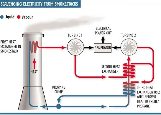
The Heat Recovery Steam Generator (HRSG) in a gas turbine CHP plant is the key component that captures the thermal energy of the hot exhaust gases leaving the turbine and converts it into useful steam or hot water for industrial processes, district heating, or additional electricity generation in a combined cycle setup. The HRSG allows the CHP plant to achieve much higher overall efficiency compared to electricity-only generation, often raising total energy efficiency to 70–80 percent or more by making use of energy that would otherwise be wasted. Its operation is central to the concept of cogeneration, as it bridges the gap between mechanical energy production in the turbine and thermal energy utilization in the plant’s end-use systems.
The HRSG consists of a series of heat exchange sections, including economizers, evaporators, and superheaters, through which the exhaust gases pass. In the economizer section, water entering the HRSG absorbs heat from the exhaust gas, preheating it before it reaches the evaporator. In the evaporator, water is converted into saturated steam, and in the superheater, this steam is heated to the desired temperature and pressure for industrial processes, district heating, or to drive a steam turbine for additional electricity generation. The arrangement of these sections and the flow path of the exhaust gases are carefully designed to maximize heat transfer while minimizing pressure drop, ensuring efficient operation of both the HRSG and the upstream turbine.
The design of the HRSG must account for variations in exhaust gas temperature and flow caused by fluctuating turbine load and variable electricity or heat demand. Modern HRSGs are often modular, with multiple parallel gas paths and sections, allowing the plant to adjust steam production according to instantaneous requirements. Bypass systems and control valves enable the redirection of exhaust gases or partial load operation without compromising the turbine or damaging HRSG components. This flexibility is crucial for CHP plants, which often operate under varying load profiles to match industrial processes or district heating demands.
Materials and construction are critical in HRSG design due to the high temperatures and corrosive nature of exhaust gases. High-temperature steels and corrosion-resistant alloys are used in tubes and headers, while thermal insulation and protective coatings prevent heat loss and extend the service life of the components. In some plants, supplementary firing systems are integrated within the HRSG, allowing additional fuel to be burned to increase steam output during periods of high heat demand, further enhancing operational flexibility.
Monitoring and control systems are essential for safe and efficient HRSG operation. Sensors track exhaust gas temperature, steam pressure, water level, and flow rates to ensure that heat transfer is optimized and that operating limits are not exceeded. These systems also protect against tube overheating, water hammer, and other hazards, maintaining continuous and reliable steam production. Integration with turbine control systems allows coordinated operation, ensuring that the HRSG responds dynamically to changes in turbine output while maintaining consistent steam supply.
Maintenance and durability are key for long-term HRSG performance. Continuous exposure to high-temperature, high-velocity exhaust gases can lead to thermal fatigue, corrosion, or fouling. Regular inspections, cleaning, and replacement of tubes and components, combined with predictive monitoring, help maintain efficiency, prevent unplanned downtime, and extend the life of the HRSG. Proper maintenance ensures that the CHP plant can deliver both electricity and thermal energy reliably over years of continuous operation.
Economically, the HRSG significantly improves the financial viability of a CHP plant. By capturing and utilizing the turbine’s exhaust heat, fuel consumption per unit of combined energy output is reduced, lowering operating costs. Efficient steam or hot water production supports industrial processes or district heating networks, generating additional revenue streams or cost savings. When combined with high-efficiency turbines and generators, the HRSG enables the plant to achieve optimal energy utilization, making cogeneration more profitable than separate production of electricity and heat.
Environmentally, the HRSG contributes to reduced emissions by maximizing energy recovery from the fuel burned in the turbine. By using exhaust heat to produce steam or hot water, less fuel is required for supplemental heating or process energy, reducing carbon dioxide and other pollutant emissions. When integrated with turbines capable of operating on low-carbon fuels such as biogas or hydrogen, the HRSG enhances the sustainability of CHP operations, supporting both energy efficiency and environmental compliance.
In summary, the Heat Recovery Steam Generator in a gas turbine CHP plant transforms the high-temperature exhaust gases from the turbine into useful steam or hot water, enabling efficient cogeneration of electricity and heat. Its design, materials, control systems, and integration with the turbine and generator are crucial for maximizing energy recovery, maintaining operational flexibility, ensuring safety, and supporting the economic and environmental performance of the plant. The HRSG is therefore central to achieving the high overall efficiency and sustainability that define modern combined heat and power systems.
The Heat Recovery Steam Generator (HRSG) in a gas turbine CHP plant is the key component that captures the high-temperature exhaust gases leaving the gas turbine and converts their thermal energy into usable steam or hot water for industrial processes, district heating, or additional electricity generation. By recovering heat that would otherwise be wasted, the HRSG significantly increases the overall efficiency of the CHP plant, often raising total energy utilization to 70–80 percent or more. Its operation is central to cogeneration because it links the mechanical energy produced by the turbine with thermal energy output, allowing simultaneous electricity and heat production from a single fuel source.
The HRSG is composed of several heat exchange sections, including economizers, evaporators, and superheaters. In the economizer section, feedwater absorbs heat from the exhaust gases, preheating it before it enters the evaporator. In the evaporator, water is converted into saturated steam, and in the superheater, the steam is further heated to the desired temperature and pressure for industrial use, district heating, or to drive a steam turbine in a combined cycle configuration. The arrangement of these sections and the flow path of the exhaust gases are designed to maximize heat transfer while minimizing pressure drop, ensuring both high efficiency and safe operation.
Modern HRSGs are designed to handle variations in exhaust gas flow and temperature resulting from fluctuating turbine load and variable electricity or heat demand. Many units feature modular designs with multiple parallel gas paths and sections, allowing operators to adjust steam production to meet real-time requirements. Bypass systems and control valves provide flexibility to divert exhaust gases or modulate flow during low-load conditions without compromising turbine operation or HRSG integrity. This operational flexibility is critical in CHP plants, which must adapt to changing industrial process loads or district heating demands throughout the day or across seasons.
Materials and construction are critical due to the high temperatures and corrosive nature of turbine exhaust gases. HRSG tubes and headers are made from high-temperature steels and corrosion-resistant alloys, while insulation and protective coatings reduce heat loss and extend service life. In some installations, supplementary firing systems are integrated within the HRSG to increase steam output during periods of high heat demand, further enhancing operational flexibility and enabling the CHP plant to meet variable thermal requirements.
Monitoring and control systems are essential for safe and efficient operation. Sensors track exhaust gas temperature, steam pressure, water levels, and flow rates to ensure optimized heat transfer and to prevent hazards such as overheating or water hammer. The HRSG is often closely integrated with the turbine control system, allowing coordinated adjustments to turbine output and steam generation, maintaining consistent energy delivery even under fluctuating loads.
Maintenance and durability are critical for long-term performance. Continuous exposure to high-temperature exhaust gases can lead to thermal fatigue, corrosion, or fouling of the heat exchange surfaces. Regular inspections, cleaning, and component replacement, combined with predictive monitoring, help maintain efficiency, prevent unplanned downtime, and extend the operational life of the HRSG. Reliable maintenance practices ensure that the CHP plant can continuously deliver both electricity and thermal energy.
Economically, the HRSG enhances the financial viability of a CHP plant by maximizing the use of fuel energy. By converting turbine exhaust into steam or hot water, the plant reduces fuel consumption for supplemental heating and industrial processes, lowering operational costs. Efficient energy recovery from the HRSG supports industrial operations, district heating networks, and additional electricity generation, contributing to higher revenue and overall plant profitability.
Environmentally, the HRSG reduces emissions by maximizing the energy extracted from the fuel burned in the turbine. By using exhaust heat for steam or hot water production, less additional fuel is required, which lowers carbon dioxide and pollutant emissions per unit of energy delivered. When combined with turbines capable of using renewable or low-carbon fuels such as biogas or hydrogen, the HRSG significantly enhances the sustainability of CHP operations.
In summary, the Heat Recovery Steam Generator in a gas turbine CHP plant captures the turbine’s high-temperature exhaust gases and converts them into usable steam or hot water, enabling highly efficient cogeneration. Its design, materials, control systems, and integration with the turbine and generator are essential for maximizing energy recovery, operational flexibility, safety, and economic and environmental performance. The HRSG is therefore a central component in achieving the high overall efficiency and sustainability that define modern combined heat and power systems.
The Heat Recovery Steam Generator (HRSG) in a gas turbine CHP plant is a critical component that captures the thermal energy of the hot exhaust gases leaving the gas turbine and converts it into usable steam or hot water for industrial processes, district heating, or additional electricity generation in a combined cycle arrangement. By recovering heat that would otherwise be wasted, the HRSG significantly increases the overall efficiency of the CHP plant, often pushing total energy utilization to 70–80 percent or more. It is central to cogeneration because it allows simultaneous production of electricity from the turbine and thermal energy for heating or industrial use, maximizing fuel utilization and reducing overall energy costs.
The HRSG consists of several heat exchange sections, including economizers, evaporators, and superheaters. In the economizer, feedwater absorbs heat from the exhaust gases to raise its temperature before entering the evaporator. In the evaporator section, water is converted into saturated steam, and in the superheater, the steam is further heated to the required temperature and pressure for industrial processes, district heating, or to drive a steam turbine for additional electricity generation. The flow path of the exhaust gases is carefully designed to maximize heat transfer efficiency while minimizing pressure drop, ensuring optimal energy recovery from the turbine exhaust.
Modern HRSGs are designed to handle variations in exhaust gas flow and temperature caused by fluctuating turbine loads or changing heat demands. Many HRSGs feature modular designs with multiple parallel gas paths and sections, which allow operators to adjust steam production according to real-time requirements. Bypass systems and control valves permit partial load operation or the diversion of exhaust gases around certain sections of the HRSG during periods of low heat demand, preventing thermal overstress and maintaining safe operation. This operational flexibility is crucial for CHP plants supplying industrial processes or district heating networks with variable energy requirements.
Materials and construction of the HRSG are critical due to the high temperatures and potentially corrosive nature of turbine exhaust gases. Tubes and headers are made from high-temperature steels and corrosion-resistant alloys, while insulation and protective coatings reduce heat losses and prolong the life of the equipment. In some installations, supplementary firing systems are integrated within the HRSG to increase steam output during periods of high thermal demand, further enhancing operational flexibility and allowing the CHP plant to meet peak heating or process requirements.
Monitoring and control systems ensure the safe and efficient operation of the HRSG. Sensors continuously measure exhaust gas temperature, steam pressure, water levels, and flow rates to optimize heat transfer and prevent hazards such as overheating, tube rupture, or water hammer. Integration with turbine and generator controls allows coordinated operation, ensuring that steam production responds dynamically to changes in turbine output while maintaining stable and reliable delivery of thermal energy.
Maintenance and durability are essential for long-term HRSG performance. Continuous exposure to high-temperature gases can lead to thermal fatigue, corrosion, or fouling. Regular inspections, cleaning, and replacement of tubes and components, combined with predictive monitoring, maintain efficiency, prevent unplanned downtime, and extend the life of the HRSG. Proper maintenance ensures continuous, reliable delivery of both electricity and thermal energy.
Economically, the HRSG greatly enhances CHP plant efficiency and cost-effectiveness. By converting turbine exhaust into steam or hot water, the plant reduces fuel consumption for supplemental heating or industrial processes, lowering operating costs. Efficient heat recovery enables CHP plants to provide electricity and thermal energy simultaneously, improving profitability and maximizing energy output per unit of fuel.
Environmentally, the HRSG contributes to emissions reduction by maximizing the energy extracted from the fuel burned in the gas turbine. By using exhaust heat for steam or hot water production, less additional fuel is required, reducing carbon dioxide and other pollutant emissions. When paired with turbines capable of burning low-carbon or renewable fuels such as biogas or hydrogen, the HRSG further enhances the sustainability of CHP operations.
In summary, the Heat Recovery Steam Generator in a gas turbine CHP plant converts high-temperature turbine exhaust into useful steam or hot water, enabling highly efficient cogeneration. Its design, materials, control systems, and integration with the turbine and generator are essential for maximizing energy recovery, operational flexibility, safety, and economic and environmental performance. The HRSG is therefore a central component in achieving the high overall efficiency and sustainability characteristic of modern combined heat and power systems.
Steam Turbine (in Combined Cycle CHP)
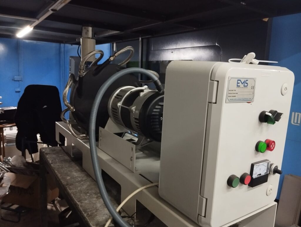
In a combined cycle CHP plant, the steam turbine is the component that converts the thermal energy recovered from the gas turbine exhaust into additional mechanical energy, which is then transformed into electricity by an electric generator. Steam turbines in CHP applications are driven by high-pressure, high-temperature steam produced in the Heat Recovery Steam Generator (HRSG). By utilizing the exhaust heat from the gas turbine, the steam turbine allows the plant to achieve significantly higher overall efficiency than a simple gas turbine cycle, often exceeding 70–80 percent total energy utilization, as both electricity and thermal energy are produced simultaneously.
The steam turbine operates by expanding high-pressure steam through a series of rotor blades arranged in stages. The kinetic and thermal energy of the steam is transferred to the rotor, causing it to spin and drive an attached generator. The design of the turbine blades and stages is critical to maximize energy extraction while minimizing losses. Modern steam turbines often feature multiple pressure levels—high-pressure (HP), intermediate-pressure (IP), and low-pressure (LP) sections—to efficiently utilize the available steam energy from the HRSG and to optimize the steam expansion process for both electricity generation and heat supply.
Steam turbines in CHP plants are designed to integrate seamlessly with district heating or industrial processes. After expanding through the turbine stages, a portion of the low-pressure steam can be extracted at intermediate points for direct use in heating networks, industrial process heat, or other applications. This extraction process allows the plant to simultaneously generate electricity and provide high-quality thermal energy, which is the essence of cogeneration. The flexibility to control the amount of steam extracted versus expanded for electricity production is a key factor in matching plant output to real-time demand.
Material selection and construction are vital due to the high temperatures and pressures encountered in steam turbines. High-strength steels and alloys are used for rotors, blades, and casings to withstand mechanical stresses, thermal cycling, and potential corrosion from steam impurities. Advanced blade design and precise manufacturing tolerances ensure optimal aerodynamic performance, reducing energy losses and enhancing turbine efficiency. Cooling systems, seals, and bearings are incorporated to maintain operational stability and prevent overheating or mechanical wear during continuous operation.
Control systems play a central role in steam turbine operation within CHP plants. Turbine speed, steam pressure, temperature, and extraction flow are continuously monitored and adjusted to maintain optimal efficiency and protect the turbine from mechanical or thermal stress. The turbine is coordinated with the gas turbine and HRSG controls to ensure that changes in gas turbine output or steam demand are met without interruption, allowing flexible operation under variable electrical or thermal load conditions.
Maintenance and reliability are crucial because steam turbines in CHP plants operate continuously for long periods. Predictive monitoring of vibration, temperature, pressure, and rotational speed allows early detection of potential issues. Scheduled inspections and maintenance of blades, seals, bearings, and other components ensure long-term performance and minimize unplanned downtime. Reliable steam turbine operation is essential to maintaining consistent electricity generation and thermal energy supply for industrial or district heating applications.
Economically, the steam turbine maximizes the value extracted from fuel by generating additional electricity from heat that would otherwise be wasted. This secondary electricity generation improves plant efficiency and reduces fuel costs per unit of energy delivered. When combined with steam extraction for heating, the turbine supports the CHP plant’s profitability by enabling simultaneous production of electricity and thermal energy, maximizing the return on fuel investment.
Environmentally, the steam turbine contributes to reduced emissions by using waste heat from the gas turbine to produce additional electricity instead of burning extra fuel. By improving overall energy efficiency, the combined cycle CHP system reduces carbon dioxide and other pollutant emissions per unit of total energy output. When coupled with low-carbon or renewable fuels in the gas turbine, the steam turbine further enhances the plant’s environmental sustainability.
In summary, the steam turbine in a combined cycle CHP plant converts thermal energy from the HRSG into additional electricity while enabling steam extraction for heating or industrial processes. Its design, materials, control systems, and integration with the gas turbine and HRSG are essential for maximizing overall plant efficiency, operational flexibility, reliability, and economic and environmental performance. By harnessing exhaust heat that would otherwise be wasted, the steam turbine ensures that the CHP plant delivers both electricity and thermal energy efficiently, sustainably, and cost-effectively.
In a combined cycle CHP plant, the steam turbine is the component that converts thermal energy from the high-temperature steam produced in the Heat Recovery Steam Generator (HRSG) into mechanical energy, which is then transformed into electricity by an electric generator. This configuration allows the plant to utilize the exhaust heat from the gas turbine efficiently, significantly increasing the overall energy efficiency of the system. Unlike a simple gas turbine cycle, the combined cycle with a steam turbine can achieve total efficiencies of 70–80 percent or more, as it simultaneously produces electricity and captures usable heat for industrial or district heating applications.
The steam turbine operates by expanding high-pressure, high-temperature steam through a series of rotor blades arranged in multiple stages. The energy of the steam is transferred to the rotor, causing it to spin and drive an attached generator. Modern steam turbines often include multiple pressure levels—high-pressure (HP), intermediate-pressure (IP), and low-pressure (LP) sections—to maximize the extraction of energy from the steam. This staged expansion improves both electrical output and thermal efficiency by ensuring that the energy available in the steam is fully utilized before it is condensed or extracted for heating purposes.
In cogeneration applications, the steam turbine is designed to provide flexible steam extraction at various pressure levels for direct use in industrial processes or district heating. This extraction capability allows the plant to meet varying thermal demands without compromising electricity generation. The operator can adjust the amount of steam extracted versus expanded for power generation to match real-time energy requirements, providing both operational flexibility and high overall efficiency.
Material selection and construction are crucial because steam turbines operate under extreme temperature and pressure conditions. High-strength steels and corrosion-resistant alloys are used for rotors, blades, and casings to withstand thermal stresses, mechanical loads, and potential corrosion from impurities in the steam. Advanced blade designs optimize aerodynamic efficiency, reduce energy losses, and ensure long-term reliability. Bearings, seals, and cooling systems maintain stability and protect the turbine from overheating or mechanical wear during continuous operation.
Control systems are integral to the operation of the steam turbine within a CHP plant. Key parameters such as turbine speed, steam pressure, temperature, and extraction flow are continuously monitored and adjusted to maintain efficiency, protect equipment, and respond to changes in both electricity and thermal load demands. The turbine is closely coordinated with the gas turbine and HRSG controls to ensure that variations in gas turbine output or heat requirements do not disrupt operation, enabling reliable and flexible cogeneration.
Maintenance and reliability are essential for steam turbine performance. Continuous operation under high pressure and temperature requires regular inspection, monitoring, and maintenance of blades, bearings, seals, and other components. Predictive monitoring systems help detect early signs of wear or imbalance, preventing unplanned shutdowns and ensuring the continuous supply of both electricity and thermal energy to industrial or district heating networks.
Economically, the steam turbine maximizes the energy extracted from the fuel by generating additional electricity from the waste heat of the gas turbine. This secondary generation reduces fuel costs per unit of energy and increases the overall profitability of the CHP plant. Steam extracted for heating further enhances efficiency and economic performance by providing useful thermal energy without additional fuel consumption.
Environmentally, the steam turbine contributes to reduced emissions by making full use of the energy in the gas turbine exhaust. By generating electricity and thermal energy from the same fuel input, the plant minimizes carbon dioxide and pollutant emissions per unit of total energy delivered. When paired with low-carbon or renewable fuels in the gas turbine, the steam turbine helps the CHP plant achieve higher sustainability and lower environmental impact.
In summary, the steam turbine in a combined cycle CHP plant converts the thermal energy of HRSG-produced steam into electricity while enabling steam extraction for heating or industrial processes. Its design, materials, control systems, and integration with the gas turbine and HRSG are essential for maximizing overall efficiency, operational flexibility, reliability, and economic and environmental performance. By utilizing the residual heat from the gas turbine, the steam turbine ensures that the CHP plant delivers both electricity and thermal energy efficiently, sustainably, and cost-effectively.
In a combined cycle CHP plant, the steam turbine is the component that converts thermal energy from the high-pressure, high-temperature steam generated in the Heat Recovery Steam Generator (HRSG) into mechanical energy, which is then used to produce electricity via a coupled generator. The steam turbine allows the plant to utilize the exhaust heat from the gas turbine efficiently, significantly increasing overall energy efficiency. By capturing energy that would otherwise be wasted, the combined cycle configuration often achieves total efficiencies of 70–80 percent or more, delivering both electricity and useful heat for industrial processes or district heating applications.
The steam turbine operates by expanding the steam through multiple stages of rotor blades. High-pressure steam enters the turbine, where its thermal and kinetic energy is converted into rotational mechanical energy. Modern turbines often include high-pressure (HP), intermediate-pressure (IP), and low-pressure (LP) sections, allowing staged expansion of the steam to maximize energy extraction. This multi-pressure design ensures that the energy contained in the HRSG-produced steam is fully utilized before the remaining steam is extracted for heating or condensed.
Cogeneration in a combined cycle CHP plant relies on the steam turbine’s ability to provide flexible steam extraction. Steam can be drawn from various stages of the turbine for direct use in district heating networks or industrial processes while the remaining steam continues to expand for electricity generation. This flexibility allows the plant to adjust the ratio of electricity to heat output to match real-time demand, maintaining high efficiency under varying operating conditions.
Materials and construction are critical for steam turbine performance. Rotors, blades, and casings are made from high-strength, heat-resistant steels and corrosion-resistant alloys to withstand high pressures, temperatures, and potential steam impurities. Advanced aerodynamic blade designs optimize energy conversion, reduce losses, and improve reliability. Bearings, seals, and cooling systems are incorporated to maintain operational stability and prevent overheating or wear during continuous operation.
Control systems ensure the steam turbine operates safely and efficiently. Parameters such as rotational speed, steam pressure, temperature, and extraction flow are continuously monitored. These systems coordinate turbine operation with the gas turbine and HRSG, allowing dynamic adjustment to electricity or thermal demand without compromising efficiency or safety. Proper control is essential for maintaining consistent electricity generation while delivering steam for heating applications.
Maintenance and reliability are crucial for continuous operation. Steam turbines are subject to thermal fatigue, erosion, and mechanical wear. Predictive monitoring of vibration, temperature, and pressure allows early detection of potential issues, while regular inspections and maintenance of blades, seals, and bearings ensure long-term performance. Reliable operation is critical to sustaining both electricity and heat supply in CHP plants.
Economically, the steam turbine enhances plant profitability by generating additional electricity from the waste heat of the gas turbine. Coupled with steam extraction for heating or industrial use, the turbine maximizes energy output from a single fuel input, reducing fuel costs per unit of energy produced and improving overall plant efficiency.
Environmentally, the steam turbine contributes to emissions reduction by making full use of the thermal energy in the gas turbine exhaust. By generating both electricity and heat from the same fuel, carbon dioxide and other pollutant emissions per unit of delivered energy are reduced. When paired with low-carbon fuels or renewable fuels in the gas turbine, the steam turbine further enhances the sustainability of the CHP system.
In summary, the steam turbine in a combined cycle CHP plant converts thermal energy from HRSG-produced steam into electricity while enabling steam extraction for heating or industrial applications. Its design, materials, control systems, and integration with the gas turbine and HRSG are essential for maximizing overall efficiency, operational flexibility, reliability, and economic and environmental performance. By utilizing the waste heat from the gas turbine, the steam turbine ensures that the CHP plant delivers electricity and thermal energy efficiently, sustainably, and cost-effectively.
Cooling and Condensate Systems
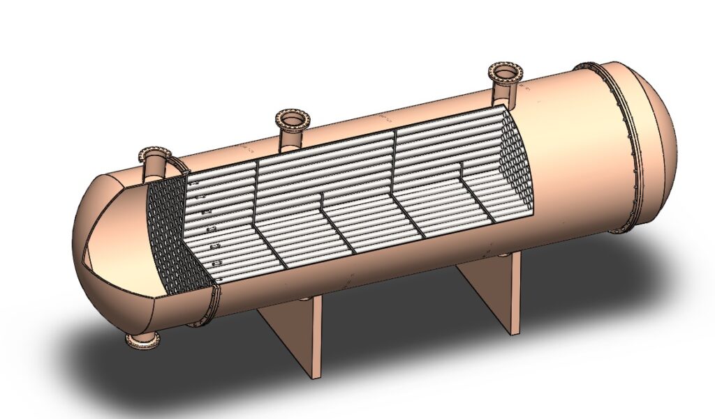
In a combined cycle CHP plant, the cooling and condensate systems are essential for managing the steam after it has passed through the steam turbine. These systems ensure that low-pressure steam or exhaust steam is safely condensed back into water for reuse in the Heat Recovery Steam Generator (HRSG), completing the steam cycle and maintaining efficient, continuous operation. Properly designed cooling and condensate systems also support thermal energy distribution for industrial processes or district heating, ensuring reliable supply of both electricity and heat.
The main function of the cooling system is to remove residual thermal energy from the exhaust steam leaving the turbine. This is typically achieved through steam condensers, which can be of various types, including surface condensers or air-cooled condensers. In surface condensers, exhaust steam passes over tubes containing cooling water, transferring heat and condensing the steam into liquid. The cooled water absorbs this heat and is either recirculated in a cooling tower or sent to a heat exchanger for industrial or district heating applications. Air-cooled condensers, on the other hand, transfer heat directly to ambient air using finned tubes and fans, which can be advantageous in water-scarce locations.
The condensate system collects the condensed water and pumps it back to the HRSG for reheating, maintaining a closed-loop cycle. Proper condensate handling is critical because the water must be treated to remove impurities and prevent corrosion, scaling, or fouling within the HRSG and turbine. Treatment systems often include filtration, deaeration to remove dissolved gases like oxygen, and chemical conditioning to maintain pH and prevent deposits. Maintaining high water quality ensures long-term efficiency, reduces maintenance costs, and prevents damage to heat exchange surfaces and turbine components.
Integration with district heating or industrial processes is another key aspect of cooling and condensate systems in CHP plants. In cogeneration applications, a portion of the steam can be extracted before condensation to supply hot water or process heat directly, while the remaining steam is condensed for reuse. This flexibility allows operators to balance electricity generation with thermal energy supply, optimizing overall plant efficiency and ensuring reliable delivery of both energy forms.
Cooling and condensate systems also include pumps, valves, heat exchangers, and control instrumentation to manage flow rates, pressures, and temperatures. Automated control ensures that condensers operate within design limits, steam is condensed efficiently, and the condensate is returned at the appropriate pressure and temperature for reheating. Real-time monitoring helps detect leaks, flow issues, or temperature deviations, enabling quick adjustments and preventing operational disruptions.
Maintenance and reliability are critical for these systems because any failure can reduce efficiency or interrupt both electricity and heat supply. Condensers, pumps, and piping are subject to thermal stress, corrosion, and mechanical wear. Routine inspections, cleaning, and preventive maintenance, along with continuous monitoring of water quality and system parameters, ensure long-term reliability and efficient operation.
Economically, efficient cooling and condensate systems reduce fuel consumption by enabling full recovery and reuse of water and steam within the HRSG. They minimize water usage, reduce thermal losses, and support the continuous supply of heat for industrial or district applications, enhancing the profitability of the CHP plant.
Environmentally, these systems help minimize water and energy waste. By condensing and recycling steam efficiently, the plant reduces the need for additional water or fuel, lowering carbon dioxide and pollutant emissions. In cogeneration applications, the integration of condensate systems with district heating networks further improves overall energy efficiency and reduces environmental impact.
In summary, cooling and condensate systems in a combined cycle CHP plant are critical for condensing turbine exhaust steam, recycling water to the HRSG, and distributing thermal energy for industrial or district heating use. Their design, operation, and integration with water treatment, control systems, and heat distribution ensure efficient, reliable, and environmentally sustainable operation of the CHP plant, supporting both electricity generation and heat supply.
In a combined cycle CHP plant, the cooling and condensate systems are essential for handling steam after it exits the steam turbine, ensuring efficient recovery, reuse, and distribution of thermal energy. Once the steam has passed through the turbine and delivered its energy, it must be condensed back into water to complete the cycle and allow continuous operation of the Heat Recovery Steam Generator (HRSG). Properly designed cooling and condensate systems not only maintain operational efficiency but also support thermal energy delivery for industrial processes or district heating.
The core of the cooling system is the condenser, where low-pressure exhaust steam is transformed back into liquid water. Surface condensers are commonly used, consisting of bundles of tubes carrying cooling water over which the steam flows, transferring its heat and condensing into water. The heated cooling water is then recirculated, often through cooling towers, or directed to heat exchangers for industrial use or district heating. In areas where water is scarce, air-cooled condensers may be employed, using fans and finned tubes to transfer heat directly to the ambient air.
The condensate system collects the condensed water and pumps it back to the HRSG for reheating, maintaining a closed-loop cycle. Water quality is critical in this process; dissolved gases, minerals, or impurities must be removed to prevent corrosion, scaling, or fouling in the HRSG and turbine components. Deaeration, filtration, and chemical treatment are commonly used to ensure high water quality, protecting equipment and maintaining efficiency.
Integration with cogeneration applications adds another layer of complexity. Steam can be extracted before condensation to supply process heat or district heating, while the remaining steam is condensed and returned to the HRSG. This flexibility allows operators to balance electricity generation with heat delivery, optimizing the plant’s overall efficiency and meeting variable energy demands.
Cooling and condensate systems include pumps, valves, heat exchangers, and control instrumentation to manage flow, pressure, and temperature. Automated control systems monitor these parameters to ensure the condenser operates efficiently, the condensate is returned at the correct conditions, and any deviations are corrected in real time. This helps prevent operational interruptions and ensures reliable electricity and heat production.
Maintenance is vital because condensers and associated equipment operate continuously under thermal stress and high pressure. Routine inspections, cleaning, and monitoring of water quality help prevent scaling, corrosion, or mechanical wear, ensuring long-term reliability and optimal efficiency.
Economically, efficient cooling and condensate systems reduce fuel consumption by enabling full reuse of water and steam, minimizing losses, and supporting reliable heat supply. Environmentally, these systems conserve water, reduce fuel usage, and lower emissions, enhancing the sustainability of the CHP plant.
In summary, the cooling and condensate systems in a combined cycle CHP plant are critical for condensing turbine exhaust steam, recycling it to the HRSG, and supporting thermal energy delivery for industrial or district heating applications. Their design, operation, and maintenance directly affect plant efficiency, reliability, and environmental performance, ensuring continuous and effective cogeneration of electricity and heat.
In a combined cycle CHP plant, cooling and condensate systems are essential for managing the steam after it has passed through the steam turbine. These systems condense the low-pressure exhaust steam back into water, allowing it to be returned to the Heat Recovery Steam Generator (HRSG) for reheating, thus completing the steam cycle and enabling continuous operation. Efficient design and operation of cooling and condensate systems are critical for maintaining high plant efficiency, supporting cogeneration, and ensuring reliable supply of both electricity and thermal energy.
The core component is the condenser, which removes residual thermal energy from the steam. Surface condensers are commonly used, where steam flows over tubes carrying cooling water, transferring its heat to the water and condensing into liquid. The heated water is then either recirculated through cooling towers or directed to heat exchangers for district heating or industrial applications. In regions where water is limited, air-cooled condensers are used, transferring heat directly to the ambient air via finned tubes and fans.
The condensate system collects the condensed water and pumps it back to the HRSG. Maintaining water quality is critical; impurities, dissolved gases, or minerals can cause corrosion, scaling, or fouling in the HRSG and turbines. Water treatment processes such as deaeration, filtration, and chemical conditioning are employed to ensure that the condensate is suitable for reuse, protecting equipment and sustaining efficiency.
Cooling and condensate systems are integrated with cogeneration processes. Steam can be extracted before condensation for use in district heating networks or industrial processes, while the remaining steam is condensed and returned to the HRSG. This allows operators to balance electricity and heat production to meet fluctuating demands, ensuring optimal overall efficiency.
Pumps, valves, heat exchangers, and automated control systems regulate flow, temperature, and pressure within the cooling and condensate circuits. Real-time monitoring ensures the condenser operates efficiently, steam is properly condensed, and condensate is returned under appropriate conditions. This coordination prevents operational disruptions and maintains stable electricity and heat output.
Maintenance is crucial, as condensers and related equipment operate under thermal stress and continuous pressure. Regular inspections, cleaning, and monitoring of water quality prevent corrosion, scaling, and mechanical wear, ensuring long-term reliability and consistent plant performance.
Economically, efficient cooling and condensate systems reduce fuel consumption by enabling full recovery and reuse of water and steam, minimizing losses, and supporting reliable heat supply. Environmentally, these systems conserve water, reduce energy waste, and lower emissions, enhancing the CHP plant’s sustainability.
In summary, cooling and condensate systems in a combined cycle CHP plant condense turbine exhaust steam, recycle it to the HRSG, and support the delivery of thermal energy for industrial or district heating use. Their design, operation, and maintenance are critical for ensuring efficient, reliable, and environmentally sustainable operation, enabling continuous cogeneration of electricity and heat.
Heat Distribution System
In a combined heat and power (CHP) plant, the heat distribution system is responsible for delivering the thermal energy generated by the plant to its intended end users, such as district heating networks, industrial processes, or domestic hot water systems. The system ensures that heat produced in the Heat Recovery Steam Generator (HRSG) or extracted from the steam turbine is efficiently transported and supplied at the correct temperature and pressure, maximizing the overall efficiency and utility of the cogeneration process. Properly designed heat distribution systems are crucial for maintaining consistent energy supply and minimizing thermal losses.
The core of the heat distribution system is typically a network of insulated pipes that carry hot water or steam from the CHP plant to the end users. For district heating applications, these networks can extend over several kilometers and are designed with supply and return lines to maintain continuous circulation. Insulation minimizes heat losses during transit, ensuring that the energy delivered is as close as possible to the energy produced. Flow rates, pressures, and temperatures are carefully controlled to match demand and maintain safe and efficient operation of both the CHP plant and the end-use systems.
In industrial applications, heat distribution systems may include dedicated piping, heat exchangers, and control valves to supply process heat at specific temperatures. Steam or hot water is delivered directly to industrial equipment, maintaining process efficiency while allowing the CHP plant to recover as much thermal energy as possible. Control systems adjust the flow of heat according to demand, preventing overheating, underheating, or unnecessary energy wastage.
Integration with condensate and cooling systems is critical for efficient operation. When steam is extracted for heating, the remaining low-pressure steam is often condensed, and the condensate is returned to the HRSG for reheating. This closed-loop system allows the plant to reuse water and heat efficiently, reducing fuel consumption and operational costs while maintaining consistent energy delivery.
Monitoring and control systems in the heat distribution network ensure safe and reliable operation. Sensors measure temperature, pressure, and flow at key points, and automated control systems adjust valves and pumps to maintain optimal conditions. These systems can also detect leaks, blockages, or inefficiencies, allowing rapid response to any issues that might disrupt heat delivery.
Maintenance of the heat distribution system is essential to prevent energy losses and ensure reliability. Insulation degradation, corrosion, or valve and pump failures can reduce efficiency or interrupt heat supply. Regular inspection, preventive maintenance, and replacement of worn components help maintain the system’s performance and extend its operational life.
Economically, an efficient heat distribution system maximizes the financial benefits of cogeneration by delivering the greatest possible amount of useful thermal energy from the CHP plant. By reducing losses and ensuring reliable heat delivery, the system supports industrial productivity, residential heating, and district heating operations, while lowering fuel consumption per unit of total energy output.
Environmentally, an effective heat distribution network reduces overall energy waste and associated emissions. By making full use of the thermal energy produced in the CHP plant, the system reduces the need for separate heat generation, which in turn lowers carbon dioxide and pollutant emissions and contributes to sustainable energy management.
In summary, the heat distribution system in a CHP plant is essential for transporting thermal energy from the HRSG or steam turbine to end users efficiently and reliably. By integrating insulated piping, control systems, condensate return loops, and monitoring equipment, the system ensures optimal energy use, operational flexibility, and environmental sustainability, enabling the CHP plant to deliver both electricity and heat efficiently and cost-effectively.
In a combined heat and power (CHP) plant, the heat distribution system is responsible for transporting the thermal energy generated by the plant to the end users, which may include district heating networks, industrial processes, or domestic hot water systems. The system ensures that the heat produced in the Heat Recovery Steam Generator (HRSG) or extracted from the steam turbine is delivered at the required temperature and pressure, allowing for efficient utilization of energy and maximizing the overall performance of the CHP plant. Properly designed heat distribution systems are critical for minimizing thermal losses, maintaining consistent supply, and supporting operational flexibility.
The heat distribution network typically consists of insulated supply and return pipelines that carry hot water or steam from the CHP plant to the end users. Insulation reduces heat losses during transit, ensuring that the energy delivered is as close as possible to the energy produced. Pumps, flow control valves, and expansion tanks are used to regulate flow rates, maintain pressure, and accommodate thermal expansion, ensuring that the system operates safely and efficiently under varying load conditions.
In industrial applications, the heat distribution system may include dedicated piping, heat exchangers, and temperature control mechanisms to deliver heat at specific parameters required for manufacturing processes. For district heating, the system usually incorporates supply and return circuits, balancing heat delivery to multiple buildings or facilities. Control systems monitor temperatures, pressures, and flow rates, adjusting valves and pumps automatically to match real-time demand, prevent overheating, and optimize energy use.
Integration with the condensate and cooling systems is essential for efficiency. When steam is extracted for heating purposes, the remaining steam can be condensed, and the resulting condensate is returned to the HRSG for reheating. This closed-loop design minimizes water consumption, reduces energy losses, and maintains high overall plant efficiency, ensuring that both electricity and heat are reliably delivered.
Monitoring and control play a key role in the heat distribution system. Sensors continuously measure temperature, pressure, and flow, enabling automated systems to adjust operation in real time. These systems also help detect leaks, blockages, or inefficiencies, allowing rapid response to prevent interruptions in heat supply.
Maintenance is critical for reliable operation. Corrosion, insulation degradation, valve or pump failures, and scaling in pipes or heat exchangers can reduce efficiency or interrupt heat delivery. Regular inspections, preventive maintenance, and timely replacement of worn components ensure long-term performance and consistent energy supply.
Economically, an efficient heat distribution system maximizes the value of the CHP plant by delivering the greatest amount of useful thermal energy with minimal losses. Efficient distribution reduces fuel consumption, supports industrial productivity, and provides reliable district heating, increasing the overall cost-effectiveness of the plant.
Environmentally, the system contributes to sustainability by minimizing wasted energy and reducing emissions. By utilizing the heat produced in the CHP plant efficiently, the need for separate heat generation is reduced, lowering carbon dioxide and other pollutant emissions.
In summary, the heat distribution system in a CHP plant is essential for transporting thermal energy from the HRSG or steam turbine to end users efficiently, safely, and reliably. Through insulated pipelines, control and monitoring systems, condensate return integration, and proper maintenance, the system ensures optimal energy use, operational flexibility, and environmental sustainability, enabling the CHP plant to deliver both electricity and heat effectively.
In a combined heat and power (CHP) plant, the heat distribution system is responsible for transporting the thermal energy produced by the plant to end users, such as district heating networks, industrial facilities, or domestic hot water systems. This system ensures that the heat recovered from the gas turbine exhaust through the Heat Recovery Steam Generator (HRSG) or extracted from the steam turbine reaches its destination at the required temperature and pressure, maximizing energy utilization and overall plant efficiency. Efficient heat distribution is essential for maintaining continuous operation, meeting variable demand, and minimizing thermal losses.
The system typically consists of insulated supply and return pipelines that carry hot water or steam from the CHP plant to the end users. Insulation is critical to reduce heat loss over long distances and maintain energy efficiency. Pumps, control valves, and expansion tanks regulate flow, maintain pressure, and accommodate thermal expansion, ensuring safe and reliable operation. For district heating, a looped supply and return network is commonly used to balance heat delivery across multiple buildings or facilities, while industrial heat distribution may involve dedicated piping and heat exchangers to deliver energy at precise temperatures for specific processes.
Integration with the condensate system is crucial in CHP plants. Steam extracted for heating purposes or industrial processes is often condensed after use, and the resulting condensate is returned to the HRSG for reheating. This closed-loop design conserves water, reduces fuel consumption, and ensures that thermal energy is used efficiently, contributing to higher overall plant performance.
Control and monitoring systems are essential for managing heat distribution effectively. Sensors measure temperature, pressure, and flow throughout the network, while automated controls adjust pumps, valves, and flow rates to match real-time demand. These systems also detect leaks, blockages, or inefficiencies, enabling rapid intervention and preventing disruptions in heat supply.
Maintenance of the heat distribution network is critical for reliability and efficiency. Insulation degradation, corrosion, valve or pump failures, and scaling in pipelines or heat exchangers can lead to energy losses or operational interruptions. Regular inspections, preventive maintenance, and timely replacement of worn components ensure consistent heat delivery and prolong system lifespan.
Economically, an efficient heat distribution system maximizes the value of the CHP plant by ensuring that the thermal energy produced is delivered with minimal losses. This reduces fuel consumption, lowers operating costs, and increases profitability while supporting industrial productivity and reliable district heating services.
Environmentally, the system reduces overall energy waste and lowers emissions. By efficiently transporting and utilizing heat generated in the CHP plant, the need for additional heat generation is minimized, reducing carbon dioxide and other pollutant emissions and contributing to sustainable energy management.
In summary, the heat distribution system in a CHP plant ensures that thermal energy recovered from the HRSG or steam turbine is efficiently, safely, and reliably delivered to end users. Its design, integration with condensate systems, control mechanisms, and maintenance practices are crucial for optimizing energy use, maintaining operational flexibility, and achieving economic and environmental sustainability in combined heat and power operations.
Control and Monitoring Systems
In a combined heat and power (CHP) plant, control and monitoring systems are essential for ensuring safe, efficient, and reliable operation of all plant components, including the gas turbine, steam turbine, Heat Recovery Steam Generator (HRSG), cooling and condensate systems, and the heat distribution network. These systems coordinate the generation of electricity and thermal energy, optimize fuel utilization, maintain process stability, and allow the plant to respond dynamically to changes in electricity or heat demand. Effective control and monitoring are critical for maximizing overall efficiency, preventing equipment damage, and maintaining compliance with operational and environmental standards.
Modern control systems in CHP plants are typically automated and integrated, using programmable logic controllers (PLCs), distributed control systems (DCS), or supervisory control and data acquisition (SCADA) platforms. These systems continuously monitor key parameters such as turbine speed, electrical output, steam temperature and pressure, feedwater levels, cooling water temperature, and flow rates throughout the plant. By processing this real-time data, the control system can adjust operating conditions, such as fuel flow to the gas turbine, steam extraction rates, or pump speeds, to maintain optimal performance under variable load conditions.
Safety is a primary function of control and monitoring systems. They continuously check critical operational limits and activate protective measures in the event of abnormal conditions, such as overpressure, overheating, excessive vibration, or loss of cooling. Automated shutdown sequences, alarms, and interlocks help prevent damage to expensive equipment like turbines, HRSGs, or condensers, ensuring the safety of personnel and the integrity of the plant.
Monitoring systems provide detailed performance data for operational analysis, predictive maintenance, and efficiency optimization. Parameters such as fuel consumption, heat rates, steam quality, and emission levels are recorded and analyzed to identify trends, detect potential issues, and plan maintenance activities. Predictive analytics can anticipate component wear or failures, allowing preventive maintenance that reduces unplanned downtime and extends the life of major plant equipment.
Integration with the heat distribution system is also a key role of control and monitoring systems. Real-time monitoring of heat supply, temperature, and flow ensures that the energy delivered to district heating networks or industrial processes meets demand without waste. The system can adjust steam extraction from the turbine or regulate flow in the distribution network, balancing electricity production and heat supply to optimize overall cogeneration efficiency.
Economically, control and monitoring systems improve plant profitability by maximizing fuel efficiency, reducing operational costs, minimizing downtime, and ensuring reliable energy delivery. Efficient operation also supports compliance with environmental regulations, reducing emissions and waste, which contributes to sustainability goals.
Maintenance of control and monitoring systems is essential to maintain reliability and accuracy. Regular calibration of sensors, updates to control software, testing of safety interlocks, and verification of communication networks ensure that the system continues to function effectively, supporting both operational performance and safety.
In summary, control and monitoring systems in a CHP plant are central to coordinating the operation of turbines, HRSG, condensers, and heat distribution networks. They provide real-time oversight, optimize performance, ensure safety, support predictive maintenance, and enable the plant to meet variable electricity and heat demands efficiently. By integrating operational control, monitoring, and automation, these systems ensure that a CHP plant operates reliably, economically, and sustainably, maximizing the combined production of electricity and thermal energy.
In a combined heat and power (CHP) plant, control and monitoring systems are critical for ensuring safe, efficient, and reliable operation across all plant components, including the gas turbine, steam turbine, Heat Recovery Steam Generator (HRSG), cooling and condensate systems, and heat distribution networks. These systems manage the simultaneous production of electricity and thermal energy, optimizing fuel use, maintaining process stability, and enabling the plant to respond dynamically to changing electricity or heat demands. Effective control and monitoring are essential for maximizing overall efficiency, protecting equipment, and ensuring environmental compliance.
Modern CHP plants use integrated control platforms, often based on distributed control systems (DCS), programmable logic controllers (PLCs), or supervisory control and data acquisition (SCADA) systems. These platforms continuously collect real-time data on key parameters such as turbine speed, electrical output, steam pressure and temperature, feedwater levels, cooling water flow and temperature, and heat distribution metrics. The system uses this information to automatically adjust operating conditions—such as fuel supply, steam extraction, or pump speed—ensuring optimal performance under varying load conditions.
Safety is a primary function of control and monitoring systems. They constantly monitor operational limits and activate protective measures when abnormal conditions arise, including overpressure, overheating, excessive vibration, or cooling system failures. Automated interlocks, alarms, and emergency shutdown sequences help prevent damage to turbines, HRSG units, condensers, or other critical equipment, protecting both the plant and personnel.
Monitoring systems also support operational analysis and predictive maintenance. Data on fuel consumption, heat rates, steam quality, and emission levels is recorded and analyzed to identify trends, detect inefficiencies, and anticipate component wear. Predictive maintenance enabled by this data helps prevent unplanned downtime, extends equipment life, and improves overall plant reliability.
Integration with heat distribution is another key function. Control systems regulate steam extraction from the turbine and flow through the district heating or industrial networks to meet real-time demand while maintaining electricity generation efficiency. This ensures a balanced output of electricity and thermal energy, optimizing overall cogeneration performance.
Economically, control and monitoring systems enhance plant profitability by improving fuel efficiency, minimizing operational disruptions, and reducing maintenance costs. Environmentally, these systems help reduce emissions and energy waste by ensuring that all plant processes operate within design parameters and that energy recovery is maximized.
Maintenance of control and monitoring systems is vital to sustain accuracy and reliability. Regular calibration of sensors, software updates, testing of safety interlocks, and verification of communication networks ensure continuous, reliable operation.
In summary, control and monitoring systems in a CHP plant provide centralized management, real-time oversight, and automated control of turbines, HRSGs, condensers, and heat distribution networks. They ensure safe, efficient, and flexible operation, optimize energy output, support predictive maintenance, and help achieve economic and environmental performance goals, enabling the plant to reliably deliver both electricity and heat.
In a combined heat and power (CHP) plant, control and monitoring systems are essential for ensuring that all plant components operate safely, efficiently, and reliably. These systems coordinate the operation of the gas turbine, steam turbine, Heat Recovery Steam Generator (HRSG), cooling and condensate systems, and heat distribution network. Their primary function is to optimize the simultaneous production of electricity and thermal energy, maximize fuel utilization, maintain system stability, and respond dynamically to changes in electricity or heat demand. Proper control and monitoring are crucial for maintaining high efficiency, protecting equipment, and ensuring compliance with environmental and operational standards.
Modern CHP plants rely on integrated control platforms such as distributed control systems (DCS), programmable logic controllers (PLCs), or supervisory control and data acquisition (SCADA) systems. These platforms continuously collect data on key parameters, including turbine speed, electrical output, steam temperature and pressure, feedwater levels, cooling water flow and temperature, and heat distribution metrics. Using this data, the control system automatically adjusts operating conditions, such as fuel supply, steam extraction rates, or pump speeds, to maintain optimal performance under varying load conditions.
Safety is a core function of control and monitoring systems. They continuously check for abnormal conditions such as overpressure, overheating, excessive vibration, or failure in cooling systems, and trigger protective actions when necessary. Automated interlocks, alarms, and emergency shutdown sequences prevent damage to critical equipment like turbines, HRSG units, or condensers, ensuring both plant safety and personnel protection.
Monitoring functions also support performance optimization and predictive maintenance. Detailed data on fuel consumption, heat rates, steam quality, and emissions is analyzed to identify trends, detect inefficiencies, and anticipate component wear. Predictive maintenance enabled by this data reduces unplanned downtime, extends equipment lifespan, and improves overall plant reliability.
Integration with the heat distribution system is another critical aspect. Control systems regulate steam extraction from the turbine and flow through district heating or industrial networks to meet real-time demand, while maintaining electricity generation efficiency. This ensures a balanced supply of electricity and thermal energy, optimizing overall cogeneration performance.
Economically, these systems improve plant profitability by enhancing fuel efficiency, reducing operational disruptions, and minimizing maintenance costs. Environmentally, they reduce emissions and energy waste by ensuring that all processes operate within design parameters and that energy recovery is maximized.
Maintenance of control and monitoring systems is essential to ensure ongoing accuracy and reliability. This includes regular calibration of sensors, software updates, testing of safety interlocks, and verification of communication networks.
In summary, control and monitoring systems in a CHP plant provide centralized oversight, real-time management, and automated control of turbines, HRSGs, condensers, and heat distribution networks. They ensure safe, efficient, and flexible operation, optimize energy output, support predictive maintenance, and help the plant meet both economic and environmental performance objectives, enabling continuous and reliable delivery of electricity and heat.
Steam Turbine CHP Plants
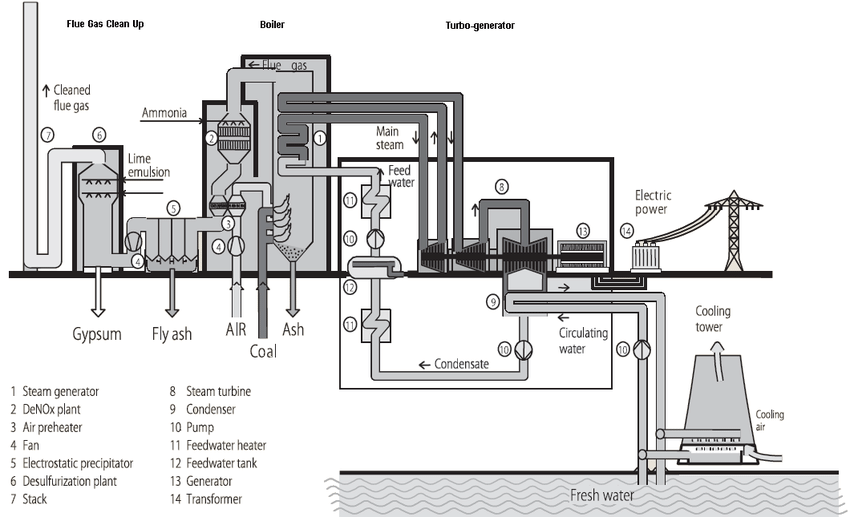
Steam turbine CHP plants are a type of combined heat and power (CHP) facility in which the primary source of electricity and thermal energy is a steam turbine. In these plants, fuel—typically natural gas, coal, biomass, or waste-derived fuels—is combusted in a boiler or furnace to generate high-pressure, high-temperature steam. This steam drives the blades of a steam turbine, converting thermal energy into mechanical energy, which is then converted into electricity by an attached generator. Simultaneously, a portion of the steam is extracted or used after expansion to provide thermal energy for industrial processes, district heating, or other applications, making steam turbine CHP plants effective for cogeneration.
The design of a steam turbine CHP plant focuses on maximizing overall efficiency by capturing as much energy from the fuel as possible. High-pressure steam enters the turbine and expands through multiple stages—typically high-pressure (HP), intermediate-pressure (IP), and low-pressure (LP) sections—allowing efficient conversion of thermal energy into mechanical energy. The steam can be extracted at intermediate stages to supply heat at the desired temperature for industrial or district heating applications, while the remaining steam continues through the turbine for electricity generation. This staged extraction provides operational flexibility to balance electricity production with heat supply according to demand.
The boiler or steam generator is a central component, producing steam at controlled temperature and pressure. Fuel combustion in the boiler must be carefully managed to ensure optimal steam quality and minimize emissions. Advanced steam turbines are designed to handle variations in steam flow and pressure, allowing the CHP plant to respond to fluctuating electricity and thermal energy demands efficiently.
Condensers and condensate systems play a crucial role in these plants. After steam passes through the turbine, it is either extracted for heating or condensed into water for return to the boiler, completing the cycle. Cooling water or air removes residual heat from the exhaust steam, while treated condensate is pumped back to the boiler. Efficient condensate recovery reduces water consumption, improves plant efficiency, and lowers operating costs.
Control and monitoring systems are essential for the safe and efficient operation of steam turbine CHP plants. These systems continuously track key parameters, including steam pressure and temperature, turbine speed, generator output, and heat supply, and they automatically adjust fuel input, steam extraction, and flow rates to optimize performance. Safety interlocks and alarms protect the plant from overpressure, overheating, or other abnormal conditions, while monitoring systems support predictive maintenance and performance optimization.
Economically, steam turbine CHP plants provide significant benefits by producing both electricity and useful heat from a single fuel source. This dual output reduces fuel costs per unit of energy and increases overall energy efficiency, often reaching total efficiencies of 70–80 percent. Environmentally, these plants reduce greenhouse gas emissions and pollutant output by maximizing energy extraction from fuel and reducing the need for separate heat generation.
In summary, steam turbine CHP plants are highly efficient cogeneration facilities that convert fuel energy into both electricity and useful heat. Their design incorporates advanced boilers, multi-stage turbines, condensers, and control systems to optimize energy conversion, enable flexible heat extraction, ensure operational reliability, and provide economic and environmental benefits. These plants are particularly suitable for industrial facilities, district heating networks, and applications where simultaneous production of electricity and thermal energy is required.
Steam turbine CHP plants consist of several main components, each essential for converting fuel into electricity and useful heat while ensuring efficient, safe, and reliable operation. The primary parts include the boiler or steam generator, steam turbine, electric generator, condensers and cooling system, pumps and feedwater system, steam and heat extraction system, and control and monitoring systems.
The boiler or steam generator is where fuel combustion occurs to produce high-pressure, high-temperature steam. The boiler must be designed to generate steam at the required temperature and pressure for the turbine while maintaining efficiency and minimizing emissions. Various fuels can be used, including natural gas, coal, biomass, or waste-derived fuels, depending on plant design and availability.
The steam turbine converts thermal energy from the high-pressure steam into mechanical energy. Modern turbines typically have multiple pressure stages—high-pressure (HP), intermediate-pressure (IP), and low-pressure (LP)—allowing efficient energy extraction. Steam can also be extracted at intermediate points for industrial or district heating applications, providing operational flexibility in cogeneration.
The electric generator is mechanically coupled to the steam turbine and converts the turbine’s rotational energy into electrical energy. The generator is sized and synchronized to match the turbine output and the grid or local electricity requirements.
Condensers and the cooling system remove residual heat from the exhaust steam after it passes through the turbine. Surface or air-cooled condensers condense steam back into water, which is then collected in the condensate and feedwater system. Pumps return the condensate to the boiler for reheating, creating a closed-loop cycle that conserves water and improves overall efficiency.
The steam and heat extraction system allows controlled diversion of steam from the turbine for use in district heating networks or industrial processes. This system ensures that thermal energy is delivered at the correct temperature and pressure, enabling the CHP plant to provide flexible and reliable heat supply while maintaining electricity generation.
Finally, control and monitoring systems integrate all components, ensuring safe, efficient, and optimized operation. Sensors and automated controls track steam pressures, temperatures, turbine speed, electrical output, and heat supply, adjusting fuel flow, steam extraction, and pump operation to maintain stable and efficient performance. These systems also provide safety interlocks, alarms, and predictive maintenance support to protect equipment and optimize plant operation.
In summary, the main parts of a steam turbine CHP plant include the boiler, steam turbine, electric generator, condensers and cooling system, condensate and feedwater system, steam and heat extraction network, and control and monitoring systems. Together, these components enable the plant to produce electricity and useful heat efficiently, reliably, and sustainable
1. Boiler or Steam Generator
The boiler or steam generator is where fuel combustion occurs to produce high-pressure, high-temperature steam. It must deliver steam at the required temperature and pressure for the turbine while maintaining efficiency and minimizing emissions. Fuels used can include natural gas, coal, biomass, or waste-derived fuels, depending on plant design and availability.
2. Steam Turbine
The steam turbine converts thermal energy from high-pressure steam into mechanical energy. Modern turbines often include multiple pressure stages—high-pressure (HP), intermediate-pressure (IP), and low-pressure (LP)—for efficient energy extraction. Steam can be extracted at intermediate points for industrial or district heating, providing flexibility in balancing electricity generation with thermal energy supply.
3. Electric Generator
The electric generator is mechanically coupled to the steam turbine and converts the turbine’s rotational energy into electrical energy. It is designed to match the turbine output and synchronize with the electricity grid or local power requirements.
4. Condensers and Cooling System
Condensers remove residual heat from the exhaust steam after it passes through the turbine. Surface or air-cooled condensers condense the steam into water, allowing it to be collected and returned to the boiler. The cooling system ensures efficient heat removal and maintains operational stability.
5. Condensate and Feedwater System
The condensate and feedwater system collects condensed water from the condensers and pumps it back to the boiler for reheating. This closed-loop cycle conserves water, improves overall efficiency, and ensures continuous steam supply for the turbine.
6. Steam and Heat Extraction System
This system allows controlled extraction of steam from the turbine for district heating networks or industrial processes. It delivers thermal energy at the required temperature and pressure, enabling cogeneration while maintaining electricity output.
7. Control and Monitoring Systems
Control and monitoring systems integrate all plant components, ensuring safe, efficient, and optimized operation. They continuously monitor turbine speed, steam pressure and temperature, electrical output, and heat supply, automatically adjusting fuel flow, steam extraction, and pump operation. These systems also provide safety interlocks, alarms, and predictive maintenance support.
Boiler or Steam Generator
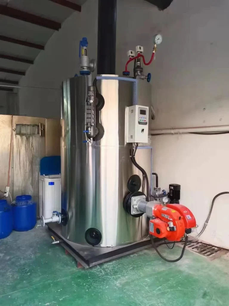
The boiler, also called a steam generator, is the heart of a steam turbine CHP plant. Its primary function is to convert the chemical energy of the fuel into thermal energy by producing high-pressure, high-temperature steam. This steam is then used to drive the steam turbine for electricity generation and to provide thermal energy for industrial processes or district heating applications.
Fuel combustion in the boiler can involve a variety of sources, including natural gas, coal, biomass, or waste-derived fuels. The choice of fuel affects boiler design, efficiency, and emissions control strategies. Modern CHP boilers are designed for high efficiency, often incorporating features like economizers, superheaters, and reheaters to maximize energy extraction from the fuel.
The steam produced in the boiler must meet precise pressure and temperature requirements to ensure optimal turbine performance. Superheated steam is typically used to prevent condensation in the turbine blades, which could cause erosion or reduce efficiency. The boiler is equipped with safety systems such as pressure relief valves, water level controls, and automatic shutoff mechanisms to prevent accidents and maintain stable operation.
In cogeneration applications, the boiler’s design may include provisions for extracting steam at intermediate pressures for district heating or industrial use. This requires careful balancing to maintain sufficient steam flow and pressure for electricity generation while delivering thermal energy at the required temperature and quantity.
Efficient combustion and heat transfer within the boiler are crucial for overall plant performance. Modern boilers incorporate advanced control systems to regulate fuel and air flow, monitor combustion conditions, and maintain steam quality. These systems ensure high thermal efficiency, reduce fuel consumption, and minimize emissions such as NOx, SOx, and particulate matter.
In summary, the boiler or steam generator is the component in a steam turbine CHP plant that produces high-pressure, high-temperature steam from fuel combustion. It serves as the foundation for both electricity generation and heat supply, and its design, efficiency, and operational control are critical to the overall performance, safety, and environmental compliance of the CHP plant.
The boiler, also known as the steam generator, is the primary component in a steam turbine CHP plant where fuel energy is converted into high-pressure, high-temperature steam. This steam is used both to drive the steam turbine for electricity generation and to provide thermal energy for industrial processes or district heating applications, making the boiler a central element in cogeneration.
Fuel combustion in the boiler can involve natural gas, coal, biomass, or waste-derived fuels. The choice of fuel affects the boiler’s design, efficiency, and emissions control requirements. Modern boilers are designed to maximize heat transfer and overall efficiency, often incorporating superheaters, reheaters, economizers, and advanced burners to optimize energy extraction from the fuel.
The steam produced must meet precise pressure and temperature requirements to ensure safe and efficient operation of the steam turbine. Superheated steam is typically used to prevent condensation in turbine blades, which can cause erosion or reduce performance. Boilers are equipped with safety features, including pressure relief valves, water level controls, and automatic shutdown systems, to protect the plant and personnel from hazardous conditions.
In CHP applications, the boiler may be designed to support steam extraction at intermediate pressures for heating purposes while maintaining sufficient steam flow for electricity generation. This requires careful balancing to optimize both electricity output and thermal energy supply.
Efficient combustion and heat transfer are supported by automated control systems that regulate fuel and air flow, monitor flame stability, and ensure consistent steam quality. These systems also help reduce emissions of pollutants such as NOx, SOx, and particulates, contributing to environmental compliance and sustainable operation.
In summary, the boiler or steam generator is the component that produces the steam necessary for both electricity generation and heat supply in a steam turbine CHP plant. Its design, operational control, and efficiency are fundamental to the plant’s overall performance, safety, and environmental impact.
The boiler, or steam generator, is the core component of a steam turbine CHP plant, responsible for producing high-pressure, high-temperature steam from the combustion of fuel. This steam serves a dual purpose: driving the steam turbine to generate electricity and providing thermal energy for industrial processes or district heating, making it central to the cogeneration process.
Boilers can operate on a variety of fuels, including natural gas, coal, biomass, or waste-derived fuels. The choice of fuel influences the boiler’s design, efficiency, and emissions management. Modern boilers are engineered for high thermal efficiency and often include features such as superheaters, reheaters, economizers, and advanced combustion controls to maximize energy extraction from the fuel.
Steam produced in the boiler must meet precise pressure and temperature specifications to ensure optimal turbine performance. Superheated steam is typically used to prevent condensation within the turbine, which could damage blades and reduce efficiency. The boiler is equipped with safety systems such as pressure relief valves, automatic shutdown mechanisms, and water level controls to ensure safe and stable operation.
In cogeneration applications, boilers are often designed to allow steam extraction at intermediate pressures to supply heat for industrial or district heating applications while maintaining adequate steam flow for electricity generation. This flexibility enables the plant to balance electricity production with heat supply efficiently.
Advanced control systems regulate fuel and air flow, monitor combustion stability, and maintain consistent steam quality, ensuring high efficiency and reduced emissions. These systems also support compliance with environmental regulations by minimizing pollutants such as NOx, SOx, and particulate matter.
In summary, the boiler or steam generator in a steam turbine CHP plant produces the steam that drives electricity generation and delivers useful heat. Its design, efficiency, safety features, and operational controls are critical to the overall performance, reliability, and environmental sustainability of the plant.
Steam Turbine
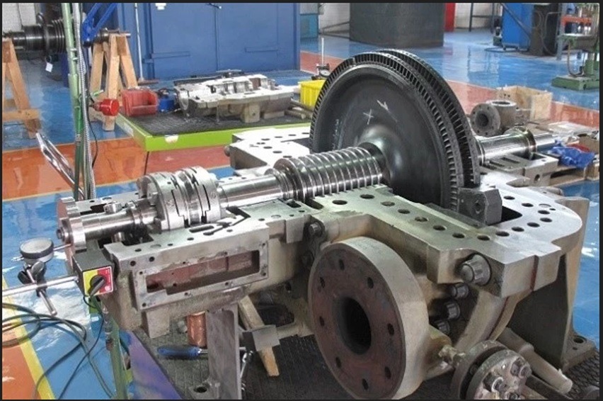
The steam turbine is a central component in a steam turbine CHP plant, responsible for converting thermal energy from high-pressure steam into mechanical energy, which is then transformed into electricity by the coupled generator. It is also a key element in the cogeneration process, as it allows the extraction of steam at different pressures to supply heat for industrial processes or district heating while generating electricity simultaneously.
High-pressure steam produced in the boiler enters the turbine and expands through multiple stages of rotor blades, transferring its energy into rotational mechanical motion. Modern steam turbines are typically divided into high-pressure (HP), intermediate-pressure (IP), and low-pressure (LP) sections, allowing staged energy extraction and maximizing efficiency. The design ensures that the thermal energy in the steam is effectively converted into mechanical energy before the remaining steam is either condensed or used for heating purposes.
In cogeneration applications, the steam turbine provides flexibility through controlled steam extraction. Steam can be drawn from the HP or IP stages to supply process heat or district heating networks, while the remaining steam continues to expand for electricity generation. This flexibility enables the plant to adjust the ratio of electricity to heat output according to real-time demand, maintaining high overall efficiency.
Materials and construction of steam turbines are critical for performance and reliability. Rotors, blades, and casings are made from high-strength, heat-resistant alloys to withstand high temperatures, pressures, and potential impurities in the steam. Advanced aerodynamic blade designs improve energy conversion, reduce losses, and extend service life. Bearings, seals, and cooling systems are incorporated to maintain stability and prevent wear during continuous operation.
Control and monitoring systems regulate turbine speed, steam flow, and pressure to optimize performance and ensure safe operation. Automated systems can adjust the turbine operation in response to changes in electricity demand or steam extraction requirements, preventing mechanical stress and maintaining efficiency.
Maintenance is crucial for long-term operation. Steam turbines are subject to thermal fatigue, erosion, and mechanical wear. Regular inspections, monitoring of vibration and temperature, and preventive maintenance of blades, seals, and bearings ensure reliability and efficiency.
In summary, the steam turbine in a CHP plant converts thermal energy from high-pressure steam into mechanical energy for electricity generation while allowing flexible extraction of steam for heating applications. Its design, materials, staged expansion, and integration with control systems are essential for maximizing efficiency, reliability, and overall performance in cogeneration.
The steam turbine is a critical component of a steam turbine CHP plant, converting thermal energy from high-pressure steam into mechanical energy that drives the electric generator. In cogeneration applications, it also enables the extraction of steam at intermediate pressures to provide heat for industrial processes or district heating, making it a central element in combined heat and power production.
High-pressure steam from the boiler enters the turbine and expands through multiple stages of rotor blades, transferring energy into rotational motion. Modern steam turbines are usually divided into high-pressure (HP), intermediate-pressure (IP), and low-pressure (LP) sections. This multi-stage design maximizes energy conversion efficiency and allows the plant to extract steam for heating without compromising electricity production.
Steam extraction points provide operational flexibility, enabling the plant to adjust the balance between electricity generation and thermal energy supply according to demand. The remaining steam continues through the turbine for further expansion, after which it is either condensed in the cooling system or used for low-pressure heating applications.
Steam turbines are constructed from high-strength, heat-resistant materials to withstand extreme pressures and temperatures. Blade design, rotor construction, and precision engineering ensure efficient energy conversion and long service life. Bearings, seals, and cooling systems are incorporated to maintain stability and prevent wear during continuous operation.
Control and monitoring systems regulate turbine speed, steam flow, and extraction rates, ensuring safe operation and optimal performance. These systems respond dynamically to changing electricity and heat demands, maintaining efficiency while preventing mechanical stress or thermal overload.
Regular maintenance is essential for reliability. Turbines are subject to thermal fatigue, erosion, and wear on blades and bearings. Scheduled inspections, vibration monitoring, and preventive maintenance help maintain performance, prevent unplanned downtime, and extend equipment life.
In summary, the steam turbine in a CHP plant transforms high-pressure steam into mechanical energy for electricity generation while enabling flexible heat extraction for cogeneration. Its staged design, material construction, control systems, and maintenance practices are crucial for efficient, reliable, and sustainable plant operation.
The steam turbine is a key component in a steam turbine CHP plant, converting the thermal energy of high-pressure steam into mechanical energy, which is then used to drive an electric generator. In cogeneration applications, it also allows for the extraction of steam at various pressures to provide heat for industrial processes or district heating, making it central to combined heat and power production.
High-pressure steam produced in the boiler enters the turbine and expands through multiple stages of rotor blades, transferring its energy into rotational motion. Modern steam turbines typically include high-pressure (HP), intermediate-pressure (IP), and low-pressure (LP) sections, which enable efficient energy conversion and allow staged steam extraction for heat supply without significantly affecting electricity generation.
The turbine provides operational flexibility by allowing controlled extraction of steam at intermediate points for heating purposes. The remaining steam continues through the turbine, expanding further to generate electricity, before being condensed in the cooling system or reused for low-pressure heating applications.
Construction of steam turbines involves high-strength, heat-resistant materials that withstand extreme temperatures and pressures. Blade design, rotor engineering, and precision manufacturing optimize energy conversion, efficiency, and durability. Bearings, seals, and internal cooling systems maintain stability and prevent wear during continuous operation.
Control and monitoring systems regulate turbine speed, steam flow, and extraction rates to ensure safe, efficient, and stable operation. These systems automatically adjust turbine parameters in response to changes in electricity or heat demand, maintaining performance while protecting the equipment from mechanical or thermal stress.
Maintenance is critical to ensure long-term reliability. Turbines are subject to thermal fatigue, erosion, and wear on blades and bearings. Routine inspections, vibration monitoring, and preventive maintenance help maintain efficiency, prevent unexpected downtime, and extend operational life.
In summary, the steam turbine in a CHP plant converts high-pressure steam into mechanical energy for electricity generation while enabling flexible heat extraction for cogeneration. Its staged design, material construction, operational controls, and maintenance practices are essential for achieving efficient, reliable, and sustainable operation.
The electric generator is a crucial component of a steam turbine CHP plant, responsible for converting the mechanical energy produced by the steam turbine into electrical energy for distribution and use. In cogeneration systems, the generator works in tandem with the steam turbine, ensuring that electricity is produced efficiently while simultaneously allowing steam to be extracted for heating or industrial processes.
The generator is mechanically coupled to the turbine rotor, so as the turbine spins, it drives the generator’s rotor within a magnetic field, inducing an electric current in the stator windings. Depending on the plant design and scale, generators may be designed for medium- or high-voltage output and are synchronized with the local electrical grid or the plant’s internal distribution network. Efficiency and reliability of the generator are critical, as any energy losses directly impact the overall performance of the CHP plant.
Modern generators in CHP plants are typically of the synchronous type, which allows precise control of frequency and voltage. They are equipped with cooling systems—air-cooled or water-cooled—to manage the heat generated during operation and maintain safe operating temperatures. Bearings, insulation, and other components are designed to withstand mechanical stresses and thermal loads over long-term continuous operation.
Control and monitoring systems ensure optimal generator performance. Sensors continuously monitor electrical parameters such as voltage, current, frequency, and power output, while automated systems can adjust excitation and load distribution to maintain stability and protect the generator from overload or faults. Integration with the turbine control system allows seamless operation, adjusting power output according to steam supply and demand conditions.
Maintenance is essential for long-term reliability. Routine inspections, lubrication, cleaning, and testing of insulation and bearings help prevent failures and reduce downtime. Predictive maintenance using performance monitoring data can also detect potential issues before they lead to costly repairs or operational interruptions.
In summary, the electric generator in a steam turbine CHP plant converts mechanical energy from the turbine into electrical energy while working in coordination with steam extraction for cogeneration. Its design, cooling, control, and maintenance are critical for ensuring efficient, reliable, and safe electricity production alongside thermal energy supply.
The electric generator in a steam turbine CHP plant is responsible for converting the mechanical energy produced by the turbine into electrical energy for use on-site or for distribution to the grid. It is mechanically coupled to the turbine rotor, so as the turbine spins, the generator rotor rotates within a magnetic field, inducing an electric current in the stator windings. This transformation of mechanical to electrical energy is central to the CHP process, allowing the plant to produce electricity while simultaneously providing thermal energy for industrial processes or district heating.
Modern CHP plants typically use synchronous generators, which provide precise control of voltage and frequency and ensure stable integration with the electrical grid. Depending on the plant size and capacity, generators can be designed for medium- or high-voltage output. To maintain efficiency and prevent overheating, generators are equipped with cooling systems, which may be air-cooled or water-cooled, managing the thermal load generated during continuous operation. Bearings, insulation, and rotor components are engineered to withstand mechanical stress and thermal expansion, ensuring long-term reliability.
Control and monitoring systems are integral to generator operation. Electrical parameters such as voltage, current, frequency, and power output are continuously measured, and automated systems adjust excitation, load distribution, or turbine speed to maintain optimal performance. This integration allows the generator to respond dynamically to changes in electricity demand or steam supply, ensuring that both electricity and thermal energy are delivered efficiently.
Maintenance plays a critical role in sustaining generator performance and reliability. Routine inspections, cleaning, lubrication of bearings, and testing of insulation are conducted to prevent unexpected failures. Predictive maintenance, enabled by monitoring system data, helps identify early signs of wear or faults, minimizing downtime and extending the lifespan of the generator.
Overall, the electric generator is a vital component in a steam turbine CHP plant, transforming mechanical energy into electrical power while working in coordination with the turbine and steam extraction systems. Its efficiency, control, and maintenance directly affect the plant’s ability to deliver reliable electricity alongside usable thermal energy, ensuring both economic and operational performance.
The electric generator in a steam turbine CHP plant plays a central role in converting the rotational mechanical energy of the turbine into usable electrical energy. As the turbine spins, the rotor of the generator rotates within a magnetic field, inducing an electrical current in the stator windings. This process allows the plant to produce electricity efficiently while simultaneously supplying steam for heating or industrial applications, making it a core component of cogeneration.
Generators in modern CHP plants are usually synchronous machines, which provide precise control over voltage and frequency, ensuring stable connection with the electrical grid. Depending on the plant’s design and capacity, generators may operate at medium or high voltage and are designed for continuous operation under heavy thermal and mechanical loads. Cooling systems, either air-cooled or water-cooled, are used to dissipate heat generated during operation, maintaining optimal operating temperatures and preventing damage to windings and insulation.
The performance of the generator is closely integrated with the turbine and control systems. Sensors continuously monitor electrical parameters such as voltage, current, frequency, and power output, while automated control systems adjust excitation, load distribution, or turbine speed to maintain efficiency and stability. This integration allows the generator to respond dynamically to changes in electricity demand and fluctuations in steam supply from the turbine, ensuring a reliable balance of electricity and thermal energy output.
Maintenance is essential to the long-term reliability of the generator. Bearings, insulation, cooling systems, and other components are regularly inspected and maintained to prevent failures. Predictive maintenance strategies, supported by monitoring data, help identify potential issues before they affect performance, reducing unplanned downtime and extending the operational life of the generator.
In summary, the electric generator is a critical element in a steam turbine CHP plant, transforming mechanical energy into electrical energy while coordinating with the turbine and heat extraction systems. Its efficiency, reliability, and integration with control systems are vital for delivering both electricity and useful thermal energy, supporting the economic and operational success of the cogeneration plant.
Condensers and Cooling System
The condensers and cooling system in a steam turbine CHP plant are essential for managing the residual heat of the steam after it has passed through the turbine. Once the steam has expanded and transferred most of its energy to the turbine blades, it still contains latent heat that must be removed before it can be returned to the boiler as feedwater. The condenser cools and condenses this exhaust steam into water, completing the thermodynamic cycle and enabling efficient reuse of water in the system. This process is critical for maintaining continuous plant operation, conserving water, and maximizing overall thermal efficiency.
Condensers are typically of the surface type, where steam flows over tubes carrying cooling water, or air-cooled types, where steam is condensed by ambient air using large heat exchangers. The choice between water-cooled and air-cooled systems depends on water availability, environmental conditions, and plant design requirements. Water-cooled condensers often use circulating water from nearby sources or cooling towers, while air-cooled condensers rely on fans to move air across finned tubes, making them suitable for areas with limited water resources.
The cooling system not only condenses steam but also removes excess heat from other components of the plant, such as turbine bearings, generator windings, and auxiliary systems. Proper design ensures that heat is efficiently transferred away from the system, maintaining optimal operating temperatures and preventing equipment damage. Pumps circulate the cooling water continuously, and heat exchangers or cooling towers dissipate the absorbed heat to the environment.
Integration with the condensate and feedwater system is vital. After condensation, the water collected in the condenser is returned to the boiler as feedwater, creating a closed-loop system that reduces water consumption and improves energy efficiency. The temperature and quality of the condensate are carefully controlled to prevent corrosion, scaling, and turbine damage.
Control and monitoring systems play a key role in maintaining the performance of condensers and cooling systems. Sensors measure water flow, temperature, and pressure, while automated controls adjust pump speeds, cooling tower fan operation, and bypass valves to maintain efficient condensation and heat removal under varying load conditions. These systems also detect leaks, blockages, or equipment malfunctions, enabling rapid response and preventing operational disruptions.
Maintenance is critical for long-term reliability. Condenser tubes, cooling water pumps, and heat exchangers are subject to corrosion, scaling, and fouling, which can reduce heat transfer efficiency and plant performance. Regular inspection, cleaning, and preventive maintenance ensure that the cooling system operates at peak efficiency and supports continuous, reliable CHP operation.
In summary, the condensers and cooling system in a steam turbine CHP plant remove residual heat from the exhaust steam, condense it into water for reuse, and dissipate excess heat from auxiliary systems. Proper design, integration with the feedwater loop, control systems, and maintenance are essential for efficiency, reliability, and sustainable operation, enabling the plant to deliver both electricity and thermal energy effectively.
The condensers and cooling system in a steam turbine CHP plant play a critical role in managing the residual energy of the steam after it has passed through the turbine. As the steam exits the turbine, it still contains latent heat that must be removed before it can be returned to the boiler as feedwater. The condenser performs this function by cooling the steam and converting it back into liquid water, completing the thermodynamic cycle and allowing the water to be reused. Efficient condensation is essential for maintaining continuous operation, conserving water, and maximizing the overall thermal efficiency of the plant.
Condensers are commonly designed as surface-type heat exchangers, where the steam flows over tubes carrying cooling water, or as air-cooled systems that rely on ambient air to condense the steam. Water-cooled condensers typically use circulating water from nearby sources or cooling towers to transfer heat, while air-cooled condensers employ large fans to move air across finned tubes. The choice of condenser type depends on the availability of water, environmental conditions, and specific plant design considerations.
The cooling system not only condenses exhaust steam but also removes heat from other plant components such as turbine bearings, generator windings, and auxiliary systems. Pumps continuously circulate cooling water, and heat exchangers or cooling towers dissipate the absorbed heat into the environment. Proper design and operation ensure that equipment remains within safe temperature ranges, preventing overheating and maintaining reliability.
Integration with the condensate and feedwater system is essential for efficiency. Once the steam has been condensed, the water is collected and returned to the boiler as feedwater, creating a closed-loop cycle that minimizes water consumption and improves energy utilization. Maintaining the correct temperature and water quality is crucial to prevent corrosion, scaling, and damage to the turbine and boiler.
Control and monitoring systems are integral to the performance of condensers and cooling systems. Sensors continuously track water flow, temperature, and pressure, while automated systems adjust pump speeds, fan operation, and bypass valves to maintain optimal condensation and heat removal. These systems can also detect leaks, blockages, or equipment malfunctions, enabling rapid corrective action to avoid disruptions in plant operation.
Regular maintenance is vital for sustaining efficiency and reliability. Condenser tubes, pumps, and heat exchangers are prone to fouling, scaling, and corrosion, which can reduce heat transfer efficiency and overall plant performance. Routine inspections, cleaning, and preventive maintenance ensure that the cooling system operates effectively, supporting continuous electricity generation and thermal energy supply.
In conclusion, the condensers and cooling system in a steam turbine CHP plant are essential for removing residual heat from exhaust steam, converting it back into feedwater, and dissipating excess heat from auxiliary equipment. Their design, integration with the feedwater loop, automated controls, and maintenance practices are critical for maximizing plant efficiency, reliability, and sustainability while ensuring the effective delivery of both electricity and thermal energy.
The condensers and cooling system in a steam turbine CHP plant are vital for maintaining the efficiency and continuous operation of the plant. After the steam passes through the turbine, it still contains residual heat that must be removed before it can be reused. The condenser performs this task by cooling the exhaust steam and converting it back into liquid water, which can then be returned to the boiler as feedwater. This process not only conserves water but also improves the overall thermal efficiency of the plant by enabling a closed-loop system.
Condensers are typically designed as surface-type heat exchangers, where steam flows over tubes carrying cooling water, or as air-cooled systems that rely on airflow to condense the steam. Water-cooled condensers often utilize cooling towers or nearby water sources to dissipate heat, whereas air-cooled condensers use fans to move air across finned tubes. The choice between water-cooled and air-cooled systems depends on local water availability, environmental regulations, and specific plant design considerations.
The cooling system also plays a crucial role in removing excess heat from auxiliary components, including turbine bearings, generator windings, and other critical systems. Continuous circulation of cooling water ensures that these components operate within safe temperature limits, preventing overheating and maintaining reliability. Heat exchangers and cooling towers dissipate the absorbed heat into the environment, allowing the plant to operate safely under varying load conditions.
Integration with the condensate and feedwater system is essential for maximizing efficiency. Condensed water from the condenser is collected and pumped back to the boiler, completing the thermodynamic cycle. Proper management of water temperature, pressure, and quality is critical to prevent corrosion, scaling, or damage to the turbine and boiler, ensuring long-term reliable operation.
Control and monitoring systems are key to the effective operation of the condensers and cooling system. Sensors continuously track temperature, pressure, and water flow, while automated controls adjust pump speeds, fan operation, and bypass valves to maintain optimal heat removal. These systems also detect leaks, blockages, or other malfunctions, allowing rapid corrective action to avoid disruptions in plant performance.
Regular maintenance is essential to maintain high efficiency and reliability. Condenser tubes, pumps, and heat exchangers are susceptible to scaling, corrosion, and fouling, which can reduce heat transfer and plant performance. Routine inspections, cleaning, and preventive maintenance ensure that the system operates efficiently and supports continuous electricity and heat production.
Overall, the condensers and cooling system in a steam turbine CHP plant are fundamental for removing residual steam heat, converting it into feedwater, and protecting auxiliary components from overheating. Their proper design, integration with the feedwater cycle, automated control, and maintenance practices are crucial for the plant’s efficiency, reliability, and ability to deliver both electricity and thermal energy effectively.
Condensate and Feedwater System
The condensate and feedwater system in a steam turbine CHP plant is essential for returning condensed steam from the turbine back to the boiler for reuse, forming a closed-loop system that maximizes efficiency and conserves water. After the steam passes through the turbine and is condensed in the condenser, the resulting condensate is collected and pumped back to the boiler as feedwater. This process ensures a continuous supply of high-quality water for steam generation, reducing the need for fresh water intake and minimizing energy losses.
The system includes condensate collection tanks, pumps, deaerators, and feedwater heaters. Condensate collection tanks receive the condensed water from the turbine exhaust and provide temporary storage while balancing flow fluctuations. Pumps then transport the water through deaerators, which remove dissolved gases such as oxygen and carbon dioxide to prevent corrosion in the boiler and piping. Feedwater heaters, often powered by extracted steam from the turbine, preheat the water before it enters the boiler, improving overall plant efficiency by reducing the fuel required to generate high-pressure steam.
Proper operation of the condensate and feedwater system is critical for maintaining the quality of the water cycle. Monitoring systems continuously check water temperature, pressure, and purity, ensuring that the feedwater meets the required standards to prevent scaling, corrosion, and damage to the boiler and turbine. Automated controls adjust pump speeds, valve positions, and heater operation to maintain stable flow and pressure, even under varying load conditions.
Maintenance of the condensate and feedwater system is essential to prevent fouling, corrosion, and equipment failure. Regular inspection, cleaning of tanks and heaters, and testing of pumps and valves help sustain system efficiency and reliability. Any failure in this system can lead to reduced plant performance, unplanned downtime, or even damage to critical components such as the boiler or turbine.
In summary, the condensate and feedwater system in a steam turbine CHP plant ensures the efficient recovery and reuse of water, supporting continuous steam generation and contributing to the overall efficiency of the plant. By integrating condensate collection, deaeration, preheating, and automated control, the system protects equipment, conserves water, and maintains stable operation for the simultaneous production of electricity and thermal energy.
The condensate and feedwater system in a steam turbine CHP plant is crucial for maintaining a continuous and efficient steam cycle. After the steam passes through the turbine and transfers its energy, it is condensed back into water in the condenser. This condensate is collected and returned to the boiler as feedwater, forming a closed-loop system that conserves water and maximizes thermal efficiency. By recycling the condensate, the plant reduces the need for fresh water intake and minimizes energy losses associated with reheating cold water.
The system typically includes condensate collection tanks, pumps, deaerators, and feedwater heaters. Condensate collection tanks serve as intermediate storage and help balance fluctuations in steam flow. Pumps move the condensate through deaerators, which remove dissolved gases such as oxygen and carbon dioxide to prevent corrosion in the boiler and piping. Feedwater heaters, often heated by extracted turbine steam, raise the temperature of the water before it enters the boiler. This preheating reduces the fuel needed to generate high-pressure steam and improves overall plant efficiency.
Maintaining water quality is critical in the condensate and feedwater system. Sensors and monitoring systems continuously measure temperature, pressure, and chemical composition, ensuring that the feedwater meets specifications to prevent scaling, corrosion, and turbine or boiler damage. Automated controls adjust pump speeds, valve positions, and heater operation to maintain stable flow and pressure under varying load conditions, supporting reliable electricity and heat production.
Regular maintenance is essential to keep the system operating efficiently. Tanks, heaters, pumps, and valves require routine inspection, cleaning, and testing to prevent fouling, corrosion, or mechanical failure. Any issues in the condensate and feedwater system can compromise plant performance, reduce efficiency, or lead to costly downtime and repairs.
In summary, the condensate and feedwater system is a fundamental component of a steam turbine CHP plant, ensuring the recovery and reuse of water while protecting critical equipment. By efficiently returning condensate to the boiler, preheating feedwater, and controlling water quality and flow, the system supports reliable, efficient, and sustainable cogeneration of electricity and thermal energy.
The condensate and feedwater system in a steam turbine CHP plant plays a vital role in maintaining the efficiency and continuity of the steam cycle. After steam has passed through the turbine and transferred its energy to generate electricity, it is condensed into water in the condenser. This condensate is collected and returned to the boiler as feedwater, forming a closed-loop system that conserves water and ensures that the plant can operate continuously without interruption. Recycling the condensate reduces the need for fresh water intake and minimizes the energy required to heat cold water, improving the overall efficiency of the plant.
The system includes key components such as condensate collection tanks, pumps, deaerators, and feedwater heaters. Condensate tanks serve as temporary storage and help stabilize fluctuations in steam flow, while pumps transport the water through deaerators that remove dissolved gases like oxygen and carbon dioxide to prevent corrosion in the boiler and piping. Feedwater heaters, often using steam extracted from the turbine, preheat the water before it enters the boiler. This preheating reduces fuel consumption and enhances the thermal efficiency of the plant by delivering water at higher temperatures to the boiler.
Monitoring and control are essential for the safe and efficient operation of the condensate and feedwater system. Sensors continuously measure water temperature, pressure, and chemical composition, ensuring the feedwater meets the required standards to prevent scaling, corrosion, or damage to turbines and boilers. Automated control systems adjust pump speeds, valve positions, and heater operation to maintain consistent flow and pressure, even during varying electricity and heat demands.
Maintenance is crucial to ensure reliability and longevity of the system. Condensate tanks, pumps, feedwater heaters, and deaerators are regularly inspected, cleaned, and tested to prevent fouling, corrosion, and mechanical failures. Neglecting maintenance can lead to decreased efficiency, unplanned downtime, or even damage to critical plant components.
Overall, the condensate and feedwater system is a fundamental part of a steam turbine CHP plant, enabling the recovery and reuse of water, protecting equipment, and supporting continuous, efficient operation. By ensuring proper water quality, preheating feedwater, and maintaining controlled flow and pressure, the system contributes directly to the plant’s ability to deliver both electricity and thermal energy reliably and sustainably.
The condensate and feedwater system in a steam turbine CHP plant is essential for completing the steam cycle efficiently and reliably. After steam has passed through the turbine and delivered most of its energy, it is condensed back into water in the condenser. This condensate is then collected and returned to the boiler as feedwater, creating a closed-loop system that conserves water and maintains continuous operation. By reusing the condensate, the plant minimizes the need for fresh water and reduces the energy required to raise water to the required boiler temperature, enhancing overall thermal efficiency.
The system comprises condensate collection tanks, pumps, deaerators, and feedwater heaters. Condensate tanks provide temporary storage and help balance variations in steam flow from the turbine. Pumps transport the water through deaerators, which remove dissolved gases such as oxygen and carbon dioxide to prevent corrosion in the boiler and piping. Feedwater heaters, often heated by extracted steam from the turbine, preheat the water before it enters the boiler, reducing fuel consumption and improving the efficiency of steam generation.
Maintaining proper water quality is critical for the reliable operation of the plant. Sensors continuously monitor temperature, pressure, and chemical composition of the feedwater, and automated control systems adjust pump operation, valve positions, and heater activity to maintain optimal flow and pressure. This ensures that the boiler receives water of the correct temperature and purity, protecting turbines, piping, and other critical components from damage or scaling.
Regular maintenance of the condensate and feedwater system is necessary to sustain efficient performance. Pumps, heaters, tanks, and deaerators are prone to fouling, corrosion, and mechanical wear, which can reduce heat transfer efficiency or cause operational disruptions. Routine inspections, cleaning, and preventive maintenance ensure the system remains reliable and supports continuous electricity and heat production.
Overall, the condensate and feedwater system in a steam turbine CHP plant ensures efficient recovery and reuse of water, protects critical equipment, and maintains stable plant operation. By integrating condensate collection, deaeration, preheating, and automated control, the system contributes directly to maximizing plant efficiency and supporting the simultaneous generation of electricity and thermal energy.
Steam and Heat Extraction System

The steam and heat extraction system in a steam turbine CHP plant is a critical component that enables the simultaneous production of electricity and useful thermal energy. After steam passes through the high-pressure and intermediate-pressure stages of the turbine, a portion can be extracted at specific points to provide heat for industrial processes, district heating, or other applications. This ability to extract steam while maintaining electricity generation is what makes cogeneration plants highly efficient, as it maximizes energy utilization from the fuel source.
The system consists of controlled extraction points along the turbine, piping networks to transport the steam, and valves to regulate pressure, temperature, and flow rate. By precisely controlling these parameters, the plant can deliver steam at the desired temperature and pressure for heating applications without compromising the turbine’s performance or electricity output. The extracted steam may pass through heat exchangers or directly enter the industrial or district heating network, depending on the design of the CHP plant.
Integration with the turbine and boiler is essential for maintaining overall system efficiency. The amount of steam extracted must be balanced against electricity demand to ensure the turbine operates within safe limits and the boiler produces sufficient high-pressure steam for continued operation. Control and monitoring systems constantly track pressure, temperature, and flow rates, adjusting extraction valves and turbine operation to optimize performance under varying load conditions.
The system also contributes to energy efficiency and sustainability. By using steam that would otherwise be exhausted to provide useful heat, fuel consumption per unit of energy is reduced, and greenhouse gas emissions are minimized. It also allows for flexible operation, as steam extraction can be increased or decreased depending on the demand for heat or electricity.
Maintenance of the steam and heat extraction system is crucial to ensure reliable performance. Valves, piping, and heat exchangers are regularly inspected for leaks, corrosion, or wear, and any issues are addressed promptly to prevent operational disruptions. Proper maintenance helps maintain consistent heat supply, protects turbine components, and ensures the long-term efficiency of the CHP plant.
In summary, the steam and heat extraction system in a steam turbine CHP plant enables flexible and efficient cogeneration by extracting steam at intermediate points in the turbine for heating purposes. Its integration with turbine operation, precise control, and proper maintenance are key to maximizing energy utilization, ensuring reliable electricity and heat supply, and supporting sustainable plant performance.
The steam and heat extraction system in a steam turbine CHP plant is essential for enabling cogeneration, allowing the plant to provide both electricity and useful thermal energy. After steam passes through the high-pressure and intermediate-pressure stages of the turbine, a portion can be extracted at designated points and directed to industrial processes, district heating networks, or other applications that require heat. This extraction process maximizes the utilization of energy from the fuel source, improving overall efficiency and reducing waste.
The system includes extraction points on the turbine, a network of pipes to transport the steam, and control valves to regulate flow, pressure, and temperature. By carefully managing these parameters, the plant can supply steam at the required conditions for heating without negatively affecting electricity production. The extracted steam may pass through heat exchangers to transfer energy efficiently or be delivered directly to a district heating or industrial system, depending on the plant configuration and demand.
Integration with turbine and boiler operation is critical for maintaining efficiency and stability. The amount of steam extracted must be carefully balanced with electricity demand to ensure that the turbine operates within safe parameters and the boiler maintains sufficient steam production. Automated control and monitoring systems continuously track steam flow, pressure, and temperature, adjusting extraction valves and turbine conditions to optimize performance under changing load conditions.
Using extracted steam for heating improves energy efficiency and reduces fuel consumption, as the same energy source provides both electricity and thermal energy. This also contributes to lower greenhouse gas emissions compared to separate electricity and heat generation. The system offers operational flexibility, allowing the plant to increase or decrease steam extraction depending on the demand for heat or electricity at any given time.
Maintenance is essential to ensure reliable performance of the steam and heat extraction system. Valves, piping, and heat exchangers are subject to wear, corrosion, and fouling, which can reduce efficiency or lead to leaks. Regular inspections, cleaning, and preventive maintenance help maintain proper steam flow, protect turbine components, and ensure consistent heat delivery.
Overall, the steam and heat extraction system in a steam turbine CHP plant allows for efficient cogeneration by diverting steam at intermediate points for heating applications. Its careful integration with turbine operation, precise control, and regular maintenance are critical to achieving high energy efficiency, reliable electricity production, and a stable supply of useful thermal energy.
The steam and heat extraction system in a steam turbine CHP plant plays a central role in the plant’s ability to provide both electricity and thermal energy efficiently. After steam passes through the high-pressure and intermediate-pressure stages of the turbine, a controlled portion can be extracted to supply heat for industrial processes, district heating networks, or other thermal applications. This process allows the plant to maximize the energy obtained from the fuel, improving overall efficiency and reducing waste.
The system includes extraction points along the turbine, a network of piping, and control valves that regulate steam flow, pressure, and temperature. By carefully managing these parameters, the plant can deliver steam at the desired conditions for heating without significantly affecting electricity generation. Extracted steam can either pass through heat exchangers to transfer energy efficiently or be delivered directly to heating systems, depending on the design of the CHP plant and the temperature requirements of the end user.
Integration with turbine and boiler operation is critical to ensure optimal performance. Steam extraction must be balanced with electricity demand so that the turbine continues to operate safely and efficiently, while the boiler produces enough high-pressure steam to maintain overall plant operation. Advanced control systems continuously monitor pressure, temperature, and flow rates, automatically adjusting extraction valves and turbine operation to meet varying load conditions and maintain stability across the plant.
Using extracted steam for heating increases the overall energy efficiency of the CHP plant. It reduces fuel consumption by supplying heat that would otherwise require a separate energy source and lowers greenhouse gas emissions compared to producing electricity and heat separately. The system also provides operational flexibility, allowing the plant to adjust steam extraction based on real-time demand for electricity and heat, ensuring reliable energy delivery to both outputs.
Maintenance is essential to the reliable performance of the steam and heat extraction system. Valves, piping, and heat exchangers are prone to wear, scaling, or corrosion, which can reduce efficiency or cause leaks. Regular inspection, cleaning, and preventive maintenance ensure consistent steam flow, protect turbine components, and maintain the plant’s ability to provide both electricity and thermal energy efficiently.
Overall, the steam and heat extraction system is a key feature of a steam turbine CHP plant, enabling cogeneration by diverting steam at intermediate stages for heating purposes. Its precise control, integration with turbine and boiler operations, and proper maintenance are crucial for achieving high energy efficiency, operational flexibility, and reliable delivery of both electricity and thermal energy.
The steam and heat extraction system in a steam turbine CHP plant is essential for delivering both electricity and useful thermal energy efficiently. After the steam passes through the high-pressure and intermediate-pressure sections of the turbine, a portion can be extracted at controlled points to supply heat for industrial processes, district heating, or other applications. This allows the plant to utilize the energy in the fuel more effectively, improving overall efficiency and reducing waste.
The system consists of extraction points on the turbine, piping networks to transport the steam, and valves to regulate pressure, temperature, and flow. By carefully controlling these parameters, the plant can provide steam at the precise conditions required for heating without adversely affecting the turbine’s electricity output. Depending on the design, extracted steam may flow through heat exchangers to transfer energy efficiently or be delivered directly to heating networks, ensuring optimal energy use.
Integration with turbine and boiler operation is critical to maintain balance and efficiency. The volume of steam extracted must be coordinated with electricity demand to keep the turbine operating safely and the boiler supplying sufficient high-pressure steam. Automated control and monitoring systems continuously track pressure, temperature, and flow, adjusting extraction valves and turbine operation to respond to changes in load or demand, ensuring stable and efficient plant performance.
Using extracted steam for heating significantly increases the overall energy efficiency of the CHP plant. It reduces fuel consumption compared to generating electricity and heat separately and lowers greenhouse gas emissions. The system also provides operational flexibility, allowing the plant to adjust steam extraction based on real-time requirements for electricity and thermal energy, optimizing performance across different operating conditions.
Maintenance is crucial to ensure long-term reliability and efficiency. Valves, piping, and heat exchangers are subject to wear, corrosion, or fouling, which can reduce heat transfer efficiency and disrupt operations. Regular inspections, cleaning, and preventive maintenance help maintain consistent steam flow, protect turbine components, and ensure continuous, reliable delivery of both electricity and thermal energy.
In summary, the steam and heat extraction system in a steam turbine CHP plant enables efficient cogeneration by diverting steam for heating applications while maintaining electricity production. Its integration with turbine and boiler operations, precise control, and proper maintenance are key to achieving high efficiency, flexibility, and reliable energy supply.
Control and Monitoring Systems
The control and monitoring systems in a steam turbine CHP plant are critical for ensuring safe, efficient, and reliable operation of the entire facility. These systems continuously oversee all major plant components, including the boiler, steam turbine, condensers, feedwater system, and steam extraction network. By monitoring parameters such as temperature, pressure, flow rate, and electrical output, the control system ensures that each part of the plant operates within safe and optimal ranges, preventing damage to equipment and minimizing operational risks.
Advanced automation allows the plant to respond dynamically to changes in electricity and heat demand. For example, turbine speed, steam extraction rates, feedwater flow, and boiler output can be adjusted in real-time to match load requirements. This flexibility ensures that both electricity and thermal energy are delivered efficiently, even under fluctuating demand conditions. Monitoring systems provide operators with a clear, real-time overview of plant performance, highlighting trends, alarms, and any deviations from normal operation.
The systems integrate sensors, controllers, and software platforms that manage complex processes and maintain overall plant stability. Pressure and temperature sensors track the condition of steam in the turbine and feedwater systems, flow meters measure water and steam movement, and electrical sensors monitor voltage, current, and power output from the generator. Data from all these instruments is collected and processed, enabling automated adjustments and providing actionable information for operators.
Safety is a major function of the control and monitoring system. Alarms, interlocks, and emergency shutdown procedures are programmed to react to abnormal conditions such as overpressure, overtemperature, or equipment failure. These features protect critical components, prevent accidents, and maintain compliance with operational and environmental standards.
Maintenance of the control and monitoring system is essential for continued reliability. Regular calibration of sensors, software updates, and testing of alarms and safety interlocks ensure that the system operates accurately and effectively. Predictive analytics can also be employed to anticipate potential failures, allowing preventive maintenance and reducing the risk of unplanned downtime.
In summary, the control and monitoring systems in a steam turbine CHP plant are fundamental for coordinated, safe, and efficient operation. By continuously tracking key operational parameters, enabling automated adjustments, and providing safety mechanisms, these systems ensure that electricity and heat are generated reliably while protecting plant equipment and optimizing overall performance.
The control and monitoring systems in a steam turbine CHP plant are essential for ensuring smooth, safe, and efficient operation of all plant components. These systems continuously monitor key parameters such as temperature, pressure, flow rates, and electrical output to ensure that each part of the plant operates within safe and optimal limits. By tracking these conditions in real time, the control system helps prevent equipment damage, reduce operational risks, and maintain consistent energy production.
Automation within the control system allows the plant to respond dynamically to changing electricity and heat demands. Turbine speed, boiler output, feedwater flow, and steam extraction rates can all be adjusted automatically to match load requirements, ensuring that both electricity and thermal energy are delivered efficiently even under fluctuating conditions. Operators receive real-time feedback through monitoring dashboards, enabling them to observe trends, detect anomalies, and make informed decisions to maintain optimal performance.
The control and monitoring system integrates a wide range of sensors, controllers, and software platforms. Pressure and temperature sensors measure the conditions of steam and water throughout the turbine and feedwater systems. Flow meters track the movement of steam and condensate, and electrical sensors monitor generator voltage, current, and power output. All of this data is collected, processed, and analyzed to facilitate automated adjustments and provide actionable information for operators, enhancing both efficiency and safety.
Safety is a primary function of the control system. It incorporates alarms, interlocks, and emergency shutdown procedures that automatically react to abnormal conditions, such as overpressure, excessive temperature, or equipment malfunction. These safety mechanisms protect the turbine, boiler, and other critical components, while also ensuring compliance with environmental and operational regulations.
Maintenance of the control and monitoring systems is vital to maintain reliability. Sensors require regular calibration, software must be updated, and alarms and interlocks are periodically tested to ensure accurate operation. Predictive maintenance and data analysis can identify potential issues before they result in failures, reducing unplanned downtime and extending the lifespan of plant equipment.
Overall, the control and monitoring systems in a steam turbine CHP plant are fundamental to coordinated, efficient, and safe operation. They enable real-time adjustments, provide critical performance data, ensure operational safety, and help optimize both electricity generation and heat supply, contributing directly to the plant’s reliability and efficiency.
The control and monitoring systems in a steam turbine CHP plant are central to the plant’s safe, efficient, and reliable operation. These systems continuously track key operational parameters such as steam pressure, temperature, flow rates, and electrical output to ensure that all components—from the boiler and turbine to the feedwater and condensate systems—function within safe and optimal ranges. By providing constant oversight, the control system helps prevent equipment damage, reduce operational risks, and maintain a stable supply of electricity and thermal energy.
Automation plays a crucial role in the control and monitoring system, allowing the plant to respond dynamically to fluctuations in electricity and heat demand. Turbine speed, boiler output, feedwater flow, and steam extraction rates can all be adjusted automatically to meet changing load requirements. This ensures that energy production remains efficient and balanced between electricity and heat delivery, even during periods of variable demand. Operators are provided with real-time feedback through control panels and monitoring software, which display trends, alarms, and performance indicators, enabling proactive decision-making.
The system relies on an integrated network of sensors, controllers, and software to manage complex plant operations. Pressure and temperature sensors measure conditions in the steam and feedwater systems, flow meters track movement of water and steam, and electrical sensors monitor generator voltage, current, and power output. This data is continuously collected, analyzed, and used to automate adjustments or alert operators to potential issues, maintaining optimal plant performance and efficiency.
Safety is a major focus of the control and monitoring system. Alarms, interlocks, and emergency shutdown protocols are built in to respond automatically to abnormal conditions, such as overpressure, overheating, or equipment malfunctions. These mechanisms protect critical components, prevent accidents, and ensure compliance with operational and environmental regulations.
Regular maintenance of the control and monitoring system is essential for long-term reliability. Sensors must be calibrated, software updated, and safety interlocks tested periodically to ensure accurate operation. Predictive monitoring can identify potential problems before they escalate, allowing preventive maintenance and reducing the risk of unplanned downtime.
In conclusion, the control and monitoring systems in a steam turbine CHP plant are indispensable for coordinated, safe, and efficient operation. By continuously overseeing key parameters, enabling automated adjustments, and providing safety mechanisms, these systems ensure reliable electricity and heat production while protecting plant equipment and optimizing overall performance.
The control and monitoring systems in a steam turbine CHP plant are essential for maintaining efficient, safe, and reliable operation throughout the facility. They continuously track critical parameters such as steam pressure, temperature, flow rates, and electrical output, ensuring that the boiler, turbine, feedwater, condensate, and heat extraction systems all operate within their designed limits. Real-time monitoring allows operators to detect deviations quickly, preventing equipment damage and maintaining stable energy production.
Automation within the system enables the plant to respond dynamically to changes in electricity and heat demand. Turbine speed, steam extraction rates, boiler output, and feedwater flow can be adjusted automatically to maintain optimal balance between power generation and thermal energy supply. Monitoring dashboards provide operators with a comprehensive view of plant performance, including trends, alarms, and alerts, allowing them to make timely and informed decisions to sustain efficiency and safety.
The system integrates a network of sensors, controllers, and software platforms that manage complex plant processes. Pressure and temperature sensors measure the conditions of steam and water, flow meters track movement throughout the plant, and electrical sensors monitor generator performance, including voltage, current, and output. Data from all components is collected and analyzed in real time, enabling automated responses to changing conditions and providing operators with actionable insights for decision-making.
Safety is a critical function of the control and monitoring systems. Built-in alarms, interlocks, and emergency shutdown procedures automatically respond to abnormal conditions, such as overpressure, overheating, or equipment malfunctions. These measures protect the turbine, boiler, and auxiliary systems, preventing accidents and ensuring compliance with operational and environmental regulations.
Maintenance of the control and monitoring systems is vital to ensure reliability and accuracy. Regular calibration of sensors, software updates, and testing of alarms and safety interlocks keep the system functioning correctly. Predictive analytics and performance monitoring can detect potential issues before they lead to failures, reducing unplanned downtime and supporting continuous electricity and heat generation.
Overall, the control and monitoring systems in a steam turbine CHP plant are indispensable for coordinated, efficient, and safe operation. By providing real-time oversight, enabling automated adjustments, ensuring safety, and supporting predictive maintenance, these systems optimize plant performance while delivering reliable electricity and thermal energy.
Combined Cycle CHP Plants
Combined Cycle CHP (Combined Heat and Power) plants represent an advanced and highly efficient type of cogeneration facility, integrating both gas and steam turbines to simultaneously produce electricity and useful thermal energy. These plants maximize fuel utilization by combining two thermodynamic cycles: a Brayton cycle for the gas turbine and a Rankine cycle for the steam turbine. High-temperature exhaust gases from the gas turbine are captured and used to generate steam in a Heat Recovery Steam Generator (HRSG), which then drives a steam turbine. This dual-stage energy conversion significantly improves overall efficiency compared to single-cycle power generation, often reaching efficiencies of 60% or higher when both electricity and heat are considered.
The main advantage of Combined Cycle CHP plants lies in their ability to produce both high-quality electricity and process heat from the same fuel source. The gas turbine generates electricity quickly and efficiently, while the exhaust heat is recovered to produce steam, which can either generate additional electricity via a steam turbine or provide thermal energy for district heating, industrial processes, or other applications. This integrated approach reduces fuel consumption, lowers greenhouse gas emissions, and offers greater operational flexibility to adjust electricity and heat output according to demand.
Key components of a Combined Cycle CHP plant include the gas turbine, combustor, air intake and compression system, electric generator, HRSG, steam turbine, condensers, feedwater system, and auxiliary control and monitoring systems. The gas turbine burns natural gas, biogas, or other fuels to drive its generator and produce hot exhaust gases. These gases enter the HRSG, where heat transfer to water produces high-pressure steam. The steam turbine then converts this thermal energy into additional electricity, while steam can also be extracted for heating purposes. Condensers and cooling systems return the steam to the feedwater loop, maintaining a closed-loop operation.
Control and monitoring systems play a critical role in managing the complex interactions between the gas turbine, HRSG, and steam turbine. Sensors track temperature, pressure, flow, and electrical output, while automated controls regulate fuel supply, turbine speed, steam extraction, and feedwater flow. These systems ensure safe operation, optimize efficiency, and allow the plant to respond dynamically to changing electricity and heat demands. Safety interlocks, alarms, and emergency shutdown protocols protect equipment from overpressure, overheating, or other abnormal conditions.
Combined Cycle CHP plants are particularly suitable for industrial facilities, district heating networks, and locations with high simultaneous demand for electricity and heat. Their high efficiency, fuel flexibility, and reduced environmental impact make them a preferred choice for modern cogeneration applications. Proper maintenance of turbines, HRSG units, condensers, and control systems is essential to sustain performance, prevent downtime, and extend the operational life of the plant.
In summary, Combined Cycle CHP plants integrate gas and steam cycles to achieve highly efficient cogeneration of electricity and thermal energy. By recovering waste heat from the gas turbine exhaust to drive a steam turbine, these plants maximize fuel utilization, reduce emissions, and provide flexible, reliable energy for both electrical and heating needs. Their sophisticated design, advanced control systems, and careful maintenance make them a cornerstone of modern energy-efficient cogeneration technology.
Combined Cycle CHP plants are highly efficient cogeneration facilities that combine gas and steam turbines to produce both electricity and useful heat from a single fuel source. In these plants, the gas turbine generates electricity through the combustion of fuels such as natural gas, biogas, or liquid fuels. The high-temperature exhaust gases from the gas turbine are then directed into a Heat Recovery Steam Generator (HRSG), where their thermal energy is used to produce steam. This steam drives a steam turbine to generate additional electricity or can be extracted for heating purposes, making the plant capable of providing simultaneous power and thermal energy with very high overall efficiency.
The integration of the gas turbine and steam turbine allows Combined Cycle CHP plants to achieve efficiencies significantly higher than conventional single-cycle plants. By recovering and utilizing the waste heat from the gas turbine, these plants minimize fuel consumption and reduce greenhouse gas emissions. The steam produced in the HRSG can be used to generate electricity or supplied to district heating systems, industrial processes, or other applications requiring thermal energy. This flexibility ensures that energy is used effectively and allows operators to adjust the balance between electricity and heat production according to demand.
Key components in a Combined Cycle CHP plant include the gas turbine, combustor, air intake and compression system, electric generator, HRSG, steam turbine, condensers, feedwater system, and control and monitoring systems. The gas turbine produces electricity efficiently while its exhaust provides the energy for steam generation. The HRSG captures the exhaust heat and converts water into high-pressure steam. The steam turbine converts this thermal energy into additional electricity, while steam can also be extracted for heating. Condensers and feedwater systems return the condensed steam to the HRSG, maintaining a closed-loop cycle that ensures continuous operation and water conservation.
Control and monitoring systems are essential for managing the complex interactions between the gas turbine, HRSG, and steam turbine. Sensors measure parameters such as temperature, pressure, flow, and electrical output, while automated control systems regulate fuel supply, turbine speed, steam extraction, and feedwater flow. These systems maintain safe operation, optimize efficiency, and allow the plant to respond dynamically to fluctuations in electricity and heat demand. Safety interlocks, alarms, and emergency shutdown procedures protect the plant’s critical components and prevent accidents.
Maintenance is vital to ensure the reliable performance of Combined Cycle CHP plants. Regular inspection, cleaning, and servicing of turbines, HRSG units, condensers, and auxiliary systems prevent fouling, scaling, or mechanical wear that could compromise efficiency or cause unplanned downtime. Proper maintenance ensures consistent electricity and heat production and extends the operational life of the plant.
Overall, Combined Cycle CHP plants are a cornerstone of modern energy-efficient cogeneration technology. By integrating gas and steam cycles and recovering waste heat for additional electricity or heat production, these plants maximize fuel utilization, reduce emissions, and provide flexible and reliable energy solutions for industrial, commercial, and district heating applications.
Combined Cycle CHP plants are designed to maximize energy efficiency by integrating both gas and steam turbines in a single facility to produce electricity and thermal energy simultaneously. The process begins with the gas turbine, which burns fuel such as natural gas or biogas to generate electricity while producing high-temperature exhaust gases. Instead of letting this exhaust energy escape, it is captured by a Heat Recovery Steam Generator (HRSG), which converts water into high-pressure steam. This steam is then used to drive a steam turbine, producing additional electricity or being extracted for heating applications, thereby significantly improving the overall efficiency of the plant.
The combined operation of gas and steam cycles allows these CHP plants to achieve energy efficiencies that are far higher than conventional single-cycle power plants. By utilizing the waste heat from the gas turbine, fuel consumption is reduced and greenhouse gas emissions are minimized. The extracted steam can be supplied to district heating networks, industrial processes, or other thermal energy applications, providing flexibility in energy distribution and ensuring that heat and electricity are delivered where needed most.
Key components of Combined Cycle CHP plants include the gas turbine, combustor, air intake and compression system, electric generator, HRSG, steam turbine, condensers, feedwater system, and integrated control and monitoring systems. The gas turbine generates electricity efficiently, while its exhaust energy is captured by the HRSG to produce steam. The steam turbine converts this thermal energy into additional electricity, and condensers and feedwater systems return the condensed steam to the HRSG to maintain a closed-loop cycle. This configuration ensures water conservation and allows continuous plant operation.
Control and monitoring systems are critical to the performance of Combined Cycle CHP plants. Sensors continuously measure temperature, pressure, flow, and electrical output across the gas turbine, HRSG, and steam turbine. Automated systems regulate fuel input, turbine speed, steam extraction, and feedwater flow to maintain safe and efficient operation. Safety features such as alarms, interlocks, and emergency shutdown procedures protect the plant from abnormal conditions, including overpressure, overheating, or equipment malfunction.
Regular maintenance is essential to ensure the long-term reliability and efficiency of Combined Cycle CHP plants. Turbines, HRSG units, condensers, and auxiliary systems require inspection, cleaning, and testing to prevent fouling, corrosion, and mechanical wear. Predictive maintenance and condition monitoring can identify potential problems before they affect plant performance, reducing unplanned downtime and extending equipment life.
In summary, Combined Cycle CHP plants represent one of the most efficient and flexible forms of cogeneration technology. By integrating gas and steam turbines and recovering waste heat for additional electricity generation or thermal energy supply, these plants achieve high fuel efficiency, lower emissions, and reliable delivery of electricity and heat. Their advanced design, sophisticated control systems, and proper maintenance make them ideal for industrial applications, district heating, and other areas requiring simultaneous power and thermal energy.
Combined Cycle CHP plants are designed to optimize energy utilization by combining gas and steam turbine cycles to produce both electricity and useful thermal energy from the same fuel source. The process starts with a gas turbine, which burns fuel such as natural gas, biogas, or liquid fuels to drive an electric generator. The exhaust gases from the gas turbine, still containing significant thermal energy, are directed into a Heat Recovery Steam Generator (HRSG), where water is converted into high-pressure steam. This steam then powers a steam turbine, generating additional electricity or supplying heat for district heating, industrial processes, or other thermal applications.
The efficiency of Combined Cycle CHP plants is significantly higher than that of single-cycle plants because they recover waste heat that would otherwise be lost. By capturing the gas turbine’s exhaust energy, the plant reduces fuel consumption and minimizes greenhouse gas emissions. The extracted steam can be tailored to provide thermal energy at the required temperature and pressure, allowing operators to balance electricity generation with heat supply based on demand. This dual-output capability makes these plants highly versatile and well-suited for locations with simultaneous electricity and heating requirements.
Critical components of a Combined Cycle CHP plant include the gas turbine, combustor, air intake and compression system, electric generator, HRSG, steam turbine, condensers, feedwater system, and control and monitoring systems. The gas turbine produces electricity efficiently, while the HRSG captures the exhaust heat to produce steam. The steam turbine then converts this thermal energy into additional electricity, and any remaining steam can be extracted for heating purposes. Condensers and feedwater systems return condensed water to the HRSG, maintaining a closed-loop cycle and supporting continuous plant operation.
Control and monitoring systems are essential for coordinating the complex interactions between the gas turbine, HRSG, and steam turbine. Sensors measure key parameters such as pressure, temperature, flow, and electrical output, while automated controls regulate fuel supply, turbine speed, steam extraction, and feedwater flow. These systems maintain safe and efficient operation, allowing the plant to respond dynamically to fluctuations in electricity and heat demand. Safety interlocks, alarms, and emergency shutdown protocols protect equipment from abnormal operating conditions, such as overpressure or overheating.
Maintenance is critical for sustaining reliable and efficient operation. Turbines, HRSG units, condensers, and auxiliary systems must be regularly inspected, cleaned, and tested to prevent fouling, corrosion, and mechanical wear. Predictive maintenance and monitoring can detect potential issues before they escalate, reducing unplanned downtime and extending the operational life of plant equipment.
Overall, Combined Cycle CHP plants provide an advanced and efficient solution for simultaneous generation of electricity and thermal energy. By integrating gas and steam cycles, capturing waste heat, and providing flexible electricity and heat output, these plants maximize fuel utilization, reduce emissions, and deliver reliable, sustainable energy for industrial, commercial, and district heating applications.
Combined Cycle CHP Plants main parts
The main parts of a Combined Cycle CHP (Combined Heat and Power) plant include several key components that work together to produce both electricity and useful thermal energy efficiently. The gas turbine is the first major component, where fuel such as natural gas, biogas, or liquid fuels is combusted to drive the turbine and generate electricity. The high-temperature exhaust gases from the gas turbine still contain substantial energy, which is then utilized rather than wasted.
The Heat Recovery Steam Generator (HRSG) is the next critical part. It captures the exhaust heat from the gas turbine and converts water into high-pressure steam. This steam can then either drive a steam turbine to produce additional electricity or be extracted for heating applications, such as district heating or industrial processes. The steam turbine allows the plant to maximize energy extraction from the fuel, significantly increasing overall efficiency.
The electric generators are connected to both the gas and steam turbines to convert mechanical energy into electricity. These generators are essential for delivering electrical output to the grid or to on-site facilities. The condensers and feedwater system form another integral part of the plant, condensing the exhaust steam from the steam turbine back into water and returning it to the HRSG as feedwater. This closed-loop cycle ensures efficient water use and continuous operation.
Control and monitoring systems are essential for coordinating all plant operations. They regulate fuel supply, turbine speeds, steam extraction, and feedwater flow, while monitoring pressure, temperature, flow, and electrical output to maintain safe and efficient operation. Valves, pumps, and piping networks complete the system, directing the flow of fuel, steam, and water throughout the plant.
Auxiliary components, such as cooling systems, safety interlocks, and instrumentation, also play a crucial role. Cooling systems manage excess heat in condensers and auxiliary equipment, while safety interlocks and automated shutdown systems protect the plant from abnormal operating conditions. Together, all these components enable Combined Cycle CHP plants to generate electricity and thermal energy with high efficiency and reliability.
In summary, the main parts of a Combined Cycle CHP plant are the gas turbine, HRSG, steam turbine, electric generators, condensers and feedwater system, control and monitoring systems, and auxiliary equipment. Each component is designed to work in concert, ensuring maximum energy utilization, safe operation, and simultaneous production of electricity and heat.
Gas Turbine
The gas turbine is the primary component where fuel, such as natural gas or biogas, is combusted to produce mechanical energy. This mechanical energy drives an electric generator to produce electricity. The exhaust gases leaving the gas turbine are still hot and contain significant thermal energy, which can be captured for further use.
Heat Recovery Steam Generator (HRSG)
The HRSG captures the hot exhaust gases from the gas turbine and converts water into high-pressure steam. This steam can either drive a steam turbine for additional electricity generation or be extracted for heating purposes. The HRSG is crucial for maximizing energy utilization and improving the overall efficiency of the plant.
Steam Turbine
The steam turbine converts the thermal energy of the steam produced in the HRSG into additional mechanical energy, which is then converted into electricity via a connected generator. The turbine also allows for steam extraction for district heating or industrial processes, supporting the CHP functionality.
Electric Generators
Generators connected to both the gas and steam turbines convert mechanical energy into electricity. They supply power to the grid or on-site facilities, enabling efficient electricity production in the combined cycle configuration.
Condensers and Feedwater System
After passing through the steam turbine, steam is condensed back into water in the condenser. The feedwater system pumps this condensate back into the HRSG, completing a closed-loop cycle. This system conserves water and ensures continuous operation of the plant.
Control and Monitoring Systems
These systems manage plant operations by monitoring parameters such as temperature, pressure, flow, and electrical output. Automated controls adjust fuel supply, turbine speed, steam extraction, and feedwater flow, maintaining safe and efficient plant operation. Safety interlocks and alarms protect the equipment from abnormal conditions.
Auxiliary Systems
Auxiliary components, including cooling systems, pumps, valves, and piping, support the operation of the main equipment. Cooling systems remove excess heat from condensers and auxiliary machinery, while pumps and valves control the flow of fuel, steam, and water throughout the plant.
Each of these sections works together to ensure that a Combined Cycle CHP plant operates efficiently, providing both electricity and thermal energy while maximizing fuel utilization and minimizing emissions.
Gas Turbine
The gas turbine is the core component of a Combined Cycle CHP plant and serves as the first stage of energy conversion. In the gas turbine, fuel such as natural gas, biogas, or other combustible fuels is burned in a combustor, producing high-temperature, high-pressure gases. These gases expand rapidly and pass through the turbine blades, causing the turbine shaft to rotate. This mechanical energy is then converted into electricity via a connected electric generator.
The gas turbine also produces hot exhaust gases that still contain significant thermal energy. Instead of being wasted, this energy is captured by the Heat Recovery Steam Generator (HRSG) to produce steam for additional electricity generation or heating purposes, forming the basis of the combined cycle configuration.
The main components of a gas turbine include the air intake and compression system, the combustion chamber (combustor), and the turbine section. The air intake system filters and compresses incoming air to the required pressure, ensuring efficient combustion. In the combustor, fuel is mixed with compressed air and ignited to produce high-energy gases. The turbine section extracts energy from these gases to rotate the shaft and drive the generator.
Gas turbines are valued for their rapid start-up capabilities, high power-to-weight ratio, and ability to operate with a variety of fuels. They are also designed to integrate seamlessly with downstream systems like the HRSG and steam turbine, enabling the recovery of exhaust heat and enhancing the overall efficiency of the CHP plant.
In addition to electricity generation, gas turbines in CHP plants are engineered to operate reliably under varying loads, maintaining stable performance while supporting steam extraction for heating or industrial applications. Proper maintenance of the turbine blades, bearings, and combustion system is essential to ensure long-term efficiency, prevent damage, and reduce downtime.
The gas turbine is a central component of a Combined Cycle CHP plant and functions as the first stage of energy conversion. Fuel such as natural gas, biogas, or liquid fuels is combusted in the turbine’s combustor, producing high-temperature, high-pressure gases. These gases expand rapidly and flow over the turbine blades, causing the turbine shaft to rotate. The mechanical energy generated by this rotation is then converted into electricity by a connected generator.
In addition to electricity production, the gas turbine produces hot exhaust gases that retain significant thermal energy. Instead of being wasted, this exhaust energy is captured by the Heat Recovery Steam Generator (HRSG), where it is used to produce high-pressure steam. This steam can then drive a steam turbine for additional electricity generation or be extracted for heating applications, forming the basis of the combined cycle operation and significantly increasing overall plant efficiency.
The gas turbine comprises several key components, including the air intake and compression system, the combustion chamber, and the turbine section. The air intake system filters incoming air and compresses it to the required pressure for efficient combustion. In the combustor, the compressed air mixes with fuel and ignites, generating high-energy gases. The turbine section extracts energy from these gases to rotate the shaft and drive the generator, while the remaining exhaust heat is directed to the HRSG.
Gas turbines are highly valued for their ability to start quickly, adapt to changing load demands, and operate with various fuel types. They are designed to integrate seamlessly with downstream components such as the HRSG and steam turbine, ensuring that exhaust heat is effectively recovered and utilized. This integration is key to the high efficiency and flexibility of Combined Cycle CHP plants.
Maintenance is essential for the reliable operation of gas turbines in CHP plants. Regular inspection and servicing of turbine blades, bearings, and the combustion system are necessary to prevent wear, corrosion, and damage. Proper maintenance ensures continuous performance, reduces the risk of unplanned downtime, and contributes to the long-term efficiency of both electricity generation and thermal energy production.
The gas turbine in a Combined Cycle CHP plant plays a critical role as the first stage of energy conversion, generating both electricity and the exhaust heat needed for the steam cycle. Fuel, typically natural gas, biogas, or other combustible sources, is burned in the turbine’s combustor to produce high-temperature, high-pressure gases. These gases expand through the turbine blades, causing the rotor to spin, which in turn drives an electric generator to produce electricity for the grid or on-site consumption.
The exhaust gases leaving the turbine retain substantial thermal energy, which is captured by the Heat Recovery Steam Generator (HRSG) to produce high-pressure steam. This steam can either drive a steam turbine for additional electricity production or be extracted to provide heat for industrial processes or district heating. By recovering this waste heat, the gas turbine becomes a highly efficient component of the combined cycle, significantly increasing overall energy utilization and reducing fuel consumption.
Key components of the gas turbine include the air intake and compression system, the combustion chamber, and the turbine section. The air intake system filters and compresses ambient air, ensuring that the combustion process operates efficiently. In the combustion chamber, compressed air mixes with fuel and ignites, producing high-energy gases that flow through the turbine section. The turbine blades convert this energy into mechanical rotation, driving the generator while directing the remaining heat to the HRSG for steam generation.
Gas turbines offer advantages such as rapid start-up, adaptability to variable loads, and compatibility with multiple fuel types. Their ability to integrate seamlessly with the HRSG and steam turbine is essential for maximizing energy recovery and achieving the high overall efficiency typical of Combined Cycle CHP plants.
Maintenance is vital for ensuring reliable operation and longevity. Turbine blades, combustion components, bearings, and ancillary systems require regular inspection, cleaning, and servicing to prevent wear, corrosion, or mechanical failure. Proper upkeep ensures continuous electricity generation, efficient heat recovery, and safe operation, supporting the overall performance and sustainability of the Combined Cycle CHP plant.
The gas turbine in a Combined Cycle CHP plant serves as the primary source of electricity and the driver of the plant’s combined cycle operation. Fuel, typically natural gas, biogas, or other combustible fuels, is injected into the combustion chamber where it mixes with compressed air and ignites, producing high-pressure, high-temperature gases. These gases expand rapidly through the turbine blades, causing the rotor to spin. This mechanical energy is converted into electricity via a connected generator, providing the first stage of power generation for the plant.
The exhaust gases exiting the gas turbine retain a significant amount of thermal energy, which is captured by the Heat Recovery Steam Generator (HRSG) to produce steam. This steam can be used to drive a steam turbine for additional electricity production or be extracted to supply process heat or district heating. By utilizing the waste heat, the gas turbine becomes a key component in achieving the high overall efficiency and fuel utilization characteristic of Combined Cycle CHP plants.
The gas turbine consists of several essential components, including the air intake and compression system, the combustion chamber, and the turbine section. The air intake system filters ambient air and compresses it to the necessary pressure for efficient combustion. In the combustion chamber, fuel and compressed air ignite, creating the high-energy gases that pass through the turbine. The turbine section converts the energy of the gases into mechanical rotation to drive the generator, while the remaining thermal energy is transferred to the HRSG for steam production.
Gas turbines are valued for their rapid start-up capabilities, flexible operation under variable load conditions, and ability to operate on multiple types of fuel. Their design allows seamless integration with the HRSG and steam turbine, ensuring maximum energy recovery and contributing to the plant’s overall efficiency.
Regular maintenance is crucial for reliable performance. Turbine blades, bearings, combustion components, and associated systems require routine inspection, cleaning, and servicing to prevent wear, fouling, or mechanical failure. Proper maintenance ensures continuous electricity generation, efficient heat recovery, and safe operation, supporting the long-term performance and sustainability of the Combined Cycle CHP plant.
Heat Recovery Steam Generator (HRSG)
The Heat Recovery Steam Generator (HRSG) is a critical component of a Combined Cycle CHP plant, designed to capture and utilize the thermal energy contained in the exhaust gases from the gas turbine. Instead of letting this high-temperature exhaust escape into the atmosphere, the HRSG transfers the heat to water, converting it into high-pressure steam. This steam can then be used to drive a steam turbine for additional electricity generation or be extracted for industrial or district heating purposes, making the HRSG essential for achieving high overall efficiency in combined cycle operation.
An HRSG typically consists of a series of heat exchangers, including economizers, evaporators, and superheaters. The economizer preheats the feedwater before it enters the evaporator, which converts water into saturated steam. The superheater then raises the temperature of this steam to the required superheated level for the steam turbine. Some HRSGs are equipped with multiple pressure levels—high, intermediate, and low—to maximize energy extraction from the gas turbine exhaust and optimize steam production for different operational needs.
The HRSG is integrated with both the gas turbine and the steam turbine. Hot exhaust gases from the gas turbine flow through the HRSG, transferring heat to the water/steam system, while the steam generated is sent to the steam turbine to produce additional electricity. In CHP plants, the HRSG can also supply steam for heating applications by extracting it before it enters the steam turbine. This flexibility allows the plant to balance electricity and heat output according to demand.
Control and monitoring of the HRSG are essential to ensure safe and efficient operation. Sensors measure temperature, pressure, and flow rates, while automated control systems adjust water flow, bypass valves, and steam conditions to maintain optimal performance. Safety mechanisms protect against overpressure, overheating, and other abnormal conditions, safeguarding the HRSG and connected turbines.
Maintenance of the HRSG is vital to sustain efficiency and longevity. Regular inspection and cleaning prevent fouling, corrosion, and scaling, which can reduce heat transfer efficiency and damage components. Routine checks of pressure vessels, piping, and control systems help maintain reliable operation, ensuring continuous electricity and heat production.
In summary, the HRSG is a cornerstone of Combined Cycle CHP plants, capturing waste heat from the gas turbine exhaust to generate steam for additional electricity or thermal energy. Its design, integration with turbines, precise control, and proper maintenance are key to maximizing efficiency, flexibility, and overall plant performance.
The Heat Recovery Steam Generator (HRSG) is a central component in a Combined Cycle CHP plant, responsible for capturing the thermal energy in the hot exhaust gases from the gas turbine and converting it into steam. This process allows the plant to recover energy that would otherwise be wasted, significantly increasing overall efficiency. The steam produced in the HRSG can either drive a steam turbine to generate additional electricity or be extracted to provide thermal energy for industrial processes, district heating, or other applications, making it a key enabler of cogeneration.
The HRSG is composed of several heat exchange sections, including economizers, evaporators, and superheaters. The economizer preheats feedwater before it enters the evaporator, where it is converted into saturated steam. The superheater then raises the temperature of this steam to the required superheated level for the steam turbine. Many HRSGs in CHP applications are designed with multiple pressure levels—high, intermediate, and low—to optimize energy recovery from the gas turbine exhaust and provide flexibility in steam generation.
Integration with both the gas turbine and steam turbine is critical for HRSG operation. Hot exhaust gases from the gas turbine flow through the HRSG, transferring their heat to water and generating high-pressure steam. This steam can then be directed to the steam turbine for additional electricity generation or extracted for heat supply, depending on the plant’s operational priorities. This capability allows the plant to balance electricity and heat output efficiently according to demand.
Control and monitoring systems are vital for HRSG performance and safety. Sensors continuously measure steam temperature, pressure, and flow, while automated systems regulate water flow, bypass valves, and steam conditions to maintain optimal operation. Safety devices protect the HRSG from overpressure, overheating, or other abnormal conditions, ensuring reliable and safe operation under varying load conditions.
Maintenance of the HRSG is essential to maintain efficiency and prolong its operational life. Regular inspections, cleaning, and preventive maintenance prevent fouling, scaling, and corrosion that can reduce heat transfer efficiency or damage components. Pressure vessels, piping, and instrumentation must be checked periodically to ensure consistent performance.
Overall, the HRSG is a critical element in Combined Cycle CHP plants, enabling the recovery of waste heat from the gas turbine to generate steam for electricity and heat. Its design, precise control, integration with turbines, and ongoing maintenance are essential for maximizing energy efficiency, operational flexibility, and reliable performance.
The Heat Recovery Steam Generator (HRSG) is a vital component in a Combined Cycle CHP plant, serving as the bridge between the gas turbine and the steam cycle. Its primary function is to capture the high-temperature exhaust gases from the gas turbine and convert this waste heat into high-pressure steam. This steam can then be used to drive a steam turbine for additional electricity generation or be extracted to provide thermal energy for district heating or industrial processes. By recovering energy that would otherwise be lost, the HRSG plays a key role in maximizing overall plant efficiency and supporting cogeneration objectives.
The HRSG is constructed with multiple heat exchange sections, typically including economizers, evaporators, and superheaters. The economizer preheats the feedwater, increasing the thermal efficiency of the system before it enters the evaporator, where water is converted into saturated steam. The superheater then raises the steam temperature to the level required for the steam turbine, ensuring optimal energy transfer and electricity generation. Many HRSG designs incorporate multiple pressure levels, such as high, intermediate, and low-pressure sections, to extract the maximum possible energy from the gas turbine exhaust and provide flexibility in steam delivery for different applications.
Integration with the gas and steam turbines is critical for HRSG performance. Exhaust gases from the gas turbine flow through the HRSG, transferring heat to water and generating steam for the steam turbine. This integration allows the plant to produce additional electricity while simultaneously providing thermal energy for heating applications. The system is flexible, allowing operators to adjust the balance between electricity production and steam extraction based on real-time demand, ensuring efficient use of fuel and resources.
Control and monitoring systems are essential to the safe and efficient operation of the HRSG. Sensors continuously measure temperature, pressure, and flow rates, while automated controls regulate feedwater input, bypass valves, and steam output. Safety devices protect against overpressure, overheating, or other abnormal operating conditions, ensuring that the HRSG operates reliably under varying loads and contributes effectively to the plant’s combined cycle performance.
Regular maintenance is critical to sustain the HRSG’s efficiency and longevity. Fouling, scaling, and corrosion can reduce heat transfer efficiency or damage internal components, so periodic inspection, cleaning, and preventive maintenance are necessary. Pressure vessels, piping, and control instrumentation must be checked and maintained to ensure continuous, reliable operation.
In summary, the HRSG is a cornerstone of Combined Cycle CHP plants, converting gas turbine exhaust heat into steam for electricity and thermal energy production. Its design, integration with turbines, precise control, and careful maintenance are crucial for maximizing energy efficiency, operational flexibility, and overall plant performance.
The Heat Recovery Steam Generator (HRSG) is an essential component in a Combined Cycle CHP plant, capturing the high-temperature exhaust gases from the gas turbine and converting that energy into high-pressure steam. This steam can either drive a steam turbine to produce additional electricity or be extracted for industrial or district heating applications, making the HRSG a critical link in achieving combined heat and power production. By recovering energy that would otherwise be wasted, the HRSG greatly improves the overall efficiency of the plant and allows for flexible energy utilization.
The HRSG consists of several heat transfer sections, including economizers, evaporators, and superheaters. The economizer preheats the feedwater before it enters the evaporator, where water is converted into saturated steam. The superheater then raises the temperature of this steam to the required superheated level suitable for the steam turbine. Many HRSGs in CHP applications feature multiple pressure levels—high, intermediate, and low—to extract the maximum energy from the gas turbine exhaust and provide steam at different conditions for electricity generation or heat supply.
Integration with both the gas turbine and steam turbine is essential to HRSG operation. Hot exhaust gases from the gas turbine pass through the HRSG, transferring heat to water and producing steam that powers the steam turbine for electricity generation or is extracted for heating purposes. This configuration allows the plant to adjust the balance between electrical output and thermal energy supply based on operational demand, ensuring efficient use of fuel and optimized energy delivery.
Control and monitoring systems are crucial for HRSG performance and safety. Sensors continuously monitor temperature, pressure, and flow rates, while automated systems regulate feedwater flow, steam output, and bypass valves to maintain optimal operation. Safety interlocks protect the HRSG from overpressure, overheating, or other abnormal conditions, ensuring reliable and secure operation under varying load conditions.
Maintenance of the HRSG is vital to maintain efficiency and reliability. Regular inspection, cleaning, and preventive maintenance prevent fouling, scaling, and corrosion that can compromise heat transfer and damage components. Pressure vessels, piping, and control instrumentation must be routinely checked to ensure continuous, dependable operation.
Overall, the HRSG is a cornerstone of Combined Cycle CHP plants, enabling the recovery of waste heat from the gas turbine to generate steam for both electricity and thermal energy. Its careful design, integration with turbines, precise control, and regular maintenance are essential for achieving high efficiency, operational flexibility, and long-term plant performance.
Steam Turbine
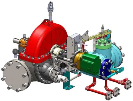
The steam turbine is a fundamental component of a Combined Cycle CHP plant, converting thermal energy from high-pressure steam into mechanical energy, which is then used to generate electricity. In a combined cycle configuration, steam is produced in the Heat Recovery Steam Generator (HRSG) using the exhaust heat from the gas turbine. This steam is directed into the steam turbine, where it expands over a series of rotor blades, causing the shaft to rotate and drive an electric generator. The steam turbine enables the plant to extract additional energy from the gas turbine exhaust, significantly improving overall efficiency.
Steam turbines in CHP plants can be designed for single or multiple pressure levels, often including high, intermediate, and low-pressure sections. High-pressure steam enters the first section of the turbine, producing substantial mechanical energy, while intermediate and low-pressure steam sections further expand the steam to extract as much energy as possible. In cogeneration applications, some steam can be extracted at intermediate stages to supply process heat or district heating, allowing the plant to provide both electricity and thermal energy simultaneously.
The steam turbine consists of multiple key components, including the rotor, blades, casing, bearings, and control valves. The rotor and blades convert the kinetic energy of the expanding steam into rotational motion, while the casing directs the flow of steam and maintains pressure integrity. Bearings support the rotating shaft, and control valves regulate steam flow and extraction to match operational requirements.
Control and monitoring systems are vital for safe and efficient operation of the steam turbine. Sensors continuously measure parameters such as temperature, pressure, rotational speed, and vibration, while automated systems adjust steam flow, extraction, and turbine speed to maintain optimal performance. Safety interlocks, alarms, and emergency shutdown procedures protect the turbine from overpressure, overspeed, and other abnormal conditions.
Maintenance of the steam turbine is essential to ensure reliable performance and longevity. Regular inspection, cleaning, and servicing of blades, bearings, seals, and control components prevent wear, corrosion, and mechanical failure. Predictive maintenance techniques, including vibration analysis and thermal imaging, can help detect potential problems before they affect performance, reducing unplanned downtime and extending operational life.
In summary, the steam turbine is a critical element of a Combined Cycle CHP plant, converting steam energy from the HRSG into electricity while allowing for the extraction of thermal energy for heating applications. Its design, precise control, and proper maintenance are crucial for maximizing efficiency, reliability, and the overall performance of the combined cycle cogeneration system.
The steam turbine in a Combined Cycle CHP plant plays a central role in converting thermal energy from high-pressure steam into mechanical energy, which is then transformed into electricity. Steam produced in the Heat Recovery Steam Generator (HRSG) from the exhaust of the gas turbine is directed into the steam turbine, where it expands through multiple sets of rotor blades. This expansion causes the turbine shaft to rotate, driving an electric generator and producing additional electricity from energy that would otherwise be lost as waste heat. By capturing this energy, the steam turbine significantly increases the overall efficiency of the plant.
Steam turbines in CHP applications are often designed with multiple pressure levels, including high, intermediate, and low-pressure sections. High-pressure steam enters the first stage of the turbine to produce the greatest mechanical energy, while intermediate and low-pressure stages further expand the steam to extract additional energy. In cogeneration mode, steam can also be extracted at intermediate stages to supply process heat or district heating, enabling the plant to provide both electricity and thermal energy simultaneously. This flexibility is essential for balancing electricity and heat output according to demand.
The main components of a steam turbine include the rotor, blades, casing, bearings, and control valves. The rotor and blades convert the kinetic energy of the expanding steam into rotational motion, the casing channels and maintains the flow of steam, and the bearings support the turbine shaft. Control valves regulate steam flow and extraction, ensuring the turbine operates efficiently and safely under varying load conditions.
Control and monitoring systems are vital for the safe operation and efficiency of the steam turbine. Sensors continuously measure steam temperature, pressure, rotational speed, and vibration, while automated controls adjust steam flow, extraction, and turbine speed to optimize performance. Safety interlocks, alarms, and emergency shutdown mechanisms protect the turbine from overpressure, overspeed, and other abnormal conditions, maintaining operational integrity.
Maintenance is critical to ensure the reliable performance and longevity of the steam turbine. Routine inspection, cleaning, and servicing of blades, bearings, seals, and control components prevent wear, corrosion, and mechanical failure. Predictive maintenance tools, such as vibration analysis and thermal imaging, help detect potential issues before they affect performance, minimizing unplanned downtime and extending the turbine’s operational life.
In summary, the steam turbine is an essential component of Combined Cycle CHP plants, converting HRSG-generated steam into electricity while allowing for steam extraction to provide thermal energy. Its design, integration, precise control, and proper maintenance are key to achieving high efficiency, reliability, and flexible energy production in cogeneration applications.
The steam turbine in a Combined Cycle CHP plant is essential for transforming thermal energy from high-pressure steam into mechanical energy, which is then converted into electricity. Steam is produced in the Heat Recovery Steam Generator (HRSG) using the exhaust heat from the gas turbine, and this steam is directed into the turbine where it expands through successive stages of rotor blades. As the steam expands, it drives the turbine shaft, producing mechanical rotation that powers an electric generator. This process allows the plant to extract additional energy from the gas turbine exhaust, significantly increasing overall efficiency.
In CHP applications, steam turbines often feature multiple pressure levels, such as high, intermediate, and low-pressure stages. High-pressure steam enters the first stage to generate maximum mechanical energy, while the intermediate and low-pressure stages extract further energy from the steam. Additionally, some steam can be extracted at intermediate stages to provide process heat or district heating. This ability to supply both electricity and thermal energy simultaneously makes the steam turbine a key component for balancing plant output according to demand.
The steam turbine consists of several critical components, including the rotor, blades, casing, bearings, and control valves. The rotor and blades convert the kinetic energy of expanding steam into mechanical rotation, while the casing directs the steam flow and maintains pressure integrity. Bearings support the rotating shaft, and control valves regulate steam flow and extraction, allowing the turbine to operate efficiently and safely under varying load conditions.
Control and monitoring systems are crucial to maintaining the turbine’s performance and safety. Sensors measure steam temperature, pressure, rotational speed, and vibration, while automated controls adjust steam flow, extraction rates, and turbine speed to optimize efficiency. Safety mechanisms, including alarms, interlocks, and emergency shutdown procedures, protect the turbine from overpressure, overspeed, or other abnormal operating conditions, ensuring reliable operation.
Maintenance is essential to preserve the performance and longevity of the steam turbine. Routine inspection and servicing of blades, bearings, seals, and control components prevent wear, corrosion, and mechanical failure. Predictive maintenance techniques, such as vibration analysis and thermal imaging, can identify potential issues before they affect performance, reducing unplanned downtime and extending operational life.
Overall, the steam turbine is a vital component of Combined Cycle CHP plants, converting HRSG-generated steam into electricity while enabling the extraction of thermal energy for heating applications. Its efficient design, integration with the HRSG, precise control, and proper maintenance are key to maximizing energy efficiency, reliability, and flexible operation in cogeneration systems.
The steam turbine in a Combined Cycle CHP plant is a key component that converts thermal energy from high-pressure steam into mechanical energy, which is subsequently transformed into electricity. Steam generated in the Heat Recovery Steam Generator (HRSG) using the exhaust heat from the gas turbine enters the turbine and expands across multiple sets of blades. This expansion rotates the turbine shaft, driving a connected generator to produce electricity. By utilizing steam that would otherwise go to waste, the steam turbine significantly enhances the overall efficiency of the plant.
Steam turbines in CHP applications are typically designed with multiple pressure levels, including high, intermediate, and low-pressure stages. High-pressure steam enters the first stage, delivering maximum mechanical energy, while intermediate and low-pressure stages further extract energy from the steam before it is condensed. In cogeneration mode, steam can be extracted at intermediate stages to provide process heat or district heating, allowing the plant to simultaneously meet electricity and heat demands efficiently. This flexibility is essential for optimizing fuel use and adjusting output to changing operational needs.
The main components of a steam turbine include the rotor, blades, casing, bearings, and control valves. The rotor and blades convert the energy of expanding steam into rotational motion, the casing directs the flow of steam and maintains pressure integrity, and bearings support the shaft during high-speed rotation. Control valves regulate steam flow and extraction, enabling the turbine to operate efficiently and safely under varying loads.
Control and monitoring systems are critical for safe and efficient turbine operation. Sensors continuously track parameters such as steam pressure, temperature, rotational speed, and vibration, while automated systems adjust steam flow, extraction rates, and turbine speed to maintain optimal performance. Safety mechanisms, including interlocks, alarms, and emergency shutdown procedures, protect the turbine from overpressure, overspeed, or abnormal operating conditions, ensuring reliable and secure operation.
Maintenance is essential to sustain performance and prolong the turbine’s operational life. Regular inspection, cleaning, and servicing of blades, bearings, seals, and control components prevent wear, corrosion, or mechanical failure. Predictive maintenance practices, including vibration analysis and thermal imaging, can detect potential issues before they impact performance, minimizing unplanned downtime and supporting continuous operation.
Overall, the steam turbine is a fundamental part of Combined Cycle CHP plants, transforming HRSG-generated steam into electricity while enabling the extraction of heat for cogeneration purposes. Its design, integration with the HRSG, precise control, and ongoing maintenance are crucial for achieving high efficiency, reliability, and flexibility in electricity and heat production.
Electric Generators
Electric generators are a crucial component of a Combined Cycle CHP plant, converting the mechanical energy produced by both the gas turbine and the steam turbine into electrical energy. In the gas turbine section, the rotating turbine shaft drives a generator that produces electricity directly from the mechanical motion. Similarly, in the steam turbine section, the high-pressure steam drives the turbine rotor, which in turn rotates the connected generator to produce additional electricity. By integrating generators with both turbines, the plant maximizes electricity output while also making efficient use of fuel through heat recovery.
Generators in Combined Cycle CHP plants are typically synchronous machines designed for high efficiency, reliability, and the ability to handle variable loads. They are connected to the turbines via a high-strength shaft and often include cooling systems, such as hydrogen or water cooling, to manage the heat generated during operation. The generators are designed to maintain stable voltage and frequency under varying operational conditions, ensuring that electricity supplied to the grid or on-site facilities meets quality and reliability standards.
Control and monitoring systems are essential for generator operation. Sensors continuously measure electrical parameters such as voltage, current, frequency, and power output. Automated controls regulate excitation, load distribution, and synchronization with the electrical grid. Protection systems, including circuit breakers, relays, and alarms, safeguard the generators from overcurrent, short circuits, overheating, and other abnormal conditions, maintaining safe and reliable operation.
Maintenance of electric generators is critical for continuous performance. Routine inspections, lubrication, cleaning, and testing of components such as bearings, windings, insulation, and cooling systems prevent wear, overheating, and electrical faults. Predictive maintenance techniques, including vibration analysis and thermal imaging, help detect potential problems before they impact operation, minimizing downtime and extending generator life.
In a Combined Cycle CHP plant, electric generators are vital for converting the mechanical energy of both gas and steam turbines into electricity efficiently and reliably. Their robust design, precise control, and proper maintenance ensure continuous power production, supporting the plant’s overall performance and its ability to provide both electricity and heat to meet industrial or district energy demands.
Electric generators are essential components in a Combined Cycle CHP plant, responsible for converting the mechanical energy produced by both the gas turbine and the steam turbine into electrical energy. In the gas turbine section, the rotating shaft directly drives a generator, producing electricity from the mechanical motion. In the steam turbine section, high-pressure steam drives the turbine rotor, which rotates a connected generator to produce additional electricity. By coupling generators to both turbines, the plant maximizes electricity output while efficiently utilizing fuel through waste heat recovery.
These generators are usually synchronous machines designed for high reliability, efficiency, and the ability to handle varying loads. They are mechanically coupled to the turbine shafts and often incorporate advanced cooling systems, such as hydrogen or water cooling, to dissipate the heat generated during operation. Generators are engineered to maintain stable voltage and frequency, ensuring the electricity delivered to the grid or on-site facilities meets quality and reliability standards.
Control and monitoring systems play a vital role in generator operation. Sensors continuously measure voltage, current, frequency, and power output, while automated controls regulate excitation, load sharing, and synchronization with the electrical grid. Protection systems, including circuit breakers, relays, and alarms, safeguard the generators from overcurrent, short circuits, overheating, and other abnormal conditions, ensuring safe and continuous operation.
Maintenance is critical to sustaining generator performance and longevity. Regular inspections, cleaning, lubrication, and testing of components such as bearings, windings, insulation, and cooling systems help prevent mechanical and electrical faults. Predictive maintenance techniques, including vibration analysis and thermal imaging, detect potential issues before they impact performance, reducing unplanned downtime and extending the operational life of the generators.
In Combined Cycle CHP plants, electric generators are fundamental for transforming mechanical energy from both turbines into reliable electricity. Their robust design, integration with turbine systems, precise control, and proper maintenance ensure continuous power production, supporting the overall efficiency and operational flexibility of the plant while enabling simultaneous generation of electricity and heat.
Electric generators in a Combined Cycle CHP plant are critical for converting the mechanical energy produced by both the gas turbine and the steam turbine into usable electricity. The mechanical rotation of the gas turbine shaft drives a generator to produce electricity directly, while the steam turbine converts high-pressure steam from the Heat Recovery Steam Generator (HRSG) into rotational energy that is also transformed into electrical power by a connected generator. By coupling generators to both turbines, the plant is able to maximize electricity output while efficiently utilizing the energy recovered from waste heat.
These generators are typically synchronous machines designed to provide high efficiency, stable voltage, and reliable operation under varying load conditions. They are connected to the turbine shafts and often incorporate advanced cooling systems such as hydrogen or water cooling to manage the heat generated during continuous operation. Proper generator design ensures consistent electrical output and compatibility with the grid or on-site power distribution systems, maintaining the quality and stability of supplied electricity.
Control and monitoring systems are essential for safe and efficient generator operation. Electrical parameters including voltage, current, frequency, and power output are continuously monitored, and automated systems adjust excitation, load sharing, and synchronization with the grid as needed. Safety mechanisms such as circuit breakers, relays, and alarms protect the generators from overcurrent, short circuits, overheating, and other abnormal conditions, ensuring uninterrupted and secure operation.
Regular maintenance is vital to sustain the performance and longevity of generators. This includes inspections, cleaning, lubrication, and testing of critical components such as bearings, windings, insulation, and cooling systems. Predictive maintenance methods, including vibration monitoring and thermal imaging, help detect potential problems before they affect operation, reducing downtime and extending the lifespan of the equipment.
In summary, electric generators are fundamental to the operation of Combined Cycle CHP plants, converting mechanical energy from gas and steam turbines into reliable electricity. Their robust construction, precise control, and proper maintenance ensure continuous electricity production, supporting the plant’s overall efficiency while enabling the simultaneous generation of heat and power for industrial, commercial, and district energy applications.
Electric generators in a Combined Cycle CHP plant play a crucial role in converting mechanical energy from both the gas turbine and the steam turbine into electrical energy. As the gas turbine rotates, its shaft drives a generator, producing electricity directly from the mechanical motion. Similarly, high-pressure steam generated in the Heat Recovery Steam Generator (HRSG) powers the steam turbine, which rotates its connected generator to produce additional electricity. By utilizing generators for both turbines, the plant maximizes electricity output while efficiently capturing and converting energy from waste heat.
These generators are usually synchronous machines engineered for high efficiency, reliable operation, and the ability to handle fluctuating loads. They are coupled directly to the turbine shafts and are often equipped with cooling systems, such as hydrogen or water cooling, to dissipate heat generated during continuous operation. Proper design and cooling ensure that generators maintain stable voltage and frequency, delivering electricity that meets grid requirements or the needs of on-site facilities.
Control and monitoring systems are vital for ensuring safe and efficient generator performance. Sensors continuously track parameters such as voltage, current, frequency, and power output, while automated systems adjust excitation, load sharing, and synchronization with the grid. Protection mechanisms, including circuit breakers, relays, and alarms, prevent damage from overcurrent, overheating, short circuits, or other abnormal conditions, ensuring the generators operate reliably under all conditions.
Maintenance is essential for sustaining generator efficiency and longevity. Routine inspections, lubrication, cleaning, and testing of key components—such as windings, bearings, insulation, and cooling systems—prevent wear and potential failure. Predictive maintenance practices, including vibration analysis and thermal imaging, help detect issues before they escalate, reducing downtime and extending the operational life of the generators.
Overall, electric generators are fundamental to Combined Cycle CHP plants, converting mechanical energy from gas and steam turbines into reliable electricity. Their integration, robust construction, precise control, and consistent maintenance ensure continuous electricity production, supporting both the plant’s efficiency and its ability to deliver simultaneous electricity and heat for industrial or district energy applications.
Condensers and Feedwater System
In a Combined Cycle CHP plant, the condensers and feedwater system play a crucial role in the steam cycle, enabling efficient energy conversion and continuous operation. After the steam passes through the steam turbine, it enters the condenser, where it is cooled and condensed back into water. This process not only recovers latent heat but also creates a vacuum that improves the efficiency of the steam turbine by allowing the exhaust steam to expand more completely. Condensers are typically designed as surface or water-cooled units, using cooling water or other heat transfer media to remove the heat from the steam effectively.
The feedwater system collects the condensed water and pumps it back to the Heat Recovery Steam Generator (HRSG) to be reheated and converted into high-pressure steam again. This closed-loop cycle ensures minimal water loss and maximizes the utilization of thermal energy throughout the plant. The feedwater system includes pumps, valves, piping, and sometimes preheaters, which raise the water temperature before it enters the HRSG, enhancing overall thermal efficiency.
Control and monitoring systems are essential for both the condenser and feedwater system to maintain safe and efficient operation. Sensors track water levels, temperature, pressure, and flow rates, while automated controls regulate pump operation, valve positions, and water flow to ensure a stable and continuous supply of feedwater to the HRSG. Safety mechanisms protect against overpressure, overheating, or low water levels, preventing damage to equipment and maintaining reliable plant operation.
Maintenance of condensers and feedwater systems is critical to sustaining performance. Condenser surfaces and tubes must be regularly cleaned to prevent fouling, scaling, and corrosion, which can reduce heat transfer efficiency. Pumps, valves, and instrumentation require routine inspection and servicing to avoid mechanical failure and ensure continuous operation. Predictive maintenance techniques, such as vibration analysis and thermal monitoring, help identify potential issues early, minimizing downtime and supporting long-term reliability.
In summary, condensers and the feedwater system are vital components in a Combined Cycle CHP plant, recovering steam after turbine expansion, converting it back into water, and delivering it efficiently to the HRSG. Their proper design, integration, control, and maintenance are essential for optimizing thermal efficiency, sustaining continuous operation, and supporting both electricity generation and heat production in cogeneration applications.
In a Combined Cycle CHP plant, condensers and the feedwater system are essential for completing the steam cycle and ensuring efficient energy utilization. After steam passes through the steam turbine, it enters the condenser, where it is cooled and condensed back into water. This condensation process not only recovers the latent heat of the steam but also creates a vacuum that enhances the efficiency of the steam turbine by allowing the exhaust steam to expand more fully. Condensers are typically designed as surface condensers or water-cooled units, using cooling water or other heat transfer media to remove heat from the exhaust steam effectively.
The feedwater system collects the condensed water from the condenser and pumps it back to the Heat Recovery Steam Generator (HRSG) for reheating and conversion into high-pressure steam. This closed-loop process ensures minimal water loss while maximizing the utilization of thermal energy throughout the plant. The system includes pumps, valves, piping, and sometimes preheaters, which raise the water temperature before it enters the HRSG, further improving overall thermal efficiency and reducing the energy required for steam generation.
Control and monitoring of the condenser and feedwater system are vital for reliable and efficient operation. Sensors monitor water levels, flow rates, pressure, and temperature, while automated controls regulate pump operation, valve positions, and water flow to maintain a steady feedwater supply to the HRSG. Safety features protect against overpressure, overheating, or low water conditions, preventing damage to equipment and ensuring continuous and stable plant operation.
Maintenance is crucial for sustaining the performance of condensers and feedwater systems. Condenser tubes and surfaces must be regularly cleaned to prevent fouling, scaling, and corrosion, which can reduce heat transfer efficiency. Pumps, valves, and instrumentation require routine inspection and servicing to avoid mechanical failures. Predictive maintenance tools, such as vibration analysis and thermal imaging, help detect potential issues before they affect performance, minimizing downtime and extending equipment life.
Overall, condensers and the feedwater system are critical to the operation of Combined Cycle CHP plants, enabling the recovery of steam after turbine expansion, returning it to the HRSG as water, and maintaining a continuous, efficient steam cycle. Proper design, integration, control, and maintenance of these systems are essential for optimizing plant efficiency, reliability, and the simultaneous production of electricity and heat.
In a Combined Cycle CHP plant, condensers and the feedwater system are essential for maintaining the efficiency and continuity of the steam cycle. After the steam has passed through the steam turbine, it enters the condenser, where it is cooled and transformed back into liquid water. This condensation not only recovers the latent heat from the steam but also creates a vacuum that allows the steam turbine to expand more effectively, improving overall turbine efficiency. Condensers are typically water-cooled or surface-type units, designed to transfer heat from the steam to the cooling medium efficiently.
The feedwater system plays a critical role by collecting the condensed water and returning it to the Heat Recovery Steam Generator (HRSG) to be reheated into high-pressure steam. This closed-loop system minimizes water loss and maximizes energy utilization across the plant. Feedwater pumps, valves, piping, and sometimes preheaters are included in the system to ensure a steady supply of water at the proper temperature and pressure, enhancing the efficiency of steam generation in the HRSG.
Control and monitoring are vital for both condensers and feedwater systems. Sensors track water levels, temperatures, pressures, and flow rates, while automated control systems regulate pump operation, valve positions, and feedwater flow to maintain consistent operation. Safety features, such as pressure relief valves and alarms, protect the system from overpressure, overheating, or low-water conditions, ensuring reliable and safe plant performance.
Maintenance is critical to sustain the performance and longevity of condensers and feedwater systems. Condenser tubes and heat transfer surfaces must be regularly cleaned to prevent fouling, scaling, and corrosion, which can impair heat transfer and reduce efficiency. Pumps, valves, and instrumentation require routine inspection and servicing to avoid mechanical failures. Predictive maintenance techniques, such as vibration analysis and thermal imaging, can detect issues before they impact operation, minimizing unplanned downtime.
Overall, condensers and the feedwater system are fundamental components in a Combined Cycle CHP plant, completing the steam cycle by converting turbine exhaust back into water and delivering it to the HRSG. Their proper design, integration, control, and maintenance are crucial for maintaining plant efficiency, ensuring continuous operation, and supporting the simultaneous generation of electricity and thermal energy.
In a Combined Cycle CHP plant, condensers and the feedwater system are key elements for maintaining the efficiency and continuity of the steam cycle. After steam exits the steam turbine, it enters the condenser, where it is cooled and converted back into liquid water. This process not only recovers the latent heat of the steam but also creates a vacuum that allows the turbine to expand the remaining steam more effectively, improving overall energy extraction. Condensers are typically water-cooled or surface-type units, designed to transfer heat efficiently from the steam to the cooling medium.
The feedwater system collects the condensed water from the condenser and pumps it back to the Heat Recovery Steam Generator (HRSG) for reheating into high-pressure steam. This closed-loop process minimizes water loss and ensures maximum utilization of thermal energy throughout the plant. Feedwater pumps, valves, piping, and preheaters are often included to maintain the proper water temperature and pressure before it enters the HRSG, which enhances the efficiency of steam generation and reduces energy consumption.
Proper control and monitoring of the condensers and feedwater system are essential for reliable operation. Sensors continuously measure water levels, pressure, temperature, and flow rates, while automated systems regulate pump operation, valve positions, and feedwater flow to ensure steady operation. Safety devices protect the system from overpressure, overheating, or low water conditions, safeguarding equipment and maintaining stable plant performance.
Maintenance is critical to preserve the performance and longevity of condensers and feedwater systems. Condenser surfaces and tubes must be cleaned regularly to prevent fouling, scaling, or corrosion that could reduce heat transfer efficiency. Pumps, valves, and instrumentation require routine inspection and servicing to avoid mechanical failure. Predictive maintenance techniques, such as vibration analysis and thermal imaging, can detect potential problems early, minimizing downtime and supporting continuous operation.
Overall, condensers and the feedwater system are fundamental to the operation of Combined Cycle CHP plants, converting turbine exhaust steam back into water and delivering it to the HRSG for reuse. Their proper design, integration, control, and maintenance are essential for optimizing efficiency, sustaining continuous operation, and supporting the plant’s dual objectives of electricity generation and heat production.
Control and Monitoring Systems
Control and monitoring systems are a critical component of Combined Cycle CHP plants, ensuring safe, efficient, and reliable operation of all plant processes. These systems continuously monitor the performance of turbines, generators, HRSGs, condensers, feedwater systems, and auxiliary equipment, collecting data on parameters such as temperature, pressure, flow rates, rotational speed, and electrical output. By analyzing this data in real time, operators and automated control systems can maintain optimal conditions, adjust operations to match demand, and prevent equipment stress or failures.
Advanced control systems use programmable logic controllers (PLCs), distributed control systems (DCS), and supervisory control and data acquisition (SCADA) platforms to integrate all plant components. These systems regulate fuel supply, steam generation, turbine speed, generator load, feedwater flow, and heat extraction, ensuring that both electricity and heat production are balanced according to operational priorities. By maintaining precise control, these systems enhance efficiency, reduce fuel consumption, and minimize emissions.
Monitoring systems also play a vital role in safety. Sensors detect abnormal conditions such as overpressure, overheating, vibrations, or deviations in electrical parameters. Automated alarms and interlocks trigger corrective actions or initiate shutdown procedures to protect equipment and personnel. Data logging and trend analysis allow operators to identify potential issues before they escalate, enabling predictive maintenance and reducing the risk of unplanned downtime.
Regular calibration, testing, and maintenance of control and monitoring systems are essential to ensure accurate readings and reliable operation. Software updates, sensor replacement, and system diagnostics help maintain the integrity of the monitoring network. In addition, operator training ensures that personnel can interpret data correctly, respond to alarms promptly, and optimize plant performance under varying operating conditions.
In summary, control and monitoring systems are the backbone of Combined Cycle CHP plant operations, enabling precise regulation, continuous performance monitoring, and safe operation of all plant components. Their proper design, integration, and maintenance are essential for maximizing efficiency, maintaining reliability, and supporting the simultaneous production of electricity and heat.
Control and monitoring systems are essential for the reliable and efficient operation of a Combined Cycle CHP plant. These systems continuously track the performance of critical components, including gas and steam turbines, generators, HRSGs, condensers, feedwater systems, and auxiliary equipment. Parameters such as temperature, pressure, flow rates, rotational speeds, and electrical output are measured in real time, allowing operators and automated control systems to maintain optimal conditions, adjust processes according to demand, and prevent stress or damage to equipment.
Advanced control systems often incorporate programmable logic controllers (PLCs), distributed control systems (DCS), and supervisory control and data acquisition (SCADA) platforms, which integrate all plant components into a centralized monitoring network. These systems regulate fuel supply, steam generation, turbine operation, generator load, feedwater flow, and heat extraction, ensuring that electricity and heat production are balanced efficiently. By maintaining precise control over each process, these systems enhance plant efficiency, reduce fuel consumption, and minimize emissions.
Safety is a major function of control and monitoring systems. Sensors detect abnormal operating conditions such as overpressure, overheating, excessive vibration, or deviations in electrical parameters. When an anomaly is detected, alarms are triggered and automated interlocks can initiate corrective actions or even a safe shutdown to protect equipment and personnel. The continuous collection of operational data also allows trend analysis and predictive maintenance, enabling operators to identify potential problems before they cause failures or unplanned downtime.
Maintenance of control and monitoring systems is vital to ensure accuracy and reliability. Regular calibration, testing, software updates, and sensor replacement help maintain the integrity of the monitoring network. Proper maintenance ensures that all readings are accurate, control responses are timely, and potential issues are addressed promptly. Operator training is also critical, allowing personnel to interpret data correctly, respond to alarms effectively, and optimize plant performance under variable conditions.
Overall, control and monitoring systems form the backbone of a Combined Cycle CHP plant, ensuring that all components operate safely, efficiently, and in coordination. Their proper design, integration, and maintenance are essential for maximizing operational performance, supporting the simultaneous generation of electricity and heat, and maintaining long-term reliability of the plant.
Control and monitoring systems are vital for ensuring the efficient, safe, and reliable operation of a Combined Cycle CHP plant. They continuously observe and regulate the performance of critical equipment, including gas and steam turbines, electric generators, HRSGs, condensers, feedwater systems, and auxiliary systems. Real-time measurements of parameters such as temperature, pressure, flow rates, rotational speed, and electrical output allow operators and automated systems to maintain optimal operating conditions, adjust processes based on demand, and prevent excessive wear or equipment failure.
Modern control systems typically integrate programmable logic controllers (PLCs), distributed control systems (DCS), and supervisory control and data acquisition (SCADA) platforms to create a centralized monitoring and control environment. These systems manage fuel injection, steam generation, turbine speed, generator load, feedwater supply, and heat extraction, ensuring that electricity and thermal energy are produced efficiently and in balance with operational needs. Precise control reduces fuel consumption, increases plant efficiency, and minimizes emissions, contributing to sustainable energy generation.
Safety is a critical aspect of control and monitoring systems. Sensors detect abnormal conditions, such as overpressure, overheating, unusual vibrations, or deviations in electrical output, and trigger alarms or automated corrective actions. Interlocks and emergency shutdown protocols protect equipment and personnel from damage, while continuous data logging allows trend analysis and predictive maintenance. By identifying potential issues early, operators can schedule maintenance before problems escalate, reducing unplanned downtime and prolonging the life of plant components.
Maintenance of control and monitoring systems is essential for accuracy and reliability. Routine calibration, inspection, software updates, and sensor replacement ensure that measurements are precise and controls respond appropriately. Training operators to interpret data and respond correctly to system alerts is equally important, allowing the plant to operate safely and efficiently under varying load conditions.
In summary, control and monitoring systems are the backbone of a Combined Cycle CHP plant, providing real-time oversight, precise regulation, and safety management for all major components. Their proper design, integration, and maintenance are crucial for achieving optimal plant efficiency, reliable electricity and heat production, and long-term operational stability.
Control and monitoring systems are fundamental to the operation of a Combined Cycle CHP plant, providing continuous oversight and regulation of all critical components. These systems track the performance of gas and steam turbines, electric generators, HRSGs, condensers, feedwater systems, and auxiliary equipment, measuring parameters such as temperature, pressure, flow rates, rotational speed, and electrical output in real time. This continuous monitoring allows operators and automated systems to maintain optimal conditions, adjust processes to meet changing energy demands, and prevent stress or damage to equipment.
Advanced control systems integrate technologies such as programmable logic controllers (PLCs), distributed control systems (DCS), and supervisory control and data acquisition (SCADA) platforms to centralize monitoring and operational control. They regulate fuel supply, steam generation, turbine operation, generator load, feedwater flow, and heat extraction to ensure that electricity and heat production are balanced efficiently. By providing precise control, these systems improve plant efficiency, reduce fuel consumption, and minimize emissions while supporting flexible operation under variable load conditions.
Safety functions are an integral part of control and monitoring systems. Sensors detect abnormal operating conditions such as overpressure, overheating, unusual vibration, or deviations in electrical parameters. Alarms, interlocks, and automated shutdown procedures protect both personnel and equipment from potential damage. Additionally, data logging and trend analysis allow operators to identify potential issues early, facilitating predictive maintenance and minimizing unplanned downtime.
Maintenance of control and monitoring systems is crucial to preserve their accuracy and reliability. Regular calibration, inspections, software updates, and sensor replacement ensure that measurements are precise and controls respond correctly. Operator training is also essential to enable proper interpretation of data, quick response to alarms, and optimization of plant performance under various operating conditions.
Overall, control and monitoring systems form the backbone of Combined Cycle CHP plants, enabling real-time oversight, precise regulation, and safe operation of all major components. Their proper design, integration, and maintenance are essential for achieving high efficiency, reliable electricity and heat production, and long-term operational stability.
Auxiliary Systems
Auxiliary systems are essential supporting components in a Combined Cycle CHP plant, ensuring the reliable and efficient operation of the main power generation equipment. These systems provide the necessary services and infrastructure for turbines, generators, HRSGs, condensers, feedwater systems, and control units to operate effectively. They include systems for lubrication, cooling, fuel supply, compressed air, water treatment, fire protection, and electrical distribution, all of which contribute to the smooth and continuous functioning of the plant.
Lubrication systems are critical for turbines, generators, pumps, and other rotating equipment. They supply oil at controlled pressure and temperature to bearings and moving parts, reducing friction, wear, and the risk of mechanical failure. Cooling systems, including water, air, or hydrogen cooling, remove heat from generators, bearings, and other equipment, maintaining optimal operating temperatures and preventing overheating. Fuel supply systems ensure that gas or other fuels are delivered at the correct pressure, quality, and flow rate for efficient combustion in the gas turbine, while redundant fuel control systems provide safety and operational reliability.
Compressed air systems support instrumentation, pneumatic controls, valve actuation, and other automated functions throughout the plant. Water treatment systems condition boiler feedwater, cooling water, and condensate to prevent scaling, corrosion, and fouling, which could reduce efficiency or damage equipment. Fire protection systems, including detectors, alarms, and suppression systems, safeguard the plant from fire hazards. Electrical auxiliary systems provide power to pumps, fans, control systems, lighting, and emergency equipment, ensuring uninterrupted operation even under abnormal conditions.
Control and monitoring of auxiliary systems are essential for their efficient operation. Sensors and automation regulate pressures, flows, temperatures, and operational status, while alarms and interlocks protect against faults and failures. Regular maintenance, inspection, and testing of pumps, compressors, lubrication lines, water treatment units, and electrical equipment are crucial to avoid unexpected breakdowns and ensure long-term reliability. Predictive maintenance tools, such as vibration analysis, thermal imaging, and fluid analysis, are often employed to detect early signs of wear or malfunction.
In summary, auxiliary systems form the backbone of support for a Combined Cycle CHP plant, enabling the main equipment to operate efficiently, safely, and reliably. Their proper design, integration, control, and maintenance are essential for ensuring continuous electricity and heat production, protecting plant assets, and maintaining overall operational stability.
Auxiliary systems are essential components in a Combined Cycle CHP plant, providing the support required for the main power generation equipment to operate efficiently and reliably. These systems ensure that turbines, generators, HRSGs, condensers, feedwater systems, and control units receive the necessary services to maintain continuous operation. Key auxiliary systems include lubrication, cooling, fuel supply, compressed air, water treatment, fire protection, and electrical distribution, all of which contribute to the smooth functioning of the plant.
Lubrication systems supply oil at controlled pressure and temperature to bearings and moving parts in turbines, generators, and pumps, reducing friction, wear, and the risk of mechanical failure. Cooling systems, whether water, air, or hydrogen-based, remove excess heat from generators, bearings, and other critical equipment, maintaining optimal operating temperatures and preventing overheating. Fuel supply systems ensure that natural gas or other fuels are delivered at the correct pressure, quality, and flow rate to the gas turbine for efficient combustion, while redundant control systems provide additional safety and operational reliability.
Compressed air systems support instrumentation, pneumatic controls, and valve actuation throughout the plant, enabling precise automation of processes. Water treatment systems condition boiler feedwater, cooling water, and condensate, preventing scaling, corrosion, and fouling that could reduce efficiency or damage equipment. Fire protection systems, including detection, alarm, and suppression systems, safeguard personnel and plant assets from fire hazards. Electrical auxiliary systems provide power to pumps, fans, control systems, lighting, and emergency equipment, ensuring uninterrupted operation even under abnormal conditions.
Control and monitoring of auxiliary systems are critical for efficient and safe operation. Sensors continuously measure pressure, temperature, flow, and operational status, while automated systems regulate and optimize the functioning of pumps, compressors, valves, and treatment units. Alarms and interlocks protect equipment from faults, and regular maintenance ensures that all auxiliary components remain reliable. Predictive maintenance techniques, including vibration analysis, thermal imaging, and fluid monitoring, help detect potential issues early, reducing the likelihood of unplanned downtime.
Overall, auxiliary systems form the foundation that supports all major equipment in a Combined Cycle CHP plant. Their proper design, integration, control, and maintenance are crucial for sustaining continuous electricity and heat production, protecting plant equipment, and ensuring overall operational efficiency and reliability.
Auxiliary systems are vital for the continuous and efficient operation of a Combined Cycle CHP plant, providing essential support to the main power generation equipment. These systems ensure that turbines, generators, HRSGs, condensers, feedwater systems, and control units function reliably under all operating conditions. They include lubrication, cooling, fuel supply, compressed air, water treatment, fire protection, and electrical distribution systems, each contributing to the smooth and safe operation of the plant.
Lubrication systems deliver oil at controlled pressure and temperature to bearings and moving parts in turbines, generators, and pumps, minimizing friction, wear, and the risk of mechanical failure. Cooling systems, including water, air, or hydrogen-based cooling, remove excess heat from generators, bearings, and other critical components, maintaining optimal operating temperatures and preventing overheating. Fuel supply systems ensure a steady delivery of natural gas or other fuels at the correct pressure, quality, and flow rate for efficient combustion in the gas turbine, while redundancy in fuel control adds an extra layer of safety and reliability.
Compressed air systems provide the necessary pressure for instrumentation, pneumatic controls, and valve actuation, allowing precise automation and smooth operation of plant processes. Water treatment systems condition boiler feedwater, cooling water, and condensate to prevent scaling, corrosion, and fouling, which could impair efficiency or damage equipment. Fire protection systems, including detection, alarm, and suppression units, safeguard both personnel and plant assets. Electrical auxiliary systems supply power to pumps, fans, control devices, lighting, and emergency equipment, ensuring continuous operation even under abnormal conditions.
Control and monitoring of auxiliary systems are critical to maintaining plant efficiency and safety. Sensors track key parameters such as temperature, pressure, flow, and operational status, while automated controls adjust pumps, compressors, valves, and treatment units to optimize performance. Alarms and interlocks protect equipment from faults and failures, while data collection and analysis enable predictive maintenance, helping to detect potential issues before they result in unplanned downtime.
In summary, auxiliary systems form the backbone of support for all major components in a Combined Cycle CHP plant. Their proper design, integration, control, and maintenance are essential to ensure continuous and efficient electricity and heat production, protect plant assets, and maintain overall operational stability and reliability.
Auxiliary systems are critical to the operation of a Combined Cycle CHP plant, providing the support necessary for the main generation equipment to function efficiently and reliably. They ensure that gas and steam turbines, generators, HRSGs, condensers, feedwater systems, and control units have the resources needed to maintain continuous operation. These systems include lubrication, cooling, fuel supply, compressed air, water treatment, fire protection, and electrical distribution, all of which are essential for smooth and safe plant operation.
Lubrication systems supply oil at controlled pressures and temperatures to bearings and moving parts in turbines, generators, and pumps, reducing friction and wear while preventing mechanical failures. Cooling systems, which may be water, air, or hydrogen-based, remove heat from generators, bearings, and other equipment, maintaining optimal operating temperatures and preventing overheating. Fuel supply systems ensure that natural gas or other fuels are delivered at the proper pressure, quality, and flow rate for efficient combustion in the gas turbine, and redundant fuel controls enhance operational safety and reliability.
Compressed air systems provide the pressure required for pneumatic controls, instrumentation, and valve operation, supporting precise automation and smooth functioning of plant processes. Water treatment systems condition feedwater, cooling water, and condensate to prevent scaling, corrosion, and fouling, which can reduce efficiency or damage equipment. Fire protection systems, including alarms, detectors, and suppression mechanisms, protect the plant and personnel from fire hazards. Electrical auxiliary systems provide power to pumps, fans, control devices, lighting, and emergency equipment, ensuring uninterrupted operation under all conditions.
Control and monitoring of auxiliary systems are vital to ensure efficient and safe performance. Sensors continuously track pressures, temperatures, flow rates, and operational status, while automated systems adjust pumps, compressors, valves, and water treatment units to maintain optimal operation. Alarms and interlocks safeguard equipment from faults, and predictive maintenance using techniques such as vibration analysis, thermal imaging, and fluid monitoring helps detect potential problems before they cause downtime.
Overall, auxiliary systems form the foundation that enables a Combined Cycle CHP plant to operate reliably and efficiently. Their proper design, integration, control, and maintenance are essential for continuous electricity and heat production, protecting critical equipment and maintaining stable, safe, and efficient plant operations.
Microturbine CHP Plants
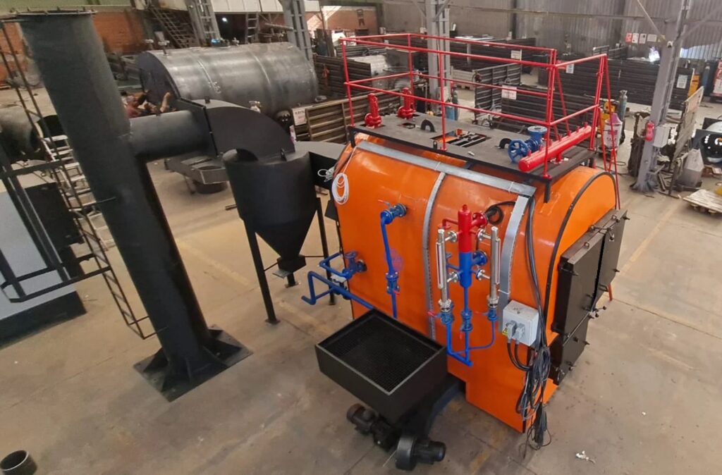
Microturbine CHP plants are compact and highly efficient energy systems designed to generate both electricity and thermal energy for small- to medium-scale applications, such as commercial buildings, hospitals, or industrial facilities. Unlike large gas or steam turbines, microturbines are smaller in size, typically ranging from tens of kilowatts to a few hundred kilowatts in electrical output, making them suitable for distributed generation. They operate on a simple cycle or a recuperated cycle, using natural gas, biogas, or other gaseous fuels to drive the turbine and produce electricity while recovering the waste heat for heating or hot water applications.
The main advantage of microturbine CHP plants is their ability to provide highly reliable and continuous electricity while simultaneously supplying usable heat. The waste heat from the microturbine exhaust can be captured through a heat recovery system, such as a heat exchanger, and utilized for space heating, domestic hot water, or process heat, significantly increasing the overall system efficiency. In many installations, overall energy efficiency can exceed 75–80% by effectively combining electricity generation with heat recovery, making them particularly attractive for applications where both electrical and thermal energy are required.
Microturbine CHP systems consist of a few key components: the turbine itself, a generator, a recuperator or heat recovery unit, a control system, and auxiliary systems. The microturbine includes a compressor, combustor, and turbine in a single compact unit, producing high-speed rotational energy that drives a generator to produce electricity. The recuperator or heat recovery unit captures the thermal energy from the exhaust gases and transfers it to water or air for heating purposes. The control system regulates fuel flow, turbine speed, temperature, and electrical output, ensuring safe and efficient operation under varying loads.
These systems are valued for their modularity, low emissions, and low maintenance requirements compared to larger turbine or boiler systems. Many microturbines operate on lean combustion, reducing NOx and CO emissions, and their compact design allows for installation in limited spaces or near the point of energy consumption, reducing transmission losses. Monitoring and auxiliary systems provide operational oversight, including sensors for temperature, pressure, and flow, as well as alarms and interlocks for safety and predictive maintenance, helping maintain continuous and reliable operation.
Overall, microturbine CHP plants offer a flexible and efficient solution for distributed energy generation, combining on-site electricity production with effective heat recovery. Their small footprint, high efficiency, low emissions, and modular design make them suitable for a wide range of applications, delivering both energy cost savings and environmental benefits while enhancing energy reliability for commercial and industrial users.
Compressor
The compressor is a key component of a microturbine, responsible for drawing in ambient air and compressing it to a higher pressure before it enters the combustion chamber. This pressurized air is essential for achieving efficient combustion and optimal turbine performance. The compressor is typically designed as a centrifugal or axial unit and is integrated directly into the turbine shaft for compactness and simplicity.
Combustion Chamber (Combustor)
The combustion chamber is where the compressed air mixes with fuel, such as natural gas or biogas, and is ignited to produce high-temperature, high-pressure gases. These gases expand rapidly and drive the turbine rotor, generating mechanical energy. The combustor is designed for lean combustion to reduce emissions of NOx and CO while maintaining stable and efficient operation.
Turbine
The turbine converts the energy from the high-pressure, high-temperature combustion gases into mechanical rotational energy. This mechanical energy is used to drive both the generator and, in some designs, the compressor. Microturbines typically operate at very high rotational speeds, which requires precision engineering and advanced materials to withstand thermal and mechanical stresses.
Electric Generator
The electric generator is coupled directly to the turbine shaft and converts the mechanical energy from the turbine into electricity. Most microturbines use high-speed permanent magnet or induction generators capable of producing electrical power with high efficiency and reliability. The generator is designed to provide stable voltage and frequency suitable for on-site use or grid connection.
Recuperator / Heat Recovery Unit
The recuperator or heat recovery unit captures thermal energy from the turbine exhaust gases and transfers it to water, air, or another medium for heating purposes. This recovered heat can be used for space heating, domestic hot water, or industrial processes, significantly increasing the overall energy efficiency of the microturbine CHP system.
Control System
The control system manages the operation of the microturbine, regulating fuel flow, turbine speed, temperature, and electrical output. It ensures safe and efficient performance under varying load conditions and integrates with auxiliary systems for monitoring, safety, and maintenance alerts.
Auxiliary Systems
Auxiliary systems support the microturbine’s operation and include lubrication, cooling, fuel supply, electrical distribution, and monitoring systems. These systems ensure that all components operate reliably, safely, and efficiently, providing continuous electricity and heat production with minimal downtime.
The compressor in a microturbine CHP plant is one of the most important components, as it prepares the air required for efficient combustion and turbine operation. It draws in ambient air and compresses it to a much higher pressure, typically in the range of 3 to 5 bar for microturbines, which is then delivered to the combustion chamber. This pressurized air ensures that the fuel-air mixture burns more completely and at higher temperatures, which improves both efficiency and power output. The design is usually compact and integrated into the same shaft that drives the turbine and generator, which allows the entire unit to remain small and efficient.
Microturbines typically use a centrifugal compressor, as it is well-suited to the high rotational speeds that these systems operate at, often reaching tens of thousands of revolutions per minute. The centrifugal design also allows for simplicity and durability, making it ideal for the low-maintenance requirements that microturbine systems are known for. Since the compressor and turbine share the same shaft, the performance of the compressor directly affects the turbine output, meaning its efficiency is crucial to the entire system’s performance.
The air compression process also plays a vital role in emission control. By delivering the right amount of air at the correct pressure, the compressor helps maintain a lean combustion mixture, which reduces nitrogen oxide (NOx) and carbon monoxide (CO) emissions. This is especially important in microturbine CHP systems, where environmental performance and compliance with emission standards are key advantages.
Another important aspect of the compressor in microturbines is the integration with the recuperator or heat recovery system. In many designs, the compressed air passes through a recuperator before entering the combustor, allowing the air to be preheated by exhaust gases. This increases combustion efficiency, reduces fuel consumption, and further improves the overall energy balance of the system. The compressor’s role in this cycle is essential, as it provides the air at the right pressure to maximize the effectiveness of heat recovery.
Overall, the compressor is not just a support component but a core element that dictates the performance, efficiency, and reliability of a microturbine CHP plant. Its precise design and seamless integration with the turbine, generator, and recuperator ensure that the system delivers high efficiency, low emissions, and long-term durability for continuous combined heat and power production.
The compressor in a microturbine CHP plant is the starting point of the entire energy conversion process, and its performance has a direct influence on how effectively the system operates. By drawing in ambient air and compressing it to a higher pressure, the compressor creates the conditions required for clean and efficient combustion in the next stage of the cycle. Without this pressurization, the fuel-air mixture would burn less efficiently, leading to reduced power output and higher emissions. Because microturbines are designed to be compact and efficient, the compressor is usually mounted on the same shaft as the turbine and generator, forming a highly integrated system where every part depends on the precise operation of the others.
One of the defining characteristics of microturbine compressors is the use of centrifugal designs, which are well suited to the extremely high rotational speeds at which these systems operate. A centrifugal compressor can efficiently handle the airflow required, while maintaining a relatively small and durable design. This choice of technology not only makes the entire unit more compact but also ensures lower maintenance demands, which is a critical factor for microturbine installations in commercial and industrial environments where reliability and low operating costs are priorities.
The work of the compressor also has significant implications for environmental performance. By delivering the correct amount of air at the right pressure, it ensures that combustion occurs with a lean fuel-air mixture. This leads to more complete burning of the fuel, reducing the formation of nitrogen oxides and carbon monoxide, two of the main pollutants associated with combustion systems. The precision with which the compressor operates is therefore directly tied to the plant’s ability to comply with strict emissions regulations and maintain its reputation as a clean energy solution.
Another important role of the compressor in microturbine systems is its connection with the recuperator or heat recovery unit. In many designs, the compressed air is routed through the recuperator before entering the combustion chamber, allowing it to be preheated by the turbine’s exhaust gases. This clever use of waste heat increases the temperature of the incoming air, reducing the amount of additional fuel required for combustion and improving overall system efficiency. The compressor is central to this process, as it supplies the air at the necessary pressure and flow rate to maximize the benefits of heat recovery and support the high efficiency levels that CHP systems are valued for.
In summary, the compressor in a microturbine CHP plant is not simply a preparatory device but an integral part of the system’s performance, efficiency, and environmental footprint. Its ability to deliver consistent and precisely pressurized airflow ensures efficient combustion, enables effective use of heat recovery, supports low emissions, and contributes to the compact, reliable nature of microturbine technology. Without the compressor functioning optimally, the entire cycle would lose its balance, making it one of the most essential elements in the design and operation of microturbine CHP systems.
The compressor in a microturbine CHP plant is often described as the heart of the system, because it initiates the sequence that allows energy conversion to take place. By pulling in ambient air and compressing it to a significantly higher pressure, the compressor makes sure that the combustion chamber receives the right conditions for a stable and efficient burn. This function is not only about increasing pressure but also about ensuring the correct volume of air is supplied consistently, which directly impacts both power generation and the efficiency of heat recovery. Since microturbines are designed for continuous operation in environments such as commercial buildings, hospitals, and industrial facilities, the compressor must be able to deliver a constant flow of high-pressure air with minimal variation or downtime.
The compactness of microturbine systems is closely tied to the design of the compressor. Instead of large, multi-stage compressors found in heavy-duty turbines, microturbines rely on centrifugal compressors that can achieve high rotational speeds within a relatively small footprint. These compressors are mounted on the same shaft as the turbine and generator, making the entire system lighter, more efficient, and easier to maintain. Operating at extremely high speeds requires precise engineering and advanced materials to withstand the mechanical and thermal stresses, which is why the compressor is often among the most technologically advanced parts of the microturbine.
The environmental benefits of microturbine CHP plants also rely heavily on the compressor’s performance. By ensuring an optimal fuel-to-air ratio, the compressor enables lean combustion, which is key to lowering nitrogen oxide and carbon monoxide emissions. This makes microturbines attractive for facilities that must meet strict emissions standards while also reducing their energy costs. A poorly performing compressor, on the other hand, could upset this balance, leading to incomplete combustion, higher emissions, and reduced overall efficiency.
The role of the compressor extends even further when it is integrated with a recuperator in the system design. After being compressed, the air is often routed through a recuperator that preheats it using waste heat from the turbine’s exhaust. This process significantly enhances fuel efficiency, as the preheated air requires less additional energy to reach combustion temperatures. The compressor’s contribution here is indispensable, because the air it delivers must not only be at the right pressure but also in the right condition to maximize the effectiveness of the recuperator. In this way, the compressor acts as the enabler for one of the most critical efficiency-boosting features of microturbine technology.
Reliability and durability are also defining qualities of compressors in microturbine CHP plants. Since these systems are often expected to run continuously with limited maintenance, the compressor must operate efficiently over long intervals without degradation in performance. This is achieved through careful design, precision manufacturing, and the use of advanced materials that resist wear and thermal stress. Ultimately, the compressor determines how smoothly the entire microturbine system operates, making it central to both the energy output and the economic viability of combined heat and power solutions at this scale.
The compressor in a microturbine CHP plant is more than just a mechanical component; it is the element that defines how well the entire system performs. By compressing air before it reaches the combustor, it sets the stage for efficient combustion, which in turn drives the turbine and ultimately generates electricity and usable heat. The quality of compression directly affects flame stability, combustion temperature, and the efficiency of fuel utilization. In a system where every fraction of energy matters, the compressor’s ability to deliver the right amount of air at the right pressure is indispensable for keeping efficiency levels high and emissions low.
Because microturbines operate at extremely high speeds, the compressor must be engineered with precision and balance to withstand the mechanical loads and stresses involved. Centrifugal designs are most common in these applications because they can handle high rotational speeds while keeping the system compact and relatively simple. This compactness is critical in environments where space is limited, such as urban commercial buildings or small-scale industrial sites. By being integrated on the same shaft as the turbine and generator, the compressor also minimizes energy losses, creating a highly efficient arrangement that supports the distributed generation concept behind microturbine CHP technology.
The influence of the compressor extends beyond the combustion process itself. In recuperated microturbine designs, the air leaving the compressor is routed through a recuperator that uses turbine exhaust gases to preheat the compressed air before it enters the combustor. This reduces the amount of additional fuel required, enhancing the overall efficiency of the system. The compressor is central to this cycle because it provides the airflow at the necessary pressure to make heat recovery effective. Without reliable compression, the recuperator cannot function properly, and the efficiency gains that set microturbines apart would be lost.
Environmental performance is another area where the compressor’s role is critical. Lean combustion, which requires precise control of the air-to-fuel ratio, is only possible when the compressor consistently delivers a stable supply of pressurized air. This ensures that the combustion process produces fewer nitrogen oxides and carbon monoxide, making the microturbine a cleaner alternative to many other small-scale generation systems. For facilities concerned about sustainability and regulatory compliance, the compressor’s ability to maintain these operating conditions is a defining advantage.
In the long term, the compressor’s reliability contributes significantly to the economic feasibility of microturbine CHP plants. These systems are often expected to run continuously for thousands of hours per year, sometimes in remote or difficult-to-access locations. A robust and durable compressor design reduces downtime, minimizes maintenance requirements, and extends the service life of the system. In this way, the compressor is not only a functional necessity but also a cornerstone of the economic and environmental benefits that make microturbine CHP plants an attractive solution for modern energy needs.
Combustion Chamber (Combustor)
The combustion chamber in a microturbine CHP plant is the component where the real energy conversion begins, as it is here that the chemical energy stored in the fuel is released and transformed into thermal energy. After the compressor delivers pressurized air, the combustion chamber mixes this air with fuel—most commonly natural gas, biogas, or other clean gaseous fuels—and ignites the mixture to create high-temperature, high-pressure gases. These gases then expand rapidly and are directed toward the turbine, providing the energy that drives the shaft and ultimately produces both electricity and recoverable heat. The combustor’s ability to sustain stable, efficient, and clean combustion is crucial, as it directly impacts the performance, emissions, and reliability of the entire microturbine CHP system.
In microturbines, the design of the combustion chamber emphasizes compactness, durability, and low emissions. Lean-burn combustion technology is often used, meaning that the fuel is mixed with an excess of air to ensure more complete burning of the fuel. This significantly reduces nitrogen oxide (NOx) emissions, which are a major environmental concern in conventional combustion systems. The chamber must be carefully engineered to allow thorough mixing of the air and fuel, ensuring consistent flame stability even under fluctuating loads. This is especially important in CHP applications, where the demand for electricity and heat can vary over time, requiring the combustor to respond quickly while maintaining efficiency.
Another essential feature of the combustor is its ability to handle different types of fuels, depending on the installation. While many systems are optimized for natural gas, microturbines are increasingly used in facilities that produce biogas or landfill gas, making fuel flexibility a valuable asset. The combustor must be designed to cope with variations in fuel composition and quality, ensuring reliable operation across a wide range of conditions. In doing so, it not only enhances the versatility of microturbine CHP plants but also supports their role in sustainable and renewable energy applications.
The combustor also plays a vital role in protecting the turbine itself. The extremely hot gases generated during combustion must be delivered to the turbine at controlled temperatures and flow patterns to avoid damage to turbine blades. Advanced materials and cooling techniques are often used in the construction of the chamber to withstand the high thermal stresses while maintaining structural integrity over long operating periods. This careful balance between durability, efficiency, and emissions control highlights the importance of the combustor as a central part of the microturbine design.
In summary, the combustion chamber of a microturbine CHP plant is the core where fuel and air are transformed into the driving force for electricity and heat generation. Its performance influences every aspect of the system, from efficiency and emissions to flexibility and durability. By combining advanced combustion techniques, fuel adaptability, and robust engineering, the combustor ensures that microturbine CHP plants deliver clean, efficient, and reliable energy for a wide range of applications.
The combustion chamber of a microturbine CHP plant is the heart of the energy conversion process, where fuel and compressed air come together to release the thermal energy that drives the entire system. After the compressor increases the air pressure, this air enters the chamber, where it is mixed with fuel—commonly natural gas or biogas—and ignited under controlled conditions. The ignition produces a continuous, stable flame that generates high-temperature, high-pressure gases, which then flow directly to the turbine to provide the mechanical power needed to rotate the shaft and drive the generator. At the same time, the heat contained in these gases becomes a valuable byproduct that can be captured and used for heating or other processes, forming the basis of combined heat and power operation.
The design of the combustion chamber is essential to ensure not only the efficiency of the energy conversion but also the cleanliness of the process. Microturbine systems often rely on lean-burn combustion, where the fuel is mixed with a higher proportion of air to achieve more complete burning. This method significantly reduces the production of nitrogen oxides, which are among the most harmful emissions in conventional combustion technologies. Maintaining flame stability in such lean mixtures requires precise engineering of fuel injection, air distribution, and flame control. This balance allows microturbines to operate with low emissions while delivering reliable power and heat, making them suitable for installations where environmental performance is a priority.
Another defining feature of the combustor in microturbines is its ability to handle a wide range of fuels. While natural gas is the most common option due to its cleanliness and availability, many systems are designed to run on biogas from wastewater treatment plants, landfill gas, or other renewable sources. This adaptability enhances the role of microturbine CHP plants in sustainable energy solutions, as they can be deployed in diverse environments and support local energy independence. However, fuel flexibility also demands robust combustion chamber designs capable of dealing with variations in fuel quality, heating value, and impurities without compromising stability or efficiency.
Thermal stresses are another challenge for the combustion chamber. The process of burning fuel at high temperatures places significant strain on materials, requiring advanced alloys and cooling strategies to maintain structural integrity over long operating lifespans. The hot gases must be delivered to the turbine in a way that avoids damaging the blades while still providing maximum energy for conversion. Careful shaping of the chamber and control over flow dynamics are therefore crucial to ensure both performance and durability. This makes the combustor not just a space for burning fuel, but a finely tuned system that balances energy output, emission control, and component protection.
Overall, the combustion chamber in a microturbine CHP plant is far more than a simple container for fire. It is a highly engineered unit that enables the transformation of chemical energy into mechanical power and useful heat with precision, efficiency, and environmental responsibility. Its ability to combine fuel flexibility, low emissions, and resilience under extreme conditions makes it a key contributor to the success of microturbine-based cogeneration systems, helping industries, commercial facilities, and communities achieve efficient and sustainable energy solutions.
In a microturbine CHP plant, the combustion chamber plays a central role in transforming chemical energy into the driving force of the system. Once the compressor has delivered a steady flow of high-pressure air, this air is directed into the combustor, where it mixes with the chosen fuel and is ignited in a carefully controlled process. The design is optimized to create a stable flame and produce hot gases at very high temperatures, which expand rapidly and flow directly into the turbine stage. This process not only generates the mechanical energy required to rotate the shaft and power the generator but also produces a stream of exhaust gas that carries substantial thermal energy, which can be recovered for heating applications. This dual output is what makes the combustion chamber an indispensable component of a combined heat and power system.
The efficiency and performance of the entire microturbine depend heavily on the stability and cleanliness of combustion within this chamber. Engineers design microturbine combustors to support lean-burn technology, where excess air is used to achieve complete fuel oxidation and minimize the formation of harmful pollutants like nitrogen oxides. By carefully balancing the airflow and fuel injection, the combustor achieves a uniform flame that remains stable even under varying load conditions. This makes microturbines attractive for installations where emissions regulations are strict and energy users want to reduce their environmental impact without sacrificing reliability.
Another important characteristic of microturbine combustion chambers is their adaptability to different fuels. While natural gas remains the most widely used option, these systems are increasingly applied in facilities where biogas, landfill gas, or other alternative fuels are available. The combustion chamber must therefore be robust and flexible enough to cope with variations in gas composition, heating value, and impurities. This ability to use renewable or locally sourced fuels makes microturbines an appealing choice for decentralized energy production, supporting sustainability goals and energy independence.
The engineering of the combustion chamber also addresses the harsh thermal environment created by continuous high-temperature operation. The materials and cooling methods are chosen to withstand these extreme conditions, protecting the chamber walls and extending the lifespan of the equipment. Advanced alloys, thermal barrier coatings, and precise airflow management help maintain structural integrity and prevent damage, ensuring that the combustion process remains efficient over thousands of operating hours. The chamber also shapes the flow of gases to deliver them to the turbine at the correct velocity and temperature, avoiding hot spots that could reduce turbine efficiency or cause component wear.
Ultimately, the combustion chamber of a microturbine CHP plant is a finely tuned system that balances multiple demands: efficient energy release, low emissions, durability under extreme heat, and adaptability to diverse fuel types. It is not simply a place where fuel is burned, but rather a carefully engineered core of the energy conversion process that ensures the system can deliver both electricity and useful heat reliably and sustainably. Without this precision and control, the microturbine could not achieve its reputation as a compact, clean, and efficient solution for combined heat and power applications.
The combustion chamber in a microturbine CHP plant is not only the heart of the energy conversion process but also a critical factor in determining how efficiently and cleanly the system operates over time. Its compact design allows for a continuous combustion process, which differs from the intermittent cycles of reciprocating engines, and this continuous burn results in smoother operation, lower vibration, and reduced mechanical stress on surrounding components. Because of this, microturbines are often praised for their durability and ability to run for long intervals with minimal maintenance compared to other distributed generation technologies.
Another essential aspect of the combustor is the precision of fuel-air mixing. Microturbines rely on finely atomized fuel injection and optimized airflow patterns that swirl and stabilize the flame, ensuring that combustion is as complete as possible. This precise mixing not only enhances efficiency but also reduces unburned hydrocarbons and carbon monoxide in the exhaust. By maintaining this level of combustion quality, the microturbine can meet stringent emission standards without requiring extensive after-treatment systems, which further simplifies its design and reduces operating costs.
The adaptability of the combustion chamber to fluctuating operating conditions adds another layer of importance. In real-world applications, the energy demand is rarely constant, and the microturbine must respond to load variations without compromising efficiency or emissions. The combustor is designed to handle these shifts gracefully, maintaining flame stability at partial loads and adjusting the combustion process to avoid inefficiencies or instabilities. This dynamic response makes microturbines particularly useful in settings like hospitals, data centers, and industrial plants, where reliability and consistency are non-negotiable.
Additionally, the thermal output from the combustor is a valuable asset in CHP applications. Instead of being wasted, the hot exhaust gases produced in the combustion process are directed into a heat exchanger, where their energy is recovered for hot water or steam production. This secondary use of the combustor’s output elevates the overall system efficiency, often surpassing 80% when both electrical and thermal outputs are utilized. In this way, the combustor indirectly contributes not only to power generation but also to heating and even cooling when absorption chillers are integrated into the system.
From an environmental perspective, the combustion chamber’s role in supporting low-emission operation cannot be overstated. With the global push toward reducing greenhouse gas emissions and improving air quality, microturbines that incorporate lean-burn combustor technology are highly valued. Their ability to maintain low nitrogen oxide emissions without complex catalytic converters or large exhaust treatment equipment makes them ideal for urban installations where regulatory compliance is strict and available space is limited.
Over time, advances in combustion chamber design for microturbines continue to push boundaries in efficiency, durability, and fuel flexibility. Research into materials that can withstand higher temperatures allows combustors to extract more energy from the same amount of fuel, while innovations in aerodynamics and fuel injection systems make the flame more stable and cleaner. These ongoing improvements ensure that microturbine CHP plants remain a competitive and sustainable option in the evolving energy landscape, with the combustion chamber at the very core of their success.
Steam Turbine
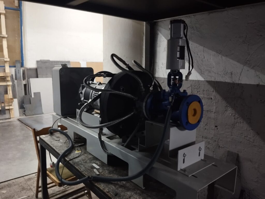
In a microturbine CHP plant, the steam turbine does not typically serve as a main component because these systems are generally based on direct gas turbine cycles. However, in some advanced or hybridized configurations where microturbines are coupled with small-scale steam cycles, a steam turbine can be included to capture additional value from the exhaust heat. In these cases, the microturbine exhaust gases, which leave the combustor and turbine at very high temperatures, are directed into a compact heat recovery unit where they generate steam. This steam can then be routed to a small steam turbine, which produces supplementary electricity or mechanical power while also supplying heat for CHP applications.
The use of a steam turbine in such setups enhances overall system efficiency by turning what would otherwise be wasted thermal energy into productive work. Although microturbines on their own already reach efficiencies suitable for distributed generation, the integration of a steam turbine allows them to approach the efficiency levels of combined cycle systems on a smaller scale. This makes the hybrid microturbine–steam turbine configuration especially attractive in industrial or commercial environments where both electricity and large amounts of process steam or hot water are needed.
The steam turbine itself functions in the same way as in larger power plants but at a reduced scale. Steam is expanded through the turbine blades, causing the rotor to spin and drive a generator or mechanical equipment. The design may use backpressure turbines, where steam exits at a higher pressure for direct process use, or condensing turbines, where steam is expanded to a vacuum and condensed, maximizing power output. In CHP applications, backpressure turbines are often favored because they can simultaneously produce electricity and deliver steam to industrial processes, district heating networks, or absorption chillers.
By incorporating a steam turbine, the microturbine CHP plant achieves a more complete use of the fuel’s energy potential, aligning with the goals of sustainability, cost-effectiveness, and reduced environmental footprint. This additional layer of efficiency also increases the flexibility of the system, enabling it to meet diverse energy demands more effectively. While not standard in all microturbine CHP installations, steam turbines represent a valuable upgrade path in contexts where maximizing energy recovery and thermal utilization are top priorities.
The steam turbine, when incorporated into a microturbine CHP configuration, serves as an additional stage of energy conversion that helps extract the maximum possible value from the fuel being consumed. While the microturbine itself converts fuel into electricity and hot exhaust gases, the steam turbine takes this concept a step further by transforming the high-temperature exhaust into usable steam and then expanding that steam to generate more electricity. This process does not interfere with the primary function of the microturbine but rather complements it, adding a layer of efficiency that brings the overall system performance closer to what is achieved in larger-scale combined cycle plants.
The value of the steam turbine in this context lies not only in the production of additional electricity but also in the flexible use of the steam itself. In many installations, the steam is not fully condensed but instead used directly for industrial heating, sterilization, drying, or other process needs. In district energy systems, it can be distributed for residential or commercial heating, which makes the system highly versatile. The combination of electricity and steam from a compact microturbine-plus-steam turbine setup can significantly reduce the reliance on external boilers or grid electricity, providing a more autonomous and resilient energy solution for the facility.
Another important advantage of integrating a steam turbine into a microturbine CHP plant is the environmental benefit. By making full use of the exhaust energy that would otherwise be wasted, the overall carbon footprint of the system is reduced. The same amount of fuel yields more useful energy, which means less fuel is required per unit of electricity and heat delivered. This aligns with global efforts to improve energy efficiency and reduce greenhouse gas emissions, while also meeting the increasingly strict regulatory standards for energy systems.
From a technical perspective, the design of the steam turbine in these smaller applications is often simplified compared to large utility-scale turbines. The focus is on compactness, reliability, and compatibility with the lower steam flow rates typical of microturbine exhaust heat recovery systems. Engineers may employ single-stage turbines or small multi-stage designs depending on the amount of steam available and the desired output. The materials and construction are optimized to handle frequent cycling and partial load operation, which are common in distributed generation scenarios where energy demand fluctuates throughout the day.
Ultimately, the steam turbine in a microturbine CHP plant represents a bridge between traditional gas turbine technology and more complex combined cycle designs. It demonstrates how even small-scale systems can achieve high efficiencies through clever integration of components. While not present in all microturbine-based CHP systems, where it is used, it transforms the plant into a more complete and sustainable energy solution that delivers significant economic and environmental benefits.
In a microturbine CHP system that incorporates a steam turbine, the flow of energy from the microturbine’s exhaust into the steam cycle is carefully managed to maximize efficiency and output. The high-temperature exhaust gases from the microturbine are routed into a heat recovery unit, where water or another working fluid absorbs the thermal energy and converts it into steam. This steam then enters the steam turbine, where it expands through the turbine blades, transferring its energy to the rotor and generating additional mechanical power. This mechanical energy is either converted into electricity via a coupled generator or used directly for industrial processes, heating, or district energy applications, depending on the configuration. The process effectively captures energy that would otherwise be lost to the environment, improving the overall fuel-to-energy conversion ratio.
The steam turbine in this setup is designed to operate efficiently under the specific conditions created by microturbine exhaust. Because the flow rate and temperature of the steam are generally lower than those in large-scale combined cycle plants, the steam turbine is compact and optimized for partial-load operation. Many designs favor backpressure or extraction turbines, which allow the steam to be used directly for heating purposes while still producing electricity. This dual-purpose operation makes microturbine CHP systems with integrated steam turbines highly versatile, allowing facilities to tailor energy production to both electrical and thermal demand.
One of the key benefits of using a steam turbine in a microturbine CHP system is the increase in overall system efficiency. Microturbines alone can reach electrical efficiencies of 25–35 percent, but by recovering the exhaust heat to produce steam and generate additional power, total system efficiencies can rise to 65–80 percent or higher when both heat and electricity are utilized. This makes the integration of a steam turbine especially attractive in facilities with high thermal loads, such as hospitals, hotels, industrial plants, or district heating networks, where the recovered heat is immediately valuable and reduces the need for additional fuel consumption.
The operation of the steam turbine also contributes to environmental performance. By utilizing energy that would otherwise be wasted, the system reduces fuel usage per unit of energy delivered, lowering greenhouse gas emissions and improving the carbon footprint of the facility. Additionally, because the steam cycle can operate in parallel with the microturbine, the system can maintain stable and reliable output even under varying loads, ensuring that both electrical and thermal demands are met efficiently and safely.
Overall, the steam turbine in a microturbine CHP plant represents a crucial enhancement that leverages exhaust heat for additional energy production and thermal utilization. Its integration allows microturbine systems to achieve higher overall efficiencies, greater fuel economy, and improved environmental performance, turning a compact distributed generation solution into a versatile and sustainable energy source capable of meeting both electricity and heat demands effectively.
In a microturbine CHP plant that incorporates a steam turbine, the steam cycle adds an important layer of energy recovery that significantly enhances the system’s overall performance. After the microturbine converts fuel into electricity and produces high-temperature exhaust gases, this thermal energy is captured in a heat recovery unit and converted into steam. The steam is then directed to the turbine, where it expands through the blades, generating additional mechanical power. This energy is typically converted into electricity through a coupled generator, but the steam can also be used directly for heating, hot water, or industrial processes, allowing the system to serve multiple purposes simultaneously. The integration of the steam turbine ensures that almost every unit of fuel energy is put to productive use rather than being lost as waste heat.
The steam turbine in these microturbine-based CHP systems is specifically engineered to operate under the lower pressure and temperature conditions characteristic of exhaust heat recovery. Unlike large-scale utility steam turbines, these units are compact and optimized for variable loads, allowing them to efficiently handle fluctuations in energy demand without sacrificing performance. Many designs use backpressure or extraction turbines, which release steam at a controlled pressure for immediate thermal use. This dual functionality ensures that both electricity and heat are delivered efficiently, maximizing the economic and operational benefits of the plant.
Efficiency gains from integrating a steam turbine are substantial. While standalone microturbines typically achieve electrical efficiencies in the range of 25–35%, adding a steam turbine and capturing waste heat can increase total system efficiency to 65–80% when both electricity and thermal energy are utilized. This makes the system especially valuable in applications with significant thermal loads, such as hospitals, industrial plants, hotels, or district heating networks. By using the steam effectively, the plant reduces the need for additional fuel-fired boilers, cutting operating costs and improving sustainability.
The presence of a steam turbine also has positive environmental implications. By extracting additional energy from the microturbine exhaust, fuel consumption per unit of usable energy is reduced, lowering greenhouse gas emissions and the overall carbon footprint of the installation. The turbine operates in tandem with the microturbine, maintaining reliable electricity and heat output even when energy demands vary throughout the day. This reliability is a key advantage in commercial or industrial settings where consistent energy supply is critical.
Overall, the steam turbine in a microturbine CHP system transforms exhaust heat into an additional source of electricity and usable thermal energy, enhancing the plant’s overall efficiency, cost-effectiveness, and environmental performance. Its integration allows the system to meet both electrical and thermal energy demands with a compact, flexible, and sustainable solution, making it an ideal choice for facilities seeking efficient combined heat and power generation.
Electric Generator
The electric generator in a microturbine CHP plant is the component that converts the mechanical energy produced by the turbine into usable electrical energy. In these systems, the turbine rotor, driven either by expanding combustion gases or by an integrated steam turbine in hybrid configurations, rotates at very high speeds, and this rotational motion is transferred directly to the generator. Most microturbine generators are either high-speed permanent magnet types or high-speed induction generators, designed to efficiently convert mechanical energy into electricity with minimal losses. The generator’s ability to produce stable voltage and frequency is crucial, as it determines whether the electricity can be used on-site, fed into a local grid, or synchronized with other energy sources.
The integration of the generator with the turbine in microturbine CHP systems is highly compact, often sharing the same shaft, which reduces mechanical complexity and energy losses. Because microturbines operate at very high rotational speeds, the generator must be engineered to handle these conditions while maintaining durability and efficiency. High-speed operation allows the generator to be smaller and lighter than conventional low-speed units, which is ideal for distributed generation applications where space is limited. The design also often includes advanced cooling systems, such as air or liquid cooling, to prevent overheating and ensure continuous operation even under high load conditions.
Electric generators in microturbine CHP plants are also designed for flexibility and reliability. They can operate in standalone mode, providing electricity directly to the facility, or in parallel with the grid. Control systems monitor the generator output, adjusting turbine speed and fuel supply to maintain consistent voltage, frequency, and power quality. This capability is particularly important in applications where sensitive equipment is used, such as hospitals, data centers, or industrial processes, ensuring uninterrupted and high-quality power.
Another important aspect of the generator in microturbine CHP systems is its compatibility with hybrid configurations. When a steam turbine is added to capture exhaust heat, the generator must accommodate variable torque inputs while maintaining stable electrical output. The integration of both turbines with a single generator or multiple synchronized generators allows the system to maximize overall energy conversion efficiency, producing both electricity and thermal energy simultaneously without wasting fuel.
Overall, the electric generator is the core of energy output in a microturbine CHP plant. Its precise engineering, high-speed design, and integration with turbine systems ensure that mechanical energy from combustion and steam cycles is reliably converted into electricity. This enables the plant to deliver stable power to the facility or grid while complementing the heat recovery process, making the system highly efficient, versatile, and sustainable for distributed combined heat and power applications.
The electric generator in a microturbine CHP plant serves as the critical interface between mechanical energy and usable electrical power. As the turbine rotates, driven by high-pressure combustion gases or, in hybrid systems, supplemented by a steam turbine, the generator converts this rotational energy into electricity. Microturbine generators are typically high-speed permanent magnet or high-speed induction types, designed to operate efficiently at the very high rotational speeds characteristic of microturbines. The generator must produce stable voltage and frequency, which is essential for either on-site consumption, connection to a local grid, or parallel operation with other power sources. Its performance directly affects the reliability and quality of the electricity delivered.
In microturbine CHP systems, the generator is often mounted directly on the same shaft as the turbine. This compact integration minimizes energy losses, reduces the overall footprint of the system, and simplifies maintenance compared to separate, low-speed generator configurations. High-speed operation allows the generator to be much smaller and lighter, which is particularly advantageous in commercial or industrial environments where space is at a premium. Despite its compactness, the generator is engineered to withstand continuous operation under high mechanical and thermal stress, often using advanced cooling methods such as forced air or liquid cooling to prevent overheating and ensure long-term reliability.
The generator also plays a key role in the flexibility and adaptability of microturbine CHP systems. It can function independently to supply electricity directly to a facility, or it can operate in grid-tied mode, synchronizing with external power sources to provide stable and high-quality power. Modern control systems continuously monitor generator output, adjusting turbine speed and fuel flow to maintain consistent voltage, frequency, and power quality, even under fluctuating loads. This capability is particularly important for facilities with sensitive electrical equipment, such as hospitals, data centers, or manufacturing processes, where any interruption or voltage fluctuation could have significant consequences.
In hybrid systems that include a steam turbine for exhaust heat recovery, the generator must accommodate variable torque inputs from both turbines while still maintaining steady electrical output. This requires sophisticated engineering and precise control algorithms, ensuring that electricity production is smooth and continuous. By effectively converting mechanical energy from both the primary microturbine and the supplemental steam turbine, the generator helps maximize the overall energy efficiency of the CHP system, allowing both electricity and thermal energy to be delivered simultaneously with minimal fuel waste.
Overall, the electric generator is the heart of a microturbine CHP plant’s electrical output. Its high-speed design, robust construction, and seamless integration with turbine systems enable the reliable conversion of mechanical energy into electricity. This capability supports stable power delivery for the facility or grid while complementing the heat recovery processes, enhancing the efficiency, flexibility, and sustainability of microturbine combined heat and power applications.
The electric generator in a microturbine CHP plant is central to the system’s function, converting the mechanical energy produced by the turbine into usable electricity. As the microturbine spins at extremely high speeds, the generator transforms this rotational energy into electrical energy that can be used on-site, fed into a local grid, or synchronized with other power sources. The high-speed operation of microturbine generators allows for a compact and lightweight design, which is critical in distributed generation applications where space is limited. Despite their small size, these generators are engineered to deliver reliable and consistent voltage and frequency, ensuring that both the facility and connected equipment receive stable power.
Integration of the generator with the turbine is a key factor in efficiency. In most microturbine CHP systems, the generator is mounted directly on the same shaft as the turbine, eliminating the need for separate coupling mechanisms and reducing energy losses. This direct-drive configuration simplifies maintenance and improves overall system reliability. Advanced cooling methods, such as air or liquid cooling, are typically incorporated to maintain optimal operating temperatures, preventing overheating and ensuring continuous performance even during long operational cycles. The durability of the generator is crucial, as it often operates for thousands of hours per year under varying load conditions.
Another critical aspect of the electric generator is its role in system flexibility. Microturbine CHP plants may operate independently or in parallel with the grid, and the generator must adapt to changes in load demand while maintaining steady output. Sophisticated control systems monitor generator performance in real time, adjusting turbine speed and fuel flow to maintain consistent power quality. This capability is particularly valuable in environments with sensitive electrical equipment, such as hospitals, industrial facilities, or data centers, where uninterrupted power and stable voltage are essential.
In hybrid systems where a steam turbine is used to recover exhaust heat from the microturbine, the generator must accommodate variable torque inputs from both turbines while maintaining stable electrical output. By effectively managing energy from both sources, the generator enables the plant to achieve higher overall efficiency, converting more of the fuel’s energy into electricity and usable heat. This dual-source operation maximizes the value of the fuel consumed, reduces waste, and supports sustainable energy production.
Overall, the electric generator in a microturbine CHP plant is not just a component but the core of the system’s electrical output. Its high-speed design, robust construction, and integration with the turbine system ensure that mechanical energy is reliably transformed into electricity, supporting both on-site power needs and grid-tied operations. By enabling stable, efficient, and flexible electricity generation, the generator plays a vital role in the success and sustainability of microturbine combined heat and power systems.
The electric generator in a microturbine CHP plant is fundamental to transforming the turbine’s mechanical motion into electricity that can be utilized for a facility’s power needs or exported to the grid. As the turbine spins at extremely high speeds, the generator converts this mechanical energy into a controlled electrical output with consistent voltage and frequency. This conversion must be highly efficient because the overall system efficiency of a microturbine CHP plant relies on minimizing losses at every stage. Modern microturbine generators are often high-speed permanent magnet types or specially designed induction generators that are capable of handling the rapid rotations of the turbine while maintaining stable performance.
Direct integration with the turbine shaft allows the generator to operate without additional gears or coupling mechanisms, reducing energy losses and simplifying the system’s mechanical layout. This configuration also helps minimize vibration and wear, contributing to longer service intervals and reduced maintenance requirements. Despite the small footprint of a microturbine CHP plant, the generator is engineered to endure continuous operation under variable loads, which is common in commercial or industrial applications where energy demand fluctuates throughout the day. Cooling systems, whether forced-air or liquid-cooled, ensure that the generator maintains optimal operating temperatures, preventing overheating and preserving longevity.
Flexibility is another key advantage of the microturbine generator. It can operate in standalone mode, supplying power directly to on-site equipment, or synchronize with the grid to provide electricity to multiple consumers. Control systems continuously monitor the generator’s performance, adjusting turbine speed and fuel flow to maintain precise voltage and frequency. This capability is especially important in facilities with sensitive electrical equipment, such as hospitals, laboratories, or data centers, where even small fluctuations in power quality could have serious consequences. The generator must respond rapidly to changes in demand while maintaining output stability, which highlights its critical role in overall system reliability.
In hybrid microturbine CHP systems where a steam turbine is included for waste heat recovery, the generator must handle variable torque from multiple sources simultaneously. This requires sophisticated engineering to ensure smooth power output despite changing loads from both the microturbine and the steam turbine. By converting energy from both sources efficiently, the generator helps the system achieve higher overall fuel-to-electricity efficiency while complementing the simultaneous production of heat for CHP applications. This integration maximizes the energy extracted from the fuel, reduces waste, and increases the economic and environmental benefits of the system.
Overall, the electric generator is the central component that enables a microturbine CHP plant to deliver reliable, efficient, and high-quality electricity. Its high-speed operation, robust design, and integration with both turbine and control systems ensure that mechanical energy is consistently converted into usable power. By maintaining stable output, supporting flexible operation, and maximizing energy recovery from both the microturbine and any supplemental steam turbine, the generator plays a decisive role in making microturbine CHP plants effective, sustainable, and versatile energy solutions.
Recuperator / Heat Recovery Unit
The recuperator, or heat recovery unit, in a microturbine CHP plant is a critical component designed to capture and reuse thermal energy from the turbine’s exhaust gases. After combustion, the exhaust leaves the turbine at a high temperature, carrying a significant amount of energy that would otherwise be wasted. The recuperator redirects this hot exhaust air to preheat the compressed intake air before it enters the combustion chamber. By raising the temperature of the incoming air, the system reduces the amount of fuel required to reach the combustion temperature, thereby improving overall efficiency and reducing operational costs. This process allows microturbines to achieve higher electrical efficiencies than would be possible without heat recovery, which is especially important in distributed generation applications where fuel efficiency and emissions control are priorities.
The design of the recuperator is highly specialized to maximize heat transfer while minimizing pressure losses. Typically, these units consist of a network of metal plates or tubes that separate the hot exhaust gases from the cooler intake air, allowing heat to flow between the two streams without mixing them. Materials used in the recuperator must withstand high temperatures and thermal cycling while maintaining structural integrity and corrosion resistance. The compact design is crucial for microturbine applications, as these systems are often installed in confined spaces such as commercial buildings, small industrial facilities, or remote sites where space is limited.
In addition to improving fuel efficiency, the recuperator contributes to environmental performance. By preheating the intake air and reducing the fuel required for combustion, the microturbine produces lower emissions of nitrogen oxides, carbon monoxide, and unburned hydrocarbons. This lean combustion capability enabled by the recuperator is a key factor in the clean operation of microturbine CHP plants, making them suitable for urban environments and facilities with strict emissions standards. The system also allows the microturbine to operate more effectively at partial loads, maintaining efficiency and performance even when the electrical or thermal demand fluctuates.
The recuperator’s role extends beyond just preheating air; in some configurations, it also supports the integration of additional thermal recovery equipment. For example, the exhaust from the recuperator can be routed to a small heat exchanger or steam generator to provide hot water, steam, or heating for industrial processes or district energy systems. This dual use of exhaust energy further enhances the overall efficiency of the CHP plant, turning what would otherwise be waste heat into a valuable resource for the facility. The combination of fuel savings, reduced emissions, and increased usable heat makes the recuperator a cornerstone of microturbine CHP technology.
Ultimately, the recuperator or heat recovery unit transforms the energy profile of a microturbine CHP plant. By capturing exhaust heat and preheating intake air, it increases fuel efficiency, lowers emissions, and enhances the reliability and flexibility of the system. Its compact, high-performance design is essential for achieving the economic and environmental benefits that make microturbines a preferred choice for distributed combined heat and power applications, delivering both electricity and heat with maximum effectiveness.
The recuperator, or heat recovery unit, in a microturbine CHP plant plays a vital role in maximizing the system’s energy efficiency by capturing waste heat from the turbine exhaust and using it to preheat the compressed intake air. After combustion, the exhaust gases leave the turbine at high temperatures, containing a significant amount of energy that would otherwise be lost to the environment. The recuperator redirects this heat to the incoming air, raising its temperature before it enters the combustion chamber. This preheating reduces the fuel required to reach the necessary combustion temperature, improving overall thermal efficiency and lowering operational costs. By recovering energy that would otherwise be wasted, the recuperator allows microturbines to achieve electrical efficiencies of 25–35% or more, with total system efficiency reaching up to 80% when combined with CHP operations.
The design of the recuperator is highly optimized to ensure maximum heat transfer while minimizing pressure losses in the airflow. It typically consists of metal plates or tubular structures that separate the hot exhaust stream from the cooler intake air, allowing heat to transfer efficiently without mixing the gases. Materials must be able to withstand repeated thermal cycling, high temperatures, and potential corrosion from exhaust gases, all while maintaining structural integrity. Compactness is essential, as microturbine CHP plants are often installed in confined spaces such as commercial buildings, small industrial sites, or remote energy installations. The recuperator must deliver high performance without significantly increasing the footprint or complexity of the system.
In addition to improving fuel efficiency, the recuperator contributes to environmental performance by enabling lean combustion, which reduces emissions of nitrogen oxides, carbon monoxide, and unburned hydrocarbons. Preheating the intake air allows the combustor to operate at lower fuel-to-air ratios while still achieving complete combustion, minimizing pollutants and ensuring the system meets stringent emissions regulations. This capability also allows the microturbine to maintain efficiency under varying loads, making it flexible for facilities where energy demand fluctuates throughout the day.
Beyond preheating the intake air, the recuperator often serves as a key component in thermal integration for CHP applications. The exhaust gases leaving the recuperator can be further directed into heat exchangers to produce hot water, steam, or heating for industrial processes, district heating, or other thermal applications. This dual use of the exhaust stream ensures that almost all of the energy from the fuel is utilized, turning the microturbine into a highly efficient source of both electricity and heat. By leveraging the recuperator, microturbine CHP systems reduce fuel consumption, lower operating costs, and increase overall energy productivity.
Overall, the recuperator or heat recovery unit is indispensable in microturbine CHP plants. It transforms exhaust heat into a valuable resource, improves fuel efficiency, supports cleaner combustion, and enhances the system’s ability to meet both electrical and thermal demands. Its integration into the microturbine design ensures that energy is used effectively, emissions are minimized, and the system operates reliably and sustainably in a wide range of distributed generation applications.
The recuperator in a microturbine CHP plant is a key element in achieving high overall efficiency by capturing the energy contained in the turbine’s exhaust gases and reusing it to preheat incoming air for combustion. After the turbine extracts mechanical energy from the hot gases produced in the combustor, a large portion of thermal energy remains in the exhaust stream. The recuperator channels this hot exhaust through a series of metal plates or tubes that transfer the heat to the compressed intake air before it enters the combustion chamber. By raising the temperature of the intake air, the combustor requires less fuel to reach ignition temperatures, directly improving fuel efficiency and reducing operating costs while maintaining stable and reliable power output.
The engineering of the recuperator focuses on maximizing heat transfer while minimizing pressure drop across the unit. Microturbine CHP systems are often installed in compact spaces, so the recuperator must be designed to deliver high thermal performance without occupying excessive volume. Materials used in the heat recovery unit are carefully selected to withstand high temperatures, thermal cycling, and potential corrosion from exhaust gases, ensuring long-term durability and minimal maintenance. Its design also helps the system operate efficiently across varying loads, allowing the microturbine to respond to fluctuating electrical and thermal demands while maintaining high efficiency.
Environmental benefits are another critical advantage of the recuperator. By preheating the intake air and enabling lean combustion, the unit helps reduce emissions of nitrogen oxides, carbon monoxide, and unburned hydrocarbons. Lean-burn operation facilitated by the recuperator ensures that fuel is used effectively while minimizing harmful byproducts, making microturbine CHP plants suitable for urban or industrial installations with strict emissions regulations. The combination of improved fuel efficiency and reduced emissions enhances both the economic and environmental performance of the system.
The recuperator also serves as a stepping stone for further thermal energy utilization. Exhaust gases leaving the recuperator can be directed to heat exchangers or small steam generators, providing hot water, steam, or process heat for industrial applications or district heating systems. This allows the microturbine CHP plant to deliver combined heat and power efficiently, converting nearly all of the fuel’s energy into useful outputs. By fully exploiting the exhaust heat, the system reduces fuel consumption, cuts operational costs, and increases overall energy productivity.
In summary, the recuperator or heat recovery unit is a vital component that transforms otherwise wasted exhaust energy into a valuable resource for preheating intake air and supporting CHP applications. Its ability to enhance fuel efficiency, support cleaner combustion, and enable thermal energy recovery makes it central to the performance, sustainability, and economic viability of microturbine CHP plants. By integrating a well-designed recuperator, these systems achieve high efficiency, lower emissions, and reliable delivery of both electricity and heat, making them an ideal solution for distributed energy applications.
The recuperator in a microturbine CHP plant is essential for optimizing energy efficiency by capturing and reusing the heat from turbine exhaust gases. After the turbine converts high-temperature combustion gases into mechanical energy, the exhaust still contains substantial thermal energy. The recuperator channels this hot exhaust through a series of metal plates or tubes, transferring its heat to the compressed intake air before it enters the combustion chamber. Preheating the intake air reduces the amount of fuel needed to achieve the combustion temperature, increasing overall efficiency and lowering fuel consumption. This process allows the microturbine to produce more electricity from the same amount of fuel while simultaneously supporting CHP operations through recovered heat.
The design of the recuperator is highly engineered to balance effective heat transfer with minimal pressure losses. Microturbine CHP plants are compact by nature, so the heat recovery unit must deliver maximum thermal performance without significantly increasing the system footprint. Materials are chosen to withstand high temperatures, repeated thermal cycling, and potential corrosion from exhaust gases. The arrangement of plates or tubes ensures that heat is transferred efficiently, maintaining consistent airflow and preventing hotspots that could affect turbine performance or lifespan. This careful design allows the microturbine to operate efficiently at varying loads, providing reliable electricity and heat even when demand fluctuates.
In addition to improving fuel efficiency, the recuperator plays a critical role in environmental performance. By preheating the intake air, it supports lean combustion, which reduces emissions of nitrogen oxides, carbon monoxide, and unburned hydrocarbons. The ability to maintain efficient combustion at lower fuel-to-air ratios ensures cleaner operation, making microturbine CHP systems suitable for urban installations or facilities with strict emissions regulations. The combination of energy savings and lower emissions enhances both economic and environmental outcomes, reinforcing the system’s sustainability.
The recuperator also contributes to maximizing the usable thermal output of the system. The exhaust gases leaving the recuperator can be directed to additional heat exchangers, boilers, or steam generators to provide hot water, steam, or process heat for industrial applications or district heating networks. This multi-stage use of exhaust energy ensures that nearly all of the fuel’s energy is converted into useful output, reducing waste and operational costs. By capturing and redirecting heat, the recuperator transforms microturbine CHP plants into highly efficient combined heat and power systems capable of meeting both electrical and thermal energy demands.
Overall, the recuperator or heat recovery unit is a cornerstone of microturbine CHP plant performance. Its ability to capture exhaust heat, preheat intake air, and support thermal energy recovery improves fuel efficiency, reduces emissions, and maximizes overall system output. By enabling more complete use of the fuel’s energy, the recuperator ensures that microturbine CHP systems operate sustainably, efficiently, and reliably, providing both electricity and heat in an optimized and environmentally responsible manner.
Control System
The control system in a microturbine CHP plant is the central hub that ensures all components operate safely, efficiently, and in harmony. It continuously monitors the performance of the turbine, generator, recuperator, and any additional subsystems such as steam turbines or heat recovery units. By analyzing data from numerous sensors, the control system can adjust fuel flow, turbine speed, and airflow to maintain optimal operating conditions. This real-time regulation ensures that electricity and thermal output remain stable even when the energy demand fluctuates, allowing the plant to meet varying loads while maintaining efficiency and reliability.
Modern control systems in microturbine CHP plants use advanced algorithms to manage multiple operational parameters simultaneously. They regulate temperature, pressure, and rotational speed, as well as manage startup, shutdown, and emergency procedures. The system can detect abnormal conditions such as high exhaust temperatures, pressure drops, or fuel supply issues and respond immediately to prevent damage or unsafe operation. This level of automation not only increases safety but also reduces the need for continuous human oversight, allowing the plant to run unattended for long periods while maintaining performance standards.
The control system also plays a crucial role in integrating the microturbine with the electrical grid or with other on-site energy sources. It ensures synchronization with the grid, maintaining proper voltage and frequency, and can manage load sharing when multiple generators or turbines operate in parallel. For CHP applications, the control system coordinates the balance between electricity generation and heat production, optimizing overall efficiency. By monitoring thermal output, it can modulate turbine operation or activate auxiliary systems to meet the facility’s heating or hot water requirements without compromising electrical performance.
Additionally, the control system provides diagnostic and reporting capabilities. It logs operational data, monitors long-term performance trends, and alerts operators to maintenance needs before failures occur. This predictive functionality extends equipment lifespan and minimizes downtime, ensuring continuous energy supply. Remote monitoring is also a common feature, allowing plant operators to access real-time data, adjust settings, and respond to alerts from anywhere, further enhancing operational flexibility and reliability.
Overall, the control system is the brain of a microturbine CHP plant, coordinating all functions to maintain optimal performance, safety, and efficiency. Its ability to manage complex interactions between mechanical, thermal, and electrical subsystems allows the plant to deliver reliable electricity and heat while minimizing fuel consumption and emissions. By providing automation, protection, and monitoring, the control system ensures that microturbine CHP plants operate smoothly, efficiently, and sustainably under a wide range of conditions.
The control system in a microturbine CHP plant is the core component that ensures all parts of the system work together efficiently and safely. It continuously monitors key parameters such as turbine speed, fuel flow, exhaust temperature, and generator output, making real-time adjustments to maintain optimal performance. By regulating these variables, the control system ensures that both electricity and thermal energy production remain stable even when energy demand fluctuates, which is essential for maintaining the reliability of the facility’s power and heat supply. This constant supervision allows the plant to operate efficiently across a wide range of loads, maximizing fuel utilization and minimizing waste.
Modern control systems employ sophisticated algorithms that coordinate multiple subsystems simultaneously. They manage the operation of the turbine, generator, recuperator, and any integrated heat recovery or steam generation units, ensuring that each component functions within safe and efficient limits. The system can automatically adjust fuel-air ratios, modulate turbine speed, and control airflow to optimize combustion and energy conversion. In addition, it handles startup and shutdown sequences, emergency responses, and fault detection, providing protection against conditions that could damage the equipment or compromise safety. This automation reduces the need for constant human intervention, allowing the plant to operate reliably and safely over extended periods.
The control system also enables integration with the electrical grid or other on-site power sources. It ensures that the generator maintains the proper voltage and frequency for grid connection, manages synchronization with other generators, and can allocate load sharing in multi-unit installations. In CHP applications, the system balances electrical and thermal outputs, ensuring that heat recovery is maximized without compromising electricity production. By monitoring thermal demand and adjusting turbine operation or auxiliary systems, the control system ensures that both power and heat are delivered efficiently, adapting to changing energy needs in real time.
Additionally, the control system provides advanced diagnostics and monitoring capabilities. It logs operational data, tracks performance trends, and generates alerts for maintenance needs before failures occur, supporting predictive maintenance strategies. Many systems also offer remote access, enabling operators to monitor performance, adjust settings, and respond to alerts from off-site locations. This capability enhances operational flexibility, reduces downtime, and ensures continuous energy delivery, even in facilities where staffing is limited.
Overall, the control system functions as the brain of a microturbine CHP plant, coordinating mechanical, electrical, and thermal processes to optimize efficiency, safety, and reliability. Its ability to continuously monitor, adjust, and protect the system allows the plant to provide consistent electricity and heat, maintain stable operation under varying loads, and achieve high fuel efficiency. By integrating automation, monitoring, and diagnostics, the control system ensures that microturbine CHP plants operate smoothly and sustainably, meeting both energy and environmental goals.
The control system in a microturbine CHP plant is the central mechanism that ensures the entire system operates efficiently, safely, and reliably. It constantly monitors turbine performance, generator output, fuel flow, exhaust temperatures, and other critical parameters, making real-time adjustments to optimize both electricity and heat production. By continuously regulating these variables, the control system allows the plant to respond to fluctuations in demand while maintaining stable energy output, ensuring that facilities receive consistent power and thermal energy even under variable operating conditions. This capability is crucial for achieving maximum fuel efficiency and minimizing operational waste.
Advanced control systems use sophisticated algorithms to coordinate all subsystems within the microturbine CHP plant. They manage the operation of the turbine, generator, and any heat recovery units, adjusting fuel-air mixtures, turbine speed, and airflow to maintain optimal combustion and energy conversion. The system also oversees startup and shutdown procedures, emergency responses, and fault detection, automatically intervening to prevent damage or unsafe operation. This automation reduces the need for constant human supervision, allowing the plant to run reliably over long periods and maintain performance without frequent manual intervention.
The control system is also responsible for integrating the microturbine with the electrical grid or other energy sources on-site. It ensures proper synchronization, maintaining consistent voltage and frequency, and manages load sharing when multiple generators or turbines operate in parallel. In CHP applications, the control system balances electricity generation and heat production, adjusting turbine operation and auxiliary systems to meet changing thermal demands while keeping electrical output stable. This balance maximizes overall system efficiency, ensuring that both power and heat are delivered in the right proportions for the facility’s needs.
In addition to operational management, the control system provides extensive monitoring and diagnostic capabilities. It records operational data, tracks performance trends, and generates maintenance alerts before issues can cause downtime or damage. Many systems allow for remote monitoring, giving operators the ability to adjust settings, respond to alarms, and oversee plant performance from off-site locations. This feature increases operational flexibility and reliability, allowing microturbine CHP plants to maintain continuous energy supply even with minimal on-site staff.
Overall, the control system acts as the brain of the microturbine CHP plant, coordinating the interaction between mechanical, electrical, and thermal components to maintain optimal performance. Its real-time monitoring, automation, and diagnostic functions ensure stable electricity and heat output, maximize fuel efficiency, and protect equipment from damage. By managing the complex interplay of components, the control system enables microturbine CHP plants to operate smoothly, efficiently, and sustainably, delivering reliable energy while minimizing environmental impact.
The control system in a microturbine CHP plant is essential for maintaining seamless and efficient operation of the entire system. It continuously monitors key parameters such as turbine speed, generator output, fuel flow, exhaust temperature, and intake air conditions, making real-time adjustments to keep the plant running at optimal efficiency. By regulating these variables, the control system ensures that electricity generation and heat recovery are balanced according to the facility’s demands, allowing the plant to adapt dynamically to fluctuating loads while maintaining stable performance. This capability is critical for achieving high overall efficiency and ensuring that both electrical and thermal outputs are reliably delivered.
Modern microturbine CHP control systems employ sophisticated algorithms to manage multiple subsystems simultaneously. They adjust turbine speed, fuel injection, and airflow to optimize combustion and energy conversion while minimizing emissions. The system also coordinates the operation of heat recovery units, steam turbines (if present), and auxiliary equipment, ensuring that each component operates within safe and efficient limits. Startup, shutdown, and emergency procedures are also managed automatically, allowing the plant to respond quickly to abnormal conditions such as high exhaust temperatures, pressure deviations, or fuel supply interruptions. This automation reduces the need for constant human supervision and enhances operational safety and reliability.
Another critical function of the control system is its role in grid integration and energy distribution. It ensures that the generator maintains consistent voltage and frequency when connected to the grid and manages load sharing if multiple units operate in parallel. In CHP applications, the control system balances electrical production with thermal output, adjusting turbine and auxiliary system operation to meet the facility’s heating or hot water requirements without compromising electricity generation. This integrated management maximizes energy utilization and ensures that the system operates efficiently under varying operational conditions.
The control system also provides comprehensive monitoring, diagnostic, and reporting capabilities. It logs operational data, tracks performance trends, and can predict maintenance needs before failures occur, supporting proactive maintenance strategies that reduce downtime and extend equipment life. Remote monitoring capabilities allow operators to access real-time system performance data, make adjustments, and respond to alerts from off-site locations, adding flexibility and enhancing reliability.
Overall, the control system serves as the central nervous system of a microturbine CHP plant, coordinating mechanical, electrical, and thermal components to maintain optimal performance. Its continuous monitoring, automation, and diagnostic functions ensure stable and efficient energy production, protect equipment from damage, and maximize the use of fuel for both electricity and heat generation. By enabling precise control and intelligent management of the entire system, the control system ensures that microturbine CHP plants operate sustainably, efficiently, and reliably under a wide range of conditions.
Auxiliary systems in a microturbine CHP plant are essential components that support the primary functions of electricity and heat generation, ensuring reliable and continuous operation. These systems include fuel supply and conditioning equipment, lubrication and cooling systems, air filtration units, and exhaust management components. Each auxiliary system is designed to maintain the optimal operating conditions of the microturbine, generator, recuperator, and any integrated heat recovery or steam units, allowing the plant to operate efficiently and safely. Without properly functioning auxiliary systems, the main energy conversion equipment could be exposed to overheating, contamination, or mechanical wear, which would reduce performance and increase maintenance requirements.
Fuel supply systems are a critical part of the auxiliary infrastructure. They ensure that the microturbine receives a consistent and clean fuel source, whether natural gas, biogas, or liquid fuel. Fuel is often filtered, pressurized, and metered precisely to maintain steady combustion and prevent damage to the turbine components. Similarly, lubrication systems provide continuous oil circulation to the bearings and moving parts of the turbine and generator, reducing friction, preventing wear, and supporting long-term operational reliability. These systems are equipped with monitoring and safety mechanisms to detect low oil levels, temperature variations, or pressure drops, automatically initiating alarms or shutdowns if needed.
Cooling systems are another vital auxiliary component, as microturbines and generators generate significant heat during operation. These systems use air or liquid to remove excess heat from critical components, maintaining temperature within safe limits and preventing thermal stress. Heat exchangers, fans, pumps, and coolant circuits work together to dissipate heat effectively, ensuring stable operation and prolonging the lifespan of key equipment. Air filtration units, meanwhile, protect the microturbine from particulate contamination that could damage the compressor or combustion chamber, further enhancing reliability.
Exhaust management and emission control systems are also part of the auxiliary setup, ensuring that the exhaust gases are safely directed away from the plant and, in many cases, treated to reduce pollutants. This includes silencers, catalytic converters, or selective catalytic reduction units, which help the plant comply with environmental regulations and minimize its carbon footprint. Additional auxiliary systems may include instrumentation, sensors, valves, and pumps that support fluid circulation, fuel delivery, and monitoring throughout the plant.
Overall, auxiliary systems are the backbone of a microturbine CHP plant, enabling the main energy-producing components to operate efficiently, safely, and reliably. By maintaining proper fuel supply, lubrication, cooling, air quality, and exhaust treatment, these systems ensure that the microturbine and associated equipment can deliver stable electricity and heat output. Their integration and proper functioning are critical for maximizing system performance, minimizing downtime, and extending the service life of the plant, making them indispensable to the overall success of a microturbine CHP installation.
Auxiliary systems in a microturbine CHP plant play a crucial role in supporting the operation of the main energy-producing components, ensuring the plant runs efficiently, safely, and reliably. These systems include fuel handling and conditioning equipment, lubrication and cooling systems, air filtration units, exhaust management, and other supporting subsystems. Each auxiliary system is designed to maintain the optimal operating conditions for the turbine, generator, recuperator, and any additional heat recovery or steam systems. By doing so, they help prevent mechanical wear, overheating, and performance losses, ensuring that the plant can deliver stable electricity and heat over long periods of operation.
Fuel supply and conditioning systems are essential to maintaining consistent and clean combustion. In microturbine CHP plants, fuels such as natural gas, biogas, or liquid fuels are filtered, pressurized, and precisely metered to ensure the turbine receives the correct fuel flow. This not only guarantees efficient combustion but also protects the turbine and combustor from contamination or damage. Lubrication systems complement this by continuously circulating oil to bearings and moving parts, reducing friction and wear, and maintaining smooth operation. These systems are equipped with monitoring and safety mechanisms to detect low oil levels, temperature fluctuations, or pressure drops, allowing the plant to respond immediately to potential issues.
Cooling systems are another critical auxiliary component, as turbines and generators generate significant heat during operation. Air or liquid cooling circuits remove excess heat from critical components, preventing overheating and maintaining stable operating temperatures. Heat exchangers, pumps, fans, and coolant circuits work together to dissipate heat efficiently, extending the lifespan of key components and enhancing overall reliability. Air filtration units further protect the turbine by removing dust and other particles from the intake air, preventing damage to the compressor and combustion chamber and ensuring consistent performance.
Exhaust and emission control systems are also part of the auxiliary infrastructure, managing the safe release of combustion gases and, in many cases, treating them to reduce pollutants. Silencers, catalytic converters, or selective catalytic reduction units are often employed to meet environmental regulations and minimize the plant’s impact on air quality. Additional supporting systems include instrumentation, sensors, valves, and pumps that facilitate fuel delivery, fluid circulation, and system monitoring, ensuring all subsystems operate cohesively.
Overall, auxiliary systems are indispensable for the smooth operation of a microturbine CHP plant. By maintaining proper fuel supply, lubrication, cooling, air quality, and exhaust management, they allow the turbine and associated equipment to operate at peak efficiency and reliability. Their integration ensures that the plant can continuously provide electricity and heat while minimizing maintenance needs, operational downtime, and fuel waste. In essence, the auxiliary systems form the backbone that supports the primary energy generation processes, making the entire CHP system efficient, sustainable, and dependable.
Auxiliary systems in a microturbine CHP plant are fundamental to ensuring the smooth and reliable operation of the entire facility. These systems work quietly in the background, supporting the turbine, generator, and heat recovery components by maintaining optimal conditions for performance and longevity. They include fuel supply and conditioning units, lubrication and cooling systems, air filtration devices, and exhaust handling equipment, among others. Each auxiliary system is designed to protect the main equipment from stress, wear, and inefficiency, allowing the plant to deliver consistent electricity and thermal energy while operating safely under varying load conditions.
The fuel handling and conditioning system is critical for providing the turbine with a clean and stable energy source. Whether the plant uses natural gas, biogas, or liquid fuels, the system filters, pressurizes, and meters the fuel precisely to ensure steady combustion. This not only enhances efficiency but also prevents damage to the turbine blades and combustor caused by contaminants or fuel inconsistencies. Lubrication systems complement this by circulating oil to bearings and moving parts, reducing friction, wear, and mechanical stress. These systems often include sensors and alarms to detect low oil levels, temperature spikes, or pressure drops, allowing the plant to take protective measures before any damage occurs.
Cooling systems are another vital component of the auxiliary infrastructure. Microturbines and generators generate substantial heat during operation, and excess temperatures can compromise performance or lead to equipment failure. Air or liquid cooling circuits remove this heat from critical components, maintaining safe operating temperatures. Heat exchangers, pumps, fans, and coolant channels work together to dissipate heat effectively, while air filtration units prevent dust and particles from entering the turbine and affecting performance. By keeping the equipment within optimal temperature ranges, cooling systems extend component life and ensure uninterrupted energy production.
Exhaust management and emission control also form part of the auxiliary setup. Exhaust systems safely direct combustion gases away from the plant while optional catalytic converters, silencers, or selective catalytic reduction units help reduce emissions, ensuring compliance with environmental regulations. Additional auxiliary equipment includes sensors, valves, pumps, and instrumentation that enable continuous monitoring, control, and fluid circulation throughout the plant. These systems work together to maintain stability, efficiency, and safety in real-time operations.
Overall, auxiliary systems are the backbone of a microturbine CHP plant, ensuring that all primary components operate reliably and efficiently. By managing fuel supply, lubrication, cooling, air quality, and exhaust treatment, these systems allow the plant to provide continuous electricity and heat while reducing maintenance needs, operational interruptions, and fuel consumption. Their proper functioning is essential for maximizing overall system performance, protecting equipment, and maintaining sustainable and efficient combined heat and power generation.
Auxiliary systems in a microturbine CHP plant are essential for maintaining continuous, efficient, and safe operation of the primary energy-producing equipment. These systems provide support to the turbine, generator, recuperator, and heat recovery units by ensuring that all operating conditions remain within optimal ranges. They include fuel supply and conditioning systems, lubrication and cooling circuits, air filtration units, exhaust and emission control components, as well as instrumentation and monitoring devices. Each auxiliary system is carefully designed to protect the main equipment, prevent operational disruptions, and maximize the overall efficiency of electricity and heat generation.
The fuel handling and conditioning systems ensure that the turbine receives a clean, stable, and precisely metered fuel supply. Whether using natural gas, biogas, or liquid fuels, these systems filter and regulate the fuel to maintain consistent combustion, reduce mechanical stress on turbine components, and improve overall efficiency. Lubrication systems complement this by circulating oil to bearings and moving parts, reducing friction, wear, and heat buildup. These systems are often equipped with sensors and alarms to detect abnormal conditions such as low oil levels or high temperatures, allowing automatic intervention to protect the plant from potential damage.
Cooling systems are equally critical, as microturbines and generators generate significant heat during operation. Auxiliary cooling circuits use air or liquid to remove excess heat from critical components, ensuring stable operating temperatures and preventing thermal stress. Heat exchangers, pumps, and fans work in tandem to dissipate heat effectively, while air filtration units remove dust and particulate matter from intake air, protecting the compressor and combustion chamber from contamination. These systems help maintain operational efficiency, prolong the lifespan of the turbine and generator, and support consistent energy output under varying load conditions.
Exhaust and emission management systems form another key part of the auxiliary infrastructure. They safely direct hot gases away from the plant and, in many cases, include catalytic converters, silencers, or selective catalytic reduction units to reduce pollutants and meet environmental standards. Additionally, auxiliary systems include instrumentation, sensors, and control valves that enable continuous monitoring and regulation of fluid, air, and fuel flow throughout the plant. These systems ensure that all subsystems operate cohesively, maintaining reliability, efficiency, and safety at all times.
Overall, auxiliary systems are indispensable to the proper functioning of a microturbine CHP plant. They support fuel delivery, lubrication, cooling, air quality, and exhaust management, allowing the turbine, generator, and heat recovery units to operate at peak efficiency. By maintaining stable and optimal operating conditions, auxiliary systems reduce maintenance requirements, prevent downtime, and maximize the combined heat and power output of the plant. Their effective operation ensures that the microturbine CHP system remains reliable, efficient, and sustainable over the long term.
Fuel Cell CHP Plants
Fuel Cell CHP plants are advanced energy systems that generate electricity and useful heat simultaneously through electrochemical reactions rather than combustion. Unlike conventional turbines or engines, fuel cells convert chemical energy from fuels—most commonly hydrogen or hydrogen-rich gases—directly into electricity with high efficiency and minimal environmental impact. This process produces heat as a byproduct, which can be recovered and used for space heating, hot water, or industrial processes, making fuel cell CHP plants ideal for distributed energy applications, commercial buildings, hospitals, and industrial facilities where both electricity and heat are required.
The main advantage of fuel cell CHP systems lies in their high electrical efficiency, which can reach 40–60%, and even higher total efficiency when combined heat recovery is included. Because fuel cells operate at lower temperatures than combustion-based systems, they produce very low levels of nitrogen oxides, particulate matter, and other pollutants, making them environmentally friendly. Fuel flexibility is another benefit; depending on the technology, fuel cells can run on pure hydrogen, natural gas, biogas, or synthetic fuels, often using internal reformers to extract hydrogen from hydrocarbon fuels. This flexibility allows them to be integrated into various energy infrastructures, including grid-connected or off-grid applications.
Fuel cell CHP plants typically include several main components. The fuel processor or reformer prepares the fuel, removing impurities and converting hydrocarbons into hydrogen-rich gas if needed. The fuel cell stack is the heart of the system, where the electrochemical reactions occur, producing direct current electricity and heat. Power electronics convert the DC electricity into AC power suitable for on-site use or grid export. Heat recovery systems capture the thermal energy generated by the fuel cell, and control systems manage operation, monitoring performance, and ensuring safe and efficient operation. Additional auxiliary systems, such as water management, air supply, and cooling, support the stack and maintain optimal conditions for electrochemical reactions.
Fuel cell CHP plants are also highly modular, allowing for scalable deployment from small commercial units of a few kilowatts to larger industrial installations of several megawatts. Their quiet operation, low emissions, and high efficiency make them particularly attractive for urban or sensitive environments. They can operate continuously for long periods with minimal maintenance, and their rapid startup capability allows them to respond flexibly to fluctuating energy demands. By providing both electricity and heat from a single fuel source, fuel cell CHP plants reduce energy costs, lower carbon footprints, and contribute to more resilient and sustainable energy systems.
Overall, fuel cell CHP plants represent a clean, efficient, and flexible approach to combined heat and power generation. By converting chemical energy directly into electricity while recovering heat for useful applications, they maximize energy utilization, minimize emissions, and offer scalable solutions for diverse commercial, industrial, and residential energy needs. Their advanced technology and environmental advantages make them a promising choice for modern distributed energy systems.
The main parts of a Fuel Cell CHP plant include several key components that work together to generate electricity and recover heat efficiently. These components ensure the system operates safely, reliably, and at high efficiency.
The fuel processor or reformer is responsible for preparing the fuel for the fuel cell stack. If the system uses hydrogen-rich fuels derived from hydrocarbons such as natural gas or biogas, the reformer converts these fuels into a hydrogen-rich gas suitable for electrochemical reactions. It also removes impurities such as sulfur compounds that could damage the fuel cell.
The fuel cell stack is the heart of the CHP system, where the electrochemical reactions occur. Hydrogen reacts with oxygen in the stack, producing direct current (DC) electricity and heat. The stack consists of multiple individual cells connected in series to achieve the desired voltage and power output. The type of fuel cell—such as solid oxide, proton exchange membrane, or molten carbonate—determines the operating temperature, efficiency, and fuel flexibility.
Power electronics are used to convert the DC electricity produced by the fuel cell stack into alternating current (AC) suitable for on-site use or grid export. This includes inverters, transformers, and control circuits to ensure stable voltage, frequency, and quality of electricity.
The heat recovery system captures the thermal energy generated by the fuel cell during operation. This heat can be used for space heating, hot water, or industrial processes, significantly increasing the total system efficiency. Heat exchangers and circulation pumps are commonly used to transfer and distribute the recovered heat.
Auxiliary systems support the operation of the fuel cell stack and other components. These include cooling systems to maintain optimal stack temperature, air supply systems to provide oxygen for the reaction, water management systems in certain fuel cell types, and fuel delivery systems to regulate the flow and pressure of the fuel.
Finally, the control system monitors and manages the operation of the entire plant. It regulates fuel flow, temperature, electrical output, and heat recovery while ensuring safety, detecting faults, and optimizing efficiency. This system integrates all subsystems and allows for remote monitoring and automated operation.
Together, these main parts enable a fuel cell CHP plant to convert chemical energy directly into electricity while capturing usable heat, delivering a highly efficient and low-emission combined energy solution.
Fuel processor or Reformer
The fuel processor, or reformer, in a fuel cell CHP plant is a critical component that prepares the fuel for the electrochemical reactions in the fuel cell stack. Its main function is to convert hydrocarbon fuels such as natural gas, biogas, or other hydrogen-rich fuels into a purified hydrogen-rich gas, often called reformate, while removing impurities that could damage the fuel cell. For systems using pure hydrogen, the fuel processor may be minimal or even unnecessary, but for most commercial CHP applications relying on hydrocarbon fuels, the reformer is essential for efficient and safe operation.
The reforming process typically involves chemical reactions such as steam reforming, partial oxidation, or autothermal reforming, depending on the technology and fuel type. These reactions break down hydrocarbon molecules, releasing hydrogen while producing carbon monoxide, carbon dioxide, and water as byproducts. Advanced fuel processors include catalytic systems to promote these reactions efficiently at controlled temperatures and pressures. Additionally, purification systems such as water-gas shift reactors or preferential oxidation units are often integrated to reduce carbon monoxide and other contaminants that can poison the fuel cell electrodes.
The design of the fuel processor focuses on efficiency, durability, and compactness. It must handle varying fuel compositions while operating continuously, often under high temperatures and pressures, without compromising performance or reliability. Proper temperature management and precise control of fuel-to-steam or fuel-to-air ratios are essential to optimize hydrogen production and prevent formation of unwanted byproducts.
By converting hydrocarbon fuels into clean hydrogen, the fuel processor ensures that the fuel cell stack can operate at maximum efficiency and with minimal degradation. This process allows the CHP plant to use widely available fuels while still delivering the environmental and operational benefits of hydrogen-based electrochemical power generation. Additionally, the heat generated during reforming can sometimes be captured and used in the CHP system, further enhancing overall energy efficiency.
Overall, the fuel processor or reformer is a cornerstone of a fuel cell CHP plant that enables safe, efficient, and clean operation by transforming raw fuels into a form suitable for direct electrochemical energy conversion. Its performance directly impacts the efficiency, reliability, and lifespan of the entire fuel cell system.
The fuel processor, or reformer, in a fuel cell CHP plant is essential for converting hydrocarbon fuels into a hydrogen-rich gas suitable for the fuel cell stack. For systems using natural gas, biogas, or other hydrogen-containing fuels, the reformer breaks down the hydrocarbons into hydrogen while removing impurities that could harm the fuel cell electrodes. This preparation ensures that the fuel cell can operate efficiently and reliably, producing electricity and heat with minimal degradation. Even though pure hydrogen systems may bypass the need for a reformer, in most commercial and industrial CHP applications, the fuel processor is critical for safe and high-performance operation.
Reformers typically use chemical processes such as steam reforming, partial oxidation, or autothermal reforming to release hydrogen from hydrocarbon molecules. These reactions are often assisted by catalysts that speed up the chemical conversions at controlled temperatures and pressures. By-products such as carbon monoxide, carbon dioxide, and water are managed through additional purification steps, including water-gas shift reactors or preferential oxidation units, which reduce contaminants that can poison the fuel cell. Maintaining precise control over fuel-to-steam or fuel-to-air ratios and reactor temperatures is essential to maximize hydrogen yield and ensure consistent fuel quality for the stack.
The design of the fuel processor focuses on efficiency, durability, and compactness to fit within the often limited space of a CHP installation. It must handle variations in fuel composition and flow while operating continuously at high temperatures without performance losses. In many systems, the heat generated during the reforming process can also be recovered and used in the overall CHP operation, further improving the plant’s total efficiency. Proper thermal management and control mechanisms are critical to prevent hotspots, maintain catalyst life, and avoid unwanted byproducts that could reduce system efficiency or damage components.
By transforming raw hydrocarbon fuels into clean hydrogen, the fuel processor enables the fuel cell stack to generate electricity and heat at high efficiency and low emissions. Its performance directly affects the operational reliability, efficiency, and lifespan of the entire fuel cell CHP plant. A well-designed and properly maintained reformer ensures that the plant can use widely available fuels while delivering the environmental and energy benefits of hydrogen-based electrochemical conversion. In this way, the fuel processor serves as a cornerstone of fuel cell CHP systems, allowing them to function as effective, clean, and flexible energy solutions for commercial, industrial, and distributed applications.
The fuel processor, or reformer, in a fuel cell CHP plant plays a vital role in transforming hydrocarbon fuels into a hydrogen-rich gas that can be safely and efficiently used by the fuel cell stack. For systems that rely on natural gas, biogas, or other hydrogen-containing fuels, the reformer breaks down complex hydrocarbons into hydrogen while simultaneously removing impurities that could damage the fuel cell electrodes. This process ensures that the fuel cell operates at maximum efficiency and maintains a long service life. Even in systems designed for pure hydrogen, the fuel processor can serve as a buffer or conditioning unit to stabilize fuel quality and pressure, enhancing overall system reliability.
The chemical processes used in the fuel processor typically include steam reforming, partial oxidation, or autothermal reforming. Catalysts are employed to accelerate these reactions at controlled temperatures and pressures, facilitating the production of hydrogen while managing byproducts such as carbon monoxide, carbon dioxide, and water. Additional purification steps, like water-gas shift reactors or preferential oxidation units, reduce contaminants that can impair the fuel cell’s performance. Accurate control over fuel-to-steam or fuel-to-air ratios, reaction temperature, and pressure is critical to achieving consistent hydrogen production and maintaining the integrity of the downstream fuel cell stack.
The design of the fuel processor emphasizes efficiency, durability, and compactness. It must operate continuously under high temperatures and variable fuel conditions while minimizing maintenance requirements. Many systems also capture the heat generated during the reforming process to supplement the CHP plant’s thermal output, enhancing overall energy efficiency. Advanced monitoring and control systems are integrated to manage temperature, pressure, and flow rates, preventing hotspots or formation of unwanted byproducts that could degrade catalysts or harm the fuel cell stack.
By converting raw fuels into clean hydrogen, the fuel processor enables the fuel cell stack to deliver high electrical efficiency while generating usable heat for combined heat and power applications. Its performance directly influences the reliability, efficiency, and operational lifespan of the CHP system. A well-functioning fuel processor allows the plant to utilize widely available fuels while maintaining low emissions and high overall energy conversion, making it an indispensable component of fuel cell CHP technology. In essence, the fuel processor serves as the backbone of fuel preparation, ensuring the plant operates safely, efficiently, and sustainably.
The fuel processor, or reformer, in a fuel cell CHP plant is a crucial component that prepares the fuel for the electrochemical reactions in the fuel cell stack. Its primary function is to convert hydrocarbon fuels, such as natural gas or biogas, into a hydrogen-rich gas while removing contaminants that could damage the fuel cell. By producing clean hydrogen, the fuel processor ensures that the fuel cell stack operates efficiently and reliably, providing both electricity and heat with minimal emissions. Even in systems using pure hydrogen, the fuel processor may help regulate pressure and flow, contributing to consistent operation and improved system stability.
Fuel processors employ chemical processes like steam reforming, partial oxidation, or autothermal reforming to extract hydrogen from hydrocarbons. Catalysts accelerate these reactions under controlled temperatures and pressures, breaking down the fuel into hydrogen, carbon monoxide, carbon dioxide, and water. Additional purification steps, such as water-gas shift reactors or preferential oxidation units, reduce carbon monoxide and other harmful byproducts that could poison the fuel cell electrodes. Precise control over fuel composition, temperature, and pressure is essential to maximize hydrogen output and ensure safe and stable operation of the stack.
The design of a fuel processor focuses on efficiency, durability, and compactness. It must handle varying fuel quality and flow rates while operating continuously at high temperatures. Many systems also recover heat from the reforming process to supplement the plant’s thermal output, increasing overall CHP efficiency. Proper thermal management, flow control, and monitoring prevent the formation of unwanted byproducts and extend the life of catalysts and other components, contributing to long-term reliability.
By producing clean, hydrogen-rich fuel, the fuel processor allows the fuel cell stack to generate electricity at high efficiency while simultaneously providing usable heat for combined heat and power applications. Its performance directly affects the overall reliability, efficiency, and longevity of the CHP plant. A well-functioning fuel processor enables the system to use readily available hydrocarbon fuels while maintaining low emissions and high energy conversion, making it an essential component of fuel cell CHP technology. Through careful management of fuel preparation and conditioning, the fuel processor supports safe, efficient, and sustainable operation of the entire system.
Fuel Cell Stack
The fuel cell stack is the core component of a fuel cell CHP plant, where the chemical energy of hydrogen is directly converted into electricity through electrochemical reactions. It consists of multiple individual fuel cells arranged in series or parallel to achieve the desired voltage and power output. Each cell contains an anode, a cathode, and an electrolyte that facilitates the movement of ions while preventing direct mixing of hydrogen and oxygen. When hydrogen reacts with oxygen at the electrodes, electricity, heat, and water are produced as byproducts. The stack is designed to operate continuously under controlled temperature, pressure, and humidity conditions to maximize efficiency and ensure long-term durability.
Different types of fuel cells, such as proton exchange membrane (PEM), solid oxide (SOFC), or molten carbonate (MCFC), determine the operating temperature, efficiency, and fuel flexibility of the CHP plant. PEM fuel cells operate at lower temperatures and provide fast startup times, making them suitable for commercial and residential applications. SOFC and MCFC types operate at higher temperatures, which allows them to achieve higher electrical efficiency and integrate more effectively with heat recovery systems, making them ideal for industrial CHP applications. The stack design, material selection, and sealing techniques are all optimized to maintain chemical stability, prevent gas leakage, and ensure uniform current distribution across the cells.
Heat management is a critical aspect of fuel cell stack operation. During the electrochemical reaction, significant heat is generated, which can be captured for heating purposes in CHP applications. Cooling and thermal control systems are integrated with the stack to maintain optimal operating temperatures, prevent overheating, and ensure efficient energy conversion. Additionally, proper water management is essential in certain fuel cell types, such as PEM, to maintain membrane hydration and avoid performance degradation.
The fuel cell stack is also closely monitored and controlled by the plant’s control system. Sensors track voltage, current, temperature, and gas composition to ensure safe and efficient operation. Any deviations from optimal conditions trigger corrective actions, protecting the stack from damage and prolonging its operational lifespan. The stack’s modular design allows for scalability, enabling the CHP plant to be sized according to the electrical and thermal load requirements of the facility.
Overall, the fuel cell stack is the heart of a fuel cell CHP plant, directly responsible for converting chemical energy into usable electricity and heat. Its efficient and stable operation determines the plant’s overall performance, reliability, and environmental impact. By combining high electrical efficiency with recoverable heat, the stack enables the CHP system to deliver clean, sustainable, and cost-effective energy for a wide range of applications.
The fuel cell stack is the central component of a fuel cell CHP plant, where the chemical energy of hydrogen is converted directly into electricity through an electrochemical process. It consists of multiple individual cells connected in series or parallel to achieve the required voltage and power output. Each cell contains an anode, a cathode, and an electrolyte that allows ions to pass while keeping hydrogen and oxygen separated. When hydrogen is supplied to the anode and oxygen to the cathode, a chemical reaction occurs that produces direct current electricity, heat, and water as byproducts. The stack must operate under carefully controlled temperature, pressure, and humidity conditions to maintain efficiency and ensure long-term durability.
The type of fuel cell stack—such as proton exchange membrane (PEM), solid oxide (SOFC), or molten carbonate (MCFC)—determines its operating temperature, efficiency, and fuel flexibility. PEM stacks operate at lower temperatures, provide quick startup times, and are suitable for commercial and residential CHP applications. SOFC and MCFC stacks operate at higher temperatures, which allows them to achieve higher electrical efficiency and integrate more effectively with heat recovery systems, making them ideal for industrial applications. The materials used in the stack, as well as the design of electrodes, membranes, and seals, are optimized to ensure chemical stability, prevent gas leakage, and maintain uniform current distribution.
Heat management is a critical consideration in fuel cell stack operation. The electrochemical reaction generates heat that can be captured for space heating, hot water, or industrial processes, enhancing overall CHP efficiency. Cooling systems are integrated with the stack to maintain optimal operating temperatures, prevent overheating, and ensure that the electrochemical reactions remain efficient. In certain types of fuel cells, such as PEM, water management is also crucial to keep the electrolyte membrane hydrated and prevent performance degradation.
The fuel cell stack is closely monitored by the plant’s control system, which tracks voltage, current, temperature, and gas composition to ensure safe and efficient operation. Any deviations from optimal conditions trigger automatic adjustments or alarms, protecting the stack and prolonging its lifespan. The modular design of the stack allows the system to be scaled according to the electricity and heat demand of the facility, making it flexible and adaptable for a variety of applications.
Overall, the fuel cell stack is the heart of a fuel cell CHP plant, responsible for the direct conversion of chemical energy into electricity and heat. Its efficient, stable, and reliable operation determines the plant’s performance, environmental impact, and overall energy efficiency. By producing both usable electricity and recoverable heat, the fuel cell stack enables CHP systems to deliver clean, sustainable, and cost-effective energy for commercial, industrial, and residential applications.
The fuel cell stack serves as the core of a fuel cell CHP plant, where the chemical energy stored in hydrogen or hydrogen-rich fuels is directly converted into electricity through electrochemical reactions. Each stack is composed of multiple cells connected in series or parallel to generate the desired voltage and power output. Within each cell, hydrogen is supplied to the anode while oxygen or air is supplied to the cathode. The electrolyte allows ions to pass between the electrodes while preventing direct mixing of the gases, and the reaction produces direct current electricity, heat, and water as a byproduct. Maintaining controlled temperature, pressure, and humidity within the stack is essential for optimal performance and long-term durability.
Different fuel cell technologies, such as proton exchange membrane (PEM), solid oxide (SOFC), or molten carbonate (MCFC), offer varying characteristics. PEM stacks operate at relatively low temperatures and provide fast startup capabilities, making them suitable for commercial and residential CHP systems. SOFC and MCFC stacks operate at higher temperatures, achieving higher electrical efficiency and allowing for more effective integration with heat recovery systems, which is advantageous for industrial CHP applications. The design of the stack, including the choice of electrode materials, membranes, and seals, is optimized to ensure uniform current distribution, chemical stability, and minimal gas leakage, which directly affects efficiency and reliability.
Heat management is a critical factor in the operation of the fuel cell stack. The electrochemical reactions produce heat that can be recovered and utilized for space heating, hot water, or industrial processes, significantly increasing the overall system efficiency. Cooling systems are incorporated to maintain stable operating temperatures, prevent overheating, and protect the integrity of the stack components. In PEM fuel cells, water management is also crucial to keep the electrolyte membrane hydrated and maintain consistent electrical performance. Proper thermal and water control ensures both high efficiency and longevity of the stack.
The fuel cell stack is closely integrated with the plant’s control system, which monitors key parameters such as voltage, current, temperature, and gas composition. This continuous monitoring allows the system to adjust operating conditions in real time, protecting the stack from damage and optimizing efficiency. Any deviations from normal operation trigger alerts or corrective actions, ensuring safety and reliability. The modular nature of the stack allows scaling the system to meet the electrical and thermal demand of different applications, making fuel cell CHP plants flexible and adaptable.
In summary, the fuel cell stack is the heart of a fuel cell CHP plant, responsible for converting chemical energy directly into electricity and heat. Its performance determines the plant’s efficiency, reliability, and environmental footprint. By providing both usable electricity and recoverable heat, the fuel cell stack enables the CHP system to deliver clean, sustainable, and efficient energy for a wide range of commercial, industrial, and residential applications, making it an essential component of modern distributed energy solutions.
The fuel cell stack is the central component of a fuel cell CHP plant, where chemical energy from hydrogen or hydrogen-rich fuels is converted directly into electricity and heat. It is made up of multiple individual cells connected in series or parallel to achieve the desired voltage and power output. Each cell consists of an anode, a cathode, and an electrolyte that allows ions to pass between the electrodes while keeping hydrogen and oxygen gases separate. When hydrogen reacts with oxygen at the electrodes, electricity is generated, and heat and water are produced as byproducts. Proper control of temperature, pressure, and humidity within the stack is essential to maintain high efficiency and extend the operational life of the system.
Fuel cell stacks vary depending on the technology used. Proton exchange membrane (PEM) stacks operate at lower temperatures and provide rapid startup, making them suitable for commercial and residential CHP applications. Solid oxide (SOFC) and molten carbonate (MCFC) stacks operate at higher temperatures, which allows for higher electrical efficiency and more effective integration with heat recovery systems, making them ideal for industrial CHP applications. Materials selection, electrode design, and sealing techniques are critical to ensuring chemical stability, preventing gas leakage, and maintaining uniform current distribution across the stack. These design considerations directly affect the efficiency, durability, and reliability of the CHP plant.
Thermal management is a key aspect of fuel cell stack operation. The electrochemical reactions generate significant heat, which can be captured and used for space heating, hot water, or industrial processes, increasing overall plant efficiency. Cooling systems are integrated to maintain optimal temperatures, prevent overheating, and protect sensitive stack components. In PEM fuel cells, water management is also crucial to maintain membrane hydration and avoid performance loss. Efficient thermal and water management ensures stable operation and prolongs the lifespan of the stack.
The fuel cell stack is continuously monitored by the plant’s control system, which tracks voltage, current, temperature, and gas composition. This monitoring allows real-time adjustments to maintain optimal performance, safeguard the stack, and maximize energy output. Any deviations from normal operating conditions trigger automatic corrective actions or alerts, enhancing safety and reliability. Modular stack design allows flexibility in sizing the system according to electrical and thermal load requirements, making it adaptable for a wide range of applications.
Overall, the fuel cell stack is the heart of a fuel cell CHP plant, converting chemical energy into electricity and heat with high efficiency and low emissions. Its operation determines the overall performance, reliability, and environmental impact of the plant. By simultaneously providing electrical power and recoverable heat, the stack enables fuel cell CHP systems to deliver clean, sustainable, and cost-effective energy solutions for commercial, industrial, and residential applications.
Power Electronics
Power electronics in a fuel cell CHP plant play a critical role in converting the direct current (DC) electricity produced by the fuel cell stack into alternating current (AC) suitable for on-site use or grid export. Since fuel cells generate DC power, which is not directly compatible with most electrical appliances or the utility grid, power electronics are necessary to ensure that electricity is delivered at the correct voltage, frequency, and quality. This conversion process is essential for integrating the fuel cell CHP plant with existing electrical infrastructure and for enabling seamless operation alongside other power sources.
The power electronics system typically includes inverters, transformers, rectifiers, and control circuits. The inverter converts the DC output of the fuel cell stack into AC electricity with the appropriate voltage and frequency for local loads or grid connection. Transformers are used to step up or step down the voltage as required, ensuring that electrical power is compatible with either on-site equipment or the utility network. Control circuits regulate the conversion process, maintaining a stable output despite variations in load, fuel supply, or stack performance. By doing so, the power electronics protect both the fuel cell and the downstream electrical equipment from fluctuations and potential damage.
Advanced power electronics systems in modern fuel cell CHP plants also provide features such as maximum power point tracking (MPPT) to optimize the energy extracted from the fuel cell stack. They monitor voltage, current, and power output in real time and adjust conversion parameters to maintain high efficiency. Additionally, these systems can manage load sharing when multiple fuel cells or other distributed energy sources operate in parallel, ensuring balanced power distribution and preventing overloading of any single component.
Beyond conversion, power electronics also support the integration of energy storage systems, such as batteries or supercapacitors, which can help stabilize voltage and frequency during transient conditions or sudden changes in load. They may include protections such as short-circuit, overcurrent, and thermal safeguards, which enhance the overall safety and reliability of the CHP plant. Remote monitoring and control capabilities further allow operators to adjust settings and track system performance in real time, improving operational flexibility and efficiency.
In essence, power electronics serve as the interface between the fuel cell stack and the electrical grid or on-site loads, ensuring that the electricity generated is usable, stable, and efficient. Their role is crucial for optimizing energy conversion, maintaining system stability, and enabling the practical deployment of fuel cell CHP technology in residential, commercial, and industrial applications. By managing the flow and quality of electricity, power electronics ensure that fuel cell CHP plants deliver reliable, high-quality power alongside recoverable heat for combined energy efficiency.
Power electronics are a vital component of a fuel cell CHP plant, responsible for converting the direct current (DC) electricity generated by the fuel cell stack into alternating current (AC) suitable for use in buildings or for export to the electrical grid. Since most electrical systems and appliances operate on AC, this conversion is essential for integrating the fuel cell CHP system into standard energy infrastructure. Power electronics ensure that the electricity produced is delivered at the correct voltage, frequency, and waveform quality, protecting both the fuel cell stack and downstream electrical equipment from fluctuations or disturbances.
The power electronics setup typically includes inverters, transformers, rectifiers, and control circuitry. The inverter is the key element that converts DC to AC while maintaining stable voltage and frequency under varying load conditions. Transformers adjust the voltage to match the requirements of local loads or the utility grid. Control circuits continuously monitor the electrical output and make real-time adjustments to maintain efficiency, prevent overloads, and ensure smooth operation. By stabilizing the output, power electronics allow the fuel cell CHP plant to deliver reliable power even when the electrical demand changes rapidly.
Modern fuel cell CHP plants incorporate advanced features in their power electronics systems, such as maximum power point tracking (MPPT). MPPT optimizes the energy extracted from the fuel cell stack by adjusting conversion parameters to suit current operating conditions. These systems also enable load sharing when multiple fuel cells or other distributed energy resources operate in parallel, balancing power delivery and preventing stress on any single component. Power electronics can also interface with energy storage systems, such as batteries or supercapacitors, to stabilize voltage and frequency during transient events or sudden load changes.
Safety and reliability are further enhanced through built-in protections in power electronics. These include safeguards against overcurrent, short circuits, overheating, and voltage spikes. By monitoring operating conditions continuously, the system can trigger alarms or automatically adjust parameters to prevent damage to the fuel cell stack or connected electrical equipment. Remote monitoring and control functions allow operators to track system performance, make adjustments, and optimize overall efficiency from a centralized location.
Overall, power electronics serve as the critical bridge between the fuel cell stack and the electrical grid or on-site loads. They ensure that electricity is delivered in a usable, stable, and efficient form while optimizing energy extraction from the fuel cell stack. By managing voltage, frequency, and power quality, power electronics enable fuel cell CHP plants to provide reliable electricity alongside recoverable heat, making the system suitable for residential, commercial, and industrial applications and maximizing the benefits of combined heat and power generation.
Heat Recovery System
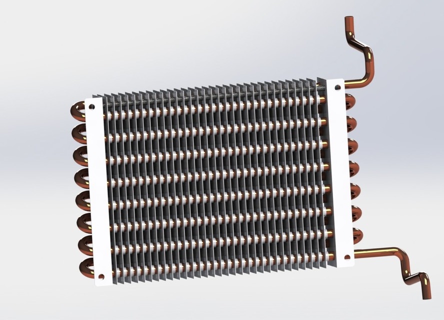
The heat recovery system in a fuel cell CHP plant is designed to capture the thermal energy produced during the electrochemical reactions in the fuel cell stack and convert it into useful heat for space heating, domestic hot water, or industrial processes. While the fuel cell generates electricity directly from chemical energy, the reaction also produces significant amounts of heat as a byproduct. Instead of being wasted, this heat can be efficiently recovered, which significantly increases the overall energy efficiency of the CHP plant. By combining electricity generation with heat utilization, the plant achieves total efficiencies that are often much higher than those of conventional separate heat and power systems.
The system typically includes heat exchangers, circulation pumps, and distribution piping to transfer the thermal energy from the fuel cell stack to the intended applications. In certain fuel cell types, such as solid oxide or molten carbonate, the operating temperatures are higher, allowing for higher-quality heat that can be used directly for industrial processes or for generating additional steam. In lower-temperature fuel cells, such as proton exchange membrane (PEM) types, the recovered heat is often used for space heating or hot water systems. Proper design and integration of the heat recovery system are essential to ensure maximum energy capture without interfering with the operating conditions of the fuel cell stack.
Thermal management is a critical aspect of heat recovery in fuel cell CHP plants. By maintaining optimal stack temperatures, the heat recovery system not only provides useful thermal energy but also helps protect the fuel cell components from overheating and ensures consistent electrical output. Circulation pumps and control valves regulate the flow of heat transfer fluids to maintain stable temperatures, while sensors monitor both the stack and the distribution system to prevent inefficiencies or safety issues. Heat recovery systems can also be coupled with storage tanks or buffer systems, allowing the plant to supply heat even during periods of low electrical demand.
Integration with building or industrial energy systems is another important function of the heat recovery system. It distributes the captured thermal energy to space heating, hot water, or process heating applications efficiently and safely. Advanced control systems monitor the heat demand and modulate the flow to ensure that energy is delivered exactly where and when it is needed, improving comfort, reducing energy waste, and maximizing overall system efficiency.
Overall, the heat recovery system is a key component of a fuel cell CHP plant, enabling the full utilization of energy produced by the electrochemical reactions. By capturing and distributing waste heat, it increases the plant’s total efficiency, reduces operational costs, and enhances the environmental benefits of fuel cell technology. This system allows the plant to provide both reliable electricity and useful heat, making fuel cell CHP solutions an effective and sustainable choice for commercial, industrial, and residential energy applications.
The heat recovery system in a fuel cell CHP plant plays a vital role in maximizing the overall energy efficiency of the system by capturing the thermal energy produced as a byproduct of the electrochemical reactions in the fuel cell stack. While the stack generates electricity directly from chemical energy, it also releases significant amounts of heat, which, if left unused, would represent wasted energy. The heat recovery system captures this thermal energy and transfers it to applications such as space heating, domestic hot water, or industrial process heating, allowing the plant to achieve total efficiencies far higher than conventional electricity-only generation systems.
Heat exchangers form the core of the heat recovery system, transferring heat from the fuel cell stack to a circulating fluid, typically water or a water-glycol mixture. Circulation pumps and control valves regulate the flow of this heat transfer fluid to maintain optimal temperatures and ensure that the recovered heat is delivered efficiently to the intended applications. In high-temperature fuel cells like solid oxide or molten carbonate types, the captured heat can be used for industrial processes or even for generating additional steam, while lower-temperature fuel cells, such as PEM units, primarily supply heat for space heating or hot water. Proper integration of the heat recovery system ensures that the fuel cell operates under stable conditions without overheating, maintaining consistent electrical output and prolonging the stack’s lifespan.
Thermal management is a key function of the heat recovery system, ensuring that the fuel cell stack operates within safe temperature ranges. Sensors continuously monitor stack temperatures and the distribution system, while control mechanisms adjust the flow of the heat transfer fluid to prevent inefficiencies or potential damage. In some installations, heat storage tanks or buffers are included to store excess thermal energy, enabling the plant to supply heat even during periods of low electrical demand or temporary fluctuations in thermal requirements. This ensures continuous and reliable delivery of both electricity and heat.
The integration of the heat recovery system with building or industrial energy systems allows for effective and controlled distribution of thermal energy. Advanced control systems monitor demand and modulate the delivery of heat to match the needs of the facility, reducing energy waste and improving overall operational efficiency. By capturing and utilizing this otherwise wasted thermal energy, the system not only increases total plant efficiency but also contributes to lower operational costs and reduced environmental impact.
In summary, the heat recovery system is an essential component of a fuel cell CHP plant, enabling the effective use of the thermal energy produced by the fuel cell stack. By transferring and managing this heat for practical applications, the system enhances overall energy efficiency, ensures reliable operation, and maximizes the economic and environmental benefits of combined heat and power generation. It allows the plant to provide a continuous supply of both electricity and useful heat, making fuel cell CHP technology a highly sustainable and efficient solution for commercial, industrial, and residential energy needs.
The heat recovery system in a fuel cell CHP plant is essential for capturing the thermal energy produced during the electrochemical reactions in the fuel cell stack and putting it to productive use. While the primary output of the stack is electricity, a significant amount of heat is generated as a byproduct. Instead of being wasted, this heat is transferred to a circulating fluid, typically water or a water-glycol mixture, and delivered to applications such as space heating, domestic hot water, or industrial process heating. By utilizing this otherwise wasted energy, the plant can achieve total efficiencies much higher than those of traditional electricity-only generation systems.
Heat exchangers are the core components of the heat recovery system, enabling efficient transfer of thermal energy from the fuel cell stack to the distribution network. Circulation pumps and control valves regulate the flow of the heat transfer fluid, maintaining optimal temperatures and ensuring that energy is delivered efficiently where it is needed. In high-temperature fuel cells like solid oxide or molten carbonate stacks, the recovered heat can even be used to produce additional steam for industrial processes, while lower-temperature systems, such as PEM fuel cells, typically supply heat for domestic or commercial heating applications. Properly designed heat recovery systems prevent overheating of the stack, ensuring stable electrical output and prolonging the operational life of the fuel cell.
Thermal management is a critical function of the heat recovery system. Sensors constantly monitor stack and fluid temperatures, and the control system adjusts the flow of heat to prevent inefficiencies or potential damage to the equipment. Many systems incorporate thermal storage or buffer tanks, allowing heat to be stored temporarily and supplied during periods of low demand or fluctuating load requirements. This ensures that both electricity and heat are available reliably and consistently, improving the overall performance and flexibility of the CHP plant.
Integration with the facility’s energy system is another key role of the heat recovery system. Advanced control algorithms monitor heat demand and modulate delivery to match building or industrial needs, reducing energy waste and maximizing operational efficiency. By recovering and utilizing the thermal energy generated by the fuel cell stack, the system reduces fuel consumption, lowers operational costs, and minimizes environmental impact. It ensures that the combined heat and power system operates at its highest potential, providing sustainable and efficient energy.
Overall, the heat recovery system is a vital component of a fuel cell CHP plant, enabling the effective use of thermal energy generated during electricity production. By capturing and distributing this heat for practical applications, it increases total energy efficiency, maintains stable operation, and enhances the economic and environmental benefits of fuel cell technology. Through proper design, monitoring, and integration, the heat recovery system ensures that the CHP plant delivers a continuous and reliable supply of both electricity and useful heat.
The heat recovery system in a fuel cell CHP plant is designed to capture the thermal energy produced as a byproduct of the electrochemical reactions within the fuel cell stack and make it available for practical use. While the fuel cell primarily generates electricity, a significant portion of energy is released in the form of heat. The heat recovery system transfers this thermal energy to a fluid, usually water or a water-glycol mixture, which is then circulated to supply space heating, domestic hot water, or industrial process heating. By utilizing this otherwise wasted heat, the CHP plant can achieve overall energy efficiencies that far exceed those of conventional electricity-only systems.
At the core of the heat recovery system are heat exchangers that efficiently transfer the thermal energy from the fuel cell stack to the distribution network. Circulation pumps and control valves regulate the flow of the heat transfer fluid, maintaining stable temperatures and ensuring that heat is delivered to the intended applications effectively. High-temperature fuel cells, such as solid oxide or molten carbonate types, produce heat at temperatures suitable for industrial processes or additional steam generation, while lower-temperature systems, like PEM fuel cells, supply heat primarily for commercial or residential heating. The heat recovery system is carefully designed to maintain optimal stack temperatures, protecting the fuel cell from overheating and ensuring consistent electricity production.
Thermal management is a crucial function of the system. Sensors continuously monitor the temperature of the stack and the heat transfer fluid, while the control system adjusts flow rates to prevent inefficiencies or equipment damage. Many heat recovery systems include thermal storage or buffer tanks, allowing excess heat to be stored and used later when demand increases or during periods of low electrical load. This ensures that both electricity and heat are supplied reliably and efficiently, enhancing the overall flexibility and performance of the CHP plant.
Integration with the building or industrial energy systems is essential for the effective use of recovered heat. Advanced control systems match heat delivery with real-time demand, reducing energy waste and maximizing system efficiency. By capturing and utilizing the thermal energy from the fuel cell, the plant reduces overall fuel consumption, lowers operational costs, and minimizes environmental impact. The heat recovery system enables the plant to operate as a true combined heat and power system, delivering both electricity and usable heat simultaneously.
In conclusion, the heat recovery system is a vital component of a fuel cell CHP plant, ensuring that the thermal energy generated during electricity production is effectively captured and utilized. It enhances total energy efficiency, protects the fuel cell stack, and provides a reliable source of heat for various applications. By optimizing the use of waste heat, the system maximizes economic and environmental benefits, making fuel cell CHP technology a highly efficient and sustainable solution for commercial, industrial, and residential energy needs.
Biomass and Waste-Fired CHP Plants
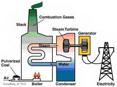
Biomass and waste-fired CHP plants are designed to generate both electricity and useful heat by utilizing organic and combustible waste materials as fuel. These plants convert the chemical energy stored in biomass, such as wood chips, agricultural residues, or specially grown energy crops, as well as municipal solid waste or industrial organic byproducts, into energy through combustion or gasification processes. By recovering both electricity and thermal energy, biomass and waste-fired CHP plants achieve much higher overall efficiencies than conventional power generation systems, while simultaneously providing a renewable or otherwise underutilized source of fuel.
The fuel handling system in these plants is critical for efficient operation. Biomass and waste fuels are often heterogeneous in size, moisture content, and calorific value, so they require preprocessing such as shredding, drying, or sorting before entering the combustion or gasification chamber. Conveyors, hoppers, and storage silos are used to ensure a continuous and regulated feed into the energy conversion system. Proper handling minimizes operational disruptions and allows for stable combustion or gasification, which is essential for maintaining both electrical output and heat generation.
The core of the plant is the boiler or gasifier, where the fuel undergoes controlled combustion or gasification. In combustion-based systems, the biomass or waste is burned at high temperatures to produce hot flue gases, which are used to generate steam in a boiler. The steam then drives a turbine connected to an electric generator. In gasification systems, the fuel is converted into a combustible gas mixture, known as syngas, which can be burned in a gas engine or turbine to produce electricity and heat. Advanced emission control systems are incorporated to remove pollutants such as particulate matter, nitrogen oxides, and dioxins, ensuring compliance with environmental regulations.
The steam turbine and electric generator convert the thermal energy of the steam or syngas into electricity. Steam turbines in larger biomass or waste CHP plants operate on the Rankine cycle, producing high-pressure steam that drives the turbine blades. In smaller plants or gasification systems, gas engines or gas turbines may be used, offering faster startup times and more flexible operation. The recovered heat from flue gases, turbine exhaust, or engine cooling systems is captured in heat exchangers and distributed for district heating, industrial processes, or domestic hot water, significantly improving overall plant efficiency.
Auxiliary systems play an important role in maintaining continuous and efficient operation. These include ash handling and disposal for combustion residues, flue gas cleaning systems, feedwater treatment, and cooling systems. Control and monitoring systems ensure stable operation, optimize fuel-to-energy conversion, and maintain safety by monitoring temperature, pressure, and emissions in real time. Modern biomass and waste CHP plants are often designed with automation that allows them to adjust to varying fuel characteristics and fluctuating energy demand, maximizing both electricity and heat output.
In summary, biomass and waste-fired CHP plants provide a sustainable and efficient method of generating electricity and heat from renewable or otherwise discarded fuels. By integrating fuel handling, combustion or gasification, electricity generation, heat recovery, and auxiliary systems, these plants deliver high overall energy efficiency while reducing reliance on fossil fuels and minimizing environmental impact. They serve as effective solutions for industrial facilities, municipal energy networks, and communities seeking to utilize locally available biomass or waste resources for clean and reliable combined heat and power generation.
The main parts of a biomass and waste-fired CHP plant include several integrated systems that work together to convert solid fuels into electricity and useful heat.
Fuel Handling and Storage Systems manage the reception, storage, and preprocessing of biomass or waste fuels. These systems typically include conveyors, hoppers, silos, shredders, and drying equipment to ensure consistent fuel quality, size, and moisture content before feeding it into the combustion or gasification chamber. Proper fuel handling is critical for maintaining stable and efficient energy conversion.
Combustion or Gasification Chamber is the core of the plant, where the biomass or waste fuel is either burned directly in a boiler or converted into syngas through gasification. In combustion systems, high-temperature flue gases are produced and transferred to a boiler to generate steam, while gasification systems produce syngas that can be used in gas engines or turbines. Both systems often include advanced controls to optimize combustion or gasification efficiency and minimize emissions.
Boiler / Steam Generation System converts the thermal energy from combustion or syngas burning into high-pressure steam. The steam is then directed to a steam turbine in larger plants, or the heat may be used directly in smaller or modular systems. Heat exchangers in the boiler capture as much energy as possible from the flue gases for steam production and sometimes for preheating incoming water or fuel.
Steam Turbine and Electric Generator convert the thermal energy of the steam into electricity. The turbine operates on the Rankine cycle, expanding high-pressure steam to rotate the blades, which drive the generator to produce electricity. In gasification systems, gas engines or small turbines may serve the same purpose, providing both electrical power and heat from engine cooling and exhaust.
Heat Recovery System captures waste heat from flue gases, steam condensation, or engine exhaust and distributes it for district heating, hot water, or industrial processes. This system significantly increases the overall efficiency of the plant and ensures effective utilization of all energy produced.
Flue Gas Cleaning and Emission Control Systems remove particulate matter, nitrogen oxides, dioxins, and other pollutants from exhaust gases before they are released into the atmosphere. Components often include electrostatic precipitators, bag filters, scrubbers, and catalytic converters to meet environmental regulations.
Ash Handling and Disposal System collects and processes the residual ash from fuel combustion or gasification. Mechanical conveyors, hoppers, and storage units manage bottom ash and fly ash, which may be disposed of or reused as a soil amendment or construction material, depending on quality.
Cooling and Condensate Systems manage the temperature of steam or hot water, condensing excess steam when necessary, and returning condensate to the boiler. This system ensures stable operation, protects equipment, and improves efficiency.
Control and Monitoring Systems oversee the operation of the plant, tracking parameters such as temperature, pressure, fuel flow, emissions, and electricity output. Advanced automation enables real-time adjustments, optimizing energy conversion, safety, and environmental performance.
Auxiliary Systems include pumps, fans, electrical transformers, backup power supplies, and safety systems that support continuous operation and reliability of the CHP plant.
These main parts work in unison to ensure that biomass and waste-fired CHP plants operate efficiently, safely, and sustainably, producing both electricity and heat from renewable or otherwise discarded fuel sources.
Fuel Handling and Storage Systems
Fuel handling and storage systems are a critical component of biomass and waste-fired CHP plants, as they ensure a continuous and consistent supply of fuel to the combustion or gasification system. Biomass and waste fuels often vary widely in size, moisture content, density, and energy content, so proper handling and preparation are essential for stable and efficient plant operation. The system begins with the reception of raw fuel, which may arrive as wood chips, pellets, agricultural residues, municipal solid waste, or industrial organic byproducts. Unloading equipment such as hoppers, tipping stations, or cranes ensures that fuel is safely and efficiently received from delivery vehicles.
Once received, fuel is typically stored in silos, bunkers, or storage yards designed to protect it from moisture, contamination, and degradation. Storage systems are often equipped with aeration, turning, or drying mechanisms to maintain uniform quality and prevent spoilage or spontaneous combustion, particularly in biomass with high moisture content. Preprocessing may be required, including shredding, grinding, screening, or drying, to produce fuel of consistent size and moisture content that is suitable for combustion or gasification. Proper fuel preparation improves combustion efficiency, reduces emissions, and protects downstream equipment from clogging or excessive wear.
Conveyors, feeders, and dosing systems transport the prepared fuel from storage to the combustion or gasification chamber. These systems are designed to deliver fuel at a controlled rate that matches the energy demand of the plant, ensuring stable temperature and pressure in the boiler or gasifier. Automated controls and sensors monitor fuel flow, level, and quality to prevent interruptions and optimize overall plant performance. Backup handling and feeding systems are often included to manage fuel variability or temporary blockages, ensuring continuous operation.
The design of fuel handling and storage systems also prioritizes safety and environmental protection. Dust extraction and ventilation systems reduce airborne particulate matter, while enclosed conveyors and storage units minimize fuel losses and fire hazards. Systems are typically constructed from durable materials to withstand abrasion from bulk solids and designed for easy maintenance to reduce downtime.
In summary, fuel handling and storage systems form the foundation of a biomass and waste-fired CHP plant. By ensuring a consistent, safe, and high-quality fuel supply, these systems directly influence combustion efficiency, emissions control, and overall plant reliability, making them indispensable for effective and sustainable combined heat and power generation.
Fuel handling and storage systems are essential for the efficient operation of biomass and waste-fired CHP plants, as they ensure a steady and reliable supply of fuel to the combustion or gasification system. Biomass and waste fuels are often heterogeneous, varying in size, moisture content, density, and energy value, which makes proper handling and preparation critical for stable plant performance. Raw fuel is typically delivered in bulk form, such as wood chips, pellets, agricultural residues, municipal solid waste, or industrial organic byproducts, and is received using hoppers, tipping stations, cranes, or other unloading equipment that safely manage the material.
Once received, the fuel is stored in silos, bunkers, or storage yards that protect it from moisture, contamination, and degradation. Storage systems may include aeration, turning, or drying mechanisms to maintain uniform fuel quality and prevent spoilage or self-heating, particularly for high-moisture biomass. Preprocessing steps such as shredding, grinding, screening, or drying are often required to produce fuel with consistent size and moisture content, which improves combustion or gasification efficiency, reduces emissions, and protects downstream equipment from wear or blockages.
Conveyors, feeders, and dosing systems transport the prepared fuel from storage to the boiler or gasifier at a controlled rate that matches the energy demand of the plant. Automated monitoring and control systems track fuel levels, flow rates, and quality, allowing the system to adjust feeding rates in real time to maintain stable temperature, pressure, and energy output. Backup handling and feeding mechanisms are typically included to manage variations in fuel quality or temporary interruptions in supply, ensuring uninterrupted operation.
Safety and environmental considerations are also critical in fuel handling and storage. Dust extraction and ventilation systems minimize airborne particulates, while enclosed conveyors and storage units reduce the risk of fire and prevent fuel losses. Equipment is constructed from durable materials to resist abrasion from bulk solids, and designs emphasize ease of maintenance to reduce downtime.
In essence, fuel handling and storage systems are the backbone of a biomass and waste-fired CHP plant. By ensuring a continuous, high-quality, and safely managed fuel supply, these systems directly influence the efficiency of combustion or gasification, the reliability of electricity and heat production, and the overall sustainability of the plant. Properly designed and maintained fuel handling systems are therefore critical for achieving the high operational performance and environmental benefits expected from modern CHP technology.
Fuel handling and storage systems are fundamental to the operation of biomass and waste-fired CHP plants, providing a continuous and controlled supply of fuel to the energy conversion system. Biomass and waste fuels are often irregular in size, moisture content, density, and calorific value, making proper handling and preparation critical for consistent and efficient plant performance. Upon arrival, fuels such as wood chips, pellets, agricultural residues, municipal solid waste, or industrial organic byproducts are unloaded using hoppers, tipping stations, or conveyor systems that safely manage bulk materials while minimizing spillage and dust generation.
Once received, the fuel is stored in silos, bunkers, or storage yards designed to protect it from moisture, contamination, and decomposition. Storage systems often incorporate mechanisms for aeration, turning, or drying to maintain uniform quality and prevent spontaneous combustion, especially in high-moisture biomass. Preprocessing is frequently required to standardize fuel size and moisture content, which may involve shredding, grinding, screening, or drying. This step ensures more efficient and stable combustion or gasification, reduces emissions, and protects downstream equipment from blockages or wear caused by inconsistent fuel characteristics.
Conveyors, feeders, and dosing mechanisms transport the prepared fuel from storage to the boiler or gasifier at a controlled rate aligned with the plant’s operational demand. Automated sensors and control systems continuously monitor fuel flow, levels, and quality, allowing real-time adjustments to maintain stable temperature, pressure, and energy output. Redundant or backup handling systems are often included to mitigate the impact of fuel variability or temporary interruptions, ensuring continuous operation and reliability of the CHP plant.
Safety and environmental considerations are integral to the design of fuel handling and storage systems. Dust extraction, ventilation, and enclosed transport systems reduce particulate emissions, minimize fuel losses, and lower the risk of fire. Equipment is constructed from abrasion-resistant materials to handle bulk solids, and the layout is designed for easy maintenance and accessibility, which helps minimize downtime and operational disruption.
Overall, fuel handling and storage systems form the backbone of biomass and waste-fired CHP plants. They ensure a steady, safe, and high-quality supply of fuel, which is critical for efficient combustion or gasification, stable electricity and heat production, and long-term operational reliability. By providing consistent fuel delivery and managing variability, these systems play a central role in maximizing plant efficiency, reducing emissions, and supporting sustainable energy generation.
Fuel handling and storage systems are a key component of biomass and waste-fired CHP plants, as they ensure a consistent and reliable supply of fuel to the combustion or gasification units. Biomass and waste fuels are inherently variable in size, moisture content, density, and energy value, which makes careful handling and preparation critical for stable and efficient operation. When the fuel is delivered to the plant, it is unloaded through hoppers, tipping stations, or conveyor systems, which are designed to manage large volumes of material safely while minimizing dust, spillage, and contamination.
Once received, fuels are stored in silos, bunkers, or storage yards that protect them from weather, moisture, and deterioration. Storage systems often include features such as aeration, turning mechanisms, or drying systems to maintain uniform fuel quality and prevent risks like spontaneous combustion, particularly in high-moisture biomass. Preprocessing of the fuel is usually necessary to achieve uniform size and moisture content. Shredding, grinding, screening, and drying processes help ensure that the fuel can be efficiently burned or gasified, improving energy conversion, reducing emissions, and protecting downstream equipment from blockages and wear.
Conveyors, feeders, and dosing equipment transport the prepared fuel from storage to the boiler or gasifier at a controlled and consistent rate. Automated monitoring systems track fuel flow, levels, and quality, adjusting feeding rates in real time to match the energy demand of the plant and maintain stable operation. Backup systems are often included to handle variations in fuel quality or temporary disruptions in supply, ensuring uninterrupted operation and reliability of the CHP plant.
Environmental and safety considerations are integral to the design of fuel handling and storage systems. Dust extraction, enclosed transport, and ventilation systems reduce airborne particulate matter, prevent fuel losses, and minimize fire hazards. Equipment is built from durable, abrasion-resistant materials and arranged for ease of maintenance, helping to reduce operational downtime and ensure smooth operation.
In essence, fuel handling and storage systems form the foundation of biomass and waste-fired CHP plants. By providing a steady, safe, and high-quality fuel supply, they directly influence combustion or gasification efficiency, emission control, and the reliability of electricity and heat production. Properly designed and managed fuel handling systems are essential to achieving high overall efficiency, operational stability, and the environmental benefits associated with combined heat and power generation from biomass and waste fuels.
Combustion or Gasification Chamber
The combustion or gasification chamber is the heart of a biomass and waste-fired CHP plant, where the chemical energy stored in the fuel is converted into thermal energy. In combustion-based systems, biomass or waste fuel is burned in a controlled environment at high temperatures, producing hot flue gases that transfer energy to a boiler for steam generation. In gasification systems, the fuel is partially oxidized under controlled conditions to produce a combustible gas mixture, or syngas, which can then be burned in a gas engine or turbine to generate electricity and heat. Both processes require precise control of temperature, airflow, and fuel feed to maximize efficiency and minimize emissions.
The design of the chamber is critical for effective energy conversion. It must accommodate varying fuel sizes, moisture content, and calorific values while ensuring complete combustion or gasification. Grate systems, fluidized beds, or fixed-bed designs are commonly used to support the fuel and enhance contact with oxygen or the gasifying agent. Proper residence time and uniform temperature distribution within the chamber are essential to ensure that the fuel is fully converted and to reduce the production of unburned residues or pollutants. High-temperature operation in the chamber also facilitates the thermal breakdown of complex organic compounds in waste, allowing for cleaner exhaust gases and higher energy recovery.
Air supply and combustion control systems play a crucial role in the operation of the chamber. Forced or induced draft fans regulate the flow of air or oxygen, maintaining the optimal stoichiometric ratio for complete fuel conversion. In gasification chambers, the supply of air, steam, or oxygen is carefully balanced to control the chemical reactions that produce syngas. Sensors and automated controls continuously monitor temperature, pressure, gas composition, and combustion efficiency, enabling real-time adjustments to fuel feed rates and airflow to maintain stable operation and high efficiency.
Heat recovery is integrated closely with the chamber to maximize energy utilization. Flue gases exiting the combustion chamber are directed to boilers or heat exchangers to produce steam or hot water for electricity generation and thermal applications. In gasification systems, the produced syngas can be cleaned and cooled before being combusted in engines or turbines, allowing for both electrical and thermal energy production. Proper insulation and refractory lining of the chamber are also essential to minimize heat losses and protect structural components from high-temperature degradation.
Environmental and operational considerations are central to the chamber design. Advanced emission control technologies, including catalytic converters, scrubbers, and particulate filters, are often incorporated to reduce pollutants such as nitrogen oxides, particulate matter, and dioxins. The chamber must also be designed for durability and ease of maintenance, as high temperatures and abrasive fuel materials can cause wear over time.
Overall, the combustion or gasification chamber is a critical component of biomass and waste-fired CHP plants. It transforms solid fuels into usable thermal and electrical energy efficiently and safely, while supporting emission control and heat recovery. The design, control, and integration of the chamber directly impact the overall performance, reliability, and environmental footprint of the CHP plant, making it a cornerstone of modern biomass and waste-to-energy systems.
The combustion or gasification chamber is the central unit of a biomass and waste-fired CHP plant, where the energy stored in organic or waste fuels is converted into heat and, subsequently, electricity. In a combustion system, the fuel is burned at high temperatures in a controlled environment, producing hot flue gases that transfer thermal energy to a boiler for steam generation. In contrast, a gasification system partially oxidizes the fuel under controlled conditions, producing a combustible gas mixture known as syngas, which can then be used in a gas engine or turbine to generate electricity and heat. Both methods rely on precise control of temperature, airflow, and fuel feed to achieve high energy efficiency and minimize emissions.
The chamber must be designed to accommodate variations in fuel type, size, moisture content, and energy value. Grate systems, fluidized beds, or fixed-bed designs are commonly used to support the fuel and optimize contact with air or oxygen. Adequate residence time and uniform temperature distribution are essential for complete conversion of fuel, reducing the formation of unburned residues or harmful pollutants. High operating temperatures also facilitate the breakdown of complex organic compounds in waste, improving energy recovery and ensuring cleaner exhaust gases.
Air supply and combustion control are critical to the operation of the chamber. Forced or induced draft fans regulate the airflow to maintain the optimal ratio of fuel to oxygen, ensuring efficient combustion. In gasification systems, the amount of air, steam, or oxygen introduced must be carefully balanced to control the chemical reactions that produce syngas. Advanced sensors and control systems continuously monitor temperature, pressure, and gas composition, allowing automatic adjustments to fuel feed and air supply for stable operation and maximum efficiency.
The chamber is closely integrated with heat recovery systems to ensure that the energy produced is effectively utilized. Flue gases from combustion are directed to boilers or heat exchangers, generating steam or hot water for electricity generation and thermal applications. In gasification setups, syngas is cooled and cleaned before combustion in engines or turbines, maximizing both electrical and thermal energy output. Refractory linings and insulation protect the chamber structure from high temperatures and minimize heat losses.
Environmental and operational considerations are paramount in chamber design. Emission control technologies such as particulate filters, scrubbers, and catalytic converters reduce pollutants like nitrogen oxides, particulate matter, and dioxins. The chamber is also designed for durability and maintainability, as high temperatures and abrasive fuel materials can cause wear over time.
Overall, the combustion or gasification chamber is a pivotal component of biomass and waste-fired CHP plants. It efficiently converts solid fuels into thermal and electrical energy while supporting heat recovery and emission control. Its design, operation, and integration with other plant systems directly determine the overall efficiency, reliability, and environmental performance of the CHP plant, making it essential for effective biomass and waste-to-energy generation.
The combustion or gasification chamber is the central element in a biomass and waste-fired CHP plant, responsible for converting the chemical energy of solid fuels into thermal energy that can be further used for electricity generation or heating. In combustion systems, biomass or waste is burned at high temperatures in a carefully controlled environment, producing hot flue gases that are directed to a boiler to generate steam. In gasification systems, the fuel undergoes partial oxidation under controlled conditions, producing syngas—a mixture of carbon monoxide, hydrogen, and other combustible gases—which can be burned in a gas engine or turbine to produce electricity and heat simultaneously. Both approaches require precise management of temperature, fuel feed, and airflow to ensure maximum energy efficiency and minimize emissions.
The design of the chamber must accommodate a wide range of fuel types and qualities, including variations in moisture content, particle size, and calorific value. Common configurations include grate systems, fluidized beds, and fixed-bed designs, all intended to optimize fuel contact with oxygen or the gasifying agent. Adequate residence time and even temperature distribution within the chamber are crucial to ensure complete fuel conversion, reduce unburned residues, and minimize the formation of pollutants. High operating temperatures also facilitate the breakdown of complex organic compounds in waste, enabling cleaner exhaust gases and improved energy recovery.
Air supply and combustion control systems play a key role in maintaining stable chamber operation. Forced or induced draft fans regulate the airflow to achieve the proper fuel-to-oxygen ratio, while in gasification chambers, the introduction of air, steam, or oxygen is carefully balanced to optimize syngas production. Sensors and automated control systems continuously monitor temperature, pressure, and gas composition, allowing real-time adjustments to fuel feed and airflow to maintain efficiency and prevent operational disturbances.
Heat recovery is closely integrated with the chamber to ensure that as much energy as possible is captured and used. Flue gases from combustion are directed to heat exchangers or boilers, generating steam or hot water for electricity generation and thermal applications. In gasification systems, syngas is cleaned and cooled before combustion in engines or turbines, maximizing both electrical and thermal energy output. Refractory linings and insulation protect the chamber structure from extreme temperatures and reduce heat losses.
Environmental and operational considerations are essential in the chamber’s design. Advanced emission control technologies, including filters, scrubbers, and catalytic converters, reduce nitrogen oxides, particulate matter, and other pollutants. The chamber is also built to withstand high temperatures and abrasive fuel materials, ensuring durability and reducing maintenance requirements.
Overall, the combustion or gasification chamber is the heart of a biomass and waste-fired CHP plant, transforming solid fuels into usable heat and electricity while supporting heat recovery and emission control. Its proper design, operation, and integration with other plant systems directly influence overall efficiency, reliability, and environmental performance, making it a cornerstone of modern biomass and waste-to-energy technology.
The combustion or gasification chamber is the heart of a biomass and waste-fired CHP plant, where the energy stored in the fuel is converted into usable heat and electricity. In a combustion system, solid biomass or waste is burned at high temperatures in a controlled environment, generating hot flue gases that transfer energy to a boiler for steam production. In a gasification system, the fuel undergoes partial oxidation under controlled conditions, producing syngas—a mixture of combustible gases such as hydrogen and carbon monoxide—that can be burned in a gas engine or turbine to generate both electricity and heat. Achieving optimal efficiency in either system requires careful management of fuel feed, airflow, and temperature.
The chamber must accommodate a variety of fuel types, sizes, and moisture contents while ensuring complete combustion or gasification. Common designs include grate-fired, fluidized bed, and fixed-bed systems, each tailored to promote uniform temperature distribution and proper residence time for the fuel. Uniform temperatures and adequate residence time are critical to maximize energy conversion, minimize unburned residues, and reduce the production of pollutants. High temperatures in the chamber also facilitate the thermal breakdown of complex organic compounds in waste, contributing to cleaner exhaust gases and higher energy recovery.
Air supply and combustion control are essential to maintaining stable operation. Draft fans regulate the flow of air or oxygen to ensure proper stoichiometry for complete fuel conversion, while in gasification chambers, the supply of air, steam, or oxygen must be balanced to optimize syngas production. Modern systems are equipped with sensors and automated controls that continuously monitor temperature, pressure, and gas composition, adjusting fuel feed and airflow in real time to maintain efficiency and prevent operational disruptions.
The chamber is closely integrated with heat recovery systems to maximize energy utilization. Flue gases from combustion are directed to boilers or heat exchangers, producing steam or hot water for electricity generation and thermal applications. In gasification systems, syngas is cleaned and cooled before combustion in engines or turbines, allowing for efficient electrical and thermal energy production. Refractory linings and insulation are used to protect the chamber structure from high temperatures and to reduce heat losses, improving overall efficiency.
Environmental and operational considerations are also key to chamber design. Advanced emission control technologies, including particulate filters, scrubbers, and catalytic converters, help reduce nitrogen oxides, particulate matter, and dioxins. Chambers are built to withstand high temperatures and abrasive fuel materials, ensuring durability and facilitating maintenance.
Overall, the combustion or gasification chamber is the most critical component of a biomass and waste-fired CHP plant. It transforms solid fuels into thermal and electrical energy, supports heat recovery, and enables emission control. Its design, operation, and integration with other plant systems directly affect the efficiency, reliability, and environmental performance of the CHP plant, making it indispensable for modern biomass and waste-to-energy applications.
Boiler / Steam Generation System
The boiler or steam generation system in a biomass and waste-fired CHP plant is responsible for converting the thermal energy produced in the combustion or gasification chamber into high-pressure steam, which can then be used to drive a steam turbine for electricity generation or supplied directly for heating applications. The boiler is designed to capture as much heat as possible from the hot flue gases produced during fuel conversion, ensuring maximum energy utilization and high overall plant efficiency. Water circulating within the boiler absorbs the heat, transforming into steam that reaches the required pressure and temperature for downstream processes.
The design of the boiler is critical to accommodate the variability of biomass and waste fuels, which can differ significantly in moisture content, particle size, and calorific value. Fluidized bed boilers, grate-fired boilers, and circulating fluidized bed designs are commonly used in these plants, each offering advantages in fuel flexibility, combustion efficiency, and emission control. Heat transfer surfaces within the boiler, such as water walls, superheaters, and economizers, are optimized to maximize energy capture while minimizing the temperature of flue gases leaving the system.
Feedwater treatment and circulation are integral to boiler operation. Water quality must be carefully managed to prevent scaling, corrosion, and fouling of heat transfer surfaces, which could reduce efficiency and increase maintenance requirements. Pumps circulate the feedwater through the boiler, maintaining proper flow rates to ensure uniform steam production and avoid localized overheating. Safety systems, including pressure relief valves and temperature monitoring, protect the boiler and the overall plant from overpressure or thermal stress.
The boiler is closely integrated with heat recovery and emission control systems. Flue gases are often directed through economizers and air preheaters to extract additional heat before passing through dust collectors, scrubbers, or catalytic converters to reduce pollutants. This integration allows the plant to meet environmental regulations while maximizing the use of available energy. In gasification-based plants, syngas combustion may occur in a dedicated boiler or a combined heat exchanger system, providing both steam and hot water for CHP applications.
Overall, the boiler or steam generation system is a core component of a biomass and waste-fired CHP plant, enabling the conversion of thermal energy into steam for electricity and heat production. Its design and operation are crucial for maximizing efficiency, ensuring reliable plant performance, and supporting sustainable energy generation. By effectively capturing heat from the combustion or gasification process and managing steam production, the boiler system ensures that the CHP plant delivers both electrical and thermal energy in a safe, efficient, and environmentally responsible manner.
The boiler or steam generation system in a biomass and waste-fired CHP plant serves as the link between the combustion or gasification process and the production of usable energy. Its primary function is to convert the thermal energy released from burning biomass or waste into high-pressure steam, which can then be used to drive a steam turbine for electricity generation or supplied for heating applications. By capturing as much heat as possible from the hot flue gases, the boiler maximizes overall energy efficiency and ensures that both electricity and heat are delivered effectively.
Boilers in these plants must be designed to handle the variability of biomass and waste fuels, which often differ in moisture content, particle size, and calorific value. Common configurations include grate-fired boilers, fluidized bed boilers, and circulating fluidized bed designs. Each type is chosen based on fuel characteristics, desired efficiency, and emission control requirements. Heat transfer surfaces within the boiler, including water walls, superheaters, and economizers, are carefully arranged to optimize the absorption of heat from the flue gases while minimizing heat losses. This ensures that the maximum amount of energy from the fuel is converted into steam.
Proper management of feedwater is crucial for reliable boiler operation. Water must be treated to prevent scaling, corrosion, or fouling of heat transfer surfaces, which can reduce efficiency and increase maintenance needs. Pumps circulate the water through the boiler, maintaining a consistent flow to produce uniform steam output and prevent localized overheating. Safety systems, such as pressure relief valves, temperature sensors, and automated shutdown mechanisms, protect the boiler and the entire plant from overpressure or thermal stress.
The boiler is closely integrated with heat recovery and emission control systems. Flue gases are often passed through economizers and air preheaters to extract additional heat before being treated in particulate filters, scrubbers, or catalytic converters to reduce pollutants. In gasification-based plants, the syngas produced may be combusted in the boiler or a combined heat exchanger system, providing both steam and hot water for CHP applications. This integration ensures that energy is used efficiently and environmental regulations are met.
Overall, the boiler or steam generation system is a fundamental component of biomass and waste-fired CHP plants. It converts the thermal energy of the fuel into high-pressure steam for electricity and heating, supporting the combined heat and power objectives of the plant. Proper design, water management, and integration with emission controls and heat recovery systems are essential for maximizing efficiency, reliability, and sustainability, making the boiler system indispensable for modern biomass and waste-to-energy operations.
The boiler or steam generation system is a vital component of a biomass and waste-fired CHP plant, serving as the primary mechanism for converting thermal energy from fuel into steam for electricity and heat production. As biomass or waste fuels are burned in the combustion chamber or partially oxidized in a gasifier, they release significant amounts of thermal energy. The boiler captures this heat through water-filled tubes, generating high-pressure steam that can drive a steam turbine or be used directly for industrial processes or district heating. Efficient heat transfer and minimal energy loss are critical to achieving high overall plant efficiency.
Boilers in biomass and waste CHP plants are specifically designed to accommodate the variable properties of these fuels, which may include differences in particle size, moisture content, and energy density. Common designs include grate-fired systems, fluidized bed boilers, and circulating fluidized bed boilers, each chosen based on fuel characteristics and operational requirements. Heat transfer surfaces, such as water walls, superheaters, and economizers, are strategically arranged to maximize heat absorption from the flue gases, while also preheating feedwater to improve efficiency. Uniform steam production depends on proper flow distribution and consistent temperature maintenance throughout the boiler.
Feedwater management and circulation are essential for reliable boiler operation. The water must be treated to prevent scaling, corrosion, or fouling, which can impair heat transfer and damage the boiler. Pumps ensure continuous circulation of feedwater, maintaining stable steam production and preventing localized overheating. Safety systems, including pressure relief valves, temperature monitors, and automatic shutdown mechanisms, protect the boiler and plant equipment from excessive pressure or thermal stress, ensuring safe operation at all times.
The boiler is closely integrated with heat recovery and emission control systems to maximize energy utilization and reduce environmental impact. Flue gases are often passed through economizers or air preheaters to extract additional heat before being cleaned by particulate filters, scrubbers, or catalytic converters to remove pollutants such as nitrogen oxides, dioxins, and particulate matter. In gasification-based plants, the syngas may be burned in the boiler or a combined heat exchanger, producing both steam and hot water for CHP applications, ensuring efficient utilization of all energy produced from the fuel.
In conclusion, the boiler or steam generation system is central to the operation of biomass and waste-fired CHP plants. It transforms the thermal energy of the fuel into high-pressure steam for electricity generation and heat supply, while supporting energy efficiency and environmental compliance. Proper design, water management, heat integration, and safety measures are essential for maximizing the performance, reliability, and sustainability of the CHP plant, making the boiler system indispensable for modern biomass and waste-to-energy technology.
The boiler or steam generation system in a biomass and waste-fired CHP plant is the component that transforms the thermal energy released from fuel into high-pressure steam for electricity production and heating. As fuel is combusted or gasified, it generates hot flue gases, and the boiler captures this heat to convert water into steam. This steam can then be directed to a steam turbine to generate electricity or used directly in district heating, industrial processes, or other thermal applications. Efficient heat capture and conversion are essential to ensure high overall plant efficiency and to make the most of the energy contained in the fuel.
Designing a boiler for biomass or waste fuels requires consideration of the variability in fuel size, moisture content, density, and calorific value. Grate-fired boilers, fluidized bed systems, and circulating fluidized bed boilers are commonly employed, with each configuration chosen based on fuel characteristics, combustion efficiency, and emission requirements. Heat transfer surfaces such as water walls, superheaters, and economizers are carefully arranged to maximize thermal energy absorption while preheating feedwater, reducing heat losses, and maintaining uniform steam quality. Proper flow distribution within the boiler ensures consistent steam production and prevents hot spots or localized overheating.
Feedwater treatment and circulation are vital to maintaining the longevity and efficiency of the boiler. Impurities in the water can lead to scaling, corrosion, or fouling of heat transfer surfaces, reducing efficiency and increasing maintenance needs. Pumps circulate treated water throughout the boiler system, ensuring stable steam output and protecting the equipment from thermal stress. Safety systems, including pressure relief valves, temperature sensors, and automatic shutdown mechanisms, safeguard the boiler and the overall plant from overpressure and unsafe operating conditions.
Heat recovery and emission control systems are closely integrated with the boiler to maximize energy utilization and minimize environmental impact. Flue gases are passed through economizers or air preheaters to extract additional heat before being treated with particulate filters, scrubbers, or catalytic converters to remove pollutants such as nitrogen oxides, particulate matter, and dioxins. In gasification systems, syngas is burned within the boiler or a combined heat exchanger, producing steam and hot water for CHP applications and ensuring that energy from the fuel is fully utilized.
In summary, the boiler or steam generation system is a core component of biomass and waste-fired CHP plants. It converts thermal energy from fuel into high-pressure steam for electricity and heat, while supporting emission control, heat recovery, and overall plant efficiency. Proper design, water management, integration with heat recovery systems, and safety measures are crucial for reliable, efficient, and environmentally responsible operation, making the boiler system indispensable for modern biomass and waste-to-energy CHP technology.
Steam Turbine and Electric Generator
The steam turbine and electric generator form the central power conversion system in a biomass and waste-fired CHP plant, transforming thermal energy from steam into mechanical and then electrical energy. High-pressure steam produced in the boiler or heat recovery system enters the steam turbine, where it expands through a series of blades, causing the turbine shaft to rotate. This mechanical rotation is then transferred directly to an electric generator, producing electricity for the grid, industrial facilities, or on-site consumption. The efficiency of this conversion process depends on the design of the turbine, the pressure and temperature of the steam, and the matching of the turbine with the generator and overall plant operating conditions.
Steam turbines in biomass and waste-fired CHP plants are typically designed to handle variable load conditions and fluctuating steam quality, as the characteristics of biomass and waste fuels can change over time. The turbine consists of multiple stages with blades and nozzles that gradually extract energy from the expanding steam, converting it into rotational motion. High-efficiency designs may include reheat or regenerative cycles, where steam is partially expanded, reheated, and sent through additional turbine stages to improve energy extraction. This ensures that the maximum amount of thermal energy from the steam is converted into useful mechanical energy.
The electric generator is directly coupled to the turbine shaft and converts rotational energy into electrical energy through electromagnetic induction. Depending on the plant size, generators can vary from smaller units for local applications to large industrial machines connected to the grid. Modern generators are designed for high reliability, efficiency, and stable voltage output. They are often equipped with monitoring systems to track temperature, vibration, and electrical parameters, ensuring safe and continuous operation.
Integration of the turbine and generator with the plant’s heat and steam distribution system allows for flexible operation in combined heat and power mode. Some of the steam can be extracted at intermediate pressures for district heating or industrial processes while the remainder continues through the turbine to maximize electricity generation. This extraction process requires precise control to balance electricity output with thermal energy delivery, optimizing overall plant efficiency.
Maintenance and operational considerations are essential for reliable performance. Turbine blades and casings are designed to withstand high temperatures, pressure fluctuations, and potential impurities in the steam from biomass or waste fuels. Regular inspection, lubrication, and monitoring of the generator and turbine components prevent wear and ensure continuous, efficient operation.
Overall, the steam turbine and electric generator are pivotal in converting thermal energy into electricity in biomass and waste-fired CHP plants. Their design, integration with the steam system, and operational management directly influence the efficiency, reliability, and flexibility of the plant, allowing it to provide both electrical power and heat in a sustainable and efficient manner.
The steam turbine and electric generator are the core components in a biomass and waste-fired CHP plant, responsible for converting the thermal energy of steam into mechanical rotation and then into electricity. High-pressure steam produced in the boiler or heat recovery system enters the turbine, where it expands across a series of blades, causing the turbine shaft to spin. This rotational energy is transferred directly to the electric generator, which converts it into electrical energy for on-site use, industrial processes, or grid supply. The efficiency of this process is influenced by the design of the turbine, the pressure and temperature of the steam, and the integration of the turbine and generator with the overall plant system.
Steam turbines in biomass and waste CHP plants must accommodate variable steam conditions, as fluctuations in fuel type, moisture content, and calorific value can affect steam pressure and temperature. Multi-stage turbines are often employed, where steam passes through a series of high-pressure, intermediate-pressure, and low-pressure stages, extracting maximum energy from the expanding steam. Advanced designs may incorporate reheat and regenerative cycles to improve energy recovery, where partially expanded steam is reheated and passed through additional stages before final condensation. This enhances overall plant efficiency and ensures that more of the fuel’s energy is converted into useful work.
The electric generator, directly coupled to the turbine shaft, converts mechanical rotation into electrical power through electromagnetic induction. Generators range in size depending on plant capacity, from smaller units for local applications to large machines supplying electricity to the grid. Modern generators are designed for high efficiency and reliable operation, with monitoring systems that track temperature, vibration, and electrical parameters to detect potential issues early and ensure continuous operation.
The integration of the turbine and generator with the plant’s steam distribution system allows for flexible CHP operation. Steam can be extracted at intermediate pressures to provide heating for district networks or industrial processes while the remaining steam continues through the turbine for electricity generation. This controlled extraction balances the simultaneous production of heat and power, optimizing plant performance and overall energy utilization.
Operational reliability and maintenance are key considerations for the turbine and generator. Turbine blades and casings must withstand high temperatures, pressure variations, and potential contaminants present in steam from biomass or waste fuels. Routine inspections, lubrication, and monitoring of electrical and mechanical components ensure long-term performance, prevent wear, and minimize unplanned downtime.
Overall, the steam turbine and electric generator are fundamental to the energy conversion process in biomass and waste-fired CHP plants. Their efficient design, proper integration with the steam and heat distribution system, and reliable operation are critical for maximizing electricity generation while supporting heat delivery, making them central to the plant’s performance, sustainability, and economic viability.
The steam turbine and electric generator are the central components in a biomass and waste-fired CHP plant, converting the thermal energy from steam into mechanical motion and subsequently into electricity. Steam produced in the boiler or heat recovery system enters the turbine at high pressure and temperature, causing the rotor to spin as it passes through multiple stages of blades. This rotational energy drives the generator, which produces electricity for on-site consumption, industrial processes, or supply to the power grid. The efficiency of this conversion depends on factors such as steam conditions, turbine design, and how well the turbine and generator are integrated with the plant’s overall system.
Steam turbines used in biomass and waste CHP plants are designed to accommodate variable fuel characteristics and fluctuating steam conditions. Multi-stage turbines are common, with high-pressure, intermediate-pressure, and low-pressure stages to extract maximum energy from the expanding steam. Advanced configurations often include reheat and regenerative cycles, where partially expanded steam is reheated and passed through additional turbine stages to increase energy extraction. These features improve overall plant efficiency and allow more of the energy in the fuel to be converted into usable electricity.
The electric generator is directly connected to the turbine shaft, converting the mechanical rotation into electrical energy through electromagnetic induction. Depending on the plant’s scale, generators can range from smaller units for local heat and power applications to large machines supplying electricity to the grid. Modern generators are engineered for reliability and efficiency, and they are equipped with monitoring systems that track temperature, vibration, and electrical output to ensure stable operation and prevent failures.
Integration of the turbine and generator with the steam distribution system enables combined heat and power operation. Steam can be extracted at intermediate pressures for heating or industrial use, while the remaining steam continues through the turbine to maximize electricity generation. This process requires precise control to maintain a balance between electrical output and thermal energy delivery, ensuring that the plant operates efficiently under varying demand conditions.
Maintenance and operational reliability are critical for these systems. Turbine blades and casings are designed to withstand high temperatures, pressure fluctuations, and impurities in steam derived from biomass or waste fuels. Routine inspections, lubrication, and continuous monitoring of both mechanical and electrical components are essential to prevent wear, reduce downtime, and ensure long-term efficient operation.
Overall, the steam turbine and electric generator are essential to biomass and waste-fired CHP plants, transforming steam into electricity while supporting heat recovery. Their proper design, integration with the plant’s steam and heat systems, and reliable operation directly affect the efficiency, performance, and sustainability of the plant, making them central to modern biomass and waste-to-energy technology.
The steam turbine and electric generator are the pivotal elements in a biomass and waste-fired CHP plant, responsible for converting the thermal energy contained in steam into mechanical rotation and subsequently into electrical power. High-pressure, high-temperature steam produced in the boiler or heat recovery system enters the turbine, expanding through a series of blades and causing the rotor to spin. This mechanical motion is directly transferred to the electric generator, producing electricity that can be supplied to the grid, used in industrial processes, or distributed for district heating. The efficiency of this conversion depends on the turbine design, the pressure and temperature of the steam, and the precise coordination between the turbine and generator with the rest of the plant’s systems.
Steam turbines in these plants must handle the variable properties of biomass and waste fuels, which can result in fluctuations in steam quality and pressure. Multi-stage turbine designs are commonly employed, with high-pressure, intermediate-pressure, and low-pressure stages to extract the maximum energy from the expanding steam. Advanced systems may include reheat or regenerative cycles, where partially expanded steam is reheated and sent through additional turbine stages to improve energy conversion efficiency. These design strategies ensure that more of the energy from the fuel is captured and converted into useful electrical and mechanical output.
The electric generator, coupled directly to the turbine shaft, converts the mechanical rotation into electrical energy through electromagnetic induction. Generator size and capacity vary according to the plant’s requirements, ranging from smaller units for local applications to large industrial generators connected to the grid. Modern generators are engineered for high efficiency and reliability, equipped with monitoring systems to track temperature, vibration, and electrical parameters, allowing early detection of potential issues and ensuring continuous operation.
The integration of the turbine and generator with the plant’s steam distribution system enables flexible operation in combined heat and power mode. Steam can be extracted at intermediate pressures for district heating or industrial applications while the remaining steam continues through the turbine to maximize electricity production. This controlled extraction allows the plant to balance electricity generation with thermal energy delivery, optimizing overall efficiency and energy utilization.
Operational reliability and maintenance are critical for long-term performance. Turbine blades and casings are built to withstand high temperatures, pressure variations, and potential impurities in steam derived from biomass or waste fuels. Regular inspection, lubrication, and monitoring of both turbine and generator components are necessary to prevent wear, reduce downtime, and maintain efficient operation over time.
Overall, the steam turbine and electric generator are central to the energy conversion process in biomass and waste-fired CHP plants. Their design, integration, and reliable operation determine the plant’s efficiency, flexibility, and ability to provide sustainable electricity and heat, making them indispensable components in modern biomass and waste-to-energy systems.
Heat Recovery System
The heat recovery system in a biomass and waste-fired CHP plant plays a crucial role in maximizing energy efficiency by capturing and utilizing thermal energy that would otherwise be lost. After fuel is combusted or gasified, flue gases or hot syngas exit the primary energy conversion system carrying a significant amount of residual heat. The heat recovery system captures this energy and transfers it to water or steam, which can then be used to produce electricity via a steam turbine or supplied as thermal energy for district heating, industrial processes, or on-site consumption. By efficiently utilizing waste heat, the system significantly improves the overall performance and energy yield of the plant.
Heat recovery systems are carefully designed to accommodate the variable characteristics of biomass and waste fuels, which can lead to fluctuations in flue gas temperature, composition, and flow rate. Economizers, air preheaters, and heat exchangers are commonly used to extract the maximum amount of energy from these gases. The captured heat is often used to preheat boiler feedwater, generate steam for turbines, or produce hot water for heating networks. Proper design ensures that heat transfer surfaces are optimized to prevent fouling, scaling, or corrosion, which are common challenges when dealing with the byproducts of biomass and waste combustion.
The system often includes advanced monitoring and control mechanisms to regulate heat recovery and maintain stable operation. Sensors track temperature, pressure, and flow rates, allowing automated adjustments to optimize energy extraction and ensure that downstream processes receive steam or hot water at the correct temperature and pressure. This real-time control is essential for maintaining plant efficiency and preventing thermal stress or equipment damage.
Integration with emission control technologies is another key aspect of the heat recovery system. Flue gases passing through the heat recovery units are often subsequently treated using particulate filters, scrubbers, or catalytic converters to reduce pollutants such as nitrogen oxides, dioxins, and particulate matter. This ensures that energy is recovered without compromising environmental compliance, making the system both efficient and sustainable.
Overall, the heat recovery system is vital for enhancing the efficiency and sustainability of biomass and waste-fired CHP plants. By capturing residual heat from flue gases or syngas and converting it into useful thermal or mechanical energy, the system maximizes fuel utilization, reduces waste, and supports the combined production of electricity and heat. Its design, integration, and operational management directly influence the plant’s overall performance, reliability, and environmental impact, making it an indispensable component of modern CHP technology.
The heat recovery system in a biomass and waste-fired CHP plant is essential for improving overall efficiency by capturing thermal energy from flue gases or syngas that would otherwise be lost. After combustion or gasification, these hot gases contain a significant amount of residual energy, which the heat recovery system transfers to water or steam for use in electricity generation or for supplying heat to district networks and industrial processes. By effectively utilizing this otherwise wasted energy, the system ensures that the plant extracts the maximum possible energy from the fuel, increasing both efficiency and sustainability.
Designing a heat recovery system for biomass and waste CHP plants requires accommodating the variability in fuel type, moisture content, and calorific value, which can affect flue gas temperature and composition. Common components include economizers, air preheaters, and heat exchangers, all designed to maximize heat transfer while minimizing fouling, scaling, and corrosion. Heat recovered from the flue gases is often used to preheat boiler feedwater, generate steam for turbines, or provide hot water for heating applications. Optimizing heat transfer surfaces and flow paths ensures consistent performance and prevents operational issues that could reduce efficiency or damage equipment.
Advanced monitoring and control are integral to the operation of the heat recovery system. Temperature, pressure, and flow sensors provide real-time data, enabling automated adjustments to maintain optimal heat recovery and deliver steam or hot water at the required parameters. This control ensures stable operation, protects downstream equipment, and maximizes energy extraction from the residual heat.
Integration with emission control technologies is another critical aspect. Flue gases that pass through heat recovery units are subsequently treated using particulate filters, scrubbers, or catalytic converters to remove pollutants such as nitrogen oxides, dioxins, and particulate matter. This approach allows the plant to recover energy while meeting environmental regulations, ensuring that heat recovery contributes to both efficiency and sustainability.
In summary, the heat recovery system is a vital component of biomass and waste-fired CHP plants, capturing residual thermal energy to produce additional electricity or useful heat. Its proper design, operation, and integration with the plant’s steam generation, electricity production, and emission control systems significantly enhance overall efficiency, reliability, and environmental performance, making it a cornerstone of modern combined heat and power technology.
The heat recovery system in a biomass and waste-fired CHP plant is a key element in maximizing the overall energy efficiency of the facility. After fuel is combusted or gasified, flue gases or syngas exit the main conversion system carrying substantial amounts of thermal energy. Instead of being released into the atmosphere, this residual heat is captured by the heat recovery system and transferred to water or steam, which can then be used to drive turbines for electricity generation or supplied directly as thermal energy for industrial applications or district heating. By utilizing this otherwise wasted heat, the plant can achieve significantly higher overall efficiency and reduce fuel consumption.
Designing a heat recovery system for biomass and waste CHP plants requires careful consideration of the variability of the fuels. Biomass and waste often have inconsistent moisture content, particle sizes, and calorific values, which can affect the temperature, flow, and composition of flue gases. The system commonly includes economizers, air preheaters, and other heat exchangers designed to extract as much thermal energy as possible. Heat recovered can preheat boiler feedwater, produce steam for turbines, or generate hot water for heating networks. Attention to design details, such as heat transfer surface area and flow paths, is crucial to prevent scaling, fouling, or corrosion, which could impair efficiency or require frequent maintenance.
The operation of the heat recovery system relies on sophisticated monitoring and control. Sensors measure temperature, pressure, and flow rates, allowing the system to adjust in real time to fluctuations in fuel characteristics or load demand. Automated control ensures that the recovered heat is delivered at the proper temperature and pressure, protects downstream equipment, and maintains stable operation throughout the plant. This dynamic management is essential for maintaining consistent energy output and maximizing the benefits of heat recovery.
Integration with emission control is another vital aspect of the heat recovery system. After passing through heat exchangers, flue gases are typically treated using particulate filters, scrubbers, or catalytic converters to remove pollutants such as nitrogen oxides, dioxins, and particulate matter. This ensures that the plant can recover heat efficiently while maintaining compliance with environmental standards. The combination of heat recovery and emission control enables the plant to operate sustainably and minimizes its environmental footprint.
Overall, the heat recovery system is indispensable for biomass and waste-fired CHP plants, capturing residual thermal energy from flue gases or syngas and converting it into useful electricity or heat. Its design, integration, and operation directly influence the plant’s efficiency, reliability, and environmental performance. By effectively utilizing energy that would otherwise be lost, the heat recovery system enhances the economic and ecological viability of combined heat and power operations, making it a cornerstone of modern biomass and waste-to-energy technology.
The heat recovery system in a biomass and waste-fired CHP plant plays a fundamental role in optimizing energy utilization by capturing thermal energy that would otherwise escape with flue gases or syngas. As biomass or waste fuel is combusted or gasified, it produces hot gases containing significant amounts of residual heat. The heat recovery system intercepts this energy, transferring it to water or steam that can be used to generate electricity through a steam turbine or supplied as thermal energy for district heating, industrial processes, or on-site applications. By recovering this otherwise wasted energy, the plant maximizes fuel efficiency and overall energy output.
Designing an effective heat recovery system requires accounting for the variable nature of biomass and waste fuels, which can cause fluctuations in flue gas temperature, composition, and flow rates. Components such as economizers, air preheaters, and heat exchangers are strategically implemented to capture as much thermal energy as possible. Recovered heat is often used to preheat boiler feedwater, generate steam for turbines, or provide hot water for heating networks. Proper design ensures optimal heat transfer, minimizes losses, and reduces the risk of fouling, scaling, or corrosion that can occur due to impurities in the fuel.
The operation of the heat recovery system relies on continuous monitoring and advanced control mechanisms. Sensors track temperature, pressure, and flow rates, allowing automated adjustments to maintain efficient heat recovery and ensure that steam or hot water is delivered at the appropriate conditions. Real-time control maintains stability in plant operation, protects downstream equipment from thermal stress, and maximizes the conversion of residual heat into useful energy.
Integration with emission control technologies is also a critical aspect of the system. After passing through the heat recovery units, flue gases are typically treated using particulate filters, scrubbers, or catalytic converters to remove pollutants such as nitrogen oxides, particulate matter, and dioxins. This combination of heat recovery and emissions management ensures that the plant operates efficiently while meeting strict environmental regulations, minimizing its ecological impact.
In conclusion, the heat recovery system is essential for enhancing the efficiency and sustainability of biomass and waste-fired CHP plants. By capturing residual thermal energy and converting it into electricity or usable heat, it significantly improves fuel utilization and overall plant performance. Its proper design, integration with the plant’s steam and electricity systems, and effective operational management are key factors in achieving reliable, high-efficiency, and environmentally responsible combined heat and power generation.
Flue Gas Cleaning and Emission Control Systems
Flue gas cleaning and emission control systems are essential components of biomass and waste-fired CHP plants, ensuring that energy production meets environmental regulations while minimizing the release of harmful pollutants. During combustion or gasification, flue gases contain a variety of pollutants, including particulate matter, nitrogen oxides, sulfur compounds, dioxins, and volatile organic compounds. If released untreated, these emissions can harm air quality, human health, and the environment. Flue gas cleaning systems capture, neutralize, or remove these pollutants before the gases are released through the plant’s stack, allowing the CHP plant to operate sustainably and responsibly.
The flue gas cleaning process typically involves multiple stages to address different types of contaminants. Particulate matter is usually removed first using electrostatic precipitators, fabric filters, or cyclones, which physically capture ash, dust, and other solid particles. Following this, chemical scrubbers or absorption systems can remove acidic gases such as sulfur dioxide and hydrogen chloride, often by reacting them with alkaline substances like lime or sodium hydroxide. Advanced systems may also include selective catalytic reduction (SCR) units to reduce nitrogen oxide emissions by converting them into harmless nitrogen and water vapor.
In addition to removing harmful pollutants, modern emission control systems are designed to maintain optimal plant efficiency and protect downstream equipment. High-temperature flue gases are often cooled or conditioned to enhance the effectiveness of filtration and chemical treatment processes. Sensors and automated control systems continuously monitor flue gas composition, temperature, and flow rates, allowing the plant to adjust treatment processes in real time. This ensures consistent compliance with emission limits while minimizing operational disruptions.
For biomass and waste-fired CHP plants, special attention must be paid to the variability of the fuel, which can affect both the quantity and type of pollutants generated. Mixed waste and biomass fuels often contain chlorine, heavy metals, and other elements that require specialized treatment technologies, such as activated carbon injection for dioxin removal or wet scrubbers for acid gas neutralization. Maintenance of flue gas cleaning equipment, including regular replacement of filter bags, inspection of scrubbers, and calibration of sensors, is essential to maintain high cleaning efficiency and reliable plant operation.
Overall, flue gas cleaning and emission control systems are critical to the environmental performance of biomass and waste-fired CHP plants. By capturing and neutralizing harmful pollutants, these systems protect air quality and human health while ensuring regulatory compliance. Proper design, integration, and continuous monitoring of the flue gas treatment process not only safeguard the environment but also enhance the overall efficiency, reliability, and sustainability of CHP operations.
Flue gas cleaning and emission control systems are vital for ensuring that biomass and waste-fired CHP plants operate in an environmentally responsible manner. During combustion or gasification, flue gases contain pollutants such as particulate matter, nitrogen oxides, sulfur compounds, dioxins, and volatile organic compounds, which can pose serious risks to air quality and human health if released untreated. These systems capture and remove harmful substances before the gases are discharged through the stack, allowing the plant to comply with environmental regulations and operate sustainably while maintaining high energy efficiency.
The cleaning process generally involves several stages to target different pollutants. Particulate matter is often removed first using devices such as electrostatic precipitators, fabric filters, or cyclones, which physically capture ash, dust, and other solid particles. Acidic gases, including sulfur dioxide and hydrogen chloride, are typically neutralized in chemical scrubbers using alkaline substances like lime or sodium hydroxide. Nitrogen oxide emissions are frequently reduced through selective catalytic reduction (SCR), converting harmful NOx into harmless nitrogen and water vapor. By combining these technologies, plants can achieve high levels of emission reduction across multiple pollutant categories.
Efficient flue gas cleaning also protects downstream equipment and maintains overall plant performance. High-temperature flue gases may be cooled or conditioned to improve filtration and chemical treatment effectiveness. Automated monitoring and control systems continuously track flue gas temperature, composition, and flow rate, allowing the plant to make real-time adjustments to maintain optimal treatment efficiency and comply with regulatory limits. This dynamic control ensures consistent emissions performance without interrupting energy production.
Biomass and waste fuels present unique challenges for flue gas cleaning due to their variable composition. Mixed waste streams and biomass often contain chlorine, heavy metals, and other contaminants that require specialized treatment methods. For example, activated carbon injection may be used to capture dioxins, while wet scrubbers neutralize acid gases. Regular maintenance, including inspection and replacement of filter bags, cleaning of scrubbers, and calibration of sensors, is essential to ensure that the emission control systems continue to operate effectively and reliably.
Overall, flue gas cleaning and emission control systems are crucial to the sustainability and regulatory compliance of biomass and waste-fired CHP plants. By effectively capturing and neutralizing pollutants, these systems protect the environment and public health while supporting efficient energy production. Their design, integration, and continuous operation are central to achieving a balance between high energy output and minimal environmental impact, making them indispensable for modern CHP facilities.
Flue gas cleaning and emission control systems are essential for the safe and sustainable operation of biomass and waste-fired CHP plants. During combustion or gasification, flue gases contain a mixture of pollutants, including particulate matter, nitrogen oxides, sulfur compounds, dioxins, and volatile organic compounds, which must be removed or neutralized before the gases are released into the atmosphere. Effective flue gas treatment ensures compliance with environmental regulations, protects air quality, and allows the plant to operate efficiently while minimizing its ecological footprint.
These systems typically employ a combination of mechanical, chemical, and catalytic processes to remove different types of pollutants. Particulate matter is captured using electrostatic precipitators, fabric filters, or cyclones, preventing ash, dust, and other solid particles from entering the atmosphere. Acidic gases, such as sulfur dioxide and hydrogen chloride, are neutralized through scrubbers using alkaline reagents like lime or sodium hydroxide. Nitrogen oxides are often reduced using selective catalytic reduction, which converts NOx into harmless nitrogen and water vapor. Advanced systems may also incorporate activated carbon injection to capture dioxins and heavy metals, ensuring comprehensive treatment of flue gas emissions.
Integration of flue gas cleaning with the plant’s overall heat and energy systems is critical for efficiency. Heat recovery units may be used to cool the flue gases to temperatures suitable for filtration and chemical treatment, allowing energy to be recovered while improving pollutant removal. Real-time monitoring and automated control systems continuously measure temperature, flow, and pollutant concentrations, enabling dynamic adjustment of cleaning processes to maintain compliance and protect equipment. This ensures reliable operation even when fuel composition or load conditions fluctuate.
The variability of biomass and waste fuels presents additional challenges for flue gas cleaning. Differences in moisture content, chlorine levels, and trace metals can influence the types and concentrations of pollutants generated. The systems must be robust and adaptable, capable of handling these fluctuations without compromising efficiency or emissions performance. Regular maintenance, including inspection of filters, scrubbers, and catalysts, as well as calibration of monitoring instruments, is essential to maintain consistent performance and prevent operational issues.
Overall, flue gas cleaning and emission control systems are critical to the environmental and operational performance of biomass and waste-fired CHP plants. By removing harmful pollutants and ensuring regulatory compliance, these systems protect public health and the environment while supporting efficient energy production. Their design, integration, and continuous monitoring are central to achieving sustainable, high-performance CHP operation.
Flue gas cleaning and emission control systems are a fundamental part of biomass and waste-fired CHP plants, ensuring that the energy produced does not come at the expense of environmental quality. Combustion and gasification processes generate flue gases that contain a variety of pollutants, including particulate matter, nitrogen oxides, sulfur compounds, heavy metals, dioxins, and volatile organic compounds. Without proper treatment, these emissions could harm air quality, human health, and the surrounding environment. Flue gas cleaning systems intercept these contaminants, neutralize or capture them, and release only cleaned gases into the atmosphere, allowing the plant to operate sustainably and in compliance with environmental regulations.
The treatment of flue gases usually involves multiple stages to remove different types of pollutants effectively. Particulate matter is typically removed first using electrostatic precipitators, fabric filters, or cyclones, which physically separate ash, dust, and other solid particles from the gas stream. Acidic gases, including sulfur dioxide and hydrogen chloride, are neutralized through chemical scrubbers, often using lime or sodium hydroxide solutions. Nitrogen oxides are reduced using selective catalytic reduction (SCR) technology, which converts NOx into harmless nitrogen and water vapor. Additional technologies, such as activated carbon injection, can be employed to capture heavy metals and dioxins, ensuring that even trace pollutants are effectively controlled.
Operational efficiency and equipment protection are closely linked to the performance of flue gas cleaning systems. High-temperature flue gases are often cooled or conditioned to optimize filtration and chemical reaction processes. Continuous monitoring through sensors measures temperature, pressure, flow, and pollutant concentrations, enabling automated adjustments to maintain optimal treatment performance. This real-time control ensures consistent emissions compliance while preventing damage to downstream equipment and maintaining stable energy production.
The variability of biomass and waste fuels adds complexity to flue gas cleaning. Mixed fuels can produce highly variable pollutant loads due to differences in moisture content, chlorine levels, and the presence of metals or other impurities. The cleaning systems must be designed to handle these fluctuations without losing efficiency or failing to meet emission limits. Routine maintenance, including cleaning and replacement of filters, inspection of scrubbers, and calibration of sensors, is essential to maintain continuous, reliable operation and high cleaning efficiency.
In conclusion, flue gas cleaning and emission control systems are critical for the sustainable operation of biomass and waste-fired CHP plants. By capturing and neutralizing pollutants, these systems protect the environment and public health while supporting efficient energy production. Their careful design, integration with other plant systems, and ongoing monitoring and maintenance ensure that the plant operates efficiently, reliably, and in full compliance with environmental standards.
Ash Handling and Disposal System
The ash handling and disposal system in a biomass and waste-fired CHP plant is an essential component for managing the solid residues generated during combustion or gasification. As biomass or waste fuel is burned, it produces bottom ash, which collects at the base of the boiler, and fly ash, which is carried with flue gases. Proper collection, handling, and disposal of these ashes are crucial for maintaining safe, efficient, and environmentally compliant plant operation. If not managed properly, ash can cause blockages, abrasion, corrosion, and environmental contamination, making a reliable ash handling system a critical part of the CHP infrastructure.
The system begins with the collection of bottom ash from the boiler, typically using a combination of conveyors, water quenching, and ash hoppers. Quenching the hot ash with water reduces its temperature, preventing damage to handling equipment and facilitating safer transport. Fly ash, carried with the flue gases, is captured by flue gas cleaning devices such as electrostatic precipitators, fabric filters, or cyclones. Once collected, the fly ash is often dewatered or compacted before disposal or recycling, reducing its volume and minimizing environmental impact.
Modern ash handling systems are designed for automation and continuous operation. Conveyors, pneumatic transport systems, and screw feeders move ash from collection points to storage silos or disposal areas without interrupting plant processes. Automated monitoring ensures that ash levels are maintained within safe limits and that transport systems operate reliably. Maintenance schedules for conveyors, hoppers, and handling equipment are critical to prevent blockages, mechanical failure, or excessive wear caused by the abrasive nature of ash.
Disposal or recycling of ash is conducted in compliance with environmental regulations. Bottom ash can sometimes be repurposed for construction materials, road base, or cement production, while fly ash may be treated or stabilized before landfilling. Proper disposal prevents contamination of soil and water and minimizes the plant’s ecological footprint. Additionally, monitoring of ash composition is often required to ensure that hazardous components such as heavy metals or unburned organics are managed safely.
Overall, the ash handling and disposal system is vital for the operational reliability, safety, and environmental performance of biomass and waste-fired CHP plants. By efficiently collecting, transporting, and managing both bottom and fly ash, the system ensures continuous operation, protects equipment, and supports compliance with environmental regulations. Its design, automation, and maintenance directly influence the plant’s efficiency, safety, and sustainability, making it an indispensable part of modern CHP technology.
The ash handling and disposal system in a biomass and waste-fired CHP plant is critical for managing the solid residues generated during combustion or gasification. As fuel is burned, bottom ash collects at the base of the boiler, while fly ash is carried along with flue gases. Proper collection, handling, and disposal of these ashes are essential for safe and efficient plant operation. Without an effective ash management system, the plant risks equipment damage, blockages, corrosion, and environmental contamination, making this system a vital part of the CHP infrastructure.
Bottom ash is typically collected from the boiler using hoppers, conveyors, and water quenching systems. Quenching the ash reduces its temperature, preventing damage to handling equipment and ensuring safe transport. Fly ash, which is lighter and carried with flue gases, is captured using flue gas cleaning devices such as electrostatic precipitators, fabric filters, or cyclones. Once collected, the fly ash may be dewatered, compacted, or treated before disposal or recycling, reducing its volume and environmental impact. Both types of ash require careful handling to prevent dust emissions and maintain compliance with environmental regulations.
Modern ash handling systems are often highly automated to ensure continuous operation and reliability. Mechanical conveyors, screw feeders, and pneumatic transport systems move ash from collection points to storage silos or disposal areas without interrupting plant processes. Automated monitoring tracks ash levels and flow rates, allowing the system to operate efficiently while preventing overfilling or blockages. Regular maintenance of conveyors, hoppers, and other components is essential to minimize wear caused by the abrasive nature of ash and to maintain uninterrupted operation.
The disposal or reuse of ash is carried out in accordance with environmental standards. Bottom ash can sometimes be recycled for construction materials, road base, or cement production, while fly ash may require stabilization before landfilling. Monitoring ash composition is important to ensure that hazardous elements, such as heavy metals or unburned organics, are safely managed. Proper ash management reduces environmental risks, supports regulatory compliance, and enhances the sustainability of CHP plant operations.
In summary, the ash handling and disposal system is a fundamental part of biomass and waste-fired CHP plants. By effectively collecting, transporting, and managing both bottom and fly ash, the system protects equipment, ensures operational continuity, and minimizes environmental impact. Its design, automation, and maintenance directly contribute to the overall efficiency, reliability, and sustainability of modern CHP technology.
The ash handling and disposal system in a biomass and waste-fired CHP plant is crucial for maintaining safe, efficient, and environmentally compliant operation. During combustion or gasification, solid residues in the form of bottom ash and fly ash are generated. Bottom ash settles at the base of the boiler, while fly ash is carried with the flue gases. Proper collection and management of both types of ash are essential to prevent equipment damage, blockages, corrosion, and environmental contamination, ensuring continuous and reliable plant operation.
Bottom ash is typically removed from the boiler using hoppers, conveyors, and water quenching systems. Quenching reduces the temperature of the ash, making it safer to handle and transport and preventing damage to mechanical components. Fly ash, captured by flue gas cleaning devices such as electrostatic precipitators, fabric filters, or cyclones, is usually dewatered or compacted before disposal or potential recycling. These measures reduce the volume of ash and mitigate environmental impacts, while also preventing dust emissions during handling and transport.
Automation plays a significant role in modern ash handling systems. Mechanical conveyors, screw feeders, and pneumatic transport mechanisms move ash efficiently from collection points to storage silos, treatment facilities, or disposal areas without interrupting plant operations. Sensors and monitoring equipment track ash levels and flow, ensuring that systems operate within safe limits and preventing blockages or overflows. Regular maintenance of conveyors, hoppers, and other handling equipment is critical, as the abrasive nature of ash can cause wear and tear that could disrupt operations if left unaddressed.
Disposal and reuse of ash must follow environmental regulations to minimize ecological impact. Bottom ash can sometimes be recycled for use in construction materials, road building, or cement production, while fly ash may require stabilization or treatment before landfilling. Monitoring ash composition is important, particularly for contaminants such as heavy metals or unburned organic material, to ensure safe handling and disposal. Effective ash management reduces environmental risks, supports compliance with regulatory requirements, and contributes to the overall sustainability of the CHP plant.
In essence, the ash handling and disposal system is a fundamental component of biomass and waste-fired CHP plants. By efficiently collecting, transporting, and managing both bottom and fly ash, it safeguards equipment, ensures operational reliability, and minimizes environmental impact. Its design, automation, and maintenance are critical factors in maximizing plant efficiency, safety, and sustainability, making it an indispensable part of modern combined heat and power technology.
The ash handling and disposal system in a biomass and waste-fired CHP plant is essential for managing the solid residues produced during combustion or gasification. Bottom ash accumulates at the base of the boiler, while fly ash is carried with flue gases. Proper collection and management of these materials are critical to prevent operational issues such as blockages, abrasion, and corrosion, as well as to minimize environmental impacts. Without a reliable ash handling system, plant efficiency, safety, and compliance with environmental regulations could be compromised.
Bottom ash is typically collected using hoppers, conveyors, and water quenching systems. The quenching process cools the ash, making it safer to handle and reducing the risk of damage to transport and storage equipment. Fly ash, captured by flue gas cleaning devices such as electrostatic precipitators, fabric filters, or cyclones, is often dewatered or compacted before disposal or potential reuse. Proper handling of fly ash prevents dust emissions and allows for safer transport and storage. Both bottom and fly ash must be managed in ways that minimize environmental impact while maintaining continuous plant operation.
Modern ash handling systems often incorporate automated conveyors, screw feeders, and pneumatic transport mechanisms to ensure smooth and continuous movement of ash from collection points to storage silos, treatment facilities, or disposal areas. Automated monitoring systems track ash levels and flow rates, providing alerts for blockages or excessive accumulation and enabling the plant to maintain uninterrupted operation. Regular maintenance of mechanical components is necessary to prevent wear and ensure reliable performance, especially given the abrasive nature of ash.
Disposal and recycling of ash are handled according to environmental regulations. Bottom ash can often be repurposed for construction materials, road base, or cement production, while fly ash may require stabilization or other treatment before safe disposal. Monitoring of ash composition is essential to ensure that hazardous substances such as heavy metals or unburned organic materials are properly managed. By effectively managing ash, the plant not only maintains operational reliability but also reduces its ecological footprint and supports sustainable energy production.
In summary, the ash handling and disposal system is a critical part of biomass and waste-fired CHP plants, ensuring that both bottom and fly ash are safely collected, transported, and managed. Its proper design, operation, and maintenance protect plant equipment, maintain operational continuity, and minimize environmental impact. This system is indispensable for achieving efficient, reliable, and sustainable combined heat and power generation.
Cooling and Condensate Systems
The cooling and condensate systems in a biomass and waste-fired CHP plant play a critical role in maintaining the efficiency and safe operation of the steam cycle. After steam passes through the turbine to generate electricity or provide process heat, it must be condensed back into water to be reused in the boiler. The condensate system collects this water, removes impurities, and returns it to the boiler, forming a closed-loop cycle that conserves water, maintains system pressure, and reduces fuel consumption. Efficient cooling and condensate management are essential for optimizing energy recovery, protecting equipment, and ensuring reliable plant operation.
Cooling in CHP plants is typically achieved using condensers, which transfer the heat from the exhaust steam to a secondary medium such as water or air. In water-cooled systems, cooling towers or heat exchangers dissipate heat to the environment, while air-cooled condensers use ambient air to condense the steam. The choice of cooling technology depends on the plant’s location, availability of cooling water, and environmental considerations. Proper design of the condenser system ensures that steam is efficiently condensed, minimizing backpressure on the turbine and maximizing electricity generation.
The condensate collected from the condenser must be treated before being returned to the boiler. This treatment removes dissolved solids, oxygen, and other impurities that could cause corrosion, scaling, or fouling in the boiler and steam lines. Deaerators are often used to remove oxygen and non-condensable gases, while chemical dosing may be applied to control pH and prevent corrosion. Maintaining high-quality condensate is essential for prolonging the life of the steam cycle components and ensuring efficient heat transfer throughout the plant.
Continuous monitoring and control of the cooling and condensate systems are vital for stable operation. Sensors track temperatures, pressures, and flow rates, while automated systems regulate water flow, cooling tower fans, and pump operation. This allows the plant to respond dynamically to variations in load, steam production, or ambient conditions, maintaining optimal performance and preventing damage to critical equipment.
In summary, the cooling and condensate systems are indispensable for the efficient and reliable operation of biomass and waste-fired CHP plants. By condensing steam, treating the resulting water, and maintaining a closed-loop cycle, these systems conserve resources, protect equipment, and support high-efficiency energy generation. Proper design, operation, and maintenance of cooling and condensate systems directly influence plant performance, safety, and sustainability.
The cooling and condensate systems in a biomass and waste-fired CHP plant are crucial for maintaining the efficiency and reliability of the steam cycle. After steam has passed through the turbine to generate electricity or provide process heat, it must be condensed back into water for reuse in the boiler. The condensate system collects this water, removes impurities, and returns it to the boiler, forming a closed-loop cycle that conserves water, maintains system pressure, and reduces fuel consumption. By efficiently managing both cooling and condensate, the plant maximizes energy recovery and protects equipment from thermal stress or corrosion.
Condensation of exhaust steam is usually achieved through condensers, which transfer heat from the steam to a secondary medium such as water or air. Water-cooled systems often use cooling towers or heat exchangers to dissipate the extracted heat, while air-cooled systems rely on ambient air to condense the steam. The design and efficiency of the condenser are critical, as inadequate condensation can increase turbine backpressure, reducing electricity generation and overall plant efficiency. Properly designed condensers ensure that steam is effectively transformed into water while maintaining optimal turbine performance.
The condensate collected from the condenser must be treated before being returned to the boiler to prevent corrosion, scaling, and fouling in the steam cycle. Deaerators remove dissolved oxygen and non-condensable gases, while chemical dosing regulates pH and neutralizes corrosive substances. Maintaining high-quality condensate ensures that the boiler and steam lines remain in good condition, prolonging the life of the equipment and supporting efficient heat transfer throughout the plant.
Monitoring and control are vital components of the cooling and condensate systems. Sensors track parameters such as temperature, pressure, and flow rates, while automated systems regulate pump operation, cooling tower fans, and water flow. This allows the plant to respond dynamically to changes in load, steam production, or ambient conditions, maintaining stable operation and preventing damage to critical equipment. Continuous supervision ensures that both energy recovery and water reuse are optimized, contributing to plant efficiency and sustainability.
Overall, cooling and condensate systems are indispensable for the operation of biomass and waste-fired CHP plants. They enable the reuse of water in a closed-loop cycle, maintain steam quality, protect equipment, and maximize energy efficiency. Proper design, operation, and maintenance of these systems directly influence the reliability, performance, and sustainability of the plant, making them a cornerstone of modern combined heat and power technology.
The cooling and condensate systems in a biomass and waste-fired CHP plant are essential for maintaining the efficiency and stability of the steam cycle. Once steam has passed through the turbine to generate electricity or provide heat for industrial or district heating applications, it must be condensed back into water for reuse in the boiler. This closed-loop process conserves water, maintains system pressure, reduces fuel consumption, and ensures that the plant operates efficiently and reliably. Without effective cooling and condensate management, equipment could overheat, suffer corrosion, or operate below optimal efficiency.
Condensation of exhaust steam is typically carried out in condensers, where heat is transferred from the steam to a secondary medium such as water or air. Water-cooled systems often use cooling towers or heat exchangers to remove heat, while air-cooled systems rely on ambient air for condensation. The design of the condenser is critical, as insufficient condensation can increase turbine backpressure and reduce electricity generation. Properly engineered systems ensure effective conversion of steam to water, maintaining the efficiency of the turbine and overall plant performance.
The collected condensate requires careful treatment before returning to the boiler. Dissolved gases such as oxygen and carbon dioxide are removed through deaeration, while chemical dosing adjusts pH levels and prevents scaling or corrosion in the boiler and steam lines. Maintaining high-quality condensate is crucial for the longevity of the plant’s components and for sustaining efficient heat transfer throughout the steam cycle. Regular monitoring ensures that the water remains clean and free of impurities that could compromise performance or damage equipment.
Automation and monitoring are vital to the smooth operation of cooling and condensate systems. Sensors continuously measure temperature, pressure, and flow, while automated controls adjust water flow, pump speeds, and cooling tower operation to respond to variations in load or ambient conditions. This real-time management ensures that the system operates within safe parameters, maximizes energy recovery, and maintains reliable performance.
In summary, cooling and condensate systems are fundamental to the operation of biomass and waste-fired CHP plants. By condensing steam, treating the recovered water, and maintaining a closed-loop cycle, these systems conserve resources, protect equipment, and support efficient energy production. Their proper design, continuous monitoring, and maintenance are essential for maximizing plant efficiency, reliability, and sustainability.
The cooling and condensate systems in biomass and waste-fired CHP plants are fundamental for maintaining a stable and efficient steam cycle. After steam passes through the turbine to generate electricity or provide heat, it must be condensed back into water to be reused in the boiler. This closed-loop system conserves water, maintains proper pressure, and minimizes fuel consumption, ensuring that the plant operates both efficiently and reliably. Inefficient cooling or condensate handling can lead to equipment damage, reduced efficiency, and operational disruptions, making these systems critical to overall plant performance.
Condensation is typically achieved in condensers, which transfer the heat from the exhaust steam to a secondary medium such as water or air. Water-cooled systems often utilize cooling towers or heat exchangers to dissipate the captured heat, while air-cooled systems rely on ambient air to condense the steam. The efficiency of this process is vital, as inadequate condensation increases backpressure on the turbine, which can reduce electricity output. Well-designed condensers ensure that steam is effectively converted back to water, preserving turbine efficiency and optimizing energy recovery.
The condensate collected must be treated before returning to the boiler. Deaerators remove dissolved oxygen and other gases that could cause corrosion, while chemical dosing balances pH levels and prevents scaling or fouling in the boiler and steam lines. Maintaining high-quality condensate is crucial for extending the life of the plant’s equipment and ensuring efficient heat transfer throughout the system. Regular monitoring and maintenance help prevent operational issues and ensure that the water remains free of impurities that could compromise performance.
Automation and real-time monitoring are integral to the operation of cooling and condensate systems. Sensors track temperatures, pressures, and flow rates, and automated controls adjust water flow, pump operation, and cooling tower fans to maintain optimal conditions. This allows the plant to respond dynamically to changes in load or ambient conditions, ensuring stable operation, protecting equipment, and maximizing energy recovery.
Overall, cooling and condensate systems are essential for the reliable and efficient operation of biomass and waste-fired CHP plants. By condensing steam, treating the resulting water, and maintaining a closed-loop cycle, these systems conserve resources, protect critical equipment, and support high-efficiency energy production. Proper design, operation, and maintenance of these systems directly influence plant performance, sustainability, and longevity.
Control and Monitoring Systems
Control and monitoring systems are essential components of biomass and waste-fired CHP plants, ensuring that all plant processes operate safely, efficiently, and reliably. These systems continuously oversee the performance of boilers, turbines, generators, cooling and condensate circuits, flue gas cleaning units, and auxiliary equipment, allowing operators to maintain optimal conditions and respond quickly to any deviations. By integrating real-time data acquisition with automated control, these systems help maintain stable operation, protect equipment from damage, and maximize energy efficiency.
Modern control systems rely on a combination of sensors, controllers, and software platforms. Sensors measure parameters such as temperature, pressure, flow rates, fuel composition, steam quality, and emissions, providing continuous feedback on plant conditions. Programmable logic controllers (PLCs) and distributed control systems (DCS) use this data to adjust process variables automatically, including fuel feed rates, air supply, steam pressure, turbine speed, and cooling water flow. This automated response ensures that the plant operates within safe and efficient parameters even when fuel characteristics or load demands fluctuate.
Monitoring capabilities are equally important, offering operators real-time visualization of plant performance and alerts when parameters exceed set limits. Data logging and analysis allow for trend detection, predictive maintenance, and performance optimization. Operators can identify inefficiencies, plan maintenance activities, and make informed decisions that improve reliability, reduce downtime, and extend equipment life. Remote monitoring capabilities also allow plant performance to be supervised offsite, increasing operational flexibility and safety.
Control and monitoring systems also play a vital role in regulatory compliance and environmental protection. Continuous emissions monitoring systems (CEMS) track pollutants such as nitrogen oxides, sulfur dioxide, particulate matter, and carbon monoxide, ensuring that the plant operates within legal limits. Automated control adjustments, such as modulating fuel feed or adjusting flue gas cleaning systems, help maintain compliance while minimizing energy loss and operational disruptions.
In essence, control and monitoring systems are the central nervous system of biomass and waste-fired CHP plants. They provide the intelligence and automation necessary for safe, efficient, and sustainable operation, integrating real-time monitoring, automated control, and data analytics to optimize performance, protect equipment, and ensure environmental compliance. Their proper design, maintenance, and operation are critical for achieving high efficiency, reliability, and long-term sustainability in modern CHP facilities.
EMS Power Machines
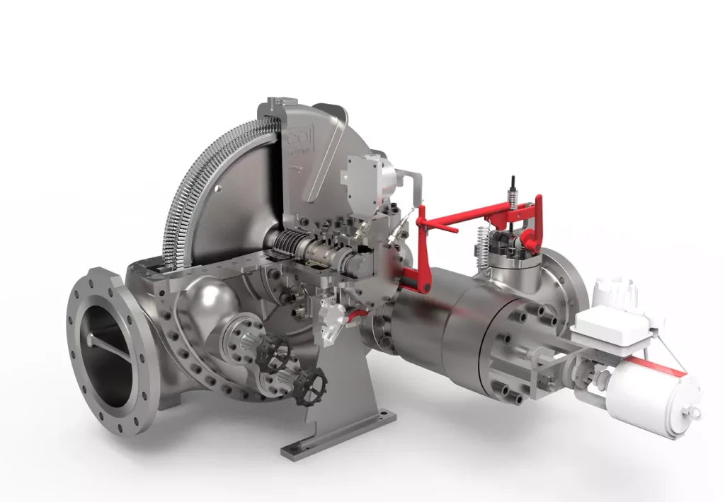
We design, manufacture and assembly Power Machines such as – diesel generators, electric motors, vibration motors, pumps, steam engines and steam turbines
EMS Power Machines is a global power engineering company, one of the five world leaders in the industry in terms of installed equipment. The companies included in the company have been operating in the energy market for more than 60 years.
EMS Power Machines manufactures steam turbines, gas turbines, hydroelectric turbines, generators, and other power equipment for thermal, nuclear, and hydroelectric power plants, as well as for various industries, transport, and marine energy.
EMS Power Machines is a major player in the global power industry, and its equipment is used in power plants all over the world. The company has a strong track record of innovation, and it is constantly developing new and improved technologies.
Here are some examples of Power Machines’ products and services:
- Steam turbines for thermal and nuclear power plants
- Gas turbines for combined cycle power plants and industrial applications
- Hydroelectric turbines for hydroelectric power plants
- Generators for all types of power plants
- Boilers for thermal power plants
- Condensers for thermal power plants
- Reheaters for thermal power plants
- Air preheaters for thermal power plants
- Feedwater pumps for thermal power plants
- Control systems for power plants
- Maintenance and repair services for power plants
EMS Power Machines is committed to providing its customers with high-quality products and services. The company has a strong reputation for reliability and innovation. Power Machines is a leading provider of power equipment and services, and it plays a vital role in the global power industry.
EMS Power Machines, which began in 1961 as a small factory of electric motors, has become a leading global supplier of electronic products for different segments. The search for excellence has resulted in the diversification of the business, adding to the electric motors products which provide from power generation to more efficient means of use.