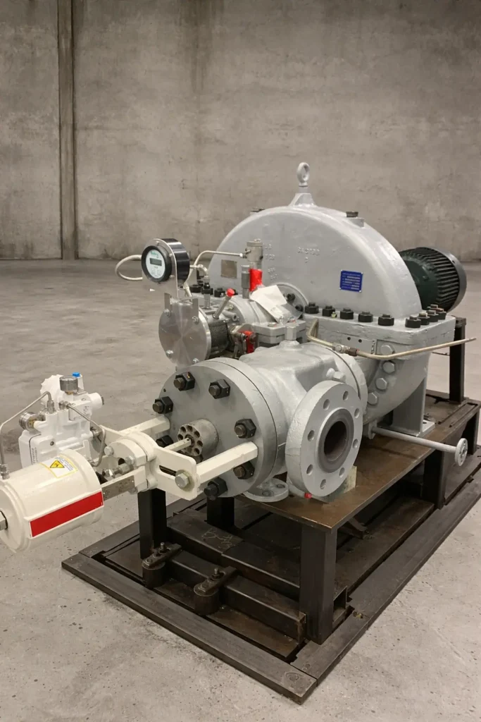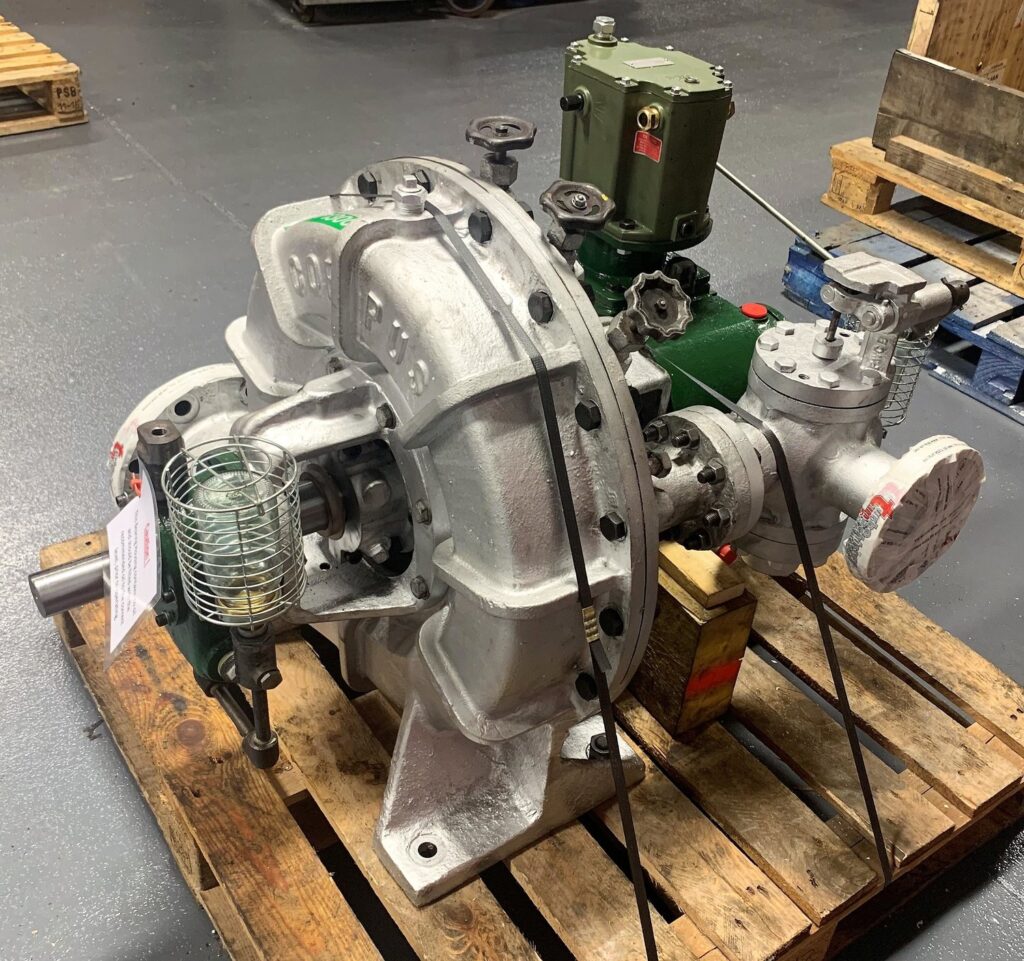
Coppus Steam Turbine: The Coppus steam turbine is a specialized industrial turbine best known for its reliability, simplicity, and long service life. It has been widely used in refineries, chemical plants, pulp and paper mills, steel plants, and other heavy industrial facilities where steam is already available as part of the process. Rather than being designed for large-scale power generation like utility turbines, Coppus turbines are primarily intended for mechanical drive applications and modest electrical generation within industrial plants.
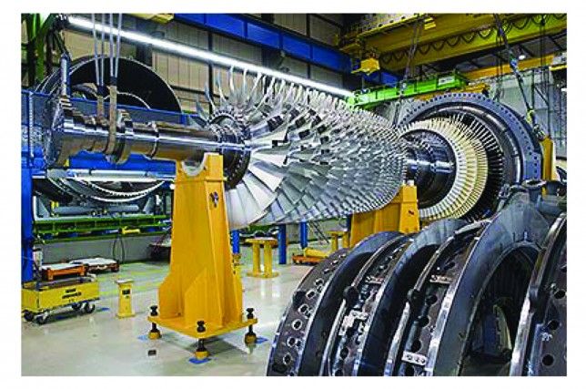
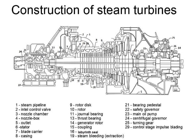
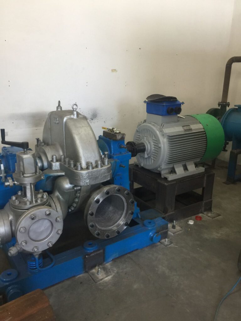
At its core, a Coppus steam turbine converts the thermal energy of steam into rotational mechanical energy. High-pressure steam enters the turbine and expands through a series of nozzles, accelerating as it does so. This high-velocity steam is directed onto turbine blades mounted on a rotating shaft. As the steam changes direction and velocity while passing over the blades, it transfers energy to the rotor, causing it to spin. The rotating shaft can then be connected directly to equipment such as pumps, compressors, blowers, fans, or generators.
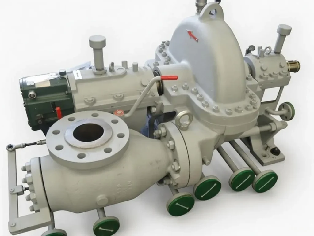
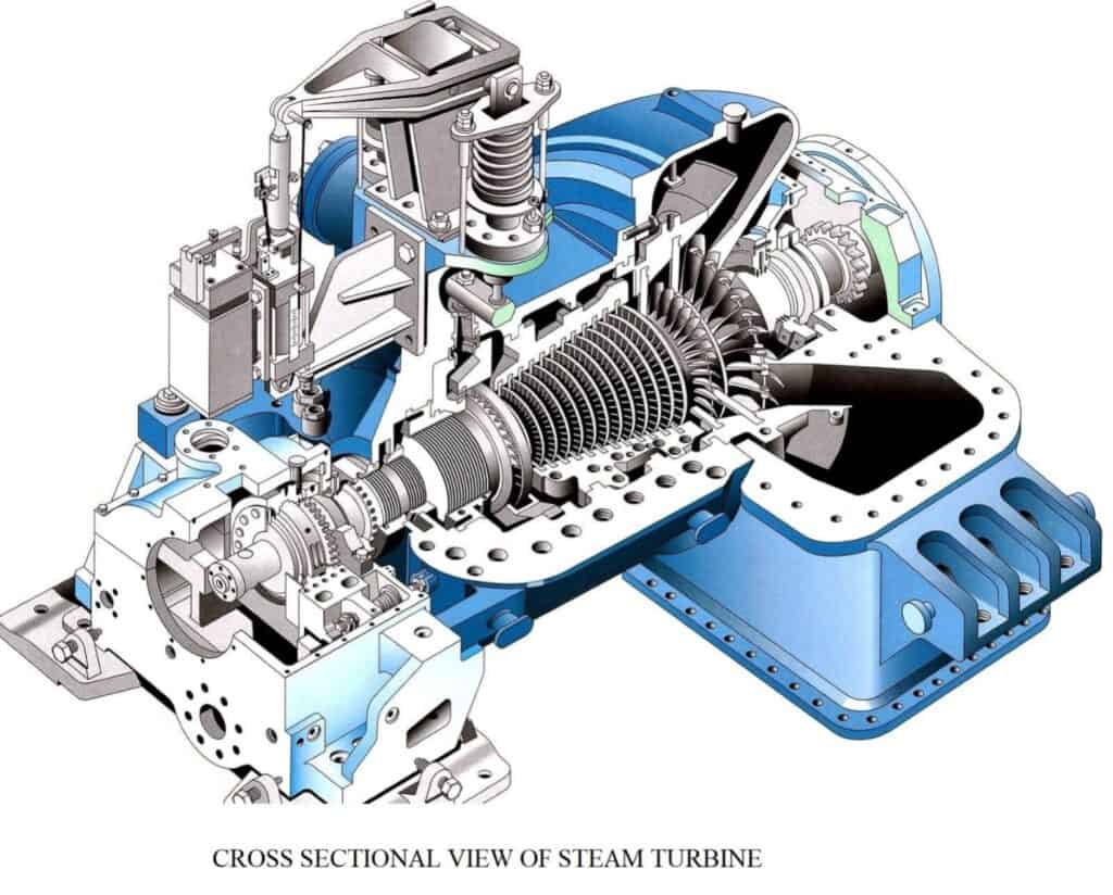
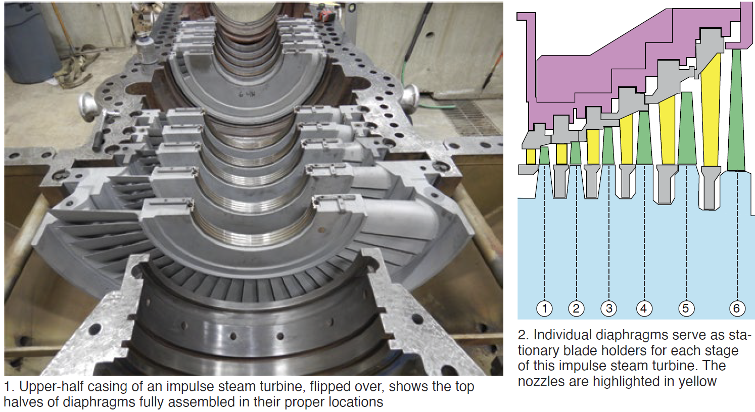
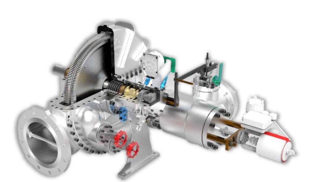
One of the defining characteristics of Coppus steam turbines is their rugged mechanical design. They are typically built as single-stage or simple multi-stage impulse turbines. This design choice reduces complexity and makes the machines easier to maintain compared to large reaction turbines used in power stations. The impulse principle means that most of the pressure drop occurs in the stationary nozzles, while the moving blades primarily extract kinetic energy from the steam jet. This approach is well suited to industrial environments where steam conditions may vary and where absolute efficiency is less critical than reliability and durability.
Coppus turbines are commonly used as back-pressure or condensing turbines, depending on the needs of the process. In back-pressure operation, steam exits the turbine at a controlled pressure and is then used for heating or other process requirements. This allows plants to extract useful mechanical work from steam while still meeting downstream thermal needs. In condensing operation, the exhaust steam is routed to a condenser where it is cooled and converted back into water, allowing for greater energy extraction but requiring additional equipment.
Another important feature of Coppus turbines is their ability to operate over a wide range of steam pressures and flow rates. Industrial steam systems are often subject to fluctuations caused by changing process demands. Coppus turbines are designed to tolerate these variations without excessive wear or loss of stability. Governors and control valves regulate steam admission to maintain the desired speed or power output, even when inlet conditions change.
Speed control is a critical aspect of steam turbine operation, especially for mechanical drives. Coppus turbines often use mechanical or hydraulic governors that respond quickly to load changes. When the driven equipment demands more power, the governor opens the steam valve to admit more steam. When demand decreases, the valve closes accordingly. This direct and responsive control system helps protect both the turbine and the driven machinery from overspeed or sudden load loss.
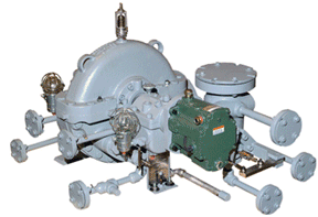
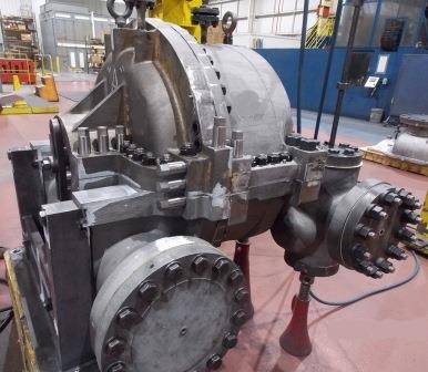
From a construction standpoint, Coppus turbines are typically built with heavy casings, robust shafts, and generously sized bearings. These features contribute to their long operating life. Many Coppus turbines remain in service for decades, often outlasting the original process equipment they were installed to drive. Routine maintenance usually focuses on bearings, seals, control mechanisms, and periodic inspection of nozzles and blades.
Maintenance requirements are generally modest compared to more complex turbine systems. Because the design is relatively simple, plant maintenance personnel can often perform inspections and minor repairs without specialized tools or extensive downtime. This has made Coppus turbines particularly attractive in facilities where continuous operation is essential and shutdowns are costly.
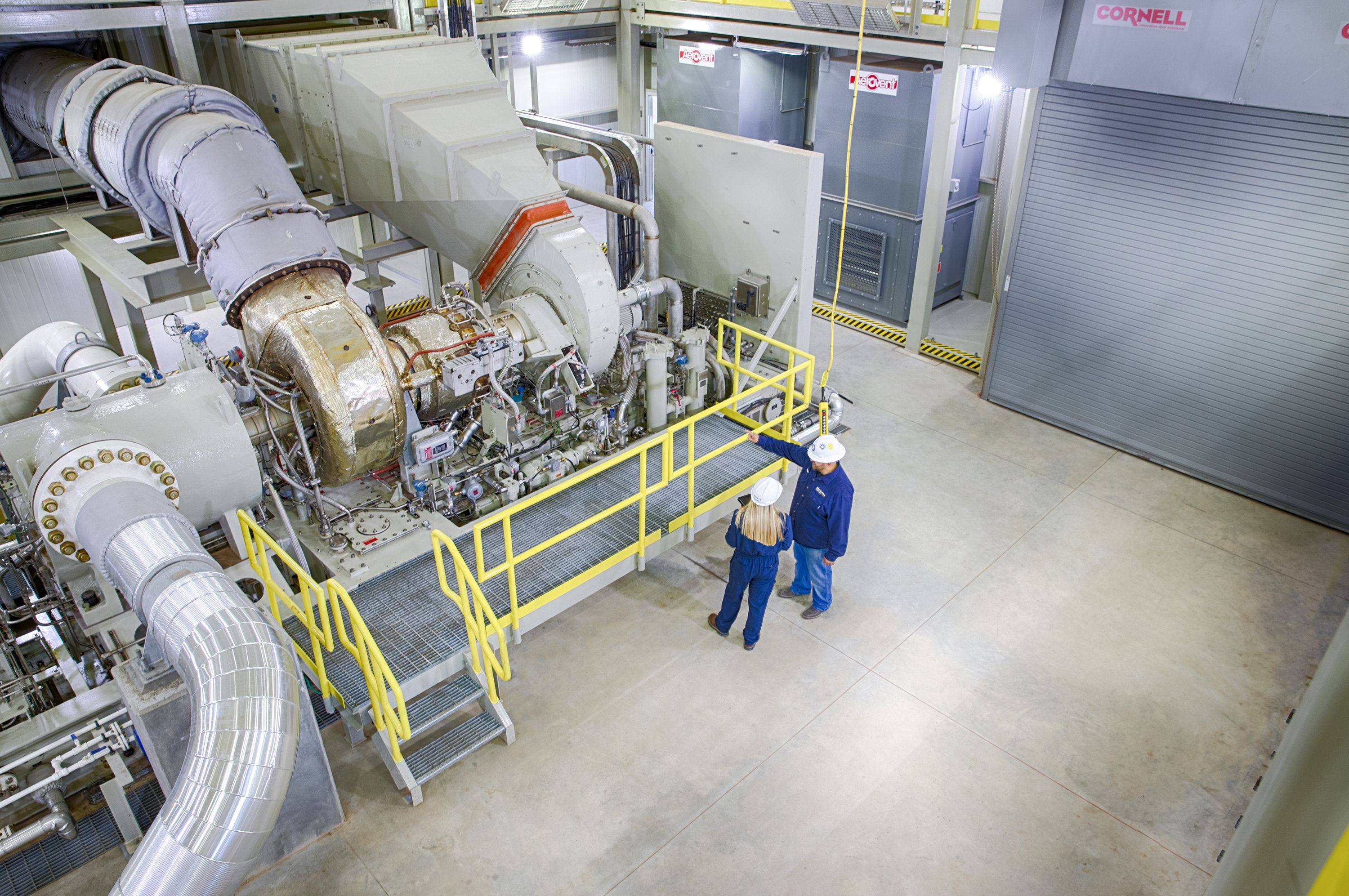
Another reason for their continued use is their compatibility with existing steam systems. Many industrial plants generate steam as a byproduct of other operations, such as boilers used for heating or chemical reactions. Installing a Coppus steam turbine allows plants to recover energy that would otherwise be wasted through pressure reduction valves. In this role, the turbine functions as an energy recovery device, improving overall plant efficiency without requiring major changes to the steam infrastructure.
Although newer technologies such as electric variable-speed drives and gas turbines have replaced steam turbines in some applications, Coppus turbines remain relevant in industries where steam is abundant and reliable. They are especially valued in environments where electrical power may be expensive, unreliable, or where mechanical drive offers advantages in simplicity and robustness.
In summary, the Coppus steam turbine represents a practical and proven approach to industrial energy conversion. It is not designed to achieve the highest possible thermal efficiency, but rather to deliver dependable mechanical power under demanding conditions. Its straightforward impulse design, tolerance for variable steam conditions, ease of maintenance, and long service life have made it a trusted piece of equipment in industrial plants around the world. Even in modern facilities, Coppus turbines continue to play a quiet but important role in converting steam into useful work.
Another notable aspect of Coppus steam turbines is their adaptability to different installation layouts and operating philosophies. They can be mounted horizontally or vertically, depending on space constraints and the nature of the driven equipment. In older plants, it is common to find Coppus turbines installed in tight mechanical rooms or integrated directly into process lines where space efficiency mattered as much as performance. This flexibility made them a practical choice during periods of rapid industrial expansion when plants were designed around function rather than uniform standards.
The materials used in Coppus steam turbines are selected to withstand harsh operating environments. Steam in industrial settings is not always perfectly clean or dry. It may carry small amounts of moisture, scale, or chemical contaminants. Coppus turbines are built with blade and nozzle materials that resist erosion and corrosion, helping maintain performance over long periods. While poor steam quality will still increase wear, these turbines tend to degrade gradually rather than fail suddenly, giving operators time to plan maintenance.
Sealing systems in Coppus turbines are typically straightforward, relying on labyrinth seals rather than complex mechanical seals. Labyrinth seals reduce steam leakage along the shaft while avoiding direct contact between rotating and stationary parts. This design minimizes friction and wear, which is especially important for machines expected to run continuously for years. Even as seals wear over time, performance loss is usually modest and predictable.
Bearings are another area where Coppus turbines emphasize durability over sophistication. Most units use plain journal bearings lubricated by oil systems that are simple and easy to monitor. These bearings can tolerate high loads and minor misalignment, which is valuable in industrial settings where foundations may settle or connected equipment may introduce vibration. With proper lubrication and temperature monitoring, bearing failures are relatively rare.
Coppus turbines are also known for their straightforward startup and shutdown procedures. Unlike large power-generation turbines that require long warm-up times and strict thermal management, Coppus turbines can often be brought online relatively quickly. Operators still need to follow proper procedures to avoid thermal shock, but the machines are forgiving enough to accommodate the realities of industrial operation. This makes them well suited to plants where steam availability or process demand can change on short notice.
In terms of efficiency, Coppus turbines are optimized for reliability and flexibility rather than peak performance. Their efficiency is generally lower than that of modern, high-stage turbines, especially at partial loads. However, in many applications, the steam used by the turbine would otherwise be throttled or vented. In those cases, even a modestly efficient turbine represents a net gain in energy utilization. This perspective has kept Coppus turbines relevant in energy-conscious facilities focused on reducing waste rather than achieving textbook efficiency numbers.
Noise and vibration characteristics are another practical consideration. Coppus turbines are typically quieter and smoother than many alternative prime movers, particularly large reciprocating engines. Properly maintained units operate with steady rotation and minimal vibration, which reduces stress on foundations and connected machinery. This contributes to lower long-term maintenance costs across the entire drive system.
Over time, Coppus has developed a wide range of turbine sizes and ratings to match different applications. Smaller units may produce only a few hundred horsepower, while larger industrial models can deliver several thousand horsepower. This range allows plants to standardize on a familiar technology across multiple processes, simplifying training, spare parts inventory, and maintenance practices.
Modern Coppus turbines may incorporate updated control systems while retaining the core mechanical design. Electronic governors, improved instrumentation, and enhanced safety systems can be added to meet current operational and regulatory requirements. These updates allow older turbine concepts to integrate smoothly into modern control rooms without sacrificing the robustness that made them valuable in the first place.
Safety is an essential consideration in steam turbine operation, and Coppus turbines include features to protect both equipment and personnel. Overspeed trip mechanisms are standard, ensuring that the turbine shuts down automatically if rotational speed exceeds safe limits. Relief valves, protective casings, and clear operating procedures further reduce risk in high-energy steam environments.
In many plants, Coppus steam turbines have become part of the institutional memory. Operators and maintenance technicians often trust them because they understand how they behave under stress and how they fail when problems arise. This familiarity can be just as important as technical specifications, especially in facilities where downtime has serious economic consequences.
Overall, the continued use of Coppus steam turbines reflects a broader industrial reality. In environments where steam is readily available, conditions are demanding, and simplicity matters, these turbines offer a dependable solution. They may not be flashy or cutting-edge, but they perform their role consistently and predictably. That quiet reliability is the reason Coppus steam turbines remain in service long after many newer technologies have come and gone.
The role of Coppus steam turbines in energy recovery deserves special attention. In many industrial plants, steam pressure must be reduced to meet process requirements. Traditionally, this reduction is handled by pressure-reducing valves, which dissipate excess energy as heat and noise. By replacing or supplementing these valves with a Coppus steam turbine, plants can convert otherwise wasted pressure energy into useful mechanical or electrical power. This approach improves overall plant efficiency without increasing fuel consumption in the boiler.
In these energy recovery applications, Coppus turbines often operate continuously at steady conditions. This type of service suits their design philosophy well. The turbine runs at a constant speed, driving a generator or mechanical load while exhausting steam at a pressure suitable for downstream use. Because the turbine is not required to follow rapid load changes, mechanical stress is reduced, further extending service life.
Another important application is emergency or backup power generation. In facilities where steam is available even during electrical outages, a Coppus turbine can drive an essential pump or generator to support safe shutdown procedures. This capability is especially valuable in refineries and chemical plants, where loss of circulation or cooling can quickly become hazardous. The independence from external electrical supplies adds a layer of resilience to plant operations.
From an operational standpoint, operators often appreciate the predictability of Coppus turbines. Their response to changes in steam flow, load, or pressure is gradual and easy to observe. This allows experienced personnel to diagnose developing issues by sound, vibration, or temperature trends. Subtle changes in operating behavior can signal nozzle fouling, bearing wear, or governor issues long before a serious failure occurs.
The longevity of Coppus turbines also means that many units in service today were manufactured decades ago. This creates both challenges and advantages. On the challenge side, older machines may lack modern instrumentation or safety features. On the advantage side, their simple construction makes retrofitting feasible. Temperature sensors, vibration monitors, and electronic controls can often be added without major redesign. This ability to modernize extends the useful life of existing equipment and avoids the cost of full replacement.
Spare parts availability is another practical concern. Coppus turbines are designed with standardized components wherever possible. Nozzles, blades, bearings, and seals follow established patterns rather than highly customized designs. This simplifies fabrication and repair, even when original parts are no longer readily available. In many cases, local machine shops can produce replacement components based on drawings or worn samples.
Training requirements for Coppus turbines are relatively modest. Operators do not need advanced turbine theory to run them safely and effectively. Basic understanding of steam conditions, lubrication, speed control, and safety interlocks is usually sufficient. This makes Coppus turbines suitable for plants with limited access to specialized turbine engineers.
Environmental considerations also play a role in their continued use. Steam turbines produce no direct combustion emissions at the point of use. When driven by steam generated from waste heat or byproduct fuels, the overall environmental impact can be significantly lower than that of alternative prime movers. In energy recovery installations, the turbine effectively reduces waste, aligning with modern sustainability goals even though the technology itself is not new.
It is also worth noting that Coppus turbines are often conservative in their ratings. Nameplate power and speed limits typically include generous safety margins. This conservative approach reduces the likelihood of overstressing components during abnormal operation. While it may result in slightly larger or heavier machines, the trade-off favors reliability and long-term stability.
In real-world plant conditions, this conservative design philosophy pays off. Coppus turbines tend to tolerate operator error, transient upsets, and imperfect maintenance better than more tightly optimized machines. This tolerance does not eliminate the need for proper care, but it reduces the consequences of inevitable human and process variability.
In conclusion, the enduring presence of Coppus steam turbines is not accidental. They fill a specific niche where steam is available, reliability is paramount, and simplicity outweighs the pursuit of maximum efficiency. Through energy recovery, mechanical drive, and auxiliary power applications, these turbines continue to deliver value in industrial environments. Their ongoing relevance reflects a design approach grounded in practicality rather than trends, and that approach remains just as important today as it was when the first Coppus turbines were built.
Coppus Steam Turbine Type for Your Process
Choosing the correct Coppus steam turbine type for a given process starts with understanding how the turbine will fit into the overall steam and mechanical system. Coppus turbines are not one-size-fits-all machines. They are built in several configurations, each intended to serve a particular operating role. The right choice depends less on theoretical efficiency and more on how the turbine will be used day after day in real plant conditions.
The first major distinction to consider is whether the turbine will be used primarily as a mechanical drive or for power generation. In many industrial plants, Coppus steam turbines are installed to drive pumps, compressors, fans, blowers, or mills directly. In these applications, shaft speed, torque characteristics, and load stability are the main concerns. For generator service, speed regulation and electrical stability become more important. Coppus offers turbine designs suited to both roles, but the internal configuration and control approach may differ.
One of the most common Coppus turbine types is the single-stage impulse turbine. This design is often selected for simple, robust mechanical drive applications where steam conditions are relatively high and the exhaust pressure can be matched to process needs. Single-stage turbines are compact, easy to maintain, and highly tolerant of variations in steam quality. They are well suited for driving centrifugal pumps or fans that operate at a constant speed and load.
For processes that require greater power output or improved efficiency over a wider operating range, multi-stage impulse turbines may be a better fit. These turbines extract energy from the steam across multiple rows of nozzles and blades, allowing more controlled expansion. While still mechanically straightforward, multi-stage units offer smoother torque delivery and better performance at partial load. This makes them suitable for compressors or larger mechanical drives with more demanding power requirements.
Another key choice is between back-pressure and condensing turbine configurations. A back-pressure Coppus steam turbine is selected when exhaust steam is needed for downstream process use. In this case, the turbine becomes part of the steam distribution system. The exhaust pressure is carefully controlled to meet heating, drying, or chemical process requirements. Back-pressure turbines are common in plants where steam serves multiple purposes and energy recovery is a priority.
Condensing Coppus turbines are chosen when maximum energy extraction from the steam is desired and there is no need for the exhaust steam in the process. These turbines exhaust into a condenser operating below atmospheric pressure. This increases the usable energy from the steam but adds complexity in the form of cooling water systems and condensate handling. Condensing turbines are more often used for generator applications or where steam availability exceeds process demand.
Another important factor is whether the process requires constant speed or variable speed operation. Many Coppus turbines are designed for constant-speed service, especially when driving generators or fixed-speed machinery. For applications where speed variation is required, such as certain pumping or milling processes, control systems must be selected carefully. While steam turbines are not as flexible as modern electric drives in speed variation, Coppus turbines can accommodate moderate speed control within defined limits.
Steam conditions play a critical role in turbine selection. Inlet pressure, temperature, and flow rate must match the turbine’s design envelope. Coppus turbines are available for a wide range of steam pressures, from moderate industrial levels to very high pressures. If the steam supply is variable or subject to interruptions, the turbine type should be chosen for stability rather than peak output. Conservative sizing is often preferred to ensure reliable operation under less-than-ideal conditions.
The nature of the driven process also influences turbine type. Processes with steady loads, such as circulation pumps or constant-flow compressors, are ideal candidates for simpler turbine designs. Processes with frequent load changes or intermittent operation may require more responsive governing systems and more robust mechanical margins. Understanding load behavior over time is just as important as knowing the maximum power requirement.
Installation constraints should not be overlooked. Available floor space, foundation strength, shaft alignment, and connection to existing equipment can all affect turbine selection. Coppus turbines are available in horizontal and vertical configurations, allowing them to be integrated into existing layouts. In retrofit projects, selecting a turbine type that minimizes structural and piping changes can significantly reduce installation cost and downtime.
Maintenance philosophy is another deciding factor. Plants with limited maintenance resources often prefer simpler turbine types with fewer stages and mechanical controls. Plants with strong maintenance programs may opt for more complex configurations if they offer operational advantages. Coppus turbines are generally forgiving, but matching the turbine type to the plant’s maintenance capability improves long-term reliability.
Finally, safety and regulatory requirements must be considered. Overspeed protection, pressure containment, and control systems must align with plant standards and local regulations. Some processes may require redundant protection or enhanced monitoring, influencing the choice of turbine type and accessories.
In summary, selecting the right Coppus steam turbine type for a process is a practical engineering decision rooted in how the turbine will actually be used. By considering the driven equipment, steam conditions, exhaust requirements, load behavior, installation constraints, and maintenance capability, plant engineers can choose a Coppus turbine that delivers reliable service over decades. The best choice is not the most advanced or efficient design, but the one that fits the process with the least compromise and the greatest long-term stability.
Beyond the basic turbine configuration, auxiliary systems play a major role in matching a Coppus steam turbine to a specific process. These supporting systems are often as important as the turbine itself, because they determine how smoothly and safely the machine operates over time. When selecting a turbine type, it is essential to consider how these systems will integrate with existing plant infrastructure.
The steam admission system is one such consideration. Coppus turbines can be equipped with different valve arrangements depending on control requirements. Simple hand valves may be sufficient for steady, noncritical applications, while automatically controlled throttle valves are preferred for processes that experience load changes. For more sensitive applications, a turbine with a well-matched governor and responsive control valve provides better speed stability and equipment protection.
Lubrication systems also influence turbine selection. Smaller Coppus turbines may use simple ring-oiled bearings, while larger units require forced lubrication systems with pumps, coolers, and filters. The choice depends on turbine size, speed, and duty cycle. In plants where maintenance attention is limited, simpler lubrication arrangements reduce the risk of failure due to pump or filter issues. In higher-power applications, more robust oil systems improve bearing life and reliability.
Another factor is exhaust handling. In back-pressure applications, the turbine exhaust must integrate smoothly into the downstream steam header. Poorly matched exhaust conditions can lead to unstable turbine operation or process disruptions. Selecting a turbine designed for the required exhaust pressure range helps avoid these problems. In condensing applications, the condenser capacity and vacuum stability must be compatible with the turbine’s exhaust characteristics.
Process continuity requirements may also dictate turbine selection. In continuous-process plants, unplanned downtime can be extremely costly. In these cases, a slightly oversized turbine operating well below its maximum rating may be preferred. This approach reduces mechanical stress and allows the turbine to handle temporary overloads without shutdown. Coppus turbines are well suited to this conservative sizing philosophy.
Environmental and operating conditions around the turbine should not be ignored. High ambient temperatures, dusty environments, or corrosive atmospheres can affect turbine performance and maintenance needs. Coppus turbines intended for such conditions may be specified with special materials, protective coatings, or enclosures. Selecting the right turbine type upfront avoids premature wear and frequent repairs.
Integration with plant control systems is another modern consideration. While Coppus turbines are traditionally mechanical machines, many installations now require electronic monitoring and control. Turbine types that can accept electronic governors, speed sensors, and remote shutdown signals are easier to integrate into distributed control systems. This is especially important in plants with centralized control rooms and strict safety protocols.
The startup and operating profile of the process also influences turbine choice. Processes that require frequent starts and stops may benefit from simpler turbine designs that tolerate thermal cycling. More complex turbines with tighter clearances may experience greater wear under such conditions. Understanding how often the turbine will be started, stopped, or idled helps guide the selection toward a suitable type.
Economic considerations inevitably come into play. The initial cost of the turbine, installation expense, operating efficiency, and maintenance cost must be weighed together. In many cases, the most economical choice over the turbine’s lifetime is not the lowest-cost unit upfront, but the one that offers stable operation and minimal downtime. Coppus turbines are often selected precisely because their long service life offsets modest efficiency losses.
It is also important to consider future process changes. Steam conditions, production rates, or equipment configurations may evolve over time. Selecting a turbine type with some operational flexibility allows the plant to adapt without replacing the turbine. Coppus turbines with generous design margins are particularly well suited to this approach.
In practical terms, selecting a Coppus steam turbine type is often an iterative process. Engineers evaluate process requirements, consult operating experience, and balance technical and economic factors. The final choice reflects not only calculated performance, but also confidence that the turbine will behave predictably in everyday operation.
Ultimately, the best Coppus steam turbine type for a process is one that disappears into the background of plant operations. It runs reliably, responds calmly to changes, and demands little attention beyond routine care. When properly selected and applied, a Coppus turbine becomes a stable, long-term asset rather than a source of ongoing concern.
Another layer in selecting the appropriate Coppus steam turbine type involves understanding how the turbine will interact with upstream and downstream process equipment. Steam systems in industrial plants are rarely isolated. They are interconnected networks where changes in one area can affect pressures, flows, and temperatures elsewhere. A turbine that is well matched to its immediate load but poorly matched to the broader steam system can create operational issues over time.
Upstream boiler characteristics are especially important. Boilers have limits on how quickly they can respond to changes in steam demand. If a turbine draws steam too aggressively during load increases, boiler pressure can drop and disrupt other processes. In such cases, a turbine type with smoother control characteristics and slower response may actually be preferable to a more aggressive design. Coppus turbines are often chosen for their stable, predictable steam consumption, which helps maintain system balance.
Downstream steam users also influence turbine selection. In back-pressure applications, the turbine must deliver exhaust steam at a pressure and quality that downstream equipment can accept. If downstream demand varies significantly, the turbine type and control system must accommodate those variations without causing excessive pressure swings. Some Coppus turbine configurations handle these conditions better due to their nozzle arrangement and governing style.
Mechanical coupling considerations are another practical factor. Direct-coupled turbines require precise speed matching and alignment with the driven equipment. In some processes, gearboxes or belt drives are used to match turbine speed to load requirements. The turbine type selected must be compatible with the chosen coupling method. Higher-speed turbines may require reduction gearing, while lower-speed designs can often be coupled directly, simplifying installation and maintenance.
Vibration tolerance is also relevant when selecting a turbine type. Some processes involve equipment that introduces cyclic loads or flow-induced vibration. A turbine with a heavier rotor and robust bearings may be better suited to such conditions. Coppus turbines are generally conservative in this regard, but specific models are better suited to high-inertia or pulsating loads than others.
Another consideration is steam availability during abnormal operating conditions. In some plants, steam pressure may drop during startup, shutdown, or upset conditions. A turbine that stalls or becomes unstable at reduced pressure can complicate recovery. Selecting a turbine type that can continue operating at reduced inlet pressure, even at lower output, improves overall process resilience.
The human factor also plays a role. Operators are more comfortable with equipment they understand. If a plant already has experience with a certain Coppus turbine type, choosing a similar configuration for a new process reduces training needs and operating risk. Familiar controls, startup procedures, and maintenance practices contribute to smoother long-term operation.
Documentation and standardization matter as well. Plants often develop internal standards for equipment selection. Coppus turbines that align with these standards are easier to approve, install, and support. Deviating from established turbine types should be justified by clear process benefits, not just marginal performance gains.
In facilities where safety margins are emphasized, turbine selection may intentionally favor lower operating speeds, thicker casings, and simpler control systems. These features reduce the consequences of component failure and make abnormal conditions easier to manage. Coppus turbines, with their traditionally conservative design, fit well into such safety-focused environments.
Over the life of the turbine, operational data becomes a valuable resource. Turbine types that provide clear, interpretable signals through pressure, temperature, and speed measurements help operators make informed decisions. Selecting a turbine configuration that supports straightforward monitoring improves both reliability and confidence in operation.
At a strategic level, selecting the right Coppus steam turbine type supports broader plant goals. Whether the objective is energy recovery, cost control, reliability, or operational simplicity, the turbine should reinforce that objective rather than work against it. A well-chosen turbine becomes part of the solution rather than a constraint.
In the end, Coppus steam turbine selection is less about finding an ideal theoretical match and more about choosing a practical, resilient machine that fits the realities of the process. By considering system interactions, operating behavior, human factors, and long-term plant strategy, engineers can select a turbine type that delivers steady value throughout its service life.
One final but often overlooked aspect of selecting a Coppus steam turbine type is how the turbine will age over time. No industrial process remains static for decades, yet Coppus turbines are commonly expected to operate for that long. A turbine that performs well when new but becomes difficult to operate as conditions drift is not a good long-term choice. This is why many plants favor turbine types that remain stable even as clearances open, controls wear, and steam conditions slowly change.
Wear patterns differ between turbine types. Simpler, single-stage impulse turbines tend to wear in predictable ways. Nozzle erosion, blade edge rounding, and seal leakage develop gradually and are easy to monitor. More complex, higher-performance designs may be more sensitive to wear and may show sharper drops in performance if maintenance is deferred. For plants where inspections are infrequent, this difference can be decisive.
Another long-term consideration is spare parts strategy. Turbine types that share components with other units in the plant reduce inventory and simplify logistics. Coppus turbines have historically emphasized commonality across models, but differences still exist between stages, shaft sizes, and casing designs. Selecting a turbine type that aligns with existing spare parts policies can reduce downtime when repairs are needed.
The availability of skilled support also matters. Even the most robust turbine requires occasional expert attention. Turbine types that are widely used and well understood are easier to support with in-house staff or local service providers. This practical reality often outweighs minor technical advantages offered by less common configurations.
From a lifecycle cost perspective, the chosen turbine type should minimize total ownership cost rather than just purchase price. This includes installation, fuel or steam opportunity cost, maintenance labor, spare parts, and the economic impact of downtime. Coppus turbines are often selected because their predictable behavior makes these costs easier to estimate and control.
Process safety reviews increasingly influence equipment selection. Turbine types that are easy to isolate, depressurize, and inspect fit better into modern safety management systems. Clear casing splits, accessible valves, and visible trip mechanisms reduce risk during maintenance. Coppus turbines traditionally score well in this area due to their straightforward layouts.
Another practical issue is noise and heat exposure in the turbine area. Some turbine types operate with higher exhaust velocities or casing temperatures, which can affect working conditions. Selecting a turbine configuration that minimizes these effects can improve operator comfort and reduce the need for additional shielding or insulation.
As plants modernize, digital monitoring and condition-based maintenance become more common. While Coppus turbines were not originally designed with digital systems in mind, many types adapt well to them. Turbine designs with accessible bearing housings and clear measurement points are easier to instrument with modern sensors. This adaptability extends the useful life of traditional turbine designs in modern operating environments.
It is also worth considering how the turbine will be perceived internally. Equipment that is known to be reliable tends to receive consistent care and attention. Turbine types that operators trust are more likely to be started correctly, monitored properly, and maintained on schedule. This human element reinforces the technical strengths of well-chosen Coppus turbines.
In practical terms, the “right” Coppus steam turbine type is often the one that causes the fewest discussions after installation. It does its job quietly, without frequent adjustments or surprises. Over time, it becomes part of the plant’s normal rhythm rather than a point of concern.
Ultimately, selecting a Coppus steam turbine type for your process is an exercise in realism. It requires accepting the limits of prediction and choosing a design that performs well not just under ideal conditions, but under the imperfect, changing conditions of real industrial operation. When that choice is made carefully, the turbine rewards the plant with decades of dependable service and steady performance.
Coppus Steam Turbines: Model Types for Industrial Reliability
Coppus steam turbines have earned a reputation for industrial reliability largely because of the way their model types are structured around practical operating needs rather than narrow performance targets. Each model family is designed to serve a specific range of pressures, speeds, and power outputs while maintaining a conservative mechanical design. This approach allows plants to select a turbine that fits their process with minimal compromise and predictable long-term behavior.
At the foundation of the Coppus product range are single-stage impulse turbine models. These are among the most widely installed Coppus turbines in industrial service. They are typically used for smaller to medium power applications where simplicity and durability are paramount. The single-stage design limits internal complexity, reduces the number of wear components, and makes inspection straightforward. For processes such as circulation pumps, cooling fans, or small compressors, these models provide dependable service with minimal attention.
For higher power requirements or applications where steam conditions are less favorable, Coppus offers multi-stage impulse turbine models. These models distribute the steam energy extraction across multiple stages, reducing blade loading and improving efficiency. From a reliability standpoint, this staged approach lowers mechanical stress and helps maintain stable operation across a broader load range. Multi-stage models are often chosen for larger compressors, process pumps, or generator drives where steady, continuous operation is expected.
Another important model distinction is based on exhaust configuration. Back-pressure turbine models are designed to deliver exhaust steam at a controlled pressure for downstream use. These models are common in plants that rely on steam for heating, drying, or chemical reactions. Reliability in this context means not only mechanical integrity, but also consistent exhaust pressure. Coppus back-pressure models are built with governing systems that emphasize smooth pressure control rather than aggressive load following, which supports stable plant operation.
Condensing turbine models represent another segment of the Coppus lineup. These models are used when maximum energy extraction from steam is required and when downstream steam use is limited or nonexistent. Condensing models operate with a condenser under vacuum conditions, allowing greater expansion of the steam. While this adds system complexity, Coppus condensing turbines retain the same conservative mechanical philosophy, prioritizing stable operation and long service life over peak efficiency.
Coppus also offers turbine models optimized for mechanical drive versus generator service. Mechanical drive models are configured to deliver high starting torque and stable shaft speed under load. These features are essential for equipment such as compressors and mills that impose significant inertia or resistance during startup. Generator-drive models, by contrast, emphasize precise speed regulation and compatibility with electrical control systems. Both model types are engineered with reliability as the primary objective.
Speed rating is another key differentiator among Coppus turbine models. Some models are designed for direct coupling to driven equipment at relatively low speeds, while others operate at higher speeds and require reduction gearing. Lower-speed models generally offer increased robustness and simpler maintenance, making them attractive in harsh industrial environments. Higher-speed models allow more compact designs and higher power density, but still maintain conservative stress levels compared to utility-scale turbines.
Coppus turbine models are also classified by their governing and control systems. Traditional mechanical governors are common in many installations and are valued for their simplicity and independence from electrical power. More recent models can accommodate hydraulic or electronic governors, improving speed control and integration with modern plant systems. Regardless of the control method, Coppus designs emphasize fail-safe behavior and predictable response to load changes.
From a reliability perspective, casing and rotor design are central to Coppus model differentiation. Casings are typically thick and rigid, providing structural stability and resistance to pressure and thermal distortion. Rotors are designed with generous safety margins and balanced to minimize vibration. These features reduce sensitivity to alignment issues, foundation movement, and thermal cycling, all of which are common in industrial environments.
Another factor contributing to reliability is the way Coppus turbine models handle off-design operation. Industrial processes rarely operate at a single steady point. Coppus turbines are designed to tolerate partial load operation, steam pressure fluctuations, and gradual changes in operating conditions without loss of stability. This tolerance is built into the model designs rather than added through complex controls.
Model selection also reflects maintenance philosophy. Some Coppus models are optimized for rapid inspection and servicing, with easy access to nozzles, blades, and bearings. These models are particularly valued in plants where maintenance windows are short and downtime is costly. The ability to inspect and repair a turbine quickly contributes directly to overall reliability.
In industrial practice, reliability is not defined by the absence of failures, but by the predictability of behavior and the ease of recovery when issues arise. Coppus steam turbine model types are designed with this definition in mind. When problems occur, they tend to develop slowly and provide clear warning signs, allowing planned intervention rather than emergency shutdown.
In summary, Coppus steam turbines achieve industrial reliability through thoughtful model differentiation rather than excessive complexity. By offering model types tailored to specific duties, steam conditions, and control needs, Coppus allows plants to choose turbines that align with real operating conditions. This alignment, combined with conservative mechanical design and practical controls, is the reason Coppus turbine models continue to be trusted in demanding industrial environments.
A deeper look at Coppus steam turbine model types also shows how reliability is reinforced through standardization and incremental variation rather than radical design changes. Over time, Coppus has refined its turbine families by adjusting dimensions, stage counts, and materials while keeping the basic architecture consistent. This evolutionary approach reduces unexpected behavior and allows operating experience from older units to carry forward into newer models.
One area where this consistency is especially valuable is in bearing and shaft design. Across many Coppus model types, bearing arrangements follow familiar patterns. Journal bearings are sized generously and placed to support stable rotor dynamics. Thrust bearings are designed to handle axial loads under both normal and upset conditions. Because these features are common across models, maintenance teams develop a strong understanding of how they behave, which improves diagnostic accuracy and response time.
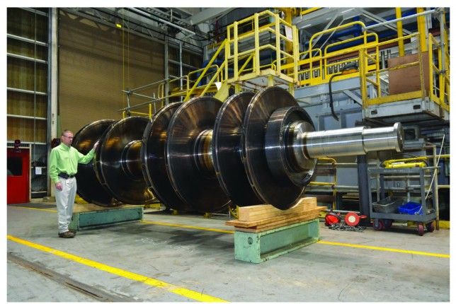
Rotor construction also reflects a reliability-first philosophy. Coppus rotors are typically solid and relatively heavy compared to more efficiency-driven designs. While this increases inertia, it also smooths operation and dampens speed fluctuations. In mechanical drive applications, this inertia helps protect driven equipment from sudden torque changes. In generator applications, it contributes to stable frequency control.
Nozzle and blade arrangements differ between model types, but they share common design principles. Steam velocities are kept within conservative limits to reduce erosion and fatigue. Blade attachment methods emphasize mechanical security over ease of manufacture. These choices reduce the likelihood of blade failure, which is one of the most serious risks in any turbine installation.
Casing design varies by model type depending on pressure rating and exhaust configuration, but all Coppus casings are built to resist distortion and leakage. Split casings are common, allowing internal inspection without disturbing the foundation or major piping. This feature supports proactive maintenance, which is a key contributor to long-term reliability.
Another important reliability factor is how Coppus turbine models handle abnormal events. Overspeed protection systems are integral to all models, with mechanical trips that act independently of external power or control systems. This independence ensures that the turbine can protect itself even during plant-wide power failures or control system faults.
Thermal behavior is also carefully managed across model types. Clearances are designed to accommodate uneven heating during startup and shutdown. This reduces the risk of rotor rubs and casing distortion, which are common causes of damage in more tightly optimized machines. Coppus turbines tolerate slower or less precise startup procedures without serious consequences, which aligns with real-world operating practices.
Model differentiation also reflects the range of industries that use Coppus turbines. Some model types are tailored for continuous, steady-duty service typical of chemical and refining processes. Others are better suited to cyclic operation found in batch processing or auxiliary systems. By matching the model type to the duty cycle, plants can achieve higher effective reliability even if theoretical efficiency is not maximized.
Spare parts interchangeability is another advantage of the Coppus model strategy. Many internal components share dimensions or design features across multiple model types. This reduces the number of unique spares that must be stocked and shortens repair times when issues arise. In reliability-focused operations, this logistical simplicity is a major benefit.
The conservative rating of Coppus turbine models further supports dependable operation. Nameplate ratings typically include substantial safety margins, allowing the turbine to operate comfortably below its mechanical limits. This reduces wear rates and improves tolerance to occasional overloads or steam condition excursions.
In practice, the reliability of a Coppus turbine model is often measured by how rarely it becomes the limiting factor in plant operation. When selected correctly, these turbines run in the background, supporting the process without drawing attention. This low-profile performance is not accidental but is the result of deliberate model design choices focused on stability and longevity.
Ultimately, Coppus steam turbine model types represent a balance between standardization and customization. Each model family addresses a specific operating niche, while sharing common design principles that emphasize strength, simplicity, and predictability. This balance is what allows Coppus turbines to maintain their reputation for industrial reliability across decades of service and across a wide range of demanding applications.
Another way to understand Coppus steam turbine model types is to look at how they support long-term operational planning in industrial facilities. Reliability is not only about how a machine performs today, but also about how well it fits into maintenance schedules, upgrade paths, and plant life-cycle strategies. Coppus models are often selected because they simplify these broader planning efforts.
Many Coppus turbine model types are designed to be forgiving of alignment and foundation imperfections. In older plants, foundations may shift slightly over time, and piping loads may not be perfectly balanced. Turbine models with rigid casings and tolerant bearing arrangements are less sensitive to these realities. This reduces the frequency of alignment-related issues, which are a common source of chronic reliability problems in rotating equipment.
Another planning advantage is the predictable inspection interval associated with Coppus turbines. Because wear mechanisms develop slowly, inspection schedules can be set with confidence. Model types with easily accessible internals support visual inspection of nozzles, blades, and seals without major disassembly. This predictability allows maintenance activities to be aligned with planned outages rather than driven by unexpected failures.
Coppus turbine models also adapt well to partial modernization. Plants may choose to upgrade control systems, add monitoring, or improve lubrication without replacing the turbine itself. Model types with simple mechanical layouts and clear interfaces make these upgrades straightforward. This ability to evolve gradually supports long-term reliability by keeping the turbine compatible with changing plant standards.
The interaction between turbine model type and operating culture is another subtle but important factor. Some plants favor hands-on operation and local control, while others rely heavily on centralized automation. Coppus models can support both approaches. Turbine types with mechanical governors suit manual or semi-automatic operation, while models compatible with electronic control integrate smoothly into automated systems. Matching the model type to the plant’s operating culture reduces the risk of misuse or neglect.
Environmental exposure also influences model selection. Some Coppus turbine models are better suited to outdoor installation or harsh environments due to heavier casings, simplified sealing, and reduced reliance on sensitive electronics. In plants where environmental control is limited, these rugged models contribute directly to reliability by reducing vulnerability to heat, dust, or moisture.
Another reliability consideration is startup reliability after long idle periods. Some industrial turbines are only used during specific operating modes or seasonal demand. Coppus turbine models tend to restart reliably even after extended downtime, provided basic preservation practices are followed. This is partly due to their robust materials and conservative clearances, which reduce the risk of sticking or corrosion-related issues.
From a management perspective, Coppus turbine model types offer consistency across fleets of equipment. Plants with multiple turbines benefit from having similar operating procedures, spare parts, and training requirements. This consistency reduces complexity and the likelihood of errors, which is an often underappreciated contributor to reliability.
Documentation quality also plays a role. Coppus turbine models are typically supported by clear, practical documentation focused on operation and maintenance rather than abstract theory. This helps ensure that knowledge is retained even as personnel change over time. Reliable equipment is easier to keep reliable when the information needed to operate it correctly is accessible and understandable.
In long-running plants, equipment often becomes part of the institutional memory. Coppus turbine models that have proven themselves over decades earn a level of trust that influences future equipment choices. This trust is built on predictable behavior, manageable maintenance, and the absence of unpleasant surprises. Model types that deliver these qualities reinforce the perception of reliability year after year.
Ultimately, Coppus steam turbine model types are designed to support stability rather than optimization. They accept some efficiency trade-offs in exchange for mechanical strength, operational tolerance, and ease of care. In industrial environments where uptime matters more than theoretical performance, this trade-off is not a compromise but a deliberate and effective strategy.
For this reason, Coppus turbines continue to be specified in applications where reliability is non-negotiable. Their model types are not defined by complexity or novelty, but by how well they serve real processes over long periods. That focus on dependable service is what keeps Coppus steam turbines relevant in modern industry.
When examining Coppus steam turbine model types through the lens of industrial reliability, it becomes clear that their value lies as much in what they avoid as in what they include. Many modern machines chase higher efficiency through tighter tolerances, lighter components, and more complex control strategies. Coppus turbine models deliberately avoid pushing these limits, choosing instead to operate comfortably within proven mechanical boundaries.
This design restraint is reflected in how different model types handle thermal stress. Steam turbines experience repeated heating and cooling cycles, especially in plants with variable operating schedules. Coppus models are designed with generous clearances and robust casing structures that accommodate uneven thermal expansion. This reduces the likelihood of casing distortion or rotor rubs, which can quickly escalate into major failures.
Another area where model design supports reliability is in the treatment of steam quality. Industrial steam is rarely ideal. It may contain moisture, trace chemicals, or small particulates. Coppus turbine models are tolerant of these conditions because their blade profiles, materials, and steam velocities are chosen to resist erosion and corrosion. While clean, dry steam is always preferable, these turbines continue to operate acceptably even when steam quality is less than perfect.
Model-specific differences also address varying duty cycles. Some Coppus turbines are intended for continuous base-load operation, while others are better suited to intermittent or standby service. Base-load models emphasize steady-state stability and long wear life. Standby-oriented models focus on reliable starts and rapid availability. Selecting the correct model type for the duty cycle reduces stress on the turbine and improves overall reliability.
Another contributor to dependable operation is the straightforward fault behavior of Coppus turbine models. When problems arise, they tend to manifest as gradual changes in performance rather than sudden failures. Increased vibration, rising bearing temperatures, or reduced output typically provide ample warning. This predictability allows maintenance teams to intervene before damage becomes severe.
Coppus turbine model types also support reliability through clear separation of functions. Steam admission, speed control, lubrication, and protection systems are typically distinct and accessible. This modularity makes troubleshooting easier and reduces the risk that a single fault will cascade into a major outage.
The physical layout of many Coppus models reflects an emphasis on maintainability. Components that require periodic attention are accessible without extensive disassembly. This encourages routine inspection and preventive maintenance, which directly supports long-term reliability. Equipment that is difficult to access is often neglected, regardless of its theoretical durability.
Another practical benefit of Coppus turbine models is their compatibility with conservative operating practices. Many industrial plants prefer to run equipment below maximum ratings to extend service life. Coppus turbines are well suited to this approach because their performance remains stable at reduced loads. They do not rely on operating near design limits to remain efficient or stable.
Over decades of service, many Coppus turbine models have demonstrated the ability to survive changes in process conditions that were never anticipated at the time of installation. Increases or decreases in steam pressure, changes in exhaust requirements, or shifts in load can often be accommodated within the turbine’s design envelope. This flexibility reduces the need for costly replacements when processes evolve.
The reliability of Coppus steam turbine models is also reinforced by institutional knowledge. Because these turbines have been used for so long, best practices for their operation and maintenance are well established. This accumulated experience reduces the learning curve for new installations and helps prevent avoidable mistakes.
In the end, Coppus steam turbine model types represent a mature technology refined by decades of industrial use. Their reliability does not come from cutting-edge features, but from thoughtful design choices that prioritize durability, tolerance, and simplicity. In environments where steady operation matters more than peak performance, these qualities remain invaluable.
That is why Coppus turbines continue to be selected for critical industrial roles. Their model types are shaped by real-world experience, and that experience has consistently shown that conservative design, when applied intelligently, is one of the strongest foundations for industrial reliability.
A Guide to Coppus Steam Turbine Types and Capabilities
Coppus steam turbines are designed to meet the practical demands of industrial environments where reliability, longevity, and predictable performance matter more than peak efficiency. Rather than offering highly specialized machines for narrow operating points, Coppus has developed turbine types that cover broad ranges of steam conditions and duties. This guide explains the main Coppus steam turbine types and the capabilities that define their use in real industrial processes.
Core Design Philosophy
All Coppus steam turbine types share a common design philosophy. They are impulse turbines built with conservative stress levels, robust casings, and simple internal arrangements. The goal is stable, long-term operation under variable conditions. Clearances are generous, materials are selected for durability, and controls are designed to fail safely. This philosophy underpins every turbine type in the Coppus lineup.
Single-Stage Impulse Turbines
Single-stage Coppus turbines are among the simplest and most widely used types. Steam expands through a single set of nozzles and transfers energy to one row of moving blades. These turbines are compact, easy to maintain, and tolerant of changes in steam quality and pressure.
Their capabilities include reliable operation in small to medium power ranges and excellent suitability for mechanical drives such as pumps, fans, and blowers. They are especially effective where steam pressure is relatively high and exhaust pressure requirements are moderate. Because of their simplicity, they are often chosen for applications where maintenance resources are limited or where uptime is critical.
Multi-Stage Impulse Turbines
Multi-stage Coppus turbines extract energy from steam across multiple stages, allowing smoother expansion and improved efficiency over a wider operating range. While still mechanically straightforward, these turbines are capable of higher power outputs and more stable performance at partial load.
These turbines are commonly used for larger mechanical drives and generator applications. Their capabilities include better torque control, reduced blade loading, and improved tolerance of fluctuating loads. They are well suited to compressors and other equipment that demand steady power delivery over long operating periods.
Back-Pressure Turbines
Back-pressure Coppus turbines are designed to exhaust steam at a controlled pressure for downstream process use. Rather than maximizing energy extraction, their primary capability is balancing power generation or mechanical drive with process steam requirements.
These turbines are widely used in plants where steam serves multiple purposes, such as heating, drying, or chemical processing. Their strength lies in stable exhaust pressure control and predictable steam flow. This makes them ideal for energy recovery applications where steam pressure would otherwise be reduced by throttling.
Condensing Turbines
Condensing Coppus turbines are used when the goal is to extract as much energy as possible from the steam. These turbines exhaust into a condenser operating under vacuum, allowing greater expansion of the steam.
Their capabilities include higher power output from a given steam flow and suitability for generator service or standalone power generation. While condensing systems add complexity, Coppus condensing turbines retain the same conservative mechanical design and operational stability found in other types.
Mechanical Drive Turbines
Coppus mechanical drive turbines are optimized to deliver torque directly to driven equipment. They are designed to handle high starting loads and maintain stable speed under varying mechanical resistance.
Their capabilities include direct coupling to pumps, compressors, mills, and blowers, as well as compatibility with gearboxes where speed matching is required. These turbines are valued for their smooth torque delivery and resistance to load-induced vibration.
Generator Drive Turbines
Generator drive turbine types focus on speed accuracy and stability. Maintaining consistent rotational speed is critical for electrical output quality, and Coppus generator turbines are equipped with appropriate governing systems to meet this requirement.
Their capabilities include reliable operation at constant speed, compatibility with both mechanical and electronic governors, and integration into plant electrical systems. They are often used in combined heat and power installations.
Speed and Size Ranges
Coppus turbines are available across a wide range of speeds and power ratings. Lower-speed turbines emphasize mechanical robustness and simplicity, while higher-speed turbines offer greater power density. Across all ranges, ratings are conservative, allowing turbines to operate well below their mechanical limits for most of their service life.
Control and Protection Systems
Coppus turbine types can be equipped with various control systems depending on application needs. Mechanical governors provide simplicity and independence from electrical power. Hydraulic and electronic systems offer tighter control and easier integration with modern plant controls. Overspeed protection is standard across all turbine types.
Operational Capabilities
Across all types, Coppus steam turbines are capable of handling variable steam conditions, partial-load operation, and gradual process changes. They are designed to start reliably, run smoothly, and provide clear warning signs when maintenance is needed. This predictability is a key part of their industrial value.
Conclusion
Coppus steam turbine types are defined by what they reliably deliver rather than by extreme performance metrics. By offering single-stage, multi-stage, back-pressure, condensing, mechanical drive, and generator-focused designs, Coppus covers the full range of common industrial steam turbine applications. Their capabilities align with real-world operating conditions, making them a trusted choice for facilities where long-term reliability and operational stability are essential.
Application Matching and Capability Trade-Offs
Understanding Coppus steam turbine types also requires recognizing the trade-offs that come with each capability. Coppus turbines are intentionally balanced machines. Gains in efficiency, power density, or control precision are never pursued at the expense of stability or durability. This makes application matching a practical exercise rather than a theoretical one.
Single-stage turbines, for example, trade efficiency for ruggedness and ease of care. Their capability lies in dependable mechanical output with minimal internal wear points. Multi-stage turbines, while more efficient, still preserve wide operating margins and resist instability at partial load. Knowing which capability matters most in a given process helps ensure long-term success.
Steam Condition Capability
One of the strongest capabilities shared across Coppus turbine types is tolerance to real-world steam conditions. Many industrial steam supplies experience moisture carryover, pressure swings, or chemical contamination. Coppus turbines are designed to survive these conditions without rapid degradation. Blade geometry, materials, and steam velocities are chosen to minimize erosion and corrosion rather than to chase theoretical efficiency limits.
This capability is particularly important in older plants or in facilities that recover steam from waste heat sources. Coppus turbines continue to perform predictably where more sensitive machines might suffer accelerated wear or frequent trips.
Load Behavior and Process Stability
Different Coppus turbine types handle load behavior in distinct ways. Mechanical drive turbines are built to absorb load fluctuations without transmitting shock to the driven equipment. Generator turbines emphasize speed stability and smooth response to electrical load changes. Back-pressure turbines prioritize exhaust pressure consistency, sometimes accepting slower response in shaft power to protect downstream processes.
These differences highlight a key Coppus capability: prioritizing process stability over aggressive control. In most industrial settings, stable operation reduces overall risk and improves plant uptime.
Startup, Shutdown, and Cycling Capability
Coppus steam turbines are well known for their forgiving behavior during startup and shutdown. Clearances and materials are selected to handle uneven heating and cooling. This capability is especially valuable in plants with frequent cycling or irregular operating schedules.
Turbine types intended for standby or auxiliary service emphasize reliable starting after long idle periods. Base-load turbine types emphasize thermal stability during continuous operation. Selecting the correct type ensures that the turbine’s strengths align with how it will actually be used.
Maintenance and Inspection Capability
Another defining capability of Coppus turbine types is maintainability. Many models allow inspection of critical components without removing the turbine from service piping or disturbing alignment. Bearings, seals, and governing components are accessible and familiar to maintenance personnel.
This capability directly supports reliability. Equipment that can be inspected easily is more likely to be inspected regularly. Coppus turbines are designed with this reality in mind.
Integration Capability
Modern industrial plants increasingly rely on centralized control and monitoring systems. Coppus turbine types can be equipped with mechanical, hydraulic, or electronic governors depending on integration needs. While the turbine itself remains mechanically straightforward, its capability to interface with modern systems allows it to remain relevant in updated facilities.
This adaptability supports gradual modernization without forcing wholesale replacement of proven equipment.
Longevity as a Capability
Perhaps the most defining capability of Coppus steam turbines is longevity. Many units operate reliably for several decades with only routine maintenance. This is not incidental. It is the result of conservative design, moderate operating stresses, and predictable wear patterns.
Longevity reduces lifecycle cost, simplifies planning, and increases confidence in plant operations. In industrial environments where unexpected failures are unacceptable, this capability often outweighs all others.
Selecting for Capability, Not Specification
A common mistake in turbine selection is focusing too heavily on nameplate specifications. Coppus turbine types are best selected based on capability under real conditions rather than peak performance numbers. How the turbine behaves during upset conditions, partial load, or imperfect steam quality matters more than maximum efficiency at design point.
Final Perspective
Coppus steam turbine types and capabilities reflect decades of industrial experience. They are machines designed to work with processes rather than against them. By understanding what each turbine type is capable of, and just as importantly what it is designed to avoid, engineers can select equipment that supports stable, reliable operation over the long term.
Another important capability of Coppus steam turbines is how well they handle imperfect operating discipline. In real industrial environments, procedures are not always followed perfectly. Startup rates vary, valves may be adjusted manually, and operating conditions can drift. Coppus turbine types are designed with enough tolerance to absorb these variations without immediate damage. This does not eliminate the need for proper operation, but it reduces the risk that minor deviations will lead to serious failures.
Coppus turbines also demonstrate strong capability in mixed-duty roles. In some plants, a single turbine may alternate between driving equipment, supporting process steam needs, and generating power depending on operating mode. While not optimized for every scenario, many Coppus turbine types can accommodate these shifts within reasonable limits. This flexibility is especially valuable in facilities with changing production demands.
Another area where Coppus turbines perform well is mechanical robustness under long-term vibration exposure. Industrial plants often contain multiple rotating machines, piping systems, and structural elements that introduce background vibration. Coppus turbine designs, with their heavy casings and stable rotor dynamics, are less sensitive to these influences. Over time, this reduces fatigue-related issues and contributes to extended service life.
The simplicity of Coppus turbine internals also supports reliable troubleshooting. When problems arise, the cause is usually mechanical and visible. Worn bearings, eroded nozzles, or sticking valves can be identified through inspection rather than complex diagnostics. This clarity speeds up repair and reduces dependence on specialized expertise.
Coppus steam turbines are also capable of operating effectively in plants with limited utilities. Some turbine types rely minimally on external electrical power, using mechanical governors and self-contained lubrication systems. In remote or older facilities, this independence improves reliability by reducing dependence on support systems that may themselves be unreliable.
Another practical capability is tolerance to steam supply interruptions. In processes where steam flow may be reduced or temporarily lost, Coppus turbines generally coast down smoothly and restart without difficulty once steam is restored. Clearances and materials are selected to prevent damage during these transitions.
Coppus turbine types also support conservative operating strategies. Many plants choose to operate turbines well below rated output to maximize life. Coppus turbines maintain stable performance and good control under these conditions, rather than becoming unstable or inefficient at reduced load.
From a training standpoint, Coppus turbines are approachable machines. Operators can learn their behavior through experience and observation. This capability supports knowledge transfer within organizations and reduces the risk associated with personnel changes.
Another long-term benefit is adaptability to regulatory and safety updates. As safety standards evolve, Coppus turbine types can often be upgraded with additional instrumentation, interlocks, or protective devices without major redesign. This adaptability allows plants to maintain compliance while retaining proven equipment.
Over decades of service, many Coppus turbines become reference points within plants. Their steady behavior sets expectations for how rotating equipment should perform. This cultural impact reinforces reliability by promoting careful operation and maintenance practices across the facility.
In practical terms, the capabilities of Coppus steam turbine types are best measured by their absence of drama. They do not demand constant attention, do not surprise operators, and do not force frequent redesign of surrounding systems. They operate steadily, respond predictably, and wear slowly.
That combination of tolerance, simplicity, and durability defines the real capability of Coppus steam turbines. It is why they continue to be specified in demanding industrial roles and why, once installed, they are often left in place for generations of plant operation.
Another capability that distinguishes Coppus steam turbines is their predictable end-of-life behavior. Unlike highly optimized machines that can fail abruptly once clearances or materials degrade beyond narrow limits, Coppus turbine types tend to decline gradually. Output may reduce slightly, steam consumption may increase, or vibration levels may rise, but these changes usually occur over long periods. This gives operators time to plan refurbishment or replacement without emergency shutdowns.
Refurbishment capability is an important part of the Coppus value proposition. Many turbine types can be overhauled multiple times during their service life. Casings, shafts, and major structural components often remain usable after decades of operation. Refurbishment typically focuses on wear parts such as bearings, seals, nozzles, and blades. This approach extends service life and spreads capital cost over a much longer period than equipment designed for short replacement cycles.
Another strength is compatibility with incremental efficiency improvements. While Coppus turbines are not designed for maximum efficiency, some model types allow for updated nozzle designs, improved sealing, or upgraded governors during overhaul. These changes can modestly improve performance without compromising reliability. This incremental improvement capability aligns well with plants that prefer gradual optimization rather than disruptive upgrades.
Coppus turbines also show strong capability in handling asymmetric or off-axis loads. In real installations, perfect alignment is rare. Thermal growth, piping forces, and foundation movement introduce stresses that some machines cannot tolerate. Coppus turbine designs allow for a degree of misalignment and uneven loading without rapid bearing or seal failure. This tolerance reduces maintenance intervention and extends operating intervals.
Another often overlooked capability is acoustic stability. Coppus turbines generally operate with steady, consistent sound profiles. Sudden changes in noise often correlate clearly with developing issues, making auditory monitoring a useful diagnostic tool. Operators familiar with these machines can detect problems early simply by listening, an advantage rarely possible with more complex or enclosed systems.
In facilities where redundancy is limited, restart reliability becomes critical. Coppus turbine types are known for their ability to return to service after trips or shutdowns with minimal adjustment. Governors reset predictably, lubrication systems reestablish oil flow quickly, and rotors accelerate smoothly. This behavior supports rapid recovery from process upsets.
Coppus steam turbines also perform well in aging plants where documentation may be incomplete or original design assumptions are no longer fully known. Their forgiving nature allows them to continue operating safely even when precise historical data is unavailable. This capability is especially valuable in legacy industrial facilities.
Another factor is interoperability with other energy systems. Coppus turbines integrate well with boilers, pressure-reducing stations, and heat recovery systems. Their predictable steam demand and exhaust characteristics make system-level behavior easier to manage. This reduces control conflicts and improves overall plant stability.
Over time, Coppus turbine types often become benchmarks for acceptable operating behavior. Newer equipment is compared against them, and operating standards are shaped around their performance. This influence reinforces their role as reliability anchors within industrial systems.
Ultimately, the capability of Coppus steam turbine types lies in their alignment with industrial reality. They are designed not for ideal conditions, but for the imperfect, evolving, and sometimes unpredictable environments in which they operate. Their steady decline patterns, rebuildability, tolerance to misalignment, and calm response to disturbances make them uniquely suited to long-term industrial service.
That is why Coppus turbines are rarely described as impressive machines, yet are frequently described as indispensable ones.
Coppus Steam Turbine Options for Steam-Driven Equipment
Coppus steam turbines offer a range of practical options for driving equipment directly with steam in industrial environments. These turbines are chosen not for novelty or extreme performance, but for how reliably they convert available steam into steady mechanical motion. When steam is already part of the process, Coppus turbines provide a straightforward way to power rotating equipment while maintaining control, durability, and long service life.
One of the most common Coppus options for steam-driven equipment is the single-stage impulse turbine. This option is well suited for driving pumps, fans, and blowers that operate at relatively constant speed and load. The single-stage design keeps internal parts to a minimum, which reduces wear and simplifies maintenance. For equipment that runs continuously and does not demand tight speed regulation, this option provides dependable performance with minimal attention.
For heavier equipment such as compressors or large process pumps, multi-stage impulse turbine options are often preferred. By extracting energy from the steam across multiple stages, these turbines deliver smoother torque and better control over a wider operating range. This makes them suitable for equipment with higher starting loads or more variable resistance. While still robust and simple compared to utility turbines, multi-stage Coppus units offer increased capability without sacrificing reliability.
Back-pressure turbine options are especially valuable when steam-driven equipment must operate in parallel with downstream steam users. In this configuration, the turbine exhausts steam at a controlled pressure that feeds heaters, dryers, or other process equipment. This allows the plant to recover mechanical energy from steam while still meeting process requirements. Back-pressure options are common in refineries, paper mills, and chemical plants where steam distribution is tightly integrated with production.
Condensing turbine options are used when maximum energy extraction is needed and exhaust steam is not required by the process. These turbines exhaust into a condenser operating under vacuum, increasing the usable energy from the steam. Condensing options are more common when the turbine drives generators or large mechanical loads where efficiency gains justify the additional system complexity.
Coppus also offers options tailored specifically for mechanical drive applications. These turbines are designed to deliver high starting torque and maintain stable shaft speed under load. This is important for equipment such as reciprocating compressors or mills that impose significant inertia during startup. Mechanical drive options emphasize rotor strength, bearing capacity, and smooth acceleration.
Speed configuration is another key option. Some Coppus turbines are designed for direct coupling to equipment operating at lower speeds, eliminating the need for gearboxes. Others operate at higher speeds and use reduction gearing to match equipment requirements. Direct-drive options reduce complexity and maintenance, while geared options allow greater flexibility in matching turbine size to load.
Control options vary depending on process needs. Mechanical governors are often chosen for their simplicity and independence from electrical power. Hydraulic or electronic control options provide tighter speed control and easier integration with modern plant control systems. For critical equipment, these control options improve protection and operational stability.
Installation options also influence turbine selection. Coppus turbines can be mounted horizontally or vertically, allowing them to fit into existing layouts with minimal modification. This flexibility is particularly useful in retrofit projects where space and foundation constraints are significant.
Lubrication system options range from simple self-contained systems for smaller turbines to forced oil systems for larger or higher-speed units. Matching the lubrication option to the equipment duty helps ensure long bearing life and reduces the risk of oil-related failures.
Overall, Coppus steam turbine options for steam-driven equipment are defined by their adaptability to real industrial needs. Whether driving a small pump or a large compressor, these turbines provide steady mechanical power, tolerate variable steam conditions, and operate reliably over long periods. Their value lies not in pushing performance limits, but in delivering consistent, predictable service wherever steam-driven equipment is required.
Beyond the primary turbine configurations, Coppus steam turbines offer additional options that help tailor the machine to specific steam-driven equipment and operating environments. These options do not change the fundamental character of the turbine, but they refine how it behaves in daily operation and how easily it can be maintained over time.
One such option involves inlet steam control arrangements. Depending on the application, the turbine can be equipped with simple throttle valves, manually operated valves, or automatically controlled admission valves. For equipment with steady demand, a simple arrangement is often sufficient and reduces the number of components that can fail. For equipment subject to load variation, more responsive control improves speed stability and protects both the turbine and the driven machine.
Exhaust handling options are also important. In back-pressure applications, the exhaust connection may be sized and configured to minimize pressure losses and avoid condensation issues in downstream piping. In condensing applications, exhaust designs focus on smooth steam flow into the condenser to maintain stable vacuum. These details affect not just efficiency, but also long-term reliability and ease of operation.
Another option involves the selection of rotor and shaft configurations. For direct-coupled equipment, shaft design must match coupling requirements and alignment tolerances. Coppus turbines are available with shaft extensions, coupling interfaces, and bearing arrangements that support different drive layouts. These options simplify integration with existing equipment and reduce installation time.
Material options also play a role, especially in harsh service. Where steam contains corrosive elements or where the turbine is exposed to aggressive ambient conditions, materials can be selected to improve resistance to corrosion and erosion. While this may increase initial cost, it often pays off through reduced maintenance and longer service intervals.
Sealing options affect both performance and reliability. Coppus turbines typically use labyrinth seals, but the specific design can vary depending on pressure levels and operating duty. More robust sealing reduces steam leakage and improves efficiency, while simpler sealing emphasizes durability and ease of repair. The choice depends on how critical steam consumption is relative to maintenance priorities.
Another practical option is insulation and guarding. Turbines can be supplied with provisions for insulation to reduce heat loss and improve personnel safety. Guarding around rotating parts is also an important consideration, particularly in areas with frequent operator access. These options improve safety without affecting turbine operation.
Monitoring and instrumentation options are increasingly important in modern plants. Coppus turbines can be equipped with temperature sensors, pressure indicators, vibration monitoring points, and speed measurement devices. These options support condition-based maintenance and early fault detection, helping avoid unplanned downtime.
Some installations also include options for redundancy or standby operation. For critical steam-driven equipment, turbines may be configured to allow quick changeover to alternate drives or to operate in parallel with electric motors. Coppus turbines integrate well into these hybrid arrangements due to their predictable behavior and straightforward controls.
Environmental and regulatory options should also be considered. Noise reduction features, oil containment measures, and safety interlocks can be specified to meet plant standards and regulatory requirements. Incorporating these options at the design stage is easier and more effective than adding them later.
Ultimately, the range of options available for Coppus steam turbines allows plants to fine-tune the machine to the needs of their steam-driven equipment. The goal is not customization for its own sake, but alignment with how the equipment will actually be used. When the right options are selected, the turbine becomes a natural extension of the process rather than a separate system that demands constant attention.
This practical flexibility is a key reason Coppus steam turbines remain a preferred choice for driving industrial equipment wherever reliable steam power is available.
Another important aspect of Coppus steam turbine options for steam-driven equipment is how well these turbines support long-term operational consistency. Many industrial processes depend on steady flow, pressure, or throughput. Equipment driven by a Coppus turbine benefits from smooth, continuous rotation rather than the pulsed or stepped behavior seen in some alternative drive systems. This smoothness reduces mechanical stress on pumps, compressors, and auxiliary equipment, extending their service life as well.
Coppus turbines also offer flexibility in how closely the turbine output is matched to the driven load. In some applications, the turbine is sized very close to the required power to maximize steam utilization. In others, it is intentionally oversized to allow for future expansion or to reduce operating stress. Coppus turbine designs accommodate both approaches without becoming unstable or inefficient at lower loads.
Another option that matters in real installations is foundation and mounting design. Coppus turbines are available with different baseplate and mounting arrangements to suit concrete foundations, steel structures, or skid-mounted systems. This flexibility simplifies installation and allows turbines to be added to existing plants without extensive civil work.
For equipment that requires precise speed matching, Coppus turbines can be paired with gear reducers or increasers. These gear options allow the turbine to operate in its preferred speed range while delivering the correct shaft speed to the driven equipment. Gear selection is typically conservative, emphasizing durability and ease of maintenance rather than compactness.
Steam quality management is another area where options come into play. Some installations include steam strainers, separators, or drains integrated into the turbine inlet arrangement. These options protect turbine internals from debris and moisture, improving reliability when steam quality is inconsistent. While not strictly part of the turbine, these supporting options are often considered together with the turbine selection.
Coppus turbines are also well suited to parallel operation with other drives. In some plants, steam-driven equipment operates alongside electrically driven units, sharing load or providing backup capability. Coppus turbines handle load sharing smoothly due to their predictable torque characteristics. This makes them effective components in hybrid drive systems.
Another practical option involves shutdown and isolation features. Turbines can be equipped with quick-closing valves, manual bypasses, and isolation points that simplify maintenance and improve safety. These features allow steam-driven equipment to be serviced without disrupting the entire steam system.
Over time, many plants choose to standardize on a limited set of Coppus turbine options. This standardization simplifies training, spare parts management, and operating procedures. Coppus turbine designs support this approach by offering consistency across different sizes and configurations.
In facilities where operating staff rotate frequently or where experience levels vary, the straightforward behavior of Coppus turbines becomes an option in itself. Equipment that behaves consistently and predictably reduces the likelihood of operator-induced issues. This human factor contributes directly to overall plant reliability.
From an economic standpoint, the availability of multiple configuration options allows plants to balance capital cost against operating cost. A simpler turbine with fewer options may be sufficient for noncritical equipment, while more fully equipped turbines can be reserved for critical services. This selective approach ensures that resources are applied where they deliver the greatest value.
In the end, Coppus steam turbine options for steam-driven equipment are about practical alignment. The turbine is not treated as an isolated machine, but as part of a larger system that includes steam generation, process equipment, maintenance capability, and operating culture. When these elements are aligned through thoughtful option selection, the result is a steam-driven system that operates quietly, reliably, and efficiently over many years.
That alignment is the real strength of Coppus steam turbines and the reason they continue to be used wherever dependable steam-driven equipment is required.
Another advantage of Coppus steam turbine options is how well they support operational resilience. Industrial plants rarely operate under ideal conditions for long periods. Demand shifts, maintenance activities, weather changes, and upstream process variations all affect how equipment is used. Coppus turbines are designed to absorb these variations without frequent intervention, which is especially valuable for steam-driven equipment tied closely to production.
One practical option that supports resilience is conservative speed limiting. Coppus turbines are typically equipped with overspeed protection that is mechanical and independent of external systems. This option ensures that even if control systems fail or loads are suddenly lost, the turbine protects itself and the driven equipment. For critical steam-driven machinery, this self-contained protection is a major advantage.
Another resilience-related option is the ability to isolate and bypass the turbine. In many installations, the steam system is arranged so that the turbine can be taken out of service and steam can be routed directly to the process. This allows maintenance on the turbine without shutting down the entire system. Coppus turbines integrate well into these arrangements because their inlet and exhaust configurations are straightforward.
Coppus turbines also offer options that support gradual process ramp-up. During startup, steam flow can be increased slowly, allowing both the turbine and the driven equipment to warm evenly. This reduces thermal stress and improves startup reliability. Turbines designed for smooth acceleration are particularly well suited to large pumps or compressors that benefit from gentle loading.
Another important consideration is how turbine options affect downtime duration. Coppus turbines are designed so that many routine maintenance tasks can be performed in place. Options such as split casings, accessible bearings, and external governors reduce the time required for inspection and repair. For steam-driven equipment that supports continuous processes, shorter maintenance windows translate directly into higher availability.
In plants where space is limited, compact turbine options may be selected. Coppus turbines achieve compactness through sensible layout rather than extreme miniaturization. This preserves maintainability while allowing installation in crowded mechanical rooms or alongside existing equipment.
The option to operate over a wide pressure range is also significant. Some Coppus turbines are designed to accept a range of inlet pressures, allowing them to continue operating even if boiler conditions change. This flexibility reduces sensitivity to upstream variations and supports stable operation of steam-driven equipment.
Coppus turbines also support environmental resilience. Their ability to operate with waste steam or recovered heat makes them valuable in energy recovery applications. Equipment driven by such turbines can continue operating efficiently even when fuel prices rise or energy strategies change.
Another often overlooked option is the choice of coupling type. Flexible couplings, gear couplings, or direct flanged connections can be selected based on alignment tolerance and torque characteristics. Proper coupling selection reduces transmitted vibration and protects both the turbine and the driven equipment.
Finally, Coppus steam turbines support long-term resilience through simplicity. Options are added where they clearly improve operation or protection, but unnecessary complexity is avoided. This balance ensures that the turbine remains understandable and serviceable throughout its life.
In practical terms, Coppus steam turbine options for steam-driven equipment are designed to keep the process running under a wide range of conditions. They provide steady mechanical power, tolerate change, and recover smoothly from disturbances. That quiet resilience is what makes them a dependable choice in demanding industrial environments.
Coppus Steam Turbine Families and Design Differences
Coppus steam turbines are organized into distinct families that reflect differences in size, duty, steam conditions, and control requirements. While all Coppus turbines share a common design philosophy centered on durability and operational stability, each family addresses a particular range of industrial needs. Understanding these families and their design differences helps explain why Coppus turbines remain effective across many applications.
One major Coppus turbine family consists of compact, single-stage impulse turbines intended for small to medium mechanical drives. These turbines are designed with minimal internal complexity. Steam passes through a single set of nozzles and impinges on one row of blades, transferring energy efficiently enough for modest power requirements. The design difference here is simplicity. Fewer parts mean fewer wear points, easier inspection, and lower sensitivity to steam quality. This family is often selected for pumps, fans, and auxiliary equipment that run continuously at steady conditions.
Another family includes larger single-stage turbines built for higher power levels. While still single-stage in principle, these turbines feature larger rotors, heavier casings, and more robust bearings. The design differences focus on mechanical strength rather than efficiency improvement. These turbines handle higher torque and larger shaft loads, making them suitable for heavier pumps or moderate-sized compressors. Compared to smaller units, they emphasize structural rigidity and long-term alignment stability.
Multi-stage impulse turbine families represent a further step in capability. These turbines use multiple rows of nozzles and blades to extract energy in stages. The primary design difference is how steam expansion is managed. By spreading energy extraction across stages, blade loading is reduced and efficiency improves, especially at partial load. These turbines are used where higher output or smoother torque delivery is required, such as in large compressors or generator drives. Despite added complexity, Coppus maintains conservative velocities and robust construction within this family.
Back-pressure turbine families are defined less by internal stage count and more by their exhaust design and control approach. These turbines are built to deliver steam at a controlled exhaust pressure for downstream use. Design differences include governing systems that balance shaft power with exhaust pressure stability. These turbines often operate as part of an integrated steam system, and their design emphasizes predictability and coordination with other steam users rather than maximum power extraction.
Condensing turbine families are designed for applications where exhaust steam is not required by the process. These turbines exhaust into a condenser operating under vacuum. The key design difference lies in casing strength, sealing, and exhaust geometry to accommodate low-pressure operation. While more complex than back-pressure designs, Coppus condensing turbines retain thick casings and conservative clearances to maintain reliability under vacuum conditions.
Mechanical drive turbine families are optimized around torque delivery rather than electrical performance. These turbines feature rotors and bearings designed to handle high starting loads and continuous mechanical stress. Design differences include shaft sizing, bearing selection, and rotor inertia. These features support stable acceleration and protect driven equipment from shock loads.
Generator drive turbine families, by contrast, emphasize speed control and stability. Design differences include tighter governing response and compatibility with electrical systems. While still mechanically robust, these turbines prioritize constant speed operation and smooth response to load changes imposed by generators.
Another design difference across Coppus turbine families is speed range. Some families are designed for low-speed, direct-drive applications, while others operate at higher speeds and require reduction gearing. Lower-speed families emphasize simplicity and durability, while higher-speed families provide greater power density while remaining conservatively rated.
Control system design also varies by family. Traditional mechanical governors are common in many turbine families and are valued for their simplicity and independence from electrical power. Other families accommodate hydraulic or electronic controls for improved integration with modern plant systems. Regardless of control type, fail-safe behavior is a consistent design requirement.
Material selection further distinguishes turbine families. Turbines intended for harsher steam conditions may use materials with improved corrosion or erosion resistance. While this increases initial cost, it extends service life in demanding environments.
Across all families, Coppus design differences are incremental rather than radical. Changes are made to address specific duties without abandoning proven design principles. This consistency allows experience gained with one turbine family to be applied to others, reinforcing reliability and ease of operation.
In summary, Coppus steam turbine families differ in size, staging, exhaust configuration, speed range, and control approach, but they are united by a conservative, reliability-focused design philosophy. These differences allow Coppus turbines to serve a wide range of industrial roles while maintaining predictable behavior and long service life.
Looking more closely at Coppus steam turbine families also reveals how design differences influence maintenance practices and long-term ownership experience. While all Coppus turbines are intended to be serviceable, certain families are deliberately optimized to simplify specific types of maintenance, reflecting the environments in which they are most often used.
Smaller single-stage turbine families typically allow rapid access to internal components. Casings are compact and often split in a way that exposes nozzles, blades, and seals with minimal disassembly. This design difference supports frequent inspection in plants where downtime windows are short but occur regularly. Maintenance crews can quickly verify internal condition without disturbing foundations or piping.
Larger turbine families place more emphasis on structural stability. Their casings are thicker and heavier, which reduces distortion but also increases disassembly effort. The trade-off is longer inspection intervals and greater tolerance to thermal and mechanical stress. These turbines are often installed in services where extended continuous operation is expected, and shutdowns are infrequent but carefully planned.
Multi-stage turbine families introduce additional inspection considerations due to the presence of multiple blade rows and nozzle sets. Coppus addresses this by maintaining consistent internal layouts and clear access paths. Design differences between stages are kept minimal to avoid confusion during inspection and reassembly. This consistency supports reliable maintenance even on more complex machines.
Back-pressure turbine families are often designed with a strong focus on external piping integration. Their exhaust casings and connections are reinforced to handle piping loads and thermal expansion from downstream systems. This design difference reduces stress on the turbine itself and improves alignment stability over time. From a maintenance perspective, it lowers the risk of casing distortion caused by external forces.
Condensing turbine families require additional attention to sealing and exhaust flow paths. Design differences include enhanced sealing arrangements to maintain vacuum and exhaust geometries that promote stable flow into the condenser. Maintenance practices for these turbines focus on seal condition and vacuum performance, but the underlying mechanical robustness remains consistent with other Coppus families.
Mechanical drive turbine families are often distinguished by heavier shafts and bearings. These design differences support high torque transmission and frequent load changes. From a maintenance standpoint, bearing condition monitoring becomes especially important, but generous bearing sizing helps extend inspection intervals and reduce the likelihood of sudden failures.
Generator drive turbine families differ primarily in their governing and control arrangements. While the mechanical core remains robust, these turbines often include more instrumentation to support speed regulation and electrical protection. Maintenance practices emphasize calibration and control verification alongside traditional mechanical inspection.
Another design difference across families involves thermal behavior during startup and shutdown. Turbines intended for frequent cycling incorporate features that tolerate uneven heating, such as flexible casing designs and conservative clearances. Base-load turbine families prioritize thermal stability during long continuous runs. Matching the turbine family to the expected operating pattern improves both reliability and maintenance efficiency.
Spare parts strategy is also influenced by family design. Coppus turbine families often share common components such as bearings, seals, and fasteners. This intentional overlap reduces inventory complexity and simplifies maintenance planning across a fleet of turbines. Differences are introduced only where required by duty or size.
Over time, these design differences shape how each turbine family fits into a plant’s operating culture. Some families become known for quick serviceability, others for long uninterrupted runs. Both traits support reliability, but in different ways. Understanding these differences allows engineers to choose not just a turbine, but a maintenance and operating profile that aligns with plant priorities.
Ultimately, Coppus steam turbine families and their design differences reflect practical industrial experience. Each family addresses a specific combination of power, duty, and operating environment, while preserving a common foundation of conservative engineering. This balance allows Coppus turbines to remain adaptable, serviceable, and reliable across decades of use and across a wide range of industrial settings.
Another useful way to understand Coppus steam turbine families and their design differences is to examine how they respond to abnormal or upset conditions. Industrial plants inevitably experience events such as sudden load rejection, steam pressure fluctuations, or temporary loss of auxiliary systems. Coppus turbine families are designed so that these events do not escalate into catastrophic failures.
In smaller single-stage turbine families, the response to sudden load changes is typically smooth and forgiving. The rotor inertia and simple steam path help limit rapid acceleration or deceleration. Design differences here favor mechanical damping over rapid control response. This makes these turbines well suited for noncritical auxiliary services where simplicity and survivability matter most.
Larger and multi-stage turbine families incorporate design features that help manage energy during upset conditions. Steam admission systems and nozzle arrangements are designed to prevent excessive blade loading if steam conditions change abruptly. Overspeed protection remains mechanical and independent, ensuring consistent behavior across all families regardless of control system complexity.
Back-pressure turbine families are particularly sensitive to downstream disturbances. Their design differences reflect this reality. Exhaust casings and control systems are designed to maintain stability even when downstream steam demand changes suddenly. Rather than chasing load aggressively, these turbines prioritize exhaust pressure stability, which protects both the turbine and connected process equipment.
Condensing turbine families face different upset challenges, particularly loss of vacuum or cooling. Design differences include robust exhaust casings and sealing systems that tolerate temporary vacuum degradation without damage. These turbines can often continue operating at reduced output until normal conditions are restored, rather than requiring immediate shutdown.
Mechanical drive turbine families are designed to protect driven equipment during abnormal events. Heavy rotors and conservative shaft designs absorb transient loads, reducing the risk of coupling or gearbox damage. This design difference is especially important in services involving compressors or high-inertia machinery.
Generator drive turbine families incorporate tighter governing but still maintain conservative mechanical margins. During electrical disturbances, such as sudden load loss, these turbines rely on mechanical overspeed trips rather than electronic systems alone. This layered protection approach is a key design difference that enhances reliability.
Another design distinction involves auxiliary system dependence. Some Coppus turbine families are intentionally designed to operate with minimal reliance on external power or control systems. This makes them suitable for plants where auxiliary reliability is a concern. Other families, particularly those used in modern combined systems, are designed to integrate smoothly with plant-wide automation while retaining independent safety functions.
Environmental resilience also varies by family. Turbines intended for outdoor installation or harsh environments feature heavier casings, simplified sealing, and reduced reliance on sensitive components. These design differences improve resistance to corrosion, temperature extremes, and contamination.
Across all families, Coppus maintains a consistent approach to gradual failure modes. Components are designed to wear slowly and predictably. This allows abnormal conditions to be detected early through changes in vibration, temperature, or performance. The design differences between families do not change this philosophy, but adapt it to different duties and risks.
In practical operation, these characteristics mean that Coppus turbine families behave calmly under stress. They do not amplify disturbances or create secondary problems. Instead, they absorb shocks and return to stable operation once conditions normalize.
This ability to manage abnormal conditions is one of the most important, though least visible, design differences across Coppus steam turbine families. It reinforces their role as dependable components in complex industrial systems where stability and predictability are essential.
Another dimension of Coppus steam turbine families and design differences is how they support long-term plant evolution. Industrial facilities rarely remain static. Processes are modified, production rates change, and energy strategies evolve. Coppus turbine families are designed with enough flexibility to remain useful even as their original role shifts.
Smaller turbine families are often repurposed as plants grow. A turbine that once drove a primary pump may later be reassigned to auxiliary duty. Design differences such as simple controls and wide operating tolerance make this reassignment practical without major modification. These turbines remain valuable assets rather than becoming obsolete.
Mid-sized and multi-stage turbine families are frequently affected by process expansion. Increased throughput may require higher power or different speed characteristics. Coppus designs allow for some adjustment through nozzle changes, control tuning, or gearing modifications. These incremental adaptations extend the useful life of the turbine and delay the need for full replacement.
Back-pressure turbine families are especially adaptable in evolving steam systems. As steam demand patterns change, exhaust pressure setpoints can often be adjusted to balance power generation and process heating. The design difference here is not in hardware alone, but in how the turbine interacts with the broader steam network. This flexibility supports long-term optimization rather than fixed operating points.
Condensing turbine families may become more attractive as energy recovery gains importance. A plant that initially had limited need for condensing operation may later add condensers to capture more energy. Coppus turbines designed with conservative exhaust and casing margins can often accommodate these changes with manageable modifications.
Another design difference that supports evolution is the conservative approach to speed and stress. Coppus turbines are rarely operated near material limits. This leaves margin for changes in duty without compromising safety or reliability. While this may reduce peak efficiency, it increases long-term adaptability.
Control system design also plays a role. Turbine families with mechanical governors can continue operating independently even as plant automation changes. Those equipped with electronic controls can be integrated into newer systems with relative ease due to straightforward interfaces and stable mechanical behavior.
Standardization across turbine families further supports evolution. Common design principles and shared components allow maintenance practices and operating knowledge to transfer as turbines change roles. This continuity reduces retraining and minimizes operational risk during transitions.
Another important difference lies in documentation and traceability. Coppus turbine families are typically well documented, with clear drawings and service information that remain useful decades later. This supports long-term operation even when original plant designers are no longer available.
As plants adopt new efficiency or sustainability goals, Coppus turbines often become part of hybrid solutions. They may operate alongside electric drives, variable-speed systems, or energy recovery units. Design differences such as stable torque delivery and predictable response make integration with these newer technologies straightforward.
Ultimately, Coppus steam turbine families are designed not just for a single application, but for a working lifetime that spans multiple roles and operating strategies. The differences between families allow plants to choose the right balance of simplicity, power, control, and adaptability at each stage of development.
This long view of equipment life is a defining characteristic of Coppus design. It explains why turbines installed decades ago continue to operate today, often in roles their original designers could not have predicted, yet still delivering reliable mechanical power.
Common Coppus Steam Turbine Types and Their Advantages
Common Coppus steam turbine types are defined less by cutting-edge performance and more by how reliably they solve everyday industrial problems. Each type is built around a specific operating need, and its advantages reflect practical experience rather than theoretical optimization. Understanding these types and what they do well helps explain why Coppus turbines remain widely used.
Single-stage impulse turbines are among the most common Coppus types. Their main advantage is simplicity. Steam expands through a single set of nozzles and transfers energy to one row of blades. With few internal parts, these turbines are easy to inspect, easy to repair, and tolerant of imperfect steam quality. They are well suited for pumps, fans, blowers, and other equipment that runs at steady load. Their durability and low maintenance demands make them ideal for continuous service.
Heavy-duty single-stage turbines are a variation of this type, designed for higher power and torque. The advantage here is mechanical strength. Larger shafts, bearings, and casings allow these turbines to handle heavier loads without sacrificing reliability. They are often used for larger pumps or moderate compressors where ruggedness matters more than peak efficiency.
Multi-stage impulse turbines represent another common Coppus type. Their advantage lies in smoother torque delivery and better performance across a wider operating range. By extracting energy in stages, these turbines reduce blade stress and improve partial-load behavior. They are commonly used for compressors, large mechanical drives, and generator applications where load varies over time.
Back-pressure turbines are widely used in integrated steam systems. Their key advantage is energy recovery. These turbines produce mechanical power while exhausting steam at a controlled pressure for downstream use. This makes them highly effective in plants where steam is needed for heating or processing. Back-pressure turbines improve overall system efficiency without adding significant complexity.
Condensing turbines are chosen when maximum energy extraction is required. Their advantage is higher usable power from the same steam supply. By exhausting into a condenser under vacuum, they capture more energy from the steam. These turbines are often used for generator drives or large mechanical loads where efficiency gains justify additional equipment.
Mechanical drive turbines are optimized for direct equipment operation. Their advantage is high starting torque and stable mechanical behavior. They are built to handle the stresses imposed by pumps, compressors, and other rotating machinery. Conservative shaft and bearing design protects both the turbine and the driven equipment.
Generator drive turbines focus on speed stability. Their main advantage is consistent rotational speed under changing electrical load. These turbines are designed to work smoothly with governors and protective systems, making them suitable for on-site power generation.
Direct-drive turbines are another common type. Their advantage is reduced complexity. By eliminating gearboxes, they reduce maintenance and improve reliability. They are best suited for equipment operating at speeds close to turbine output speed.
Geared turbine types offer flexibility. Their advantage is the ability to match turbine speed to equipment requirements through reduction or increase gearing. This allows the turbine to operate efficiently while delivering the correct shaft speed.
Across all these types, a shared advantage is predictable behavior. Coppus turbines do not rely on narrow operating margins. They tolerate load changes, steam variations, and alignment imperfections without frequent intervention. Components wear gradually, giving operators time to respond.
In summary, common Coppus steam turbine types offer advantages rooted in simplicity, strength, and reliability. Each type addresses a specific industrial need while maintaining the same core philosophy: steady performance, long service life, and minimal surprises in operation.
Beyond the primary advantages of each Coppus steam turbine type, there are secondary benefits that become clear only after years of operation. These advantages are not always obvious during initial selection, but they often determine long-term satisfaction with the equipment.
One such advantage is operational familiarity. Because Coppus turbine types share common layouts and behavior, operators quickly become comfortable with them. A technician trained on one type can usually understand another with minimal additional instruction. This reduces the risk of operator error and shortens learning curves, especially in plants with multiple turbines.
Another advantage is stable performance over time. Coppus turbines are not tuned for peak efficiency at a single operating point. Instead, they deliver consistent output across a range of conditions. As steam conditions slowly change with boiler aging or process adjustments, turbine performance degrades gradually rather than abruptly. This stability simplifies planning and avoids sudden capacity shortfalls.
Common Coppus turbine types also benefit from conservative bearing design. Bearings are sized generously and operate at moderate loads and temperatures. This results in long bearing life and predictable maintenance intervals. When bearing work is eventually required, access is usually straightforward, minimizing downtime.
Spare parts availability is another practical advantage. Many Coppus turbine types use standardized components across multiple sizes and configurations. This reduces the number of unique parts a plant must stock and increases the likelihood that parts are available when needed. Even for older turbine types, replacement or refurbished parts are often obtainable.
Another advantage lies in the turbines’ tolerance for imperfect installation. In real plants, perfect foundations and alignment are difficult to achieve. Coppus turbine types are designed to handle minor misalignment and piping strain without rapid wear or vibration issues. This tolerance reduces installation cost and ongoing adjustment work.
Energy recovery flexibility is a further benefit of back-pressure and condensing turbine types. As energy costs rise or sustainability goals become more important, these turbines allow plants to extract more value from existing steam systems. The ability to adapt operating modes without replacing the turbine adds long-term value.
Noise and vibration behavior is also worth noting. Common Coppus turbine types typically operate with steady noise signatures and low vibration levels. Changes in sound or vibration are easy to detect, making early fault identification more practical. This supports condition-based maintenance without complex monitoring systems.
Another long-term advantage is the turbines’ predictable response to maintenance. After overhaul or repair, Coppus turbines generally return to service without extended tuning or troubleshooting. Clearances, alignment, and control settings are forgiving, reducing the risk of post-maintenance issues.
Finally, common Coppus steam turbine types offer confidence. Operators and engineers know what to expect from them. They are not sensitive to minor changes, they do not require constant adjustment, and they rarely surprise their users. This confidence allows plant staff to focus on the process rather than the turbine itself.
In practical terms, the advantages of common Coppus steam turbine types extend beyond their immediate function. They contribute to stable operations, manageable maintenance, and long-term reliability. These qualities explain why many plants continue to rely on them, even as newer technologies become available.
Another advantage shared by common Coppus steam turbine types is how they support predictable planning and budgeting. Because performance changes slowly and maintenance needs are well understood, plants can forecast overhaul intervals, spare parts usage, and downtime with reasonable accuracy. This predictability reduces financial risk and helps maintenance teams plan work well in advance.
Coppus turbine types also tend to age gracefully. As internal clearances increase and components wear, the turbine usually remains operable, even if efficiency declines slightly. In many cases, the turbine can continue running safely until a convenient maintenance window becomes available. This behavior contrasts with more tightly optimized machines that may require immediate shutdown once tolerances are exceeded.
Another practical advantage is the turbines’ tolerance for load imbalance. Many driven machines, particularly older pumps and compressors, do not apply perfectly uniform loads. Coppus turbine types are designed to absorb these uneven forces without rapid bearing or shaft damage. This makes them well suited for retrofit applications where equipment condition may not be ideal.
Common Coppus turbine types also perform well during repeated start-stop cycles. While steam turbines generally prefer continuous operation, Coppus designs handle cycling better than many alternatives. Conservative thermal design and robust materials reduce the risk of cracking, distortion, or seal damage during frequent startups and shutdowns.
Integration with existing steam systems is another advantage. Coppus turbine types do not require highly specialized steam conditions. They can operate with a range of pressures, temperatures, and flow qualities. This flexibility simplifies tie-ins to existing boilers, headers, and pressure-reducing stations.
Another benefit is long-term documentation continuity. Coppus turbine types often remain in production, or at least supported, for many years. Documentation, drawings, and service guidance tend to remain relevant across generations of equipment. This continuity is valuable in plants where institutional knowledge must be preserved despite staff turnover.
Common Coppus turbines also tend to have forgiving control characteristics. Governors respond smoothly rather than aggressively, reducing hunting and oscillation. This calm control behavior protects both the turbine and the driven equipment, especially in processes sensitive to speed variation.
Environmental robustness is another advantage. Coppus turbine types tolerate dusty, hot, or humid environments better than many precision machines. Heavy casings, simple seals, and conservative clearances reduce sensitivity to contamination and ambient conditions.
Over decades of use, many plants find that Coppus turbine types become reference points for reliability. New equipment is often judged against the performance of these turbines. Their steady operation sets expectations for availability and maintenance effort.
In the end, the advantages of common Coppus steam turbine types accumulate over time. No single feature defines their value. Instead, it is the combination of durability, predictability, flexibility, and serviceability that makes them trusted components in industrial systems.
That accumulated trust is why Coppus steam turbines continue to be selected, maintained, and rebuilt long after other equipment has been replaced.
One more advantage of common Coppus steam turbine types is how well they fit into conservative operating philosophies. Many industrial plants prioritize steady output and risk reduction over maximum efficiency. Coppus turbines align naturally with this mindset. Their operating margins are wide, their behavior is well understood, and their failure modes are gradual rather than sudden.
Coppus turbine types also support decentralized decision-making. Operators can make small adjustments to steam flow or load without fear of destabilizing the system. This flexibility is important in plants where conditions change throughout the day and rapid responses are sometimes required. The turbine’s forgiving nature allows experienced operators to rely on judgment rather than strict procedural control.
Another advantage is long-term return on investment. While Coppus turbines may not always be the lowest-cost option initially, their service life often spans decades. When evaluated over total lifecycle cost, including maintenance, downtime, and replacement, they frequently prove economical. Many turbines remain in service long enough to be rebuilt several times, extending their value far beyond their original purchase.
Common Coppus turbine types also tend to maintain alignment over time. Heavy casings and stable foundations reduce the likelihood of gradual misalignment caused by thermal cycling or structural movement. This stability protects couplings and driven equipment, reducing secondary maintenance issues.
In mixed-technology plants, Coppus turbines coexist well with newer systems. They can operate alongside variable-speed electric drives, advanced controls, and modern instrumentation without conflict. Their predictable mechanical behavior makes integration straightforward, even when surrounding systems are more complex.
Another subtle advantage is how these turbines communicate their condition. Changes in sound, vibration, or temperature usually develop slowly and consistently. This makes informal monitoring by experienced staff effective. Problems are often identified early, long before alarms or protective systems are triggered.
Coppus turbine types also provide confidence during abnormal operations. During steam upsets, load swings, or partial system failures, they tend to remain stable rather than amplifying disturbances. This behavior reduces the chance that a single issue will cascade into a broader outage.
For plants with limited maintenance resources, common Coppus turbine types are especially valuable. Their straightforward design allows routine tasks to be performed by in-house teams without specialized tools or expertise. When outside support is required, the work scope is usually well defined and manageable.
Over time, these advantages shape how plants view their turbines. Coppus units are rarely seen as fragile or temperamental. Instead, they become trusted, background machines that quietly do their job.
This reputation is the final advantage shared by common Coppus steam turbine types. They earn trust through consistent performance, simple maintenance, and calm behavior under pressure. That trust, built over years of operation, is what keeps them in service generation after generation.
Coppus Steam Turbines: Mechanical Drive vs Generator Applications
Coppus steam turbines are used in both mechanical drive and generator applications, but the demands of these two roles are very different. While the basic turbine design philosophy remains the same, the way each application is approached reveals important differences in configuration, control, and operating priorities.
In mechanical drive applications, the turbine’s primary job is to deliver torque to equipment such as pumps, compressors, fans, or blowers. The focus is on reliable power transfer rather than precise speed control. Coppus mechanical drive turbines are designed with strong shafts, generous bearings, and rotors that can absorb load changes without instability. High starting torque is a key requirement, especially for equipment with large inertia or high breakaway loads.
Speed variation is usually acceptable in mechanical drive service. Many driven machines tolerate small speed changes without affecting process quality. As a result, mechanical drive turbines often use simpler governing systems. Mechanical governors or throttle control provide adequate regulation while keeping the system easy to maintain and independent of external power sources.
Mechanical drive turbines are also expected to handle uneven or fluctuating loads. Process pumps and compressors rarely apply perfectly smooth torque. Coppus turbines accommodate this through conservative rotor design and flexible couplings. This reduces stress on both the turbine and the driven equipment and extends component life.
In generator applications, the priorities shift. The turbine must maintain a stable rotational speed to produce electricity at the correct frequency. Even small speed deviations can affect electrical systems. Coppus generator drive turbines are therefore designed with tighter speed control and more responsive governing. While still mechanically robust, these turbines emphasize control stability and smooth response to load changes.
Generator turbines often operate at constant speed for long periods. This favors designs with stable thermal behavior and minimal drift. Coppus generator turbines typically use multi-stage configurations or carefully tuned single-stage designs to maintain efficiency and smooth torque delivery under varying electrical load.
Another difference lies in protection systems. Mechanical drive turbines focus on protecting the turbine and driven equipment from mechanical damage. Overspeed protection, lubrication safeguards, and vibration tolerance are key. Generator turbines add electrical protection requirements, including coordination with generators, breakers, and grid or plant power systems. Coppus turbines integrate these protections without relying entirely on electronic systems, preserving mechanical fail-safe behavior.
Coupling arrangements also differ. Mechanical drive turbines may use flexible couplings that accommodate misalignment and absorb shock. Generator turbines often use more rigid couplings to maintain precise alignment and speed stability. This difference reflects the tighter tolerances required in electrical service.
Load response is another contrast. In mechanical drive service, load changes are often gradual and related to process flow. The turbine responds smoothly without aggressive control action. In generator service, electrical load can change suddenly. Coppus generator turbines are designed to respond quickly while avoiding hunting or overshoot.
Maintenance priorities also differ. Mechanical drive turbines are often serviced based on equipment condition and process schedules. Generator turbines may follow stricter inspection and testing routines due to electrical reliability requirements. Despite this, Coppus designs keep maintenance practical and predictable in both cases.
From a system perspective, mechanical drive turbines are usually integrated directly into the process flow. Their performance affects throughput and pressure but not electrical stability. Generator turbines, by contrast, interact with electrical systems and must meet additional regulatory and safety standards.
Despite these differences, both applications benefit from Coppus’s core strengths: conservative design, gradual wear behavior, and long service life. The turbines are not pushed to extremes in either role. Instead, they are configured to meet the specific demands of mechanical or electrical service without compromising reliability.
In summary, Coppus steam turbines differ between mechanical drive and generator applications mainly in control requirements, speed stability, and system integration. Mechanical drive turbines prioritize torque, durability, and simplicity. Generator turbines prioritize speed control, electrical coordination, and steady operation. Both approaches reflect the same underlying philosophy of dependable industrial service.
Another important distinction between mechanical drive and generator applications lies in how each type of Coppus steam turbine interacts with the broader plant system. The turbine itself may look similar, but its role within the process or power system shapes many design and operating choices.
In mechanical drive service, the turbine is often closely tied to a specific piece of equipment. Its performance directly affects flow rates, pressures, or throughput. Operators may adjust turbine steam flow to fine-tune process conditions. Coppus mechanical drive turbines respond smoothly to these adjustments, allowing gradual changes without introducing instability into the system.
Mechanical drive turbines also tend to operate in environments where downtime can be managed through process scheduling. While reliability is still critical, a brief slowdown or controlled shutdown may be acceptable if it protects equipment. Coppus turbines support this approach by allowing controlled ramp-down and restart without excessive stress.
Generator turbines operate under different expectations. Electrical systems demand continuous availability and stable output. Even short interruptions can affect plant operations or power quality. As a result, Coppus generator turbines are often installed with more redundancy in lubrication, controls, and protection. These features ensure uninterrupted operation even during minor system disturbances.
Another difference is how load sharing is handled. In mechanical drive applications, load sharing with another drive is uncommon and often unnecessary. In generator applications, turbines may share load with other generators or operate in parallel with utility power. Coppus generator turbines are designed to coordinate smoothly in these arrangements, maintaining stable speed and load distribution.
Thermal management also differs between the two applications. Mechanical drive turbines may experience frequent load changes tied to process demands, leading to more variable thermal conditions. Coppus designs tolerate this variability through conservative clearances and robust materials. Generator turbines, by contrast, often run at steady load, allowing for more stable thermal conditions but requiring precise control to maintain efficiency and speed.
Instrumentation requirements highlight another contrast. Mechanical drive turbines often rely on basic indicators such as pressure, temperature, and speed. Experienced operators can manage them with minimal instrumentation. Generator turbines typically require additional sensors and monitoring to meet electrical performance and protection standards. Coppus turbines accommodate this added instrumentation without complicating the mechanical core.
Start-up behavior is also treated differently. Mechanical drive turbines may be started and stopped more frequently, sometimes daily. Coppus mechanical drive designs handle this cycling without undue wear. Generator turbines are often started less frequently but require careful synchronization and controlled acceleration. Coppus generator turbines support these procedures with stable governing and predictable response.
From a maintenance perspective, mechanical drive turbines often share maintenance schedules with the driven equipment. Generator turbines may follow stricter inspection intervals tied to electrical reliability requirements. Even so, Coppus turbines maintain accessible layouts and straightforward service procedures in both roles.
Finally, the consequences of failure differ between applications. A mechanical drive turbine failure may disrupt a specific process unit. A generator turbine failure can affect electrical supply to an entire facility. Coppus design choices reflect this difference by adding layers of protection and stability where system impact is greater.
Despite these contrasts, Coppus steam turbines succeed in both mechanical drive and generator applications because their core design is adaptable. By adjusting control systems, protection, and configuration, the same fundamental turbine architecture can meet very different operational needs.
This adaptability, combined with conservative engineering, explains why Coppus turbines are trusted for both driving critical equipment and producing reliable on-site power.
One final area where mechanical drive and generator applications differ is in how performance is measured and valued over time. In mechanical drive service, success is usually defined by whether the driven equipment meets process requirements. If flow, pressure, or throughput are stable, the turbine is considered to be performing well. Small variations in efficiency or steam rate are often secondary concerns.
In generator applications, performance is judged more quantitatively. Electrical output, frequency stability, and efficiency are measured continuously. Coppus generator turbines are designed to deliver repeatable, stable performance that meets these measurable criteria without frequent adjustment. Their conservative design helps maintain these parameters even as components age.
Another difference lies in how operators interact with the turbine day to day. Mechanical drive turbines often operate in the background, with operators adjusting them only when process conditions change. Generator turbines may be monitored more closely due to their direct impact on power systems. Coppus turbines in both roles are designed to minimize the need for constant attention, but the operational mindset differs.
Economic considerations also vary. Mechanical drive turbines are often justified based on process reliability and the availability of steam. Generator turbines are frequently evaluated based on energy recovery, fuel savings, or power cost reduction. Coppus turbines support both cases by offering reliable output without requiring aggressive optimization.
The consequences of partial operation differ as well. A mechanical drive turbine may continue operating at reduced output during minor issues, allowing the process to continue at lower capacity. Generator turbines often need to maintain strict operating limits; if they cannot, they may be taken offline. Coppus generator turbines are designed to stay within these limits under a wide range of conditions, reducing forced outages.
Another subtle difference is how upgrades are approached. Mechanical drive turbines may receive upgrades focused on durability or ease of maintenance. Generator turbines may receive upgrades related to control systems or monitoring. Coppus turbines allow these upgrades without fundamental changes to the core machine, preserving reliability.
Training requirements also reflect application differences. Mechanical drive turbine training often emphasizes mechanical understanding and process interaction. Generator turbine training includes additional focus on electrical coordination and protection. Coppus turbine designs support both by remaining straightforward and predictable.
In many plants, mechanical drive and generator turbines operate side by side. The familiarity of Coppus designs across both applications simplifies cross-training and maintenance planning. This commonality reduces operational risk and increases overall system resilience.
In conclusion, while mechanical drive and generator applications impose different demands, Coppus steam turbines adapt effectively to both. Mechanical drive turbines emphasize torque, durability, and process integration. Generator turbines emphasize speed stability, electrical coordination, and continuous operation. Both benefit from the same conservative engineering approach that prioritizes reliability and long-term service.
This balance between specialization and consistency is what allows Coppus steam turbines to perform reliably in two very different roles, often within the same industrial facility.
Coppus Steam Turbine Styles Used in Power and Process Industries
Coppus steam turbine styles used in power and process industries reflect a practical approach to converting steam energy into mechanical or electrical output. These styles are not defined by experimental layouts or extreme operating conditions, but by proven arrangements that perform reliably in real industrial environments. Each style addresses a specific combination of power demand, steam conditions, and system integration.
One widely used style is the single-stage impulse turbine. This style is common in process industries where steam is readily available and mechanical power requirements are moderate. The defining characteristic is a simple steam path with one nozzle ring and one row of blades. In both power and process settings, this style offers ease of maintenance, tolerance to variable steam quality, and long service life. It is often used to drive pumps, fans, and auxiliary equipment.
Another common style is the multi-stage impulse turbine. This style is selected when higher power output or smoother torque delivery is needed. By dividing energy extraction across multiple stages, the turbine reduces blade loading and improves performance over a wider operating range. In process industries, this style is used for compressors and large mechanical drives. In power applications, it may be used for small to medium generators where reliability is more important than peak efficiency.
Back-pressure turbine style is especially prevalent in integrated process plants. In this style, the turbine exhausts steam at a controlled pressure that is reused for heating or processing. The turbine becomes part of the steam distribution system rather than an isolated power producer. This style is common in refineries, paper mills, and chemical plants, where steam serves both energy and process functions.
Condensing turbine style is more common in power-oriented applications. By exhausting steam into a condenser under vacuum, this style extracts more energy from the steam. While more complex than back-pressure designs, Coppus condensing turbines maintain conservative mechanical design to ensure reliability. They are often used where on-site power generation or energy recovery is a priority.
Mechanical drive turbine style emphasizes torque and durability. These turbines are designed to connect directly to rotating equipment and withstand continuous mechanical stress. In process industries, this style is used extensively for pumps and compressors. In power plants, it may be used for auxiliary systems rather than primary generation.
Generator drive turbine style focuses on speed stability and electrical compatibility. These turbines are designed to maintain constant rotational speed under varying electrical loads. In power industries, they are used for on-site generation or backup power. In process plants, they may support cogeneration systems that provide both electricity and steam.
Another style involves direct-drive turbines. These turbines operate at speeds compatible with the driven equipment, eliminating the need for gearboxes. This style reduces mechanical complexity and maintenance. It is commonly used in process industries where equipment speed requirements align well with turbine output.
Geared turbine style provides flexibility. By incorporating reduction or increase gearing, these turbines can operate at optimal internal speeds while delivering the correct output speed. This style is used in both power and process industries when space constraints or equipment requirements demand speed matching.
Across all these styles, Coppus turbines share a conservative design philosophy. Casings are thick, clearances are generous, and components are designed to wear gradually. This approach favors long-term reliability over maximum efficiency.
In summary, Coppus steam turbine styles used in power and process industries include single-stage, multi-stage, back-pressure, condensing, mechanical drive, generator drive, direct-drive, and geared configurations. Each style serves a specific role, but all are built around the same goal: dependable performance in demanding industrial environments.
Beyond these primary styles, Coppus steam turbines are also distinguished by how each style fits into the operating culture of power and process industries. The design choices behind each style reflect an understanding of how plants actually run, how maintenance is performed, and how equipment ages over time.
In process industries, turbine styles are often selected for their ability to operate continuously with minimal attention. Single-stage and mechanical drive styles are favored because they are easy to understand and forgiving of variation. Operators can focus on production rather than turbine behavior. These styles tolerate changes in steam pressure, flow, and quality without frequent adjustment, which is essential in complex process environments.
In power applications, especially those involving cogeneration, turbine styles must balance electrical performance with steam system integration. Back-pressure and generator drive styles are common because they support both power generation and process steam delivery. The design of these styles emphasizes stable interaction with boilers, headers, and downstream users, rather than isolated power output.
Another important difference among styles is how they manage efficiency expectations. In power-focused environments, condensing and multi-stage styles are chosen when higher efficiency justifies added complexity. In process industries, efficiency is often secondary to reliability and steam availability. Coppus turbine styles reflect this by offering options that recover useful energy without introducing excessive operational risk.
Physical layout also influences style selection. Some Coppus turbines are designed for compact installations, while others are intentionally spread out to improve access and cooling. Process plants with limited space may favor compact direct-drive or geared styles. Power plants often allow more space, enabling larger casings and more robust auxiliary systems.
Environmental exposure further shapes turbine style. Outdoor installations in power plants require turbines with heavier casings, weather protection, and simplified sealing. Indoor process installations may prioritize ease of access and integration with existing piping. Coppus turbine styles accommodate both through variations in casing design and mounting arrangements.
Another aspect is how styles support inspection and overhaul practices. Process industry turbines are often overhauled during scheduled plant outages, and their styles are designed for quick disassembly and reassembly. Power industry turbines may have longer overhaul intervals but more detailed inspection requirements. Coppus designs address both by maintaining clear internal layouts and durable components.
The choice of turbine style also affects how the turbine handles abnormal conditions. Process industry turbines must tolerate frequent load changes and occasional steam upsets. Power industry turbines must handle electrical disturbances and grid interactions. Coppus turbine styles incorporate protective features appropriate to each environment while preserving mechanical simplicity.
Over time, many plants standardize on a small number of Coppus turbine styles. This reduces training requirements, simplifies spare parts inventory, and improves maintenance efficiency. The consistency across styles allows this standardization without sacrificing application-specific performance.
In practical terms, Coppus steam turbine styles used in power and process industries are shaped by decades of operating experience. Each style represents a balance between power output, control needs, maintenance capability, and system integration.
That balance is why Coppus turbines continue to appear in both industries, quietly performing roles that demand reliability more than attention, and consistency more than innovation.
Another way to understand Coppus steam turbine styles in power and process industries is to look at how they influence operating risk. Different industries tolerate different levels of uncertainty, and Coppus styles are shaped to minimize risk in each environment.
In process industries, unexpected downtime often disrupts material flow, product quality, or safety systems. Turbine styles used here are designed to fail slowly and visibly rather than suddenly. Single-stage, mechanical drive, and back-pressure styles are especially valued because changes in vibration, noise, or output usually appear well before serious damage occurs. This gives operators time to react without emergency shutdowns.
In power applications, especially where turbines support on-site generation, risk is tied to electrical stability. Generator drive and condensing styles emphasize controlled response and protective systems. Coppus designs ensure that mechanical protection remains independent of electrical control, reducing the chance that a single failure cascades into a wider outage.
Another difference among styles lies in how they respond to steam system disturbances. Process plants often experience pressure swings due to multiple users drawing steam at different times. Back-pressure and single-stage styles absorb these swings without aggressive control action. Power-oriented styles manage disturbances more actively but remain conservative to avoid oscillation or hunting.
Startup and shutdown behavior is also shaped by style. Process turbines may be started and stopped frequently, sometimes on short notice. Their styles allow gradual warm-up and flexible ramp rates. Power turbines, particularly condensing styles, are often started less frequently but require more structured procedures. Coppus designs support both patterns through stable thermal behavior and robust materials.
Another risk-related factor is dependence on auxiliary systems. Many Coppus turbine styles are capable of operating with minimal external support. Mechanical governors, self-contained lubrication systems, and simple protection devices reduce reliance on plant utilities. This is particularly important in process industries where auxiliary failures can occur during upsets.
In power plants, turbine styles may rely more on auxiliary systems, but Coppus still emphasizes redundancy and fail-safe design. Lubrication, overspeed protection, and trip systems are designed to function even during partial loss of power or control.
The physical robustness of Coppus turbine styles also reduces risk during installation and modification. Heavy casings and tolerant alignment requirements make them less sensitive to foundation quality and piping stress. This is valuable in both industries, especially during retrofit projects.
Another aspect is how styles influence operator confidence. Turbines that behave consistently and predictably reduce hesitation and overcorrection during abnormal events. Coppus turbine styles are known for calm behavior, which helps operators make measured decisions under pressure.
Over long periods, these risk-related design choices shape how plants view their turbines. Coppus units are often considered stable anchors within complex systems. They are trusted to keep running while other parts of the plant are adjusted or repaired.
In summary, Coppus steam turbine styles used in power and process industries are designed to manage risk through simplicity, robustness, and predictable behavior. Each style addresses the specific uncertainties of its environment while maintaining a common focus on reliability.
This focus on risk reduction is a major reason Coppus turbines continue to be selected for roles where failure is costly and stability is essential.
Another important characteristic of Coppus steam turbine styles in power and process industries is how they influence long-term operational discipline. Over time, equipment shapes how people operate a plant. Turbines that are sensitive or unpredictable tend to encourage overly cautious or reactive behavior. Coppus turbines, by contrast, support steady, confident operation.
In process industries, turbine styles that tolerate variation allow operators to make gradual adjustments without fear of immediate consequences. Single-stage and mechanical drive styles, in particular, respond in a linear and understandable way to changes in steam flow. This reinforces good operating habits and reduces the likelihood of abrupt actions that could stress equipment.
In power applications, generator and condensing turbine styles promote disciplined control practices. Stable governing and predictable load response help operators maintain electrical balance without constant intervention. Coppus designs discourage aggressive tuning or frequent manual overrides, which can introduce instability.
Another factor is how turbine styles affect maintenance behavior. Equipment that requires constant attention often leads to reactive maintenance. Coppus turbine styles, with their long inspection intervals and gradual wear patterns, support planned maintenance strategies. Maintenance teams can focus on prevention rather than emergency repair.
The physical design of Coppus turbine styles also reinforces discipline. Clear access to bearings, seals, and control components encourages regular inspection. When components are easy to reach and understand, they are more likely to be checked and maintained properly.
Training benefits are also significant. Because Coppus turbine styles share common design features, training programs can emphasize principles rather than model-specific details. This improves knowledge retention and allows staff to move between roles more easily. In both power and process industries, this consistency reduces dependence on a few specialists.
Another long-term effect is how turbine styles influence spare parts strategy. Standardized components and conservative design reduce pressure to stock rare or highly specialized parts. This simplifies inventory management and supports disciplined maintenance planning.
Coppus turbine styles also encourage realistic performance expectations. Operators learn that these turbines will not deliver sudden gains or losses without cause. This understanding helps teams distinguish between normal variation and true abnormal conditions, improving troubleshooting effectiveness.
In environments where documentation and institutional knowledge may erode over time, Coppus turbine styles provide continuity. Their behavior remains consistent even as personnel change. This stability reduces the risk of operational drift.
Ultimately, Coppus steam turbine styles shape not just mechanical performance, but plant culture. They support steady operation, planned maintenance, and confident decision-making in both power and process industries.
This cultural impact is an often-overlooked reason why Coppus turbines remain in service for decades. Their design promotes calm, disciplined operation, which is exactly what complex industrial systems require to remain reliable over the long term.
Coppus Steam Turbine Variations for Continuous and Intermittent Duty
Coppus steam turbine variations for continuous and intermittent duty are shaped by how often the turbine starts, stops, and changes load. While all Coppus turbines are built for durability, different operating patterns place different stresses on components. Coppus addresses this by offering variations that align with either steady, long-run service or frequent cycling and standby operation.
For continuous duty, Coppus turbines are typically configured to run at stable conditions for extended periods. These turbines are often used in base-load mechanical drive or generator applications where shutdowns are infrequent and carefully planned. Design variations for continuous duty focus on thermal stability, bearing life, and long-term alignment. Heavier casings reduce distortion, and conservative clearances maintain consistent performance as the turbine remains hot for long periods.
Continuous-duty turbines often use simpler governing arrangements tuned for steady operation. Once set, these turbines run with minimal adjustment. Lubrication systems are sized for uninterrupted service, with steady oil flow and cooling to support long bearing life. These variations favor predictability over responsiveness.
In contrast, intermittent-duty Coppus turbines are designed to handle frequent starts, stops, and load changes. These turbines are common in backup services, batch processes, or seasonal operations. Design variations emphasize tolerance to thermal cycling. Casings and rotors are designed to heat and cool evenly, reducing the risk of cracking or distortion during repeated startups.
Intermittent-duty turbines often feature more flexible control arrangements. Governors and valves are designed to respond smoothly during startup and shutdown, allowing operators to bring the turbine online quickly without shock loading. These variations support rapid availability while protecting internal components.
Another key difference lies in rotor inertia. Continuous-duty turbines may use heavier rotors that promote smooth operation and stable speed. Intermittent-duty turbines often balance inertia to allow quicker acceleration and deceleration, reducing startup time while still maintaining mechanical integrity.
Bearing selection also varies by duty type. Continuous-duty turbines emphasize long bearing life under steady load. Intermittent-duty turbines emphasize robustness under changing load and frequent speed variation. In both cases, Coppus uses generous bearing sizing to maintain reliability.
Steam admission design is another area of variation. Continuous-duty turbines are often optimized for stable steam conditions. Intermittent-duty turbines are designed to accept wider variation in steam pressure and temperature, recognizing that conditions during startup may differ from steady operation.
Maintenance strategy differs as well. Continuous-duty turbines are maintained on longer intervals, with inspections aligned to planned outages. Intermittent-duty turbines may be inspected more frequently, but their design allows quick checks and minimal disassembly.
Despite these differences, both variations share core Coppus traits. Components wear gradually, operating behavior is predictable, and protection systems remain mechanical and fail-safe. This consistency allows plants to operate both continuous and intermittent turbines with similar procedures and expectations.
In summary, Coppus steam turbine variations for continuous duty emphasize stability, longevity, and steady operation. Variations for intermittent duty emphasize flexibility, thermal tolerance, and rapid availability. By aligning turbine configuration with operating pattern, Coppus ensures reliable performance regardless of how often the turbine is called into service.
Beyond the basic design differences, Coppus steam turbine variations for continuous and intermittent duty also influence how turbines are specified, installed, and operated over their lifetime. These variations help ensure that the turbine not only survives its duty cycle, but performs well within it.
In continuous-duty applications, turbine selection often prioritizes operating margins. Coppus turbines in this category are typically rated conservatively, running well below their maximum mechanical limits. This reduces long-term fatigue and helps maintain alignment over years of uninterrupted operation. The advantage is stable performance with minimal intervention.
Installation practices also differ. Continuous-duty turbines are often installed on rigid foundations designed to minimize movement and vibration. Once aligned, they remain in position for long periods. Coppus designs support this by maintaining stable casing geometry and tolerant clearances that do not require frequent realignment.
Intermittent-duty turbines, on the other hand, must tolerate changes in temperature and alignment caused by repeated heating and cooling. Their mounting arrangements allow slight movement without inducing stress. Flexible couplings and forgiving shaft designs accommodate these changes and reduce wear during each start and stop.
Control philosophy further separates the two duty types. Continuous-duty turbines are often operated with steady control setpoints. Operators expect predictable behavior and rarely adjust settings. Intermittent-duty turbines are operated more actively. Controls are designed to be intuitive and responsive, allowing operators to bring the turbine online quickly and safely.
Another difference is how protection systems are used. In continuous-duty service, protective trips are rarely activated under normal conditions. Their role is primarily to guard against rare faults. In intermittent-duty service, protective systems are exercised more frequently due to frequent startups and shutdowns. Coppus designs ensure these systems remain reliable even with repeated operation.
Lubrication practices also reflect duty differences. Continuous-duty turbines benefit from constant oil circulation, which stabilizes bearing temperatures and extends oil life. Intermittent-duty turbines may experience periods without oil flow. Their bearings and lubrication systems are designed to handle this without damage, provided proper startup procedures are followed.
From a maintenance perspective, continuous-duty turbines often show wear patterns that are uniform and predictable. Intermittent-duty turbines may show more variation due to thermal cycling, but Coppus designs manage this through conservative materials and clearances.
Another important factor is readiness. Intermittent-duty turbines are often kept on standby and expected to start quickly when needed. Design variations support rapid startup without extensive warm-up, while still protecting critical components. Continuous-duty turbines, by contrast, emphasize smooth operation rather than rapid response.
Despite these differences, Coppus maintains consistency in core components and service philosophy. Operators familiar with one duty type can readily understand the other. This reduces training complexity and supports mixed-duty installations.
In practical terms, Coppus steam turbine variations for continuous and intermittent duty allow plants to match equipment behavior to operating reality. Continuous-duty turbines provide steady, long-term service with minimal attention. Intermittent-duty turbines provide flexibility and reliability under frequent cycling.
This alignment between turbine design and duty cycle is a key reason Coppus turbines perform well over decades, regardless of how often they are started or how long they run.
Another consideration in Coppus steam turbine variations for continuous and intermittent duty is how each type affects energy usage and efficiency over time. While Coppus turbines are not designed for extreme efficiency, their behavior under different duty cycles still matters at the system level.
Continuous-duty turbines tend to operate near a stable operating point. This allows steam flow, pressure, and exhaust conditions to be optimized for long periods. As a result, even modest efficiency gains accumulate over time. Coppus continuous-duty variations maintain consistent clearances and smooth steam paths that support steady performance without frequent retuning.
Intermittent-duty turbines, by contrast, spend a significant portion of their operating life in startup, shutdown, or partial-load conditions. Coppus designs accept that efficiency during these periods will be lower, and instead focus on minimizing wear and thermal stress. The advantage is that the turbine remains reliable and available when needed, even if overall efficiency is less predictable.
Another difference lies in how steam quality affects each duty type. Continuous-duty turbines benefit from stable, well-conditioned steam. Over time, this reduces erosion and fouling. Intermittent-duty turbines may encounter less consistent steam conditions, especially during startup. Coppus variations for intermittent service tolerate moisture, temperature variation, and transient contaminants better, protecting internal components.
Control response is also tuned differently. Continuous-duty turbines respond slowly and smoothly to small changes, maintaining equilibrium. Intermittent-duty turbines respond more quickly during startup and load acceptance, but still avoid abrupt behavior that could damage components.
Long-term component fatigue is another factor. Continuous-duty turbines experience fewer thermal cycles but operate under constant stress. Intermittent-duty turbines experience more cycles but lower average operating time. Coppus addresses both by using materials and geometries that balance fatigue resistance and durability.
Another practical difference is inspection philosophy. Continuous-duty turbines are inspected less frequently but more thoroughly during scheduled outages. Intermittent-duty turbines may receive quicker, more frequent checks to confirm readiness. Coppus designs support both approaches by keeping internal layouts accessible and clear.
Spare parts strategy also differs. Continuous-duty turbines often rely on planned overhauls with parts ordered in advance. Intermittent-duty turbines may require rapid access to critical spares to support quick return to service. Commonality of components across Coppus variations simplifies this planning.
Operational confidence is another outcome of these design differences. Operators trust continuous-duty turbines to run quietly in the background. They trust intermittent-duty turbines to start when called upon. Coppus variations deliver on both expectations by aligning design with duty cycle.
In mixed-duty plants, these variations often operate side by side. The consistency of Coppus design principles allows operators and maintenance staff to manage both with similar tools and procedures, reducing complexity.
In summary, Coppus steam turbine variations for continuous and intermittent duty differ in how they handle thermal cycling, control response, lubrication behavior, and efficiency trade-offs. These differences ensure that each turbine performs reliably within its intended operating pattern.
By matching turbine variation to duty cycle, Coppus provides equipment that fits the real rhythm of industrial operation, whether that rhythm is steady and uninterrupted or defined by frequent starts and stops.
A final perspective on Coppus steam turbine variations for continuous and intermittent duty is how they influence long-term reliability metrics. Plants often track availability, mean time between failures, and maintenance hours per operating hour. The way a turbine is configured for its duty cycle has a direct impact on these measures.
Continuous-duty Coppus turbines typically achieve high availability because they are disturbed infrequently. Their variations emphasize stability, which reduces the number of events that could introduce wear or misalignment. When maintenance is required, it is usually planned and efficient, contributing to strong reliability statistics over long periods.
Intermittent-duty turbines may show lower total operating hours, but their reliability is measured differently. The key metric is successful starts and dependable operation on demand. Coppus intermittent-duty variations are designed so that repeated startups do not erode reliability. Bearings, seals, and control components are selected to withstand frequent cycling without degradation.
Another reliability-related difference is how alarms and trips are set. Continuous-duty turbines often have tighter alarm thresholds focused on detecting gradual changes. Intermittent-duty turbines may have broader thresholds during startup, recognizing that transient conditions are normal. Coppus designs balance protection with practicality in both cases.
Documentation and operating procedures also reflect duty variations. Continuous-duty turbines typically have stable procedures that change little over time. Intermittent-duty turbines often include detailed startup and shutdown guidance. Coppus turbines are designed so these procedures remain simple and repeatable, reducing the chance of error.
Training benefits again emerge here. Staff familiar with Coppus turbines understand how duty cycle affects behavior. They know what is normal for a continuous unit and what is acceptable during intermittent operation. This shared understanding improves decision-making and reduces unnecessary interventions.
Over decades, plants often reassign turbines from one duty type to another as needs change. A continuous-duty turbine may later serve in intermittent service, or vice versa. Coppus designs, with their conservative margins, often accommodate these changes with minor adjustments rather than full redesign.
From an asset management perspective, this flexibility adds value. Equipment does not become stranded when operating patterns change. Instead, it continues to serve useful roles across different phases of plant life.
In closing, Coppus steam turbine variations for continuous and intermittent duty are not separate machines, but thoughtful adaptations of a common, reliable design. By aligning configuration with operating rhythm, Coppus ensures that turbines deliver dependable service whether they run continuously for years or stand ready for frequent, rapid starts.
This alignment between design and duty cycle is a quiet but critical reason why Coppus turbines remain trusted assets in demanding industrial environments.
Coppus Steam Turbines: Model Types and Typical Use Cases
Coppus steam turbines are produced in several model types, each developed to meet specific industrial requirements. While the naming and sizing may vary by generation, the underlying model categories are defined by how the turbine is used rather than by experimental design differences. Each model type has typical use cases where its strengths are most valuable.
Single-stage impulse turbine models are among the most common Coppus offerings. These models are typically used for small to medium mechanical drives. Typical use cases include centrifugal pumps, cooling tower fans, boiler feed auxiliaries, and general plant services. Their main advantage is straightforward construction, which allows reliable operation with minimal maintenance. They are often selected where steam is available but electrical power is limited or undesirable.
Heavy-duty single-stage models are used when higher torque and durability are required. These models are commonly applied to larger process pumps, circulation systems, and medium compressors. Typical use cases involve continuous operation under steady load. The heavier shafts and bearings in these models provide long service life even in demanding mechanical environments.
Multi-stage impulse turbine models are designed for higher power output and smoother torque delivery. Typical use cases include large compressors, mill drives, and generator applications. These models perform well where load varies or where higher efficiency across a range of operating conditions is beneficial. They are often found in chemical plants, refineries, and industrial power systems.
Back-pressure turbine models are widely used in facilities with integrated steam systems. Typical use cases include cogeneration plants, paper mills, and process facilities that require both mechanical power and process steam. These turbines drive equipment or generators while exhausting steam at controlled pressure for downstream use, improving overall energy efficiency.
Condensing turbine models are used when maximum energy extraction from steam is desired. Typical use cases include on-site power generation and energy recovery projects. These turbines are commonly found in facilities with access to cooling water and a need for electrical power rather than process steam.
Mechanical drive turbine models are optimized specifically for driving rotating equipment. Typical use cases include pumps, compressors, blowers, and mixers. These models emphasize high starting torque, shaft strength, and stable mechanical behavior.
Generator drive turbine models are designed to maintain constant speed for electrical generation. Typical use cases include small power plants, backup generators, and cogeneration systems. These models incorporate tighter speed control and coordination with electrical protection systems.
Direct-drive turbine models are used when equipment speed matches turbine output speed. Typical use cases include low-speed pumps and fans. By eliminating gearboxes, these models reduce complexity and maintenance.
Geared turbine models are selected when turbine speed and equipment speed differ significantly. Typical use cases include high-speed turbines driving low-speed machinery or vice versa. Gearing allows the turbine to operate efficiently while meeting equipment requirements.
Across all these model types, Coppus turbines are known for conservative design, gradual wear behavior, and long service life. Typical use cases favor reliability and predictability over extreme efficiency.
In summary, Coppus steam turbine model types are aligned with specific industrial roles, from small auxiliary drives to integrated cogeneration systems. Each model type serves use cases where dependable mechanical or electrical power is required, and where long-term operation matters more than short-term optimization.
Coppus steam turbines are built around practical model types that reflect how steam power is actually used in industrial plants. Rather than offering dozens of narrowly specialized designs, Coppus focuses on a smaller number of proven model categories, each matched to typical operating needs. These model types appear across many industries, often performing quietly for decades in the same role.
One of the most widely used model types is the single-stage impulse steam turbine. This is the simplest Coppus turbine configuration and one of the most durable. It is typically used where power requirements are modest and operating conditions are relatively steady. Common use cases include centrifugal pumps, cooling water circulation, boiler feed auxiliaries, ventilation fans, and small blowers. These turbines are favored in plants where reliability and ease of maintenance are more important than efficiency. Their ability to tolerate variable steam quality makes them especially useful in older or complex steam systems.
A heavier variant of the single-stage impulse model is used for higher torque duties. These models retain the same basic steam path but are built with larger rotors, thicker casings, and stronger bearings. Typical use cases include large process pumps, circulation systems in refineries, and moderate-size compressors. These turbines are often installed in continuous-duty service where they run for long periods with minimal adjustment.
Multi-stage impulse turbine models are selected when higher output or smoother power delivery is required. By extracting energy across multiple stages, these turbines reduce blade loading and provide more stable torque under changing load. Typical use cases include large compressors, mills, and generator drives in chemical plants, paper mills, and industrial power facilities. These models are often chosen when the driven equipment experiences load variation or when partial-load performance matters.
Back-pressure turbine models are common in facilities with integrated steam and power systems. These turbines produce mechanical or electrical power while exhausting steam at a controlled pressure for downstream use. Typical use cases include cogeneration plants, paper mills, sugar processing facilities, and refineries. In these environments, steam is needed for heating or processing, and the turbine allows useful work to be extracted before the steam is consumed.
Condensing turbine models are used where maximum energy recovery from steam is desired and exhaust steam is not required by the process. These turbines exhaust into a condenser operating under vacuum, allowing more of the steam’s energy to be converted into power. Typical use cases include on-site power generation, waste heat recovery projects, and facilities seeking to reduce purchased electricity. These models are more complex than back-pressure turbines but retain Coppus’s conservative mechanical design.
Mechanical drive turbine models are optimized specifically for direct equipment operation. These turbines emphasize shaft strength, bearing capacity, and high starting torque. Typical use cases include pumps, compressors, blowers, mixers, and agitators. They are widely used in process industries where steam is readily available and mechanical reliability is critical.
Generator drive turbine models are designed to maintain stable rotational speed for electrical generation. Typical use cases include small power plants, backup generation systems, and cogeneration units. These models feature tighter speed control and coordination with electrical protection systems while maintaining mechanical robustness.
Direct-drive turbine models are used when the turbine’s operating speed closely matches the speed required by the driven equipment. Typical use cases include low-speed pumps and fans. Eliminating a gearbox reduces maintenance and simplifies installation, making these models attractive in reliability-focused plants.
Geared turbine models provide flexibility when turbine speed and equipment speed differ. By using reduction or increase gearing, these turbines can operate at efficient internal speeds while delivering the correct output speed. Typical use cases include high-speed turbines driving low-speed machinery or compact installations where space constraints require speed matching.
Across all these model types, typical use cases share common priorities. Plants select Coppus turbines where steady performance, long service life, and predictable behavior matter more than maximum efficiency. These turbines are often installed in critical services where failure would disrupt production rather than simply reduce efficiency.
In practical terms, Coppus steam turbine model types are defined by how they fit into real operating environments. From small auxiliary drives to integrated cogeneration systems, each model type serves use cases where steam power must be dependable, understandable, and durable over many years of service.
Beyond the basic alignment between model types and use cases, Coppus steam turbines also stand out for how consistently they perform within those roles over time. Many installations operate for decades with the same turbine model fulfilling the same duty, often with only periodic overhauls and minor updates. This long-term stability reinforces the suitability of each model type for its intended use case.
In auxiliary services, such as cooling water pumps or ventilation fans, single-stage impulse models often run continuously with little variation. Their predictable output and low maintenance demands allow them to fade into the background of plant operations. Operators may rarely adjust them once they are set, yet they remain dependable contributors to overall system reliability.
For heavier process equipment, such as large pumps and compressors, heavy-duty single-stage and mechanical drive models prove their value through endurance. These turbines handle constant mechanical stress without drifting out of alignment or developing vibration issues. Over time, their ability to absorb wear without sudden failure becomes one of their most important attributes.
Multi-stage impulse models show their strengths in applications where operating conditions change. In chemical and refining processes, load may vary with production rate or feedstock quality. These turbines deliver stable torque across a range of conditions, allowing equipment to respond smoothly to process demands without excessive control intervention.
Back-pressure turbine models often become central components of plant energy strategy. In facilities with large steam networks, these turbines help balance power production and steam distribution. Operators learn to rely on their stable exhaust pressure behavior when adjusting steam flows to different users. Over time, these turbines shape how the entire steam system is managed.
Condensing turbine models are typically installed where energy recovery is a strategic priority. Their use cases often expand as plants seek to improve efficiency or reduce energy costs. While more complex, these turbines retain the same conservative design principles, allowing them to operate reliably even as supporting systems evolve.
Mechanical drive models demonstrate versatility across industries. Whether driving a pump in a refinery or a blower in a chemical plant, they adapt well to different equipment characteristics. Their robust construction allows them to handle uneven loads and process-induced fluctuations without frequent adjustment.
Generator drive models often serve in roles where electrical reliability is critical but large utility-scale equipment is unnecessary. They provide dependable on-site power, often in cogeneration systems. Their steady speed control and predictable response to load changes make them suitable for parallel operation with other generators or grid connections.
Direct-drive and geared models further expand the range of typical use cases. By matching turbine output to equipment requirements, they allow steam power to be applied efficiently across a wide range of speeds and power levels. This flexibility helps plants standardize on Coppus turbines even as equipment needs vary.
Across all these use cases, a common theme emerges. Coppus turbine model types are selected not because they are the most advanced or efficient, but because they are well matched to the realities of industrial operation. They tolerate variation, support long service life, and integrate smoothly into existing systems.
In summary, Coppus steam turbine model types and their typical use cases form a coherent system. Each model is suited to specific roles, and those roles are defined by reliability needs, operating patterns, and system integration rather than by theoretical performance limits. This practical alignment is what allows Coppus turbines to remain relevant and trusted across generations of industrial plants.
Another layer to understanding Coppus steam turbine model types and their typical use cases is how plants decide between them during project planning or equipment replacement. The choice is rarely driven by peak output alone. Instead, it reflects how the turbine will behave day after day under real operating conditions.
When replacing aging equipment, plants often select the same Coppus model type that was originally installed. This is not just due to familiarity, but because the model has already proven it fits the duty. Single-stage impulse models are commonly replaced like-for-like in auxiliary services because their simplicity and tolerance remain ideal for those roles. Operators already know how they sound, how they start, and how they respond to changes.
In expansion projects, model selection is influenced by how new equipment will interact with existing systems. Mechanical drive and back-pressure turbine models are often chosen because they integrate smoothly into established steam networks. Their predictable steam consumption and exhaust behavior make system balancing easier during commissioning and future operation.
For projects involving energy recovery or cogeneration, multi-stage and condensing turbine models become more attractive. These model types allow plants to extract more value from steam that would otherwise be wasted. Typical use cases include reducing purchased electricity or supporting critical loads during grid disturbances.
Model type selection also reflects space and layout constraints. Direct-drive models are favored when simplicity and compactness matter. Geared models are chosen when space is limited but speed matching is necessary. Coppus designs support both approaches without compromising mechanical robustness.
Another important factor is how each model type aligns with maintenance resources. Plants with small maintenance teams often favor simpler model types, such as single-stage or mechanical drive turbines. Facilities with more specialized staff may choose multi-stage or condensing models to gain additional performance while still relying on Coppus durability.
Over time, typical use cases for each model type become standardized within industries. Refineries tend to rely heavily on mechanical drive and back-pressure models. Paper mills often use back-pressure and generator drive models. Chemical plants frequently employ a mix of single-stage, multi-stage, and mechanical drive turbines. These patterns reflect shared experience rather than theoretical design preference.
Coppus turbine model types also support long asset life by accommodating incremental upgrades. Governors, seals, and control components can often be updated without changing the core turbine. This allows a model type to remain in service even as operating expectations evolve.
Another practical consideration is how model types behave during abnormal conditions. Coppus turbines are valued for their ability to continue operating under less-than-ideal circumstances. This trait reinforces their use in critical services where continuity matters more than efficiency.
In the end, Coppus steam turbine model types are closely tied to their typical use cases because they were developed around those applications. They are not experimental or narrowly optimized designs. They are working machines shaped by decades of industrial experience.
This practical grounding is why Coppus turbines are often described as conservative but dependable. Their model types align with real-world needs, making them reliable partners in a wide range of industrial processes.
Coppus Steam Turbine Product Types and Performance Ranges
Coppus steam turbine product types are defined by practical performance ranges rather than by extreme specialization. The company has historically focused on delivering dependable power across modest to medium outputs, where reliability, durability, and operating stability matter more than maximum efficiency. Understanding these product types and their performance ranges helps clarify where Coppus turbines are best applied.
Single-stage impulse turbine products form the foundation of the Coppus lineup. These turbines typically operate in lower power ranges, commonly from a few horsepower up to several hundred horsepower, depending on steam conditions and configuration. They are designed for moderate steam pressures and temperatures and are well suited to applications with steady or lightly varying loads. Performance emphasis is placed on torque availability and stable speed rather than peak efficiency.
Heavy-duty single-stage turbines extend this performance range upward. By using larger rotors, stronger shafts, and heavier bearings, these products can handle higher torque and continuous operation at the upper end of the single-stage power range. They are commonly applied where mechanical stress is significant but where the simplicity of a single-stage design is still preferred.
Multi-stage impulse turbine products cover higher power outputs and smoother load response. These turbines operate in performance ranges that overlap with the upper end of single-stage units and extend into several thousand horsepower. They are suitable for higher steam pressures and benefit from improved efficiency compared to single-stage designs. Their performance range makes them appropriate for large mechanical drives and generator applications.
Back-pressure turbine products are defined more by exhaust conditions than by power alone. Their performance range includes moderate to high power outputs while maintaining controlled exhaust pressure for downstream steam users. These turbines typically operate over a wide range of inlet pressures and are valued for their ability to integrate power production with process steam requirements.
Condensing turbine products occupy the upper end of Coppus performance offerings. These turbines operate with vacuum exhaust conditions and extract maximum energy from steam. While still conservative in design compared to utility-scale turbines, they deliver higher power output per unit of steam. Their performance range supports on-site power generation and energy recovery projects.
Mechanical drive turbine products span a broad performance range, from small auxiliary drives to large process equipment. Performance characteristics emphasize starting torque, shaft strength, and load tolerance rather than speed precision. These turbines are typically selected based on mechanical demands rather than purely thermodynamic performance.
Generator drive turbine products focus on speed stability within a defined performance range. These turbines are designed to maintain constant rotational speed under varying electrical load. Their power output range aligns with small to medium-scale generation needs, including cogeneration and backup power systems.
Direct-drive turbine products are typically limited to lower and moderate speed ranges, matching the requirements of the driven equipment. Their performance is constrained by the need to align turbine speed with equipment speed, but they offer simplicity and reduced mechanical losses.
Geared turbine products expand usable performance ranges by decoupling turbine speed from equipment speed. By using gearboxes, these turbines can operate at efficient internal speeds while delivering the required output speed. This allows Coppus turbines to serve a wider range of power and speed combinations.
Across all product types, Coppus performance ranges reflect conservative rating practices. Turbines are often sized with margin, allowing them to operate comfortably within their capabilities rather than at the edge of their limits.
In summary, Coppus steam turbine product types cover a practical spectrum of performance ranges, from small auxiliary drives to medium-scale power generation. Their defining feature is not extreme output, but dependable performance within well-understood limits, making them suitable for long-term industrial service.
Another important aspect of Coppus steam turbine product types and performance ranges is how performance is defined and measured in real plant conditions. Coppus ratings are typically conservative, meaning the stated power output can usually be sustained continuously without stressing the turbine. This approach influences how their product types are perceived and applied.
For lower-power product types, such as small single-stage impulse turbines, performance is often defined by available torque across a range of speeds rather than by peak horsepower. In practice, this allows the turbine to start loaded equipment reliably and continue operating smoothly even if steam pressure fluctuates. This performance behavior is especially valuable in auxiliary services where consistent operation matters more than exact output.
As performance ranges increase with heavy-duty single-stage and multi-stage products, smooth load handling becomes more important. These turbines are designed to distribute stress evenly across components, reducing localized wear. As a result, their effective operating range is broad, allowing them to handle both base load and moderate load variation without instability.
Back-pressure turbine products demonstrate performance through their ability to balance power production with exhaust pressure control. Their usable performance range is often limited intentionally to ensure stable exhaust conditions. This trade-off supports downstream steam users and protects the overall steam system.
Condensing turbine products emphasize energy extraction efficiency within a defined range of operating conditions. While they offer higher output per unit of steam, they are still rated to avoid aggressive blade loading or high rotational speeds. This ensures that performance gains do not come at the expense of reliability.
Mechanical drive product types often show wide performance flexibility. They can operate at reduced load for extended periods without damage, which is not always true for more highly optimized turbine designs. This flexibility allows plants to adjust production rates without compromising turbine health.
Generator drive product types focus on maintaining performance within tight speed tolerances. Their power range is carefully matched to electrical system requirements. Instead of chasing maximum output, these turbines are tuned to deliver stable, repeatable performance under normal and abnormal electrical conditions.
Direct-drive product types naturally have narrower performance ranges because turbine speed must align with equipment speed. However, within those ranges, performance is steady and predictable. This simplicity is often preferred in services where downtime must be minimized.
Geared product types expand performance envelopes by allowing turbines to operate at higher internal speeds. The gear arrangement becomes part of the overall performance definition. Coppus designs ensure that gear performance remains aligned with turbine output and does not introduce instability.
Across all product types, Coppus emphasizes sustained performance rather than short-term capability. Turbines are expected to deliver their rated output year after year, not just under ideal test conditions.
In practical terms, this means Coppus steam turbine performance ranges are designed to be usable ranges, not theoretical limits. Operators can rely on the turbine to perform consistently within those bounds without constant adjustment or concern.
This philosophy explains why Coppus turbines are often selected for critical services. Their product types and performance ranges are defined by what can be delivered reliably over long periods, making them dependable components in industrial energy and process systems.
A final way to view Coppus steam turbine product types and performance ranges is through how they age over time. Unlike highly optimized turbines that show noticeable performance drop as clearances change or components wear, Coppus turbines are designed to age gradually and predictably within their performance range.
In lower-power product types, such as small single-stage turbines, performance changes over time are often barely noticeable. Slight efficiency losses do not significantly affect output or operation. The turbine continues to deliver sufficient torque and stable speed for its intended use, which is why these units often remain in service far beyond their original design life.
As performance ranges increase in heavier single-stage and multi-stage products, aging still occurs in a controlled manner. Bearings, seals, and blades wear slowly, and performance degradation typically shows up as minor changes in steam consumption rather than sudden loss of output. This allows maintenance teams to plan overhauls based on condition rather than failure.
Back-pressure turbine products show aging primarily through exhaust pressure control characteristics. Even as internal clearances increase slightly, these turbines maintain stable exhaust behavior within their designed range. This consistency is critical for plants that rely on downstream steam.
Condensing turbine products may show more noticeable efficiency changes over time, but Coppus design margins ensure that power output remains within acceptable limits. Condenser performance often has a greater impact on overall output than internal turbine wear, which further supports long-term reliability.
Mechanical drive product types often age in a way that mirrors the driven equipment. As long as alignment and lubrication are maintained, performance remains stable. Any gradual change is usually detected through vibration or oil analysis rather than loss of power.
Generator drive product types maintain speed stability even as minor wear occurs. Governors and control systems can accommodate small changes without affecting electrical performance. This makes them suitable for long-term generation duties where consistent output matters more than peak efficiency.
Direct-drive and geared product types age predictably because their mechanical relationships remain constant. Gear wear, when present, is gradual and detectable. This allows performance to remain within the original range for long periods.
Across all product types, the key point is that Coppus performance ranges are designed to remain usable over the full life of the turbine. Aging does not push the turbine abruptly outside its intended operating envelope.
This long-term performance stability supports asset planning and risk management. Plants can rely on Coppus turbines to continue delivering useful output without frequent re-rating or adjustment.
In summary, Coppus steam turbine product types and performance ranges are defined not just by initial capability, but by how that capability is sustained over decades. Their conservative design ensures that performance remains reliable, predictable, and well suited to long-term industrial service.
Industrial Coppus Steam Turbines
Industrial Coppus steam turbines are compact, rugged machines designed to convert steam energy into mechanical power for industrial applications. They are most commonly used to drive equipment such as pumps, compressors, blowers, fans, and generators in facilities where steam is already available as part of the process. Coppus, a long-established manufacturer, is known for building turbines that emphasize simplicity, reliability, and long service life rather than extreme power output or high rotational speed.
At their core, Coppus steam turbines operate on the same basic principle as other steam turbines. High-pressure steam enters the turbine through an inlet nozzle or set of nozzles. As the steam expands, it accelerates and strikes the turbine blades mounted on a rotating shaft. The change in momentum of the steam causes the shaft to turn, producing mechanical power. After passing through the blades, the steam exits the turbine at a lower pressure and temperature and is either exhausted to atmosphere, routed to a condenser, or sent onward for use in another process.
What sets Coppus turbines apart is their focus on industrial drive service rather than large-scale power generation. They are typically smaller than utility turbines and are built to handle frequent starts, variable loads, and demanding plant environments. Many Coppus turbines are direct-drive units, meaning they are coupled directly to the driven equipment without the need for complex gearboxes. This reduces mechanical losses and simplifies maintenance.
Coppus steam turbines are classified in several ways, depending on their design, operating characteristics, and intended application. One of the most common classification methods is by the way steam energy is used within the turbine. In this respect, Coppus turbines are generally impulse turbines. In an impulse turbine, the steam expands primarily in stationary nozzles before it reaches the moving blades. The blades themselves do not significantly change the pressure of the steam; instead, they redirect the high-velocity steam jet. This design is well suited to smaller industrial turbines because it is mechanically simple, durable, and tolerant of variations in steam quality.
Another important classification is based on exhaust conditions. Coppus turbines are often categorized as either back-pressure (non-condensing) or condensing turbines. Back-pressure turbines exhaust steam at a pressure above atmospheric pressure. This exhaust steam can then be used for heating, process needs, or other plant operations. These turbines are common in combined heat and power systems, where both mechanical energy and usable steam are valuable. Condensing turbines, on the other hand, exhaust steam into a condenser at a pressure below atmospheric pressure. This allows the turbine to extract more energy from the steam, increasing power output, but it requires additional equipment such as condensers, cooling water systems, and vacuum controls. Coppus has historically focused more on back-pressure and simple exhaust designs, which align well with industrial process plants.
Coppus turbines can also be classified by their method of speed control and governing. Governing refers to how the turbine regulates speed and power output as load conditions change. Many Coppus turbines use mechanical or hydraulic governors that adjust the amount of steam admitted to the turbine. Common governing methods include nozzle governing and throttle governing. In nozzle governing, the turbine has multiple steam nozzles, and the governor opens or closes them in stages to control power. This method maintains relatively high efficiency across a range of loads. In throttle governing, the steam pressure is reduced at the inlet by a control valve, which is simpler but can be less efficient at part load. Coppus turbines often favor robust, easily serviced governing systems that prioritize reliability over fine efficiency optimization.
Classification by mounting and configuration is also important. Coppus turbines are available in horizontal and vertical configurations. Horizontal turbines are more common and are typically mounted on a baseplate with the driven equipment. Vertical turbines may be used where floor space is limited or where the driven machine, such as a vertical pump, is better suited to that orientation. The choice of configuration affects installation, alignment, and maintenance practices.
Another way to classify Coppus turbines is by power output and speed range. These turbines are generally considered small to medium industrial turbines. Power outputs can range from a few tens of horsepower to several thousand horsepower, depending on the model and steam conditions. Speeds may be fixed or variable, and many units are designed to operate efficiently at relatively low to moderate rotational speeds suitable for direct drive. This contrasts with high-speed turbines used primarily for electrical generation, which often require reduction gearing.
Steam conditions provide another classification dimension. Coppus turbines are designed to operate with a wide range of inlet pressures and temperatures, including saturated steam and moderately superheated steam. Industrial plants often do not have perfectly clean, dry steam, so Coppus turbines are built with materials and clearances that can tolerate some moisture and minor contaminants. This makes them suitable for refineries, chemical plants, paper mills, food processing facilities, and similar environments.
Finally, Coppus turbines can be classified by their application role. Some are designed primarily for continuous duty, running around the clock as part of a critical process. Others are intended for intermittent or standby service, where the turbine may operate only when steam is available or when electrical power is limited or expensive. In some facilities, Coppus turbines are used as mechanical drives during normal operation and as backup power sources during outages, taking advantage of available steam to keep essential equipment running.
In summary, Industrial Coppus steam turbines are compact, impulse-type machines designed for dependable mechanical drive service in industrial settings. They are classified by how they use steam energy, their exhaust conditions, governing methods, mounting configuration, power and speed range, steam conditions, and application role. Across all these classifications, the defining characteristics remain the same: straightforward design, durability, ease of maintenance, and the ability to integrate smoothly into industrial processes where steam is already an essential resource.
Beyond the basic classifications, Industrial Coppus steam turbines can be further understood by looking at construction details, component design, and how they fit into real operating systems. These aspects do not always appear in high-level specifications, but they are important for engineers, operators, and maintenance personnel.
One additional way Coppus turbines are classified is by casing design. Most Coppus industrial turbines use a solid or split casing. A solid casing is a single-piece housing that offers high strength and good alignment stability. It is typically used on smaller units where internal access is less frequent. Split casings, usually split horizontally, allow the upper half of the casing to be removed without disturbing the shaft or foundation. This design simplifies inspection and maintenance of internal components such as nozzles, blades, and seals. In industrial plants where downtime is costly, split casings are often preferred.
Rotor and blade design also play a role in classification. Coppus turbines generally use a single-stage or limited multi-stage impulse design. Single-stage turbines are compact and easy to maintain, making them ideal for lower power requirements and applications with relatively high steam pressure drop. Multi-stage turbines use several rows of blades and nozzles to extract energy more gradually. This allows for higher efficiency and smoother operation at higher power levels. The blades themselves are typically machined or forged from durable alloys chosen for resistance to erosion and corrosion, especially in environments where steam quality may vary.
Sealing arrangements are another differentiating factor. Industrial Coppus turbines commonly use labyrinth seals to control steam leakage along the shaft. Labyrinth seals are non-contact seals made up of a series of ridges and grooves that restrict steam flow without rubbing. This design reduces wear and allows for long operating life with minimal maintenance. The choice and design of seals affect both efficiency and reliability and are closely tied to the turbine’s intended duty and operating conditions.
Bearings provide another classification angle. Coppus turbines may be equipped with antifriction bearings, such as roller or ball bearings, or with hydrodynamic journal bearings. Antifriction bearings are common in smaller turbines because they are simple, compact, and easy to replace. Journal bearings are more typical in larger or higher-power units, where they offer better load-carrying capacity and smoother operation. The bearing type influences lubrication system design, startup behavior, and long-term maintenance requirements.
Lubrication systems themselves can vary and are sometimes used to distinguish turbine models. Smaller Coppus turbines may rely on self-contained oil systems, such as ring oilers or splash lubrication. Larger or more critical units often use forced lubrication systems with oil pumps, coolers, filters, and monitoring instruments. These systems improve reliability and allow the turbine to operate safely under higher loads and speeds.
Coppus turbines can also be classified by their coupling method to the driven equipment. Direct coupling is the most common approach, especially for pumps and compressors designed to operate at turbine speed. Flexible couplings are typically used to accommodate minor misalignment and thermal expansion. In some cases, belt drives or gear reducers are employed, but these are less common and usually reserved for applications where speed matching cannot be achieved through turbine selection alone.
From an operational standpoint, Coppus turbines are often grouped by duty cycle. Continuous-duty turbines are designed for steady, long-term operation with minimal variation in load. These units emphasize thermal stability and wear resistance. Variable-duty turbines must handle frequent load changes, startups, and shutdowns. Their governors, bearings, and casings are designed to accommodate these conditions without excessive stress. Emergency or standby turbines may remain idle for long periods and then be required to start quickly and run reliably under full load. For these applications, simplicity and readiness are critical design priorities.
Another practical classification is based on control and instrumentation level. Older Coppus turbines may rely almost entirely on mechanical controls and local gauges. Newer or modernized installations may include electronic governors, remote speed control, vibration monitoring, temperature sensors, and integration with plant control systems. While the basic turbine design remains similar, the level of control sophistication can significantly affect how the turbine is operated and maintained.
Environmental and safety considerations also influence classification. Some Coppus turbines are designed for indoor installation in controlled environments, while others are built for outdoor or hazardous-area service. In chemical plants or refineries, turbines may be specified with special materials, sealing arrangements, and enclosures to handle flammable or corrosive atmospheres. Noise control features, such as acoustic enclosures or exhaust silencers, may also be included depending on regulatory and workplace requirements.
Finally, Coppus turbines can be classified by their role within an energy system. In some plants, they serve as primary drivers, directly converting steam into mechanical power for essential equipment. In others, they are secondary or opportunistic machines, operating only when excess steam is available. In cogeneration and waste-heat recovery systems, Coppus turbines help improve overall plant efficiency by extracting useful work from steam that would otherwise be throttled or vented.
Taken together, these additional layers of classification show that Industrial Coppus steam turbines are not defined by a single feature or rating. Instead, they represent a family of machines adapted to a wide range of industrial needs. Their classifications reflect practical concerns such as maintenance access, operating reliability, control simplicity, and integration with existing steam systems. This adaptability is a key reason Coppus turbines continue to be used in industrial settings where dependable mechanical power and efficient steam utilization matter more than maximum electrical output.
Looking even deeper, Industrial Coppus steam turbines can also be understood in terms of lifecycle considerations, retrofit potential, and how they compare with alternative drive technologies. These perspectives further refine how the turbines are categorized and why they are selected in certain industries.
From a lifecycle standpoint, Coppus turbines are often classified by expected service life and maintenance philosophy. Many are designed for decades of operation with periodic overhauls rather than frequent component replacement. The relatively low blade speeds and simple impulse design reduce fatigue and erosion, which extends rotor and blade life. Plants that prioritize long-term reliability over peak efficiency often group Coppus turbines into a “long-life industrial” category, distinguishing them from lighter-duty or high-speed machines that may require more frequent inspection.
Retrofit and replacement classification is another practical angle. Coppus turbines are frequently chosen as replacements for older steam engines or obsolete turbine models because their compact footprint and flexible mounting options allow them to fit into existing foundations and piping layouts. In this sense, they are often classified as drop-in or near drop-in replacements. This is especially valuable in older facilities where modifying civil structures, steam headers, or driven equipment would be costly or disruptive.
Another way to classify Coppus turbines is by their integration with plant steam management. In many industrial systems, turbines are not operated solely based on mechanical demand, but also on steam balance. A Coppus turbine may be selected specifically to reduce steam pressure from a high-pressure header to a lower-pressure process header while doing useful work. In this role, the turbine is sometimes classified as a pressure-reducing turbine, even though it still functions as a mechanical drive. This distinguishes it from pressure-reducing valves, which waste the available energy as heat and noise.
Thermal efficiency classification also plays a role, even if it is not the primary selling point of Coppus turbines. Single-stage impulse turbines are generally less efficient than large, multi-stage reaction turbines, but within the industrial drive category, Coppus units are often considered efficient enough, especially when the exhaust steam is reused. Efficiency is therefore evaluated on a system basis rather than on turbine performance alone. This leads to a classification approach that considers overall plant efficiency instead of isolated turbine efficiency.
Coppus turbines can also be grouped by startup and response characteristics. Some models are optimized for quick startup, allowing them to reach operating speed rapidly with minimal warm-up. These are useful in batch processes or facilities with fluctuating steam availability. Other models are designed for slower, controlled warm-up to minimize thermal stress, making them better suited for continuous operation. This distinction affects casing design, clearances, and control systems.
Another classification perspective involves redundancy and criticality. In plants where a Coppus turbine drives critical equipment, such as a main process pump or compressor, the turbine may be specified with higher safety margins, enhanced monitoring, and redundant lubrication or control components. These turbines are sometimes classified internally by plant engineers as critical service units, even if their basic mechanical design is similar to non-critical units. This classification influences inspection intervals, spare parts inventory, and operating procedures.
Material selection provides yet another way to differentiate turbine types. Depending on steam chemistry, temperature, and the presence of corrosive compounds, Coppus turbines may use different casing alloys, blade materials, and shaft steels. For example, turbines operating in pulp and paper mills or chemical plants may be specified with materials that resist specific forms of corrosion or stress cracking. Material-based classification helps ensure compatibility with the operating environment and reduces the risk of premature failure.
Noise and vibration characteristics also influence classification. Some Coppus turbines are designed with features that reduce mechanical and aerodynamic noise, such as optimized nozzle geometry or improved exhaust diffusers. In facilities with strict noise limits, these turbines may be categorized separately from standard industrial units. Similarly, turbines intended for installation on lightweight structures or elevated platforms may be designed to minimize vibration transmission.
Finally, Coppus turbines can be classified by their role in modernization and energy optimization projects. As industries seek to reduce energy waste and emissions, these turbines are often installed as part of energy efficiency upgrades. In this context, they are grouped with other energy recovery equipment rather than with traditional prime movers. Their value is measured by fuel savings, reduced throttling losses, and improved process control rather than by raw power output.
All of these extended classifications reinforce the same underlying idea: Industrial Coppus steam turbines are defined less by a single technical parameter and more by how they are applied. Their designs reflect real-world industrial priorities, including reliability, adaptability, ease of integration, and long-term value. By viewing them through multiple classification lenses, engineers and operators can better match a Coppus turbine to the specific needs of a plant, ensuring that both mechanical performance and steam system efficiency are optimized over the life of the equipment.
At the broadest level, Industrial Coppus steam turbines can also be discussed in terms of how they influence plant operations, decision-making, and long-term strategy. These considerations are often less visible than mechanical details, but they further shape how the turbines are categorized and understood in industrial practice.
One such dimension is operational simplicity. Coppus turbines are often classified informally as “operator-friendly” machines. Their controls are usually straightforward, with clear mechanical feedback and predictable behavior. This makes them suitable for plants that do not have dedicated turbine specialists on every shift. In facilities where operators manage boilers, steam headers, and multiple pieces of rotating equipment, this simplicity reduces training requirements and the likelihood of operator error. As a result, Coppus turbines are often grouped with equipment designed for general industrial use rather than specialized or highly automated systems.
Another way these turbines are classified is by their tolerance to off-design operation. Industrial steam systems rarely operate at steady, ideal conditions. Steam pressure, temperature, and flow can vary throughout the day. Coppus turbines are known for handling these variations without significant loss of reliability. They can operate over a wide load range and accept fluctuations in steam conditions that might challenge more tightly optimized machines. This characteristic places them in a class of “forgiving” industrial turbines, a key reason they are selected for older or complex steam networks.
Coppus turbines are also categorized by their maintainability in the field. Many industrial plants perform routine maintenance with in-house personnel rather than relying entirely on OEM service teams. Coppus designs typically allow access to bearings, seals, and governors without extensive disassembly. Standardized fasteners, conservative tolerances, and robust components support this approach. From a classification perspective, this places Coppus turbines among field-maintainable machines, as opposed to highly specialized units that require factory-level service.
Spare parts strategy is another practical classification factor. Coppus turbines are often designed with interchangeable or long-running component designs, which simplifies spare parts stocking. Plants may classify them as low-spares-risk equipment, meaning that critical replacement parts are readily available or have long replacement intervals. This contrasts with custom or highly optimized turbines where unique components can lead to long lead times and higher inventory costs.
From a safety standpoint, Coppus turbines are often grouped by their conservative design margins. Overspeed protection, robust casings, and straightforward shutdown mechanisms are central to their design philosophy. Mechanical overspeed trips are commonly used and are valued for their independence from electrical systems. This emphasis places Coppus turbines in a category of inherently safe industrial prime movers, especially important in environments where steam pressure and rotating equipment present significant hazards.
Coppus turbines can also be classified by their compatibility with plant standards. Many industrial facilities have preferred design practices for piping, foundations, lubrication systems, and instrumentation. Coppus turbines are frequently adaptable to these standards without extensive customization. This flexibility leads engineers to classify them as standardizable equipment, making them easier to specify across multiple projects or sites within the same organization.
Economic classification is another important layer. When evaluated over their full lifecycle, Coppus turbines are often categorized as cost-effective rather than low-cost. Their initial purchase price may not be the lowest, but their durability, low maintenance requirements, and ability to recover useful energy from steam reduce total cost of ownership. In capital planning, they are often justified as long-term assets rather than short-term solutions.
Finally, Coppus turbines can be viewed through the lens of industrial tradition and continuity. Many plants operate Coppus turbines that have been in service for decades, sometimes alongside newer equipment. This creates an informal classification of legacy-compatible machinery. Engineers and operators value the familiarity of the design, the availability of institutional knowledge, and the proven performance record. This continuity reduces risk when making equipment decisions in conservative industrial environments.
In closing, the extended discussion of Industrial Coppus steam turbines shows that classification goes far beyond simple technical labels. While they can be categorized by impulse design, exhaust type, governing method, size, and steam conditions, they are also classified by how they behave in real plants, how they are maintained, how they fit into energy systems, and how they support long-term operational goals. This multi-layered classification explains why Coppus turbines continue to hold a distinct place in industrial steam applications where reliability, adaptability, and practical value are more important than maximum efficiency or cutting-edge complexity.
Coppus Steam Turbines: Back-Pressure and Condensing Types
Coppus steam turbines are widely used in industrial plants where steam is already available for process needs. Rather than focusing on large-scale power generation, these turbines are designed primarily as mechanical drives for equipment such as pumps, compressors, blowers, and generators. Among the most common and important classifications of Coppus turbines are back-pressure and condensing types. This distinction is based on how the exhaust steam is handled and how the turbine fits into the overall steam system of a plant.
Back-Pressure Coppus Steam Turbines
Back-pressure turbines, sometimes called non-condensing turbines, exhaust steam at a pressure higher than atmospheric pressure. Instead of sending the exhaust to a condenser, the steam is routed to a process header or heating system where it can still be used. In this arrangement, the turbine acts as both a power producer and a pressure-reducing device.
In a typical industrial setup, high-pressure steam from a boiler enters the Coppus turbine and expands across the impulse nozzles and blades, producing mechanical power. The exhaust steam leaves the turbine at a controlled pressure that matches the requirements of downstream processes such as heating, drying, or chemical reactions. This makes back-pressure turbines especially valuable in plants that need large amounts of low- or medium-pressure steam.
Coppus back-pressure turbines are known for their simplicity and reliability. Because they do not require a condenser, cooling water system, or vacuum equipment, installation and maintenance are relatively straightforward. This simplicity also reduces capital cost and operating complexity. As a result, back-pressure Coppus turbines are commonly used in refineries, pulp and paper mills, food processing plants, and chemical facilities.
From a performance standpoint, the power output of a back-pressure turbine is directly tied to steam flow and exhaust pressure. If process steam demand drops, turbine load may also decrease unless steam is bypassed or vented. For this reason, back-pressure turbines are best suited to plants with fairly consistent steam requirements. In classification terms, they are often considered combined heat and power machines, even though their primary role may be mechanical drive rather than electricity generation.
Condensing Coppus Steam Turbines
Condensing Coppus turbines exhaust steam into a condenser, where it is cooled and converted back into water under vacuum conditions. This allows the steam to expand to a much lower pressure than in a back-pressure turbine, extracting more energy and producing greater power output from the same amount of steam.
In a condensing system, the turbine exhaust is connected to a surface or barometric condenser, supported by cooling water and vacuum equipment. The condensed steam, now called condensate, is typically returned to the boiler system. Because the exhaust pressure is very low, the turbine can achieve higher efficiency and higher specific power compared to a back-pressure design.
Coppus condensing turbines are used when mechanical power demand is high and there is little or no need for exhaust steam in the process. They may also be selected when steam flow is available but pressure reduction through a back-pressure turbine would not align with plant steam balance. Compared to back-pressure units, condensing turbines are more complex and require additional auxiliary systems, but they offer greater flexibility in power production.
In industrial settings, Coppus condensing turbines are often applied to drive large compressors, pumps, or generators where maximum power recovery from steam is desired. They may also be used in plants where electrical power generation is secondary but still valuable, such as in energy recovery or waste-heat utilization projects.
Key Differences in Classification
The fundamental classification difference between back-pressure and condensing Coppus turbines lies in exhaust handling and system integration. Back-pressure turbines prioritize steam reuse and process integration, while condensing turbines prioritize maximum energy extraction. Back-pressure units are simpler, less costly, and tightly linked to process steam demand. Condensing units are more complex but provide higher power output and greater operational independence from process steam requirements.
Both types share the core Coppus design philosophy: rugged impulse construction, dependable governing systems, and suitability for industrial environments. The choice between back-pressure and condensing types depends on steam availability, process needs, power requirements, and overall plant energy strategy. In many facilities, the correct selection of one type over the other can significantly improve efficiency, reliability, and long-term operating economics.
Building on the distinction between back-pressure and condensing types, it is useful to look at how Coppus steam turbines are selected, operated, and evaluated within real industrial systems. This deeper view helps explain why one type is favored over the other in specific situations.
Selection Criteria in Industrial Plants
When engineers choose between a back-pressure and a condensing Coppus turbine, the first consideration is almost always the plant’s steam balance. In facilities where steam is required downstream for heating or processing, a back-pressure turbine is often the natural choice. It allows high-pressure steam to do useful mechanical work before being delivered at a usable lower pressure. In contrast, if a plant has excess steam or limited use for low-pressure steam, a condensing turbine may be more appropriate because it can extract additional energy without depending on process steam demand.
Space and infrastructure also influence selection. Back-pressure turbines require fewer auxiliary systems and are easier to install in existing plants. Condensing turbines need condensers, cooling water, vacuum systems, and additional piping, which can be challenging in space-constrained or older facilities. As a result, Coppus back-pressure turbines are frequently selected for retrofit projects, while condensing turbines are more common in new installations or major expansions.
Operating Characteristics
Back-pressure Coppus turbines operate in close coordination with the plant steam system. Changes in process steam demand directly affect turbine load and speed. Operators often view these turbines as part of the steam pressure control system rather than as independent power machines. Stable boiler operation and good steam pressure control are essential for smooth turbine performance.
Condensing Coppus turbines are more independent in operation. Because they exhaust to a condenser under vacuum, their power output is less constrained by downstream steam requirements. Operators can adjust steam flow primarily based on mechanical load. However, they must also monitor condenser performance, cooling water temperature, and vacuum levels, all of which influence turbine efficiency and reliability.
Control and Governing Differences
In back-pressure turbines, the governing system is often set to maintain a specific exhaust pressure or balance between speed and steam flow. Mechanical or hydraulic governors adjust steam admission to match both power demand and process needs. In some cases, additional control valves or bypass lines are installed to maintain steam supply to the process when turbine load changes.
Condensing turbines are typically governed to maintain speed or power output, with less emphasis on exhaust pressure. Because the exhaust pressure is controlled by the condenser and vacuum system, the turbine governor can focus on matching mechanical load. This often results in more stable speed control, especially in applications driving generators or compressors with sensitive speed requirements.
Efficiency and Energy Utilization
From a purely thermodynamic perspective, condensing turbines are more efficient because they allow steam to expand to a lower pressure. However, in industrial practice, back-pressure turbines can deliver higher overall energy efficiency when the exhaust steam is fully utilized. The recovered thermal energy may outweigh the additional mechanical power gained from condensing operation.
This difference leads to two distinct efficiency classifications. Back-pressure Coppus turbines are often evaluated as part of a combined heat and power system, while condensing turbines are evaluated as standalone prime movers. Understanding this distinction is essential for accurate economic and energy analysis.
Maintenance and Reliability Considerations
Maintenance requirements differ between the two types. Back-pressure turbines have fewer components and systems, which generally translates to lower maintenance effort and higher inherent reliability. Condensing turbines require additional attention to condenser cleanliness, cooling water quality, vacuum equipment, and condensate systems. While Coppus designs emphasize durability, the added complexity increases the scope of routine inspection and maintenance.
Despite this, condensing Coppus turbines can still achieve high reliability when properly maintained. Their impulse design and conservative operating speeds help limit wear, even in more complex installations.
Practical Classification Summary
In practical terms, Coppus steam turbines fall into two clear but complementary categories. Back-pressure turbines are process-oriented machines that integrate closely with plant steam systems, offering simplicity and efficient steam utilization. Condensing turbines are power-oriented machines that maximize energy extraction from steam, offering higher output and greater operational flexibility.
Many industrial facilities use both types in different roles, depending on where steam is available and how energy is best recovered. Understanding the differences between back-pressure and condensing Coppus turbines allows engineers and operators to select the right configuration, operate it effectively, and achieve the best balance between power production, steam utilization, and long-term reliability.
To complete the picture, it helps to look at how back-pressure and condensing Coppus steam turbines influence long-term plant performance, system stability, and future expansion. These factors often determine not just which type is installed, but how it is ultimately classified in plant documentation and operating philosophy.
Role in Plant Stability
Back-pressure Coppus turbines tend to stabilize steam systems when process demand is predictable. Because they operate as controlled pressure-reducing devices, they smooth pressure fluctuations between high-pressure and low-pressure headers. In many plants, they replace or supplement pressure-reducing valves, turning what would be a throttling loss into useful mechanical work. For this reason, back-pressure turbines are often classified internally as steam system control assets, not just rotating equipment.
Condensing Coppus turbines, by contrast, can introduce greater flexibility but also greater sensitivity to auxiliary system performance. Their operation depends on maintaining adequate condenser vacuum and cooling capacity. Variations in cooling water temperature or fouling can affect exhaust pressure and turbine output. As a result, condensing turbines are often classified as integrated power systems rather than simple mechanical drives.
Impact on Expansion and Load Growth
Back-pressure turbines are well suited to plants with stable or slowly growing steam demand. If process steam requirements increase, the turbine can often accommodate higher flow and produce more power, provided the mechanical and steam limits are not exceeded. However, if steam demand decreases significantly, turbine operation may become constrained, and bypass systems may be required.
Condensing turbines are more adaptable to changes in mechanical load. Additional power demand can often be met by increasing steam flow without affecting downstream processes. This makes condensing Coppus turbines attractive in facilities anticipating future load growth or changes in production that are not directly tied to steam usage.
Economic and Strategic Classification
From a strategic standpoint, back-pressure turbines are commonly justified as energy-saving devices. Their economic value is tied to reduced fuel consumption and improved steam utilization. In capital planning, they are often grouped with efficiency and sustainability projects.
Condensing turbines are more often justified on the basis of power generation or mechanical capacity. Their value lies in their ability to replace electric motors, reduce purchased electricity, or support on-site generation. In this context, they are classified as production or power assets rather than energy recovery equipment.
Reliability and Risk Perspective
Risk assessment also differs between the two types. Back-pressure turbines generally present lower operational risk because they have fewer dependencies. If a back-pressure turbine trips, steam can often be diverted through a pressure-reducing valve to maintain process operation. This redundancy lowers the overall risk to the plant.
Condensing turbines typically represent higher criticality. A failure in the condenser, cooling system, or vacuum equipment can directly affect turbine operation. For critical services, this may require redundant systems or more advanced monitoring. As a result, condensing Coppus turbines are often classified as critical rotating equipment with stricter maintenance and inspection requirements.
Long-Term Operational Outlook
Over decades of operation, these differences shape how turbines are perceived and managed. Back-pressure Coppus turbines often become part of the background infrastructure, quietly operating with minimal attention. Condensing turbines tend to remain more visible in operations, with closer monitoring of performance and auxiliary systems.
In many mature industrial plants, both types coexist, each serving a distinct purpose. Back-pressure turbines handle routine steam pressure reduction while delivering steady mechanical power. Condensing turbines recover maximum energy where steam would otherwise be wasted or where high power output is essential.
In summary, Coppus steam turbines in back-pressure and condensing configurations represent two complementary approaches to using steam energy. Their classification goes beyond exhaust pressure to include system role, operational dependency, economic justification, and risk profile. Understanding these deeper distinctions allows plant designers and operators to deploy each type where it delivers the greatest long-term value, ensuring efficient steam use, reliable operation, and flexibility for future needs.
At the final level of discussion, back-pressure and condensing Coppus steam turbines can be compared in terms of how they shape operating culture, maintenance planning, and decision-making over the full life of a plant. These factors often explain why plants remain loyal to a particular turbine type once it has proven successful.
Influence on Operating Culture
Back-pressure Coppus turbines tend to encourage a steam-centered operating mindset. Operators think first about steam pressure, header balance, and process needs, with turbine power viewed as a useful byproduct. This leads to a conservative, steady operating approach that values consistency and predictability. In many plants, these turbines run for years with little adjustment beyond routine checks, reinforcing their reputation as dependable workhorses.
Condensing Coppus turbines promote a more power-centered mindset. Operators monitor output, speed, and efficiency more closely, along with condenser vacuum and cooling performance. This can lead to more active operational involvement and tighter coordination between mechanical, utility, and electrical teams. In facilities where energy costs are closely tracked, condensing turbines often become focal points for performance optimization.
Maintenance Planning and Workforce Skills
Maintenance strategies differ between the two types. Back-pressure turbines typically fit well into preventive maintenance programs with long inspection intervals. Their simpler systems mean fewer failure modes, and plant maintenance teams often become highly familiar with their construction and behavior. Over time, this familiarity reduces troubleshooting time and increases confidence in the equipment.
Condensing turbines require a broader skill set. In addition to turbine mechanics, maintenance personnel must understand condensers, vacuum systems, and cooling water chemistry. Inspection and maintenance schedules are often more detailed, and performance monitoring plays a larger role in identifying early signs of trouble. As a result, condensing Coppus turbines are often managed under more formal reliability-centered maintenance programs.
Flexibility in Energy Strategy
From an energy strategy perspective, back-pressure turbines are closely tied to boiler operation and process demand. They support efficient fuel use but offer limited flexibility if steam demand changes dramatically. Plants that rely heavily on back-pressure turbines often focus on stabilizing production rates and maintaining consistent steam loads.
Condensing turbines provide greater flexibility in responding to changes in energy markets or operating conditions. They can be run harder when electricity prices are high or reduced when other power sources are available. This flexibility makes them attractive in plants with variable production schedules or multiple energy inputs.
End-of-Life and Upgrade Considerations
As turbines age, the differences between back-pressure and condensing types continue to matter. Back-pressure turbines are often kept in service as long as they remain mechanically sound, even if newer, more efficient options are available. Their role in pressure reduction and steam distribution makes them difficult to replace without redesigning the steam system.
Condensing turbines are more likely to be evaluated for upgrades or replacement based on performance metrics. Improvements in condenser design, controls, or alternative technologies can make replacement economically attractive. In these cases, Coppus turbines may be refurbished, uprated, or replaced as part of broader modernization efforts.
Final Perspective
In the end, the distinction between back-pressure and condensing Coppus steam turbines reflects two different philosophies of using steam energy. Back-pressure turbines emphasize integration, simplicity, and efficient steam use within a process-driven plant. Condensing turbines emphasize power recovery, flexibility, and independent operation.
Both types remain relevant because industrial plants rarely have a single objective. They must balance process reliability, energy efficiency, capital cost, and long-term operability. Coppus steam turbines, in both back-pressure and condensing forms, continue to meet these needs by offering proven designs that adapt to real-world industrial demands rather than idealized operating conditions.
Coppus Steam Turbine Designs for Pumps, Fans, and Compressors
Coppus steam turbines are widely used as mechanical drives for pumps, fans, and compressors in industrial plants where steam is readily available. Their designs are shaped less by the pursuit of maximum efficiency and more by the need for dependable, flexible operation under real plant conditions. While the basic impulse turbine principle is common across all applications, Coppus tailors specific design features to suit the distinct demands of pumps, fans, and compressors.
General Design Philosophy
At the heart of Coppus turbine design is simplicity. Most Coppus units are single-stage or limited multi-stage impulse turbines with robust casings, conservative blade loading, and straightforward governing systems. These features allow the turbines to tolerate variable steam conditions, frequent starts, and load changes without excessive wear. Direct-drive capability is another defining trait, reducing the need for gearboxes and minimizing mechanical losses.
Although pumps, fans, and compressors all require rotational power, the way they load a turbine differs significantly. Coppus turbine designs reflect these differences through variations in speed range, governing method, bearing arrangement, and coupling.
Coppus Turbines for Pumps
Pumps typically impose a relatively steady load once operating conditions are established. For this reason, Coppus turbines driving pumps are often designed for stable, continuous operation at a fixed or narrowly controlled speed. The turbine is selected to match the pump’s best efficiency point, allowing direct coupling in many cases.
These turbines commonly use simple mechanical governors with throttle or nozzle control to maintain speed as process conditions vary. Because pump loads increase with flow and pressure, the turbine must respond smoothly to gradual changes rather than rapid load swings. Bearings and lubrication systems are sized for long-duration operation, and casing designs emphasize alignment stability.
In applications such as boiler feed pumps or process pumps in refineries and chemical plants, Coppus back-pressure turbines are frequently used. The exhaust steam is returned to the process or feedwater heating system, improving overall plant efficiency while providing reliable pump drive power.
Coppus Turbines for Fans and Blowers
Fans and blowers present a different operating profile. Their power demand varies significantly with speed, and they are often subject to frequent adjustments based on airflow requirements. Coppus turbines used for fans are therefore designed with flexible speed control and responsive governing systems.
These turbines may operate over a wider speed range than pump drives, allowing operators to adjust airflow without the need for dampers or throttling devices. This variable-speed capability can lead to energy savings and improved process control. Mechanical governors are often tuned for quick response, and couplings are selected to handle frequent speed changes without excessive wear.
Fan-driven Coppus turbines are common in applications such as induced-draft and forced-draft fans, large ventilation systems, and process air handling in steel mills, cement plants, and power stations. In many of these cases, the turbine must handle relatively light loads at high rotational speeds, influencing rotor balance and bearing design.
Coppus Turbines for Compressors
Compressors typically represent the most demanding application for Coppus steam turbines. They require precise speed control, high starting torque, and the ability to handle sudden load changes. Coppus turbine designs for compressors often incorporate more robust governing systems and heavier-duty mechanical components.
In compressor service, speed stability is critical to avoid surge or mechanical stress. As a result, these turbines may use more sophisticated governors and tighter control tolerances. Bearings are often designed for higher loads, and lubrication systems may be upgraded to forced oil circulation with cooling and filtration.
Condensing Coppus turbines are more common in compressor applications, particularly when high power output is required and exhaust steam is not needed for process use. By expanding steam to a lower pressure, the turbine can deliver the additional power demanded by large compressors used in air separation units, refrigeration systems, or gas processing plants.
Application-Based Design Differences
Across pumps, fans, and compressors, the key design differences in Coppus turbines center on speed control, load response, and mechanical robustness. Pump drives emphasize steady operation and alignment stability. Fan drives prioritize variable speed and rapid response. Compressor drives demand high power density, precise control, and enhanced reliability.
Despite these differences, all Coppus turbine designs share a common industrial focus. They are built to be maintainable in the field, tolerant of imperfect steam conditions, and capable of long service life. By tailoring proven impulse turbine designs to the specific needs of pumps, fans, and compressors, Coppus provides practical solutions that integrate smoothly into a wide range of industrial steam systems.
Going further, the differences in Coppus steam turbine designs for pumps, fans, and compressors become even clearer when looking at starting behavior, protection systems, and long-term operating patterns. These details often determine whether a turbine performs well over years of service or becomes a source of operational difficulty.
Starting and Acceleration Characteristics
Pumps generally require moderate starting torque and smooth acceleration. Coppus turbines designed for pump service are often set up for controlled, gradual startup to avoid hydraulic shock in the piping system. Steam admission is introduced progressively, allowing the pump to come up to speed without sudden pressure surges. This approach protects seals, bearings, and downstream equipment.
Fans and blowers, by contrast, usually require lower starting torque but benefit from quick acceleration. Coppus turbines in fan service are often capable of faster startups, allowing airflow to be established rapidly. This is useful in processes where ventilation or draft control must respond quickly to changing conditions. The turbine design accommodates frequent starts and stops with minimal thermal or mechanical stress.
Compressors demand the most careful startup control. High starting torque, coupled with the risk of surge, means that Coppus turbines for compressor drives are designed with precise steam control during acceleration. Startup procedures are often closely defined, and governors are tuned to ensure smooth speed ramp-up. In some cases, auxiliary systems such as bypass valves or load control mechanisms are used to reduce compressor load during startup.
Protection and Overspeed Control
All Coppus turbines include overspeed protection, but the level of protection varies by application. Pump-driven turbines often rely on mechanical overspeed trips that are simple, reliable, and easy to test. Because pump loads tend to be predictable, these systems are rarely challenged by sudden load loss.
Fan-driven turbines may experience rapid load changes if dampers or process conditions shift suddenly. For this reason, overspeed protection and governor response must be fast and dependable. Coppus designs for fan service often emphasize quick-acting mechanical trips and stable governing to prevent excessive speed excursions.
Compressor-driven turbines require the highest level of protection. A sudden loss of compressor load can lead to rapid overspeed, making fast-acting overspeed trips essential. These turbines may incorporate redundant protection systems or more frequent testing protocols. The design focus is on preventing both turbine damage and downstream compressor issues.
Coupling and Alignment Considerations
Coupling selection differs significantly across applications. Pump drives typically use flexible couplings designed to accommodate thermal expansion and minor misalignment while transmitting steady torque. Alignment stability is critical, and baseplates are designed to minimize distortion during operation.
Fan drives may use lighter couplings that tolerate frequent speed changes and lower torque levels. In some cases, belt drives or variable-speed arrangements are used, although direct coupling remains common in industrial settings.
Compressor drives almost always use heavy-duty flexible couplings capable of handling high torque and absorbing transient loads. Alignment tolerances are tighter, and foundation design plays a major role in long-term reliability. Coppus turbine designs for compressors reflect these demands through robust shafting and bearing support.
Long-Term Operating Patterns
Over time, pump-driven Coppus turbines often settle into predictable operating routines. Once properly aligned and tuned, they can run for long periods with minimal adjustment. Their maintenance focus is typically on bearings, seals, and lubrication.
Fan-driven turbines experience more variation in speed and load, which can lead to different wear patterns. Regular inspection of governing components and couplings is important to maintain responsiveness and avoid vibration issues.
Compressor-driven turbines are usually the most closely monitored. Performance data such as speed stability, vibration, and oil condition are tracked carefully. Maintenance intervals may be shorter, but this attention helps ensure reliable operation in demanding service.
Practical Design Summary
Coppus steam turbine designs for pumps, fans, and compressors reflect a deep understanding of how different machines behave in industrial environments. Pumps favor steady, controlled operation. Fans demand flexibility and rapid response. Compressors require power, precision, and protection.
By adapting core impulse turbine designs to these distinct needs, Coppus provides mechanical drives that match the real-world requirements of each application. This application-specific design approach is a key reason Coppus steam turbines remain a trusted choice for industrial pumps, fans, and compressors where reliability and practical performance matter most.
At the final level, Coppus steam turbine designs for pumps, fans, and compressors can be viewed through the lens of system integration, operator experience, and long-term plant value. These factors often matter more in practice than individual design details.
Integration with Plant Systems
For pump applications, Coppus turbines are often tightly integrated with boiler and feedwater systems. In boiler feed pump service, the turbine, pump, and control valves operate as a coordinated unit. The turbine must respond smoothly to changes in boiler load while maintaining stable pump performance. This integration drives conservative design choices, such as generous bearing sizes, stable casings, and simple governors that behave predictably.
Fan-driven turbines are more closely tied to process control systems. Changes in airflow demand may come from operators or automated controls responding to temperature, pressure, or emissions targets. Coppus turbine designs for fans therefore emphasize compatibility with frequent speed adjustments and clear operator feedback. The turbine becomes part of a dynamic control loop rather than a fixed-speed machine.
Compressor-driven turbines are usually integrated into complex process systems with strict performance limits. Speed control, load response, and protection systems must align with compressor maps and process requirements. Coppus turbine designs in this role are often paired with detailed operating procedures and monitoring systems to ensure stable, safe operation.
Operator Experience and Practical Use
From the operator’s perspective, Coppus turbines driving pumps are typically the least demanding. Once started and brought up to speed, they require minimal attention beyond routine checks. This ease of operation reinforces their reputation as reliable, low-drama machines.
Fan-driven turbines require more interaction. Operators adjust speed to control airflow, respond to process changes, and monitor vibration or noise as operating conditions shift. Coppus designs support this interaction through stable governing and clear mechanical response, making adjustments intuitive rather than unpredictable.
Compressor-driven turbines demand the highest level of operator awareness. Speed changes can have immediate process consequences, and abnormal conditions must be recognized quickly. Coppus turbine designs for compressors support this by emphasizing consistent behavior and dependable protective systems, allowing operators to focus on process control rather than mechanical uncertainty.
Long-Term Plant Value
Over the life of a plant, Coppus steam turbines often prove their value through durability and adaptability. Pump-driven turbines may run for decades with only periodic overhauls. Fan-driven turbines continue to provide flexible control as processes evolve. Compressor-driven turbines support high-value production by delivering reliable power under demanding conditions.
This long-term performance influences how plants classify these turbines internally. Pump drives are often seen as infrastructure equipment. Fan drives are viewed as process control tools. Compressor drives are treated as critical assets. Coppus turbine designs accommodate all three roles without departing from a common, proven mechanical foundation.
Final Summary
Coppus steam turbine designs for pumps, fans, and compressors are shaped by the realities of industrial operation. Each application places different demands on speed control, load response, protection, and integration. Coppus addresses these demands not by creating radically different machines, but by carefully adapting core impulse turbine designs to suit each role.
The result is a family of turbines that share reliability, simplicity, and maintainability, while still meeting the specific needs of pumps, fans, and compressors. This balance between standardization and application-specific design is what allows Coppus steam turbines to remain effective and trusted mechanical drives across a wide range of industrial services.
At this point, the remaining layer to explore is how Coppus steam turbine designs for pumps, fans, and compressors influence plant decisions over decades, especially when equipment is upgraded, repurposed, or kept in service far longer than originally planned.
Adaptability Over Time
One reason Coppus turbines remain in service for long periods is their ability to adapt to changing plant requirements. A turbine originally installed to drive a pump at a fixed speed may later be re-governed or re-nozzled to handle a slightly different load. In fan service, changes in airflow demand can often be accommodated by governor adjustments rather than hardware replacement. This adaptability means Coppus turbines are frequently reclassified during their life, shifting from primary to secondary roles without major redesign.
Compressor-driven turbines also benefit from this adaptability, although changes are usually more carefully controlled. As process conditions evolve, minor modifications to governing systems or steam conditions can allow the turbine to continue meeting compressor requirements. This flexibility reduces the need for costly replacements and supports long-term plant stability.
Standardization and Fleet Use
In large industrial organizations, Coppus turbines are often treated as a standardized solution for mechanical drives. Using similar turbine designs across pumps, fans, and compressors simplifies training, spare parts management, and maintenance procedures. Even when the driven equipment differs, the shared turbine design creates familiarity and reduces operational risk.
This fleet-based approach leads to another informal classification: general-purpose industrial turbines. Coppus units often fall into this category because they can be applied across multiple services with predictable results.
Comparison with Electric Motor Drives
Over time, plants often reevaluate whether steam turbines or electric motors should drive pumps, fans, and compressors. Coppus turbine designs remain competitive where steam is plentiful or where pressure reduction is required. For pumps and fans, the ability to vary speed without electrical drives can be a major advantage. For compressors, the availability of high shaft power without large electrical infrastructure can justify continued turbine use.
This ongoing comparison reinforces the practical design choices behind Coppus turbines. Their mechanical simplicity, tolerance for variable conditions, and long service life often offset their lower peak efficiency compared to modern electric drives, especially when steam energy would otherwise be wasted.
Enduring Design Philosophy
Ultimately, Coppus steam turbine designs for pumps, fans, and compressors reflect a consistent philosophy: build machines that work reliably in imperfect conditions, integrate easily with existing systems, and remain useful as plant needs change. The differences between applications are handled through thoughtful adjustments rather than complex specialization.
This philosophy explains why Coppus turbines continue to be specified and maintained long after newer technologies become available. For industrial plants that value continuity, predictability, and practical performance, Coppus steam turbines remain a trusted choice for driving pumps, fans, and compressors well into the later stages of a plant’s life.
Coppus Steam Turbine Options: Single-Stage and Multistage
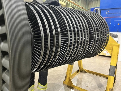
Coppus steam turbines are designed primarily for industrial mechanical drive service, where reliability, simplicity, and adaptability matter more than extreme efficiency. One of the most important design options within the Coppus product range is the choice between single-stage and multistage turbines. This distinction affects performance, size, control behavior, maintenance, and how the turbine fits into a plant’s steam system.
Single-Stage Coppus Steam Turbines
Single-stage Coppus turbines use one set of stationary nozzles and one row of moving blades to extract energy from the steam. Most single-stage designs are impulse turbines, where the steam expands almost entirely in the nozzles before striking the rotor blades. This results in a compact, straightforward machine with relatively few internal components.
These turbines are commonly selected for applications with high inlet steam pressure and moderate power requirements. Because the full pressure drop occurs across a single stage, single-stage turbines are well suited to back-pressure service where the exhaust pressure must remain above a certain level for process use. They are frequently used to drive pumps, fans, and smaller compressors in refineries, chemical plants, and utility systems.
One of the main advantages of single-stage Coppus turbines is mechanical simplicity. Fewer blades, nozzles, and internal clearances mean easier inspection and maintenance. Startup behavior is predictable, and the turbine can tolerate variations in steam quality and operating conditions. This makes single-stage units especially attractive in plants with limited maintenance resources or variable steam supply.
However, because all the energy extraction happens in one step, single-stage turbines have practical limits on power output and efficiency. Blade loading and rotational speed must be kept within conservative limits to ensure long service life. For higher power demands or larger pressure drops, a single-stage design may become inefficient or mechanically impractical.
Multistage Coppus Steam Turbines
Multistage Coppus turbines divide the total steam pressure drop across two or more stages, each consisting of nozzles and blade rows. By extracting energy gradually, multistage designs can handle larger power outputs and wider operating ranges while maintaining acceptable efficiency and blade stress levels.
In industrial service, multistage Coppus turbines are often used where steam conditions or power requirements exceed the comfortable range of a single-stage unit. They are common in condensing applications, where the steam expands to very low exhaust pressures, and in high-horsepower compressor drives. Multistaging allows the turbine to recover more energy without excessive speed or blade loading.
The tradeoff for improved performance is increased complexity. Multistage turbines have more internal components, tighter clearances, and greater sensitivity to alignment and thermal expansion. Maintenance and inspection may require more time and expertise. However, Coppus designs tend to keep staging to a practical minimum, avoiding unnecessary complexity while still meeting performance needs.
Performance and Control Differences
Single-stage turbines respond quickly to changes in steam flow, which can be an advantage in variable-load applications. Their governors are typically simple and robust, making speed control straightforward. Multistage turbines often provide smoother power delivery across a broader load range, but their response to rapid load changes may be more gradual.
From a control standpoint, single-stage turbines are often easier to integrate into basic mechanical drive systems. Multistage turbines may require more careful tuning of governors and protection systems, especially in high-power or condensing service.
Selection Considerations
Choosing between single-stage and multistage Coppus turbines depends on several factors, including inlet and exhaust steam conditions, required power output, speed requirements, and desired efficiency. Plants with moderate power needs and strong emphasis on simplicity often favor single-stage designs. Facilities requiring higher output, better efficiency, or deep steam expansion typically select multistage turbines.
Both options reflect Coppus’s industrial design philosophy. Whether single-stage or multistage, the turbines are built to operate reliably in demanding environments, integrate smoothly with plant steam systems, and deliver long-term value. The choice of staging is not about maximizing technical sophistication, but about matching the turbine design to real-world industrial needs.
Going further, the difference between single-stage and multistage Coppus steam turbines becomes even clearer when viewed through operating behavior, lifecycle costs, and how plants actually use these machines over time.
Operating Behavior in Practice
Single-stage Coppus turbines tend to feel more direct in operation. Changes in steam admission produce an immediate change in speed or torque because there is only one energy extraction step. Operators often describe these turbines as responsive and predictable. This makes them well suited for services where quick reaction matters, such as variable-load pumps or fans.
Multistage turbines behave in a more damped and stable manner. Because energy is extracted across multiple stages, changes in steam flow are distributed through the turbine. This results in smoother torque delivery and better stability at higher power levels. In compressor service or generator drives, this smoother behavior can reduce mechanical stress and vibration.
Steam Conditions and Flexibility
Single-stage turbines are most comfortable with relatively high inlet pressures and modest pressure drops. If steam conditions change significantly, performance can be affected, but the turbine will usually continue to operate safely. Their tolerance for wet or slightly contaminated steam is another practical advantage in older or less controlled steam systems.
Multistage turbines are better suited to wider pressure ranges and deeper expansions. They can extract useful energy even when exhaust pressure is very low, which is why they are commonly used in condensing service. However, they are generally more sensitive to steam quality. Moisture content, in particular, must be managed carefully to avoid blade erosion in later stages.
Maintenance and Inspection Implications
Maintenance differences are significant over the life of the turbine. Single-stage Coppus turbines have fewer parts to inspect and replace. Overhauls are typically shorter and less costly, and many plants can perform routine maintenance with in-house personnel.
Multistage turbines require more detailed inspections. Each stage introduces additional blades, nozzles, and sealing surfaces that must be checked for wear, erosion, or misalignment. While Coppus designs aim to keep maintenance practical, the increased complexity still results in higher inspection effort and longer outage times.
Lifecycle Cost Perspective
From a lifecycle cost standpoint, single-stage turbines often have lower total ownership costs when their power output meets plant needs. Their lower purchase price, simpler installation, and reduced maintenance requirements make them economically attractive for many applications.
Multistage turbines may cost more initially and require more maintenance, but they can deliver greater power and improved steam utilization. In applications where energy recovery is critical or where electric power replacement provides large savings, the higher lifecycle cost can be justified.
Role in Plant Standardization
Many industrial plants standardize on single-stage Coppus turbines wherever possible. This simplifies spare parts inventory, operator training, and maintenance procedures. Multistage turbines are then reserved for applications where single-stage designs are clearly insufficient.
This standardization strategy reinforces the practical classification of Coppus turbines. Single-stage units are treated as general-purpose industrial drives. Multistage units are treated as higher-capacity or special-duty machines.
Long-Term Use and Upgrades
Over time, changes in plant operation can shift how a turbine is viewed. A single-stage turbine may continue operating reliably long after newer technologies are available, simply because it meets the need with minimal trouble. Multistage turbines may be evaluated more frequently for upgrades, especially if improvements in efficiency or control technology offer economic benefits.
Practical Summary
In practical industrial terms, single-stage Coppus steam turbines emphasize simplicity, responsiveness, and low maintenance. Multistage Coppus turbines emphasize higher power capability, smoother operation, and better energy extraction from steam. Both designs reflect the same underlying philosophy: match the turbine to the job, keep the design conservative, and prioritize long-term reliability over theoretical efficiency gains.
Understanding these differences allows engineers and operators to choose the appropriate Coppus turbine configuration and to manage it effectively throughout its service life.
At the last level of detail, single-stage and multistage Coppus steam turbines can be compared by how they influence long-term operating habits, future flexibility, and risk management in industrial plants.
Influence on Operating Habits
Single-stage Coppus turbines tend to fade into the background of daily operations. Once set up and tuned, they often run at a steady speed with minimal adjustment. Operators focus more on the driven equipment and the steam system than on the turbine itself. This low operational footprint is a major reason plants continue to favor single-stage designs wherever possible.
Multistage turbines remain more visible in operations. Their higher power output and closer link to steam conditions mean that operators monitor performance more closely. Changes in load, steam quality, or condenser performance can have a noticeable impact on turbine behavior. This encourages more active engagement with turbine operation and performance tracking.
Future Flexibility and Reuse
Single-stage turbines offer limited but useful flexibility. Minor changes in steam pressure or load can often be accommodated through governor adjustment or nozzle changes. Because the design is simple, repurposing a single-stage turbine for a slightly different application is sometimes practical.
Multistage turbines provide greater performance flexibility but less freedom for repurposing. Their staging is closely matched to specific steam conditions and power requirements. Significant changes in application often require engineering review or hardware modification. As a result, multistage turbines are usually specified with a clearer long-term role in mind.
Risk and Reliability Management
From a risk perspective, single-stage turbines present fewer potential failure points. With fewer stages and components, there are fewer opportunities for erosion, fouling, or alignment issues. This makes them easier to manage in plants with limited maintenance resources or less consistent steam quality.
Multistage turbines carry higher complexity risk but are still highly reliable when properly maintained. Plants that rely on multistage Coppus turbines typically invest more in monitoring, inspection, and preventive maintenance. This tradeoff is accepted because of the higher power output and energy recovery they provide.
Decision-Making in Practice
In real-world decision-making, the choice between single-stage and multistage Coppus turbines often comes down to a simple question: does a single stage do the job? If the answer is yes, plants usually choose the simpler option. If higher power, deeper expansion, or smoother torque delivery is required, multistage designs become necessary.
This practical mindset reflects Coppus’s long-standing role in industrial steam systems. The company’s turbine options are not meant to push technical limits, but to provide dependable solutions that match actual plant needs.
Final Wrap-Up
Single-stage and multistage Coppus steam turbines represent two ends of a practical design spectrum. Single-stage units deliver simplicity, ease of maintenance, and reliable performance for moderate power needs. Multistage units deliver higher capacity, improved energy extraction, and smoother operation for demanding applications.
Both options are built around the same core principles of conservative design and industrial durability. Understanding how each behaves over time allows engineers and operators to make informed choices that balance performance, cost, and reliability across the full life of the plant.
At this point, the remaining distinction between single-stage and multistage Coppus steam turbines is best understood in terms of how they support long-term plant philosophy rather than short-term performance targets.
In plants that value predictability above all else, single-stage turbines often become the default choice. Their behavior is easy to understand, their limits are well known, and their failure modes are usually gradual rather than sudden. This predictability simplifies planning. Operators know how the turbine will respond to steam changes. Maintenance teams know what parts wear and how long overhauls typically take. Management knows that the machine will likely still be running years beyond its original design life. Over time, this builds confidence and reduces the perceived risk of continued operation.
Multistage turbines, while still conservative by industrial standards, introduce a more performance-oriented mindset. Their ability to handle higher power levels and deeper steam expansion means they are often installed where energy recovery or production capacity has a direct financial impact. Because of this, their performance is tracked more closely. Efficiency trends, vibration levels, and steam conditions are reviewed with greater attention. This does not imply fragility, but it does mean the turbine is more closely tied to business outcomes.
Another subtle but important difference lies in how these turbines age. Single-stage turbines tend to age uniformly. Wear is concentrated in predictable areas such as bearings, seals, and nozzle edges. When refurbished, they often return to near-original performance. Multistage turbines age more unevenly. Later stages may see more moisture-related wear, while early stages remain relatively intact. This makes condition-based maintenance more valuable and reinforces the need for periodic internal inspection.
From a modernization perspective, single-stage turbines are often left untouched unless a major process change occurs. Their simplicity makes incremental upgrades less compelling. Multistage turbines, on the other hand, are more likely to be evaluated for control upgrades, improved sealing, or efficiency improvements as part of broader plant optimization projects. Their higher energy throughput makes even small improvements meaningful.
There is also a cultural element. In plants with a long history of steam-driven equipment, single-stage turbines often represent continuity. They are familiar machines, understood across generations of operators and mechanics. Multistage turbines tend to represent investment and intent, signaling that the plant is actively extracting value from its steam system rather than simply managing it.
Taken together, these differences reinforce why Coppus continues to offer both single-stage and multistage options. They are not competing designs but complementary tools. Single-stage turbines provide stability, simplicity, and low ownership burden. Multistage turbines provide capability, flexibility, and improved energy utilization where the application demands it.
In the end, the choice is less about technology and more about fit. Coppus steam turbines succeed because they align turbine complexity with actual industrial needs. By offering both single-stage and multistage designs within the same conservative, industrial framework, Coppus allows plants to choose the level of performance they need without sacrificing reliability or long-term value.
Coppus Steam Turbines for Mechanical Drive Applications
Coppus steam turbines are purpose-built machines for industrial mechanical drive service. Unlike large utility turbines designed mainly for power generation, Coppus turbines are intended to directly drive rotating equipment such as pumps, fans, blowers, compressors, and generators. Their value lies in reliability, simplicity, and the ability to operate continuously in demanding plant environments where steam is already part of the process.
Core Mechanical Drive Concept
In a mechanical drive application, the turbine converts steam energy directly into shaft power without intermediate electrical conversion. This allows high-pressure steam to be used efficiently at the point where mechanical work is needed. Coppus turbines are typically impulse-type designs, meaning steam expands through stationary nozzles before striking the rotor blades. This approach produces high torque at practical speeds and keeps internal construction straightforward.
Most Coppus mechanical drive turbines are designed for direct coupling to the driven equipment. Direct drive reduces mechanical losses, eliminates gearboxes in many cases, and simplifies alignment and maintenance. Where speed matching is required, Coppus designs can accommodate reduction gearing or flexible couplings, but the preference is always toward the simplest workable arrangement.
Typical Mechanical Drive Applications
Coppus turbines are commonly used to drive:
- Boiler feed pumps and process pumps
- Forced-draft and induced-draft fans
- Blowers and large ventilation systems
- Air, gas, and refrigeration compressors
- Small to medium generators for plant power
In these roles, the turbine must deliver steady torque, tolerate load changes, and respond predictably to steam flow adjustments. Coppus designs emphasize these qualities over maximizing peak efficiency.
Steam System Integration
One of the defining advantages of Coppus turbines in mechanical drive service is how well they integrate with industrial steam systems. Many units operate as back-pressure turbines, exhausting steam at a pressure suitable for downstream process use. This allows the turbine to replace a pressure-reducing valve while producing useful shaft power.
Condensing Coppus turbines are also used where higher power output is required or where exhaust steam cannot be reused. These turbines expand steam to low pressure, extracting more energy but requiring additional systems such as condensers and cooling water.
In both cases, the turbine becomes part of the plant’s energy management strategy rather than a standalone machine.
Control and Governing for Mechanical Drives
Speed control is critical in mechanical drive applications. Coppus turbines use mechanical or hydraulic governors to regulate steam admission and maintain stable speed under changing load. For pump and fan drives, the governor is often tuned for smooth, gradual response. For compressor drives, tighter control is required to avoid surge or mechanical stress.
Overspeed protection is a key safety feature. Coppus turbines typically include mechanical overspeed trips that shut off steam quickly if speed exceeds safe limits. This is especially important in mechanical drives, where sudden load loss can occur.
Reliability and Maintenance
Coppus turbines are designed for long service life with minimal intervention. Conservative blade loading, robust casings, and simple internal layouts reduce wear and fatigue. Bearings and seals are sized for continuous operation, and lubrication systems are matched to the duty of the application.
Maintenance is typically straightforward. Many inspections and repairs can be performed on-site, and spare parts strategies are simplified by standardized designs. This makes Coppus turbines well suited to plants that rely on in-house maintenance teams.
Why Coppus for Mechanical Drives
The continued use of Coppus steam turbines in mechanical drive applications is driven by practical benefits. They make use of available steam, reduce electrical demand, and operate reliably in environments where uptime matters more than theoretical efficiency gains. Their designs are tolerant of variable steam conditions and frequent load changes, which are common in industrial settings.
In mechanical drive service, Coppus turbines function as dependable workhorses. They convert steam energy directly into useful motion, integrate smoothly with plant systems, and deliver long-term value through durability and adaptability. For industries that rely on steam and rotating equipment, Coppus steam turbines remain a proven and practical solution.
Looking beyond the basic description, Coppus steam turbines used for mechanical drive applications can be better understood by examining how they influence plant design choices, daily operations, and long-term performance.
Role in Plant Design and Layout
When a Coppus turbine is selected as a mechanical drive, it often shapes the layout of the surrounding equipment. Because the turbine is compact and capable of direct coupling, it can be placed close to the driven machine, reducing shaft length and alignment complexity. This is especially valuable in retrofit projects where space is limited and existing foundations must be reused.
Steam piping is usually simpler as well. In back-pressure applications, the turbine becomes a functional part of the pressure-reduction scheme, which can eliminate or downsize pressure-reducing valves. This not only saves energy but also reduces noise and maintenance associated with throttling devices.
Operational Behavior in Mechanical Drive Service
In daily operation, Coppus mechanical drive turbines are valued for their predictable behavior. Speed changes follow steam valve movement smoothly, without abrupt jumps. This is important for pumps and fans, where sudden speed changes can upset process conditions or cause mechanical stress.
Load sharing is another practical consideration. In some plants, a Coppus turbine-driven machine operates alongside electrically driven equipment. The turbine can be adjusted to carry a base load, with electric motors handling peaks or standby duty. This flexibility allows operators to balance steam use and electrical consumption based on availability and cost.
Startup, Shutdown, and Standby Use
Coppus turbines are well suited to frequent starts and stops, which are common in mechanical drive applications. Their impulse design and conservative clearances reduce the risk of rubbing during thermal expansion. Startup procedures are typically straightforward, involving controlled steam admission and gradual acceleration.
In standby service, Coppus turbines can remain idle for extended periods and still start reliably when needed. This makes them attractive for critical services where backup drive capability is required, such as emergency pumps or essential ventilation fans.
Integration with Maintenance Practices
Mechanical drive turbines from Coppus fit well into preventive maintenance programs. Routine tasks such as oil checks, governor inspection, and overspeed trip testing are easily scheduled and performed. Because the designs are familiar and well documented, troubleshooting is usually direct.
Overhauls tend to focus on wear components rather than major structural repairs. Bearings, seals, and nozzle edges are inspected or replaced as needed, while the core rotor and casing often remain in service for decades.
Long-Term Value in Mechanical Drive Roles
Over the life of a plant, Coppus steam turbines often prove their worth by reducing reliance on electrical infrastructure. They allow plants to use steam energy directly, which can lower demand charges, improve energy resilience, and support operation during electrical outages.
Their durability also supports long-term planning. Many plants continue to operate Coppus mechanical drive turbines long after similar electric drives would have been replaced or upgraded. This longevity reflects the conservative design philosophy behind these machines.
Practical Perspective
In mechanical drive applications, Coppus steam turbines are not chosen because they are the most advanced or the most efficient machines available. They are chosen because they work reliably, fit naturally into steam-based plants, and deliver consistent mechanical power with minimal complexity.
This practical focus explains their continued use across industries such as refining, chemicals, pulp and paper, food processing, and utilities. For these applications, Coppus steam turbines remain a dependable solution for mechanical drive service where long-term reliability and integration with steam systems matter most.
To round out the discussion, Coppus steam turbines for mechanical drive applications can be viewed in terms of how they support resilience, operational independence, and long-term continuity in industrial plants.
Contribution to Operational Resilience
One of the less obvious advantages of Coppus mechanical drive turbines is the resilience they provide. Because they rely on steam rather than electricity, they can continue to operate during electrical disturbances or outages, provided steam supply is maintained. This capability is especially valuable for critical equipment such as boiler feed pumps, emergency cooling pumps, and essential ventilation fans.
In plants where continuous operation is critical, Coppus turbines are often part of a broader resilience strategy. They provide an alternative power path that reduces dependence on the electrical grid and adds a layer of redundancy to key systems.
Energy Independence and Control
Mechanical drive turbines also give plants greater control over how energy is used. Instead of converting steam to electricity and then back to mechanical power through motors, Coppus turbines deliver power directly where it is needed. This direct use reduces conversion losses and simplifies energy flow.
In facilities with fluctuating energy costs, operators can adjust turbine operation to take advantage of available steam, reducing purchased electricity when it is expensive or constrained. This flexibility supports more informed energy management decisions.
Longevity and Institutional Knowledge
Coppus turbines often become long-term fixtures in a plant. As a result, they benefit from accumulated institutional knowledge. Operators and maintenance personnel develop a deep understanding of their behavior, normal operating ranges, and early warning signs of trouble. This familiarity contributes to safe operation and efficient maintenance.
Over time, this institutional knowledge becomes part of the plant’s operational culture. New staff are trained on equipment that has a long track record, reinforcing continuity and reducing the learning curve.
Compatibility with Incremental Upgrades
Another advantage of Coppus mechanical drive turbines is their compatibility with incremental upgrades. While the core turbine design remains unchanged, auxiliary systems such as lubrication, monitoring, or controls can be modernized. This allows plants to improve reliability or integrate digital monitoring without replacing the turbine itself.
This upgrade flexibility supports long-term asset management strategies, allowing plants to extend service life while adopting newer maintenance and monitoring practices.
Final Reflection
Coppus steam turbines for mechanical drive applications occupy a unique position in industrial plants. They are not just machines that produce shaft power; they are tools that support resilience, efficiency, and continuity. Their ability to operate independently of electrical systems, integrate smoothly with steam networks, and deliver reliable performance over decades makes them valuable assets in steam-based industries.
In a landscape where technologies change rapidly, Coppus mechanical drive turbines endure because they address fundamental industrial needs with straightforward, proven designs. This enduring relevance is the strongest testament to their role in mechanical drive applications.
At the deepest level, Coppus steam turbines for mechanical drive applications are best understood as enablers of stable, low-risk industrial operation rather than as performance-driven machines.
In many plants, the original decision to install a Coppus turbine was not based on achieving the highest efficiency or the most advanced control. It was based on the need for something that would run every day, tolerate imperfect conditions, and remain understandable to the people who operate and maintain it. Over time, this original intent becomes even more important. As plants age, staffing changes, and systems are modified, equipment that is simple and predictable becomes increasingly valuable.
Mechanical drive Coppus turbines also influence how plants approach redundancy. Instead of relying solely on electrical systems, plants with steam turbines have a parallel mechanical energy path. This reduces single-point failures. For example, a steam-driven pump can continue to operate even if a motor-driven counterpart is unavailable. This diversity in energy sources strengthens overall system reliability.
Another long-term benefit lies in how Coppus turbines handle uncertainty. Steam pressure may fluctuate, loads may vary, and operating schedules may change. The impulse design, conservative speeds, and robust construction allow these turbines to absorb such variability without demanding constant adjustment. In practical terms, they forgive small mistakes and tolerate less-than-ideal conditions, which is critical in complex industrial environments.
From an asset management perspective, Coppus mechanical drive turbines often outlive the systems around them. Pumps, fans, compressors, and controls may be replaced or upgraded several times while the turbine itself remains in service. This longevity shifts the turbine’s role from a simple machine to a stable anchor in the plant’s mechanical infrastructure.
There is also a psychological element. Operators trust equipment that behaves consistently. Maintenance teams trust machines that respond well to inspection and repair. Over decades, Coppus turbines earn that trust. This trust reduces operational stress, shortens response time during abnormal events, and supports a culture of steady, disciplined operation.
In the end, Coppus steam turbines for mechanical drive applications persist not because they chase technical extremes, but because they solve industrial problems in a durable, human-centered way. They convert available steam into useful work with minimal complication, support independence from electrical systems, and remain understandable and serviceable long after newer technologies come and go.
That combination of practicality, resilience, and longevity defines their continued role in mechanical drive service and explains why Coppus steam turbines remain embedded in industrial plants that value reliability above all else.
Coppus Steam Turbines and Their Operating Styles
Coppus steam turbines are built for industrial service, where steady operation, predictable behavior, and long life matter more than pushing technical limits. Their “operating style” is shaped by how they interact with steam systems, loads, and plant operators. Rather than being defined by a single mode of operation, Coppus turbines are best understood through a set of practical operating styles that reflect how they are actually used in industrial plants.
Continuous-Duty Operation
One of the most common operating styles for Coppus steam turbines is continuous duty. In this mode, the turbine runs for long periods at a relatively stable speed and load. This is typical in applications such as boiler feed pumps, process pumps, and base-load fans.
In continuous-duty service, the turbine is tuned for smooth, steady performance. Steam admission is adjusted gradually, and thermal conditions remain relatively stable. Coppus turbines perform well in this style because their impulse design and conservative clearances minimize wear during long, uninterrupted runs. Maintenance tends to focus on routine checks rather than frequent adjustments.
Variable-Load Operation
Many Coppus turbines operate under variable load conditions, especially when driving fans, blowers, or certain process pumps. In this operating style, the turbine speed and power output change in response to process demands.
Coppus turbines handle variable load operation through robust governors that adjust steam flow smoothly. The turbine responds predictably to load changes without hunting or instability. This operating style highlights one of the key strengths of Coppus designs: the ability to tolerate frequent changes without loss of reliability.
Back-Pressure Operating Style
In back-pressure operation, the turbine is closely tied to the plant’s steam balance. Steam enters at high pressure and exits at a controlled pressure suitable for downstream use. The turbine’s output is therefore influenced not only by mechanical demand but also by process steam requirements.
In this style, the turbine often acts as both a power source and a pressure control device. Operators pay close attention to exhaust pressure, and turbine load may be adjusted to maintain stable steam conditions. Coppus turbines are well suited to this operating style because of their predictable response and simple control systems.
Condensing Operating Style
In condensing operation, the turbine exhausts steam into a condenser under vacuum. This allows for greater energy extraction and higher power output. The turbine operates more independently of process steam demand, with output largely governed by mechanical load.
This operating style is common in applications with high power requirements or limited need for exhaust steam. Coppus condensing turbines emphasize stable speed control and reliable auxiliary systems, such as lubrication and overspeed protection, to support this more performance-focused mode of operation.
Intermittent and Standby Operation
Some Coppus turbines operate intermittently or serve as standby drives. In these cases, the turbine may remain idle for long periods and then be required to start quickly and operate reliably.
Coppus turbines are well suited to this style because their mechanical simplicity allows them to sit idle without deterioration and still start smoothly when needed. This makes them valuable in emergency or backup applications.
Operator-Centered Operating Style
Across all operating modes, Coppus turbines share an operator-centered style. Controls are straightforward, responses are intuitive, and abnormal behavior is usually gradual rather than sudden. This reduces operator workload and supports safe operation, especially in plants without dedicated turbine specialists.
Summary
Coppus steam turbines do not operate in a single, rigid way. Instead, they adapt to a range of operating styles, including continuous duty, variable load, back-pressure, condensing, and standby service. What unites these styles is a consistent design philosophy focused on stability, predictability, and long-term reliability.
By supporting these practical operating styles, Coppus steam turbines continue to meet the real needs of industrial plants where steam is a core resource and dependable mechanical power is essential.
Expanding on operating styles, Coppus steam turbines can also be understood by how they behave over time, how operators interact with them during abnormal conditions, and how they fit into real industrial rhythms rather than ideal operating curves.
Steady-State, Low-Intervention Style
In many plants, the preferred operating style for a Coppus turbine is steady-state, low-intervention operation. Once the turbine reaches normal speed and load, it is left alone except for routine monitoring. This style is common in pump and base-load fan service.
Coppus turbines support this approach through stable governing and conservative thermal design. They do not require constant trimming or fine adjustments. Small changes in steam pressure or load are absorbed naturally by the machine, allowing operators to focus on the process rather than the turbine.
Load-Following Style
Some Coppus turbines are expected to follow load changes closely, particularly in fan and compressor applications tied to process conditions. In this operating style, the turbine responds repeatedly to speed changes, sometimes many times in a single shift.
Coppus turbines are well suited to this because their impulse design reacts directly to steam flow changes without complex internal feedback. The governor’s behavior is easy to predict, which helps operators avoid overshoot or oscillation. Over time, operators learn how much valve movement produces a given speed change, reinforcing confidence in control.
Steam-Balance–Driven Style
In plants with integrated steam systems, Coppus turbines often operate according to steam balance rather than mechanical demand alone. The turbine load may be increased to reduce pressure on a high-pressure header or decreased to protect a low-pressure system.
This style requires close coordination between turbine operation and boiler control. Coppus turbines fit naturally into this role because they behave like controlled pressure-reducing devices with the added benefit of producing mechanical power. Their stable exhaust characteristics support this dual function.
Independent Power Style
In condensing service, Coppus turbines often operate in a more independent power-focused style. The turbine’s primary role is to deliver shaft power, and exhaust conditions are managed by the condenser system.
In this mode, attention shifts to speed stability, vibration, and lubrication performance. Although this style demands more monitoring, Coppus turbines remain predictable and forgiving compared to more tightly optimized machines.
Abnormal and Transient Operation
Another important operating style involves how Coppus turbines behave during abnormal or transient events. These include sudden load loss, steam pressure disturbances, or rapid shutdowns.
Coppus turbines are designed to handle these events without damage. Overspeed protection acts quickly, casings and rotors tolerate thermal changes, and the machines usually return to service without lasting effects. This resilience is a defining part of their operating style and a key reason for their continued use.
Long-Horizon Operating Style
Finally, Coppus turbines operate on a long horizon. They are not machines that demand frequent redesign or replacement. Their operating style supports decades of service, gradual wear, and predictable aging.
Operators and maintenance teams adapt their practices around this long-term behavior, treating the turbine as a stable element of the plant rather than a constantly evolving system.
Closing Perspective
The operating styles of Coppus steam turbines reflect industrial reality. They support steady operation, load following, steam balance control, independent power production, and reliable response to abnormal conditions. Across all these styles, the common thread is predictability.
This predictability is not accidental. It is the result of conservative design choices that prioritize how machines are actually used. By aligning turbine behavior with operator expectations and plant rhythms, Coppus steam turbines continue to deliver dependable mechanical power across a wide range of industrial operating styles.
At the final layer, Coppus steam turbines and their operating styles can be understood as part of an unwritten agreement between the machine and the plant: the turbine does not demand perfection, and in return it delivers steady, dependable service.
In everyday operation, Coppus turbines rarely call attention to themselves. They do not require constant tuning, software updates, or complex diagnostics. Their operating style is calm and mechanical, driven by valves, governors, and physical feedback rather than digital abstraction. This makes their behavior easy to interpret, even during unusual conditions.
Another defining aspect of their operating style is gradual response. When something changes, load increases, steam pressure drops, or a valve position shifts, the turbine responds in steps rather than spikes. This gives operators time to react and prevents minor disturbances from escalating into major events. Over decades, this quality becomes more valuable than marginal efficiency gains.
Coppus turbines also establish a rhythm within the plant. Operators know when to warm them up, how quickly they will accelerate, and what sounds and vibrations are normal. This familiarity turns the turbine into a known quantity. Abnormal behavior stands out clearly, which improves safety and troubleshooting speed.
Their operating style also supports human judgment. Instead of forcing operators to rely entirely on instruments, Coppus turbines provide physical cues, valve feel, sound, temperature, and speed behavior that experienced operators can interpret intuitively. This reinforces confidence and reduces overreliance on automated systems.
From a management perspective, this operating style reduces risk. Equipment that behaves predictably is easier to plan around. Outages are fewer, failures are rarer, and maintenance can be scheduled rather than reactive. Over time, this stability supports consistent production and lower total ownership cost.
In the end, Coppus steam turbines succeed not because they introduce new operating styles, but because they respect old ones that work. Their designs align with how industrial plants actually run: imperfect steam, changing loads, mixed skill levels, and long service expectations.
This alignment is what defines their operating style. Coppus steam turbines operate steadily, respond predictably, tolerate variability, and age gracefully. That combination explains why they remain trusted mechanical drivers in industrial plants long after newer, more complex technologies have come and gone.
At this stage, the operating styles of Coppus steam turbines can be summed up by how they influence trust, continuity, and decision-making over the full lifespan of an industrial plant.
Coppus turbines operate in a way that builds trust slowly but firmly. They start predictably, run consistently, and give early warning when something is not right. This trust changes how operators and engineers think about risk. Instead of planning around frequent failures or unpredictable behavior, they plan around long service intervals and routine upkeep. The turbine becomes something the plant can rely on, not something it must constantly manage.
Their operating style also supports continuity. Many Coppus turbines remain in service across multiple generations of operators and maintenance personnel. Procedures are passed down, sounds and behaviors are recognized, and the machine’s role in the plant becomes almost institutional. This continuity reduces the operational disruption that often accompanies equipment turnover.
Another key aspect of their operating style is tolerance for human variability. Coppus turbines do not assume perfect operation. Minor timing differences during startup, small variations in steam pressure, or gradual load changes do not immediately translate into damage or trips. This tolerance makes them especially suitable for complex industrial environments where conditions are rarely ideal.
From a strategic standpoint, this operating style influences equipment decisions. Plants that already rely on Coppus turbines are often inclined to keep them, refurbish them, or specify similar designs in new projects. The operating style aligns with long-term thinking rather than short-term optimization.
Finally, Coppus turbines encourage a balanced relationship between automation and human control. While they can be instrumented and monitored, they do not require sophisticated automation to operate safely and effectively. This balance allows plants to modernize at their own pace without becoming dependent on complex control systems.
In conclusion, the operating styles of Coppus steam turbines are defined less by technical modes and more by behavior over time. They operate calmly, predictably, and forgivingly. They support steady industrial rhythms, tolerate imperfection, and reward consistent care with long service life.
That operating style is not incidental. It is the outcome of deliberate design choices aimed at real industrial use. And it is the reason Coppus steam turbines continue to be valued wherever steam is available and reliable mechanical power is required.
Coppus Steam Turbine Types Explained for Industrial Use
Coppus steam turbines are widely used in industrial plants where steam is already part of the energy system. Their designs focus on dependable mechanical power rather than utility-scale electricity generation. For industrial users, understanding the different types of Coppus steam turbines helps in selecting the right machine for a specific application, steam condition, and operating style.
Impulse-Type Coppus Turbines
Nearly all Coppus steam turbines used in industry are impulse turbines. In an impulse design, steam expands through stationary nozzles before striking the moving blades on the rotor. The pressure drop occurs mainly in the nozzles, not across the blades. This makes the turbine mechanically simple, rugged, and well suited to variable steam quality.
Impulse turbines are ideal for industrial environments because they tolerate moisture and small contaminants better than reaction turbines. Coppus impulse designs also allow straightforward governing and predictable speed control, which are important for mechanical drive applications.
Back-Pressure (Non-Condensing) Turbines
Back-pressure Coppus turbines exhaust steam at a pressure above atmospheric pressure so it can be reused in downstream processes. These turbines are common in plants that require large amounts of low- or medium-pressure steam for heating or processing.
In this type, the turbine serves two functions: it produces mechanical power and reduces steam pressure. Back-pressure turbines are typically simple to install and operate because they do not require condensers or vacuum systems. They are widely used to drive pumps, fans, and compressors in refineries, chemical plants, and paper mills.
Condensing Turbines
Condensing Coppus turbines exhaust steam into a condenser at very low pressure. This allows the turbine to extract more energy from the steam and deliver higher power output compared to back-pressure designs.
These turbines are used where maximum power recovery is desired and where exhaust steam is not needed for process use. Condensing turbines are more complex due to the required condenser, cooling water, and vacuum systems, but they provide greater flexibility in power production.
Single-Stage Turbines
Single-stage Coppus turbines use one set of nozzles and one row of blades. They are compact, easy to maintain, and well suited to moderate power requirements. Single-stage designs are commonly used in back-pressure service and in mechanical drives for pumps and fans.
Their simplicity makes them attractive for plants that value low maintenance effort and long service life over peak efficiency.
Multistage Turbines
Multistage Coppus turbines use multiple stages to divide the steam pressure drop across several blade rows. This allows them to handle higher power outputs and deeper steam expansion.
These turbines are often used in condensing service or in high-horsepower compressor drives. While more complex than single-stage designs, multistage turbines offer smoother operation and improved energy recovery where required.
Mechanical Drive Turbines
Many Coppus turbines are specifically designed for mechanical drive service. These turbines are directly coupled to equipment such as pumps, fans, and compressors. Speed control, starting torque, and load response are tailored to the driven machine rather than to electrical grid requirements.
Mechanical drive Coppus turbines emphasize stability, predictable response, and long-term reliability.
Generator Drive Turbines
Some Coppus turbines are configured to drive generators, either for plant power or for auxiliary electrical supply. These turbines require tighter speed control but retain the same impulse-based, industrial design philosophy.
Summary
Coppus steam turbine types for industrial use can be grouped by design principle, exhaust condition, staging, and application. Impulse construction, back-pressure or condensing operation, single-stage or multistage design, and mechanical or generator drive configurations cover most industrial needs.
Across all types, Coppus turbines share common traits: conservative design, tolerance for real-world steam conditions, ease of maintenance, and long service life. These characteristics make them a practical choice for industries that rely on steam and need dependable mechanical power rather than maximum theoretical efficiency.
To complete the picture, it helps to look at Coppus steam turbine types through the lens of how they are selected, applied, and kept in service over long industrial lifecycles.
Selection Based on Steam Availability
In industrial use, the first factor that usually determines the turbine type is steam availability. Plants with excess high-pressure steam and consistent downstream demand often favor back-pressure Coppus turbines. These units allow the plant to recover mechanical energy while still supplying usable steam to processes.
Where steam demand is limited or intermittent, condensing turbines become more attractive. Even though they add complexity, they allow plants to extract maximum energy from steam that would otherwise be throttled or vented. Coppus offers both types so that turbine selection aligns with real steam system constraints rather than idealized efficiency targets.
Matching Turbine Type to Driven Equipment
Another key consideration is the nature of the driven machine. Pumps and fans generally favor single-stage or low-stage turbines because of their modest power requirements and steady operating characteristics. Compressors and large blowers often require multistage turbines to deliver higher horsepower smoothly and reliably.
Coppus turbine types are therefore not chosen in isolation. They are matched to torque characteristics, startup requirements, and speed ranges of the driven equipment. This matching is central to successful industrial operation and long service life.
Simplicity Versus Capability
Industrial users often face a tradeoff between simplicity and capability. Single-stage, back-pressure turbines represent the simplest Coppus designs. They are easy to operate, easy to maintain, and forgiving of operating variations. Multistage, condensing turbines offer greater capability but require more attention to auxiliary systems and operating limits.
Coppus turbine types are structured to allow plants to choose the minimum complexity needed to meet their goals. This approach reduces risk and long-term cost.
Retrofit and Replacement Considerations
Coppus steam turbines are frequently installed as replacements or upgrades for older units. Their standardized designs and conservative operating parameters make them well suited to retrofit projects. Back-pressure turbines often replace pressure-reducing valves, while mechanical drive turbines replace or supplement electric motors.
In these cases, turbine type selection is influenced by existing foundations, piping, and operating practices. Coppus designs are flexible enough to accommodate these constraints without major plant modifications.
Long-Term Service and Support
Regardless of type, Coppus steam turbines are designed for long-term service. Many units remain in operation for several decades. This longevity affects how turbine types are viewed. Plants are less concerned with short-term performance differences and more focused on reliability, spare parts availability, and serviceability.
Single-stage and multistage turbines alike benefit from this design philosophy. Even the more capable condensing units retain conservative mechanical margins that support long service life.
Closing View
When explained for industrial use, Coppus steam turbine types are best understood as practical tools rather than abstract categories. Each type exists to solve a specific industrial problem: pressure reduction, mechanical drive, energy recovery, or power generation.
By offering impulse-based, back-pressure and condensing designs in single-stage and multistage configurations, Coppus provides a complete but restrained lineup. This allows industrial users to select a turbine type that fits their steam system, driven equipment, and operating culture without unnecessary complexity.
That alignment between turbine type and industrial reality is the reason Coppus steam turbines continue to be widely used and respected in industrial applications.
At the broadest level, Coppus steam turbine types for industrial use reflect a philosophy of fitting the machine to the plant, not forcing the plant to adapt to the machine.
Over time, industrial facilities evolve. Steam pressures change, processes are added or removed, and energy strategies shift. Coppus turbine types are flexible enough to remain useful through these changes. A back-pressure turbine installed for one process may later support a different load. A mechanical drive turbine may continue operating even as the driven equipment is upgraded or replaced. This adaptability is a quiet but important advantage.
Another way to view Coppus turbine types is by how they distribute responsibility within the plant. Simple single-stage, back-pressure turbines place much of the control responsibility with the operator. Their behavior is easy to observe and adjust. More complex multistage or condensing turbines shift some responsibility to systems, condensers, vacuum equipment, and protection devices. Coppus designs keep this balance manageable, avoiding unnecessary layers of automation.
There is also a difference in how turbine types influence maintenance culture. Simpler turbines encourage routine, hands-on maintenance and inspection. More capable turbines encourage condition monitoring and planned interventions. Coppus supports both approaches by keeping core components accessible and designs consistent across models.
From a financial perspective, turbine type selection often reflects long-term cost thinking rather than initial purchase price. Back-pressure turbines may justify themselves through reduced throttling losses. Condensing turbines justify themselves through recovered energy. Mechanical drive turbines justify themselves through reduced electrical demand and increased resilience. Coppus turbine types align well with these practical economic drivers.
Perhaps most importantly, Coppus steam turbine types share a common operating temperament. Regardless of size or configuration, they are designed to behave calmly, predictably, and conservatively. This consistency makes it easier for plants to operate different turbine types side by side without introducing new risks or training burdens.
In closing, Coppus steam turbine types for industrial use are not a collection of specialized machines chasing narrow performance goals. They are a family of practical designs built around industrial realities: variable steam, changing loads, long service expectations, and human-centered operation.
That shared foundation is what allows Coppus turbines of many types to coexist in the same plant and continue delivering reliable mechanical power long after their original installation purpose has evolved.
At the final level of understanding, Coppus steam turbine types for industrial use can be seen as part of a long-standing industrial mindset that values durability, adaptability, and restraint.
Unlike many modern machines that are optimized for narrow operating windows, Coppus turbine types are designed with wide margins. This shows up in thicker casings, conservative blade stresses, moderate speeds, and simple governing systems. These features are shared across back-pressure, condensing, single-stage, and multistage designs. The result is a family of turbines that behave similarly even when their configurations differ. For plant personnel, this consistency reduces uncertainty and simplifies training.
Another important aspect is how Coppus turbine types age. Industrial plants rarely replace equipment because it stops working entirely. More often, they replace equipment because it becomes difficult to maintain, difficult to integrate, or poorly matched to current operations. Coppus turbines avoid this fate by remaining serviceable and understandable long after installation. Even when process demands change, the turbine often continues to make sense in its role.
This is especially clear in plants that modernize their electrical systems while retaining steam turbines for mechanical drives. Electrical infrastructure may become more complex over time, but the Coppus turbine remains mechanically straightforward. Its type, whether back-pressure or condensing, single-stage or multistage, continues to align with the physical reality of steam and rotating equipment.
Coppus turbine types also influence how plants think about energy recovery. Rather than treating steam pressure reduction or excess steam as a loss, these turbines turn it into useful work. This mindset is deeply industrial. It focuses on extracting value from what already exists rather than adding layers of new technology. Back-pressure turbines, in particular, embody this approach by converting necessary pressure drops into mechanical output.
In long-running facilities, Coppus turbine types often become reference points. Operators compare newer equipment to them. Maintenance strategies are built around them. When problems occur elsewhere in the plant, these turbines are rarely the cause. This quiet reliability reinforces their reputation and justifies continued investment in similar designs.
Ultimately, Coppus steam turbine types are not defined only by technical categories. They are defined by how they behave over decades of real operation. They start reliably, run steadily, tolerate imperfect conditions, and respond predictably. Whether simple or more capable, they reflect a deliberate choice to prioritize industrial stability over theoretical optimization.
That choice explains why Coppus steam turbines remain relevant in industrial use. Their types cover a wide range of needs, but they all share the same underlying purpose: to provide dependable mechanical power using steam, in a way that fits naturally into industrial life and continues to make sense year after year.
Coppus Steam Turbine Models and Configurations
Coppus steam turbine models and configurations are built around a simple idea: offer enough variation to meet real industrial needs without introducing unnecessary complexity. Rather than an overwhelming catalog of highly specialized machines, Coppus provides a structured range of models that can be configured to match steam conditions, power requirements, and driven equipment.
Model Families and Size Ranges
Coppus turbine models are generally organized by frame size and power range. Smaller models are intended for low to moderate horsepower applications such as pumps, fans, and auxiliary equipment. Larger models handle higher horsepower duties, including major process compressors and large induced-draft fans.
Each model family shares common design features, including impulse construction, robust casings, and standardized components. This consistency allows plants to operate multiple Coppus turbines of different sizes with similar maintenance practices and operating expectations.
Horizontal and Vertical Configurations
Most Coppus steam turbines are supplied in horizontal configurations. Horizontal mounting simplifies alignment, inspection, and maintenance, making it the preferred choice for most mechanical drive applications.
Vertical configurations are available for specific applications where space constraints or equipment layout make horizontal mounting impractical. Vertical turbines are often used with vertical pumps or where floor space is limited. While the orientation differs, the internal design philosophy remains the same.
Single-Valve and Multi-Valve Arrangements
Coppus turbine models can be configured with single or multiple steam admission valves. Smaller turbines often use a single valve for simplicity and ease of control. Larger turbines may use multiple valves to improve load control, startup behavior, and efficiency across a wider operating range.
Multi-valve configurations allow steam to be admitted in stages, reducing thermal stress during startup and improving control under varying loads. This option is commonly applied in higher horsepower or more demanding applications.
Back-Pressure and Condensing Configurations
Most Coppus models can be supplied as back-pressure or condensing turbines. In back-pressure configurations, the exhaust casing and outlet are designed to deliver steam at a controlled pressure for downstream use. These configurations are common in plants with integrated steam systems.
Condensing configurations include provisions for low-pressure exhaust, condenser connections, and vacuum systems. These turbines extract more energy from steam but require additional auxiliary equipment. Coppus condensing models are typically selected for applications where power recovery is a priority.
Single-Stage and Multistage Models
Single-stage models dominate lower horsepower ranges and applications that prioritize simplicity. These turbines use one nozzle set and one blade row, resulting in compact size and straightforward maintenance.
Multistage models are used when higher power output or deeper steam expansion is required. These configurations distribute the pressure drop across multiple stages, reducing blade stress and improving energy utilization. While more complex internally, they maintain the same conservative mechanical margins as single-stage models.
Mechanical Drive and Generator Drive Configurations
Coppus turbines are commonly configured for mechanical drive service, with shaft ends, bearings, and speed control tailored to the driven equipment. Direct coupling is preferred whenever possible to reduce losses and maintenance.
Generator drive configurations are also available, requiring tighter speed regulation and specific coupling arrangements. These models retain the same impulse-based design but include governing features suitable for electrical generation.
Customization Within Standard Designs
While Coppus turbines are standardized, they allow for meaningful customization. Options include different nozzle arrangements, casing materials, seal designs, lubrication systems, and control packages. These choices allow a standard model to be adapted to specific steam conditions, environments, or operating philosophies.
Importantly, customization does not change the fundamental character of the turbine. Coppus avoids one-off designs that complicate maintenance and long-term support.
Long-Term Consistency
One of the defining features of Coppus turbine models and configurations is continuity. Newer models are designed to align with older ones in terms of operating behavior and service approach. This allows plants to integrate new turbines without reinventing procedures or training programs.
Summary
Coppus steam turbine models and configurations form a practical, well-structured lineup. Horizontal or vertical mounting, single or multivalve admission, back-pressure or condensing exhaust, single-stage or multistage construction, and mechanical or generator drive options cover most industrial needs.
What distinguishes Coppus is not the number of models, but how consistently they are designed. Each configuration reflects the same conservative, industrial philosophy: build turbines that fit real plants, operate predictably, and remain serviceable for decades.
Looking beyond the basic layout of models and configurations, Coppus steam turbines reveal their real value in how those configurations support long-term plant strategy rather than short-term specification targets.
Configuration as a Planning Tool
In many industrial plants, the selected Coppus turbine configuration becomes part of the plant’s long-term planning framework. A back-pressure, single-stage, mechanical drive turbine is often chosen not just for today’s load, but for how it will behave as processes shift and equipment ages. The configuration leaves room for operational flexibility without locking the plant into narrow performance limits.
Multistage or condensing configurations, by contrast, are often selected where future expansion or higher energy recovery is expected. These configurations allow plants to grow into the turbine’s capability rather than immediately pushing it to its limits.
Interchangeability and Familiarity
Another strength of Coppus turbine configurations is the degree of interchangeability. Because model families share common components and design principles, spare parts strategies can be simplified. Bearings, seals, governors, and even internal components often resemble those used in other Coppus models.
This familiarity reduces downtime and training requirements. Maintenance teams can work confidently across different configurations without needing specialized knowledge for each machine.
Influence on Maintenance Philosophy
Configuration choice also shapes maintenance practices. Simpler configurations encourage hands-on, interval-based maintenance. More capable configurations may justify condition monitoring and periodic performance reviews.
Coppus turbines support both approaches without forcing complexity. Even multistage, condensing models are designed so that internal inspection and repair remain manageable with standard tools and procedures.
Retrofit-Friendly Configurations
Many Coppus models are selected specifically because they are retrofit-friendly. Their configurations can often be adapted to existing foundations, piping layouts, and coupling arrangements. This is especially important when replacing older turbines or converting from electric drives.
Back-pressure configurations, in particular, are frequently installed as replacements for pressure-reducing valves, allowing plants to recover energy without major system redesign.
Configuration Stability Over Time
Unlike rapidly evolving technologies, Coppus turbine configurations remain stable over long periods. This stability supports long-term support, spare parts availability, and institutional knowledge. Plants can invest in a Coppus turbine with confidence that its configuration will not become obsolete quickly.
Even as control and monitoring technologies evolve, the core turbine configuration remains valid. Upgrades tend to focus on auxiliaries rather than the turbine itself.
Final Perspective
Coppus steam turbine models and configurations are not about offering endless options. They are about offering the right options, structured in a way that aligns with industrial reality. Each configuration represents a deliberate balance between simplicity, capability, and longevity.
By maintaining consistency across models while allowing practical customization, Coppus enables industrial plants to select turbines that fit their operational culture and long-term goals. That balance is what keeps Coppus steam turbines relevant and trusted across decades of industrial use.
At the deepest level, Coppus steam turbine models and configurations represent a disciplined approach to industrial machinery design, where restraint is as important as capability.
Each configuration exists because it has proven useful in real plants over long periods of time. Coppus does not introduce new model variations to chase marginal gains or short-term trends. Instead, configurations are refined slowly, preserving compatibility with earlier designs. This approach protects plant investments and avoids forcing changes in operating or maintenance culture.
Another defining feature is how Coppus configurations manage risk. Simpler models reduce the number of failure points and limit the consequences of abnormal conditions. More capable configurations add complexity only where the value is clear, such as higher power recovery or broader operating range. In all cases, safety margins are maintained, and operating behavior remains predictable.
Coppus configurations also support phased decision-making. Plants can start with a simpler back-pressure or single-stage model and later move to more capable configurations as needs evolve. Because the operating style and maintenance approach remain familiar, these transitions are manageable and low risk.
There is also a strong alignment between Coppus configurations and human factors. Controls, access points, and maintenance features are designed to be intuitive. Even as configurations become more complex internally, external interaction remains straightforward. This reduces training burden and supports safe operation over long service lives.
Over time, Coppus steam turbine models often become reference assets within a plant. Their configurations influence how new equipment is specified and evaluated. Other machines are expected to meet the same standards of predictability and serviceability. This sets a baseline for plant reliability and performance.
In closing, Coppus steam turbine models and configurations are not defined by novelty or variety for its own sake. They are defined by continuity, practicality, and respect for industrial realities. Each model and configuration fits into a broader system designed to deliver dependable mechanical power with minimal disruption over decades.
That long view is what distinguishes Coppus turbines. Their models and configurations remain relevant not because they change often, but because they were designed from the start to endure.
At the final point of this discussion, Coppus steam turbine models and configurations can be understood as part of an industrial legacy rather than a product lineup in the modern marketing sense.
In many plants, Coppus turbines are among the oldest pieces of rotating equipment still in daily service. Their model designations and configurations may have been selected decades ago, yet they continue to fit current operating needs. This longevity is not accidental. It reflects design decisions that favored mechanical clarity, material durability, and operating forgiveness over tight optimization.
One of the quiet strengths of Coppus configurations is that they age in a predictable way. Wear occurs where it is expected, performance declines gradually, and corrective actions are well understood. This predictability allows plants to plan refurbishments instead of reacting to failures. Over time, this lowers risk and stabilizes maintenance budgets.
Coppus configurations also encourage conservative operation. Because the turbines are not optimized to the edge of their capability, operators rarely feel pressure to push them beyond comfortable limits. This reduces stress on both the machine and the people responsible for it. The turbine becomes a steady contributor rather than a source of concern.
From a systems perspective, Coppus turbine models often act as anchors in plant energy and mechanical systems. Steam headers, pressure levels, and equipment layouts may evolve around them. This anchoring effect reinforces the value of choosing configurations that will remain relevant over decades.
Even when plants modernize controls, instrumentation, or monitoring systems, the core Coppus turbine configuration remains unchanged. This separation of mechanical reliability from technological change allows plants to adopt new tools without risking the stability of critical equipment.
Ultimately, Coppus steam turbine models and configurations persist because they align with how industrial plants actually operate over long time horizons. They support gradual change, tolerate imperfect conditions, and reward steady care with long service life.
That enduring alignment, more than any specific feature or option, explains why Coppus steam turbine models and configurations continue to be specified, maintained, and trusted in industrial facilities around the world.
Coppus Steam Turbines: Types, Applications, and Key Features
Coppus steam turbines are industrial machines designed to convert steam energy into dependable mechanical power. They are widely used in plants where steam is already available and where reliability, simplicity, and long service life are more important than pushing efficiency limits. Understanding their types, typical applications, and defining features helps explain why they remain common in industrial settings.
Types of Coppus Steam Turbines
Coppus turbines are primarily impulse-type machines. Steam expands through stationary nozzles and transfers energy to the rotor blades by momentum rather than by pressure drop across the blades. This approach keeps internal design simple and tolerant of real-world steam conditions.
They are commonly classified by exhaust condition:
- Back-pressure (non-condensing) turbines, which exhaust steam at a usable pressure for downstream processes.
- Condensing turbines, which exhaust steam into a condenser under vacuum to extract more energy and produce higher power output.
They are also classified by staging:
- Single-stage turbines, used for lower power applications where simplicity and ease of maintenance are priorities.
- Multistage turbines, used where higher power or deeper steam expansion is required.
Applications in Industrial Plants
Coppus steam turbines are primarily used for mechanical drive applications. Common uses include driving pumps, fans, blowers, compressors, and occasionally generators. In many plants, they replace or supplement electric motors, especially where steam pressure reduction is already necessary.
Back-pressure turbines are often installed where process steam is required after pressure reduction. Condensing turbines are selected where steam demand is limited but power recovery is valuable.
Industries that commonly use Coppus turbines include refining, chemical processing, pulp and paper, food processing, power generation auxiliaries, and utilities.
Key Features and Design Characteristics
The defining feature of Coppus steam turbines is conservative industrial design. Casings are robust, blade loading is modest, and operating speeds are kept within comfortable limits. This reduces mechanical stress and supports long service life.
Speed control is handled through mechanical or hydraulic governors that provide smooth, predictable response to load changes. Overspeed protection is a standard feature, ensuring safe operation during sudden load loss.
Coppus turbines are designed for direct coupling to driven equipment, minimizing mechanical losses and simplifying maintenance. Lubrication systems, bearings, and seals are sized for continuous duty and long operating intervals.
Another key feature is tolerance. Coppus turbines handle variable steam pressure, moisture, and frequent starts without requiring constant adjustment. This makes them well suited to industrial environments where conditions are rarely ideal.
Operational and Maintenance Benefits
From an operational standpoint, Coppus turbines are easy to start, stable in operation, and forgiving of minor deviations. Operators can quickly learn their behavior, and abnormal conditions tend to develop gradually rather than suddenly.
Maintenance is straightforward. Most work focuses on wear components such as bearings, seals, and nozzle edges. Internal access is practical, and parts availability supports long-term service.
Summary
Coppus steam turbines are defined by their practicality. Their types cover back-pressure and condensing service, single-stage and multistage construction, and mechanical or generator drive configurations. Their applications center on industrial mechanical drives where steam is available and reliability is critical.
Key features include impulse design, conservative mechanical margins, predictable control, and long service life. Together, these characteristics explain why Coppus steam turbines continue to play a vital role in industrial plants that value dependable performance over decades of operation.
To fully round out the topic, it helps to step back and look at how Coppus steam turbines fit into the broader industrial picture when considering their types, applications, and key features together.
How Types Influence Application Choices
In real plants, Coppus turbine types are rarely chosen in isolation. A back-pressure, single-stage turbine might be selected not because it is the most efficient option, but because it fits seamlessly into an existing steam header and can drive a pump without changing downstream pressure requirements. A multistage, condensing turbine might be chosen where energy recovery justifies additional complexity.
This practical alignment between turbine type and plant reality is a defining strength. Coppus designs do not force a plant to reorganize around the turbine. Instead, the turbine is shaped to match what already exists.
Key Features That Support Industrial Use
The features that matter most in industrial service are not always those highlighted in performance charts. Coppus turbines emphasize features that reduce risk and operational burden. These include robust casings, conservative blade design, simple governing systems, and accessible internals.
Overspeed protection, reliable lubrication, and predictable startup behavior are considered baseline requirements rather than optional enhancements. These features protect both equipment and personnel, especially in mechanical drive applications where sudden load changes can occur.
Integration with Steam and Energy Systems
Coppus steam turbines integrate naturally with industrial steam systems. Back-pressure turbines turn necessary pressure reduction into useful work. Condensing turbines allow excess steam energy to be recovered when process demand is low.
In both cases, the turbine becomes part of the plant’s energy management strategy. It helps balance steam flows, reduce electrical demand, and improve overall energy utilization without introducing fragile or highly optimized systems.
Human Factors and Operating Culture
Another key feature, though less tangible, is how Coppus turbines align with human operation. Controls are straightforward, behavior is consistent, and responses are gradual. This supports safe operation in plants where operators manage many systems simultaneously.
Because Coppus turbines are forgiving of small errors and variations, they reduce stress on operating staff and lower the likelihood of serious incidents. Over time, this human-centered design contributes to reliable, repeatable operation.
Long-Term Value and Reliability
Across decades of service, Coppus steam turbines demonstrate value through longevity rather than headline efficiency. Many units remain in operation long after installation, with periodic refurbishment keeping them productive.
This long-term reliability supports capital planning. Plants can invest in a Coppus turbine knowing it will remain relevant as processes evolve and supporting systems change.
Final Perspective
When viewed as a whole, Coppus steam turbines are best defined by how well their types, applications, and key features work together. They are not machines designed to impress on paper. They are machines designed to work quietly and reliably in demanding industrial environments.
That focus on practical performance, integration with steam systems, and long service life explains why Coppus steam turbines continue to be specified and trusted wherever dependable mechanical power from steam is needed.
At the deepest level, Coppus steam turbines stand out because they represent a complete industrial solution rather than a collection of isolated technical features.
Their types exist to match real steam systems, not ideal ones. Back-pressure turbines accept the reality that pressure reduction is unavoidable in steam plants and turn it into useful work. Condensing turbines acknowledge that excess steam energy has value even when process demand is low. Single-stage and multistage designs exist not to create product variety, but to scale capability without changing the underlying operating philosophy.
Their applications reflect how industry actually functions. Pumps must run every day. Fans must respond to changing conditions. Compressors must deliver steady output without drama. Coppus turbines are applied where failure is costly and interruptions ripple through an entire plant. That is why they are found in services that matter most, boiler feed, critical process pumps, major ventilation systems, and large compressors.
Their key features reinforce this purpose. Conservative speeds reduce wear. Impulse construction tolerates wet or imperfect steam. Mechanical governors provide control that operators understand and trust. Overspeed protection is direct and decisive. Maintenance access is practical rather than elegant. None of these features exist to impress. They exist to keep the turbine running.
Over time, these elements create a feedback loop. Reliable operation builds operator confidence. Confidence leads to consistent care. Consistent care extends service life. Long service life reinforces the decision to use similar machines in future projects. In many plants, this cycle has repeated for decades.
Another important aspect is how Coppus turbines coexist with newer technology. Plants may add digital monitoring, automated controls, or advanced analytics, but the turbine itself does not depend on them. This separation allows modernization without increasing operational risk. The turbine remains mechanically dependable even as the surrounding systems evolve.
In practical terms, Coppus steam turbines reduce uncertainty. They reduce the chance of sudden failure, the need for specialized expertise, and the pressure to operate within narrow limits. This reduction in uncertainty is often more valuable than incremental efficiency gains, especially in complex industrial environments.
In the end, Coppus steam turbines are defined by balance. They balance energy recovery with simplicity, capability with restraint, and longevity with adaptability. Their types, applications, and key features all point to the same goal: deliver reliable mechanical power from steam in a way that fits industrial reality and continues to make sense year after year.
That balance is why Coppus steam turbines remain trusted workhorses in industry, not as legacy equipment clinging to relevance, but as deliberately designed machines that still solve the problems they were built to address.
At the final conclusion, Coppus steam turbines can be understood as machines shaped by experience rather than theory.
Across their types, applications, and key features, one theme remains constant: they are built to function in environments where conditions are imperfect, priorities change, and equipment must keep running regardless. This perspective explains why Coppus turbines do not chase peak efficiency curves or narrow design points. Instead, they are tuned for steady usefulness across a wide range of operating scenarios.
In industrial plants, value is measured over decades. A turbine that runs reliably for thirty or forty years, integrates smoothly with evolving steam systems, and remains understandable to successive generations of operators delivers far more value than one that performs brilliantly for a short time but demands constant attention. Coppus turbines are designed with this long view in mind.
Their types give plants choices without forcing complexity. Their applications focus on critical mechanical duties rather than optional services. Their key features emphasize protection, predictability, and serviceability. Together, these elements create equipment that fits naturally into industrial life.
Perhaps most importantly, Coppus steam turbines respect the human element of industrial operation. They allow operators to rely on experience and judgment. They provide clear physical feedback. They forgive small errors and signal problems early. This human-centered approach is rare and increasingly valuable in complex plants.
In a changing industrial landscape, Coppus steam turbines remain relevant because they solve enduring problems in an enduring way. They convert steam into dependable mechanical power with minimal complication, integrate with real-world systems, and remain useful long after newer technologies have come and gone.
That is the lasting significance of Coppus steam turbines. Not as cutting-edge machines, but as trusted industrial partners that quietly do their job, day after day, year after year, exactly as they were designed to do.
EMS Power Machines
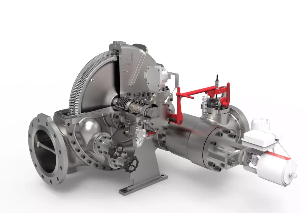
We design, manufacture and assembly Power Machines such as – diesel generators, electric motors, vibration motors, pumps, steam engines and steam turbines
EMS Power Machines is a global power engineering company, one of the five world leaders in the industry in terms of installed equipment. The companies included in the company have been operating in the energy market for more than 60 years.
EMS Power Machines manufactures steam turbines, gas turbines, hydroelectric turbines, generators, and other power equipment for thermal, nuclear, and hydroelectric power plants, as well as for various industries, transport, and marine energy.
EMS Power Machines is a major player in the global power industry, and its equipment is used in power plants all over the world. The company has a strong track record of innovation, and it is constantly developing new and improved technologies.
Here are some examples of Power Machines’ products and services:
- Steam turbines for thermal and nuclear power plants
- Gas turbines for combined cycle power plants and industrial applications
- Hydroelectric turbines for hydroelectric power plants
- Generators for all types of power plants
- Boilers for thermal power plants
- Condensers for thermal power plants
- Reheaters for thermal power plants
- Air preheaters for thermal power plants
- Feedwater pumps for thermal power plants
- Control systems for power plants
- Maintenance and repair services for power plants
EMS Power Machines is committed to providing its customers with high-quality products and services. The company has a strong reputation for reliability and innovation. Power Machines is a leading provider of power equipment and services, and it plays a vital role in the global power industry.
EMS Power Machines, which began in 1961 as a small factory of electric motors, has become a leading global supplier of electronic products for different segments. The search for excellence has resulted in the diversification of the business, adding to the electric motors products which provide from power generation to more efficient means of use.