Biomass: A biomass waste-to-energy plant is a facility designed to convert organic waste materials, including agricultural residues, forestry by-products, municipal green waste, and certain industrial biomass, into usable energy in the form of electricity, heat, or combined heat and power. The plant begins with feedstock reception, where biomass materials are collected, sorted, and temporarily stored to ensure a consistent and homogeneous supply. Proper feedstock preparation is crucial for efficient conversion, as it reduces variability in moisture content, particle size, and composition, which directly impacts combustion or gasification efficiency. Preprocessing systems typically include shredding, drying, and screening to achieve optimal physical characteristics of the biomass.
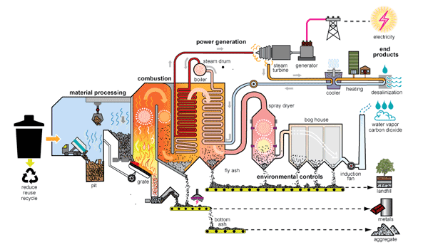
Once prepared, the biomass is conveyed into the energy conversion unit, which may employ direct combustion, gasification, pyrolysis, or anaerobic digestion technologies depending on the plant design and desired energy output. In direct combustion systems, biomass is burned in a boiler or furnace to generate steam, which then drives a turbine connected to a generator for electricity production. Gasification systems, on the other hand, convert biomass into a combustible gas mixture, known as syngas, through partial oxidation at high temperatures, which can then fuel internal combustion engines, gas turbines, or combined cycle systems. Pyrolysis processes thermally decompose biomass in the absence of oxygen to produce bio-oil, syngas, and char, offering flexibility for downstream energy utilization. Anaerobic digestion relies on microbial decomposition of wet biomass under controlled conditions to generate biogas, primarily composed of methane, which can be used in boilers, engines, or upgraded to biomethane for grid injection.
Critical to the plant’s operation is the management of heat and energy efficiency. Modern biomass plants often integrate combined heat and power (CHP) systems to maximize energy utilization, capturing both electricity and thermal energy for district heating or industrial processes. Flue gas cleaning and emission control systems are also essential, as combustion or gasification of biomass can release particulate matter, nitrogen oxides, and other pollutants. Technologies such as electrostatic precipitators, fabric filters, scrubbers, and selective catalytic reduction systems ensure compliance with stringent environmental regulations. Continuous monitoring and control systems optimize feedstock flow, combustion conditions, boiler pressure, temperature, and emissions, maintaining both efficiency and safety.
The plant also includes ash handling and residue management systems to deal with by-products such as bottom ash, fly ash, and digestate. Bottom ash is typically collected from the furnace and can be further processed for use in construction materials, while fly ash captured from flue gas cleaning is handled with care due to potential heavy metal content. In the case of anaerobic digestion, digestate is separated into solid and liquid fractions, with solids often used as soil conditioners and liquids recycled or treated for nutrient recovery. Storage and logistics infrastructure support the steady supply of biomass, including silos, hoppers, conveyor systems, and trucks, while robust safety measures address fire risks, dust explosions, and gas leaks.
Advanced biomass waste-to-energy plants increasingly employ digital monitoring, predictive maintenance, and energy management systems to optimize operations, reduce downtime, and enhance sustainability. Integration with renewable energy grids, flexible operation modes, and combined heat and power applications further increase the plant’s value proposition. Overall, such plants contribute significantly to circular economy objectives, reducing landfill dependency, mitigating greenhouse gas emissions, and providing renewable energy, all while managing a wide range of biomass feedstocks efficiently and safely.
Biomass Waste-to-Energy Plant

A biomass waste-to-energy plant operates as a complex, highly integrated system designed to extract energy from organic waste materials while minimizing environmental impact. The process begins with the careful reception and handling of biomass feedstock, which can include agricultural residues such as straw, husks, and stalks, forestry by-products like wood chips, sawdust, and bark, as well as green municipal waste, industrial organic residues, and certain forms of energy crops. Consistency in feedstock quality is vital, as variations in moisture content, particle size, and composition directly affect combustion efficiency, gasification quality, and the performance of downstream energy conversion systems. To achieve this, preprocessing facilities are employed to reduce particle size, remove contaminants, and, where necessary, dry the biomass to an optimal moisture level. Shredders, grinders, trommels, and dryers work together to produce a uniform, manageable material that can be fed continuously into the energy conversion units without interruptions or performance fluctuations, ensuring the plant maintains steady thermal output and efficiency.
Once processed, the biomass enters the energy conversion stage, which may employ direct combustion, advanced gasification, pyrolysis, or anaerobic digestion technologies, depending on the plant’s design and energy output requirements. In direct combustion systems, carefully controlled burning of biomass in high-efficiency boilers generates superheated steam that drives turbines connected to electrical generators, often integrated with combined heat and power applications to utilize both electricity and thermal energy for industrial processes or district heating. Gasification plants transform solid biomass into syngas through partial oxidation at high temperatures, producing a versatile fuel that can be combusted in internal combustion engines, gas turbines, or converted into chemicals and liquid biofuels. Pyrolysis, by contrast, decomposes biomass in the absence of oxygen to produce bio-oil, syngas, and char, providing flexible downstream options for energy or material use. Anaerobic digestion takes a different approach, using microbial processes in sealed, controlled digesters to break down wet biomass and organic residues, producing methane-rich biogas suitable for combustion in engines or boilers, or for purification and injection into natural gas grids, while the resulting digestate serves as a nutrient-rich soil amendment.
The efficiency and sustainability of a biomass waste-to-energy plant depend heavily on its thermal management, emissions control, and process optimization. Advanced plants integrate combined heat and power systems to maximize energy recovery, ensuring that heat generated during combustion or gasification is captured and reused for process heating, drying operations, or local heating networks. Emissions control systems are critical to compliance with environmental regulations and to protect air quality; they include electrostatic precipitators, fabric filters, cyclones, scrubbers, and selective catalytic reduction units that remove particulate matter, nitrogen oxides, sulfur compounds, and other pollutants from flue gases. Continuous monitoring and automation allow operators to adjust feed rates, combustion temperatures, oxygen levels, and pressure conditions in real time, maintaining optimal efficiency while minimizing harmful emissions. Sensors, programmable logic controllers, and energy management software work together to ensure that the plant operates within strict safety and environmental parameters, reducing the risk of operational disruptions or accidents associated with dust, flammable gases, or high-temperature equipment.
Residue handling and material recovery are equally important to the plant’s sustainability and economic viability. Bottom ash collected from combustion processes can be repurposed as aggregate material in construction, while fly ash captured through filtration systems must be carefully managed due to potential heavy metal content. In anaerobic digestion, the digestate is separated into solid and liquid fractions, with solids used as fertilizer or soil conditioner and liquids either treated for nutrient recovery or recycled into the process to maintain moisture balance. Logistics and storage infrastructure support consistent feedstock supply and residue handling, including silos, hoppers, conveyors, trucks, and automated material handling systems, which ensure smooth operations while minimizing labor and exposure risks.
Modern biomass waste-to-energy plants increasingly employ digital monitoring, predictive maintenance, and real-time energy optimization strategies to enhance operational efficiency, reduce downtime, and extend equipment life. Integration with renewable energy grids, flexible operation modes, and advanced control strategies allow plants to adapt to variations in feedstock supply, energy demand, and market conditions, making them highly resilient components of sustainable energy systems. By efficiently converting a wide range of biomass feedstocks into electricity, heat, and biogas, these plants contribute to reducing landfill dependency, lowering greenhouse gas emissions, and supporting circular economy objectives, all while providing reliable, renewable energy solutions. The combination of robust preprocessing, efficient energy conversion, stringent emissions control, sophisticated monitoring, and careful residue management makes a biomass waste-to-energy plant a highly effective and sustainable technology for addressing the dual challenges of waste management and renewable energy generation.
A biomass waste-to-energy plant represents a sophisticated integration of technologies aimed at converting organic waste streams into valuable energy while maintaining environmental compliance and operational efficiency. At its core, the plant begins with the reception and storage of a diverse range of biomass feedstocks, which can include agricultural residues such as straw, corn stover, and husks, forestry by-products including wood chips, sawdust, and bark, municipal green waste, organic fractions of industrial waste, and specially cultivated energy crops. Proper handling and preprocessing of these materials are crucial, as variations in moisture content, particle size, and chemical composition directly influence combustion characteristics, gasification performance, and the overall efficiency of energy conversion. Shredding, grinding, screening, and drying processes are employed to produce uniform biomass that can be reliably fed into energy conversion units without causing blockages or performance fluctuations. Conveyor systems, hoppers, and automated feed mechanisms ensure that the flow of biomass remains continuous, allowing for steady energy production and operational stability.
Once the feedstock is prepared, it enters the energy conversion phase, which may utilize direct combustion, gasification, pyrolysis, or anaerobic digestion depending on plant design and desired outputs. In direct combustion facilities, biomass is burned in highly controlled furnaces or boilers to generate superheated steam, which drives turbines connected to generators, producing electricity. Many modern plants combine this with heat recovery systems, enabling the simultaneous production of heat for district heating networks or industrial processes, effectively implementing combined heat and power (CHP) strategies that maximize overall energy efficiency. Gasification systems convert biomass into syngas, a mixture of carbon monoxide, hydrogen, and other combustible gases, through partial oxidation at high temperatures. This syngas can be combusted in internal combustion engines, gas turbines, or even processed into biofuels, providing flexibility in energy output. Pyrolysis thermally decomposes biomass in an oxygen-free environment, generating bio-oil, syngas, and char, each with multiple energy or material applications. Anaerobic digestion utilizes microbial activity under controlled conditions to produce biogas from wet organic waste streams, with methane-rich gas captured for use in engines, boilers, or purification for grid injection, while digestate is managed as a nutrient-rich soil amendment.
Thermal management, emissions control, and operational optimization are critical to the success of a biomass plant. Advanced plants integrate sophisticated heat recovery systems to utilize exhaust heat for drying feedstock, preheating boiler water, or supplying district heating, enhancing efficiency and reducing energy losses. Flue gas cleaning systems are essential for minimizing environmental impact, employing electrostatic precipitators, fabric filters, scrubbers, and catalytic reduction units to remove particulates, nitrogen oxides, sulfur compounds, and other potential pollutants. Automation and control systems continuously monitor combustion parameters, boiler pressure, temperature, feedstock flow rates, and emissions, allowing for real-time adjustments that maintain optimal efficiency and ensure compliance with environmental regulations. Safety systems are implemented to manage the risks associated with dust explosions, fire hazards, high-pressure steam, and flammable gases, while predictive maintenance strategies minimize downtime and prolong equipment life.
Residue and by-product management form an integral part of plant operations. Combustion generates bottom ash and fly ash, which require proper handling: bottom ash can be repurposed as construction material, while fly ash must be carefully contained due to potential heavy metal content. In anaerobic digestion systems, digestate is separated into solids and liquids; solids can serve as fertilizer or soil conditioners, and liquids may be treated for nutrient recovery or recycled into the process to maintain moisture balance. Storage and logistics systems, including silos, conveyors, and automated handling equipment, are essential to maintaining a consistent feedstock supply and ensuring safe, efficient residue management.
Modern biomass waste-to-energy plants increasingly incorporate digital monitoring, predictive analytics, and advanced energy management systems to enhance performance, reduce operational risks, and increase sustainability. Flexibility in operations allows plants to adapt to fluctuations in feedstock availability, energy demand, and grid requirements, ensuring continuous and efficient energy production. By efficiently converting biomass feedstocks into electricity, heat, and biogas, these plants not only provide renewable energy solutions but also contribute to reducing landfill dependency, lowering greenhouse gas emissions, and supporting circular economy objectives. The combination of feedstock preprocessing, efficient energy conversion, rigorous emissions control, real-time monitoring, and residue management positions biomass waste-to-energy technology as a vital solution for modern sustainable energy systems, addressing both waste management challenges and the growing need for renewable energy resources.
When discussing biomass waste-to-energy plants, the main types of technologies for converting biomass into energy can be grouped based on the method of energy conversion, and each type has its own operational characteristics, advantages, and applications. These types are generally described without breaking into sections but as a continuous explanation:
Biomass combustion or direct firing is the most established and widely used method. In this type, solid biomass feedstocks such as wood chips, agricultural residues, or municipal green waste are burned in a furnace or boiler to produce heat. This heat is then used to generate steam, which drives a turbine connected to an electricity generator, often in combination with heat recovery for district heating or industrial use, forming a combined heat and power (CHP) system. Combustion systems can handle a wide variety of feedstocks but require careful control of moisture content and particle size to maintain stable operation and reduce emissions.
Gasification is another major type, where biomass is converted into a combustible gas mixture known as syngas through partial oxidation at high temperatures in a controlled oxygen environment. This syngas, primarily composed of carbon monoxide, hydrogen, and small amounts of methane, can then be used to fuel gas engines, turbines, or further processed into liquid biofuels or chemicals. Gasification offers higher efficiency than simple combustion and enables more flexible energy use, though it requires more sophisticated control systems and feedstock preparation.
Pyrolysis is a thermochemical process that decomposes biomass in the absence of oxygen, producing bio-oil, syngas, and char. Bio-oil can be used as a renewable liquid fuel for boilers or engines, syngas can be burned for electricity, and char can serve as a soil amendment or solid fuel. Pyrolysis is particularly useful for managing high-moisture or heterogeneous biomass streams and allows for diversified energy and material outputs.
Anaerobic digestion represents a biological conversion type, in which wet biomass such as food waste, agricultural slurry, or sewage sludge is decomposed by microorganisms in sealed, oxygen-free digesters. This process produces methane-rich biogas, which can be used for electricity generation, heating, or injection into natural gas grids after purification. The residual digestate is a nutrient-rich material suitable for fertilizer use. Anaerobic digestion is highly suitable for wet organic waste and contributes to both renewable energy generation and nutrient recycling.
Advanced combined or hybrid systems integrate these technologies to optimize energy recovery from biomass. For instance, gasification or pyrolysis can be paired with combustion of the residual char to maximize energy efficiency, while anaerobic digestion can be combined with CHP systems to utilize biogas for electricity and heat. These hybrid approaches increase flexibility, efficiency, and the ability to handle diverse biomass streams while supporting environmental and sustainability goals.
Overall, the main types of biomass waste-to-energy plants—direct combustion, gasification, pyrolysis, anaerobic digestion, and hybrid systems—offer a spectrum of technical solutions for converting organic waste into electricity, heat, and biogas. The choice of type depends on feedstock characteristics, desired energy outputs, environmental requirements, and economic considerations, allowing biomass energy technology to be adapted to different industrial, municipal, or agricultural applications.
Biomass Energy Recovery Plant
A biomass energy recovery plant is a highly specialized facility designed to convert organic waste materials, including agricultural residues, forestry by-products, municipal green waste, food processing residues, and certain industrial organic wastes, into usable forms of energy such as electricity, heat, or biogas, while minimizing environmental impact and supporting sustainable resource management. The process begins with feedstock reception, where raw biomass is collected, sorted, and temporarily stored to ensure a continuous and uniform supply. Preprocessing is a critical step, as variations in moisture content, particle size, and material composition can significantly affect the efficiency of energy conversion processes. Preprocessing equipment such as shredders, grinders, trommels, and dryers is used to produce biomass of a consistent size and dryness, which facilitates smooth feeding into energy conversion systems and prevents operational disruptions or inefficiencies. Advanced plants often incorporate automated feeding systems, hoppers, and conveyor mechanisms to maintain continuous and controlled material flow.
Once prepared, the biomass enters the energy conversion phase, which may involve direct combustion, gasification, pyrolysis, or anaerobic digestion depending on the plant design and desired energy outputs. In direct combustion systems, biomass is burned in high-efficiency boilers to generate superheated steam, which drives turbines connected to generators for electricity production. Many modern facilities integrate combined heat and power (CHP) systems to utilize the thermal energy produced during combustion for district heating, industrial processes, or other thermal applications, thereby maximizing energy recovery. Gasification technology converts biomass into a combustible syngas composed mainly of carbon monoxide, hydrogen, and methane through partial oxidation at high temperatures. This syngas can fuel internal combustion engines, gas turbines, or be further processed into liquid biofuels and chemicals, providing a versatile and efficient energy conversion route. Pyrolysis thermally decomposes biomass in an oxygen-free environment to generate bio-oil, syngas, and char, which can all be used for energy or material applications. Anaerobic digestion employs microbial processes to decompose wet organic waste under oxygen-free conditions, producing methane-rich biogas suitable for electricity generation, heating, or upgrading to biomethane for grid injection, with the resulting digestate serving as a nutrient-rich soil conditioner.
Efficient thermal management, emissions control, and operational optimization are key to the successful operation of a biomass energy recovery plant. Modern plants employ heat recovery systems that capture waste heat from combustion or gasification for use in preheating biomass, drying feedstock, or supplying local heating networks, increasing overall energy efficiency. Advanced flue gas cleaning systems, including electrostatic precipitators, fabric filters, scrubbers, and selective catalytic reduction units, remove particulates, nitrogen oxides, sulfur compounds, and other pollutants, ensuring compliance with environmental regulations. Continuous monitoring and automation of feed rates, combustion temperature, oxygen concentration, and boiler pressure allow real-time optimization of energy conversion and emissions, while safety systems mitigate risks associated with dust explosions, flammable gases, and high-pressure steam. Predictive maintenance programs, digital monitoring, and remote diagnostics further enhance operational reliability and reduce unplanned downtime.
Residue management is an integral component of biomass energy recovery plants. Combustion produces bottom ash and fly ash, which must be handled carefully: bottom ash can be repurposed as construction material, while fly ash is treated to minimize environmental risks. In anaerobic digestion, the digestate is separated into solid and liquid fractions, with solids often used as fertilizer or soil conditioner and liquids treated for nutrient recovery or recycled within the process. Storage and logistics systems, including silos, hoppers, conveyor systems, and trucks, support consistent feedstock supply and efficient residue handling, reducing labor requirements and operational bottlenecks.
Modern biomass energy recovery plants increasingly incorporate digital energy management systems, predictive analytics, and advanced process control to enhance efficiency, reduce operational risks, and extend equipment life. Hybrid configurations combining combustion, gasification, pyrolysis, or anaerobic digestion are also becoming more common, maximizing energy output and providing flexibility in handling diverse biomass streams. By converting waste biomass into electricity, heat, and biogas, these plants contribute to circular economy objectives, reduce landfill dependence, mitigate greenhouse gas emissions, and provide renewable energy solutions for industrial, municipal, and agricultural applications. The integration of preprocessing, efficient energy conversion, emissions control, digital monitoring, and residue management ensures that biomass energy recovery plants operate sustainably, safely, and efficiently, making them a critical technology for modern renewable energy and waste management strategies.
A biomass energy recovery plant functions as an integrated system designed to transform organic waste materials into usable energy in the form of electricity, heat, or biogas while ensuring environmental compliance and operational efficiency. The plant begins with the reception and handling of biomass feedstock, which can encompass agricultural residues such as straw, husks, and stalks, forestry by-products including wood chips, sawdust, and bark, municipal green waste, food processing residues, and select industrial organic waste streams. Proper feedstock management is critical because variations in moisture content, particle size, and chemical composition can significantly impact combustion efficiency, gasification quality, or digestion performance. Preprocessing facilities such as shredders, grinders, trommels, and dryers ensure that biomass is uniform, manageable, and suitable for continuous feeding into the conversion units. Advanced conveyor systems, automated hoppers, and metered feeding mechanisms maintain a steady flow of material, preventing blockages or interruptions that could compromise energy output or damage equipment.
Once the biomass is prepared, it enters the energy conversion phase, which may involve direct combustion, gasification, pyrolysis, anaerobic digestion, or hybrid approaches depending on the plant design and energy requirements. In direct combustion systems, biomass is burned in high-efficiency furnaces or boilers to generate superheated steam, which powers turbines connected to generators for electricity production. Many modern facilities utilize combined heat and power (CHP) systems, allowing the simultaneous capture and use of thermal energy for district heating or industrial applications, enhancing overall energy efficiency. Gasification technology converts solid biomass into a combustible syngas through partial oxidation at high temperatures; this syngas can then be combusted in engines or turbines, or processed into liquid biofuels or chemical intermediates, providing versatile and efficient energy utilization. Pyrolysis thermochemically decomposes biomass in an oxygen-free environment, producing bio-oil, syngas, and char, each of which can serve energy or material applications, offering flexibility for waste streams with high moisture or mixed compositions. Anaerobic digestion leverages microbial processes to break down wet organic biomass in oxygen-free digesters, producing methane-rich biogas suitable for electricity generation, heating, or purification for grid injection, with digestate acting as a nutrient-rich soil conditioner.
Thermal management and emissions control are central to the plant’s sustainable operation. Heat recovery systems capture waste heat from combustion or gasification processes for preheating biomass, drying feedstock, or supplying district heating networks, increasing overall energy efficiency and reducing losses. Advanced flue gas cleaning systems, including electrostatic precipitators, fabric filters, cyclones, scrubbers, and selective catalytic reduction units, remove particulate matter, nitrogen oxides, sulfur compounds, and other pollutants, ensuring compliance with strict environmental regulations. Automation and monitoring systems continuously track combustion parameters, boiler pressure, temperature, oxygen levels, and feedstock flow rates, allowing real-time adjustments to optimize energy output and emissions. Safety systems are implemented to mitigate risks associated with high-pressure steam, flammable gases, and combustible dust, while predictive maintenance programs and remote diagnostics enhance operational reliability and minimize downtime.
Residue management is another crucial component of biomass energy recovery plants. Combustion produces bottom ash and fly ash, which are handled and processed to reduce environmental risks: bottom ash can be reused in construction materials, while fly ash is carefully treated to mitigate potential heavy metal content. In anaerobic digestion, digestate is separated into solid and liquid fractions, with solids often used as fertilizer or soil amendments and liquids treated for nutrient recovery or recycled to maintain process moisture balance. Storage and logistics systems, including silos, hoppers, conveyors, and trucks, facilitate continuous feedstock supply and efficient handling of by-products, reducing labor requirements and operational bottlenecks.
Modern biomass energy recovery plants increasingly integrate digital monitoring, predictive analytics, and energy management systems to optimize efficiency, reduce operational risks, and extend equipment life. Hybrid configurations, which combine combustion, gasification, pyrolysis, or anaerobic digestion, are increasingly used to maximize energy recovery and handle diverse biomass streams with varying moisture, composition, and particle size. By converting biomass into electricity, heat, and biogas, these plants contribute to circular economy objectives, reduce landfill dependency, mitigate greenhouse gas emissions, and provide renewable energy solutions across industrial, municipal, and agricultural sectors. The integration of preprocessing, efficient energy conversion, emissions control, digital monitoring, and residue management ensures that biomass energy recovery plants operate sustainably, safely, and efficiently, establishing them as a vital technology in modern renewable energy and waste management strategies.
A biomass energy recovery plant is a complex and highly integrated facility designed to efficiently convert a wide range of organic waste materials into useful forms of energy, including electricity, heat, and biogas, while adhering to strict environmental and safety standards. The process begins with the reception and handling of biomass feedstocks, which may include agricultural residues such as straw, corn stalks, husks, and cobs, forestry by-products including wood chips, sawdust, and bark, municipal green waste, food processing residues, and certain industrial organic wastes. The quality, moisture content, particle size, and composition of these feedstocks are critical factors affecting the efficiency of energy conversion processes. Preprocessing equipment such as shredders, grinders, trommels, and dryers is employed to create a uniform material suitable for continuous feeding into combustion, gasification, pyrolysis, or anaerobic digestion systems. Automated conveyors, hoppers, and feeding mechanisms ensure a steady flow of biomass, preventing blockages, interruptions, or fluctuations in energy output that could compromise the stability of the plant.
The core of a biomass energy recovery plant lies in its energy conversion units, which may operate on one or multiple principles depending on the plant design. In direct combustion systems, biomass is burned in high-efficiency furnaces or boilers to generate superheated steam, which drives turbines connected to electricity generators. Many modern facilities incorporate combined heat and power (CHP) systems, allowing thermal energy from combustion to be captured and used for district heating networks, industrial processes, or on-site energy needs, maximizing overall energy utilization. Gasification processes convert solid biomass into a combustible gas mixture, known as syngas, through partial oxidation at high temperatures. This syngas can be used in internal combustion engines, gas turbines, or further processed into liquid biofuels or chemicals, offering high efficiency and flexibility. Pyrolysis thermochemically decomposes biomass in the absence of oxygen to produce bio-oil, syngas, and char, each with multiple energy or material applications. Anaerobic digestion uses microbial processes to decompose wet organic biomass in oxygen-free digesters, generating methane-rich biogas for electricity, heat, or purification for grid injection, while the digestate is recovered as a nutrient-rich soil amendment.
Efficient thermal management and emissions control are fundamental to the sustainable operation of biomass energy recovery plants. Advanced heat recovery systems capture waste heat from combustion or gasification processes for preheating biomass, drying feedstock, or supplying district heating networks, significantly improving overall efficiency. Flue gas cleaning systems, including electrostatic precipitators, fabric filters, scrubbers, and selective catalytic reduction units, remove particulates, nitrogen oxides, sulfur compounds, and other pollutants, ensuring compliance with environmental regulations and minimizing impact on air quality. Automation, monitoring, and control systems track combustion parameters, feedstock flow rates, oxygen levels, boiler pressure, and temperatures in real time, allowing operators to optimize performance, maintain stable operations, and minimize emissions. Safety systems address the risks associated with high-pressure steam, flammable gases, combustible dust, and mechanical failures, while predictive maintenance and digital monitoring reduce downtime and prolong equipment life.
Residue and by-product management is a crucial aspect of biomass energy recovery plants. Combustion generates bottom ash and fly ash, which must be collected, treated, and either safely disposed of or repurposed. Bottom ash can often be used in construction materials, while fly ash is treated to minimize environmental risks due to potential heavy metal content. Anaerobic digestion produces digestate, which is separated into solid and liquid fractions. Solid digestate can be used as fertilizer or soil conditioner, while liquid fractions are often treated for nutrient recovery or recycled to maintain moisture balance within the digester. Storage, logistics, and material handling systems, including silos, hoppers, conveyors, and trucks, are critical for maintaining a consistent feedstock supply and efficient residue handling, reducing labor requirements and operational bottlenecks.
Modern biomass energy recovery plants increasingly rely on digital monitoring, predictive analytics, and advanced energy management systems to optimize performance, improve energy recovery, and enhance operational safety. Hybrid configurations that integrate combustion, gasification, pyrolysis, or anaerobic digestion allow plants to handle a wide range of biomass feedstocks with varying moisture content, composition, and particle size, maximizing flexibility and efficiency. These plants contribute significantly to circular economy objectives by reducing landfill dependency, lowering greenhouse gas emissions, and producing renewable energy that can be used locally or fed into national grids. The combination of preprocessing, efficient energy conversion, emissions control, real-time monitoring, safety systems, and residue management ensures that biomass energy recovery plants operate sustainably, reliably, and efficiently, establishing them as a key technology for modern waste management and renewable energy generation strategies.
By carefully coordinating feedstock handling, energy conversion processes, heat recovery, emission controls, and by-product management, biomass energy recovery plants transform organic waste streams into valuable energy while supporting environmental sustainability, resource efficiency, and energy security. These plants provide an essential bridge between waste management and renewable energy generation, converting what would otherwise be discarded as low-value biomass into high-value electricity, heat, and biogas. Their adaptability to different types of biomass and integration with industrial, municipal, or agricultural energy systems make them highly versatile solutions in the global transition toward clean energy. With ongoing advancements in process automation, hybrid conversion technologies, and emission mitigation, biomass energy recovery plants continue to increase in efficiency, environmental performance, and economic viability, reinforcing their role as a cornerstone of sustainable energy infrastructure.
Biomass CHP System
A biomass combined heat and power (CHP) system is an advanced technology designed to simultaneously generate electricity and useful heat from organic biomass materials, providing highly efficient energy utilization while supporting sustainable waste management and renewable energy goals. In a biomass CHP system, organic waste streams such as agricultural residues, forestry by-products, wood chips, sawdust, municipal green waste, food processing residues, and certain industrial organic wastes are collected, sorted, and prepared for energy conversion. Proper preprocessing of biomass is essential to ensure uniformity in moisture content, particle size, and composition, which directly impacts system efficiency and operational stability. Shredders, grinders, trommels, and dryers are used to process biomass into a consistent feedstock, while automated conveyors, hoppers, and feeding mechanisms maintain continuous and controlled material flow to the energy conversion unit. This consistent feedstock supply is crucial for preventing blockages, maintaining steady steam production, and ensuring reliable operation of turbines and engines.
The core of a biomass CHP system is its energy conversion process, which may utilize direct combustion, gasification, or anaerobic digestion technologies. In combustion-based systems, biomass is burned in high-efficiency boilers to generate superheated steam, which drives a steam turbine or reciprocating engine connected to an electrical generator. The waste heat from this process is captured in heat exchangers and distributed as thermal energy for district heating networks, industrial processes, or on-site heating, enabling combined heat and power generation and significantly improving overall energy efficiency compared to electricity-only generation. Gasification-based CHP systems convert biomass into syngas through partial oxidation at high temperatures, producing a clean and versatile fuel that can be used in gas engines, gas turbines, or further processed into biofuels and chemicals. The heat generated in these systems can also be recovered for heating applications, further enhancing the energy yield of the biomass feedstock. Anaerobic digestion-based CHP systems process wet biomass and organic residues in oxygen-free digesters, generating methane-rich biogas that can be combusted in engines or boilers to simultaneously produce electricity and heat, while the remaining digestate serves as a nutrient-rich soil amendment.
Efficient operation of a biomass CHP system depends heavily on thermal management, emissions control, and automated process optimization. Heat recovery systems capture exhaust heat from turbines, engines, and flue gases to maximize energy utilization, preheat biomass, or supply thermal networks, reducing overall fuel consumption and increasing plant efficiency. Flue gas cleaning and emissions control systems, such as electrostatic precipitators, fabric filters, scrubbers, and selective catalytic reduction units, remove particulates, nitrogen oxides, sulfur compounds, and other pollutants, ensuring compliance with environmental standards. Advanced monitoring and automation technologies continuously track parameters such as feedstock flow, combustion temperature, oxygen concentration, boiler pressure, and turbine speed, allowing real-time optimization of energy production and emission reduction. Safety systems manage the risks associated with high-pressure steam, flammable gases, combustible dust, and other hazards, while predictive maintenance programs, digital diagnostics, and remote monitoring reduce unplanned downtime and enhance operational reliability.
Residue and by-product management is an integral component of biomass CHP systems. Combustion generates bottom ash and fly ash, which are collected, treated, and either safely disposed of or repurposed, for example as construction material, while fly ash is carefully managed to mitigate environmental risks. Anaerobic digestion produces digestate, which is separated into solid and liquid fractions; solids can be used as fertilizer or soil conditioner, and liquids can be treated for nutrient recovery or recycled within the digester to maintain moisture balance. Storage, handling, and logistics systems, including silos, conveyors, hoppers, and trucks, ensure a consistent supply of feedstock and facilitate efficient handling of residues, reducing labor requirements and operational bottlenecks.
Modern biomass CHP systems increasingly integrate digital energy management, predictive analytics, and hybrid configurations to optimize efficiency, adapt to varying feedstock characteristics, and maximize energy recovery. Hybrid systems may combine combustion, gasification, or anaerobic digestion processes to handle different types of biomass and improve overall plant flexibility. These systems contribute to circular economy objectives by reducing waste sent to landfills, lowering greenhouse gas emissions, and generating renewable energy for industrial, municipal, and agricultural applications. The integration of feedstock preprocessing, efficient energy conversion, heat recovery, emissions control, automated monitoring, and residue management ensures that biomass CHP plants operate sustainably, safely, and reliably, establishing them as a cornerstone of modern renewable energy infrastructure and waste-to-energy solutions.
By converting organic waste into both electricity and thermal energy, biomass CHP systems maximize the energy potential of biomass feedstocks and provide a versatile, environmentally responsible solution to the dual challenges of renewable energy generation and organic waste management. Their adaptability to different feedstock types, advanced process control, and integration with district heating, industrial applications, or local energy networks make biomass CHP plants a highly efficient, sustainable, and economically viable technology for modern energy systems. These plants exemplify the synergy between waste management and renewable energy production, turning biomass into a continuous, reliable source of combined heat and power while supporting broader environmental and energy sustainability goals.
A biomass CHP system is a highly integrated energy solution designed to extract maximum value from organic waste streams by simultaneously producing electricity and useful heat, creating a highly efficient and sustainable energy cycle. The process begins with the careful reception, sorting, and storage of biomass feedstocks, which can include agricultural residues such as straw, husks, stalks, and corn cobs, forestry by-products like wood chips, sawdust, and bark, municipal green waste, food processing residues, and selected industrial organic wastes. The quality, moisture content, particle size, and consistency of these feedstocks are crucial, as variations directly influence the performance and efficiency of the energy conversion process. Preprocessing equipment such as shredders, grinders, trommels, and dryers is used to create a uniform biomass material suitable for continuous feeding into combustion, gasification, or anaerobic digestion units. Automated conveyors, hoppers, and metered feeding systems maintain a controlled and uninterrupted supply of biomass, preventing blockages, maintaining stable steam or gas production, and ensuring reliable electricity generation and thermal output.
The core energy conversion of a biomass CHP system can utilize a variety of technologies depending on the plant design, feedstock type, and energy output requirements. Combustion-based systems burn biomass in high-efficiency boilers to produce superheated steam that drives turbines connected to generators, simultaneously generating electricity and heat. Heat recovery systems capture thermal energy from flue gases, turbines, and exhaust streams for use in district heating networks, industrial processes, or on-site heating applications, significantly enhancing the overall energy efficiency of the system. Gasification-based CHP plants convert biomass into syngas through partial oxidation at high temperatures. This syngas can then be combusted in internal combustion engines, gas turbines, or further processed into biofuels or chemicals. The heat generated during this process is recovered through heat exchangers and utilized for thermal energy applications, providing a dual energy output. Anaerobic digestion-based CHP systems process wet organic waste in oxygen-free digesters, generating methane-rich biogas that fuels engines or boilers to produce both electricity and heat, while the remaining digestate can be used as a nutrient-rich soil conditioner or fertilizer, closing the nutrient cycle and contributing to sustainable agricultural practices.
The efficiency and sustainability of a biomass CHP system rely heavily on advanced thermal management, emissions control, and automated process optimization. Heat recovery from exhaust gases, turbines, and engine cooling systems is used to preheat incoming biomass, supply district heating, or provide industrial process heat, minimizing energy losses and maximizing the usable energy extracted from the feedstock. Flue gas cleaning and emissions control systems, including fabric filters, electrostatic precipitators, cyclones, scrubbers, and selective catalytic reduction units, are essential for removing particulate matter, nitrogen oxides, sulfur compounds, and other pollutants, ensuring the plant operates within strict environmental regulations. Modern CHP systems employ sophisticated digital monitoring and control systems that continuously track feedstock flow, combustion temperature, boiler or engine pressure, oxygen levels, and turbine or engine performance, allowing real-time adjustments to optimize energy output and minimize emissions. Safety systems manage risks associated with high-pressure steam, combustible dust, flammable gases, and mechanical failures, while predictive maintenance, remote diagnostics, and automated fault detection enhance reliability and reduce unplanned downtime.
Residue and by-product management is a crucial aspect of biomass CHP plant operation. Combustion produces bottom ash and fly ash, which must be collected, treated, and either safely disposed of or repurposed in applications such as construction materials. Fly ash is handled carefully to mitigate potential environmental impacts due to heavy metal content. In anaerobic digestion systems, digestate is separated into solid and liquid fractions; solids are often used as fertilizer or soil conditioner, while liquid fractions are treated for nutrient recovery or recycled to maintain digester moisture levels. Storage, handling, and logistics systems, including silos, hoppers, conveyors, and trucks, ensure a steady feedstock supply and efficient handling of by-products, reducing labor requirements and operational bottlenecks.
Modern biomass CHP systems increasingly adopt hybrid configurations that combine combustion, gasification, and anaerobic digestion processes to improve feedstock flexibility, maximize energy recovery, and handle a wide range of biomass characteristics. These hybrid systems allow plants to efficiently manage variations in moisture content, particle size, and chemical composition of feedstocks while providing both electricity and heat to industrial, municipal, or agricultural applications. Digital energy management systems, predictive analytics, and automated controls optimize performance, enhance fuel efficiency, and extend equipment life, ensuring that the plant operates reliably, safely, and sustainably. By converting diverse organic waste streams into electricity, thermal energy, and biogas, biomass CHP systems contribute to circular economy objectives, reduce reliance on landfills, lower greenhouse gas emissions, and provide renewable energy solutions that are both economically and environmentally viable.
Through careful integration of feedstock handling, preprocessing, energy conversion, heat recovery, emissions control, automated monitoring, and residue management, biomass CHP systems transform biomass into a reliable and efficient source of combined heat and power. These systems demonstrate the synergy between sustainable waste management and renewable energy generation, turning materials that would otherwise be discarded into high-value energy while supporting environmental protection, resource efficiency, and energy security. With continued advances in hybrid technology, digital monitoring, process optimization, and emission reduction, biomass CHP systems represent a cornerstone of modern sustainable energy infrastructure, capable of delivering continuous, reliable, and efficient energy while promoting a circular and low-carbon economy.
A biomass CHP system is an advanced and highly integrated energy solution that captures the full potential of organic waste streams by simultaneously generating electricity and useful heat, making it one of the most efficient methods of converting biomass into energy. The process starts with the collection, sorting, and storage of a wide variety of biomass feedstocks, including agricultural residues such as straw, husks, corn stalks, and cobs, forestry by-products like wood chips, sawdust, and bark, municipal green waste, food processing residues, and select industrial organic wastes. Proper feedstock management is crucial to system efficiency, as variations in moisture content, particle size, density, and chemical composition can significantly impact combustion, gasification, or digestion performance. Preprocessing equipment such as shredders, grinders, trommels, and dryers ensures that the biomass is uniform and suitable for continuous feeding, while automated hoppers, conveyors, and metered feeding systems maintain a steady and controlled supply to the energy conversion unit. This continuous flow of feedstock prevents operational interruptions, ensures stable steam or gas production, and maintains consistent electricity generation and heat output throughout the plant’s operation.
The energy conversion process in a biomass CHP system can involve combustion, gasification, or anaerobic digestion, depending on the specific design and the characteristics of the biomass feedstock. In combustion-based CHP systems, biomass is burned in high-efficiency boilers to produce superheated steam that drives turbines or reciprocating engines connected to electricity generators. The heat produced during combustion is captured through heat exchangers and used for district heating, industrial processes, or on-site thermal applications, dramatically improving the overall energy efficiency of the system. Gasification-based CHP plants convert solid biomass into syngas, a mixture of carbon monoxide, hydrogen, and methane, through partial oxidation at elevated temperatures. This syngas can then be combusted in internal combustion engines or gas turbines to generate electricity, while residual heat is recovered for thermal applications. Anaerobic digestion-based CHP systems process wet biomass and organic residues in sealed, oxygen-free digesters, producing methane-rich biogas that fuels engines or boilers to produce both electricity and heat, while the digestate serves as a nutrient-rich fertilizer or soil conditioner, closing the nutrient loop and supporting sustainable agriculture.
Efficiency and sustainability in biomass CHP systems rely heavily on advanced thermal management, emissions control, and process optimization. Heat recovery systems capture energy from flue gases, exhaust streams, turbines, and engine cooling circuits, using it to preheat incoming biomass, supply district heating, or provide thermal energy to industrial processes, reducing fuel consumption and maximizing the energy extracted from the biomass. Flue gas cleaning technologies, including fabric filters, electrostatic precipitators, cyclones, scrubbers, and selective catalytic reduction units, remove particulates, nitrogen oxides, sulfur compounds, and other pollutants to ensure compliance with stringent environmental regulations and to minimize impact on air quality. Sophisticated monitoring and automation systems continuously track critical parameters such as feedstock flow, combustion temperature, boiler or engine pressure, oxygen levels, and turbine or engine performance, enabling real-time adjustments that optimize energy output and minimize emissions. Safety systems address hazards associated with high-pressure steam, flammable gases, combustible dust, and mechanical equipment, while predictive maintenance, digital diagnostics, and automated fault detection enhance reliability and reduce unplanned downtime.
Residue and by-product management is a fundamental component of biomass CHP operation. Combustion produces bottom ash and fly ash, which are collected, treated, and either safely disposed of or repurposed; bottom ash can often be used as construction material, while fly ash is carefully managed to mitigate environmental risks from heavy metals or other contaminants. Anaerobic digestion produces digestate, which is separated into solid and liquid fractions. Solids can serve as fertilizer or soil conditioner, while liquid fractions are either treated for nutrient recovery or recycled to maintain moisture levels in the digester. Robust storage, handling, and logistics systems, including silos, hoppers, conveyors, and trucks, ensure a continuous feedstock supply and efficient management of residues, minimizing labor requirements and preventing operational bottlenecks.
Modern biomass CHP systems increasingly incorporate hybrid configurations that combine combustion, gasification, and anaerobic digestion to enhance feedstock flexibility, maximize energy recovery, and efficiently handle a wide range of biomass materials with varying moisture content, particle size, and chemical composition. These hybrid systems allow for highly adaptable energy production, supplying electricity and heat to industrial, municipal, and agricultural applications with high efficiency. Digital energy management, predictive analytics, and automated process controls are used to optimize performance, improve fuel utilization, extend equipment life, and enhance environmental performance. By converting diverse organic waste streams into electricity, thermal energy, and biogas, biomass CHP systems contribute to circular economy objectives, reduce landfill dependence, mitigate greenhouse gas emissions, and provide renewable energy solutions that are economically viable and environmentally sustainable.
Through the careful integration of feedstock handling, preprocessing, energy conversion, heat recovery, emissions control, digital monitoring, safety management, and residue handling, biomass CHP systems transform organic waste into reliable and efficient sources of combined heat and power. These plants exemplify the synergy between renewable energy generation and sustainable waste management, converting materials that would otherwise be discarded into continuous, high-value electricity and thermal energy. With ongoing advancements in hybrid conversion technologies, process optimization, digital monitoring, and emissions mitigation, biomass CHP systems continue to improve in efficiency, reliability, and sustainability, reinforcing their role as a cornerstone of modern renewable energy infrastructure and circular economy strategies. They provide flexible, resilient, and high-efficiency energy solutions while simultaneously addressing environmental and waste management challenges, making them a key technology for industrial, municipal, and agricultural energy applications around the world.
A biomass CHP system is a highly advanced, integrated facility designed to extract the maximum energy potential from organic waste streams by simultaneously generating electricity and useful heat, delivering exceptional efficiency compared to traditional single-output energy systems. The operation begins with the collection, reception, sorting, and storage of a wide variety of biomass feedstocks, which may include agricultural residues such as straw, corn stalks, husks, and cobs, forestry by-products like wood chips, sawdust, bark, and logging residues, municipal green waste, food processing residues, and selected industrial organic by-products. The quality, moisture content, particle size, and chemical composition of these feedstocks are critical parameters that directly influence combustion, gasification, or anaerobic digestion efficiency. To ensure operational stability and consistent energy output, preprocessing equipment such as shredders, grinders, trommels, and dryers is used to produce a uniform biomass feedstock. Automated hoppers, conveyors, and metered feeding mechanisms maintain a controlled, uninterrupted flow of material into the energy conversion units, preventing blockages, fluctuations, and inefficiencies that could compromise the generation of electricity and heat.
In a biomass CHP system, energy conversion can be achieved through multiple technologies depending on the plant design, feedstock characteristics, and desired energy outputs. Combustion-based systems burn biomass in high-efficiency boilers to generate superheated steam, which drives turbines or reciprocating engines coupled with electrical generators. The waste heat from these systems is captured via heat exchangers and distributed to district heating networks, industrial processes, or on-site thermal applications, significantly enhancing the overall energy utilization of the biomass feedstock. Gasification-based CHP systems convert biomass into syngas, a mixture of carbon monoxide, hydrogen, and methane, through partial oxidation at high temperatures. This syngas can then be combusted in internal combustion engines or gas turbines, producing electricity, while the thermal energy is recovered for heat applications. Anaerobic digestion-based CHP systems leverage microbial activity in oxygen-free digesters to process wet biomass, food waste, or slurry, generating methane-rich biogas that fuels engines or boilers for combined electricity and heat production, while the digestate serves as a nutrient-rich fertilizer or soil conditioner, closing the nutrient cycle and supporting sustainable agricultural practices.
The efficiency and sustainability of biomass CHP plants depend on advanced thermal management, emissions control, and automated process optimization. Heat recovery systems capture thermal energy from flue gases, turbines, engines, and cooling circuits, using it to preheat biomass, supply district heating, or provide process heat to industrial operations, minimizing energy losses and improving overall plant efficiency. Sophisticated flue gas cleaning technologies, including fabric filters, electrostatic precipitators, cyclones, scrubbers, and selective catalytic reduction units, remove particulate matter, nitrogen oxides, sulfur compounds, and other pollutants to ensure compliance with strict environmental regulations. Digital monitoring and automation systems continuously track key parameters such as feedstock flow, combustion temperature, boiler or engine pressure, oxygen levels, and turbine or engine performance, allowing real-time adjustments that optimize energy output, maintain system stability, and minimize emissions. Safety systems are implemented to mitigate risks associated with high-pressure steam, combustible dust, flammable gases, and mechanical failures, while predictive maintenance, remote diagnostics, and automated fault detection enhance plant reliability and minimize unplanned downtime.
Residue and by-product management is a critical aspect of biomass CHP operations. Combustion generates bottom ash and fly ash, which must be collected, treated, and either safely disposed of or repurposed; bottom ash can often be reused in construction applications, while fly ash is carefully managed to reduce potential environmental risks associated with heavy metals. Anaerobic digestion produces digestate, which is separated into solid and liquid fractions. Solid digestate can be applied as fertilizer or soil conditioner, while liquid fractions are treated for nutrient recovery or recycled to maintain digester moisture balance. Robust storage, handling, and logistics infrastructure, including silos, conveyors, hoppers, and trucks, ensures a steady and reliable feedstock supply, while facilitating efficient handling of residues and by-products, reducing labor requirements and operational bottlenecks.
Modern biomass CHP systems increasingly utilize hybrid configurations that combine combustion, gasification, and anaerobic digestion technologies to enhance operational flexibility, maximize energy recovery, and handle a diverse range of biomass feedstocks with varying moisture content, particle size, and chemical composition. These hybrid systems allow for high adaptability, enabling continuous and efficient production of both electricity and heat for industrial, municipal, or agricultural applications. Integration with digital energy management systems, predictive analytics, and automated controls optimizes performance, increases fuel utilization efficiency, extends equipment life, and improves environmental compliance. By converting diverse organic waste streams into electricity, thermal energy, and biogas, biomass CHP systems support circular economy principles, reduce landfill dependency, lower greenhouse gas emissions, and provide renewable energy solutions that are both economically and environmentally sustainable.
The successful operation of biomass CHP systems relies on careful coordination of feedstock handling, preprocessing, energy conversion, heat recovery, emissions control, residue management, and digital process monitoring. These systems transform organic waste into continuous, high-value energy while simultaneously addressing waste management challenges and promoting resource efficiency. The integration of hybrid technologies, real-time process control, and predictive maintenance ensures that the plant operates efficiently, safely, and sustainably under varying feedstock conditions and energy demands. By maximizing the energy potential of biomass feedstocks and providing reliable electricity and heat, biomass CHP plants play a vital role in renewable energy infrastructure, supporting industrial, municipal, and agricultural energy needs while contributing to environmental protection, sustainable resource management, and the advancement of a low-carbon circular economy.
Biomass Boiler System
A biomass boiler system is a critical component in renewable energy production, designed to convert organic biomass materials into thermal energy for heating, steam generation, or combined heat and power (CHP) applications, providing a highly efficient and environmentally sustainable solution for industrial, municipal, and agricultural energy needs. The operation of a biomass boiler system begins with the careful reception, sorting, and storage of a wide range of biomass feedstocks, including agricultural residues such as straw, husks, stalks, corn cobs, and other crop by-products, forestry residues like wood chips, sawdust, bark, and small branches, municipal green waste, food processing residues, and certain organic industrial by-products. The physical characteristics of the feedstock—moisture content, particle size, density, and chemical composition—are crucial factors that influence combustion efficiency, heat output, and emissions performance. Preprocessing equipment, such as shredders, grinders, trommels, and dryers, is employed to create a uniform and manageable biomass feed suitable for continuous feeding into the boiler. Automated hoppers, conveyors, and metered feeding systems ensure a consistent and controlled supply of fuel to the combustion chamber, preventing operational interruptions, improving thermal efficiency, and maintaining steady heat output.
In a biomass boiler system, the core energy conversion process relies on the controlled combustion of biomass to produce thermal energy, which is transferred to water or steam via heat exchangers. High-efficiency boilers are designed to optimize fuel combustion, minimize heat losses, and ensure stable steam or hot water production. Advanced systems may include moving grate, fluidized bed, or pulverized fuel designs, each capable of handling different types of biomass and moisture content, and allowing for more flexible feedstock utilization. The heat generated can be used for a variety of applications, including process steam for industrial operations, space heating for municipal or commercial facilities, and as part of a combined heat and power configuration where the thermal energy drives turbines or engines to produce electricity in addition to heat. Fluidized bed boilers, for instance, allow more uniform combustion of heterogeneous feedstocks and improve heat transfer efficiency, while moving grate systems are robust and reliable for larger-scale operations using wood chips or mixed agricultural residues.
Efficient operation of a biomass boiler system depends on precise control of combustion parameters, thermal management, and emissions mitigation. Modern systems incorporate automated monitoring and control of feedstock flow, combustion temperature, oxygen levels, boiler pressure, and flue gas composition to optimize energy output and reduce pollutant formation. Heat recovery systems capture residual thermal energy from flue gases or boiler surfaces for preheating feedwater, drying biomass feedstock, or supplying district heating or industrial processes, thereby maximizing the usable energy derived from the biomass. Advanced flue gas cleaning technologies, including cyclones, fabric filters, electrostatic precipitators, scrubbers, and selective catalytic reduction units, remove particulates, nitrogen oxides, sulfur compounds, and other emissions, ensuring compliance with environmental regulations and maintaining air quality standards. Safety systems are critical, managing risks associated with high-pressure steam, combustible dust, flammable gases, and potential boiler tube failures, while predictive maintenance programs, remote monitoring, and automated diagnostics enhance operational reliability and minimize unplanned downtime.
Residue and by-product management is an essential aspect of biomass boiler operation. Combustion produces bottom ash and fly ash, which are collected and handled appropriately. Bottom ash can often be repurposed as construction material, while fly ash is treated to minimize environmental risks due to potential heavy metal content. Storage, handling, and logistics systems, including silos, hoppers, conveyors, and trucks, ensure a steady feedstock supply and efficient collection, treatment, and disposal of combustion residues. Some advanced biomass boiler systems may also integrate hybrid configurations, combining with gasification or pyrolysis technologies to improve fuel flexibility, maximize energy recovery, and efficiently utilize diverse feedstocks with varying moisture content, particle size, or chemical composition.
Modern biomass boiler systems are increasingly equipped with digital monitoring, process optimization tools, and energy management systems that enhance operational efficiency, minimize fuel consumption, and improve environmental performance. Integration with district heating networks, industrial processes, or CHP systems allows the biomass boiler to contribute to local or regional energy supply while reducing reliance on fossil fuels. These systems support circular economy principles by converting organic waste streams into high-value thermal energy, reducing landfill dependency, lowering greenhouse gas emissions, and providing renewable heat for industrial, commercial, or municipal applications.
Through careful integration of feedstock handling, preprocessing, combustion, thermal energy management, flue gas cleaning, residue handling, and digital process monitoring, biomass boiler systems transform biomass into a reliable, high-efficiency source of heat and steam. These systems exemplify the synergy between renewable energy generation and sustainable waste management, turning low-value organic residues into continuous, high-value thermal energy. With ongoing advancements in combustion technology, hybrid fuel integration, emissions reduction, and digital monitoring, biomass boiler systems continue to improve in efficiency, reliability, and sustainability, establishing themselves as a cornerstone of modern renewable energy infrastructure and industrial heating solutions. By maximizing the energy potential of biomass feedstocks and providing safe, efficient, and sustainable thermal energy, biomass boiler systems offer an environmentally responsible alternative to fossil fuel-based heating, contributing to the transition toward low-carbon energy systems and circular resource management strategies.
A biomass boiler system is a sophisticated energy technology designed to convert organic biomass materials into thermal energy for industrial processes, space heating, or combined heat and power applications, creating a sustainable, renewable, and environmentally responsible alternative to fossil fuel-based heating. The operation begins with the reception, sorting, and storage of biomass feedstocks, which can include agricultural residues such as straw, corn stalks, husks, and cobs, forestry by-products including wood chips, sawdust, bark, and branches, municipal green waste, food processing residues, and selected industrial organic by-products. The physical and chemical characteristics of the biomass—moisture content, particle size, density, and calorific value—are critical to combustion efficiency, heat output, and emissions performance. To ensure consistent and efficient operation, feedstock preprocessing is essential. Equipment such as shredders, grinders, trommels, and dryers is used to create a uniform feedstock suitable for continuous feeding into the boiler, while automated hoppers, metered conveyors, and material handling systems maintain a steady and controlled supply, preventing interruptions, fluctuations in combustion, and variations in thermal output.
In the combustion process of a biomass boiler system, the preprocessed biomass is fed into a furnace or combustion chamber where it is burned under carefully controlled conditions to generate heat. High-efficiency boilers are engineered to optimize the combustion of biomass, reduce heat losses, and maintain stable production of steam or hot water. Depending on the design, biomass boilers may use moving grate, fluidized bed, or pulverized fuel configurations, each providing unique advantages in handling feedstocks of varying sizes, moisture contents, and compositions. Moving grate boilers are robust and suitable for larger-scale applications with coarse feedstocks such as wood chips or mixed agricultural residues, while fluidized bed boilers allow more uniform combustion of heterogeneous feedstocks and achieve higher thermal efficiency. Pulverized fuel boilers can handle finely ground biomass for rapid combustion and precise heat control. The heat produced in these systems is transferred through heat exchangers to water or steam, which can be used for industrial process heating, building heating, or as part of a CHP system where electricity generation is combined with heat utilization, maximizing overall energy efficiency.
Efficient thermal management, emissions control, and automated process monitoring are fundamental to the reliable operation of biomass boiler systems. Heat recovery systems capture residual thermal energy from flue gases, boiler surfaces, and exhaust streams, directing it toward preheating feedwater, drying biomass feedstock, or supplying district heating or industrial thermal processes. Advanced flue gas cleaning technologies, including fabric filters, cyclones, electrostatic precipitators, scrubbers, and selective catalytic reduction units, remove particulate matter, nitrogen oxides, sulfur compounds, and other pollutants, ensuring that the system meets environmental standards and minimizes its impact on air quality. Modern biomass boilers are equipped with digital control and monitoring systems that continuously track feedstock flow, combustion temperature, oxygen levels, boiler pressure, and flue gas composition, enabling real-time adjustments that optimize efficiency, stabilize thermal output, and reduce emissions. Safety systems are critical for mitigating risks associated with high-pressure steam, flammable gases, and combustible dust, while predictive maintenance, remote monitoring, and automated diagnostics enhance operational reliability and minimize unplanned downtime.
Residue management is an essential aspect of biomass boiler operation. Combustion produces bottom ash and fly ash, which must be collected, processed, and either disposed of safely or repurposed. Bottom ash can be used in construction or road building, while fly ash is treated to mitigate potential environmental risks due to heavy metal content or other contaminants. Efficient storage, handling, and logistics systems, including silos, conveyors, hoppers, and trucks, ensure a consistent supply of biomass feedstock and enable proper collection, transport, and processing of combustion residues. Some modern biomass boiler systems incorporate hybrid designs that combine conventional combustion with gasification or pyrolysis technologies, improving fuel flexibility, enhancing energy recovery, and enabling efficient handling of diverse biomass types with varying moisture content, particle size, or chemical composition.
Integration with digital energy management, predictive analytics, and automated process control further enhances the efficiency and sustainability of biomass boiler systems. These systems allow operators to monitor performance metrics, adjust combustion parameters in real time, optimize heat recovery, and minimize fuel consumption and emissions. By supplying thermal energy to industrial, municipal, or district heating networks, biomass boilers contribute to reducing reliance on fossil fuels, lowering greenhouse gas emissions, and supporting circular economy principles. They provide a renewable, reliable, and efficient source of heat while transforming organic waste streams into valuable energy, supporting sustainable energy and waste management strategies.
Through the coordinated integration of feedstock handling, preprocessing, controlled combustion, thermal energy management, emissions control, residue management, and digital monitoring, biomass boiler systems transform low-value organic materials into high-value thermal energy. These systems exemplify the synergy between renewable energy generation and sustainable waste management, providing continuous and reliable heat for industrial, commercial, and municipal applications while minimizing environmental impact. With ongoing technological advancements in combustion efficiency, heat recovery, emissions mitigation, hybrid fuel integration, and digital process optimization, biomass boiler systems continue to improve in performance, reliability, and environmental sustainability, reinforcing their role as a cornerstone of modern renewable energy infrastructure. By converting diverse biomass feedstocks into efficient thermal energy, these systems support the transition to low-carbon energy solutions, promote circular resource management, and provide versatile, sustainable, and economically viable energy for a wide range of applications.
A biomass boiler system is a highly engineered and integrated energy solution designed to convert a wide range of organic biomass materials into thermal energy, providing renewable heat for industrial processes, district heating, or as part of combined heat and power (CHP) systems. These systems are central to sustainable energy strategies, turning agricultural residues, forestry by-products, municipal green waste, food processing by-products, and select industrial organic wastes into efficient, reliable, and environmentally responsible energy. The operation begins with the careful collection, sorting, and storage of biomass feedstocks, as the moisture content, particle size, density, and chemical composition of these materials have a direct impact on combustion efficiency, heat output, emissions, and overall system performance. Preprocessing of feedstock is essential for creating a uniform, manageable material suitable for continuous feeding into the combustion chamber. Shredders, grinders, trommels, and dryers are used to prepare the biomass, while automated hoppers, conveyors, and metered feeding mechanisms maintain a steady and controlled flow, preventing interruptions, uneven combustion, or thermal fluctuations that could reduce efficiency or compromise operational stability.
In the core combustion process, the prepared biomass is fed into high-efficiency boilers, where it is burned under carefully controlled conditions to generate heat. Modern biomass boilers employ a variety of designs, including moving grate, fluidized bed, and pulverized fuel systems, each optimized for different types of biomass and operational scales. Moving grate boilers are robust and suitable for larger feedstocks such as wood chips or mixed agricultural residues, providing reliable and stable combustion. Fluidized bed boilers enable uniform combustion of heterogeneous feedstocks, improved heat transfer, and the capacity to handle higher moisture contents while reducing emissions of nitrogen oxides and carbon monoxide. Pulverized fuel boilers allow for rapid and controlled combustion of finely ground biomass, offering precise heat output and high efficiency for specialized applications. The heat generated during combustion is transferred through heat exchangers to water or steam, which can be used in industrial process heating, building heating, or as part of a CHP configuration where electricity generation is integrated, maximizing the total energy extracted from the biomass.
Effective thermal management, emission control, and automation are key to the sustainable operation of biomass boiler systems. Heat recovery systems capture residual energy from flue gases, boiler surfaces, and exhaust streams, redirecting it to preheat feedwater, dry incoming biomass, or supply heat to district heating networks or industrial processes. Flue gas cleaning technologies, including fabric filters, cyclones, electrostatic precipitators, scrubbers, and selective catalytic reduction units, remove particulate matter, nitrogen oxides, sulfur compounds, and other pollutants, ensuring compliance with environmental regulations and minimizing the plant’s impact on air quality. Digital monitoring and process control systems track key parameters such as feedstock flow, combustion temperature, oxygen levels, boiler pressure, and flue gas composition in real time, allowing operators to adjust combustion settings, optimize energy output, and maintain consistent heat delivery. Safety systems manage the risks associated with high-pressure steam, combustible dust, and flammable gases, while predictive maintenance, remote monitoring, and automated fault detection enhance operational reliability and reduce unplanned downtime.
Residue and by-product management is an integral component of biomass boiler operation. Combustion generates bottom ash and fly ash, which are collected, processed, and either safely disposed of or repurposed, for example, as construction material or road base. Fly ash is carefully managed to mitigate environmental risks related to heavy metal content. Some advanced biomass boiler systems integrate hybrid technologies, such as partial gasification or pyrolysis, to increase fuel flexibility, improve energy recovery, and allow the use of diverse feedstocks with varying moisture content and particle sizes. Storage, handling, and logistics infrastructure, including silos, hoppers, conveyors, and trucks, ensures a consistent feedstock supply while supporting efficient collection and management of combustion residues.
Modern biomass boiler systems increasingly utilize hybrid configurations and digital energy management to optimize performance, reduce fuel consumption, and enhance environmental sustainability. Hybrid systems may combine conventional combustion with gasification or integration into CHP networks to supply electricity alongside heat, maximizing the energy yield of biomass feedstocks. Predictive analytics and automated process control enable operators to optimize fuel usage, control emissions, maintain operational efficiency, and extend equipment life. By converting diverse organic waste streams into thermal energy, biomass boiler systems contribute to circular economy objectives, reduce landfill dependence, lower greenhouse gas emissions, and provide renewable heat for industrial, municipal, and agricultural applications.
Through the integrated management of feedstock preparation, combustion, thermal energy utilization, emission control, residue handling, and digital monitoring, biomass boiler systems transform low-value organic waste into high-value heat and steam, providing a reliable and sustainable energy solution. These systems demonstrate the synergy between renewable energy generation and sustainable waste management, allowing industries, municipalities, and agricultural operations to reduce fossil fuel dependence while maintaining consistent and efficient thermal energy supply. With ongoing advancements in combustion technology, hybrid system design, emissions mitigation, heat recovery, and process automation, biomass boiler systems continue to improve in efficiency, reliability, and environmental performance, reinforcing their role as a cornerstone of modern renewable energy infrastructure and sustainable energy management. By leveraging the full energy potential of biomass feedstocks and providing scalable, flexible, and environmentally responsible thermal energy, these systems support low-carbon energy strategies, promote circular resource management, and deliver tangible environmental and economic benefits across a wide range of applications.
A biomass boiler system represents one of the most effective and sustainable approaches to converting organic waste into usable thermal energy, providing renewable heat for industrial processes, district heating, and combined heat and power applications while minimizing environmental impact. The system begins with the careful collection, sorting, and storage of biomass feedstocks, which can include a wide variety of materials such as agricultural residues like straw, corn stalks, husks, and cobs; forestry by-products including wood chips, sawdust, bark, and small branches; municipal green waste; food processing residues; and certain industrial organic by-products. The moisture content, particle size, density, and chemical composition of these materials are critical to efficient combustion and overall system performance, and therefore precise preprocessing is required to ensure consistent and manageable feedstock. Shredders, grinders, trommels, and dryers are commonly used to produce a uniform material, while automated hoppers, conveyors, and metered feeding mechanisms ensure a steady, uninterrupted flow into the combustion chamber. This consistency in feedstock supply is vital to prevent fluctuations in thermal output, maintain stable combustion, and avoid operational interruptions that could reduce efficiency or damage equipment.
Once the feedstock enters the boiler, controlled combustion takes place within high-efficiency combustion chambers designed to maximize heat generation while minimizing emissions. Biomass boilers can utilize a variety of designs, including moving grate systems, fluidized bed configurations, and pulverized fuel boilers, each optimized for specific feedstock types, moisture contents, and particle sizes. Moving grate boilers are robust and capable of handling large, heterogeneous feedstocks such as wood chips and mixed agricultural residues, providing stable and reliable combustion. Fluidized bed boilers allow for uniform combustion of biomass with varying particle sizes and moisture contents, achieving high thermal efficiency while reducing nitrogen oxide and carbon monoxide emissions. Pulverized fuel boilers are ideal for finely ground biomass, providing precise combustion control and rapid heat generation. The heat produced is transferred via heat exchangers to water or steam, which can then be used for industrial heating processes, municipal space heating, or as part of a CHP system where the thermal energy drives turbines or engines to produce electricity in addition to heat.
Efficient thermal management and emission control are critical components of biomass boiler operation. Heat recovery systems capture residual energy from flue gases, exhaust streams, and boiler surfaces, redirecting it to preheat feedwater, dry incoming biomass feedstock, or supply district heating and industrial thermal applications. Advanced flue gas cleaning systems, such as fabric filters, electrostatic precipitators, cyclones, scrubbers, and selective catalytic reduction units, remove particulate matter, nitrogen oxides, sulfur compounds, and other pollutants, ensuring compliance with strict environmental standards while minimizing impact on air quality. Modern biomass boiler systems are equipped with digital monitoring and control technologies that continuously track key operational parameters, including feedstock flow rate, combustion temperature, oxygen levels, boiler pressure, and flue gas composition. These systems enable real-time adjustments that optimize energy output, improve combustion efficiency, and maintain consistent thermal supply. Safety systems address high-pressure steam, combustible dust, flammable gases, and mechanical risks, while predictive maintenance, automated diagnostics, and remote monitoring enhance reliability and reduce the risk of unplanned downtime.
Residue management is another essential aspect of biomass boiler operation. Combustion produces bottom ash and fly ash, which must be collected, processed, and either safely disposed of or repurposed. Bottom ash is often recycled for construction applications, road base, or other industrial uses, while fly ash is carefully treated to mitigate environmental risks associated with heavy metal content or chemical residues. Some advanced biomass boiler systems integrate hybrid configurations that combine traditional combustion with gasification or pyrolysis, improving fuel flexibility, enhancing energy recovery, and enabling the efficient processing of biomass with diverse moisture levels and particle sizes. Storage, handling, and logistics systems—including silos, hoppers, conveyors, and trucks—ensure the steady supply of biomass and efficient management of combustion residues, reducing operational bottlenecks and labor requirements.
Modern biomass boiler systems increasingly leverage hybrid technologies, digital energy management, and predictive analytics to optimize performance, reduce fuel consumption, and enhance environmental sustainability. Hybrid systems allow integration with CHP networks, district heating, or industrial thermal applications, maximizing the energy potential of biomass feedstocks by producing both heat and electricity. Predictive analytics and automated control systems optimize fuel usage, monitor emissions, and maintain consistent energy output under variable feedstock conditions. By converting diverse organic waste streams into thermal energy, biomass boilers support circular economy principles, reduce landfill dependency, lower greenhouse gas emissions, and provide renewable, reliable energy for industrial, commercial, and municipal applications.
Through the seamless integration of feedstock handling, preprocessing, combustion, thermal energy utilization, emissions control, residue management, and digital monitoring, biomass boiler systems transform low-value biomass into high-value thermal energy. These systems exemplify the synergy between renewable energy production and sustainable waste management, providing continuous, reliable heat while minimizing environmental impact. With ongoing advancements in combustion efficiency, heat recovery technologies, emissions mitigation, hybrid fuel integration, and process automation, biomass boiler systems continue to improve in performance, reliability, and sustainability, reinforcing their role as a cornerstone of modern renewable energy infrastructure. By maximizing the energy potential of biomass feedstocks and providing scalable, flexible, and environmentally responsible thermal energy, these systems support low-carbon energy strategies, promote circular resource management, and deliver significant economic and environmental benefits across industrial, municipal, and agricultural applications.
Biomass Turbine Generator
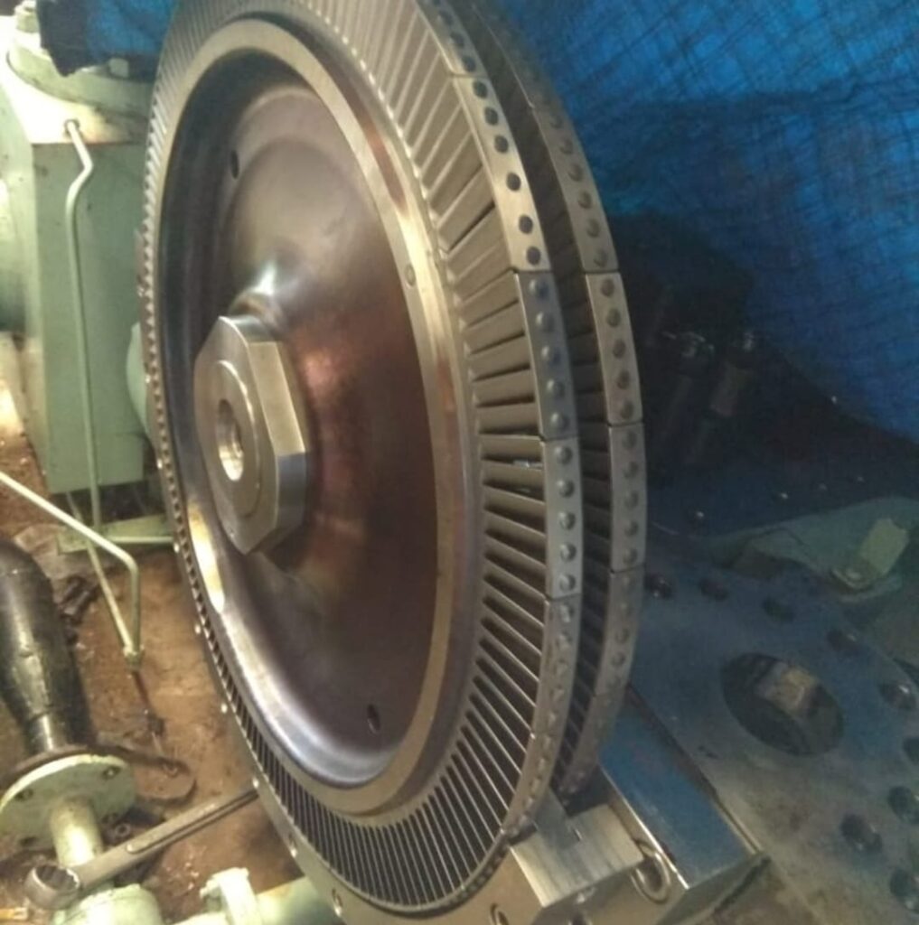
A biomass turbine generator is a central component of modern renewable energy systems that converts the thermal energy produced from biomass combustion or gasification into mechanical energy and, ultimately, electricity, forming a crucial part of biomass power plants, combined heat and power (CHP) systems, and waste-to-energy facilities. The operation begins with the collection, sorting, and preparation of biomass feedstocks, including agricultural residues such as straw, corn stalks, husks, and cobs, forestry by-products like wood chips, sawdust, and bark, municipal green waste, food processing residues, and selected industrial organic by-products. Feedstock quality is critical, as moisture content, particle size, density, and calorific value directly affect boiler or gasifier performance, turbine efficiency, and overall plant output. Preprocessing equipment—including shredders, grinders, trommels, and dryers—is used to create a uniform, consistent fuel suitable for continuous feeding into the combustion or gasification system. Automated hoppers, conveyors, and metered feeding mechanisms maintain a steady, controlled supply of feedstock, ensuring uninterrupted energy generation and stable thermal conditions for turbine operation.
In a biomass power system, thermal energy is first produced either by direct combustion of biomass in high-efficiency boilers or by gasification to produce syngas. The high-pressure steam or hot gas generated drives a turbine rotor connected to a generator, converting mechanical energy into electricity. Steam turbines are commonly used in biomass-fired plants where water is heated in a boiler to superheated or saturated steam conditions; this steam expands through the turbine blades, spinning the rotor to generate electricity. Alternatively, in gasification-based systems, biomass is converted into combustible syngas, which can be burned in a gas turbine to produce high-temperature, high-pressure exhaust gases that drive the turbine rotor. In some configurations, combined cycle systems capture residual heat from gas turbine exhaust to produce steam for a secondary steam turbine, further increasing overall plant efficiency. The design of the turbine—including blade geometry, rotor speed, and materials—is optimized to handle variable steam or gas conditions, moisture content, and particulate levels inherent in biomass-derived energy.
The efficiency and reliability of biomass turbine generators rely on precise thermal management, emission control, and operational monitoring. Heat recovery systems capture residual thermal energy from exhaust gases and turbine cooling circuits, redirecting it to preheat feedwater, supply district heating, or provide process heat for industrial applications. Advanced filtration and cleaning systems remove particulates, tars, and other impurities from biomass combustion or syngas streams before entering the turbine, preventing erosion, fouling, or corrosion of turbine blades and ensuring long-term operational reliability. Digital control systems continuously monitor turbine speed, rotor vibration, steam or gas pressure, temperature, and fuel flow rates, enabling real-time adjustments that optimize electrical output, maintain stable operation, and prevent damage due to overload or sudden variations in feedstock properties. Safety systems manage risks associated with high-pressure steam, hot gases, and combustible fuels, while predictive maintenance, remote monitoring, and automated fault detection enhance system uptime and operational reliability.
Residue and by-product handling is an integral part of biomass turbine generator systems. Ash from combustion or slag from gasification is collected, treated, and either safely disposed of or repurposed, for example as construction material, soil amendment, or road base. In gasification systems, tar, char, and other by-products are separated and processed to prevent contamination of turbines and generators. Robust storage, handling, and logistics systems, including silos, conveyors, hoppers, and trucks, ensure a continuous feedstock supply while facilitating efficient management of residues, reducing labor requirements, and minimizing operational interruptions.
Modern biomass turbine generators are increasingly integrated into hybrid energy systems and digital energy management platforms to optimize performance, increase energy recovery, and reduce environmental impact. Hybrid configurations may combine biomass turbines with steam turbines, gas turbines, or engines to enhance flexibility, maximize efficiency, and allow operation under varying feedstock types, moisture levels, and chemical compositions. Predictive analytics and automated process controls enable real-time optimization of turbine performance, fuel consumption, and emissions control, while integration with CHP networks or industrial processes allows the plant to simultaneously supply electricity and heat. By converting diverse biomass feedstocks into reliable electricity while capturing residual thermal energy, biomass turbine generators support circular economy principles, reduce reliance on fossil fuels, lower greenhouse gas emissions, and provide scalable renewable energy solutions for industrial, municipal, and agricultural applications.
Through the careful coordination of feedstock preparation, thermal energy generation, turbine operation, electricity generation, heat recovery, emissions control, residue handling, and digital monitoring, biomass turbine generators transform low-value organic materials into high-value electrical energy while supporting sustainable energy management. These systems exemplify the integration of renewable energy production and waste management, providing continuous, reliable electricity alongside thermal energy for industrial and municipal uses. Ongoing advancements in turbine design, combustion and gasification technologies, heat recovery, emissions mitigation, and digital process optimization continue to enhance efficiency, reliability, and environmental performance, establishing biomass turbine generators as a cornerstone of modern renewable energy infrastructure. By converting biomass into clean, high-efficiency electrical energy and thermal output, these systems play a critical role in reducing carbon emissions, supporting low-carbon energy strategies, and promoting circular resource utilization in industrial, municipal, and agricultural applications.
A biomass turbine generator is a highly specialized and integrated system designed to convert the thermal energy derived from biomass combustion or gasification into mechanical energy and ultimately electricity, serving as a core component of biomass power plants, combined heat and power (CHP) facilities, and waste-to-energy operations. The process begins with the careful selection, reception, sorting, and storage of biomass feedstocks, which may include agricultural residues such as straw, corn stalks, husks, and cobs, forestry by-products like wood chips, sawdust, bark, and small branches, municipal green waste, food processing residues, and selected organic industrial by-products. The physical and chemical properties of the feedstock—moisture content, particle size, density, and calorific value—directly influence combustion efficiency, turbine performance, and overall electricity output, making preprocessing a critical step. Biomass is typically shredded, ground, screened, and dried to ensure uniformity and consistent fuel quality, while automated hoppers, conveyors, and metered feeders provide a continuous and controlled supply to the combustion or gasification unit, preventing interruptions and maintaining stable thermal conditions for the turbine generator.
In a biomass power system, thermal energy is produced either through direct combustion of solid biomass in high-efficiency boilers or via gasification that converts biomass into combustible syngas. In combustion-based systems, water is heated in boilers to produce superheated or saturated steam, which expands through the turbine blades, causing the rotor to spin and drive the coupled generator to produce electricity. In gasification-based systems, syngas composed of carbon monoxide, hydrogen, and methane is combusted in a gas turbine, producing high-pressure, high-temperature exhaust gases that drive the turbine rotor. Advanced configurations often incorporate combined cycle systems, where residual heat from gas turbine exhaust is captured to produce steam for a secondary steam turbine, significantly improving overall plant efficiency. Turbine design, including blade geometry, rotor speed, material selection, and cooling methods, is carefully optimized to handle variable steam or gas conditions and to resist the erosive and corrosive effects of impurities present in biomass-derived energy streams.
The operational efficiency and reliability of biomass turbine generators rely on sophisticated thermal management, emissions control, and automated process monitoring. Heat recovery systems capture residual energy from turbine exhaust, flue gases, or engine cooling circuits and redirect it to preheat feedwater, supply district heating, or provide process heat for industrial applications, thereby maximizing the usable energy extracted from biomass. Advanced filtration systems remove particulates, tars, and other contaminants from the fuel or gas streams to prevent erosion, fouling, or corrosion of turbine components, ensuring long-term operational reliability. Modern digital control systems monitor turbine speed, rotor vibration, steam or gas pressure, temperature, and fuel flow rates in real time, enabling precise adjustments that optimize electricity generation, maintain system stability, and protect against overloads or sudden variations in feedstock properties. Safety systems are implemented to mitigate risks associated with high-pressure steam, hot gases, and combustible fuels, while predictive maintenance, remote monitoring, and automated fault detection reduce downtime and extend the operational life of critical equipment.
Residue management is an essential component of biomass turbine generator systems. Combustion produces bottom ash and fly ash, while gasification produces char, tar, and other residues. These by-products must be collected, treated, and either safely disposed of or repurposed. Bottom ash can be reused as construction material or road base, while fly ash and tars are carefully managed to prevent environmental contamination. Storage, handling, and logistics systems, including silos, hoppers, conveyors, and trucks, ensure a continuous feedstock supply while facilitating the efficient collection, transport, and processing of residues, minimizing labor requirements and preventing operational bottlenecks. Some advanced biomass power plants employ hybrid systems that combine gas turbines, steam turbines, and reciprocating engines to increase operational flexibility, maximize energy recovery, and handle diverse feedstocks with varying moisture levels, particle sizes, and chemical compositions.
Integration with digital energy management platforms and predictive analytics further enhances the efficiency, environmental performance, and reliability of biomass turbine generator systems. Real-time monitoring and automated process control optimize fuel consumption, electricity generation, heat recovery, and emissions management, while hybrid configurations allow the plant to simultaneously provide electricity, district heating, and process steam. By converting organic waste streams into renewable electricity and heat, biomass turbine generators support circular economy principles, reduce reliance on fossil fuels, lower greenhouse gas emissions, and provide a scalable and sustainable energy solution for industrial, municipal, and agricultural applications.
Through the seamless integration of feedstock handling, thermal energy generation, turbine operation, electricity conversion, heat recovery, emissions control, residue management, and digital monitoring, biomass turbine generators transform low-value organic materials into high-value electrical energy while providing heat for industrial, commercial, or municipal use. These systems exemplify the intersection of renewable energy generation and sustainable waste management, delivering continuous and reliable electricity and thermal energy with minimal environmental impact. With ongoing advancements in turbine design, gasification and combustion technologies, heat recovery strategies, emissions mitigation, and digital process optimization, biomass turbine generator systems continue to increase in efficiency, reliability, and sustainability. By maximizing the energy potential of diverse biomass feedstocks, these systems play a critical role in low-carbon energy strategies, circular resource management, and renewable energy infrastructure, providing versatile, environmentally responsible, and economically viable solutions for modern energy needs.
A biomass turbine generator represents a sophisticated and highly integrated energy solution designed to convert the thermal energy derived from biomass into mechanical energy and, ultimately, electrical power, forming a crucial part of renewable energy infrastructure in biomass power plants, combined heat and power (CHP) systems, and waste-to-energy facilities. The operation begins with the careful selection, collection, sorting, and storage of biomass feedstocks, which can include a wide variety of organic materials such as agricultural residues like straw, corn stalks, husks, and cobs; forestry by-products including wood chips, sawdust, bark, and small branches; municipal green waste; food processing residues; and certain industrial organic by-products. The moisture content, particle size, density, and calorific value of these feedstocks play a critical role in determining combustion efficiency, gasification performance, turbine output, and overall energy generation, making preprocessing a vital step in the process. Shredders, grinders, trommels, and dryers are employed to produce a uniform and manageable fuel suitable for continuous feeding, while automated hoppers, conveyors, and metered feeders ensure a consistent supply of biomass into the combustion or gasification system, maintaining stable thermal conditions essential for turbine operation and preventing interruptions that could reduce efficiency or cause operational issues.
Once the biomass is prepared, the energy conversion process begins through either direct combustion in high-efficiency boilers or gasification to produce syngas. In combustion-based systems, water is heated to produce high-pressure steam, which expands through the blades of a steam turbine connected to a generator, converting thermal energy into mechanical and then electrical energy. In gasification-based systems, biomass is converted into a combustible syngas mixture of carbon monoxide, hydrogen, and methane, which is then burned in a gas turbine, producing high-temperature, high-pressure gases that drive the turbine rotor. Many modern plants employ combined cycle configurations, capturing residual heat from gas turbine exhaust to produce steam for secondary steam turbines, thereby significantly improving overall plant efficiency. Turbine design is carefully engineered to accommodate the specific properties of biomass-derived energy, including variable steam or gas temperatures, pressures, and potential particulates or tars, with attention to blade geometry, rotor speed, material selection, and cooling methods to ensure long-term reliability and optimal performance.
The efficiency and sustainability of biomass turbine generators depend on sophisticated thermal management, emissions control, and digital process monitoring. Heat recovery systems capture residual energy from turbine exhaust, flue gases, and engine cooling circuits, redirecting it to preheat boiler feedwater, dry incoming biomass feedstock, or supply district heating and industrial process heat. Advanced gas cleaning and filtration technologies remove particulates, tars, and other impurities from combustion or syngas streams, protecting turbine components from erosion, corrosion, and fouling, and ensuring reliable, long-term operation. Real-time digital monitoring tracks critical operational parameters such as turbine speed, rotor vibration, steam or gas pressure, temperature, and fuel flow, enabling automated adjustments that maintain stable electricity generation, optimize efficiency, and prevent mechanical or thermal stress. Safety systems are integrated to manage risks associated with high-pressure steam, flammable gases, combustible dust, and mechanical failure, while predictive maintenance, remote diagnostics, and automated fault detection enhance reliability and minimize downtime.
Residue and by-product management is an essential aspect of biomass turbine generator operations. Combustion produces bottom ash and fly ash, while gasification produces char, tar, and other by-products that must be properly collected, treated, and either safely disposed of or repurposed. Bottom ash can often be utilized in construction, road base, or other industrial applications, while fly ash and tars are managed to mitigate environmental risks. Robust storage, handling, and logistics infrastructure, including silos, hoppers, conveyors, and transport vehicles, ensures a continuous feedstock supply and efficient handling of combustion or gasification residues, reducing labor requirements and preventing operational bottlenecks. Advanced biomass power plants increasingly employ hybrid configurations, combining gas turbines, steam turbines, and engines to increase operational flexibility, maximize energy recovery, and handle diverse feedstocks with varying moisture levels, particle sizes, and chemical compositions.
Integration with digital energy management platforms and predictive analytics further improves the operational efficiency, environmental performance, and reliability of biomass turbine generator systems. Real-time monitoring and automated control allow precise optimization of fuel consumption, electricity output, heat recovery, and emissions mitigation, while hybrid systems enable simultaneous generation of electricity, district heating, and process steam. By converting a wide range of biomass feedstocks into reliable electricity while utilizing residual thermal energy, these systems promote circular economy principles, reduce dependence on fossil fuels, lower greenhouse gas emissions, and provide scalable renewable energy solutions for industrial, municipal, and agricultural applications.
Through the seamless integration of feedstock handling, thermal energy generation, turbine operation, electricity conversion, heat recovery, emissions control, residue management, and digital monitoring, biomass turbine generators transform low-value organic materials into high-value electrical energy while simultaneously supplying heat for industrial, commercial, or municipal purposes. These systems exemplify the intersection of renewable energy production and sustainable waste management, delivering continuous and reliable electricity alongside thermal energy with minimal environmental impact. Ongoing advancements in turbine design, combustion and gasification technologies, heat recovery systems, emissions mitigation strategies, hybrid configurations, and process automation continue to enhance the efficiency, reliability, and sustainability of biomass turbine generators. By maximizing the energy potential of diverse biomass feedstocks, these systems play a critical role in low-carbon energy strategies, circular resource management, and modern renewable energy infrastructure, providing versatile, environmentally responsible, and economically viable solutions for energy production across industrial, municipal, and agricultural sectors.
A biomass turbine generator is a highly advanced and integrated energy conversion system designed to transform the chemical energy stored in biomass into mechanical energy and subsequently into electricity, forming a cornerstone of modern biomass power plants, combined heat and power (CHP) facilities, and waste-to-energy installations. The process begins with the reception, sorting, storage, and preprocessing of biomass feedstocks, which may include agricultural residues such as straw, corn stalks, husks, and cobs, forestry by-products like wood chips, sawdust, bark, and small branches, municipal green waste, food processing residues, and selected industrial organic by-products. Each type of feedstock has unique physical and chemical characteristics, including moisture content, particle size, density, calorific value, and ash content, all of which significantly influence combustion efficiency, gasification performance, turbine operation, and overall electrical output. Preprocessing equipment such as shredders, grinders, trommels, and dryers is employed to create a uniform fuel material, while automated hoppers, metered conveyors, and feeding mechanisms maintain a steady and controlled supply of biomass into the combustion or gasification unit, ensuring consistent thermal conditions for the turbine generator and preventing fluctuations that could compromise efficiency or reliability.
Once the biomass is prepared, the energy conversion process begins, either through direct combustion in high-efficiency boilers or via gasification, which converts biomass into a combustible syngas mixture of carbon monoxide, hydrogen, and methane. In steam turbine-based systems, water is heated to generate high-pressure steam that expands through the turbine blades, spinning the rotor and driving a generator to produce electricity. In gasification-based systems, the syngas is combusted in a gas turbine, producing high-temperature, high-pressure gases that rotate the turbine rotor. Many modern installations employ combined cycle configurations, where the residual heat from the gas turbine exhaust is recovered to generate steam for a secondary steam turbine, significantly improving overall plant efficiency. Turbine design—including blade geometry, rotor speed, material selection, and cooling techniques—is carefully optimized to handle variable steam or gas conditions, moisture content, particulate load, and potential corrosive elements, ensuring long-term operational reliability and maximum performance.
Operational efficiency and sustainability of biomass turbine generators rely on precise thermal management, emissions control, and advanced process monitoring. Heat recovery systems capture residual energy from turbine exhaust, flue gases, and cooling circuits, redirecting it to preheat boiler feedwater, dry incoming biomass feedstock, or supply district heating and industrial process heat, maximizing the usable energy derived from biomass. Advanced filtration and cleaning systems remove particulates, tars, and other impurities from combustion or syngas streams, protecting turbine blades, rotors, and internal components from erosion, fouling, and corrosion, ensuring continuous, long-term operation. Digital monitoring systems track turbine speed, rotor vibration, steam or gas pressure, temperature, and fuel flow rates in real time, allowing automated adjustments to optimize electricity generation, maintain operational stability, and protect against mechanical or thermal stresses. Safety systems are integrated to address high-pressure steam, flammable gases, combustible dust, and mechanical risks, while predictive maintenance, remote monitoring, and automated fault detection enhance reliability and minimize downtime.
Residue and by-product management is a critical aspect of biomass turbine generator operations. Combustion produces bottom ash and fly ash, while gasification produces char, tar, and other by-products. These residues must be collected, processed, and either safely disposed of or repurposed; bottom ash can be used in construction or road building, while fly ash and tar residues are carefully treated to reduce environmental impact. Storage, handling, and logistics infrastructure, including silos, hoppers, conveyors, and transport vehicles, ensures a continuous supply of feedstock and efficient management of residues, reducing labor needs and minimizing operational bottlenecks. Many advanced biomass power plants employ hybrid configurations combining gas turbines, steam turbines, and reciprocating engines, enhancing operational flexibility, increasing energy recovery, and allowing the plant to efficiently process diverse feedstocks with varying moisture contents, particle sizes, and chemical compositions.
Integration with digital energy management platforms and predictive analytics further enhances the performance, environmental sustainability, and reliability of biomass turbine generator systems. Automated controls allow precise optimization of fuel usage, electricity production, heat recovery, and emissions management, while hybrid configurations enable simultaneous supply of electricity, process steam, and district heating. By converting diverse organic feedstocks into renewable electricity and capturing residual thermal energy, biomass turbine generators reduce reliance on fossil fuels, support circular economy principles, lower greenhouse gas emissions, and provide scalable energy solutions for industrial, municipal, and agricultural applications.
Through the coordinated integration of feedstock handling, thermal energy generation, turbine operation, electricity conversion, heat recovery, emissions control, residue management, and digital monitoring, biomass turbine generators transform low-value organic waste into high-value electricity while providing thermal energy for industrial, commercial, or municipal use. These systems exemplify the combination of renewable energy generation and sustainable waste management, delivering continuous and reliable electricity alongside usable heat with minimal environmental impact. Ongoing advancements in turbine design, combustion and gasification technologies, heat recovery methods, emissions control strategies, hybrid system integration, and process automation continue to improve the efficiency, reliability, and sustainability of biomass turbine generators. By maximizing the energy potential of diverse biomass feedstocks, these systems play a pivotal role in low-carbon energy strategies, circular resource management, and modern renewable energy infrastructure, offering versatile, environmentally responsible, and economically viable energy solutions across industrial, municipal, and agricultural sectors.
Biomass Heat Exchanger Plant
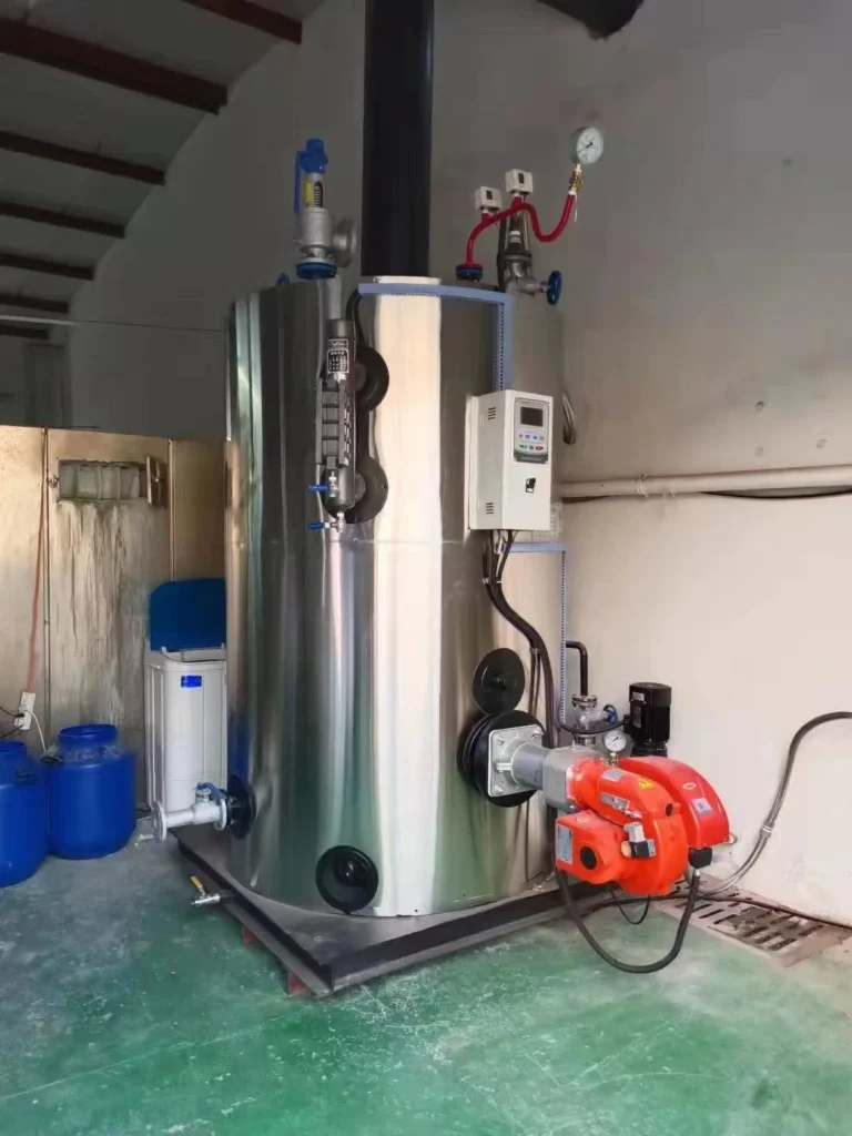
A biomass heat exchanger plant is an essential component of renewable energy systems that efficiently transfers the thermal energy generated from biomass combustion, gasification, or pyrolysis into usable heat for industrial processes, district heating networks, and combined heat and power (CHP) applications, maximizing the energy extracted from biomass while minimizing losses. The system begins with the careful selection, reception, sorting, and storage of biomass feedstocks, which can include agricultural residues such as straw, corn stalks, husks, and cobs, forestry by-products like wood chips, sawdust, bark, and small branches, municipal green waste, food processing residues, and selected organic industrial by-products. The physical and chemical characteristics of the feedstock, including moisture content, particle size, density, calorific value, and ash content, have a significant impact on combustion efficiency, thermal transfer rates, and overall energy output. Preprocessing equipment such as shredders, grinders, trommels, and dryers is used to produce a uniform fuel material, while automated hoppers, metered conveyors, and feeders ensure a steady and controlled supply of biomass to the combustion or gasification unit, maintaining consistent thermal conditions for optimal heat exchange.
Once the biomass is combusted or gasified, thermal energy is transferred through the heat exchanger system, which serves as the critical interface between the energy source and the application requiring heat. In a biomass heat exchanger plant, high-temperature gases, steam, or hot water generated by the combustion or gasification process pass through a series of heat exchange surfaces, including tubes, plates, or coils, allowing heat to be efficiently transferred to water, thermal oils, or air, depending on the design and intended application. The design of the heat exchangers—including surface area, material selection, flow configuration, and temperature gradients—is optimized to handle the variable composition of biomass-derived flue gases, prevent fouling and corrosion, and maximize thermal transfer efficiency. Advanced designs may include multi-pass, counterflow, or shell-and-tube configurations to enhance heat recovery and ensure uniform distribution of energy.
Thermal management and operational efficiency are key considerations in biomass heat exchanger plants. Heat recovery systems capture residual energy from flue gases or exhaust streams, preheating boiler feedwater, drying incoming biomass feedstock, or supplying district heating or industrial process heat, reducing fuel consumption and maximizing the energy extracted from the biomass. Advanced filtration and cleaning systems remove particulates, tars, and corrosive components from the flue gas stream before it enters the heat exchanger, protecting the surfaces from erosion, fouling, and corrosion, and ensuring long-term operational reliability. Digital monitoring systems track critical parameters such as inlet and outlet temperatures, pressure drops, flow rates, and heat transfer efficiency, enabling real-time adjustments that optimize performance, maintain steady heat output, and prevent equipment damage. Safety systems are integrated to manage high-pressure steam, flammable gases, and hot fluids, while predictive maintenance and automated diagnostics reduce unplanned downtime and extend equipment life.
Residue and by-product management is also an integral aspect of biomass heat exchanger plants. Combustion produces bottom ash and fly ash, while gasification can produce char and tar residues, all of which must be collected, processed, and either safely disposed of or repurposed. Ash can be used in construction, road building, or other industrial applications, while tar and other residues are carefully treated to mitigate environmental risks. Storage, handling, and logistics systems—including silos, hoppers, conveyors, and trucks—ensure a continuous biomass supply and efficient management of residues, minimizing labor requirements and operational interruptions.
Modern biomass heat exchanger plants are increasingly integrated with CHP systems, digital energy management platforms, and predictive analytics to maximize efficiency, environmental performance, and reliability. Real-time monitoring and automated control allow precise optimization of heat transfer, fuel consumption, and emissions management, while hybrid configurations enable simultaneous generation of heat, electricity, and steam. By efficiently converting biomass feedstocks into usable thermal energy, heat exchanger plants reduce reliance on fossil fuels, support circular economy principles, lower greenhouse gas emissions, and provide scalable renewable energy solutions for industrial, municipal, and agricultural applications.
Through the coordinated integration of feedstock handling, combustion or gasification, thermal energy transfer, emissions control, residue management, and digital monitoring, biomass heat exchanger plants transform low-value organic materials into high-value thermal energy, supplying heat for industrial, commercial, and municipal applications. These systems exemplify the synergy between renewable energy generation and sustainable waste management, providing continuous and reliable heat while minimizing environmental impact. Ongoing advancements in heat exchanger design, materials, fouling mitigation, thermal recovery strategies, emissions control, hybrid integration, and process automation continue to improve the efficiency, reliability, and sustainability of biomass heat exchanger plants. By maximizing the thermal energy potential of diverse biomass feedstocks, these systems play a critical role in low-carbon energy strategies, circular resource management, and modern renewable energy infrastructure, offering versatile, environmentally responsible, and economically viable heat solutions across industrial, municipal, and agricultural sectors.
A biomass heat exchanger plant is a sophisticated energy facility designed to efficiently transfer thermal energy derived from biomass combustion, gasification, or pyrolysis into usable heat for industrial processes, district heating networks, and combined heat and power (CHP) applications, maximizing energy extraction from biomass while minimizing losses. The operation begins with the careful collection, sorting, storage, and preprocessing of biomass feedstocks, which may include agricultural residues such as straw, corn stalks, husks, and cobs, forestry by-products including wood chips, sawdust, bark, and small branches, municipal green waste, food processing residues, and selected industrial organic by-products. Each feedstock type possesses unique physical and chemical properties, including moisture content, particle size, density, calorific value, and ash content, which directly impact combustion efficiency, heat transfer performance, and overall plant output. Preprocessing equipment such as shredders, grinders, trommels, and dryers is used to produce a uniform fuel material, while automated hoppers, metered conveyors, and feeders ensure a consistent supply of biomass to the combustion or gasification unit, maintaining steady thermal conditions that are critical for optimal heat exchanger performance and preventing fluctuations that could reduce efficiency or compromise system reliability.
Once the biomass is prepared, the thermal energy generated through combustion or gasification is transferred via the heat exchanger system, which serves as the interface between the energy source and the application requiring heat. In these plants, high-temperature flue gases, steam, or hot water pass through a series of heat exchange surfaces—tubes, plates, or coils—allowing the thermal energy to be efficiently imparted to water, thermal oils, or air depending on the intended application. The design of the heat exchangers—including surface area, material selection, flow configuration, and temperature gradients—is optimized to handle variable compositions of biomass-derived flue gases while minimizing fouling, corrosion, and heat loss, ensuring maximum thermal transfer efficiency. Advanced designs often incorporate multi-pass, counterflow, shell-and-tube, or plate-type configurations to enhance heat recovery and ensure uniform energy distribution throughout the system, providing consistent output for industrial processes, district heating, or CHP networks.
Thermal management and operational optimization are central to the performance of biomass heat exchanger plants. Heat recovery systems capture residual energy from flue gases, exhaust streams, and boiler surfaces, redirecting it to preheat incoming biomass, feedwater, or thermal oil circuits, or to supply district heating networks and industrial process heat, thereby maximizing overall energy utilization and minimizing fuel consumption. Sophisticated filtration and cleaning technologies remove particulates, tars, and corrosive components from the flue gas stream before it enters the heat exchanger, protecting surfaces from erosion, fouling, and chemical degradation, and ensuring long-term operational reliability. Digital monitoring and control systems continuously track critical operational parameters, including inlet and outlet temperatures, pressure drops, flow rates, and heat transfer efficiency, enabling real-time adjustments that optimize energy transfer, maintain steady heat output, and prevent equipment damage. Safety systems address risks associated with high-pressure steam, flammable gases, hot fluids, and potential mechanical failures, while predictive maintenance and automated diagnostics minimize downtime and extend the service life of components.
Residue and by-product management is an integral part of biomass heat exchanger plant operation. Combustion produces bottom ash and fly ash, while gasification generates char, tar, and other by-products, all of which must be collected, processed, and either safely disposed of or repurposed. Bottom ash can be reused in construction, road building, or other industrial applications, while fly ash and tar residues are treated to reduce environmental impact. Comprehensive storage, handling, and logistics infrastructure—including silos, hoppers, conveyors, and transport vehicles—ensures a continuous feedstock supply and efficient residue management, minimizing labor requirements and preventing operational bottlenecks. Advanced plants may also incorporate hybrid systems combining biomass boilers, gasifiers, and heat exchangers to enhance energy efficiency, increase operational flexibility, and allow for the processing of diverse feedstocks with varying moisture contents, particle sizes, and calorific values.
Modern biomass heat exchanger plants are increasingly integrated with digital energy management platforms, predictive analytics, and combined heat and power systems to maximize efficiency, environmental performance, and reliability. Real-time monitoring and automated control allow precise optimization of heat transfer rates, fuel consumption, emissions, and system performance, while hybrid configurations enable simultaneous generation of heat, electricity, and steam, depending on operational requirements. By efficiently converting biomass feedstocks into usable thermal energy, heat exchanger plants reduce reliance on fossil fuels, support circular economy principles, lower greenhouse gas emissions, and provide scalable, renewable energy solutions for industrial, municipal, and agricultural applications.
Through the seamless integration of feedstock handling, combustion or gasification, thermal energy transfer, emissions control, residue management, and digital monitoring, biomass heat exchanger plants transform low-value organic materials into high-value thermal energy, providing continuous and reliable heat for industrial, commercial, and municipal applications. These systems exemplify the synergy between renewable energy generation and sustainable waste management, enabling the conversion of diverse organic waste streams into efficient heat with minimal environmental impact. Continuous advancements in heat exchanger design, materials, fouling mitigation, thermal recovery strategies, emissions control, hybrid system integration, and process automation are increasing the efficiency, reliability, and sustainability of biomass heat exchanger plants. By maximizing the thermal energy potential of diverse biomass feedstocks, these systems play a critical role in low-carbon energy strategies, circular resource management, and modern renewable energy infrastructure, offering versatile, environmentally responsible, and economically viable heat solutions for a wide range of industrial, municipal, and agricultural applications.
A biomass heat exchanger plant is an advanced and highly integrated energy facility designed to efficiently transfer the thermal energy produced from biomass combustion, gasification, or pyrolysis into usable heat for industrial processes, district heating, and combined heat and power (CHP) applications, ensuring maximum utilization of the energy content of biomass while minimizing losses and environmental impact. The system begins with the careful collection, reception, sorting, and storage of diverse biomass feedstocks, including agricultural residues such as straw, corn stalks, husks, and cobs; forestry by-products like wood chips, sawdust, bark, and small branches; municipal green waste; food processing residues; and certain industrial organic by-products. Each type of feedstock has unique physical and chemical properties, including moisture content, particle size, density, calorific value, and ash composition, all of which significantly affect combustion performance, heat transfer efficiency, and overall plant output. Preprocessing equipment—including shredders, grinders, trommels, and dryers—is employed to produce a uniform, consistent fuel material, while automated hoppers, conveyors, and metered feeding systems maintain a steady, controlled supply of biomass to the combustion or gasification unit, preventing fluctuations in thermal input that could reduce efficiency or compromise system reliability.
Once biomass is processed, it is converted into high-temperature energy through combustion or gasification. In the case of combustion, biomass is burned in high-efficiency boilers to produce hot flue gases or steam, which are then directed through heat exchangers to transfer energy to water, thermal oils, or air for use in industrial processes, district heating, or CHP networks. In gasification-based systems, biomass is converted into a combustible syngas containing carbon monoxide, hydrogen, and methane, which is combusted to generate high-temperature gases that pass through heat exchanger surfaces to impart thermal energy efficiently. The design of the heat exchangers—including material selection, surface area, flow configuration, and temperature gradient management—is optimized to handle the variable composition of biomass-derived flue gases, prevent fouling, corrosion, and erosion, and maximize heat transfer efficiency. Advanced designs often incorporate multi-pass, counterflow, shell-and-tube, or plate configurations to ensure uniform energy distribution and minimal thermal losses, accommodating the variations in temperature, gas composition, and particulate content characteristic of biomass energy streams.
Thermal management and operational efficiency are critical in biomass heat exchanger plants. Heat recovery systems capture residual energy from flue gases, exhaust streams, and boiler surfaces, redirecting it to preheat incoming biomass, feedwater, or thermal oil circuits, or supplying district heating or industrial process heat, thereby reducing fuel consumption and maximizing overall energy utilization. Sophisticated filtration and cleaning systems remove particulates, tars, and corrosive components from the flue gas or syngas before it enters the heat exchanger, protecting surfaces from erosion, fouling, and chemical degradation and ensuring long-term operational reliability. Modern digital monitoring systems continuously track key operational parameters such as inlet and outlet temperatures, pressure drops, flow rates, and heat transfer efficiency, enabling real-time adjustments to optimize energy transfer, maintain stable heat output, and prevent equipment damage. Safety systems are incorporated to manage high-pressure steam, hot fluids, flammable gases, and potential mechanical failures, while predictive maintenance, automated diagnostics, and remote monitoring reduce downtime and prolong equipment lifespan.
Residue and by-product handling is an integral part of biomass heat exchanger plant operation. Combustion produces bottom ash and fly ash, while gasification generates char, tar, and other residues, all of which must be collected, processed, and either safely disposed of or repurposed. Bottom ash can often be used in construction, road building, or other industrial applications, while fly ash, tar, and other by-products are treated to mitigate environmental risks. Comprehensive storage, handling, and logistics systems—including silos, hoppers, conveyors, and transport vehicles—ensure a continuous supply of feedstock and efficient management of residues, reducing labor requirements and minimizing operational bottlenecks. Many modern plants also incorporate hybrid systems that combine biomass boilers, gasifiers, and heat exchangers to improve overall energy efficiency, increase operational flexibility, and allow for the processing of diverse feedstocks with varying moisture content, particle size, and calorific value.
Integration with digital energy management platforms and predictive analytics further enhances the efficiency, environmental performance, and reliability of biomass heat exchanger plants. Automated control systems allow precise optimization of heat transfer, fuel consumption, and emissions management, while hybrid configurations enable simultaneous generation of heat, electricity, and process steam to meet varying energy demands. By efficiently converting biomass feedstocks into usable thermal energy, heat exchanger plants reduce dependence on fossil fuels, support circular economy principles, lower greenhouse gas emissions, and provide scalable renewable energy solutions for industrial, municipal, and agricultural applications.
Through the coordinated integration of feedstock handling, combustion or gasification, thermal energy transfer, emissions control, residue management, and digital monitoring, biomass heat exchanger plants transform low-value organic materials into high-value thermal energy, providing continuous and reliable heat for industrial, commercial, and municipal uses. These systems exemplify the synergy between renewable energy generation and sustainable waste management, converting diverse organic waste streams into efficient, usable heat while minimizing environmental impact. Ongoing advancements in heat exchanger design, materials, fouling mitigation, thermal recovery strategies, emissions control, hybrid system integration, and process automation continue to improve the efficiency, reliability, and sustainability of biomass heat exchanger plants. By maximizing the thermal energy potential of a wide range of biomass feedstocks, these plants play a pivotal role in low-carbon energy strategies, circular resource management, and modern renewable energy infrastructure, providing versatile, environmentally responsible, and economically viable solutions for heat production across industrial, municipal, and agricultural sectors.
A biomass heat exchanger plant is a highly integrated and sophisticated energy facility designed to efficiently convert the thermal energy produced from the combustion, gasification, or pyrolysis of biomass into usable heat for a wide range of applications, including industrial processes, district heating networks, and combined heat and power (CHP) systems, maximizing energy utilization while minimizing environmental impact. The operation begins with the reception, sorting, storage, and preprocessing of biomass feedstocks, which can include agricultural residues such as straw, corn stalks, husks, and cobs; forestry by-products like wood chips, sawdust, bark, and branches; municipal green waste; food processing residues; and selected industrial organic by-products. Each type of feedstock has unique physical and chemical characteristics, including moisture content, particle size, density, calorific value, and ash composition, all of which directly influence combustion efficiency, heat transfer performance, and overall plant output. Preprocessing equipment such as shredders, grinders, trommels, and dryers is used to create a uniform, manageable fuel, while automated hoppers, conveyors, and metered feeders ensure a steady and controlled supply of biomass to the combustion or gasification units, maintaining stable thermal conditions that are critical for optimal heat exchanger performance and preventing fluctuations that could reduce efficiency or compromise system reliability.
Once the biomass is prepared, it is converted into high-temperature thermal energy through combustion or gasification. In combustion-based systems, biomass is burned in high-efficiency boilers to generate hot flue gases or steam, which are then directed through heat exchangers to transfer energy to water, thermal oils, or air, depending on the intended application. In gasification-based systems, biomass is converted into syngas composed of carbon monoxide, hydrogen, and methane, which is combusted to produce high-temperature gases that pass through heat exchanger surfaces, transferring thermal energy efficiently. The design of the heat exchangers—including material selection, surface area, flow configuration, and management of temperature gradients—is optimized to handle the variable composition of biomass-derived flue gases, resist fouling, erosion, and corrosion, and maximize thermal transfer efficiency. Advanced designs often incorporate multi-pass, counterflow, shell-and-tube, or plate-type configurations to ensure uniform heat distribution, minimal losses, and consistent output for industrial processes, district heating, or CHP applications, accommodating variations in temperature, gas composition, and particulate load inherent in biomass energy streams.
Thermal management and operational efficiency are central to biomass heat exchanger plant performance. Heat recovery systems capture residual energy from flue gases, exhaust streams, and boiler surfaces, redirecting it to preheat incoming biomass, feedwater, or thermal oil circuits or to supply district heating and industrial process heat, reducing fuel consumption and increasing overall energy efficiency. Advanced filtration and cleaning technologies remove particulates, tars, and corrosive components from the flue gas or syngas before it enters the heat exchanger, protecting surfaces from erosion, fouling, and chemical degradation, and ensuring long-term operational reliability. Digital monitoring and automated control systems continuously track operational parameters such as inlet and outlet temperatures, pressure drops, flow rates, and heat transfer efficiency, enabling real-time adjustments to maintain stable output, optimize energy transfer, and prevent equipment damage. Safety systems manage high-pressure steam, flammable gases, hot fluids, and potential mechanical failures, while predictive maintenance, automated diagnostics, and remote monitoring reduce unplanned downtime and extend the operational lifespan of the plant.
Residue and by-product management is a critical aspect of biomass heat exchanger plant operation. Combustion produces bottom ash and fly ash, while gasification generates char, tar, and other residues, all of which must be collected, processed, and either safely disposed of or repurposed. Bottom ash is often recycled for construction materials, road building, or other industrial applications, while fly ash, tar, and other by-products are treated to mitigate environmental risks. Comprehensive storage, handling, and logistics systems—including silos, hoppers, conveyors, and transport vehicles—ensure a continuous supply of feedstock and efficient management of residues, reducing labor requirements and operational interruptions. Many modern biomass heat exchanger plants also employ hybrid configurations, combining biomass boilers, gasifiers, and heat exchangers to enhance overall energy efficiency, improve operational flexibility, and allow for the processing of diverse feedstocks with varying moisture content, particle sizes, and calorific values.
Integration with digital energy management platforms, predictive analytics, and CHP systems further improves the efficiency, reliability, and environmental performance of biomass heat exchanger plants. Automated control systems allow for precise optimization of heat transfer rates, fuel consumption, emissions mitigation, and overall system performance, while hybrid configurations enable simultaneous generation of heat, electricity, and process steam to meet diverse energy demands. By efficiently converting biomass feedstocks into usable thermal energy, heat exchanger plants reduce reliance on fossil fuels, support circular economy principles, lower greenhouse gas emissions, and provide scalable renewable energy solutions for industrial, municipal, and agricultural applications.
Through the seamless integration of feedstock handling, combustion or gasification, thermal energy transfer, emissions control, residue management, and digital monitoring, biomass heat exchanger plants transform low-value organic materials into high-value thermal energy, providing continuous and reliable heat for industrial, commercial, and municipal applications. These systems exemplify the synergy between renewable energy generation and sustainable waste management, converting a variety of organic waste streams into efficient, usable heat while minimizing environmental impact. Continuous advancements in heat exchanger design, materials, fouling mitigation, thermal recovery strategies, emissions control, hybrid system integration, and process automation are progressively improving the efficiency, reliability, and sustainability of biomass heat exchanger plants. By maximizing the thermal energy potential of diverse biomass feedstocks, these plants play a critical role in low-carbon energy strategies, circular resource management, and modern renewable energy infrastructure, offering versatile, environmentally responsible, and economically viable solutions for heat production across industrial, municipal, and agricultural sectors.
Biomass Furnace System
A biomass furnace system is a core component of renewable energy and waste-to-energy facilities, designed to efficiently convert the chemical energy stored in biomass feedstocks into thermal energy for industrial processes, district heating, or combined heat and power (CHP) applications. The system begins with the careful reception, sorting, storage, and preprocessing of a wide range of biomass materials, which may include agricultural residues such as straw, corn stalks, husks, and cobs; forestry by-products like wood chips, sawdust, bark, and small branches; municipal green waste; food processing residues; and selected industrial organic by-products. Each feedstock possesses unique physical and chemical characteristics, including moisture content, particle size, density, calorific value, and ash composition, all of which directly affect combustion efficiency, heat generation, and overall system performance. Preprocessing equipment such as shredders, grinders, trommels, and dryers is used to produce a uniform, consistent fuel suitable for controlled feeding into the furnace, while automated hoppers, conveyors, and metered feeding mechanisms ensure a steady supply, preventing fluctuations that could reduce thermal efficiency or cause operational instability.
Once the biomass is prepared, it enters the furnace system, where controlled combustion occurs to release thermal energy. Modern biomass furnaces are designed for high-efficiency combustion, incorporating advanced burner designs, air staging, and temperature control systems to ensure complete fuel burn, minimize unburned carbon, and reduce emissions of pollutants such as particulates, carbon monoxide, and nitrogen oxides. Depending on the system design, the furnace may operate under fixed-bed, moving-grate, fluidized-bed, or rotary combustion configurations, each tailored to specific feedstock types and moisture content ranges. Fixed-bed or grate furnaces are often used for uniform, solid biomass with low moisture content, allowing biomass to slowly combust on a stationary grate, while fluidized-bed furnaces provide more turbulent mixing, improved heat transfer, and tolerance for higher moisture or heterogeneous feedstocks. Rotary furnaces are capable of handling mixed and variable biomass materials, ensuring continuous combustion and uniform temperature distribution throughout the chamber.
Thermal energy generated in the biomass furnace is then transferred via heat exchange systems, where flue gases, hot water, or steam pass through heat exchanger surfaces, imparting energy to water, thermal oils, or air for use in industrial processes, district heating networks, or CHP systems. The design of these heat transfer surfaces is optimized to withstand high temperatures, corrosive gases, and particulate loads inherent in biomass combustion, ensuring maximum thermal efficiency and long-term durability. Advanced biomass furnace systems often incorporate multi-pass heat exchangers, economizers, or superheaters to recover residual heat from flue gases, preheat combustion air, or generate high-pressure steam for turbines, significantly enhancing overall energy utilization.
Operational efficiency and environmental performance of biomass furnace systems rely on sophisticated control, monitoring, and emissions management strategies. Digital control systems continuously track furnace temperature, oxygen levels, fuel feed rates, air supply, and flue gas composition, allowing precise adjustments that maintain stable combustion, optimize thermal output, and prevent overheating or incomplete burning. Advanced filtration, scrubbing, and gas-cleaning systems remove particulates, tars, and corrosive compounds from flue gases, protecting downstream equipment such as heat exchangers, turbines, and chimneys, while ensuring compliance with environmental regulations. Safety systems are integrated to manage risks associated with high-temperature operation, combustible dust, and flammable gases, and predictive maintenance programs, automated diagnostics, and remote monitoring extend equipment lifespan and reduce unplanned downtime.
Residue management is a critical component of biomass furnace systems. Combustion produces bottom ash and fly ash, which must be collected, processed, and either safely disposed of or repurposed, for example as construction material, road base, or soil amendment. Handling systems including silos, hoppers, conveyors, and collection units ensure continuous operation, efficient residue removal, and safe transport to storage or reuse facilities. Some advanced biomass furnace systems also incorporate hybrid configurations, combining furnace operation with gasifiers, boilers, or CHP units, enhancing energy recovery, improving fuel flexibility, and allowing the system to process feedstocks with varying moisture levels, particle sizes, and chemical compositions.
Modern biomass furnace systems are increasingly integrated with digital energy management platforms, predictive analytics, and CHP networks to maximize efficiency, reliability, and environmental performance. Automated control allows precise optimization of heat output, fuel consumption, and emissions, while hybrid configurations enable simultaneous generation of heat, electricity, and process steam for industrial or municipal applications. By converting diverse biomass feedstocks into high-efficiency thermal energy, furnace systems reduce reliance on fossil fuels, support circular economy practices, lower greenhouse gas emissions, and provide scalable, renewable energy solutions across multiple sectors.
Through the coordinated integration of feedstock handling, high-efficiency combustion, heat transfer, emissions control, residue management, and digital monitoring, biomass furnace systems transform low-value organic materials into high-value thermal energy, providing continuous and reliable heat for industrial, commercial, and municipal applications. These systems exemplify the synergy between renewable energy generation and sustainable waste management, enabling the conversion of diverse organic waste streams into consistent, usable heat while minimizing environmental impact. Continuous advancements in furnace design, combustion technology, heat recovery, emissions mitigation, hybrid integration, and process automation are steadily improving the efficiency, reliability, and sustainability of biomass furnace systems. By maximizing the thermal energy potential of diverse biomass feedstocks, these systems play a critical role in low-carbon energy strategies, circular resource management, and modern renewable energy infrastructure, offering versatile, environmentally responsible, and economically viable heat solutions for industrial, municipal, and agricultural applications.
A biomass furnace system is a comprehensive energy solution that converts the chemical energy stored in a wide variety of biomass feedstocks into high-temperature thermal energy suitable for industrial heating, district heating, or combined heat and power (CHP) applications, integrating advanced combustion, heat transfer, emissions management, and residue handling technologies to maximize energy efficiency and environmental sustainability. The process begins with the careful collection, sorting, storage, and preprocessing of biomass materials, which may include agricultural residues such as straw, corn stalks, husks, and cobs, forestry by-products including wood chips, sawdust, bark, and branches, municipal green waste, food processing residues, and selected industrial organic by-products. Each feedstock has unique physical and chemical characteristics, such as moisture content, particle size, density, calorific value, and ash composition, which directly affect combustion efficiency, heat generation, and furnace performance. Preprocessing equipment such as shredders, grinders, trommels, and dryers is employed to create a uniform fuel suitable for controlled feeding, while automated hoppers, conveyors, and metered feeding systems maintain a consistent supply of biomass to the furnace, ensuring stable thermal conditions that are critical for optimal combustion and energy transfer.
Once the biomass enters the furnace, controlled combustion occurs to release thermal energy, which is then transferred via heat exchange systems to water, thermal oils, or air for use in industrial processes, district heating networks, or CHP systems. Modern biomass furnaces are designed for high-efficiency operation and include fixed-bed, moving-grate, fluidized-bed, or rotary combustion configurations, each optimized for specific feedstock types and moisture content ranges. Fixed-bed and moving-grate furnaces allow for gradual combustion of solid biomass, ensuring complete fuel burnout and stable heat output, while fluidized-bed furnaces provide enhanced mixing, uniform temperature distribution, and tolerance for higher moisture content or heterogeneous feedstocks. Rotary furnaces are particularly suitable for mixed biomass with variable characteristics, enabling continuous combustion and uniform thermal output. Advanced furnace designs incorporate staged air injection, recirculation of flue gases, and precise temperature control to reduce emissions of particulates, carbon monoxide, and nitrogen oxides while maximizing combustion efficiency and minimizing unburned carbon residues.
The thermal energy generated within the biomass furnace is harnessed through heat exchangers that transfer energy to the intended medium, whether water, steam, thermal oil, or air, for subsequent industrial or municipal applications. Heat exchanger design is critical and involves selecting appropriate materials, surface area, and flow arrangements to resist erosion, corrosion, and fouling caused by high-temperature flue gases and particulate matter inherent in biomass combustion. Multi-pass, shell-and-tube, plate, or economizer designs are commonly used to optimize heat recovery from flue gases, preheat incoming feedwater, or superheat steam for turbines in CHP configurations. Effective thermal management ensures that maximum energy is extracted from the biomass while maintaining safe operating temperatures and uniform heat distribution, enabling reliable and continuous energy supply.
Operational efficiency, environmental performance, and safety are central to the design of modern biomass furnace systems. Digital monitoring and control platforms continuously track parameters such as furnace temperature, fuel feed rate, oxygen levels, flue gas composition, and heat transfer efficiency, allowing real-time optimization of combustion and thermal output. Emissions control systems—including filters, scrubbers, and electrostatic precipitators—capture particulate matter, tars, and corrosive compounds from the flue gas stream, protecting downstream equipment and minimizing environmental impact. Safety systems address high-temperature operation, flammable gases, combustible dust, and potential mechanical failures, while predictive maintenance and automated diagnostics enhance reliability and reduce downtime. By maintaining precise control over furnace operation, modern systems ensure consistent energy output, minimize emissions, and extend the operational lifespan of the equipment.
Residue and by-product management is another critical aspect of biomass furnace systems. Combustion produces bottom ash and fly ash, while some systems may generate char or other residues depending on feedstock composition and furnace type. These by-products must be collected, processed, and either safely disposed of or repurposed; for example, ash can be used in construction, road building, or soil amendment, while char may be utilized in agricultural applications or as a secondary fuel. Handling and logistics systems—including silos, hoppers, conveyors, and transport vehicles—ensure continuous operation, efficient residue removal, and safe disposal or reuse, preventing operational interruptions and reducing labor requirements. Advanced biomass furnace plants may also be integrated with gasifiers, boilers, or CHP units to enhance energy recovery, improve fuel flexibility, and allow the plant to process diverse feedstocks with varying moisture content, particle size, and calorific value efficiently.
Modern biomass furnace systems are increasingly integrated with digital energy management platforms, predictive analytics, and hybrid CHP networks to maximize efficiency, reliability, and environmental performance. Automated control systems optimize fuel consumption, heat transfer, and emissions in real time, while hybrid configurations enable simultaneous generation of heat, electricity, and process steam to meet diverse energy demands for industrial, municipal, or agricultural applications. By efficiently converting a wide range of biomass feedstocks into high-quality thermal energy, these furnace systems reduce dependence on fossil fuels, support circular economy practices, lower greenhouse gas emissions, and provide scalable renewable energy solutions. The coordinated integration of feedstock handling, high-efficiency combustion, heat transfer, emissions control, residue management, and digital monitoring transforms low-value organic materials into high-value energy, providing continuous and reliable heat for industrial, commercial, and municipal use.
Ongoing advancements in biomass furnace design, combustion technology, heat recovery, emissions mitigation, hybrid system integration, and process automation are continuously enhancing operational efficiency, reliability, and sustainability. By maximizing the thermal energy potential of diverse biomass feedstocks, modern furnace systems play a pivotal role in low-carbon energy strategies, circular resource management, and renewable energy infrastructure. They provide versatile, environmentally responsible, and economically viable solutions for continuous heat production across industrial, municipal, and agricultural sectors while supporting energy independence and reducing environmental impact. The ability of these systems to handle heterogeneous biomass materials, integrate with CHP networks, and provide reliable thermal output makes them a cornerstone of modern renewable energy strategies and sustainable waste-to-energy practices.
A biomass furnace system is a highly versatile and integrated energy solution designed to convert the chemical energy stored in a wide range of biomass feedstocks into usable thermal energy for industrial processes, district heating networks, or combined heat and power (CHP) applications, combining advanced combustion technologies, heat recovery systems, emissions control, and residue handling to maximize efficiency and environmental sustainability. The operation of a biomass furnace system begins with the careful collection, sorting, storage, and preprocessing of biomass materials, which can include agricultural residues such as straw, corn stalks, husks, and cobs; forestry by-products including wood chips, sawdust, bark, and branches; municipal green waste; food processing residues; and certain industrial organic by-products. Each type of feedstock has specific physical and chemical characteristics, including moisture content, particle size, density, calorific value, and ash composition, which directly influence combustion efficiency, heat output, and overall system performance. Preprocessing equipment such as shredders, grinders, trommels, and dryers is employed to produce a uniform, consistent fuel suitable for controlled feeding, while automated hoppers, metered conveyors, and feeding mechanisms ensure a steady and reliable biomass supply to the furnace, preventing fluctuations in thermal input that could compromise efficiency or cause operational instability.
Once the biomass is introduced into the furnace, controlled combustion occurs to release thermal energy, which is then harnessed through heat exchange systems to transfer energy to water, thermal oils, or air for use in industrial heating, district heating, or CHP applications. Modern biomass furnaces are engineered for high-efficiency combustion and typically include configurations such as fixed-bed, moving-grate, fluidized-bed, or rotary furnaces, each tailored to accommodate specific feedstock types and moisture content ranges. Fixed-bed and moving-grate furnaces allow biomass to combust gradually on a stationary or slowly moving grate, ensuring complete fuel burnout and stable heat production, while fluidized-bed furnaces promote turbulent mixing and uniform temperature distribution, making them suitable for heterogeneous or high-moisture feedstocks. Rotary furnaces offer continuous combustion for mixed biomass with variable physical and chemical properties, maintaining consistent thermal output. Advanced furnace designs integrate staged air injection, recirculation of flue gases, and precise temperature regulation to enhance combustion efficiency, minimize unburned carbon, and reduce emissions of particulates, carbon monoxide, and nitrogen oxides.
The thermal energy produced in the biomass furnace is transferred via specialized heat exchangers to the target medium, whether it be water, steam, thermal oil, or air, depending on the application. Heat exchanger design is critical to operational efficiency and longevity, with careful selection of materials, surface area, and flow configuration to resist fouling, corrosion, and erosion caused by high-temperature flue gases and particulate matter. Multi-pass, shell-and-tube, plate, and economizer designs are commonly employed to maximize heat recovery from flue gases, preheat feedwater or biomass, and superheat steam for turbine or industrial applications, thereby enhancing overall system efficiency. Effective thermal management ensures that energy from the biomass is utilized to its fullest potential, while maintaining safe operating temperatures and uniform heat distribution for reliable energy delivery.
Operational efficiency, environmental compliance, and safety are fundamental to modern biomass furnace systems. Digital control and monitoring platforms continuously track parameters such as furnace temperature, fuel feed rate, oxygen levels, flue gas composition, and heat transfer efficiency, enabling real-time optimization of combustion, heat output, and emissions control. Advanced gas cleaning technologies, including cyclones, electrostatic precipitators, and scrubbers, remove particulate matter, tars, and corrosive compounds from the flue gas, protecting downstream equipment such as heat exchangers and chimneys while ensuring adherence to environmental regulations. Safety systems are integrated to manage high temperatures, flammable gases, combustible dust, and mechanical risks, while predictive maintenance, automated diagnostics, and remote monitoring enhance reliability, extend equipment lifespan, and minimize unplanned downtime.
Residue and by-product management is another critical component of biomass furnace operations. Combustion produces bottom ash and fly ash, and in some cases, char or other residues may result depending on feedstock and furnace configuration. These by-products are collected, processed, and either safely disposed of or repurposed; bottom ash may be used in construction materials, road base, or soil amendments, while char can be utilized as a secondary fuel or agricultural soil enhancer. Efficient residue handling systems—including silos, hoppers, conveyors, and transport vehicles—enable continuous furnace operation, reduce labor requirements, and prevent operational interruptions. Many advanced biomass furnace plants are integrated with hybrid configurations, combining furnace operation with gasifiers, boilers, and CHP systems to increase energy recovery, improve fuel flexibility, and allow processing of feedstocks with varying moisture content, particle size, and calorific value.
Integration with digital energy management platforms, predictive analytics, and hybrid CHP systems further enhances biomass furnace efficiency, reliability, and sustainability. Automated control systems allow for precise optimization of fuel consumption, thermal output, and emissions mitigation, while hybrid configurations enable simultaneous generation of heat, electricity, and process steam to meet varying industrial, municipal, or agricultural energy demands. By efficiently converting diverse biomass feedstocks into high-quality thermal energy, biomass furnace systems reduce dependence on fossil fuels, support circular economy principles, lower greenhouse gas emissions, and provide scalable, renewable energy solutions for multiple sectors.
Through the seamless integration of feedstock preparation, high-efficiency combustion, heat transfer, emissions control, residue handling, and digital monitoring, biomass furnace systems transform low-value organic materials into high-value thermal energy, delivering continuous, reliable heat for industrial, commercial, and municipal applications. These systems exemplify the intersection of renewable energy generation and sustainable waste management, turning heterogeneous organic waste streams into efficient, usable heat while minimizing environmental impact. Continuous advancements in furnace design, combustion technology, heat recovery strategies, emissions control, hybrid system integration, and process automation are steadily increasing the efficiency, reliability, and sustainability of biomass furnace systems. By maximizing the thermal energy potential of diverse biomass feedstocks, these systems play a vital role in low-carbon energy strategies, circular resource management, and modern renewable energy infrastructure, offering versatile, environmentally responsible, and economically viable solutions for heat production across industrial, municipal, and agricultural applications.
A biomass furnace system is a highly complex and integrated energy solution engineered to convert the chemical energy contained in a broad spectrum of biomass feedstocks into high-efficiency thermal energy for industrial processes, district heating networks, or combined heat and power (CHP) applications, combining sophisticated combustion technology, heat transfer mechanisms, emissions control, and residue handling to maximize energy output and minimize environmental impact. The operation begins with the systematic collection, sorting, storage, and preprocessing of diverse biomass materials, which may include agricultural residues such as straw, corn stalks, husks, and cobs; forestry by-products such as wood chips, sawdust, bark, and small branches; municipal green waste; food processing residues; and selected industrial organic by-products. Each type of biomass possesses distinct physical and chemical characteristics, including moisture content, particle size, density, calorific value, and ash composition, which directly affect combustion efficiency, thermal generation, and overall plant performance. Preprocessing equipment including shredders, grinders, trommels, and dryers is employed to create a uniform, controlled fuel suitable for consistent feeding into the furnace, while automated hoppers, metered conveyors, and feeding mechanisms maintain a steady supply, preventing fluctuations in thermal input that could compromise efficiency, reduce heat output, or cause operational instability.
Once fed into the furnace, the biomass undergoes controlled combustion, releasing thermal energy that is harnessed and transferred through heat exchange systems to water, steam, thermal oils, or air for industrial processes, district heating, or CHP applications. Modern biomass furnaces utilize a variety of combustion configurations, including fixed-bed, moving-grate, fluidized-bed, and rotary systems, each optimized for specific feedstock types, moisture contents, and particle sizes. Fixed-bed and moving-grate furnaces provide gradual, stable combustion for uniform, low-moisture biomass, ensuring complete fuel burnout and consistent heat output, while fluidized-bed furnaces facilitate turbulent mixing and uniform temperature distribution, allowing efficient combustion of heterogeneous or high-moisture feedstocks. Rotary furnaces are capable of processing mixed biomass streams with variable characteristics, maintaining continuous combustion and consistent thermal energy production. Advanced designs integrate staged air injection, recirculation of flue gases, and precise temperature control to maximize combustion efficiency, reduce unburned carbon, and minimize emissions of particulate matter, carbon monoxide, and nitrogen oxides, ensuring compliance with environmental regulations and long-term operational stability.
The thermal energy generated within the biomass furnace is transferred to target mediums through specially designed heat exchangers that maximize energy capture and utilization. Heat exchanger systems are engineered with optimal materials, surface areas, and flow configurations to withstand high temperatures, corrosive gases, and particulate loads inherent in biomass combustion. Multi-pass, shell-and-tube, plate, or economizer designs are commonly employed to recover residual heat from flue gases, preheat feedwater or biomass, and superheat steam for turbines or industrial processes, significantly improving overall system efficiency. Proper thermal management ensures that energy from the biomass is effectively harnessed while maintaining safe operational temperatures, uniform heat distribution, and reliable energy delivery, even under variable feedstock conditions and fluctuating load demands.
Operational efficiency, environmental compliance, and safety are critical components of modern biomass furnace systems. Digital control and monitoring platforms continuously track furnace temperatures, fuel feed rates, oxygen levels, flue gas composition, and heat transfer efficiency, enabling real-time optimization of combustion processes, thermal output, and emissions control. Advanced gas cleaning technologies, such as cyclones, electrostatic precipitators, and scrubbers, capture particulate matter, tars, and corrosive compounds from the flue gas stream, protecting downstream equipment including heat exchangers and chimneys, while ensuring adherence to environmental standards. Safety systems manage high-temperature operation, combustible dust, flammable gases, and potential mechanical risks, while predictive maintenance, automated diagnostics, and remote monitoring enhance reliability, prolong equipment lifespan, and minimize unplanned downtime. This level of operational oversight ensures that biomass furnaces deliver consistent and efficient thermal energy output while maintaining safe, compliant operation under diverse feedstock and load conditions.
Residue and by-product management is an integral aspect of biomass furnace operation. Combustion generates bottom ash and fly ash, and certain feedstocks or furnace configurations may produce additional residues such as char or tars. These by-products must be collected, processed, and either safely disposed of or repurposed; bottom ash can often be recycled for construction materials, road base, or soil amendment, while char may be used as a secondary fuel or agricultural soil enhancer. Efficient handling and logistics systems, including silos, hoppers, conveyors, and transport vehicles, enable continuous furnace operation, streamline residue removal, and prevent operational interruptions. Advanced biomass furnace plants are frequently integrated with hybrid configurations, combining furnace operations with gasifiers, boilers, and CHP units, improving energy recovery, increasing fuel flexibility, and allowing the processing of diverse feedstocks with varying moisture levels, particle sizes, and calorific values.
Modern biomass furnace systems also incorporate digital energy management platforms, predictive analytics, and hybrid CHP networks to maximize efficiency, reliability, and environmental performance. Automated control systems allow precise optimization of fuel consumption, thermal output, and emissions mitigation, while hybrid configurations enable simultaneous production of heat, electricity, and process steam to meet diverse energy demands for industrial, municipal, or agricultural applications. By efficiently converting diverse biomass feedstocks into high-quality thermal energy, biomass furnace systems reduce reliance on fossil fuels, support circular economy principles, lower greenhouse gas emissions, and provide scalable renewable energy solutions across multiple sectors.
Through the seamless integration of feedstock preparation, high-efficiency combustion, thermal energy transfer, emissions management, residue handling, and digital monitoring, biomass furnace systems transform low-value organic materials into high-value thermal energy, providing continuous and reliable heat for industrial, commercial, and municipal applications. These systems exemplify the intersection of renewable energy generation and sustainable waste management, converting heterogeneous organic waste streams into efficient, usable heat while minimizing environmental impact. Continuous advancements in furnace design, combustion technology, heat recovery methods, emissions control, hybrid system integration, and process automation are steadily improving operational efficiency, reliability, and sustainability. By maximizing the thermal energy potential of diverse biomass feedstocks, biomass furnace systems play a pivotal role in low-carbon energy strategies, circular resource management, and modern renewable energy infrastructure, offering versatile, environmentally responsible, and economically viable solutions for heat production across industrial, municipal, and agricultural sectors while supporting energy independence and long-term sustainability.
Steam Turbine for Biomass Power Plant
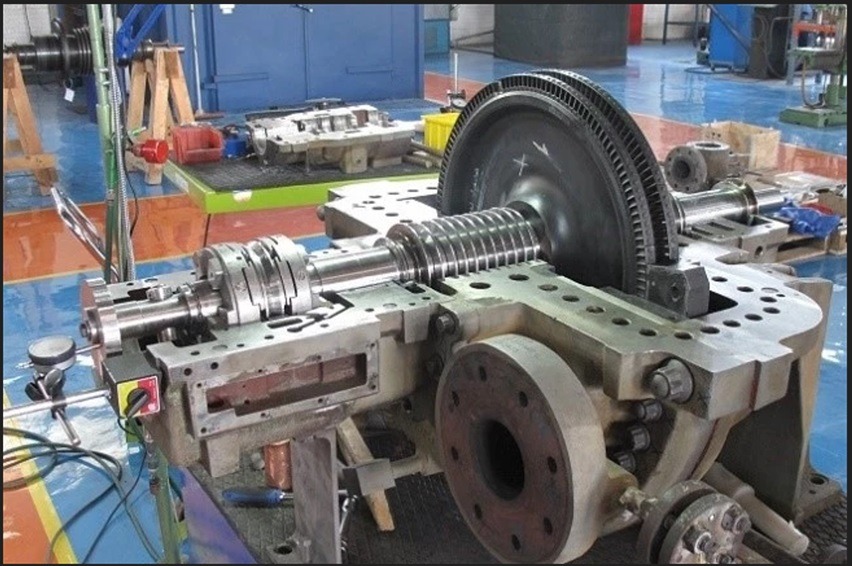
A steam turbine for a biomass power plant is a critical component in the conversion of thermal energy generated from biomass combustion or gasification into mechanical energy and subsequently into electricity, forming a central part of biomass-based combined heat and power (CHP) systems and utility-scale renewable energy plants. The process begins with the generation of high-pressure, high-temperature steam in a biomass boiler or furnace system, where carefully preprocessed biomass feedstocks—such as wood chips, sawdust, agricultural residues, municipal green waste, or industrial organic by-products—are combusted or gasified. The quality of the steam, including its pressure, temperature, and dryness fraction, is essential for efficient turbine operation, as variations can directly impact energy conversion efficiency, mechanical stability, and the longevity of turbine components. Preprocessing of the biomass feedstock ensures uniformity in size, moisture content, and calorific value, which contributes to stable combustion and consistent steam production, ultimately enabling reliable turbine operation and electricity generation.
Once high-pressure steam is generated, it is directed into the steam turbine, which is composed of several key components including the rotor, blades (both moving and stationary), casing, bearings, shaft seals, diaphragms, and governors, all precisely engineered to efficiently extract mechanical energy from the steam flow. The high-energy steam enters the turbine through stationary nozzles that convert thermal and pressure energy into kinetic energy, directing the steam onto the turbine blades. The blades, arranged in multiple stages along the rotor, are shaped to capture the steam’s kinetic energy and induce rotation of the rotor. Biomass turbines are often designed to accommodate variable steam conditions, including fluctuations in temperature, pressure, and moisture content, because biomass feedstocks can introduce variability in the steam generation process. Advanced designs may use reheat cycles or multiple pressure stages (high-pressure, intermediate-pressure, and low-pressure sections) to optimize energy extraction, improve efficiency, and reduce moisture content in the exhaust steam, which is critical for preventing blade erosion and prolonging turbine life.
The mechanical rotation of the turbine rotor is transmitted via a shaft to a generator, producing electricity for local industrial use, district heating networks, or grid supply. Biomass steam turbines are often integrated into CHP configurations, where the low-pressure exhaust steam exiting the turbine is further utilized for industrial heating processes, district heating, or other thermal applications, maximizing overall plant efficiency and energy utilization. High-efficiency turbines include designs with moisture separation stages, reheating of steam, and optimized blade geometries to increase energy extraction, reduce condensation losses, and improve overall thermodynamic performance. The casing and internal structures of the turbine are designed to withstand high-pressure and high-temperature steam while minimizing leakage and mechanical stress, with careful attention to thermal expansion, vibration, and material fatigue under continuous operation.
Operational control and monitoring are critical for biomass steam turbines due to the variable nature of biomass feedstocks and steam generation conditions. Digital control systems continuously monitor inlet steam pressure and temperature, rotor speed, vibration levels, bearing conditions, and generator output, allowing real-time adjustments to optimize turbine efficiency, maintain safe operation, and prevent mechanical failure. Governors and overspeed trip mechanisms provide additional layers of safety by regulating rotor speed and automatically shutting down the turbine in the event of abnormal conditions, ensuring plant safety and equipment protection. Steam turbines for biomass applications are designed to be resilient to fluctuations in steam quality, incorporating moisture separators, reheaters, and corrosion-resistant materials to mitigate the effects of particulates, acidic compounds, or impurities present in biomass-derived steam.
Residue and by-product considerations also influence turbine operation. Impurities, particulate matter, or chemical residues present in the flue gas and steam can cause erosion, corrosion, or fouling of turbine blades, nozzles, and heat exchange surfaces. Modern biomass plants therefore incorporate flue gas cleaning, steam treatment, and filtration systems to ensure that the steam supplied to the turbine meets stringent purity and dryness specifications. Proper water treatment, including deaeration and chemical conditioning, is used to prevent scaling, corrosion, and deposition within the boiler and turbine systems. Maintenance strategies for biomass steam turbines focus on blade inspection, rotor balancing, bearing lubrication, and monitoring of thermal and mechanical stresses to ensure reliable long-term operation and optimal performance under continuous or variable-load conditions.
Integration of the steam turbine into a biomass power plant allows the facility to achieve high overall efficiency by combining electricity generation with thermal energy utilization, creating a flexible and sustainable energy solution. Low-pressure exhaust steam can be recovered for industrial processes, district heating, greenhouse heating, or other thermal applications, while high-pressure sections of the turbine deliver maximum electricity output. Biomass steam turbines are often part of modular or hybrid energy plants, capable of processing a range of feedstocks with different moisture contents and calorific values, providing scalable and adaptable renewable energy solutions. By converting biomass thermal energy into mechanical and electrical energy, steam turbines enable renewable, low-carbon power generation while supporting circular economy practices, waste-to-energy utilization, and decarbonization of industrial and municipal energy systems.
Modern advancements in biomass steam turbine design include optimized blade geometries, corrosion- and erosion-resistant alloys, reheat and regenerative cycles, moisture separation systems, and integration with advanced control platforms. These improvements increase thermal efficiency, extend operational life, reduce maintenance requirements, and enable turbines to operate effectively under the variable steam conditions typical of biomass feedstocks. When combined with digital monitoring, predictive maintenance, and automated control systems, biomass steam turbines provide reliable, continuous power generation and heat recovery, forming the backbone of sustainable, high-efficiency biomass energy plants.
The careful coordination of biomass feedstock handling, combustion or gasification, steam generation, turbine design, and integrated thermal utilization ensures that biomass steam turbines achieve maximum energy recovery, stable electricity production, and optimal thermal performance while minimizing emissions, mechanical wear, and environmental impact. By harnessing the energy potential of biomass feedstocks through advanced steam turbine technology, biomass power plants contribute to low-carbon energy strategies, provide resilient energy supply, and promote efficient, environmentally responsible utilization of renewable resources.
A steam turbine in a biomass power plant serves as a highly efficient and central mechanism for converting the thermal energy generated from biomass combustion or gasification into mechanical energy, which is then transformed into electricity, making it a key component in renewable energy generation and combined heat and power (CHP) systems. The process begins with the controlled combustion of biomass feedstocks in a boiler or furnace system, where carefully preprocessed materials such as wood chips, sawdust, agricultural residues, municipal green waste, or industrial organic by-products are converted into high-pressure, high-temperature steam. The quality of the steam, including pressure, temperature, and dryness fraction, is critical for turbine efficiency, mechanical integrity, and long-term operational reliability. Biomass feedstocks naturally vary in moisture content, particle size, calorific value, and ash composition, which can impact the consistency of steam generation; therefore, preprocessing equipment such as shredders, grinders, trommels, and dryers is employed to ensure uniformity in feedstock characteristics, resulting in steady steam production and smooth turbine operation.
Once generated, high-pressure steam is directed into the steam turbine, which is designed with multiple stages, including high-pressure, intermediate-pressure, and low-pressure sections, to maximize energy extraction and overall efficiency. The steam first passes through stationary nozzles that convert the thermal and pressure energy into kinetic energy, directing high-velocity steam onto the turbine blades attached to the rotor. The blades are carefully designed to efficiently capture the steam’s energy and induce rotation of the rotor, which is connected to a generator to produce electricity. Biomass turbines must often accommodate variations in steam conditions caused by differences in feedstock composition, moisture content, and combustion fluctuations, and therefore may incorporate reheat cycles, moisture separation systems, and optimized blade geometries to maintain efficiency, reduce condensation losses, and prevent erosion of turbine components. The turbine casing, diaphragms, and support structures are engineered to withstand high pressures and temperatures while minimizing leakage and mechanical stress, accounting for thermal expansion, vibration, and fatigue under continuous operation.
The mechanical energy produced by the rotating turbine is transmitted through a shaft to an electrical generator, producing power for industrial use, district heating networks, or grid supply. In CHP configurations, low-pressure exhaust steam leaving the turbine can be recovered for thermal applications, such as heating industrial processes, supplying district heating systems, or greenhouse applications, thereby improving overall plant efficiency and energy utilization. Heat recovery and energy optimization are critical, as biomass steam often contains variable moisture and particulate levels; therefore, moisture separators, reheaters, and corrosion-resistant materials are incorporated to protect turbine blades, ensure long-term operation, and maintain consistent energy output. The careful design and integration of these systems allow biomass power plants to maintain high thermodynamic efficiency, reduce energy losses, and optimize both electricity and heat production.
Operational control and monitoring are central to the performance of biomass steam turbines. Advanced digital control systems continuously measure parameters such as inlet steam pressure and temperature, rotor speed, vibration, bearing condition, and generator output to ensure safe operation and maximize efficiency. Governors and overspeed protection mechanisms regulate turbine speed and provide automatic shutdown in the event of abnormal conditions, protecting the turbine from mechanical damage and ensuring plant safety. Steam purity is also a major concern in biomass applications, as impurities, particulates, or acidic compounds from combustion can cause corrosion, erosion, or fouling of turbine blades and internal surfaces. To mitigate these risks, biomass plants employ extensive flue gas cleaning, steam filtration, and water treatment systems, including deaeration and chemical conditioning, which prevent scaling, corrosion, and deposition within the boiler and turbine, thereby extending operational life and reducing maintenance requirements.
Residue management is another important factor in turbine operation. Combustion and gasification produce bottom ash, fly ash, and sometimes char or other residues, which, if not properly managed, can impact boiler and turbine performance. Modern biomass power plants incorporate automated collection and handling systems, including silos, hoppers, and conveyors, to remove residues efficiently, preventing operational interruptions and facilitating the safe disposal or repurposing of by-products. By-products such as bottom ash can be used in construction or as soil amendments, while char may serve as a secondary fuel or agricultural enhancer, supporting circular economy principles and minimizing environmental impact.
Integration of the steam turbine into a biomass power plant enhances overall efficiency and sustainability. The turbine allows the plant to simultaneously produce electricity and useful thermal energy, with exhaust steam redirected for industrial heating, district heating, or other thermal applications, resulting in CHP efficiencies that can significantly exceed standalone electricity generation. Modern biomass steam turbines are often designed with modular and hybrid capabilities to handle a variety of feedstocks with different moisture contents, particle sizes, and calorific values, providing flexibility, scalability, and resilience in renewable energy generation. By converting biomass thermal energy into mechanical and electrical energy with high efficiency, steam turbines reduce reliance on fossil fuels, lower greenhouse gas emissions, and provide consistent and reliable renewable energy solutions for industrial, municipal, and agricultural sectors.
Advances in turbine design have further enhanced the performance and reliability of biomass power plants. Optimized blade geometries, corrosion- and erosion-resistant alloys, reheat cycles, regenerative heating, moisture separation systems, and integration with digital monitoring and predictive maintenance platforms have collectively improved thermal efficiency, reduced maintenance demands, and extended the operational lifespan of turbines. These advancements enable turbines to operate effectively under variable steam conditions inherent to biomass feedstocks, ensuring continuous and stable energy output. The coordinated management of biomass feedstock preparation, steam generation, turbine operation, thermal energy recovery, emissions control, and residue handling ensures that biomass steam turbines achieve maximum energy conversion, reliable electricity production, and optimized thermal performance while minimizing environmental and mechanical risks.
By harnessing the energy potential of biomass through advanced steam turbine technology, biomass power plants contribute significantly to low-carbon energy strategies, support circular resource management, and strengthen renewable energy infrastructure. The turbine forms the backbone of modern biomass energy generation, enabling the conversion of organic waste streams into clean, sustainable electricity and heat, while providing operational flexibility, high efficiency, and environmental benefits. Integration with CHP systems, advanced digital controls, and hybrid energy plant designs ensures that biomass steam turbines not only deliver power but also maximize the utilization of thermal energy, optimize resource efficiency, and contribute to long-term sustainability and energy security.
A steam turbine in a biomass power plant is an essential component that enables the efficient conversion of thermal energy derived from the combustion or gasification of biomass into mechanical energy, which is subsequently transformed into electricity, forming the backbone of modern biomass-based combined heat and power (CHP) systems and utility-scale renewable energy plants. The process begins with the generation of high-pressure, high-temperature steam in a biomass boiler or furnace system, where carefully preprocessed feedstocks—ranging from wood chips, sawdust, and forestry residues to agricultural by-products, municipal green waste, and industrial organic waste—are combusted or gasified. The quality and consistency of the steam, including pressure, temperature, and dryness fraction, are critical to turbine performance because fluctuations can directly impact conversion efficiency, mechanical integrity, and operational reliability. Biomass feedstocks inherently vary in moisture content, calorific value, particle size, and ash composition, which can affect the uniformity of combustion and steam generation, making preprocessing equipment such as shredders, grinders, dryers, and trommels essential to ensure a homogeneous and steady supply of fuel. Automated feeders, metered hoppers, and conveyors maintain consistent fuel input, stabilizing steam production and providing the turbine with high-quality thermal energy for optimal operation.
High-pressure steam produced in the boiler is directed into the steam turbine, where it passes through stationary nozzles that convert pressure and thermal energy into kinetic energy, directing the high-velocity steam onto turbine blades mounted on the rotor. The blades, carefully engineered for maximum aerodynamic efficiency, extract energy from the steam, causing the rotor to rotate and drive a connected generator to produce electricity. Biomass turbines often incorporate multiple stages—including high-pressure, intermediate-pressure, and low-pressure sections—to maximize energy extraction, improve thermodynamic efficiency, and reduce moisture content in the exhaust steam, which is critical for preventing erosion of the blades and maintaining long-term operational reliability. In addition, advanced designs may include reheat cycles, moisture separation systems, and regenerative heating to further enhance efficiency, mitigate condensation losses, and maintain optimal steam quality under variable feedstock and combustion conditions. The turbine casing, diaphragms, and support structures are designed to withstand high pressures and temperatures while minimizing leakage and mechanical stress, accounting for thermal expansion, vibration, and fatigue associated with continuous operation under dynamic load conditions.
The mechanical energy generated by the rotating rotor is transmitted to an electrical generator, producing electricity for industrial facilities, municipal grids, or district heating networks. In CHP applications, low-pressure exhaust steam leaving the turbine can be redirected to industrial processes, district heating systems, or other thermal applications, enabling efficient utilization of residual heat and increasing overall plant energy efficiency. The design of biomass steam turbines must consider the variable composition of the steam, which can contain moisture, particulates, and acidic compounds originating from the feedstock, requiring moisture separation, filtration, and the use of corrosion-resistant materials to protect blades, nozzles, and heat transfer surfaces. Effective thermal management and careful control of steam quality are critical to maintaining efficiency, preventing mechanical wear, and ensuring reliable long-term operation.
Operational monitoring and control are essential to the performance and safety of biomass steam turbines. Advanced digital control systems continuously track turbine parameters such as inlet steam pressure and temperature, rotor speed, vibration, bearing condition, and generator output, enabling real-time adjustments to maintain optimal performance and prevent mechanical or thermal stress. Governors and overspeed protection mechanisms provide critical safety functions by regulating rotor speed and initiating emergency shutdowns under abnormal conditions, protecting both the turbine and associated equipment. Steam purity is closely managed through flue gas cleaning, water treatment, deaeration, and chemical conditioning to prevent scaling, corrosion, and deposition within the boiler and turbine systems, ensuring longevity and reducing maintenance requirements. Regular maintenance focuses on blade inspection, rotor balancing, bearing lubrication, and monitoring of mechanical and thermal stresses to ensure consistent performance and prevent unplanned downtime.
Residue management is also a significant factor in biomass turbine operation. Combustion and gasification produce bottom ash, fly ash, char, and other by-products, which must be efficiently removed and either safely disposed of or repurposed. Automated handling systems including hoppers, silos, conveyors, and transport vehicles streamline residue collection and management, preventing interruptions to boiler or turbine operation and supporting circular economy principles by enabling the reuse of ash or char in construction, soil amendment, or as a secondary fuel. Hybrid system configurations, combining biomass boilers, gasifiers, and turbines, further enhance energy recovery, improve fuel flexibility, and allow processing of diverse feedstocks with varying moisture content, calorific value, and particle size, ensuring consistent turbine operation and high overall energy efficiency.
Integration with digital energy management platforms, predictive analytics, and CHP networks allows biomass steam turbines to achieve optimal energy utilization, efficiency, and environmental performance. Automated control systems precisely regulate fuel feed, steam temperature, and pressure to optimize energy output and minimize emissions, while hybrid configurations enable simultaneous electricity and heat generation for multiple industrial, municipal, or agricultural applications. By converting biomass-derived thermal energy into mechanical and electrical energy, these turbines reduce reliance on fossil fuels, lower greenhouse gas emissions, and provide scalable, renewable energy solutions. The combination of high-efficiency steam generation, optimized turbine design, integrated heat recovery, emissions management, and advanced monitoring ensures that biomass power plants operate reliably, sustainably, and with maximum energy recovery, transforming low-value organic materials into high-value electricity and usable thermal energy.
Continuous technological advancements in blade design, material selection, corrosion and erosion resistance, reheat and regenerative cycles, moisture separation, and hybrid integration have steadily improved the efficiency, reliability, and operational lifespan of biomass steam turbines. When coupled with digital monitoring, predictive maintenance, and automated control systems, turbines can operate effectively under the variable conditions associated with biomass feedstocks while delivering stable electricity and heat output. The coordinated integration of feedstock handling, steam generation, turbine operation, thermal energy recovery, emissions mitigation, and residue management ensures maximum efficiency, operational reliability, and environmental compliance. By harnessing the energy potential of biomass through advanced steam turbine technology, biomass power plants provide low-carbon electricity and thermal energy, supporting renewable energy strategies, sustainable waste management, circular resource utilization, and resilient energy infrastructure.
A steam turbine in a biomass power plant operates as the central conversion device that transforms thermal energy generated from the controlled combustion or gasification of biomass feedstocks into mechanical energy, which is then converted into electricity through a coupled generator, forming the backbone of modern renewable energy systems and combined heat and power (CHP) plants. The process begins in the biomass boiler or furnace system, where preprocessed feedstocks—ranging from wood chips, sawdust, bark, agricultural residues, municipal green waste, and selected industrial organic by-products—are combusted or gasified to produce high-pressure, high-temperature steam. The quality of the steam, including its pressure, temperature, and dryness fraction, is critical for turbine efficiency and mechanical integrity, as fluctuations caused by variability in feedstock characteristics such as moisture content, particle size, calorific value, and ash composition can directly affect the stability of steam generation and turbine performance. To maintain uniform and consistent steam supply, preprocessing equipment such as shredders, grinders, dryers, and trommels is employed to standardize feedstock properties, while automated metered conveyors, hoppers, and feeders ensure steady delivery of biomass to the furnace, stabilizing thermal input and supporting smooth turbine operation.
The high-pressure steam enters the steam turbine and passes through stationary nozzles that convert the thermal and pressure energy of the steam into kinetic energy, directing it onto multiple stages of rotating turbine blades attached to the rotor. The blades are precisely engineered to extract maximum energy from the steam, inducing rotor rotation that drives an electrical generator. Biomass steam turbines frequently employ multi-stage configurations including high-pressure, intermediate-pressure, and low-pressure sections to optimize energy extraction, improve thermodynamic efficiency, and reduce moisture content in the exhaust steam, which is crucial for preventing erosion and prolonging the life of turbine blades. Advanced designs incorporate reheat cycles, regenerative heating, and moisture separation systems to enhance efficiency and ensure consistent energy conversion even under variable feedstock conditions, while the turbine casing, diaphragms, and internal structures are designed to withstand high-pressure and high-temperature operation, minimize leakage, and manage thermal expansion, vibration, and mechanical stresses over continuous operation.
The mechanical energy produced by the turbine rotor is transmitted to a generator to produce electricity, supplying power for industrial facilities, district heating networks, or the electrical grid. In CHP configurations, low-pressure exhaust steam is captured and utilized for industrial heating, greenhouse applications, or district heating systems, maximizing overall plant efficiency by making full use of the thermal energy produced. Because biomass-derived steam often contains moisture, particulates, and trace acidic compounds, turbine systems include moisture separators, filtration devices, and corrosion-resistant materials to protect blades, nozzles, and internal surfaces. Effective thermal management and precise control of steam quality are essential for maintaining turbine efficiency, minimizing mechanical wear, and ensuring reliable long-term operation. Advanced heat recovery systems, including economizers, superheaters, and reheaters, optimize energy extraction from the steam while stabilizing temperature and pressure profiles across turbine stages.
Operational control and monitoring are fundamental for the performance, safety, and longevity of biomass steam turbines. Digital control systems continuously measure critical parameters such as inlet steam pressure and temperature, rotor speed, bearing conditions, vibration, and generator output, enabling real-time adjustments to maintain optimal performance and prevent mechanical or thermal stress. Governors and overspeed protection systems regulate rotor speed and provide emergency shutdown capabilities in case of abnormal conditions, ensuring the turbine and associated equipment are protected. Steam quality management, including water treatment, chemical conditioning, and deaeration, prevents scaling, corrosion, and deposition within the boiler and turbine system, safeguarding efficiency and extending operational life. Maintenance activities focus on inspection of blades, balancing of rotors, lubrication of bearings, and monitoring of mechanical and thermal stresses, reducing the likelihood of unplanned downtime and ensuring continuous and reliable energy production.
Residue and by-product management is another critical aspect of turbine operation. Combustion and gasification of biomass produce bottom ash, fly ash, char, and other residues, which must be efficiently collected, removed, and either safely disposed of or repurposed. Automated handling systems, including conveyors, hoppers, and silos, facilitate continuous removal of residues, prevent operational interruptions, and support circular economy initiatives by enabling reuse of by-products, such as ash for construction materials or soil amendment, and char as a secondary fuel or agricultural enhancer. Integration with hybrid system configurations, including gasifiers and additional heat recovery units, further increases energy recovery, allows greater fuel flexibility, and ensures stable turbine operation across a range of biomass feedstock types with varying moisture content, calorific values, and particle sizes.
Modern biomass steam turbines are increasingly integrated with digital energy management platforms, predictive analytics, and hybrid CHP systems to maximize efficiency, reliability, and sustainability. Automated control systems regulate fuel feed, steam generation, and turbine operation to optimize energy output and minimize emissions, while hybrid plant designs enable simultaneous production of electricity and useful thermal energy for industrial or municipal applications. By converting the thermal energy of biomass into mechanical and electrical energy, steam turbines reduce reliance on fossil fuels, lower greenhouse gas emissions, and provide scalable, renewable energy solutions suitable for diverse applications. The combination of high-efficiency steam generation, advanced turbine design, heat recovery, emissions mitigation, and digital control ensures that biomass power plants operate reliably, sustainably, and with optimal energy utilization, transforming organic waste into electricity and thermal energy for industrial, municipal, and agricultural purposes.
Continuous advances in turbine blade design, corrosion and erosion-resistant materials, moisture separation, regenerative heating, reheat cycles, hybrid integration, and digital monitoring have steadily improved the efficiency, reliability, and operational lifespan of biomass steam turbines. By integrating precise feedstock handling, consistent steam generation, optimized turbine operation, heat recovery, emissions control, and residue management, biomass turbines achieve maximum energy conversion, stable electricity production, and effective thermal utilization while minimizing environmental and mechanical impacts. By harnessing the energy potential of biomass, steam turbines in biomass power plants play a vital role in low-carbon energy strategies, support circular resource management, enable sustainable waste-to-energy applications, and contribute to resilient, renewable energy infrastructure capable of delivering electricity and heat efficiently and reliably across multiple sectors.
Steam Boiler for Biomass Power Plant
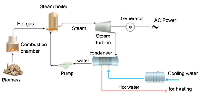
A steam boiler for a biomass power plant is a critical component that transforms the chemical energy stored in biomass feedstocks into high-pressure, high-temperature steam, which is subsequently used to drive steam turbines for electricity generation or to provide heat in combined heat and power (CHP) applications. Biomass boilers are specifically engineered to handle a wide variety of feedstocks, including wood chips, sawdust, bark, agricultural residues such as straw and corn stalks, municipal green waste, and certain industrial organic by-products. Each feedstock possesses unique characteristics such as moisture content, particle size, calorific value, density, and ash composition, which directly influence combustion behavior, heat release, and steam quality. To ensure efficient operation, biomass is often preprocessed through shredding, grinding, drying, or screening to create a uniform fuel that can be fed consistently into the boiler, maintaining stable combustion conditions and consistent steam generation.
Biomass boilers operate on different combustion principles, such as fixed-bed, moving-grate, fluidized-bed, or suspension-fired systems, each designed to optimize the thermal conversion of biomass according to the feedstock type, moisture content, and desired steam output. Fixed-bed and moving-grate boilers allow biomass to combust gradually on a stationary or moving grate, ensuring complete fuel burnout and uniform heat release. Fluidized-bed boilers provide superior mixing of fuel and air, enabling combustion of heterogeneous or high-moisture biomass with uniform temperature distribution, improved thermal efficiency, and reduced emissions. Suspension-fired boilers, though less common for bulky biomass, allow finely ground fuel to be burned in suspension with preheated air, achieving rapid heat release suitable for specific industrial processes or smaller-scale power generation. Advanced biomass boiler designs incorporate staged air injection, flue gas recirculation, and precise temperature control to optimize combustion efficiency, minimize unburned carbon, and control emissions of particulates, carbon monoxide, nitrogen oxides, and volatile organic compounds.
The thermal energy generated in the combustion zone is transferred to water or steam in boiler tubes, producing high-pressure, high-temperature steam suitable for driving turbines or supplying industrial heating processes. Heat transfer in biomass boilers is achieved through a combination of convective, conductive, and radiative mechanisms, and boiler designs often feature economizers, superheaters, and reheaters to maximize energy extraction, increase steam temperature, and improve overall thermodynamic efficiency. Economizers preheat feedwater using flue gas energy, superheaters raise steam temperature above saturation to improve turbine efficiency, and reheaters allow partially expanded steam from the turbine to be reheated and returned to subsequent turbine stages, enhancing energy extraction and reducing moisture content in the exhaust steam. The choice of heat transfer surfaces, materials, and tube arrangement is critical to withstand high-temperature flue gases, resist corrosion, and minimize fouling and ash deposition that could reduce heat transfer efficiency.
Operational efficiency and safety are key considerations in biomass boiler design. Digital control systems continuously monitor critical parameters such as fuel feed rate, combustion air supply, furnace temperature, steam pressure, steam temperature, flue gas composition, and water levels. Real-time adjustments optimize combustion, steam generation, and heat transfer while minimizing emissions and preventing unsafe operating conditions. Safety systems are integrated to address risks such as overpressure, water level deviations, fuel blockages, slagging, and ash accumulation. Automatic shutdown procedures, alarms, and redundant control mechanisms protect the boiler, steam turbine, and downstream equipment, ensuring safe and reliable operation under varying load conditions and feedstock quality.
Residue and ash management is another essential aspect of biomass boiler operation. Combustion produces bottom ash, fly ash, and sometimes char, which must be collected, removed, and either safely disposed of or repurposed. Automated ash handling systems, including hoppers, conveyors, silos, and pneumatic transport mechanisms, ensure continuous operation and prevent blockages or interruptions. Ash and char can often be recycled for construction materials, soil amendment, or as a secondary fuel, supporting circular economy principles and reducing environmental impact. Advanced biomass power plants integrate hybrid systems combining boilers with gasifiers, CHP units, and heat recovery systems to maximize energy utilization, accommodate feedstocks with varying moisture content and calorific value, and ensure consistent steam generation for turbine operation or process heat applications.
Integration with digital energy management platforms and predictive analytics further enhances biomass boiler efficiency and sustainability. Automated controls regulate fuel feed, combustion air, water and steam flow, and flue gas recirculation to optimize thermal output, minimize emissions, and maintain stable steam quality. Hybrid configurations enable simultaneous production of electricity and useful thermal energy, achieving high overall plant efficiency. Water treatment systems, including deaeration, chemical dosing, and filtration, ensure high-quality steam to protect turbine blades, prevent scaling and corrosion, and maintain long-term boiler and turbine reliability. The combination of high-efficiency combustion, effective heat transfer, advanced control systems, emissions mitigation, and residue management ensures that biomass boilers convert a wide range of feedstocks into high-pressure, high-temperature steam efficiently, safely, and sustainably, forming the foundation for renewable energy generation in biomass power plants.
Modern biomass boilers continue to evolve with advancements in materials, combustion technologies, heat recovery, and control systems, improving thermal efficiency, reliability, and environmental performance. Optimized burner and grate designs, corrosion- and erosion-resistant alloys, enhanced ash handling systems, and integration with digital monitoring platforms enable boilers to operate effectively under the variable conditions inherent to biomass feedstocks. By converting low-value biomass materials into high-pressure steam, biomass boilers provide a renewable, low-carbon energy source that supports electricity generation, CHP applications, industrial process heat, and district heating, while promoting circular resource management and reducing greenhouse gas emissions. Their ability to handle heterogeneous feedstocks, integrate with turbines and heat recovery systems, and deliver consistent thermal energy makes biomass boilers a cornerstone of sustainable energy infrastructure, enabling efficient, environmentally responsible, and economically viable renewable energy solutions.
A biomass steam boiler for a power plant represents the cornerstone of energy conversion within the facility, transforming the chemical energy stored in a wide variety of biomass feedstocks into high-pressure, high-temperature steam that can drive steam turbines for electricity generation and simultaneously provide process or district heating in combined heat and power (CHP) applications. The operational efficiency and reliability of a biomass boiler are closely tied to the careful selection, preparation, and handling of feedstocks, which can include wood chips, sawdust, bark, forestry residues, agricultural by-products such as straw, husks, and corn stalks, municipal green waste, and certain organic industrial residues. Each type of biomass has unique characteristics including calorific value, moisture content, particle size, density, and ash composition, all of which influence combustion behavior, heat release rates, and the quality of the steam generated. To ensure uniformity and stable operation, preprocessing equipment such as shredders, grinders, trommels, and dryers is employed to produce a consistent feedstock that can be delivered steadily into the boiler via automated feeders, hoppers, and metered conveyors, stabilizing the combustion process and maintaining a reliable thermal input to the boiler.
Biomass boilers operate on several combustion principles that are specifically adapted to the feedstock characteristics and the desired steam output. Fixed-bed and moving-grate boilers are designed for gradual, controlled combustion of solid biomass, ensuring complete fuel burnout and uniform heat release. In these systems, biomass moves slowly across a grate or remains on a stationary bed while air is supplied in stages to optimize combustion efficiency and reduce emissions. Fluidized-bed boilers utilize a bed of sand or other inert materials that is fluidized by the upward flow of air, creating intense mixing that allows for uniform combustion of heterogeneous or high-moisture biomass and excellent temperature control. This technology enables higher thermal efficiency, lower pollutant formation, and improved handling of feedstocks with variable size and composition. Suspension-fired biomass boilers, less common for large-scale bulky biomass but useful for finely milled fuels, combust the fuel in suspension with preheated air, enabling rapid heat release and precise temperature management. Across all these designs, advanced features such as staged air injection, flue gas recirculation, and precise temperature regulation are incorporated to optimize combustion efficiency, maximize heat release, and reduce emissions of particulates, carbon monoxide, nitrogen oxides, and volatile organic compounds.
The heat released from combustion is absorbed in boiler tubes to generate steam, with careful attention to convective, conductive, and radiative heat transfer mechanisms that maximize energy extraction and minimize losses. Modern biomass boilers often include economizers, superheaters, and reheaters to improve thermodynamic performance. Economizers capture residual heat from flue gases to preheat the incoming feedwater, increasing boiler efficiency and reducing fuel consumption. Superheaters raise the temperature of saturated steam above its boiling point, producing superheated steam that enhances turbine efficiency and reduces condensation in the blades. Reheaters allow partially expanded steam from intermediate turbine stages to be reheated and returned to subsequent turbine stages, enabling more energy to be extracted while controlling moisture levels in the exhaust steam. The choice of materials and tube configurations is critical, as flue gases from biomass combustion can be highly corrosive and laden with particulate matter, potentially leading to fouling, erosion, and heat transfer degradation if not properly managed. Corrosion-resistant alloys, optimized tube arrangements, and regular maintenance schedules are essential to maintain performance and prolong operational life.
Operational monitoring and control are integral to biomass boiler performance, safety, and efficiency. Advanced digital control systems track critical parameters such as fuel feed rates, combustion air supply, furnace temperature, steam pressure, steam temperature, water levels, and flue gas composition, enabling real-time optimization of combustion and steam generation. Safety mechanisms are designed to protect the boiler and connected systems from overpressure, water level fluctuations, slagging, ash accumulation, and other operational hazards. Automated shutdown sequences, alarms, and redundancy in control systems prevent accidents and protect the boiler, steam turbine, and downstream equipment. Proper water treatment, including deaeration, chemical dosing, and filtration, ensures high-quality steam, prevents scaling, and mitigates corrosion, safeguarding both the boiler and turbine for long-term operation.
Residue and by-product management is an essential consideration in biomass boiler operation. Combustion generates bottom ash, fly ash, char, and occasionally other residues depending on feedstock composition and combustion method. Efficient ash handling systems including silos, hoppers, conveyors, and pneumatic transport mechanisms remove these by-products continuously, preventing blockages, maintaining uninterrupted operation, and allowing for the safe disposal or repurposing of residues. Many biomass power plants incorporate circular economy practices, reusing ash in construction materials, soil amendment, or as secondary fuel, while char can be repurposed as a renewable energy source or agricultural enhancer. Hybrid plant designs, integrating gasifiers, additional boilers, or CHP systems, further improve energy recovery, allow flexible operation with different feedstocks, and ensure consistent steam generation for turbines and thermal applications.
Biomass steam boilers are increasingly integrated with digital energy management systems, predictive analytics, and advanced CHP configurations to maximize plant efficiency and sustainability. Automated control systems regulate fuel feed, combustion air, water and steam flow, and flue gas recirculation, optimizing thermal output while minimizing emissions. The combination of high-efficiency combustion, heat recovery, residue management, emissions control, and precise monitoring ensures that biomass boilers convert diverse feedstocks into high-pressure, high-temperature steam efficiently and reliably. Modern advancements in materials, combustion technologies, ash handling, and heat recovery continue to improve boiler efficiency, reduce maintenance requirements, and extend operational lifespan, enabling plants to produce renewable energy at scale while supporting sustainable waste management practices and reducing greenhouse gas emissions. By harnessing the energy potential of biomass, steam boilers provide a critical foundation for low-carbon electricity and heat generation, forming the core of environmentally responsible, economically viable, and technologically advanced biomass power plants that deliver continuous and sustainable energy solutions across industrial, municipal, and agricultural sectors.
A biomass steam boiler in a power plant functions as the central energy conversion unit, transforming the chemical energy of various biomass feedstocks into high-pressure, high-temperature steam that drives turbines for electricity generation or provides thermal energy for industrial processes and district heating in combined heat and power (CHP) configurations. The feedstocks used in biomass boilers are highly diverse, ranging from wood chips, sawdust, bark, and forestry residues to agricultural by-products such as straw, husks, corn stalks, municipal green waste, and organic industrial residues. Each type of feedstock exhibits distinct characteristics including moisture content, calorific value, particle size, density, and ash composition, all of which directly influence combustion efficiency, heat release, and steam quality. Preprocessing equipment such as shredders, grinders, trommels, and dryers is used to create a uniform fuel size and consistency, while automated feeding systems, hoppers, and conveyors ensure a continuous and controlled delivery of fuel into the boiler, maintaining steady combustion, stable thermal input, and consistent steam generation necessary for efficient turbine operation and heat supply.
Biomass boilers utilize several combustion technologies specifically tailored to handle the heterogeneous nature of feedstocks and achieve optimal steam production. Fixed-bed and moving-grate boilers allow solid biomass to combust gradually on a stationary or mechanically moving grate, ensuring complete burnout and uniform heat release while minimizing unburned carbon and particulate emissions. Fluidized-bed boilers employ a bed of sand or other inert material fluidized by upward airflow, creating intense turbulence that ensures uniform combustion, excellent temperature control, and higher thermal efficiency, especially for feedstocks with high moisture content or variable particle sizes. Suspension-fired or pulverized fuel boilers, though less common for bulky biomass, enable finely ground biomass particles to be burned in suspension with preheated air, allowing rapid heat release and precise temperature control. Advanced boiler designs integrate staged air injection, flue gas recirculation, and precise temperature control to maximize combustion efficiency, reduce nitrogen oxide and carbon monoxide formation, and maintain stable and clean combustion even under variable feedstock conditions.
The thermal energy released during biomass combustion is absorbed in boiler tubes to generate steam, with heat transfer achieved through convection, conduction, and radiation. Modern biomass boilers are equipped with economizers, superheaters, and reheaters to maximize energy recovery and improve overall plant efficiency. Economizers preheat the incoming feedwater using residual flue gas heat, reducing fuel consumption and increasing thermal efficiency. Superheaters raise the temperature of saturated steam to produce superheated steam, enhancing the efficiency of downstream turbines and reducing condensation losses in the blades. Reheaters are used to reheat partially expanded steam from intermediate-pressure turbine stages, allowing more energy extraction and reducing moisture content in the low-pressure stages. Material selection for boiler tubes, furnace walls, and heat transfer surfaces is critical, as flue gases from biomass combustion can be highly corrosive and laden with particulates, potentially causing erosion, fouling, and efficiency losses if not properly addressed through corrosion-resistant alloys, optimized tube arrangements, and regular maintenance.
Operational monitoring and control play a central role in the safe and efficient operation of biomass boilers. Digital control systems continuously monitor key parameters including fuel feed rate, combustion air supply, furnace temperature, steam pressure, steam temperature, water levels, and flue gas composition, allowing real-time optimization of combustion and heat transfer processes. Safety systems manage risks associated with overpressure, water level deviations, ash accumulation, and slagging, while automated shutdown sequences, alarms, and redundancies ensure safe operation under variable feedstock quality and load conditions. High-quality water treatment, including deaeration, chemical dosing, and filtration, is essential to prevent scaling, corrosion, and deposition within the boiler and connected steam turbines, ensuring long-term reliability and efficient energy conversion.
Residue and by-product handling is another vital component of biomass boiler operation. Combustion produces bottom ash, fly ash, char, and other residues depending on feedstock type and combustion technology. Efficient ash handling systems, including silos, hoppers, conveyors, and pneumatic transport, allow continuous removal of residues, prevent operational interruptions, and facilitate safe disposal or reuse. Many biomass power plants implement circular economy practices by repurposing ash in construction materials, soil amendment, or as a secondary fuel, while char can be used for energy recovery or agricultural enhancement. Hybrid plant designs integrate boilers with gasifiers, steam turbines, CHP units, and heat recovery systems, improving overall energy efficiency, enabling feedstock flexibility, and maintaining stable steam supply for turbine operation or thermal applications, even when feedstock properties vary significantly.
Integration with digital energy management platforms, predictive analytics, and CHP networks allows biomass boilers to operate at peak efficiency and environmental compliance. Automated controls regulate fuel feeding, combustion air, water and steam flow, and flue gas recirculation, optimizing thermal output, reducing emissions, and maintaining consistent steam quality. Modern biomass boilers are designed to handle a wide range of feedstocks with varying moisture content and calorific value, ensuring flexible and reliable operation. Advances in materials, combustion technologies, heat recovery systems, ash handling, and control mechanisms have steadily improved thermal efficiency, operational reliability, and environmental performance. By efficiently converting diverse biomass materials into high-pressure, high-temperature steam, biomass boilers provide a renewable, low-carbon energy source for electricity generation, industrial heat, and district heating, while promoting sustainable waste management, circular resource utilization, and greenhouse gas emission reduction. Their ability to integrate seamlessly with steam turbines, CHP systems, and hybrid energy configurations makes biomass boilers a core technology in modern renewable energy infrastructure, delivering continuous, reliable, and environmentally responsible energy solutions across industrial, municipal, and agricultural sectors.
A biomass steam boiler in a power plant serves as the central unit for converting the chemical energy stored in organic feedstocks into high-pressure, high-temperature steam, which is then used to drive turbines for electricity generation or provide process heat and district heating in combined heat and power (CHP) systems. These boilers are specifically designed to accommodate a wide variety of biomass materials, including wood chips, sawdust, bark, forestry residues, agricultural by-products such as straw, husks, and corn stalks, as well as municipal green waste and certain organic industrial residues. Each feedstock presents unique challenges due to variations in calorific value, moisture content, particle size, density, and ash composition, all of which can affect combustion efficiency, heat release, and the quality of the generated steam. To address these variations, feedstocks are commonly preprocessed through shredding, grinding, drying, and screening to achieve uniform particle size and moisture content. Automated feeding systems, including hoppers, conveyors, and metered feeders, maintain a continuous and controlled fuel supply to the boiler, ensuring stable combustion, consistent steam production, and optimal thermal input for turbines or thermal applications.
The combustion technology employed in biomass boilers is adapted to the characteristics of the feedstock and the required steam output. Fixed-bed and moving-grate boilers allow solid biomass to combust gradually on a stationary or moving grate, ensuring complete fuel burnout, uniform heat release, and minimal unburned carbon in the ash. Fluidized-bed boilers, on the other hand, use a bed of inert particles such as sand fluidized by an upward flow of air to create uniform combustion, excellent temperature control, and efficient energy conversion, making them particularly effective for heterogeneous or high-moisture feedstocks. Suspension-fired or pulverized fuel boilers enable finely ground biomass particles to combust in suspension with preheated air, allowing for rapid heat release and precise temperature control. Advanced biomass boilers often feature staged air injection, flue gas recirculation, and temperature management systems to optimize combustion efficiency, minimize the formation of nitrogen oxides, carbon monoxide, and volatile organic compounds, and maintain stable operation even under variable fuel conditions.
The heat released from biomass combustion is absorbed in boiler tubes to generate steam, with heat transfer occurring through convection, conduction, and radiation. Modern biomass boilers employ economizers, superheaters, and reheaters to maximize thermal efficiency and energy extraction. Economizers utilize residual flue gas heat to preheat incoming feedwater, reducing fuel consumption and improving overall plant efficiency. Superheaters raise saturated steam to superheated conditions, increasing the efficiency of downstream turbines and reducing condensation losses in the blades. Reheaters allow partially expanded steam from intermediate turbine stages to be reheated and returned to subsequent stages, extracting more energy and reducing moisture content in the low-pressure sections. The materials used for boiler tubes, furnace walls, and heat transfer surfaces are carefully selected to resist the corrosive and abrasive nature of biomass flue gases, which contain particulates, alkali metals, and acidic compounds that can cause fouling, erosion, or corrosion if not properly managed. Regular maintenance, inspection, and cleaning schedules are essential to sustain heat transfer efficiency and prolong operational life.
Operational control and monitoring are critical for ensuring efficient and safe biomass boiler operation. Digital control systems continuously track fuel feed rates, combustion air supply, furnace temperature, steam pressure, steam temperature, water levels, and flue gas composition, allowing real-time adjustments to optimize combustion, heat transfer, and steam quality. Safety systems mitigate risks associated with overpressure, low or high water levels, ash accumulation, slagging, and blockages, while automated shutdown sequences, alarms, and redundancies protect the boiler, turbines, and downstream equipment. Water treatment, including deaeration, chemical dosing, and filtration, is vital to prevent scaling, corrosion, and deposition within the boiler and connected steam turbines, ensuring reliability and extending the life of plant components.
Residue and by-product management is another critical aspect of biomass boiler operation. Combustion produces bottom ash, fly ash, char, and occasionally other residues depending on feedstock composition and combustion method. Efficient ash handling systems, including silos, hoppers, conveyors, and pneumatic transport mechanisms, allow continuous removal of residues, preventing operational interruptions and enabling safe disposal or reuse. Many biomass plants adopt circular economy practices, repurposing ash in construction materials, as soil amendments, or as secondary fuel, while char can serve as a renewable energy source or agricultural enhancer. Hybrid plant designs that integrate boilers with gasifiers, steam turbines, CHP units, and heat recovery systems further improve overall energy efficiency, enabling flexible operation with varying feedstocks while maintaining a stable and consistent supply of steam for turbines or thermal applications.
Integration with digital energy management platforms, predictive analytics, and CHP systems allows biomass boilers to operate at peak efficiency and sustainability. Automated controls optimize fuel feed, combustion air, water and steam flow, and flue gas recirculation, maximizing thermal output while minimizing emissions and ensuring consistent steam quality. Modern biomass boilers are capable of processing feedstocks with wide-ranging moisture content, calorific value, and particle size, providing flexible and reliable operation. Advances in materials, combustion technology, heat recovery systems, ash handling, and digital control mechanisms have steadily improved boiler efficiency, operational reliability, and environmental performance. By converting diverse biomass feedstocks into high-pressure, high-temperature steam, biomass boilers provide a renewable, low-carbon source of energy for electricity generation, industrial processes, and district heating, while supporting sustainable waste management, circular resource utilization, and greenhouse gas reduction. Their integration with steam turbines, CHP systems, and hybrid configurations makes them a cornerstone of modern renewable energy infrastructure, delivering continuous, efficient, and environmentally responsible energy solutions for industrial, municipal, and agricultural applications.
Small Scale Biomass Power Plant
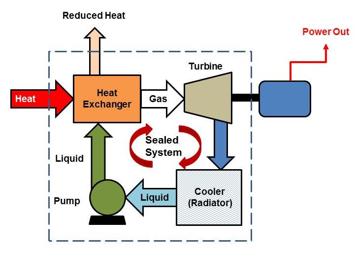
A small-scale biomass power plant is designed to convert locally available biomass feedstocks into electricity, heat, or combined heat and power (CHP) for industrial, agricultural, or community applications, providing decentralized and sustainable energy solutions that reduce dependence on fossil fuels. Unlike large utility-scale biomass facilities, small-scale plants are optimized for lower capacity ranges, typically from a few hundred kilowatts up to several megawatts, allowing communities, farms, and small industries to harness energy from wood residues, agricultural waste, energy crops, food processing by-products, or municipal organic waste. The selection and preprocessing of biomass feedstocks are critical, as the efficiency, reliability, and operational consistency of the plant depend on uniform particle size, moisture content, and calorific value. Feedstocks are often shredded, ground, dried, and screened to ensure steady combustion, and automated or semi-automated feed systems deliver the prepared fuel to the boiler or gasifier at a controlled rate, maintaining stable thermal input for steam generation or direct thermal conversion processes.
Combustion technologies in small-scale biomass power plants are adapted to feedstock characteristics, energy requirements, and local operational conditions. Moving-grate or fixed-bed boilers are common, providing gradual combustion of solid biomass with efficient energy extraction and minimal unburned residues. Fluidized-bed technology, although less frequent at small scales due to complexity, offers improved combustion uniformity and the ability to handle high-moisture or heterogeneous biomass, achieving high thermal efficiency and low emissions. In some small-scale plants, gasification is employed, where biomass is partially combusted under controlled oxygen conditions to produce a combustible gas mixture that can be burned in internal combustion engines, microturbines, or small gas turbines, offering greater flexibility in feedstock use and potential for combined heat and power generation. Suspension-fired systems may be used for finely milled biomass but are typically more suitable for specialized industrial applications due to fuel preparation requirements.
The thermal energy released in the combustion or gasification process is transferred to water or steam in small-scale boilers to produce high-pressure steam for driving small steam turbines or reciprocating engines. Heat transfer surfaces are carefully designed to optimize energy extraction, with economizers preheating feedwater using residual flue gas heat, superheaters increasing steam temperature to improve turbine efficiency, and, in some CHP configurations, low-pressure steam or hot water directed to local heating applications. Material selection and design considerations account for the corrosive and abrasive nature of biomass flue gases, particularly in small-scale plants where feedstock variability can cause greater fluctuations in combustion conditions. Corrosion-resistant alloys, optimized tube arrangements, and periodic maintenance ensure sustained performance, reliability, and longevity of the boiler and connected energy conversion equipment.
Operational control and monitoring are fundamental even in small-scale biomass plants. Digital or semi-automated control systems regulate fuel feed, combustion air supply, furnace temperature, steam pressure, and water levels to maintain efficient and safe operation. Safety measures include overpressure protection, low-water cutoffs, and temperature alarms, with manual or automated shutdown procedures in case of abnormal conditions. Water treatment, including filtration, chemical dosing, and deaeration, ensures high-quality steam for turbine or engine operation, reducing scaling, corrosion, and maintenance requirements. Small-scale plants must also manage residues such as bottom ash, fly ash, and char, which can be removed using hoppers, conveyors, or manual collection, and may be repurposed as soil amendments, secondary fuels, or construction material, supporting sustainable and circular waste management practices.
Emissions control is an important consideration in small-scale biomass power plants to meet local environmental regulations and maintain air quality. Technologies such as cyclones, bag filters, electrostatic precipitators, or scrubbers can reduce particulate matter, while staged combustion and flue gas recirculation minimize carbon monoxide, nitrogen oxides, and volatile organic compounds. Smaller plants benefit from modular designs that allow operators to integrate emission control systems proportionally to plant capacity, maintaining compliance without excessive capital or operational costs. Additionally, hybrid configurations that combine small-scale boilers or gasifiers with thermal storage, microturbines, or CHP networks improve energy efficiency, maximize the use of generated thermal energy, and provide operational flexibility, allowing the plant to respond effectively to local electricity or heating demand fluctuations.
Small-scale biomass power plants play a critical role in promoting renewable energy adoption, rural electrification, and sustainable waste management. By converting locally available biomass into electricity and heat, these plants reduce reliance on fossil fuels, lower greenhouse gas emissions, and enable communities and industries to achieve energy independence. They are particularly well-suited to areas with abundant agricultural or forestry residues, food processing waste, or municipal organic waste, where centralized energy production is either impractical or inefficient. Modern small-scale biomass plants emphasize reliability, operational simplicity, and modularity, allowing for incremental capacity increases, flexible feedstock utilization, and integration with local energy networks. Digital monitoring, predictive maintenance, and automated control systems further enhance plant performance, safety, and efficiency, making small-scale biomass power plants a viable, sustainable, and scalable solution for distributed energy generation, industrial heat supply, and community-level combined heat and power applications.
A small-scale biomass power plant functions as a compact, decentralized energy system capable of converting locally sourced biomass feedstocks into electricity, heat, or combined heat and power (CHP), providing renewable energy solutions for industrial facilities, agricultural operations, or community-scale applications. These plants are typically designed for capacities ranging from a few hundred kilowatts up to several megawatts, offering the flexibility to operate efficiently in areas where large utility-scale biomass plants would be impractical or uneconomical. Biomass feedstocks for small-scale plants include wood chips, sawdust, bark, forestry residues, energy crops, agricultural by-products such as straw and husks, municipal green waste, and selected industrial organic residues. The variability in calorific value, moisture content, particle size, density, and ash composition across these feedstocks requires careful preprocessing, including shredding, grinding, drying, and screening, to create uniform material that can be delivered consistently to the boiler or gasifier. Automated or semi-automated feeding systems, including conveyors, hoppers, and metered feeders, maintain stable fuel input, ensuring continuous combustion, consistent steam generation, or predictable gasification output, which is critical for efficient operation and optimal energy recovery.
The choice of combustion or gasification technology in small-scale biomass power plants depends on the feedstock characteristics, plant capacity, and desired energy output. Fixed-bed and moving-grate boilers are commonly used for solid biomass, allowing controlled combustion on a stationary or mechanically moving grate, ensuring thorough fuel burnout, uniform heat release, and minimal unburned carbon in ash. Fluidized-bed boilers, though more complex, provide enhanced combustion uniformity, excellent temperature control, and high thermal efficiency, particularly for heterogeneous or high-moisture feedstocks. Gasification-based small-scale plants convert biomass into a combustible gas mixture under controlled oxygen conditions, which can be burned in reciprocating engines, microturbines, or small gas turbines. Gasification enables efficient use of diverse feedstocks, flexible energy production, and the ability to integrate CHP systems effectively. Suspension-fired systems for finely milled biomass are also used in specialized small-scale applications, offering rapid combustion and precise thermal control.
Thermal energy produced from biomass combustion or gasification is transferred to water or steam in small-scale boilers to generate high-pressure, high-temperature steam for driving turbines, engines, or other energy conversion devices. Heat transfer optimization in these boilers often involves economizers, superheaters, and reheaters. Economizers preheat feedwater using residual flue gas energy, improving thermal efficiency and reducing fuel consumption. Superheaters raise saturated steam to superheated conditions, enhancing turbine or engine efficiency, reducing condensation losses, and enabling higher-quality energy output. In CHP configurations, low-pressure steam or hot water is utilized for industrial processes, greenhouse heating, or district heating systems, maximizing the overall energy efficiency of the plant. Boiler materials and tube configurations are designed to withstand the corrosive, abrasive, and particulate-laden flue gases characteristic of biomass combustion, with corrosion-resistant alloys and optimized tube arrangements mitigating wear, fouling, and heat transfer degradation. Regular inspection, maintenance, and cleaning schedules ensure sustained efficiency and reliable operation.
Operational control and monitoring are critical in small-scale biomass power plants to ensure safe, efficient, and consistent energy production. Digital or semi-automated control systems monitor key parameters, including fuel feed rates, combustion air supply, furnace temperature, steam pressure and temperature, water levels, and flue gas composition, allowing real-time optimization of combustion, gasification, and heat transfer processes. Safety mechanisms manage risks such as overpressure, low or high water levels, ash accumulation, and blockages, while automated shutdown sequences, alarms, and redundancies protect both the boiler or gasifier and the connected turbine, engine, or CHP system. Proper water treatment, including filtration, chemical dosing, and deaeration, maintains high-quality steam, prevents scaling and corrosion, and reduces maintenance requirements, ensuring long-term reliability and operational stability.
Residue and by-product management is an important aspect of small-scale biomass power plant operation. Combustion and gasification produce bottom ash, fly ash, char, and other residues, which must be efficiently collected, removed, and either safely disposed of or repurposed. Automated or semi-automated ash handling systems, including silos, hoppers, conveyors, and pneumatic transport mechanisms, enable continuous removal of residues, preventing operational interruptions and supporting circular economy practices. Ash may be reused in construction materials or as soil amendments, while char can serve as a secondary fuel or agricultural enhancer. Small-scale plants may integrate hybrid designs that combine boilers or gasifiers with heat recovery units, turbines, microturbines, engines, and CHP networks, improving overall energy efficiency, providing flexibility to accommodate feedstocks with varying moisture content and calorific value, and maintaining stable energy output for electricity or thermal applications.
Emissions control in small-scale biomass power plants is crucial to comply with environmental regulations and protect air quality. Technologies such as cyclones, bag filters, electrostatic precipitators, or wet scrubbers reduce particulate emissions, while staged combustion, flue gas recirculation, and temperature control minimize carbon monoxide, nitrogen oxide, and volatile organic compound formation. Smaller plants benefit from modular designs that allow proportional integration of emission control systems, balancing environmental compliance with economic feasibility. Additionally, hybrid configurations that combine biomass boilers or gasifiers with thermal storage, microturbines, or CHP networks enhance energy efficiency, maximize utilization of thermal energy, and allow operators to respond to fluctuations in local electricity and heating demand effectively.
Small-scale biomass power plants offer numerous advantages, including renewable energy production, decentralized energy supply, reduced greenhouse gas emissions, and sustainable waste management. They provide communities, farms, and small industries with an opportunity to achieve energy independence, utilize locally available biomass resources, and generate electricity and heat simultaneously. Modular, flexible designs allow incremental capacity expansion, adaptation to a range of feedstocks, and integration with local energy networks. Digital monitoring, predictive maintenance, and automated control systems further enhance plant performance, operational reliability, and efficiency. By converting low-value biomass into electricity, process heat, and thermal energy, small-scale biomass power plants contribute to renewable energy adoption, sustainable waste utilization, circular resource management, and resilient energy infrastructure, providing environmentally responsible and economically viable solutions for distributed energy generation, industrial applications, and community-level CHP systems.
A small-scale biomass power plant serves as an efficient and decentralized energy solution capable of converting a diverse array of locally available biomass feedstocks into electricity, heat, or combined heat and power (CHP), meeting the energy needs of farms, industrial facilities, and communities while reducing reliance on fossil fuels and supporting sustainable waste management practices. These plants, typically designed for capacities ranging from a few hundred kilowatts up to several megawatts, are optimized to handle feedstocks that include wood chips, sawdust, bark, forestry residues, energy crops, agricultural by-products such as straw, corn stalks, and husks, as well as municipal organic waste and select industrial residues. The inherent variability of these materials in terms of moisture content, particle size, calorific value, density, and ash composition requires careful preprocessing, which may involve shredding, grinding, drying, and screening to create uniform fuel suitable for controlled combustion or gasification. Automated feeding systems, including metered conveyors, hoppers, and augers, ensure steady and regulated fuel delivery to the boiler or gasifier, maintaining consistent thermal input, stabilizing combustion, and producing reliable steam or gas outputs for power generation and heat supply.
Small-scale biomass plants employ a variety of combustion and energy conversion technologies tailored to feedstock characteristics and energy output requirements. Fixed-bed and moving-grate boilers are commonly utilized for solid biomass, allowing fuel to combust gradually on stationary or moving grates, achieving thorough burnout, uniform heat release, and minimal residual carbon. Fluidized-bed boilers, though more complex, offer enhanced combustion uniformity, precise temperature control, and the ability to process high-moisture or heterogeneous biomass efficiently, delivering higher thermal efficiency and lower pollutant emissions. Gasification-based systems convert biomass under controlled oxygen conditions into a combustible gas mixture, which can then be burned in internal combustion engines, microturbines, or small-scale gas turbines, providing flexible and efficient electricity and heat production. Suspension-fired systems, suitable for finely milled biomass, allow rapid combustion and precise temperature regulation, although they are generally applied in specialized industrial contexts where feedstock uniformity can be guaranteed. Advanced small-scale systems incorporate staged air injection, flue gas recirculation, and real-time temperature and combustion monitoring to optimize fuel utilization, minimize emissions, and maintain steady energy output despite feedstock variability.
The thermal energy generated in biomass boilers or gasifiers is transferred to water or steam to produce high-pressure, high-temperature steam for driving turbines, engines, or CHP systems. Heat transfer surfaces are designed for maximum efficiency, with economizers preheating feedwater using residual flue gas heat, superheaters raising saturated steam to superheated conditions for higher turbine efficiency, and, in some CHP configurations, reheaters extending the utility of partially expanded steam. In addition to electricity generation, low-pressure steam or hot water is often distributed for industrial processes, greenhouse heating, or district heating networks, maximizing overall plant efficiency and energy utilization. Boiler design must accommodate the corrosive and abrasive characteristics of biomass flue gases, which contain particulates, alkali metals, and acidic compounds; corrosion-resistant alloys, optimized tube arrangements, and routine maintenance are essential to preserve heat transfer efficiency and extend component lifespan.
Operational control and monitoring are critical to ensure that small-scale biomass power plants function safely, efficiently, and reliably. Digital or semi-automated control systems regulate fuel feed, combustion air, furnace temperature, steam pressure and temperature, water levels, and flue gas composition, allowing continuous optimization of combustion, gasification, and heat transfer processes. Safety systems manage overpressure, low or high water levels, ash accumulation, slagging, and potential blockages, with automated shutdown sequences and alarms providing protective measures for both boilers or gasifiers and downstream turbines or engines. Water treatment is essential to maintain steam quality, prevent scaling and corrosion, and ensure long-term reliability, with filtration, deaeration, and chemical dosing applied according to plant size, feedwater composition, and operational requirements.
Residue and by-product management is a key consideration in small-scale biomass plant operation. Combustion or gasification produces bottom ash, fly ash, char, and other residues, which must be efficiently collected and either safely disposed of or repurposed. Automated or semi-automated ash handling systems, including hoppers, silos, conveyors, and pneumatic transport mechanisms, enable continuous removal of residues, maintaining uninterrupted operation and supporting sustainable practices. Ash may be reused in construction materials or as soil amendment, while char can be applied as a secondary fuel or agricultural enhancer. Many small-scale plants integrate hybrid designs combining boilers or gasifiers with heat recovery systems, microturbines, engines, or CHP networks, improving energy efficiency, enabling feedstock flexibility, and maintaining consistent energy output for both electricity and thermal applications.
Environmental and emissions control is crucial even for small-scale biomass plants to comply with local regulations and maintain air quality. Systems such as cyclones, bag filters, electrostatic precipitators, or wet scrubbers remove particulate matter, while staged combustion, flue gas recirculation, and temperature optimization reduce emissions of carbon monoxide, nitrogen oxides, and volatile organic compounds. Modular design allows proportional integration of emissions control technologies appropriate for plant size, maintaining regulatory compliance without excessive capital or operational costs. Hybrid integration with thermal storage, CHP systems, or microgrids enables efficient use of both electricity and heat, providing flexibility to meet variable local demand while enhancing overall plant efficiency.
Small-scale biomass power plants play a vital role in promoting renewable energy adoption, decentralized energy generation, rural electrification, and sustainable waste management. By converting locally available biomass into electricity and heat, they reduce reliance on fossil fuels, decrease greenhouse gas emissions, and provide reliable energy to industries, agricultural operations, and communities. Modular, flexible designs allow for incremental capacity expansion, accommodate variable feedstocks, and integrate with local energy networks, while digital monitoring, predictive maintenance, and automated control systems enhance operational reliability, efficiency, and safety. By effectively harnessing the energy potential of biomass, small-scale power plants support circular resource management, contribute to low-carbon energy strategies, and provide resilient, sustainable energy solutions that deliver continuous electricity and thermal energy for industrial, municipal, and agricultural applications.
A small-scale biomass power plant operates as a decentralized energy facility that converts locally available biomass feedstocks into electricity, heat, or combined heat and power (CHP), providing renewable energy solutions for farms, industrial facilities, communities, and district heating networks while reducing reliance on fossil fuels and promoting sustainable waste management. These plants typically range in capacity from a few hundred kilowatts up to several megawatts, allowing them to serve applications that are too small or geographically dispersed for large utility-scale biomass plants. The feedstocks used in these plants are diverse and include wood chips, sawdust, bark, forestry residues, agricultural by-products such as straw, husks, and corn stalks, energy crops, municipal green waste, and certain organic industrial residues. Each feedstock presents unique challenges due to variations in calorific value, moisture content, particle size, density, and ash composition, all of which directly influence combustion behavior, energy output, and residue characteristics. To achieve consistent performance, feedstocks are typically preprocessed through shredding, grinding, drying, screening, or pelletizing to create a uniform fuel suitable for controlled combustion or gasification. Automated feeding systems such as hoppers, augers, and metered conveyors regulate fuel input, maintaining steady thermal input to the boiler or gasifier and ensuring consistent steam, hot water, or syngas production necessary for turbines, engines, or CHP units.
The energy conversion technologies employed in small-scale biomass plants are adapted to feedstock properties and the desired energy output. Fixed-bed and moving-grate boilers are widely used for solid biomass, enabling gradual combustion on stationary or mechanically moving grates that ensures complete fuel burnout, uniform heat release, and minimal unburned carbon in ash. Fluidized-bed boilers, though more complex, provide enhanced combustion uniformity, precise temperature control, and high thermal efficiency, particularly suitable for heterogeneous or high-moisture feedstocks, while reducing emissions of particulates and nitrogen oxides. Gasification-based systems, common in small-scale applications, partially combust biomass under controlled oxygen conditions to produce a combustible gas mixture that can be burned in reciprocating engines, microturbines, or small-scale gas turbines, providing flexible electricity generation and opportunities for CHP integration. Suspension-fired boilers, which combust finely milled biomass particles in suspension with preheated air, allow rapid combustion and precise temperature control but are generally limited to applications where fuel preparation ensures uniformity. Advanced small-scale systems often incorporate staged air injection, flue gas recirculation, and real-time monitoring to optimize fuel utilization, maintain stable energy output, and minimize emissions even under variable feedstock conditions.
The heat produced from biomass combustion or gasification is transferred to water or steam in small-scale boilers to generate high-pressure, high-temperature steam for turbines, engines, or CHP systems. Heat transfer optimization in these systems often involves economizers, superheaters, and reheaters, which increase thermal efficiency by preheating feedwater, raising saturated steam to superheated conditions for improved turbine efficiency, and reheating partially expanded steam to maximize energy extraction and reduce moisture in the exhaust. In CHP applications, low-pressure steam or hot water is distributed for industrial processes, greenhouse heating, or district heating networks, enhancing overall energy utilization. Boiler design must consider the corrosive and abrasive nature of biomass flue gases, which contain particulates, alkali metals, and acidic compounds, with corrosion-resistant alloys, optimized tube arrangements, and periodic cleaning ensuring heat transfer efficiency and component longevity.
Operational control and monitoring are essential for the safe and efficient operation of small-scale biomass power plants. Digital or semi-automated control systems regulate fuel feed, combustion air supply, furnace temperature, steam pressure, steam temperature, water levels, and flue gas composition, enabling real-time optimization of combustion, gasification, and heat transfer processes. Safety systems mitigate risks such as overpressure, low or high water levels, ash accumulation, slagging, and fuel blockages, with automated shutdown procedures, alarms, and redundancies protecting boilers, gasifiers, turbines, engines, and downstream equipment. Proper water treatment, including filtration, chemical dosing, and deaeration, ensures high-quality steam, reduces scaling and corrosion, and extends operational life while maintaining reliable energy production.
Residue and by-product management is a key aspect of small-scale biomass plant operation. Combustion and gasification generate bottom ash, fly ash, char, and other residues, which must be efficiently collected and removed to maintain continuous operation and prevent blockages. Ash handling systems, including hoppers, silos, conveyors, and pneumatic transport mechanisms, facilitate residue management, enabling safe disposal or reuse. Many small-scale plants adopt circular economy practices, repurposing ash for construction materials, soil amendment, or as secondary fuel, while char may be utilized as a renewable energy source or soil enhancer. Hybrid plant designs combining boilers, gasifiers, heat recovery systems, microturbines, engines, and CHP networks improve energy efficiency, allow feedstock flexibility, and maintain stable energy output for electricity and thermal applications even under variable feedstock properties.
Emissions control in small-scale biomass plants is critical to meet environmental regulations and maintain air quality. Cyclones, bag filters, electrostatic precipitators, or wet scrubbers reduce particulate matter, while staged combustion, flue gas recirculation, and temperature control minimize the formation of carbon monoxide, nitrogen oxides, and volatile organic compounds. Modular design allows proportional integration of emission control systems appropriate for plant capacity, balancing compliance with operational costs. Hybrid configurations incorporating thermal storage, microturbines, or CHP networks maximize energy efficiency by utilizing both electricity and heat effectively and providing operational flexibility in response to changing local demand.
Small-scale biomass power plants offer numerous benefits, including renewable energy production, decentralized energy supply, greenhouse gas reduction, and sustainable waste utilization. They provide energy independence to communities, farms, and industries, enable the use of local feedstocks, and support simultaneous generation of electricity and heat. Modular and flexible designs allow incremental capacity expansion, adaptation to a wide variety of biomass materials, and seamless integration with local energy networks. The implementation of digital monitoring, predictive maintenance, and automated control systems enhances operational reliability, efficiency, and safety. By converting low-value biomass into electricity, heat, and steam, small-scale biomass power plants contribute to renewable energy adoption, circular resource management, sustainable waste disposal, and resilient energy infrastructure, delivering environmentally responsible and economically viable solutions for distributed energy generation, industrial processes, and community-level CHP applications.
Biomass Co Firing Power Plant
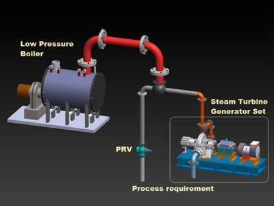
A biomass co-firing power plant is a specialized type of thermal power facility designed to generate electricity and, in many cases, heat by simultaneously burning biomass alongside conventional fossil fuels, most commonly coal, in existing or modified boiler systems. This approach leverages the existing infrastructure of coal-fired power plants while incorporating renewable biomass feedstocks, thereby reducing greenhouse gas emissions, enhancing fuel flexibility, and promoting sustainable energy production. The biomass used in co-firing can include wood chips, sawdust, bark, forestry residues, agricultural by-products such as straw and corn stover, energy crops, municipal green waste, and industrial organic residues. The proportion of biomass co-fired with coal can vary widely depending on plant design, boiler type, and regulatory or environmental requirements, typically ranging from a few percent to over 20% of the total fuel input, with higher percentages requiring more significant modifications to combustion and feeding systems.
Feedstock preparation is a critical component of biomass co-firing, as biomass properties differ significantly from coal in terms of moisture content, calorific value, density, particle size, and combustion characteristics. Uniform and properly sized biomass ensures stable combustion and prevents operational issues such as slagging, fouling, or uneven heat distribution. Preprocessing steps may include shredding, grinding, drying, screening, and pelletizing to achieve a consistent fuel suitable for feeding into the boiler. Feeding systems must be adapted or supplemented to handle biomass alongside coal, using conveyors, augers, pneumatic injectors, or dedicated biomass hoppers to ensure controlled and reliable fuel delivery. The challenge is to maintain synchronized combustion of both fuels, optimizing flame stability, heat release, and emission performance while minimizing disruptions to the existing coal-fired system.
The combustion process in a biomass co-firing plant can take place in several configurations depending on the boiler type and plant design. Direct co-firing introduces biomass directly into the main coal burner or furnace, where both fuels combust simultaneously on the same grate or in suspension, depending on whether the system uses a pulverized coal-fired or stoker-fired boiler. Indirect co-firing involves converting biomass into a gaseous or liquid intermediary—such as pyrolysis oil, biogas, or syngas—which is then injected into the boiler along with coal, allowing for more precise control of combustion conditions and minimizing changes to the existing fuel handling system. Parallel co-firing operates with separate boilers or burners for biomass and coal, combining the generated steam or heat in a shared steam cycle or turbine system, offering operational flexibility and easier integration with existing plants. Regardless of the configuration, careful management of combustion temperature, flame stability, and residence time is necessary to ensure complete burnout of both coal and biomass, maximize energy extraction, and minimize unburned residues.
Heat transfer and steam generation in biomass co-firing plants rely on the existing boiler infrastructure, although modifications may be required to accommodate the different combustion characteristics of biomass. Economizers, superheaters, and reheaters recover as much thermal energy as possible, increasing boiler efficiency and steam quality. Economizers preheat incoming feedwater using residual flue gas heat, while superheaters and reheaters raise saturated steam to superheated conditions, improving turbine efficiency and reducing condensation losses in the blades. Material selection for boiler tubes and heat transfer surfaces is critical, as co-firing biomass can introduce additional corrosion and fouling risks due to alkali metals, chlorides, and acidic compounds in the biomass, which differ from coal flue gas chemistry. Anti-corrosion coatings, alloyed steels, and periodic cleaning or soot-blowing schedules are employed to protect boiler surfaces and maintain heat transfer efficiency over the plant’s operational life.
Operational control, monitoring, and safety systems are essential to manage the complexities of co-firing biomass with coal. Digital control systems monitor fuel feed rates, combustion air supply, furnace temperature, steam pressure, water levels, and flue gas composition to optimize combustion efficiency, minimize emissions, and maintain stable steam production. Safety systems address the risk of overpressure, low or high water levels, slagging, ash accumulation, and unburned fuel buildup, while automated shutdown sequences, alarms, and redundancies protect boilers, turbines, and downstream equipment. Water treatment is crucial to prevent scaling, corrosion, and deposition within the boiler and turbine systems, ensuring consistent steam quality and long-term operational reliability.
Residue and ash management in biomass co-firing plants requires careful consideration, as both coal and biomass produce bottom ash, fly ash, and char with differing chemical compositions and physical properties. Effective ash handling systems—including hoppers, silos, conveyors, and pneumatic transport mechanisms—allow continuous removal and safe disposal or reuse of residues. Many plants adopt circular economy practices, using biomass ash as a soil amendment, secondary fuel, or in construction materials, while coal ash may be processed for industrial applications. Co-firing can also reduce the total coal ash output while partially substituting renewable biomass, contributing to more sustainable waste management practices.
Emissions control in biomass co-firing plants focuses on maintaining regulatory compliance and minimizing environmental impact. Technologies such as electrostatic precipitators, baghouse filters, cyclones, and scrubbers reduce particulate emissions, while staged combustion, flue gas recirculation, and selective catalytic reduction systems mitigate nitrogen oxides and carbon monoxide. Co-firing biomass with coal generally reduces net carbon dioxide emissions due to the renewable nature of biomass, helping plants meet climate and sustainability targets without requiring complete redesign of the existing coal-fired infrastructure. Proper integration of emissions control strategies, coupled with careful monitoring of fuel characteristics and combustion conditions, ensures that biomass co-firing plants operate efficiently, safely, and with a reduced environmental footprint.
Biomass co-firing power plants provide a practical and cost-effective pathway for transitioning conventional fossil fuel-based power generation toward renewable energy integration. By leveraging existing coal-fired boilers, turbines, and grid infrastructure, co-firing allows utilities and industries to incorporate biomass as a renewable fuel source with minimal disruption, providing immediate reductions in greenhouse gas emissions, increased fuel diversity, and enhanced energy security. Co-firing also encourages sustainable use of locally available biomass, promotes circular economy practices, and enables flexibility to adjust biomass-to-coal ratios according to feedstock availability, market conditions, and regulatory requirements. With proper design, operational control, feedstock preparation, and emissions management, biomass co-firing plants can deliver reliable, efficient, and environmentally responsible energy generation while supporting the transition to a low-carbon energy future.
A biomass co-firing power plant operates as a hybrid energy system that combines the combustion of conventional fossil fuels, most often coal, with a proportion of renewable biomass materials, allowing existing power generation infrastructure to incorporate renewable energy while reducing greenhouse gas emissions and diversifying fuel sources. These plants are designed to maintain high efficiency and operational reliability while using locally available biomass feedstocks such as wood chips, sawdust, bark, forestry residues, agricultural by-products including straw, corn stover, and husks, energy crops, municipal organic waste, and selected industrial residues. The co-firing ratio, which represents the proportion of biomass relative to coal, varies according to boiler design, feedstock characteristics, and environmental regulations, typically ranging from 5% to 20% of the total fuel input, although some facilities operate at higher percentages with advanced modifications to fuel handling and combustion systems. Careful attention to feedstock preparation is essential because biomass properties—moisture content, particle size, calorific value, density, and ash chemistry—differ significantly from coal. Shredding, grinding, drying, screening, and pelletizing are commonly employed to produce a consistent and uniform fuel suitable for controlled co-combustion, ensuring stable flame characteristics, uniform heat release, and predictable steam generation for electricity production or combined heat and power applications.
Fuel feeding and combustion systems in co-firing plants are designed to accommodate the simultaneous use of coal and biomass. Direct co-firing involves injecting biomass directly into existing coal burners or onto the coal-fired grate, where both fuels combust together, sharing the same furnace environment and heat transfer surfaces. This configuration requires careful synchronization of fuel feed rates and air supply to ensure stable combustion, prevent localized overheating, and avoid slagging or fouling caused by the distinct ash properties of biomass. Indirect co-firing methods convert biomass into a gaseous or liquid intermediary, such as pyrolysis oil, syngas, or biogas, which is then injected into the boiler alongside coal. This allows more precise control over combustion conditions, minimizes disruptions to the existing coal feed system, and enables higher percentages of renewable fuel without extensive retrofitting. Parallel co-firing utilizes separate burners or smaller auxiliary boilers dedicated to biomass while maintaining the primary coal-fired system, combining generated steam or heat in a shared cycle, allowing greater operational flexibility and easier integration of variable biomass feedstocks without compromising the performance of the main plant.
Heat transfer and steam generation in a biomass co-firing plant rely on existing boiler and turbine systems, often with modifications to accommodate biomass combustion characteristics. Economizers, superheaters, and reheaters optimize the extraction of thermal energy from the mixed fuel combustion process, preheating feedwater, increasing steam temperature, and reheating partially expanded steam to improve overall plant efficiency. Biomass can introduce additional corrosion and fouling risks due to alkali metals, chlorides, and acidic compounds in its ash, which differ from coal flue gas chemistry. Boiler materials are selected to resist these effects, using corrosion-resistant alloys, protective coatings, and optimized tube arrangements, while regular cleaning and soot-blowing schedules prevent performance degradation and maintain consistent heat transfer rates. The high-pressure, high-temperature steam produced is directed to steam turbines or, in CHP configurations, to combined heat and power systems, where it drives generators or provides process heat for industrial, agricultural, or district heating applications.
Operational control and monitoring in biomass co-firing plants are crucial for maintaining combustion stability, energy efficiency, and environmental compliance. Digital control systems continuously monitor fuel feed rates, furnace temperature, combustion air supply, steam pressure and temperature, water levels, and flue gas composition, allowing real-time adjustments to optimize performance. Safety systems protect against overpressure, low or high water levels, ash accumulation, slagging, and potential fuel blockages, with automated shutdown sequences and alarms ensuring protection of boilers, turbines, and downstream systems. Water treatment is equally important to maintain high-quality steam, prevent scaling and corrosion, and ensure long-term reliability of both the boiler and connected turbine or heat exchangers. Proper management of operational parameters is essential to accommodate variations in biomass properties, especially when co-firing with coal, where differing burn rates, moisture content, and ash composition can create dynamic combustion conditions.
Residue and ash management in biomass co-firing plants is another critical aspect of operation. Both coal and biomass produce bottom ash, fly ash, and char, which differ in chemical composition, particle size, and behavior. Effective ash handling systems—including silos, hoppers, conveyors, and pneumatic transport—enable continuous removal of residues, minimizing operational interruptions and facilitating safe disposal or reuse. Many facilities implement circular economy approaches, repurposing biomass ash for soil amendment, secondary fuel, or construction materials, while coal ash may be applied in industrial or civil engineering uses. Co-firing reduces overall coal consumption and associated coal ash production while partially substituting renewable biomass, contributing to sustainable waste management practices and reducing the environmental footprint of the power plant.
Emissions control in biomass co-firing power plants is critical to meet environmental regulations and reduce pollutants such as particulate matter, carbon monoxide, nitrogen oxides, and volatile organic compounds. Technologies like cyclones, baghouse filters, electrostatic precipitators, and scrubbers remove particulate emissions, while staged combustion, flue gas recirculation, and selective catalytic reduction systems mitigate gaseous emissions. Biomass co-firing generally reduces net carbon dioxide emissions because of the renewable carbon content of the biomass, contributing to climate goals while utilizing existing coal-fired infrastructure. Careful integration of emissions control measures, combined with monitoring of combustion conditions, feedstock properties, and fuel blending ratios, ensures that co-firing plants operate efficiently, safely, and with a reduced environmental footprint.
Biomass co-firing power plants offer a practical pathway for utilities and industries to transition toward renewable energy without requiring complete replacement of existing coal-fired units. By leveraging existing boilers, turbines, and grid connections, these plants achieve immediate reductions in greenhouse gas emissions, diversify fuel sources, and increase energy security while maintaining operational reliability. The flexibility to adjust biomass-to-coal ratios based on feedstock availability, market conditions, and regulatory requirements enables optimized performance and cost efficiency. Proper design, fuel preparation, combustion management, heat recovery, residue handling, emissions control, and operational monitoring allow biomass co-firing power plants to deliver reliable, efficient, and environmentally responsible electricity and heat generation while supporting sustainable biomass utilization, circular resource management, and the broader transition to low-carbon energy systems.
A biomass co-firing power plant functions as a hybrid energy generation facility that integrates renewable biomass fuels into conventional fossil fuel-fired boilers, most commonly coal-fired systems, to produce electricity and, in some cases, heat for combined heat and power (CHP) applications. This approach allows utilities and industrial operators to utilize existing power generation infrastructure while significantly reducing carbon emissions, diversifying fuel sources, and promoting the sustainable use of locally available biomass. The biomass feedstocks employed in co-firing can be highly diverse, ranging from wood chips, sawdust, and bark to forestry residues, agricultural by-products such as straw, corn stover, husks, energy crops, municipal green waste, and selected organic industrial residues. Each type of biomass exhibits distinct properties, including calorific value, moisture content, particle size, bulk density, and ash composition, which directly influence combustion behavior, heat release, slagging tendencies, and residue characteristics. Effective preprocessing—through shredding, grinding, drying, screening, and occasionally pelletizing—is essential to produce a uniform fuel that can be reliably handled, fed into the boiler, and combusted efficiently alongside coal, maintaining stable flame conditions and consistent steam generation for electricity and thermal applications.
The combustion systems in biomass co-firing power plants are designed to accommodate the simultaneous use of coal and biomass while maintaining optimal thermal performance. Direct co-firing involves feeding biomass directly into existing coal burners or onto coal grates, allowing the fuels to combust together in the same furnace. This configuration requires careful balancing of fuel feed rates and air supply to ensure uniform combustion, prevent localized hot spots, and minimize slagging and fouling, which can arise from the chemical differences in biomass ash compared to coal ash. Indirect co-firing, in contrast, converts biomass into a gaseous or liquid intermediate, such as syngas or pyrolysis oil, which is then injected into the boiler alongside coal. This method allows greater flexibility and control over combustion conditions, reduces the risk of fouling, and permits higher biomass substitution ratios without extensive modifications to the existing coal-handling system. Parallel co-firing uses separate burners or auxiliary boilers to combust biomass independently while combining the steam or heat produced with the main coal-fired cycle, offering operational flexibility and accommodating fluctuating biomass availability without compromising overall plant performance.
Heat transfer and steam generation in biomass co-firing power plants rely on efficient utilization of existing boiler infrastructure, often with modifications to accommodate biomass combustion characteristics. Economizers, superheaters, and reheaters recover thermal energy from the mixed-fuel combustion process, preheating feedwater, increasing steam temperature, and reheating partially expanded steam to enhance turbine efficiency and reduce moisture content in low-pressure stages. Biomass combustion can introduce additional challenges due to the presence of alkali metals, chlorides, and acidic compounds in the ash, which increase the risk of boiler tube corrosion, fouling, and slagging. To mitigate these risks, boilers are constructed using corrosion-resistant materials, protective coatings, and optimized tube arrangements, and regular maintenance schedules—including soot blowing, cleaning, and inspection—are implemented to maintain heat transfer efficiency and prolong component life. The high-pressure, high-temperature steam produced is utilized in steam turbines for electricity generation or directed to CHP systems to provide industrial process heat, district heating, or greenhouse energy, maximizing overall plant efficiency and energy recovery.
Operational control and monitoring in biomass co-firing plants are critical to ensuring stable, efficient, and safe performance. Digital or semi-automated control systems continuously monitor key parameters such as fuel feed rates, furnace temperature, combustion air supply, steam pressure, water levels, and flue gas composition, enabling real-time adjustments to optimize combustion, steam production, and emissions performance. Safety systems protect against overpressure, low or high water levels, ash accumulation, slagging, and blockages, with automated shutdown procedures and alarms safeguarding both the boiler and downstream turbine or engine systems. Water treatment is essential to maintain high-quality steam, prevent scaling and corrosion, and extend the operational life of the plant’s components, ensuring reliability over long-term operation. Managing operational parameters becomes particularly important in co-firing plants, as biomass properties such as moisture content and ash chemistry can vary significantly, influencing combustion dynamics and requiring careful control to maintain stable energy output.
Residue management in biomass co-firing power plants is an integral part of plant operation. Combustion of coal and biomass generates bottom ash, fly ash, char, and other residues, which differ in composition, particle size, and handling characteristics. Efficient ash removal systems, including silos, hoppers, conveyors, and pneumatic transport, are implemented to prevent accumulation, blockages, or operational disruptions. Many plants employ circular economy strategies, reusing biomass ash as soil amendments, secondary fuel, or construction material, while coal ash can be processed for industrial applications. By partially substituting coal with biomass, co-firing reduces overall fossil fuel consumption, decreases coal ash production, and contributes to sustainable waste management, demonstrating both environmental and economic benefits.
Emissions control in biomass co-firing plants is critical to maintain regulatory compliance and minimize environmental impact. Particulate matter is typically reduced through the use of cyclones, baghouse filters, electrostatic precipitators, or wet scrubbers, while staged combustion, flue gas recirculation, and selective catalytic reduction help to control carbon monoxide, nitrogen oxides, and volatile organic compounds. The inclusion of biomass in the fuel mix lowers net carbon dioxide emissions due to the renewable carbon content of the biomass, supporting climate change mitigation objectives. Effective integration of emissions control systems, combined with careful monitoring of fuel characteristics, combustion parameters, and feedstock blending ratios, ensures that biomass co-firing plants operate efficiently, safely, and with a reduced environmental footprint.
Biomass co-firing power plants provide a cost-effective pathway for transitioning conventional coal-fired electricity generation toward renewable energy integration. By leveraging existing boilers, turbines, and grid infrastructure, co-firing allows for immediate reductions in carbon emissions while maintaining operational reliability and energy output. The flexibility to adjust the biomass-to-coal ratio based on feedstock availability, regulatory requirements, and operational goals enables operators to optimize performance, energy efficiency, and fuel costs. Careful attention to feedstock preparation, combustion management, heat recovery, residue handling, emissions mitigation, and operational monitoring ensures that biomass co-firing power plants deliver reliable electricity and heat while supporting sustainable biomass utilization, circular resource management, and a progressive shift toward low-carbon energy systems. By combining renewable biomass with traditional fossil fuels, these plants play a pivotal role in enhancing energy security, promoting environmental stewardship, and enabling a practical transition to cleaner energy production while maintaining the economic viability of existing power generation infrastructure.
A biomass co-firing power plant operates as a hybrid energy generation system that integrates renewable biomass materials with conventional fossil fuels, primarily coal, in existing or modified boiler infrastructure to produce electricity and, in many cases, heat for combined heat and power (CHP) applications. This configuration allows for a gradual and cost-effective transition toward renewable energy by leveraging the established thermal power generation infrastructure while reducing net carbon dioxide emissions, diversifying fuel sources, and promoting sustainable utilization of locally available biomass. The feedstocks utilized in co-firing are highly varied and may include wood chips, sawdust, bark, forestry residues, agricultural by-products such as straw, corn stover, husks, energy crops, municipal green waste, and selected organic residues from industrial processes. Each biomass type exhibits specific characteristics including calorific value, moisture content, particle size, bulk density, and ash chemistry, which significantly affect combustion behavior, heat release patterns, slagging tendencies, and residue formation. Effective preprocessing—through shredding, grinding, drying, screening, or pelletizing—is essential to achieve uniform fuel properties that can be reliably handled, fed into the boiler, and combusted efficiently alongside coal, maintaining flame stability, consistent heat release, and predictable steam production for electricity generation and thermal applications.
In biomass co-firing plants, fuel feeding and combustion systems are designed to accommodate the distinct physical and chemical properties of biomass in combination with coal. Direct co-firing introduces biomass directly into the existing coal-fired burners or onto the grate, allowing simultaneous combustion of both fuels in the same furnace space. This approach necessitates careful coordination of fuel feed rates, combustion air distribution, and temperature management to maintain uniform flame conditions, prevent local overheating, and reduce the risk of slagging, fouling, or corrosion caused by differences in ash composition between biomass and coal. Indirect co-firing, on the other hand, involves converting biomass into a gaseous or liquid intermediate, such as syngas or pyrolysis oil, which can then be injected into the boiler alongside coal. This method allows precise control over combustion conditions, minimizes boiler modification requirements, and enables higher biomass substitution ratios without adversely affecting boiler operation. Parallel co-firing employs dedicated biomass burners or auxiliary boilers to combust biomass separately, combining the generated heat or steam with that from the primary coal-fired system, offering operational flexibility, ease of feedstock management, and the ability to accommodate fluctuating biomass availability without compromising overall plant efficiency.
The thermal energy generated from the co-combustion of biomass and coal is transferred to water or steam in the boiler, where it is converted into high-pressure, high-temperature steam for turbines, engines, or CHP systems. Heat recovery and transfer optimization are achieved through the use of economizers, superheaters, and reheaters, which preheat feedwater, increase steam temperature, and reheat partially expanded steam to maximize energy efficiency, improve turbine performance, and reduce moisture in low-pressure stages. Biomass combustion can introduce additional challenges due to the presence of alkali metals, chlorides, and acidic compounds in the ash, which may increase corrosion, fouling, and slagging potential on boiler tubes and heat transfer surfaces. To mitigate these issues, boilers in co-firing plants are constructed with corrosion-resistant alloys, protective coatings, and optimized tube arrangements, while routine cleaning, soot-blowing, and maintenance schedules ensure sustained heat transfer efficiency and prolong component lifespan. The resulting steam is then utilized for electricity generation in steam turbines or for heat supply in CHP applications, including industrial process heating, district heating, and greenhouse energy, thereby maximizing the overall efficiency of the plant.
Operational control and monitoring are critical for maintaining the stability, efficiency, and safety of biomass co-firing power plants. Advanced digital control systems regulate fuel feed rates, combustion air, furnace temperatures, steam pressure, water levels, and flue gas composition, enabling real-time adjustments to optimize combustion performance and energy output. Safety mechanisms are employed to prevent overpressure, low or high water levels, ash accumulation, slagging, or fuel blockages, with automated shutdown procedures, alarms, and redundancies protecting both the boiler and downstream turbine or engine systems. Water treatment ensures the production of high-quality steam, prevents scaling and corrosion in boiler tubes and turbine components, and supports long-term operational reliability. Careful management of operational parameters is particularly important in co-firing plants because biomass properties such as moisture content, calorific value, and ash composition can vary significantly, influencing combustion dynamics and requiring adaptive control to maintain consistent energy production.
Residue and by-product management is a fundamental aspect of biomass co-firing plant operation. The combustion of coal and biomass produces bottom ash, fly ash, and char, which differ in chemical composition, particle size, and handling behavior. Effective ash removal systems, including silos, hoppers, conveyors, and pneumatic transport mechanisms, enable continuous residue extraction, preventing operational disruptions and maintaining boiler efficiency. Many facilities implement circular economy practices, reusing biomass ash as soil amendments, secondary fuel, or construction material, while coal ash may be applied in industrial or civil engineering applications. By partially substituting coal with biomass, co-firing reduces overall coal consumption, decreases coal ash production, and contributes to more sustainable waste management practices, enhancing the environmental performance of the power plant.
Emissions control in biomass co-firing plants is essential to comply with environmental regulations and minimize pollutants such as particulate matter, carbon monoxide, nitrogen oxides, sulfur oxides, and volatile organic compounds. Particulate emissions are reduced using cyclones, baghouse filters, electrostatic precipitators, or wet scrubbers, while staged combustion, flue gas recirculation, and selective catalytic reduction systems mitigate gaseous emissions. Co-firing biomass with coal lowers net carbon dioxide emissions due to the renewable carbon content of the biomass, supporting climate mitigation objectives while utilizing existing coal-fired infrastructure. Proper integration of emission control technologies, combined with careful monitoring of fuel characteristics, combustion conditions, and blending ratios, ensures that co-firing plants operate efficiently, safely, and with reduced environmental impact.
Biomass co-firing power plants provide a cost-effective and practical pathway for transitioning conventional coal-fired electricity generation toward renewable energy integration. By leveraging existing boilers, turbines, and grid connections, co-firing enables immediate reductions in greenhouse gas emissions while maintaining reliable energy output and operational stability. The ability to adjust the biomass-to-coal ratio based on feedstock availability, operational goals, and regulatory requirements allows operators to optimize energy efficiency, fuel costs, and environmental performance. Careful attention to feedstock preparation, combustion management, heat recovery, residue handling, emissions control, and operational monitoring ensures that biomass co-firing plants deliver dependable electricity and heat while promoting sustainable biomass utilization, circular resource management, and a gradual shift toward low-carbon energy systems. Through this integration of renewable biomass into existing coal-fired infrastructure, co-firing power plants play a pivotal role in advancing energy security, environmental stewardship, and the transition to cleaner, more sustainable energy production.
Biomass Torrefaction Power Plant
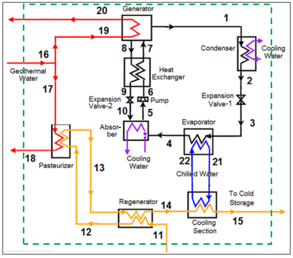
A biomass torrefaction power plant is an advanced energy facility designed to convert raw biomass into a higher-energy-density, uniform, and more storage-stable fuel through the process of torrefaction, followed by its use in electricity generation, heat production, or combined heat and power (CHP) systems. Torrefaction is a mild pyrolysis process carried out at temperatures typically between 200°C and 300°C in an oxygen-limited environment, which removes moisture and volatile organic compounds from the biomass while partially decomposing hemicellulose. The resulting torrefied biomass exhibits significantly improved properties compared to raw biomass: it has a higher calorific value, reduced moisture content, greater grindability, enhanced hydrophobicity for easier storage and transport, and a more uniform composition that allows for more predictable combustion or gasification behavior. Feedstocks suitable for torrefaction include wood chips, sawdust, bark, forestry residues, energy crops, agricultural residues such as straw and corn stover, and certain types of municipal or industrial organic waste. The variability of raw biomass in terms of particle size, moisture content, and chemical composition requires careful preprocessing—including drying, shredding, and screening—to ensure efficient torrefaction and consistent quality of the torrefied product.
In a biomass torrefaction power plant, the torrefaction reactor or furnace is the core component, typically designed for continuous or semi-continuous operation. Biomass is fed into the reactor at controlled rates, where it undergoes thermal treatment in the absence of oxygen, releasing water vapor and volatile organic compounds that are collected and often combusted or utilized as process heat within the plant. The torrefied biomass emerges as a dark, brittle, low-moisture product that is easier to pelletize or briquette for handling, transport, and storage. Because of its uniform and high-energy nature, torrefied biomass can be co-fired with coal in existing power plants or used in dedicated biomass combustion or gasification systems with higher efficiency and more stable flame characteristics than raw biomass. The energy content and predictable combustion behavior of torrefied biomass allow for improved boiler efficiency, reduced slagging and fouling, lower particulate emissions, and more flexible operational strategies in electricity and heat generation applications.
The combustion or gasification of torrefied biomass in a torrefaction power plant can be performed in multiple configurations. Fixed-bed and moving-grate boilers are commonly used for torrefied pellets or briquettes, providing controlled combustion with complete burnout and uniform heat release. Fluidized-bed systems allow for enhanced combustion uniformity, precise temperature control, and the ability to handle larger volumes of torrefied biomass with varying particle sizes. Gasification-based configurations convert torrefied biomass into a combustible syngas, which can then be used in internal combustion engines, microturbines, or small-scale gas turbines to generate electricity efficiently. The uniform calorific content, low moisture, and reduced volatile content of torrefied biomass make it easier to manage flame stability, residence time, and thermal output, which is particularly advantageous for plants seeking to integrate torrefied biomass into existing coal-fired or hybrid systems. Heat recovery systems, including economizers, superheaters, and reheaters, optimize energy utilization, allowing the production of high-pressure steam for turbines or low-pressure steam or hot water for CHP applications, thus maximizing the efficiency of the plant.
Operational control and monitoring are crucial for ensuring the stable and efficient performance of biomass torrefaction power plants. Advanced control systems regulate feedstock throughput, reactor temperature, residence time, and airflow within the torrefaction furnace, maintaining consistent torrefaction quality and preventing overheating or incomplete processing. Downstream combustion or gasification systems are monitored to manage furnace temperatures, combustion air supply, steam pressure, and flue gas composition, ensuring efficient energy conversion and compliance with environmental regulations. Safety mechanisms address potential risks such as overpressure, blockage in fuel feeding systems, dust explosions, and overheating of the torrefaction reactor. Water treatment, when used for steam generation, ensures proper feedwater quality to prevent scaling, corrosion, or operational degradation in boilers and turbines.
Residue and by-product management in a biomass torrefaction plant involves handling the volatiles released during torrefaction and any ash generated during combustion. Volatile compounds liberated in the torrefaction process can be collected and combusted for internal heat supply, improving overall plant efficiency and reducing external fuel requirements. Ash from the combustion of torrefied biomass is generally lower in quantity than raw biomass due to the removal of moisture and volatiles, and it can be handled using silos, hoppers, conveyors, or pneumatic systems for disposal or potential reuse as soil amendment, secondary fuel, or construction material. Effective residue management ensures continuous operation, minimizes maintenance downtime, and enhances environmental sustainability by reducing waste streams.
Emissions control in biomass torrefaction power plants is simplified by the improved combustion characteristics of torrefied biomass. Reduced moisture and volatile content lead to lower particulate emissions, more stable combustion, and decreased production of nitrogen oxides and carbon monoxide. Conventional emission control systems such as cyclones, bag filters, electrostatic precipitators, and wet scrubbers are employed as needed to meet regulatory standards, while staged combustion, flue gas recirculation, and temperature optimization further enhance emission performance. The high energy density and predictable behavior of torrefied biomass also allow for easier integration with existing coal-fired plants, enabling partial substitution of coal and contributing to significant reductions in net carbon dioxide emissions, supporting climate and sustainability goals.
Biomass torrefaction power plants offer a strategic advantage for renewable energy deployment, especially in regions with abundant low-grade biomass resources. By converting raw biomass into a higher-quality, energy-dense, and storage-stable fuel, torrefaction facilitates easier transport, longer storage periods, and reliable co-firing or dedicated biomass combustion in power plants. Torrefied biomass improves operational flexibility, enhances boiler or gasifier efficiency, reduces emissions, and enables consistent energy output. Combined with CHP integration, torrefaction power plants can deliver both electricity and thermal energy to industrial processes, district heating networks, or agricultural facilities. The modularity and scalability of torrefaction plants allow operators to adjust capacity based on feedstock availability, local energy demand, and grid requirements, while advanced monitoring and automated control systems ensure continuous optimization of fuel processing, combustion, heat recovery, emissions management, and residue handling. By transforming raw biomass into a higher-value, renewable energy feedstock, biomass torrefaction power plants contribute to sustainable energy systems, carbon footprint reduction, circular resource utilization, and reliable decentralized energy generation while enhancing the economics and environmental performance of both dedicated biomass and hybrid co-firing applications.
A biomass torrefaction power plant operates as an advanced renewable energy facility where raw biomass is thermally treated to produce a higher-energy-density, more uniform, and storage-stable fuel that can be used for electricity generation, heat production, or combined heat and power (CHP) applications. The torrefaction process is a mild pyrolysis conducted at temperatures between 200°C and 300°C in an oxygen-limited environment, which removes moisture and volatile compounds, partially decomposes hemicellulose, and improves the energy characteristics of the biomass. Raw feedstocks include wood chips, sawdust, bark, forestry residues, agricultural by-products such as straw and corn stover, energy crops, municipal green waste, and selected organic residues from industrial processes. Each type of biomass has distinct moisture content, calorific value, particle size, and ash composition, making preprocessing steps such as shredding, drying, grinding, and screening critical to ensure a consistent and efficient torrefaction process. The resulting torrefied biomass is dark, brittle, hydrophobic, and high in energy content, making it easier to store, transport, pelletize, and burn compared to untreated biomass, while also enabling more stable and predictable combustion behavior.
In a torrefaction power plant, the torrefaction reactor is central to the system, typically designed for continuous or semi-continuous operation. Biomass is fed into the reactor at controlled rates where it undergoes thermal treatment, releasing water vapor and volatile organic compounds, which can be captured and combusted to supply process heat, improving overall plant efficiency. The torrefied biomass is then collected and either pelletized or briquetted for uniformity and ease of handling. Because torrefied biomass has a higher energy density and improved grindability, it can be co-fired with coal in existing power plants, used in dedicated biomass boilers, or gasified for electricity generation. This enhanced fuel quality reduces operational issues such as slagging, fouling, and unburned carbon, improves flame stability, and allows for more precise control of combustion or gasification temperatures, making energy conversion more efficient and environmentally friendly.
The energy conversion stage in a torrefaction power plant can involve combustion or gasification depending on plant design and the desired energy output. Fixed-bed and moving-grate boilers are commonly used for burning torrefied pellets or briquettes, providing steady heat release and complete fuel burnout, while fluidized-bed boilers offer enhanced combustion uniformity, temperature control, and the capacity to handle a range of particle sizes and feedstock characteristics. Gasification systems can convert torrefied biomass into syngas, which is then used in internal combustion engines, microturbines, or small-scale gas turbines to generate electricity efficiently. Heat recovery systems, including economizers, superheaters, and reheaters, maximize energy extraction by preheating feedwater, superheating steam, and reheating partially expanded steam, thereby improving turbine efficiency and ensuring high-quality steam for both electricity generation and CHP applications. Torrefied biomass, with its reduced moisture and uniform composition, contributes to lower particulate emissions, more stable flame characteristics, and consistent thermal output, simplifying both operational management and emissions control.
Operational control in a torrefaction power plant is crucial to ensure process stability, energy efficiency, and safety. Advanced monitoring systems regulate feedstock throughput, reactor temperature, residence time, and airflow within the torrefaction furnace to maintain consistent product quality, while downstream combustion or gasification systems are continuously monitored for furnace temperature, combustion air supply, steam pressure, and flue gas composition. Safety mechanisms address risks such as overpressure, dust explosions, blockages in fuel feed systems, and overheating of torrefaction reactors, while automated alarms and shutdown procedures protect both the torrefaction and energy conversion components. Water treatment systems are essential in plants that generate steam to prevent scaling, corrosion, and degradation of boiler tubes and turbines, thereby maintaining long-term operational reliability and energy conversion efficiency.
Residue management in a biomass torrefaction power plant involves handling ash generated from combustion as well as volatile organic compounds released during torrefaction. The volatiles can be collected and combusted to supply internal process heat, improving overall efficiency and reducing external fuel requirements. Ash resulting from torrefied biomass combustion is generally lower in quantity and easier to handle than that from raw biomass due to the reduction of moisture and volatiles. Ash handling systems, including silos, hoppers, conveyors, or pneumatic transport, facilitate continuous removal, safe storage, and potential reuse in construction materials, soil amendment, or as secondary fuel, supporting sustainable and environmentally responsible plant operation. Efficient residue management prevents operational disruptions, maintains boiler and gasifier performance, and reduces the environmental footprint of the plant.
Emissions control in biomass torrefaction power plants benefits from the improved combustion characteristics of the torrefied biomass. Lower moisture content and reduced volatile matter result in decreased particulate emissions, more stable flame conditions, and lower production of carbon monoxide, nitrogen oxides, and volatile organic compounds. Conventional flue gas cleaning technologies such as cyclones, baghouse filters, electrostatic precipitators, and scrubbers are employed as necessary to meet environmental standards, while staged combustion, flue gas recirculation, and precise temperature control further enhance emission performance. The integration of torrefied biomass in co-firing with coal reduces net carbon dioxide emissions, supporting climate change mitigation objectives and improving the sustainability profile of existing power generation infrastructure.
Biomass torrefaction power plants provide significant operational and environmental advantages, particularly in regions with abundant low-grade biomass resources. By upgrading raw biomass into a higher-energy-density, storage-stable, and easily transportable fuel, torrefaction facilitates logistics, enables longer-term fuel storage, and improves reliability and predictability in energy generation. Torrefied biomass supports efficient and flexible operation in both dedicated biomass boilers and co-firing applications with coal, while also enabling integration with CHP systems to supply industrial, district heating, or agricultural process heat. Modular and scalable plant designs allow operators to adjust capacity based on feedstock availability, local energy demand, and grid requirements, while advanced monitoring and automated control systems ensure continuous optimization of torrefaction, combustion, heat recovery, emissions management, and residue handling. By transforming low-grade biomass into a high-value renewable energy feedstock, biomass torrefaction power plants contribute to sustainable energy production, reduced carbon footprint, circular resource utilization, and reliable decentralized energy generation, offering a practical and efficient solution for integrating renewable biomass into modern power systems.
A biomass torrefaction power plant functions as a sophisticated renewable energy facility that upgrades raw biomass into a high-energy-density, uniform, and hydrophobic fuel through torrefaction, which can then be efficiently used for electricity generation, heat production, or combined heat and power (CHP) applications. The torrefaction process involves heating biomass to moderate temperatures, typically between 200°C and 300°C, in an oxygen-limited environment, which removes moisture and volatile organic compounds, partially decomposes hemicellulose, and improves the fuel’s calorific value, grindability, and storage characteristics. Feedstocks used in such plants are highly diverse, including wood chips, sawdust, bark, forestry residues, agricultural by-products such as straw and corn stover, energy crops, municipal green waste, and selected industrial organic residues. Each type of biomass exhibits unique properties in terms of moisture content, calorific value, particle size, density, and ash composition, necessitating preprocessing steps like drying, shredding, grinding, and screening to ensure consistent torrefaction, uniform particle size, and optimal thermal performance. The resulting torrefied biomass is brittle, hydrophobic, and more energy-dense than raw biomass, making it easier to pelletize, transport, store for extended periods, and combust with greater stability and predictability than untreated feedstock.
In operation, the torrefaction reactor is the heart of the plant, typically designed for continuous or semi-continuous processing. Biomass is fed at a controlled rate into the reactor, where it is heated in an oxygen-limited environment, driving off water and volatile compounds. These volatiles are often collected and combusted to supply process heat for the torrefaction reactor itself, improving energy efficiency and minimizing external fuel requirements. The torrefied biomass emerges as a dark, brittle product suitable for pelletization or briquetting, producing a standardized fuel that can be co-fired with coal in existing power plants or used in dedicated biomass combustion or gasification systems. The high energy density and low moisture content of torrefied biomass enhance flame stability, reduce slagging and fouling, and provide more predictable heat release, simplifying combustion control and allowing more efficient operation of boilers, turbines, or CHP systems.
Energy conversion in a biomass torrefaction power plant can be achieved through several configurations depending on plant design and objectives. Fixed-bed or moving-grate boilers are commonly used to combust torrefied pellets or briquettes, offering uniform heat distribution and high fuel burnout rates, while fluidized-bed systems provide precise temperature control, enhanced combustion uniformity, and the capacity to handle variable particle sizes and feedstock properties. Torrefied biomass can also be used in gasification systems to produce syngas, which is then employed in internal combustion engines, microturbines, or small-scale gas turbines to generate electricity with high efficiency. Heat recovery systems, including economizers, superheaters, and reheaters, optimize energy capture from the combustion process, preheating feedwater, superheating steam, and reheating partially expanded steam to maximize turbine efficiency and produce high-quality steam for both electricity generation and CHP applications. Torrefied biomass allows for smoother flame behavior, lower moisture content, and a more uniform combustion process, which contributes to reduced emissions, higher energy efficiency, and simplified plant operation.
Operational monitoring and control are critical for maintaining the stability, efficiency, and safety of biomass torrefaction power plants. Advanced control systems regulate feedstock throughput, reactor temperature, residence time, and airflow within the torrefaction reactor, ensuring consistent product quality and preventing overheating or incomplete processing. Downstream combustion or gasification systems are monitored continuously for furnace temperature, combustion air distribution, steam pressure, and flue gas composition, allowing real-time adjustments that optimize thermal efficiency, combustion stability, and emissions performance. Safety systems address potential risks such as overpressure, dust explosions, fuel blockages, or overheating of torrefaction reactors, while automated alarms and shutdown protocols protect both the torrefaction and energy conversion processes. When the plant generates steam, water treatment systems ensure proper feedwater quality, preventing scaling, corrosion, or operational degradation in boilers and turbines and maintaining long-term reliability.
Residue and by-product management in a biomass torrefaction plant is a vital part of the operational cycle. Volatiles released during torrefaction can be captured and combusted to provide process heat, improving overall plant efficiency and reducing external energy requirements. Ash generated from torrefied biomass combustion is typically lower in quantity and more homogeneous than that from untreated biomass due to the removal of moisture and volatiles. Efficient ash handling systems, including silos, hoppers, conveyors, and pneumatic transport mechanisms, facilitate continuous removal, safe storage, and potential reuse of ash in soil amendment, construction materials, or as secondary fuel. Proper management of residues ensures uninterrupted operation, protects equipment from corrosion and fouling, and supports environmental compliance and sustainability goals.
Emissions control in biomass torrefaction power plants benefits from the improved combustion characteristics of torrefied biomass. Lower moisture content and reduced volatile matter result in decreased particulate emissions, more stable flame behavior, and lower production of nitrogen oxides, carbon monoxide, and volatile organic compounds. Standard flue gas treatment technologies, such as cyclones, baghouse filters, electrostatic precipitators, and wet scrubbers, are applied as needed to meet environmental standards, while combustion optimization techniques like staged combustion, flue gas recirculation, and precise temperature management further reduce pollutant formation. When torrefied biomass is co-fired with coal, the overall carbon footprint of the plant is reduced because the renewable carbon in biomass partially offsets fossil fuel emissions, supporting climate and sustainability objectives without requiring a complete replacement of existing power generation infrastructure.
Biomass torrefaction power plants offer considerable advantages in operational flexibility, environmental performance, and fuel logistics. By converting low-grade, high-moisture biomass into a higher-quality, energy-dense, and storage-stable fuel, these plants facilitate long-term storage, transport, and consistent energy generation. Torrefied biomass can be integrated into existing coal-fired or dedicated biomass boilers, gasifiers, or CHP systems, providing reliable and predictable combustion with improved efficiency and reduced emissions. Modular and scalable plant designs allow operators to adjust capacity according to biomass availability, local energy demand, and grid requirements. Advanced monitoring, automated control systems, and optimized feedstock management ensure continuous improvement of torrefaction, combustion, heat recovery, emissions control, and residue handling. By transforming raw biomass into a premium renewable energy feedstock, biomass torrefaction power plants support circular resource utilization, reduce dependence on fossil fuels, enhance energy security, and enable a transition to low-carbon, sustainable, and decentralized energy systems, making them an increasingly important technology in modern renewable power generation.
A biomass torrefaction power plant operates as a cutting-edge renewable energy facility in which raw biomass is converted into a more energy-dense, uniform, and hydrophobic fuel through torrefaction, which is then used for electricity generation, heat production, or combined heat and power (CHP) applications. Torrefaction is a mild pyrolysis process performed at temperatures typically between 200°C and 300°C in an oxygen-limited environment, where moisture and volatile organic compounds are driven off, hemicellulose is partially decomposed, and the resulting fuel gains significantly improved calorific value, grindability, and storage stability. The raw feedstocks for torrefaction power plants are highly varied and include wood chips, sawdust, bark, forestry residues, energy crops, agricultural residues such as straw and corn stover, municipal green waste, and select industrial organic residues. Each biomass type differs in moisture content, particle size, calorific value, density, and ash composition, which necessitates careful preprocessing through drying, shredding, grinding, and screening to produce a uniform feedstock suitable for torrefaction and efficient combustion or gasification. After torrefaction, the biomass becomes brittle, hydrophobic, and high in energy content, enabling easier pelletization, storage, transport, and handling while also improving combustion predictability and stability compared to raw biomass.
The core of a biomass torrefaction power plant is the torrefaction reactor, which is typically designed for continuous or semi-continuous operation. Biomass is fed into the reactor at controlled rates, where it is heated in an oxygen-limited environment, causing water and volatile organic compounds to vaporize. These volatiles are often captured and combusted to supply process heat for the torrefaction reactor itself, increasing overall energy efficiency and reducing the need for external fuel. The resulting torrefied biomass is collected and often pelletized or briquetted to create a standardized fuel with consistent energy content, size, and handling characteristics. Because of its improved thermal properties and uniform composition, torrefied biomass can be co-fired with coal in existing thermal power plants or utilized in dedicated biomass combustion or gasification systems with higher efficiency, more stable flame behavior, reduced slagging and fouling, and lower particulate emissions. The uniformity of torrefied biomass also facilitates better control over combustion temperature, residence time, and energy output, which is particularly advantageous for integration into existing infrastructure and CHP applications.
Energy conversion in torrefaction power plants can be achieved through a variety of configurations depending on plant objectives and scale. Fixed-bed or moving-grate boilers are commonly used to combust torrefied pellets or briquettes, offering uniform combustion, complete fuel burnout, and stable heat release. Fluidized-bed boilers provide precise temperature control, enhanced combustion uniformity, and the ability to handle a wider range of particle sizes and feedstock variations, which is particularly useful when dealing with heterogeneous biomass streams. In gasification-based configurations, torrefied biomass is converted into a combustible syngas, which is then used in internal combustion engines, microturbines, or small-scale gas turbines to produce electricity efficiently. Heat recovery systems, including economizers, superheaters, and reheaters, are incorporated to maximize energy extraction, preheating feedwater, superheating steam, and reheating partially expanded steam to improve turbine efficiency, while simultaneously supplying high-quality steam for electricity generation, industrial processes, or district heating. The improved energy density and reduced moisture content of torrefied biomass contribute to smoother flame behavior, higher boiler efficiency, and reduced emissions compared to untreated biomass, enabling more reliable and efficient operation across multiple energy conversion configurations.
Operational control in biomass torrefaction power plants is critical for maintaining consistent performance, efficiency, and safety. Advanced monitoring systems manage feedstock throughput, reactor temperature, residence time, and airflow within the torrefaction unit, ensuring uniform fuel quality and preventing overheating or incomplete processing. Downstream combustion or gasification systems are continuously monitored for furnace temperature, air supply, steam pressure, and flue gas composition, with automated adjustments made in real time to optimize thermal efficiency and maintain emission compliance. Safety systems are installed to prevent overpressure, dust explosions, fuel feed blockages, and reactor overheating, while alarms and automatic shutdown procedures safeguard both torrefaction and energy conversion systems. When the plant generates steam, water treatment is essential to produce high-quality feedwater, preventing scaling, corrosion, and degradation of boilers and turbines and ensuring long-term operational reliability.
Residue management is an integral part of biomass torrefaction plant operations. Volatiles released during torrefaction are captured and combusted to supply internal process heat, reducing external energy requirements and improving overall plant efficiency. Ash generated from the combustion of torrefied biomass is generally lower in quantity, more uniform, and easier to handle than ash from untreated biomass due to the removal of moisture and volatile compounds during torrefaction. Ash handling systems, including silos, hoppers, conveyors, and pneumatic transport, enable continuous removal and safe storage, while also allowing for potential reuse in applications such as soil amendment, secondary fuel, or construction material. Effective management of residues ensures uninterrupted operation, prevents equipment fouling, and supports environmental compliance and sustainability goals.
Emissions control in biomass torrefaction power plants benefits significantly from the improved combustion characteristics of torrefied biomass. Reduced moisture and volatile content lead to lower particulate emissions, more stable flame behavior, and decreased production of nitrogen oxides, carbon monoxide, and volatile organic compounds. Conventional emission control technologies such as cyclones, baghouse filters, electrostatic precipitators, and wet scrubbers are applied as necessary to meet environmental regulations, while combustion optimization techniques including staged combustion, flue gas recirculation, and precise temperature management further improve emission performance. When torrefied biomass is co-fired with coal, the renewable carbon content contributes to lower net carbon dioxide emissions, supporting climate mitigation objectives and enabling a smoother transition to low-carbon energy systems without fully replacing existing fossil fuel infrastructure.
Biomass torrefaction power plants offer multiple operational and environmental advantages, including improved fuel logistics, enhanced combustion stability, higher energy efficiency, and lower emissions. By converting raw biomass into a high-quality, energy-dense, and storage-stable fuel, torrefaction simplifies transport, storage, and handling while enabling reliable and predictable energy generation. Torrefied biomass can be integrated into existing coal-fired plants, dedicated biomass boilers, or gasification systems, supporting both electricity generation and CHP applications for industrial, district heating, and agricultural needs. Modular and scalable plant designs allow operators to adjust capacity according to biomass availability, energy demand, and grid requirements, while advanced monitoring, automation, and process control ensure optimal torrefaction, combustion, heat recovery, emissions management, and residue handling. By transforming low-grade biomass into a premium renewable energy feedstock, biomass torrefaction power plants contribute to sustainable energy production, reduced carbon footprint, circular resource utilization, enhanced energy security, and reliable decentralized energy generation, establishing themselves as a key technology in modern renewable energy systems.
Advanced Biomass Conversion Plant
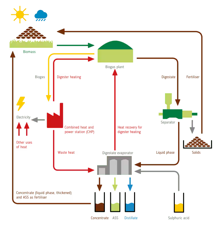
An advanced biomass conversion plant represents a highly integrated renewable energy facility designed to transform various types of biomass into usable energy carriers such as electricity, heat, biofuels, or syngas through sophisticated thermal, biochemical, and chemical conversion technologies. Unlike conventional biomass power plants, advanced biomass conversion plants employ multiple complementary processes, including torrefaction, pyrolysis, gasification, anaerobic digestion, and hydrothermal liquefaction, to optimize the energy yield, reduce emissions, and create value-added co-products. These plants are capable of handling a wide variety of feedstocks, from wood chips, sawdust, bark, forestry residues, and agricultural residues such as straw, corn stover, and husks, to energy crops, municipal green waste, and select industrial organic residues. Each feedstock exhibits distinct physical and chemical properties—including moisture content, calorific value, particle size, ash composition, and chemical makeup—that necessitate preprocessing such as drying, shredding, grinding, pelletizing, and screening to achieve a uniform and consistent material suitable for downstream conversion processes. Advanced preprocessing ensures efficient handling, transport, and storage while enabling high-efficiency conversion with predictable energy output and reduced operational challenges.
The core operations of an advanced biomass conversion plant are centered on maximizing the utilization of the chemical energy stored in biomass while minimizing environmental impact. In thermal conversion processes, torrefaction and pyrolysis upgrade the biomass to energy-dense solid or liquid fuels that are easier to store, transport, and combust, while gasification converts biomass into a combustible syngas consisting primarily of carbon monoxide, hydrogen, and methane, suitable for driving turbines, engines, or producing synthetic fuels. Anaerobic digestion processes convert wet organic biomass, including food waste and sewage sludge, into biogas through microbial activity, providing a renewable source of methane for electricity or heat generation. Hydrothermal liquefaction and fast pyrolysis produce bio-oils, which can be refined into transportation fuels or used as industrial heating fuels. The integration of multiple conversion technologies allows these plants to process a diverse feedstock portfolio, achieve high overall energy efficiency, and provide flexibility in energy output, including electricity, process heat, district heating, or chemical feedstocks for industrial use.
Energy recovery and heat integration are critical components of advanced biomass conversion plants. High-temperature conversion processes such as gasification and pyrolysis produce hot gases, char, and bio-oils that require efficient heat recovery systems, including superheaters, economizers, and heat exchangers, to optimize the generation of steam, hot water, or preheated feedstock for other processes. Advanced combustion and gas cleaning technologies are applied to reduce particulate emissions, nitrogen oxides, sulfur oxides, and volatile organic compounds, ensuring regulatory compliance and minimizing environmental impact. In CHP configurations, recovered heat is utilized for industrial processes, district heating, or greenhouse applications, maximizing overall energy efficiency. Additionally, integrated energy storage solutions, such as hot water tanks, thermal oil storage, or biochar stockpiles, allow continuous operation and flexibility to match fluctuating electricity and heat demand while stabilizing plant operations.
Operational control in advanced biomass conversion plants is highly sophisticated due to the complexity and diversity of the conversion processes and feedstock characteristics. Digital and automated control systems monitor feedstock input, reactor temperature, residence time, gas composition, combustion efficiency, steam production, and emissions in real time, enabling adaptive management of the conversion processes. Advanced sensors, predictive algorithms, and process modeling allow operators to optimize conversion efficiency, maintain stable energy output, and prevent operational issues such as reactor fouling, slagging, gas contamination, or thermal imbalances. Safety systems are integrated throughout the plant to prevent overpressure, dust or gas explosions, blockages, and overheating, while automated shutdown procedures, alarms, and redundancies ensure personnel and equipment protection. Water and steam quality management is essential in thermal conversion systems, preventing scaling, corrosion, or efficiency loss in turbines, boilers, and heat exchangers.
Residue and by-product management is an integral aspect of advanced biomass conversion plants. Ash, char, and biochar produced in thermal processes can be collected and repurposed as soil amendments, fertilizers, construction materials, or secondary fuels. Volatile gases and bio-oils can be recovered and used as process fuel or chemical feedstocks, creating a circular resource utilization loop. In anaerobic digestion systems, digestate is often dewatered and used as a nutrient-rich fertilizer, contributing to sustainable agriculture. Efficient residue handling systems, including conveyors, hoppers, silos, pneumatic transport, and automated removal, ensure uninterrupted operation while minimizing maintenance requirements and environmental impact.
Emissions control in advanced biomass conversion plants benefits from integrated, multi-stage cleaning systems designed to handle both particulate matter and gaseous pollutants. Cyclones, baghouses, electrostatic precipitators, scrubbers, and catalytic converters are commonly applied to ensure compliance with air quality standards. Gasification and pyrolysis processes produce a syngas or bio-oil stream that can be cleaned to remove tars, particulates, and other contaminants, enhancing downstream energy conversion efficiency and reducing environmental emissions. The use of renewable biomass feedstocks inherently reduces net carbon dioxide emissions compared to fossil fuels, supporting climate mitigation and sustainable energy goals.
Advanced biomass conversion plants provide significant environmental and economic advantages by enabling high-efficiency energy recovery from diverse and underutilized biomass resources. By combining multiple conversion technologies, these plants achieve higher overall energy efficiency than single-technology facilities, enhance fuel flexibility, reduce fossil fuel dependence, and create valuable co-products for agricultural, industrial, and chemical applications. Modular and scalable designs allow operators to adjust capacity, conversion methods, and energy outputs based on local feedstock availability, market demand, and regulatory requirements. Continuous monitoring, advanced process control, and integration of heat and energy recovery systems optimize operational efficiency, energy output, and environmental performance, while ensuring reliability and sustainability. Through the synergistic combination of torrefaction, pyrolysis, gasification, anaerobic digestion, and hydrothermal liquefaction, advanced biomass conversion plants transform raw organic materials into high-value energy, fuels, and chemicals, contributing to a circular economy, reduced carbon footprint, energy security, and the transition toward a low-carbon and sustainable energy infrastructure.
An advanced biomass conversion plant operates as a highly integrated renewable energy facility where raw biomass feedstocks are transformed into electricity, heat, biofuels, and other valuable energy carriers through a combination of thermal, biochemical, and chemical processes, achieving high overall energy efficiency and environmental performance. Unlike conventional biomass power plants, these facilities are designed to handle a broad spectrum of feedstocks, including wood chips, sawdust, bark, forestry residues, agricultural by-products such as straw, corn stover, and husks, energy crops, municipal green waste, and select industrial organic residues, each with unique moisture content, particle size, calorific value, density, and ash composition. To manage the heterogeneity of these materials, advanced preprocessing systems perform drying, shredding, grinding, screening, and pelletization, ensuring a uniform and manageable feedstock that optimizes conversion efficiency, reduces operational disturbances, and facilitates storage and transport. The resulting pretreated biomass can then undergo torrefaction, pyrolysis, gasification, anaerobic digestion, or hydrothermal liquefaction depending on plant design, producing fuels with higher energy density, improved combustion characteristics, or bio-chemical intermediates suitable for electricity, heat, or industrial applications.
At the core of an advanced biomass conversion plant, torrefaction and pyrolysis reactors upgrade raw biomass into higher-value solid and liquid fuels by removing moisture and volatiles, increasing energy density, and stabilizing the material for long-term storage and transportation. Gasification units convert biomass into syngas, a mixture of hydrogen, carbon monoxide, and methane, which can be combusted in gas engines, microturbines, or small-scale gas turbines to generate electricity efficiently, while also producing heat for CHP applications. Anaerobic digestion systems process wet organic biomass, including food waste and sewage sludge, to generate biogas through microbial activity, which is rich in methane and can serve as a renewable energy source. Hydrothermal liquefaction and fast pyrolysis produce bio-oils that can be refined into transportation fuels or utilized for industrial heating, providing additional flexibility in energy outputs and the creation of value-added co-products. The integration of multiple conversion processes within the same facility allows for optimized energy recovery, improved fuel flexibility, and the ability to adapt to variations in feedstock availability, composition, and moisture content, thereby enhancing operational reliability and plant efficiency.
Energy recovery and heat management are critical aspects of advanced biomass conversion plants, where waste heat from high-temperature processes such as pyrolysis, gasification, and combustion is captured and utilized to preheat feedstock, generate steam, or supply district heating. Heat recovery systems, including economizers, superheaters, reheaters, and advanced heat exchangers, maximize the energy extracted from combustion gases, increasing overall plant efficiency and enabling CHP integration. The production of high-pressure steam supports electricity generation through steam turbines, while recovered low-pressure steam or hot water can supply industrial processes, district heating networks, or greenhouse operations. By effectively integrating heat recovery and process optimization, these plants achieve higher overall energy utilization, reduce the need for external fuel inputs, and enhance the sustainability of energy production.
Operational control and automation in advanced biomass conversion plants are sophisticated due to the complexity of managing multiple feedstocks and conversion processes simultaneously. Digital monitoring systems oversee feedstock input, reactor temperature, residence time, gas composition, combustion efficiency, steam generation, and emissions in real time, allowing operators to adjust processes dynamically to maintain optimal energy output and efficiency. Predictive modeling and adaptive algorithms facilitate precise control of thermal conditions, residence times, and fuel blending, reducing the risks of slagging, fouling, incomplete conversion, or equipment degradation. Safety systems integrated across the plant prevent overpressure, dust explosions, gas leaks, and overheating, while automated shutdown procedures, alarms, and redundant controls ensure both personnel and equipment protection. Proper water and steam quality management is maintained to avoid scaling, corrosion, and efficiency loss in boilers, turbines, and heat exchangers, ensuring long-term operational stability.
Residue and by-product management is a fundamental component of advanced biomass conversion plants. Solid residues such as ash, char, and biochar from thermal processes can be repurposed as soil amendments, fertilizers, construction materials, or secondary fuels, contributing to circular resource use. Volatile compounds released during pyrolysis or torrefaction can be captured and combusted to supply process heat, reducing external fuel dependency and improving overall energy efficiency. In anaerobic digestion systems, digestate is often dewatered and utilized as a nutrient-rich fertilizer, creating additional value streams while minimizing waste. Efficient residue handling through silos, hoppers, conveyors, and pneumatic transport systems ensures uninterrupted operation, reduces maintenance requirements, and limits environmental impact, supporting sustainable and economically viable plant operation.
Emissions control in advanced biomass conversion plants is enhanced by the integration of multi-stage treatment systems designed to handle particulate matter, volatile organic compounds, nitrogen oxides, sulfur oxides, and other pollutants. Cyclones, baghouse filters, electrostatic precipitators, wet scrubbers, and catalytic converters are deployed as required to comply with stringent air quality regulations, while process optimization strategies such as staged combustion, flue gas recirculation, and precise temperature control further minimize emissions. The use of renewable biomass feedstocks inherently reduces net carbon dioxide emissions compared to fossil fuels, contributing to climate mitigation objectives and supporting the transition toward low-carbon energy systems. Co-firing torrefied or gasified biomass with fossil fuels further enhances environmental performance by reducing fossil fuel consumption while maintaining reliable energy output.
Advanced biomass conversion plants provide significant environmental, operational, and economic advantages by enabling high-efficiency energy recovery from diverse and underutilized biomass resources. By integrating multiple conversion technologies, these plants achieve higher overall energy efficiency than conventional single-process facilities, while enhancing fuel flexibility and resilience to feedstock variability. The modular and scalable design of such plants allows operators to adjust capacity, conversion methods, and energy outputs according to feedstock availability, market demands, and regulatory requirements. Continuous process monitoring, automated control systems, and optimized heat and energy recovery ensure operational efficiency, high energy yield, and minimal environmental impact. Through the combined application of torrefaction, pyrolysis, gasification, anaerobic digestion, and hydrothermal liquefaction, advanced biomass conversion plants transform raw organic materials into high-value energy carriers, fuels, and chemicals, supporting circular economy principles, reducing greenhouse gas emissions, enhancing energy security, and facilitating the transition to sustainable, low-carbon energy infrastructure while providing reliable electricity, heat, and bio-based products to meet diverse energy and industrial needs.
An advanced biomass conversion plant represents a highly integrated energy facility where diverse biomass feedstocks are transformed into electricity, heat, biofuels, and other valuable energy carriers through a combination of thermal, biochemical, and chemical processes, designed to maximize energy recovery, efficiency, and environmental performance. Unlike conventional biomass plants, these facilities can process a wide variety of raw materials including wood chips, sawdust, bark, forestry residues, agricultural by-products such as straw, corn stover, husks, energy crops, municipal green waste, and selected industrial organic residues, each with distinct properties such as moisture content, particle size, calorific value, ash composition, and density. To accommodate these variations, advanced preprocessing systems perform drying, shredding, grinding, screening, and sometimes pelletizing, ensuring a uniform and manageable feedstock that allows for consistent torrefaction, pyrolysis, gasification, or anaerobic digestion. These preprocessing steps are critical not only for operational efficiency but also for improving storage, transport, and handling of biomass, while enabling predictable performance in downstream energy conversion systems. The resulting treated biomass can then be upgraded through torrefaction or pyrolysis to produce higher-energy-density fuels, converted to syngas through gasification for electricity or CHP applications, or processed in hydrothermal liquefaction units to produce bio-oils suitable for industrial or transport use, with each pathway optimized to extract maximum energy and value from the feedstock.
At the core of the plant, torrefaction reactors and pyrolysis units operate to thermally treat biomass, removing moisture and volatiles, stabilizing the material, and increasing energy content, while gasification systems convert biomass into combustible syngas comprised of hydrogen, carbon monoxide, and methane, which can drive turbines, engines, or microturbines for electricity generation. Anaerobic digestion units complement the thermal processes by converting wet organic biomass, such as food waste or sewage sludge, into biogas, rich in methane for use in electricity generation, heating, or CHP systems. Hydrothermal liquefaction and fast pyrolysis units produce bio-oils, which serve as liquid fuels or feedstocks for chemical processes. By integrating multiple conversion technologies within the same facility, advanced biomass conversion plants can handle feedstock variability, optimize energy output, and provide flexible operation to meet both electricity and heat demand while producing value-added by-products. The combination of thermal, biochemical, and chemical conversion enables a nearly complete utilization of the chemical energy contained in the biomass, reduces waste, and enhances the overall sustainability of the energy production process.
Energy recovery and heat integration are critical to plant performance. High-temperature processes such as gasification and pyrolysis generate significant amounts of heat, which is recovered using economizers, superheaters, reheaters, and heat exchangers to preheat feedwater, generate steam, or supply hot water for industrial or district heating applications. Heat from volatile gases released during torrefaction or pyrolysis can be captured and redirected to maintain reactor temperatures or preheat biomass, improving overall efficiency and reducing the need for external fuel. Combined heat and power configurations maximize energy utilization by simultaneously producing electricity and useful thermal energy, while thermal storage systems—such as hot water tanks, thermal oil systems, or biochar stockpiles—allow for load balancing and continuous operation, ensuring a stable energy supply even when feedstock availability or energy demand fluctuates.
Operational control in advanced biomass conversion plants relies on sophisticated digital and automated monitoring systems that continuously track feedstock input, reactor temperature, residence time, gas composition, combustion efficiency, steam production, and emissions. Adaptive algorithms and predictive process modeling allow operators to optimize thermal conditions, adjust residence times, and blend fuels as needed to maintain consistent energy output, prevent fouling or slagging, and minimize equipment wear. Safety systems are integrated throughout the facility to prevent overpressure, dust explosions, gas leaks, and reactor overheating, while automatic shutdowns, alarms, and redundant control mechanisms protect both personnel and equipment. Water treatment and steam quality management are essential for maintaining boiler, turbine, and heat exchanger performance, preventing scaling, corrosion, or efficiency loss, and ensuring long-term operational stability.
Residue and by-product management is a key component of advanced biomass conversion plants. Solid residues, including ash, char, and biochar, can be collected and reused as soil amendments, fertilizers, construction materials, or secondary fuels, contributing to a circular economy. Volatile compounds released during thermal treatment can be captured and combusted to supply process heat, reducing external energy demands. In anaerobic digestion, digestate is often dewatered and repurposed as a nutrient-rich fertilizer. Efficient residue handling systems, including silos, hoppers, conveyors, and pneumatic transport, ensure continuous operation while minimizing environmental impact, maintenance requirements, and safety risks. Proper management of these by-products not only supports sustainability goals but also enhances the economic viability of the plant by creating additional revenue streams.
Emissions control in advanced biomass conversion plants is enhanced by multi-stage gas cleaning and filtration systems designed to capture particulate matter, volatile organic compounds, nitrogen oxides, sulfur oxides, and other pollutants. Technologies such as cyclones, baghouse filters, electrostatic precipitators, wet scrubbers, and catalytic converters are applied as needed, while process optimization strategies, including staged combustion, flue gas recirculation, and precise temperature control, reduce the formation of emissions at the source. When torrefied biomass, gasified biomass, or syngas is co-fired with fossil fuels, the renewable content reduces overall carbon dioxide emissions, supporting climate mitigation objectives and promoting a transition to low-carbon energy systems without requiring full replacement of existing infrastructure. The improved combustion characteristics of upgraded biomass fuels contribute to lower particulate emissions, more stable flame behavior, and more predictable thermal output, making emissions management more reliable and efficient.
Advanced biomass conversion plants provide significant environmental, operational, and economic advantages by enabling high-efficiency energy recovery from underutilized or low-grade biomass resources. By combining multiple conversion technologies within a single integrated facility, these plants achieve higher energy efficiency than conventional single-process plants, allow for flexible adaptation to feedstock availability and quality, and produce multiple energy carriers, including electricity, heat, biofuels, and syngas, alongside valuable by-products such as biochar and digestate. Modular and scalable designs allow operators to tailor plant capacity and conversion pathways to meet local energy demand, market opportunities, and regulatory requirements. Through continuous process monitoring, automated control systems, optimized heat and energy recovery, and effective residue and emissions management, advanced biomass conversion plants can reliably deliver renewable energy with high efficiency, low environmental impact, and sustainable resource utilization. By transforming diverse biomass feedstocks into high-value energy, fuels, and chemicals, these facilities support the transition to a circular, low-carbon economy, enhance energy security, reduce greenhouse gas emissions, and provide consistent, reliable energy and thermal outputs for industrial, municipal, and district energy needs.
An advanced biomass conversion plant is a highly integrated facility designed to efficiently transform a wide variety of biomass feedstocks into electricity, heat, biofuels, and other valuable energy carriers through the simultaneous application of multiple thermal, biochemical, and chemical conversion processes, ensuring maximal energy recovery and minimal environmental impact. These plants are capable of handling diverse feedstocks including wood chips, sawdust, bark, forestry residues, agricultural residues such as straw, corn stover, husks, energy crops, municipal green waste, and select industrial organic residues, each with specific moisture content, calorific value, particle size, density, and ash composition, which requires extensive preprocessing. Preprocessing steps such as drying, shredding, grinding, screening, and pelletizing are essential to produce a uniform feedstock with predictable thermal and chemical characteristics, enabling efficient conversion in torrefaction, pyrolysis, gasification, anaerobic digestion, or hydrothermal liquefaction units. This preprocessing also improves transport, storage, handling, and combustion properties, reducing operational disruptions while optimizing energy yield and overall plant efficiency.
At the heart of an advanced biomass conversion plant, torrefaction and pyrolysis reactors operate to thermally upgrade raw biomass, driving off moisture and volatile compounds, increasing energy density, and producing a more stable fuel suitable for long-term storage, transport, or co-firing applications. Gasification systems convert biomass into syngas composed mainly of hydrogen, carbon monoxide, and methane, which can then be combusted in gas turbines, microturbines, or internal combustion engines to generate electricity while providing heat for CHP applications. Anaerobic digestion systems complement the thermal processes by converting wet organic biomass, including food waste and sewage sludge, into methane-rich biogas, which is then used for electricity generation, heat supply, or further chemical processing. Hydrothermal liquefaction and fast pyrolysis units produce bio-oils that can serve as liquid fuels or feedstocks for industrial chemical processes. The integration of multiple conversion technologies allows the plant to handle feedstock variability, optimize energy recovery, and provide flexible output to meet both electricity and heat demands while simultaneously generating value-added co-products.
Energy recovery and heat management are critical to the operational efficiency of advanced biomass conversion plants. High-temperature processes such as gasification, pyrolysis, and combustion generate substantial thermal energy, which is captured through heat recovery systems including economizers, superheaters, reheaters, and advanced heat exchangers to preheat feedwater, generate high-pressure steam, or supply hot water for district heating or industrial processes. Volatile gases produced during torrefaction or pyrolysis are often combusted to sustain reactor temperatures and reduce reliance on external fuel. CHP integration allows simultaneous production of electricity and usable heat, maximizing overall energy efficiency, while thermal energy storage systems—such as hot water tanks, thermal oil loops, or biochar stockpiles—provide operational flexibility and allow continuous plant operation despite fluctuations in feedstock availability or energy demand. This integrated energy management ensures that almost all usable energy from the biomass is captured and utilized, significantly reducing waste and increasing the overall sustainability of the plant.
Operational control and automation in advanced biomass conversion plants are highly sophisticated due to the complexity of handling multiple conversion pathways and variable feedstocks. Digital monitoring systems track feedstock flow rates, reactor temperatures, residence times, gas compositions, combustion efficiency, steam production, and emission levels in real time, allowing operators to adjust process conditions dynamically to maintain optimal efficiency and energy output. Predictive control algorithms, advanced process modeling, and adaptive feedback loops ensure stable operations, preventing reactor fouling, slagging, incomplete conversion, or equipment damage. Safety systems are embedded throughout the facility to prevent overpressure, dust explosions, gas leaks, and overheating, while automated shutdowns, alarms, and redundancies safeguard both personnel and plant equipment. Water and steam quality management is strictly controlled to avoid scaling, corrosion, and loss of efficiency in boilers, turbines, and heat exchangers, guaranteeing long-term reliability and consistent performance.
Residue and by-product management is integral to the efficiency and sustainability of advanced biomass conversion plants. Solid residues, such as ash, char, and biochar produced during thermal processes, can be reused as soil amendments, fertilizers, construction materials, or secondary fuels, providing additional revenue streams and supporting circular resource utilization. Volatile organic compounds released during torrefaction or pyrolysis are captured and combusted for process heat, enhancing plant self-sufficiency and reducing external energy dependence. Anaerobic digestion generates digestate, which is often dewatered and repurposed as nutrient-rich fertilizer. Efficient residue handling systems—including silos, hoppers, conveyors, and pneumatic transport—ensure continuous plant operation, reduce maintenance demands, and limit environmental impact, contributing to the overall economic and ecological sustainability of the facility.
Emissions control in advanced biomass conversion plants is optimized through multi-stage treatment systems designed to capture particulate matter, nitrogen oxides, sulfur oxides, volatile organic compounds, and other pollutants. Cyclones, baghouse filters, electrostatic precipitators, wet scrubbers, and catalytic converters are commonly employed to ensure compliance with air quality regulations, while operational strategies such as staged combustion, flue gas recirculation, and precise temperature control reduce pollutant formation at the source. Co-firing upgraded biomass, such as torrefied pellets or syngas, with conventional fossil fuels decreases net carbon dioxide emissions and contributes to climate mitigation objectives. The improved combustion characteristics of torrefied or pelletized biomass further reduce particulate emissions, stabilize flame behavior, and provide predictable heat and electricity output, simplifying emissions management and enhancing environmental performance.
Advanced biomass conversion plants offer significant operational, environmental, and economic benefits by enabling efficient, high-yield energy recovery from underutilized or low-grade biomass resources. By integrating multiple conversion technologies in a single facility, these plants achieve higher energy efficiency than conventional single-process plants, support flexible fuel input and output options, and generate diverse energy carriers such as electricity, heat, syngas, and biofuels alongside valuable by-products including biochar, digestate, and ash. Modular and scalable plant designs allow operators to adjust capacity, conversion methods, and output according to local feedstock availability, energy demand, and regulatory requirements. Continuous monitoring, automated control, and optimized heat and energy recovery ensure consistent performance, high energy output, and minimal environmental impact. Through the coordinated use of torrefaction, pyrolysis, gasification, anaerobic digestion, and hydrothermal liquefaction, advanced biomass conversion plants transform raw biomass into high-value renewable energy, chemical feedstocks, and co-products, supporting a low-carbon, circular economy, enhancing energy security, and providing reliable, sustainable electricity and heat for industrial, municipal, and district energy applications.
Biomass CHP Power Plant
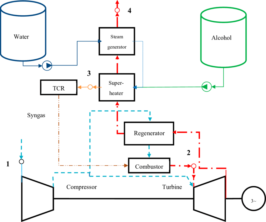
A biomass CHP (Combined Heat and Power) power plant is a sophisticated renewable energy facility designed to simultaneously generate electricity and useful thermal energy from a variety of biomass feedstocks, providing a highly efficient and sustainable energy solution. These plants utilize woody biomass, agricultural residues, energy crops, municipal green waste, and select industrial organic residues, each with distinct moisture content, calorific value, density, particle size, and ash composition. Effective operation requires extensive preprocessing, including drying, shredding, grinding, screening, and sometimes pelletizing or briquetting, to ensure uniform feedstock quality and consistent combustion or gasification performance. By standardizing the feedstock, the plant can optimize energy conversion efficiency, reduce operational disruptions, facilitate storage and transport, and achieve predictable electricity and heat output. Advanced biomass CHP plants are designed to handle variable feedstocks, balancing moisture content and calorific value to ensure stable and efficient energy generation while minimizing emissions and operational risks.
At the core of a biomass CHP power plant is the energy conversion system, which often consists of a biomass boiler, gasifier, or torrefaction unit coupled with a steam turbine, internal combustion engine, or gas turbine. In a combustion-based system, preprocessed biomass is fed into a high-efficiency boiler or furnace, where it is burned under controlled conditions to generate high-pressure steam. This steam drives a turbine connected to an electricity generator, producing renewable electricity. The residual thermal energy from flue gases, steam extraction, or condensers is captured and redirected for industrial processes, district heating, greenhouse heating, or domestic hot water, achieving high overall energy efficiency that can reach 80–90% when both electricity and heat are utilized effectively. In gasification-based CHP systems, biomass is converted into syngas, a mixture of hydrogen, carbon monoxide, and methane, which can be combusted in a gas engine or turbine to generate electricity while capturing waste heat for CHP applications. This dual-output approach maximizes the energy extracted from the biomass, reduces fuel consumption per unit of energy output, and provides flexible energy solutions for both local and industrial energy demands.
Advanced operational control and automation are critical for the efficiency and reliability of biomass CHP plants. Continuous monitoring of feedstock input, combustion temperature, residence time, steam pressure, turbine operation, and flue gas composition allows operators to optimize process parameters, ensure stable energy production, and maintain compliance with environmental regulations. Sophisticated control systems utilize predictive algorithms and adaptive feedback to adjust fuel feed rates, airflow, combustion intensity, and steam extraction in real time, preventing issues such as slagging, fouling, incomplete combustion, or thermal imbalances. Water treatment systems ensure that feedwater and steam quality meet strict standards, preventing corrosion, scaling, and efficiency losses in boilers, turbines, and heat exchangers, which is particularly critical for long-term plant reliability and continuous operation. Safety systems, including overpressure protection, automatic shutdowns, alarms, and redundancy measures, safeguard both equipment and personnel from potential hazards such as dust explosions, over-temperature events, or blockages in fuel feeding systems.
Residue and by-product management is a key aspect of biomass CHP plant operation. Combustion produces ash, which is collected using hoppers, conveyors, silos, and pneumatic transport systems, and can be repurposed as a soil amendment, fertilizer, or construction material, supporting sustainability and circular economy principles. Volatile organic compounds released during torrefaction or combustion can be captured and utilized as process heat, reducing reliance on external fuels and improving overall plant efficiency. Gasification produces char or tar by-products, which may be recycled, combusted, or used as soil conditioners. In addition, moisture extracted from feedstock or process condensate can be reused within the system, contributing to water efficiency and reducing environmental discharge. Proper management of residues ensures continuous operation, reduces maintenance requirements, and enhances the environmental and economic sustainability of the facility.
Emissions control in biomass CHP plants benefits from the predictable combustion characteristics of preprocessed biomass and advanced flue gas treatment technologies. Particulate matter, nitrogen oxides, sulfur oxides, and volatile organic compounds are managed through cyclones, baghouse filters, electrostatic precipitators, wet scrubbers, or catalytic systems as required. Combustion optimization strategies, such as staged combustion, flue gas recirculation, and precise temperature management, further reduce emissions at the source. When torrefied or pelletized biomass is used, the lower moisture content and higher calorific value reduce smoke, particulate emissions, and fouling of heat exchangers, allowing cleaner, more efficient, and reliable operation. Co-firing biomass with fossil fuels in CHP plants additionally decreases net carbon dioxide emissions, supporting climate change mitigation objectives and providing a transitional pathway toward fully renewable energy systems while maintaining energy security and consistent electricity supply.
Advanced biomass CHP power plants provide significant advantages in operational flexibility, energy efficiency, and environmental performance. By producing electricity and heat simultaneously, they extract maximum energy from biomass feedstocks, achieving efficiency levels far superior to electricity-only generation systems. Their ability to handle a wide range of feedstock types ensures resilience to seasonal or regional variations in biomass availability, while modular and scalable plant designs allow operators to adjust capacity and outputs according to energy demand or feedstock supply. Integration of high-efficiency boilers, turbines, engines, heat exchangers, and emissions control systems ensures optimal energy utilization, environmental compliance, and sustainable operation. Through advanced control systems, residue management, heat recovery, and operational optimization, biomass CHP plants can deliver reliable electricity and useful heat to industrial facilities, municipal grids, district heating networks, or greenhouse operations, while reducing greenhouse gas emissions, promoting renewable energy adoption, and supporting a circular economy. The combination of electricity generation and heat utilization, coupled with sustainable residue management and emission control, positions biomass CHP power plants as a vital technology for decentralized, low-carbon, and efficient renewable energy production worldwide.
A biomass CHP (Combined Heat and Power) power plant is a highly integrated renewable energy facility that efficiently converts a wide range of biomass feedstocks into both electricity and thermal energy, achieving significantly higher overall efficiency compared to conventional electricity-only biomass plants. These facilities are designed to utilize woody biomass, agricultural residues such as straw, corn stover, husks, energy crops, municipal green waste, and select industrial organic residues, each with unique characteristics including moisture content, calorific value, particle size, density, and ash composition. Because of the variability in feedstock quality, advanced preprocessing systems are essential, performing drying, shredding, grinding, screening, and sometimes pelletizing or briquetting to ensure uniformity in particle size and moisture content. This preprocessing not only facilitates smoother feeding into boilers, furnaces, or gasifiers but also enhances combustion or gasification efficiency, reduces operational disruptions, and enables more predictable electricity and heat production. By standardizing the biomass feedstock, the plant can maintain optimal thermal performance and reduce emissions, while improving transport, storage, and handling logistics.
At the core of a biomass CHP power plant is a thermal conversion system that often combines high-efficiency boilers or furnaces with steam turbines, internal combustion engines, or gas turbines to produce electricity, while simultaneously capturing waste heat for heating or industrial processes. In direct combustion systems, biomass is burned under controlled conditions to generate high-pressure steam, which drives a turbine connected to a generator, producing renewable electricity. Heat from the steam extraction, condensers, or flue gases is captured through economizers, superheaters, and heat exchangers to supply district heating, industrial process heat, or greenhouse heating. In gasification-based CHP systems, biomass is converted into syngas consisting mainly of hydrogen, carbon monoxide, and methane, which is then combusted in a gas engine or turbine to generate electricity, with the residual thermal energy utilized for heating applications. The integration of both electricity and heat production maximizes energy utilization from biomass feedstocks, reduces fuel consumption per unit of energy, and increases the overall sustainability and economic viability of the plant. Torrefied or pelletized biomass is often used in these systems to improve fuel handling, calorific value, combustion stability, and storage life, further enhancing plant performance.
Operational control in biomass CHP plants is sophisticated, leveraging automated monitoring systems and digital control platforms to maintain stable and efficient operation. Continuous measurement of feedstock input, combustion temperature, steam pressure, turbine speed, gas composition, and emissions enables real-time adjustments to fuel feed rate, airflow, and combustion parameters. Predictive algorithms and adaptive control allow for optimization of thermal efficiency, prevention of slagging, fouling, incomplete combustion, or overtemperature conditions, and reliable coordination between electricity generation and heat supply. Water treatment and steam quality control are critical to prevent scaling, corrosion, and efficiency loss in boilers, turbines, and heat exchangers, ensuring long-term reliability. Safety systems, including overpressure protection, alarms, automatic shutdowns, and redundant controls, protect both personnel and equipment from potential hazards such as dust explosions, fuel blockages, or high-temperature events.
Residue and by-product management is an integral component of biomass CHP operation. Solid residues such as ash, char, or biochar are collected using silos, hoppers, conveyors, or pneumatic transport systems, and can be repurposed as soil amendments, fertilizers, construction materials, or secondary fuels, promoting circular resource use. Volatile organic compounds and tars released during torrefaction, pyrolysis, or gasification can be captured and combusted to supply internal process heat, reducing dependence on external fuel. Moisture extracted from feedstock or condensate recovery can be reused within the system, improving water efficiency. Effective management of residues ensures continuous operation, minimizes maintenance, and enhances both the environmental and economic sustainability of the plant.
Emissions control in biomass CHP plants is enhanced by the predictable combustion characteristics of preprocessed biomass and the application of advanced flue gas treatment technologies. Multi-stage systems including cyclones, baghouse filters, electrostatic precipitators, wet scrubbers, and catalytic converters capture particulate matter, nitrogen oxides, sulfur oxides, and volatile organic compounds. Operational optimization such as staged combustion, flue gas recirculation, and precise temperature management reduces pollutant formation at the source. The use of torrefied or pelletized biomass, with lower moisture and higher energy content, results in cleaner combustion, reduced smoke and particulate emissions, and more stable thermal performance. Co-firing with fossil fuels further lowers net carbon dioxide emissions, supporting climate change mitigation while maintaining a stable energy supply.
Advanced biomass CHP power plants provide substantial environmental, operational, and economic advantages. By producing electricity and useful heat simultaneously, they achieve high overall energy efficiency, often exceeding 80–90% when heat is fully utilized. The flexibility to process a wide variety of feedstocks ensures resilience to seasonal or regional variability in biomass supply, while modular and scalable designs allow operators to adjust capacity and output to match energy demand and feedstock availability. Integration of high-efficiency boilers, turbines, engines, heat recovery systems, and emission control technologies maximizes energy utilization, reduces fuel consumption, and ensures environmental compliance. Through sophisticated control systems, optimized heat integration, and effective residue management, biomass CHP plants can reliably supply renewable electricity and thermal energy to industrial facilities, district heating networks, or greenhouse operations. By transforming diverse biomass feedstocks into high-value energy with minimal emissions and sustainable residue utilization, these plants support a low-carbon energy transition, enhance energy security, and contribute to circular economy principles, providing decentralized, efficient, and reliable energy solutions on a local, regional, or industrial scale.
A biomass CHP power plant is a highly efficient, integrated energy facility that simultaneously produces electricity and usable heat from a wide variety of biomass feedstocks, delivering substantial improvements in overall energy utilization compared to conventional electricity-only systems. These plants are engineered to process a diverse range of materials including woody biomass, forestry residues, agricultural by-products such as straw, corn stover, and husks, energy crops, municipal green waste, and selected industrial organic residues. Each type of feedstock presents unique challenges due to variations in moisture content, calorific value, particle size, density, and ash composition, making preprocessing essential. Advanced preprocessing systems employ drying, shredding, grinding, screening, and sometimes pelletizing or briquetting to create a uniform, consistent feedstock, enabling smoother feeding into boilers, furnaces, or gasifiers and ensuring predictable combustion or gasification performance. This standardization improves not only operational reliability but also energy efficiency, emissions control, and heat and power output, while facilitating transport, storage, and handling logistics.
The core of a biomass CHP plant revolves around the energy conversion system, which may include high-efficiency biomass boilers, gasifiers, torrefaction units, steam turbines, internal combustion engines, or gas turbines. In combustion-based systems, preprocessed biomass is burned under carefully controlled conditions to generate high-pressure steam, which drives a turbine to produce electricity. Heat generated in the process, whether from flue gases, steam extraction, or condensers, is captured through economizers, superheaters, reheaters, and heat exchangers for use in industrial processes, district heating, greenhouse heating, or other thermal applications. Gasification-based CHP systems convert biomass into a syngas composed mainly of hydrogen, carbon monoxide, and methane, which is combusted in a gas engine or turbine to produce electricity while capturing residual thermal energy for heating applications. Torrefied or pelletized biomass is often employed to improve fuel handling, energy density, combustion stability, and storage longevity, thereby enhancing plant efficiency, reducing emissions, and allowing for consistent operation under varying feedstock conditions. The dual production of electricity and heat enables biomass CHP plants to maximize energy recovery, reduce overall fuel consumption, and provide a flexible and reliable energy supply for local or industrial demands.
Operational management and automation are critical for optimizing efficiency and ensuring safe, continuous operation of biomass CHP plants. Advanced control systems monitor key parameters in real time, including feedstock feed rates, combustion or gasification temperature, residence time, steam pressure, turbine performance, and flue gas composition, enabling dynamic adjustment of fuel feed, airflow, and thermal management. Predictive algorithms and adaptive controls help prevent operational issues such as slagging, fouling, incomplete combustion, or overtemperature events while ensuring coordinated electricity and heat output. Water treatment and steam quality management are crucial for maintaining optimal boiler and turbine performance, preventing scaling, corrosion, and efficiency loss. Safety systems, including automatic shutdowns, overpressure protection, alarms, and redundancies, safeguard personnel and equipment from hazards such as dust explosions, high-temperature events, or fuel blockages, which are especially important in facilities handling variable biomass feedstocks.
Residue and by-product management is integral to the efficiency and sustainability of biomass CHP plants. Combustion produces ash, char, or biochar, which can be collected and repurposed as soil amendments, fertilizers, construction materials, or secondary fuels, promoting circular resource use and adding economic value. Volatile organic compounds released during torrefaction, pyrolysis, or gasification can be captured and combusted to supply internal process heat, reducing reliance on external fuels. Moisture recovered from feedstock or condensate can be reused within the system, improving water efficiency and reducing environmental discharge. Efficient collection and transport of residues through silos, hoppers, conveyors, and pneumatic systems ensures continuous operation, reduces maintenance requirements, and minimizes environmental impact, all of which contribute to the overall operational sustainability and economic viability of the plant.
Emissions control in biomass CHP plants is enhanced by the consistent combustion characteristics of preprocessed biomass and the application of advanced flue gas cleaning systems. Multi-stage treatment technologies such as cyclones, baghouse filters, electrostatic precipitators, wet scrubbers, and catalytic converters capture particulate matter, nitrogen oxides, sulfur oxides, and volatile organic compounds. Operational strategies like staged combustion, flue gas recirculation, and precise temperature management further minimize pollutant formation at the source. Use of torrefied or pelletized biomass with lower moisture content and higher calorific value improves combustion efficiency and reduces smoke, particulate emissions, and fouling of heat exchangers. Co-firing with fossil fuels can further reduce net carbon dioxide emissions, supporting climate change mitigation while maintaining consistent electricity generation and heat supply. These emissions control strategies, combined with optimized operational management, ensure compliance with environmental regulations and contribute to the long-term sustainability of the facility.
Advanced biomass CHP power plants offer substantial benefits in efficiency, environmental performance, and operational flexibility. By producing electricity and useful thermal energy simultaneously, they achieve high overall energy utilization, often exceeding 80–90% when heat is fully utilized. The ability to process a wide range of feedstocks ensures resilience to seasonal and regional variability, while modular and scalable plant designs allow operators to adjust capacity and energy outputs according to demand and available biomass. Integration of high-efficiency boilers, turbines, engines, heat recovery systems, and emissions control technologies ensures optimal energy extraction, reduced fuel consumption, and compliance with environmental standards. Through sophisticated control systems, optimized heat integration, and effective residue management, biomass CHP plants provide reliable, decentralized renewable energy for industrial facilities, municipal grids, district heating networks, and greenhouse operations. By transforming diverse biomass resources into electricity, heat, and value-added by-products with minimal emissions, these facilities support a low-carbon, circular economy, enhance energy security, and contribute to sustainable, decentralized energy production at a local, regional, and industrial scale.
A biomass CHP (Combined Heat and Power) power plant is a sophisticated renewable energy facility that transforms diverse biomass feedstocks into both electricity and thermal energy, achieving significantly higher overall efficiency than conventional electricity-only systems and providing an integrated solution for energy, heat, and environmental sustainability. These plants are engineered to process a broad spectrum of biomass materials, including woody biomass, forestry residues, agricultural by-products like straw, corn stover, and husks, energy crops, municipal green waste, and selected industrial organic residues, each of which has unique properties such as moisture content, particle size, calorific value, density, and ash composition. To ensure consistent and reliable operation, advanced preprocessing systems are employed to dry, shred, grind, screen, and, in many cases, pelletize or briquette the biomass. These steps standardize the feedstock, improving its combustion or gasification characteristics, enhancing handling, transport, and storage, and enabling predictable thermal and electrical output. By providing a uniform fuel input, preprocessing maximizes energy conversion efficiency, reduces operational disruptions, limits emissions, and supports the long-term reliability of the plant’s thermal and electrical systems.
At the heart of a biomass CHP plant lies the energy conversion system, which typically combines high-efficiency biomass boilers, gasifiers, or torrefaction units with steam turbines, gas turbines, or internal combustion engines. In combustion-based systems, preprocessed biomass is burned in a controlled furnace or boiler to generate high-pressure steam, which drives turbines connected to electrical generators. The heat extracted from steam condensers, flue gases, or steam extraction loops is captured and utilized for industrial processes, district heating networks, greenhouse heating, or other thermal applications, ensuring that nearly all available energy is recovered. In gasification-based systems, biomass is thermochemically converted into syngas composed primarily of hydrogen, carbon monoxide, and methane, which is combusted in engines or turbines to generate electricity, while waste heat is captured for CHP applications. Torrefied or pelletized biomass may be used to enhance energy density, combustion stability, and storage life, reducing operational variability and increasing thermal efficiency. The dual production of electricity and heat enables biomass CHP plants to maximize energy recovery, lower fuel consumption per unit of energy, and provide flexible, reliable energy output to meet local or industrial demands.
Operational management in biomass CHP plants is highly sophisticated due to the complexity of handling variable feedstocks and the dual requirements of electricity and heat generation. Advanced digital monitoring and automation systems continuously track feedstock feed rates, reactor temperatures, residence times, steam pressure, turbine or engine performance, flue gas composition, and emissions, enabling dynamic adjustments to fuel feed, airflow, combustion intensity, and heat extraction. Predictive algorithms and adaptive control systems prevent operational issues such as slagging, fouling, incomplete combustion, or overtemperature events, while ensuring stable and optimized energy output. Maintaining proper water and steam quality is essential to prevent scaling, corrosion, and efficiency losses in boilers, turbines, and heat exchangers. Integrated safety systems, including overpressure protection, automatic shutdowns, alarms, and redundant controls, safeguard both personnel and equipment against potential hazards, such as dust explosions, fuel blockages, or high-temperature incidents, which are particularly important when handling heterogeneous biomass feedstocks.
Residue and by-product management is a critical component of biomass CHP plant operation. Solid residues such as ash, char, and biochar are collected using silos, hoppers, conveyors, or pneumatic transport systems and can be repurposed as soil amendments, fertilizers, construction materials, or secondary fuels, supporting circular economy practices and generating additional revenue streams. Volatile organic compounds released during torrefaction, pyrolysis, or gasification can be captured and combusted to supply internal process heat, reducing dependence on external energy sources. Moisture recovered from feedstock or condensate streams may be reused within the process, enhancing water efficiency and reducing wastewater discharge. Efficient residue handling ensures continuous operation, minimizes maintenance needs, and contributes to the environmental and economic sustainability of the plant, while enabling the facility to achieve a near-zero waste profile.
Emissions control in biomass CHP plants is enhanced through the consistent combustion properties of preprocessed biomass and advanced multi-stage flue gas treatment technologies. Systems such as cyclones, baghouse filters, electrostatic precipitators, wet scrubbers, and catalytic converters remove particulate matter, nitrogen oxides, sulfur oxides, and volatile organic compounds, ensuring compliance with strict air quality regulations. Operational strategies like staged combustion, flue gas recirculation, and precise thermal management reduce pollutant formation at the source. Utilizing torrefied or pelletized biomass with lower moisture content and higher calorific value further improves combustion efficiency, reduces smoke and particulate emissions, and stabilizes heat and electricity output. Co-firing biomass with fossil fuels additionally lowers net carbon dioxide emissions, providing a transitional pathway toward fully renewable energy systems while maintaining reliable electricity and heat generation.
Advanced biomass CHP power plants deliver significant benefits in operational flexibility, energy efficiency, and environmental performance. By producing electricity and useful thermal energy simultaneously, they achieve overall energy utilization often exceeding 80–90% when heat is fully harnessed. Their ability to process a wide array of feedstocks ensures resilience to seasonal or regional variability in biomass availability, while modular and scalable designs allow operators to adjust capacity, conversion methods, and output to match energy demand or feedstock supply. Integration of high-efficiency boilers, turbines, engines, heat recovery systems, and emission control technologies maximizes energy extraction, minimizes fuel consumption, and ensures compliance with environmental standards. With sophisticated digital controls, optimized heat integration, and effective residue management, biomass CHP plants provide decentralized, renewable energy to industrial facilities, district heating networks, municipal grids, and greenhouse operations. By converting diverse biomass resources into electricity, heat, and high-value by-products with minimal emissions, these plants support low-carbon, circular economy principles, enhance energy security, and provide reliable, sustainable energy solutions at industrial, regional, and local scales.
Biomass Fermentation Power Plant

A biomass fermentation power plant is a specialized renewable energy facility designed to convert organic biomass materials into biogas, primarily composed of methane and carbon dioxide, through controlled microbial fermentation processes, thereby generating both electricity and heat while providing a sustainable alternative to fossil fuels. These plants are capable of processing a wide variety of biomass feedstocks including agricultural residues such as crop stalks, husks, and fruit and vegetable waste, animal manure, energy crops like maize silage or grasses, municipal organic waste, food processing residues, and selected industrial organic by-products. Each feedstock has unique characteristics, including moisture content, carbohydrate, protein, and lignocellulosic composition, which significantly influence the fermentation rate, biogas yield, and nutrient content of the resulting digestate. To ensure consistent operation and maximize biogas production, feedstocks are subjected to preprocessing, which may include shredding, grinding, homogenization, drying, or partial hydrolysis to improve microbial accessibility and facilitate uniform digestion in the bioreactors.
At the core of a biomass fermentation plant are the anaerobic digesters, which provide controlled environments for microbial communities to break down complex organic matter in the absence of oxygen. These digesters are designed to maintain optimal temperature, pH, nutrient balance, and mixing conditions to enhance microbial activity and maximize methane yield. Mesophilic and thermophilic digestion regimes are commonly employed, with thermophilic processes operating at higher temperatures for faster digestion and improved pathogen reduction, while mesophilic systems offer greater operational stability and energy efficiency. The residence time, typically ranging from several days to weeks depending on feedstock characteristics and digester design, ensures complete degradation of organic matter while minimizing the production of inhibitory by-products. Advanced designs incorporate continuous feeding systems, automated mixing, and gas-tight sealing to maintain consistent fermentation conditions and prevent the loss of valuable biogas.
The biogas produced through fermentation is collected and processed to remove impurities such as hydrogen sulfide, moisture, siloxanes, and particulate matter, ensuring safe and efficient combustion in combined heat and power (CHP) units or gas engines. These engines or turbines convert the chemical energy of biogas into electricity while simultaneously capturing waste heat for district heating, industrial processes, or greenhouse applications, significantly enhancing overall energy utilization. Biogas can also be upgraded through CO₂ removal and gas scrubbing to produce biomethane suitable for injection into natural gas grids or use as a vehicle fuel, further expanding the versatility of biomass fermentation energy systems. Heat management within the plant is critical, as a portion of the recovered thermal energy is often recycled to maintain optimal digester temperatures, improve reaction kinetics, and stabilize microbial populations, particularly in thermophilic systems.
Operational control and automation are essential for maintaining efficiency and safety in biomass fermentation plants. Real-time monitoring of feedstock input, digester temperature, pH, mixing intensity, gas production, methane concentration, and nutrient balance allows for dynamic adjustment of process parameters to prevent process upsets, ensure maximum biogas yield, and maintain stable energy output. Advanced control algorithms and predictive modeling enable operators to optimize feedstock blending, regulate digestion rates, and maintain microbial health, while integrated safety systems mitigate risks such as overpressure, gas leaks, and potential contamination. Water treatment systems manage digestate moisture and nutrient content, ensuring the effluent is suitable for agricultural application or further processing while preventing environmental pollution.
Residue and by-product management is a critical aspect of biomass fermentation plants. The digestate produced after anaerobic digestion is rich in nutrients such as nitrogen, phosphorus, and potassium, making it a valuable soil amendment or fertilizer. Solid and liquid fractions of the digestate can be separated and processed according to agricultural requirements, while excess water is treated and reused or safely discharged. Efficient handling of feedstock residues, digestate, and non-fermentable solids ensures continuous plant operation, minimizes maintenance requirements, and contributes to the environmental and economic sustainability of the facility. In addition, residual biomass that cannot be digested can be redirected to other energy recovery processes such as combustion, gasification, or torrefaction, enhancing overall energy recovery from the feedstock.
Emissions control in biomass fermentation power plants is relatively straightforward compared to combustion-based systems, as anaerobic digestion produces minimal particulate matter, sulfur oxides, or nitrogen oxides. Methane emissions are carefully contained and captured to prevent greenhouse gas release, while biogas combustion in CHP units produces primarily CO₂ and water vapor, contributing to a lower carbon footprint. Odor management and proper handling of feedstock and digestate are crucial to prevent nuisance emissions, and advanced sealing, ventilation, and gas scrubbing systems are implemented to maintain safe and environmentally compliant operation. The integration of fermentation with CHP and potential biomethane upgrading ensures that the energy recovered from biomass is maximized while minimizing environmental impacts and supporting sustainable energy production goals.
Biomass fermentation power plants provide significant operational, environmental, and economic benefits by transforming underutilized organic materials into high-value renewable energy, while producing nutrient-rich by-products for agricultural or industrial use. By combining anaerobic digestion with CHP or biomethane production, these facilities achieve high energy utilization, reduce reliance on fossil fuels, mitigate greenhouse gas emissions, and contribute to a circular economy through sustainable waste management and nutrient recycling. The modularity and scalability of fermentation systems allow plants to adapt to available feedstock quantities, energy demand, and regional regulatory frameworks, making them suitable for decentralized energy production in rural, industrial, and municipal settings. With sophisticated operational controls, efficient residue handling, optimized biogas utilization, and low environmental impact, biomass fermentation power plants are a reliable and sustainable technology for renewable energy generation, supporting climate goals, energy security, and resource-efficient waste management at local, regional, and industrial scales.
A biomass fermentation power plant is a highly integrated renewable energy facility designed to convert organic biomass materials into biogas through controlled anaerobic microbial processes, generating both electricity and heat while providing sustainable waste management and a low-carbon energy solution. These plants can process a broad range of biomass feedstocks, including agricultural residues such as corn stover, straw, fruit and vegetable waste, animal manure, energy crops like maize silage and grasses, municipal organic waste, food processing residues, and selected industrial organic by-products. Each type of feedstock has unique characteristics, such as moisture content, carbon-to-nitrogen ratio, lignocellulosic composition, and nutrient content, which directly influence fermentation efficiency, methane yield, and the quality of digestate. To ensure consistent and efficient operation, advanced preprocessing systems are employed to shred, grind, homogenize, and sometimes partially hydrolyze the biomass, increasing microbial accessibility and creating a uniform feedstock for optimal digestion performance. These preprocessing steps also facilitate feeding, transport, storage, and handling, while improving the stability of biogas production and the predictability of energy output.
At the core of a biomass fermentation plant are the anaerobic digesters, which provide controlled, oxygen-free environments where microbial consortia break down complex organic matter into biogas. Digesters are designed to maintain specific temperature regimes—mesophilic or thermophilic—to optimize microbial activity, with thermophilic systems offering faster digestion and pathogen reduction, while mesophilic systems provide operational stability and lower energy requirements. Residence time, which can range from several days to weeks depending on feedstock type and digester design, ensures complete degradation of organic matter and maximizes methane production while minimizing inhibitory by-products. Advanced digesters often incorporate continuous or semi-continuous feeding systems, automated mixing, and gas-tight seals to maintain consistent fermentation conditions and prevent gas losses. Control of pH, nutrient balance, and microbial health is critical, as deviations can reduce biogas yield or destabilize the digestion process. Thermal management is also important, as recovered heat from biogas combustion can be recycled to maintain optimal digester temperatures, particularly in thermophilic processes.
The biogas produced through fermentation is collected and conditioned to remove moisture, hydrogen sulfide, siloxanes, and particulates, ensuring safe and efficient utilization in combined heat and power (CHP) units or engines. In CHP configurations, the chemical energy of biogas is converted into electricity while simultaneously capturing waste heat for district heating, industrial processes, or greenhouse applications, significantly enhancing overall energy utilization. Biogas can also be upgraded to biomethane by removing carbon dioxide and other impurities, allowing it to be injected into natural gas grids or used as a renewable transport fuel. This versatility increases the economic viability of fermentation plants, enabling them to supply electricity, heat, and biomethane depending on demand, feedstock availability, and market conditions. Effective integration of energy recovery with biogas production ensures high efficiency and allows operators to maintain continuous and flexible energy output.
Operational management in biomass fermentation plants relies on sophisticated digital monitoring and automation systems that track feedstock flow, digester temperature, pH, mixing intensity, biogas production rate, methane content, and nutrient balance in real time. These systems allow dynamic adjustments to feedstock input, mixing regimes, temperature control, and nutrient supplementation, preventing process upsets, maintaining stable biogas production, and ensuring optimal energy recovery. Advanced predictive algorithms support feedstock blending strategies to maximize methane yield and maintain microbial health, while integrated safety systems prevent hazards such as overpressure, gas leaks, or contamination events. Water treatment and digestate management are essential to prevent corrosion, scaling, and environmental pollution, ensuring that effluents are suitable for reuse as fertilizers or soil amendments. Effective operational control allows biomass fermentation plants to achieve high efficiency, stable performance, and long-term reliability despite the inherent variability of organic feedstocks.
Residue and by-product management is an essential aspect of biomass fermentation plant operation. Digestate, the residual material left after anaerobic digestion, is nutrient-rich and can be separated into solid and liquid fractions for use as soil amendments or fertilizers, closing nutrient loops and supporting circular economy principles. Non-fermentable solids can be redirected to thermal energy recovery processes such as combustion, gasification, or torrefaction, ensuring maximum energy extraction from the biomass feedstock. Moisture recovery, residue handling systems, and efficient transport mechanisms including silos, conveyors, hoppers, and pneumatic pipelines facilitate continuous plant operation, reduce maintenance requirements, and minimize environmental impacts. By effectively managing residues, biomass fermentation plants not only recover energy but also produce valuable co-products, enhancing economic returns and promoting sustainable resource utilization.
Emissions control in biomass fermentation plants is comparatively straightforward, as anaerobic digestion produces minimal particulate matter, sulfur oxides, and nitrogen oxides. Methane emissions are carefully contained to prevent greenhouse gas release, while the combustion of biogas in CHP units produces primarily carbon dioxide and water vapor, significantly reducing the carbon footprint compared to fossil fuels. Odor management and proper handling of feedstock and digestate are critical, and advanced sealing, ventilation, and gas scrubbing systems are implemented to maintain environmental compliance. By combining fermentation with CHP, heat recovery, and potential biomethane upgrading, these plants maximize energy recovery, reduce environmental impacts, and contribute to sustainable energy production while providing decentralized, low-carbon energy for industrial, municipal, and agricultural applications.
Biomass fermentation power plants offer substantial operational, environmental, and economic benefits by converting underutilized organic materials into renewable energy while producing nutrient-rich by-products for agriculture or industry. Their modular and scalable designs allow adaptation to feedstock availability, energy demand, and local regulatory requirements, making them suitable for decentralized energy production in rural, industrial, or municipal contexts. Advanced operational control, optimized digester performance, biogas upgrading, heat integration, and residue management enable high energy recovery efficiency, low environmental impact, and stable electricity and heat supply. By transforming diverse organic biomass into electricity, heat, and biomethane with minimal emissions and sustainable by-product utilization, biomass fermentation plants support circular economy principles, climate change mitigation, energy security, and efficient waste management, providing reliable and sustainable renewable energy solutions across multiple sectors and geographic regions.
A biomass fermentation power plant is a highly integrated renewable energy facility that harnesses the biochemical potential of organic biomass to produce biogas, a methane-rich fuel, which can then be converted into electricity, heat, or upgraded into biomethane for further applications, creating a highly efficient and sustainable energy system. These plants are designed to process a wide variety of feedstocks including agricultural residues such as corn stover, straw, husks, and fruit and vegetable waste, animal manure, energy crops like maize silage or grasses, municipal organic waste, food processing by-products, and selected industrial organic residues. Each type of biomass presents unique challenges due to variations in moisture content, carbohydrate, protein, and lignocellulosic composition, which affect the efficiency of microbial fermentation and methane production. To optimize the digestion process, feedstocks undergo extensive preprocessing, which may include shredding, grinding, homogenization, drying, partial hydrolysis, or even enzymatic treatment to improve accessibility for anaerobic microbes and create a uniform feedstock capable of delivering stable and high biogas yields. These preprocessing measures also enhance handling, feeding, storage, and transport logistics, contributing to consistent operational performance and predictable energy output.
At the core of a biomass fermentation plant are anaerobic digesters, which provide controlled oxygen-free environments for microbial communities to break down complex organic matter into methane and carbon dioxide. Digesters are designed to maintain optimal conditions for microbial activity, including temperature, pH, nutrient balance, and mixing intensity, with mesophilic and thermophilic regimes commonly employed. Thermophilic digestion offers faster reaction rates, pathogen reduction, and improved biogas yield, whereas mesophilic digestion provides greater operational stability and lower energy requirements. Residence time in the digesters is carefully controlled, ranging from several days to weeks depending on feedstock characteristics and digester design, ensuring complete breakdown of organic matter while minimizing inhibitory compounds. Advanced digester systems often include continuous or semi-continuous feeding, automated mixing, and gas-tight sealing to maintain uniform fermentation conditions and prevent biogas leakage, while heat recovered from CHP operations or combustion of part of the biogas is recirculated to maintain optimal digestion temperatures and enhance microbial performance.
The biogas generated through fermentation is collected and processed to remove moisture, hydrogen sulfide, siloxanes, and particulate matter, ensuring safe and efficient use in combined heat and power (CHP) units or internal combustion engines. These systems convert the chemical energy of the biogas into electricity while simultaneously capturing waste heat for district heating, industrial processes, or greenhouse applications, greatly increasing overall energy efficiency. Biogas can also be upgraded to biomethane by removing carbon dioxide and other impurities, enabling injection into natural gas grids or use as renewable transport fuel, thereby expanding the versatility and economic potential of biomass fermentation plants. Effective thermal management is crucial to optimize digestion kinetics, maintain microbial stability, and support continuous CHP operation, with recovered heat used to preheat feedstocks, maintain digester temperature, or supply external thermal loads.
Operational control in biomass fermentation plants relies on advanced digital monitoring and automation systems that continuously track feedstock feed rates, digester temperature, pH, mixing intensity, gas production rates, methane concentration, and nutrient balance. These systems allow real-time adjustments to process parameters to prevent upsets, maximize methane yield, and ensure stable energy production. Predictive control algorithms facilitate feedstock blending strategies to maintain microbial health and optimize biogas quality, while integrated safety systems protect against overpressure, gas leaks, or contamination events. Water treatment and digestate management are critical, as effluent streams must be treated or conditioned for agricultural application while preventing scaling, corrosion, or environmental pollution, ensuring long-term plant reliability and sustainable operation.
Residue and by-product management is an essential component of biomass fermentation power plants. The digestate produced after anaerobic digestion is nutrient-rich and can be separated into solid and liquid fractions, with solids often used as soil amendments or fertilizers and liquids utilized as irrigation nutrients or further processed to recover nutrients. Non-fermentable solids can be redirected to combustion or gasification systems, further enhancing overall energy recovery from the biomass feedstock. Efficient residue handling, including the use of silos, hoppers, conveyors, and pneumatic transport systems, ensures continuous plant operation, reduces maintenance demands, and minimizes environmental impacts. By integrating residue utilization with energy recovery, biomass fermentation plants achieve both economic and environmental sustainability while supporting circular economy principles.
Emissions control in biomass fermentation plants is comparatively straightforward, as anaerobic digestion produces minimal particulate matter, nitrogen oxides, or sulfur oxides. Methane and other gases are carefully captured and utilized to prevent greenhouse gas emissions, while biogas combustion in CHP units primarily generates carbon dioxide and water vapor, offering a significantly lower carbon footprint than fossil fuel alternatives. Odor management is critical, and advanced sealing, ventilation, and gas treatment systems ensure that feedstock handling, fermentation, and digestate management do not produce nuisance odors. By combining anaerobic digestion with CHP, heat recovery, and potential biomethane upgrading, biomass fermentation plants maximize energy utilization, reduce environmental impact, and contribute to sustainable, decentralized energy production for industrial, municipal, and agricultural applications.
Biomass fermentation power plants provide substantial operational, environmental, and economic benefits by transforming organic waste and underutilized biomass into renewable energy while producing nutrient-rich by-products suitable for agriculture or industrial use. The modular and scalable nature of these plants allows adaptation to variations in feedstock availability, energy demand, and local regulatory requirements, making them suitable for rural, industrial, or municipal decentralized energy generation. Advanced process control, optimized digester performance, biogas upgrading, heat recovery, and residue management enable high energy efficiency, stable electricity and heat supply, and low environmental impact. By converting diverse biomass resources into electricity, thermal energy, and biomethane with minimal emissions and sustainable by-product utilization, biomass fermentation plants support circular economy principles, climate change mitigation, energy security, and efficient waste management, providing a reliable and sustainable renewable energy solution at local, regional, and industrial scales.
A biomass fermentation power plant represents an advanced form of renewable energy facility that exploits the biochemical potential of organic materials through anaerobic digestion to generate biogas, which can be utilized for electricity, heat, or upgraded to biomethane, creating a versatile and sustainable energy system. These plants are designed to handle a wide array of biomass feedstocks, including agricultural residues such as crop stalks, corn stover, husks, straw, and fruit and vegetable waste, animal manure, energy crops like maize silage and grasses, municipal green waste, food processing by-products, and selected industrial organic residues. Each feedstock carries unique properties such as moisture content, carbon-to-nitrogen ratio, lignocellulosic composition, and nutrient content, which directly impact microbial fermentation efficiency, methane yield, and digestate quality. To maximize biogas production and ensure stable operation, feedstocks undergo extensive preprocessing, including shredding, grinding, homogenization, partial hydrolysis, and sometimes enzymatic or thermal treatment, creating a uniform feedstock with optimal particle size, moisture content, and digestibility. These preprocessing measures not only enhance microbial accessibility and biogas yield but also facilitate feeding, storage, transport, and operational consistency.
The core of a biomass fermentation plant is the anaerobic digester, a tightly controlled environment that allows microorganisms to decompose complex organic matter into methane and carbon dioxide under oxygen-free conditions. Digesters are engineered to maintain precise temperature ranges, with mesophilic and thermophilic systems commonly utilized. Thermophilic digestion operates at higher temperatures, accelerating reaction rates, improving pathogen reduction, and enhancing biogas yield, while mesophilic digestion provides operational stability and lower energy consumption. Digester design also accounts for mixing, pH control, nutrient balance, and residence time, which typically spans several days to weeks depending on feedstock type and characteristics, ensuring complete organic matter degradation while minimizing the formation of inhibitory compounds. Advanced digester systems often include continuous feeding mechanisms, automated mixing, heat integration, and gas-tight sealing to maintain consistent fermentation conditions and prevent methane loss. Recovered heat from biogas combustion or CHP operations is frequently recycled to maintain optimal digester temperatures, particularly in thermophilic regimes, boosting microbial activity and energy efficiency.
The biogas produced is collected and conditioned to remove moisture, hydrogen sulfide, siloxanes, and other impurities, ensuring safe and efficient combustion in combined heat and power (CHP) units or internal combustion engines. These systems convert the chemical energy of biogas into electricity while simultaneously capturing thermal energy for district heating, industrial processes, or greenhouse applications, maximizing overall energy recovery. Biogas can also be upgraded to biomethane by removing carbon dioxide and impurities, enabling injection into natural gas grids or use as a renewable transport fuel, thereby expanding the versatility and economic value of biomass fermentation plants. Heat management within the plant is critical, as a portion of the recovered thermal energy is often used to maintain digester temperature, preheat feedstock, or supply external thermal loads, ensuring optimal process kinetics and continuous CHP operation.
Operational control is essential for efficient and safe functioning of biomass fermentation plants. Digital monitoring and automation systems continuously track feedstock flow, digester temperature, pH, mixing intensity, gas production rate, methane concentration, and nutrient levels, allowing real-time adjustment of feed rates, thermal management, mixing, and supplementation to prevent process disturbances, optimize methane yield, and maintain stable energy output. Predictive modeling and advanced control algorithms support feedstock blending strategies to maintain microbial health and consistent biogas quality, while integrated safety measures protect against overpressure, gas leaks, and contamination events. Water treatment and digestate management are crucial, as effluent streams must meet agricultural or environmental standards, preventing scaling, corrosion, or pollution while ensuring nutrient recovery and plant reliability.
Residue and by-product handling is a key aspect of biomass fermentation plant operation. The digestate remaining after anaerobic digestion is rich in nutrients such as nitrogen, phosphorus, and potassium and can be separated into solid and liquid fractions for use as soil amendments, fertilizers, or irrigation nutrients. Non-fermentable solids can be redirected to thermal energy recovery systems such as combustion, gasification, or torrefaction, enhancing overall energy extraction from biomass feedstocks. Efficient residue handling, including the use of hoppers, silos, conveyors, and pneumatic systems, ensures continuous plant operation, minimizes maintenance, and reduces environmental impact. This integrated approach to residue management enables biomass fermentation plants to operate sustainably while generating valuable co-products and supporting circular economy principles.
Emissions control in biomass fermentation plants is comparatively straightforward compared to combustion-based systems, as anaerobic digestion produces minimal particulate matter, sulfur oxides, or nitrogen oxides. Methane emissions are carefully contained and captured, and biogas combustion primarily generates carbon dioxide and water vapor, significantly lowering the carbon footprint relative to fossil fuels. Odor management is critical, particularly during feedstock handling, digestion, and digestate storage, and advanced sealing, ventilation, and scrubbing systems are implemented to maintain environmental compliance and prevent nuisance issues. By integrating anaerobic digestion with CHP, heat recovery, and potential biomethane upgrading, biomass fermentation plants maximize energy recovery while reducing environmental impact, creating a decentralized, low-carbon energy solution suitable for industrial, municipal, and agricultural applications.
Biomass fermentation power plants offer significant operational, environmental, and economic advantages by transforming organic waste and underutilized biomass into renewable energy while producing nutrient-rich by-products for agriculture or industrial use. Their modular and scalable designs allow adaptation to available feedstock, regional energy demands, and local regulatory frameworks, making them suitable for decentralized energy production in rural, industrial, and municipal contexts. Advanced process control, optimized digester performance, biogas upgrading, heat integration, and residue management enable high energy efficiency, stable electricity and heat supply, and low environmental impact. By converting diverse biomass feedstocks into electricity, thermal energy, and biomethane with minimal emissions and sustainable by-product utilization, biomass fermentation plants support climate change mitigation, energy security, and circular economy principles, providing a reliable, sustainable, and flexible renewable energy solution at local, regional, and industrial scales.
Biomass Anaerobic Digestion Plant

A biomass anaerobic digestion (AD) plant is a highly specialized renewable energy facility that converts organic biomass materials into biogas through controlled microbial processes in an oxygen-free environment, producing a versatile energy source that can be utilized for electricity, heat, and biomethane applications while simultaneously generating nutrient-rich digestate for agricultural or industrial use. These plants are designed to process a wide variety of biomass feedstocks, including agricultural residues such as corn stover, straw, husks, fruit and vegetable waste, animal manure, energy crops such as maize silage and grasses, municipal organic waste, food processing by-products, and selected industrial organic residues. Each feedstock presents unique characteristics, including moisture content, carbon-to-nitrogen ratio, lignocellulosic composition, and nutrient content, all of which influence microbial activity, biogas yield, and the quality of the resulting digestate. To optimize the anaerobic digestion process, feedstocks are often subjected to preprocessing steps such as shredding, grinding, homogenization, drying, partial hydrolysis, or enzymatic treatment, which improve microbial accessibility, ensure uniform particle size, stabilize feedstock properties, and facilitate consistent digestion performance. These preprocessing measures also streamline feedstock handling, transport, and storage, allowing for uninterrupted operation and predictable energy output.
At the heart of a biomass anaerobic digestion plant are the digesters, which provide controlled, oxygen-free conditions where microbial consortia metabolize complex organic compounds into methane and carbon dioxide. Digesters are carefully engineered to maintain optimal temperatures, pH, nutrient balance, and mixing intensity, with mesophilic and thermophilic regimes commonly employed depending on feedstock type, desired reaction rates, and operational goals. Thermophilic digestion offers faster reaction kinetics, enhanced pathogen reduction, and higher methane yields, while mesophilic digestion provides operational stability, lower energy requirements, and more predictable performance under variable feedstock conditions. The residence time of biomass within the digesters, typically spanning several days to weeks, is precisely controlled to ensure complete organic matter breakdown while minimizing inhibitory by-products. Advanced AD systems incorporate continuous or semi-continuous feeding, automated mixing, heat integration, and gas-tight sealing to maintain uniform fermentation conditions and prevent biogas leakage. Recovered heat from biogas combustion or CHP operations is frequently recirculated to maintain optimal digester temperatures, enhancing microbial activity and overall energy efficiency.
The biogas produced in anaerobic digestion plants is collected and conditioned to remove impurities such as moisture, hydrogen sulfide, siloxanes, and particulates, ensuring safe and efficient utilization in combined heat and power (CHP) units, gas engines, or turbines. CHP systems convert the chemical energy of biogas into electricity while simultaneously capturing thermal energy for district heating, industrial processes, greenhouse operations, or other heat applications, significantly increasing the overall energy recovery from the biomass feedstock. Biogas can also be upgraded to biomethane through CO₂ removal and scrubbing processes, enabling injection into natural gas grids or use as a renewable transport fuel, thereby extending the versatility and economic potential of biomass AD plants. Effective thermal management within the plant, including recycling recovered heat to maintain digester temperature or preheat feedstocks, is critical for maintaining microbial stability, enhancing biogas production rates, and supporting continuous energy generation.
Operational control in biomass anaerobic digestion plants is highly sophisticated, leveraging advanced digital monitoring and automation systems that continuously track feedstock feed rates, digester temperature, pH, mixing intensity, gas production rates, methane content, and nutrient levels. Real-time adjustments to feedstock input, temperature control, mixing regimes, and nutrient supplementation ensure stable digestion, prevent process upsets, and optimize methane yield. Predictive control algorithms allow operators to implement feedstock blending strategies that maintain microbial health and consistent biogas quality, while integrated safety systems protect against overpressure, gas leaks, contamination, or other hazards. Water treatment and digestate management are essential for maintaining plant reliability and ensuring that effluent streams meet agricultural or environmental standards. Efficient handling of digestate prevents scaling, corrosion, and environmental pollution, while also recovering valuable nutrients for reuse, contributing to the circular economy.
Residue and by-product management is a key component of biomass AD plant operation. Digestate, the residual material remaining after anaerobic digestion, is nutrient-rich, containing high levels of nitrogen, phosphorus, and potassium, and can be separated into solid and liquid fractions. Solid digestate can be used as soil amendments, compost, or fertilizer, while liquid digestate can be applied as nutrient-rich irrigation or further treated for environmental compliance. Non-fermentable solids or fibrous residues can be redirected to thermal energy recovery systems such as combustion, gasification, or torrefaction, ensuring maximum energy extraction from the biomass feedstock. Efficient residue handling systems, including silos, hoppers, conveyors, and pneumatic pipelines, are crucial for continuous plant operation, minimizing maintenance requirements, and reducing environmental impact. By integrating residue utilization with energy recovery, biomass AD plants achieve both economic and environmental sustainability.
Emissions control in biomass anaerobic digestion plants is relatively straightforward compared to combustion-based systems, as anaerobic digestion produces minimal particulate matter, nitrogen oxides, or sulfur oxides. Methane is carefully captured and utilized to prevent greenhouse gas emissions, while biogas combustion in CHP units primarily generates carbon dioxide and water vapor, resulting in a much lower carbon footprint compared to fossil fuel-based energy production. Odor management is critical throughout the plant, particularly during feedstock handling, digestion, and digestate storage. Advanced sealing, ventilation, and gas scrubbing systems are implemented to minimize nuisance odors and maintain environmental compliance. Integration of anaerobic digestion with CHP, heat recovery, and biomethane upgrading maximizes energy utilization while minimizing environmental impact, providing a reliable and decentralized renewable energy solution for industrial, municipal, and agricultural applications.
Biomass anaerobic digestion plants provide substantial operational, environmental, and economic benefits by transforming organic waste and underutilized biomass into renewable energy while producing nutrient-rich by-products suitable for agriculture or industrial use. Their modular and scalable designs allow adaptation to variable feedstock availability, energy demand, and local regulatory requirements, making them ideal for decentralized energy production in rural, industrial, or municipal settings. Advanced process control, optimized digester performance, biogas upgrading, heat integration, and digestate management enable high energy recovery, stable electricity and heat supply, and low environmental impact. By converting diverse biomass feedstocks into electricity, thermal energy, and biomethane with minimal emissions and sustainable by-product utilization, biomass AD plants support circular economy principles, climate change mitigation, energy security, and efficient waste management, delivering reliable, sustainable, and flexible renewable energy solutions at local, regional, and industrial scales.
A biomass anaerobic digestion plant is a sophisticated renewable energy facility designed to convert a wide range of organic biomass feedstocks into biogas through controlled microbial activity in an oxygen-free environment, producing methane-rich gas for electricity, heat, and biomethane applications, while simultaneously generating nutrient-rich digestate suitable for agricultural or industrial purposes. These plants handle diverse feedstocks including agricultural residues like corn stover, straw, husks, fruit and vegetable waste, animal manure, energy crops such as maize silage and grasses, municipal organic waste, food processing by-products, and selected industrial organic residues, each with unique moisture content, carbon-to-nitrogen ratios, lignocellulosic structures, and nutrient compositions that influence the efficiency of microbial fermentation, the quantity and quality of biogas, and the characteristics of the digestate. To maximize biogas production and stabilize operation, feedstocks typically undergo preprocessing such as shredding, grinding, homogenization, drying, partial hydrolysis, or enzymatic treatment, which improve microbial accessibility, standardize particle size, and optimize feedstock consistency. Preprocessing also facilitates feeding, handling, storage, and transport, allowing for uninterrupted plant operation and predictable energy output.
At the core of the anaerobic digestion process are the digesters, which provide a tightly controlled oxygen-free environment where microbial consortia metabolize complex organic matter into methane and carbon dioxide. Digesters are engineered to maintain precise temperature regimes, with mesophilic and thermophilic conditions widely employed; thermophilic digestion accelerates reaction rates, enhances pathogen reduction, and increases biogas yields, whereas mesophilic digestion offers operational stability, lower energy consumption, and adaptability to variable feedstocks. Digester design considers optimal mixing, pH balance, nutrient availability, and residence time, which typically ranges from several days to weeks depending on feedstock properties and operational goals, ensuring complete degradation of organic matter and minimizing inhibitory by-products. Advanced digesters incorporate continuous or semi-continuous feeding, automated mixing, heat integration, and gas-tight sealing to maintain uniform fermentation conditions and prevent methane losses. Recovered heat from biogas combustion or CHP operations is often recycled to maintain digester temperature, particularly in thermophilic regimes, enhancing microbial activity and energy efficiency.
The biogas produced in biomass anaerobic digestion plants is collected and conditioned to remove moisture, hydrogen sulfide, siloxanes, and particulate matter, ensuring safe, efficient, and environmentally compliant utilization in combined heat and power (CHP) units, gas engines, or turbines. CHP systems convert the chemical energy of biogas into electricity while simultaneously capturing thermal energy for district heating, industrial applications, greenhouse operations, or other process heat uses, greatly improving the overall energy recovery efficiency of the plant. Biogas can also be upgraded to biomethane through CO₂ removal and purification, allowing injection into natural gas grids or use as renewable transport fuel, expanding the economic and operational flexibility of the plant. Thermal management is a critical aspect, as recovered heat can maintain optimal digester temperatures, preheat feedstocks, or supply external thermal loads, stabilizing microbial activity and supporting continuous energy generation.
Operational control in biomass anaerobic digestion plants relies on advanced digital monitoring and automation systems, which track feedstock feed rates, digester temperature, pH, mixing intensity, gas production rate, methane concentration, and nutrient balance. Real-time monitoring enables dynamic adjustments to feedstock input, temperature regulation, mixing schedules, and nutrient supplementation, preventing process disturbances, maintaining microbial health, and optimizing methane production. Predictive modeling and control algorithms allow operators to blend feedstocks strategically to maximize biogas yield and maintain consistent gas quality, while integrated safety systems prevent overpressure, gas leaks, contamination, and other operational hazards. Water treatment and digestate management are essential to ensure effluents are environmentally compliant and suitable for reuse, while also preventing scaling, corrosion, or pollution within the plant infrastructure.
Residue and by-product management is a critical aspect of biomass anaerobic digestion plant operation. Digestate, the residual material after anaerobic digestion, is rich in essential nutrients such as nitrogen, phosphorus, and potassium, and can be separated into solid and liquid fractions for use as soil amendments, fertilizers, or irrigation nutrients. Non-fermentable residues or fibrous materials can be diverted to thermal energy recovery processes such as combustion, gasification, or torrefaction, ensuring maximum energy extraction from the biomass feedstock. Efficient residue handling, including silos, hoppers, conveyors, and pneumatic systems, supports continuous plant operation, minimizes maintenance requirements, and reduces environmental impact. Integrating residue management with energy recovery allows biomass anaerobic digestion plants to achieve both environmental sustainability and economic efficiency while supporting circular economy practices.
Emissions control in biomass anaerobic digestion plants is comparatively straightforward, as the anaerobic process produces minimal particulate matter, sulfur oxides, or nitrogen oxides. Methane and other gases are carefully contained and utilized to prevent greenhouse gas emissions, while biogas combustion in CHP systems primarily generates carbon dioxide and water vapor, significantly reducing the carbon footprint compared to conventional fossil fuel-based power generation. Odor management is critical during feedstock handling, digestion, and digestate storage, and advanced sealing, ventilation, and gas scrubbing systems are implemented to prevent nuisance emissions and maintain regulatory compliance. Integration of anaerobic digestion with CHP, heat recovery, and biomethane upgrading maximizes energy recovery while minimizing environmental impact, providing decentralized, low-carbon energy suitable for industrial, municipal, and agricultural applications.
Biomass anaerobic digestion plants offer substantial operational, environmental, and economic benefits by transforming organic waste and underutilized biomass into renewable energy while generating nutrient-rich by-products for agriculture or industrial use. Their modular and scalable design allows adaptation to fluctuations in feedstock supply, regional energy demands, and local regulatory frameworks, making them suitable for decentralized energy production in rural, industrial, and municipal contexts. Advanced process control, optimized digester performance, biogas upgrading, thermal integration, and digestate management enable high energy recovery, stable electricity and heat supply, and low environmental impact. By converting diverse biomass feedstocks into electricity, thermal energy, and biomethane with minimal emissions and sustainable by-product utilization, biomass anaerobic digestion plants support circular economy principles, energy security, climate change mitigation, and efficient waste management, providing a reliable and sustainable renewable energy solution across multiple sectors and scales.
A biomass anaerobic digestion plant is a complex, highly integrated renewable energy facility that transforms organic biomass materials into biogas through controlled microbial processes in oxygen-free environments, producing methane-rich fuel for electricity, heat, and biomethane applications while simultaneously generating nutrient-dense digestate suitable for agricultural or industrial use. These plants are capable of processing a wide variety of feedstocks, including agricultural residues such as corn stover, straw, husks, fruit and vegetable waste, animal manure, energy crops such as maize silage and grasses, municipal organic waste, food processing by-products, and selected industrial organic residues. Each feedstock has distinct characteristics—including moisture content, carbon-to-nitrogen ratio, lignocellulosic composition, and nutrient content—that directly impact microbial activity, biogas yield, and the composition of digestate. To optimize digestion and ensure consistent biogas production, feedstocks undergo extensive preprocessing, which can include shredding, grinding, homogenization, partial hydrolysis, thermal or enzymatic treatment, and moisture adjustment, enhancing microbial accessibility, standardizing particle size, and creating uniform feedstock streams suitable for continuous digestion. Preprocessing also improves feedstock handling, transport, and storage, contributing to uninterrupted plant operation and predictable energy output while reducing operational variability caused by heterogeneous biomass materials.
At the heart of the anaerobic digestion process are the digesters, which provide controlled, oxygen-free environments where microbial consortia break down complex organic compounds into methane and carbon dioxide. Digesters are designed to maintain precise temperature regimes, pH, nutrient balance, and mixing intensity, with mesophilic and thermophilic systems commonly used. Thermophilic digestion operates at higher temperatures, increasing microbial activity, accelerating reaction kinetics, enhancing pathogen reduction, and improving biogas yield, whereas mesophilic digestion offers greater operational stability, lower energy consumption, and better tolerance to fluctuations in feedstock characteristics. The residence time of biomass within digesters, which can span from several days to multiple weeks depending on feedstock type and digester design, ensures complete degradation of organic matter while minimizing the formation of inhibitory by-products. Advanced digester systems feature continuous or semi-continuous feeding mechanisms, automated mixing, gas-tight sealing, and heat integration to maintain uniform fermentation conditions and prevent methane leakage. Heat recovered from biogas combustion or CHP operations is often recirculated to maintain optimal digester temperatures, particularly in thermophilic processes, supporting microbial activity and maximizing energy conversion efficiency.
The biogas generated through anaerobic digestion is collected and conditioned to remove moisture, hydrogen sulfide, siloxanes, and particulate matter, ensuring safe and efficient utilization in combined heat and power (CHP) units, gas engines, or turbines. CHP systems convert the chemical energy of biogas into electricity while capturing thermal energy for district heating, industrial processes, greenhouse operations, or other heat-intensive applications, significantly enhancing overall energy recovery. Biogas can also be upgraded to biomethane by removing carbon dioxide and other impurities, allowing injection into natural gas grids or use as renewable transport fuel, which broadens the economic and operational versatility of the plant. Effective thermal management is critical, as recovered heat is used to maintain digester temperatures, preheat feedstocks, or supply external heat demands, stabilizing microbial activity, optimizing biogas production rates, and ensuring continuous and reliable energy generation.
Operational management in biomass anaerobic digestion plants relies on sophisticated digital monitoring and automation systems that continuously track feedstock feed rates, digester temperature, pH, mixing intensity, biogas production rates, methane content, and nutrient balance. These systems allow real-time adjustments to feedstock input, temperature regulation, mixing schedules, and nutrient supplementation, preventing process disturbances, maintaining microbial health, and optimizing methane yields. Predictive control algorithms support feedstock blending strategies, enabling operators to balance nutrient loads, maintain consistent gas quality, and avoid inhibitory conditions. Integrated safety systems prevent hazards such as overpressure, gas leaks, or contamination events. Water treatment and digestate management are crucial to maintain plant reliability, ensure regulatory compliance, and facilitate the reuse of nutrients, closing the loop on circular economy principles. Digestate effluent must be properly treated or conditioned to prevent scaling, corrosion, or environmental pollution while maximizing nutrient recovery for agricultural application.
Residue and by-product management is a key operational component of biomass anaerobic digestion plants. Digestate, which remains after anaerobic digestion, is rich in essential nutrients like nitrogen, phosphorus, and potassium, and can be separated into solid and liquid fractions for use as soil amendments, compost, fertilizer, or irrigation nutrients. Non-fermentable solids or fibrous residues can be diverted to thermal energy recovery systems such as combustion, gasification, or torrefaction, ensuring maximum energy extraction from the biomass feedstock. Efficient residue handling, using silos, hoppers, conveyors, and pneumatic pipelines, supports continuous plant operation, reduces maintenance demands, and minimizes environmental impact. By integrating residue management with energy recovery, biomass anaerobic digestion plants achieve environmental sustainability and economic efficiency while supporting circular economy practices, reducing waste, and valorizing biomass feedstocks.
Emissions control in biomass anaerobic digestion plants is comparatively straightforward, as anaerobic processes produce minimal particulate matter, sulfur oxides, and nitrogen oxides. Methane and other gases are carefully captured and utilized to prevent greenhouse gas emissions, while biogas combustion primarily generates carbon dioxide and water vapor, significantly lowering the carbon footprint relative to fossil fuel-based energy. Odor management is critical during feedstock handling, digestion, and digestate storage, and advanced sealing, ventilation, and gas treatment systems ensure that emissions are minimized and environmental regulations are met. The integration of anaerobic digestion with CHP, heat recovery, and biomethane upgrading maximizes energy recovery, reduces environmental impact, and provides a reliable, low-carbon, decentralized energy solution suitable for industrial, municipal, and agricultural applications.
Biomass anaerobic digestion plants offer substantial operational, environmental, and economic advantages by converting organic waste and underutilized biomass into renewable energy while producing nutrient-rich by-products suitable for agriculture or industrial use. Their modular and scalable designs allow adaptation to variations in feedstock availability, energy demand, and local regulatory requirements, making them suitable for decentralized energy production in rural, industrial, and municipal contexts. Advanced process control, optimized digester performance, biogas upgrading, thermal integration, and digestate management enable high energy recovery, stable electricity and heat supply, and low environmental impact. By converting diverse biomass feedstocks into electricity, thermal energy, and biomethane with minimal emissions and sustainable by-product utilization, biomass anaerobic digestion plants support circular economy principles, climate change mitigation, energy security, and efficient waste management, providing reliable, sustainable, and flexible renewable energy solutions across multiple sectors and scales.
A biomass anaerobic digestion plant is an advanced renewable energy facility designed to transform organic biomass materials into biogas through controlled microbial activity in strictly oxygen-free environments, producing a versatile fuel for electricity generation, heat production, and biomethane applications while simultaneously generating nutrient-rich digestate suitable for agricultural or industrial use. These plants are capable of processing a broad spectrum of feedstocks, including agricultural residues such as corn stover, straw, husks, fruit and vegetable waste, animal manure, energy crops like maize silage and grasses, municipal organic waste, food processing by-products, and selected industrial organic residues. Each feedstock exhibits unique properties, including moisture content, carbon-to-nitrogen ratio, lignocellulosic composition, and nutrient profile, all of which directly influence microbial digestion efficiency, biogas yield, and digestate quality. To achieve optimal performance and consistent biogas production, feedstocks typically undergo extensive preprocessing, which may include shredding, grinding, homogenization, partial hydrolysis, enzymatic treatment, and moisture adjustment, improving microbial accessibility, standardizing particle size, and creating uniform feedstock streams suitable for continuous digestion. Such preprocessing also enhances feedstock handling, storage, and transport logistics, ensuring uninterrupted plant operation and predictable energy output even when processing highly heterogeneous biomass.
The core of a biomass anaerobic digestion plant is the digester, a sealed and carefully controlled vessel in which microbial consortia metabolize complex organic compounds into methane and carbon dioxide. Digesters are engineered to maintain precise environmental conditions, including temperature, pH, nutrient balance, and mixing intensity. Mesophilic and thermophilic systems are commonly employed, with thermophilic digestion offering higher microbial activity, faster reaction kinetics, improved pathogen reduction, and enhanced methane production, whereas mesophilic digestion provides operational stability, lower energy requirements, and greater tolerance to feedstock variability. Residence time within the digester, typically spanning from several days to multiple weeks depending on feedstock type and digester design, is carefully regulated to ensure complete organic matter degradation while minimizing inhibitory by-products. Advanced digester systems integrate continuous or semi-continuous feeding, automated mixing, gas-tight sealing, and heat recovery to maintain uniform fermentation conditions and prevent biogas loss. Recycled heat from biogas combustion or CHP operations is frequently used to maintain optimal digester temperatures, particularly in thermophilic systems, enhancing microbial performance and energy efficiency.
Biogas produced in biomass anaerobic digestion plants is collected and processed to remove moisture, hydrogen sulfide, siloxanes, and particulate matter, ensuring safe, efficient, and environmentally compliant utilization in combined heat and power (CHP) units, gas engines, turbines, or biomethane upgrading systems. CHP systems convert the chemical energy of biogas into electricity while simultaneously capturing thermal energy for district heating, industrial applications, greenhouse operations, or other heat-intensive processes, significantly increasing overall energy recovery efficiency. Biogas can also be upgraded to biomethane by removing carbon dioxide and impurities, enabling grid injection or use as a renewable transport fuel, expanding both the operational flexibility and economic potential of the plant. Effective thermal management is essential, as recovered heat is often used to maintain digester temperatures, preheat feedstocks, or supply external heat loads, stabilizing microbial activity and optimizing biogas production rates while supporting continuous and reliable energy generation.
Operational management of biomass anaerobic digestion plants relies on advanced digital monitoring and automation systems that continuously track feedstock flow rates, digester temperature, pH, mixing regimes, gas production, methane concentration, and nutrient balance. These systems allow real-time adjustments to feedstock input, temperature control, mixing schedules, and nutrient supplementation to prevent process disturbances, optimize methane yields, and maintain stable energy output. Predictive control algorithms enable feedstock blending strategies to maintain consistent biogas quality, balance nutrient loads, and prevent inhibitory conditions. Integrated safety systems protect against overpressure, gas leaks, contamination, or other operational hazards. Water treatment and digestate management are critical, as effluent streams must meet environmental standards while ensuring nutrient recovery, preventing scaling, corrosion, or pollution, and enabling long-term plant reliability and sustainability.
Residue and by-product management is an integral part of biomass anaerobic digestion plant operation. Digestate, the residual material remaining after anaerobic digestion, is nutrient-rich and can be separated into solid and liquid fractions. Solid digestate can be applied as soil amendments, compost, or fertilizer, while liquid digestate may be used for nutrient-rich irrigation or further treated to meet regulatory requirements. Non-fermentable solids or fibrous residues can be redirected to thermal energy recovery systems such as combustion, gasification, or torrefaction, ensuring maximum energy extraction from the biomass feedstock. Efficient residue handling through silos, hoppers, conveyors, and pneumatic pipelines ensures uninterrupted plant operation, reduces maintenance needs, and minimizes environmental impact. By integrating residue utilization with energy recovery, biomass anaerobic digestion plants achieve both environmental sustainability and economic efficiency, supporting circular economy principles while minimizing waste.
Emissions control in biomass anaerobic digestion plants is relatively straightforward compared to conventional combustion-based systems, as anaerobic processes produce minimal particulate matter, nitrogen oxides, or sulfur oxides. Methane is carefully captured to prevent greenhouse gas emissions, and biogas combustion produces primarily carbon dioxide and water vapor, resulting in a significantly lower carbon footprint. Odor management is critical during feedstock handling, digestion, and digestate storage, and advanced sealing, ventilation, and gas treatment systems are implemented to minimize emissions and maintain regulatory compliance. The combination of anaerobic digestion with CHP, heat recovery, and biomethane upgrading maximizes energy efficiency while reducing environmental impact, providing a decentralized, low-carbon energy solution suitable for industrial, municipal, and agricultural applications.
Biomass anaerobic digestion plants provide substantial operational, environmental, and economic benefits by converting organic waste and underutilized biomass into renewable energy while producing nutrient-rich by-products for agriculture or industrial use. Their modular and scalable designs allow adaptation to variations in feedstock availability, energy demand, and local regulatory requirements, making them well-suited for decentralized energy production in rural, industrial, or municipal contexts. Advanced process control, optimized digester performance, biogas upgrading, thermal integration, and digestate management enable high energy recovery, stable electricity and heat supply, and low environmental impact. By transforming diverse biomass feedstocks into electricity, thermal energy, and biomethane with minimal emissions and sustainable by-product utilization, biomass anaerobic digestion plants contribute to circular economy principles, climate change mitigation, energy security, and efficient waste management, delivering a reliable and flexible renewable energy solution across multiple scales and sectors.
Biomass Pyrolysis Power Plant
A biomass pyrolysis power plant is a highly specialized renewable energy facility that thermochemically converts organic biomass materials into valuable energy products through thermal decomposition in an oxygen-limited or oxygen-free environment, producing bio-oil, syngas, and biochar while simultaneously enabling electricity and heat generation. Unlike anaerobic digestion, which relies on microbial activity, pyrolysis uses high temperatures to break down complex organic molecules in biomass such as wood chips, agricultural residues, straw, husks, energy crops, municipal green waste, food processing by-products, and certain industrial residues. The choice of feedstock is crucial, as properties like moisture content, volatile matter, lignocellulosic composition, and ash content directly influence the yield and quality of pyrolysis products. To maximize efficiency, feedstocks are often preprocessed through drying, size reduction, shredding, and homogenization, creating uniform material streams suitable for continuous pyrolysis operations. Preprocessing ensures consistent thermal behavior, improves heat transfer, enhances conversion rates, and allows reliable feeding and handling within the plant, supporting uninterrupted operation and predictable energy outputs.
The core of a biomass pyrolysis power plant is the pyrolysis reactor, where biomass is subjected to high temperatures, typically ranging from 400°C to 700°C, in a low-oxygen environment to prevent combustion. Pyrolysis can be classified into slow, fast, or flash types depending on the desired product distribution, with slow pyrolysis favoring biochar production and fast or flash pyrolysis maximizing bio-oil and syngas yields. The reactor design, including fluidized bed, rotary kiln, auger, or moving bed configurations, influences heat transfer, residence time, product quality, and throughput, requiring precise engineering to ensure optimal performance. The thermal decomposition process releases volatile gases that are collected and further processed into syngas or used directly to produce heat and electricity through combustion in gas engines or turbines. Bio-oil, a liquid fraction rich in energy-dense hydrocarbons, can be refined and utilized as a renewable fuel or chemical feedstock, while biochar, a carbon-rich solid residue, can be applied to soils to improve fertility, sequester carbon, or serve as a precursor for activated carbon production.
Thermal management is critical in biomass pyrolysis plants to maintain the high temperatures required for efficient decomposition while ensuring uniform heat distribution throughout the biomass bed. Heat can be supplied externally using combustion of a portion of the produced syngas, biomass-derived char, or supplemental fossil fuels, depending on plant design and operational flexibility. Advanced plants integrate heat recovery systems to capture and reuse energy from hot gases, char combustion, or bio-oil cooling, enhancing overall energy efficiency. Syngas produced during pyrolysis undergoes cleaning and conditioning to remove particulates, tars, and condensable compounds, allowing its safe use in combined heat and power (CHP) units or turbines for electricity generation. The integration of CHP systems ensures that both the thermal and chemical energy of pyrolysis products is efficiently converted into usable energy, maximizing the plant’s energy output and reducing waste.
Operational control in biomass pyrolysis power plants relies on advanced automation and monitoring systems that continuously track reactor temperature, feedstock input rates, residence time, product yield, gas composition, and char quality. Real-time adjustments to feedstock feed, heating rates, and gas handling parameters optimize conversion efficiency, product quality, and plant safety. Predictive control strategies enable operators to balance feedstock characteristics, maintain desired bio-oil or char production ratios, and minimize tars and other undesirable by-products. Integrated safety systems address high-temperature operation risks, overpressure scenarios, gas leaks, and potential fire hazards, ensuring reliable and secure plant operation. Emissions control is essential, as syngas combustion or thermal processes can produce carbon dioxide, particulate matter, and trace pollutants; therefore, advanced scrubbing, filtration, and catalytic systems are implemented to meet environmental standards and minimize atmospheric impact.
Residue management in biomass pyrolysis plants involves handling biochar, ash, and condensable by-products. Biochar, rich in carbon and nutrients, is collected, cooled, and stored for use as a soil amendment, carbon sequestration medium, or industrial feedstock. Ash residues from combustion of syngas or char are handled via silos, hoppers, and conveyors and can be utilized in construction materials, cement production, or returned to agricultural fields depending on composition. Effective residue handling systems are critical for maintaining continuous plant operation, reducing maintenance demands, and ensuring environmental compliance. By integrating residue utilization with energy recovery, biomass pyrolysis plants maximize resource efficiency, reduce waste, and support circular economy principles.
The economic and environmental advantages of biomass pyrolysis power plants stem from their ability to convert a wide variety of organic residues into multiple valuable products, generate renewable electricity and heat, and produce carbon-rich by-products that can be utilized or sequestered. The modular and scalable design of pyrolysis plants allows adaptation to local biomass availability, energy demand, and regulatory frameworks, making them suitable for decentralized renewable energy production in rural, industrial, or municipal contexts. By combining advanced feedstock preprocessing, optimized reactor operation, heat integration, syngas conditioning, and residue management, biomass pyrolysis power plants provide a high-efficiency, low-carbon, and versatile solution for sustainable energy generation while supporting circular economy practices and climate change mitigation goals.
A biomass pyrolysis power plant is a highly specialized renewable energy facility that thermochemically converts diverse organic biomass feedstocks into valuable energy products through thermal decomposition in oxygen-limited or oxygen-free conditions, producing bio-oil, syngas, and biochar while generating electricity and heat. The feedstocks processed in such plants are wide-ranging and can include wood chips, sawdust, agricultural residues such as straw, husks, and corn stover, energy crops like miscanthus and switchgrass, municipal green waste, food processing by-products, and certain industrial organic residues. Each feedstock carries specific properties, including moisture content, volatile matter, lignocellulosic composition, ash content, and energy density, all of which influence pyrolysis efficiency, product yields, and product quality. To optimize conversion efficiency and maintain consistent plant operation, feedstocks undergo preprocessing such as drying, size reduction, shredding, and homogenization. This preprocessing standardizes particle size, improves thermal conductivity and heat transfer in the reactor, reduces feeding variability, and ensures a continuous, uniform biomass stream suitable for the high-temperature pyrolysis process.
The core of a biomass pyrolysis power plant is the pyrolysis reactor, where biomass is subjected to temperatures typically ranging from 400°C to 700°C in a low-oxygen environment to prevent combustion while breaking down complex organic molecules. Pyrolysis can be classified as slow, fast, or flash, depending on residence time, heating rate, and desired product distribution. Slow pyrolysis favors biochar production, producing stable carbon-rich residues suitable for soil amendment or carbon sequestration, whereas fast and flash pyrolysis maximize bio-oil and syngas yields, providing energy-dense liquids and combustible gases for subsequent electricity and heat generation. Reactor design is crucial to process performance, with fluidized bed, rotary kiln, auger, and moving bed configurations offering different advantages in heat transfer, residence time control, throughput capacity, and product quality. Efficient thermal management is critical; heat is typically supplied externally via the combustion of syngas, char, or auxiliary fuels, and modern plants integrate heat recovery systems to capture energy from hot gases, char combustion, and cooling streams, enhancing overall energy efficiency and enabling the recirculation of thermal energy to preheat incoming feedstock or maintain reactor temperatures.
The gases and liquids generated during pyrolysis are carefully collected and conditioned. Syngas, primarily composed of carbon monoxide, hydrogen, methane, and trace hydrocarbons, is cleaned to remove particulates, tars, and condensable compounds to ensure safe and efficient combustion in combined heat and power (CHP) units, gas engines, or turbines for electricity production. Bio-oil, a liquid energy-rich fraction, is cooled, condensed, and optionally upgraded through refining processes to meet fuel or chemical feedstock specifications. Biochar, the solid carbon-rich residue, is captured and cooled for use as a soil amendment, carbon sequestration agent, or as a precursor for activated carbon production. Integration of CHP systems ensures that both chemical and thermal energy of pyrolysis products are converted into usable electricity and heat, optimizing overall plant energy recovery and efficiency.
Operational management in biomass pyrolysis plants relies on sophisticated automation and monitoring systems that continuously track feedstock feed rates, reactor temperature, residence time, product output, gas composition, and char characteristics. These systems enable dynamic adjustment of feeding rates, heating profiles, and gas handling parameters to optimize conversion efficiency, maintain consistent product quality, and prevent formation of excessive tars or unconverted residues. Predictive control algorithms support blending of heterogeneous feedstocks to stabilize process performance and maintain desired product ratios. Integrated safety systems are essential to manage the inherent risks of high-temperature operations, including overpressure scenarios, gas leaks, fire hazards, and thermal excursions, ensuring safe and reliable plant operation. Emissions control is a critical aspect, as syngas combustion or auxiliary heat generation can produce carbon dioxide, particulate matter, and trace pollutants; advanced filtration, catalytic treatment, and scrubbing systems are employed to comply with environmental standards and minimize atmospheric impact.
Residue management is an essential component of biomass pyrolysis plant operation. Biochar and ash generated from pyrolysis and syngas combustion are collected, cooled, and stored, then utilized in various applications such as soil amendment, carbon sequestration, construction materials, or industrial feedstocks depending on chemical composition. Non-condensable gases and light tars are either combusted to supply process heat or directed to energy recovery systems. Efficient handling of residues through silos, conveyors, hoppers, and pneumatic transport ensures continuous plant operation, minimizes maintenance, and reduces environmental impact. By integrating residue management with energy recovery and product utilization, biomass pyrolysis plants maximize resource efficiency, reduce waste, and support circular economy principles.
The environmental and economic advantages of biomass pyrolysis power plants stem from their ability to convert diverse biomass resources into multiple high-value energy products, generate renewable electricity and heat, and produce carbon-rich by-products that can be applied or stored sustainably. Modular and scalable plant designs allow adaptation to local biomass availability, energy demand, and regulatory frameworks, enabling decentralized energy production in rural, industrial, or municipal contexts. Through advanced feedstock preprocessing, optimized reactor operation, syngas and bio-oil conditioning, heat integration, and residue management, biomass pyrolysis power plants achieve high overall energy efficiency, low environmental impact, and flexible product outputs. By producing electricity, thermal energy, bio-oil, syngas, and biochar from renewable feedstocks while minimizing emissions and valorizing residues, these plants provide a sustainable, low-carbon, and versatile solution for renewable energy generation, supporting climate change mitigation, energy security, and circular economy objectives.
A biomass pyrolysis power plant is an advanced renewable energy facility that thermochemically converts organic biomass into multiple valuable products, primarily bio-oil, syngas, and biochar, while simultaneously producing electricity and thermal energy for industrial, municipal, or decentralized applications. These plants can process a wide spectrum of feedstocks including woody residues, agricultural by-products such as corn stover, straw, husks, and sugarcane bagasse, energy crops like miscanthus and switchgrass, municipal green waste, food processing residues, and selected industrial biomass. Each type of feedstock carries distinct properties including moisture content, volatile solids, lignocellulosic composition, and ash content, which directly influence the thermal decomposition behavior, product distribution, and energy efficiency. To ensure consistent plant performance and high conversion efficiency, feedstocks are typically preprocessed through drying, size reduction, shredding, and homogenization, improving thermal conductivity, standardizing particle size, facilitating uniform feeding, and optimizing residence time within the pyrolysis reactor. Preprocessing also enhances material handling, storage, and transport, ensuring uninterrupted plant operation and consistent energy and product outputs even when feedstock streams vary in composition.
The heart of a biomass pyrolysis power plant is the pyrolysis reactor, designed to expose biomass to high temperatures ranging from 400°C to 700°C in a low-oxygen or oxygen-free environment, allowing thermal decomposition without combustion. Pyrolysis can be categorized into slow, fast, and flash processes, each tailored to maximize specific products: slow pyrolysis emphasizes biochar production with high carbon content and stability, while fast and flash pyrolysis prioritize bio-oil and syngas yields, providing energy-dense liquids and combustible gases for downstream energy conversion. Reactor configurations—such as fluidized bed, rotary kiln, auger, and moving bed designs—affect heat transfer efficiency, residence time, biomass throughput, and final product quality. Maintaining uniform heat distribution and optimal thermal gradients is critical, with heat supplied through the combustion of a portion of syngas, char, or supplemental fuels. Advanced pyrolysis systems integrate heat recovery from hot gases, char combustion, and cooling streams, enabling energy recirculation to preheat feedstocks or maintain reactor temperatures, which enhances overall plant efficiency and reduces external fuel requirements.
The gases and liquids produced during pyrolysis are carefully collected, conditioned, and utilized. Syngas, composed mainly of carbon monoxide, hydrogen, methane, and trace hydrocarbons, is cleaned to remove particulates, tars, and condensable compounds, ensuring safe and efficient combustion in combined heat and power (CHP) units, turbines, or gas engines for electricity and thermal energy generation. Bio-oil is condensed, collected, and optionally upgraded through refining or stabilization processes to meet fuel or industrial feedstock specifications. Biochar, the carbon-rich solid residue, is captured, cooled, and stored for use in soil amendment, carbon sequestration, or as a precursor for activated carbon or other industrial applications. Integration with CHP systems ensures that both the thermal and chemical energy from pyrolysis products is efficiently converted into electricity and heat, maximizing energy recovery and improving plant economics. Thermal management is critical throughout the process, as maintaining reactor temperatures and optimizing heat exchange improves product yield, minimizes energy losses, and stabilizes overall plant operation.
Operational control in biomass pyrolysis power plants relies on sophisticated automation and monitoring systems that track feedstock feed rates, reactor temperatures, residence time, product yields, gas composition, and char quality in real time. Continuous adjustment of feed rates, heating profiles, and gas handling parameters ensures consistent product quality, prevents formation of undesirable by-products such as excessive tars or char fines, and optimizes energy conversion efficiency. Predictive control strategies allow operators to manage heterogeneous feedstocks by adjusting process parameters dynamically, maintaining stable operation despite fluctuations in biomass composition or moisture content. Integrated safety systems address the inherent risks of high-temperature operations, including overpressure, fire hazards, and gas leaks, ensuring secure and reliable plant performance. Emissions control is a fundamental aspect of plant design, as syngas combustion or thermal auxiliary operations produce carbon dioxide, trace particulates, and minor pollutants; advanced filtration, catalytic conversion, and scrubbing systems are deployed to comply with environmental regulations and minimize atmospheric impact.
Residue management is another essential component of biomass pyrolysis plant operations. Biochar, the solid carbon-rich residue, is cooled and stored for agricultural use, soil amendment, carbon sequestration, or industrial applications, while ash and other inert residues from gas or char combustion can be utilized in construction materials, cement production, or recycled back into agricultural soils depending on their composition. Non-condensable gases and volatile by-products that are not captured for bio-oil or syngas utilization are either combusted to supply process heat or redirected to energy recovery systems. Efficient handling of residues, including silos, hoppers, conveyors, and pneumatic transport, is crucial to maintaining uninterrupted operation, minimizing maintenance requirements, and reducing environmental impact. By integrating residue handling with energy and product recovery, biomass pyrolysis plants optimize resource utilization, reduce waste streams, and support circular economy principles while achieving high overall plant efficiency.
The environmental and economic advantages of biomass pyrolysis power plants arise from their ability to convert a broad spectrum of organic residues into multiple high-value products, generate renewable electricity and heat, and produce carbon-rich materials that can be applied or sequestered sustainably. Modular and scalable plant designs allow adaptation to local feedstock availability, energy demand, and regulatory requirements, making them suitable for decentralized renewable energy production in rural, industrial, or municipal contexts. Advanced feedstock preprocessing, optimized reactor design, thermal integration, syngas conditioning, bio-oil handling, char utilization, and emissions control all contribute to high energy efficiency, consistent product output, and low environmental impact. By producing electricity, heat, bio-oil, syngas, and biochar from renewable feedstocks while minimizing emissions and maximizing residue utilization, biomass pyrolysis power plants provide a versatile, low-carbon, and sustainable renewable energy solution that supports climate change mitigation, energy security, and circular economy objectives across multiple sectors and scales.
A biomass pyrolysis power plant is a cutting-edge renewable energy facility designed to thermochemically convert diverse organic biomass feedstocks into multiple valuable products, including bio-oil, syngas, and biochar, while simultaneously generating electricity and heat for industrial, municipal, and decentralized energy applications. The plant can process a wide variety of feedstocks such as wood chips, sawdust, agricultural residues including straw, corn stover, husks, and sugarcane bagasse, energy crops like miscanthus and switchgrass, municipal green waste, food processing by-products, and certain industrial organic residues. Each feedstock presents distinct characteristics—moisture content, volatile solids, lignocellulosic composition, ash content, and energy density—that directly influence the efficiency of thermal decomposition, product yield, and product quality. To optimize the pyrolysis process and maintain consistent energy output, feedstocks typically undergo extensive preprocessing such as drying, grinding, shredding, and homogenization, which enhances heat transfer, standardizes particle size, facilitates continuous feeding, and ensures uniform residence time in the reactor. Preprocessing also improves storage, transport, and handling efficiency, allowing the plant to operate continuously despite variations in feedstock composition or supply, while maximizing thermal conversion efficiency and product quality.
At the heart of a biomass pyrolysis power plant is the pyrolysis reactor, where feedstocks are exposed to high temperatures ranging from 400°C to 700°C in a controlled, oxygen-limited or oxygen-free environment. The type of pyrolysis—slow, fast, or flash—is selected based on the desired product distribution. Slow pyrolysis favors biochar production, creating a carbon-rich, stable residue suitable for soil amendment, carbon sequestration, or industrial applications. Fast and flash pyrolysis are designed to maximize bio-oil and syngas production, generating energy-dense liquids and combustible gases that are further processed for electricity and thermal energy generation. Reactor configurations—including fluidized bed, rotary kiln, auger, and moving bed systems—determine heat transfer efficiency, biomass throughput, residence time, and the quality and yield of final products. Thermal management is critical, as the pyrolysis process requires precise control of heat distribution; heat is typically supplied via combustion of a portion of syngas, char, or supplemental fuels, while modern plants employ integrated heat recovery systems that capture energy from hot gases, char combustion, or cooling streams to preheat incoming feedstocks or maintain optimal reactor temperatures, enhancing overall energy efficiency and reducing external fuel dependency.
The gases and liquids produced during pyrolysis are carefully collected and conditioned for downstream utilization. Syngas, consisting primarily of carbon monoxide, hydrogen, methane, and light hydrocarbons, is cleaned of particulates, tars, and condensable compounds to ensure safe and efficient use in combined heat and power (CHP) units, turbines, or gas engines, producing electricity and thermal energy. Bio-oil, the condensed liquid fraction, is collected and optionally upgraded through refining or stabilization processes to meet fuel or industrial feedstock requirements, while biochar, the carbon-rich solid residue, is cooled and stored for use in soil amendment, carbon sequestration, industrial applications, or as a precursor for activated carbon. Integrating pyrolysis products with CHP systems maximizes the conversion of both chemical and thermal energy into usable electricity and heat, optimizing plant energy efficiency and overall economic performance. Thermal management throughout the process ensures that reactor temperatures are maintained, feedstock preheating is achieved, and energy losses are minimized, stabilizing product yield and quality.
Operational management of biomass pyrolysis power plants relies on sophisticated monitoring and automation systems, which track feedstock feed rates, reactor temperature, residence time, product yields, gas composition, and char characteristics in real time. These systems enable dynamic adjustments to feedstock input, heating rates, and gas handling parameters, ensuring stable operation, consistent product quality, and efficient energy conversion. Predictive control algorithms allow operators to blend heterogeneous feedstocks, maintain desired product ratios, and minimize tar formation or unconverted residues. Safety systems are critical for managing high-temperature operations, mitigating risks of overpressure, fire, gas leaks, and thermal excursions, ensuring secure and reliable plant operation. Emissions control is a key aspect of plant design, as syngas combustion or auxiliary heat generation produces carbon dioxide, trace particulates, and minor pollutants; advanced filtration, catalytic treatment, and scrubbing systems are implemented to minimize environmental impact and meet regulatory standards.
Residue management in biomass pyrolysis plants includes handling biochar, ash, and light tars. Biochar is collected, cooled, and stored for agricultural use, soil improvement, carbon sequestration, or industrial applications, while ash from syngas or char combustion can be recycled into construction materials, cement production, or agricultural soils depending on composition. Non-condensable gases and light tars not captured for bio-oil or syngas utilization are combusted for process heat or redirected to energy recovery systems. Efficient residue handling through silos, hoppers, conveyors, and pneumatic transport ensures continuous plant operation, minimizes maintenance, and reduces environmental impact. Integration of residue management with energy and product recovery maximizes resource utilization, reduces waste, and supports circular economy principles while improving the overall economic and environmental performance of the plant.
The environmental and economic advantages of biomass pyrolysis power plants derive from their ability to convert diverse organic feedstocks into multiple high-value products while generating renewable electricity and thermal energy, producing carbon-rich residues for soil amendment, carbon sequestration, or industrial use. Modular and scalable plant designs allow adaptation to local biomass availability, energy demand, and regulatory frameworks, making them suitable for decentralized renewable energy production in rural, industrial, or municipal contexts. By combining advanced feedstock preprocessing, optimized reactor operation, thermal integration, syngas and bio-oil conditioning, char handling, and emissions control, biomass pyrolysis power plants achieve high energy efficiency, consistent product output, low environmental impact, and flexible operational capabilities. Producing electricity, heat, bio-oil, syngas, and biochar from renewable feedstocks while minimizing emissions and maximizing residue utilization, these plants provide a sustainable, versatile, and low-carbon energy solution that supports climate change mitigation, energy security, and circular economy objectives across multiple scales and sectors, enabling the effective valorization of biomass resources in a fully integrated and efficient energy system.
Biomass Gasification Power Plant
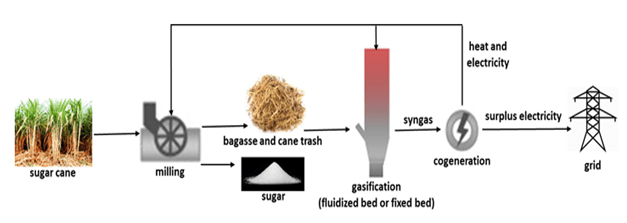
A biomass gasification power plant is an advanced renewable energy facility designed to convert a wide range of organic biomass materials into a combustible gas mixture known as producer gas or syngas through partial oxidation at high temperatures in a controlled environment, enabling the generation of electricity, heat, and chemical feedstocks while maximizing energy recovery from otherwise low-value biomass residues. The feedstocks suitable for biomass gasification include woody biomass such as chips, sawdust, and branches, agricultural residues like corn stover, straw, husks, sugarcane bagasse, energy crops including miscanthus and switchgrass, municipal green waste, food processing by-products, and selected industrial biomass residues. Each type of biomass exhibits unique properties—moisture content, volatile matter, fixed carbon, ash composition, and energy density—that directly influence gasification efficiency, syngas composition, and energy yield. To optimize the gasification process, feedstocks typically undergo preprocessing steps including drying, size reduction, grinding, and homogenization, which improve feeding consistency, enhance heat transfer, and enable uniform residence time in the gasifier, ensuring continuous plant operation and stable energy output even with variable biomass streams.
The heart of a biomass gasification power plant is the gasifier itself, where biomass is thermochemically converted into syngas through partial combustion, pyrolysis, and reduction reactions. Gasifiers are designed to operate at high temperatures typically ranging from 800°C to 1,200°C and under controlled oxygen-limited conditions to prevent full combustion while enabling chemical reactions that produce a mixture of carbon monoxide, hydrogen, methane, carbon dioxide, nitrogen, and trace hydrocarbons. The gasification process can be implemented using different reactor designs, including fixed-bed, fluidized-bed, and entrained-flow configurations, each offering advantages in terms of fuel flexibility, conversion efficiency, throughput, and tar formation control. Fixed-bed gasifiers are simple, robust, and suitable for small- to medium-scale applications but may face challenges with tar production, while fluidized-bed gasifiers provide excellent mixing, uniform temperature distribution, and higher throughput, making them suitable for large-scale continuous operations. Entrained-flow gasifiers achieve high reaction rates and low tar formation but typically require finely sized and highly uniform feedstocks.
Thermal management and process control are crucial in biomass gasification plants to maintain optimal reaction conditions, ensure uniform temperature distribution, and maximize syngas yield and quality. Heat within the gasifier is supplied by partial combustion of the biomass itself or auxiliary fuel, and modern plants integrate heat recovery systems to capture thermal energy from syngas cooling and flue gases, which can be used to preheat incoming biomass, maintain gasifier temperature, or supply external heat loads. The syngas produced is rich in combustible components such as carbon monoxide, hydrogen, and methane, but it also contains impurities such as particulate matter, tars, ammonia, hydrogen sulfide, and other trace compounds. To ensure safe and efficient utilization, syngas undergoes cleaning and conditioning through filtration, cyclones, scrubbers, and catalytic tar removal systems before being directed to combined heat and power (CHP) units, gas engines, turbines, or chemical synthesis processes. Advanced syngas conditioning systems allow for optimized energy conversion efficiency, reduce operational maintenance, and extend the lifespan of downstream equipment.
Operational management of biomass gasification power plants relies on sophisticated automation and monitoring systems that continuously track feedstock input, gasifier temperature, pressure, syngas composition, flow rates, and downstream power generation performance. Real-time adjustments to feedstock feed rates, airflow, temperature profiles, and gas cleaning parameters ensure stable syngas production, optimal energy conversion, and minimal formation of undesirable by-products such as tars or unconverted char. Predictive control strategies enable operators to handle heterogeneous biomass feedstocks, maintain consistent syngas quality, and optimize overall plant efficiency. Safety systems are integral to plant operation, addressing high-temperature reactions, overpressure, combustible gas handling, and potential fire hazards. By integrating advanced monitoring, predictive control, and automated safety mechanisms, biomass gasification plants maintain high reliability, operational stability, and safe energy production.
Residue and by-product management is a critical component of biomass gasification plants. Non-combustible ash, char, and other solid residues are collected from the gasifier and downstream equipment, cooled, and handled for potential utilization as soil amendments, industrial materials, or energy recovery through secondary combustion processes. Efficient residue handling systems, including silos, hoppers, conveyors, and pneumatic transport, ensure continuous plant operation, minimize maintenance requirements, and reduce environmental impact. Gas cleaning residues, such as tar and particulate matter collected in scrubbers and filters, are managed to prevent environmental contamination and, in some cases, can be valorized as chemical feedstocks. By integrating residue and by-product management with energy conversion and syngas utilization, biomass gasification plants achieve maximum resource efficiency, reduce waste, and support circular economy practices.
The environmental and economic advantages of biomass gasification power plants derive from their ability to convert low-value biomass residues into high-quality renewable energy, producing electricity, heat, and chemical feedstocks while minimizing greenhouse gas emissions and reducing reliance on fossil fuels. Modular and scalable plant designs allow adaptation to local biomass availability, energy demand, and regulatory requirements, making them suitable for decentralized energy production in rural, industrial, or municipal contexts. By combining advanced feedstock preprocessing, optimized gasifier design, thermal integration, syngas cleaning and conditioning, residue management, and CHP integration, biomass gasification plants achieve high energy efficiency, stable electricity and heat supply, low environmental impact, and operational flexibility. Producing electricity, thermal energy, and syngas from renewable biomass feedstocks while valorizing residues and minimizing emissions, biomass gasification power plants provide a sustainable, versatile, and low-carbon energy solution that contributes to climate change mitigation, energy security, and circular economy objectives, enabling the efficient and responsible use of biomass resources across multiple scales and sectors.
A biomass gasification power plant is a sophisticated renewable energy facility engineered to convert diverse organic biomass into a combustible syngas mixture through partial oxidation at high temperatures in a controlled, oxygen-limited environment, simultaneously generating electricity, thermal energy, and chemical feedstocks while maximizing energy extraction from otherwise underutilized biomass residues. The range of feedstocks suitable for gasification is broad, including woody biomass such as wood chips, sawdust, tree trimmings, and forestry residues, agricultural by-products like corn stover, wheat straw, rice husks, sugarcane bagasse, and energy crops such as miscanthus and switchgrass, as well as municipal green waste, food processing residues, and selected industrial biomass streams. Each feedstock possesses unique physical and chemical characteristics, including moisture content, volatile matter, fixed carbon, ash composition, and calorific value, which directly influence the gasification process, syngas composition, energy yield, and operational stability. To ensure consistent plant performance and optimize energy conversion, feedstocks are often subjected to preprocessing steps such as drying, grinding, size reduction, and homogenization, which standardize particle size, improve feeding reliability, enhance heat transfer within the reactor, and ensure uniform residence time during gasification. Preprocessing also facilitates storage, handling, and transport logistics, allowing the plant to maintain uninterrupted operation and achieve stable energy outputs despite variations in biomass composition or supply availability.
At the core of a biomass gasification power plant is the gasifier, a high-temperature reactor where biomass undergoes partial oxidation, pyrolysis, and reduction reactions to produce syngas—a mixture primarily composed of carbon monoxide, hydrogen, methane, carbon dioxide, nitrogen, and trace hydrocarbons. Gasifiers operate at temperatures typically ranging from 800°C to 1,200°C, with precisely controlled oxygen levels to prevent full combustion while enabling chemical reactions that maximize syngas yield and quality. Different reactor configurations, including fixed-bed, fluidized-bed, and entrained-flow designs, provide advantages in terms of throughput capacity, fuel flexibility, heat distribution, and tar control. Fixed-bed gasifiers are robust, simple to operate, and suitable for small- to medium-scale applications, though they may generate higher tar concentrations, whereas fluidized-bed gasifiers offer superior mixing, uniform temperature distribution, and higher conversion efficiency, making them suitable for continuous, large-scale operations. Entrained-flow gasifiers achieve rapid reaction kinetics, low tar formation, and high syngas quality, although they require finely sized and homogeneous biomass feedstocks. Optimal thermal management is critical to maintain reactor stability, maximize energy recovery, and produce syngas with consistent calorific value. Heat is supplied internally by partial combustion of biomass or auxiliary fuels and externally through integrated heat recovery systems that capture thermal energy from syngas cooling, flue gases, and char combustion, which is then recycled to preheat feedstocks or sustain reactor temperatures, improving overall energy efficiency and reducing external fuel requirements.
The syngas produced in biomass gasification plants undergoes rigorous cleaning and conditioning to remove particulates, tars, ammonia, hydrogen sulfide, and other impurities that could compromise combustion efficiency or damage downstream equipment. Filtration systems, cyclones, scrubbers, and catalytic tar removal units are employed to ensure that the syngas meets specifications for use in combined heat and power (CHP) units, gas engines, turbines, or chemical synthesis processes. Cleaned syngas can be combusted to generate electricity and thermal energy, providing a flexible energy solution that can feed industrial processes, district heating systems, or grid electricity supply. Thermal integration within the plant is essential, with recovered heat from gas cleaning, char combustion, and flue gases used to preheat feedstock, maintain gasifier temperature, or supply external thermal loads. This integration improves overall energy conversion efficiency, stabilizes reactor performance, and minimizes energy losses.
Operational control in biomass gasification power plants relies on advanced digital monitoring and automation systems that continuously track feedstock feed rates, gasifier temperature, pressure, residence time, syngas composition, and downstream power generation performance. Real-time adjustments to airflow, feedstock input, heating profiles, and gas cleaning parameters allow operators to maintain stable syngas quality, optimize energy conversion, and minimize undesirable by-products such as excessive tars or unconverted char. Predictive control algorithms enable dynamic adaptation to heterogeneous feedstocks, ensuring consistent operation even with varying moisture content, calorific value, or particle size. Safety systems are integral to plant operation, addressing high-temperature reactions, combustible gas handling, overpressure, and potential fire hazards, ensuring reliable and secure plant performance. Advanced emissions control measures further reduce atmospheric impact, capturing particulate matter, trace pollutants, and carbon-containing gases to comply with environmental regulations while maintaining the sustainability of the plant.
Residue and by-product management is a vital aspect of biomass gasification plants. Non-combustible ash, char, and residual biomass particles are collected from the gasifier and downstream equipment, cooled, and handled for potential use as soil amendments, industrial materials, or further energy recovery through secondary combustion processes. Gas cleaning residues, including collected tar and particulates, are managed carefully to prevent environmental contamination and can sometimes be valorized as chemical feedstocks. Efficient handling of solid residues through silos, hoppers, conveyors, and pneumatic systems ensures continuous operation, minimizes maintenance requirements, and reduces environmental impact. By integrating residue management with syngas utilization and energy recovery, biomass gasification plants maximize resource efficiency, reduce waste streams, and support circular economy principles, creating a fully integrated energy solution that valorizes all components of biomass feedstocks.
The environmental and economic benefits of biomass gasification power plants stem from their ability to convert low-value biomass residues into high-quality renewable energy while producing heat, electricity, and syngas for multiple applications, significantly reducing greenhouse gas emissions and fossil fuel dependency. Modular and scalable plant designs allow adaptation to local biomass availability, energy demand, and regulatory frameworks, making them suitable for decentralized energy generation in rural, industrial, or municipal settings. By combining advanced feedstock preprocessing, optimized gasifier design, thermal integration, syngas cleaning and conditioning, residue management, and CHP integration, biomass gasification plants achieve high energy efficiency, operational reliability, low environmental impact, and versatile energy outputs. Producing electricity, thermal energy, and syngas from renewable biomass feedstocks while valorizing residues and minimizing emissions, these plants provide a sustainable, low-carbon, and highly flexible solution that supports climate change mitigation, energy security, and circular economy objectives, enabling efficient, responsible, and scalable utilization of biomass resources across diverse sectors and regions.
A biomass gasification power plant represents one of the most advanced methods of converting renewable organic matter into usable energy, creating syngas that can serve as a substitute for fossil-based fuels while enabling flexible energy generation in the form of heat, electricity, or even chemical feedstocks. The principle of a biomass gasification power plant relies on carefully controlled thermal processes in which biomass undergoes partial oxidation in a high-temperature environment where oxygen or air is limited, preventing complete combustion and instead driving pyrolysis and reduction reactions that break down solid biomass into a combustible mixture of gases. This syngas, composed primarily of carbon monoxide, hydrogen, methane, and small quantities of hydrocarbons, becomes the central energy carrier of the system, capable of being combusted in gas engines, turbines, or boilers, or further refined for industrial processes such as Fischer–Tropsch synthesis or hydrogen production. The flexibility of syngas utilization gives biomass gasification power plants a unique role in the renewable energy sector, as they not only generate power but also open pathways to bio-based chemicals and fuels that extend beyond electricity production.
Feedstock availability and preparation are critical for ensuring reliable operation and efficiency in a biomass gasification power plant, as the system depends heavily on the consistency of the biomass supplied to the gasifier. Wood residues, sawdust, forestry waste, crop residues, dedicated energy crops, and even some types of municipal or industrial biomass waste can be used, but their varying levels of moisture, density, ash content, and particle size can significantly affect gasification performance. For this reason, preprocessing steps such as drying, chipping, pelletizing, and grinding are often employed to ensure uniform particle size distribution, stable feeding into the gasifier, and consistent energy release. Moisture control is particularly vital, since excessive water content in biomass reduces thermal efficiency, lowers syngas calorific value, and complicates reactor operation. By carefully conditioning biomass before introducing it into the reactor, plants can optimize thermal transfer, increase conversion efficiency, and ensure that the produced syngas remains within the desired composition range suitable for downstream use. Such preprocessing also enhances the overall reliability of the plant, reducing clogging, uneven flow, and feed interruptions that can otherwise hinder continuous operation.
Inside the gasifier, the design and operating parameters dictate the quality and yield of syngas produced, and biomass gasification power plants employ different gasifier types depending on the application, scale, and feedstock characteristics. Fixed-bed gasifiers offer robustness and simplicity, making them appropriate for small and medium-scale plants, though they tend to produce higher tar concentrations that require extensive cleaning. Fluidized-bed gasifiers are widely used in larger-scale installations because they provide excellent fuel mixing, uniform heat distribution, and greater flexibility for varying feedstocks, while minimizing tar formation. Entrained-flow gasifiers operate at even higher temperatures and achieve near-complete conversion of biomass into syngas with low tar levels, but they demand finely ground biomass with consistent composition, adding complexity to feedstock preparation. Each type has operational trade-offs, but all are designed with precise airflow and temperature control to ensure that the gasification process remains stable, efficient, and adaptable to different biomass sources. The syngas must then be cooled, filtered, and conditioned to remove particulates, tar, ammonia, and other contaminants that could damage downstream engines or turbines, and this gas cleaning process is essential for maintaining both system longevity and environmental compliance.
The utilization of syngas in a biomass gasification power plant provides multiple pathways for energy conversion, with electricity generation often taking center stage. Cleaned syngas can be used directly in internal combustion gas engines, producing reliable power for grid supply or industrial self-consumption. For larger plants, syngas can be fired in gas turbines or integrated into combined cycle configurations, where waste heat from the turbine exhaust is captured in a steam cycle to maximize efficiency. In smaller decentralized plants, syngas is frequently used in combined heat and power (CHP) systems, where both electricity and useful thermal energy are supplied simultaneously to local industries, farms, or district heating networks, achieving energy utilization rates far above those of traditional fossil-fired power stations. The flexibility of syngas also makes it suitable for advanced applications beyond power, including hydrogen production for fuel cells, methanol synthesis, or conversion into liquid biofuels through catalytic processes, expanding the value chain and supporting the integration of biomass into the broader energy transition and green chemistry sectors.
Residue and by-product handling in biomass gasification power plants plays a crucial role in sustainability, efficiency, and environmental performance. The gasification process generates ash, char, and particulate residues that must be managed, and these by-products can often be repurposed rather than discarded. Biochar, a partially carbonized solid remaining after gasification, can serve as a soil amendment that improves soil fertility, water retention, and carbon sequestration, turning what might otherwise be waste into a valuable agricultural resource. Ash can also be processed for use in cement, construction, or fertilizer applications, depending on its composition. Effective by-product management ensures not only that environmental impacts are minimized but also that the plant operates according to circular economy principles, maximizing resource efficiency and creating additional value streams alongside energy production. Residues from gas cleaning, including tar and condensed organic compounds, can also be recovered and sometimes utilized as chemical feedstocks, though careful management is required to prevent environmental contamination.
The environmental benefits of a biomass gasification power plant are profound, as it enables significant reductions in greenhouse gas emissions compared to fossil fuels, contributes to energy security by diversifying the energy mix, and provides a renewable use pathway for agricultural residues, forestry waste, and other organic matter that would otherwise decompose or be incinerated without energy recovery. By capturing the energy potential of biomass through gasification, these plants reduce open burning of residues, cut methane emissions from unmanaged waste, and deliver clean energy to replace coal, oil, or natural gas. Their modular and scalable design means they can be adapted to local biomass resources, whether installed in rural farming areas with abundant crop residues, forestry regions with wood waste, or industrial zones generating organic by-products suitable for conversion. At the same time, advanced control and automation systems within the plant continuously monitor syngas quality, reactor conditions, emissions, and power generation outputs, allowing operators to fine-tune processes for optimal efficiency, reliability, and compliance with strict environmental regulations.
In essence, a biomass gasification power plant combines the versatility of thermal conversion technology with the sustainability of renewable feedstocks, offering a pathway to decentralized, clean, and efficient energy systems that align with global goals for decarbonization and circular resource use. By integrating feedstock preprocessing, optimized gasifier operation, advanced syngas cleaning, efficient power and heat generation, and innovative residue valorization, these plants provide a model for how renewable biomass can be harnessed to deliver not only electricity but also thermal energy, chemicals, and bio-based fuels. The adaptability of gasification to a wide range of feedstocks, scales, and applications ensures that it will continue to play an important role in the evolution of renewable energy infrastructure, bridging the gap between raw biomass resources and the growing global demand for sustainable energy solutions.
A biomass gasification power plant is designed to transform renewable organic matter into a usable form of energy through the controlled conversion of biomass into syngas, a combustible mixture of carbon monoxide, hydrogen, methane, and light hydrocarbons that can be used for power generation, heating, or as a chemical precursor. Unlike direct combustion systems, a biomass gasification power plant relies on partial oxidation of feedstock at high temperatures in an oxygen-limited environment, allowing for a more flexible energy output that can be tailored to electricity generation, combined heat and power, or even advanced applications such as biofuels and hydrogen production. The process begins with the careful preparation of feedstock, which may include wood chips, sawdust, forestry residues, crop waste, and in some cases municipal or industrial biomass streams, all of which must be conditioned through drying, size reduction, and homogenization to ensure consistent flow and efficient conversion inside the gasifier. The type of biomass gasification reactor used, whether fixed-bed, fluidized-bed, or entrained-flow, determines the quality and yield of syngas, as well as the levels of tar, particulates, and other impurities that must be removed before utilization, and this design choice is central to the performance and efficiency of the plant. Once produced, syngas undergoes cleaning and cooling, often through cyclones, scrubbers, filters, or catalytic reformers, to remove contaminants that could otherwise damage engines, turbines, or downstream systems, ensuring that it meets the standards for efficient combustion or chemical conversion. Clean syngas can then be used in gas engines for small and medium-sized installations, in turbines for larger plants, or in combined cycle systems that maximize energy recovery by coupling a gas turbine with a steam cycle. In many cases, biomass gasification power plants are integrated with combined heat and power configurations, enabling both electricity and thermal energy to be supplied simultaneously, thus reaching overall efficiencies much higher than single-output systems and making them particularly suitable for industrial parks, district heating, and agricultural applications. The by-products of gasification, including biochar and ash, can be collected and reused, with biochar providing a means of carbon sequestration and soil improvement while ash can be applied in cement, construction materials, or as a nutrient source depending on its composition. Beyond energy, biomass gasification power plants contribute significantly to environmental sustainability by reducing reliance on fossil fuels, lowering greenhouse gas emissions, and preventing open burning or decomposition of agricultural and forestry residues that would otherwise release methane or carbon dioxide without energy recovery. The modular nature of biomass gasification allows plants to be scaled according to local biomass resources, making them viable for decentralized renewable energy generation in rural communities as well as large-scale installations for industrial energy supply. Modern systems are highly automated, with real-time monitoring and advanced process control to maintain reactor stability, optimize syngas composition, and ensure compliance with emission standards, while safety systems address the challenges of high temperatures, pressurized gases, and flammable mixtures. Overall, a biomass gasification power plant represents a versatile, efficient, and sustainable technology that bridges the gap between raw biomass and modern energy demands, providing renewable electricity, useful heat, and a pathway toward advanced bio-based fuels and chemicals within the framework of the global transition to low-carbon energy systems.
Biomass Combustion Power Plant
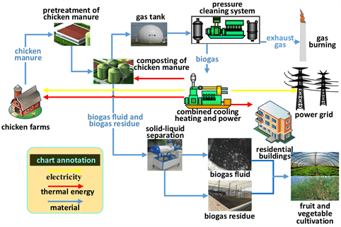
A biomass combustion power plant is a renewable energy facility designed to convert organic biomass materials directly into heat and electricity through the process of controlled combustion. Unlike gasification or pyrolysis, where biomass is first converted into an intermediate fuel like syngas or bio-oil, a biomass combustion plant burns solid biomass directly in a furnace or boiler, producing hot flue gases that transfer thermal energy to water or steam systems for electricity generation and industrial heat applications. The feedstocks used in these plants are highly diverse and can include wood chips, sawdust, forestry residues, agricultural residues such as straw, corn stover, rice husks, sugarcane bagasse, dedicated energy crops, municipal green waste, and selected industrial organic residues. Each type of biomass has specific characteristics—moisture content, calorific value, ash content, and combustion behavior—which influence boiler design, fuel feeding mechanisms, combustion efficiency, emissions, and ash handling. To optimize plant operation, feedstocks are often preprocessed through drying, chipping, shredding, or pelletizing to standardize particle size, reduce moisture content, and improve flow and combustion uniformity, ensuring consistent heat release and maximizing energy recovery from the biomass.
The core of a biomass combustion power plant is the boiler or furnace system, where biomass is burned under controlled conditions to generate high-temperature flue gases. These gases transfer heat to water or steam in the boiler tubes, producing pressurized steam that drives steam turbines connected to electrical generators. Boiler designs vary depending on feedstock type, plant scale, and operational requirements and include grate-fired systems, fluidized-bed boilers, and suspension-fired boilers. Grate-fired systems are well-suited for coarse biomass like wood chips or straw bales, offering reliable combustion with relatively simple fuel handling, while fluidized-bed boilers provide uniform temperature distribution, high fuel flexibility, and efficient combustion for a wide range of biomass particle sizes. Suspension-fired systems, often used in large-scale plants, allow finely ground biomass to be blown directly into the combustion chamber, achieving rapid and complete combustion. Modern biomass combustion plants incorporate advanced combustion control systems that monitor temperature, oxygen levels, and flue gas composition in real time, enabling optimization of combustion efficiency, reduction of unburned residues, and stabilization of steam generation for consistent power output.
Heat recovery and electricity generation in biomass combustion plants are typically achieved through steam turbine systems. The high-pressure steam produced in the boiler is expanded in the turbine, driving an electrical generator to produce electricity, while the exhaust steam can be used for district heating, industrial processes, or additional power generation in combined heat and power (CHP) configurations. CHP integration significantly increases overall plant efficiency, often achieving energy utilization rates above 80 percent by simultaneously providing electricity and thermal energy. In addition to electricity and heat, some biomass combustion plants integrate flue gas cleaning and emissions control systems to minimize environmental impact. These systems include electrostatic precipitators, baghouse filters, cyclones, and wet or dry scrubbers to remove particulate matter, nitrogen oxides, sulfur compounds, and other pollutants, ensuring compliance with stringent emission standards. Advanced monitoring systems continuously track fuel feed, boiler performance, steam pressure and temperature, flue gas composition, and emissions, allowing operators to optimize energy recovery, reduce fuel waste, and maintain safe and reliable operation.
Residue management is a key aspect of biomass combustion power plants. Combustion generates ash and other solid residues that must be collected, cooled, and handled appropriately. Bottom ash and fly ash are typically separated and can be used for applications such as soil amendment, cement production, or construction materials, depending on chemical composition and environmental regulations. Proper handling of ash and residues ensures environmental compliance, reduces operational downtime, and maximizes the circular use of resources. Additionally, biomass combustion plants can be designed with automated fuel feeding, ash removal, and flue gas cleaning systems, which minimize labor requirements, reduce maintenance, and enhance operational safety. By integrating efficient feedstock handling, optimized combustion, heat recovery, and residue management, these plants provide a reliable and continuous supply of renewable electricity and heat from sustainable biomass sources.
The environmental and economic advantages of biomass combustion power plants stem from their ability to transform renewable feedstocks into usable energy while reducing dependence on fossil fuels and contributing to greenhouse gas mitigation. By utilizing residues from agriculture, forestry, and industry, biomass combustion plants help prevent open burning or uncontrolled decomposition of organic matter, reducing methane emissions and minimizing waste. Modular and scalable designs allow these plants to be deployed in rural areas, industrial facilities, or municipal energy networks, matching local biomass availability and energy demand. High operational efficiency, advanced emissions control, and CHP integration make biomass combustion power plants a practical, low-carbon energy solution that supports sustainability goals, energy security, and the circular economy by generating renewable electricity, industrial heat, and district heating while valorizing biomass residues in a safe, efficient, and environmentally responsible manner.
A biomass combustion power plant is a renewable energy facility that converts organic biomass materials directly into usable energy through controlled burning, producing heat, steam, and electricity while maximizing the energy content of diverse biomass feedstocks. Unlike gasification or pyrolysis, which first convert biomass into syngas or bio-oil, combustion systems burn solid biomass in a furnace or boiler, creating high-temperature flue gases that transfer thermal energy to water or steam, which then drives turbines to generate electricity or supplies heat for industrial and district heating applications. The types of biomass feedstocks are varied and can include wood chips, sawdust, forestry residues, agricultural residues such as straw, corn stover, rice husks, and sugarcane bagasse, dedicated energy crops, municipal green waste, and selected organic industrial residues. Each feedstock has specific characteristics—moisture content, particle size, calorific value, ash content, and combustion behavior—that impact boiler design, fuel handling, combustion efficiency, emissions, and ash management. To achieve consistent operation, feedstocks are preprocessed through drying, chipping, shredding, and pelletizing, which reduce moisture, standardize particle size, enhance fuel flow, and ensure uniform combustion, enabling the plant to operate efficiently while maintaining stable steam and electricity production.
The boiler or furnace is the central component of a biomass combustion power plant, where the preprocessed biomass is burned under carefully controlled conditions to produce high-temperature flue gases. These gases heat water in boiler tubes to generate pressurized steam, which is then routed to a steam turbine connected to a generator to produce electricity. Boiler designs vary depending on feedstock type, plant size, and operational objectives. Grate-fired boilers are suitable for coarse biomass and provide simple, robust combustion with reliable ash handling, while fluidized-bed boilers allow excellent fuel mixing, uniform temperature distribution, and high combustion efficiency for a wider range of biomass particle sizes. Suspension-fired boilers, commonly used in large-scale applications, inject finely ground biomass directly into the combustion chamber, enabling rapid and complete combustion. Modern biomass combustion plants utilize advanced combustion control systems that continuously monitor oxygen levels, flame temperature, and flue gas composition to optimize combustion efficiency, reduce unburned residues, minimize fuel waste, and stabilize steam production for consistent electricity generation. Thermal integration within the plant often allows waste heat recovery from flue gases, which can preheat incoming feedstock or provide additional heat for industrial processes, further improving overall efficiency.
Electricity and heat generation in biomass combustion power plants are often coupled through combined heat and power (CHP) systems, which maximize energy utilization by simultaneously producing electrical power and useful thermal energy for heating or industrial applications. CHP integration increases overall efficiency significantly, often reaching energy utilization rates above 80 percent, and makes biomass combustion an attractive option for rural communities, industrial complexes, and municipal heating networks. Emissions control is another critical aspect, as combustion produces particulates, nitrogen oxides, sulfur compounds, and trace pollutants. Biomass combustion plants typically incorporate advanced flue gas cleaning systems such as electrostatic precipitators, baghouse filters, cyclones, wet or dry scrubbers, and selective catalytic reduction units to remove contaminants, comply with environmental regulations, and minimize the ecological footprint. Continuous monitoring systems track fuel feed rates, boiler performance, steam parameters, and emissions in real time, allowing operators to adjust operational parameters for optimal energy efficiency, safe operation, and minimal environmental impact. Residue handling is equally important, as combustion produces ash and char that must be collected, cooled, and managed responsibly. Bottom ash and fly ash can be used as soil amendments, construction materials, or in cement production depending on composition and local regulations, turning plant residues into additional value streams and supporting circular economy principles.
Operational management of biomass combustion power plants requires sophisticated automation and control strategies to balance fuel feed, maintain stable combustion, regulate steam production, and optimize electricity generation. The variability of biomass feedstock, including differences in moisture content, density, and calorific value, necessitates continuous adjustment of air supply, fuel feed rate, and combustion conditions to ensure efficiency and product quality. Modern systems integrate predictive algorithms that anticipate fluctuations in feedstock quality, enabling real-time adjustments that prevent boiler instability, reduce unburned fuel, and optimize emissions. Safety systems are integral to the operation of these high-temperature plants, protecting against overpressure, flammable gas hazards, and boiler tube overheating while ensuring safe ash handling and maintenance operations. By combining robust combustion technology, advanced control systems, emissions mitigation, and efficient residue handling, biomass combustion power plants provide a reliable, continuous source of renewable electricity and heat from sustainable feedstocks.
The environmental and economic benefits of biomass combustion power plants are significant. By utilizing agricultural residues, forestry waste, dedicated energy crops, and other organic by-products, these plants reduce reliance on fossil fuels, lower greenhouse gas emissions, and mitigate methane release from unmanaged biomass decomposition. Modular and scalable designs allow deployment in both rural and urban contexts, adapting to local feedstock availability and energy demand. By integrating fuel preprocessing, optimized combustion, thermal recovery, CHP systems, advanced emissions control, and residue valorization, biomass combustion power plants achieve high operational efficiency, reliability, and sustainability. They deliver renewable electricity and thermal energy while promoting circular economy practices by converting biomass residues into valuable by-products, making them a versatile, environmentally responsible, and economically viable solution for renewable energy generation, climate change mitigation, and local energy security.
A biomass combustion power plant functions as a highly versatile renewable energy facility that directly converts organic biomass into electricity and heat through controlled high-temperature combustion, offering a reliable and efficient pathway to utilize diverse biomass feedstocks while supporting energy sustainability and circular economy principles. The plant can process a wide array of biomass types, including forestry residues such as wood chips, sawdust, bark, and logging waste, agricultural by-products including straw, corn stover, rice husks, and sugarcane bagasse, energy crops like miscanthus and switchgrass, municipal green waste, and selected industrial organic residues, each presenting specific characteristics such as moisture content, calorific value, ash composition, particle size, and combustion behavior, all of which influence boiler design, fuel feeding systems, combustion efficiency, and emissions. To achieve stable and continuous operation, feedstocks are typically subjected to preprocessing procedures including drying, shredding, chipping, pelletizing, or homogenization, which standardize particle size, reduce moisture content, improve flowability, enhance thermal conversion, and allow for consistent energy release within the combustion chamber, thereby optimizing overall plant efficiency and minimizing operational interruptions due to feedstock variability.
The central component of the biomass combustion power plant is the boiler or furnace system, where preprocessed biomass is combusted under controlled conditions to generate high-temperature flue gases that transfer heat to water or steam in boiler tubes, producing pressurized steam that drives turbines connected to electrical generators. The boiler design depends on feedstock type, scale of operation, and efficiency objectives, with common configurations including grate-fired, fluidized-bed, and suspension-fired systems. Grate-fired boilers are widely used for coarse biomass and provide robust, reliable operation with manageable ash handling, while fluidized-bed boilers enhance fuel mixing, maintain uniform temperature distribution, and accommodate a broader spectrum of biomass particle sizes with high combustion efficiency. Suspension-fired boilers inject finely ground biomass directly into the combustion chamber, promoting rapid and complete combustion suitable for large-scale installations. Modern biomass combustion plants incorporate advanced control systems that monitor oxygen levels, flame temperature, flue gas composition, and steam generation parameters in real time, enabling precise adjustments to air supply, fuel feed rate, and combustion conditions to optimize thermal efficiency, minimize unburned fuel, and stabilize steam production for consistent electricity output. In addition, these plants often include thermal integration mechanisms, such as heat exchangers that recover energy from flue gases to preheat incoming feedstock or supply additional process heat, further improving overall energy utilization.
Electricity and heat generation in biomass combustion power plants are frequently integrated through combined heat and power (CHP) systems, which simultaneously deliver electrical power and useful thermal energy for industrial processes, district heating, or agricultural applications, achieving overall energy utilization rates substantially higher than single-output power generation systems. Synergistic CHP integration allows plants to maximize the conversion of biomass energy into usable outputs while reducing fuel consumption and environmental impact. Flue gas cleaning is another critical aspect of plant operation, as biomass combustion produces particulate matter, nitrogen oxides, sulfur compounds, and trace pollutants that must be removed to comply with stringent environmental regulations. Advanced emissions control technologies—such as electrostatic precipitators, baghouse filters, cyclones, wet or dry scrubbers, and selective catalytic reduction systems—are integrated into the plant design to capture contaminants effectively, reduce atmospheric pollution, and ensure regulatory compliance. Continuous monitoring systems track fuel feed rates, combustion efficiency, steam temperature and pressure, turbine performance, and emission levels, allowing operators to make dynamic adjustments that enhance energy recovery, stabilize operation, and maintain environmental safety.
Residue and by-product management is an integral component of biomass combustion power plants. Combustion produces bottom ash and fly ash, which must be collected, cooled, and handled in environmentally responsible ways. Ash can often be repurposed as a soil amendment, in cement and construction materials, or as a nutrient source, depending on its chemical composition and regulatory requirements. Automated systems for ash collection, conveyance, and storage reduce labor demands, minimize maintenance interruptions, and enhance operational safety. Proper handling of these residues contributes to the circular economy by turning by-products into valuable resources while simultaneously ensuring the continuous and efficient operation of the plant. Additionally, careful management of flue gas particulates and condensable residues from emissions control systems helps prevent environmental contamination and may allow for further valorization as industrial feedstocks or materials.
Operational management in biomass combustion power plants relies on sophisticated automation and control strategies to accommodate the variable nature of biomass feedstocks, maintain stable combustion, and ensure continuous energy output. Variations in moisture content, particle size, calorific value, and ash content require continuous adjustments of airflow, fuel feeding rates, combustion temperature, and boiler pressure to maintain optimal performance. Predictive control algorithms and real-time monitoring allow operators to anticipate fluctuations in feedstock characteristics, optimizing combustion efficiency, minimizing unburned fuel, and controlling emissions. Safety systems are essential for high-temperature operations, protecting against overpressure, flammable gas hazards, boiler tube overheating, and ensuring safe ash handling and maintenance procedures. By combining reliable combustion technology with advanced monitoring, emissions control, thermal integration, and residue management, biomass combustion power plants provide a continuous, efficient, and environmentally responsible supply of renewable electricity and heat from sustainable biomass resources.
The environmental and economic advantages of biomass combustion power plants stem from their ability to convert low-value or waste biomass into high-quality energy while reducing reliance on fossil fuels, lowering greenhouse gas emissions, and preventing methane release from uncontrolled decomposition or open burning of organic residues. Modular and scalable plant designs enable deployment across rural, industrial, and urban contexts, allowing adaptation to local biomass availability and energy demand. By integrating feedstock preprocessing, optimized combustion, thermal recovery, CHP systems, advanced emissions control, and residue valorization, biomass combustion power plants achieve high operational efficiency, reliable energy generation, and sustainability. They provide renewable electricity and heat while simultaneously turning residues into valuable by-products, making these plants a practical, low-carbon, and versatile solution for energy security, climate change mitigation, and resource circularity, fully leveraging the potential of biomass as a renewable energy resource.
A biomass combustion power plant is a versatile and highly efficient facility designed to directly convert a wide range of organic biomass materials into heat, electricity, and useful thermal energy through controlled high-temperature combustion, making it a cornerstone technology in renewable energy systems and sustainable resource management. The plant can utilize diverse feedstocks, including forestry residues such as wood chips, sawdust, bark, and logging waste, agricultural by-products including straw, rice husks, corn stover, sugarcane bagasse, energy crops such as miscanthus and switchgrass, municipal green waste, and selected industrial organic residues, each of which possesses distinct properties like moisture content, calorific value, ash content, density, and combustion characteristics that influence fuel handling, boiler operation, emissions, and energy efficiency. To ensure consistent performance and maximize energy conversion, biomass is typically preprocessed through drying, chipping, shredding, pelletizing, or homogenization, which standardize particle size, reduce moisture, improve feeding consistency, and allow for uniform combustion, thereby enhancing thermal efficiency, stabilizing steam production, and minimizing operational interruptions caused by feedstock variability or inconsistent energy content.
The core of the biomass combustion power plant is the boiler or furnace system, where biomass is burned under carefully controlled conditions to produce high-temperature flue gases. These gases transfer heat to water or steam circulating in boiler tubes, generating pressurized steam that drives a turbine connected to an electrical generator, producing renewable electricity. Boiler configurations vary depending on the type of feedstock, plant size, and operational objectives. Grate-fired boilers are common in smaller and medium-scale plants and are suitable for coarse or bulky biomass, offering robust combustion with straightforward ash handling, while fluidized-bed boilers provide excellent fuel mixing, uniform temperature distribution, and higher combustion efficiency, accommodating a wide range of particle sizes and moisture levels. Suspension-fired boilers, often used in large-scale plants, inject finely ground biomass directly into the combustion chamber, achieving rapid, complete combustion with high thermal efficiency. Modern plants are equipped with sophisticated combustion control systems that monitor flame temperature, oxygen levels, steam pressure, and flue gas composition in real time, allowing precise adjustment of fuel feed rate, airflow, and combustion parameters to optimize efficiency, reduce unburned fuel, and stabilize steam production for continuous and reliable electricity generation. Thermal integration within the plant, such as recovering heat from flue gases to preheat incoming biomass or supply process heat, further enhances overall efficiency, reduces fuel consumption, and maximizes the utilization of energy contained in biomass feedstocks.
Electricity generation and heat supply are often combined in biomass combustion plants through integrated combined heat and power (CHP) systems, which simultaneously deliver electrical energy and thermal energy to industrial processes, district heating networks, or agricultural operations. CHP integration allows biomass combustion power plants to achieve overall energy utilization rates that often exceed 80 percent, making them one of the most efficient options for decentralized renewable energy production. Emissions control is a critical aspect of plant operation, as the combustion of biomass produces particulate matter, nitrogen oxides, sulfur compounds, and trace pollutants that must be captured to meet environmental regulations and minimize ecological impact. Advanced emissions control technologies such as electrostatic precipitators, baghouse filters, cyclones, wet or dry scrubbers, and selective catalytic reduction systems are routinely incorporated into plant designs to remove contaminants effectively. Continuous monitoring of fuel feed rates, boiler performance, steam parameters, turbine operation, and emission levels ensures optimal energy conversion, operational stability, and regulatory compliance while providing operators with the ability to dynamically adjust processes in response to changes in feedstock characteristics or load demands.
Residue management plays a central role in the sustainability and efficiency of biomass combustion power plants. The combustion process generates bottom ash and fly ash, which are collected, cooled, and handled according to environmental and safety standards. Depending on chemical composition and local regulations, ash can be repurposed as a soil amendment, used in construction materials, or processed for inclusion in cement production, contributing to circular economy practices by turning by-products into valuable resources. Flue gas cleaning systems also produce residues, including captured particulates and condensable organic matter, which require careful handling to prevent contamination and can sometimes be utilized as secondary feedstocks or industrial materials. Automated fuel feeding, ash removal, and residue handling systems reduce labor requirements, improve operational safety, and allow continuous, high-efficiency operation without frequent interruptions, enabling biomass combustion plants to maintain stable electricity and heat production while minimizing environmental impact.
Operational management of biomass combustion power plants involves a combination of advanced automation, real-time monitoring, and predictive control strategies to accommodate the inherent variability of biomass feedstocks, maintain consistent combustion conditions, and optimize energy output. Differences in moisture content, particle size, calorific value, and ash composition necessitate continuous adjustment of airflow, fuel feed rate, combustion temperature, and boiler pressure to ensure maximum efficiency and minimize emissions. Modern plants employ predictive control algorithms and automated monitoring systems to anticipate fluctuations in fuel quality, optimize combustion, reduce unburned fuel, and maintain safe and reliable operation. Safety systems are crucial for high-temperature combustion, high-pressure steam systems, and handling of flammable biomass and residues, ensuring protection against overpressure, fire hazards, and potential operational failures. By combining precise combustion technology, emissions mitigation, thermal integration, residue management, and advanced operational controls, biomass combustion power plants provide a continuous and environmentally responsible source of renewable electricity and thermal energy.
The environmental and economic advantages of biomass combustion power plants stem from their ability to convert renewable and often low-value biomass feedstocks into usable energy while reducing dependence on fossil fuels, lowering greenhouse gas emissions, and preventing the uncontrolled decomposition or open burning of organic residues that would release methane and carbon dioxide into the atmosphere. Modular and scalable designs allow deployment in rural, industrial, or municipal settings, aligning with local biomass availability and energy demand, and providing flexible solutions for electricity, heat, and combined energy services. By integrating fuel preprocessing, optimized combustion, CHP systems, thermal recovery, emissions control, and residue valorization, biomass combustion power plants achieve high operational efficiency, reliable energy generation, and sustainability. These plants generate electricity and heat from renewable biomass, promote circular resource use by converting residues into valuable by-products, and provide a versatile, low-carbon energy solution that supports climate change mitigation, energy security, and sustainable development across multiple sectors and regions.
Municipal Solid Waste Biomass Power Plant

A municipal solid waste (MSW) biomass power plant is a specialized renewable energy facility designed to convert urban and industrial organic waste streams into electricity and heat through controlled thermal processes, providing a sustainable solution for waste management while generating renewable energy. These plants are capable of processing a wide range of municipal solid waste materials, including food scraps, yard waste, paper, cardboard, wood residues, and other biodegradable or combustible fractions of urban waste, transforming them into energy while significantly reducing the volume of waste destined for landfills. The composition of MSW is highly heterogeneous, with variations in moisture content, calorific value, density, and particle size, which directly affect combustion efficiency, flue gas composition, ash production, and operational stability. To ensure consistent operation and optimize energy recovery, waste is typically subjected to preprocessing, including sorting, shredding, drying, and homogenization, which removes non-combustible materials such as metals, plastics, and glass, and produces a uniform feedstock suitable for combustion or gasification. By standardizing the waste feed, the plant can maintain steady thermal input, improve fuel handling, and enhance overall energy conversion efficiency, while also allowing for flexible integration with other renewable energy systems or combined heat and power (CHP) applications.
At the heart of a municipal solid waste biomass power plant is the combustion or gasification system, which thermally converts the processed waste into heat, electricity, and useful steam. In combustion-based MSW plants, waste is fed into a furnace or boiler where controlled burning generates high-temperature flue gases that transfer thermal energy to water or steam in boiler tubes, producing pressurized steam for turbines and electrical generators. Various boiler designs are employed depending on the nature of the feedstock and plant scale. Moving grate and reciprocating grate systems are commonly used to handle heterogeneous waste with varying moisture content and particle size, providing reliable combustion, effective heat transfer, and efficient ash handling. Fluidized-bed and suspension-fired systems can also be applied, particularly in larger-scale plants, offering uniform temperature distribution, higher thermal efficiency, and better fuel flexibility. Modern MSW biomass plants integrate advanced control systems that monitor oxygen levels, combustion temperature, flue gas composition, and steam parameters in real time, enabling precise adjustments of airflow, fuel feed rate, and combustion conditions to optimize efficiency, reduce unburned residues, and maintain continuous, stable energy production.
Electricity generation in MSW biomass power plants is typically coupled with heat recovery in combined heat and power configurations, which maximizes energy utilization by supplying both electrical energy and thermal energy for district heating, industrial processes, or agricultural applications. CHP integration can significantly increase the overall energy conversion efficiency, often exceeding 70–80 percent, while providing flexible energy outputs tailored to local demand. Flue gas cleaning and emissions control are critical components of these plants due to the variable and potentially contaminant-rich nature of municipal solid waste. MSW biomass plants incorporate multiple layers of pollution control technologies, including electrostatic precipitators, baghouse filters, cyclones, wet and dry scrubbers, and selective catalytic reduction systems to capture particulates, nitrogen oxides, sulfur compounds, heavy metals, dioxins, and other pollutants. Continuous monitoring ensures compliance with strict environmental regulations, protects public health, and minimizes the ecological footprint of energy recovery operations.
Residue management is an essential aspect of municipal solid waste biomass power plants. Combustion produces bottom ash and fly ash, which contain inorganic materials, metals, and other residues that must be collected, cooled, and processed safely. Bottom ash is often recycled into construction materials or used as a road base, while fly ash and particulate residues from flue gas cleaning systems require careful handling and sometimes stabilization before disposal to prevent environmental contamination. Metals recovered from ash and preprocessing stages can be recycled, further enhancing the plant’s contribution to resource recovery and the circular economy. Automated systems for fuel feeding, combustion control, ash collection, and residue handling improve operational efficiency, reduce labor requirements, and maintain safe and reliable plant performance, ensuring continuous electricity and heat generation from the processed waste.
Operational management in municipal solid waste biomass power plants requires advanced automation, monitoring, and control strategies due to the heterogeneous nature of feedstock and the complex thermal processes involved. Variations in waste composition, moisture content, and calorific value necessitate real-time adjustments of combustion parameters, airflow, fuel feed, and boiler pressure to maintain efficiency, minimize unburned residues, and ensure stable steam and electricity production. Safety systems are critical for high-temperature operations, pressurized steam, and flammable gas handling, while predictive algorithms allow operators to anticipate fluctuations in feedstock quality and optimize combustion, energy recovery, and emissions control. The integration of thermal energy recovery, emissions management, and residue valorization ensures that municipal solid waste biomass power plants operate efficiently, sustainably, and with minimal environmental impact.
The environmental and economic benefits of municipal solid waste biomass power plants are significant. By converting urban organic waste into renewable electricity and thermal energy, these plants reduce the volume of waste sent to landfills, prevent uncontrolled decomposition and methane emissions, and provide a clean energy source that displaces fossil fuels. They contribute to greenhouse gas reduction, resource recovery, and the circular economy by transforming waste into usable energy and secondary materials, while also supporting local energy security. Modular and scalable designs allow deployment in cities, industrial zones, or rural communities, adapting to available waste streams and energy demand. Through the combination of advanced preprocessing, optimized combustion or gasification, energy recovery, CHP integration, emissions control, and residue management, municipal solid waste biomass power plants provide a reliable, low-carbon, and environmentally responsible solution for sustainable waste management and renewable energy generation, turning urban and industrial residues into a valuable, continuous source of electricity and heat while promoting efficient and responsible resource use.
A municipal solid waste (MSW) biomass power plant represents a highly strategic solution that integrates renewable energy generation with sustainable waste management, transforming urban and industrial organic waste streams into electricity, heat, and steam while minimizing the environmental impacts associated with landfilling and uncontrolled decomposition. The feedstock for such plants is highly heterogeneous, consisting of food waste, yard trimmings, paper, cardboard, wood residues, biodegradable packaging, and other combustible fractions of municipal and industrial waste, each with variable moisture content, calorific value, ash content, density, and chemical composition. These variations directly influence combustion efficiency, flue gas composition, ash production, and operational stability, making preprocessing a critical component of plant operation. Waste preprocessing includes sorting to remove metals, plastics, and glass, shredding to reduce particle size, drying to lower moisture content, and homogenization to produce a consistent feedstock suitable for continuous thermal conversion. By standardizing the feedstock, the plant ensures stable combustion, improved heat release, and more efficient steam and electricity generation while minimizing the risk of system interruptions caused by inconsistent fuel quality.
The central component of an MSW biomass power plant is its thermal conversion system, typically a furnace or boiler where preprocessed waste is combusted under controlled conditions to produce high-temperature flue gases that transfer heat to water or steam circulating in boiler tubes. This process generates pressurized steam that drives turbines connected to electrical generators, producing renewable electricity for industrial, municipal, or commercial use. Various boiler designs are employed depending on feedstock characteristics and plant scale, with moving grate and reciprocating grate boilers commonly used to handle the heterogeneous and variable moisture content of MSW, ensuring robust combustion, efficient heat transfer, and reliable ash handling. Fluidized-bed boilers offer uniform temperature distribution, excellent fuel mixing, and higher combustion efficiency, accommodating diverse particle sizes and compositions, while suspension-fired boilers are applied in large-scale operations to enable rapid and complete combustion of finely shredded waste. Modern MSW biomass plants are equipped with advanced control systems that continuously monitor flame temperature, oxygen levels, steam pressure, and flue gas composition, allowing operators to dynamically adjust fuel feed rates, airflow, and combustion parameters to optimize efficiency, reduce unburned residues, and maintain continuous, stable energy production. Thermal integration strategies, including heat recovery from flue gases for preheating incoming waste or supplying industrial processes, further enhance overall efficiency and reduce reliance on supplemental fuels.
Electricity generation in MSW biomass plants is frequently integrated with heat recovery in combined heat and power (CHP) configurations, which simultaneously supply electricity and thermal energy to district heating networks, industrial processes, or agricultural applications. CHP integration allows these plants to achieve overall energy conversion efficiencies of 70–80 percent or higher, maximizing the use of energy stored in municipal waste and providing flexible outputs tailored to local energy demand. Emissions control is a critical operational requirement due to the complex and contaminant-rich nature of MSW. Advanced flue gas cleaning technologies are employed, including electrostatic precipitators, baghouse filters, cyclones, wet and dry scrubbers, and selective catalytic reduction systems, to capture particulates, nitrogen oxides, sulfur compounds, dioxins, heavy metals, and other pollutants, ensuring compliance with stringent environmental regulations and minimizing the plant’s ecological footprint. Continuous monitoring and automated control of combustion conditions, flue gas treatment, and emissions allow operators to maintain optimal energy recovery, stable operations, and regulatory compliance while ensuring public health and environmental safety.
Residue and by-product management is a vital aspect of MSW biomass power plant operation. Combustion generates bottom ash and fly ash, which are collected, cooled, and processed in compliance with environmental standards. Bottom ash, containing inert inorganic materials, can be repurposed for construction, road base, or other industrial applications, while fly ash and captured particulates from flue gas cleaning may require stabilization or specialized disposal to prevent contamination. Metals recovered from preprocessing and ash handling can be recycled, further enhancing the plant’s contribution to the circular economy. Automated systems for fuel feeding, combustion control, ash removal, and residue handling reduce labor requirements, increase operational reliability, and ensure continuous energy production while maintaining a safe working environment. By valorizing residues and integrating waste-to-energy processes, MSW biomass power plants effectively combine energy generation with sustainable resource recovery.
Operational management of MSW biomass power plants involves a complex interplay of advanced automation, real-time monitoring, and predictive control strategies to accommodate the inherent variability of municipal solid waste feedstock. Variations in calorific value, moisture content, particle size, and chemical composition necessitate continuous adjustment of combustion parameters, fuel feed rate, airflow, and boiler pressure to maintain optimal thermal conversion and minimize unburned residues. Predictive algorithms allow operators to anticipate fluctuations in waste quality, optimize combustion efficiency, and control emissions, while safety systems ensure protection against high-temperature hazards, pressurized steam systems, and flammable gases. Integration of advanced thermal recovery, emissions management, and residue valorization ensures that the plant operates efficiently, safely, and sustainably, providing reliable electricity and heat generation from renewable organic waste.
The environmental and economic benefits of MSW biomass power plants are substantial, as they provide a sustainable solution for urban waste management while producing clean energy. By diverting biodegradable waste from landfills, these plants reduce methane emissions, minimize leachate formation, and decrease the environmental burden of waste disposal. They also displace fossil fuels by generating renewable electricity and heat, contributing to greenhouse gas mitigation and energy security. Modular and scalable designs enable deployment across cities, industrial zones, and rural communities, adapting to local waste availability and energy demand. Through the integration of advanced preprocessing, optimized combustion, CHP systems, thermal energy recovery, emissions control, and residue valorization, MSW biomass power plants provide a reliable, low-carbon, and environmentally responsible method for transforming municipal solid waste into a continuous, high-value source of renewable energy while promoting sustainable resource management and supporting circular economy objectives.
A municipal solid waste (MSW) biomass power plant is a highly effective solution for simultaneously addressing urban waste management challenges and renewable energy generation, transforming heterogeneous municipal and industrial organic waste into electricity, heat, and useful steam while reducing landfill burden and associated greenhouse gas emissions. These plants process a broad range of waste materials, including food scraps, yard trimmings, paper, cardboard, wood residues, biodegradable packaging, and other combustible fractions of municipal solid waste, as well as select organic industrial by-products. Each feedstock presents unique characteristics—moisture content, calorific value, ash content, density, chemical composition, and particle size—that directly affect combustion efficiency, energy output, emissions, and residue production. To ensure continuous and efficient operation, incoming waste undergoes preprocessing, which can include sorting to remove metals, plastics, and glass, shredding to reduce particle size, drying to lower moisture content, and homogenization to create a consistent, uniform feedstock. Standardization of the waste allows for stable combustion, improved thermal conversion, and consistent steam and electricity generation, mitigating operational challenges caused by the variability of municipal waste streams.
The thermal conversion process is at the heart of an MSW biomass power plant, where preprocessed waste is combusted under controlled conditions to produce high-temperature flue gases that transfer heat to water or steam in boiler tubes. The resulting pressurized steam drives turbines connected to generators to produce renewable electricity, while residual heat can be captured for industrial processes or district heating applications. Boiler and furnace designs vary according to feedstock characteristics and plant scale. Moving grate and reciprocating grate systems are common in handling heterogeneous waste with variable moisture content, providing reliable combustion, effective heat transfer, and manageable ash handling. Fluidized-bed boilers offer uniform temperature distribution, excellent fuel mixing, and high combustion efficiency, accommodating a wide variety of particle sizes and moisture levels, while suspension-fired systems in larger plants inject finely shredded waste into the combustion chamber for rapid, complete combustion and maximized thermal efficiency. Modern MSW biomass plants are equipped with sophisticated monitoring and control systems that continuously measure flame temperature, oxygen concentration, steam parameters, and flue gas composition, enabling real-time adjustments of fuel feed rates, airflow, and combustion conditions to optimize efficiency, reduce unburned residues, and ensure stable energy generation. Thermal integration strategies, including flue gas heat recovery to preheat incoming feedstock or supply industrial process heat, further enhance overall plant efficiency and reduce dependence on supplemental fuel sources.
Electricity production in MSW biomass plants is often integrated with combined heat and power (CHP) systems, which allow simultaneous generation of electricity and usable thermal energy for industrial operations, district heating, or agricultural applications. CHP integration significantly increases the overall energy utilization, often exceeding 70–80 percent, and allows the plant to deliver flexible energy outputs that can adapt to local demand profiles. Emissions control is a crucial component due to the heterogeneous and potentially contaminant-rich nature of municipal waste. Advanced flue gas cleaning systems, including electrostatic precipitators, baghouse filters, cyclones, wet and dry scrubbers, and selective catalytic reduction units, remove particulate matter, nitrogen oxides, sulfur compounds, dioxins, heavy metals, and other pollutants, ensuring compliance with stringent environmental standards and minimizing ecological impact. Continuous monitoring of combustion, flue gas composition, and emission levels allows operators to dynamically optimize energy recovery, maintain operational stability, and protect public health and the environment.
Residue management is a key operational and environmental consideration for MSW biomass power plants. Combustion produces bottom ash and fly ash, which must be collected, cooled, and managed in accordance with environmental regulations. Bottom ash, often containing inert materials, can be reused in construction, road base, or other industrial applications, while fly ash and particulate residues captured from flue gas treatment systems require careful stabilization or safe disposal to prevent contamination. Metals recovered from preprocessing and ash handling stages can be recycled, contributing to circular economy practices and enhancing the sustainability of plant operation. Automated systems for fuel feeding, ash collection, residue transport, and combustion control reduce labor requirements, increase operational efficiency, and allow continuous operation with minimal human intervention, ensuring steady electricity and heat production while maintaining safety and environmental compliance.
Operational management of MSW biomass plants relies on sophisticated automation, predictive control algorithms, and real-time monitoring systems to manage the complex variability of municipal waste feedstock. Differences in calorific value, moisture content, particle size, and chemical composition necessitate constant adjustments in fuel feeding, airflow, combustion temperature, and boiler pressure to maintain optimal thermal conversion and minimize unburned residues. Predictive control strategies anticipate fluctuations in feedstock characteristics, enabling operators to maintain steady combustion, optimize energy recovery, and ensure compliance with emissions regulations. Safety systems protect against high-temperature hazards, pressurized steam, flammable gases, and potential operational failures, while ensuring safe handling of residues and ash. By integrating advanced combustion technology, real-time monitoring, emissions control, thermal integration, and residue valorization, MSW biomass power plants provide a reliable and continuous source of renewable electricity and heat while addressing critical urban waste management challenges.
The environmental and economic benefits of MSW biomass power plants are substantial. By diverting biodegradable waste from landfills, these plants reduce methane emissions, leachate formation, and the environmental impacts of uncontrolled waste decomposition. They generate renewable electricity and heat that displace fossil fuels, contributing to greenhouse gas mitigation and energy security. Modular and scalable plant designs allow deployment in urban areas, industrial zones, and rural communities, adapting to local waste availability and energy demand. Through the integration of advanced preprocessing, optimized combustion, CHP systems, thermal energy recovery, emissions management, and residue valorization, MSW biomass power plants operate efficiently and sustainably, transforming municipal solid waste into a reliable, low-carbon source of energy while promoting circular economy practices, resource recovery, and sustainable urban development.
A municipal solid waste (MSW) biomass power plant is a sophisticated renewable energy facility that simultaneously addresses urban waste management challenges and the demand for sustainable electricity and heat, converting heterogeneous municipal and industrial organic waste into usable energy while minimizing environmental impact. These plants process a wide range of feedstocks, including food waste, yard trimmings, paper, cardboard, wood residues, biodegradable packaging, and selected organic industrial by-products. Each type of feedstock exhibits unique properties such as moisture content, calorific value, density, ash content, and chemical composition, all of which directly influence combustion efficiency, steam generation, flue gas composition, residue production, and overall operational stability. To optimize energy recovery and ensure consistent operation, incoming waste undergoes extensive preprocessing, which includes sorting to remove non-combustibles like metals, plastics, and glass, shredding to reduce particle size, drying to lower moisture content, and homogenization to produce a uniform and reliable feedstock. By standardizing the feedstock, the plant can achieve stable combustion, maximize heat release, and maintain continuous electricity and heat generation while minimizing the risks of unburned fuel, system inefficiencies, and operational interruptions caused by variable waste composition.
The core of an MSW biomass power plant is its thermal conversion system, typically a boiler or furnace where preprocessed waste is combusted under controlled conditions. The combustion generates high-temperature flue gases that transfer heat to water or steam circulating in the boiler tubes, producing pressurized steam that drives turbines connected to electrical generators, creating renewable electricity. The design of the combustion system depends on the nature of the feedstock and the scale of the plant, with moving grate and reciprocating grate boilers commonly employed for heterogeneous MSW due to their robustness, ability to handle varying moisture content, and efficient ash management. Fluidized-bed boilers, with their uniform temperature distribution and high fuel flexibility, are suitable for diverse particle sizes and mixed feedstocks, while suspension-fired systems in large-scale installations allow finely shredded waste to combust rapidly and completely, maximizing thermal efficiency. Advanced plant control systems continuously monitor combustion parameters such as flame temperature, oxygen concentration, boiler pressure, and steam flow, allowing operators to dynamically adjust fuel feed rates, airflow, and combustion conditions to optimize energy efficiency, reduce unburned residues, and maintain stable, uninterrupted electricity production. Thermal integration strategies, such as flue gas heat recovery to preheat incoming waste or supply process heat, further enhance energy utilization and reduce supplementary fuel requirements.
Electricity and heat production in MSW biomass plants are often integrated into combined heat and power (CHP) configurations, which allow simultaneous generation of electrical power and usable thermal energy for industrial applications, district heating networks, or agricultural processes. CHP integration significantly increases overall energy efficiency, often achieving 70–80 percent utilization of the energy content of the waste. Flue gas cleaning and emissions control are crucial due to the potentially contaminant-rich nature of municipal solid waste. Advanced emission control technologies—including electrostatic precipitators, baghouse filters, cyclones, wet and dry scrubbers, and selective catalytic reduction systems—effectively remove particulate matter, nitrogen oxides, sulfur compounds, dioxins, heavy metals, and other pollutants. Continuous monitoring ensures compliance with strict environmental regulations, minimizes ecological impact, and protects public health while allowing operators to optimize combustion and energy recovery. Residue management is equally important; combustion produces bottom ash and fly ash, which must be collected, cooled, and managed in compliance with environmental and safety standards. Bottom ash can often be recycled into construction materials or road base, while fly ash and residues from flue gas treatment require careful handling, stabilization, or safe disposal. Metals recovered during preprocessing and ash handling can be recycled, further contributing to circular economy practices and enhancing sustainability.
Operational management of MSW biomass power plants relies on advanced automation, predictive control algorithms, and real-time monitoring to manage the variable nature of municipal waste feedstocks. Variations in calorific value, moisture content, particle size, and chemical composition require continuous adjustment of fuel feed, airflow, combustion temperature, and boiler pressure to maintain optimal energy conversion and minimize unburned residues. Predictive control systems anticipate changes in feedstock quality, optimizing combustion efficiency, stabilizing steam and electricity production, and ensuring emissions remain within regulatory limits. Safety systems are critical to protect against high-temperature hazards, pressurized steam, flammable gases, and operational failures, while ensuring safe handling of residues and ash. By integrating advanced combustion technology, real-time monitoring, thermal energy recovery, emissions control, and residue valorization, MSW biomass power plants provide a reliable, sustainable, and continuous source of renewable electricity and heat.
The environmental and economic advantages of MSW biomass power plants are significant, as they provide a sustainable solution for urban waste management while generating clean energy. By diverting biodegradable waste from landfills, these plants reduce methane emissions, leachate formation, and the environmental impact of uncontrolled waste decomposition. They supply renewable electricity and thermal energy that displaces fossil fuel use, contributing to greenhouse gas mitigation and energy security. Modular and scalable designs allow deployment across urban, industrial, and rural areas, adapting to local waste availability and energy demand. Through the integration of preprocessing, optimized combustion, CHP systems, thermal recovery, emissions management, and residue utilization, MSW biomass power plants operate efficiently, sustainably, and economically, transforming municipal solid waste into a low-carbon, high-value energy source while promoting circular economy practices, resource recovery, and sustainable urban development.
Animal Waste Biomass Power Plant

An animal waste biomass power plant is a specialized renewable energy facility that converts livestock manure, poultry litter, slaughterhouse residues, and other animal-derived organic waste into electricity, heat, and usable biogas through controlled thermal or biological processes, offering an environmentally sustainable solution for animal farming operations while addressing energy needs. The feedstock for such plants is highly variable in moisture content, calorific value, nitrogen content, and organic composition, factors that significantly influence the choice of conversion technology, efficiency, and emissions. To optimize energy recovery and ensure reliable operation, animal waste is often pretreated through drying, grinding, or homogenization to achieve uniform particle size, reduce excess moisture, and facilitate consistent feeding into the combustion or anaerobic digestion systems. By standardizing feedstock properties, plants can maintain stable energy production, reduce operational disruptions, and maximize the efficiency of the conversion process while simultaneously reducing odors, pathogens, and potential environmental contamination associated with raw animal waste.
In animal waste biomass power plants, energy conversion can occur through several methods, including direct combustion, anaerobic digestion, or co-firing with other biomass feedstocks. In combustion-based systems, dried animal waste is burned in a furnace or boiler to generate high-temperature flue gases that transfer heat to water or steam circulating in boiler tubes, producing pressurized steam to drive turbines and generate electricity. Combustion systems are typically designed with grates, fluidized beds, or suspension-fired arrangements, depending on feedstock characteristics, plant scale, and operational objectives. Fluidized-bed designs are often preferred for animal waste due to their ability to handle heterogeneous feedstock, maintain uniform temperature distribution, and achieve high combustion efficiency while minimizing unburned residues. Suspension-fired systems, suitable for finely processed animal waste, allow rapid and complete combustion, producing high-temperature steam for turbine generation. Advanced control systems continuously monitor combustion temperature, oxygen concentration, steam pressure, and emissions, enabling precise adjustment of airflow, fuel feed, and operating conditions to optimize thermal efficiency, stabilize energy output, and maintain environmental compliance.
Anaerobic digestion is another widely applied technology in animal waste biomass power plants, particularly suited for high-moisture and nutrient-rich residues such as slurry, manure, and poultry litter. In this biological process, microorganisms decompose organic matter in the absence of oxygen, producing biogas composed primarily of methane and carbon dioxide, which can be used as a fuel for combined heat and power (CHP) systems or upgraded to biomethane for grid injection or vehicle fuel. The digestion process reduces the volume of waste, stabilizes organic matter, mitigates odors, and produces nutrient-rich digestate that can be applied as fertilizer, closing nutrient cycles in agricultural operations. Digesters are typically designed as continuously stirred tanks, plug-flow systems, or covered lagoons, with process control parameters such as temperature, pH, hydraulic retention time, and mixing carefully managed to maximize biogas yield, ensure stable operation, and prevent process inhibition.
Emissions control and environmental management are critical for animal waste biomass power plants, as animal residues contain nitrogen, sulfur, and trace elements that can produce ammonia, hydrogen sulfide, particulate matter, and nitrogen oxides during energy conversion. Modern plants integrate flue gas cleaning systems, including scrubbers, biofilters, cyclones, and selective catalytic reduction systems, to remove pollutants and control odor emissions, ensuring compliance with stringent environmental standards. Continuous monitoring of emissions, combustion parameters, and biogas quality allows operators to optimize plant performance while minimizing ecological impact and health risks. Residue management is also essential; combustion produces ash that may be used as soil amendment or in construction, while digestate from anaerobic digestion provides a nutrient-rich fertilizer, promoting circular economy practices and reducing reliance on chemical fertilizers. Automated systems for feedstock handling, combustion or digestion control, and residue management enhance operational efficiency, reduce labor requirements, and enable continuous, reliable energy production.
Operational management of animal waste biomass power plants requires sophisticated automation, predictive control, and real-time monitoring due to the variability of feedstock composition and moisture content. Variations in nitrogen content, fiber composition, and moisture can influence combustion behavior, biogas yield, and emissions, necessitating dynamic adjustments of fuel feed rate, airflow, digester mixing, temperature, and retention times. Safety systems are critical for high-temperature combustion, pressurized steam, flammable biogas, and handling of corrosive or odorous residues, ensuring safe operation for personnel and surrounding communities. By integrating advanced feedstock preprocessing, optimized combustion or anaerobic digestion, CHP energy recovery, emissions control, and residue valorization, animal waste biomass power plants provide a continuous, reliable, and environmentally sustainable source of renewable electricity, heat, and fertilizer, turning agricultural and livestock residues into high-value resources while mitigating the environmental impacts of unmanaged animal waste.
The environmental and economic benefits of animal waste biomass power plants are substantial, as they provide a sustainable approach to energy generation while addressing the challenges of livestock and poultry waste management. By diverting organic waste from landfills, open pits, or uncontrolled decomposition, these plants reduce methane and ammonia emissions, minimize groundwater contamination, and mitigate odors. They supply renewable electricity and heat, reducing dependence on fossil fuels and contributing to greenhouse gas mitigation and local energy security. Modular and scalable plant designs enable deployment across farms, agricultural clusters, and rural communities, adapting to available feedstock and energy demand. Through the integration of feedstock preprocessing, optimized combustion or anaerobic digestion, CHP systems, emissions control, and residue valorization, animal waste biomass power plants operate efficiently, sustainably, and economically, transforming livestock residues into a low-carbon source of energy and fertilizer, supporting circular economy practices, and promoting sustainable agricultural development while providing clean, renewable energy.
An animal waste biomass power plant is a highly efficient and environmentally responsible facility designed to convert livestock manure, poultry litter, slaughterhouse by-products, and other animal-derived organic residues into renewable energy, typically in the form of electricity, heat, or biogas, while simultaneously addressing the environmental challenges associated with animal waste management. The feedstock for such plants is inherently heterogeneous, containing varying moisture levels, fiber content, nitrogen, phosphorus, and other nutrients, all of which significantly influence the choice of energy conversion technology, the efficiency of the process, and the environmental impact of the operation. To optimize energy output and maintain stable plant performance, animal waste is often subjected to preprocessing steps such as dewatering, drying, grinding, and homogenization, which reduce excess moisture, standardize particle size, and ensure uniform feeding into combustion or anaerobic digestion systems. Proper preprocessing not only improves the efficiency of energy conversion but also minimizes odors, pathogen loads, and the risk of environmental contamination associated with untreated or unmanaged animal waste, making the plant safer and more reliable in operation.
Energy conversion in an animal waste biomass power plant can be achieved through several complementary technologies, including direct combustion, anaerobic digestion, and co-firing with other biomass materials. In combustion-based systems, processed animal waste is burned in a furnace or boiler to generate high-temperature flue gases that transfer heat to water or steam circulating in boiler tubes, producing pressurized steam that drives turbines connected to electrical generators. Boiler designs such as grate-fired, fluidized-bed, or suspension-fired configurations are selected based on feedstock characteristics and plant scale, with fluidized-bed boilers often preferred for animal waste due to their ability to handle heterogeneous and high-moisture feedstocks while maintaining uniform temperature distribution and achieving high combustion efficiency. Suspension-fired systems, suitable for finely processed animal residues, allow rapid and complete combustion, maximizing thermal energy recovery. Advanced control systems continuously monitor parameters including flame temperature, oxygen concentration, steam pressure, and flue gas composition, allowing precise adjustments to fuel feed, air supply, and combustion conditions to optimize energy conversion, maintain operational stability, and minimize unburned residues or pollutant formation.
Anaerobic digestion is another widely implemented technology for animal waste biomass power plants, particularly suitable for high-moisture and nutrient-rich residues such as manure, slurry, or poultry litter. In this biological process, microorganisms break down organic matter in the absence of oxygen, producing biogas—a mixture primarily of methane and carbon dioxide—that can be used in CHP (combined heat and power) systems for electricity and heat generation or upgraded to biomethane for injection into natural gas grids or as vehicle fuel. Anaerobic digestion also reduces the volume and odor of animal waste, stabilizes organic matter, and produces nutrient-rich digestate that can be applied as fertilizer, closing nutrient cycles in agricultural operations. Digesters are typically designed as continuously stirred tank reactors, plug-flow systems, or covered lagoons, with process control parameters such as temperature, pH, retention time, and mixing optimized to maximize biogas yield, ensure operational stability, and prevent process inhibition.
Environmental management and emissions control are crucial aspects of animal waste biomass power plants due to the potential release of nitrogen compounds, sulfur gases, particulate matter, and odor during energy conversion. Modern plants integrate flue gas cleaning systems such as scrubbers, biofilters, cyclones, and selective catalytic reduction units to remove pollutants, reduce odors, and comply with stringent environmental standards. Continuous monitoring of emissions, combustion performance, and biogas quality allows operators to maintain high energy recovery efficiency while minimizing environmental impact and health risks. Residue management is equally important, as combustion produces ash that can be utilized as a soil amendment or in construction applications, and anaerobic digestion generates digestate that serves as a nutrient-rich fertilizer. Automated systems for fuel feeding, ash handling, digestate management, and process control enhance operational efficiency, reduce labor requirements, and enable continuous, reliable energy production.
Operational management of animal waste biomass plants demands advanced automation, predictive control algorithms, and real-time monitoring due to the variability of animal residues in terms of moisture, nutrient content, and fiber composition. Differences in feedstock characteristics influence combustion stability, biogas production rates, and emissions, requiring dynamic adjustments of fuel feed rates, airflow, digester mixing, temperature, and retention times. Safety systems protect against high-temperature combustion hazards, pressurized steam, flammable biogas, and handling of corrosive or odorous residues, ensuring safe operation for plant personnel and surrounding communities. By combining feedstock preprocessing, optimized combustion or anaerobic digestion, CHP energy recovery, emissions control, and residue valorization, animal waste biomass power plants provide a reliable, sustainable, and continuous source of renewable electricity, heat, and fertilizer, transforming livestock residues into high-value resources and mitigating the environmental impacts of unmanaged animal waste.
The environmental and economic benefits of animal waste biomass power plants are substantial, as they reduce reliance on fossil fuels, mitigate greenhouse gas emissions, and provide a sustainable solution for managing livestock and poultry waste. By diverting animal residues from landfills, open storage, or uncontrolled decomposition, these plants prevent methane and ammonia emissions, minimize odor and leachate generation, and reduce soil and water contamination. They supply renewable electricity and thermal energy that support local energy demand, enhance energy security, and provide cost savings for agricultural operations. Modular and scalable plant designs enable deployment across individual farms, agricultural clusters, and rural communities, adapting to available feedstock volumes and energy requirements. Through the integration of feedstock preprocessing, combustion or anaerobic digestion, CHP systems, emissions management, and residue valorization, animal waste biomass power plants operate efficiently, sustainably, and economically, turning livestock residues into low-carbon energy and fertilizer while supporting circular economy practices, resource recovery, and sustainable agricultural development.
An animal waste biomass power plant is a highly specialized renewable energy facility that converts livestock manure, poultry litter, slaughterhouse by-products, and other animal-derived organic residues into electricity, heat, and biogas, providing a dual benefit of sustainable energy generation and environmentally responsible waste management. Animal waste feedstock is inherently heterogeneous, with varying moisture content, nitrogen and phosphorus levels, fiber composition, and calorific value, all of which significantly influence the selection of conversion technology, process efficiency, and environmental performance. To ensure consistent energy output and operational reliability, feedstock is often pretreated through processes such as dewatering, drying, grinding, and homogenization, which standardize particle size, reduce moisture content, and improve feed consistency. Proper preprocessing enhances combustion or digestion efficiency, reduces odors and pathogens, and minimizes environmental risks, creating a safer and more efficient system for converting animal waste into usable energy.
Energy conversion in animal waste biomass plants can occur through direct combustion, anaerobic digestion, or co-firing with other biomass materials, depending on the moisture content, energy density, and chemical composition of the feedstock. In combustion-based systems, pretreated animal waste is burned in boilers or furnaces to produce high-temperature flue gases, which transfer heat to water or steam circulating through boiler tubes, generating pressurized steam to drive turbines and produce electricity. Boiler designs, including grate-fired, fluidized-bed, and suspension-fired configurations, are selected based on feedstock properties and plant scale. Fluidized-bed boilers are often preferred for animal waste due to their ability to maintain uniform temperature distribution, handle heterogeneous and high-moisture feedstocks, and achieve high thermal efficiency with minimal unburned residues. Suspension-fired systems, suitable for finely processed animal residues, allow rapid and complete combustion, maximizing energy recovery. Advanced monitoring and control systems continuously track parameters such as flame temperature, oxygen levels, steam pressure, and flue gas composition, enabling real-time adjustments to optimize efficiency, stabilize energy output, and minimize emissions.
Anaerobic digestion is another critical technology in animal waste biomass power plants, particularly suitable for high-moisture, nutrient-rich residues such as manure, slurry, and poultry litter. In anaerobic digesters, microorganisms break down organic matter in the absence of oxygen, producing biogas that primarily contains methane and carbon dioxide. This biogas can be utilized in combined heat and power (CHP) systems for electricity and thermal energy production or upgraded to biomethane for injection into natural gas grids or use as vehicle fuel. Anaerobic digestion also stabilizes organic matter, reduces odor, minimizes pathogen load, and produces nutrient-rich digestate that can be applied as fertilizer, closing nutrient cycles in agricultural systems. Digesters are designed as continuously stirred tanks, plug-flow reactors, or covered lagoons, with parameters such as temperature, pH, retention time, and mixing optimized to maximize biogas yield and maintain stable operation.
Environmental management and emissions control are essential in animal waste biomass power plants due to the potential release of nitrogen compounds, sulfur gases, particulates, and odors during energy conversion. Modern plants integrate flue gas cleaning systems such as scrubbers, biofilters, cyclones, and selective catalytic reduction units to capture pollutants and control emissions. Continuous monitoring of combustion or digestion parameters, biogas quality, and emission levels allows operators to maintain high energy recovery efficiency while minimizing ecological impact and health risks. Residue handling is equally critical; combustion produces ash that can be repurposed as soil amendment or in construction, while digestate from anaerobic digestion provides nutrient-rich fertilizer. Automated systems for feedstock handling, ash and digestate management, and process control enhance operational efficiency, reduce labor requirements, and enable continuous, reliable energy production.
Operational management of animal waste biomass power plants requires sophisticated automation, predictive control algorithms, and real-time monitoring to accommodate the variability of feedstock in terms of moisture, fiber content, and nutrient composition. Variations in feedstock properties influence combustion behavior, biogas production rates, and emissions, requiring dynamic adjustments of fuel feed rate, airflow, digester temperature, and retention time. Safety systems are crucial to protect personnel and infrastructure from high-temperature combustion hazards, pressurized steam, flammable biogas, and odorous or corrosive residues. By integrating feedstock preprocessing, optimized combustion or anaerobic digestion, CHP energy recovery, emissions control, and residue valorization, animal waste biomass power plants provide a continuous, sustainable, and environmentally responsible source of renewable electricity, heat, and fertilizer, turning agricultural residues into high-value resources while reducing the environmental footprint of livestock operations.
The economic and environmental benefits of animal waste biomass power plants are significant, as they provide a sustainable approach to livestock waste management while generating renewable energy. By diverting manure and other residues from uncontrolled storage or disposal, these plants reduce methane and ammonia emissions, minimize odors, prevent groundwater contamination, and promote cleaner agricultural operations. Renewable electricity and heat generated from animal waste displace fossil fuel use, contributing to greenhouse gas mitigation and local energy security. Modular and scalable plant designs allow deployment on farms, within agricultural clusters, or across rural communities, adapting to available feedstock volumes and local energy demand. Through the integration of preprocessing, optimized combustion or anaerobic digestion, CHP systems, emissions management, and residue valorization, animal waste biomass power plants operate efficiently, sustainably, and economically, transforming livestock residues into renewable energy and fertilizer while promoting circular economy practices, resource recovery, and sustainable agricultural development.
An animal waste biomass power plant is a highly specialized facility designed to convert livestock manure, poultry litter, slaughterhouse by-products, and other organic residues from animal agriculture into renewable electricity, heat, and biogas, providing both a sustainable energy source and an environmentally responsible solution for managing agricultural waste. Animal waste is inherently heterogeneous, with wide variations in moisture content, fiber composition, nutrient levels, calorific value, and density, all of which affect the choice of energy conversion technology, process efficiency, and emissions control requirements. To optimize performance and ensure consistent energy output, feedstock often undergoes preprocessing, including drying, grinding, dewatering, and homogenization, which standardizes particle size, lowers moisture content, and facilitates continuous and controlled feeding into combustion or anaerobic digestion systems. Proper preprocessing not only enhances the efficiency of energy conversion but also mitigates odors, pathogen load, and environmental contamination, ensuring safer and more reliable plant operation. By creating uniform feedstock conditions, operators can achieve stable combustion or digestion, maximize energy recovery, and minimize unburned residues or process disruptions caused by inconsistent feedstock characteristics.
Energy conversion in animal waste biomass plants can be accomplished through multiple technologies, including direct combustion, anaerobic digestion, and co-firing with other types of biomass. In combustion systems, pretreated animal waste is burned in boilers or furnaces, producing high-temperature flue gases that transfer thermal energy to water or steam circulating in boiler tubes, generating pressurized steam to drive turbines connected to electricity generators. Boiler designs such as moving grate, fluidized-bed, and suspension-fired systems are chosen based on feedstock characteristics and plant scale. Fluidized-bed boilers are particularly well-suited for heterogeneous and high-moisture animal waste, providing uniform temperature distribution, enhanced fuel mixing, and high thermal efficiency, while minimizing unburned residues. Suspension-fired systems, often used for finely processed animal residues, enable rapid and complete combustion, maximizing heat recovery and energy conversion. Advanced monitoring and control systems continuously track combustion parameters including flame temperature, oxygen concentration, boiler pressure, and steam flow, allowing real-time adjustments to fuel feed, air supply, and operating conditions to optimize efficiency, maintain stable energy output, and reduce emissions. Heat recovery strategies, including flue gas preheating and integration with industrial or district heating networks, further enhance overall plant efficiency and reduce dependence on supplemental fuels.
Anaerobic digestion is another key technology in animal waste biomass power plants, particularly effective for high-moisture, nutrient-rich residues such as manure, slurry, and poultry litter. During anaerobic digestion, microorganisms decompose organic matter in the absence of oxygen, producing biogas composed mainly of methane and carbon dioxide. This biogas can be utilized in combined heat and power (CHP) systems for electricity and thermal energy generation or upgraded to biomethane for injection into natural gas grids or as a vehicle fuel. Anaerobic digestion also stabilizes organic matter, reduces odor, minimizes pathogen content, and produces nutrient-rich digestate that can be applied as fertilizer, closing nutrient cycles and promoting sustainable agricultural practices. Digesters are designed as continuously stirred tank reactors, plug-flow systems, or covered lagoons, with careful control of temperature, pH, retention time, and mixing to optimize biogas yield, ensure process stability, and prevent inhibition.
Emissions control and environmental management are critical for animal waste biomass power plants, as animal residues contain nitrogen, sulfur, and trace elements that can produce ammonia, hydrogen sulfide, particulate matter, and nitrogen oxides during energy conversion. Modern facilities integrate flue gas cleaning and odor control technologies such as scrubbers, biofilters, cyclones, and selective catalytic reduction units to minimize pollutants and ensure compliance with strict environmental regulations. Continuous monitoring of emissions, combustion or digestion parameters, and biogas quality allows operators to maintain high energy recovery efficiency while protecting the environment and public health. Residue handling is also a vital part of plant operation; combustion produces ash that can be used as a soil amendment or in construction applications, while digestate from anaerobic digestion serves as a nutrient-rich fertilizer. Automated systems for feedstock handling, combustion or digestion control, and residue management improve operational efficiency, reduce labor requirements, and allow continuous, reliable energy production.
Operational management of animal waste biomass plants requires advanced automation, predictive control, and real-time monitoring due to the variability of feedstock in terms of moisture, fiber, and nutrient content. Changes in feedstock characteristics directly affect combustion stability, biogas yield, and emission levels, necessitating dynamic adjustments to fuel feed rates, airflow, digester mixing, temperature, and retention times. Safety systems are essential to protect personnel and infrastructure from high-temperature combustion hazards, pressurized steam, flammable biogas, and potentially odorous or corrosive residues. By integrating feedstock preprocessing, optimized combustion or anaerobic digestion, CHP energy recovery, emissions control, and residue valorization, animal waste biomass power plants provide a reliable, sustainable, and continuous source of renewable electricity, heat, and fertilizer, transforming livestock and poultry residues into high-value resources while mitigating environmental impacts associated with unmanaged animal waste.
The economic and environmental benefits of animal waste biomass power plants are substantial, as they provide a cost-effective and sustainable approach to energy generation while managing agricultural waste responsibly. By diverting animal residues from open storage, landfills, or uncontrolled decomposition, these plants reduce methane and ammonia emissions, prevent odor and groundwater contamination, and minimize the ecological footprint of livestock operations. Renewable electricity and heat generated on-site or fed into the grid reduce reliance on fossil fuels, supporting greenhouse gas mitigation and enhancing local energy security. Modular and scalable plant designs enable deployment across farms, agricultural clusters, or rural communities, adapting to available feedstock volumes and local energy demand. Through the combination of feedstock preprocessing, optimized energy conversion via combustion or anaerobic digestion, CHP integration, emissions management, and residue valorization, animal waste biomass power plants operate efficiently, sustainably, and economically, turning livestock residues into low-carbon energy and fertilizer while promoting circular economy practices, resource recovery, and sustainable agricultural development.
Algae Biomass Power Plant

An algae biomass power plant is an advanced renewable energy facility designed to harness the energy stored in algae through biological, thermal, or biochemical conversion processes, transforming algal biomass into electricity, heat, biogas, or biofuels while simultaneously contributing to carbon capture, wastewater treatment, and sustainable resource utilization. Algal biomass offers unique advantages compared to traditional terrestrial biomass sources due to its high growth rates, significant lipid and carbohydrate content, and the ability to grow on non-arable land using brackish water, seawater, or nutrient-rich wastewater streams. However, the heterogeneity of algae species, growth conditions, moisture content, lipid concentration, and ash content requires careful feedstock management and preprocessing to ensure consistent energy conversion. Preprocessing may include dewatering, drying, grinding, or homogenization to produce a uniform feedstock suitable for combustion, anaerobic digestion, or thermochemical processing. Proper feedstock standardization is essential to achieve stable thermal or biochemical conversion, optimize energy recovery, and reduce operational challenges associated with variable moisture and nutrient content.
In algae biomass power plants, energy conversion can be achieved through multiple pathways, including direct combustion, pyrolysis, gasification, or anaerobic digestion, as well as biofuel extraction processes such as transesterification for biodiesel production. In thermal conversion systems, dried algal biomass is combusted in specialized boilers to generate high-temperature flue gases that transfer heat to water or steam, producing pressurized steam for turbines to generate electricity. Boiler designs such as fluidized-bed or suspension-fired systems are preferred for algal biomass due to the fine particle size, low density, and variable moisture content of algal feedstocks, allowing efficient combustion, uniform temperature distribution, and minimal unburned residues. Advanced monitoring and control systems continuously track combustion parameters including flame temperature, oxygen concentration, boiler pressure, and steam flow, enabling dynamic adjustments to fuel feed and airflow to optimize thermal efficiency, maintain operational stability, and reduce emissions. Thermal integration strategies, such as utilizing waste heat for algal drying, process preheating, or district heating, further enhance energy efficiency and reduce reliance on supplementary fuel sources.
Anaerobic digestion is another common conversion pathway for algae biomass, particularly for wet algal feedstocks with high moisture and organic content. During anaerobic digestion, microorganisms decompose the organic matter in oxygen-free conditions, producing biogas composed primarily of methane and carbon dioxide. The biogas can be used in combined heat and power (CHP) systems to generate electricity and heat or upgraded to biomethane for injection into natural gas grids or use as a vehicle fuel. Anaerobic digestion also stabilizes residual biomass, reduces odors, and produces nutrient-rich digestate suitable for use as fertilizer or soil amendment, thereby closing nutrient cycles and supporting sustainable agricultural or aquaculture practices. Digesters are designed as continuously stirred tanks, plug-flow reactors, or high-rate anaerobic systems, with careful management of parameters such as temperature, pH, retention time, and mixing to maximize biogas yield, maintain process stability, and prevent inhibition caused by excessive nitrogen, salts, or lipids present in algal biomass.
Environmental management and emissions control are critical for algae biomass power plants, as the conversion of algal biomass can release nitrogen oxides, sulfur compounds, particulates, and volatile organic compounds if not properly managed. Modern facilities integrate flue gas cleaning technologies, including scrubbers, cyclones, baghouse filters, and selective catalytic reduction systems, to remove pollutants and ensure compliance with environmental regulations. Continuous monitoring of combustion or digestion parameters, biogas quality, and emission levels allows operators to optimize energy recovery, maintain regulatory compliance, and minimize ecological impact. Residue management is an essential component, as combustion produces ash that can be used as a soil amendment or in construction applications, while digestate from anaerobic digestion provides a nutrient-rich by-product that can be recycled back into algal cultivation systems, agricultural lands, or aquaculture operations. Automated systems for feedstock handling, energy conversion, and residue management improve operational efficiency, reduce labor requirements, and ensure continuous and reliable energy production.
Operational management of algae biomass power plants demands sophisticated automation, real-time monitoring, and predictive control due to the variability of feedstock composition, moisture content, and biochemical characteristics. Changes in algal species, lipid content, and nutrient levels can affect combustion behavior, biogas yield, and emissions, requiring dynamic adjustments to fuel feed rates, airflow, digester conditions, temperature, and retention time. Safety systems are critical to protect personnel and equipment from high-temperature hazards, pressurized steam, flammable gases, and handling of potentially corrosive or odorous residues. By integrating feedstock preprocessing, optimized combustion or anaerobic digestion, CHP energy recovery, emissions control, and residue valorization, algae biomass power plants provide a continuous, sustainable, and environmentally responsible source of renewable electricity, heat, and bio-products, transforming algae into high-value energy resources while contributing to carbon mitigation and resource efficiency.
The environmental and economic benefits of algae biomass power plants are substantial, as they support renewable energy generation, wastewater treatment, and carbon capture while reducing reliance on fossil fuels and minimizing environmental impacts. By converting algal biomass into electricity, heat, biogas, or biofuels, these plants contribute to greenhouse gas mitigation, energy security, and sustainable resource management. Algal cultivation can utilize marginal lands, saline water, or nutrient-rich wastewater streams, reducing competition with food crops and promoting circular economy practices. Modular and scalable plant designs enable deployment across industrial facilities, agricultural operations, and coastal or inland regions with abundant water and nutrient resources, adapting to feedstock availability and energy demand. Through the integration of feedstock preprocessing, efficient thermal or biochemical conversion, CHP systems, emissions management, and residue valorization, algae biomass power plants operate efficiently, sustainably, and economically, producing renewable energy and valuable by-products while supporting carbon sequestration, resource recovery, and sustainable environmental practices.
An algae biomass power plant is an innovative renewable energy facility designed to exploit the rapid growth and high energy potential of microalgae and macroalgae, converting this biomass into electricity, heat, biogas, or biofuels while simultaneously providing environmental benefits such as carbon capture, wastewater treatment, and nutrient recycling. Algae offer distinct advantages over terrestrial biomass due to their ability to grow on non-arable land, in brackish or saline water, and even in nutrient-rich wastewater, achieving high biomass productivity with a relatively low land footprint. However, algal feedstock is highly variable in terms of moisture content, lipid and carbohydrate concentrations, ash content, and particle size, necessitating careful feedstock management and preprocessing to ensure consistent energy conversion. Preprocessing steps often include dewatering, drying, grinding, and homogenization, producing a uniform and manageable material suitable for combustion, thermochemical processing, or anaerobic digestion. Standardization of algal feedstock is critical for maintaining stable energy production, maximizing thermal or biochemical conversion efficiency, and reducing operational challenges such as inconsistent feed rates, variable combustion behavior, or inhibition in biological systems.
Energy conversion in algae biomass power plants can be achieved through multiple complementary technologies. Direct combustion of dried algae in boilers generates high-temperature flue gases that transfer heat to water or steam, producing pressurized steam that drives turbines for electricity generation. Boiler systems are often designed as fluidized-bed or suspension-fired units, which accommodate the fine particle size, low bulk density, and variable moisture content characteristic of algal biomass, ensuring uniform combustion, high thermal efficiency, and minimal unburned residues. Advanced monitoring and control systems continuously measure combustion parameters such as flame temperature, oxygen levels, boiler pressure, and steam flow, enabling operators to dynamically adjust fuel feed and air supply to optimize efficiency and maintain stable energy output. Heat recovery systems further improve overall plant efficiency, capturing waste heat from flue gases to preheat algal biomass, provide process heating, or supply district heating networks. Co-firing algae with other biomass or waste streams can enhance energy density, stabilize combustion, and provide operational flexibility, allowing continuous energy generation even with feedstock variability.
Anaerobic digestion is a widely employed technology for wet algal biomass, particularly for high-moisture, nutrient-rich species. In digesters, microorganisms decompose organic matter in the absence of oxygen, producing biogas primarily composed of methane and carbon dioxide. This biogas can be used in combined heat and power (CHP) systems to generate electricity and heat or upgraded to biomethane for grid injection or transportation fuel. Anaerobic digestion of algae also stabilizes residual biomass, reduces odors, and produces nutrient-rich digestate that can be used as fertilizer, applied to algal cultivation systems, or utilized in agricultural and aquaculture applications, closing nutrient loops and promoting sustainable resource management. Digesters are carefully designed to optimize conditions such as temperature, pH, hydraulic retention time, and mixing, maximizing biogas yield and maintaining stable operation despite variations in algal composition, lipid content, or nitrogen levels.
Environmental management and emissions control are essential in algae biomass power plants due to potential releases of nitrogen oxides, sulfur compounds, particulates, and volatile organic compounds during energy conversion. Modern facilities employ flue gas cleaning technologies including scrubbers, cyclones, baghouse filters, and selective catalytic reduction units to capture pollutants and ensure regulatory compliance. Continuous monitoring of emissions, combustion efficiency, biogas quality, and process parameters allows operators to maintain high energy recovery while minimizing environmental impact and health risks. Residue management is also a crucial component, as combustion produces ash that can be repurposed as soil amendment or construction material, while digestate from anaerobic digestion offers a nutrient-rich by-product that can enhance agricultural soils or recycle nutrients back into algal cultivation systems. Automated systems for feedstock handling, process control, and residue management improve operational efficiency, reduce labor costs, and allow continuous, reliable energy production.
Operational management of algae biomass power plants requires advanced automation, predictive control, and real-time monitoring due to the inherent variability of feedstock characteristics, including moisture, lipid content, nutrient concentrations, and particle size. Fluctuations in algal species, growth conditions, and biochemical composition affect combustion stability, biogas yield, and emissions, necessitating dynamic adjustments in fuel feeding, airflow, digester temperature, and retention times. Safety systems are critical to protect personnel and equipment from high-temperature combustion hazards, pressurized steam, flammable biogas, and corrosive or odorous residues. By integrating feedstock preprocessing, optimized combustion or anaerobic digestion, CHP energy recovery, emissions management, and residue valorization, algae biomass power plants provide a continuous, sustainable, and environmentally responsible source of renewable electricity, heat, and bio-products, turning algal biomass into high-value energy resources while supporting carbon sequestration, wastewater treatment, and sustainable resource management.
The environmental and economic benefits of algae biomass power plants are substantial, offering a renewable energy source, reducing reliance on fossil fuels, mitigating greenhouse gas emissions, and contributing to circular economy principles. By converting algal biomass into electricity, heat, biogas, or biofuels, these plants utilize water and nutrient resources efficiently, promote sustainable aquaculture and agricultural practices, and support carbon capture efforts. Algal cultivation does not compete with food crops for arable land, can utilize saline or wastewater streams, and can help reduce nutrient pollution from industrial or municipal effluents. Modular and scalable plant designs allow deployment in coastal regions, inland water systems, industrial zones, or wastewater treatment facilities, adapting to feedstock availability and local energy demands. Through the combination of feedstock preprocessing, efficient thermal or biochemical conversion, CHP integration, emissions control, and residue valorization, algae biomass power plants operate efficiently, sustainably, and economically, producing renewable energy and valuable by-products while supporting environmental stewardship, carbon mitigation, and sustainable development.
An algae biomass power plant is a sophisticated renewable energy facility that converts microalgae and macroalgae into electricity, heat, biogas, and biofuels, serving as a multi-functional system that addresses energy needs, carbon mitigation, wastewater treatment, and nutrient recycling. Algae as a feedstock offer remarkable advantages due to their rapid growth rates, high lipid and carbohydrate content, and ability to grow on non-arable land using brackish water, seawater, or nutrient-rich wastewater, thus avoiding competition with food crops and supporting circular economy practices. However, algal biomass is highly variable in moisture content, nutrient concentration, lipid levels, and particle size, which influences energy conversion efficiency, thermal behavior, and emissions. To optimize performance, preprocessing is essential and typically includes dewatering, drying, grinding, and homogenization, producing a uniform feedstock suitable for combustion, thermochemical processes such as pyrolysis or gasification, or biological processes like anaerobic digestion. Standardizing the feedstock ensures stable energy output, reduces operational challenges such as inconsistent combustion or digester inhibition, and enhances overall plant efficiency.
Energy conversion in algae biomass power plants can occur via multiple pathways depending on the feedstock characteristics and desired outputs. In thermal conversion systems, dried or partially dried algal biomass is combusted in boilers to generate high-temperature flue gases, which transfer heat to water or steam circulating through boiler tubes, producing pressurized steam to drive turbines and generate electricity. Boiler designs such as fluidized-bed or suspension-fired systems are ideal for algal biomass due to its low bulk density, fine particle size, and variable moisture content, allowing efficient combustion, uniform temperature distribution, and minimal unburned residues. Advanced control systems monitor flame temperature, oxygen concentration, steam pressure, and flue gas composition in real time, enabling precise adjustments to fuel feed, air supply, and combustion parameters to maximize efficiency, stabilize energy output, and minimize emissions. Thermal integration strategies, including the use of waste heat for drying algae, preheating feedstock, or supplying industrial and district heating, further enhance overall plant efficiency and reduce reliance on supplemental energy sources. Co-firing algal biomass with other organic residues or conventional biomass can improve energy density, stabilize feedstock variability, and allow continuous operation under fluctuating supply conditions.
Anaerobic digestion is a widely adopted method for wet algal biomass, especially for species with high moisture and organic content. In anaerobic digesters, microorganisms break down organic matter in the absence of oxygen, producing biogas primarily composed of methane and carbon dioxide. The biogas can be utilized in combined heat and power (CHP) systems to generate electricity and thermal energy or upgraded to biomethane for injection into natural gas grids or as vehicle fuel. Anaerobic digestion of algae also stabilizes residual biomass, reduces odors, mitigates pathogen content, and produces nutrient-rich digestate that can be recycled into algal cultivation systems, applied to agricultural soils, or used in aquaculture operations, thus closing nutrient loops and supporting sustainable resource management. Digesters are designed to optimize temperature, pH, hydraulic retention time, and mixing to maximize biogas yield and maintain stable operation despite variability in lipid content, nitrogen levels, and biochemical composition.
Environmental management and emissions control are critical for algae biomass power plants because energy conversion can release nitrogen oxides, sulfur compounds, particulates, and volatile organic compounds if not properly controlled. Modern plants integrate flue gas cleaning systems such as scrubbers, cyclones, baghouse filters, and selective catalytic reduction units to minimize pollutants and comply with stringent environmental regulations. Continuous monitoring of emissions, combustion efficiency, biogas composition, and process parameters enables operators to optimize energy recovery, maintain regulatory compliance, and minimize ecological impact. Residue management is also essential; combustion produces ash that can be repurposed as soil amendment or construction material, while digestate from anaerobic digestion serves as a nutrient-rich by-product that enhances soil fertility or returns nutrients to algal cultivation systems. Automated feedstock handling, process control, and residue management systems increase operational efficiency, reduce labor requirements, and enable continuous, reliable energy production.
Operational management of algae biomass power plants demands sophisticated automation, predictive control, and real-time monitoring due to the variability of algal species, moisture content, lipid and carbohydrate levels, and nutrient composition. Variations in feedstock characteristics influence combustion stability, biogas production, emissions, and overall plant efficiency, requiring dynamic adjustments to fuel feeding, airflow, digester temperature, mixing, and retention times. Safety systems are critical to protect personnel and equipment from high-temperature combustion hazards, pressurized steam, flammable biogas, and corrosive or odorous residues. By integrating feedstock preprocessing, optimized thermal or biological conversion, CHP energy recovery, emissions control, and residue valorization, algae biomass power plants provide a continuous, sustainable, and environmentally responsible source of electricity, heat, and bio-products, transforming algal biomass into high-value energy resources while promoting carbon capture, wastewater treatment, and sustainable resource utilization.
The environmental and economic benefits of algae biomass power plants are substantial, as they reduce dependence on fossil fuels, mitigate greenhouse gas emissions, and support circular economy principles by efficiently recycling nutrients and water. By converting algal biomass into electricity, heat, biogas, or biofuels, these plants create a versatile renewable energy solution that can be integrated with wastewater treatment facilities, aquaculture operations, and industrial processes. Algae cultivation does not compete with food production, utilizes non-arable land, and can help manage nutrient-rich wastewater, reducing eutrophication risks. Modular and scalable plant designs enable deployment in coastal areas, inland water bodies, industrial zones, or wastewater treatment plants, adapting to feedstock availability and local energy demand. Through the combination of feedstock preprocessing, efficient thermal or biochemical conversion, CHP integration, emissions management, and residue valorization, algae biomass power plants operate efficiently, sustainably, and economically, producing renewable energy and valuable by-products while supporting carbon mitigation, resource recovery, and environmentally sustainable development.
An algae biomass power plant represents one of the most advanced forms of renewable energy conversion technology, taking advantage of the high productivity and versatility of algae to generate electricity, heat, biogas, and biofuels while also offering environmental benefits such as carbon capture, nutrient recycling, and wastewater treatment. Unlike traditional terrestrial biomass sources, algae can be cultivated in brackish water, saline environments, or even nutrient-rich wastewater streams, eliminating competition with agricultural crops for arable land and freshwater resources. This flexibility makes algae one of the most sustainable and scalable biomass options available. However, the feedstock characteristics of algae—such as high moisture content, variable lipid and carbohydrate fractions, and fine particle size—require specialized handling and preprocessing steps including dewatering, drying, homogenization, and sometimes pelletization to create a stable and uniform input suitable for combustion, gasification, pyrolysis, or anaerobic digestion. These steps are essential not only to ensure smooth energy conversion but also to maximize efficiency, reduce emissions, and stabilize plant operation in the face of feedstock variability.
The conversion technologies employed in an algae biomass power plant are diverse and can be adapted depending on the type of algae used, local energy demand, and desired output products. Direct combustion of dried algae in boilers is one of the most common approaches, where the biomass is burned in fluidized-bed or suspension-fired systems that can accommodate the unique physical properties of algae. The combustion process generates hot flue gases that transfer energy to water or steam, producing pressurized steam to drive turbines and generate electricity. Continuous monitoring of flame temperature, oxygen levels, boiler pressure, and flue gas composition ensures that combustion is efficient, stable, and environmentally compliant. Waste heat recovery systems are integrated to capture excess thermal energy, which can then be used to dry incoming algae, preheat feedstock, or supply district heating, significantly improving overall energy efficiency. In addition, algae can be co-fired with other biomass materials or even fossil fuels to stabilize combustion, increase energy density, and enable operational flexibility.
For high-moisture algae, anaerobic digestion is a particularly effective pathway. In oxygen-free digesters, microorganisms decompose organic matter into biogas, consisting mainly of methane and carbon dioxide. This biogas can be fed into combined heat and power (CHP) systems to produce both electricity and heat or upgraded to biomethane for injection into natural gas networks or as a vehicle fuel. Anaerobic digestion also provides the added benefit of generating nutrient-rich digestate, which can be applied as fertilizer, enhancing agricultural soils or recycled back into algae cultivation systems, creating a closed-loop cycle of nutrient recovery. The design of digesters must carefully control parameters such as pH, temperature, retention time, and mixing to maintain microbial health and maximize methane yield despite fluctuations in algal composition or nitrogen content.
Environmental control plays a vital role in algae biomass power plants because improper conversion can lead to emissions of nitrogen oxides, sulfur oxides, particulates, and volatile organic compounds. Advanced flue gas treatment systems, including scrubbers, selective catalytic reduction, and baghouse filters, are employed to capture and neutralize pollutants, ensuring compliance with strict environmental regulations. The plant also produces valuable by-products such as ash from combustion, which can be repurposed as soil amendment or construction material, and digestate from anaerobic processes, which provides a nutrient-rich material for agricultural or aquacultural use. Automated systems for feedstock handling, emissions monitoring, and process optimization enhance operational reliability, reduce labor intensity, and ensure that energy production is consistent and sustainable.
The operational success of an algae biomass power plant depends heavily on advanced control systems capable of adjusting to the variability inherent in algal feedstocks. Real-time data on moisture levels, calorific value, and biochemical composition inform adjustments in fuel feeding rates, airflow, combustion temperatures, and digester retention times. Such adaptive systems safeguard efficiency, reduce downtime, and prevent potential hazards associated with high-pressure steam systems, biogas handling, or combustion residues. Safety mechanisms are integrated into all stages of the process to mitigate risks from fire, explosion, or toxic emissions, making algae biomass energy not only sustainable but also reliable from an operational perspective.
The broader environmental and economic benefits of algae biomass power plants are considerable. They reduce reliance on fossil fuels, contribute to greenhouse gas reduction by capturing and utilizing CO₂ during algal growth, and offer opportunities for wastewater treatment by consuming excess nutrients in effluents that would otherwise cause eutrophication in natural water bodies. Algae cultivation systems can be deployed on marginal lands, coastal regions, or even offshore, expanding renewable energy potential without encroaching on farmland. Modular and scalable plant designs allow algae biomass power plants to be tailored to local conditions, whether serving as small-scale units for community energy systems or as large industrial complexes integrated with aquaculture, wastewater treatment, or biorefinery operations. By combining feedstock flexibility, advanced energy conversion technologies, emission controls, and resource recovery strategies, algae biomass power plants embody a sustainable, efficient, and innovative approach to renewable energy generation that supports both environmental stewardship and energy security.
Energy Crops Biomass Power Plant
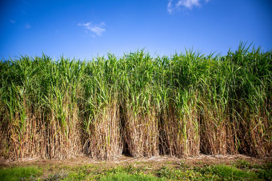
An energy crops biomass power plant is a large-scale renewable energy facility designed to convert dedicated energy crops such as miscanthus, switchgrass, willow, poplar, and other fast-growing, high-yielding plants into electricity, heat, and biofuels, providing a sustainable alternative to fossil fuels while promoting agricultural diversification and carbon sequestration. These energy crops are specifically cultivated for their high biomass productivity and favorable combustion or conversion characteristics, including relatively low moisture content, high cellulose and lignin content, and predictable energy yield, which makes them ideal feedstocks for large-scale biomass power generation. The cultivation of energy crops is strategically planned to optimize land use, soil health, and water efficiency, often employing crop rotation and intercropping systems to enhance sustainability. Feedstock harvesting, storage, and preprocessing are critical components of the plant’s operational design, with crops typically harvested in baled, chipped, or pelletized form and pretreated through drying, grinding, or pelletization to ensure consistent particle size, reduce moisture content, and improve fuel handling, combustion efficiency, and overall energy conversion performance.
Energy conversion in energy crops biomass power plants can be accomplished through multiple technologies, including direct combustion, co-firing with other biomass or fossil fuels, gasification, and anaerobic digestion for certain crop residues. In combustion-based systems, preprocessed energy crops are burned in boilers to produce high-temperature flue gases that transfer heat to water or steam circulating in boiler tubes, producing pressurized steam to drive turbines connected to electricity generators. Boiler types such as moving grate, fluidized-bed, and suspension-fired systems are selected based on the specific characteristics of the energy crop feedstock, including particle size, moisture content, and ash composition. Fluidized-bed boilers are particularly effective for heterogeneous or variable biomass feedstocks, offering uniform temperature distribution, enhanced fuel mixing, and high thermal efficiency while minimizing unburned residues. Co-firing with other biomass types or fossil fuels provides operational flexibility, stabilizes energy output, and enhances the reliability of electricity generation under varying feedstock supply conditions. Advanced control systems continuously monitor combustion parameters including flame temperature, oxygen concentration, steam pressure, and flue gas composition, allowing operators to adjust fuel feed, airflow, and boiler operation dynamically to optimize efficiency, reduce emissions, and maintain operational stability.
Gasification and thermochemical conversion represent alternative pathways for energy crops biomass, where biomass is partially oxidized at high temperatures to produce syngas—a mixture of carbon monoxide, hydrogen, carbon dioxide, and methane—which can be combusted in gas engines or turbines to produce electricity and heat or further processed into biofuels and chemicals. Gasification allows for higher conversion efficiency, greater fuel flexibility, and integration with combined heat and power (CHP) systems, producing both electrical and thermal energy for industrial or district heating applications. Syngas cleaning and conditioning systems are incorporated to remove particulates, tars, and other impurities, ensuring high-efficiency operation and protecting downstream equipment from fouling or corrosion. Integration with CHP systems enhances overall energy utilization, capturing waste heat from electricity generation for preheating feedstock, drying energy crops, or supplying thermal energy to nearby industrial facilities or communities.
Environmental management is a crucial component of energy crops biomass power plants, as combustion and gasification processes can release nitrogen oxides, sulfur oxides, particulates, and volatile organic compounds. Modern plants employ flue gas cleaning systems such as scrubbers, selective catalytic reduction units, baghouse filters, and electrostatic precipitators to minimize emissions and comply with environmental regulations. Residue management is also important, with ash generated during combustion used as a soil amendment or in construction applications, returning essential nutrients such as potassium and phosphorus to agricultural systems and closing nutrient loops. For energy crops integrated with CHP or district heating systems, the plant design ensures maximum utilization of thermal energy, reducing fuel consumption and lowering overall greenhouse gas emissions compared to conventional electricity generation. Automated feedstock handling, combustion control, and residue management systems improve operational efficiency, reduce labor intensity, and ensure continuous and reliable energy production from energy crop feedstocks.
Operational management of energy crops biomass power plants requires careful planning and advanced control systems to handle feedstock variability, seasonal supply fluctuations, and changes in moisture content or calorific value. Dynamic adjustments in fuel feeding, airflow, combustion temperature, and boiler pressure are necessary to maintain stable energy output and prevent operational disruptions. Safety systems are integral, protecting plant personnel and equipment from high-temperature combustion hazards, pressurized steam, and handling of potentially corrosive or abrasive ash residues. By integrating feedstock preprocessing, optimized energy conversion, CHP energy recovery, emissions control, and residue valorization, energy crops biomass power plants provide a sustainable and reliable source of renewable electricity, heat, and bio-products, transforming agricultural energy crops into high-value energy resources while promoting environmental stewardship, carbon sequestration, and agricultural resilience.
The economic and environmental benefits of energy crops biomass power plants are substantial, as they provide a renewable energy source, reduce dependence on fossil fuels, mitigate greenhouse gas emissions, and offer opportunities for rural development and agricultural diversification. By utilizing dedicated energy crops, these plants create a predictable and sustainable feedstock supply, reduce the risk of land degradation, and enhance carbon sequestration in soil and biomass. Modular and scalable plant designs allow deployment at various scales, from small community-based plants integrated with local farms to large industrial-scale facilities supplying electricity and thermal energy to regional grids. Through the integration of feedstock management, advanced energy conversion technologies, CHP systems, emissions control, and residue valorization, energy crops biomass power plants operate efficiently, sustainably, and economically, producing renewable energy and valuable by-products while supporting sustainable agriculture, circular economy practices, and long-term environmental sustainability.
An energy crops biomass power plant is a highly efficient and environmentally sustainable facility designed to convert purpose-grown energy crops into electricity, heat, and biofuels while providing multiple benefits for agriculture, energy security, and carbon management. Energy crops such as miscanthus, switchgrass, willow, poplar, and other fast-growing perennial or annual plants are cultivated specifically for their high biomass yield, low nutrient input requirements, and favorable combustion properties, making them an ideal feedstock for large-scale renewable energy production. These crops are carefully selected and managed to optimize growth cycles, soil fertility, and water use efficiency, often incorporating crop rotation and sustainable agricultural practices to maintain soil health and enhance overall ecosystem resilience. Before entering the energy conversion process, harvested energy crops typically undergo preprocessing steps including drying, chopping, grinding, or pelletizing to standardize particle size, reduce moisture content, and improve handling, storage, and feeding consistency. This preprocessing is essential to ensure efficient combustion, gasification, or anaerobic digestion, enabling stable and predictable energy output while minimizing operational disruptions caused by feedstock variability.
The conversion of energy crops into usable energy can be accomplished through a variety of technologies, each selected based on the specific characteristics of the crop, the scale of the plant, and the desired energy products. Direct combustion of preprocessed energy crops in specialized boilers produces high-temperature flue gases, which transfer thermal energy to water or steam circulating through boiler tubes, generating pressurized steam that drives turbines for electricity production. Boiler types such as moving grate, fluidized-bed, and suspension-fired systems are optimized to handle the bulk density, particle size, and ash characteristics of energy crops, ensuring uniform combustion, high thermal efficiency, and minimal unburned residues. Fluidized-bed boilers, for instance, provide excellent mixing and temperature uniformity, making them suitable for heterogeneous biomass feedstocks with varying moisture content. Co-firing energy crops with other biomass or even conventional fossil fuels can further enhance operational stability, increase energy density, and allow continuous electricity generation even under fluctuations in feedstock supply. Advanced monitoring systems continuously track parameters such as combustion temperature, oxygen levels, steam pressure, and flue gas composition, enabling real-time adjustments to fuel feed and airflow to optimize performance, maximize energy recovery, and minimize emissions.
Gasification and thermochemical conversion represent alternative pathways for energy crops biomass, offering higher efficiency and the ability to produce versatile energy products such as syngas, which contains carbon monoxide, hydrogen, methane, and carbon dioxide. This syngas can be combusted in gas engines or turbines for electricity and heat production or further processed into biofuels and chemicals, allowing integration into larger industrial or energy systems. Gasification systems incorporate advanced syngas cleaning and conditioning equipment to remove particulates, tars, and other impurities, ensuring reliable operation and protecting downstream energy conversion devices. Integration with combined heat and power (CHP) systems allows efficient utilization of waste heat for industrial processes, drying incoming feedstock, or supplying district heating, significantly improving overall energy efficiency and reducing reliance on additional fuel sources. These technologies also provide flexibility to adapt to seasonal variations in crop availability or energy demand, making energy crops biomass plants highly resilient and scalable.
Environmental management is a critical aspect of energy crops biomass power plants, as combustion and gasification processes can emit nitrogen oxides, sulfur oxides, particulates, and volatile organic compounds. Modern facilities employ advanced emission control systems, including scrubbers, baghouse filters, electrostatic precipitators, and selective catalytic reduction units, to mitigate pollutants and ensure compliance with stringent environmental standards. Ash generated during combustion is often rich in nutrients such as potassium and phosphorus and can be recycled back into agricultural systems as a soil amendment, promoting circular nutrient flows and enhancing soil fertility. Integration with CHP or district heating systems maximizes energy utilization, allowing nearly all the energy content of the biomass to be converted into useful electricity or heat while minimizing greenhouse gas emissions. Automated feedstock handling, energy conversion control, and residue management systems reduce labor requirements, improve operational reliability, and enable continuous, uninterrupted energy production from energy crops.
Operational efficiency of energy crops biomass power plants relies on precise management of feedstock variability, seasonal supply fluctuations, and changes in moisture content or calorific value. Advanced automation and predictive control systems dynamically adjust fuel feed rates, combustion temperature, airflow, and boiler pressure to maintain stable energy output and prevent operational disruptions. Safety systems are essential to protect plant personnel and equipment from high-temperature combustion hazards, pressurized steam, and the handling of ash or other residues that may be abrasive or corrosive. By integrating feedstock preprocessing, optimized combustion or gasification processes, CHP energy recovery, emission control systems, and residue valorization, energy crops biomass power plants provide a reliable, sustainable, and continuous source of renewable electricity, heat, and bio-products, transforming dedicated agricultural crops into high-value energy resources while supporting environmental protection, carbon mitigation, and sustainable land management.
The economic and environmental advantages of energy crops biomass power plants are significant, as they create a predictable and sustainable feedstock supply for renewable energy generation, reduce dependence on fossil fuels, and contribute to greenhouse gas mitigation. By cultivating dedicated energy crops, these plants also support rural development, provide additional income streams for farmers, improve land utilization, and promote long-term soil carbon sequestration. Modular and scalable plant designs enable deployment at various sizes, from small community-level facilities integrated with local farms to large industrial-scale plants supplying electricity and thermal energy to regional grids. Through careful integration of feedstock management, advanced energy conversion technologies, CHP systems, emissions mitigation, and residue recycling, energy crops biomass power plants operate efficiently, sustainably, and economically, producing renewable energy and valuable by-products while fostering sustainable agriculture, circular economy practices, and long-term environmental stewardship.
An energy crops biomass power plant is a large-scale renewable energy facility specifically designed to harness the potential of purpose-grown crops such as miscanthus, switchgrass, willow, poplar, and other fast-growing, high-yielding species, converting them into electricity, heat, and biofuels while promoting carbon sequestration, sustainable agriculture, and rural economic development. These crops are selected for their rapid growth, high cellulose and lignin content, low nutrient requirements, and favorable combustion characteristics, making them ideal for large-scale biomass power generation. The cultivation of energy crops is carefully managed to optimize land use, enhance soil fertility, and maintain water efficiency, often incorporating crop rotation and intercropping strategies to preserve ecosystem health and sustain productivity. Harvested crops are typically preprocessed through drying, chopping, grinding, or pelletization to reduce moisture content, standardize particle size, and improve storage and feeding consistency. Preprocessing ensures efficient energy conversion, stabilizes operational performance, and minimizes disruptions caused by variability in feedstock properties such as moisture content, calorific value, and ash composition.
Energy conversion in energy crops biomass power plants can be achieved through multiple technologies, including direct combustion, gasification, co-firing with other biomass or fossil fuels, and, in some cases, anaerobic digestion of crop residues. Direct combustion involves burning preprocessed biomass in specialized boilers, producing high-temperature flue gases that transfer heat to water or steam circulating through boiler tubes, generating pressurized steam that drives turbines for electricity production. Boiler designs, such as fluidized-bed, moving grate, and suspension-fired systems, are selected based on the physical and chemical properties of the biomass, ensuring uniform combustion, high thermal efficiency, and minimal unburned residues. Fluidized-bed boilers are particularly effective for heterogeneous feedstocks, providing excellent mixing and temperature uniformity, while co-firing with other biomass or fossil fuels stabilizes combustion, increases energy density, and allows continuous electricity production even when energy crop availability fluctuates. Advanced monitoring and control systems continuously track combustion parameters such as flame temperature, oxygen concentration, steam pressure, and flue gas composition, enabling real-time adjustments to fuel feed and airflow to optimize performance, maximize energy recovery, and minimize emissions.
Gasification and thermochemical conversion represent alternative pathways for energy crops biomass, allowing the production of syngas composed of carbon monoxide, hydrogen, methane, and carbon dioxide, which can be used in gas engines, turbines, or processed further into biofuels and chemicals. Gasification systems incorporate syngas cleaning and conditioning technologies to remove particulates, tars, and other contaminants, ensuring efficient downstream energy conversion and protecting equipment from corrosion or fouling. Integration with combined heat and power (CHP) systems enhances overall efficiency, capturing waste heat from electricity generation to preheat feedstock, dry incoming crops, or supply thermal energy to industrial facilities or district heating networks. Co-firing, modular plant designs, and seasonal feedstock storage strategies provide operational flexibility, allowing energy crops biomass power plants to adapt to fluctuating availability of feedstock and variable energy demand, ensuring reliable and continuous renewable energy production.
Environmental management is a critical aspect of energy crops biomass power plants, as combustion and gasification can generate nitrogen oxides, sulfur oxides, particulates, and volatile organic compounds. Modern facilities employ advanced flue gas treatment systems, including scrubbers, selective catalytic reduction units, baghouse filters, and electrostatic precipitators, to capture and neutralize emissions, maintaining compliance with strict environmental standards. Residue management is equally important; combustion ash is often nutrient-rich and can be returned to agricultural soils as a soil amendment, recycling essential nutrients such as potassium and phosphorus and supporting sustainable crop production. Integration with CHP systems ensures maximum utilization of energy content, significantly reducing greenhouse gas emissions compared to conventional electricity generation while also enhancing energy efficiency. Automated feedstock handling, combustion control, and residue management systems reduce labor requirements, improve operational reliability, and ensure consistent energy output from energy crop feedstocks.
Operational management of energy crops biomass power plants requires sophisticated automation and real-time control systems capable of responding to seasonal variations, feedstock moisture changes, and differences in calorific value. Dynamic adjustments in fuel feeding, airflow, combustion temperature, and boiler pressure maintain stable energy output and prevent operational disruptions. Safety systems are critical to protect personnel and equipment from high-temperature combustion hazards, pressurized steam, and the handling of abrasive or corrosive ash residues. By combining feedstock preprocessing, optimized energy conversion technologies, CHP integration, emissions control, and residue valorization, energy crops biomass power plants provide a reliable, continuous, and sustainable source of renewable electricity, heat, and bio-products, transforming purpose-grown agricultural crops into high-value energy resources while supporting environmental sustainability, carbon mitigation, and long-term soil and water stewardship.
The economic and environmental benefits of energy crops biomass power plants are significant, offering a renewable energy source that reduces dependence on fossil fuels, mitigates greenhouse gas emissions, and fosters rural economic development. Dedicated energy crop cultivation creates a predictable feedstock supply, enhances land use efficiency, and contributes to soil carbon sequestration, while also providing additional income streams for farmers and rural communities. Modular and scalable plant designs allow deployment at various levels, from small community-based operations integrated with local farms to large industrial-scale plants supplying electricity and thermal energy to regional grids. Through the integration of advanced feedstock management, energy conversion technologies, CHP systems, emissions control, and residue recycling, energy crops biomass power plants operate efficiently, sustainably, and economically, producing renewable energy and valuable by-products while promoting sustainable agriculture, circular economy practices, and long-term environmental stewardship.
An energy crops biomass power plant is a renewable energy facility engineered to convert purpose-grown high-yielding crops such as miscanthus, switchgrass, willow, poplar, and other fast-growing perennials or annuals into electricity, heat, and biofuels, offering a sustainable solution to energy demand while supporting rural economies, agricultural diversification, and carbon mitigation. These energy crops are carefully cultivated to optimize growth rates, maximize biomass yield, and maintain soil health, often employing crop rotation, intercropping, and low-input farming techniques to enhance sustainability and ecosystem resilience. The harvested biomass is subject to preprocessing steps such as drying, grinding, chopping, or pelletizing to reduce moisture content, standardize particle size, and facilitate consistent feedstock handling and storage. This preprocessing ensures that the feedstock is suitable for thermal or biochemical conversion processes, providing uniform combustion or gasification behavior, reducing operational disruptions, and improving overall energy efficiency. By producing a predictable and high-quality biomass supply, the plant can operate continuously and reliably, even when environmental conditions or crop yields vary seasonally.
Energy conversion in energy crops biomass power plants can be achieved through multiple pathways, with direct combustion, co-firing, gasification, and thermochemical processes being the most common. In combustion-based systems, preprocessed energy crops are burned in specialized boilers such as fluidized-bed, moving grate, or suspension-fired units to produce high-temperature flue gases. These gases transfer heat to water or steam circulating in boiler tubes, producing pressurized steam that drives turbines for electricity generation. Fluidized-bed boilers are particularly effective for heterogeneous biomass with varying moisture and particle sizes, ensuring uniform temperature distribution, complete combustion, and minimal unburned residues. Co-firing with other biomass or fossil fuels can stabilize energy output, increase calorific value, and enhance operational flexibility during periods of feedstock scarcity or variability. Advanced monitoring systems track parameters such as flame temperature, oxygen levels, steam pressure, and flue gas composition in real time, allowing dynamic adjustments to fuel feed, airflow, and boiler operation to optimize thermal efficiency, reduce emissions, and maintain operational stability.
Gasification and thermochemical conversion offer alternative, high-efficiency pathways for energy crops biomass, producing syngas composed of carbon monoxide, hydrogen, methane, and carbon dioxide that can be combusted in gas engines or turbines, or further refined into biofuels and chemical intermediates. Gasification systems incorporate syngas cleaning and conditioning to remove particulates, tars, and other impurities, protecting downstream equipment and improving overall conversion efficiency. Integration with combined heat and power (CHP) systems maximizes energy utilization, capturing waste heat for drying incoming feedstock, preheating boilers, or supplying industrial and district heating networks. Modular plant designs, co-firing flexibility, and seasonal storage solutions allow energy crops biomass power plants to maintain reliable energy output and adapt to fluctuations in crop availability, feedstock quality, or local energy demand, ensuring resilience and continuous operation across seasons.
Environmental management is a key aspect of energy crops biomass power plants because combustion and gasification can generate nitrogen oxides, sulfur oxides, particulates, and volatile organic compounds. Modern facilities utilize flue gas cleaning systems such as scrubbers, selective catalytic reduction units, baghouse filters, and electrostatic precipitators to mitigate emissions and comply with environmental regulations. Ash generated during combustion is nutrient-rich and can be applied back to agricultural soils as a soil amendment, returning essential elements such as potassium and phosphorus and supporting circular nutrient cycles. Integration with CHP or district heating systems ensures that nearly all the energy content of the biomass is effectively utilized, significantly reducing greenhouse gas emissions compared to conventional fossil-fuel-based electricity generation. Automated feedstock handling, energy conversion monitoring, and residue management systems enhance operational efficiency, reduce labor requirements, and enable continuous and reliable energy production from energy crop feedstocks.
Operational management of energy crops biomass power plants requires sophisticated automation, real-time monitoring, and predictive control systems capable of handling seasonal variations, feedstock moisture fluctuations, and changes in calorific value or nutrient content. Dynamic adjustments in fuel feeding, combustion air, boiler temperature, and pressure maintain stable energy output while preventing operational disruptions or equipment damage. Safety systems protect plant personnel and equipment from hazards associated with high-temperature combustion, pressurized steam, and handling of abrasive or corrosive residues. By integrating optimized feedstock preprocessing, advanced energy conversion technologies, CHP systems, emission controls, and residue valorization, energy crops biomass power plants provide a continuous, sustainable, and environmentally responsible source of electricity, heat, and bio-products, transforming dedicated agricultural crops into high-value energy resources while promoting carbon sequestration, sustainable land management, and long-term ecosystem benefits.
The economic and environmental benefits of energy crops biomass power plants are substantial, as they provide a predictable renewable energy source, reduce dependency on fossil fuels, and contribute to greenhouse gas mitigation. Cultivation of dedicated energy crops enhances land-use efficiency, improves soil carbon content, supports rural economic development, and provides additional income streams for farmers. Modular and scalable plant designs allow deployment across small community-based facilities integrated with local farms or large industrial-scale plants supplying electricity and thermal energy to regional grids. By combining feedstock management, energy conversion, CHP integration, emissions control, and residue recycling, energy crops biomass power plants operate efficiently, sustainably, and economically, producing renewable energy and valuable by-products while supporting sustainable agriculture, circular economy principles, and long-term environmental stewardship.
Corn Stover Biomass Power Plant
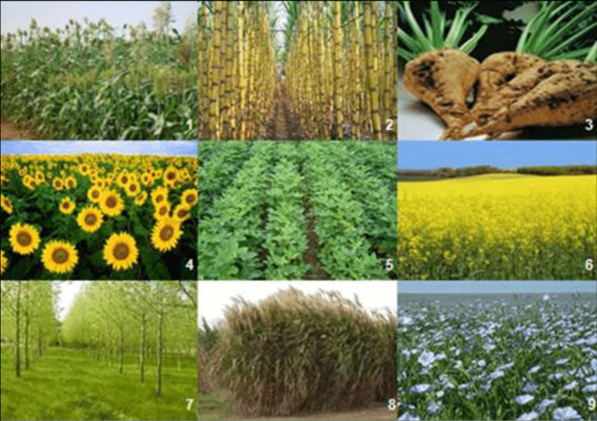
A corn stover biomass power plant is a specialized renewable energy facility designed to utilize the agricultural residues left after corn harvesting—including stalks, leaves, husks, and cobs—as a feedstock for producing electricity, heat, and biofuels, providing a sustainable solution for both energy generation and agricultural waste management. Corn stover is abundant, widely distributed across major corn-producing regions, and offers a relatively consistent chemical composition and calorific value, making it an ideal biomass resource for large-scale energy conversion. The collection, transportation, and storage of corn stover are critical aspects of plant operation, as the material is bulky, moisture-sensitive, and prone to decomposition. Preprocessing steps such as drying, grinding, chopping, and pelletization are commonly employed to reduce moisture content, improve uniformity, facilitate feeding, and enhance combustion or gasification efficiency. Proper handling and preprocessing not only ensure smooth operation but also prevent potential issues such as clogging, inconsistent energy output, or microbial degradation during storage.
Energy conversion in a corn stover biomass power plant can be accomplished through direct combustion, gasification, or co-firing with other biomass or fossil fuels, depending on feedstock availability, plant size, and desired energy products. In combustion-based systems, preprocessed corn stover is fed into boilers such as fluidized-bed, moving grate, or suspension-fired units, where it is burned to generate high-temperature flue gases. These flue gases transfer heat to water or steam circulating through boiler tubes, producing pressurized steam that drives turbines for electricity generation. Fluidized-bed boilers are particularly well-suited to corn stover, as they accommodate variability in particle size and moisture content while maintaining uniform combustion, high thermal efficiency, and minimal unburned residues. Co-firing with other biomass or fossil fuels enhances energy density, stabilizes combustion, and provides operational flexibility during periods of variable stover availability. Advanced monitoring and control systems track critical parameters such as combustion temperature, oxygen concentration, steam pressure, and flue gas composition, allowing real-time adjustments to fuel feed and airflow to optimize energy efficiency and reduce emissions.
Gasification offers an alternative high-efficiency pathway for corn stover biomass, converting the material into syngas composed of carbon monoxide, hydrogen, methane, and carbon dioxide, which can then be combusted in gas engines or turbines, or further processed into biofuels and chemicals. Gasification systems integrate syngas cleaning and conditioning equipment to remove tars, particulates, and other impurities, protecting downstream energy conversion equipment and ensuring reliable operation. Integration with combined heat and power (CHP) systems maximizes overall energy utilization by capturing waste heat from electricity generation to preheat incoming stover, dry biomass, or supply thermal energy for industrial processes or district heating networks. Seasonal storage and feedstock management strategies are critical to maintain a steady supply of corn stover, allowing the plant to operate continuously even when crop harvesting is intermittent or feedstock quality varies.
Environmental management is a key concern in corn stover biomass power plants because combustion and gasification processes can emit nitrogen oxides, sulfur oxides, particulates, and volatile organic compounds. Modern facilities employ advanced flue gas cleaning systems such as scrubbers, selective catalytic reduction units, baghouse filters, and electrostatic precipitators to minimize pollutant emissions and comply with stringent environmental regulations. Residue management is equally important; combustion produces ash rich in potassium and phosphorus, which can be returned to agricultural fields as a soil amendment, contributing to nutrient recycling and sustainable farming practices. Integration with CHP systems ensures maximum utilization of the energy content of corn stover, reducing reliance on fossil fuels, lowering greenhouse gas emissions, and improving overall plant efficiency. Automated feedstock handling, energy conversion monitoring, and residue management systems enhance operational reliability, reduce labor costs, and enable consistent renewable energy production.
Operational management of corn stover biomass power plants requires advanced automation and real-time monitoring to account for variations in moisture content, particle size, and calorific value. Dynamic control of fuel feeding, airflow, combustion temperature, and boiler pressure maintains stable energy output, prevents equipment damage, and ensures safe operation. Safety measures protect personnel and equipment from hazards associated with high-temperature combustion, pressurized steam, and handling of abrasive or corrosive ash residues. By integrating feedstock preprocessing, optimized energy conversion technologies, CHP systems, emission controls, and residue valorization, corn stover biomass power plants provide a continuous, sustainable, and environmentally responsible source of electricity, heat, and bio-products, transforming agricultural residues into valuable energy resources while supporting carbon mitigation, sustainable land management, and rural economic development.
The economic and environmental benefits of corn stover biomass power plants are significant, offering a predictable and abundant feedstock for renewable energy, reducing dependence on fossil fuels, and mitigating greenhouse gas emissions. Utilizing corn stover for energy production also addresses waste management challenges in agriculture, creating additional income streams for farmers, improving land-use efficiency, and reducing open-field burning or decomposition that can release methane or other pollutants. Modular and scalable plant designs allow deployment at both community and industrial scales, supplying electricity and thermal energy to local grids, industrial facilities, or district heating networks. By combining feedstock management, advanced energy conversion technologies, CHP integration, emission controls, and residue recycling, corn stover biomass power plants operate efficiently, sustainably, and economically, producing renewable energy and valuable by-products while fostering sustainable agriculture, circular economy practices, and long-term environmental stewardship.
A corn stover biomass power plant is a specialized renewable energy facility that converts the agricultural residues left after corn harvesting—including stalks, leaves, husks, and cobs—into electricity, heat, and biofuels, providing an effective solution for energy generation while simultaneously addressing agricultural waste management challenges. Corn stover is an abundant and widely available biomass resource in major corn-producing regions, offering a relatively consistent calorific value and chemical composition that make it suitable for large-scale biomass power generation. The collection and transportation of corn stover are critical considerations, as the material is bulky, often high in moisture content, and prone to microbial degradation during storage. To ensure efficient energy conversion, harvested stover undergoes preprocessing steps such as drying, grinding, chopping, or pelletization, which reduce moisture, standardize particle size, and improve feedstock handling and combustion behavior. Proper preprocessing not only stabilizes energy output but also prevents operational issues such as uneven combustion, slagging, or clogging in boilers or gasifiers, making it an essential step for reliable plant operation.
The energy conversion technologies used in corn stover biomass power plants are diverse and can be selected based on feedstock availability, plant size, and desired outputs. Direct combustion remains one of the most common methods, where preprocessed corn stover is fed into specialized boilers such as fluidized-bed, moving grate, or suspension-fired systems. These boilers generate high-temperature flue gases that transfer heat to water or steam circulating through boiler tubes, producing pressurized steam to drive turbines for electricity generation. Fluidized-bed boilers are particularly advantageous for corn stover because they can handle heterogeneous feedstock, maintain uniform temperature distribution, optimize combustion efficiency, and minimize unburned residues. Co-firing with other biomass types or even fossil fuels can further improve energy density, stabilize fuel supply fluctuations, and maintain continuous operation during periods of seasonal feedstock scarcity. Advanced monitoring systems track combustion parameters such as flame temperature, oxygen levels, steam pressure, and flue gas composition, enabling real-time adjustments to airflow, fuel feeding rates, and boiler conditions to maximize efficiency and minimize emissions.
Gasification is another highly efficient pathway for corn stover biomass, converting the feedstock into syngas, a mixture of carbon monoxide, hydrogen, methane, and carbon dioxide, which can be burned in gas engines or turbines to produce electricity and heat or further processed into biofuels and chemical intermediates. Gasification plants integrate syngas cleaning and conditioning equipment to remove tars, particulates, and other impurities, ensuring high operational reliability and protecting downstream machinery from fouling or corrosion. Combined heat and power (CHP) integration is common in corn stover plants, allowing waste heat from electricity generation to be utilized for preheating incoming stover, drying biomass, or supplying thermal energy to industrial processes or district heating systems. Seasonal storage and feedstock management are crucial for continuous plant operation, as corn stover harvesting is inherently seasonal and may vary in moisture content and quality, requiring careful planning to maintain a consistent fuel supply.
Environmental management is a central aspect of corn stover biomass power plants, as both combustion and gasification can release nitrogen oxides, sulfur oxides, particulates, and volatile organic compounds. Modern facilities employ advanced flue gas treatment systems, including scrubbers, selective catalytic reduction units, baghouse filters, and electrostatic precipitators, to reduce emissions and comply with strict environmental regulations. Residue management is also critical; ash generated during combustion is nutrient-rich, containing potassium and phosphorus, and can be returned to fields as a soil amendment, supporting circular nutrient cycles and sustainable farming practices. Integration with CHP systems further enhances energy efficiency by ensuring nearly all of the biomass energy is utilized for electricity and heat, reducing fossil fuel dependence and lowering greenhouse gas emissions. Automated feedstock handling, combustion monitoring, and residue management systems increase operational reliability, reduce labor costs, and enable consistent energy production even with the variability of agricultural residues.
Operational management of corn stover biomass power plants requires sophisticated automation and real-time control to handle fluctuations in moisture content, particle size, and calorific value. Dynamic adjustment of fuel feed rates, combustion air, boiler temperature, and steam pressure maintains stable energy output and prevents operational disruptions or equipment damage. Safety protocols protect personnel and equipment from high-temperature combustion hazards, pressurized steam, and handling of abrasive or corrosive ash residues. By combining optimized feedstock preprocessing, advanced energy conversion technologies, CHP integration, emissions control, and residue valorization, corn stover biomass power plants deliver a reliable, sustainable, and environmentally responsible source of renewable electricity, heat, and bio-products, transforming agricultural residues into high-value energy resources while promoting carbon mitigation, sustainable land use, and rural economic development.
The economic and environmental advantages of corn stover biomass power plants are substantial, as they provide a predictable and abundant renewable feedstock, reduce dependence on fossil fuels, and mitigate greenhouse gas emissions. Utilizing corn stover as a fuel also addresses agricultural waste management challenges, providing farmers with additional income streams, improving land-use efficiency, and minimizing environmental impacts from open-field burning or natural decomposition. Modular and scalable plant designs allow deployment from small community-based facilities integrated with local farms to large industrial-scale plants supplying electricity and heat to regional grids. By integrating feedstock management, advanced energy conversion technologies, CHP systems, emissions control, and residue recycling, corn stover biomass power plants operate efficiently, sustainably, and economically, producing renewable energy and valuable by-products while supporting sustainable agriculture, circular economy practices, and long-term environmental stewardship.
A corn stover biomass power plant is a highly specialized renewable energy facility designed to convert the agricultural residues left after corn harvesting—including stalks, leaves, husks, and cobs—into electricity, heat, and biofuels, providing a sustainable solution for both energy generation and agricultural waste management. Corn stover is abundant, widely distributed across corn-growing regions, and offers relatively uniform calorific value and chemical composition, making it an ideal feedstock for large-scale biomass power production. The successful operation of such a plant relies heavily on efficient collection, transportation, and storage of the feedstock, as corn stover is bulky, high in moisture, and susceptible to microbial degradation if not properly managed. Preprocessing steps such as drying, chopping, grinding, or pelletization are therefore essential to reduce moisture content, standardize particle size, improve fuel handling, and ensure consistent combustion or gasification performance. Proper preprocessing minimizes operational disruptions, reduces the risk of slagging or clogging in boilers, and optimizes overall energy conversion efficiency.
Energy conversion in corn stover biomass power plants is accomplished through several technologies, including direct combustion, co-firing with other biomass or fossil fuels, and gasification. In combustion-based systems, preprocessed stover is fed into boilers such as fluidized-bed, moving grate, or suspension-fired units where it is burned to produce high-temperature flue gases. These gases transfer heat to water or steam circulating in boiler tubes, generating pressurized steam that drives turbines to produce electricity. Fluidized-bed boilers are particularly advantageous for corn stover because they can handle variability in feedstock particle size and moisture content, provide uniform temperature distribution, enhance combustion efficiency, and reduce unburned residues. Co-firing with other biomass or fossil fuels enhances fuel flexibility, increases energy density, and stabilizes combustion, ensuring continuous energy production even during seasonal feedstock fluctuations. Advanced monitoring and control systems track combustion parameters such as flame temperature, oxygen levels, steam pressure, and flue gas composition, allowing real-time adjustments to optimize performance, maximize efficiency, and minimize emissions.
Gasification represents a highly efficient alternative pathway for converting corn stover into energy, where biomass is partially oxidized at high temperatures to produce syngas, a mixture of carbon monoxide, hydrogen, methane, and carbon dioxide. Syngas can be burned in gas engines or turbines to produce electricity and heat or processed further into biofuels and chemicals. Gasification systems incorporate syngas cleaning and conditioning units to remove particulates, tars, and other impurities, protecting downstream equipment and ensuring reliable operation. Integration with combined heat and power (CHP) systems enhances overall efficiency by capturing waste heat from electricity generation for preheating incoming stover, drying feedstock, or supplying thermal energy to industrial or district heating networks. Seasonal storage, careful feedstock management, and preprocessing ensure a continuous and reliable fuel supply, allowing the plant to operate year-round despite the inherently seasonal nature of corn stover harvesting.
Environmental management is a critical component of corn stover biomass power plants, as both combustion and gasification can produce emissions of nitrogen oxides, sulfur oxides, particulates, and volatile organic compounds. Modern facilities employ advanced flue gas treatment systems such as scrubbers, selective catalytic reduction units, baghouse filters, and electrostatic precipitators to minimize emissions and comply with strict environmental regulations. Residue management is equally important; the ash generated during combustion is rich in nutrients such as potassium and phosphorus and can be recycled as a soil amendment, supporting sustainable agricultural practices and circular nutrient cycles. Integration with CHP systems ensures nearly complete utilization of the energy content of corn stover, significantly reducing fossil fuel dependence and greenhouse gas emissions while improving overall plant efficiency. Automated feedstock handling, combustion monitoring, and residue management systems reduce labor requirements, increase operational reliability, and enable consistent energy production from variable feedstock.
Operational management of corn stover biomass power plants requires advanced automation and real-time control systems to manage fluctuations in moisture content, particle size, calorific value, and seasonal availability. Dynamic adjustments to fuel feed rates, combustion air, boiler temperature, and steam pressure are essential to maintain stable energy output and prevent operational disruptions or equipment damage. Safety protocols protect personnel and equipment from hazards associated with high-temperature combustion, pressurized steam, and the handling of abrasive or potentially corrosive ash residues. By integrating feedstock preprocessing, optimized energy conversion technologies, CHP systems, emission control measures, and residue valorization, corn stover biomass power plants deliver a reliable, continuous, and environmentally responsible source of electricity, heat, and bio-products. These facilities transform agricultural residues into high-value energy resources while supporting carbon mitigation, sustainable land management, and rural economic development.
The economic and environmental benefits of corn stover biomass power plants are significant, as they provide a predictable, abundant renewable feedstock, reduce reliance on fossil fuels, mitigate greenhouse gas emissions, and create additional income streams for farmers. Utilizing corn stover for energy production also addresses waste management challenges, reducing open-field burning or natural decomposition that would release methane and other pollutants into the atmosphere. Modular and scalable plant designs allow deployment at both small community levels integrated with local farms and large industrial scales supplying electricity and thermal energy to regional grids. By combining advanced feedstock management, energy conversion technologies, CHP integration, emission controls, and residue recycling, corn stover biomass power plants operate efficiently, sustainably, and economically, producing renewable energy and valuable by-products while promoting sustainable agriculture, circular economy principles, and long-term environmental stewardship.
A corn stover biomass power plant is a large-scale renewable energy facility designed to convert the abundant agricultural residues from corn harvesting—including stalks, leaves, husks, and cobs—into electricity, heat, and biofuels, providing both sustainable energy and an effective method for managing crop residues that would otherwise decompose or be burned in the field, releasing greenhouse gases. Corn stover is widely available in major corn-producing regions, with a relatively consistent chemical composition and calorific value that make it ideal for biomass power generation. Efficient collection, transportation, and storage of stover are critical, as the material is bulky, moisture-sensitive, and prone to microbial degradation if left unmanaged. Preprocessing steps such as drying, chopping, grinding, and pelletization are essential to reduce moisture content, improve feedstock uniformity, enhance handling and feeding efficiency, and ensure consistent combustion or gasification performance. These processes help prevent operational disruptions such as clogging, incomplete combustion, or slagging in boilers and enable the plant to operate reliably year-round.
Energy conversion in corn stover biomass power plants can be achieved through a variety of technologies, including direct combustion, co-firing with other biomass or fossil fuels, and thermochemical conversion through gasification. In direct combustion systems, preprocessed stover is fed into boilers such as fluidized-bed, moving grate, or suspension-fired units, generating high-temperature flue gases that transfer heat to water or steam circulating in boiler tubes to produce pressurized steam, which drives turbines for electricity generation. Fluidized-bed boilers are particularly well-suited for corn stover because they can accommodate heterogeneous feedstock with variable moisture content and particle size, maintain uniform temperature distribution, enhance combustion efficiency, and minimize unburned residues. Co-firing with other biomass types or fossil fuels improves fuel flexibility, increases energy density, and stabilizes combustion, ensuring continuous energy production despite seasonal variability in stover availability. Advanced monitoring and control systems continuously track combustion parameters such as flame temperature, oxygen concentration, steam pressure, and flue gas composition, enabling dynamic adjustments to fuel feeding rates and airflow to optimize efficiency, maximize energy recovery, and reduce emissions.
Gasification provides an alternative, high-efficiency pathway for converting corn stover into energy. In this process, biomass is partially oxidized at high temperatures to produce syngas, a mixture of carbon monoxide, hydrogen, methane, and carbon dioxide, which can be burned in gas engines or turbines to produce electricity and heat or processed further into biofuels and chemical intermediates. Gasification systems incorporate syngas cleaning and conditioning equipment to remove tars, particulates, and other contaminants, protecting downstream equipment and ensuring reliable operation. Integration with combined heat and power (CHP) systems allows the capture of waste heat from electricity generation for drying incoming stover, preheating boilers, or supplying industrial processes and district heating networks, significantly increasing overall plant efficiency. Seasonal storage, careful feedstock management, and preprocessing strategies are crucial for maintaining a continuous and reliable supply of corn stover, allowing the plant to operate year-round even with the inherent variability of agricultural harvesting schedules.
Environmental management is an integral aspect of corn stover biomass power plants, as both combustion and gasification produce emissions such as nitrogen oxides, sulfur oxides, particulates, and volatile organic compounds. Modern facilities are equipped with advanced flue gas cleaning systems, including scrubbers, selective catalytic reduction units, baghouse filters, and electrostatic precipitators, to mitigate pollutants and ensure compliance with strict environmental regulations. Residue management is equally important; ash produced during combustion is rich in nutrients such as potassium and phosphorus and can be returned to agricultural soils as a soil amendment, promoting circular nutrient cycles and sustainable farming practices. Integration with CHP or district heating systems ensures maximum utilization of the energy content of corn stover, reducing reliance on fossil fuels, minimizing greenhouse gas emissions, and improving overall plant efficiency. Automated feedstock handling, combustion control, and residue management systems enhance operational reliability, reduce labor costs, and enable continuous renewable energy production from a feedstock that is variable by nature.
Operational management of corn stover biomass power plants relies on advanced automation and real-time monitoring to manage fluctuations in moisture content, calorific value, particle size, and seasonal availability of feedstock. Dynamic adjustment of fuel feeding rates, combustion air, boiler temperature, and steam pressure is critical to maintain stable energy output, prevent equipment damage, and ensure safe operation. Safety measures protect personnel and equipment from high-temperature combustion hazards, pressurized steam, and handling of abrasive or corrosive ash residues. By integrating feedstock preprocessing, optimized energy conversion technologies, CHP systems, emission control, and residue recycling, corn stover biomass power plants provide a continuous, sustainable, and environmentally responsible source of electricity, heat, and bio-products, transforming agricultural residues into high-value energy resources while supporting carbon mitigation, sustainable land management, and rural economic development.
The economic and environmental advantages of corn stover biomass power plants are substantial, as they provide a predictable and abundant renewable feedstock, reduce reliance on fossil fuels, and mitigate greenhouse gas emissions. Using corn stover for energy production addresses agricultural waste management challenges, creating additional income streams for farmers, improving land-use efficiency, and reducing open-field burning or natural decomposition that could release methane or other pollutants. Modular and scalable plant designs allow deployment at community-level facilities integrated with local farms or large industrial-scale plants supplying electricity and heat to regional grids. By combining feedstock management, advanced energy conversion technologies, CHP integration, emission control, and residue recycling, corn stover biomass power plants operate efficiently, sustainably, and economically, producing renewable energy and valuable by-products while supporting sustainable agriculture, circular economy practices, and long-term environmental stewardship.
Sugarcane Bagasse Power Plant

A sugarcane bagasse biomass power plant is a specialized renewable energy facility designed to utilize the fibrous residue left after sugarcane stalks are crushed to extract juice, commonly known as bagasse, as a feedstock for electricity, heat, and biofuel production. Bagasse is a high-energy, fibrous material that is widely available in sugarcane-producing regions, making it an ideal biomass resource for power generation. Efficient collection, transportation, and storage are essential to maintain the quality of the bagasse, as it has relatively high moisture content immediately after crushing and is prone to microbial degradation if stored improperly. Preprocessing methods such as drying, shredding, or pelletization can be applied to improve fuel handling, standardize particle size, and enhance combustion or gasification efficiency. Proper feedstock preparation ensures smooth operation of the plant, prevents clogging or uneven combustion in boilers, and allows for a more predictable energy output.
Energy conversion in sugarcane bagasse power plants can be accomplished through multiple technologies, including direct combustion, co-firing, and gasification. In combustion systems, bagasse is burned in boilers such as bagasse-fired moving grate or fluidized-bed units, generating high-temperature flue gases that transfer heat to water or steam circulating in boiler tubes, producing pressurized steam that drives turbines for electricity generation. Fluidized-bed boilers are particularly effective in handling the variable moisture content and fibrous nature of bagasse, ensuring uniform combustion, reducing unburned residues, and enhancing thermal efficiency. Co-firing bagasse with other biomass or even fossil fuels can improve fuel flexibility, increase calorific value, and stabilize energy production during periods when bagasse supply fluctuates due to seasonal sugarcane harvest cycles. Advanced monitoring and control systems track parameters such as flame temperature, steam pressure, and oxygen levels in real time, enabling dynamic adjustments to maintain optimal combustion efficiency, maximize energy recovery, and minimize emissions.
Gasification provides an alternative high-efficiency pathway for bagasse biomass, where the material is partially oxidized at high temperatures to produce syngas composed of carbon monoxide, hydrogen, methane, and carbon dioxide. This syngas can be combusted in gas engines or turbines to generate electricity and heat or further processed into biofuels and chemical products. Gasification systems integrate syngas cleaning and conditioning units to remove particulates, tars, and other impurities, protecting downstream energy conversion equipment and ensuring stable operation. Integration with combined heat and power (CHP) systems allows the capture of waste heat for preheating incoming bagasse, drying feedstock, or supplying thermal energy to industrial processes or district heating networks, significantly improving overall energy efficiency and reducing fossil fuel dependence.
Environmental management is a critical aspect of sugarcane bagasse power plants, as both combustion and gasification can generate nitrogen oxides, sulfur oxides, particulates, and volatile organic compounds. Modern facilities utilize flue gas cleaning systems such as scrubbers, selective catalytic reduction units, baghouse filters, and electrostatic precipitators to mitigate emissions and comply with environmental regulations. Residues from combustion, particularly ash, are rich in nutrients such as potassium and phosphorus and can be recycled as a soil amendment to support sustainable agricultural practices, creating a circular nutrient cycle. Integration with CHP systems ensures maximum utilization of the energy content of bagasse, significantly improving energy efficiency, reducing greenhouse gas emissions, and minimizing waste. Automated feedstock handling, energy conversion monitoring, and residue management systems enhance operational reliability, reduce labor costs, and allow continuous energy production despite the seasonal nature of sugarcane harvesting.
Operational management of sugarcane bagasse power plants relies on sophisticated automation and real-time control systems to handle variations in moisture content, calorific value, and particle size of the feedstock. Dynamic control of fuel feeding, combustion air, boiler temperature, and steam pressure is essential to maintain stable energy output, prevent equipment damage, and ensure safe operation. Safety measures protect personnel and equipment from high-temperature combustion, pressurized steam, and handling of abrasive ash residues. By integrating feedstock preprocessing, optimized energy conversion technologies, CHP systems, emissions control, and residue valorization, sugarcane bagasse power plants provide a reliable, sustainable, and environmentally responsible source of electricity, heat, and bio-products. These facilities convert sugarcane residues into high-value energy resources while supporting carbon mitigation, sustainable land use, and economic development in sugarcane-producing regions.
The economic and environmental benefits of sugarcane bagasse biomass power plants are substantial, as they provide a predictable and abundant renewable feedstock, reduce reliance on fossil fuels, and lower greenhouse gas emissions. Using bagasse for energy production also addresses waste management challenges, creating additional income streams for sugar mills, improving land-use efficiency, and minimizing the environmental impacts of open-field burning or uncontrolled decomposition. Modular and scalable plant designs allow deployment at small community-level facilities integrated with sugarcane mills or large industrial-scale plants supplying electricity and thermal energy to regional grids. By combining feedstock management, advanced energy conversion technologies, CHP integration, emission controls, and residue recycling, sugarcane bagasse biomass power plants operate efficiently, sustainably, and economically, producing renewable energy and valuable by-products while promoting sustainable agriculture, circular economy practices, and long-term environmental stewardship.
A sugarcane bagasse biomass power plant is a renewable energy facility designed to convert the fibrous residue remaining after sugarcane juice extraction into electricity, heat, and biofuels, offering a sustainable and efficient solution for both energy generation and agricultural waste management. Bagasse is an abundant, high-energy biomass resource, particularly in regions with large-scale sugarcane cultivation, and its consistent availability during harvest seasons makes it an ideal feedstock for continuous energy production. Efficient handling of bagasse is essential, as the material is naturally moist, bulky, and prone to microbial degradation if not properly stored. Preprocessing steps such as drying, shredding, grinding, or pelletization improve its fuel quality, standardize particle size, and facilitate reliable feeding into boilers or gasifiers, ensuring stable combustion or thermochemical conversion while reducing the risk of operational disruptions, clogging, or uneven energy output.
Energy conversion in sugarcane bagasse power plants can be achieved through direct combustion, co-firing with other biomass or fossil fuels, or gasification. In direct combustion systems, bagasse is burned in boilers such as fluidized-bed, moving grate, or suspension-fired units, producing high-temperature flue gases that transfer heat to water or steam circulating in boiler tubes, generating pressurized steam to drive turbines for electricity generation. Fluidized-bed boilers are particularly suited for bagasse because they can handle its fibrous nature and variable moisture content, providing uniform combustion, minimizing unburned residues, and maximizing thermal efficiency. Co-firing bagasse with other biomass or fossil fuels improves fuel flexibility, enhances calorific value, and stabilizes plant operation, allowing continuous energy production even during periods of variable feedstock availability or seasonal fluctuations in sugarcane processing. Advanced monitoring and control systems track critical parameters such as flame temperature, oxygen concentration, steam pressure, and flue gas composition, allowing real-time adjustments to airflow, fuel feeding, and combustion conditions to maintain optimal efficiency and minimize emissions.
Gasification offers an alternative and highly efficient pathway for converting sugarcane bagasse into energy. In this process, biomass undergoes partial oxidation at high temperatures to produce syngas—a mixture of carbon monoxide, hydrogen, methane, and carbon dioxide—which can be combusted in gas engines or turbines for electricity and heat generation or further processed into biofuels and chemical intermediates. Gasification systems are equipped with syngas cleaning and conditioning technologies to remove particulates, tars, and other impurities, protecting downstream equipment and ensuring reliable operation. Integration with combined heat and power (CHP) systems enhances overall efficiency by capturing waste heat from electricity generation for drying incoming bagasse, preheating boilers, or supplying thermal energy to industrial processes or district heating networks. Seasonal storage strategies and careful feedstock management ensure a continuous supply of bagasse, enabling year-round plant operation despite the inherently seasonal nature of sugarcane harvests.
Environmental management is a key aspect of sugarcane bagasse biomass power plants, as both combustion and gasification can generate nitrogen oxides, sulfur oxides, particulates, and volatile organic compounds. Modern facilities employ advanced flue gas treatment systems such as scrubbers, selective catalytic reduction units, baghouse filters, and electrostatic precipitators to mitigate emissions and comply with strict environmental regulations. Combustion residues, particularly ash, are nutrient-rich and can be recycled as soil amendments, returning potassium, phosphorus, and other essential elements to sugarcane fields, promoting circular nutrient cycles and sustainable agricultural practices. Integration with CHP systems ensures nearly complete utilization of the energy content of bagasse, reducing reliance on fossil fuels, lowering greenhouse gas emissions, and improving overall plant efficiency. Automated feedstock handling, combustion control, and residue management systems enhance operational reliability, reduce labor requirements, and enable consistent energy production even when feedstock characteristics vary.
Operational management of sugarcane bagasse biomass power plants relies on sophisticated automation and real-time monitoring to handle fluctuations in moisture content, calorific value, particle size, and seasonal feedstock availability. Dynamic control of fuel feeding, combustion air, boiler temperature, and steam pressure maintains stable energy output, prevents equipment damage, and ensures safe plant operation. Safety systems protect personnel and equipment from hazards associated with high-temperature combustion, pressurized steam, and handling abrasive or potentially corrosive ash residues. By integrating feedstock preprocessing, optimized energy conversion technologies, CHP systems, emissions control, and residue recycling, sugarcane bagasse biomass power plants provide a continuous, reliable, and environmentally responsible source of electricity, heat, and bio-products, transforming sugarcane residues into high-value energy resources while supporting carbon mitigation, sustainable land use, and rural economic development.
The economic and environmental benefits of sugarcane bagasse biomass power plants are substantial, as they provide a predictable, abundant renewable feedstock, reduce dependence on fossil fuels, and mitigate greenhouse gas emissions. Utilizing bagasse for energy production also addresses agricultural waste management challenges, creating additional income streams for sugar mills, improving land-use efficiency, and minimizing open-field burning or decomposition that would otherwise release methane and other pollutants. Modular and scalable plant designs allow deployment at small community-level facilities integrated with sugarcane mills or at large industrial-scale plants supplying electricity and thermal energy to regional grids. By combining feedstock management, advanced energy conversion technologies, CHP integration, emissions control, and residue recycling, sugarcane bagasse biomass power plants operate efficiently, sustainably, and economically, producing renewable energy and valuable by-products while promoting sustainable agriculture, circular economy practices, and long-term environmental stewardship.
A sugarcane bagasse biomass power plant is a renewable energy facility that converts the fibrous residue remaining after sugarcane processing into electricity, heat, and biofuels, effectively transforming a by-product that would otherwise pose disposal challenges into a valuable energy resource. Bagasse is abundant in regions with extensive sugarcane cultivation, and its fibrous structure, moderate moisture content, and relatively high calorific value make it highly suitable for biomass energy applications. Efficient handling of bagasse is crucial because the material is bulky, moist, and prone to microbial degradation if left in open storage. Preprocessing techniques such as drying, shredding, grinding, or pelletization are applied to reduce moisture content, standardize particle size, improve feedstock flow, and enhance combustion or gasification performance. These steps ensure consistent fuel quality, smooth plant operation, and predictable energy output while minimizing issues such as boiler fouling, slagging, or uneven combustion.
Energy conversion in sugarcane bagasse biomass power plants can be achieved through direct combustion, co-firing with other biomass or fossil fuels, and gasification, depending on the specific plant design and energy goals. In direct combustion systems, bagasse is burned in boilers such as fluidized-bed, moving grate, or suspension-fired units, generating high-temperature flue gases that transfer heat to water or steam circulating in boiler tubes, producing pressurized steam that drives turbines for electricity generation. Fluidized-bed boilers are particularly effective for bagasse due to their ability to handle fibrous, heterogeneous feedstock with variable moisture content, maintain uniform combustion, minimize unburned residues, and maximize thermal efficiency. Co-firing bagasse with other biomass or fossil fuels enhances fuel flexibility, increases calorific value, and stabilizes energy production during periods of variable bagasse availability, particularly outside of the sugarcane harvest season. Advanced monitoring and control systems continuously track parameters such as flame temperature, oxygen levels, steam pressure, and flue gas composition, allowing real-time adjustments to optimize combustion efficiency, energy output, and emission levels.
Gasification provides an alternative pathway for converting bagasse into energy with high efficiency. In this process, the biomass undergoes partial oxidation at elevated temperatures to produce syngas, a mixture of carbon monoxide, hydrogen, methane, and carbon dioxide, which can be combusted in gas engines or turbines to generate electricity and heat or further processed into biofuels and chemical products. Gasification systems include syngas cleaning and conditioning units to remove tars, particulates, and other contaminants, ensuring the protection of downstream equipment and maintaining stable operation. Integration with combined heat and power (CHP) systems significantly increases overall plant efficiency by capturing waste heat from electricity generation for drying incoming bagasse, preheating boilers, or supplying thermal energy to industrial processes and district heating networks. Seasonal storage and feedstock management strategies are essential to ensure a continuous fuel supply, allowing the plant to operate efficiently year-round despite the inherently seasonal nature of sugarcane harvesting.
Environmental management is a key focus for sugarcane bagasse power plants because combustion and gasification processes can produce nitrogen oxides, sulfur oxides, particulate matter, and volatile organic compounds. Modern facilities are equipped with advanced flue gas cleaning technologies such as scrubbers, selective catalytic reduction units, baghouse filters, and electrostatic precipitators to mitigate emissions and comply with environmental regulations. Combustion residues, especially ash, are nutrient-rich and can be returned to sugarcane fields as soil amendments, providing potassium, phosphorus, and other essential nutrients, supporting circular nutrient cycles and sustainable agricultural practices. The integration of CHP systems maximizes energy utilization, ensuring that nearly all the energy content of bagasse is effectively harnessed for electricity and heat, reducing fossil fuel consumption and lowering greenhouse gas emissions. Automated systems for feedstock handling, energy conversion monitoring, and residue management enhance operational reliability, reduce labor requirements, and enable consistent energy production even with variations in feedstock characteristics.
Operational management of sugarcane bagasse biomass power plants relies on sophisticated automation and real-time monitoring systems to address variations in feedstock moisture content, calorific value, particle size, and seasonal availability. Dynamic control of fuel feeding, combustion air, boiler temperature, and steam pressure is critical for maintaining stable energy output, preventing equipment damage, and ensuring safe operation. Safety measures protect plant personnel and equipment from hazards associated with high-temperature combustion, pressurized steam, and handling abrasive or corrosive ash residues. By integrating feedstock preprocessing, optimized energy conversion technologies, CHP systems, emission control, and residue recycling, sugarcane bagasse biomass power plants provide a continuous, reliable, and environmentally responsible source of electricity, heat, and bio-products, transforming sugarcane residues into high-value energy resources while promoting carbon mitigation, sustainable land use, and economic development in sugarcane-producing regions.
The economic and environmental advantages of sugarcane bagasse biomass power plants are significant, as they provide a predictable and abundant renewable feedstock, reduce dependence on fossil fuels, mitigate greenhouse gas emissions, and address agricultural waste management challenges. Utilizing bagasse for energy production creates additional revenue streams for sugar mills, improves land-use efficiency, and reduces open-field burning or uncontrolled decomposition, which could release methane and other pollutants. Modular and scalable plant designs allow deployment at small-scale facilities integrated with sugar mills or at large industrial-scale plants supplying electricity and thermal energy to regional grids. By combining advanced feedstock management, energy conversion technologies, CHP integration, emission controls, and residue recycling, sugarcane bagasse biomass power plants operate efficiently, sustainably, and economically, producing renewable energy and valuable by-products while supporting sustainable agriculture, circular economy practices, and long-term environmental stewardship.
A sugarcane bagasse biomass power plant is a renewable energy facility designed to harness the fibrous residue left over from sugarcane juice extraction and convert it into electricity, heat, and other forms of energy, transforming what is otherwise an agricultural waste by-product into a reliable and valuable energy source. Bagasse is abundant in sugarcane-producing regions and possesses a high calorific value, making it a suitable biomass feedstock for continuous energy generation. However, its natural high moisture content and fibrous texture require careful handling, storage, and preprocessing to ensure stable operation. Techniques such as drying, shredding, grinding, and pelletization are employed to reduce moisture, standardize particle size, and improve fuel handling, feeding, and combustion efficiency. Proper preprocessing is essential to prevent operational issues like clogging, uneven combustion, or boiler fouling and to enable predictable and efficient energy output.
Energy conversion in sugarcane bagasse biomass power plants can be carried out through direct combustion, co-firing with other fuels, or gasification, depending on the plant design and energy goals. In direct combustion systems, bagasse is burned in boilers such as moving grate, fluidized-bed, or suspension-fired units, generating high-temperature flue gases that heat water or steam in boiler tubes, producing pressurized steam to drive turbines for electricity generation. Fluidized-bed boilers are especially suitable for bagasse because they handle the fibrous, heterogeneous feedstock effectively, maintain uniform combustion, reduce unburned residues, and maximize thermal efficiency. Co-firing with other biomass or fossil fuels increases fuel flexibility, stabilizes combustion, and allows continuous energy production even when bagasse supply fluctuates due to seasonal harvesting cycles. Advanced monitoring and control systems track parameters such as flame temperature, oxygen concentration, steam pressure, and flue gas composition, enabling real-time adjustments that optimize combustion efficiency, energy recovery, and emissions performance.
Gasification provides a high-efficiency alternative for converting bagasse into energy, where the biomass undergoes partial oxidation at elevated temperatures to produce syngas—a mixture of carbon monoxide, hydrogen, methane, and carbon dioxide. Syngas can then be combusted in gas engines or turbines to produce electricity and heat, or processed further into biofuels and chemical products. Gasification systems incorporate syngas cleaning and conditioning units to remove tars, particulates, and other impurities, protecting downstream equipment and maintaining stable operations. Integration with combined heat and power (CHP) systems enhances overall efficiency by utilizing waste heat from electricity generation for drying incoming bagasse, preheating boilers, or supplying thermal energy to industrial processes or district heating networks. Careful feedstock management and seasonal storage strategies are essential to ensure a steady supply of bagasse, enabling year-round plant operation despite the seasonal nature of sugarcane cultivation.
Environmental management is a critical component of sugarcane bagasse biomass power plants, as combustion and gasification processes can generate nitrogen oxides, sulfur oxides, particulate matter, and volatile organic compounds. Modern facilities employ advanced flue gas treatment technologies, including scrubbers, selective catalytic reduction units, baghouse filters, and electrostatic precipitators, to minimize emissions and comply with stringent environmental standards. Combustion residues, particularly ash, are rich in nutrients such as potassium and phosphorus and can be returned to sugarcane fields as a soil amendment, supporting sustainable farming practices and circular nutrient cycles. Integration with CHP systems ensures maximum utilization of bagasse energy content, reducing reliance on fossil fuels, lowering greenhouse gas emissions, and improving overall plant efficiency. Automated feedstock handling, combustion monitoring, and residue management systems enhance operational reliability, reduce labor requirements, and enable consistent energy production despite variations in feedstock quality and seasonal availability.
Operational management of sugarcane bagasse biomass power plants relies on sophisticated automation and real-time monitoring systems to manage variability in feedstock moisture content, calorific value, particle size, and seasonal availability. Dynamic adjustments to fuel feeding rates, combustion air supply, boiler temperature, and steam pressure are critical for maintaining stable energy output, preventing equipment damage, and ensuring safe operations. Safety systems protect personnel and equipment from hazards associated with high-temperature combustion, pressurized steam, and handling abrasive or potentially corrosive ash residues. By integrating feedstock preprocessing, optimized energy conversion technologies, CHP systems, emissions control, and residue valorization, sugarcane bagasse biomass power plants provide a continuous, reliable, and environmentally responsible source of electricity, heat, and bio-products, converting sugarcane residues into high-value energy while promoting carbon mitigation, sustainable land use, and economic development in sugarcane-producing regions.
The economic and environmental benefits of sugarcane bagasse biomass power plants are considerable. They offer a predictable and abundant renewable feedstock, reduce dependence on fossil fuels, mitigate greenhouse gas emissions, and provide a solution for agricultural residue management. Utilizing bagasse for energy production creates additional revenue streams for sugar mills, enhances land-use efficiency, and prevents open-field burning or uncontrolled decomposition that would release methane and other pollutants. Modular and scalable plant designs allow deployment at community-level facilities integrated with sugar mills or at industrial-scale plants supplying electricity and thermal energy to regional grids. By combining advanced feedstock handling, energy conversion technologies, CHP integration, emission controls, and residue recycling, sugarcane bagasse biomass power plants operate efficiently, sustainably, and economically, generating renewable energy and valuable by-products while supporting sustainable agriculture, circular economy principles, and long-term environmental stewardship.
Rice Husk Biomass Power Plant
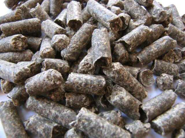
A rice husk biomass power plant is a renewable energy facility that converts the outer shell of rice grains, known as rice husk, into electricity, heat, and bio-products, providing an efficient way to utilize an agricultural by-product that is often considered waste. Rice husk is a highly abundant residue in rice-producing regions and is characterized by its low bulk density, relatively high silica content, and moderate calorific value, which make it suitable for combustion, gasification, or pyrolysis processes. Efficient collection, transportation, and storage of rice husk are crucial because it is bulky, lightweight, and prone to spontaneous combustion if accumulated improperly. Preprocessing methods such as drying, briquetting, or pelletization are often employed to improve fuel density, standardize particle size, and enhance handling and feeding performance, ensuring stable and predictable energy conversion while minimizing operational issues such as uneven combustion, ash accumulation, or boiler fouling.
Energy conversion in rice husk biomass power plants can be achieved through direct combustion, co-firing with other biomass or fossil fuels, or gasification, depending on the plant design and intended energy output. In direct combustion systems, rice husk is burned in specially designed boilers such as fluidized-bed, suspension-fired, or moving grate units, producing high-temperature flue gases that transfer heat to water or steam circulating in boiler tubes, generating pressurized steam to drive turbines for electricity production. Fluidized-bed boilers are particularly effective for rice husk because they can handle the low bulk density and heterogeneous nature of the material, provide uniform combustion, reduce unburned residues, and maximize thermal efficiency. Co-firing rice husk with other biomass or fossil fuels enhances fuel flexibility, stabilizes combustion, and allows continuous energy generation during periods of variable husk availability, which is often influenced by the seasonal rice harvesting cycles. Advanced monitoring and control systems track critical parameters such as flame temperature, oxygen levels, steam pressure, and flue gas composition, allowing real-time adjustments to optimize combustion efficiency, maximize energy recovery, and minimize emissions.
Gasification is another efficient pathway for rice husk biomass energy, converting the husk into syngas—a mixture of carbon monoxide, hydrogen, methane, and carbon dioxide—through partial oxidation at high temperatures. The syngas can be combusted in gas engines or turbines to produce electricity and heat, or further processed into biofuels and chemicals. Rice husk gasification systems integrate syngas cleaning and conditioning equipment to remove particulates, tars, and other impurities, ensuring reliable operation and protecting downstream machinery. Combined heat and power (CHP) integration is common in rice husk plants, allowing waste heat from electricity generation to be reused for drying incoming husk, preheating boilers, or supplying thermal energy to industrial processes or district heating networks. Seasonal storage strategies and careful feedstock management are critical for maintaining a continuous supply of rice husk, enabling year-round operation despite the inherently seasonal nature of rice cultivation.
Environmental management is a central concern for rice husk biomass power plants because combustion and gasification can generate nitrogen oxides, sulfur oxides, particulate matter, and volatile organic compounds. Modern plants utilize advanced flue gas cleaning systems such as electrostatic precipitators, baghouse filters, scrubbers, and selective catalytic reduction units to mitigate emissions and comply with stringent environmental regulations. Combustion residues, particularly ash, are rich in silica and other trace minerals and can be used in construction materials, soil amendments, or as a filler in industrial applications, promoting circular economy practices and reducing waste disposal issues. CHP systems maximize energy utilization by capturing waste heat from electricity generation for secondary uses, improving overall plant efficiency, reducing fossil fuel dependence, and lowering greenhouse gas emissions. Automated feedstock handling, combustion monitoring, and residue management systems enhance operational reliability, reduce labor costs, and ensure consistent energy production even when feedstock characteristics vary.
Operational management of rice husk biomass power plants requires sophisticated automation and real-time monitoring systems to handle fluctuations in moisture content, calorific value, and particle size of the husk. Dynamic control of fuel feeding rates, combustion air supply, boiler temperature, and steam pressure is critical to maintain stable energy output, prevent equipment damage, and ensure safe operation. Safety systems protect personnel and equipment from hazards associated with high-temperature combustion, pressurized steam, and handling of abrasive or silica-rich ash residues. By integrating feedstock preprocessing, optimized energy conversion technologies, CHP systems, emissions control, and residue valorization, rice husk biomass power plants provide a continuous, reliable, and environmentally responsible source of electricity, heat, and bio-products, transforming agricultural residues into high-value energy resources while supporting carbon mitigation, sustainable land management, and rural economic development.
The economic and environmental benefits of rice husk biomass power plants are significant, as they provide a readily available renewable feedstock, reduce reliance on fossil fuels, mitigate greenhouse gas emissions, and address agricultural residue management challenges. Using rice husk for energy production creates additional income for rice mills, reduces open-field burning or decomposition that would release methane, and promotes more sustainable agricultural practices. Modular and scalable plant designs allow deployment at community-scale facilities integrated with rice milling operations or at large industrial-scale plants supplying electricity and thermal energy to regional grids. By combining feedstock management, advanced energy conversion technologies, CHP integration, emission controls, and residue utilization, rice husk biomass power plants operate efficiently, sustainably, and economically, producing renewable energy and valuable by-products while supporting circular economy principles, sustainable agriculture, and long-term environmental stewardship.
A rice husk biomass power plant is a renewable energy facility that transforms the outer shell of rice grains, known as husk, into electricity, heat, and other usable forms of energy, providing a sustainable solution for managing agricultural residues that would otherwise be wasted or contribute to environmental pollution. Rice husk is highly abundant in rice-producing regions and is characterized by its fibrous structure, low bulk density, and moderate calorific value, making it suitable for combustion, gasification, or pyrolysis-based energy generation. Effective collection, transportation, and storage of rice husk are critical to maintain its quality and prevent spontaneous combustion, as the material is lightweight, prone to microbial degradation, and easily dispersed. Preprocessing methods such as drying, grinding, pelletization, or briquetting enhance its energy density, standardize particle size, and improve feeding and combustion performance, ensuring reliable and consistent energy conversion while reducing operational issues like uneven burning, ash accumulation, or boiler fouling.
Energy conversion in rice husk biomass power plants can be accomplished through direct combustion, co-firing with other biomass or fossil fuels, and gasification depending on the plant’s design and energy objectives. In direct combustion systems, rice husk is burned in boilers such as fluidized-bed, moving grate, or suspension-fired units, producing high-temperature flue gases that heat water or steam circulating in boiler tubes, generating pressurized steam to drive turbines for electricity production. Fluidized-bed boilers are particularly effective for rice husk due to their ability to handle the low bulk density, fibrous nature, and moisture variability of the material, ensuring uniform combustion, reducing unburned residues, and maximizing thermal efficiency. Co-firing rice husk with other fuels enhances energy density, stabilizes combustion, and allows continuous energy production even when husk availability fluctuates due to seasonal rice harvesting patterns. Advanced automation and monitoring systems track critical parameters such as flame temperature, oxygen levels, steam pressure, and flue gas composition, enabling real-time adjustments that optimize energy output, improve efficiency, and minimize emissions.
Gasification offers an alternative, high-efficiency pathway for rice husk biomass energy production, converting the husk into syngas through partial oxidation at elevated temperatures. The syngas, which contains carbon monoxide, hydrogen, methane, and carbon dioxide, can be combusted in gas engines or turbines to generate electricity and heat, or processed further into biofuels and chemical products. Gasification systems incorporate syngas cleaning and conditioning technologies to remove particulates, tars, and other impurities, protecting downstream equipment and ensuring stable and continuous operation. Integration with combined heat and power (CHP) systems further enhances overall efficiency by capturing waste heat from electricity generation for drying incoming rice husk, preheating boilers, or supplying thermal energy to industrial processes or district heating networks. Careful feedstock management and seasonal storage strategies are essential to maintain a continuous supply of rice husk, enabling the plant to operate effectively year-round despite the seasonal nature of rice production.
Environmental management is a critical aspect of rice husk biomass power plants, as combustion and gasification can generate nitrogen oxides, sulfur oxides, particulate matter, and volatile organic compounds. Modern facilities utilize flue gas cleaning technologies such as baghouse filters, electrostatic precipitators, scrubbers, and selective catalytic reduction units to reduce emissions and meet stringent environmental standards. Ash residues produced during combustion are rich in silica and trace minerals, making them suitable for use in construction materials, soil amendments, or industrial fillers, promoting circular economy practices and reducing waste disposal issues. CHP integration ensures nearly complete utilization of the energy content of rice husk, lowering fossil fuel consumption, reducing greenhouse gas emissions, and improving overall plant efficiency. Automated feedstock handling, combustion control, and residue management systems improve operational reliability, reduce labor requirements, and ensure stable energy production despite variations in husk quality, moisture content, and seasonal availability.
Operational management of rice husk biomass power plants requires advanced automation and real-time monitoring to handle fluctuations in feedstock moisture, calorific value, and particle size. Dynamic adjustments of fuel feed rates, combustion air, boiler temperature, and steam pressure are critical for maintaining stable electricity and heat output, preventing equipment damage, and ensuring safety. Safety systems protect plant personnel and equipment from hazards associated with high-temperature combustion, pressurized steam, and the handling of abrasive or silica-rich ash residues. By integrating feedstock preprocessing, optimized energy conversion technologies, CHP systems, emissions control, and residue recycling, rice husk biomass power plants deliver a continuous, reliable, and environmentally responsible source of electricity, heat, and bio-products, turning agricultural residues into high-value energy resources while supporting carbon mitigation, sustainable land use, and rural economic development.
The economic and environmental benefits of rice husk biomass power plants are substantial. They provide an abundant and predictable renewable feedstock, reduce dependence on fossil fuels, mitigate greenhouse gas emissions, and address the challenge of agricultural residue management. Utilizing rice husk for energy production generates additional income for rice mills, reduces open-field burning or uncontrolled decomposition that would release methane, and supports more sustainable agricultural practices. Modular and scalable plant designs allow deployment at small-scale facilities integrated with rice milling operations or at large industrial-scale plants supplying electricity and thermal energy to regional grids. By combining advanced feedstock management, efficient energy conversion technologies, CHP integration, emission controls, and ash utilization, rice husk biomass power plants operate efficiently, sustainably, and economically, producing renewable energy and valuable by-products while promoting circular economy practices, sustainable agriculture, and long-term environmental stewardship.
A rice husk biomass power plant is a sophisticated renewable energy facility that converts the fibrous outer shells of rice grains, commonly called rice husk, into electricity, heat, and other forms of energy, turning what is traditionally considered agricultural waste into a valuable resource. Rice husk is produced in large quantities in rice-growing regions and contains a moderate calorific value along with a high silica content, characteristics that influence both its energy potential and the design requirements for energy conversion systems. Proper collection, storage, and handling are crucial, as rice husk is lightweight, bulky, and prone to microbial degradation or spontaneous combustion if stored improperly. Preprocessing techniques such as drying, grinding, pelletization, or briquetting are often used to increase energy density, standardize particle size, and improve feedstock flow into boilers or gasifiers. These measures ensure consistent combustion or gasification, minimize operational issues such as clogging or uneven burning, and allow the plant to maintain steady energy production throughout the year.
Energy conversion in rice husk biomass power plants can be achieved through direct combustion, co-firing with other fuels, or gasification, each offering unique advantages depending on plant scale, energy demands, and feedstock availability. In direct combustion systems, rice husk is burned in specially designed boilers such as moving grate, fluidized-bed, or suspension-fired units, producing high-temperature flue gases that transfer heat to water or steam circulating in boiler tubes, generating pressurized steam for electricity production. Fluidized-bed boilers are particularly effective for rice husk because they accommodate its low bulk density and heterogeneous composition, promote uniform combustion, reduce unburned residues, and maximize thermal efficiency. Co-firing rice husk with other biomass or fossil fuels enhances energy density, stabilizes combustion, and ensures uninterrupted power generation during periods when rice husk supply is limited or variable due to seasonal harvesting cycles. Advanced control and monitoring systems track flame temperature, oxygen levels, steam pressure, and flue gas composition in real time, enabling precise adjustments to maintain optimal energy output, fuel efficiency, and emissions compliance.
Gasification represents an alternative and highly efficient pathway for rice husk utilization, in which the biomass is partially oxidized at elevated temperatures to produce syngas—a mixture of carbon monoxide, hydrogen, methane, and carbon dioxide—which can then be combusted in gas engines or turbines for electricity and heat generation or further refined into biofuels and chemical products. Gasification systems are equipped with syngas cleaning and conditioning equipment to remove tars, particulates, and other contaminants, ensuring reliable downstream operation and preventing equipment damage. Integration with combined heat and power (CHP) systems allows the recovery of waste heat from electricity generation for drying incoming rice husk, preheating boilers, or providing thermal energy to industrial processes or district heating networks, significantly increasing overall plant efficiency. Seasonal storage and feedstock management strategies are critical for maintaining a steady supply of rice husk, enabling the plant to operate year-round despite the seasonal nature of rice cultivation.
Environmental management is a central focus for rice husk biomass power plants, as combustion and gasification processes can emit nitrogen oxides, sulfur oxides, particulate matter, and volatile organic compounds. Modern plants employ flue gas cleaning technologies such as electrostatic precipitators, baghouse filters, scrubbers, and selective catalytic reduction systems to minimize emissions and comply with stringent environmental regulations. Combustion residues, particularly ash, are rich in silica and other minerals and can be used in construction materials, as soil amendments, or as industrial fillers, promoting sustainable waste management and circular economy practices. CHP integration ensures near-total utilization of the energy content of rice husk, reducing reliance on fossil fuels, lowering greenhouse gas emissions, and improving overall plant efficiency. Automated feedstock handling, combustion monitoring, and ash management systems enhance operational reliability, reduce labor requirements, and maintain consistent energy production even when the characteristics of rice husk vary in moisture content, calorific value, or particle size.
Operational management of rice husk biomass power plants relies heavily on advanced automation and real-time monitoring to address fluctuations in feedstock quality, particle size, and seasonal availability. Dynamic control of fuel feeding rates, combustion air, boiler temperature, and steam pressure is critical to ensure steady electricity and heat output, prevent equipment damage, and maintain safe operations. Safety systems protect plant personnel and equipment from hazards associated with high-temperature combustion, pressurized steam, and handling abrasive or silica-rich ash residues. By integrating feedstock preprocessing, optimized energy conversion technologies, CHP systems, emissions control, and residue valorization, rice husk biomass power plants deliver a continuous, reliable, and environmentally responsible source of electricity, heat, and bio-products, transforming agricultural residues into high-value energy resources while supporting carbon mitigation, sustainable land use, and rural economic development.
The economic and environmental benefits of rice husk biomass power plants are significant, providing a renewable, abundant, and predictable feedstock that reduces dependency on fossil fuels, mitigates greenhouse gas emissions, and offers a solution for agricultural residue management. Using rice husk for energy generation creates additional revenue streams for rice mills, reduces open-field burning or uncontrolled decomposition that could release methane, and encourages sustainable farming practices. Modular and scalable plant designs enable deployment at small-scale facilities integrated with rice milling operations or at industrial-scale plants supplying electricity and thermal energy to regional grids. By combining efficient feedstock management, advanced energy conversion technologies, CHP integration, emission control, and ash utilization, rice husk biomass power plants operate efficiently, sustainably, and economically, producing renewable energy and valuable by-products while supporting circular economy practices, sustainable agriculture, and long-term environmental stewardship.
A rice husk biomass power plant is a renewable energy facility designed to convert rice husks, the fibrous outer shells of rice grains, into electricity, heat, and other forms of energy, transforming an abundant agricultural by-product that would otherwise require disposal into a valuable energy resource. Rice husk is produced in large quantities in rice-growing regions and contains a moderate calorific value and high silica content, which makes it both a suitable fuel for energy generation and a challenging material to handle due to its abrasive nature and low bulk density. Effective collection, transportation, and storage are essential to prevent moisture accumulation, microbial degradation, or spontaneous combustion. Preprocessing methods, including drying, grinding, pelletization, or briquetting, are commonly applied to increase energy density, improve fuel uniformity, facilitate smooth feeding into boilers or gasifiers, and optimize combustion or gasification performance. Proper handling and preparation of rice husk feedstock ensure consistent energy output, reduce operational problems such as uneven burning or boiler fouling, and improve overall plant reliability.
Energy conversion in rice husk biomass power plants can be achieved through direct combustion, co-firing with other fuels, or gasification, depending on the plant design, scale, and intended energy output. In direct combustion systems, rice husk is burned in specially designed boilers such as moving grate, fluidized-bed, or suspension-fired units, generating high-temperature flue gases that transfer heat to water or steam circulating in boiler tubes, producing pressurized steam for driving turbines and generating electricity. Fluidized-bed boilers are particularly suitable for rice husk because they can handle the material’s low bulk density, fibrous structure, and variable moisture content, ensuring uniform combustion, minimizing unburned residues, and maximizing thermal efficiency. Co-firing rice husk with other biomass or fossil fuels enhances energy density, stabilizes combustion, and allows continuous energy production even when husk supply fluctuates due to seasonal rice harvest cycles. Advanced monitoring and automation systems track parameters such as flame temperature, oxygen concentration, steam pressure, and flue gas composition, enabling real-time adjustments to optimize energy output, combustion efficiency, and emissions control.
Gasification provides an alternative, highly efficient pathway for converting rice husk into energy. In this process, the biomass undergoes partial oxidation at high temperatures to produce syngas, a mixture of carbon monoxide, hydrogen, methane, and carbon dioxide, which can be combusted in gas engines or turbines for electricity and heat production, or further processed into biofuels and chemical intermediates. Gasification systems include syngas cleaning and conditioning equipment to remove tars, particulates, and other impurities, protecting downstream equipment and ensuring stable, reliable operation. Integration with combined heat and power (CHP) systems allows recovery of waste heat from electricity generation for drying incoming husk, preheating boilers, or supplying thermal energy to industrial processes or district heating networks, significantly improving overall plant efficiency. Effective seasonal storage and feedstock management strategies ensure a continuous supply of rice husk, enabling year-round operation despite the inherently seasonal nature of rice cultivation.
Environmental management is a critical aspect of rice husk biomass power plants because combustion and gasification processes can generate nitrogen oxides, sulfur oxides, particulate matter, and volatile organic compounds. Modern plants are equipped with advanced flue gas cleaning technologies, including electrostatic precipitators, baghouse filters, scrubbers, and selective catalytic reduction units, to minimize emissions and comply with strict environmental regulations. Combustion residues, particularly ash, are rich in silica and trace minerals, making them valuable for use in construction materials, soil amendments, or industrial fillers, promoting circular economy practices and reducing waste disposal challenges. CHP integration ensures nearly complete utilization of the energy content of rice husk, lowering fossil fuel consumption, reducing greenhouse gas emissions, and improving overall plant efficiency. Automated feedstock handling, combustion monitoring, and residue management systems enhance operational reliability, reduce labor requirements, and maintain consistent energy production even with variability in husk moisture content, calorific value, and particle size.
Operational management of rice husk biomass power plants relies on sophisticated automation and real-time monitoring to accommodate variations in feedstock quality, particle size, and seasonal availability. Dynamic control of fuel feeding rates, combustion air supply, boiler temperature, and steam pressure is essential for maintaining steady electricity and heat output, preventing equipment damage, and ensuring safe operation. Safety systems protect personnel and equipment from hazards associated with high-temperature combustion, pressurized steam, and the handling of abrasive or silica-rich ash residues. By integrating feedstock preprocessing, advanced energy conversion technologies, CHP systems, emissions control, and residue valorization, rice husk biomass power plants provide a continuous, reliable, and environmentally responsible source of electricity, heat, and bio-products, transforming agricultural residues into high-value energy resources while supporting carbon mitigation, sustainable land management, and rural economic development.
The economic and environmental benefits of rice husk biomass power plants are considerable, as they provide a renewable, abundant, and predictable feedstock, reduce reliance on fossil fuels, mitigate greenhouse gas emissions, and offer a solution for agricultural residue management. Using rice husk for energy production creates additional income for rice mills, reduces open-field burning or uncontrolled decomposition that would release methane, and encourages sustainable farming practices. Modular and scalable plant designs enable deployment at small-scale facilities integrated with rice milling operations or at industrial-scale plants supplying electricity and thermal energy to regional grids. By combining efficient feedstock management, advanced energy conversion technologies, CHP integration, emissions control, and ash utilization, rice husk biomass power plants operate efficiently, sustainably, and economically, producing renewable energy and valuable by-products while supporting circular economy principles, sustainable agriculture, and long-term environmental stewardship.
Wood Biomass Power Plant
A wood biomass power plant is a renewable energy facility designed to convert wood residues, including sawdust, wood chips, bark, branches, and other forestry or sawmill by-products, into electricity, heat, and other usable energy forms, transforming what would otherwise be waste material into a valuable and sustainable resource. Wood biomass is abundant in regions with forestry and wood-processing industries, offering a reliable feedstock with relatively high energy content and predictable availability. Effective collection, transportation, and storage are essential because wood biomass can vary in moisture content, particle size, and density, and improper handling can lead to microbial degradation, spontaneous combustion, or uneven feeding into boilers or gasifiers. Preprocessing methods such as drying, chipping, grinding, pelletizing, or briquetting are commonly employed to increase energy density, standardize particle size, improve fuel flow, and enhance combustion or gasification efficiency. These steps ensure stable and efficient energy conversion, reduce operational problems such as boiler fouling or slag formation, and improve overall plant reliability and safety.
Energy conversion in wood biomass power plants can be achieved through direct combustion, co-firing with other fuels, or gasification, each suited to different plant sizes, feedstock types, and energy demands. In direct combustion systems, wood biomass is burned in boilers such as moving grate, fluidized-bed, or suspension-fired units, producing high-temperature flue gases that transfer heat to water or steam circulating in boiler tubes, generating pressurized steam to drive turbines for electricity production. Fluidized-bed boilers are particularly effective for wood biomass because they can handle heterogeneous, fibrous, and variable-moisture feedstock, ensuring uniform combustion, reducing unburned residues, and maximizing thermal efficiency. Co-firing wood biomass with other fuels enhances energy density, stabilizes combustion, and allows continuous operation even when wood residue supply fluctuates due to seasonal forestry or sawmill activities. Advanced automation and monitoring systems track flame temperature, oxygen concentration, steam pressure, and flue gas composition, allowing precise real-time adjustments to optimize energy output, combustion efficiency, and emissions compliance.
Gasification provides an alternative, high-efficiency route for wood biomass energy production, in which the feedstock undergoes partial oxidation at elevated temperatures to produce syngas—a mixture of carbon monoxide, hydrogen, methane, and carbon dioxide—that can be combusted in gas engines or turbines to generate electricity and heat, or processed further into biofuels and chemical products. Gasification systems are equipped with syngas cleaning and conditioning equipment to remove tars, particulates, and other impurities, protecting downstream machinery and ensuring reliable operation. Integration with combined heat and power (CHP) systems significantly improves overall efficiency by capturing waste heat from electricity generation for drying incoming wood biomass, preheating boilers, or supplying thermal energy to industrial processes or district heating networks. Seasonal storage strategies and careful feedstock management are critical to ensure a steady and continuous supply of wood residues, enabling year-round plant operation despite variations in availability or moisture content.
Environmental management is a central concern for wood biomass power plants because combustion and gasification can produce nitrogen oxides, sulfur oxides, particulate matter, and volatile organic compounds. Modern facilities employ advanced flue gas cleaning technologies, including baghouse filters, electrostatic precipitators, scrubbers, and selective catalytic reduction units, to minimize emissions and comply with strict environmental standards. Combustion residues such as ash are rich in minerals like calcium, potassium, and phosphorus and can be used in construction materials, soil amendments, or as industrial fillers, promoting circular economy practices and reducing waste disposal challenges. CHP integration ensures nearly complete utilization of the energy content of wood biomass, lowering fossil fuel consumption, reducing greenhouse gas emissions, and improving overall plant efficiency. Automated feedstock handling, combustion monitoring, and residue management systems enhance operational reliability, reduce labor requirements, and maintain consistent energy production even when feedstock characteristics vary.
Operational management of wood biomass power plants relies on advanced automation and real-time monitoring to handle fluctuations in feedstock type, particle size, moisture content, and seasonal availability. Dynamic adjustments of fuel feed rates, combustion air, boiler temperature, and steam pressure are critical for maintaining stable electricity and heat output, preventing equipment damage, and ensuring safe operations. Safety systems protect plant personnel and equipment from hazards associated with high-temperature combustion, pressurized steam, and handling abrasive or ash-rich residues. By integrating feedstock preprocessing, optimized energy conversion technologies, CHP systems, emissions control, and residue recycling, wood biomass power plants provide a continuous, reliable, and environmentally responsible source of electricity, heat, and bio-products, converting forestry and wood-processing residues into high-value energy while supporting carbon mitigation, sustainable forest management, and rural economic development.
The economic and environmental advantages of wood biomass power plants are substantial. They provide a renewable, abundant, and predictable feedstock, reduce reliance on fossil fuels, mitigate greenhouse gas emissions, and offer a practical solution for wood waste management. Utilizing wood residues for energy production generates additional income for sawmills and forestry operations, reduces open burning or uncontrolled decomposition that would release methane, and promotes sustainable land use practices. Modular and scalable plant designs allow deployment at community-scale facilities near sawmills or forestry operations or at industrial-scale plants supplying electricity and thermal energy to regional grids. By combining efficient feedstock handling, advanced energy conversion technologies, CHP integration, emission controls, and ash utilization, wood biomass power plants operate efficiently, sustainably, and economically, producing renewable energy and valuable by-products while supporting circular economy principles, sustainable forestry, and long-term environmental stewardship.
A wood biomass power plant is a sophisticated renewable energy facility that transforms wood residues, including sawdust, wood chips, bark, branches, and other forestry or sawmill by-products, into electricity, heat, and other usable energy forms, effectively converting materials that would otherwise be considered waste into a valuable energy resource. Wood biomass is abundant in regions with forestry and wood-processing industries and offers a relatively high calorific value, stable supply, and predictable energy potential, making it an ideal feedstock for continuous energy production. However, its heterogeneous nature, variable moisture content, and fibrous structure present challenges for collection, storage, and handling, as improper management can result in microbial degradation, spontaneous combustion, or uneven feeding into boilers and gasifiers. Preprocessing methods such as drying, chipping, grinding, pelletizing, or briquetting are commonly used to standardize particle size, increase energy density, improve flowability, and optimize combustion or gasification efficiency. Proper feedstock management ensures reliable plant operation, minimizes equipment wear, reduces fouling and slagging, and allows for consistent energy production throughout the year.
Energy conversion in wood biomass power plants can be achieved through multiple pathways, including direct combustion, co-firing with other fuels, or gasification, each tailored to plant size, feedstock type, and energy requirements. In direct combustion systems, wood biomass is burned in boilers such as moving grate, fluidized-bed, or suspension-fired units, producing high-temperature flue gases that heat water or steam in boiler tubes, generating pressurized steam to drive turbines and produce electricity. Fluidized-bed boilers are particularly suitable for wood biomass because they accommodate the fibrous and variable nature of the material, ensuring uniform combustion, reducing unburned residues, minimizing slagging, and maximizing thermal efficiency. Co-firing wood biomass with other biomass types or fossil fuels enhances energy density, stabilizes combustion, and enables continuous operation even when wood residue supply is limited due to seasonal forestry or milling schedules. Advanced monitoring and automation systems track parameters like flame temperature, oxygen concentration, steam pressure, and flue gas composition, enabling precise real-time adjustments to maintain optimal energy output, efficiency, and emissions compliance.
Gasification provides an alternative high-efficiency conversion pathway, where wood biomass undergoes partial oxidation at elevated temperatures to produce syngas—a mixture of carbon monoxide, hydrogen, methane, and carbon dioxide—which can then be combusted in gas engines or turbines for electricity and heat production or further refined into biofuels, chemicals, and synthetic fuels. Gasification systems incorporate syngas cleaning and conditioning units to remove tars, particulates, and other impurities, protecting downstream equipment and ensuring stable and reliable operation. Combined heat and power (CHP) integration further enhances overall efficiency by capturing waste heat from electricity generation for drying incoming wood feedstock, preheating boilers, or supplying thermal energy to industrial processes or district heating networks. Seasonal storage and careful feedstock management are essential to guarantee a steady supply of wood residues, allowing year-round operation despite variations in availability, moisture content, and particle size.
Environmental management is a critical focus of wood biomass power plants because combustion and gasification can generate nitrogen oxides, sulfur oxides, particulate matter, and volatile organic compounds. Modern facilities use advanced flue gas cleaning technologies, including baghouse filters, electrostatic precipitators, scrubbers, and selective catalytic reduction systems, to minimize emissions and comply with stringent environmental regulations. Combustion residues such as ash are rich in minerals including calcium, potassium, and phosphorus, making them valuable for soil amendments, construction materials, or industrial fillers, which promotes circular economy practices and reduces waste disposal challenges. CHP integration maximizes energy utilization, lowers fossil fuel consumption, reduces greenhouse gas emissions, and improves overall plant efficiency. Automated feedstock handling, combustion monitoring, and residue management systems enhance operational reliability, reduce labor requirements, and maintain stable energy production even when feedstock characteristics fluctuate.
Operational management of wood biomass power plants relies on sophisticated automation and real-time monitoring to manage variations in feedstock type, particle size, moisture content, and seasonal availability. Dynamic adjustments to fuel feeding rates, combustion air, boiler temperature, and steam pressure are essential to maintain stable electricity and heat output, prevent equipment damage, and ensure safe operation. Safety systems protect personnel and equipment from hazards associated with high-temperature combustion, pressurized steam, and handling abrasive or ash-rich residues. By combining advanced feedstock preprocessing, optimized energy conversion technologies, CHP systems, emissions control, and residue valorization, wood biomass power plants deliver a continuous, reliable, and environmentally responsible source of electricity, heat, and bio-products, converting forestry and wood-processing residues into high-value energy while supporting carbon mitigation, sustainable forest management, and rural economic development.
The economic and environmental benefits of wood biomass power plants are substantial. They provide a renewable, abundant, and predictable feedstock, reduce reliance on fossil fuels, mitigate greenhouse gas emissions, and offer a practical solution for managing wood waste. Utilizing wood residues for energy generation creates additional revenue for sawmills and forestry operations, reduces open-field burning or uncontrolled decomposition that would release methane, and supports sustainable land use practices. Modular and scalable plant designs allow deployment at small-scale facilities near sawmills or forestry operations or at industrial-scale plants supplying electricity and thermal energy to regional grids. By combining efficient feedstock management, advanced energy conversion technologies, CHP integration, emissions control, and ash utilization, wood biomass power plants operate efficiently, sustainably, and economically, producing renewable energy and valuable by-products while promoting circular economy principles, sustainable forestry, and long-term environmental stewardship.
A wood biomass power plant is an advanced renewable energy facility that converts wood residues such as sawdust, wood chips, bark, branches, and other by-products from forestry, sawmills, and wood-processing industries into electricity, heat, and other valuable forms of energy, providing an effective method for utilizing materials that would otherwise be considered waste. Wood biomass is widely available in forested regions and industrial centers, offering a relatively high calorific value and consistent energy potential that makes it an ideal feedstock for continuous power generation. However, wood biomass presents unique challenges due to its heterogeneous composition, variable moisture content, and fibrous texture, which can complicate storage, transportation, and feeding into combustion or gasification systems. To address these challenges, preprocessing techniques such as drying, chipping, grinding, pelletizing, and briquetting are commonly employed, increasing energy density, standardizing particle size, improving flowability, and optimizing combustion or gasification performance. Proper handling and preparation of wood biomass ensure consistent energy output, minimize operational problems such as slag formation or boiler fouling, and enhance overall plant efficiency and reliability.
Energy conversion in wood biomass power plants can be accomplished through direct combustion, co-firing with other fuels, or gasification, with each approach offering advantages depending on the plant size, feedstock availability, and energy requirements. In direct combustion systems, wood biomass is burned in boilers such as moving grate, fluidized-bed, or suspension-fired units, generating high-temperature flue gases that transfer heat to water or steam circulating in boiler tubes, producing pressurized steam that drives turbines for electricity production. Fluidized-bed boilers are especially suited for wood biomass because they can accommodate the material’s low bulk density, fibrous composition, and variable moisture content, providing uniform combustion, reducing unburned residues, minimizing slag formation, and maximizing thermal efficiency. Co-firing wood biomass with other biomass materials or fossil fuels enhances energy density, stabilizes combustion, and allows continuous energy generation even when wood feedstock supply fluctuates due to seasonal forestry or sawmill cycles. Advanced automation and real-time monitoring systems track critical parameters such as flame temperature, oxygen levels, steam pressure, and flue gas composition, allowing precise adjustments that optimize energy efficiency, output, and emissions control.
Gasification offers an alternative high-efficiency pathway for wood biomass utilization, in which the feedstock undergoes partial oxidation at elevated temperatures to produce syngas—a mixture of carbon monoxide, hydrogen, methane, and carbon dioxide—that can be combusted in gas engines or turbines for electricity and heat generation or further refined into biofuels, synthetic fuels, and chemical products. Gasification systems incorporate syngas cleaning and conditioning technologies to remove tars, particulates, and other contaminants, ensuring reliable operation and protecting downstream equipment. Integration with combined heat and power (CHP) systems significantly improves overall efficiency by recovering waste heat from electricity generation for drying incoming wood feedstock, preheating boilers, or supplying thermal energy to industrial processes or district heating networks. Effective feedstock management and seasonal storage strategies are essential to maintain a steady supply of wood residues, enabling year-round plant operation despite variations in availability, moisture content, and particle size.
Environmental management is a major consideration in wood biomass power plants, as combustion and gasification processes can produce nitrogen oxides, sulfur oxides, particulate matter, and volatile organic compounds. Modern plants employ advanced flue gas cleaning technologies, including baghouse filters, electrostatic precipitators, scrubbers, and selective catalytic reduction units, to minimize emissions and comply with strict environmental regulations. Combustion residues, particularly ash, are rich in minerals such as calcium, potassium, and phosphorus, which can be used in soil amendments, construction materials, or industrial fillers, promoting circular economy practices and reducing waste disposal challenges. CHP integration ensures nearly complete utilization of the energy content of wood biomass, reducing reliance on fossil fuels, lowering greenhouse gas emissions, and improving overall plant efficiency. Automated feedstock handling, combustion monitoring, and residue management systems enhance operational reliability, reduce labor requirements, and maintain stable energy production even when feedstock properties vary.
Operational management of wood biomass power plants relies on advanced automation and monitoring systems to handle fluctuations in feedstock type, moisture content, particle size, and seasonal availability. Dynamic adjustments of fuel feeding rates, combustion air, boiler temperature, and steam pressure are crucial to maintain stable electricity and heat output, prevent equipment damage, and ensure safe operations. Safety systems protect personnel and equipment from hazards associated with high-temperature combustion, pressurized steam, and handling abrasive or ash-rich residues. By integrating feedstock preprocessing, optimized energy conversion technologies, CHP systems, emissions control, and residue valorization, wood biomass power plants provide a continuous, reliable, and environmentally responsible source of electricity, heat, and bio-products, converting forestry and wood-processing residues into high-value energy while supporting carbon mitigation, sustainable forest management, and rural economic development.
The economic and environmental advantages of wood biomass power plants are significant. They provide a renewable, abundant, and predictable feedstock, reduce dependence on fossil fuels, mitigate greenhouse gas emissions, and offer an effective solution for managing wood waste. Utilizing wood residues for energy generation creates additional revenue streams for sawmills and forestry operations, reduces open-field burning or uncontrolled decomposition that would release methane, and encourages sustainable land use practices. Modular and scalable plant designs allow deployment at community-scale facilities near sawmills or forestry operations or at industrial-scale plants supplying electricity and thermal energy to regional grids. By combining efficient feedstock management, advanced energy conversion technologies, CHP integration, emissions control, and ash utilization, wood biomass power plants operate efficiently, sustainably, and economically, producing renewable energy and valuable by-products while promoting circular economy principles, sustainable forestry, and long-term environmental stewardship.
A wood biomass power plant is a modern renewable energy facility that transforms wood residues, including sawdust, wood chips, bark, branches, and other by-products from forestry operations, sawmills, and wood-processing industries, into electricity, heat, and other usable energy forms, effectively converting what would otherwise be considered waste into a valuable energy resource. Wood biomass is abundant in forested regions and industrial centers, offering a stable, predictable, and relatively high-energy feedstock that supports continuous energy production. However, the heterogeneous nature of wood residues, along with variations in moisture content, particle size, and density, poses challenges for collection, storage, and feeding. Improper handling can lead to microbial degradation, spontaneous combustion, or feeding inconsistencies, which can compromise plant efficiency and safety. Preprocessing techniques such as drying, chipping, grinding, pelletizing, or briquetting are commonly employed to standardize particle size, increase energy density, improve flowability, and optimize combustion or gasification performance. These measures ensure consistent energy output, reduce operational problems such as slag formation or boiler fouling, and enhance overall reliability and safety of the facility.
Energy conversion in wood biomass power plants can be achieved through direct combustion, co-firing with other fuels, or gasification, each suited to different scales, feedstock characteristics, and energy objectives. In direct combustion systems, wood biomass is burned in boilers such as moving grate, fluidized-bed, or suspension-fired units, generating high-temperature flue gases that transfer heat to water or steam circulating in boiler tubes, producing pressurized steam that drives turbines for electricity generation. Fluidized-bed boilers are particularly effective for wood biomass due to their ability to accommodate heterogeneous, fibrous, and moisture-variable feedstock, ensuring uniform combustion, reducing unburned residues, minimizing slag formation, and maximizing thermal efficiency. Co-firing wood biomass with other biomass types or fossil fuels enhances energy density, stabilizes combustion, and allows continuous operation even when wood residue availability fluctuates due to seasonal forestry or sawmill cycles. Advanced automation and real-time monitoring systems track critical parameters such as flame temperature, oxygen levels, steam pressure, and flue gas composition, allowing precise adjustments that optimize energy efficiency, output, and emissions compliance.
Gasification represents an alternative, highly efficient pathway for wood biomass energy production, in which the feedstock undergoes partial oxidation at high temperatures to produce syngas—a mixture of carbon monoxide, hydrogen, methane, and carbon dioxide—that can be combusted in gas engines or turbines to generate electricity and heat, or processed into biofuels, synthetic fuels, and chemical intermediates. Gasification systems include syngas cleaning and conditioning units to remove tars, particulates, and other impurities, protecting downstream equipment and ensuring stable operation. Integration with combined heat and power (CHP) systems further improves overall plant efficiency by capturing waste heat from electricity generation to dry incoming wood feedstock, preheat boilers, or supply thermal energy to industrial processes or district heating networks. Seasonal storage and feedstock management strategies are essential to maintain a reliable and continuous supply of wood residues, enabling year-round operation even when wood availability or moisture content varies.
Environmental management is a key aspect of wood biomass power plants because combustion and gasification processes can emit nitrogen oxides, sulfur oxides, particulate matter, and volatile organic compounds. Modern facilities use advanced flue gas cleaning technologies such as baghouse filters, electrostatic precipitators, scrubbers, and selective catalytic reduction systems to minimize emissions and comply with strict environmental standards. Combustion residues such as ash are rich in minerals, including calcium, potassium, and phosphorus, which can be utilized in soil amendments, construction materials, or industrial fillers, promoting circular economy practices and reducing waste disposal challenges. CHP integration maximizes energy recovery, reduces fossil fuel dependence, lowers greenhouse gas emissions, and improves overall plant efficiency. Automated feedstock handling, combustion monitoring, and residue management systems enhance operational reliability, reduce labor requirements, and maintain stable energy production even when wood feedstock characteristics fluctuate.
Operational management of wood biomass power plants relies on sophisticated automation and real-time monitoring to handle fluctuations in feedstock type, particle size, moisture content, and seasonal availability. Dynamic adjustments of fuel feeding rates, combustion air, boiler temperature, and steam pressure are crucial to maintaining stable electricity and heat output, preventing equipment damage, and ensuring safe operations. Safety systems protect personnel and equipment from hazards associated with high-temperature combustion, pressurized steam, and handling abrasive or ash-rich residues. By integrating feedstock preprocessing, optimized energy conversion technologies, CHP systems, emissions control, and residue valorization, wood biomass power plants provide a continuous, reliable, and environmentally responsible source of electricity, heat, and bio-products, converting forestry and wood-processing residues into high-value energy while supporting carbon mitigation, sustainable forest management, and rural economic development.
The economic and environmental benefits of wood biomass power plants are substantial, as they provide a renewable, abundant, and predictable feedstock, reduce reliance on fossil fuels, mitigate greenhouse gas emissions, and offer practical solutions for managing wood waste. Utilizing wood residues for energy production generates additional revenue for sawmills and forestry operations, reduces open-field burning or uncontrolled decomposition that would release methane, and encourages sustainable land use and forest management practices. Modular and scalable plant designs allow deployment at small-scale facilities near sawmills or forestry operations or at industrial-scale plants supplying electricity and thermal energy to regional grids. By combining efficient feedstock management, advanced energy conversion technologies, CHP integration, emission controls, and ash utilization, wood biomass power plants operate efficiently, sustainably, and economically, producing renewable energy and valuable by-products while promoting circular economy principles, sustainable forestry, and long-term environmental stewardship.
Forestry Biomass Power Plant
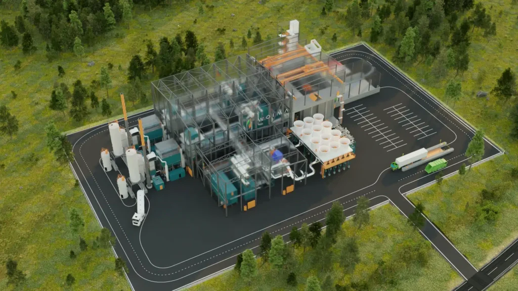
A forestry biomass power plant is a renewable energy facility that harnesses wood and organic residues from forests—including branches, tops, bark, thinning materials, sawdust, chips, and other by-products from logging and timber processing—to produce electricity, heat, and other forms of usable energy, transforming materials that would otherwise be considered waste into a valuable energy resource. Forestry biomass is abundant in regions with extensive forest cover, providing a sustainable and reliable feedstock with relatively high calorific value and predictable energy potential. However, its heterogeneous nature, variable moisture content, and fibrous structure pose significant challenges for collection, transportation, storage, and feeding into energy conversion systems. If not properly managed, forestry residues can degrade, spontaneously combust, or create uneven combustion conditions in boilers and gasifiers. Preprocessing methods such as drying, chipping, grinding, pelletizing, or briquetting are therefore commonly applied to increase energy density, standardize particle size, improve flowability, and enhance combustion or gasification performance. Such preparation ensures continuous and efficient energy conversion, reduces operational problems like slagging, fouling, or uneven burning, and improves overall plant reliability and safety.
Energy conversion in forestry biomass power plants can be achieved through direct combustion, co-firing with other biomass or fossil fuels, or gasification, depending on the scale, type of feedstock, and energy demand. In direct combustion systems, forestry biomass is burned in boilers such as moving grate, fluidized-bed, or suspension-fired units, producing high-temperature flue gases that transfer heat to water or steam circulating in boiler tubes, generating pressurized steam that drives turbines for electricity production. Fluidized-bed boilers are particularly suited for forestry residues because they accommodate heterogeneous, fibrous, and moisture-variable materials, ensuring uniform combustion, reducing unburned residues, minimizing slag formation, and maximizing thermal efficiency. Co-firing forestry biomass with other fuels enhances energy density, stabilizes combustion, and ensures continuous power generation even when feedstock supply fluctuates due to seasonal harvesting or forest management activities. Advanced monitoring and automation systems continuously track parameters such as flame temperature, oxygen concentration, steam pressure, and flue gas composition, allowing precise adjustments that optimize energy output, fuel efficiency, and emissions compliance.
Gasification provides an alternative high-efficiency pathway for forestry biomass utilization, in which the material undergoes partial oxidation at high temperatures to produce syngas—a mixture of carbon monoxide, hydrogen, methane, and carbon dioxide—which can then be combusted in gas engines or turbines for electricity and heat generation, or further processed into biofuels, chemicals, or synthetic fuels. Gasification systems include syngas cleaning and conditioning units to remove tars, particulates, and other impurities, protecting downstream equipment and ensuring reliable operation. Integration with combined heat and power (CHP) systems significantly enhances overall plant efficiency by recovering waste heat from electricity generation to dry incoming forestry biomass, preheat boilers, or supply thermal energy to industrial processes or district heating networks. Effective feedstock management and seasonal storage are critical to maintain a continuous supply of forestry residues, enabling year-round operation even when availability, moisture content, and particle size vary.
Environmental management is a major consideration in forestry biomass power plants because combustion and gasification can produce nitrogen oxides, sulfur oxides, particulate matter, and volatile organic compounds. Modern facilities employ advanced flue gas cleaning technologies such as baghouse filters, electrostatic precipitators, scrubbers, and selective catalytic reduction units to minimize emissions and comply with stringent environmental standards. Combustion residues such as ash are rich in minerals like calcium, potassium, and phosphorus and can be utilized in soil amendments, construction materials, or industrial fillers, promoting circular economy practices and reducing waste disposal challenges. CHP integration ensures nearly complete utilization of the energy content of forestry biomass, lowering fossil fuel consumption, reducing greenhouse gas emissions, and improving overall plant efficiency. Automated feedstock handling, combustion monitoring, and residue management systems enhance operational reliability, reduce labor requirements, and maintain stable energy production even with variations in feedstock characteristics.
Operational management of forestry biomass power plants relies on advanced automation and real-time monitoring to handle fluctuations in feedstock type, particle size, moisture content, and seasonal availability. Dynamic adjustments to fuel feeding rates, combustion air, boiler temperature, and steam pressure are essential to maintain stable electricity and heat output, prevent equipment damage, and ensure safe operations. Safety systems protect personnel and equipment from hazards associated with high-temperature combustion, pressurized steam, and handling abrasive or ash-rich residues. By integrating feedstock preprocessing, optimized energy conversion technologies, CHP systems, emissions control, and residue valorization, forestry biomass power plants provide a continuous, reliable, and environmentally responsible source of electricity, heat, and bio-products, converting forestry residues into high-value energy while supporting carbon mitigation, sustainable forest management, and rural economic development.
The economic and environmental benefits of forestry biomass power plants are substantial. They provide a renewable, abundant, and predictable feedstock, reduce reliance on fossil fuels, mitigate greenhouse gas emissions, and offer practical solutions for forestry residue management. Utilizing forestry residues for energy production generates additional income for forest management and sawmill operations, reduces open-field burning or uncontrolled decomposition that would release methane, and encourages sustainable land use practices. Modular and scalable plant designs allow deployment at community-scale facilities near forested areas or sawmills or at industrial-scale plants supplying electricity and thermal energy to regional grids. By combining efficient feedstock management, advanced energy conversion technologies, CHP integration, emissions control, and ash utilization, forestry biomass power plants operate efficiently, sustainably, and economically, producing renewable energy and valuable by-products while promoting circular economy principles, sustainable forestry, and long-term environmental stewardship.
A forestry biomass power plant is an advanced renewable energy facility designed to utilize wood and organic residues from forest management activities, including tree tops, branches, bark, sawdust, wood chips, and other by-products of logging, thinning, and sawmill operations, to produce electricity, heat, and other forms of usable energy, transforming forestry waste into a valuable and sustainable resource. These facilities play a critical role in regions with extensive forest coverage, where large volumes of residues accumulate and pose disposal challenges, offering a renewable and reliable feedstock with relatively high calorific value and stable energy potential. Effective collection, transportation, and storage are essential because forestry biomass is often heterogeneous, fibrous, and moisture-variable, and improper handling can lead to microbial degradation, spontaneous combustion, or inconsistent feeding, which can impact the efficiency and safety of the plant. Preprocessing methods such as drying, chipping, grinding, pelletizing, and briquetting are commonly used to increase energy density, standardize particle size, and enhance flowability, ensuring consistent combustion or gasification performance, reducing operational issues like slagging or fouling, and optimizing energy output.
Energy conversion in forestry biomass power plants can be achieved through direct combustion, co-firing with other fuels, or gasification, depending on plant design, feedstock type, and energy demands. In direct combustion systems, forestry biomass is burned in boilers such as moving grate, fluidized-bed, or suspension-fired units, producing high-temperature flue gases that transfer heat to water or steam circulating in boiler tubes, generating pressurized steam for turbine-driven electricity production. Fluidized-bed boilers are particularly suitable for forestry residues due to their ability to accommodate heterogeneous and fibrous feedstock with varying moisture content, providing uniform combustion, reducing unburned residues, minimizing slag formation, and maximizing thermal efficiency. Co-firing forestry biomass with other fuels improves energy density, stabilizes combustion, and allows continuous operation even when residue supply fluctuates due to seasonal logging activities or sawmill operations. Advanced automation and monitoring systems track key parameters such as flame temperature, oxygen levels, steam pressure, and flue gas composition in real time, enabling precise adjustments that optimize energy efficiency, output, and emissions compliance.
Gasification offers an alternative high-efficiency conversion pathway for forestry biomass, where feedstock undergoes partial oxidation at high temperatures to produce syngas—a mixture of carbon monoxide, hydrogen, methane, and carbon dioxide—which can be combusted in gas engines or turbines for electricity and heat generation or further processed into biofuels, synthetic fuels, and chemical intermediates. Gasification systems are equipped with syngas cleaning and conditioning units to remove tars, particulates, and other impurities, protecting downstream equipment and ensuring reliable operation. Integration with combined heat and power (CHP) systems significantly enhances overall efficiency by recovering waste heat from electricity generation to dry incoming forestry biomass, preheat boilers, or supply thermal energy to industrial processes or district heating networks. Effective feedstock management and seasonal storage are essential for maintaining a continuous supply of forestry residues, allowing year-round operation despite fluctuations in availability, particle size, and moisture content.
Environmental management is a critical aspect of forestry biomass power plants because combustion and gasification processes can emit nitrogen oxides, sulfur oxides, particulate matter, and volatile organic compounds. Modern plants employ advanced flue gas cleaning technologies, including baghouse filters, electrostatic precipitators, scrubbers, and selective catalytic reduction systems, to minimize emissions and comply with stringent environmental standards. Combustion residues such as ash are rich in minerals like calcium, potassium, and phosphorus and can be repurposed for soil amendments, construction materials, or industrial fillers, supporting circular economy practices and reducing waste disposal challenges. CHP integration maximizes energy recovery, reduces reliance on fossil fuels, lowers greenhouse gas emissions, and enhances overall plant efficiency. Automated feedstock handling, combustion monitoring, and residue management systems improve operational reliability, reduce labor requirements, and ensure consistent energy production even when feedstock properties vary.
Operational management of forestry biomass power plants relies on advanced automation and real-time monitoring to accommodate fluctuations in feedstock type, particle size, moisture content, and seasonal availability. Dynamic adjustments of fuel feed rates, combustion air, boiler temperature, and steam pressure are crucial to maintaining stable electricity and heat output, preventing equipment damage, and ensuring safe operations. Safety systems protect personnel and equipment from hazards associated with high-temperature combustion, pressurized steam, and handling abrasive or ash-rich residues. By integrating feedstock preprocessing, optimized energy conversion technologies, CHP systems, emissions control, and residue valorization, forestry biomass power plants provide a continuous, reliable, and environmentally responsible source of electricity, heat, and bio-products, converting forestry residues into high-value energy while supporting carbon mitigation, sustainable forest management, and rural economic development.
The economic and environmental benefits of forestry biomass power plants are significant. They provide a renewable, abundant, and predictable feedstock, reduce dependence on fossil fuels, mitigate greenhouse gas emissions, and offer practical solutions for forestry residue management. Utilizing forestry residues for energy generation creates additional revenue for logging, forest management, and sawmill operations, reduces open-field burning or uncontrolled decomposition that would release methane, and encourages sustainable forest practices. Modular and scalable plant designs allow deployment at community-scale facilities near forested areas or sawmills, or at industrial-scale plants supplying electricity and thermal energy to regional grids. By combining efficient feedstock management, advanced energy conversion technologies, CHP integration, emissions control, and ash utilization, forestry biomass power plants operate efficiently, sustainably, and economically, producing renewable energy and valuable by-products while promoting circular economy principles, sustainable forestry, and long-term environmental stewardship.
A forestry biomass power plant is a renewable energy facility designed to efficiently utilize wood and organic residues generated from forests, including branches, tree tops, bark, sawdust, wood chips, thinnings, and other by-products from logging and timber processing, converting them into electricity, heat, and other valuable energy forms. These plants play a crucial role in forested regions where large amounts of residues accumulate and could otherwise create waste management challenges or environmental hazards. Forestry biomass provides a reliable, renewable feedstock with relatively high calorific value and consistent energy potential, making it ideal for year-round energy generation. However, its heterogeneous nature, variable moisture content, and fibrous composition create challenges for collection, storage, and feeding into energy conversion systems, as improper handling can lead to microbial degradation, spontaneous combustion, or uneven combustion that reduces efficiency and reliability. Preprocessing techniques such as drying, chipping, grinding, pelletizing, and briquetting are commonly employed to increase energy density, standardize particle size, improve flowability, and optimize combustion or gasification performance, ensuring smooth, continuous, and efficient energy production while minimizing operational issues like slagging, fouling, or uneven heat release.
Energy conversion in forestry biomass power plants is typically achieved through direct combustion, co-firing with other fuels, or gasification, depending on plant design, feedstock characteristics, and energy requirements. In direct combustion systems, forestry biomass is burned in boilers such as moving grate, fluidized-bed, or suspension-fired units, producing high-temperature flue gases that transfer heat to water or steam circulating in boiler tubes, generating pressurized steam to drive turbines for electricity production. Fluidized-bed boilers are particularly well-suited for forestry residues because they can accommodate heterogeneous and fibrous feedstock with variable moisture content, providing uniform combustion, reducing unburned residues, minimizing slag formation, and maximizing thermal efficiency. Co-firing forestry biomass with other biomass or fossil fuels increases energy density, stabilizes combustion, and ensures continuous energy generation even when residue supply fluctuates due to seasonal harvesting or forest management schedules. Modern automation and monitoring systems track key parameters such as flame temperature, oxygen levels, steam pressure, and flue gas composition in real time, enabling precise adjustments that optimize energy efficiency, output, and emissions compliance.
Gasification represents a high-efficiency alternative pathway for forestry biomass utilization, where feedstock undergoes partial oxidation at elevated temperatures to produce syngas, a mixture of carbon monoxide, hydrogen, methane, and carbon dioxide. This syngas can be combusted in gas engines or turbines to generate electricity and heat, or further processed into biofuels, synthetic fuels, and chemical intermediates. Gasification systems include syngas cleaning and conditioning equipment to remove tars, particulates, and other impurities, protecting downstream machinery and ensuring reliable operation. Integration with combined heat and power (CHP) systems significantly enhances overall efficiency by capturing waste heat from electricity generation to dry incoming biomass, preheat boilers, or supply thermal energy to industrial processes or district heating networks. Effective feedstock management and seasonal storage are crucial to maintain a reliable supply of forestry residues, allowing continuous plant operation even when availability, moisture content, or particle size vary.
Environmental management is a major focus in forestry biomass power plants, as combustion and gasification can generate nitrogen oxides, sulfur oxides, particulate matter, and volatile organic compounds. Advanced flue gas cleaning technologies, including baghouse filters, electrostatic precipitators, scrubbers, and selective catalytic reduction systems, are used to minimize emissions and meet stringent environmental regulations. Combustion residues such as ash are rich in minerals like calcium, potassium, and phosphorus and can be reused as soil amendments, construction materials, or industrial fillers, promoting circular economy practices and reducing waste disposal challenges. CHP integration maximizes energy utilization, reduces fossil fuel dependency, lowers greenhouse gas emissions, and improves overall plant efficiency. Automated feedstock handling, combustion monitoring, and residue management systems improve operational reliability, reduce labor requirements, and maintain consistent energy production despite fluctuations in feedstock properties.
Operational management of forestry biomass power plants relies on advanced automation and real-time monitoring to handle variations in feedstock type, particle size, moisture content, and seasonal availability. Dynamic adjustments to fuel feed rates, combustion air, boiler temperature, and steam pressure are essential to maintain stable electricity and heat output, prevent equipment damage, and ensure safe operations. Safety systems are implemented to protect personnel and equipment from hazards associated with high-temperature combustion, pressurized steam, and handling of abrasive or ash-rich residues. By integrating feedstock preprocessing, optimized energy conversion technologies, CHP systems, emissions control, and residue valorization, forestry biomass power plants provide a continuous, reliable, and environmentally responsible source of electricity, heat, and bio-products, transforming forestry residues into high-value energy while supporting carbon mitigation, sustainable forest management, and rural economic development.
The economic and environmental benefits of forestry biomass power plants are considerable. They provide a renewable, abundant, and predictable feedstock, reduce dependence on fossil fuels, mitigate greenhouse gas emissions, and offer practical solutions for managing forestry residues. Using forestry residues for energy generation creates additional revenue streams for forest management and sawmill operations, reduces open-field burning or uncontrolled decomposition that would release methane, and encourages sustainable forest practices. Modular and scalable plant designs allow deployment at small-scale community facilities near logging operations or sawmills, as well as at industrial-scale plants supplying electricity and thermal energy to regional grids. By combining efficient feedstock management, advanced energy conversion technologies, CHP integration, emissions control, and ash utilization, forestry biomass power plants operate efficiently, sustainably, and economically, producing renewable energy and valuable by-products while promoting circular economy principles, sustainable forestry, and long-term environmental stewardship.
A forestry biomass power plant is a state-of-the-art renewable energy facility that converts wood and organic residues from forest management and logging activities—including tree tops, branches, bark, sawdust, chips, and other timber by-products—into electricity, heat, and other forms of usable energy, effectively transforming forestry waste into a valuable and sustainable energy resource. These plants are especially important in regions with large forested areas, where residual biomass accumulates and may otherwise pose disposal problems or environmental risks. Forestry biomass is a renewable, abundant, and relatively high-calorific feedstock, providing consistent energy potential suitable for year-round operation. However, its heterogeneous nature, variable moisture content, and fibrous composition present challenges in collection, transportation, storage, and feeding into boilers or gasifiers, as improper handling can result in microbial degradation, spontaneous combustion, or inconsistent fuel delivery, which reduces efficiency and operational reliability. To address these issues, preprocessing methods such as drying, chipping, grinding, pelletizing, and briquetting are commonly applied to standardize particle size, increase energy density, improve flowability, and optimize combustion or gasification performance, ensuring continuous, efficient, and safe energy production while minimizing operational problems like slag formation, fouling, or uneven heat release.
Energy conversion in forestry biomass power plants can be achieved through direct combustion, co-firing with other biomass or fossil fuels, or gasification, depending on plant scale, feedstock characteristics, and energy demands. In direct combustion systems, forestry residues are burned in boilers such as moving grate, fluidized-bed, or suspension-fired units, producing high-temperature flue gases that heat water or steam circulating in boiler tubes, generating pressurized steam that drives turbines for electricity production. Fluidized-bed boilers are particularly well-suited for forestry biomass because they accommodate heterogeneous, fibrous, and moisture-variable feedstock, ensuring uniform combustion, minimizing unburned residues, reducing slag formation, and maximizing thermal efficiency. Co-firing forestry biomass with other fuels improves energy density, stabilizes combustion, and allows continuous operation even when residue availability fluctuates due to seasonal logging or sawmill activities. Modern plants employ advanced automation and monitoring systems that continuously track flame temperature, oxygen concentration, steam pressure, and flue gas composition, allowing real-time adjustments to optimize energy output, fuel efficiency, and emissions compliance.
Gasification provides a highly efficient alternative pathway for energy production in forestry biomass plants, where feedstock undergoes partial oxidation at elevated temperatures to produce syngas—a mixture of carbon monoxide, hydrogen, methane, and carbon dioxide—which can be combusted in gas engines or turbines for electricity and heat generation, or further processed into biofuels, synthetic fuels, and chemical intermediates. Gasification systems are equipped with syngas cleaning and conditioning units to remove tars, particulates, and other contaminants, protecting downstream equipment and ensuring reliable operation. Integration with combined heat and power (CHP) systems significantly enhances overall plant efficiency by recovering waste heat from electricity generation to dry incoming forestry biomass, preheat boilers, or supply thermal energy to industrial processes or district heating networks. Effective feedstock management and seasonal storage are critical to maintaining a continuous supply of forestry residues, enabling uninterrupted operation even when feedstock availability, moisture content, or particle size vary.
Environmental management is a core consideration in forestry biomass power plants because combustion and gasification processes can emit nitrogen oxides, sulfur oxides, particulate matter, and volatile organic compounds. Advanced flue gas cleaning technologies, including baghouse filters, electrostatic precipitators, scrubbers, and selective catalytic reduction systems, are employed to minimize emissions and comply with stringent environmental regulations. Combustion residues, particularly ash, are rich in minerals such as calcium, potassium, and phosphorus, and can be repurposed as soil amendments, construction materials, or industrial fillers, promoting circular economy practices and reducing waste disposal challenges. CHP integration ensures nearly complete utilization of the energy content of forestry biomass, reducing reliance on fossil fuels, lowering greenhouse gas emissions, and improving overall plant efficiency. Automated feedstock handling, combustion monitoring, and residue management systems enhance operational reliability, reduce labor requirements, and maintain consistent energy production even with variations in feedstock properties.
Operational management of forestry biomass power plants depends on advanced automation and real-time monitoring to manage fluctuations in feedstock type, particle size, moisture content, and seasonal availability. Dynamic adjustments to fuel feeding rates, combustion air, boiler temperature, and steam pressure are essential to maintain stable electricity and heat output, prevent equipment damage, and ensure safe operations. Safety systems protect personnel and equipment from hazards associated with high-temperature combustion, pressurized steam, and handling abrasive or ash-rich residues. By integrating feedstock preprocessing, optimized energy conversion technologies, CHP systems, emissions control, and residue valorization, forestry biomass power plants provide a continuous, reliable, and environmentally responsible source of electricity, heat, and bio-products, converting forestry residues into high-value energy while supporting carbon mitigation, sustainable forest management, and rural economic development.
The economic and environmental advantages of forestry biomass power plants are substantial. They provide a renewable, abundant, and predictable feedstock, reduce dependence on fossil fuels, mitigate greenhouse gas emissions, and offer practical solutions for managing forestry residues. Utilizing forestry residues for energy generation creates additional revenue for forest management and sawmill operations, reduces open-field burning or uncontrolled decomposition that would release methane, and encourages sustainable forest practices. Modular and scalable plant designs allow deployment at community-scale facilities near logging operations or sawmills, or at industrial-scale plants supplying electricity and thermal energy to regional grids. By combining efficient feedstock management, advanced energy conversion technologies, CHP integration, emissions control, and ash utilization, forestry biomass power plants operate efficiently, sustainably, and economically, producing renewable energy and valuable by-products while promoting circular economy principles, sustainable forestry, and long-term environmental stewardship.
Agricultural Biomass Power Plant
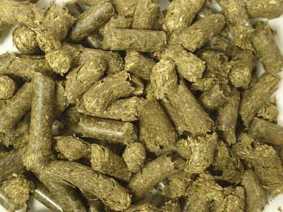
An agricultural biomass power plant is a renewable energy facility designed to convert residues and by-products from agricultural activities into electricity, heat, and other useful forms of energy, providing a sustainable solution for managing crop waste that would otherwise be discarded or left to decompose. These residues include crop stalks, husks, leaves, straw, shells, cobs, and other organic materials generated during harvesting, processing, and post-harvest operations, and they represent a significant and underutilized source of energy in farming regions. Agricultural biomass is generally abundant, widely distributed, and renewable, offering predictable energy potential, but its heterogeneous composition, variable moisture content, and seasonal availability present operational challenges for collection, transportation, storage, and feeding into energy conversion systems. Improper handling can result in microbial degradation, spontaneous combustion, or inconsistent combustion, which can reduce plant efficiency and reliability. Preprocessing techniques such as drying, grinding, pelletizing, briquetting, or compacting are employed to increase energy density, standardize particle size, and improve flowability, ensuring consistent and efficient energy conversion while minimizing issues like slagging, fouling, or uneven burning.
Energy conversion in agricultural biomass power plants can be achieved through direct combustion, co-firing with other biomass or fossil fuels, or gasification, depending on feedstock characteristics, plant size, and energy requirements. In direct combustion systems, agricultural residues are burned in boilers such as moving grate, fluidized-bed, or suspension-fired units, producing high-temperature flue gases that transfer heat to water or steam in boiler tubes, generating pressurized steam to drive turbines for electricity production. Fluidized-bed boilers are particularly suitable for agricultural biomass because they accommodate heterogeneous, fibrous, and moisture-variable feedstock, ensuring uniform combustion, reducing unburned residues, minimizing slag formation, and maximizing thermal efficiency. Co-firing agricultural residues with other biomass or fossil fuels enhances energy density, stabilizes combustion, and allows continuous operation even when feedstock supply fluctuates due to seasonal crop cycles. Modern plants employ advanced monitoring and automation systems to track flame temperature, oxygen concentration, steam pressure, and flue gas composition, enabling real-time adjustments that optimize energy output, fuel efficiency, and emissions compliance.
Gasification offers an alternative high-efficiency pathway for agricultural biomass energy production, in which the feedstock undergoes partial oxidation at high temperatures to produce syngas—a mixture of carbon monoxide, hydrogen, methane, and carbon dioxide—which can be combusted in gas engines or turbines for electricity and heat generation or further processed into biofuels, synthetic fuels, or chemical products. Gasification systems are equipped with syngas cleaning and conditioning units to remove tars, particulates, and other contaminants, protecting downstream equipment and ensuring reliable operation. Integration with combined heat and power (CHP) systems significantly enhances overall plant efficiency by recovering waste heat from electricity generation to dry incoming biomass, preheat boilers, or supply thermal energy to industrial processes, greenhouses, or district heating networks. Effective feedstock management and storage are essential to maintain a continuous supply of agricultural residues, enabling uninterrupted operation even when feedstock availability, moisture content, or particle size varies seasonally.
Environmental management is a critical focus in agricultural biomass power plants, as combustion and gasification processes can generate nitrogen oxides, sulfur oxides, particulate matter, and volatile organic compounds. Advanced flue gas cleaning technologies, including baghouse filters, electrostatic precipitators, scrubbers, and selective catalytic reduction systems, are implemented to minimize emissions and comply with stringent environmental regulations. Combustion residues, particularly ash, are rich in minerals such as potassium, phosphorus, and calcium, which can be reused as fertilizers, soil amendments, or construction materials, promoting circular economy practices and reducing waste disposal challenges. CHP integration maximizes energy utilization, reduces fossil fuel dependency, lowers greenhouse gas emissions, and improves overall plant efficiency. Automated feedstock handling, combustion monitoring, and residue management systems enhance operational reliability, reduce labor requirements, and maintain stable energy production despite fluctuations in feedstock characteristics.
Operational management of agricultural biomass power plants relies on sophisticated automation and real-time monitoring to handle variations in feedstock type, particle size, moisture content, and seasonal availability. Dynamic adjustments of fuel feeding rates, combustion air, boiler temperature, and steam pressure are essential to maintain stable electricity and heat output, prevent equipment damage, and ensure safe operation. Safety systems protect personnel and equipment from hazards associated with high-temperature combustion, pressurized steam, and handling abrasive or ash-rich residues. By integrating feedstock preprocessing, optimized energy conversion technologies, CHP systems, emissions control, and residue valorization, agricultural biomass power plants provide a continuous, reliable, and environmentally responsible source of electricity, heat, and bio-products, converting agricultural residues into high-value energy while supporting carbon mitigation, sustainable farming practices, and rural economic development.
The economic and environmental advantages of agricultural biomass power plants are considerable. They provide a renewable, abundant, and predictable feedstock, reduce reliance on fossil fuels, mitigate greenhouse gas emissions, and offer practical solutions for managing agricultural residues. Utilizing crop residues for energy generation creates additional revenue streams for farmers and agricultural processing facilities, reduces open-field burning or uncontrolled decomposition that would release methane, and encourages sustainable land use and farming practices. Modular and scalable plant designs allow deployment at small-scale facilities near farms or processing centers or at industrial-scale plants supplying electricity and thermal energy to regional grids. By combining efficient feedstock management, advanced energy conversion technologies, CHP integration, emissions control, and ash utilization, agricultural biomass power plants operate efficiently, sustainably, and economically, producing renewable energy and valuable by-products while promoting circular economy principles, sustainable agriculture, and long-term environmental stewardship.
An agricultural biomass power plant is a modern renewable energy facility that converts organic residues and by-products from agricultural activities, including crop stalks, husks, straw, leaves, shells, cobs, and other materials generated during harvesting, processing, and post-harvest operations, into electricity, heat, and other useful energy forms, turning what would otherwise be waste into a valuable, sustainable resource. Agricultural biomass is abundant in farming regions and represents a reliable source of renewable energy, though it is highly heterogeneous, seasonally variable, and often contains significant moisture, which can complicate collection, transportation, storage, and feeding into boilers or gasification systems. Improper handling can result in microbial degradation, spontaneous combustion, or inconsistent combustion performance, reducing plant efficiency and reliability. To address these challenges, preprocessing methods such as drying, grinding, pelletizing, briquetting, or compacting are employed to increase energy density, standardize particle size, and improve flowability, ensuring consistent and efficient energy conversion while minimizing operational issues like slagging, fouling, or uneven burning. These processes are critical for maintaining stable energy output and extending the lifespan of plant equipment.
Energy conversion in agricultural biomass power plants can be achieved through direct combustion, co-firing with other biomass or fossil fuels, or gasification, depending on feedstock characteristics, plant capacity, and energy requirements. In direct combustion systems, agricultural residues are burned in boilers such as moving grate, fluidized-bed, or suspension-fired units, producing high-temperature flue gases that transfer heat to water or steam circulating in boiler tubes, generating pressurized steam to drive turbines for electricity production. Fluidized-bed boilers are particularly well-suited for agricultural residues because they can handle heterogeneous and fibrous feedstock with variable moisture content, ensuring uniform combustion, reducing unburned residues, minimizing slag formation, and maximizing thermal efficiency. Co-firing agricultural biomass with other fuels improves energy density, stabilizes combustion, and allows continuous operation even when residue availability fluctuates due to seasonal crop cycles. Advanced automation and real-time monitoring systems track key operational parameters such as flame temperature, oxygen levels, steam pressure, and flue gas composition, enabling precise adjustments that optimize energy output, fuel efficiency, and emissions compliance.
Gasification offers an alternative high-efficiency pathway for agricultural biomass utilization, in which the feedstock undergoes partial oxidation at high temperatures to produce syngas—a mixture of carbon monoxide, hydrogen, methane, and carbon dioxide—which can be combusted in gas engines or turbines for electricity and heat generation or processed into biofuels, synthetic fuels, and chemical intermediates. Gasification systems incorporate syngas cleaning and conditioning equipment to remove tars, particulates, and other impurities, protecting downstream equipment and ensuring reliable operation. Integration with combined heat and power (CHP) systems further enhances overall plant efficiency by recovering waste heat from electricity generation to dry incoming biomass, preheat boilers, or supply thermal energy to industrial processes, greenhouses, or district heating networks. Efficient feedstock management and seasonal storage are essential to maintain a steady supply of agricultural residues, allowing continuous operation even when feedstock availability, moisture content, or particle size vary throughout the year.
Environmental management is a critical component of agricultural biomass power plants because combustion and gasification processes can emit nitrogen oxides, sulfur oxides, particulate matter, and volatile organic compounds. Advanced flue gas cleaning technologies, including baghouse filters, electrostatic precipitators, scrubbers, and selective catalytic reduction systems, are implemented to minimize emissions and meet strict environmental standards. Combustion residues, particularly ash, are rich in minerals such as potassium, phosphorus, and calcium and can be reused as fertilizers, soil amendments, or construction materials, promoting circular economy practices and reducing waste disposal challenges. CHP integration ensures near-complete utilization of the energy content of agricultural biomass, reduces fossil fuel dependency, lowers greenhouse gas emissions, and improves overall plant efficiency. Automated feedstock handling, combustion monitoring, and residue management systems enhance operational reliability, reduce labor requirements, and maintain stable energy production even when feedstock properties fluctuate.
Operational management of agricultural biomass power plants relies on sophisticated automation and real-time monitoring to handle fluctuations in feedstock type, particle size, moisture content, and seasonal availability. Dynamic adjustments of fuel feeding rates, combustion air, boiler temperature, and steam pressure are essential to maintain stable electricity and heat output, prevent equipment damage, and ensure safe operations. Safety systems protect personnel and equipment from hazards associated with high-temperature combustion, pressurized steam, and handling abrasive or ash-rich residues. By integrating feedstock preprocessing, optimized energy conversion technologies, CHP systems, emissions control, and residue valorization, agricultural biomass power plants provide a continuous, reliable, and environmentally responsible source of electricity, heat, and bio-products, transforming agricultural residues into high-value energy while supporting carbon mitigation, sustainable farming practices, and rural economic development.
The economic and environmental benefits of agricultural biomass power plants are substantial. They provide a renewable, abundant, and predictable feedstock, reduce dependence on fossil fuels, mitigate greenhouse gas emissions, and offer practical solutions for managing agricultural residues. Using crop residues for energy generation creates additional income for farmers and processing facilities, reduces open-field burning or uncontrolled decomposition that would release methane, and promotes sustainable land use and agricultural practices. Modular and scalable plant designs allow deployment at community-scale facilities near farms or processing centers or at industrial-scale plants supplying electricity and thermal energy to regional grids. By combining efficient feedstock management, advanced energy conversion technologies, CHP integration, emissions control, and ash utilization, agricultural biomass power plants operate efficiently, sustainably, and economically, producing renewable energy and valuable by-products while promoting circular economy principles, sustainable agriculture, and long-term environmental stewardship.
An agricultural biomass power plant is a cutting-edge renewable energy facility that converts a wide range of organic residues from agricultural activities, including crop stalks, leaves, straw, husks, cobs, shells, and other post-harvest by-products, into electricity, heat, and other usable energy forms, turning materials that would otherwise be considered waste into a reliable and sustainable energy resource. These plants are particularly valuable in farming regions where large volumes of biomass accumulate and may otherwise be discarded, left to decompose, or burned in open fields, which can contribute to environmental pollution and greenhouse gas emissions. Agricultural biomass is a renewable and widely available feedstock with relatively high calorific content, but it is often heterogeneous, seasonally variable, and contains significant moisture, presenting challenges in collection, transportation, storage, and feeding into energy conversion systems. Without proper handling, microbial degradation or spontaneous combustion can occur, reducing efficiency and operational reliability. Preprocessing techniques such as drying, grinding, pelletizing, briquetting, and compacting are therefore applied to standardize particle size, increase energy density, and improve flowability, ensuring consistent and efficient combustion or gasification performance while minimizing operational issues like slagging, fouling, or uneven heat distribution.
Energy conversion in agricultural biomass power plants can be achieved through direct combustion, co-firing with other biomass or fossil fuels, or gasification, depending on feedstock characteristics, plant scale, and energy requirements. In direct combustion systems, agricultural residues are burned in boilers such as moving grate, fluidized-bed, or suspension-fired units, producing high-temperature flue gases that transfer heat to water or steam circulating through boiler tubes, generating pressurized steam to drive turbines for electricity production. Fluidized-bed boilers are particularly suitable for agricultural residues due to their ability to handle heterogeneous, fibrous, and moisture-variable feedstock, ensuring uniform combustion, reducing unburned residues, minimizing slag formation, and maximizing thermal efficiency. Co-firing agricultural biomass with other fuels enhances energy density, stabilizes combustion, and allows continuous operation even when residue availability fluctuates due to seasonal harvesting cycles. Advanced monitoring and automation systems track critical parameters such as flame temperature, oxygen concentration, steam pressure, and flue gas composition, enabling real-time adjustments that optimize energy output, fuel efficiency, and emissions compliance.
Gasification provides an alternative high-efficiency pathway for converting agricultural biomass into energy, where feedstock undergoes partial oxidation at elevated temperatures to produce syngas—a mixture of carbon monoxide, hydrogen, methane, and carbon dioxide—which can be combusted in gas engines or turbines for electricity and heat generation or further processed into biofuels, synthetic fuels, and chemical intermediates. Gasification systems include syngas cleaning and conditioning units to remove tars, particulates, and other contaminants, protecting downstream equipment and ensuring reliable operation. Integration with combined heat and power (CHP) systems significantly enhances overall plant efficiency by recovering waste heat from electricity generation to dry incoming biomass, preheat boilers, or supply thermal energy to industrial processes, greenhouses, or district heating networks. Proper feedstock management and seasonal storage are essential to maintain a steady supply of agricultural residues, allowing continuous plant operation even when availability, moisture content, or particle size varies throughout the year.
Environmental management is a fundamental consideration in agricultural biomass power plants, as combustion and gasification can emit nitrogen oxides, sulfur oxides, particulate matter, and volatile organic compounds. Modern facilities utilize advanced flue gas cleaning technologies such as baghouse filters, electrostatic precipitators, scrubbers, and selective catalytic reduction systems to minimize emissions and comply with strict environmental regulations. Combustion residues, particularly ash, are rich in minerals such as potassium, phosphorus, and calcium and can be repurposed as fertilizers, soil amendments, or construction materials, supporting circular economy practices and reducing waste disposal challenges. CHP integration ensures nearly complete utilization of the energy content of agricultural biomass, reduces fossil fuel dependence, lowers greenhouse gas emissions, and improves overall plant efficiency. Automated feedstock handling, combustion monitoring, and residue management systems further enhance operational reliability, reduce labor requirements, and maintain stable energy production even when feedstock properties fluctuate.
Operational management of agricultural biomass power plants relies on advanced automation and real-time monitoring to manage variations in feedstock type, particle size, moisture content, and seasonal availability. Dynamic adjustments of fuel feeding rates, combustion air, boiler temperature, and steam pressure are essential to maintain stable electricity and heat output, prevent equipment damage, and ensure safe operation. Safety systems protect personnel and equipment from hazards associated with high-temperature combustion, pressurized steam, and handling abrasive or ash-rich residues. By integrating feedstock preprocessing, optimized energy conversion technologies, CHP systems, emissions control, and residue valorization, agricultural biomass power plants provide a continuous, reliable, and environmentally responsible source of electricity, heat, and bio-products, transforming agricultural residues into high-value energy while supporting carbon mitigation, sustainable farming practices, and rural economic development.
The economic and environmental advantages of agricultural biomass power plants are substantial, providing a renewable, abundant, and predictable feedstock, reducing dependence on fossil fuels, mitigating greenhouse gas emissions, and offering practical solutions for agricultural waste management. Utilizing crop residues for energy generation creates additional income streams for farmers and processing facilities, reduces open-field burning or uncontrolled decomposition that would release methane, and encourages sustainable land use and agricultural practices. Modular and scalable plant designs allow deployment at small-scale community facilities near farms or processing centers, as well as at industrial-scale plants supplying electricity and thermal energy to regional grids. By combining efficient feedstock management, advanced energy conversion technologies, CHP integration, emissions control, and ash utilization, agricultural biomass power plants operate efficiently, sustainably, and economically, producing renewable energy and valuable by-products while promoting circular economy principles, sustainable agriculture, and long-term environmental stewardship.
An agricultural biomass power plant is an advanced renewable energy facility that converts organic residues from agricultural activities, including crop stalks, husks, leaves, straw, shells, cobs, and other by-products of harvesting, processing, and post-harvest operations, into electricity, thermal energy, and other usable forms of energy, transforming materials that would otherwise be considered waste into a sustainable and valuable energy resource. These plants are particularly significant in regions with extensive agricultural production, where large volumes of crop residues accumulate and can create disposal challenges or environmental hazards if left unmanaged or burned openly. Agricultural biomass is abundant, renewable, and possesses a relatively high calorific value, making it an attractive feedstock for continuous energy production; however, its heterogeneous nature, seasonal variability, and high moisture content present operational challenges in collection, transport, storage, and feeding into boilers or gasifiers. Improper handling can lead to microbial degradation, spontaneous combustion, or inconsistent combustion conditions that negatively affect efficiency and reliability. To address these challenges, preprocessing techniques such as drying, grinding, pelletizing, briquetting, and compacting are commonly employed to standardize particle size, increase energy density, improve flowability, and optimize combustion or gasification performance, ensuring consistent and efficient energy conversion while minimizing issues such as slagging, fouling, or uneven heat release.
Energy conversion in agricultural biomass power plants can be achieved through direct combustion, co-firing with other biomass or fossil fuels, or gasification, depending on the type of feedstock, plant capacity, and energy demand. In direct combustion systems, agricultural residues are burned in boilers such as moving grate, fluidized-bed, or suspension-fired units, producing high-temperature flue gases that transfer heat to water or steam circulating through boiler tubes, generating pressurized steam to drive turbines for electricity production. Fluidized-bed boilers are particularly suitable for agricultural biomass because they can accommodate heterogeneous, fibrous, and moisture-variable feedstock, ensuring uniform combustion, minimizing unburned residues, reducing slag formation, and maximizing thermal efficiency. Co-firing agricultural biomass with other fuels improves energy density, stabilizes combustion, and allows continuous operation even when feedstock availability fluctuates due to seasonal harvesting cycles or variable crop production. Advanced automation and real-time monitoring systems track critical operational parameters such as flame temperature, oxygen concentration, steam pressure, and flue gas composition, allowing precise adjustments that optimize energy output, fuel efficiency, and emissions compliance.
Gasification offers a highly efficient alternative pathway for converting agricultural biomass into energy, in which feedstock undergoes partial oxidation at high temperatures to produce syngas—a mixture of carbon monoxide, hydrogen, methane, and carbon dioxide—which can be combusted in gas engines or turbines for electricity and heat generation or further processed into biofuels, synthetic fuels, and chemical intermediates. Gasification systems incorporate syngas cleaning and conditioning equipment to remove tars, particulates, and other impurities, protecting downstream equipment and ensuring reliable operation. Integration with combined heat and power (CHP) systems further enhances overall plant efficiency by recovering waste heat from electricity generation to dry incoming biomass, preheat boilers, or supply thermal energy to industrial processes, greenhouses, or district heating networks. Efficient feedstock management and seasonal storage are critical to maintain a continuous supply of agricultural residues, enabling uninterrupted plant operation even when feedstock characteristics, moisture content, or availability fluctuate throughout the year.
Environmental management is a key focus in agricultural biomass power plants because combustion and gasification processes can emit nitrogen oxides, sulfur oxides, particulate matter, and volatile organic compounds. Modern plants employ advanced flue gas cleaning technologies, including baghouse filters, electrostatic precipitators, scrubbers, and selective catalytic reduction systems, to minimize emissions and comply with strict environmental regulations. Combustion residues, particularly ash, are rich in minerals such as potassium, phosphorus, and calcium and can be reused as fertilizers, soil amendments, or construction materials, promoting circular economy practices and reducing waste disposal challenges. CHP integration maximizes energy utilization, reduces fossil fuel dependence, lowers greenhouse gas emissions, and improves overall plant efficiency. Automated feedstock handling, combustion monitoring, and residue management systems enhance operational reliability, reduce labor requirements, and maintain stable energy production even when feedstock properties vary significantly.
Operational management of agricultural biomass power plants relies on sophisticated automation and real-time monitoring to handle variations in feedstock type, particle size, moisture content, and seasonal availability. Dynamic adjustments of fuel feed rates, combustion air, boiler temperature, and steam pressure are essential to maintain stable electricity and heat output, prevent equipment damage, and ensure safe operation. Safety systems protect personnel and equipment from hazards associated with high-temperature combustion, pressurized steam, and handling abrasive or ash-rich residues. By integrating feedstock preprocessing, optimized energy conversion technologies, CHP systems, emissions control, and residue valorization, agricultural biomass power plants provide a continuous, reliable, and environmentally responsible source of electricity, heat, and bio-products, transforming agricultural residues into high-value energy while supporting carbon mitigation, sustainable farming practices, and rural economic development.
The economic and environmental benefits of agricultural biomass power plants are substantial, providing a renewable, abundant, and predictable feedstock, reducing reliance on fossil fuels, mitigating greenhouse gas emissions, and offering practical solutions for agricultural waste management. Utilizing crop residues for energy generation creates additional income streams for farmers and agricultural processing facilities, reduces open-field burning or uncontrolled decomposition that would release methane, and encourages sustainable land use and agricultural practices. Modular and scalable plant designs allow deployment at small community-scale facilities near farms or processing centers or at industrial-scale plants supplying electricity and thermal energy to regional grids. By combining efficient feedstock management, advanced energy conversion technologies, CHP integration, emissions control, and ash utilization, agricultural biomass power plants operate efficiently, sustainably, and economically, producing renewable energy and valuable by-products while promoting circular economy principles, sustainable agriculture, and long-term environmental stewardship.
Biomass Energy Systems
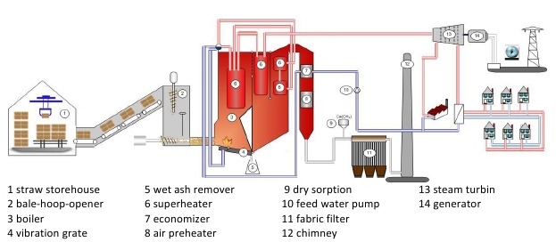
Biomass energy systems are comprehensive renewable energy solutions that convert organic materials, including forestry residues, agricultural by-products, dedicated energy crops, and municipal or industrial organic waste, into electricity, heat, biofuels, or a combination of these energy forms, creating a sustainable alternative to fossil fuels. These systems capitalize on the energy stored in plant biomass, which can be transformed through processes such as direct combustion, gasification, pyrolysis, anaerobic digestion, fermentation, or co-firing with conventional fuels, depending on feedstock characteristics, desired energy output, and technological configuration. Biomass energy systems are particularly valuable because they utilize locally available feedstocks, reduce waste accumulation, and contribute to carbon-neutral energy production, as the carbon dioxide released during energy conversion is offset by the carbon absorbed during the growth of the biomass. However, the heterogeneous nature of biomass, seasonal availability, moisture content, and variable calorific value pose challenges for feedstock handling, storage, and processing, which must be addressed to ensure efficient, reliable, and continuous energy production.
Energy conversion in biomass energy systems often begins with preprocessing of the feedstock, which can include drying, shredding, grinding, pelletizing, or briquetting to increase energy density, standardize particle size, and improve flow characteristics. Direct combustion systems burn the biomass in boilers, producing high-temperature flue gases that heat water or generate steam, which can then drive turbines for electricity generation or provide thermal energy for industrial processes, district heating, or combined heat and power (CHP) applications. Fluidized-bed, moving grate, and suspension-fired boilers are commonly used in modern biomass plants because they accommodate heterogeneous and fibrous feedstock, maintain stable combustion, reduce unburned residues, and optimize thermal efficiency. Co-firing biomass with other fuels, such as coal or natural gas, is often implemented to increase energy density, stabilize combustion, and ensure continuous operation during fluctuations in biomass availability, creating hybrid systems that maximize both flexibility and efficiency.
Gasification is another critical component of advanced biomass energy systems, in which biomass undergoes partial oxidation at high temperatures to produce syngas, a mixture of carbon monoxide, hydrogen, methane, and carbon dioxide. Syngas can be combusted in gas engines or turbines for electricity and heat production or upgraded into biofuels and chemical intermediates. These systems include syngas cleaning and conditioning equipment to remove tars, particulates, and contaminants, protecting downstream machinery and maintaining efficient operation. Integration with CHP systems further enhances overall energy efficiency by capturing waste heat from electricity generation to preheat incoming feedstock, dry biomass, or supply thermal energy for industrial or residential applications, allowing near-total utilization of the energy content of the feedstock.
Environmental management is a fundamental aspect of biomass energy systems, as combustion and gasification processes can produce nitrogen oxides, sulfur oxides, particulate matter, and volatile organic compounds. Modern biomass facilities utilize advanced emission control technologies, including baghouse filters, electrostatic precipitators, scrubbers, and selective catalytic reduction systems, to minimize environmental impact and comply with stringent regulations. Ash and other combustion residues are often rich in minerals such as calcium, potassium, and phosphorus, which can be repurposed as soil amendments, fertilizers, or construction materials, supporting circular economy principles and reducing waste disposal challenges. Efficient feedstock management, storage, and automated handling systems are critical to ensure continuous operation, prevent degradation or combustion hazards, and maintain consistent energy output despite variations in feedstock type, moisture content, or calorific value.
Operational efficiency in biomass energy systems relies heavily on real-time monitoring, automation, and control of feedstock supply, combustion conditions, boiler or gasifier performance, and turbine or engine operation. Dynamic adjustments to fuel feed rates, combustion air, steam temperature, pressure, and other critical parameters ensure stable electricity and heat output, prevent equipment damage, and guarantee safe operation. Safety measures protect personnel and equipment from hazards associated with high-temperature combustion, pressurized steam, and handling of abrasive or ash-rich residues. By integrating advanced feedstock preprocessing, optimized energy conversion technologies, CHP systems, emissions control, and residue valorization, biomass energy systems deliver continuous, reliable, and environmentally responsible energy production, transforming agricultural, forestry, and organic waste into high-value electricity, heat, and bio-products while promoting sustainability, rural economic development, and carbon emission reduction.
Economically and environmentally, biomass energy systems provide significant benefits by supplying a renewable, locally available, and predictable source of energy, reducing dependence on fossil fuels, mitigating greenhouse gas emissions, and offering practical solutions for organic waste management. Using biomass for energy generation creates additional revenue streams for farmers, foresters, municipalities, and industries, prevents uncontrolled decomposition or open-field burning that would release methane, and supports sustainable land use and forest management practices. Modular and scalable designs allow deployment of small-scale community or farm-based facilities as well as industrial-scale power plants supplying electricity and thermal energy to regional grids. By combining efficient feedstock management, advanced conversion technologies, CHP integration, emissions control, and by-product utilization, biomass energy systems operate sustainably, efficiently, and economically, producing renewable energy, valuable bio-products, and long-term environmental, social, and economic benefits.
Biomass energy systems are sophisticated renewable energy solutions that utilize organic materials from forestry, agriculture, municipal solid waste, and industrial by-products to produce electricity, heat, and biofuels, transforming low-value waste into high-value energy and creating a sustainable alternative to fossil fuels. These systems rely on the inherent energy stored in biomass, which can be harnessed through processes such as direct combustion, co-firing, gasification, pyrolysis, anaerobic digestion, and fermentation, depending on the type of feedstock, desired energy output, and technological configuration. Biomass energy systems are particularly valuable because they make use of locally available resources, reduce the environmental impact of organic waste accumulation, and contribute to carbon-neutral energy production, as the carbon dioxide released during energy conversion is offset by the carbon absorbed during the growth of the biomass. However, the heterogeneous nature of biomass, variability in moisture content, calorific value, and seasonal availability present operational challenges that require careful handling, preprocessing, and storage to ensure reliable, continuous, and efficient energy production.
Feedstock preprocessing is a crucial component of biomass energy systems, as it improves energy density, standardizes particle size, and facilitates smooth fuel flow into energy conversion units. Preprocessing techniques include drying, grinding, shredding, pelletizing, and briquetting, each of which enhances combustion or gasification performance while minimizing operational issues such as slagging, fouling, or uneven heat distribution. Direct combustion systems are common in biomass plants, where feedstock is burned in boilers—such as fluidized-bed, moving grate, or suspension-fired units—to generate high-temperature flue gases that transfer heat to water or steam circulating in boiler tubes, producing pressurized steam to drive turbines for electricity generation or provide thermal energy for industrial processes, district heating, or combined heat and power (CHP) applications. Fluidized-bed boilers, in particular, are well-suited for handling heterogeneous and fibrous biomass feedstock with variable moisture content, ensuring uniform combustion, high thermal efficiency, and minimal unburned residues. Co-firing biomass with fossil fuels or other types of biomass can stabilize combustion, increase energy density, and allow continuous operation even when the supply of primary feedstock fluctuates due to seasonal cycles or supply chain constraints.
Gasification offers an advanced alternative for high-efficiency biomass energy conversion, in which feedstock is partially oxidized at high temperatures to produce syngas—a mixture of hydrogen, carbon monoxide, methane, and carbon dioxide—that can be used for electricity generation in gas engines or turbines or further processed into biofuels and chemical intermediates. Gasification systems are equipped with syngas cleaning and conditioning technologies to remove particulates, tars, and other contaminants, ensuring safe and reliable operation of downstream equipment. Integration with CHP systems significantly enhances overall efficiency by recovering waste heat from electricity generation to pre-dry biomass, preheat boilers, or supply thermal energy to industrial facilities, greenhouses, or district heating networks, maximizing the total energy extracted from the feedstock. Seasonal storage and strategic feedstock management are essential to maintain uninterrupted operation, as biomass properties, moisture content, and availability can vary significantly throughout the year.
Environmental management is a core aspect of biomass energy systems, as combustion and gasification processes can generate nitrogen oxides, sulfur oxides, particulate matter, and volatile organic compounds. Modern facilities employ advanced emission control technologies, including baghouse filters, electrostatic precipitators, scrubbers, and selective catalytic reduction systems, to minimize the environmental impact and ensure compliance with strict regulatory standards. Residual ash from combustion is rich in minerals such as potassium, phosphorus, and calcium and can be reused as soil amendments, fertilizers, or in construction, promoting circular economy principles and reducing waste disposal challenges. Automated feedstock handling, combustion monitoring, and residue management systems further enhance operational reliability, reduce labor requirements, and maintain consistent energy production despite fluctuations in feedstock quality and composition.
Operational efficiency in biomass energy systems relies on sophisticated monitoring, automation, and control of critical parameters such as fuel feed rates, combustion air supply, boiler temperature, steam pressure, and turbine or engine performance. Dynamic adjustments allow stable electricity and heat production, prevent equipment damage, and ensure safe operations. Safety measures are also implemented to protect personnel and equipment from hazards associated with high-temperature combustion, pressurized steam, and handling of abrasive or ash-rich residues. By integrating feedstock preprocessing, optimized conversion technologies, CHP systems, emission controls, and residue valorization, biomass energy systems provide a reliable, environmentally responsible, and sustainable source of electricity, heat, and bio-products, transforming forestry residues, agricultural waste, and other organic materials into high-value energy while supporting rural development, carbon mitigation, and renewable energy goals.
Economically and environmentally, biomass energy systems offer substantial benefits. They supply a renewable, abundant, and locally available feedstock, reduce dependence on fossil fuels, mitigate greenhouse gas emissions, and provide practical solutions for managing organic waste. Utilizing biomass for energy creates additional revenue streams for farmers, foresters, municipalities, and industries, reduces open-field burning or decomposition that releases methane, and encourages sustainable land and forest management practices. Modular and scalable designs enable deployment of small-scale community or farm-based facilities as well as industrial-scale plants supplying electricity and thermal energy to regional grids. Through efficient feedstock management, advanced conversion technologies, CHP integration, emission control, and by-product utilization, biomass energy systems operate sustainably and economically, producing renewable energy, valuable bio-products, and long-term environmental, social, and economic benefits while promoting circular economy principles and long-term sustainability.
Biomass energy systems are comprehensive renewable energy solutions that convert a wide array of organic materials, including forestry residues, agricultural by-products, energy crops, and municipal or industrial organic waste, into electricity, heat, and biofuels, providing a sustainable alternative to fossil fuels while reducing waste and supporting circular economy principles. These systems exploit the chemical energy stored in biomass through processes such as direct combustion, co-firing, gasification, pyrolysis, anaerobic digestion, and fermentation, with the choice of technology determined by feedstock type, moisture content, energy requirements, and plant capacity. Biomass feedstocks are often heterogeneous, seasonal, and moisture-variable, which can present significant operational challenges for collection, transport, storage, and feeding into conversion systems. Improper handling or storage can result in microbial degradation, self-heating, or uneven energy output, emphasizing the importance of preprocessing techniques such as drying, grinding, pelletizing, briquetting, or compacting to increase energy density, standardize particle size, and optimize fuel handling, flowability, and combustion efficiency.
In energy conversion, direct combustion remains a primary method in biomass energy systems, where preprocessed feedstock is burned in boilers—such as fluidized-bed, moving grate, or suspension-fired designs—to produce high-temperature flue gases that transfer heat to water or steam circulating through boiler tubes, generating pressurized steam for turbines and electricity generation or for industrial and district heating applications. Fluidized-bed boilers are particularly suited to biomass because they can handle heterogeneous, fibrous, and moisture-variable materials while ensuring uniform combustion, reducing unburned residues, minimizing slag formation, and maximizing thermal efficiency. Co-firing biomass with other fuels, such as coal or natural gas, further stabilizes combustion, increases energy density, and ensures reliable continuous operation despite seasonal fluctuations in biomass availability. Advanced automation and real-time monitoring allow precise control of flame temperature, oxygen concentration, steam pressure, and flue gas composition, enabling optimization of energy output, fuel efficiency, and emissions compliance.
Gasification provides a more advanced and high-efficiency pathway for biomass utilization, converting organic feedstock through partial oxidation at elevated temperatures into syngas—a mixture of hydrogen, carbon monoxide, methane, and carbon dioxide—that can be combusted in gas engines or turbines or further refined into biofuels and chemical feedstocks. These systems incorporate syngas cleaning and conditioning technologies to remove tars, particulates, and other impurities, protecting downstream equipment and ensuring efficient and reliable operation. When integrated with combined heat and power (CHP) systems, waste heat from electricity generation can be captured to pre-dry incoming biomass, preheat boilers, or supply thermal energy for industrial processes, district heating, or greenhouse applications, substantially improving overall energy efficiency. Proper feedstock management, seasonal storage, and logistical planning are critical to maintaining uninterrupted operation, as variations in feedstock type, moisture content, and calorific value can otherwise disrupt energy production.
Environmental performance is a central focus in biomass energy systems due to potential emissions of nitrogen oxides, sulfur oxides, particulate matter, and volatile organic compounds during combustion or gasification. Modern facilities employ a combination of emission control technologies, including baghouse filters, electrostatic precipitators, scrubbers, and selective catalytic reduction systems, to meet stringent environmental regulations and minimize ecological impact. Combustion residues, particularly ash, are often rich in valuable minerals such as potassium, calcium, and phosphorus, which can be reused as fertilizers, soil amendments, or construction materials, reinforcing circular economy principles and reducing waste disposal challenges. By maximizing the use of feedstock energy content through CHP systems, optimizing combustion or gasification performance, and recovering usable by-products, biomass energy systems achieve high overall efficiency while minimizing fossil fuel consumption and greenhouse gas emissions.
Operational management of biomass energy systems requires sophisticated automation and real-time monitoring to accommodate fluctuations in feedstock characteristics, moisture levels, particle size, and seasonal availability. Dynamic adjustments of fuel feeding rates, air supply, boiler or gasifier temperature, steam pressure, and turbine or engine performance are essential to maintain stable electricity and heat production, prevent equipment damage, and ensure safe operation. Safety systems are also integral to protect personnel and equipment from hazards associated with high-temperature combustion, pressurized steam, or handling abrasive and ash-rich residues. Through careful integration of feedstock preprocessing, optimized conversion technologies, CHP systems, emission controls, and residue management, biomass energy systems provide reliable, continuous, and environmentally responsible energy production, transforming organic materials into electricity, thermal energy, and bio-products while supporting sustainable development, carbon mitigation, and rural economic growth.
The economic and environmental benefits of biomass energy systems are significant. They provide a renewable, abundant, and locally available feedstock, reduce dependence on fossil fuels, mitigate greenhouse gas emissions, and offer practical solutions for organic waste management. Converting agricultural, forestry, and municipal residues into energy creates additional revenue streams for farmers, foresters, municipalities, and industries, decreases open-field burning or uncontrolled decomposition that releases methane, and promotes sustainable land and forest management practices. Modular and scalable designs allow deployment of small-scale farm or community-based facilities as well as large industrial plants supplying electricity and thermal energy to regional grids. By integrating efficient feedstock management, advanced energy conversion technologies, CHP systems, emissions control, and by-product utilization, biomass energy systems operate sustainably, efficiently, and economically, generating renewable energy, valuable bio-products, and long-term environmental, social, and economic benefits while advancing circular economy principles and long-term energy security.
Biomass energy systems represent an increasingly important segment of renewable energy technologies, designed to harness the stored chemical energy in organic materials from forestry residues, agricultural by-products, dedicated energy crops, and municipal or industrial organic waste streams, converting these materials into electricity, heat, and biofuels for sustainable energy supply. These systems rely on a variety of conversion processes, including direct combustion, co-firing with other fuels, gasification, pyrolysis, anaerobic digestion, and fermentation, with each method selected based on feedstock type, moisture content, energy demands, and plant scale. Agricultural residues such as straw, husks, stalks, leaves, and shells; forestry residues like sawdust, wood chips, and branches; energy crops cultivated for fuel purposes; and organic waste from municipal or industrial sources all provide feedstock, but the heterogeneous nature, seasonal availability, and variable moisture content of biomass present operational challenges for collection, transportation, storage, and processing. Preprocessing techniques like drying, grinding, shredding, pelletizing, and briquetting are crucial to improve energy density, standardize particle size, enhance flow characteristics, and ensure consistent and efficient energy conversion, while minimizing operational problems such as uneven combustion, slagging, fouling, and unburned residues.
Direct combustion is one of the most widely applied methods in biomass energy systems, wherein preprocessed biomass is burned in boilers to generate high-temperature flue gases that transfer thermal energy to water or steam circulating in boiler tubes, producing pressurized steam for driving turbines to generate electricity or for providing thermal energy to industrial processes, district heating networks, or combined heat and power (CHP) systems. Modern boiler technologies, such as fluidized-bed, moving grate, or suspension-fired units, are designed to handle heterogeneous and fibrous biomass feedstocks while maintaining stable combustion, reducing unburned residues, minimizing slag formation, and maximizing thermal efficiency. Co-firing biomass with fossil fuels or other types of biomass further enhances energy density, stabilizes combustion, and allows continuous operation even when the availability of primary feedstock fluctuates due to seasonal variations or supply chain constraints. Advanced automation and real-time monitoring systems track parameters such as flame temperature, oxygen concentration, steam pressure, and flue gas composition, allowing precise control that optimizes energy output, fuel efficiency, and environmental performance.
Gasification represents a high-efficiency alternative for biomass energy systems, converting organic feedstock through partial oxidation at high temperatures into syngas—a combustible mixture of hydrogen, carbon monoxide, methane, and carbon dioxide—that can be used to generate electricity and heat in gas engines or turbines or further processed into biofuels, chemicals, and synthetic fuels. Gasification systems integrate syngas cleaning and conditioning equipment to remove tars, particulates, and other contaminants, protecting downstream machinery and ensuring reliable operation. When combined with CHP systems, waste heat from electricity production is captured to pre-dry biomass, preheat boilers, or supply thermal energy to industrial processes, district heating, or greenhouse operations, significantly increasing overall system efficiency and maximizing energy utilization. Efficient feedstock management and storage are critical to ensure uninterrupted operation, as variations in biomass type, moisture content, particle size, and calorific value can otherwise affect energy production and plant reliability.
Environmental considerations are central to biomass energy systems, as combustion and gasification processes produce emissions of nitrogen oxides, sulfur oxides, particulate matter, and volatile organic compounds. To address this, modern facilities employ advanced flue gas treatment and emissions control technologies, including baghouse filters, electrostatic precipitators, scrubbers, and selective catalytic reduction systems, ensuring compliance with strict environmental regulations and minimizing ecological impact. Residual ash from combustion processes contains minerals such as potassium, phosphorus, and calcium, which can be repurposed as fertilizers, soil amendments, or construction materials, supporting circular economy principles and reducing waste disposal challenges. Integration of CHP systems ensures maximum utilization of feedstock energy content, reduces fossil fuel dependence, lowers greenhouse gas emissions, and improves the overall economic and environmental performance of the system. Automated feedstock handling, combustion or gasification monitoring, and residue management systems further improve operational reliability, reduce labor requirements, and maintain stable energy output despite variations in biomass properties.
Operational management in biomass energy systems requires sophisticated automation, monitoring, and control to handle variability in feedstock quality, moisture content, and seasonal availability. Real-time adjustments of fuel feed rates, combustion air supply, boiler or gasifier temperature, steam pressure, and turbine or engine operation are essential to maintain continuous electricity and heat production, prevent equipment damage, and ensure safe plant operation. Safety systems protect personnel and equipment from hazards related to high-temperature combustion, pressurized steam, and handling of abrasive or ash-rich residues. By integrating advanced feedstock preprocessing, optimized energy conversion technologies, CHP systems, emissions control, and residue valorization, biomass energy systems deliver reliable, continuous, and environmentally responsible energy production, transforming forestry residues, agricultural by-products, and organic waste into high-value electricity, thermal energy, and bio-products while promoting carbon mitigation, rural development, and sustainable energy supply.
The economic and environmental advantages of biomass energy systems are substantial, providing a renewable, locally available, and predictable energy source, reducing dependence on fossil fuels, mitigating greenhouse gas emissions, and offering practical solutions for organic waste management. Converting agricultural, forestry, and municipal residues into energy creates additional revenue streams for farmers, foresters, municipalities, and industries, reduces open-field burning or uncontrolled decomposition that would release methane, and promotes sustainable land and forest management practices. Modular and scalable designs allow deployment of small-scale community or farm-based facilities as well as large industrial plants supplying electricity and heat to regional grids. Through efficient feedstock management, advanced conversion technologies, CHP integration, emissions control, and by-product utilization, biomass energy systems operate efficiently, sustainably, and economically, producing renewable energy, valuable bio-products, and long-term environmental, social, and economic benefits while advancing circular economy principles and long-term energy security.
Biomass Cogeneration Plant
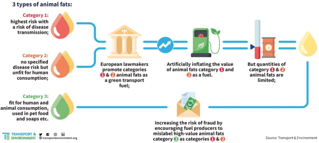
A biomass cogeneration plant is an advanced renewable energy facility designed to produce both electricity and thermal energy simultaneously from organic feedstocks, creating a highly efficient system that maximizes the utilization of biomass resources while minimizing waste and environmental impact. Such plants rely on biomass materials including forestry residues, agricultural by-products, energy crops, municipal organic waste, and industrial organic residues, converting these materials into high-value energy through processes like direct combustion, gasification, pyrolysis, or anaerobic digestion, depending on the type of feedstock, its moisture content, calorific value, and the scale and purpose of the plant. Unlike conventional power plants that produce electricity alone, cogeneration plants capture and utilize waste heat generated during the energy conversion process to supply heat for industrial processes, district heating networks, or drying biomass for further processing, significantly enhancing overall energy efficiency, reducing fuel consumption, and lowering greenhouse gas emissions. Biomass cogeneration is particularly suitable for regions with abundant organic residues, where agricultural, forestry, or municipal biomass would otherwise remain underutilized or disposed of in environmentally damaging ways.
The operational concept of a biomass cogeneration plant integrates fuel handling, energy conversion, and heat recovery systems into a unified process designed to extract maximum energy from biomass. Feedstock is first collected, transported, and preprocessed, often through drying, shredding, grinding, pelletizing, or briquetting, to standardize particle size, reduce moisture content, and enhance fuel flowability. Preprocessed biomass is then fed into a combustion chamber or gasifier, where controlled oxidation produces high-temperature flue gases or syngas. In combustion-based cogeneration systems, these flue gases transfer heat to water or steam circulating in boilers, generating pressurized steam that drives a turbine or steam engine for electricity generation. The residual thermal energy, which would otherwise be wasted in conventional power generation, is captured and used for industrial processes, heating, or preheating and drying incoming biomass, significantly increasing the total efficiency of the plant. In gasification-based cogeneration systems, biomass is converted into syngas, which is cleaned and combusted in gas engines or turbines; the waste heat from this process is similarly recovered and used for heating applications, further enhancing energy efficiency and minimizing fuel consumption.
Biomass cogeneration plants are particularly valuable for their flexibility in fuel sourcing and operational scalability. They can accommodate heterogeneous feedstocks, including fibrous agricultural residues, wood chips, energy crops, and even municipal organic waste, allowing operators to adjust fuel input according to seasonal availability, calorific value, and moisture content. Fluidized-bed, moving-grate, and suspension-fired boilers are commonly employed to maintain stable combustion, reduce unburned residues, and optimize heat transfer efficiency. Co-firing with fossil fuels or alternative biomass can further stabilize energy production and maintain continuous operation despite variations in feedstock supply or quality. Sophisticated automation and real-time monitoring systems ensure precise control over critical parameters such as fuel feed rate, combustion temperature, oxygen concentration, steam pressure, and turbine load, enabling maximum energy output while maintaining safe and efficient operation.
Environmental management is a critical aspect of biomass cogeneration plants, as combustion or gasification processes can generate emissions including nitrogen oxides, sulfur oxides, particulate matter, and volatile organic compounds. Advanced flue gas cleaning technologies, such as baghouse filters, electrostatic precipitators, scrubbers, and selective catalytic reduction systems, are implemented to minimize environmental impact and comply with stringent regulatory standards. Residual ash from combustion is typically rich in minerals like potassium, calcium, and phosphorus and can be reused as fertilizers, soil amendments, or construction materials, supporting circular economy practices and reducing waste disposal requirements. CHP integration ensures near-complete utilization of biomass energy content, reduces reliance on fossil fuels, lowers carbon emissions, and improves overall plant efficiency. Automated feedstock handling and combustion monitoring enhance operational reliability, reduce labor requirements, and maintain consistent energy production even when feedstock properties fluctuate.
Operational efficiency in biomass cogeneration plants relies on precise control and continuous adjustment of feedstock input, combustion or gasification conditions, steam or hot water generation, and electricity and heat output. Safety measures protect personnel and equipment from hazards related to high temperatures, pressurized steam, and handling of ash-rich or abrasive residues. The combination of feedstock preprocessing, optimized energy conversion, CHP integration, emissions control, and residue utilization allows biomass cogeneration plants to provide continuous, reliable, and environmentally responsible energy for electricity, industrial processes, heating, and drying applications. Economically, these plants offer significant benefits by creating additional revenue streams from agricultural, forestry, and municipal residues, reducing waste management costs, and supporting sustainable land and resource management practices. Modular and scalable designs allow deployment at farm, community, or industrial scales, making biomass cogeneration an efficient, flexible, and sustainable solution for renewable energy production while contributing to greenhouse gas mitigation, circular economy practices, and long-term energy security.
A biomass cogeneration plant is a sophisticated energy facility that simultaneously produces electricity and thermal energy from organic feedstocks, maximizing the energy extracted from biomass resources while minimizing waste and environmental impact. These plants utilize a wide variety of feedstocks, including forestry residues, agricultural by-products, energy crops, municipal organic waste, and industrial organic residues, converting these materials into high-value energy through processes such as direct combustion, gasification, pyrolysis, and anaerobic digestion, depending on the feedstock characteristics, moisture content, calorific value, and intended scale and application of the plant. By capturing waste heat that would otherwise be lost in conventional power generation, biomass cogeneration plants supply heat for industrial processes, district heating networks, or drying biomass for further processing, significantly enhancing overall efficiency, reducing fuel consumption, and decreasing greenhouse gas emissions. In rural and agricultural regions where large volumes of crop residues and forestry by-products are produced, cogeneration provides a practical and economically attractive method of converting these materials into electricity and useful thermal energy while reducing the environmental burden of waste disposal or open-field burning.
Operationally, biomass cogeneration plants integrate multiple systems for feedstock collection, preprocessing, energy conversion, and heat recovery to ensure continuous, reliable, and efficient energy production. Feedstock is typically dried, shredded, ground, pelletized, or briquetted to increase energy density, standardize particle size, and improve flow characteristics, allowing for consistent combustion or gasification performance. In direct combustion cogeneration systems, biomass is burned in boilers such as fluidized-bed, moving-grate, or suspension-fired units, producing high-temperature flue gases that transfer heat to water or steam circulating in boiler tubes, generating pressurized steam to drive turbines or engines for electricity production. The residual thermal energy is then recovered and used to meet industrial process heat demands, provide district heating, or preheat and dry incoming biomass, dramatically improving the total energy efficiency of the plant. Gasification-based cogeneration systems operate by partially oxidizing biomass into syngas, which is cleaned and combusted in gas engines or turbines, with waste heat recovered and repurposed similarly for heating or industrial applications, creating a highly flexible and efficient energy platform.
Biomass cogeneration plants are highly adaptable to variable fuel sources, capable of processing heterogeneous feedstocks including fibrous agricultural residues, wood chips, energy crops, and municipal organic waste. Co-firing with other biomass types or fossil fuels can further stabilize combustion, increase energy density, and maintain continuous operation during periods of feedstock variability or seasonal shortages. Advanced automation and real-time monitoring systems ensure precise control over fuel feed rates, combustion temperature, oxygen levels, steam pressure, and electricity and heat outputs, optimizing energy production, fuel efficiency, and emissions performance while maintaining safe operation. The integration of these systems allows cogeneration plants to respond dynamically to changes in feedstock properties, operational demand, and environmental conditions, ensuring consistent and reliable energy delivery.
Environmental considerations are integral to biomass cogeneration plants, as combustion or gasification processes produce nitrogen oxides, sulfur oxides, particulate matter, and volatile organic compounds that must be carefully managed. Modern facilities implement advanced flue gas treatment technologies such as baghouse filters, electrostatic precipitators, scrubbers, and selective catalytic reduction systems to minimize emissions and ensure regulatory compliance. Combustion residues, including ash, are often rich in minerals such as potassium, calcium, and phosphorus, and can be recycled as fertilizers, soil amendments, or construction materials, supporting circular economy principles and reducing waste disposal challenges. The CHP approach ensures maximum utilization of biomass energy content, minimizes fossil fuel use, lowers carbon emissions, and enhances the overall environmental and economic sustainability of the system. Automated feedstock handling, combustion monitoring, and residue management further enhance operational reliability, reduce labor requirements, and maintain stable energy output even when feedstock properties fluctuate.
Economically, biomass cogeneration plants offer significant advantages by converting agricultural, forestry, and municipal residues into energy, creating additional revenue streams for farmers, foresters, municipalities, and industries, reducing waste management costs, and promoting sustainable land and resource management practices. Modular and scalable designs enable deployment at small community, farm-based, or large industrial scales, allowing energy production to be tailored to local needs while connecting to regional electricity and heat grids. By combining advanced feedstock management, optimized energy conversion technologies, CHP integration, emissions control, and residue valorization, biomass cogeneration plants provide a reliable, flexible, and sustainable solution for electricity and thermal energy production, transforming organic waste into high-value energy resources while supporting greenhouse gas reduction, circular economy practices, and long-term energy security.
Biomass cogeneration plants are highly efficient renewable energy systems designed to simultaneously produce electricity and thermal energy from a wide range of organic feedstocks, including agricultural residues, forestry by-products, energy crops, municipal organic waste, and industrial organic residues, turning materials that would otherwise be discarded into valuable energy resources while reducing environmental impact and contributing to carbon-neutral energy generation. These plants leverage processes such as direct combustion, gasification, pyrolysis, and anaerobic digestion to convert biomass into high-value energy, with the choice of technology largely dictated by feedstock characteristics, moisture content, calorific value, and the intended scale and application of the plant. By capturing and utilizing the thermal energy that is typically lost in conventional power generation, biomass cogeneration plants provide heat for industrial processes, district heating, or biomass pre-drying, significantly increasing overall system efficiency, reducing fuel consumption, and minimizing greenhouse gas emissions. In regions with abundant agricultural production or forestry activity, cogeneration plants offer a sustainable solution to manage crop residues, sawdust, wood chips, and other organic by-products, transforming potential waste into reliable energy and economic value while mitigating environmental issues related to open-field burning or landfill disposal.
The operation of a biomass cogeneration plant involves a seamless integration of feedstock handling, preprocessing, energy conversion, and heat recovery systems to ensure consistent, efficient, and reliable energy production. Feedstocks are preprocessed through methods such as drying, grinding, shredding, pelletizing, or briquetting to standardize particle size, increase energy density, and improve flow characteristics for smooth feeding into boilers or gasifiers. In combustion-based systems, preprocessed biomass is burned in fluidized-bed, moving-grate, or suspension-fired boilers, generating high-temperature flue gases that transfer heat to water or steam circulating through boiler tubes, producing pressurized steam to drive turbines or engines for electricity generation. The residual thermal energy, which would otherwise be lost, is recovered to supply industrial process heat, district heating, or biomass preheating and drying, significantly improving the overall energy utilization of the plant. In gasification-based cogeneration systems, biomass is partially oxidized at high temperatures to produce syngas, a mixture of hydrogen, carbon monoxide, methane, and carbon dioxide, which is then cleaned, conditioned, and combusted in gas engines or turbines, with the waste heat captured for thermal applications, allowing for flexible, high-efficiency energy conversion.
Biomass cogeneration plants are highly adaptable, capable of processing heterogeneous feedstocks with varying fiber content, moisture levels, and calorific values. Co-firing with multiple biomass types or even fossil fuels can further stabilize combustion, enhance energy density, and maintain continuous operation during periods of seasonal variability or inconsistent feedstock supply. Advanced automation and real-time monitoring systems control critical operational parameters such as fuel feed rate, combustion temperature, oxygen concentration, steam pressure, and turbine or engine load, ensuring optimized electricity and heat production, maximum fuel efficiency, and compliance with environmental regulations. These systems can dynamically respond to fluctuations in feedstock properties, operational demands, or thermal and electrical load requirements, maintaining steady, reliable, and safe energy output across all conditions.
Environmental management is a central concern in biomass cogeneration plants, as combustion or gasification processes produce emissions including nitrogen oxides, sulfur oxides, particulate matter, and volatile organic compounds. Modern plants employ comprehensive flue gas cleaning technologies such as baghouse filters, electrostatic precipitators, scrubbers, and selective catalytic reduction systems to reduce pollutants and meet stringent regulatory standards. Combustion ash is often rich in valuable minerals like potassium, calcium, and phosphorus, which can be repurposed as fertilizers, soil amendments, or construction materials, contributing to circular economy principles and reducing waste disposal needs. CHP integration ensures near-total utilization of the energy content of the feedstock, minimizes reliance on fossil fuels, lowers greenhouse gas emissions, and enhances overall plant efficiency. Automated feedstock handling, combustion monitoring, and residue management systems further enhance reliability, reduce labor requirements, and ensure consistent energy production despite variations in feedstock type, moisture, and quality.
Economically, biomass cogeneration plants provide multiple benefits by transforming agricultural, forestry, and municipal residues into electricity and heat, creating revenue streams for farmers, foresters, municipalities, and industrial operators, reducing costs associated with waste management, and promoting sustainable resource management practices. Modular and scalable designs allow deployment at small community or farm-based facilities as well as industrial-scale plants feeding regional grids, making them suitable for diverse energy demands. By integrating efficient feedstock preprocessing, optimized energy conversion technologies, CHP systems, advanced emissions control, and by-product utilization, biomass cogeneration plants deliver a reliable, flexible, and environmentally sustainable energy solution. They contribute to greenhouse gas reduction, circular economy development, rural economic growth, and long-term energy security by converting organic waste into continuous, high-value electricity and heat while supporting the transition to renewable energy and sustainable resource use.
Biomass cogeneration plants are highly versatile and efficient renewable energy facilities that simultaneously generate electricity and thermal energy by converting a diverse range of organic feedstocks, including forestry residues, agricultural by-products, energy crops, municipal organic waste, and industrial biomass residues, into high-value energy while reducing environmental pollution and contributing to sustainable energy production. These plants employ processes such as direct combustion, gasification, pyrolysis, and anaerobic digestion, with technology selection tailored to feedstock type, moisture content, calorific value, and plant scale, enabling them to transform low-value or waste materials into reliable electricity and heat. By capturing thermal energy that would otherwise be wasted in conventional electricity-only power plants, cogeneration systems deliver heat for industrial processes, district heating, or biomass pre-drying, significantly enhancing overall energy efficiency, reducing fossil fuel consumption, and lowering greenhouse gas emissions. In agricultural and forestry-intensive regions, biomass cogeneration provides an effective method for managing large volumes of crop residues, sawdust, wood chips, husks, stalks, and other organic by-products that would otherwise require disposal, creating economic value, promoting rural development, and preventing environmental harm caused by open-field burning or decomposition in landfills.
The operation of biomass cogeneration plants relies on the careful integration of feedstock collection, preprocessing, energy conversion, and heat recovery systems to ensure stable, efficient, and continuous energy production. Feedstocks are typically preprocessed by drying, shredding, grinding, pelletizing, or briquetting to standardize particle size, reduce moisture content, and improve fuel flowability, optimizing combustion or gasification performance and minimizing operational challenges such as slag formation, fouling, or uneven heat distribution. In combustion-based cogeneration systems, preprocessed biomass is burned in fluidized-bed, moving-grate, or suspension-fired boilers, generating high-temperature flue gases that transfer thermal energy to water or steam circulating through boiler tubes. This pressurized steam drives turbines or engines to produce electricity while the residual thermal energy is recovered for industrial heat, district heating, or biomass preheating and drying, substantially increasing total energy efficiency. In gasification-based systems, biomass is converted into syngas, a mixture of hydrogen, carbon monoxide, methane, and carbon dioxide, which is then cleaned and combusted in gas engines or turbines, with waste heat recovered for thermal applications, providing flexible and efficient energy conversion suitable for varied feedstock types.
Biomass cogeneration plants are designed to handle heterogeneous feedstocks with variable fiber content, moisture levels, and calorific values, offering operational flexibility to adapt to seasonal changes and availability. Co-firing with multiple biomass types or supplementary fossil fuels enhances combustion stability, increases energy density, and ensures continuous operation even under fluctuating feedstock supply. Advanced automation, control, and real-time monitoring systems regulate critical parameters such as fuel feed rate, combustion temperature, oxygen concentration, steam pressure, and turbine or engine load, optimizing electricity and heat output while ensuring fuel efficiency and environmental compliance. These systems dynamically adjust to variations in feedstock properties and operational demands, maintaining reliable, consistent, and safe energy production across different operational conditions.
Environmental management is a central feature of biomass cogeneration plants, as combustion and gasification processes generate emissions such as nitrogen oxides, sulfur oxides, particulate matter, and volatile organic compounds. Modern facilities employ comprehensive emission control technologies including baghouse filters, electrostatic precipitators, scrubbers, and selective catalytic reduction systems to minimize pollutant release and comply with stringent environmental regulations. Combustion ash is often mineral-rich, containing potassium, phosphorus, and calcium, and can be repurposed as fertilizers, soil amendments, or construction materials, supporting circular economy practices and reducing waste disposal challenges. The CHP approach ensures nearly complete utilization of biomass energy content, minimizes reliance on fossil fuels, reduces carbon emissions, and enhances overall plant efficiency. Automated feedstock handling, combustion monitoring, and residue management systems further improve operational reliability, reduce labor requirements, and maintain continuous energy production even when feedstock properties or supply vary.
Economically, biomass cogeneration plants offer multiple benefits, transforming agricultural, forestry, and municipal residues into electricity and heat while creating revenue streams for farmers, foresters, municipalities, and industrial operators, lowering waste management costs, and promoting sustainable land and resource management. Modular and scalable plant designs allow deployment at small community or farm-based facilities as well as large industrial-scale plants supplying regional grids, providing flexibility for varying energy demands. By integrating efficient feedstock preprocessing, optimized energy conversion, CHP integration, emission control, and residue valorization, biomass cogeneration plants operate as reliable, flexible, and environmentally sustainable energy solutions, producing continuous electricity and heat while advancing carbon mitigation, circular economy practices, rural economic development, and long-term energy security through the effective use of organic waste as a renewable energy resource.
Biomass Energy Conversion
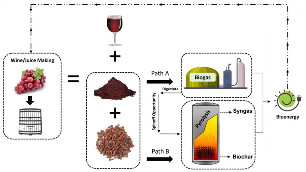
Biomass energy conversion encompasses the range of technological processes that transform organic materials, including forestry residues, agricultural by-products, energy crops, municipal organic waste, and industrial organic residues, into usable forms of energy such as electricity, heat, and biofuels, providing a sustainable and renewable alternative to fossil fuels while promoting circular economy practices and reducing environmental impact. These processes rely on the inherent chemical energy stored in biomass, which is released through various methods including direct combustion, co-firing, gasification, pyrolysis, anaerobic digestion, and fermentation, with the choice of technology determined by feedstock characteristics, moisture content, calorific value, and the intended application or scale of the energy system. Direct combustion remains the most widely implemented approach, particularly for solid biomass, where preprocessed materials such as wood chips, straw, husks, and pellets are burned in boilers to produce high-temperature flue gases that transfer heat to water or steam circulating through boiler tubes. The resulting pressurized steam drives turbines or engines to generate electricity, while residual thermal energy can be recovered for industrial process heat, district heating, or biomass pre-drying, significantly enhancing overall energy efficiency and reducing reliance on fossil fuels.
Gasification provides a more advanced conversion pathway, in which biomass is partially oxidized at high temperatures to produce syngas—a combustible mixture of hydrogen, carbon monoxide, methane, and carbon dioxide—that can be used in gas engines, turbines, or further processed into biofuels and chemicals. Syngas cleaning and conditioning systems are critical for removing particulates, tars, and other contaminants, ensuring safe and efficient operation of downstream equipment and maximizing energy yield. Pyrolysis, on the other hand, thermochemically decomposes biomass in the absence of oxygen to generate bio-oil, biochar, and syngas, offering flexibility for producing multiple energy carriers and value-added products. Anaerobic digestion converts organic waste into biogas through microbial activity in oxygen-free environments, producing methane-rich gas that can be combusted for heat and power or upgraded to biomethane for grid injection or transportation fuel. Fermentation is commonly applied to energy crops and sugar-rich biomass to produce ethanol and other liquid biofuels, providing additional pathways for renewable energy integration in transport and industrial applications.
Feedstock preprocessing is essential for efficient biomass energy conversion, as it standardizes particle size, reduces moisture content, improves fuel flow characteristics, and increases energy density, all of which contribute to stable combustion, higher thermal efficiency, and reduced operational issues such as slagging, fouling, or uneven heat distribution. Drying, grinding, shredding, pelletizing, and briquetting are typical preprocessing methods that enhance the usability of heterogeneous biomass feedstocks, allowing plants to operate continuously and reliably despite seasonal fluctuations and variations in feedstock quality. Co-firing strategies are often employed to blend different biomass types or combine biomass with fossil fuels, improving energy density, stabilizing combustion, and ensuring consistent electricity and heat generation. Advanced automation and real-time monitoring systems control critical operational parameters such as fuel feed rate, combustion or gasification temperature, oxygen concentration, steam pressure, and turbine or engine performance, optimizing energy production while maintaining safety and regulatory compliance.
Environmental management is integral to biomass energy conversion, as emissions from combustion and gasification processes can include nitrogen oxides, sulfur oxides, particulate matter, and volatile organic compounds. Modern plants implement comprehensive emission control technologies, including baghouse filters, electrostatic precipitators, scrubbers, and selective catalytic reduction systems, to minimize environmental impact and comply with strict regulatory standards. Combustion residues, including ash, often contain valuable minerals like potassium, calcium, and phosphorus that can be repurposed as soil amendments, fertilizers, or construction materials, reinforcing circular economy principles and reducing waste disposal needs. Combined heat and power (CHP) integration ensures maximal utilization of feedstock energy, reduces fossil fuel consumption, lowers carbon emissions, and improves overall plant efficiency. Proper feedstock management, advanced conversion technologies, automated monitoring, and by-product utilization collectively enable biomass energy conversion systems to operate efficiently, sustainably, and economically, delivering renewable energy in multiple forms while supporting rural development, greenhouse gas mitigation, and long-term energy security.
Economically and socially, biomass energy conversion provides substantial benefits by creating additional revenue streams for farmers, foresters, municipalities, and industrial operators, reducing the environmental burden of organic waste, and promoting sustainable land and forest management practices. Modular and scalable designs allow deployment of small-scale community or farm-based facilities as well as large industrial plants supplying electricity, heat, and biofuels to regional grids. By integrating efficient feedstock preprocessing, optimized energy conversion technologies, CHP systems, emission controls, and residue valorization, biomass energy conversion systems deliver reliable, continuous, and environmentally responsible renewable energy. These systems transform low-value organic residues into high-value energy and bio-products, contributing to carbon mitigation, circular economy practices, rural economic growth, and long-term energy security while providing flexible and sustainable solutions for electricity, thermal energy, and fuel production from biomass resources.
Biomass energy conversion represents a critical component of renewable energy infrastructure, providing the means to transform diverse organic materials into electricity, thermal energy, and biofuels while simultaneously supporting environmental sustainability, resource efficiency, and the circular economy. This process harnesses the chemical energy stored in biomass, which includes agricultural residues such as straw, husks, stalks, and bagasse; forestry residues like sawdust, wood chips, and branches; energy crops specifically cultivated for fuel purposes; and municipal or industrial organic waste streams. Biomass energy conversion can be accomplished through multiple technological pathways including direct combustion, co-firing, gasification, pyrolysis, anaerobic digestion, and fermentation, with the choice of method dictated by feedstock type, moisture content, calorific value, and the intended application or scale of the plant. Direct combustion remains one of the most widely implemented approaches, where preprocessed biomass is burned in boilers to generate high-temperature flue gases that transfer heat to water or steam circulating in boiler tubes, producing pressurized steam to drive turbines for electricity generation while residual thermal energy is captured for industrial heating, district heating, or biomass pre-drying, thereby significantly improving overall energy efficiency and reducing reliance on fossil fuels.
Gasification offers a more advanced and efficient route for biomass energy conversion, where biomass is partially oxidized at elevated temperatures to produce syngas—a mixture of hydrogen, carbon monoxide, methane, and carbon dioxide—which can be used in gas engines, turbines, or further processed into biofuels and chemicals. The efficiency and reliability of gasification-based systems depend heavily on syngas cleaning and conditioning processes that remove tars, particulates, and other contaminants to protect downstream equipment and optimize energy production. Pyrolysis, another conversion pathway, thermochemically decomposes biomass in the absence of oxygen to produce bio-oil, syngas, and biochar, offering flexibility for producing multiple energy carriers and value-added products such as soil amendments or carbon sequestration materials. Anaerobic digestion and fermentation represent biochemical pathways for biomass conversion, where microorganisms break down organic matter in oxygen-free environments to produce biogas or liquid biofuels such as ethanol, creating additional renewable energy options for electricity, heat, and transport fuel while simultaneously managing organic waste streams.
Efficient feedstock preprocessing is essential for stable and effective biomass energy conversion, as raw biomass often has variable moisture content, particle size, and energy density, which can affect combustion stability, heat transfer efficiency, and operational reliability. Techniques such as drying, shredding, grinding, pelletizing, and briquetting standardize feedstock characteristics, improve handling and flow, increase energy density, and ensure continuous, efficient conversion. Co-firing strategies are frequently applied to blend different biomass types or combine biomass with fossil fuels to stabilize combustion, improve energy density, and maintain uninterrupted electricity and heat generation despite seasonal or regional fluctuations in feedstock supply. Advanced automation and real-time monitoring systems are critical to controlling operational parameters such as fuel feed rate, combustion or gasification temperature, oxygen concentration, steam pressure, and turbine or engine load, optimizing energy output, efficiency, and emissions performance while maintaining safe and stable operation.
Environmental management is a core element of biomass energy conversion, as combustion and gasification processes can produce emissions including nitrogen oxides, sulfur oxides, particulate matter, and volatile organic compounds. Modern biomass energy plants employ extensive flue gas cleaning systems such as baghouse filters, electrostatic precipitators, scrubbers, and selective catalytic reduction units to minimize emissions and comply with environmental regulations. Combustion residues, including ash, are often mineral-rich, containing potassium, calcium, and phosphorus, which can be reused as fertilizers, soil amendments, or construction materials, supporting circular economy principles and reducing waste disposal challenges. The integration of combined heat and power (CHP) systems ensures maximal utilization of feedstock energy, reduces fossil fuel dependency, lowers greenhouse gas emissions, and enhances overall plant efficiency. Automated feedstock handling, combustion monitoring, and residue management further improve operational reliability and allow biomass energy conversion systems to maintain consistent electricity and heat production even when feedstock properties vary.
Economically, biomass energy conversion delivers multiple benefits, transforming agricultural, forestry, and municipal residues into high-value energy while creating revenue streams for farmers, foresters, municipalities, and industries, reducing waste management costs, and promoting sustainable land and resource management practices. Modular and scalable designs allow deployment of small-scale community or farm-based systems as well as large industrial plants supplying electricity, thermal energy, and biofuels to regional grids, enabling flexible and locally adapted energy solutions. By integrating efficient feedstock preprocessing, optimized energy conversion technologies, CHP systems, emissions control, and by-product valorization, biomass energy conversion systems operate sustainably, reliably, and economically, transforming low-value or waste biomass into continuous electricity, heat, and bio-products, supporting carbon mitigation, circular economy development, rural economic growth, and long-term energy security while providing practical solutions for renewable energy production from organic resources.
Biomass energy conversion is a fundamental component of modern renewable energy strategies, focusing on transforming organic materials into electricity, thermal energy, and biofuels in ways that maximize efficiency, sustainability, and economic value. This process encompasses a wide array of feedstocks, including agricultural residues such as straw, corn stover, husks, and sugarcane bagasse; forestry by-products like sawdust, wood chips, and branches; energy crops cultivated specifically for fuel purposes; municipal organic waste; and industrial biomass residues, all of which contain chemical energy that can be released through controlled conversion. The technologies employed range from direct combustion in fluidized-bed or moving-grate boilers, which generate high-temperature flue gases to produce steam for electricity and heat, to advanced gasification systems that produce syngas for use in turbines, engines, or chemical synthesis. Pyrolysis allows the production of bio-oil, syngas, and biochar, while biochemical pathways such as anaerobic digestion and fermentation convert organic matter into methane-rich biogas or ethanol, providing flexible options for electricity, heating, and fuel production depending on feedstock characteristics, moisture content, calorific value, and plant scale. These processes ensure that the energy content of biomass is utilized fully, with residual heat captured for industrial processes, district heating, or pre-drying biomass, significantly improving overall efficiency and reducing reliance on fossil fuels.
Effective biomass energy conversion requires rigorous feedstock preprocessing to overcome variability in moisture, particle size, and energy content that can negatively affect combustion, gasification, or fermentation efficiency. Techniques such as drying, shredding, grinding, pelletizing, and briquetting standardize the feedstock, improve energy density, facilitate smooth handling, and allow for stable, continuous operation. Co-firing strategies, where different biomass types or biomass-fossil fuel blends are used, enhance energy density, stabilize combustion, and ensure consistent electricity and thermal output despite seasonal variations in feedstock supply. Advanced monitoring and automation systems play a crucial role in controlling fuel feed rates, combustion temperatures, oxygen levels, steam pressure, and turbine or engine performance, optimizing energy production, maximizing fuel efficiency, and maintaining regulatory compliance while ensuring safe and stable plant operation.
Environmental management is a critical aspect of biomass energy conversion, as the processes can generate emissions including nitrogen oxides, sulfur oxides, particulate matter, and volatile organic compounds. Modern facilities employ comprehensive flue gas treatment systems such as baghouse filters, electrostatic precipitators, scrubbers, and selective catalytic reduction technologies to minimize environmental impact and meet stringent emission standards. Ash residues from combustion often contain valuable minerals such as potassium, calcium, and phosphorus, which can be reused as fertilizers, soil amendments, or construction materials, promoting circular economy principles and reducing waste disposal requirements. Integration of combined heat and power (CHP) systems further increases the efficiency of biomass conversion by capturing waste heat from electricity generation and using it for industrial heating or district heating, reducing overall fuel consumption, lowering carbon emissions, and ensuring the maximum utilization of feedstock energy. Automated feedstock handling, monitoring, and residue management systems enhance operational reliability, allowing continuous and stable energy production even when feedstock characteristics fluctuate.
Economically, biomass energy conversion provides substantial benefits by creating new revenue streams from agricultural, forestry, and municipal residues while reducing waste management costs and promoting sustainable land and forest management. Modular and scalable plant designs make biomass energy systems adaptable for small community-scale or farm-based applications as well as large industrial-scale facilities supplying electricity, heat, and biofuels to regional grids, ensuring flexibility to meet varying energy demands. By combining efficient feedstock preprocessing, advanced conversion technologies, CHP integration, emissions control, and by-product valorization, biomass energy conversion systems operate efficiently, sustainably, and reliably, transforming low-value organic materials into high-value energy and bio-products. These systems contribute to greenhouse gas mitigation, rural economic development, circular economy practices, and long-term energy security while providing a practical, renewable, and environmentally responsible solution for electricity, heat, and fuel production from diverse biomass resources.
Biomass energy conversion is a cornerstone of renewable energy development, encompassing the transformation of diverse organic feedstocks into electricity, heat, and biofuels while simultaneously supporting environmental sustainability, resource efficiency, and economic value creation. The feedstocks used in biomass energy conversion include agricultural residues such as straw, corn stover, sugarcane bagasse, and husks; forestry by-products like wood chips, sawdust, and branches; energy crops specifically grown for fuel purposes; municipal organic waste; and industrial biomass residues, all of which contain chemical energy that can be harnessed through controlled technological processes. The conversion pathways are numerous and adaptable, ranging from direct combustion in moving-grate or fluidized-bed boilers to advanced thermochemical and biochemical processes such as gasification, pyrolysis, anaerobic digestion, and fermentation. Direct combustion remains widely utilized, where preprocessed biomass is burned to produce high-temperature flue gases that heat water or generate steam, which then drives turbines or engines for electricity production while the residual thermal energy is recovered for industrial heating, district heating, or biomass pre-drying, thereby maximizing energy efficiency and reducing dependency on fossil fuels.
Gasification represents an advanced conversion method in which biomass is partially oxidized under controlled conditions to produce syngas—a mixture of hydrogen, carbon monoxide, methane, and carbon dioxide—which can be combusted in engines, turbines, or further processed into biofuels and chemicals. The efficiency and performance of gasification systems depend heavily on syngas cleaning and conditioning, which removes tars, particulates, and other contaminants to protect downstream equipment and optimize energy yield. Pyrolysis thermochemically decomposes biomass in the absence of oxygen to produce bio-oil, syngas, and biochar, enabling the generation of multiple energy carriers and value-added products. Anaerobic digestion and fermentation processes convert organic matter into methane-rich biogas or ethanol, offering renewable energy for electricity, heating, and transportation while managing organic waste streams. The integration of these conversion pathways allows biomass energy systems to be tailored to the characteristics of feedstock, energy demand, and local environmental conditions, ensuring flexibility, resilience, and high overall energy efficiency.
Efficient feedstock management is essential to biomass energy conversion, as raw biomass often exhibits significant variability in moisture content, particle size, and calorific value, which can affect combustion stability, heat transfer, and operational reliability. Preprocessing techniques such as drying, grinding, shredding, pelletizing, and briquetting standardize feedstock characteristics, improve energy density, facilitate smooth feeding into conversion units, and allow continuous, stable operation. Co-firing strategies, in which multiple biomass types or biomass-fossil fuel blends are used, further stabilize combustion, increase energy density, and maintain uninterrupted electricity and heat generation even with seasonal feedstock variability. Advanced automation and real-time monitoring systems regulate fuel feed rates, combustion or gasification temperatures, oxygen concentration, steam pressure, and turbine or engine output, optimizing energy production, efficiency, and emissions performance while ensuring operational safety and reliability.
Environmental management is a central aspect of biomass energy conversion, as combustion and gasification processes generate emissions such as nitrogen oxides, sulfur oxides, particulate matter, and volatile organic compounds. Modern plants employ comprehensive emission control technologies including baghouse filters, electrostatic precipitators, scrubbers, and selective catalytic reduction systems to minimize pollutants and comply with strict regulatory standards. Ash residues from biomass combustion are often mineral-rich, containing potassium, phosphorus, and calcium, and can be reused as fertilizers, soil amendments, or construction materials, supporting circular economy practices and reducing waste disposal requirements. The integration of combined heat and power (CHP) systems maximizes energy utilization by capturing waste heat from electricity generation for industrial processes, district heating, or biomass drying, reducing fuel consumption, lowering greenhouse gas emissions, and increasing the overall efficiency of biomass energy systems. Automated feedstock handling, combustion monitoring, and residue management further enhance reliability, allowing plants to maintain consistent electricity and heat production even under variable feedstock conditions.
Economically, biomass energy conversion provides significant benefits by transforming agricultural, forestry, and municipal residues into valuable energy while creating revenue streams for farmers, foresters, municipalities, and industrial operators, reducing waste management costs, and promoting sustainable land and resource management. Modular and scalable designs make biomass energy systems suitable for small community-scale or farm-based applications as well as large industrial plants supplying electricity, heat, and biofuels to regional grids, providing flexibility for diverse energy needs. By integrating advanced feedstock preprocessing, optimized energy conversion technologies, CHP systems, emissions control, and residue valorization, biomass energy conversion systems operate efficiently, sustainably, and reliably, turning low-value organic materials into continuous, high-value electricity, thermal energy, and bio-products. These systems support carbon mitigation, circular economy practices, rural economic development, and long-term energy security while providing practical, renewable, and environmentally responsible solutions for electricity, heat, and fuel production from a wide variety of biomass resources.
Biomass Thermal Power Plant
A biomass thermal power plant is a sophisticated renewable energy facility designed to convert the chemical energy stored in organic materials into electricity and thermal energy through controlled combustion or gasification processes, providing a sustainable alternative to fossil fuel-based power generation while promoting environmental sustainability, resource efficiency, and economic value creation. The plant relies on a wide range of feedstocks, including agricultural residues like sugarcane bagasse, corn stover, rice husks, and straw; forestry by-products such as wood chips, sawdust, and branches; energy crops cultivated specifically for fuel purposes; municipal organic waste; and industrial biomass residues. By utilizing these materials, which would otherwise be underutilized or disposed of through environmentally harmful methods, biomass thermal power plants not only generate renewable energy but also reduce greenhouse gas emissions, minimize open-field burning, and mitigate the environmental burden of organic waste accumulation.
The operation of a biomass thermal power plant typically begins with the collection, transportation, and preprocessing of feedstock to ensure uniform particle size, moisture content, and energy density. Preprocessing techniques such as drying, shredding, grinding, pelletizing, or briquetting are applied to enhance fuel handling, improve combustion stability, and increase energy efficiency. Once prepared, biomass is fed into boilers or furnaces where it undergoes controlled combustion, producing high-temperature flue gases that transfer heat to water circulating in boiler tubes. The resulting pressurized steam drives turbines or engines, converting thermal energy into electricity. The residual heat, which would otherwise be lost in conventional electricity-only power generation, can be recovered for industrial heating processes, district heating, or biomass pre-drying, significantly increasing overall plant efficiency. Advanced designs may also employ fluidized-bed, moving-grate, or suspension-fired boilers to accommodate heterogeneous feedstocks and optimize combustion, ensuring stable energy production even when feedstock characteristics vary.
Biomass thermal power plants often integrate combined heat and power (CHP) systems to maximize energy utilization by capturing waste heat from electricity generation and using it for heating applications, industrial processes, or preheating incoming biomass, which enhances energy efficiency and reduces overall fuel consumption. Co-firing with multiple biomass types or supplementary fossil fuels can further stabilize combustion, improve energy density, and maintain continuous operation despite seasonal feedstock variability. Sophisticated automation and real-time monitoring systems control critical operational parameters such as fuel feed rate, combustion temperature, oxygen concentration, steam pressure, and turbine load, optimizing electricity and thermal output while maintaining operational safety and regulatory compliance. These systems dynamically respond to fluctuations in feedstock properties and energy demand, ensuring reliable, consistent, and efficient performance under a wide range of operating conditions.
Environmental management is a key component of biomass thermal power plant operation, as combustion and gasification processes produce emissions such as nitrogen oxides, sulfur oxides, particulate matter, and volatile organic compounds. To address these challenges, modern plants implement advanced flue gas cleaning technologies including baghouse filters, electrostatic precipitators, scrubbers, and selective catalytic reduction units, reducing environmental impact and ensuring compliance with strict emissions regulations. Ash residues generated during combustion are often mineral-rich, containing potassium, calcium, and phosphorus, which can be repurposed as fertilizers, soil amendments, or construction materials, supporting circular economy principles and reducing waste disposal requirements. By effectively managing emissions, residues, and waste heat, biomass thermal power plants deliver renewable energy in a responsible and environmentally sustainable manner, while minimizing the ecological footprint of energy production.
Economically, biomass thermal power plants offer substantial advantages by transforming agricultural, forestry, and municipal residues into electricity and thermal energy, creating revenue streams for farmers, foresters, municipalities, and industrial operators, and reducing the costs associated with organic waste disposal. Modular and scalable designs allow deployment of small-scale community or farm-based systems as well as large industrial plants supplying electricity and heat to regional grids, enabling flexible energy solutions tailored to local demand. By integrating efficient feedstock preprocessing, optimized thermal and electrical conversion technologies, CHP integration, emissions control, and residue valorization, biomass thermal power plants operate as reliable, flexible, and sustainable energy systems. These facilities convert low-value organic residues into high-value electricity, heat, and by-products, contributing to greenhouse gas mitigation, circular economy practices, rural economic development, and long-term energy security while providing a practical, renewable, and environmentally responsible approach to electricity and thermal energy production from biomass resources.
Biomass thermal power plants are advanced renewable energy facilities that convert the chemical energy contained in organic feedstocks into electricity and thermal energy through controlled combustion or thermochemical conversion, providing a reliable and environmentally sustainable alternative to fossil fuel-based power generation. These plants are capable of processing a wide range of biomass materials, including agricultural residues such as sugarcane bagasse, rice husks, straw, corn stover, and other crop by-products; forestry residues including wood chips, sawdust, branches, and bark; energy crops grown specifically for fuel; municipal organic waste; and industrial biomass residues from food processing, paper manufacturing, and other industrial processes. By utilizing these resources, which might otherwise be discarded or burned openly, biomass thermal power plants reduce greenhouse gas emissions, prevent environmental pollution, support sustainable waste management, and contribute to carbon-neutral energy production while creating value from previously underutilized materials.
The operational process of a biomass thermal power plant begins with the collection, transportation, and preprocessing of feedstock to ensure uniformity in moisture content, particle size, and energy density, all of which are critical for efficient combustion and stable operation. Preprocessing methods such as drying, shredding, grinding, pelletizing, or briquetting improve fuel handling, increase calorific density, and optimize combustion efficiency while minimizing operational challenges like slagging, fouling, or uneven heat distribution. Once prepared, biomass is fed into specially designed boilers or furnaces, such as fluidized-bed, moving-grate, or suspension-fired boilers, where it undergoes controlled combustion to generate high-temperature flue gases. These gases transfer heat to water circulating in boiler tubes, producing pressurized steam that drives turbines or engines for electricity generation, while the residual thermal energy is captured and redirected for industrial heating, district heating, or biomass pre-drying, ensuring maximum utilization of energy content and improving the overall efficiency of the plant.
Biomass thermal power plants frequently integrate combined heat and power (CHP) systems to capitalize on waste heat from electricity production, providing a dual output of thermal energy and electricity that increases overall energy efficiency and reduces fuel consumption. Co-firing with multiple types of biomass or with small amounts of fossil fuel can enhance combustion stability, increase energy density, and ensure uninterrupted power generation even when feedstock availability fluctuates seasonally or regionally. Modern plants rely on sophisticated automation and real-time monitoring systems that regulate fuel feed rates, combustion temperatures, oxygen concentration, steam pressure, and turbine or engine load, optimizing electricity and thermal outputs, ensuring operational safety, and maintaining regulatory compliance. These systems also allow the plant to adapt dynamically to variations in feedstock properties, energy demand, and environmental conditions, maintaining reliable, continuous, and efficient energy production.
Environmental management is a central concern for biomass thermal power plants, as combustion and gasification processes produce emissions including nitrogen oxides, sulfur oxides, particulate matter, and volatile organic compounds. To mitigate these effects, modern facilities are equipped with advanced flue gas cleaning technologies such as baghouse filters, electrostatic precipitators, scrubbers, and selective catalytic reduction units that significantly reduce pollutants and ensure compliance with stringent environmental regulations. The ash generated during combustion is often rich in minerals such as potassium, calcium, and phosphorus and can be reused as fertilizer, soil amendment, or in construction materials, contributing to circular economy principles and minimizing waste disposal requirements. By integrating waste heat recovery, emissions control, and residue utilization, biomass thermal power plants provide a renewable energy solution that is both environmentally responsible and resource-efficient.
From an economic perspective, biomass thermal power plants offer multiple benefits by converting agricultural, forestry, and municipal residues into electricity and thermal energy, creating additional revenue streams for farmers, foresters, municipalities, and industrial operators while reducing costs associated with waste management. Modular and scalable designs allow deployment at small-scale, community-based, or farm-level facilities as well as large industrial-scale plants that feed electricity and heat into regional grids, providing flexibility to meet diverse energy demands. By combining efficient feedstock preprocessing, optimized thermal and electrical energy conversion, CHP integration, emission control, and by-product valorization, biomass thermal power plants operate as reliable, flexible, and sustainable energy systems. These plants transform low-value or waste biomass into high-value electricity, heat, and mineral-rich residues, contributing to greenhouse gas reduction, circular economy development, rural economic growth, and long-term energy security while offering practical, renewable, and environmentally responsible solutions for sustainable energy production.
Biomass thermal power plants are highly sophisticated renewable energy facilities that convert the chemical energy stored in organic materials into electricity and heat through controlled combustion or thermochemical processes, providing a reliable, sustainable, and environmentally responsible alternative to conventional fossil fuel power generation. These plants are capable of utilizing a wide spectrum of biomass feedstocks, including agricultural residues such as sugarcane bagasse, rice husks, corn stover, straw, and other crop by-products, forestry residues like wood chips, sawdust, branches, and bark, energy crops cultivated specifically for fuel purposes, municipal organic waste, and industrial biomass residues generated by food processing, paper manufacturing, and other industrial activities. By harnessing these materials, which might otherwise be discarded, landfilled, or burned in open fields, biomass thermal power plants reduce greenhouse gas emissions, mitigate environmental pollution, and promote sustainable waste management practices while simultaneously generating high-value energy outputs that support carbon-neutral energy objectives.
The operation of a biomass thermal power plant begins with the collection, transportation, and preprocessing of feedstocks to ensure uniformity in moisture content, particle size, and energy density, all of which are crucial for achieving stable combustion and optimal energy conversion. Preprocessing techniques such as drying, grinding, shredding, pelletizing, or briquetting improve fuel handling, increase calorific density, and enhance overall thermal efficiency while minimizing operational issues such as slagging, fouling, or uneven heat transfer. Once prepared, the biomass is fed into specially designed boilers or furnaces, including fluidized-bed, moving-grate, or suspension-fired systems, where it undergoes controlled combustion to produce high-temperature flue gases. These gases transfer thermal energy to water or steam circulating in boiler tubes, generating pressurized steam that drives turbines or engines to produce electricity, while the residual heat is recovered for industrial heating, district heating, or pre-drying of incoming biomass, maximizing overall energy efficiency and ensuring that nearly all of the feedstock’s energy content is effectively utilized.
Biomass thermal power plants frequently incorporate combined heat and power (CHP) systems, allowing simultaneous production of electricity and thermal energy from the same feedstock, which significantly increases overall plant efficiency and reduces fuel consumption. Co-firing strategies, in which multiple types of biomass or supplementary fossil fuels are blended, can stabilize combustion, enhance energy density, and ensure continuous operation despite seasonal or regional fluctuations in feedstock availability. Advanced automation and real-time monitoring systems play a vital role in controlling critical operational parameters such as fuel feed rates, combustion temperature, oxygen levels, steam pressure, and turbine or engine performance, optimizing both electrical and thermal outputs while ensuring safe operation and compliance with environmental regulations. These systems also enable the plant to dynamically adjust to variations in feedstock properties, energy demand, and environmental conditions, maintaining reliable, continuous, and high-efficiency energy production under diverse operational scenarios.
Environmental management is an integral aspect of biomass thermal power plant operation, as combustion and thermochemical processes produce emissions including nitrogen oxides, sulfur oxides, particulate matter, and volatile organic compounds. Modern plants are equipped with advanced emission control technologies, including baghouse filters, electrostatic precipitators, scrubbers, and selective catalytic reduction units, which minimize environmental impact and ensure adherence to stringent regulatory standards. The ash produced during biomass combustion is often mineral-rich, containing potassium, phosphorus, calcium, and other nutrients, which can be repurposed as fertilizers, soil amendments, or construction materials, further promoting circular economy practices and reducing waste disposal challenges. By efficiently integrating flue gas cleaning, waste heat recovery, and residue utilization, biomass thermal power plants deliver renewable energy in an environmentally responsible and resource-efficient manner.
Economically, biomass thermal power plants offer numerous benefits by transforming agricultural, forestry, and municipal residues into electricity and thermal energy, creating new revenue streams for farmers, foresters, municipalities, and industrial operators while reducing the costs associated with waste management and disposal. Modular and scalable designs allow deployment at small, community-scale or farm-level facilities as well as large industrial plants that feed electricity and heat into regional grids, providing versatile solutions for a wide range of energy demands. Through efficient feedstock preprocessing, optimized thermal and electrical energy conversion, CHP integration, emissions control, and by-product valorization, biomass thermal power plants operate as reliable, sustainable, and flexible energy systems. These plants convert low-value or waste biomass into high-value electricity, heat, and mineral-rich residues, contributing to greenhouse gas reduction, circular economy development, rural economic growth, and long-term energy security while providing practical, renewable, and environmentally responsible solutions for continuous and sustainable energy production from diverse biomass resources.
Biomass thermal power plants represent a vital segment of renewable energy infrastructure, focusing on the conversion of organic materials into electricity and thermal energy while promoting sustainability, resource efficiency, and environmental responsibility. These plants utilize a broad array of feedstocks, including agricultural residues such as rice husks, corn stover, sugarcane bagasse, straw, and other crop by-products; forestry residues like wood chips, sawdust, bark, and branches; energy crops grown specifically for fuel; municipal organic waste; and industrial biomass residues from food processing, paper manufacturing, and other industrial operations. By effectively converting these otherwise underutilized or waste materials into high-value energy, biomass thermal power plants reduce greenhouse gas emissions, minimize the environmental impact of open-field burning or landfill disposal, and contribute to carbon-neutral energy production while creating economic opportunities for farmers, foresters, municipalities, and industries.
The operational workflow of biomass thermal power plants begins with the collection, transportation, and preprocessing of feedstock to achieve uniform moisture content, particle size, and energy density, all of which are critical for stable combustion and optimal energy efficiency. Preprocessing methods, including drying, grinding, shredding, pelletizing, and briquetting, improve fuel handling, increase calorific density, enhance combustion stability, and reduce operational issues such as slagging, fouling, or uneven heat transfer. Once prepared, biomass is fed into specially engineered boilers or furnaces, including moving-grate, fluidized-bed, or suspension-fired systems, where controlled combustion produces high-temperature flue gases. These gases transfer heat to water or steam circulating in boiler tubes, generating pressurized steam to drive turbines or engines for electricity production, while residual heat is recovered for industrial processes, district heating, or pre-drying of incoming biomass. This integration of electricity and heat recovery maximizes the overall efficiency of the plant and ensures nearly complete utilization of the energy content of the feedstock.
Many biomass thermal power plants employ combined heat and power (CHP) systems to simultaneously generate electricity and usable thermal energy, significantly improving overall energy conversion efficiency and reducing the need for additional fuel inputs. Co-firing multiple types of biomass or combining biomass with small amounts of fossil fuel can further stabilize combustion, improve energy density, and ensure continuous, reliable operation even when feedstock availability varies seasonally or geographically. Modern facilities rely on advanced automation and real-time monitoring systems to regulate key operational parameters such as fuel feed rate, combustion temperature, oxygen concentration, steam pressure, and turbine or engine performance. These systems optimize electricity and thermal output, maintain operational safety, and ensure compliance with strict environmental regulations, while dynamically adjusting to changes in feedstock characteristics, energy demand, and external environmental conditions, ensuring consistent and reliable energy production under a wide range of scenarios.
Environmental management is a critical aspect of biomass thermal power plant operation, as the combustion and thermochemical processes produce emissions including nitrogen oxides, sulfur oxides, particulate matter, and volatile organic compounds. To address these challenges, modern biomass plants are equipped with comprehensive flue gas cleaning technologies, including baghouse filters, electrostatic precipitators, scrubbers, and selective catalytic reduction units, effectively minimizing pollutant emissions and ensuring compliance with regulatory standards. The ash produced during biomass combustion is often rich in minerals such as potassium, calcium, and phosphorus, which can be repurposed as fertilizers, soil amendments, or construction materials, supporting circular economy practices and reducing the need for waste disposal. The careful integration of flue gas treatment, waste heat recovery, and residue management ensures that biomass thermal power plants operate in an environmentally responsible manner while maintaining high efficiency and reliability.
From an economic perspective, biomass thermal power plants create significant value by converting agricultural, forestry, and municipal residues into electricity and thermal energy, generating additional revenue streams for farmers, foresters, municipalities, and industrial operators while reducing costs associated with waste management and disposal. The plants can be designed in modular and scalable configurations, making them suitable for small-scale community or farm-based installations as well as large industrial facilities supplying electricity and heat to regional grids, providing flexibility to meet diverse energy needs. By integrating effective feedstock preprocessing, optimized thermal and electrical energy conversion technologies, CHP systems, emission control, and by-product utilization, biomass thermal power plants operate as highly efficient, flexible, and sustainable energy systems. These plants transform low-value or waste biomass into high-value electricity, heat, and mineral-rich residues, supporting greenhouse gas mitigation, circular economy development, rural economic growth, and long-term energy security while offering practical, renewable, and environmentally responsible solutions for continuous energy production from a wide variety of biomass resources.
Biomass Renewable Energy
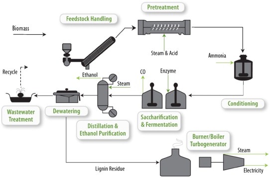
Biomass renewable energy is a critical sector of the global renewable energy landscape, offering a sustainable, carbon-neutral alternative to conventional fossil fuel-based power generation by converting organic materials into electricity, heat, and biofuels. This form of energy utilizes a wide variety of biomass feedstocks, including agricultural residues such as sugarcane bagasse, rice husks, corn stover, straw, and other crop by-products; forestry residues like wood chips, sawdust, bark, and branches; energy crops cultivated specifically for fuel purposes; municipal organic waste; and industrial biomass residues generated by food processing, paper production, and other industrial processes. By using these materials, which would otherwise be discarded, burned openly, or sent to landfills, biomass renewable energy not only provides a dependable source of energy but also mitigates greenhouse gas emissions, reduces environmental pollution, promotes sustainable waste management, and contributes to carbon neutrality.
The conversion of biomass into renewable energy can be achieved through a variety of technological pathways, including direct combustion, co-firing, gasification, pyrolysis, anaerobic digestion, and fermentation, with the selection of method depending on feedstock type, moisture content, energy density, and the intended end use. Direct combustion in specially designed boilers, such as fluidized-bed or moving-grate systems, remains the most widely implemented method, where processed biomass is burned to generate high-temperature flue gases that heat water or steam circulating in boiler tubes. The resulting pressurized steam drives turbines or engines for electricity generation, while residual thermal energy can be recovered for industrial heating, district heating, or pre-drying incoming biomass, ensuring maximum energy efficiency and utilization. Gasification offers an advanced approach, partially oxidizing biomass to produce syngas, a mixture of hydrogen, carbon monoxide, methane, and carbon dioxide, which can be combusted in engines, turbines, or further refined into biofuels and chemicals, while pyrolysis thermochemically decomposes biomass in the absence of oxygen to yield bio-oil, syngas, and biochar, offering multiple energy carriers and valuable by-products.
Efficient feedstock management is central to biomass renewable energy production, as raw biomass typically has variable moisture content, particle size, and calorific value, which can impact combustion stability, heat transfer, and overall energy conversion efficiency. Preprocessing techniques such as drying, grinding, shredding, pelletizing, and briquetting standardize feedstock characteristics, increase energy density, and facilitate smooth handling, ensuring continuous and reliable operation. Co-firing strategies, which blend different biomass types or supplement biomass with small amounts of fossil fuel, further stabilize combustion, improve energy density, and ensure uninterrupted electricity and heat generation, even when feedstock supply fluctuates seasonally or regionally. Advanced automation and real-time monitoring systems regulate fuel feed rates, combustion temperatures, oxygen levels, steam pressure, and turbine or engine load, optimizing energy production while maintaining operational safety, regulatory compliance, and environmental performance.
Environmental management is a critical aspect of biomass renewable energy, as combustion and thermochemical processes can produce nitrogen oxides, sulfur oxides, particulate matter, and volatile organic compounds. Modern biomass energy facilities implement comprehensive flue gas cleaning technologies, including baghouse filters, electrostatic precipitators, scrubbers, and selective catalytic reduction systems, to minimize emissions and comply with strict environmental standards. Ash and other combustion residues are often rich in minerals such as potassium, calcium, and phosphorus, which can be repurposed as fertilizers, soil amendments, or construction materials, supporting circular economy practices and reducing waste disposal requirements. By integrating emissions control, waste heat recovery, and residue valorization, biomass renewable energy systems operate efficiently, sustainably, and with minimal environmental impact.
Economically, biomass renewable energy provides significant benefits by transforming agricultural, forestry, and municipal residues into valuable electricity, heat, and biofuels, creating revenue streams for farmers, foresters, municipalities, and industrial operators while reducing costs associated with waste management. Modular and scalable plant designs allow deployment of small-scale, community-based, or farm-level systems as well as large industrial plants supplying electricity and thermal energy to regional grids, offering flexibility to meet diverse energy needs. By combining efficient feedstock preprocessing, optimized energy conversion technologies, combined heat and power systems, emissions control, and residue utilization, biomass renewable energy facilities operate as reliable, flexible, and sustainable energy systems. These systems convert low-value or waste biomass into high-value electricity, heat, and by-products, contributing to greenhouse gas mitigation, circular economy development, rural economic growth, and long-term energy security, while offering practical, renewable, and environmentally responsible solutions for continuous energy production from a wide variety of biomass resources.
Biomass renewable energy is an increasingly important component of the global transition toward sustainable and carbon-neutral energy systems, utilizing the chemical energy stored in organic materials to produce electricity, heat, and biofuels while reducing reliance on fossil fuels and mitigating greenhouse gas emissions. The range of feedstocks suitable for biomass renewable energy is extensive, including agricultural residues such as sugarcane bagasse, rice husks, corn stover, wheat straw, and other crop by-products, forestry residues including wood chips, sawdust, bark, branches, and other logging by-products, energy crops cultivated specifically for fuel purposes, municipal organic waste, and industrial biomass residues from sectors like food processing, paper production, and agro-industrial manufacturing. By converting these materials, which might otherwise be discarded or incinerated in uncontrolled conditions, biomass renewable energy facilities not only provide reliable power and heat but also contribute to sustainable waste management, reduction of environmental pollution, and the creation of local economic opportunities for farmers, foresters, municipalities, and industrial operators.
The technological pathways for biomass renewable energy conversion are diverse and adaptable, encompassing direct combustion, co-firing, gasification, pyrolysis, anaerobic digestion, and fermentation processes. Direct combustion remains a widely applied method in which processed biomass is burned in advanced boilers such as fluidized-bed, moving-grate, or suspension-fired systems to generate high-temperature flue gases that transfer heat to water or steam in boiler tubes, producing pressurized steam that drives turbines or engines for electricity generation while the residual heat is recovered for district heating, industrial processes, or biomass pre-drying. Gasification provides an efficient thermochemical approach, converting biomass into syngas—a mixture of hydrogen, carbon monoxide, methane, and carbon dioxide—that can be combusted in engines or turbines or refined into biofuels and chemicals, whereas pyrolysis thermally decomposes biomass in the absence of oxygen to produce bio-oil, syngas, and biochar, offering multiple energy products and high-value by-products. Biochemical processes such as anaerobic digestion and fermentation convert organic matter into biogas or ethanol, providing renewable fuels for electricity, heat, and transportation while managing organic waste streams effectively.
Effective feedstock management is critical to maximizing the efficiency and stability of biomass renewable energy systems, as raw biomass typically varies in moisture content, particle size, and calorific value, which can influence combustion stability, heat transfer, and overall energy conversion efficiency. Preprocessing techniques, including drying, shredding, grinding, pelletizing, and briquetting, standardize feedstock properties, improve energy density, facilitate smooth feeding, and allow continuous, stable plant operation. Co-firing multiple biomass types or combining biomass with supplementary fossil fuels can stabilize combustion, increase energy density, and ensure uninterrupted electricity and thermal energy production even when feedstock supply fluctuates seasonally or regionally. Advanced automation and real-time monitoring systems regulate critical operational parameters such as fuel feed rate, combustion or gasification temperature, oxygen concentration, steam pressure, and turbine or engine output, optimizing both electricity and thermal energy generation while maintaining operational safety, efficiency, and compliance with environmental regulations.
Environmental management is a central aspect of biomass renewable energy, as combustion, gasification, and other conversion processes can generate nitrogen oxides, sulfur oxides, particulate matter, and volatile organic compounds. Modern biomass energy facilities employ comprehensive flue gas treatment technologies, including baghouse filters, electrostatic precipitators, scrubbers, and selective catalytic reduction systems, to minimize emissions and ensure adherence to strict environmental standards. Ash and other combustion residues often contain valuable minerals such as potassium, phosphorus, and calcium, which can be reused as fertilizers, soil amendments, or construction materials, supporting circular economy practices and reducing the need for waste disposal. By integrating efficient emissions control, waste heat recovery, and residue valorization, biomass renewable energy systems deliver energy in an environmentally responsible and resource-efficient manner while maintaining high operational reliability and performance.
From an economic and strategic perspective, biomass renewable energy generates multiple benefits by transforming agricultural, forestry, and municipal residues into electricity, thermal energy, and biofuels, creating revenue streams for farmers, foresters, municipalities, and industries while reducing the costs and environmental impact of organic waste disposal. Modular and scalable plant designs allow for deployment at small-scale, community-level, or farm-based facilities, as well as large industrial plants supplying electricity and heat to regional grids, offering flexibility to meet diverse energy demands. By combining efficient feedstock preprocessing, advanced thermochemical and biochemical conversion technologies, combined heat and power systems, emissions control, and by-product utilization, biomass renewable energy facilities operate as reliable, flexible, and sustainable energy systems. These systems transform low-value or waste biomass into high-value electricity, heat, and mineral-rich residues, supporting greenhouse gas mitigation, circular economy development, rural economic growth, and long-term energy security, providing practical, renewable, and environmentally responsible solutions for continuous energy production from a wide variety of biomass resources.
Biomass renewable energy is a vital component of modern energy systems, focusing on the conversion of organic materials into electricity, thermal energy, and biofuels through processes that are both sustainable and environmentally responsible. This form of energy harnesses a broad spectrum of feedstocks, including agricultural residues like sugarcane bagasse, corn stover, rice husks, straw, and other crop by-products, forestry residues such as wood chips, sawdust, bark, and branches, energy crops specifically cultivated for fuel purposes, municipal organic waste, and industrial biomass residues from food processing, paper manufacturing, and other industrial activities. Utilizing these materials not only provides a dependable source of renewable energy but also mitigates greenhouse gas emissions, reduces the environmental impact of uncontrolled waste disposal or open burning, and contributes to a circular economy by creating value from materials that would otherwise go unused.
The technological pathways for converting biomass into renewable energy are diverse, including direct combustion, co-firing, gasification, pyrolysis, anaerobic digestion, and fermentation, with the choice of technology depending on the type of feedstock, moisture content, energy density, and desired energy output. Direct combustion remains widely implemented, where preprocessed biomass is burned in advanced boilers such as fluidized-bed, moving-grate, or suspension-fired systems to generate high-temperature flue gases, which then transfer heat to water or steam in boiler tubes, producing pressurized steam that drives turbines or engines for electricity generation. Residual heat from these systems can be recovered for industrial processes, district heating, or biomass pre-drying, improving overall efficiency and maximizing energy utilization. Gasification converts biomass into syngas—a mixture of hydrogen, carbon monoxide, methane, and carbon dioxide—that can be used in engines, turbines, or refined into biofuels, while pyrolysis decomposes biomass thermally in the absence of oxygen to produce bio-oil, syngas, and biochar, enabling multiple energy carriers and high-value by-products. Biochemical processes such as anaerobic digestion and fermentation convert organic matter into biogas or ethanol, which can be used for electricity, heating, or transportation fuels, adding versatility to biomass renewable energy systems.
Efficient feedstock management is essential for biomass renewable energy, as raw biomass typically exhibits variability in moisture content, particle size, and calorific value, which can impact combustion stability, heat transfer, and energy conversion efficiency. Preprocessing steps such as drying, grinding, shredding, pelletizing, and briquetting standardize feedstock properties, increase energy density, improve fuel handling, and allow continuous, reliable operation. Co-firing strategies, which blend multiple biomass types or combine biomass with small amounts of fossil fuel, can enhance combustion stability, increase energy density, and ensure uninterrupted electricity and heat production even when feedstock availability varies seasonally or regionally. Advanced automation and real-time monitoring systems regulate critical operational parameters such as fuel feed rates, combustion temperature, oxygen levels, steam pressure, and turbine or engine load, optimizing energy production while maintaining operational safety, regulatory compliance, and environmental performance.
Environmental management is a critical focus of biomass renewable energy, as combustion, gasification, and other conversion processes can generate nitrogen oxides, sulfur oxides, particulate matter, and volatile organic compounds. Modern biomass energy facilities employ advanced flue gas treatment technologies, including baghouse filters, electrostatic precipitators, scrubbers, and selective catalytic reduction units, to minimize emissions and ensure compliance with stringent environmental regulations. Ash and other residues produced during biomass conversion are often rich in minerals such as potassium, calcium, and phosphorus, which can be repurposed as fertilizers, soil amendments, or construction materials, promoting circular economy practices and reducing waste disposal requirements. By integrating emissions control, waste heat recovery, and residue utilization, biomass renewable energy systems operate efficiently, sustainably, and with minimal environmental impact, while maintaining reliable and continuous energy production.
Economically, biomass renewable energy provides significant advantages by transforming agricultural, forestry, and municipal residues into electricity, thermal energy, and biofuels, creating revenue streams for farmers, foresters, municipalities, and industrial operators, and reducing costs associated with waste management. Modular and scalable plant designs allow implementation at small-scale, community-based, or farm-level facilities, as well as at large industrial plants supplying electricity and heat to regional grids, offering flexibility to meet diverse energy demands. By combining efficient feedstock preprocessing, advanced thermochemical and biochemical conversion technologies, combined heat and power systems, emissions control, and by-product valorization, biomass renewable energy facilities operate as reliable, flexible, and sustainable energy systems. These systems transform low-value or waste biomass into high-value electricity, thermal energy, and mineral-rich residues, supporting greenhouse gas reduction, circular economy development, rural economic growth, and long-term energy security while providing practical, renewable, and environmentally responsible solutions for continuous and efficient energy production from diverse biomass resources.
Biomass renewable energy represents a cornerstone of sustainable energy development, focusing on the transformation of organic materials into electricity, heat, and biofuels through environmentally responsible processes that reduce dependence on fossil fuels and lower greenhouse gas emissions. This type of energy generation harnesses a wide variety of feedstocks, including agricultural residues such as sugarcane bagasse, rice husks, corn stover, wheat straw, and other crop by-products; forestry residues including wood chips, sawdust, bark, branches, and logging by-products; energy crops cultivated specifically for fuel purposes; municipal organic waste; and industrial biomass residues from food processing, paper production, and other industrial sectors. By using these materials, which would otherwise be discarded, burned in open fields, or sent to landfills, biomass renewable energy systems provide reliable and sustainable power while contributing to waste management, environmental protection, and the promotion of a circular economy that recycles materials back into productive use.
The conversion of biomass into renewable energy can be achieved through multiple technological pathways, each adapted to the specific characteristics of the feedstock and the desired energy output. Direct combustion is the most widespread method, where preprocessed biomass is burned in advanced boilers such as fluidized-bed, moving-grate, or suspension-fired systems to produce high-temperature flue gases. These gases transfer heat to water or steam circulating in boiler tubes, generating pressurized steam that drives turbines or engines to produce electricity, while residual heat is recovered for industrial processes, district heating, or pre-drying of incoming biomass, maximizing overall energy efficiency. Gasification provides a thermochemical pathway, converting biomass into syngas composed of hydrogen, carbon monoxide, methane, and carbon dioxide, which can be combusted in engines or turbines or further refined into biofuels and chemicals. Pyrolysis thermally decomposes biomass in the absence of oxygen, producing bio-oil, syngas, and biochar, allowing for the simultaneous generation of multiple energy carriers and valuable by-products. Biochemical processes, including anaerobic digestion and fermentation, convert organic matter into biogas or ethanol, which can be utilized for electricity, heating, or transportation fuels, further diversifying the renewable energy output from biomass resources.
Effective feedstock management is critical to ensuring stable and efficient biomass renewable energy production, as raw biomass typically exhibits variable moisture content, particle size, and calorific value, which can affect combustion stability, heat transfer, and overall conversion efficiency. Preprocessing techniques such as drying, grinding, shredding, pelletizing, and briquetting standardize feedstock properties, increase energy density, improve handling, and support continuous, reliable plant operation. Co-firing strategies that combine multiple biomass types or mix biomass with small amounts of fossil fuel can stabilize combustion, enhance energy density, and maintain uninterrupted electricity and thermal production even when feedstock supply fluctuates seasonally or regionally. Advanced automation and real-time monitoring systems play a central role in regulating critical parameters such as fuel feed rate, combustion temperature, oxygen concentration, steam pressure, and turbine or engine load, optimizing energy output, maintaining operational safety, and ensuring environmental compliance. These systems allow the plant to dynamically adjust to changes in feedstock characteristics, energy demand, and external conditions, ensuring consistent, high-efficiency energy production.
Environmental management is an essential aspect of biomass renewable energy systems, as combustion, gasification, and other conversion processes generate emissions including nitrogen oxides, sulfur oxides, particulate matter, and volatile organic compounds. Modern biomass facilities incorporate advanced emission control technologies such as baghouse filters, electrostatic precipitators, scrubbers, and selective catalytic reduction units to minimize environmental impact and meet stringent regulatory standards. Ash and other residues from biomass conversion are often mineral-rich, containing potassium, phosphorus, calcium, and other nutrients, and can be repurposed as fertilizers, soil amendments, or construction materials, supporting circular economy practices and reducing waste disposal needs. By integrating emission control, waste heat recovery, and residue valorization, biomass renewable energy systems operate efficiently and sustainably, providing high-value energy while minimizing environmental footprint.
From an economic standpoint, biomass renewable energy offers substantial advantages by converting agricultural, forestry, and municipal residues into electricity, thermal energy, and biofuels, creating revenue streams for farmers, foresters, municipalities, and industrial operators while reducing costs related to waste disposal. Modular and scalable plant designs enable deployment at small, community-level, or farm-based facilities as well as at large industrial plants supplying electricity and heat to regional grids, offering flexibility to meet diverse energy requirements. By combining efficient feedstock preprocessing, advanced thermochemical and biochemical conversion technologies, combined heat and power integration, emissions control, and by-product utilization, biomass renewable energy facilities operate as reliable, flexible, and sustainable energy systems. These systems transform low-value or waste biomass into high-value electricity, heat, and mineral-rich residues, contributing to greenhouse gas mitigation, circular economy development, rural economic growth, and long-term energy security, providing practical, renewable, and environmentally responsible solutions for continuous and efficient energy production from diverse biomass resources.
Biomass Energy Plant

A biomass energy plant is a specialized facility designed to convert organic materials into electricity, heat, and sometimes biofuels through processes that are both sustainable and environmentally responsible, providing a renewable alternative to fossil fuel-based power generation while contributing to greenhouse gas reduction and resource efficiency. These plants are capable of utilizing a wide variety of biomass feedstocks, including agricultural residues such as sugarcane bagasse, rice husks, corn stover, straw, and other crop by-products; forestry residues like wood chips, sawdust, bark, and branches; energy crops specifically grown for fuel; municipal organic waste; and industrial biomass residues from food processing, paper manufacturing, and other industries. By transforming these materials, which would otherwise be discarded, landfilled, or burned in open fields, biomass energy plants provide a reliable energy source while supporting sustainable waste management, environmental protection, and the development of a circular economy.
The operational process of a biomass energy plant involves collection, transportation, and preprocessing of feedstock to ensure uniform moisture content, particle size, and energy density, which are critical for efficient and stable energy conversion. Preprocessing techniques include drying, shredding, grinding, pelletizing, or briquetting, which improve fuel handling, increase calorific value, and optimize combustion performance while reducing operational issues such as slagging, fouling, or uneven heat transfer. The prepared biomass is then fed into specialized boilers, furnaces, or gasifiers—such as fluidized-bed, moving-grate, or suspension-fired systems—where controlled combustion or thermochemical conversion produces high-temperature flue gases. These gases transfer heat to water or steam circulating in boiler tubes, generating pressurized steam that drives turbines or engines to produce electricity, while residual heat is recovered for industrial processes, district heating, or pre-drying of incoming biomass, ensuring maximum energy utilization and plant efficiency.
Many biomass energy plants integrate combined heat and power (CHP) systems, which allow simultaneous generation of electricity and usable thermal energy, significantly improving overall efficiency and reducing fuel consumption. Co-firing multiple biomass types or supplementing with small amounts of fossil fuel can stabilize combustion, improve energy density, and maintain uninterrupted operation even when feedstock availability varies seasonally or regionally. Advanced automation and real-time monitoring systems control fuel feed rates, combustion temperatures, oxygen concentration, steam pressure, and turbine or engine load, optimizing energy output while maintaining safety, reliability, and compliance with environmental regulations. These systems dynamically adjust to changes in feedstock characteristics, energy demand, and environmental conditions, ensuring continuous, stable, and high-efficiency energy production.
Environmental management is a crucial aspect of biomass energy plants, as combustion and thermochemical processes can produce nitrogen oxides, sulfur oxides, particulate matter, and volatile organic compounds. Modern facilities use advanced emission control technologies such as baghouse filters, electrostatic precipitators, scrubbers, and selective catalytic reduction systems to minimize pollutants and meet stringent regulatory standards. Ash and other residues produced during biomass conversion are often rich in minerals like potassium, calcium, and phosphorus, which can be repurposed as fertilizers, soil amendments, or construction materials, further supporting circular economy practices and reducing waste disposal requirements. By integrating flue gas cleaning, waste heat recovery, and residue utilization, biomass energy plants provide renewable energy in an environmentally responsible, resource-efficient, and sustainable manner.
Economically, biomass energy plants create significant value by transforming agricultural, forestry, and municipal residues into electricity, thermal energy, and biofuels, generating revenue for farmers, foresters, municipalities, and industrial operators while reducing the costs associated with waste disposal. Modular and scalable designs allow deployment at small-scale, community-based, or farm-level facilities as well as large industrial plants supplying energy to regional grids, offering flexibility to meet varying energy demands. By combining efficient feedstock preprocessing, optimized thermal and electrical energy conversion technologies, CHP integration, emissions control, and by-product valorization, biomass energy plants operate as reliable, flexible, and sustainable energy systems. These facilities convert low-value or waste biomass into high-value electricity, heat, and mineral-rich residues, contributing to greenhouse gas mitigation, circular economy development, rural economic growth, and long-term energy security while providing practical, renewable, and environmentally responsible energy solutions.
Biomass energy plants are advanced facilities dedicated to the conversion of organic materials into electricity, heat, and in some cases biofuels, providing a renewable and environmentally sustainable alternative to fossil fuel-based energy. These plants make use of a diverse range of feedstocks, including agricultural residues such as rice husks, sugarcane bagasse, corn stover, wheat straw, and other crop by-products, forestry residues like wood chips, bark, sawdust, and branches, energy crops specifically grown for fuel purposes, municipal organic waste, and industrial biomass residues from food processing, paper production, and other industries. By utilizing these materials, which would otherwise be discarded, burned in open areas, or sent to landfills, biomass energy plants reduce greenhouse gas emissions, support sustainable waste management practices, and create economic opportunities for farmers, foresters, municipalities, and industrial operators while simultaneously producing reliable energy outputs.
The operational workflow of a biomass energy plant begins with the collection, transportation, and preprocessing of feedstock to ensure uniformity in moisture content, particle size, and energy density, all of which are critical to maintaining efficient and stable energy conversion. Preprocessing techniques such as drying, shredding, grinding, pelletizing, and briquetting enhance fuel handling, increase calorific value, and improve combustion performance, while reducing operational challenges like slagging, fouling, and uneven heat distribution. Once prepared, biomass is fed into specialized boilers, furnaces, or gasifiers, including moving-grate, fluidized-bed, or suspension-fired systems, where controlled combustion or thermochemical conversion generates high-temperature flue gases. These gases transfer heat to water or steam in boiler tubes, producing pressurized steam that drives turbines or engines to generate electricity, while residual heat is captured for industrial applications, district heating, or pre-drying of incoming biomass, ensuring maximum energy utilization and high plant efficiency.
Many biomass energy plants operate as combined heat and power (CHP) facilities, simultaneously producing electricity and useful thermal energy, which greatly enhances overall energy efficiency and reduces fuel consumption. Co-firing strategies, which blend different types of biomass or include small amounts of fossil fuel, can stabilize combustion, increase energy density, and maintain uninterrupted operation even when feedstock availability fluctuates seasonally or geographically. Modern biomass plants incorporate sophisticated automation and real-time monitoring systems to regulate fuel feed rates, combustion temperature, oxygen levels, steam pressure, and turbine or engine load, optimizing electricity and heat production while ensuring operational safety, reliability, and compliance with environmental regulations. These intelligent systems allow the plant to dynamically respond to changes in feedstock properties, energy demand, and environmental conditions, providing consistent and efficient energy production under all operating circumstances.
Environmental management is a critical component of biomass energy plants, as combustion and thermochemical conversion processes generate emissions such as nitrogen oxides, sulfur oxides, particulate matter, and volatile organic compounds. To address these concerns, modern facilities employ advanced emission control technologies including baghouse filters, electrostatic precipitators, scrubbers, and selective catalytic reduction units, effectively minimizing pollutants and maintaining regulatory compliance. Ash and other residues from biomass conversion are often rich in minerals like potassium, phosphorus, and calcium, which can be repurposed as fertilizers, soil amendments, or construction materials, promoting circular economy principles and reducing waste disposal requirements. By integrating efficient emissions control, waste heat recovery, and residue management, biomass energy plants operate sustainably, offering a renewable energy solution that is environmentally responsible and resource-efficient.
From an economic and strategic perspective, biomass energy plants provide numerous benefits by transforming low-value or waste biomass into electricity, thermal energy, and biofuels, creating revenue streams for agricultural producers, foresters, municipalities, and industrial operators, while reducing the cost of waste management and disposal. Modular and scalable designs enable deployment at small, community-level or farm-scale facilities as well as large industrial plants that supply electricity and heat to regional grids, offering flexibility to meet a wide range of energy needs. By combining effective feedstock preprocessing, optimized energy conversion technologies, CHP systems, emissions control, and by-product utilization, biomass energy plants function as reliable, sustainable, and flexible energy systems. These facilities convert otherwise low-value or discarded biomass into high-value electricity, thermal energy, and mineral-rich residues, supporting greenhouse gas reduction, circular economy development, rural economic growth, and long-term energy security, providing practical, renewable, and environmentally responsible solutions for continuous energy production from diverse biomass resources.
Biomass energy plants are critical infrastructures in the renewable energy landscape, designed to convert organic materials into electricity, thermal energy, and sometimes biofuels through processes that are both sustainable and environmentally responsible. These plants utilize an extensive range of feedstocks, including agricultural residues such as sugarcane bagasse, rice husks, corn stover, wheat straw, and other crop by-products; forestry residues including wood chips, bark, sawdust, and branches; energy crops cultivated specifically for fuel purposes; municipal organic waste; and industrial biomass residues from food processing, paper production, and other manufacturing operations. By transforming these materials, which might otherwise be discarded, incinerated in open fields, or sent to landfills, biomass energy plants contribute to reducing greenhouse gas emissions, promoting sustainable waste management, and supporting a circular economy that converts low-value materials into high-value energy, all while creating economic opportunities for farmers, foresters, municipalities, and industrial operators.
The operational process of a biomass energy plant involves several critical steps, beginning with the collection, transportation, and preprocessing of feedstock to ensure consistency in moisture content, particle size, and energy density. These factors are essential to achieving stable combustion and efficient energy conversion. Preprocessing techniques such as drying, shredding, grinding, pelletizing, and briquetting enhance fuel handling, improve calorific value, and optimize combustion performance, while reducing operational issues like slagging, fouling, or uneven heat distribution. Once prepared, the biomass is fed into specialized boilers, furnaces, or gasifiers, including moving-grate, fluidized-bed, or suspension-fired systems, where controlled combustion or thermochemical conversion generates high-temperature flue gases. These gases transfer heat to water or steam circulating in boiler tubes, producing pressurized steam that drives turbines or engines for electricity generation, while residual heat is captured for industrial processes, district heating, or pre-drying of incoming biomass, ensuring maximum energy utilization and plant efficiency.
Many biomass energy plants integrate combined heat and power (CHP) systems to simultaneously produce electricity and useful thermal energy, which significantly enhances overall plant efficiency and reduces fuel consumption. Co-firing strategies, which blend multiple biomass types or supplement biomass with small amounts of fossil fuel, can stabilize combustion, improve energy density, and ensure uninterrupted operation even when feedstock supply fluctuates seasonally or regionally. Advanced automation and real-time monitoring systems are central to modern biomass plant operation, regulating fuel feed rates, combustion temperature, oxygen levels, steam pressure, and turbine or engine load, optimizing energy output while maintaining operational safety and compliance with environmental standards. These systems enable the facility to dynamically adapt to variations in feedstock properties, energy demand, and environmental conditions, ensuring continuous, high-efficiency energy production under a wide range of operational scenarios.
Environmental management is a vital aspect of biomass energy plant operation, as combustion and thermochemical processes generate emissions including nitrogen oxides, sulfur oxides, particulate matter, and volatile organic compounds. Modern facilities employ advanced emission control technologies such as baghouse filters, electrostatic precipitators, scrubbers, and selective catalytic reduction systems to minimize environmental impact and comply with strict regulations. Ash and other residues from biomass conversion are typically rich in minerals such as potassium, calcium, and phosphorus, which can be repurposed as fertilizers, soil amendments, or construction materials, further supporting circular economy principles and reducing waste disposal requirements. By integrating emissions control, waste heat recovery, and residue utilization, biomass energy plants operate as environmentally responsible, resource-efficient, and sustainable energy systems.
Economically, biomass energy plants provide significant value by converting agricultural, forestry, and municipal residues into electricity, thermal energy, and biofuels, creating new revenue streams for farmers, foresters, municipalities, and industrial operators while lowering costs associated with waste management. Modular and scalable plant designs allow deployment at small, community-level or farm-based facilities as well as large industrial plants supplying electricity and heat to regional grids, offering flexibility to meet a variety of energy needs. By combining effective feedstock preprocessing, optimized thermochemical and biochemical conversion technologies, CHP integration, emissions control, and by-product utilization, biomass energy plants function as reliable, flexible, and sustainable energy systems. These facilities transform low-value or discarded biomass into high-value electricity, heat, and mineral-rich residues, supporting greenhouse gas reduction, circular economy development, rural economic growth, and long-term energy security while providing practical, renewable, and environmentally responsible energy solutions from diverse biomass resources.
Biomass energy plants are essential components of modern renewable energy strategies, designed to convert organic materials into electricity, heat, and biofuels through processes that are both environmentally sustainable and economically viable. These plants can utilize a wide variety of biomass feedstocks, including agricultural residues such as sugarcane bagasse, corn stover, rice husks, wheat straw, and other crop by-products, as well as forestry residues like wood chips, sawdust, bark, and branches, energy crops grown specifically for fuel purposes, municipal organic waste, and industrial biomass residues generated from food processing, paper production, and other manufacturing operations. By repurposing these materials that would otherwise be discarded, incinerated in open fields, or sent to landfills, biomass energy plants help reduce greenhouse gas emissions, prevent environmental pollution, promote sustainable waste management practices, and support the circular economy by converting low-value or waste biomass into high-value energy while generating economic opportunities for farmers, foresters, municipalities, and industrial operators.
The operational workflow of biomass energy plants begins with the collection, transportation, and preprocessing of feedstock to achieve uniformity in moisture content, particle size, and calorific value, all of which are critical for efficient and stable energy conversion. Preprocessing techniques, including drying, shredding, grinding, pelletizing, and briquetting, improve fuel handling, enhance energy density, and optimize combustion performance while mitigating operational challenges such as slagging, fouling, and uneven heat distribution. Once prepared, the biomass is fed into boilers, furnaces, or gasifiers, including moving-grate, fluidized-bed, or suspension-fired systems, where controlled combustion or thermochemical conversion produces high-temperature flue gases. These gases transfer heat to water or steam circulating in boiler tubes, generating pressurized steam that drives turbines or engines to produce electricity, while residual heat can be recovered for district heating, industrial processes, or pre-drying incoming biomass, ensuring maximum efficiency and comprehensive utilization of energy content.
Many biomass energy plants employ combined heat and power (CHP) systems, allowing simultaneous generation of electricity and useful thermal energy, which significantly enhances overall plant efficiency and reduces fuel consumption. Co-firing strategies, where multiple biomass types are blended or small amounts of fossil fuel are used, stabilize combustion, increase energy density, and ensure uninterrupted operation even when feedstock availability fluctuates due to seasonal or regional factors. Modern plants rely heavily on advanced automation and real-time monitoring systems to regulate fuel feed rates, combustion temperatures, oxygen levels, steam pressure, and turbine or engine output, optimizing electricity and heat generation while maintaining operational safety and environmental compliance. These intelligent systems allow the facility to dynamically adjust to changes in feedstock characteristics, energy demand, and environmental conditions, ensuring consistent, high-efficiency, and reliable energy production.
Environmental management is a core aspect of biomass energy plant operation, as combustion and thermochemical processes can produce nitrogen oxides, sulfur oxides, particulate matter, and volatile organic compounds. To mitigate these impacts, modern facilities integrate advanced emission control technologies such as baghouse filters, electrostatic precipitators, scrubbers, and selective catalytic reduction systems, effectively minimizing pollutants and complying with strict environmental regulations. Ash and other residues generated from biomass conversion are often rich in minerals such as potassium, calcium, and phosphorus, which can be recycled as fertilizers, soil amendments, or construction materials, promoting circular economy practices and reducing the need for landfill disposal. By combining emissions control, waste heat recovery, and residue valorization, biomass energy plants achieve environmentally responsible and resource-efficient operation while maintaining high energy output and reliability.
From an economic and strategic perspective, biomass energy plants deliver significant benefits by converting agricultural, forestry, and municipal residues into electricity, thermal energy, and biofuels, creating new revenue streams for farmers, foresters, municipalities, and industrial operators while lowering waste management costs. Modular and scalable plant designs allow deployment at small community-level or farm-based facilities, as well as at large industrial plants supplying electricity and heat to regional grids, providing flexibility to meet diverse energy demands. By integrating efficient feedstock preprocessing, advanced thermochemical and biochemical conversion technologies, CHP systems, emissions control, and by-product utilization, biomass energy plants operate as reliable, flexible, and sustainable energy systems. These facilities transform low-value or discarded biomass into high-value electricity, heat, and mineral-rich residues, supporting greenhouse gas reduction, circular economy development, rural economic growth, and long-term energy security, offering practical, renewable, and environmentally responsible solutions for continuous energy production from a wide array of biomass resources.
Biomass Electricity Production
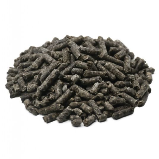
Biomass electricity production is a vital segment of renewable energy generation, utilizing organic materials as a sustainable fuel source to generate power while reducing reliance on fossil fuels and minimizing environmental impact. This process encompasses a wide range of feedstocks, including agricultural residues such as sugarcane bagasse, corn stover, rice husks, wheat straw, and other crop by-products, forestry residues like wood chips, sawdust, bark, and branches, energy crops specifically cultivated for fuel purposes, municipal organic waste, and industrial biomass residues from sectors like food processing, paper manufacturing, and other industrial activities. By converting these materials into electricity, biomass energy plants not only provide a continuous and reliable energy supply but also contribute to waste management, greenhouse gas mitigation, and circular economy initiatives by transforming low-value or discarded biomass into high-value energy resources.
The production of electricity from biomass involves several critical stages, beginning with the collection, transport, and preprocessing of the feedstock to ensure uniformity in moisture content, particle size, and calorific value. Preprocessing techniques such as drying, shredding, grinding, pelletizing, and briquetting optimize the fuel characteristics, improve combustion performance, and facilitate efficient handling, thereby reducing operational challenges like uneven heat distribution, slagging, or fouling. Once prepared, the biomass is fed into specialized boilers, furnaces, or gasifiers—such as moving-grate, fluidized-bed, or suspension-fired systems—where controlled combustion or thermochemical conversion produces high-temperature flue gases. These gases transfer heat to water or steam in boiler tubes, generating pressurized steam that drives turbines or engines for electricity generation. In advanced systems, residual thermal energy is captured for district heating, industrial processes, or pre-drying incoming biomass, improving overall energy efficiency and maximizing resource utilization.
Combined heat and power (CHP) integration is a common feature in biomass electricity production, enabling simultaneous generation of electricity and usable thermal energy, which significantly improves the overall efficiency of the plant. Co-firing strategies, which involve blending different types of biomass or supplementing with small amounts of fossil fuels, help stabilize combustion, increase energy density, and maintain uninterrupted electricity production even when feedstock supply fluctuates due to seasonal or regional factors. Modern biomass power plants rely heavily on sophisticated automation and real-time monitoring systems to regulate fuel feed rates, combustion temperatures, oxygen levels, steam pressure, and turbine load, optimizing electricity output while ensuring operational safety, reliability, and compliance with environmental standards. These systems allow the plant to adapt dynamically to variations in feedstock properties and energy demand, ensuring continuous and efficient electricity production.
Environmental management is a central concern in biomass electricity production, as combustion and thermochemical processes generate emissions such as nitrogen oxides, sulfur oxides, particulate matter, and volatile organic compounds. To address these issues, contemporary biomass facilities incorporate advanced flue gas cleaning technologies, including baghouse filters, electrostatic precipitators, scrubbers, and selective catalytic reduction units, minimizing pollutants and ensuring compliance with strict environmental regulations. Ash and other residues from biomass conversion are often rich in minerals like potassium, calcium, and phosphorus and can be repurposed as fertilizers, soil amendments, or construction materials, supporting circular economy practices and reducing waste disposal needs. By integrating emission control, waste heat recovery, and residue valorization, biomass electricity plants operate in a sustainable, environmentally responsible, and resource-efficient manner.
Economically, biomass electricity production provides substantial benefits by converting low-value or waste biomass into electricity, generating revenue streams for farmers, foresters, municipalities, and industrial operators while reducing costs associated with waste management and disposal. Modular and scalable plant designs allow deployment at small-scale, community-level, or farm-based facilities, as well as at large industrial plants supplying electricity to regional grids, providing flexibility to meet diverse energy demands. By combining effective feedstock preprocessing, advanced thermochemical and biochemical conversion technologies, CHP integration, emissions control, and by-product utilization, biomass electricity plants function as reliable, flexible, and sustainable energy systems. These facilities transform agricultural, forestry, and municipal residues into high-value electricity, heat, and mineral-rich by-products, contributing to greenhouse gas reduction, circular economy development, rural economic growth, and long-term energy security, offering practical, renewable, and environmentally responsible solutions for continuous electricity production from diverse biomass resources.
Biomass electricity production represents a key pillar in the transition toward renewable and sustainable energy, converting a wide range of organic materials into electricity while simultaneously providing environmental, economic, and social benefits. Biomass feedstocks include agricultural residues such as sugarcane bagasse, corn stover, wheat straw, rice husks, and other crop by-products, forestry residues including wood chips, bark, sawdust, and branches, energy crops specifically cultivated for fuel purposes, municipal organic waste, and industrial biomass residues from food processing, paper manufacturing, and other industrial sectors. By transforming these materials into electricity, biomass power plants not only provide a reliable energy source but also contribute to waste management, reduce methane and carbon dioxide emissions from decomposition or open burning, and support circular economy practices by turning otherwise low-value or discarded biomass into a high-value, renewable energy product, creating additional revenue streams for farmers, foresters, municipalities, and industrial operators.
The process of generating electricity from biomass involves multiple stages, starting with collection, transportation, and preprocessing of feedstock to ensure uniform moisture content, particle size, and energy density, which are critical to maintaining stable and efficient energy conversion. Preprocessing methods such as drying, shredding, grinding, pelletizing, and briquetting improve the energy density, facilitate fuel handling, and optimize combustion performance, while reducing operational issues such as slagging, fouling, or uneven heat distribution. Once preprocessed, biomass is fed into boilers, furnaces, or gasifiers, including fluidized-bed, moving-grate, or suspension-fired systems, where controlled combustion or thermochemical conversion produces high-temperature flue gases. These flue gases transfer heat to water or steam circulating in boiler tubes, generating pressurized steam that drives turbines or engines for electricity production, while residual heat can be recovered for industrial processes, district heating, or pre-drying of incoming biomass, maximizing energy utilization and overall plant efficiency.
Many biomass electricity plants employ combined heat and power (CHP) systems to simultaneously generate electricity and useful thermal energy, which significantly enhances overall efficiency and reduces fuel consumption. Co-firing strategies, which blend multiple biomass types or supplement biomass with small amounts of fossil fuel, stabilize combustion, increase energy density, and allow for uninterrupted operation even when feedstock supply fluctuates seasonally or regionally. Advanced automation and real-time monitoring systems play a central role in regulating fuel feed rates, combustion temperatures, oxygen levels, steam pressure, and turbine load, optimizing electricity generation while ensuring operational safety, reliability, and compliance with environmental regulations. These systems enable the plant to respond dynamically to variations in feedstock properties, energy demand, and external conditions, providing consistent and efficient electricity output under a wide range of operational scenarios.
Environmental management is a critical aspect of biomass electricity production, as combustion and thermochemical conversion processes produce emissions such as nitrogen oxides, sulfur oxides, particulate matter, and volatile organic compounds. To mitigate these emissions, modern biomass plants are equipped with advanced flue gas treatment technologies including baghouse filters, electrostatic precipitators, scrubbers, and selective catalytic reduction systems, ensuring compliance with stringent environmental standards and minimizing environmental impact. Ash and other residues generated during biomass conversion are often rich in minerals such as potassium, calcium, and phosphorus and can be repurposed as fertilizers, soil amendments, or construction materials, further enhancing circular economy benefits and reducing waste disposal requirements. By integrating emission control, waste heat recovery, and by-product valorization, biomass electricity plants operate sustainably, efficiently, and with minimal environmental footprint while providing continuous, high-quality energy.
From an economic perspective, biomass electricity production delivers substantial advantages by converting agricultural, forestry, and municipal residues into electricity, creating new revenue streams for rural communities, municipalities, and industrial operators while lowering waste management costs. Modular and scalable plant designs allow deployment at small, community-level, or farm-based facilities as well as large industrial plants supplying electricity to regional grids, providing flexibility to meet diverse energy needs. By combining efficient feedstock preprocessing, advanced thermochemical and biochemical conversion technologies, CHP systems, emissions control, and by-product utilization, biomass electricity plants function as reliable, flexible, and sustainable energy systems. These facilities transform low-value or discarded biomass into high-value electricity, heat, and mineral-rich residues, contributing to greenhouse gas reduction, circular economy development, rural economic growth, and long-term energy security while providing practical, renewable, and environmentally responsible solutions for continuous and efficient electricity production from diverse biomass resources.
Biomass electricity production is a central component of the global shift toward renewable energy, relying on the conversion of organic materials into electricity in a manner that is sustainable, environmentally responsible, and economically beneficial. This form of energy generation draws on a wide variety of feedstocks, including agricultural residues such as sugarcane bagasse, corn stover, rice husks, wheat straw, and other crop by-products, as well as forestry residues like wood chips, sawdust, bark, and branches. Additionally, energy crops cultivated specifically for fuel purposes, municipal organic waste, and industrial biomass residues from sectors such as food processing, paper manufacturing, and other industrial operations provide a continuous and diversified fuel source. Utilizing these materials not only provides a renewable energy supply but also mitigates greenhouse gas emissions from decomposition or open burning, reduces landfill use, supports sustainable waste management practices, and contributes to the circular economy by converting low-value biomass into high-value electricity, creating additional revenue streams for farmers, foresters, municipalities, and industrial operators.
The process of generating electricity from biomass encompasses multiple stages, beginning with the collection, transportation, and preprocessing of feedstock to ensure uniform moisture content, particle size, and calorific value, which are essential for efficient and stable energy conversion. Preprocessing techniques such as drying, shredding, grinding, pelletizing, and briquetting enhance fuel handling, increase energy density, and improve combustion performance while reducing operational challenges like uneven heat distribution, slagging, or fouling. Once prepared, biomass is fed into specialized boilers, furnaces, or gasifiers—including moving-grate, fluidized-bed, or suspension-fired systems—where controlled combustion or thermochemical conversion produces high-temperature flue gases. These gases transfer heat to water or steam circulating in boiler tubes, generating pressurized steam that drives turbines or engines to produce electricity, while residual heat can be recovered for district heating, industrial processes, or pre-drying of incoming biomass, maximizing energy efficiency and overall plant performance.
Many biomass electricity plants employ combined heat and power (CHP) systems to simultaneously produce electricity and useful thermal energy, significantly increasing overall efficiency and reducing fuel consumption. Co-firing strategies, which blend multiple biomass types or supplement biomass with small quantities of fossil fuels, stabilize combustion, increase energy density, and maintain uninterrupted operation even when feedstock supply fluctuates due to seasonal or regional factors. Advanced automation and real-time monitoring systems regulate fuel feed rates, combustion temperature, oxygen levels, steam pressure, and turbine load, optimizing electricity generation while maintaining operational safety, reliability, and environmental compliance. These systems allow the plant to adapt dynamically to changes in feedstock properties, energy demand, and environmental conditions, ensuring consistent, high-efficiency electricity production even under varying operational scenarios.
Environmental management is a critical aspect of biomass electricity production, as combustion and thermochemical conversion processes produce emissions including nitrogen oxides, sulfur oxides, particulate matter, and volatile organic compounds. Modern biomass plants mitigate these emissions through advanced flue gas treatment technologies, including baghouse filters, electrostatic precipitators, scrubbers, and selective catalytic reduction units, ensuring compliance with strict environmental standards and minimizing their ecological footprint. Ash and other residues generated from biomass conversion are often rich in minerals such as potassium, calcium, and phosphorus, which can be reused as fertilizers, soil amendments, or construction materials, further supporting circular economy principles and reducing waste disposal requirements. By integrating emission control, waste heat recovery, and by-product utilization, biomass electricity plants operate as environmentally responsible, resource-efficient, and sustainable energy systems.
Economically, biomass electricity production offers substantial benefits by converting agricultural, forestry, and municipal residues into electricity, creating new income opportunities for rural communities, municipalities, and industrial operators while reducing costs associated with waste management. Modular and scalable designs allow for deployment at small community-level or farm-based facilities as well as large industrial plants supplying electricity to regional grids, offering flexibility to meet varying energy needs. By combining efficient feedstock preprocessing, advanced thermochemical and biochemical conversion technologies, CHP systems, emissions control, and by-product valorization, biomass electricity plants function as reliable, flexible, and sustainable energy systems. These facilities transform low-value or discarded biomass into high-value electricity, thermal energy, and mineral-rich residues, supporting greenhouse gas reduction, circular economy development, rural economic growth, and long-term energy security while delivering practical, renewable, and environmentally responsible electricity generation from diverse biomass resources.
Biomass electricity production stands at the forefront of renewable energy technologies, transforming organic materials into a reliable and sustainable source of power that simultaneously addresses environmental, economic, and social objectives. Biomass feedstocks are diverse, encompassing agricultural residues such as sugarcane bagasse, corn stover, rice husks, wheat straw, and other crop by-products, forestry residues including wood chips, bark, sawdust, and branches, dedicated energy crops, municipal organic waste, and industrial biomass residues from food processing, paper manufacturing, and other industries. By converting these materials into electricity, biomass energy plants not only provide continuous power generation but also reduce greenhouse gas emissions that would result from decomposition or open-field burning, promote effective waste management practices, and support circular economy principles by turning low-value or discarded biomass into high-value energy resources, creating economic benefits for farmers, foresters, municipalities, and industrial operators alike.
The generation of electricity from biomass involves a carefully orchestrated process beginning with the collection, transport, and preprocessing of feedstock to achieve uniform moisture content, particle size, and calorific value, all of which are critical for stable and efficient energy conversion. Preprocessing methods such as drying, shredding, grinding, pelletizing, and briquetting enhance fuel handling, increase energy density, and optimize combustion performance while minimizing operational issues such as slagging, fouling, or uneven heat transfer. Once processed, the biomass is introduced into boilers, furnaces, or gasifiers—including moving-grate, fluidized-bed, or suspension-fired systems—where controlled combustion or thermochemical conversion produces high-temperature flue gases. These gases transfer heat to water or steam circulating in boiler tubes, generating pressurized steam that drives turbines or engines to produce electricity, while residual thermal energy can be captured for district heating, industrial processes, or pre-drying incoming biomass, ensuring maximum utilization of energy content and high overall plant efficiency.
Many biomass electricity plants are designed with combined heat and power (CHP) capabilities, enabling simultaneous production of electricity and usable thermal energy, which significantly increases plant efficiency and reduces fuel consumption. Co-firing approaches, blending different biomass types or supplementing biomass with small amounts of fossil fuel, help stabilize combustion, improve energy density, and maintain uninterrupted electricity generation even when feedstock supply fluctuates due to seasonal or regional variability. Modern biomass facilities utilize advanced automation and real-time monitoring systems to control fuel feed rates, combustion temperatures, oxygen levels, steam pressure, and turbine or engine load, optimizing electricity production while ensuring operational safety, reliability, and environmental compliance. These intelligent systems allow the plant to adapt dynamically to changes in feedstock characteristics, energy demand, and environmental conditions, maintaining continuous high-efficiency electricity generation across all operational scenarios.
Environmental considerations are a central concern in biomass electricity production, as combustion and thermochemical processes can produce nitrogen oxides, sulfur oxides, particulate matter, and volatile organic compounds. Contemporary plants incorporate sophisticated flue gas cleaning technologies, including baghouse filters, electrostatic precipitators, scrubbers, and selective catalytic reduction units, minimizing pollutants and ensuring compliance with stringent environmental regulations. Ash and other residues from biomass conversion are often rich in minerals such as potassium, calcium, and phosphorus, which can be repurposed as fertilizers, soil amendments, or construction materials, supporting sustainable resource management and circular economy initiatives. By combining emission control, waste heat recovery, and by-product valorization, biomass electricity plants operate efficiently and responsibly, providing renewable energy with minimal environmental impact.
From an economic standpoint, biomass electricity production creates substantial value by converting agricultural, forestry, and municipal residues into electricity, generating revenue for rural communities, municipalities, and industrial operators while reducing waste management costs. Modular and scalable plant designs allow deployment at small community-level or farm-based facilities as well as large industrial plants supplying electricity to regional grids, offering flexibility to meet diverse energy requirements. By integrating efficient feedstock preprocessing, advanced thermochemical and biochemical conversion technologies, CHP integration, emissions control, and by-product utilization, biomass electricity plants function as reliable, flexible, and sustainable energy systems. These facilities transform low-value or discarded biomass into high-value electricity, thermal energy, and nutrient-rich residues, contributing to greenhouse gas reduction, circular economy development, rural economic growth, and long-term energy security while providing practical, renewable, and environmentally responsible solutions for continuous electricity production from diverse biomass resources.
Biomass Power Generation
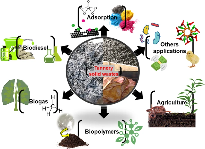
Biomass power generation is a pivotal technology in the renewable energy sector, focused on converting organic materials into electricity and, in many cases, useful thermal energy, providing a sustainable alternative to fossil fuel-based power systems while supporting environmental, economic, and social objectives. The feedstocks used for biomass power generation are highly diverse, including agricultural residues such as sugarcane bagasse, corn stover, rice husks, wheat straw, and other crop by-products, forestry residues like wood chips, sawdust, bark, and branches, energy crops specifically cultivated for fuel purposes, municipal organic waste, and industrial biomass residues from food processing, paper production, and other industrial operations. By utilizing these materials, which might otherwise be discarded, burned in open fields, or sent to landfills, biomass power plants reduce greenhouse gas emissions, contribute to sustainable waste management, and support circular economy practices by converting low-value biomass into high-value electricity and heat, creating additional revenue streams for farmers, foresters, municipalities, and industrial operators.
The operational process of biomass power generation begins with the collection, transportation, and preprocessing of feedstock to ensure uniformity in moisture content, particle size, and calorific value, all of which are critical for stable and efficient energy conversion. Preprocessing methods such as drying, shredding, grinding, pelletizing, and briquetting improve fuel handling, increase energy density, and optimize combustion performance while reducing operational problems like slagging, fouling, and uneven heat transfer. Once processed, the biomass is fed into boilers, furnaces, or gasifiers—including moving-grate, fluidized-bed, or suspension-fired systems—where controlled combustion or thermochemical conversion produces high-temperature flue gases. These flue gases transfer heat to water or steam circulating in boiler tubes, generating pressurized steam that drives turbines or engines to produce electricity, while residual thermal energy is often recovered for district heating, industrial processes, or pre-drying incoming biomass, ensuring maximum efficiency and resource utilization.
Many biomass power generation facilities employ combined heat and power (CHP) systems, allowing simultaneous production of electricity and useful thermal energy, significantly increasing overall plant efficiency and reducing fuel consumption. Co-firing strategies, which involve blending different biomass types or supplementing with small amounts of fossil fuel, help stabilize combustion, improve energy density, and maintain continuous electricity generation even when feedstock availability fluctuates due to seasonal or regional factors. Modern biomass plants also incorporate advanced automation and real-time monitoring systems to regulate fuel feed rates, combustion temperature, oxygen levels, steam pressure, and turbine or engine load, optimizing electricity production while ensuring operational safety, reliability, and compliance with environmental regulations. These intelligent control systems allow the plant to adapt dynamically to changes in feedstock characteristics, energy demand, and environmental conditions, ensuring consistent and efficient power generation across all operating conditions.
Environmental management is a central aspect of biomass power generation, as combustion and thermochemical processes produce emissions such as nitrogen oxides, sulfur oxides, particulate matter, and volatile organic compounds. To mitigate these impacts, modern facilities integrate advanced emission control technologies including baghouse filters, electrostatic precipitators, scrubbers, and selective catalytic reduction units, minimizing pollutants and ensuring compliance with strict environmental standards. Ash and other residues produced during biomass conversion are often rich in minerals like potassium, calcium, and phosphorus, which can be repurposed as fertilizers, soil amendments, or construction materials, supporting sustainable resource management and circular economy initiatives. By integrating emission control, waste heat recovery, and by-product utilization, biomass power generation facilities operate sustainably, providing renewable energy with minimal environmental impact while maximizing efficiency and reliability.
Economically, biomass power generation provides significant value by transforming agricultural, forestry, and municipal residues into electricity and thermal energy, creating revenue opportunities for rural communities, municipalities, and industrial operators while reducing the costs associated with waste management. Modular and scalable plant designs allow deployment at small, community-level or farm-based facilities as well as large industrial plants supplying electricity to regional grids, offering flexibility to meet a variety of energy demands. By combining efficient feedstock preprocessing, advanced thermochemical and biochemical conversion technologies, CHP integration, emissions control, and by-product valorization, biomass power generation facilities function as reliable, flexible, and sustainable energy systems. These plants transform low-value or discarded biomass into high-value electricity, thermal energy, and nutrient-rich residues, contributing to greenhouse gas mitigation, circular economy development, rural economic growth, and long-term energy security, providing practical, renewable, and environmentally responsible solutions for continuous and efficient power generation from diverse biomass resources.
Biomass power generation is an increasingly vital component of the global energy landscape, providing a renewable and sustainable method to produce electricity and thermal energy from organic materials while reducing dependence on fossil fuels and minimizing environmental impact. The feedstocks utilized in biomass power generation are diverse, encompassing agricultural residues such as sugarcane bagasse, corn stover, rice husks, wheat straw, and other crop by-products, forestry residues including wood chips, sawdust, bark, and branches, energy crops specifically cultivated for fuel purposes, municipal organic waste, and industrial biomass residues generated by food processing, paper manufacturing, and other industrial operations. By converting these materials, which would otherwise be discarded, burned openly, or sent to landfills, biomass power plants provide multiple environmental benefits, including reductions in greenhouse gas emissions, improved waste management, and support for circular economy practices by transforming low-value biomass into high-value energy while creating economic opportunities for farmers, foresters, municipalities, and industrial operators.
The process of biomass power generation involves several stages, beginning with the collection, transportation, and preprocessing of feedstock to achieve consistency in moisture content, particle size, and calorific value, all of which are essential for efficient and stable energy conversion. Preprocessing techniques such as drying, shredding, grinding, pelletizing, and briquetting improve fuel handling, increase energy density, and optimize combustion performance while reducing operational issues such as uneven heat distribution, slagging, or fouling. Once processed, the biomass is introduced into boilers, furnaces, or gasifiers—including moving-grate, fluidized-bed, or suspension-fired systems—where controlled combustion or thermochemical conversion produces high-temperature flue gases. These gases transfer heat to water or steam circulating in boiler tubes, generating pressurized steam that drives turbines or engines to produce electricity, while residual heat is often recovered for district heating, industrial processes, or pre-drying incoming biomass, ensuring maximum energy utilization and plant efficiency.
Many biomass power generation plants are designed with combined heat and power (CHP) capabilities, enabling simultaneous generation of electricity and useful thermal energy, which significantly increases overall efficiency and reduces fuel consumption. Co-firing strategies, which involve blending different biomass types or supplementing biomass with small amounts of fossil fuels, help stabilize combustion, increase energy density, and maintain continuous power generation even when feedstock availability fluctuates due to seasonal or regional variations. Modern biomass facilities employ advanced automation and real-time monitoring systems to regulate fuel feed rates, combustion temperatures, oxygen levels, steam pressure, and turbine or engine load, optimizing electricity output while ensuring operational safety, reliability, and environmental compliance. These intelligent systems allow the plant to dynamically adapt to variations in feedstock properties, energy demand, and environmental conditions, maintaining consistent, high-efficiency electricity production under a wide range of operational scenarios.
Environmental management is a critical concern in biomass power generation, as combustion and thermochemical processes produce emissions such as nitrogen oxides, sulfur oxides, particulate matter, and volatile organic compounds. To mitigate these effects, contemporary biomass plants integrate sophisticated flue gas treatment technologies, including baghouse filters, electrostatic precipitators, scrubbers, and selective catalytic reduction units, minimizing pollutants and ensuring compliance with strict environmental standards. Ash and other residues from biomass conversion are often rich in minerals such as potassium, calcium, and phosphorus, which can be repurposed as fertilizers, soil amendments, or construction materials, further supporting circular economy principles and reducing waste disposal requirements. By combining emissions control, waste heat recovery, and by-product valorization, biomass power generation facilities operate sustainably, efficiently, and with minimal environmental footprint while providing continuous, high-quality energy.
From an economic perspective, biomass power generation creates substantial value by transforming agricultural, forestry, and municipal residues into electricity and thermal energy, generating revenue for rural communities, municipalities, and industrial operators while reducing costs associated with waste management. Modular and scalable plant designs allow deployment at small, community-level or farm-based facilities, as well as large industrial plants supplying electricity to regional grids, providing flexibility to meet diverse energy needs. By integrating efficient feedstock preprocessing, advanced thermochemical and biochemical conversion technologies, CHP systems, emissions control, and by-product utilization, biomass power generation facilities function as reliable, flexible, and sustainable energy systems. These plants transform low-value or discarded biomass into high-value electricity, heat, and mineral-rich residues, contributing to greenhouse gas reduction, circular economy development, rural economic growth, and long-term energy security, offering practical, renewable, and environmentally responsible solutions for continuous power generation from a broad spectrum of biomass resources.
Biomass power generation has become a cornerstone of renewable energy development, offering a sustainable method for producing electricity and heat from organic materials while reducing reliance on fossil fuels and mitigating environmental impacts. The feedstocks for biomass power generation are highly diverse and include agricultural residues such as sugarcane bagasse, corn stover, rice husks, wheat straw, and other crop by-products, forestry residues like wood chips, bark, sawdust, and branches, energy crops cultivated specifically for fuel purposes, municipal organic waste, and industrial biomass residues from food processing, paper production, and other industrial operations. Utilizing these resources allows biomass power plants to address multiple challenges simultaneously: they convert low-value or discarded biomass into high-value energy, reduce greenhouse gas emissions by preventing methane release from decomposing organic matter, improve waste management, and promote circular economy practices while creating new economic opportunities for rural communities, municipalities, farmers, foresters, and industrial operators.
The process of converting biomass into electricity is complex and begins with the collection, transportation, and preprocessing of feedstock to achieve uniform moisture content, particle size, and energy density, which are critical for stable and efficient energy conversion. Preprocessing methods such as drying, shredding, grinding, pelletizing, and briquetting improve the combustion quality, facilitate fuel handling, and enhance overall plant performance while minimizing operational issues such as slagging, fouling, and uneven heat distribution. Once processed, the biomass is introduced into boilers, furnaces, or gasifiers—including moving-grate, fluidized-bed, or suspension-fired systems—where controlled combustion or thermochemical conversion generates high-temperature flue gases. These flue gases transfer heat to water or steam circulating in boiler tubes, producing pressurized steam that drives turbines or engines to generate electricity. Residual thermal energy is often recovered for district heating, industrial processes, or pre-drying incoming biomass, ensuring maximum utilization of energy and achieving high overall efficiency.
Many biomass power generation plants integrate combined heat and power (CHP) systems, enabling simultaneous generation of electricity and useful thermal energy, significantly enhancing plant efficiency and reducing fuel consumption. Co-firing strategies, in which different types of biomass are blended or small amounts of fossil fuel are used as a supplementary energy source, help stabilize combustion, increase energy density, and maintain uninterrupted electricity production even when feedstock supply is inconsistent due to seasonal or regional variations. Modern plants employ advanced automation and real-time monitoring systems to regulate fuel feed rates, combustion temperature, oxygen levels, steam pressure, and turbine or engine load, optimizing energy output while maintaining operational safety, reliability, and environmental compliance. These intelligent systems allow biomass power facilities to adapt dynamically to fluctuations in feedstock quality, energy demand, and operational conditions, ensuring continuous, high-efficiency electricity production under diverse circumstances.
Environmental management is a critical concern in biomass power generation, as the combustion and thermochemical conversion processes produce emissions such as nitrogen oxides, sulfur oxides, particulate matter, and volatile organic compounds. Contemporary facilities implement advanced emission control technologies—including baghouse filters, electrostatic precipitators, scrubbers, and selective catalytic reduction units—to minimize environmental impact and comply with stringent regulatory standards. Ash and other by-products from biomass conversion are often rich in nutrients like potassium, calcium, and phosphorus, which can be repurposed as fertilizers, soil amendments, or construction materials, further reinforcing circular economy principles and reducing waste disposal challenges. By integrating emissions control, waste heat recovery, and residue valorization, biomass power plants operate as environmentally responsible, resource-efficient, and sustainable energy systems capable of delivering reliable electricity while minimizing their ecological footprint.
Economically, biomass power generation provides substantial value by transforming agricultural, forestry, and municipal residues into electricity and thermal energy, generating income for rural communities, municipalities, and industrial operators while lowering costs associated with waste management and disposal. Modular and scalable plant designs allow deployment at small, community-level or farm-based facilities as well as large industrial plants supplying electricity to regional grids, offering flexibility to meet diverse energy demands. By combining efficient feedstock preprocessing, advanced thermochemical and biochemical conversion technologies, CHP integration, emissions control, and by-product utilization, biomass power generation plants function as reliable, flexible, and sustainable energy systems. These facilities transform low-value or discarded biomass into high-value electricity, heat, and mineral-rich residues, contributing to greenhouse gas mitigation, circular economy development, rural economic growth, and long-term energy security, providing practical, renewable, and environmentally responsible solutions for continuous and efficient power generation from a wide variety of biomass resources.
Biomass power generation represents one of the most versatile and sustainable approaches to producing renewable electricity, with the ability to harness energy from a wide range of organic feedstocks while simultaneously addressing challenges related to waste management, rural development, and greenhouse gas mitigation. The fundamental principle behind biomass power generation is the conversion of organic matter, such as agricultural residues including rice husks, sugarcane bagasse, corn stover, wheat straw, and forestry by-products like wood chips, sawdust, bark, and logging residues, as well as dedicated energy crops, municipal solid waste, and industrial residues from sectors such as food processing or paper manufacturing, into useful energy. By utilizing these materials, biomass power generation prevents the release of methane that would otherwise occur through decomposition, reduces the volume of waste destined for landfills, and provides a low-carbon energy alternative to fossil fuels. This transformation of low-value residues into high-value electricity and thermal energy exemplifies a circular economy approach, where resources are continually recycled and repurposed to maximize their value and minimize environmental harm.
The operational process of biomass power generation involves several interconnected stages that ensure consistent performance and efficiency. Collection and logistics are the first critical steps, where biomass feedstocks are gathered from farms, forests, municipalities, and industries before being transported to the power plant. Preprocessing then prepares the material for combustion or conversion by adjusting moisture levels, reducing particle size, and standardizing energy content. Methods such as drying, shredding, pelletizing, and briquetting improve energy density, enhance storage stability, and facilitate uniform combustion, reducing operational inefficiencies like fouling, slagging, or inconsistent heat transfer. Once prepared, the biomass is introduced into boilers, furnaces, or gasifiers, where thermochemical processes like combustion, pyrolysis, or gasification occur. Combustion-based biomass power plants operate by burning biomass to generate high-temperature flue gases that transfer heat to water or steam in boiler tubes, producing pressurized steam that drives turbines to generate electricity. More advanced systems, such as biomass gasification or pyrolysis, convert solid biomass into syngas or bio-oil, which can then be used in engines, turbines, or upgraded to biofuels, expanding the versatility of biomass power generation.
The efficiency of biomass power generation is significantly enhanced by integrating combined heat and power systems, which allow facilities to simultaneously generate electricity and capture the residual heat for district heating, industrial processes, or biomass drying. This cogeneration approach maximizes resource utilization, often achieving efficiencies much higher than standalone electricity production. Co-firing strategies are another widely adopted method, where biomass is blended with fossil fuels such as coal to ensure stable combustion, improve efficiency, and lower carbon emissions in existing power plants. The ability to adapt to different feedstocks, blend fuel types, and integrate advanced combustion and conversion technologies makes biomass power generation highly flexible and adaptable across regions with varying resource availability. Modern plants are also equipped with intelligent automation and monitoring systems that continuously regulate parameters such as fuel feed rates, oxygen levels, combustion temperature, and steam pressure, ensuring optimized performance, reduced fuel consumption, and consistent electricity output while maintaining safety and compliance with environmental regulations.
Environmental performance is a defining aspect of biomass power generation, as emissions from combustion and other thermochemical processes must be controlled to minimize their impact. Technologies such as electrostatic precipitators, baghouse filters, scrubbers, and selective catalytic reduction systems are commonly integrated into biomass facilities to remove particulates, sulfur oxides, nitrogen oxides, and other pollutants, ensuring adherence to stringent environmental standards. In addition to emission control, the by-products of biomass power generation, such as ash, are often rich in minerals and nutrients like potassium, calcium, and phosphorus, making them valuable as fertilizers, soil amendments, or raw materials in construction. This reuse of by-products reinforces the closed-loop nature of biomass energy systems and reduces waste disposal challenges. When managed sustainably, the lifecycle carbon emissions of biomass power generation are considered close to neutral, since the carbon dioxide released during combustion is offset by the carbon absorbed during the growth of the biomass feedstocks, especially when residues and waste streams are used as the primary input.
From an economic perspective, biomass power generation plays a crucial role in supporting rural economies and promoting energy security. By providing a reliable market for agricultural and forestry residues, it creates new revenue streams for farmers, foresters, and municipalities while reducing costs associated with waste disposal. Small-scale, modular biomass power plants can be deployed in rural communities to provide decentralized energy access, reducing reliance on centralized grids and fossil fuel imports, while large-scale plants contribute significant capacity to national energy systems. The scalability and flexibility of biomass power generation make it suitable for both off-grid applications and grid-connected systems, offering solutions tailored to diverse local energy needs. In addition, investments in biomass power generation stimulate job creation across supply chains, from feedstock collection and transportation to plant operation and maintenance, reinforcing its role as a driver of economic development alongside environmental benefits.
Ultimately, biomass power generation is more than just an energy production technology; it is a comprehensive system that integrates sustainable resource use, advanced engineering, environmental stewardship, and economic development. By converting a broad spectrum of organic materials into electricity and heat, it provides a renewable energy solution that is adaptable, efficient, and aligned with global goals for reducing greenhouse gas emissions and transitioning toward sustainable energy systems. Whether implemented in small rural installations or large industrial-scale plants, biomass power generation offers a practical and reliable pathway to decarbonizing energy production, promoting circular economy practices, and enhancing energy resilience for future generations.
EMS Power Machines
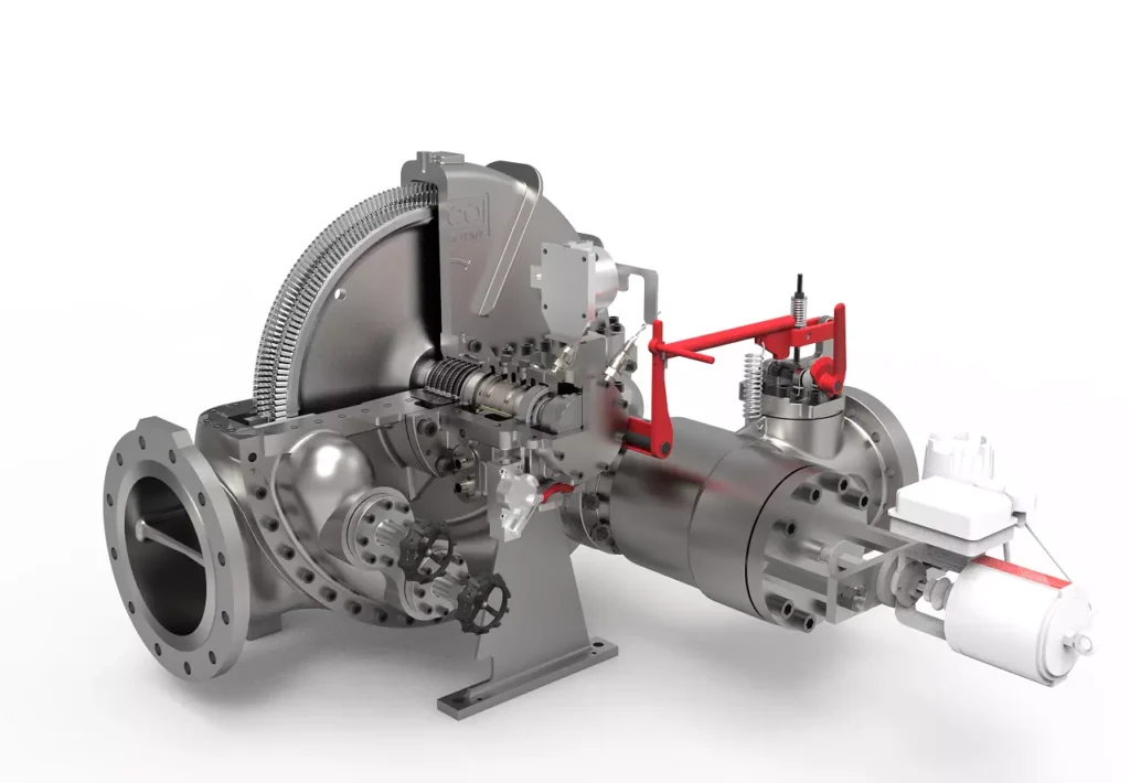
We design, manufacture and assembly Power Machines such as – diesel generators, electric motors, vibration motors, pumps, steam engines and steam turbines
EMS Power Machines is a global power engineering company, one of the five world leaders in the industry in terms of installed equipment. The companies included in the company have been operating in the energy market for more than 60 years.
EMS Power Machines manufactures steam turbines, gas turbines, hydroelectric turbines, generators, and other power equipment for thermal, nuclear, and hydroelectric power plants, as well as for various industries, transport, and marine energy.
EMS Power Machines is a major player in the global power industry, and its equipment is used in power plants all over the world. The company has a strong track record of innovation, and it is constantly developing new and improved technologies.
Here are some examples of Power Machines’ products and services:
- Steam turbines for thermal and nuclear power plants
- Gas turbines for combined cycle power plants and industrial applications
- Hydroelectric turbines for hydroelectric power plants
- Generators for all types of power plants
- Boilers for thermal power plants
- Condensers for thermal power plants
- Reheaters for thermal power plants
- Air preheaters for thermal power plants
- Feedwater pumps for thermal power plants
- Control systems for power plants
- Maintenance and repair services for power plants
EMS Power Machines is committed to providing its customers with high-quality products and services. The company has a strong reputation for reliability and innovation. Power Machines is a leading provider of power equipment and services, and it plays a vital role in the global power industry.
EMS Power Machines, which began in 1961 as a small factory of electric motors, has become a leading global supplier of electronic products for different segments. The search for excellence has resulted in the diversification of the business, adding to the electric motors products which provide from power generation to more efficient means of use.