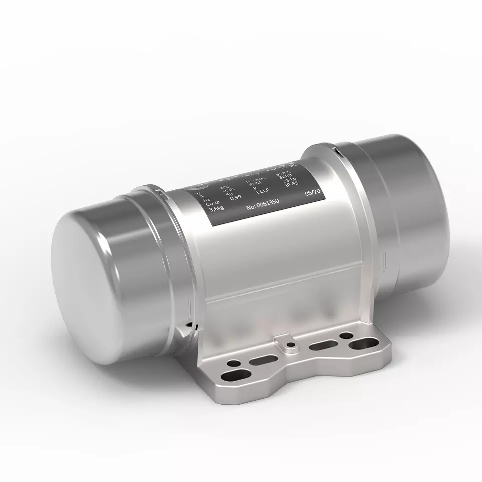
As an ATEX (Explosion Proof) Vibration Motor Manufacturer, we design and manufacture ATEX Vibration Motor for the industry. Small and Big sizes are available
The ATEX vibrator has been built in compliance with what was envisioned by the regulations in force prescribed by the European Community, and in particular with:
- Insulation class F;
- Tropicalized winding;
- IP66 mechanical protection (EN 60529), IK08 shock-resistance
level (EN 50102); - Admitted environmental temperature to ensure the indicated performance -20° C ÷ +40° C;
- Electrical construction according to Regulation EN 60034-1;
- Airborne noise measured in free field ≤ 70 dB (A) sec. IEC.
The ATEX vibrators listed in this booklet have been designed and built for specific needs and relative to use on vibrating machines. This ATEX vibrator, cannot be commissioned before the machine into which it will be incorporated has been declared in compliance with the dispositions in the 2006/46/EC Directive and successive amendments.
Instructions for Atex Vibration Motor

The ATEX motors presented in this catalog comply with the national and/ or international standards governing the construction of this type of equipment. EC type-examination certificates are drawn up by notified bodies, in accordance with ATEX Directive 94/9/ EC.
Certificates granted by the bodies listed opposite are recognized by all EC
countries. Approved equipment is authorized to carry the CE mark or the distinctive community mark
A zone with a risk of explosion is any place where an explosive or potentially explosive atmosphere may be present, the explosion risk being permanent, intermittent, or accidental. An explosive atmosphere is an atmosphere containing a mixture of air and inflammable substances (in the form of gas, vapor, fog, or combustible dust) which exists permanently. A potentially explosive atmosphere is one which may become explosive due to particular local or accident-related conditions.
In zones at risk of explosion, electrical installations must be reduced to what is essential to the operating needs. Two European Directives govern equipment and protection of workers occupying its zones.
Directive 94/9/EC: This Directive harmonizes the essential safety requirements with which equipment and protection systems,
intended for use in potentially explosive atmospheres, must comply in order to allow the free movement of goods and equipment inside the European Community
ATEX Electric Vibration Motor
ATEX Electric motor vibrators are excluded from the scope of Directive 2006/42/EC due to what is mentioned in art.1, par.2, point k. Its use for jobs different from those envisioned and non-conform to that described in this booklet, as well as being considered improper and prohibited, releases the Manufacturer from any direct and/or indirect liability.
The vibrator must however be fixed to a perfectly flat surface (Fig. 9,
page 8) using bolts (quality 8.8 – DIN 931-933) and nuts (quality 8.8 DIN 934) which are able to support high coupling torques (Fig. 10, page 8). Use a dynamometric wrench (Fig. 10, page 8) adjusted according to that stated in the “Coupling torque” table on page 106.
The diameter of the bolt, on the basis of the type of vibrator to install, must correspond to that indicated in the table on page 87. It is also indispensable to control that the bolts are tightened fully home. This control is particularly necessary during the initial functioning period.
Vibration Force Adjustment of an ATEX Vibration Motor
To adjust vibration intensity it is necessary to remove the weight
covers.
- It is usually necessary to adjust the weights in the same direction
on the two ends (Fig. 30, page 10). To allow exact adjustment of
the weights, the vibrators are equipped with a patented system
that prevents the adjustable weight to turn in the wrong direction
(Fig. 31, page 10). - Unscrew the mobile-weight screw fastener or nut (Fig. 32, page 10).
The adjustable weights positioned at the two ends of the shaft must
be positioned in a way to read the same value on the reference
percentage scale. The weights positioned at the two sides of the
vibrator can only be adjusted on two different values for particular
machines and for special uses. - For the X series adjustments must be carried out as for the corresponding X series motors.
- Once the eccentric weight has been taken to the desired value
tighten the screw fastener or nut using the dynamometric wrench
(Fig. 33, page 10) and repeat the same operation on the opposite
weight (see the table on page 105 for coupling torques
An ATEX vibration motor is a type of electric motor that is certified for use in hazardous areas where there is a risk of explosion. ATEX stands for “Atmosphere Explosive” and is a European directive that sets standards for the design, manufacturing, and installation of equipment that is intended for use in potentially explosive atmospheres.
ATEX vibration motors are typically used in applications where vibration is required to move or process materials, such as:
- Conveying materials: ATEX vibration motors can be used to convey materials such as powders, grains, and liquids through pipes, chutes, and hoppers.
- Screening and sieving: ATEX vibration motors can be used to screen and sieve materials to separate them by size or other properties.
- Compacting and settling: ATEX vibration motors can be used to compact and settle materials, such as concrete and powders, to ensure a uniform density.
- Mixing and blending: ATEX vibration motors can be used to mix and blend materials, such as chemicals and pharmaceuticals, to achieve a uniform mixture.
- Cleaning and descaling: ATEX vibration motors can be used to clean and descale surfaces, such as pipes and tanks, to remove debris and buildup.
ATEX vibration motors are designed to be safe for use in hazardous areas by:
- Encapsulated design: The motor is enclosed in a non-sparking and explosion-proof housing to prevent the ignition of flammable gases or vapors.
- Flameproof bearings: The motor bearings are sealed with flameproof seals to prevent the passage of flames or hot gases into the motor.
- Intrinsically safe electrical connections: The motor’s electrical connections are intrinsically safe, meaning that they cannot generate sparks or heat that could ignite flammable gases or vapors.
ATEX vibration motors are a valuable tool for a wide range of applications in hazardous areas. They can help to improve safety, efficiency, and productivity in these environments.
Here are some examples of ATEX vibration motors in use:
- ATEX vibration motors are used in mining and drilling operations to vibrate screens and conveyors to separate materials and transport them through the mining process.
- ATEX vibration motors are used in the food and beverage industry to vibrate sieves to screen powders and grains, and to vibrate mixers to blend ingredients.
- ATEX vibration motors are used in the chemical and pharmaceutical industries to vibrate reactors and mixers to ensure uniform mixing of chemicals and pharmaceuticals.
- ATEX vibration motors are used in the oil and gas industry to vibrate tanks and pipes to remove debris and buildup, and to vibrate filters to remove impurities from fluids.
- ATEX vibration motors are used in the power generation industry to vibrate screens and conveyors to transport coal and other fuels, and to vibrate ash collectors to remove ash from exhaust gases.
Conveying materials with ATEX Vibration Motor
Conveying materials is the process of moving materials from one location to another. There are many different methods of conveying materials, each with its own advantages and disadvantages. The most appropriate method for a particular application will depend on the type of material being conveyed, the distance it needs to be moved, and the desired rate of conveyance.
Common methods of conveying materials include:
- Conveyor belts: Conveyor belts are a common method of conveying a wide variety of materials over a relatively short distance. They are typically used in industries such as mining, manufacturing, and food processing.
- Screw conveyors: Screw conveyors are used to convey materials in a trough or tube. They are typically used for conveying bulk materials such as grain, sand, and gravel.
- Pneumatic conveyors: Pneumatic conveyors use air pressure to move materials through a pipe. They are typically used for conveying dry materials such as powders and grains.
- Hydraulic conveyors: Hydraulic conveyors use water to move materials through a pipe. They are typically used for conveying slurries, such as cement and concrete.
- Bucket elevators: Bucket elevators are used to convey materials vertically. They are typically used in industries such as mining and grain processing.
- Vibratory feeders: Vibratory feeders use vibration to move materials from a hopper to a conveyor belt or other conveyance system. They are typically used in industries such as mining and manufacturing.
Factors to consider when choosing a method of conveying materials include:
- The type of material being conveyed: The material’s properties, such as its size, shape, and abrasiveness, will affect the type of conveyor that can be used.
- The distance the material needs to be moved: The distance the material needs to be moved will affect the type of conveyor that is most efficient.
- The desired rate of conveyance: The desired rate of conveyance will affect the size and capacity of the conveyor.
- The available space: The available space will affect the type of conveyor that can be used.
- The budget: The budget will affect the type of conveyor that can be purchased.
- The environmental impact: The environmental impact of the conveyor should be considered, such as its energy consumption and noise pollution.
Screw conveyors with an ATEX Vibration Motor
Screw conveyors, also known as auger conveyors, are a type of material handling equipment that uses a helical screw blade, called a “flighting,” to move liquid or granular materials. They are used in many bulk handling industries to transport materials from one point to another.
How Screw Conveyors Work
Screw conveyors consist of a trough or tube that contains a rotating helical screw. As the screw rotates, it moves the material along the trough or tube. The screw’s design and pitch, which is the distance between the threads of the screw, can be adjusted to match the specific material being conveyed.
Types of Screw Conveyors
There are several types of screw conveyors, each with its own specific applications. Some common types of screw conveyors include:
- Horizontal screw conveyors: These are the most common type of screw conveyor and are used to transport materials over a horizontal or slightly inclined plane.
- Vertical screw conveyors: These are used to transport materials vertically.
- Inclined screw conveyors: These are used to transport materials at an incline.
- Tubular screw conveyors: These are enclosed in a tube, which prevents material from spilling out.
- Trough screw conveyors: These are open-topped and are used for materials that do not need to be protected from the environment.
Advantages of Screw Conveyors
Screw conveyors offer a number of advantages over other types of material handling equipment, including:
- Simplicity: Screw conveyors are relatively simple machines and require minimal maintenance.
- Versatility: Screw conveyors can be used to transport a wide variety of materials, including liquids, solids, and powders.
- Efficiency: Screw conveyors are very efficient and can transport materials over long distances with minimal energy consumption.
- Reliability: Screw conveyors are very reliable and can operate in a variety of environments.
- Cost-effective: Screw conveyors are relatively inexpensive to purchase and operate.
Disadvantages of Screw Conveyors
Screw conveyors also have a few disadvantages, including:
- Limited capacity: Screw conveyors have a limited capacity and are not well-suited for transporting large quantities of materials.
- Material damage: Screw conveyors can damage some materials, such as delicate or friable materials.
- Not suitable for long distances: Screw conveyors are not well-suited for transporting materials over very long distances.
Applications of Screw Conveyors
Screw conveyors are used in a wide variety of industries, including:
- Agriculture: Screw conveyors are used to transport grain, feed, and other agricultural products.
- Mining: Screw conveyors are used to transport ore, coal, and other mining materials.
- Food processing: Screw conveyors are used to transport food ingredients, such as flour, sugar, and spices.
- Chemical processing: Screw conveyors are used to transport chemicals, powders, and other materials.
- Waste management: Screw conveyors are used to transport waste materials, such as sewage sludge and solid waste.
Overall, screw conveyors are a versatile and reliable type of material handling equipment that is used in a wide variety of industries. They are a cost-effective and efficient way to transport a wide variety of materials.
Pneumatic conveyors with an ATEX Vibration Motor
Pneumatic conveyors are systems that use air pressure to transport bulk materials, such as powders, granules, and pellets, through pipes or tubes. They are a versatile and efficient way to move materials over long distances and in complex configurations.
How Pneumatic Conveyors Work
Pneumatic conveyors consist of three main components:
- A blower or compressor: This provides the air pressure that is used to move the material.
- A feed hopper or inlet: This is where the material is introduced into the system.
- A discharge hopper or outlet: This is where the material is released from the system.
The material is moved through the system by a stream of air that is created by the blower or compressor. The air pressure forces the material through the pipes or tubes, and the velocity of the air stream prevents the material from settling out.
Types of Pneumatic Conveyors
There are two main types of pneumatic conveyors:
- Dilute phase conveyors: These conveyors use a high volume of air to move a relatively small amount of material. The material is suspended in the air stream and is transported in a turbulent flow.
- Dense phase conveyors: These conveyors use a lower volume of air to move a larger amount of material. The material is fluidized and is transported in a plug flow.
Advantages of Pneumatic Conveyors
Pneumatic conveyors offer a number of advantages over other types of material handling equipment, including:
- Versatility: Pneumatic conveyors can be used to transport a wide variety of materials, including powders, granules, pellets, and even liquids.
- Efficiency: Pneumatic conveyors are very efficient and can transport materials over long distances with minimal energy consumption.
- Cleanliness: Pneumatic conveyors are a clean and dust-free way to transport materials.
- Gentleness: Pneumatic conveyors are gentle on materials and will not damage delicate or friable materials.
- Adaptability: Pneumatic conveyors can be adapted to a wide variety of configurations, including bends, inclines, and declines.
Disadvantages of Pneumatic Conveyors
Pneumatic conveyors also have a few disadvantages, including:
- High initial cost: Pneumatic conveyors can be expensive to purchase and install.
- Maintenance: Pneumatic conveyors require regular maintenance to ensure optimal performance.
- Noise: Pneumatic conveyors can be noisy, especially those that use high-pressure air.
- Not suitable for certain materials: Pneumatic conveyors are not well-suited for transporting materials that are heavy, wet, or sticky.
Applications of Pneumatic Conveyors
Pneumatic conveyors are used in a wide variety of industries, including:
- Food processing: Pneumatic conveyors are used to transport food ingredients, such as flour, sugar, and spices.
- Chemical processing: Pneumatic conveyors are used to transport chemicals, powders, and other materials.
- Pharmaceutical manufacturing: Pneumatic conveyors are used to transport active pharmaceutical ingredients (APIs) and other sensitive materials.
- Plastics manufacturing: Pneumatic conveyors are used to transport plastic pellets and powders.
- Grain handling: Pneumatic conveyors are used to transport grain, feed, and other agricultural products.
Overall, pneumatic conveyors are a versatile and efficient way to transport bulk materials. They are a good choice for applications that require clean, gentle, and dust-free material handling.
Hydraulic conveyors with an ATEX Vibration Motor
Hydraulic conveyors, also known as slurry conveyors, are a type of material handling equipment that uses pressurized fluid to transport materials through pipes or tubes. They are a versatile and efficient way to move materials over long distances, in complex configurations, and in elevated or underground applications.
How Hydraulic Conveyors Work
Hydraulic conveyors consist of three main components:
- A pump: This provides the pressurized fluid that is used to move the material.
- A feed hopper or inlet: This is where the material is introduced into the system.
- A discharge hopper or outlet: This is where the material is released from the system.
The material is mixed with a fluid, typically water or a slurry, and the pressurized fluid forces the mixture through the pipes or tubes. The velocity of the fluid stream prevents the material from settling out.
Types of Hydraulic Conveyors
There are two main types of hydraulic conveyors:
- Pressurized water conveyors: These conveyors use water as the pressurized fluid. They are commonly used to transport materials with a low settling velocity, such as sand, gravel, and coal.
- Slurry conveyors: These conveyors use a slurry, which is a mixture of water and solids, as the pressurized fluid. They are commonly used to transport materials with a high settling velocity, such as ores, tailings, and drilling fluids.
Advantages of Hydraulic Conveyors
Hydraulic conveyors offer a number of advantages over other types of material handling equipment, including:
- Versatility: Hydraulic conveyors can be used to transport a wide variety of materials, including solids, liquids, and slurries.
- Efficiency: Hydraulic conveyors are very efficient and can transport materials over long distances with minimal energy consumption.
- Abrasion resistance: Hydraulic conveyors are resistant to abrasion, making them a good choice for transporting abrasive materials.
- Adaptability: Hydraulic conveyors can be adapted to a wide variety of configurations, including bends, inclines, and declines.
- Low maintenance: Hydraulic conveyors require relatively low maintenance compared to other types of conveyors.
Disadvantages of Hydraulic Conveyors
Hydraulic conveyors also have a few disadvantages, including:
- High initial cost: Hydraulic conveyors can be expensive to purchase and install.
- Water consumption: Hydraulic conveyors consume a significant amount of water, which can be a concern in areas with limited water resources.
- Pump maintenance: The pump is a critical component of a hydraulic conveyor and requires regular maintenance to ensure optimal performance.
- Not suitable for certain materials: Hydraulic conveyors are not well-suited for transporting materials that are light and fluffy, such as powders and dusts.
Applications of Hydraulic Conveyors
Hydraulic conveyors are used in a wide variety of industries, including:
- Mining: Hydraulic conveyors are used to transport ore, tailings, and other mining materials.
- Construction: Hydraulic conveyors are used to transport concrete, grout, and other construction materials.
- Power generation: Hydraulic conveyors are used to transport coal, ash, and other materials in power plants.
- Dredging: Hydraulic conveyors are used to transport sand, gravel, and other materials from the bottom of bodies of water.
- Wastewater treatment: Hydraulic conveyors are used to transport sewage sludge and other waste materials.
Overall, hydraulic conveyors are a versatile and efficient way to transport materials, particularly for applications that require long-distance transport, complex configurations, and high-volume material handling.
Bucket elevators with an ATEX Vibration Motor
Bucket elevators are a type of material handling equipment that uses a series of buckets to transport materials vertically. They are commonly used in industries such as mining, grain processing, and food manufacturing.
How Bucket Elevators Work
Bucket elevators consist of four main components:
- A boot: This is the bottom of the elevator and contains the drive mechanism.
- A leg: This is the vertical section of the elevator that houses the buckets.
- A head: This is the top of the elevator and contains the discharge mechanism.
- A bucket chain: This is an endless chain that carries the buckets.
The buckets are attached to the bucket chain, and as the chain rotates, the buckets scoop up material from the boot and carry it to the head. At the head, the buckets are emptied, and the material is discharged into a hopper or conveyor.
Types of Bucket Elevators
There are two main types of bucket elevators:
- Centrifugal discharge elevators: These elevators use centrifugal force to empty the buckets at the head. They are typically used for transporting materials that are not easily damaged, such as grain and minerals.
- Positive discharge elevators: These elevators use a mechanical mechanism to empty the buckets at the head. They are typically used for transporting materials that are easily damaged, such as food products and chemicals.
Advantages of Bucket Elevators
Bucket elevators offer a number of advantages over other types of material handling equipment, including:
- Versatility: Bucket elevators can be used to transport a wide variety of materials, including solids, liquids, and slurries.
- Reliability: Bucket elevators are very reliable and can operate in a variety of environments.
- Efficiency: Bucket elevators are very efficient and can transport materials over a long distance with minimal energy consumption.
- Low maintenance: Bucket elevators require relatively low maintenance compared to other types of elevators.
- Cost-effective: Bucket elevators are relatively inexpensive to purchase and operate.
Disadvantages of Bucket Elevators
Bucket elevators also have a few disadvantages, including:
- Limited capacity: Bucket elevators have a limited capacity and are not well-suited for transporting large quantities of materials.
- Material damage: Bucket elevators can damage some materials, such as delicate or friable materials.
- Not suitable for long distances: Bucket elevators are not well-suited for transporting materials over very long distances.
- Noise: Bucket elevators can be noisy, especially those that use centrifugal discharge.
Applications of Bucket Elevators
Bucket elevators are used in a wide variety of industries, including:
- Mining: Bucket elevators are used to transport ore, coal, and other mining materials.
- Grain processing: Bucket elevators are used to transport grain, feed, and other agricultural products.
- Food manufacturing: Bucket elevators are used to transport food ingredients, such as flour, sugar, and spices.
- Chemical processing: Bucket elevators are used to transport chemicals, powders, and other materials.
- Waste management: Bucket elevators are used to transport waste materials, such as sewage sludge and solid waste.
Overall, bucket elevators are a versatile, reliable, and efficient way to transport materials vertically. They are a good choice for applications that require low maintenance and cost-effective material handling.
Vibratory feeders with an ATEX Vibration Motor
Vibratory feeders are a type of mechanical feeder that uses vibration to transport or feed bulk materials or components from one place to another. They are widely used in various industries, including manufacturing, mining, agriculture, pharmaceuticals, and food processing. Here are some key aspects of vibratory feeders:
- Operating Principle:
- Vibratory feeders use the principle of vibrations to move materials through a trough or tube.
- An electromagnetic drive or a mechanical drive generates vibrations that move the material along the trough.
- The vibration frequency and amplitude can be adjusted to control the flow rate and ensure proper feeding.
- Components:
- Drive Unit: This is the power source that generates the vibrations. It can be an electromagnetic coil or a set of mechanical motors with eccentric weights.
- Trough or Tube: The material is transported through a trough or tube, which is often customized to suit the specific application.
- Springs or Rubber Mounts: These components help isolate the vibration to the trough or tube, preventing excessive vibration transfer to the supporting structure.
- Applications:
- Vibratory feeders are used in a variety of applications, such as conveying bulk materials, feeding components to automated assembly lines, sorting, and aligning parts for processing.
- They are suitable for handling a wide range of materials, including powders, granules, and large, irregularly shaped objects.
- Advantages:
- Precise Control: Vibratory feeders offer precise control over the flow rate of materials, making them suitable for applications that require accurate dosing.
- Efficiency: They are energy-efficient and require minimal maintenance compared to other types of feeders.
- Customization: Vibratory feeders can be customized to handle specific materials and meet the requirements of different industries.
- Challenges:
- Wear and Tear: Continuous vibration can lead to wear and tear on the components over time.
- Material Flow Issues: Some materials may have characteristics that make it challenging to maintain a consistent flow.
- Types of Vibratory Feeders:
- Bowl Feeders: Circular-shaped bowls with spiral tracks inside for orienting and feeding components.
- Linear Feeders: Straight-line configurations for transporting materials in a linear direction.
- Hopper Feeders: Used for bulk material handling and storage, often with a vibrating bottom to facilitate flow.
Vibratory feeders play a crucial role in the automation and efficiency of various industrial processes by ensuring a controlled and reliable flow of materials.
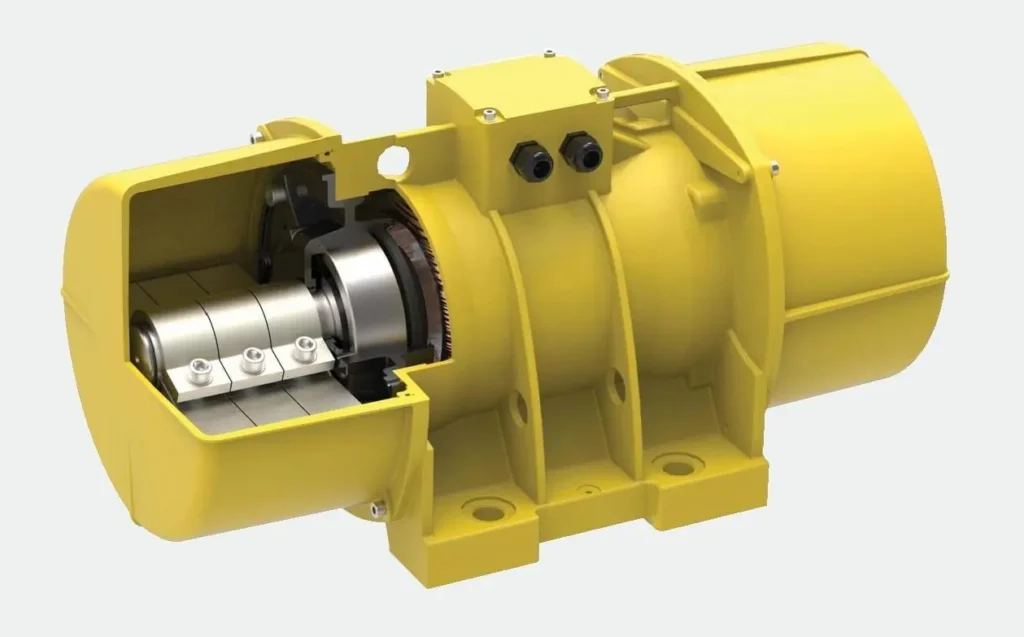
Vibration motors are compact electric motors that generate vibrations or oscillations when energized. They are commonly used in a variety of applications where controlled vibration is required. Here’s an overview of vibration motors:
Components and Types:
- Rotor:
- The rotor is the rotating component of the motor that, when energized, causes the motor to vibrate.
- Stator:
- The stator is the stationary part of the motor that surrounds the rotor and provides the magnetic field necessary for the motor to operate.
- Eccentric Weight (Vibrator):
- Many vibration motors have an eccentric weight attached to the rotor. The eccentric weight’s off-center rotation creates an imbalance, leading to vibrations.
Rotor of the Vibration Motor
The rotor is a crucial component in various rotating machinery, such as electric motors, generators, turbines, and pumps. Its function and design can vary depending on the type of machinery it is part of. Here, I’ll provide a general overview of the rotor’s role in the context of electric motors, as this seems to be the most relevant to your previous inquiries.
Rotor in Electric Motors:
In the context of electric motors, the rotor is the rotating part of the motor that interacts with the stator, generating mechanical motion. There are two primary types of rotors in electric motors: squirrel-cage rotors and wound rotors.
- Squirrel-Cage Rotor:
- The squirrel-cage rotor is the most common type used in induction motors. It consists of laminated iron cores stacked together, and the conductors are typically aluminum or copper bars placed in slots on the iron cores. The ends of the conductors are shorted together by end rings, forming a closed loop.
- When electric current flows through the stator windings, it creates a rotating magnetic field. This magnetic field induces a current in the rotor conductors due to electromagnetic induction. The interaction between the stator’s magnetic field and the rotor’s induced current produces torque, causing the rotor to turn and drive the mechanical load.
- Wound Rotor:
- The wound rotor, also known as a slip ring rotor, has a set of insulated coils or windings connected to slip rings on the rotor shaft. The slip rings allow external electrical connections to the rotor windings.
- In operation, the wound rotor allows for external resistance to be connected to the rotor windings, enabling control of the motor’s speed and torque characteristics. This type of rotor is often used in applications where precise control over the motor’s performance is required.
Key Characteristics:
- Material:
- Rotor cores are typically made of laminated sheets of magnetic material (such as iron or steel) to reduce eddy current losses.
- Construction:
- The rotor construction can vary based on the motor type. In squirrel-cage rotors, conductive bars are embedded in the core, while wound rotors have coils or windings.
- Rotation:
- The rotor rotates within the stator’s magnetic field, creating mechanical motion. The rotational speed is influenced by the frequency and amplitude of the electric current in the stator.
- Torque Production:
- The primary function of the rotor is to generate torque by interacting with the stator’s magnetic field. This torque is responsible for driving the mechanical load connected to the motor.
- Control (Wound Rotor):
- In wound rotor motors, the external connections to the slip rings allow for additional control over the motor’s performance, including speed and torque regulation.
Applications:
Rotors are found in various types of electric motors used in a wide range of applications, including:
- Induction Motors: Squirrel-cage rotors are commonly used in induction motors for applications like pumps, fans, and compressors.
- Synchronous Motors: Rotors in synchronous motors maintain synchrony with the stator’s rotating magnetic field, making them suitable for applications where precise speed control is required.
- Wound Rotor Motors: These are used in applications requiring adjustable speed and torque characteristics, such as in large industrial drives.
Understanding the characteristics and types of rotors is essential in designing electric motors for specific applications, tailoring their performance to meet the requirements of different industries.
Stator of the ATEX Vibration Motor
The stator is a key component in electric motors, generators, and other rotating machinery. It serves as the stationary part of the machine, providing a magnetic field that interacts with the rotor to generate motion or electricity. Here, I’ll provide an overview of the stator in the context of electric motors:
Role of the Stator in Electric Motors:
- Magnetic Field Generation:
- The primary function of the stator is to generate a magnetic field when electric current flows through its windings. This magnetic field is essential for the operation of the motor.
- Interaction with the Rotor:
- The stator’s magnetic field interacts with the rotor (the rotating part of the motor), creating a force that produces mechanical motion. This motion is harnessed to drive various applications, such as turning a fan, pumping water, or propelling a vehicle.
- Stator Windings:
- The stator typically consists of a core made of laminated iron sheets to reduce eddy current losses. The stator windings, usually made of copper or aluminum, are wound around the core. The arrangement of these windings determines the motor’s characteristics.
Key Components and Characteristics:
- Laminated Core:
- The stator core is often made up of laminated sheets of magnetic material (such as iron or steel) to minimize energy losses due to eddy currents.
- Stator Windings:
- Copper or aluminum conductors are wound around the stator core to form coils. The configuration and connection of these windings influence the motor’s performance.
- Number of Poles:
- The number of poles in the stator refers to the number of magnetic poles created by the stator windings. The pole configuration affects the motor’s speed and torque characteristics.
- Three-Phase System:
- In many industrial applications, especially in larger motors, the stator windings are configured as a three-phase system. Three-phase motors are common due to their efficiency and smoother operation.
Types of Stators:
- Squirrel-Cage Stator:
- In squirrel-cage induction motors, the stator windings create a rotating magnetic field. The interaction between this field and the rotor’s conductive bars induces currents in the rotor, producing torque.
- Wound Stator:
- Some motors, especially those designed for specific control applications, have wound stators. These motors allow for external control over the stator windings, influencing the motor’s speed and torque characteristics.
Applications
Stators are integral to a wide range of electric motor applications, including:
- Induction Motors: In squirrel-cage induction motors, the stator’s rotating magnetic field induces currents in the rotor, generating torque for applications such as fans, pumps, and compressors.
- Synchronous Motors: Stators in synchronous motors maintain synchrony with the power supply frequency, making them suitable for applications requiring precise speed control.
- Wound Rotor Motors: Motors with wound stators provide additional control over speed and torque, making them suitable for industrial processes that require adjustable motor performance.
- Three-Phase Motors: Stators configured as three-phase systems are prevalent in industrial and commercial applications due to their efficiency and balanced power distribution.
The design and configuration of the stator are critical factors in determining the performance characteristics of an electric motor. Engineers carefully consider these factors to tailor motors for specific applications, ensuring optimal efficiency and functionality.
Eccentric Weight (Vibrator) of an ATEX Vibration Motor
The eccentric weight, also known as a vibrator or unbalance weight, is a crucial component in vibration motors. It plays a key role in generating vibrations by introducing an imbalance in the motor’s rotational movement. Here’s how the eccentric weight functions in a vibration motor:
Function and Operation
- Imbalance Creation:
- The eccentric weight is intentionally placed off-center on the motor’s rotating shaft. This off-center positioning creates an imbalance in the motor’s rotation.
- Centrifugal Force:
- As the motor rotates, the eccentric weight generates a centrifugal force due to its off-center position. This force creates an imbalance in the distribution of mass, leading to vibrations.
- Vibration Generation:
- The imbalance induced by the eccentric weight causes the motor to vibrate as it rotates. These vibrations are then transferred to the device or surface to which the motor is attached.
- Adjustment for Desired Vibrations:
- The size and position of the eccentric weight can be adjusted to control the amplitude and frequency of the vibrations produced by the motor. This allows for customization based on the specific requirements of the application.
Applications
Vibration motors with eccentric weights are commonly used in various applications where controlled vibrations are desired. Some common applications include:
- Haptic Feedback in Devices:
- Vibration motors with eccentric weights are frequently used in smartphones, tablets, and other electronic devices to provide haptic feedback during touch interactions or notifications.
- Gaming Controllers:
- Gaming controllers often incorporate vibration motors to enhance the gaming experience by providing tactile feedback during specific in-game events.
- Wearable Devices:
- Smartwatches and fitness trackers may use vibration motors with eccentric weights to deliver notifications and alerts to the wearer.
- Industrial Equipment:
- Vibration motors are used in industrial equipment for tasks such as compacting soil, conveying materials, and facilitating sieving processes.
- Medical Devices:
- Some medical devices use vibration motors for various applications, including alerting users or providing feedback.
- Automotive Applications:
- Vibration motors can be found in automobiles for haptic feedback in infotainment systems, alerting drivers, and enhancing the user experience.
- Consumer Electronics:
- Beyond smartphones, vibration motors with eccentric weights find applications in a range of consumer electronics, such as handheld gaming devices and remote controls.
Considerations
- Amplitude and Frequency:
- The amplitude (intensity) and frequency (speed) of vibrations produced by the motor depend on factors such as the size and positioning of the eccentric weight.
- Power Consumption:
- The power consumption of a vibration motor is an important consideration, especially in battery-powered devices.
- Durability and Lifespan:
- The durability and lifespan of the motor, including the eccentric weight, are crucial, especially in applications where the motor is subjected to frequent use.
- Control Options:
- Some vibration motors with eccentric weights come with control options to adjust vibration patterns or synchronize with specific events.
The eccentric weight is a design feature that allows vibration motors to efficiently generate controlled vibrations, making them versatile components in a variety of applications. The selection of a vibration motor with the appropriate eccentric weight characteristics depends on the specific requirements of the application.
Operating Principle
- Rotational Movement:
- When the motor is powered, the rotor (sometimes with an eccentric weight) starts to rotate.
- Centrifugal Force:
- The eccentricity in the rotor’s rotation creates a centrifugal force, leading to an imbalance in the system.
- Vibration Generation:
- The imbalance causes the motor to vibrate, producing oscillations that can be felt externally.
Types of Vibration Motors:
- Coin or Flat Motors:
- These motors are small, flat, and coin-shaped. They are commonly used in mobile phones, pagers, and other portable electronic devices.
- Cylinder Motors:
- These motors have a cylindrical shape and are often used in applications where a more extended vibration pattern is required.
- Pancake Motors:
- Pancake motors are thin and flat, similar to coin motors but with a larger diameter. They are suitable for applications requiring a larger vibrating surface.
- Brushed Motors:
- Traditional brushed DC motors can be used as vibration motors by attaching an eccentric weight. However, specialized vibration motors are more common for this purpose.
- Brushless Motors:
- Brushless vibration motors use electronic commutation and are known for their reliability and longer lifespan compared to brushed motors.
Applications:
- Haptic Feedback in Devices:
- Vibration motors are commonly used in smartphones, tablets, and other electronic devices to provide haptic feedback, such as during touchscreen interactions.
- Gaming Controllers:
- Vibration motors enhance the gaming experience by providing tactile feedback during specific in-game events.
- Wearable Devices:
- Smartwatches and fitness trackers often incorporate vibration motors to deliver notifications and alerts to the wearer.
- Industrial Equipment:
- Vibration motors are used in industrial equipment for tasks such as compacting soil, conveying materials, and facilitating sieving processes.
- Medical Devices:
- Some medical devices use vibration motors for various applications, including alerting users or providing feedback.
- Automotive Applications:
- Vibration motors are used in automobiles for haptic feedback in infotainment systems, alerting drivers, and enhancing the user experience.
- Consumer Electronics:
- Beyond smartphones, vibration motors find applications in a range of consumer electronics, such as handheld gaming devices and remote controls.
- Vibrating Conveyors:
- In industrial settings, vibration motors are employed in vibrating conveyors for material handling.
- Alert Systems:
- Vibration motors are used in alert systems, such as in alarms and pagers, where silent notifications are required.
Considerations:
- Amplitude and Frequency:
- The amplitude (intensity) and frequency (speed) of vibrations generated by the motor can be crucial, depending on the application.
- Power Consumption:
- The power consumption of a vibration motor is an important consideration, especially in battery-powered devices.
- Durability and Lifespan:
- The durability and lifespan of the motor are crucial, especially in applications where the motor is subjected to frequent use.
- Control Options:
- Some vibration motors come with control options to adjust vibration patterns or synchronize with specific events.
Vibration motors are versatile components used in a wide range of applications to provide tactile feedback, alert users, or facilitate various mechanical processes. The selection of a vibration motor depends on the specific requirements of the application.
Vibration motors are compact electric motors used to generate vibrations in a wide range of industrial and commercial applications. These motors consist of a rotor with an eccentric weight attached to it. When the motor rotates, the weight generates a centrifugal force, causing the motor to vibrate. Vibration motors are used to create various types of vibrations, such as linear vibrations, circular vibrations, and elliptical vibrations.
Vibration motors are commonly used in mobile phones, pagers, and other portable electronic devices to provide haptic feedback. They are also used in various industrial applications, such as conveyor systems, packaging equipment, and vibrating tables. In addition, they are used in automotive applications, such as airbag systems, seatbelt tensioners, and engine mounts.
Vibration motors come in different sizes and configurations, depending on the application requirements. They can be classified based on their operating principle, such as electromagnetic, eccentric rotating mass (ERM), and linear resonant actuator (LRA) motors.
Electromagnetic Vibration Motors
Electromagnetic vibration motors are the most common type of vibration motors. They consist of a coil of wire and a permanent magnet. When an electric current is passed through the coil, it generates a magnetic field that interacts with the magnetic field of the permanent magnet, causing the motor to vibrate.
ERM vibration motors consist of an eccentric rotating mass attached to the motor shaft. When the motor rotates, the eccentric mass generates a centrifugal force that causes the motor to vibrate.
LRA vibration motors use a similar principle to ERM motors but are more precise and consume less power. They consist of a moving mass attached to a spring. When an electric current is passed through the motor, the mass moves back and forth, generating vibrations.
Overall, vibration motors are versatile devices that play an essential role in many industrial and commercial applications. They provide a simple and effective way to create controlled vibrations that can be used for a wide range of purposes.
Types of ATEX Vibration Motor
What is a vibration motor? A vibration motor is a compact size coreless DC or AC motor used to inform the users of receiving the signal by vibrating, with no sound. Vibration motors are widely used in a variety of applications including cell phones, handsets, pagers, and so on.
The main feature of vibration motors is the magnet coreless AC or DC motors are permanent, which means they will always have their magnetic properties (unlike an electromagnet, which only behaves like a magnet when an electric current runs through it); another main feature is the size of the motor itself is small, and thus lightweight.
Moreover, the noise and the power consumption that the motor produces while used are low. Based on those features, the performance of the motor is highly reliable. The vibration motors are configured in two basic varieties: coin (or flat) and cylinder (or bar). There are some components in both of their internal constructions.
EMS Power Machines vibration motors are intended and suited to drive vibrating devices, like e.g.: vibrating conveyor chutes, vibrating pipes, screen conveyors, screening machines, spiral conveyors, automatic sorting machines, knock-out grates, vibrating trestles, resonance conveyors, vibrating mills and fluid-bed dryers, bin vibrating machines, etc.
Any other use or application beyond the specified shall be deemed an application for purposes other than the intended.
No claims will be accepted by EMS Power Machines for any damage resulting therefrom. Application for the purpose intended shall also include compliance with the operating manual and, in particular, the inspection and maintenance regulations. For technical information on our motors, such as type, speed, working torque and centrifugal force, and electrical values please refer to the leaflet of vibration motors or the motor datasheet.
Construction of Vibration Motors
Rotor: The rotor is the non-stationary part of a rotary electric motor. The wires and magnetic field of the motor are arranged so that a torque is developed about the rotor’s axis. In some designs, the rotor can act to serve as the motor’s armature, across which the input voltage is supplied.
The stator is the stationary part of a rotary electric motor. It could be worked as the magnet field and interact with the armature to create motion. Another function of the stator is it could act as the armature, which receives its influence from moving field coils on the rotor.
A commutator is a rotary electrical switch in certain types of electric motors or electrical generators that periodically reverses the current direction between the rotor and the external circuit. In a motor, it applies power to the best location on the rotor, and in a generator, picks off power similarly. As a switch, it has an exceptionally long life, considering the number of circuit makes and breaks that occur in normal operation.
The armature in this motor is a set of thin metal plates stacked together, with thin copper wire coiled around each of the three poles of the armature. (How the electric motor works) The main function of the armature is to convert magnetic energy into kinetic energy.
The Windings
Windings consist of some turns of coils. These coils are assembled to generate a magnetic field once the electricity goes through them.
In order to make a vibrating alert, a weight mass needs to be attached to the shaft. Through the high-speed displacement of weight, vibration can be achieved. Moreover, the magnitude of the force can be controlled and adjusted, and the factors that could affect it will be discussed below.
In the motor’s shaft, the brushes conduct the current between the stator and coils. The life of the motor depends on when the brushes will be worn out. Based on this factor, a brushless dc motor, which is also called BLDC, is used to extend the life of motors.
The cylinder shape is also called a bar-type vibration motor. This vibrating motor is essentially a motor that is improperly balanced. In other words, there is an off-centered weight attached to the motor’s rotational shaft that produces a centrifugal force while rotating. This unbalanced force displaces the motor. Its high-speed displacement makes the motor wobble, which is known as “vibrating”.
The wobble can be changed by the weight mass you attach, the weight’s distance to the shaft, and the speed at which the motor spins. What’s more, the centrifugal force, which is generated by rotating an unbalanced weight, causes the motor vibrates in 2 axes (Z axis and X axis).
Besides, the centrifugal force can be calculated through the equations in figure 3. According to the relationship of each component in this equation, it is easy to tell that a larger weight mass with a bigger offset from the shaft will produce more force and hence more vibration amplitude. Moreover, increasing the voltage supplied to the motor will increase its speed, and therefore the vibration frequency, as well as the vibration amplitude.
Technical Characteristics of the ATEX Vibration Motor
Power Supply: The power supply of vibration motors is 230 ∆/400 Y Volt and 50-60 Hz as a standard. Please contact us for the special voltage and frequency rate.
Electric Motor: The electric motor vibration motors have higher starting torques than a three-phase asynchronous electric motor. The overheating problem of the vibration motor due to no ventilation system is taken into consideration at designing.
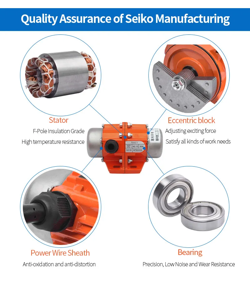
Polarity: As standard vibration, motors are manufactured in 2, 4, 6, and 8 poles. Motor Shaft: The motor shaft of vibration motors is produced from C45 structural steel. Rotor: Rotor is produced by injecting high alloyed aluminum into the channel of the packed siliceous sheet metal.
Bearings: The series with lower centrifugal force (from VA to VC series) are equipped with deep groove ball bearing (2Z) with C3 internal clearance. The series with higher centrifugal force (from VD to VL series) are equipped with cylindrical roller bearings ( NJ Series) with C4 internal clearance. All of the bearings, that we are using, are suitable to operate at heavy-duty conditions.
Eccentric Weights: The weights can adjust easily by rotating or subtracting according to the type of vibration motors. Casing: The casing of the vibration motor is high alloyed aluminum from the VA series to the VE series. The casing of vibration motors that have higher centrifugal force (from VE series to VL series) is nodular cast iron (GGG 50).
Eccentric Weights Cover: The eccentric weights cover is sheet metal up to the VK series. VK and VL series have aluminum weight covers. The purpose of the eccentric weight covers is to protect the eccentric weights from external factors and provide safety. Insulation Class: The insulation class of our standard range vibration motor is F class (155 °C).
Degree of Protection: The degree of protection is IP 66. Lubrication: Except for the vibration motors that used self-lubricated bearings (deep groove ball bearings – 2Z), the bearings of the vibration motors (NJ series) are lubricated in our factory. Apart from this, bearings have to be
lubricated with the aid of a grease nipple that is on the vibration motor case during maintenance. The required grease amount is written in the “ Vibration Motor User’s Manual”.
Painting: Vibration motors are painted with RAL 1003 paint by using the electrostatic painting method.
As a Vibration Equipment Manufacturer, we design and manufacture AC and DC vibration motors for the industry. Small and Big sizes are available
Vibration equipment is a special electric motor, on which both ends of unbalanced weights are fixed. These unbalanced weights cause vibration during rotation.
Vibration equipment refers to machines and devices designed to generate controlled vibrations for various purposes across different industries. These devices are used in applications such as materials testing, quality control, manufacturing, construction, and research. Here are some common types of vibration equipment:
- Vibration Tables:
- Purpose: Vibration tables are used to settle, compact, and evenly distribute materials. They find applications in packaging, foundry operations, concrete compaction, and more.
- Usage: Vibration tables are often used in product testing, quality control, and manufacturing processes to ensure uniformity and reduce voids in materials.
- Vibration Shakers (Electrodynamic Shakers):
- Purpose: Vibration shakers are used for dynamic testing of structures, components, and materials. They are commonly used in aerospace, automotive, and electronic industries for durability and fatigue testing.
- Usage: Vibration shakers are employed to simulate real-world vibrations and assess how materials and structures respond to dynamic loading.
- Vibration Testing Systems:
- Purpose: Comprehensive systems that include vibration tables, shakers, and associated instrumentation for various testing applications, including product reliability testing, structural analysis, and modal analysis.
- Usage: Vibration testing systems are used in laboratories and testing facilities to evaluate the performance and durability of products and materials.
- Vibration Compactors:
- Purpose: Vibration compactors are used to compact soil, asphalt, or other materials in construction and civil engineering projects.
- Usage: In road construction and infrastructure projects, vibration compactors help achieve proper compaction of materials to ensure stability and longevity.
- Vibration Analyzers:
- Purpose: Vibration analyzers are used to measure and analyze vibrations in structures and machinery.
- Usage: These devices help diagnose and monitor the condition of rotating machinery, identify potential issues, and assess the health of industrial equipment.
- Vibration Isolation Systems:
- Purpose: Vibration isolation systems are designed to reduce or eliminate the transmission of vibrations between a vibrating source and its surroundings.
- Usage: These systems are crucial in applications where vibrations can negatively impact precision instruments, such as in laboratories or manufacturing processes.
- Vibration Sensors and Accelerometers:
- Purpose: Vibration sensors and accelerometers are devices that measure vibrations and acceleration.
- Usage: They are commonly used in structural health monitoring, machine condition monitoring, and industrial automation to detect and analyze vibrations.
- Vibration Platforms:
- Purpose: Vibration platforms are used for applications such as fitness training, physical therapy, and rehabilitation.
- Usage: In the health and fitness industry, these platforms deliver controlled vibrations to users, promoting muscle activation and enhancing exercise routines.
- Vibration Feeders:
- Purpose: Vibration feeders are used to transport bulk materials or parts in a controlled manner.
- Usage: Commonly used in manufacturing and assembly lines, vibration feeders ensure a steady and controlled flow of materials for further processing.
- Vibration Damping Pads and Materials:
- Purpose: Vibration damping materials are used to reduce or absorb vibrations in machinery and structures.
- Usage: These materials are applied to mitigate the impact of vibrations on sensitive equipment or to control vibrations in construction and industrial settings.
Vibration equipment plays a critical role in various industries, contributing to product quality, testing, and research across different applications. The specific type of vibration equipment chosen depends on the intended purpose and industry requirements.
Vibration Tables
Vibration tables are specialized devices designed to generate controlled vibrations for various applications in industries such as manufacturing, quality control, research, and materials testing. These tables are used to settle, compact, or evenly distribute materials, and they find diverse applications across different fields. Here are some key aspects of vibration tables:
- Purpose and Applications:
- Settling and Compaction: Vibration tables are commonly used to settle or compact materials in containers, molds, or packaging. This helps reduce voids and ensures uniformity.
- Quality Control: In manufacturing, vibration tables are employed for quality control purposes to eliminate air bubbles, improve product consistency, and assess material properties.
- Foundry Operations: Vibration tables are used in foundries for shake-out processes, where they aid in separating solidified castings from molding material.
- Types of Vibration Tables:
- Electrodynamic Vibration Tables: These tables use electromagnets to generate vibrations and are often used in dynamic testing applications.
- Pneumatic Vibration Tables: These tables use compressed air to generate controlled vibrations and are suitable for applications requiring a clean and dry environment.
- Hydraulic Vibration Tables: These tables use hydraulic systems to produce vibrations and are known for their high force capabilities, making them suitable for heavy loads.
- Adjustable Settings:
- Vibration tables typically come with adjustable settings for parameters such as frequency and amplitude. These settings can be customized based on the specific requirements of the application.
- Vibration Isolation:
- Some vibration tables are equipped with features for vibration isolation to prevent unwanted transmission of vibrations to the surrounding environment. This is crucial in applications where external vibrations may interfere with the testing or manufacturing process.
- Construction and Materials:
- Vibration tables are constructed using materials that provide durability and stability. Common materials include steel or aluminum for the table structure.
- The table surface may have a textured or coated finish to enhance grip and prevent slippage of materials during vibration.
- Control Systems:
- Vibration tables are often integrated with control systems that allow users to precisely adjust and monitor the vibration parameters. These control systems contribute to the repeatability and accuracy of the process.
- Safety Features:
- Safety considerations are essential, and vibration tables may include features such as emergency stop buttons, protective enclosures, and safety interlocks to ensure safe operation.
- Customization:
- Vibration tables can be customized based on the specific needs of the application. Custom sizes, shapes, and additional features can be incorporated to meet unique requirements.
- Testing and Quality Assurance:
- Vibration tables are subject to testing and quality assurance measures to ensure their performance and reliability. Compliance with industry standards is often a critical factor.
- Diverse Industries:
- Vibration tables find applications in industries such as electronics, aerospace, automotive, packaging, pharmaceuticals, and construction, reflecting their versatility and utility.
Vibration tables play a crucial role in improving product quality, optimizing manufacturing processes, and conducting various tests and experiments. Their ability to induce controlled vibrations makes them valuable tools in a range of industries where material compaction, settling, and quality control are paramount.
Vibration Shakers
Vibration shakers, also known as electrodynamic shakers or vibration testing systems, are specialized devices designed for dynamic testing of structures, components, and materials. These systems are commonly used in industries such as aerospace, automotive, electronics, and materials testing to simulate real-world vibrations and assess how materials and structures respond to dynamic loading. Here are key features and applications of vibration shakers:
- Purpose and Applications:
- Dynamic Testing: Vibration shakers are designed to subject test specimens to controlled vibrations to simulate real-world conditions and evaluate their performance.
- Durability and Fatigue Testing: These systems are used to assess the durability, fatigue life, and structural integrity of materials and components.
- Modal and Structural Analysis: Vibration shakers are employed for modal testing to identify a structure’s natural frequencies, damping ratios, and mode shapes.
- Electrodynamic Shaker Principle:
- Vibration shakers operate on the principle of electromagnetic induction. An electromagnetic coil is attached to the shaker armature, and when an alternating current passes through the coil, it interacts with a magnetic field, causing the armature to move and generate vibrations.
- Adjustable Parameters:
- Vibration shakers offer adjustable parameters, including frequency, amplitude, and waveform shape. These settings can be customized based on testing requirements and standards.
- Frequency Range:
- Vibration shakers can cover a broad frequency range, from very low frequencies for seismic testing to higher frequencies for testing components subject to rapid oscillations.
- Amplitude Control:
- The amplitude of vibrations is a crucial parameter, and vibration shakers provide precise control over this parameter to simulate specific loading conditions.
- Mounting and Fixturing:
- Test specimens are mounted or fixtured to the shaker’s table or head to ensure secure and repeatable testing conditions.
- Acceleration Levels:
- Vibration shakers can generate a wide range of acceleration levels, allowing for testing under varying degrees of stress.
- Modal Excitation:
- In modal testing, vibration shakers can selectively excite specific modes of vibration to identify a structure’s natural frequencies and characteristics.
- Controller Systems:
- Vibration shakers are typically equipped with sophisticated control systems that allow users to program and monitor tests. These controllers contribute to the precision and repeatability of tests.
- Integrated Sensors:
- Some systems come with integrated sensors or accelerometers to measure the response of the test specimen during testing. This data is crucial for analysis and evaluation.
- Applications in Industry:
- Vibration shakers are widely used in industries such as aerospace for testing aircraft components, automotive for testing vehicle components, and electronics for assessing the durability of electronic devices.
- Testing Standards:
- Vibration shakers adhere to industry-specific testing standards, ensuring that tests are conducted in a consistent and standardized manner.
Vibration shakers are essential tools in the field of structural dynamics and materials testing. They allow engineers and researchers to evaluate the performance and reliability of materials, components, and structures under dynamic loading conditions, contributing to the development of safer and more durable products.
Vibration Testing Systems
Vibration testing systems are comprehensive setups that include various components designed to subject structures, components, or materials to controlled vibrations. These systems are commonly used in industries such as aerospace, automotive, electronics, and materials testing for assessing the durability, fatigue life, and structural integrity of materials and products. Here are key features and components of vibration testing systems:
- Vibration Shaker:
- A central component of the system is the vibration shaker or electrodynamic shaker, which generates controlled vibrations. It operates on the principle of electromagnetic induction, using an electromagnetic coil and an armature to produce vibrations.
- Control System:
- Sophisticated control systems are integral to vibration testing setups. These systems allow users to program, monitor, and control various parameters such as frequency, amplitude, and waveform shape.
- Power Amplifier:
- The power amplifier is responsible for amplifying the electrical signal sent to the shaker, enabling it to generate the required mechanical vibrations.
- Accelerometers and Sensors:
- Accelerometers and other sensors are used to measure the response of the test specimen to the applied vibrations. This data is crucial for analyzing and evaluating the specimen’s behavior.
- Fixturing and Mounting Systems:
- Test specimens need to be securely mounted or fixtured to the shaker’s table or head to ensure accurate and repeatable testing conditions.
- Modal Excitation Systems:
- Some vibration testing systems are equipped with modal excitation capabilities, allowing selective excitation of specific modes of vibration for modal testing and structural analysis.
- Vibration Controllers:
- Vibration controllers are software or hardware components that facilitate the programming, control, and monitoring of vibration tests. They play a crucial role in ensuring precision and repeatability.
- Dynamic Signal Analyzers:
- These analyzers process and analyze the signals from accelerometers and other sensors to provide insights into the dynamic behavior of the test specimen.
- Amplifier Cooling Systems:
- As power amplifiers generate heat during operation, cooling systems are often incorporated to maintain optimal operating temperatures and ensure the system’s reliability.
- Hydraulic or Pneumatic Actuators (Optional):
- Some testing systems use hydraulic or pneumatic actuators instead of electrodynamic shakers. These actuators apply forces directly to the structure, simulating real-world conditions.
- Test Chambers (Optional):
- In some applications, especially in the electronics industry, enclosed test chambers with environmental control features may be integrated to simulate temperature and humidity conditions.
- Vibration Isolation Systems:
- To prevent external vibrations from interfering with tests, vibration isolation systems are often employed. These systems isolate the testing apparatus from external disturbances.
- Customizable Configurations:
- Vibration testing systems are highly customizable to meet specific testing requirements. Configurations can be tailored based on factors such as specimen size, weight, and the type of testing required.
- Safety Features:
- Safety features such as emergency stop buttons, protective enclosures, and safety interlocks are incorporated to ensure safe operation during testing.
Vibration testing systems are crucial in various industries for evaluating the performance and durability of materials, components, and structures. They play a key role in research, development, and quality assurance processes, helping engineers and researchers understand how materials respond to dynamic loading conditions.
Installation of the Vibration Equipment
The mounting bolts used must be of grade 8 material. When installing the
motor, it is necessary to use locking nuts (do not use split lock washers) and tighten the bolts evenly to the recommended torque ratings. Never reinstall used fasteners as they may fail under load. Check the bolts for security after a few hours of operation. It is imperative that the eccentric weights at both ends of the shaft are adjusted identically: “mirror images of each other.”
When adjusting the eccentric weights, use the least amount of amplitude and force to move your material. This will provide longer motor life. See the “Eccentric Weight Adjustment” section. The motors are supplied with a terminal block to provide safe and secure lead attachment. Wiring of these motors must be done in accordance with the National Electric Code. See Figures 2 through 6 for wiring diagrams.
Each motor is supplied with a wiring diagram inside the terminal box. Always use closed-loop wire connectors only with crimped or soldered terminal ends on cable leads. See Figure 1 for the correct technique for assembling the wire connectors. Reinstall the foam rubber blocks supplied in the junction box on top of the cable leads. When wiring the motor, always use the ground connection.
Eccentric Weight Adjustment
All Metalfab, Inc.Vibratory Motors feature eccentric weights to change the
amplitude and centrifugal force. The following procedure should be adhered to whenever the eccentric weights are adjusted.
- Remove weight covers on both ends of the motor.
- Note the present eccentric weight setting.
- Loosen bolts on the outer adjustable eccentric weights only.
- Rotate outer eccentric weights on the shaft and line up the outer eccentric with the desired percentage setting on the inside eccentric.
- Retighten eccentric bolts and reinstall weight covers.
The motion generated by the explosion-proof vibrator motors is transmitted to the screen frame to separate and convey solids over the screen panels. The motors are rated for continuous duty with Totally Enclosed Non-Ventilated (TENV) construction and oil-bath lubricated bearings.
To maximize the G-forces produced by the vibrator motors, they are attached directly to the screen frame and are positioned over the screening bed. Eccentric weights installed on the rotor shaft produce the motor’s vibratory action. The weight, which is measured in in-lbs, varies depending on the application and equipment on which the vibrator motor is installed. The weight is stamped on the motor nameplate.
When two vibrator motors are installed on a single screen frame, the motors are connected to cause the motors to rotate in opposite directions for maximum G-forces. The vibrator motors must be operated at their rated three-phase supply voltage. The model designation shown on the nameplate is defined as follows:
Vibration Equipment Characteristics of the ATEX Vibration Motor
STORAGE: If a spare motor is to be placed in storage, the instructions in the following paragraphs must be observed to protect the stored motor and maintain all warranties.
New Motors: New spare vibrator motors should be stored in a clean, dry (50 percent relative humidity or less), warm location. The storage location should not undergo severe daily temperature changes.
Used Motors: Before storing vibrators that have been in service, run the unit for approximately one hour to allow the unit to heat up and dissipate any internal moisture. At the end of the run, shut down the motor and
allow it to cool. Follow all applicable lock-out and tag-out rules when removing the motor. While the motor is in storage, periodically check the integrity of the winding insulation using a megohmmeter. Maintain a continuous record of megohmmeter readings, and immediately investigate any significant decrease in insulation resistance.
OPERATING ENVIRONMENT: EMS Power Machines vibrator motors are designed to operate in ambient temperatures slightly higher than 131°F (55°C). If higher temperatures are anticipated, please contact the EMS Power Machines Technical
Service: Department for assistance. DO NOT install hoods or enclosures that may cause inadequate ventilation, which could reduce vibrator life.
REPLACEMENT PARTS: The cross-sectional views and parts lists on the following pages include all replaceable parts for the EMS Power Machines vibrator motor. This information should be used to identify and order a replacement or spare parts for the motor.
Vibration Motor Maintenance
The vibration motors are supplied from the works with a 100 % centrifugal force setting as standard. If requested by the customer, the motors are supplied from the works with another set of centrifugal forces. The centrifugal forces can be set as follows to modify the output:
- Remove the protective hoods (1) from both sides.
- Loosen the clamping screws (14) of the inner centrifugal weights (3) and turn the discs in the same direction of 100 % (refer to warning note) to the required centrifugal force setting. Each of the external flyweights (2) is held in place by a key. Keep turning the inner flyweights with the desired setting (on the sketch 95 %) until they are lined up with the scale line on the edge of the external flyweight. Each scale line corresponds to a certain percentage of the maximum centrifugal force and operating torque.
- Re-tighten the clamping screws (14) of the internal centrifugal weights. The torques for tightening the centrifugal weights – refer to Chapter 17, Table 17.2.
- Attach both the protective hoods (1) and tighten them crosswise. Make sure that the two cord gaskets (9) for the protective hoods to contact properly, do not jam, and have not been damaged when demounting.
Vibration
Vibration is the periodic back-and-forth motion of an object or medium about its equilibrium point. It is a mechanical phenomenon that occurs when an object is displaced from its equilibrium position and then allowed to return to its equilibrium position.
The frequency of a vibration is the number of times the object or medium completes a full cycle of oscillation per unit of time. The amplitude of a vibration is the maximum displacement of the object or medium from its equilibrium position.
Vibration can be caused by a variety of factors, including:
- Mechanical forces: Mechanical forces can cause vibration by striking an object or by applying a force to an object that is already in motion.
- Electrical forces: Electrical forces can cause vibration by creating a fluctuating magnetic field that interacts with the object or medium.
- Thermal forces: Thermal forces can cause vibration by causing the atoms in an object or medium to vibrate at different frequencies.
Vibration can have a variety of effects on objects and media, including:
- Movement: Vibration can cause objects and media to move. For example, the vibration of a tuning fork causes the air around it to vibrate, which in turn causes our eardrums to vibrate, which we perceive as sound.
- Damage: Vibration can damage objects and media. For example, the vibration of a machine can cause the machine to wear out prematurely.
- Noise: Vibration can create noise. For example, the vibration of a car engine can create noise.
Vibration can also be used for a variety of purposes, including:
- Communication: Vibration can be used to transmit information. For example, Morse code is a system of communication that uses vibration to transmit information.
- Measurement: Vibration can be used to measure physical properties. For example, the vibration of a guitar string can be used to measure the frequency of the note being played.
- Entertainment: Vibration can be used for entertainment. For example, the vibration of a speaker can be used to create sound.
Vibration is a fundamental phenomenon that has a wide range of applications in science, engineering, and everyday life.
Here are the main features related with vibration
- Oscillation: A regular back-and-forth motion, such as that of a pendulum or a swing. This process of oscillation occurs when an object or system returns to a central position after being displaced from it.
- Frequency: The number of cycles of oscillation completed per unit of time. The frequency of a vibration is measured in hertz (Hz), which is one cycle per second.
- Amplitude: The maximum displacement of an oscillating object from its equilibrium position. The amplitude of a vibration is measured in meters.
- Wavelength: The distance between two consecutive points on a waveform that are the same phase. The wavelength of a vibration is measured in meters.
- Resonance: The tendency of a system to vibrate more strongly when excited by a frequency close to its natural frequency. Resonance can cause a system to vibrate uncontrollably, which can lead to damage.
- Damping: The process of dissipating energy from a vibrating system. Damping can be used to reduce the amplitude of a vibration.
- Forced vibration: A vibration that is caused by an external force. Forced vibration occurs when an object is subjected to a periodic force, such as the vibration of a machine.
- Free vibration: A vibration that occurs after an object has been displaced from its equilibrium position and then released. Free vibration occurs when no external force is acting on the object.
- Transmissibility: The ratio of the output vibration amplitude to the input vibration amplitude. Transmissibility is a measure of how well a system transmits vibration.
- Vibration isolation: The process of preventing vibration from transmitting from one system to another. Vibration isolation can be used to protect sensitive equipment from damage caused by vibration.
- Vibration control: The process of controlling the amplitude, frequency, and phase of a vibration. Vibration control can be used to reduce noise, prevent damage, and improve the performance of systems.
These keywords are just a few of the many that are related to vibration. Vibration is a complex phenomenon that can be studied from a variety of perspectives.
Oscillation
Oscillation is a repetitive or periodic variation, typically in time, of some measure about a central value (often a point of equilibrium) or between two or more different states. Familiar examples of oscillation include a swinging pendulum and alternating current.
Oscillation can be classified into two main types:
- Simple harmonic oscillation: This type of oscillation occurs when the restoring force is directly proportional to the displacement from equilibrium. The motion of a pendulum is a good example of simple harmonic oscillation.
- Damped oscillation: This type of oscillation occurs when there is a force that resists the motion of the object. The motion of a car suspension is a good example of damped oscillation.
Oscillation can also be classified according to the number of degrees of freedom:
- Single-degree-of-freedom oscillation: This type of oscillation occurs when the object has only one direction in which it can move. The motion of a pendulum is a good example of a single-degree-of-freedom oscillation.
- Multi-degree-of-freedom oscillation: This type of oscillation occurs when the object has more than one direction in which it can move. The motion of a molecule in a gas is a good example of a multi-degree-of-freedom oscillation.
Oscillation is a fundamental phenomenon that has a wide range of applications in science, engineering, and everyday life. Some examples of applications of oscillation include:
- Mechanical systems: Oscillation is used in a variety of mechanical systems, such as pendulums, clocks, and springs.
- Electrical systems: Oscillation is used in a variety of electrical systems, such as oscillators, filters, and amplifiers.
- Optical systems: Oscillation is used in a variety of optical systems, such as lasers and interferometers.
- Acoustics: Oscillation is used in a variety of acoustic systems, such as musical instruments and loudspeakers.
- Biology: Oscillation is used in a variety of biological systems, such as the heart and the brain.
Oscillation is a complex phenomenon that can be studied from a variety of perspectives. Some of the fields that study oscillation include physics, engineering, mathematics, and biology.
Here are some additional interesting facts about oscillation:
- The frequency of an oscillation is the number of times the object or medium completes a full cycle of oscillation per unit of time. The frequency of a vibration is measured in hertz (Hz), which is one cycle per second.
- The amplitude of an oscillation is the maximum displacement of the object or medium from its equilibrium position. The amplitude of a vibration is measured in meters.
- The wavelength of an oscillation is the distance between two consecutive points on a waveform that are the same phase. The wavelength of a vibration is measured in meters.
Frequency
The frequency of vibration refers to the number of oscillations or cycles that occur in a unit of time. In the context of vibration, it specifically indicates how many times a vibrating object completes a full cycle of motion within a given time period.
Key points related to the frequency of vibration:
- Unit of Measurement: The standard unit of frequency is the hertz (Hz), where one hertz is equal to one cycle per second.
- Relation to Period: The frequency (f) and period (T) of vibration are inversely related. The period is the time it takes for one complete cycle of vibration, and it is the reciprocal of the frequency (T = 1/f).
- Harmonic Motion: Vibration is often described as harmonic motion, especially in the context of simple harmonic oscillators. In harmonic motion, the displacement of the vibrating object is a sinusoidal function (e.g., sine or cosine wave), and the frequency determines how quickly the oscillations occur.
- Human Perception: In the field of acoustics, frequency is closely related to the perceived pitch of a sound. Higher frequencies are generally associated with higher pitches, while lower frequencies are associated with lower pitches.
- Engineering and Design: Controlling and understanding the frequency of vibration is crucial in various engineering applications. For example, in structural engineering, it is important to consider the natural frequencies of structures to avoid resonance, which can lead to excessive vibrations and potential structural failure.
- Measuring Devices: Devices such as accelerometers or seismometers are commonly used to measure and analyze vibrations, providing information about both the amplitude and frequency of the vibrations.
In summary, the frequency of vibration is a fundamental parameter that characterizes the rate at which a vibrating object completes cycles of motion. It is a crucial factor in various scientific, engineering, and industrial applications.
Amplitude
In the context of vibration, amplitude refers to the maximum displacement or distance moved by a vibrating object from its equilibrium position. When an object or a system undergoes vibrational motion, it oscillates back and forth around a central point. The amplitude of the vibration is the measure of how far the object moves from its rest position to one extreme.
Here are some key points related to amplitude in vibration:
- Definition: Amplitude is the maximum distance from the equilibrium position to the furthest point reached by a vibrating object during its oscillation.
- Representation: In graphical representations of vibrations, the amplitude is often depicted as the distance from the midpoint (resting position) to the peak of a wave or the trough.
- Units: The units of amplitude depend on the system of measurement being used. For example, it could be measured in meters, millimeters, inches, etc., depending on the scale of the vibration.
- Relation to Energy: The amplitude of vibration is directly related to the energy of the vibrating system. Higher amplitudes generally correspond to greater energy levels in the oscillating object.
- Importance in Engineering: Understanding and controlling the amplitude of vibrations is crucial in engineering, especially in areas such as structural engineering and mechanical design. Excessive vibrations with large amplitudes can lead to structural failures or mechanical problems.
In summary, amplitude in the context of vibration describes the extent to which a vibrating object moves away from its resting or equilibrium position during its oscillation.
Wavelength
Wavelength is a concept that is closely related to frequency and is commonly used in the context of waves, including electromagnetic waves, sound waves, and other types of waves. It is defined as the distance between two consecutive points in a wave that are in phase, meaning they are at the same point in their oscillation or cycle.
Here are key points about wavelength:
- Definition: Wavelength is the distance between two successive points in a wave that are characterized by the same phase of oscillation. In the case of a sine wave, for example, it is the distance between two consecutive points with the same amplitude and direction.
- Symbol: The symbol for wavelength is typically represented by the Greek letter lambda (λ).
- Relation to Frequency: Wavelength and frequency are inversely proportional. The product of wavelength and frequency is equal to the speed of the wave.
- Units: Wavelength is usually measured in meters (m) or other appropriate units depending on the type of wave. For example, in electromagnetic waves, it could be measured in nanometers (nm) or meters.
- Electromagnetic Waves: In the context of electromagnetic waves (such as light), different colors correspond to different wavelengths. Shorter wavelengths are associated with higher frequencies and higher energy, while longer wavelengths are associated with lower frequencies and lower energy.
- Sound Waves: In the case of sound waves, the wavelength is related to the pitch of the sound. Shorter wavelengths correspond to higher-pitched sounds, while longer wavelengths correspond to lower-pitched sounds.
Understanding the concept of wavelength is crucial in various fields, including physics, engineering, and telecommunications, as it helps describe and analyze the behavior of different types of waves.
Resonance
Resonance is a phenomenon that occurs when a vibrating system or external force drives another system to oscillate with greater amplitude at a specific frequency. In simpler terms, it’s the reinforcement or amplification of an oscillation due to the synchronization of frequencies.
Here are key points about resonance:
- Natural Frequency: Every physical system has a natural frequency at which it tends to oscillate when disturbed. Resonance occurs when an external force is applied at the natural frequency of the system.
- Amplification of Oscillations: When resonance occurs, the amplitude of the vibrations or oscillations in the system increases significantly. This can lead to large displacements and potentially cause damage if not controlled.
- Conditions for Resonance: For resonance to occur, three conditions must be met:
- The driving frequency of the external force must match the natural frequency of the system.
- The system must have a damping factor low enough to sustain the oscillations.
- Energy must be continuously supplied to the system to overcome any damping effects.
- Examples of Resonance:
- Musical Instruments: Resonance is fundamental in the production of sound in musical instruments. For example, when a guitarist plucks a string at its natural frequency, the resonance enhances the sound.
- Structural Resonance: Buildings and bridges can experience resonance under certain conditions, especially if exposed to vibrations that match their natural frequencies. This can lead to structural damage.
- Avoidance and Control: Resonance is not always desirable, especially in engineering and structural design. Engineers often take measures to avoid resonance or dampen its effects to prevent structural failures.
- Electrical Resonance: In electrical circuits, resonance can occur in situations where the inductive and capacitive reactances balance each other out at a specific frequency, leading to a peak in impedance.
Understanding resonance is crucial in various fields, including physics, engineering, acoustics, and structural design, as it can have both beneficial and potentially harmful effects depending on the context and application.
Damping
Damping is a process used to reduce or control oscillations, vibrations, or the amplitude of a system. It involves dissipating energy from the system to counteract the effects of any external force or disturbance. Damping is crucial in various fields, including engineering, physics, and mechanics, to prevent unwanted and potentially harmful oscillations.
Here are key points about damping:
- Purpose of Damping: The primary purpose of damping is to reduce or eliminate the amplitude of oscillations or vibrations in a system. This is important to ensure stability, prevent resonance, and avoid excessive wear or damage to components.
- Types of Damping:
- Viscous Damping: In viscous damping, the damping force is proportional to the velocity of the system. This is often represented by a damping coefficient in mathematical models.
- Structural Damping: This type of damping is associated with the internal friction within a material or structure. It is particularly relevant in the context of mechanical and structural systems.
- Air Damping: In some systems, such as moving vehicles, air resistance can act as a form of damping.
- Damping Ratio: The damping ratio is a dimensionless parameter that describes the level of damping in a system. It is often denoted by the Greek letter “zeta” (ζ). A system with low damping (ζ < 1) is underdamped and may exhibit oscillatory behavior, while a system with high damping (ζ > 1) is overdamped and tends to return to equilibrium without oscillating.
- Critical Damping: Critical damping is the minimum amount of damping required to prevent oscillations or overshooting when a system is disturbed. It provides the fastest approach to equilibrium without oscillation.
- Applications:
- Vibration Control: Damping is extensively used in controlling vibrations in mechanical systems, such as vehicles, buildings, and machinery.
- Shock Absorbers: In automotive applications, shock absorbers use damping to control the motion of the suspension system and provide a smooth ride.
- Structural Engineering: Damping is considered in the design of structures to prevent excessive vibrations during earthquakes or other dynamic events.
- Mathematical Modeling: Damping is often represented mathematically in equations of motion for dynamic systems. The damping term in these equations accounts for the dissipation of energy.
In summary, damping is a crucial aspect in controlling oscillations and vibrations, and it plays a significant role in ensuring the stability and safety of various mechanical and structural systems.
Forced vibration
Forced vibration occurs when a system is subjected to an external force or excitation at a frequency that is different from its natural frequency. Unlike natural or free vibrations, where a system oscillates spontaneously at its natural frequency, forced vibration is a response to an external driving force.
Key points about forced vibration:
- External Excitation: Forced vibration occurs when a periodic or non-periodic external force is applied to a system. This force can be a harmonic force, such as a sinusoidal oscillation, or a non-harmonic force.
- Resonance: If the frequency of the external force matches the natural frequency of the system, resonance can occur, leading to a significant increase in the amplitude of the vibrations. Resonance is a condition where the system responds with maximum amplitude due to the frequency match.
- Mathematical Representation: The response of a system to forced vibration is often described using mathematical models, such as the equation of motion. The solution to these equations provides insights into how the system responds to external forces.
- Amplitude and Phase Shift: The amplitude and phase shift of the forced vibration depend on the frequency of the external force, the damping in the system, and the system’s natural frequency.
- Applications:
- Musical Instruments: The sound produced by musical instruments often involves forced vibrations. For example, a guitar string is forced to vibrate by plucking or strumming.
- Mechanical Systems: Forced vibration is a common occurrence in mechanical systems subjected to periodic forces, such as engines, pumps, and rotating machinery.
- Mitigation: Engineers often design systems to avoid or control forced vibrations. This can involve adjusting the natural frequency of the system, adding damping, or employing isolators to reduce the effects of external forces.
Understanding forced vibration is essential in various fields, including mechanical engineering, structural engineering, and acoustics, as it helps engineers and researchers analyze and design systems to withstand or exploit external forces.
Free vibration
Free vibration occurs when a system undergoes oscillation or vibration without any external force acting on it after an initial disturbance. In other words, the system is allowed to move freely once it has been displaced from its equilibrium position.
Key points about free vibration:
- Natural Frequency: Free vibrations are characterized by the natural frequency of the system. The natural frequency is an inherent property of the system and is determined by its mass, stiffness, and damping characteristics.
- Initial Displacement or Velocity: To initiate free vibration, the system must be given an initial displacement or velocity from its equilibrium position. Once set in motion, the system will continue to oscillate back and forth without any external interference.
- Decay or Sustainment: In the absence of damping, free vibrations would theoretically continue indefinitely. However, most real-world systems have some form of damping, leading to a gradual decay in amplitude over time.
- Simple Harmonic Motion: If the system experiences no damping, the free vibration follows simple harmonic motion, which is characterized by a sinusoidal oscillation.
- Mathematical Representation: The motion of a system undergoing free vibration can be mathematically described using equations of motion. These equations typically involve terms related to the natural frequency and initial conditions.
- Applications:
- Structural Engineering: Free vibration is crucial in the analysis and design of structures. Buildings, bridges, and other structures can experience free vibrations after being subjected to external disturbances such as earthquakes or wind.
- Mechanical Systems: In mechanical engineering, free vibrations are relevant to the study of oscillations in machinery, rotating components, and other mechanical systems.
- Physics Experiments: Free vibrations are often observed in physics experiments, such as in the case of a simple pendulum or a mass-spring system.
Understanding free vibration is essential for engineers and scientists, as it allows them to predict and analyze the dynamic behavior of systems without the influence of external forces. It also plays a role in the design and optimization of structures and mechanical systems.
A vibration motor is a type of electric motor that is commonly used in electronic devices to produce vibrations. These motors are often small and are designed to generate vibrations with a varying intensity and frequency. Here are some key points about vibration motors:
- Construction: Vibration motors typically consist of an off-center load (often a small mass or eccentric weight) attached to the shaft of a motor. As the motor rotates, the off-center load creates an imbalance, resulting in vibrations.
- Applications: Vibration motors find applications in various devices where tactile feedback or vibration alerts are needed. Common examples include mobile phones (for notifications and haptic feedback), game controllers, fitness trackers, and other handheld electronic devices.
- Haptic Feedback: In smartphones and other devices with touchscreens, vibration motors are often used to provide haptic feedback, making the touchscreen interaction more tactile. For example, when you type on a virtual keyboard, the phone may vibrate slightly with each keypress.
- Types: There are different types of vibration motors, including eccentric rotating mass (ERM) motors and linear resonant actuators (LRA). ERM motors are more common and work by spinning an eccentric mass, while LRAs use a linear motion principle to generate vibrations.
- Control: The intensity and frequency of vibrations produced by a vibration motor can be controlled by adjusting the voltage, frequency, or duty cycle of the electrical input.
- Power Source: Vibration motors are typically powered by direct current (DC) and are often designed to operate at low voltages to suit the power requirements of portable electronic devices.
- Usage in Wearables: Vibration motors are commonly integrated into wearable devices, such as smartwatches and fitness trackers, to provide users with alerts and notifications without the need for audible signals.
These motors play a crucial role in enhancing the user experience in electronic devices by providing haptic feedback and alerts in a compact and efficient manner.
Construction
The construction of a typical vibration motor involves several key components. The exact design can vary depending on the type of vibration motor, but here are the basic elements commonly found in many vibration motors:
- Casing/Enclosure: The motor is housed in a protective casing or enclosure. This casing provides structural support, protects the internal components, and defines the overall shape of the motor.
- Motor Core: The core of the motor includes the essential electromagnetic components. In a basic vibration motor, this typically consists of a coil of wire and a permanent magnet. When an electric current flows through the coil, it interacts with the magnetic field produced by the permanent magnet, generating a force that causes movement.
- Eccentric Weight or Mass: Attached to the motor’s shaft is an eccentric weight or mass. This component is deliberately off-center, creating an imbalance when the motor spins. The eccentric weight is responsible for generating vibrations as it moves in a circular or linear fashion.
- Bearings: Bearings are used to support the shaft and allow it to rotate smoothly. They reduce friction and wear between moving parts.
- Wiring and Connectors: The motor is connected to the power source through wiring. The connectors facilitate the electrical connection to the external circuit.
- Contacts/Brushes (for DC Motors): In the case of DC vibration motors, there may be brushes and contacts that allow the flow of electrical current to the coil as the motor shaft rotates.
- Counterweights (optional): In some designs, additional counterweights may be used to balance the motor and reduce unwanted vibrations.
The construction and design can vary based on the specific type of vibration motor. For example, eccentric rotating mass (ERM) motors have a different construction than linear resonant actuators (LRAs). In an ERM motor, the eccentric mass is usually a small, heavy disk, while in an LRA, a mass attached to a spring is driven in a linear motion.
It’s worth noting that the compact size and simplicity of vibration motors make them suitable for integration into various electronic devices, contributing to the haptic feedback and tactile sensations experienced by users.
Applications
Vibration motors find applications in various electronic devices where tactile feedback, vibration alerts, or motion effects are desired. Here are some common applications:
- Mobile Phones and Smartphones: Vibration motors are extensively used in mobile phones and smartphones to provide haptic feedback for notifications, incoming calls, and touchscreen interactions. The subtle vibrations enhance the user experience by providing tactile confirmation.
- Wearables: Devices such as smartwatches, fitness trackers, and other wearables often incorporate vibration motors to notify users of incoming messages, alarms, or activity alerts. Vibration feedback is particularly useful in situations where audible alerts may not be practical.
- Gaming Controllers: Video game controllers, whether for consoles or PC, often include vibration motors to create immersive gaming experiences. The motors can simulate various sensations, such as the rumble of a vehicle or the impact of in-game events.
- Medical Devices: Vibration motors are used in certain medical devices to provide alerts or notifications. For example, wearable devices that monitor health parameters might use vibrations to signal specific events or conditions.
- Automotive Applications: In automobiles, vibration motors are employed in haptic feedback systems, such as touchscreens and control interfaces, to enhance the driver’s interaction with infotainment systems or navigation.
- Consumer Electronics: Vibration motors can be found in a range of consumer electronics, including digital cameras, handheld gaming devices, and remote controls. They can provide feedback to users or indicate the completion of specific actions.
- Industrial Equipment: Vibration motors are utilized in industrial settings for various purposes, such as signaling operators about specific events or generating vibrations for material handling and conveying systems.
- Virtual Reality (VR) and Augmented Reality (AR): Vibration motors contribute to the immersive experience in VR and AR applications by providing haptic feedback, simulating sensations like touch or impact within a virtual environment.
- Accessibility Devices: Vibration motors are integrated into certain assistive technologies to provide feedback to users with visual or auditory impairments. For example, a vibrating alert can signal an incoming call or message on a device.
- Toys and Entertainment Devices: Many toys and gadgets use vibration motors to add interactive elements and tactile sensations. This can enhance the play experience and make the device more engaging.
The compact size and efficiency of vibration motors make them versatile for a wide range of applications where physical feedback or motion effects are desired. Their integration into various devices contributes to the overall user experience and functionality of these products.
Haptic Feedback
Vibration motors are electric motors that are designed to vibrate. They are used in a variety of applications, including:
- Cell phones: Vibration motors are used in cell phones to provide feedback when the user presses a button or receives a call or notification.
- Game controllers: Vibration motors are used in game controllers to provide feedback to the player, such as the feeling of an explosion or the rumble of a car engine.
- Wearable devices: Vibration motors are used in wearable devices, such as smartwatches and fitness trackers, to provide notifications and alerts.
- Industrial applications: Vibration motors are used in industrial applications to vibrate machinery, which can help to improve efficiency or prevent material from sticking.
- Medical devices: Vibration motors are used in medical devices, such as massage chairs and toothbrushes, to provide therapeutic benefits.
Vibration motors can be classified into two main types:
- Eccentric rotating mass (ERM) motors: These motors have an unbalanced mass that is attached to the motor shaft. When the motor rotates, the unbalanced mass creates a vibrating force.
- Linear resonant actuators (LRAs): These motors use a piezoelectric element to generate vibrations. Piezoelectric elements are materials that vibrate when an electric current is applied to them.
Vibration motors are typically powered by a DC motor or a solenoid. They can be controlled by a variety of methods, including:
- Pulse width modulation (PWM): This method varies the width of the pulses of electricity that are sent to the motor. This controls the speed and intensity of the vibration.
- Frequency modulation (FM): This method varies the frequency of the electricity that is sent to the motor. This controls the pitch of the vibration.
- Amplitude modulation (AM): This method varies the amplitude of the electricity that is sent to the motor. This controls the loudness of the vibration.
Vibration motors are a versatile and powerful tool that can be used in a wide variety of applications. They are an essential component of many modern electronic devices.
Types
There are several types of haptic feedback technologies, each with its own approach to delivering tactile sensations. Here are some common types:
- Vibration Motors:
- Eccentric Rotating Mass (ERM): ERM motors are traditional vibration motors with an off-center mass that rotates to create vibrations. They are commonly used in devices like smartphones for notifications.
- Linear Resonant Actuators (LRA): Unlike ERM motors, LRAs produce vibrations through linear motion. They are often used for more precise haptic feedback and are found in devices like gaming controllers and wearables.
- Piezoelectric Actuators:
- **Piezoelectric actuators use the piezoelectric effect to create mechanical motion. When an electrical voltage is applied to certain materials, such as piezoceramics, they deform. This deformation can be used to generate vibrations or other tactile sensations. Piezoelectric actuators are known for their quick response times and high precision.
- Electrostatic Tactile Displays:
- **Electrostatic tactile displays use electrostatic forces to create sensations of touch. These systems manipulate the friction between the user’s finger and a surface to simulate different textures. They are often used in research and experimental haptic interfaces.
- Force Feedback (or Force-Feedback Motors):
- **Force feedback systems use motors or actuators to simulate resistance or force in response to user interactions. This type of haptic feedback is commonly found in gaming controllers to simulate the sensation of pushing against a physical object in a virtual environment.
- Surface Haptics:
- **Surface haptic technologies create tactile feedback by modulating the friction or texture of a surface. These systems can use vibrations, ultrasonic waves, or other methods to alter the perceived texture of a touch-sensitive surface.
- Tactor Arrays:
- **Tactor arrays involve multiple actuators arranged in an array. By controlling the individual actuators, different patterns of vibrations or forces can be created. Tactor arrays are used in research and applications where precise control over tactile sensations is required.
- Pneumatic or Air-based Haptics:
- **Pneumatic haptic systems use air pressure to create sensations of touch or force. These systems often involve inflatable bladders or air jets to simulate different tactile sensations.
- Magnetic Levitation:
- **Magnetic levitation haptic systems use magnetic fields to levitate an object, providing a touchless tactile sensation. While less common, this approach offers unique possibilities for haptic interactions without physical contact.
The choice of haptic feedback technology depends on the specific application, the desired level of precision, the type of tactile sensations to be conveyed, and other factors. As technology continues to advance, new and innovative haptic feedback solutions are being developed and integrated into various devices and applications.
Eccentric Rotating Mass (ERM)
An Eccentric Rotating Mass (ERM) motor is a type of vibration motor that is commonly used to generate haptic feedback in electronic devices. Also known as pager motors, these devices consist of a small, unbalanced mass attached to the motor’s shaft. The key feature is that the mass is intentionally placed off-center, creating an imbalance when the motor rotates.
Here’s a breakdown of the components and how ERM motors work:
- Motor Core: The core of the ERM motor includes a coil of wire and a permanent magnet. When an electric current flows through the coil, it creates a magnetic field.
- Eccentric Mass: The motor’s shaft is connected to an eccentric mass, which is a small, heavy disk or weight. Because the mass is not centered on the shaft, it generates an imbalance when the motor spins.
- Operation: When the electric current is applied to the coil, the resulting magnetic field interacts with the permanent magnet, causing the coil (and the attached shaft with the eccentric mass) to rotate. Due to the off-center mass, this rotation creates a wobbling or vibrating motion.
- Vibration Generation: The rapid rotation of the off-center mass results in vibrations that are transmitted to the device housing or structure. These vibrations can be felt by the user and are commonly used to provide haptic feedback in devices like mobile phones.
- Control: The intensity and frequency of the vibrations produced by an ERM motor can be controlled by adjusting the electrical parameters, such as voltage, frequency, or duty cycle.
ERM motors are widely used in devices where compact and simple vibration feedback is required. Common applications include:
- Mobile Phones: ERM motors are often used in smartphones to provide vibration alerts for incoming calls, messages, and notifications.
- Wearable Devices: They are integrated into wearables like smartwatches and fitness trackers to give users haptic feedback for various alerts and interactions.
- Gaming Controllers: Some gaming controllers use ERM motors to simulate tactile sensations, enhancing the gaming experience by providing feedback for in-game events.
While ERM motors are effective for basic haptic feedback, Linear Resonant Actuators (LRAs) are an alternative technology that offers advantages such as faster response times and more precise control over vibration characteristics. However, ERMs remain popular due to their simplicity, reliability, and cost-effectiveness.
Linear Resonant Actuators (LRA)
Linear Resonant Actuators (LRAs) are types of vibration motors that generate vibrations through linear motion, as opposed to the rotating motion used in Eccentric Rotating Mass (ERM) motors. LRAs are known for their precise control over vibration characteristics and are commonly used in applications where a more nuanced and controlled haptic feedback experience is desired.
Here’s an overview of the key features and operation of Linear Resonant Actuators:
- Design:
- An LRA typically consists of a coil of wire, a spring, and a mass (sometimes called a “mass-spring” system).
- The coil is mounted within the housing, and the mass is attached to a flexible spring.
- The spring and mass are designed to oscillate in a linear (back-and-forth) motion.
- Operation:
- When an alternating current (AC) is applied to the coil, it creates a magnetic field.
- The magnetic field interacts with the mass, causing the mass to oscillate back and forth along the axis of the linear motion.
- The spring helps control and amplify the motion, allowing the system to resonate at a specific frequency.
- Resonance:
- LRAs operate most efficiently at their resonant frequency, which is the natural frequency at which the mass-spring system vibrates with the greatest amplitude.
- By adjusting the frequency of the applied AC signal to match the resonant frequency, the LRA can produce stronger and more controlled vibrations.
- Precise Control:
- One of the advantages of LRAs is their ability to provide more precise control over vibration characteristics, including amplitude and frequency.
- This precision makes LRAs suitable for applications where specific and controlled haptic feedback is required.
- Applications:
- LRAs are commonly used in devices where a more sophisticated and nuanced haptic experience is desired. Applications include smartphones, wearables, gaming controllers, and other electronic devices.
- Energy Efficiency:
- LRAs are often more energy-efficient than ERMs because they can be designed to operate at or near their resonant frequency, reducing the amount of power required to generate vibrations.
- Fast Response Times:
- LRAs can achieve faster response times compared to ERMs. This allows for quicker and more precise haptic feedback, enhancing the user experience in applications like touchscreens and gaming.
While LRAs offer advantages in terms of precision and efficiency, the choice between LRAs and ERMs depends on the specific requirements of the application. ERMs are simpler and more cost-effective, making them suitable for applications where basic haptic feedback is sufficient. In contrast, LRAs are favored in applications that demand more sophisticated and controlled tactile sensations.
Control
Controlling the haptic feedback generated by vibration motors, including both Eccentric Rotating Mass (ERM) motors and Linear Resonant Actuators (LRAs), involves manipulating various parameters to achieve the desired tactile sensations. Here are some common aspects of control in haptic feedback systems:
- Voltage:
- Adjusting the voltage applied to the motor affects the strength of the vibrations. Higher voltages generally result in stronger vibrations.
- Frequency:
- The frequency of the electrical signal determines the rate at which the motor vibrates. Different frequencies can produce various tactile sensations. For example, higher frequencies may create a buzzing sensation, while lower frequencies might feel more like a gentle rumble.
- Duty Cycle:
- Duty cycle refers to the percentage of time the motor is actively vibrating within a given time period. By adjusting the duty cycle, you can control the on-off pattern of the vibrations.
- Waveform:
- The waveform of the electrical signal, such as sine, square, or triangle waves, can impact the quality and feel of the vibrations. Different waveforms can produce varying vibration patterns.
- Amplitude:
- Amplitude is the magnitude or strength of the vibrations. It is often adjusted in conjunction with the voltage, and it influences the perceived intensity of the haptic feedback.
- Resonant Frequency (for LRAs):
- Linear Resonant Actuators operate most efficiently at their resonant frequency. To achieve optimal performance, the control system may be designed to modulate the frequency to match the resonant frequency of the LRA.
- Pattern Sequences:
- By creating specific patterns or sequences of vibrations, more complex haptic feedback experiences can be achieved. For example, a short burst of vibrations followed by a pause can convey a different message than a continuous vibration.
- Closed-Loop Control (Advanced Systems):
- Some advanced haptic feedback systems incorporate closed-loop control, where sensors measure the effects of the vibrations (e.g., force or acceleration) and provide feedback to adjust the control parameters in real-time. This allows the system to adapt to changes in the environment or user interaction.
- Integration with Device Functionality:
- Haptic feedback control is often integrated with the overall functionality of the device. For example, in a smartphone, different types of haptic feedback may be associated with specific user interactions, such as typing on a virtual keyboard or receiving a notification.
- User Customization:
- In some devices, users may be provided with options to customize the haptic feedback settings according to their preferences. This could include adjusting vibration intensity or selecting from different vibration patterns.
The control of haptic feedback is a nuanced process that involves finding the right balance of parameters to achieve the desired user experience. Different applications and devices may require unique configurations to provide effective and meaningful tactile feedback.
Power Source
The power source for vibration motors, including Eccentric Rotating Mass (ERM) motors and Linear Resonant Actuators (LRAs), is typically provided by an electrical power supply. The choice of power source depends on the specific requirements of the device or application using the vibration motor. Here are some common power sources for vibration motors:
- Direct Current (DC) Power:
- Many vibration motors, especially small ones used in portable electronic devices, operate on DC power. The voltage level may vary depending on the specific motor and application, but common DC voltages include 3V, 5V, or 12V.
- Battery Power:
- Portable devices, such as smartphones, wearables, and gaming controllers, often rely on batteries as the power source for vibration motors. Batteries provide the necessary DC power and offer the advantage of mobility and portability.
- Power Management Circuits:
- In battery-powered devices, power management circuits are often employed to optimize energy efficiency. These circuits may control the voltage supplied to the vibration motor based on the device’s operational state and user interactions.
- Embedded Power Supplies:
- Some larger devices, such as gaming consoles or desktop peripherals, may have embedded power supplies that provide a stable source of power for all components, including vibration motors.
- USB Power:
- Devices with USB connectivity, like computers or wall adapters, can use USB power to supply voltage to vibration motors. USB ports typically provide 5V DC power.
- Motor Drivers or Haptic Drivers:
- In certain applications, especially where more advanced control is required, motor drivers or haptic drivers may be used. These drivers can provide the necessary power to the vibration motor while also offering additional features, such as control over vibration parameters.
- Controlled Power Delivery (for LRAs):
- Linear Resonant Actuators, in particular, may benefit from controlled power delivery systems that optimize the use of power based on the resonant characteristics of the motor. This helps improve energy efficiency.
- Power from Other Components:
- In some cases, the power for vibration motors may be derived from the same power source that operates other components within the device. For example, in a smartphone, the same battery that powers the device may also supply power to the vibration motor.
It’s important to note that the specific power requirements, voltage levels, and control mechanisms may vary depending on the design of the vibration motor and the intended application. When integrating vibration motors into a device, manufacturers consider factors such as power efficiency, user experience, and the overall design and functionality of the device.
Casing/Enclosure of the Vibration Motor
The casing or enclosure of a vibration motor serves several important functions, providing structural support, protecting internal components, and defining the overall shape of the motor. The design of the casing can vary depending on the type of vibration motor and the intended application. Here are key aspects related to the casing or enclosure:
- Structural Support:
- The casing provides a rigid structure that supports and protects the internal components of the vibration motor. It helps maintain the alignment of the motor’s core components, such as the coil, magnet, and eccentric mass.
- Protection from Environmental Factors:
- The enclosure shields the motor from environmental factors such as dust, moisture, and other contaminants. This protection is crucial for ensuring the reliable and long-term operation of the motor.
- Shape and Form Factor:
- The shape and form factor of the casing are designed to meet the specific requirements of the application and the device in which the vibration motor is integrated. For example, in a mobile phone, the casing may be slim and compact to fit within the device’s constraints.
- Material Selection:
- The casing is typically made from materials that offer a balance of strength, durability, and weight considerations. Common materials include plastics, metals, or a combination of both. The choice of material depends on factors such as cost, manufacturing processes, and the level of protection required.
- Attachment Points:
- The casing may include attachment points or features that facilitate the secure installation of the motor within a device. These attachment points ensure that the motor remains in its intended position and orientation during operation.
- Heat Dissipation:
- In some cases, the casing may be designed to aid in heat dissipation from the motor’s components. Efficient heat dissipation is important for preventing overheating and maintaining the motor’s performance and reliability.
- Integration with Device Housing:
- The casing is integrated into the overall design of the device housing, ensuring a seamless and aesthetically pleasing appearance. This is particularly important in consumer electronics where design plays a significant role in user experience.
- Customization for Specific Applications:
- Depending on the application, the casing may be customized to meet specific requirements. For example, in industrial applications, the casing may be designed to withstand harsh environmental conditions, including exposure to chemicals or extreme temperatures.
- Accessibility for Maintenance or Replacement:
- In certain applications, the casing may be designed to allow for easy maintenance or replacement of the vibration motor. This consideration is important for devices that may undergo periodic servicing.
The casing or enclosure is a critical component of the vibration motor, contributing to its overall functionality, protection, and integration into various devices and systems. Manufacturers carefully design and select materials for the casing based on the specific needs of the application.
Motor Core
The motor core is a fundamental component of an electric motor, including vibration motors such as Eccentric Rotating Mass (ERM) motors and Linear Resonant Actuators (LRAs). It houses essential elements that enable the motor to convert electrical energy into mechanical motion. Here are the key components typically found in the motor core:
- Coil (Windings):
- The coil, often referred to as windings, is a winding of wire that forms a coil around a central axis within the motor core. When an electric current flows through the coil, it generates a magnetic field.
- Permanent Magnet:
- The motor core includes a permanent magnet, typically made of a ferromagnetic material, that produces a constant magnetic field. The interaction between the magnetic field produced by the coil and the permanent magnet is essential for the motor’s operation.
- Armature:
- The armature is a general term for the moving part of the motor. In vibration motors, this often refers to the component that undergoes mechanical motion, such as the eccentric mass in an ERM motor or the mass-spring system in an LRA.
- Rotor (for Rotating Motors):
- In motors with rotating components (like ERMs), the rotor is the part of the motor that rotates. It typically includes the armature and the eccentric mass.
- Linear Motion Element (for LRAs):
- In Linear Resonant Actuators (LRAs), the linear motion element is crucial for converting the rotary motion generated by the magnetic field into linear motion. This can include a mass-spring system designed to oscillate in a linear fashion.
- Brushes and Commutator (for DC Motors):
- In some DC motors, brushes and a commutator are used to facilitate the flow of electric current to the coil. The commutator ensures that the direction of the current in the coil is maintained as the rotor rotates.
The operation of the motor core involves the creation of a magnetic field when an electric current flows through the coil. This magnetic field interacts with the permanent magnet or other magnetic components, resulting in mechanical motion of the armature or rotor. In the case of vibration motors, this motion generates vibrations that can be felt by the user.
The design and arrangement of these core components can vary depending on the type of motor and its intended application. The motor core is a crucial part of the motor assembly, and its efficiency and performance depend on factors such as material selection, magnetic field strength, and the overall design of the motor.
Eccentric Mass
An eccentric mass is a key component in certain types of vibration motors, particularly in Eccentric Rotating Mass (ERM) motors. The term “eccentric” refers to the fact that the mass is deliberately placed off-center or away from the axis of rotation, creating an imbalance when the motor rotates. This imbalance generates vibrations, and the resulting motion is harnessed for various applications, including haptic feedback in electronic devices.
Here are key features and functions of the eccentric mass in an ERM motor:
- Off-Center Placement:
- The eccentric mass is intentionally positioned away from the central axis of the motor’s rotor or shaft. This off-center placement creates an uneven distribution of mass, resulting in an imbalance when the motor rotates.
- Rotational Motion:
- As the motor core, including the coil and permanent magnet, generates a magnetic field and induces motion in the rotor, the eccentric mass experiences a rotating or oscillating motion due to its off-center position.
- Imbalance and Vibration:
- The rotation of the eccentric mass creates an imbalance in the motor’s overall structure. This imbalance, in turn, generates vibrations as the motor operates. These vibrations are then transmitted to the device or surface to provide haptic feedback.
- Haptic Feedback:
- The primary purpose of the eccentric mass in ERM motors is to generate vibrations for haptic feedback. This feedback is commonly used in electronic devices, such as mobile phones and wearables, to alert users to incoming calls, messages, or other notifications.
- Adjustable Parameters:
- The characteristics of the vibrations, such as intensity and frequency, can be adjusted by controlling the parameters of the motor, including the voltage applied, frequency of the electrical signal, and the size and mass distribution of the eccentric mass.
- Simple Design:
- ERM motors with eccentric masses are relatively simple in design, making them cost-effective and suitable for applications where basic haptic feedback is sufficient.
- Common Applications:
- Eccentric rotating masses are commonly found in devices where compact and simple vibration feedback is required. Examples include mobile phones, pagers, gaming controllers, and other portable electronic devices.
While ERM motors with eccentric masses are effective for providing basic haptic feedback, Linear Resonant Actuators (LRAs) have gained popularity in applications requiring more precise and controlled vibrations. LRAs use a linear motion element, such as a mass-spring system, to achieve vibrations, offering advantages in terms of faster response times and more refined haptic experiences. The choice between ERM and LRA depends on the specific requirements of the application.
Operation
The operation of a vibration motor, specifically an Eccentric Rotating Mass (ERM) motor, involves the conversion of electrical energy into mechanical motion, resulting in vibrations. Here’s a step-by-step overview of how an ERM motor operates:
- Power Supply:
- The ERM motor is connected to a power supply, typically a direct current (DC) source. The voltage supplied to the motor influences the intensity of the vibrations.
- Coil and Permanent Magnet:
- The motor core includes a coil of wire (windings) and a permanent magnet. When an electric current flows through the coil, it creates a magnetic field.
- Magnetic Interaction:
- The magnetic field generated by the coil interacts with the constant magnetic field produced by the permanent magnet. This interaction results in a force that acts on the coil, causing it to rotate.
- Rotor Rotation:
- The rotating motion of the coil, which is connected to the rotor or shaft, induces rotational motion in the rotor. The rotor carries the eccentric mass, and the off-center placement of this mass creates an imbalance.
- Eccentric Mass Movement:
- As the rotor rotates, the eccentric mass attached to it undergoes circular or oscillating motion. This motion is characterized by a continuous change in direction due to the eccentric placement of the mass.
- Imbalance and Vibrations:
- The eccentric mass, being off-center, creates an imbalance in the overall structure of the motor. This imbalance results in vibrations as the motor operates. The vibrations are transmitted through the motor housing to the device or surface in contact with the motor.
- Haptic Feedback:
- The vibrations generated by the ERM motor are utilized for haptic feedback in electronic devices. Common applications include providing alerts for incoming calls, messages, or notifications in devices like mobile phones, pagers, and wearables.
- Control Parameters:
- The intensity and frequency of the vibrations can be controlled by adjusting the parameters of the motor, such as the voltage applied, frequency of the electrical signal, and the size and mass distribution of the eccentric mass.
- Power Off:
- When the electric current is cut off or the power supply is turned off, the motor ceases to rotate, and the vibrations stop.
It’s important to note that the operation of Linear Resonant Actuators (LRAs), another type of vibration motor, follows a different principle. LRAs use a linear motion element, such as a mass-spring system, to produce vibrations, and they often offer advantages like faster response times and more controlled haptic experiences compared to ERM motors. The choice between ERM and LRA depends on the specific requirements of the application.
Vibration Generation
Vibration generation in a vibration motor, specifically in an Eccentric Rotating Mass (ERM) motor, is a result of the motor’s design and the motion of its key components. Here’s a detailed explanation of how vibration is generated in an ERM motor:
- Off-Center Mass:
- The ERM motor includes a rotor or shaft with an attached eccentric mass. The term “eccentric” means that the mass is deliberately positioned off-center, away from the axis of rotation.
- Power Supply:
- The motor is connected to a power supply, typically providing direct current (DC) voltage. This power supply energizes the motor and initiates the generation of vibrations.
- Coil and Permanent Magnet:
- Within the motor core, there is a coil of wire (windings) and a permanent magnet. When an electric current flows through the coil, it creates a magnetic field.
- Magnetic Interaction:
- The magnetic field generated by the coil interacts with the constant magnetic field produced by the permanent magnet. This interaction results in a force called the Lorentz force, which acts on the coil.
- Rotor Rotation:
- The force exerted on the coil causes the rotor (or shaft) to rotate. The rotor is connected to the eccentric mass, and as it rotates, it imparts rotational motion to the eccentric mass.
- Off-Center Motion:
- Due to the eccentric placement of the mass, its motion is not purely rotational but includes a component of oscillation or wobbling. This motion creates an imbalance in the motor.
- Imbalance and Centrifugal Force:
- The off-center motion of the eccentric mass creates an imbalance in the motor. As the mass moves in a circular or oscillating path, it generates centrifugal force, causing the motor and the entire device housing to vibrate.
- Vibration Transmission:
- The vibrations generated by the eccentric mass are transmitted through the motor housing to the surface or device in contact with the motor. This transmission of vibrations is what users perceive as haptic feedback.
- Control Parameters:
- The intensity and frequency of the vibrations can be controlled by adjusting various parameters, such as the voltage applied to the motor, the frequency of the electrical signal, and the size and mass distribution of the eccentric mass.
- Haptic Feedback:
- The primary purpose of vibration generation in an ERM motor is to provide haptic feedback in electronic devices. This feedback is commonly used to alert users to incoming calls, messages, or notifications.
It’s worth noting that while ERM motors are effective for basic haptic feedback, other technologies like Linear Resonant Actuators (LRAs) are designed to provide more controlled and nuanced vibrations. The specific design and characteristics of the motor determine the nature of the vibrations it produces.
Details about the Vibration Electromagnetic Motor
Different types of air gap eccentricity are introduced and modeled. The analytical methods and numerical methods for calculating the electromagnetic force are summarized and explained in detail. The exact subdomain analysis, magnetic equivalent circuit, Maxwell stress tensor, winding function approach, conformal mapping method, virtual work principle, and finite element analysis are presented.
The effects of magnetic saturation, slot and pole combination, and load are discussed. The typical characteristics of electromagnetic vibration are illustrated. Finally, the experimental studies are summarized and the authors give their thoughts about the research trends.
With the continuous development of the economy, electrical machines have been widely used in industries and people’s lives. Ever higher performance requirements are being put forward for electrical machines. The magnetic field can interact with mechanical structures, which will produce unbalanced magnetic forces and excite harmful vibrations.
These forces may have significant effects on the dynamic behavior and noise of rotors. The vibration and noise range of electrical machines is one of the important indicators in manufacturing. National standards also clearly prescribe the vibration and noise limits of rotating electrical machines. Vibration and noise will affect people’s daily life and severe vibration will cause significant economic losses.
Vibration Motor Characteristics
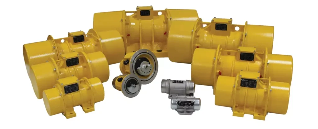
Furthermore, the vibrations of electrical machines may decrease the efficiency of the energy conversion because the vibration and possible related temperature rise are unwanted energy losses for the system. The vibrations of electrical machines can be divided into three categories: mechanical vibrations, electromagnetic vibrations, and aerodynamic vibrations. Benefitting from the continuous improvement of design and manufacturing level, the performance of electrical machines has been greatly improved and their volume has become very small. For the widely used small and medium-sized electrical machines, electromagnetic vibrations are the main type.
With the growth of living standards, people will pay more and more attention to the vibration of electrical machines. Investigating the vibration mechanism can be helpful for the design of electrical machines. Therefore, the study of the electromagnetic vibration of electrical machines has practical significance. Electromagnetic vibrations are usually generated by the distorted air-gap field of an eccentric rotor in electrical machines. The uneven air gap is directly related to eccentricity, which is common in rotating electrical machines.
Eccentricity can be caused by several reasons, such as relative misalignment of the rotor and stator in the fixing stage, misalignment of the load axis and rotor shaft, elliptical stator inner cross-section, wrong placement or rubbing of ball bearings, mechanical resonance, and unbalanced loads [1,2]. Eccentricities can be further subdivided into two categories: circumferential unequal air gaps and axial unequal air gaps. The former can be grouped into static eccentricity and dynamic eccentricity. In the case of static eccentricity, the rotor rotates around its own geometric axis, which is not the geometric axis of the stator.
In the case of dynamic eccentricity, the rotor is not concentric and rotates around the geometric axis of the stator. In reality, both static eccentricity and dynamic eccentricity tend to coexist. An inherent static eccentricity exists, even in newly manufactured machines, due to the build-up of tolerances during the manufacturing and assembly procedure, as has been reported in [3]. Unequal air gaps cause unbalanced magnetic forces (UMFs) [4] on the rotor, which lead to mechanical stress on some parts of the shaft and bearing.
Vibration Motor Price
After the prolonged operation, these factors cause broken mechanical parts or even the stator to rub the rotor, causing major breakdowns of the machines [5]. The calculation of UMF is essential for the analysis of vibrations and the optimal design of electrical rotating machinery. Two common approaches are the analytical method and the finite element
method (FEM).
Although the FEM has been widely applied to study the UMF [6,7], the analytical method still receives much attention because insights into the origins and pivotal factors in the production of UMF is provided by this method. Earlier publications focused primarily on the theoretical formulation of UMF and linear equations were mainly adopted. Werner [8] established a dynamic model for an induction motor with eccentric excitation by taking radial electromagnetic stiffness into account. The linear expressions are convincing only for cases where the eccentricity is small enough.
Therefore linear approaches are far from industrial applications. The nonlinear relationship between the UMF and eccentricity was pointed out in [9]. After that, many researchers have introduced nonlinear approaches to determine UMF in the last two decades. For instance, winding function analysis [10], conformal mapping method [11], energy conservation law [12], magnetic equivalent circuit method [13], and exact subdomain model [14] were all applied to investigate the magnetic field distribution and UMF for electrical machines with non-uniform air-gaps.
The most commonly adopted analytical method is the air-gap permeance approach [15,16]. An analytical expression of UMF for different pole pairs was obtained by expressing the air-gap permeance as a Fourier series in [15]. A calculation model for UMF was presented in [16] based on the actual position of the rotor inside the stator. It should be noted that the design and modeling of electrical machine systems are a multidisciplinary problem because electromagnetics, structural mechanics, and heat transfer are involved, and the design optimization process becomes more and more complex [17].
Therefore it is significant to pursue optimal system performance rather than optimal components such as motors or controllers because assembling individually optimized components into a system cannot ensure optimal performance for the whole system [18,19].
The problem is really a challenge for both the research and industrial communities since it includes not only theoretical multidisciplinary design and analysis (such as electromagnetic, thermal, mechanical analysis, and power electronics) but also practical engineering manufacturing of the system. Lei et al. [20] developed a robust approach for the system-level design optimization of the electrical machine system. Khan et al. [21] presented a multilevel design optimization framework to improve the efficiency of the proposed method by combining it with several techniques, such as the design of experiments and approximate models
The electromagnetic vibration of electrical machines has always been a hot topic in the mechanical discipline and electrical discipline fields, and there exist rich research results. The existing reviews of electromagnetic vibration are basically summarized from the view of fault diagnosis [22–27], and summaries from the perspective of dynamics are rather insufficient.
With the continuous progress of research, some new technologies and methods are emerging. It is necessary to generalize the latest research progress of electromagnetic vibration from the perspective of dynamics and vibration to avoid repetitive work. In addition, a review that provides systematic research outlines and references can be beneficial for the majority of scholars in this field to promote the ongoing progress and development of the investigations.
Different from the condition monitoring standpoint, this review is mainly concerned with the dynamic issues of electromagnetic vibrations in electrical machines. First, the vibration sources, which include the mechanical and electromagnetic aspects, are summarized in Section 2. Then Section 3 presents in detail different analytical and numerical calculation methods for electromagnetic force. After that, the electromagnetic vibration characteristics and experimental investigations are demonstrated in Section 4. Finally, Section 5 summarizes the authors’ thoughts about the trends and prospects of this research
Vibration motors are a type of motor that, as the name suggests, create a vibrating motion. They have become integral components in many modern devices and systems, providing feedback, alerts, and haptic responses that enhance user experience and functionality. These motors are designed to convert electrical energy into mechanical vibration, and they are used across various industries, including consumer electronics, automotive, medical devices, and industrial applications.
Historical Development
The history of vibration motors dates back to the early 20th century when basic mechanisms for generating vibration were first conceptualized. Over the years, technological advancements have led to more sophisticated designs, allowing for a wide range of applications. Early vibration motors were primarily used in industrial settings for tasks such as sorting and conveying materials. However, with the miniaturization of components and improvements in precision and control, they have become essential in everyday consumer electronics, providing tactile feedback and alerts in mobile devices and wearables.
Overview of Different Types of Vibration Motors
Vibration motors come in various types, each with unique characteristics and applications. The most common types include:
- Eccentric Rotating Mass (ERM) Motors: These motors generate vibration through the rotation of an off-center mass attached to the motor shaft. They are widely used in consumer electronics for simple haptic feedback.
- Linear Resonant Actuators (LRA): Unlike ERM motors, LRAs use a magnetic field to move a mass linearly, creating a more refined and precise vibration. This type is favored in applications requiring specific frequency responses and quick reaction times.
- Piezoelectric Vibration Motors: These utilize piezoelectric materials that expand or contract when an electrical voltage is applied. They offer high precision and are often used in applications requiring minimal size and power consumption.
This introduction sets the stage for a deeper exploration of the technical aspects, applications, and future developments of vibration motors.
Types of Vibration Motors
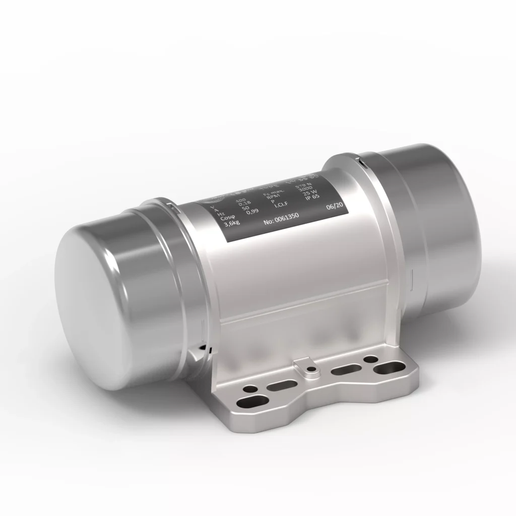
Understanding the different types of vibration motors is crucial for selecting the right one for a specific application. Each type has distinct characteristics that make it suitable for particular uses. This section explores the main types of vibration motors, their design, operation, and typical applications.
Eccentric Rotating Mass (ERM) Motors
Design and Operation
Eccentric Rotating Mass (ERM) motors are among the most widely used vibration motors. They operate by rotating an unbalanced mass, which generates centrifugal force, causing the motor to vibrate. The frequency and amplitude of the vibration are determined by the speed of rotation and the size of the mass.
The basic components of an ERM motor include:
- Motor Shaft: The central axis on which the unbalanced mass is mounted.
- Unbalanced Mass: The key component responsible for generating vibration. It is usually attached off-center on the motor shaft.
- Housing: Encloses the motor components, protecting them from environmental factors and mechanical damage.
ERM motors are relatively simple in design, making them cost-effective and easy to produce. They are typically used in applications where basic haptic feedback is needed, such as in mobile phones and handheld gaming devices.
Common Uses
- Mobile Phones and Tablets: ERM motors provide tactile feedback for touchscreen interactions and notifications.
- Wearable Devices: Used in smartwatches and fitness trackers to alert users with vibrations.
- Remote Controls: Enhance user experience by providing feedback during button presses.
Linear Resonant Actuators (LRA)
Design and Operation
Linear Resonant Actuators (LRA) are more advanced than ERM motors, offering improved precision and control. They consist of a movable mass attached to a spring and a magnetic field. When an AC voltage is applied, the mass oscillates linearly, creating a vibration.
Key components of LRA include:
- Movable Mass: Suspended by springs, this component moves back and forth to generate vibration.
- Electromagnetic Coil: Creates a magnetic field that interacts with the movable mass.
- Spring System: Ensures the mass returns to its original position after displacement.
LRA motors are known for their high-frequency response and efficiency, making them suitable for applications requiring precise control and fast response times.
Common Uses
- Haptic Feedback in Mobile Devices: Provides more nuanced and responsive feedback compared to ERM motors.
- Gaming Controllers: Enhances immersion by delivering realistic vibrations based on in-game events.
- Automotive Touchscreens: Improves user interaction with infotainment systems through tactile feedback.
Piezoelectric Vibration Motors
Design and Operation
Piezoelectric vibration motors leverage the piezoelectric effect, where certain materials generate an electric charge in response to mechanical stress. These motors consist of piezoelectric elements that deform when an electric field is applied, producing vibration.
Key components of piezoelectric motors include:
- Piezoelectric Elements: The core components that expand or contract to create vibration.
- Metal Plate: Acts as a diaphragm that vibrates in response to the deformation of the piezoelectric elements.
- Drive Circuit: Controls the frequency and amplitude of the applied voltage, affecting the vibration characteristics.
Piezoelectric motors are prized for their small size, low power consumption, and high precision. They are often used in applications where space is limited, and precise control is required.
Common Uses
- Medical Devices: Provide haptic feedback in surgical tools and diagnostic equipment.
- Consumer Electronics: Used in compact devices such as smartwatches and portable audio players.
- Industrial Sensors: Enhance sensitivity and accuracy in measurement instruments.
Comparison of Different Types
Each type of vibration motor has its advantages and disadvantages, influencing the selection process for specific applications.
| Type | Advantages | Disadvantages |
|---|---|---|
| ERM | – Simple design<br>- Cost-effective<br>- Easy to produce | – Limited frequency range<br>- Slower response time |
| LRA | – Precise control<br>- Fast response<br>- Efficient | – Higher cost<br>- More complex design |
| Piezoelectric | – Small size<br>- Low power consumption<br>- High precision | – Limited force output<br>- Requires specialized materials |
Selection Criteria for Different Applications
When selecting a vibration motor, several factors should be considered:
- Application Requirements: Determine the desired frequency, amplitude, and response time.
- Size and Weight: Consider the available space and weight constraints in the device or system.
- Power Consumption: Evaluate the power requirements, especially for battery-powered devices.
- Cost: Balance performance needs with budgetary constraints.
In summary, the choice of vibration motor depends on the specific application requirements, balancing factors such as performance, size, cost, and power consumption.
Technical Aspects of Vibration Motors
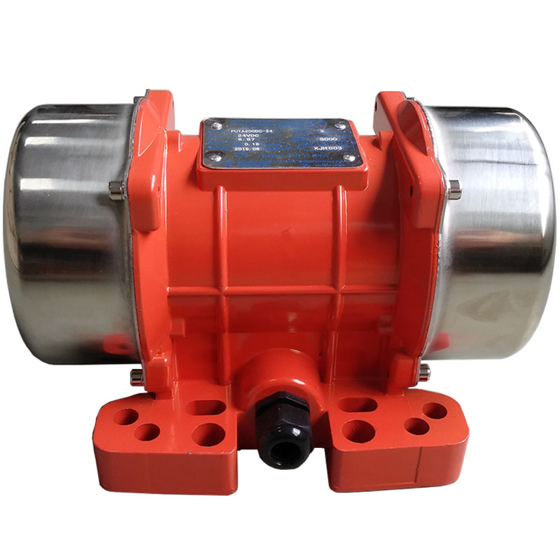
A comprehensive understanding of the technical aspects of vibration motors is essential for designing and integrating them into various applications. This section explores the construction, key specifications, performance characteristics, and design considerations associated with vibration motors.
Construction and Materials
Vibration motors are constructed using materials and components that ensure durability, efficiency, and performance. The choice of materials can significantly impact the motor’s lifespan and functionality.
Key Components
- Motor Housing: Typically made from metal or high-strength plastic, the housing protects the internal components from mechanical damage and environmental factors. It also serves as a mounting structure.
- Rotor and Stator: The rotor is the rotating part of the motor, while the stator is the stationary component. These are usually made from magnetic materials to facilitate electromagnetic interactions.
- Bearings: Bearings reduce friction between moving parts and support the motor shaft. They are often made from materials like stainless steel or ceramic for durability and reliability.
- Wiring and Connectors: Electrical connections are made using insulated copper wires and connectors that provide reliable electrical conductivity.
- Unbalanced Mass or Piezoelectric Elements: Depending on the type of motor, these components generate the vibrations. The unbalanced mass is typically made of metal, while piezoelectric elements are crafted from specialized ceramic materials.
Key Specifications
When selecting a vibration motor, several key specifications must be considered to ensure optimal performance for the intended application.
Size and Dimensions
- Length, Width, and Height: The overall dimensions of the motor must fit within the available space in the device or system.
- Weight: The motor’s weight can affect the balance and handling of the device, particularly in portable applications.
Power and Voltage
- Operating Voltage: The voltage required to power the motor, which can range from a few volts in small devices to several hundred volts in industrial applications.
- Power Consumption: The amount of electrical power consumed by the motor during operation. Lower power consumption is preferred for battery-powered devices.
Frequency and Amplitude
- Frequency Range: The range of vibration frequencies the motor can produce, typically measured in Hertz (Hz).
- Amplitude: The magnitude of the vibration, often expressed in millimeters (mm) or inches.
Performance Characteristics
Understanding the performance characteristics of vibration motors is crucial for achieving the desired vibration effects in various applications.
- Vibration Strength: The intensity of the vibration produced by the motor, influenced by factors such as motor speed, mass, and power input.
- Response Time: The time it takes for the motor to reach its desired vibration state after power is applied. Faster response times are preferred for applications requiring immediate feedback.
- Efficiency: The ratio of mechanical output power to electrical input power, indicating how effectively the motor converts electrical energy into vibration.
- Durability and Lifespan: The expected operational lifespan of the motor, affected by factors such as material quality, construction, and operating conditions.
Design Considerations and Challenges
Designing and integrating vibration motors into devices and systems involves several challenges and considerations to ensure optimal performance and reliability.
Heat Dissipation
Vibration motors generate heat during operation, which can affect their performance and lifespan. Effective heat dissipation methods, such as using heat sinks or conductive materials, are essential to prevent overheating.
Noise and Vibration Isolation
Unwanted noise and vibrations can interfere with the operation of devices and systems. Implementing noise and vibration isolation techniques, such as using damping materials or mounting systems, can minimize these issues.
Environmental Factors
Vibration motors may be exposed to various environmental factors, such as temperature extremes, moisture, and dust. Designing motors with protective features, such as seals or coatings, can enhance their resilience to environmental challenges.
Integration with Control Systems
Integrating vibration motors with control systems requires careful consideration of factors such as signal processing, power management, and feedback mechanisms. This ensures precise control and synchronization with other components in the system.
In conclusion, the technical aspects of vibration motors encompass a wide range of considerations, from construction and materials to performance characteristics and design challenges. Understanding these aspects is essential for selecting and implementing the right vibration motor for specific applications.
Applications of Vibration Motors
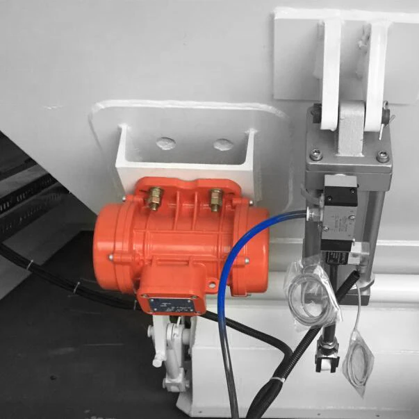
Vibration motors play a crucial role in various industries, enhancing functionality and user experience through tactile feedback, alerts, and precise control. This section explores the diverse applications of vibration motors across different sectors.
Consumer Electronics
Mobile Phones and Tablets
Vibration motors are integral components in mobile phones and tablets, providing haptic feedback for touchscreen interactions and notifications. They enhance the user experience by delivering tactile responses to touch inputs, alerts, and messages.
- Touchscreen Feedback: Vibration motors simulate the sensation of pressing physical buttons, improving user interaction with touchscreen interfaces.
- Notifications and Alerts: Vibration motors provide discreet alerts for incoming calls, messages, and notifications, allowing users to stay informed without relying on audible alerts.
Wearables and Smart Devices
In wearable technology, vibration motors are used to deliver notifications and alerts directly to the user’s wrist or body. This enhances the functionality and convenience of devices such as smartwatches and fitness trackers.
- Fitness Tracking: Vibration motors provide feedback for activity goals, heart rate monitoring, and other fitness metrics.
- Health Monitoring: Vibration alerts can signal important health-related notifications, such as medication reminders or emergency alerts.
Automotive Industry
Haptic Feedback in Touchscreens
Vibration motors are used in automotive touchscreens to enhance user interaction with infotainment and navigation systems. Haptic feedback provides tactile responses to touch inputs, improving usability and reducing driver distraction.
- Infotainment Systems: Vibration motors simulate button presses, enhancing the user experience and making interactions more intuitive.
- Navigation Controls: Haptic feedback assists drivers in navigating menus and settings, ensuring safer and more efficient operation.
Alert Systems
Vibration motors are employed in automotive alert systems to provide non-intrusive warnings and notifications to drivers. These systems enhance safety by delivering tactile alerts for various vehicle conditions and hazards.
- Collision Warning: Vibration alerts can warn drivers of potential collisions or obstacles, improving reaction times and safety.
- Lane Departure Warning: Vibration motors provide feedback when a vehicle deviates from its lane, helping drivers maintain proper lane positioning.
Industrial Applications
Equipment and Machinery Monitoring
In industrial settings, vibration motors are used for equipment and machinery monitoring. They provide feedback on the operational status and performance of machinery, helping to identify issues and prevent failures.
- Condition Monitoring: Vibration sensors detect changes in equipment performance, allowing for timely maintenance and repairs.
- Fault Detection: Vibration analysis helps identify mechanical faults, such as imbalances or misalignments, improving equipment reliability and efficiency.
Material Handling and Processing
Vibration motors are employed in material handling and processing applications, facilitating the movement and sorting of materials. They improve efficiency and accuracy in various industrial processes.
- Vibratory Conveyors: Vibration motors drive conveyors that transport materials, enhancing the speed and precision of material handling.
- Sorting and Screening: Vibration motors assist in sorting and screening materials based on size, weight, or other characteristics, optimizing production processes.
Medical Devices
Feedback Systems in Prosthetics
In the medical field, vibration motors are used in prosthetic devices to provide sensory feedback to users. This enhances the functionality and user experience of prosthetics, improving mobility and control.
- Tactile Feedback: Vibration motors simulate sensations such as touch and pressure, helping users interact with their environment.
- Control Feedback: Vibration alerts assist users in controlling prosthetic movements, enhancing precision and coordination.
Patient Monitoring Equipment
Vibration motors are employed in patient monitoring equipment to deliver alerts and notifications for various medical conditions. They improve patient care by providing timely and discreet notifications to healthcare professionals and patients.
- Vital Sign Monitoring: Vibration alerts signal changes in vital signs, such as heart rate or blood pressure, allowing for prompt medical intervention.
- Medication Reminders: Vibration motors provide reminders for medication administration, ensuring adherence to treatment plans.
Other Emerging Applications
Virtual Reality and Gaming
In virtual reality (VR) and gaming, vibration motors enhance immersion by delivering realistic tactile feedback based on in-game events and interactions. This improves the overall gaming experience and realism.
- Haptic Feedback in VR: Vibration motors simulate various sensations, such as impacts, textures, and environmental effects, enhancing the sense of presence in virtual environments.
- Gaming Controllers: Vibration motors provide feedback for in-game actions, such as explosions, collisions, and character movements, improving player engagement and satisfaction.
Robotics and Automation
Vibration motors are used in robotics and automation to enhance precision, control, and feedback in various applications. They improve the performance and functionality of robotic systems.
- Tactile Sensors: Vibration motors provide feedback for robotic grippers and manipulators, improving object handling and manipulation.
- Precision Control: Vibration alerts assist in fine-tuning robotic movements, enhancing accuracy and coordination in automated processes.
In conclusion, vibration motors have diverse applications across various industries, enhancing functionality, user experience, and performance. Their versatility and adaptability make them essential components in modern technology and systems.
Future Trends and Innovations
As technology continues to evolve, vibration motors are expected to undergo significant advancements, leading to new applications and improved performance. This section explores the future trends and innovations in vibration motor technology.
Technological Advancements
- Miniaturization: Advances in manufacturing and materials will enable the development of smaller and more compact vibration motors, expanding their use in miniaturized devices and systems.
- Increased Efficiency: Innovations in motor design and materials will lead to more efficient vibration motors with lower power consumption and higher performance.
- Improved Control and Precision: Enhanced control algorithms and sensor integration will enable more precise and customizable vibration effects, improving user experience and application performance.
Integration with IoT and Smart Technologies
The integration of vibration motors with the Internet of Things (IoT) and smart technologies will open up new possibilities for applications and functionality.
- Smart Home Devices: Vibration motors will provide tactile feedback and alerts in smart home devices, enhancing user interaction and control.
- Wearable Health Monitors: Integration with IoT will enable real-time monitoring and feedback for health and fitness applications, improving user outcomes and experiences.
Potential New Applications
- Augmented Reality (AR): Vibration motors will enhance AR experiences by providing tactile feedback for virtual interactions, improving immersion and realism.
- Advanced Automotive Systems: Vibration motors will play a role in advanced driver assistance systems (ADAS) and autonomous vehicles, providing feedback and alerts for various driving conditions and scenarios.
- Next-Generation Consumer Electronics: Vibration motors will continue to enhance user experience in emerging consumer electronics, such as foldable devices and flexible displays.
In summary, the future of vibration motors is promising, with advancements in technology and integration with smart systems leading to new applications and improved performance. These innovations will continue to enhance functionality and user experience across various industries.
Conclusion
Vibration motors are essential components in modern technology, providing tactile feedback, alerts, and precise control in a wide range of applications. This article has explored the various types of vibration motors, their technical aspects, and their diverse applications across industries.
Recap of Key Points
- Types of Vibration Motors: We examined the three main types of vibration motors—Eccentric Rotating Mass (ERM), Linear Resonant Actuators (LRA), and Piezoelectric vibration motors—each with unique characteristics and applications.
- Technical Aspects: We discussed the construction, key specifications, performance characteristics, and design considerations associated with vibration motors, highlighting the factors that influence their selection and integration.
- Applications: We explored the diverse applications of vibration motors in consumer electronics, automotive, industrial, medical, and other emerging fields, showcasing their versatility and adaptability.
- Future Trends and Innovations: We examined the future trends and innovations in vibration motor technology, including miniaturization, increased efficiency, and integration with IoT and smart technologies.
Importance of Vibration Motors in Modern Technology
Vibration motors play a crucial role in enhancing functionality and user experience across various industries. Their ability to provide tactile feedback, alerts, and precise control makes them indispensable components in modern devices and systems.
- Consumer Electronics: Vibration motors improve user interaction and experience in mobile phones, wearables, and other consumer devices.
- Automotive Industry: Vibration motors enhance safety and usability in automotive systems, providing feedback and alerts for various conditions.
- Industrial and Medical Applications: Vibration motors improve efficiency and performance in industrial processes and medical devices, providing valuable feedback and control.
Final Thoughts on Future Developments
As technology continues to advance, vibration motors will play an increasingly important role in emerging applications and industries. Innovations in design, materials, and integration will lead to new possibilities and improved performance, enhancing functionality and user experience.
In conclusion, vibration motors are vital components in modern technology, providing essential functionality and enhancing user experience across a wide range of applications. Their versatility, adaptability, and potential for future advancements make them indispensable in the ever-evolving technological landscape.
Introduction to Industrial Vibration Motors
Industrial vibration motors are specialized devices designed to generate mechanical vibrations for various industrial applications. They are integral to processes that require the movement, sorting, and monitoring of materials and equipment. By converting electrical energy into mechanical vibrations, these motors facilitate efficient material handling, quality control, and operational monitoring in industrial settings.
Key functions of industrial vibration motors include:
- Material Movement: Vibration motors aid in the transportation and handling of bulk materials, ensuring smooth and efficient processes.
- Sorting and Separation: They enhance the sorting and separation of materials based on size, weight, or other characteristics, optimizing production efficiency.
- Equipment Monitoring: Vibration motors provide feedback on the operational status of machinery, helping to identify potential issues before they lead to failures.
Historical Context
The use of vibration in industrial applications can be traced back to the early 20th century when basic vibrating mechanisms were employed for tasks such as material sorting and handling. The development of dedicated vibration motors, however, marked a significant advancement in technology.
- Early Innovations: Initial applications were primarily mechanical, relying on simple mechanisms to generate vibrations. These early systems were limited in precision and control.
- Technological Advancements: With the advent of electric motors and advancements in materials science, vibration motors became more sophisticated, offering improved control, efficiency, and versatility.
- Modern Applications: Today, industrial vibration motors are used across a wide range of industries, including mining, construction, food processing, and pharmaceuticals, highlighting their essential role in modern industrial processes.
Key Features
Industrial vibration motors are characterized by several key features that make them suitable for demanding applications:
- Robust Construction: Designed to withstand harsh industrial environments, vibration motors are built with durable materials and components.
- High Efficiency: They are engineered for optimal energy conversion, ensuring efficient performance and minimal energy loss.
- Versatility: Available in various sizes and configurations, vibration motors can be tailored to specific industrial needs and applications.
- Precision Control: Advanced control systems allow for precise adjustment of vibration frequency and amplitude, enabling customized solutions for diverse industrial tasks.
Key takeaways:
- Essential for Industrial Processes: Vibration motors are vital for efficient and effective material handling, sorting, and monitoring in industrial settings.
- Technological Evolution: From early mechanical systems to modern electric motors, technological advancements have significantly enhanced their capabilities.
- Diverse Applications: Used across multiple industries, vibration motors are adaptable to various tasks, showcasing their versatility and importance in modern industry.
Types of Industrial Vibration Motors
Understanding the different types of industrial vibration motors is crucial for selecting the appropriate motor for specific applications. Each type offers unique characteristics and advantages, making them suitable for various industrial tasks.
Eccentric Rotating Mass (ERM) Motors
Design and Operation
Eccentric Rotating Mass (ERM) motors are among the most commonly used vibration motors in industrial applications. They operate by rotating an unbalanced mass attached to the motor shaft, generating centrifugal force that produces vibration. The frequency and amplitude of the vibration are determined by the speed of rotation and the size of the unbalanced mass.
Key components of ERM motors include:
- Motor Shaft: The central axis on which the unbalanced mass is mounted.
- Unbalanced Mass: The component responsible for generating vibration. It is usually attached off-center on the motor shaft.
- Housing: Encloses the motor components, protecting them from environmental factors and mechanical damage.
Advantages of ERM motors:
- Simple Design: The straightforward design makes them easy to manufacture and maintain.
- Cost-Effective: They are relatively inexpensive compared to other types of vibration motors.
- Versatile Applications: Suitable for a wide range of industrial tasks, including material handling and sorting.
Common Applications
- Material Conveying: ERM motors drive vibratory conveyors, enhancing the movement of bulk materials.
- Screening and Sorting: They facilitate the sorting and screening of materials based on size and weight.
- Compact Equipment: ERM motors are used in applications where space is limited, providing efficient vibration solutions.
Linear Resonant Actuators (LRA)
Design and Operation
Linear Resonant Actuators (LRA) differ from ERM motors in that they generate vibration through the linear movement of a mass rather than rotational motion. An electromagnetic field is used to move the mass back and forth, producing vibrations with high precision and control.
Key components of LRA motors include:
- Movable Mass: Suspended by springs, the mass moves linearly to generate vibration.
- Electromagnetic Coil: Creates a magnetic field that interacts with the movable mass.
- Spring System: Ensures the mass returns to its original position after displacement.
Advantages of LRA motors:
- Precise Control: Offer more precise control over vibration frequency and amplitude.
- Efficient Performance: Consume less power compared to ERM motors, making them suitable for energy-sensitive applications.
- High-Frequency Response: Capable of producing high-frequency vibrations with minimal delay.
Common Applications
- Precision Manufacturing: Used in processes requiring exact vibration control, such as semiconductor manufacturing.
- Laboratory Equipment: Enhance the precision and accuracy of laboratory instruments and devices.
- Quality Control: Facilitate quality control processes by providing precise vibration feedback.
Electromagnetic Vibration Motors
Design and Operation
Electromagnetic vibration motors generate vibrations through the interaction of magnetic fields. These motors consist of an electromagnetic coil and a vibrating armature, which is set into motion by the magnetic field generated when current flows through the coil.
Key components of electromagnetic motors include:
- Electromagnetic Coil: Generates a magnetic field when energized.
- Vibrating Armature: Responds to the magnetic field, creating vibrations.
- Damping System: Reduces noise and unwanted vibrations, enhancing motor performance.
Advantages of electromagnetic motors:
- Smooth Operation: Provide smooth and continuous vibrations, reducing mechanical stress on components.
- Adjustable Frequency: Allow for precise control of vibration frequency and amplitude.
- Low Noise Levels: Operate with minimal noise, making them suitable for noise-sensitive environments.
Common Applications
- Conveying Systems: Used in conveyor systems for smooth and efficient material transportation.
- Vibratory Feeders: Enhance the performance of vibratory feeders used in packaging and assembly lines.
- Textile Industry: Improve the efficiency of textile processing equipment by providing consistent vibrations.
Piezoelectric Vibration Motors
Design and Operation
Piezoelectric vibration motors leverage the piezoelectric effect, where certain materials generate an electric charge in response to mechanical stress. These motors consist of piezoelectric elements that expand or contract when an electric field is applied, producing vibration.
Key components of piezoelectric motors include:
- Piezoelectric Elements: The core components that expand or contract to create vibration.
- Metal Plate: Acts as a diaphragm that vibrates in response to the deformation of the piezoelectric elements.
- Drive Circuit: Controls the frequency and amplitude of the applied voltage, affecting the vibration characteristics.
Advantages of piezoelectric motors:
- High Precision: Offer precise control over vibration characteristics, making them suitable for sensitive applications.
- Compact Design: Small and lightweight, ideal for applications with space constraints.
- Low Power Consumption: Require minimal power, making them energy-efficient.
Common Applications
- Medical Devices: Provide precise vibration feedback in medical diagnostic equipment.
- Microelectronics: Enhance the performance of microelectronic devices by providing controlled vibrations.
- Research and Development: Used in experimental setups requiring precise vibration control.
Comparison of Types
Each type of industrial vibration motor has its own set of advantages and disadvantages, influencing their suitability for specific applications.
| Type | Advantages | Disadvantages |
|---|---|---|
| ERM | – Simple design<br>- Cost-effective<br>- Versatile | – Limited frequency range<br>- Slower response time |
| LRA | – Precise control<br>- High efficiency<br>- Fast response | – Higher cost<br>- More complex design |
| Electromagnetic | – Smooth operation<br>- Adjustable frequency<br>- Low noise | – Complex construction<br>- Requires precise alignment |
| Piezoelectric | – High precision<br>- Compact design<br>- Low power consumption | – Limited force output<br>- Specialized materials required |
Selection Criteria:
- Application Requirements: Determine the desired frequency, amplitude, and response time.
- Size and Weight: Consider the available space and weight constraints in the application.
- Power Consumption: Evaluate the power requirements, especially for energy-sensitive applications.
- Cost: Balance performance needs with budgetary constraints.
Summary:
- Diverse Options: A variety of vibration motors are available, each with unique characteristics and advantages.
- Application-Specific Selection: The choice of motor depends on the specific requirements and constraints of the application.
Technical Aspects of Industrial Vibration Motors
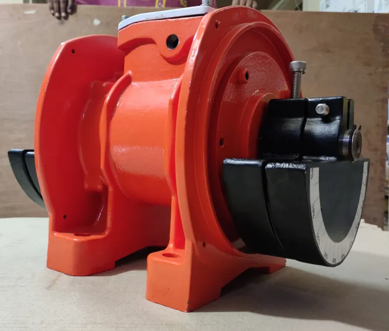
A comprehensive understanding of the technical aspects of industrial vibration motors is essential for designing and integrating them into various applications. This section explores the construction, key specifications, performance characteristics, and design considerations associated with vibration motors.
Construction and Materials
Industrial vibration motors are constructed using materials and components that ensure durability, efficiency, and performance. The choice of materials can significantly impact the motor’s lifespan and functionality.
Key Components
- Motor Housing: Typically made from metal or high-strength plastic, the housing protects the internal components from mechanical damage and environmental factors. It also serves as a mounting structure.
- Rotor and Stator: The rotor is the rotating part of the motor, while the stator is the stationary component. These are usually made from magnetic materials to facilitate electromagnetic interactions.
- Bearings: Bearings reduce friction between moving parts and support the motor shaft. They are often made from materials like stainless steel or ceramic for durability and reliability.
- Wiring and Connectors: Electrical connections are made using insulated copper wires and connectors that provide reliable electrical conductivity.
- Unbalanced Mass or Piezoelectric Elements: Depending on the type of motor, these components generate the vibrations. The unbalanced mass is typically made of metal, while piezoelectric elements are crafted from specialized ceramic materials.
Key Specifications
When selecting a vibration motor, several key specifications must be considered to ensure optimal performance for the intended application.
Size and Dimensions
- Length, Width, and Height: The overall dimensions of the motor must fit within the available space in the device or system.
- Weight: The motor’s weight can affect the balance and handling of the device, particularly in portable applications.
Power and Voltage
- Operating Voltage: The voltage required to power the motor, which can range from a few volts in small devices to several hundred volts in industrial applications.
- Power Consumption: The amount of electrical power consumed by the motor during operation. Lower power consumption is preferred for battery-powered devices.
Frequency and Amplitude
- Frequency Range: The range of vibration frequencies the motor can produce, typically measured in Hertz (Hz).
- Amplitude: The magnitude of the vibration, often expressed in millimeters (mm) or inches.
Performance Characteristics
Understanding the performance characteristics of vibration motors is crucial for achieving the desired vibration effects in various applications.
- Vibration Strength: The intensity of the vibration produced by the motor, influenced by factors such as motor speed, mass, and power input.
- Response Time: The time it takes for the motor to reach its desired vibration state after power is applied. Faster response times are preferred for applications requiring immediate feedback.
- Efficiency: The ratio of mechanical output power to electrical input power, indicating how effectively the motor converts electrical energy into vibration.
- Durability and Lifespan: The expected operational lifespan of the motor, affected by factors such as material quality, construction, and operating conditions.
Design Considerations and Challenges
Designing and integrating vibration motors into devices and systems involves several challenges and considerations to ensure optimal performance and reliability.
Heat Dissipation
Vibration motors generate heat during operation, which can affect their performance and lifespan. Effective heat dissipation methods, such as using heat sinks or conductive materials, are essential to prevent overheating.
Noise and Vibration Isolation
Unwanted noise and vibrations can interfere with the operation of devices and systems. Implementing noise and vibration isolation techniques, such as using damping materials or mounting systems, can minimize these issues.
Environmental Factors
Vibration motors may be exposed to various environmental factors, such as temperature extremes, moisture, and dust. Designing motors with protective features, such as seals or coatings, can enhance their resilience to environmental challenges.
Integration with Control Systems
Integrating vibration motors with control systems requires careful consideration of factors such as signal processing, power management, and feedback mechanisms. This ensures precise control and synchronization with other components in the system.
In conclusion, the technical aspects of vibration motors encompass a wide range of considerations, from construction and materials to performance characteristics and design challenges. Understanding these aspects is essential for selecting and implementing the right vibration motor for specific applications.
Applications of Industrial Vibration Motors
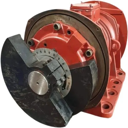
Industrial vibration motors play a crucial role in enhancing efficiency, productivity, and quality across various industries. This section explores the diverse applications of vibration motors in industrial settings.
Material Handling and Processing
Vibratory Conveyors
Vibration motors are integral components of vibratory conveyors, which are used to transport bulk materials efficiently. By generating controlled vibrations, these motors facilitate the smooth movement of materials, reducing friction and wear on conveyor surfaces.
- Efficient Transportation: Vibration motors enable the continuous flow of materials, minimizing downtime and increasing throughput.
- Versatile Applications: Vibratory conveyors are used in industries such as food processing, pharmaceuticals, and mining, where precise material handling is essential.
Screening and Sorting
In screening and sorting applications, vibration motors enhance the separation of materials based on size, weight, or other characteristics. They drive vibratory screens and separators, ensuring accurate and efficient sorting processes.
- Improved Accuracy: Vibration motors provide consistent and controlled vibrations, improving the accuracy of sorting and screening operations.
- Customizable Solutions: Adjustable frequency and amplitude settings allow for tailored solutions to meet specific sorting requirements.
Feeding and Dosing
Vibration motors are used in feeding and dosing applications to deliver precise amounts of materials to processing equipment. They drive vibratory feeders, ensuring accurate and consistent material flow.
- Precise Control: Vibration motors enable precise control over material flow rates, enhancing the efficiency of production processes.
- Reduced Waste: Accurate dosing reduces material waste, improving overall production efficiency and sustainability.
Machinery and Equipment Monitoring
Condition Monitoring
Vibration motors are employed in condition monitoring systems to assess the operational status of machinery and equipment. They provide feedback on vibration levels, helping to identify potential issues before they lead to failures.
- Early Fault Detection: Vibration analysis can detect mechanical faults, such as imbalances, misalignments, and bearing wear, allowing for timely maintenance and repairs.
- Improved Equipment Reliability: Regular monitoring of vibration levels enhances equipment reliability and longevity, reducing downtime and maintenance costs.
Predictive Maintenance
In predictive maintenance applications, vibration motors play a key role in monitoring the health of machinery and equipment. They provide real-time data on vibration patterns, enabling proactive maintenance strategies.
- Reduced Downtime: Predictive maintenance minimizes unexpected equipment failures, reducing downtime and production disruptions.
- Cost Savings: By addressing issues before they escalate, predictive maintenance reduces maintenance costs and extends equipment lifespan.
Mining and Quarrying
Material Transportation
In the mining and quarrying industry, vibration motors are used to transport bulk materials, such as ore and aggregates, over long distances. They drive vibratory feeders and conveyors, ensuring efficient material handling.
- High-Capacity Transportation: Vibration motors enable the transportation of large volumes of materials, increasing production efficiency.
- Durable Solutions: Designed for harsh environments, vibration motors provide reliable performance in demanding mining and quarrying applications.
Screening and Classification
Vibration motors are employed in screening and classification processes to separate materials based on size and composition. They drive vibratory screens and separators, ensuring accurate classification of materials.
- Accurate Classification: Vibration motors provide consistent and controlled vibrations, improving the accuracy of screening and classification operations.
- Adaptable Solutions: Adjustable frequency and amplitude settings allow for tailored solutions to meet specific classification requirements.
Construction Industry
Concrete Compaction
In the construction industry, vibration motors are used to compact concrete, ensuring uniform density and strength. They drive vibratory compactors and tampers, improving the quality of concrete structures.
- Improved Concrete Quality: Vibration motors enhance concrete compaction, reducing voids and increasing structural integrity.
- Efficient Construction Processes: Vibration motors streamline concrete compaction, reducing labor costs and construction time.
Soil Compaction
Vibration motors are employed in soil compaction applications to improve soil stability and load-bearing capacity. They drive vibratory rollers and compactors, enhancing the performance of construction equipment.
- Enhanced Soil Stability: Vibration motors improve soil compaction, increasing stability and load-bearing capacity.
- Versatile Applications: Used in road construction, foundation preparation, and landscaping, vibration motors provide adaptable solutions for various soil compaction needs.
Food and Beverage Industry
Food Processing
In the food and beverage industry, vibration motors are used to enhance food processing operations. They drive vibratory conveyors and feeders, ensuring efficient and hygienic material handling.
- Efficient Material Handling: Vibration motors enable the smooth and consistent flow of food products, reducing processing time and waste.
- Hygienic Solutions: Designed for easy cleaning and maintenance, vibration motors ensure hygienic food processing operations.
Packaging and Sorting
Vibration motors are employed in packaging and sorting applications to enhance efficiency and accuracy. They drive vibratory sorters and packers, ensuring precise material handling.
- Improved Sorting Accuracy: Vibration motors provide controlled vibrations, improving the accuracy of packaging and sorting operations.
- Customizable Solutions: Adjustable frequency and amplitude settings allow for tailored solutions to meet specific packaging and sorting requirements.
Pharmaceutical Industry
Tablet Coating
In the pharmaceutical industry, vibration motors are used to enhance tablet coating processes. They drive vibratory coaters, ensuring uniform coating application.
- Improved Coating Quality: Vibration motors ensure uniform coating thickness, improving the quality and efficacy of pharmaceutical products.
- Efficient Production Processes: Vibration motors streamline tablet coating, reducing production time and costs.
Capsule Filling
Vibration motors are employed in capsule filling applications to enhance accuracy and efficiency. They drive vibratory fillers, ensuring precise material dosing.
- Accurate Dosing: Vibration motors enable precise control over material flow rates, improving the accuracy of capsule filling operations.
- Reduced Waste: Accurate dosing reduces material waste, improving overall production efficiency and sustainability.
In conclusion, industrial vibration motors have diverse applications across various industries, enhancing efficiency, productivity, and quality. Their versatility and adaptability make them essential components in modern industrial processes.
Challenges and Solutions in Industrial Applications
Industrial vibration motors are subject to various challenges that can impact their performance and reliability. This section explores common challenges in industrial applications and potential solutions to address them.
Environmental Considerations
Harsh Operating Conditions
Industrial environments can expose vibration motors to harsh conditions, such as extreme temperatures, moisture, dust, and chemicals. These factors can affect motor performance and longevity.
Solutions:
- Protective Coatings: Apply protective coatings to motor components to resist corrosion and wear.
- Sealed Enclosures: Use sealed enclosures to protect internal components from environmental factors.
- Temperature Management: Implement cooling systems or heat sinks to manage temperature fluctuations.
Vibration-Induced Fatigue
Continuous vibration exposure can lead to fatigue and wear on motor components, reducing their lifespan and reliability.
Solutions:
- Durable Materials: Use high-strength materials and components designed to withstand vibration-induced fatigue.
- Regular Maintenance: Implement routine maintenance schedules to identify and address wear and fatigue early.
- Vibration Dampening: Incorporate vibration dampening techniques, such as shock absorbers or isolators, to reduce stress on components.
Maintenance and Longevity
Wear and Tear
Vibration motors are subject to wear and tear due to constant operation, which can impact performance and reliability.
Solutions:
- High-Quality Components: Use high-quality bearings, seals, and other components to minimize wear and tear.
- Lubrication: Implement proper lubrication practices to reduce friction and extend component lifespan.
- Preventive Maintenance: Conduct regular inspections and maintenance to identify and address potential issues before they escalate.
Unexpected Failures
Unexpected motor failures can lead to downtime and production disruptions, impacting productivity and profitability.
Solutions:
- Condition Monitoring: Implement condition monitoring systems to assess motor health and detect potential issues early.
- Predictive Maintenance: Use predictive maintenance strategies to anticipate and address issues before they result in failures.
- Redundancy: Incorporate redundancy in critical applications to minimize the impact of motor failures.
Noise and Vibration Control
Unwanted Noise
Vibration motors can generate unwanted noise, impacting the working environment and operator comfort.
Solutions:
- Noise Reduction Techniques: Implement noise reduction techniques, such as damping materials or enclosures, to minimize noise levels.
- Precision Engineering: Use precision-engineered components and designs to reduce mechanical noise.
- Isolation: Isolate motors from other components to prevent noise transmission.
Vibration Transmission
Uncontrolled vibration transmission can affect the performance of other equipment and systems, leading to inefficiencies and failures.
Solutions:
- Vibration Isolation: Use vibration isolation techniques, such as mounts or shock absorbers, to reduce vibration transmission.
- Balancing: Ensure motors and components are properly balanced to minimize vibration transmission.
- Control Systems: Implement advanced control systems to manage and adjust vibration characteristics.
In conclusion, industrial vibration motors face various challenges in harsh operating environments. By implementing appropriate solutions, such as protective measures, maintenance strategies, and noise control techniques, these challenges can be effectively addressed, ensuring reliable and efficient motor performance.
Future Trends and Innovations
As technology continues to evolve, industrial vibration motors are expected to undergo significant advancements, leading to new applications and improved performance. This section explores future trends and innovations in vibration motor technology.
Technological Advancements
- Miniaturization: Advances in manufacturing and materials will enable the development of smaller and more compact vibration motors, expanding their use in miniaturized devices and systems.
- Increased Efficiency: Innovations in motor design and materials will lead to more efficient vibration motors with lower power consumption and higher performance.
- Improved Control and Precision: Enhanced control algorithms and sensor integration will enable more precise and customizable vibration effects, improving user experience and application performance.
Integration with Smart Technologies
The integration of vibration motors with the Internet of Things (IoT) and smart technologies will open up new possibilities for applications and functionality.
- Smart Manufacturing: Vibration motors will play a key role in smart manufacturing processes, enabling real-time monitoring and control of production systems.
- Automated Systems: Integration with smart technologies will enhance the performance and efficiency of automated systems, improving productivity and quality.
Emerging Applications
- Advanced Robotics: Vibration motors will enhance the performance of advanced robotic systems, providing precise control and feedback for complex tasks.
- Augmented Reality (AR): Vibration motors will enhance AR experiences by providing tactile feedback for virtual interactions, improving immersion and realism.
- Next-Generation Industrial Equipment: Vibration motors will continue to enhance the performance of next-generation industrial equipment, such as 3D printers and advanced manufacturing systems.
In summary, the future of industrial vibration motors is promising, with advancements in technology and integration with smart systems leading to new applications and improved performance. These innovations will continue to enhance functionality and efficiency across various industries.
Conclusion
Industrial vibration motors are essential components in modern technology, providing crucial functionality and enhancing efficiency across a wide range of applications. This article has explored the various types of vibration motors, their technical aspects, and their diverse applications in industrial settings.
Recap of Key Points
- Types of Vibration Motors: We examined the different types of industrial vibration motors, each with unique characteristics and advantages.
- Technical Aspects: We discussed the construction, key specifications, performance characteristics, and design considerations associated with vibration motors, highlighting the factors that influence their selection and integration.
- Applications: We explored the diverse applications of vibration motors in industries such as material handling, mining, construction, and pharmaceuticals, showcasing their versatility and importance in modern industry.
- Challenges and Solutions: We identified common challenges in industrial applications and provided solutions to address them, ensuring reliable and efficient motor performance.
- Future Trends and Innovations: We examined the future trends and innovations in vibration motor technology, including miniaturization, increased efficiency, and integration with smart technologies.
Importance in Modern Industry
Industrial vibration motors play a crucial role in enhancing efficiency, productivity, and quality across various industries. Their ability to provide precise control, feedback, and motion makes them indispensable components in modern industrial processes.
- Material Handling: Vibration motors improve the efficiency of material handling operations, enhancing productivity and reducing costs.
- Machinery Monitoring: Vibration motors enable real-time monitoring and maintenance of machinery, improving equipment reliability and longevity.
- Diverse Applications: From mining to pharmaceuticals, vibration motors are used in a wide range of applications, highlighting their versatility and adaptability.
Future Outlook
As technology continues to advance, industrial vibration motors will play an increasingly important role in emerging applications and industries. Innovations in design, materials, and integration will lead to new possibilities and improved performance, enhancing functionality and efficiency across various sectors.
In conclusion, industrial vibration motors are vital components in modern technology, providing essential functionality and enhancing efficiency across a wide range of applications. Their versatility, adaptability, and potential for future advancements make them indispensable in the ever-evolving industrial landscape.
Introduction to Energy Consumption
Creating an informative article on energy consumption tips can help individuals and businesses save money, reduce their environmental impact, and improve overall energy efficiency. Below is a comprehensive 5000-word article suitable for a professional website, covering various aspects of energy consumption tips:
Energy consumption refers to the total amount of energy used by individuals, households, businesses, and industries. It encompasses various forms of energy, including electricity, natural gas, oil, and renewable energy sources. Understanding energy consumption is crucial for identifying areas where efficiency can be improved, leading to cost savings and environmental benefits.
Key aspects of energy consumption include:
- Types of Energy: Energy consumption can be categorized into different types, such as electrical, thermal, and mechanical energy, each serving specific purposes in daily activities and industrial processes.
- Energy Sources: Energy can be derived from various sources, including fossil fuels (coal, oil, natural gas) and renewable sources (solar, wind, geothermal, biomass, hydroelectric).
- Energy Demand: The demand for energy varies based on factors such as population, economic activity, climate, and technological advancements.
Importance of Energy Efficiency
Energy efficiency involves using less energy to perform the same tasks, reducing energy waste, and minimizing the environmental impact of energy use. It is a critical component of sustainable development and offers numerous benefits:
- Cost Savings: Improving energy efficiency can lead to significant reductions in energy bills, benefiting households, businesses, and industries.
- Environmental Benefits: Reducing energy consumption decreases greenhouse gas emissions and reduces reliance on fossil fuels, mitigating the impact of climate change.
- Resource Conservation: Energy efficiency helps conserve natural resources by reducing the demand for energy production and consumption.
- Energy Security: Efficient energy use reduces dependence on imported energy sources, enhancing energy security and resilience.
Benefits of Reducing Energy Consumption
Reducing energy consumption offers a wide range of benefits, including:
- Financial Savings: Lower energy bills result in financial savings for individuals, businesses, and governments, freeing up resources for other investments and initiatives.
- Environmental Protection: Reduced energy consumption leads to lower emissions of pollutants and greenhouse gases, contributing to cleaner air and a healthier environment.
- Improved Comfort and Quality of Life: Energy-efficient homes and buildings provide enhanced comfort, improved indoor air quality, and better thermal regulation.
- Economic Growth: Energy efficiency can drive economic growth by creating jobs in energy-efficient technologies, renewable energy, and sustainable practices.
Key takeaways:
- Essential for Sustainability: Energy consumption is a critical aspect of modern life, and improving energy efficiency is essential for achieving sustainable development.
- Diverse Benefits: Reducing energy consumption offers financial, environmental, and social benefits, making it a valuable goal for individuals, businesses, and governments.
Energy Consumption in Residential Settings
Improving energy efficiency in residential settings can lead to significant cost savings and environmental benefits. This section explores various strategies for reducing energy consumption in homes.
Heating and Cooling
Heating and cooling account for a significant portion of residential energy consumption. Implementing energy-efficient practices can lead to substantial savings:
- Programmable Thermostats: Use programmable thermostats to set specific temperature schedules, reducing energy use when heating or cooling is not needed.
- Example: Set the thermostat to lower the temperature during the winter when you’re asleep or away from home and raise it during the summer.
- Benefits: Reduces energy consumption by adjusting heating and cooling based on occupancy patterns.
- Regular Maintenance: Ensure heating and cooling systems are regularly maintained, including cleaning filters, checking ducts, and servicing equipment.
- Example: Schedule annual maintenance for HVAC systems to ensure they operate efficiently.
- Benefits: Increases the efficiency and lifespan of heating and cooling equipment.
- Insulation and Sealing: Improve insulation in walls, attics, and basements, and seal gaps and cracks to prevent air leaks.
- Example: Use weatherstripping to seal doors and windows, and add insulation to attics.
- Benefits: Reduces heat loss in winter and heat gain in summer, improving comfort and reducing energy use.
- Energy-Efficient HVAC Systems: Consider upgrading to energy-efficient heating and cooling systems, such as heat pumps and high-efficiency furnaces.
- Example: Replace an older furnace with an ENERGY STAR-certified model that offers improved efficiency.
- Benefits: Reduces energy consumption and provides consistent heating and cooling performance.
Lighting
Lighting is another significant contributor to residential energy consumption. Implementing energy-efficient lighting solutions can lead to substantial savings:
- LED Lighting: Replace incandescent and fluorescent bulbs with LED lighting, which uses less energy and lasts longer.
- Example: Install LED bulbs in all light fixtures, including lamps, overhead lights, and outdoor lighting.
- Benefits: Reduces energy consumption, lowers electricity bills, and reduces the need for frequent bulb replacements.
- Motion Sensors and Timers: Use motion sensors and timers to automatically turn off lights when not in use, reducing energy waste.
- Example: Install motion sensors in areas with infrequent use, such as hallways and closets, to automatically turn off lights.
- Benefits: Eliminates energy waste by ensuring lights are only on when needed.
- Natural Lighting: Maximize natural lighting by using windows, skylights, and light-colored interior finishes to reduce the need for artificial lighting.
- Example: Use sheer curtains to allow natural light to enter while maintaining privacy.
- Benefits: Reduces the need for artificial lighting, improving energy efficiency and enhancing indoor ambiance.
- Lighting Controls: Implement lighting controls, such as dimmers and smart switches, to adjust lighting levels based on needs and preferences.
- Example: Install dimmer switches in living areas to control lighting intensity and create desired atmospheres.
- Benefits: Allows for customized lighting levels, reducing energy consumption and enhancing comfort.
Appliances and Electronics
Appliances and electronics account for a significant portion of residential energy use. Implementing energy-efficient practices can lead to significant savings:
- ENERGY STAR Appliances: Choose ENERGY STAR-certified appliances, which meet strict energy efficiency standards and consume less energy.
- Example: Replace an old refrigerator with an ENERGY STAR-certified model that offers improved efficiency.
- Benefits: Reduces energy consumption and lowers electricity bills.
- Unplugging Devices: Unplug devices and chargers when not in use to eliminate standby power consumption, also known as “phantom load.”
- Example: Use power strips to easily turn off multiple devices and chargers when not in use.
- Benefits: Reduces energy waste and lowers electricity bills.
- Efficient Use of Appliances: Use appliances efficiently, such as running full loads in dishwashers and washing machines and using cold water for laundry.
- Example: Wash clothes in cold water and air dry when possible to save energy.
- Benefits: Reduces energy consumption and extends the lifespan of appliances.
- Smart Home Technology: Implement smart home technology to monitor and control appliance energy use, allowing for optimized energy management.
- Example: Use a smart thermostat to control heating and cooling remotely and adjust settings based on occupancy patterns.
- Benefits: Provides greater control over energy use, reducing waste and lowering energy bills.
Water Heating
Water heating is another significant contributor to residential energy consumption. Implementing energy-efficient practices can lead to substantial savings:
- Tankless Water Heaters: Consider installing tankless water heaters, which provide hot water on demand and eliminate standby energy loss.
- Example: Replace a traditional tank water heater with a tankless model that heats water as needed.
- Benefits: Reduces energy consumption and provides continuous hot water supply.
- Water Heater Insulation: Insulate water heater tanks and pipes to reduce heat loss and improve efficiency.
- Example: Install a water heater blanket and insulate hot water pipes to minimize heat loss.
- Benefits: Reduces energy consumption and improves water heating efficiency.
- Lower Water Heater Temperature: Set the water heater temperature to 120°F (49°C) to reduce energy use while maintaining comfort.
- Example: Adjust the thermostat on the water heater to maintain a temperature of 120°F.
- Benefits: Reduces energy consumption and lowers the risk of scalding.
- Efficient Water Use: Implement water-saving practices, such as shorter showers and using low-flow fixtures, to reduce hot water demand.
- Example: Install low-flow showerheads and faucets to reduce water use without sacrificing comfort.
- Benefits: Reduces hot water demand and lowers energy consumption.
Insulation and Sealing
Improving insulation and sealing in residential settings can lead to significant energy savings:
- Wall and Attic Insulation: Improve insulation in walls, attics, and basements to reduce heat loss and gain.
- Example: Add insulation to attics and walls to improve thermal performance and comfort.
- Benefits: Reduces heating and cooling energy consumption and improves indoor comfort.
- Window and Door Sealing: Seal gaps and cracks around windows and doors to prevent air leaks and improve energy efficiency.
- Example: Use weatherstripping and caulking to seal gaps around windows and doors.
- Benefits: Reduces heat loss and gain, improving energy efficiency and comfort.
- Energy-Efficient Windows: Consider upgrading to energy-efficient windows with low-emissivity (Low-E) coatings and double glazing.
- Example: Replace single-pane windows with ENERGY STAR-certified double-pane windows.
- Benefits: Reduces heat transfer and improves energy efficiency.
- Roof and Floor Insulation: Improve insulation in roofs and floors to reduce heat loss and gain, enhancing energy efficiency.
- Example: Install reflective roof coatings and floor insulation to improve thermal performance.
- Benefits: Reduces heating and cooling energy consumption and improves comfort.
In summary, improving energy efficiency in residential settings involves a combination of technology, practices, and behavioral changes. By implementing energy-efficient solutions for heating, cooling, lighting, appliances, and insulation, homeowners can achieve significant cost savings and environmental benefits.
Energy Consumption in Commercial and Industrial Settings
Improving energy efficiency in commercial and industrial settings can lead to significant cost savings, enhanced productivity, and environmental benefits. This section explores various strategies for reducing energy consumption in businesses and industries.
Energy Audits and Monitoring
Conducting energy audits and implementing energy monitoring systems are essential steps in identifying areas for improvement and optimizing energy use.
- Energy Audits: Conduct comprehensive energy audits to assess energy use, identify inefficiencies, and recommend improvements.
- Example: Hire a professional energy auditor to evaluate energy use in a commercial building and provide recommendations for efficiency improvements.
- Benefits: Identifies areas for improvement and provides actionable insights for reducing energy consumption.
- Energy Monitoring Systems: Implement energy monitoring systems to track energy use in real-time, identify trends, and optimize energy management.
- Example: Use energy monitoring software to track electricity use in an industrial facility and identify peak demand periods.
- Benefits: Provides real-time data for informed decision-making and energy optimization.
- Benchmarking: Compare energy use against industry benchmarks and standards to identify areas for improvement and set energy efficiency goals.
- Example: Use energy benchmarking tools to compare energy use in a commercial building against similar facilities.
- Benefits: Identifies opportunities for improvement and sets achievable energy efficiency goals.
- Continuous Improvement: Implement a continuous improvement process for energy management, regularly reviewing energy use and implementing efficiency measures.
- Example: Establish an energy management team to review energy use, set goals, and implement efficiency measures.
- Benefits: Ensures ongoing optimization of energy use and continuous improvement.
Lighting Solutions
Implementing energy-efficient lighting solutions can lead to substantial savings in commercial and industrial settings.
- LED Lighting: Replace traditional lighting with LED lighting, which uses less energy and lasts longer.
- Example: Install LED lighting in offices, warehouses, and manufacturing facilities to reduce energy consumption.
- Benefits: Reduces energy consumption, lowers electricity bills, and reduces maintenance costs.
- Daylighting: Maximize natural daylighting through the use of windows, skylights, and light tubes, reducing the need for artificial lighting.
- Example: Install skylights in warehouses and manufacturing facilities to maximize natural lighting.
- Benefits: Reduces the need for artificial lighting, improving energy efficiency and enhancing indoor ambiance.
- Lighting Controls: Implement lighting controls, such as motion sensors, timers, and dimmers, to optimize lighting use based on occupancy and needs.
- Example: Install motion sensors in restrooms and storage areas to automatically turn off lights when not in use.
- Benefits: Eliminates energy waste and reduces electricity bills.
- Task Lighting: Use task lighting in workspaces to provide focused illumination, reducing the need for overhead lighting.
- Example: Install task lighting at individual workstations to provide focused illumination for tasks.
- Benefits: Reduces overall lighting energy consumption and enhances comfort.
HVAC Systems
Heating, ventilation, and air conditioning (HVAC) systems are major contributors to energy consumption in commercial and industrial settings. Implementing energy-efficient HVAC solutions can lead to substantial savings:
- Regular Maintenance: Ensure HVAC systems are regularly maintained, including cleaning filters, checking ducts, and servicing equipment.
- Example: Schedule annual maintenance for HVAC systems to ensure they operate efficiently.
- Benefits: Increases the efficiency and lifespan of HVAC equipment.
- Energy-Efficient HVAC Systems: Upgrade to energy-efficient HVAC systems, such as high-efficiency heat pumps, chillers, and boilers.
- Example: Replace an older HVAC system with an ENERGY STAR-certified model that offers improved efficiency.
- Benefits: Reduces energy consumption and provides consistent heating and cooling performance.
- Zoning Systems: Implement zoning systems to control heating and cooling in specific areas, reducing energy use in unoccupied or low-traffic areas.
- Example: Use zoning controls to manage temperature settings in different areas of a building based on occupancy patterns.
- Benefits: Reduces energy consumption and enhances comfort.
- Building Automation Systems: Use building automation systems to monitor and control HVAC systems, optimizing energy use based on occupancy and needs.
- Example: Implement a building automation system to adjust HVAC settings based on occupancy patterns and external conditions.
- Benefits: Provides greater control over energy use, reducing waste and lowering energy bills.
Industrial Equipment and Machinery
Improving the energy efficiency of industrial equipment and machinery can lead to significant cost savings and environmental benefits.
- Variable Frequency Drives (VFDs): Install variable frequency drives on motors to optimize speed and reduce energy consumption.
- Example: Install VFDs on pumps and fans to adjust motor speed based on demand.
- Benefits: Reduces energy consumption and extends the lifespan of motors.
- Energy-Efficient Motors: Upgrade to energy-efficient motors that consume less energy and provide improved performance.
- Example: Replace older motors with high-efficiency models that meet or exceed industry standards.
- Benefits: Reduces energy consumption and lowers maintenance costs.
- Compressed Air Systems: Optimize compressed air systems to reduce energy consumption and improve efficiency.
- Example: Conduct regular maintenance, repair leaks, and adjust pressure settings in compressed air systems.
- Benefits: Reduces energy waste and improves system performance.
- Efficient Use of Equipment: Implement practices to optimize the use of industrial equipment, such as scheduling maintenance during off-peak hours and reducing idle time.
- Example: Schedule equipment maintenance during off-peak hours to reduce energy demand.
- Benefits: Reduces energy consumption and enhances equipment performance.
Office Equipment and Electronics
Improving the energy efficiency of office equipment and electronics can lead to significant savings in commercial settings.
- ENERGY STAR Office Equipment: Choose ENERGY STAR-certified office equipment, which meets strict energy efficiency standards and consumes less energy.
- Example: Replace older printers and copiers with ENERGY STAR-certified models that offer improved efficiency.
- Benefits: Reduces energy consumption and lowers electricity bills.
- Power Management Features: Use power management features on computers, monitors, and other electronics to reduce energy consumption during periods of inactivity.
- Example: Enable sleep mode on computers and monitors to reduce energy use during periods of inactivity.
- Benefits: Reduces energy waste and extends the lifespan of electronics.
- Unplugging Devices: Unplug devices and chargers when not in use to eliminate standby power consumption, also known as “phantom load.”
- Example: Use power strips to easily turn off multiple devices and chargers when not in use.
- Benefits: Reduces energy waste and lowers electricity bills.
- Efficient Use of Equipment: Implement practices to optimize the use of office equipment, such as using digital documents instead of printing and turning off equipment when not in use.
- Example: Use digital documents and cloud storage to reduce paper use and energy consumption.
- Benefits: Reduces energy consumption and lowers operating costs.
In summary, improving energy efficiency in commercial and industrial settings involves a combination of technology, practices, and behavioral changes. By implementing energy-efficient solutions for lighting, HVAC, equipment, and electronics, businesses can achieve significant cost savings and environmental benefits.
Renewable Energy Solutions
Incorporating renewable energy solutions can significantly reduce energy consumption, lower carbon emissions, and promote sustainability. This section explores various renewable energy solutions and their benefits.
Solar Power
Solar power is a clean and renewable energy source that harnesses the sun’s energy to generate electricity and heat. It is a versatile solution that can be used in residential, commercial, and industrial settings.
Solar Photovoltaic (PV) Systems
Solar PV systems convert sunlight into electricity using solar panels. They can be installed on rooftops, ground-mounted systems, or integrated into building designs.
Benefits of Solar PV Systems:
- Clean Energy: Solar PV systems produce electricity without emitting greenhouse gases or pollutants.
- Cost Savings: Solar PV systems can reduce or eliminate electricity bills, leading to significant cost savings over time.
- Energy Independence: Solar PV systems provide energy independence by reducing reliance on grid electricity.
- Scalability: Solar PV systems can be scaled to meet the energy needs of various applications, from small residential systems to large commercial installations.
Solar Thermal Systems
Solar thermal systems use sunlight to heat water or air for residential, commercial, and industrial applications. They are commonly used for water heating, space heating, and industrial processes.
Benefits of Solar Thermal Systems:
- Energy Efficiency: Solar thermal systems are highly efficient, converting a large portion of sunlight into usable heat.
- Cost Savings: Solar thermal systems can reduce or eliminate heating bills, leading to significant cost savings over time.
- Environmental Benefits: Solar thermal systems produce heat without emitting greenhouse gases or pollutants.
- Versatility: Solar thermal systems can be used for various applications, including domestic hot water, space heating, and industrial processes.
Wind Energy
Wind energy is a clean and renewable energy source that harnesses the power of the wind to generate electricity. It is a cost-effective solution for reducing energy consumption and promoting sustainability.
Wind Turbines
Wind turbines convert the kinetic energy of the wind into electricity. They can be installed in various settings, including onshore and offshore wind farms.
Benefits of Wind Energy:
- Clean Energy: Wind turbines produce electricity without emitting greenhouse gases or pollutants.
- Cost-Effective: Wind energy is one of the most cost-effective renewable energy sources, offering competitive electricity prices.
- Energy Independence: Wind energy provides energy independence by reducing reliance on fossil fuels and grid electricity.
- Scalability: Wind energy can be scaled to meet the energy needs of various applications, from small residential systems to large utility-scale installations.
Geothermal Heating and Cooling
Geothermal heating and cooling systems use the stable temperature of the earth to provide efficient heating and cooling for residential, commercial, and industrial applications.
Ground Source Heat Pumps (GSHPs)
Ground source heat pumps use the earth’s temperature to transfer heat to or from a building, providing efficient heating and cooling.
Benefits of Geothermal Heating and Cooling:
- Energy Efficiency: Geothermal systems are highly efficient, reducing energy consumption and operating costs.
- Environmental Benefits: Geothermal systems produce heating and cooling without emitting greenhouse gases or pollutants.
- Versatility: Geothermal systems can be used for various applications, including residential heating and cooling, commercial HVAC systems, and industrial processes.
- Longevity: Geothermal systems have a long lifespan, providing reliable performance for decades.
Biomass Energy
Biomass energy is a renewable energy source that uses organic materials, such as wood, agricultural residues, and waste, to generate heat and electricity.
Biomass Boilers
Biomass boilers use organic materials as fuel to produce heat for residential, commercial, and industrial applications.
Benefits of Biomass Energy:
- Renewable Resource: Biomass energy uses renewable organic materials, reducing reliance on fossil fuels.
- Carbon Neutral: Biomass energy is considered carbon neutral, as the carbon dioxide released during combustion is offset by the carbon dioxide absorbed by plants during growth.
- Waste Reduction: Biomass energy can use waste materials as fuel, reducing waste and promoting sustainability.
- Versatility: Biomass energy can be used for various applications, including residential heating, industrial processes, and electricity generation.
Hydroelectric Power
Hydroelectric power is a renewable energy source that uses the flow of water to generate electricity. It is a reliable and cost-effective solution for reducing energy consumption and promoting sustainability.
Hydroelectric Dams
Hydroelectric dams use the flow of water from rivers or reservoirs to generate electricity. They are commonly used for large-scale electricity generation.
Benefits of Hydroelectric Power:
- Clean Energy: Hydroelectric power produces electricity without emitting greenhouse gases or pollutants.
- Reliable Source: Hydroelectric power is a reliable and consistent source of electricity, providing stable power generation.
- Cost-Effective: Hydroelectric power offers competitive electricity prices, making it one of the most cost-effective renewable energy sources.
- Energy Independence: Hydroelectric power provides energy independence by reducing reliance on fossil fuels and grid electricity.
In summary, incorporating renewable energy solutions can significantly reduce energy consumption, lower carbon emissions, and promote sustainability. By utilizing solar power, wind energy, geothermal heating and cooling, biomass energy, and hydroelectric power, individuals and businesses can achieve significant environmental and economic benefits.
Smart Technology and Energy Management
Smart technology and energy management solutions can significantly improve energy efficiency, reduce energy consumption, and enhance control over energy use. This section explores various smart technologies and their benefits.
Smart Meters
Smart meters are advanced metering devices that provide real-time data on energy use, allowing for better monitoring and control of energy consumption.
Benefits of Smart Meters:
- Real-Time Data: Smart meters provide real-time data on energy use, allowing for informed decision-making and energy optimization.
- Energy Savings: Smart meters enable consumers to identify energy waste and implement efficiency measures, leading to cost savings.
- Enhanced Control: Smart meters provide greater control over energy use, allowing consumers to adjust consumption based on real-time data.
- Demand Response: Smart meters facilitate demand response programs, allowing utilities to manage peak demand and reduce energy costs.
Home Automation Systems
Home automation systems integrate smart devices and appliances, allowing for centralized control and monitoring of energy use.
Benefits of Home Automation Systems:
- Convenience: Home automation systems provide centralized control over lighting, heating, cooling, and appliances, enhancing convenience and comfort.
- Energy Efficiency: Home automation systems optimize energy use by adjusting settings based on occupancy patterns and preferences.
- Remote Monitoring: Home automation systems provide remote monitoring and control, allowing consumers to manage energy use from anywhere.
- Security: Home automation systems enhance security by integrating smart locks, cameras, and alarms, providing peace of mind.
Energy Management Software
Energy management software provides tools for monitoring, analyzing, and optimizing energy use in residential, commercial, and industrial settings.
Benefits of Energy Management Software:
- Data Analysis: Energy management software provides data analysis tools for identifying trends, inefficiencies, and opportunities for improvement.
- Customizable Solutions: Energy management software offers customizable solutions to meet specific energy management needs and goals.
- Real-Time Monitoring: Energy management software provides real-time monitoring and alerts, enabling proactive energy management.
- Cost Savings: Energy management software helps identify and implement efficiency measures, leading to significant cost savings.
IoT Devices for Energy Efficiency
Internet of Things (IoT) devices provide advanced monitoring and control of energy use, enhancing efficiency and sustainability.
Benefits of IoT Devices:
- Enhanced Monitoring: IoT devices provide real-time data on energy use, enabling informed decision-making and optimization.
- Remote Control: IoT devices provide remote control and monitoring, allowing consumers to manage energy use from anywhere.
- Integration: IoT devices integrate with smart home systems, enhancing convenience and control.
- Energy Savings: IoT devices enable consumers to identify and eliminate energy waste, leading to significant cost savings.
Demand Response Systems
Demand response systems enable utilities and consumers to manage energy use during peak demand periods, reducing energy costs and improving grid reliability.
Benefits of Demand Response Systems:
- Cost Savings: Demand response systems reduce energy costs by shifting consumption to off-peak periods.
- Grid Reliability: Demand response systems improve grid reliability by reducing peak demand and preventing outages.
- Environmental Benefits: Demand response systems reduce the need for additional power generation, lowering emissions and environmental impact.
- Enhanced Control: Demand response systems provide consumers with greater control over energy use, allowing for more efficient consumption.
In summary, smart technology and energy management solutions provide advanced tools for improving energy efficiency, reducing energy consumption, and enhancing control over energy use. By implementing smart meters, home automation systems, energy management software, IoT devices, and demand response systems, individuals and businesses can achieve significant cost savings and environmental benefits.
Behavioral Changes for Energy Savings

Behavioral changes can have a significant impact on energy consumption, leading to cost savings and environmental benefits. This section explores various behavioral changes that can reduce energy use.
Energy-Saving Habits
Adopting energy-saving habits can lead to significant reductions in energy consumption:
- Turning Off Lights: Turn off lights when leaving a room to reduce energy waste.
- Example: Develop a habit of turning off lights when exiting a room, even for short periods.
- Benefits: Reduces energy consumption and lowers electricity bills.
- Unplugging Devices: Unplug devices and chargers when not in use to eliminate standby power consumption, also known as “phantom load.”
- Example: Use power strips to easily turn off multiple devices and chargers when not in use.
- Benefits: Reduces energy waste and lowers electricity bills.
- Adjusting Thermostat Settings: Adjust thermostat settings based on occupancy patterns and preferences to reduce energy use.
- Example: Set the thermostat to lower temperatures during the winter and higher temperatures during the summer when the home is unoccupied.
- Benefits: Reduces energy consumption and lowers heating and cooling bills.
- Using Energy-Efficient Transportation: Choose energy-efficient transportation options, such as walking, biking, carpooling, or using public transit.
- Example: Use public transit for commuting to work instead of driving a personal vehicle.
- Benefits: Reduces energy consumption and lowers transportation costs.
Encouraging Energy Awareness
Promoting energy awareness can lead to increased energy efficiency and sustainability:
- Educating Employees: Educate employees about energy efficiency and encourage energy-saving practices in the workplace.
- Example: Conduct energy efficiency workshops and training sessions for employees.
- Benefits: Increases energy awareness and promotes energy-saving practices.
- Setting Energy Goals: Set energy efficiency goals and track progress to encourage energy-saving practices.
- Example: Set a goal to reduce energy consumption by a specific percentage over a set period and track progress regularly.
- Benefits: Encourages energy-saving practices and promotes continuous improvement.
- Incentivizing Energy Efficiency: Provide incentives for energy-saving practices, such as rewards for meeting energy efficiency goals.
- Example: Offer rewards or recognition for employees or departments that achieve energy efficiency goals.
- Benefits: Motivates individuals and teams to adopt energy-saving practices.
- Promoting Energy Conservation: Promote energy conservation through awareness campaigns, workshops, and educational materials.
- Example: Develop educational materials and campaigns to promote energy conservation in the community.
- Benefits: Raises awareness about energy efficiency and encourages energy-saving practices.
Reducing Energy Waste
Reducing energy waste can lead to significant cost savings and environmental benefits:
- Fixing Leaks: Fix leaks in pipes, faucets, and ducts to prevent energy waste.
- Example: Regularly inspect and repair leaks in plumbing and HVAC systems.
- Benefits: Reduces energy waste and lowers energy bills.
- Optimizing Equipment Use: Use equipment efficiently, such as running full loads in dishwashers and washing machines and using cold water for laundry.
- Example: Wash clothes in cold water and air dry when possible to save energy.
- Benefits: Reduces energy consumption and extends the lifespan of equipment.
- Regular Maintenance: Ensure equipment and systems are regularly maintained to optimize performance and efficiency.
- Example: Schedule regular maintenance for HVAC systems, appliances, and vehicles.
- Benefits: Improves energy efficiency and extends the lifespan of equipment.
- Efficient Use of Resources: Implement practices to optimize the use of resources, such as using digital documents instead of printing and turning off equipment when not in use.
- Example: Use digital documents and cloud storage to reduce paper use and energy consumption.
- Benefits: Reduces energy consumption and lowers operating costs.
In summary, behavioral changes can have a significant impact on energy consumption, leading to cost savings and environmental benefits. By adopting energy-saving habits, promoting energy awareness, and reducing energy waste, individuals and businesses can achieve significant energy efficiency and sustainability.
Conclusion
Energy consumption is a critical aspect of modern life, and improving energy efficiency is essential for achieving sustainable development. This article has explored various strategies for reducing energy consumption in residential, commercial, and industrial settings.
Recap of Key Points
- Residential Energy Efficiency: We explored energy-efficient solutions for heating, cooling, lighting, appliances, and insulation, highlighting the importance of technology, practices, and behavioral changes.
- Commercial and Industrial Energy Efficiency: We discussed energy-efficient solutions for lighting, HVAC, equipment, and electronics, emphasizing the importance of energy audits, monitoring, and management.
- Renewable Energy Solutions: We examined the benefits of incorporating renewable energy solutions, such as solar power, wind energy, geothermal heating and cooling, biomass energy, and hydroelectric power.
- Smart Technology and Energy Management: We explored the benefits of smart technology and energy management solutions, including smart meters, home automation systems, energy management software, IoT devices, and demand response systems.
- Behavioral Changes for Energy Savings: We discussed the importance of adopting energy-saving habits, promoting energy awareness, and reducing energy waste to achieve significant energy efficiency and sustainability.
The Role of Individuals and Businesses
Individuals and businesses play a crucial role in reducing energy consumption and promoting sustainability. By implementing energy-efficient solutions and adopting energy-saving practices, individuals and businesses can achieve significant cost savings, reduce environmental impact, and contribute to a more sustainable future.
Key actions for individuals and businesses:
- Invest in Energy Efficiency: Invest in energy-efficient technologies and solutions to reduce energy consumption and lower operating costs.
- Promote Energy Awareness: Promote energy awareness and education to encourage energy-saving practices and behaviors.
- Set Energy Efficiency Goals: Set energy efficiency goals and track progress to drive continuous improvement and sustainability.
Future Outlook
As technology continues to evolve, new opportunities for improving energy efficiency and sustainability will emerge. Advancements in renewable energy, smart technology, and energy management will drive further improvements in energy efficiency and provide new solutions for reducing energy consumption.
Future trends in energy efficiency:
- Renewable Energy Integration: The integration of renewable energy solutions will continue to expand, providing clean and sustainable energy for various applications.
- Smart Technology Advancements: Advancements in smart technology and energy management will provide new tools and solutions for optimizing energy use and reducing energy waste.
- Sustainable Practices: The adoption of sustainable practices and behaviors will continue to grow, driving further improvements in energy efficiency and sustainability.
In conclusion, energy consumption is a critical aspect of modern life, and improving energy efficiency is essential for achieving sustainable development. By implementing energy-efficient solutions, adopting energy-saving practices, and promoting sustainability, individuals and businesses can achieve significant energy efficiency and environmental benefits, contributing to a more sustainable future.
EMS Power Machines
We design, manufacture and assembly Power Machines such as – diesel generators, electric motors, vibration motors, pumps, steam engines and steam turbines
EMS Power Machines is a global power engineering company, one of the five world leaders in the industry in terms of installed equipment. The companies included in the company have been operating in the energy market for more than 60 years.
EMS Power Machines manufactures steam turbines, gas turbines, hydroelectric turbines, generators, and other power equipment for thermal, nuclear, and hydroelectric power plants, as well as for various industries, transport, and marine energy.
EMS Power Machines is a major player in the global power industry, and its equipment is used in power plants all over the world. The company has a strong track record of innovation, and it is constantly developing new and improved technologies.
Here are some examples of Power Machines’ products and services:
- Steam turbines for thermal and nuclear power plants
- Gas turbines for combined cycle power plants and industrial applications
- Hydroelectric turbines for hydroelectric power plants
- Generators for all types of power plants
- Boilers for thermal power plants
- Condensers for thermal power plants
- Reheaters for thermal power plants
- Air preheaters for thermal power plants
- Feedwater pumps for thermal power plants
- Control systems for power plants
- Maintenance and repair services for power plants
EMS Power Machines is committed to providing its customers with high-quality products and services. The company has a strong reputation for reliability and innovation. Power Machines is a leading provider of power equipment and services, and it plays a vital role in the global power industry.
EMS Power Machines, which began in 1961 as a small factory of electric motors, has become a leading global supplier of electronic products for different segments. The search for excellence has resulted in the diversification of the business, adding to the electric motors products which provide from power generation to more efficient means of use.