Elliott Steam Turbine: The Elliott Company, now known as Elliott Group under Ebara Elliott Energy, has been a cornerstone in the development and manufacturing of steam turbines for over a century. Founded on principles of innovation and reliability, Elliott’s steam turbines represent a blend of historical engineering excellence and modern precision manufacturing. This overview delves into the company’s history, key product lines, engineering principles, design features, production processes, applications, and ongoing advancements in steam turbine technology.
Elliott Steam Turbine Historical Foundations
The story of Elliott steam turbines begins in the early 20th century. The Elliott Company was established in 1910 in Pittsburgh, Pennsylvania, initially focusing on boiler cleaning equipment patented by William Swan Elliott in 1895. However, the company’s entry into turbomachinery came through strategic acquisitions. In 1924, Elliott acquired the Kerr Turbine Company, a prominent manufacturer of powerful steam turbines used for driving electrical generators and industrial equipment. This acquisition provided the foundational technology for Elliott’s turbine lineup.
Later that decade, Elliott purchased Ridgway Dynamo & Engine Company, enhancing its capabilities in power generation systems. By the 1930s, Elliott introduced its “Y” line of single-stage steam turbines, which were precursors to the modern YR series. These early turbines were designed for robustness in industrial settings, marking Elliott’s shift toward becoming a leader in rotating machinery.
During the Great Depression and World War II, Elliott adapted by supplying turbines, generators, and auxiliary equipment for factories, hospitals, and naval applications. The company’s contributions included turbines for warships and the first American-made diesel turbochargers in the post-war era. In the 1950s and beyond, Elliott expanded globally, licensing technology and establishing partnerships, such as with Ebara Corporation in Japan starting in 1968.
A pivotal redesign occurred in the mid-20th century with the introduction of the YR steam turbine, an evolution of the single-valve “Y” turbine. This model quickly became one of Elliott’s flagship products, with over 40,000 units sold worldwide. By the 1980s, Elliott introduced multi-stage variants of the YR, further enhancing efficiency and power output. The company relocated manufacturing to Jeannette, Pennsylvania, in the early 1900s, where its primary U.S. facilities remain today. Additional production sites were established in Sodegaura, Japan, and more recently in Bengaluru, India, for YR turbines.
Elliott’s history is marked by resilience and innovation. Through acquisitions like Rateau, Battu and Smoot, the company integrated advanced European turbine designs. Today, as part of Ebara Corporation since the early 2000s, Elliott continues to produce steam turbines that power industries globally, maintaining a reputation for durability in extreme conditions—from tropical humidity to arctic cold.
Engineering Principles and Design Philosophy
Elliott steam turbines are engineered with a core focus on reliability, efficiency, and adaptability. The fundamental principle governing their design is the conversion of thermal energy in steam into mechanical work through expansion across blades. Elliott primarily employs impulse-type blading in many models, where high-pressure steam impacts curved blades on a rotor wheel, causing rotation. This contrasts with reaction-type turbines but offers advantages in compactness and reliability for industrial drives.
Key engineering tenets include:
- Robustness for Continuous Operation: Turbines are designed for decades of service without major overhauls, emphasizing heavy-duty construction to withstand varying loads and harsh environments.
- Efficiency Optimization: Modern designs incorporate aerodynamic improvements to maximize energy extraction from steam, reducing consumption while increasing power output.
- Customization and Standardization Balance: While offering standardized models for quick delivery, Elliott excels in engineered solutions tailored to specific steam conditions, speeds, and outputs.
- Safety and Control: Features like emergency trip systems ensure rapid shutdown in overspeed conditions, prioritizing operational safety.
Elliott turbines adhere to industry standards such as API 611 (general-purpose) and API 612 (special-purpose) for mechanical drives, ensuring compatibility with oil and gas applications. They also comply with NEMA specifications for generator integrations.
Key Product Lines: Single-Stage and Multi-Stage Turbines
Elliott’s steam turbine portfolio spans a wide power range, from small units to massive industrial drivers.
Single-Stage YR Turbines:
The YR series is Elliott’s most iconic product, renowned globally for its single-valve, single-stage design. Available in multiple frame sizes, YR turbines deliver up to 3,500 horsepower (approximately 2,610 kW). They feature a cost-effective overhung configuration, where the rotor is supported on one side, simplifying maintenance and reducing footprint.
Engineering highlights include:
- Wheel pitch diameters varying by frame (e.g., smaller for compact units, larger for higher power).
- Inlet pressures up to several hundred psig, with exhaust options for back-pressure or condensing operation.
- Standardized components stocked for rapid assembly and delivery.
Variants like BYRH, DYR, and DYRM cater to specific inlet/exhaust configurations and speeds. High back-pressure models (e.g., DYRHH) handle elevated exhaust conditions efficiently.
The Multi-YR (MYR) extension adds multi-stage capability while retaining YR interchangeability, boosting power without increased steam flow—ideal for retrofits.
Multi-Stage Turbines:
For higher power demands, Elliott offers multi-valve, multi-stage turbines up to 135,000 horsepower (100,000 kW) or more in some configurations. These include single-flow condensing, extraction, and induction types.
Design features:
- Solid forged rotors machined from alloy steel forgings for integrity at high speeds (up to 20,000 rpm).
- Nozzle rings and diaphragms precision-fabricated for optimal pressure drops per stage.
- Bar-lift or cam-operated valves for precise flow control and efficiency.
- Tilt-pad journal and thrust bearings for superior stability.
- Labyrinth shaft seals to minimize leakage.
High-speed models eliminate gearboxes in certain applications, reducing complexity.
Turbine Generators (STGs):
Integrated packages combine turbines with gears, generators, lube systems, and controls, producing up to 50 MW for cogeneration or standalone power.
Detailed Design Features
Elliott turbines incorporate numerous features enhancing performance and longevity:
- Rotors: Integrally forged for multi-stage units, eliminating shrunk-on disks and reducing failure risks. Single-stage rotors use induction heating for precise assembly.
- Casings: Cast high-pressure steam chests with intermediate barrels and separate exhausts, handling up to 2,000 psig and 1,005°F.
- Blading: Impulse-style with shrouded tips for reduced losses; stainless steel partitions resist corrosion.
- Bearings and Seals: Pressure-lubricated systems with tilt-pad bearings; advanced seals minimize steam leakage.
- Controls: Digital systems for remote monitoring; optional wireless sensors on YR models for real-time vibration and temperature data.
- Accessories: Turning gears for slow-roll during startups/shutdowns; insulation jackets for operator safety.
These elements ensure turbines operate efficiently across varying conditions, with efficiencies often exceeding 80% in optimized setups.
Production and Manufacturing Processes
Elliott’s production emphasizes precision and quality control. Primary facilities in Jeannette, Pennsylvania, handle engineering, administration, and complex manufacturing. The Sodegaura plant in Japan focuses on advanced turbomachinery, while the Bengaluru facility specializes in YR turbines and STGs for Asian markets.
Manufacturing steps include:
- Material Selection and Forging: High-alloy steels for rotors and casings.
- Machining: CNC precision for rotors, blades, and diaphragms.
- Assembly: Horizontal or vertical balancing; induction heating for rotor fits.
- Testing: No-load mechanical runs to specifications; full-load testing where feasible.
- Packaging: Complete skid-mounted units with auxiliaries.
Standardized YR components are inventoried, enabling short lead times. Custom units undergo rigorous computational fluid dynamics (CFD) and finite element analysis (FEA) during design.
Global service centers support rerates, repairs, and upgrades, extending turbine life.
Applications Across Industries
Elliott steam turbines drive critical processes worldwide:
- Oil and Gas: Compressor and pump drives in refineries, gas boosting.
- Petrochemical and Chemical: Mechanical drives for fans, blowers.
- Power Generation: Cogeneration STGs; waste heat recovery.
- Pulp and Paper: Lineshaft drives for paper machines.
- Food Processing and Sugar: Cane shredders, mill tandems.
- General Industry: Generators, fans in steel mills, mining.
Their versatility stems from handling diverse steam conditions and loads.
Advancements and Future Outlook
Recent innovations include wireless monitoring for predictive maintenance, enhanced coatings for corrosive services, and efficiency upgrades via blade redesigns. Elliott invests in R&D for sustainable applications, like renewable integration and hydrogen-compatible systems.
In summary, Elliott steam turbines embody a legacy of engineering prowess, producing reliable machines that power modern industry. From humble beginnings to global leadership, the company’s commitment to precision manufacturing ensures these turbines remain indispensable for efficient energy conversion.
Elliott Steam Turbine Engineering and Production Overview
The Elliott Company’s journey into steam turbine manufacturing is a classic example of American industrial ingenuity combined with strategic growth through acquisitions. Founded in 1895 by William Swan Elliott, the original business focused on a patented soot-blower system for cleaning boiler tubes. By 1910, the company had incorporated as Elliott Company and began expanding its product range into industrial equipment. The decisive pivot toward turbomachinery occurred in 1924 when Elliott acquired the Kerr Turbine Company of Wellsville, New York. Kerr had been building large steam turbines since the early 1900s, including units up to 10,000 horsepower used for driving electric generators and industrial machinery. This acquisition brought Elliott a mature turbine design, a skilled workforce, and an established customer base.
In 1929, Elliott further strengthened its position by purchasing the Ridgway Dynamo & Engine Company, adding generator manufacturing expertise. During the Great Depression, Elliott survived by supplying turbines and auxiliary equipment to essential industries, including hospitals, factories, and the U.S. Navy. World War II accelerated growth: Elliott turbines powered auxiliary generators on warships, and the company developed the first American-made diesel turbochargers after the war.
The post-war era saw the introduction of the single-stage “Y” turbine in the late 1940s, a design that evolved into the now-legendary YR series. The YR was conceived as a rugged, standardized industrial prime mover that could be produced quickly and economically. By the 1950s, Elliott had sold thousands of YR turbines worldwide. The company also began licensing its technology overseas, most notably to Ebara Corporation in Japan in 1968. This partnership eventually led to Ebara’s full acquisition of Elliott in 2000, creating Elliott Group as a wholly owned subsidiary of Ebara Corporation.
In the 1970s and 1980s, Elliott expanded its multi-stage turbine offerings and introduced the Multi-YR (MYR) line, which combined the simplicity of the YR frame with additional stages for higher power outputs. The 1990s brought digital controls and improved blade aerodynamics. In the 2000s, the company invested in a new manufacturing facility in Bengaluru, India, dedicated to YR turbines and steam turbine generators (STGs) for the Asian market. Today, Elliott operates three primary production sites: Jeannette, Pennsylvania (headquarters and heavy-duty manufacturing), Sodegaura, Japan (advanced turbomachinery and R&D), and Bengaluru, India (standardized YR and STG production).
2. Fundamental Engineering Principles
Steam turbines convert the thermal energy of pressurized steam into mechanical shaft power by expanding the steam through a series of nozzles and blades. Elliott turbines predominantly use impulse blading, where high-velocity steam jets strike curved blades mounted on a rotor wheel, transferring momentum directly to the shaft. This design is preferred for industrial applications because it offers high reliability, compact size, and tolerance for wet steam.
Key engineering principles include:
- High Reliability and Long Service Life: Elliott turbines are designed for continuous operation (24/7/365) in harsh environments for 30–50 years between major overhauls. This requires heavy-duty construction, generous safety margins, and conservative stress levels.
- Efficiency Optimization: Modern Elliott turbines achieve isentropic efficiencies above 85% in multi-stage configurations and 70–80% in single-stage units. Efficiency is improved through precise blade profiling, reduced tip leakage, and optimized stage pressure ratios.
- Flexibility Across Steam Conditions: Turbines are engineered to handle inlet pressures from 50 psig to 2,000 psig, temperatures up to 1,005°F (540°C), and exhaust pressures from vacuum condensing to high back-pressure.
- API Compliance: General-purpose turbines follow API 611, while special-purpose units meet API 612, ensuring compatibility with petrochemical and oil & gas standards.
- Safety Features: Overspeed trips, emergency stop valves, and automatic run-down oil systems protect against catastrophic failure.
3. Detailed Product Portfolio
Elliott’s steam turbine lineup is organized into three main categories: single-stage, multi-stage, and turbine-generator sets.
Single-Stage YR Turbines
The YR series is Elliott’s flagship product, with more than 40,000 units installed worldwide since the 1950s. Key characteristics:
- Power range: 1–3,500 hp (0.75–2,610 kW)
- Speed range: 3,000–20,000 rpm
- Configurations: back-pressure, condensing, or extraction
- Frame sizes: YR-1 through YR-8, with increasing wheel diameters (8–28 inches)
The YR uses a single-valve, single-stage impulse design with an overhung rotor supported by two journal bearings. This minimizes footprint and simplifies maintenance. The rotor is dynamically balanced to ISO G2.5 standards, and the casing is split horizontally for easy access.
Variants include:
- BYRH: High back-pressure model for exhaust pressures up to 600 psig
- DYR/DYRM: Double-flow exhaust for condensing service
- Multi-YR (MYR): Adds 2–4 additional stages within the same frame, increasing power to 8,000 hp without changing the footprint
Multi-Stage Turbines
For power outputs above 10,000 hp, Elliott offers multi-stage units up to 135,000 hp (100 MW) in a single casing:
- Single-flow condensing turbines for power generation
- Multi-valve, multi-stage turbines for mechanical drives
- Extraction and induction turbines for cogeneration
- High-speed turbines (up to 20,000 rpm) that eliminate the need for a gearbox
Design features include:
- Solid forged rotors (no shrunk-on discs) machined from 1CrMoV or 2.5CrMoV steel
- Precision-machined nozzle rings and diaphragms
- Bar-lift or cam-operated valve gear for precise flow control
- Tilt-pad journal and thrust bearings with forced lubrication
- Advanced labyrinth seals and carbon ring seals for low leakage
Turbine-Generator Sets (STGs)
Elliott packages turbines with generators, gearboxes, lube-oil systems, and controls on a common baseplate. Standard STGs range from 1 MW to 50 MW and are used for cogeneration, waste-heat recovery, and island-mode power generation.
4. Core Design Components
Rotor Assembly
Single-stage rotors are typically induction-heated onto the shaft for a tight interference fit. Multi-stage rotors are solid forged, with integral discs machined from a single forging. This eliminates the risk of disc-burst failure seen in older shrunk-on designs.
Blading
Blades are manufactured from stainless steel (typically 17-4PH or 13Cr) for corrosion resistance. Impulse blades are shrouded to reduce tip leakage. Recent designs incorporate 3D aerodynamic profiles optimized via computational fluid dynamics (CFD).
Casing and Steam Chests
High-pressure casings are cast from carbon-moly or chrome-moly steel. The steam chest is bolted to the casing and contains the main stop and control valves. Intermediate and exhaust casings are cast separately to accommodate thermal expansion.
Bearings and Seals
Journal bearings are tilt-pad designs with forced oil lubrication. Thrust bearings handle axial loads up to 100,000 lb. Labyrinth seals are used on the shaft; carbon rings are optional for low-leakage applications.
Control Systems
Modern Elliott turbines use digital governors (Woodward, Honeywell, or Elliott’s own) with remote monitoring capabilities. Wireless vibration and temperature sensors are now available on YR models, enabling predictive maintenance.
5. Manufacturing and Quality Processes
Elliott’s primary manufacturing facility in Jeannette, Pennsylvania, spans more than 500,000 square feet and includes:
- CNC machining centers for rotors and casings
- Vertical and horizontal balancing machines
- High-speed test stands
- Non-destructive testing (magnetic particle, ultrasonic, dye penetrant)
- Heat treatment furnaces
The Bengaluru plant specializes in standardized YR turbines, achieving shorter lead times for Asian customers. The Sodegaura facility focuses on large multi-stage turbines and R&D.
Typical production flow:
- Material procurement and forging
- Rough machining
- Heat treatment
- Finish machining
- Blade installation and balancing
- Assembly
- No-load mechanical run
- Final inspection and packaging
Standard YR components are stocked, allowing delivery in as little as 12 weeks. Custom multi-stage units typically require 12–24 months.
6. Applications and Case Studies
Elliott turbines are installed in virtually every major industry:
- Oil & gas: compressor drivers in refineries, gas plants, and LNG facilities
- Petrochemical: fan, blower, and pump drives
- Power generation: cogeneration, geothermal, biomass, and waste-to-energy
- Pulp & paper: lineshaft drives for paper machines
- Sugar mills: cane shredders and mill tandems
- Steel and mining: blowers and generators
Notable installations include:
- Multiple 50 MW STGs in Middle East cogeneration plants
- Hundreds of YR turbines in Southeast Asian sugar mills
- High-speed turbines in North American shale gas compression
7. Ongoing Innovations and Future Directions
Elliott continues to invest in:
- Advanced blade coatings for corrosive and erosive environments
- Hydrogen-compatible seals and materials
- Digital twins for predictive maintenance
- Efficiency upgrades through CFD-optimized blade rows
- Wireless sensor packages for remote monitoring
Sustainability efforts include turbines for renewable steam sources and carbon-capture integration.
Conclusion
Elliott steam turbines represent a century of engineering excellence, combining rugged design, precision manufacturing, and continuous innovation. From the iconic YR series to massive multi-stage units, Elliott’s products power critical infrastructure worldwide, delivering reliable, efficient mechanical power under the most demanding conditions.
Expanded Overview of Elliott YR Steam Turbine Variants
The Elliott YR series represents one of the most successful and widely deployed single-stage steam turbine lines in industrial history, with over 40,000 units installed globally. Introduced as an evolution of the earlier “Y” turbine in the mid-20th century, the YR design emphasizes standardization, ruggedness, and adaptability. All YR variants share core features: a single-valve inlet control, impulse-type blading (typically two rows of rotating blades), overhung rotor configuration for compactness, and horizontal casing split for easy maintenance. They are designed for mechanical drive applications (pumps, compressors, fans, blowers) and small generator sets, handling inlet steam conditions up to approximately 900 psig (62 bar) and 900°F (482°C), with speeds ranging from 3,000 to over 7,000 rpm depending on the frame.
YR turbines are categorized by frame sizes, denoted by letters (e.g., PYR, AYR, BYR), which correspond to increasing wheel pitch diameters and power capacities. Larger frames accommodate higher steam flows and outputs. Variants within frames are further distinguished by suffixes indicating exhaust configurations, back-pressure capabilities, or specialized designs (e.g., “H” for high back-pressure, “M” or “N” for modified exhaust sizing). The Multi-YR (MYR) is a distinct extension, adding multi-stage capability while retaining YR interchangeability.
Frame Sizes and Base Models
Elliott organizes YR turbines into standardized frames for efficient production and parts stocking:
- PYR: Smallest frame, wheel pitch diameter 12 inches (305 mm). Power range ~200 hp (150 kW). Max inlet 650 psig/750°F, exhaust up to 100 psig or vacuum. Ideal for low-power drives.
- AYR: Wheel pitch 14 inches (360 mm). Power up to ~750 hp (560 kW). Max inlet 700 psig/825°F. Higher speed capability (up to 7,064 rpm).
- BYR: Wheel pitch 18 inches (460 mm). Power up to ~1,400 hp (1,050 kW). Max inlet 700 psig/900°F.
- CYR/CYRH: Wheel pitch 22 inches (560 mm). Power up to ~2,500 hp (1,850 kW). Max inlet 900 psig/900°F, exhaust vacuum to -150 psig.
- DYR/DYRH: Largest single-stage frame, wheel pitch 28 inches (710 mm). Power up to ~3,500 hp (2,610 kW standard; some ratings to 5,400 hp/4,027 kW). Max inlet 900 psig/900°F.
These frames form the basis for variants, with exhaust orientation (left-hand or right-hand standard) and inlet/exhaust flange sizes scaled accordingly (e.g., 3-10 inch ANSI inlets).

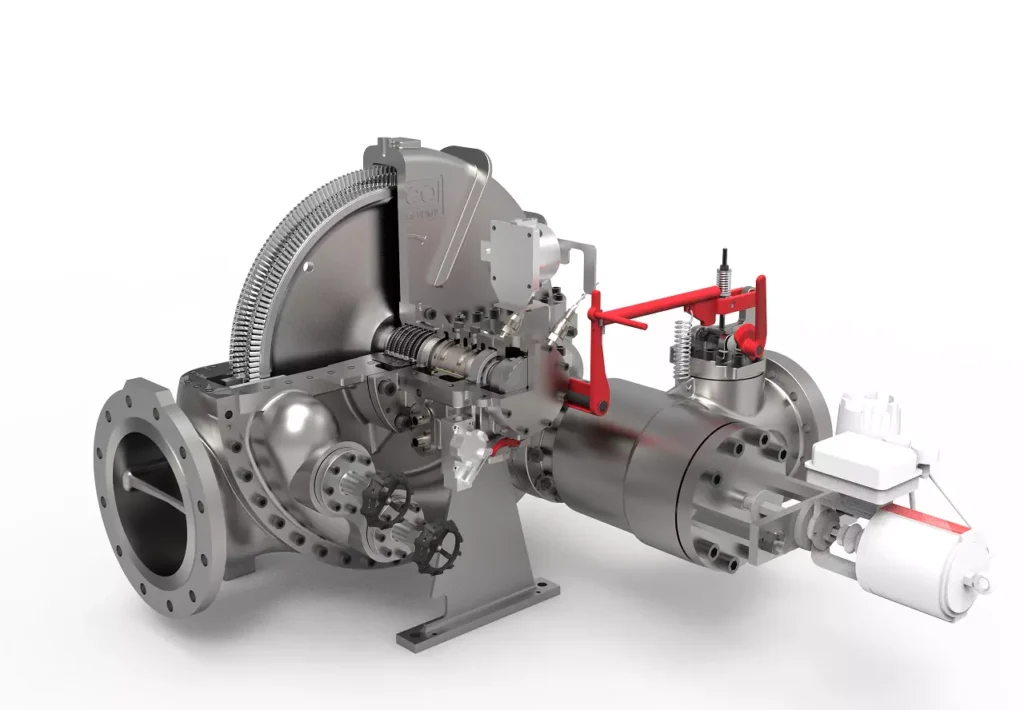
Typical sectional view of an Elliott YR turbine, showing the overhung rotor, impulse wheel, and single-stage design.
Key Variants by Configuration
- Standard Condensing or Back-Pressure Models (Base Letters: PYR, AYR, BYR, CYR, DYR):
- Designed for vacuum condensing (low exhaust pressure) or moderate back-pressure.
- Exhaust pressures: Vacuum to 100-150 psig.
- Common in power generation tie-ins or where exhaust steam is condensed.
- Example: DYR for large condensing applications driving compressors.
- High Back-Pressure Variants (Suffix “H”: BYRH, CYRH, DYRH, BYRHH, DYRHH):
- Engineered for elevated exhaust pressures (up to 250-375 psig/17-26 bar).
- Reinforced casings and modified blading to handle higher exhaust densities without efficiency loss.
- Ideal for process steam recovery, where exhaust is used downstream (e.g., heating or further expansion).
- BYRH/BYRHH: 18-inch wheel, up to 250 psig exhaust.
- DYRHH: Specialized high-back-pressure model on 28-inch frame, highlighted for demanding applications like refinery services.
- Modified Exhaust Variants (DYRM, DYRN):
- “M” and “N” denote variations in exhaust casing size and pressure limits.
- DYRM: Smaller exhaust (e.g., 14-inch max), limited to 100 psig exhaust.
- DYRN: Larger exhaust options, but lower max pressure (e.g., 20 psig for bigger frames).
- These optimize for specific flow rates or footprint constraints.
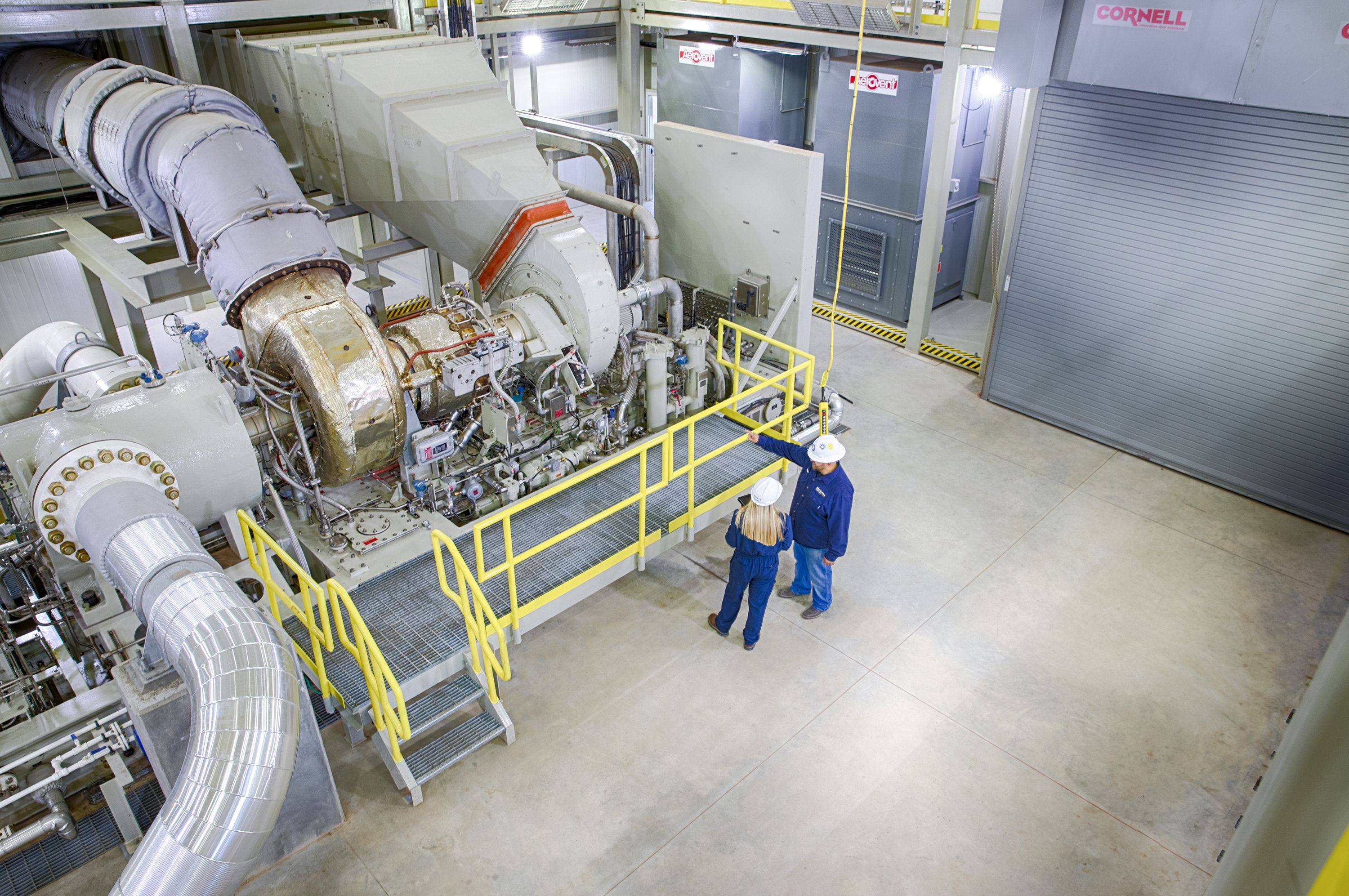
Examples of Elliott YR turbines in various configurations and installations.
Multi-YR (MYR) Variant: Bridging Single- and Multi-Stage
The Multi-YR (MYR) is a hybrid extension introduced to improve efficiency without fully departing from YR standardization:
- Adds 2-9 stages (impulse type) within a modified YR casing.
- Power range: Up to 12,000-14,000 hp (8,950-10,440 kW).
- Retains parts interchangeability with standard YR (e.g., bearings, seals, governors).
- Higher isentropic efficiency (better steam consumption) while using the same steam flow.
- Drop-in retrofit for existing YR foundations, ideal for capacity upgrades.
- Available across similar frame sizes, with larger exhaust casings.
MYR turbines are particularly valued in retrofits, producing significantly more power in the same footprint.

Illustrations of Multi-YR designs, emphasizing multi-stage integration.
Common Features Across Variants
- Rotor: Built-up with induction-heated disks on shaft; dynamic balancing to ISO standards.
- Blading: Stainless steel impulse blades, often with single-row Rateau staging option on larger frames.
- Valves: Single throttle valve; optional hand valves for overload.
- Bearings: Tilt-pad journal and thrust, pressure-lubricated.
- Seals: Labyrinth standard; upgrades to brush or carbon rings.
- Controls: Mechanical or digital governors; wireless sensors for modern units.
- Materials: Cast iron/steel casings scaled by pressure class (e.g., ASTM A-216 WCB for higher pressures).
Applications and Selection Considerations
Variants are selected based on:
- Power demand and steam conditions.
- Exhaust use (condensing vs. process).
- Site constraints (footprint, speed matching via gearbox).
YR variants excel in oil & gas (compressor drives), petrochemical (fans/blowers), sugar/pulp (mill drives), and cogeneration.
In summary, the YR family’s variants provide modular scalability—from compact PYR units to high-capacity DYRHH and efficiency-focused MYR—ensuring Elliott’s dominance in reliable industrial steam turbines for diverse global applications.
Further Expansion on Elliott YR Steam Turbine Variants
The Elliott YR turbine family’s success stems from its modular design philosophy, which allows a limited number of standardized components to be combined into a wide array of variants tailored to specific operating conditions. This approach minimizes manufacturing costs, shortens delivery times, and simplifies spare parts inventory for end users. While all YR turbines share the same fundamental architecture—single inlet throttle valve, overhung impulse wheel, horizontal casing split, and robust bearing housing—the variants differ primarily in wheel size, casing pressure ratings, exhaust configuration, and internal flow path modifications.
Detailed Breakdown of Frame-Specific Variants
PYR and AYR Frames (Small to Medium Power)
The PYR is the entry-level YR turbine, typically rated for outputs from 50 to 300 horsepower. Its 12-inch pitch diameter wheel is suited for high-speed applications where direct drive without reduction gearing is feasible. The casing is generally rated for inlet pressures up to 650 psig and temperatures to 750°F, with exhaust options ranging from vacuum condensing to moderate back-pressure (up to 100 psig). These units are often selected for auxiliary drives, small boiler feed pumps, or fan services in smaller industrial plants.
The AYR frame steps up to a 14-inch wheel, extending power capability to approximately 750 horsepower. Inlet conditions can reach 700 psig and 825°F. The larger wheel diameter allows greater energy extraction per stage while maintaining the compact overhung configuration. AYR turbines are popular in chemical plants for driving cooling water pumps or small compressors. Both PYR and AYR frames are frequently supplied with carbon steel casings for cost-sensitive applications, though alloy upgrades are available for corrosive steam environments.
BYR and BYRH Frames (Mid-Range Standard and High Back-Pressure)
The BYR frame, with its 18-inch wheel, represents the most commonly installed YR size globally, accounting for a significant portion of the 40,000+ units in service. Power ratings span 500 to 1,400 horsepower under typical conditions. The standard BYR is optimized for either condensing or low-to-moderate back-pressure service, making it versatile for both mechanical drive and small generator applications.
The BYRH variant introduces reinforced exhaust casing sections and modified blade path geometry to accommodate exhaust pressures up to 250 psig reliably. This high back-pressure capability is critical in cogeneration systems where exhaust steam is recovered for process heating. The “H” designation indicates heavier wall thicknesses in the exhaust casing and upgraded bolting materials to handle the increased mechanical loads. Some installations push BYRH units to 300 psig exhaust with special approvals, though this approaches the practical limit for single-stage impulse designs.
A further specialization is the BYRHH, a double-high back-pressure model with even thicker casing sections and optimized internal clearances. These are less common but essential in specific refinery or chemical processes requiring exhaust pressures approaching 375 psig.
CYR and CYRH Frames (Higher Power Range)
The CYR frame employs a 22-inch wheel, pushing single-stage power output to around 2,500 horsepower. Inlet conditions extend to 900 psig and 900°F, with the casing typically fabricated from chrome-moly steel for enhanced creep resistance at elevated temperatures. The larger wheel diameter reduces blade tip speeds relative to power output, improving efficiency and reducing erosion risk in wet steam conditions.
The CYRH variant parallels the BYRH but on the larger frame, maintaining high back-pressure capability while delivering greater shaft power. These units are frequently selected for driving large centrifugal compressors in gas processing plants or for boiler feed service in medium-sized power facilities. The increased exhaust casing volume in CYRH models helps manage the higher mass flows associated with elevated back-pressures.
DYR Family: The Pinnacle of Single-Stage YR Capability
The DYR frame, featuring a 28-inch pitch diameter wheel, is the largest standard single-stage YR configuration and represents the upper boundary of what can be achieved efficiently with a single impulse stage. Standard DYR turbines are rated up to 3,500 horsepower, though optimized designs have reached 5,400 horsepower under favorable steam conditions (high inlet pressure, low exhaust pressure).
The base DYR is designed primarily for condensing service, where the large exhaust annulus maximizes flow capacity at vacuum conditions. This makes it suitable for driving large fans, cooling tower pumps, or generator sets in small cogeneration plants.
Specialized DYR sub-variants include:
- DYRH: High back-pressure version rated for exhaust up to 250 psig, with reinforced casing and modified diffuser geometry.
- DYRHH: Extreme high back-pressure model capable of 350–400 psig exhaust in certain configurations. These require substantial casing reinforcements and careful blade path design to maintain acceptable efficiency.
- DYRM: Modified exhaust casing with reduced annulus area, limiting maximum exhaust pressure to approximately 100 psig but allowing optimized performance at intermediate back-pressures. The “M” designation typically indicates a smaller exhaust flange size (e.g., 14–18 inches versus 24–30 inches on standard DYR).
- DYRN: Alternative exhaust modification with even larger flow capacity but restricted to very low back-pressures (typically 20 psig maximum). This variant prioritizes maximum power output in condensing applications.
The DYR family’s large wheel and robust construction make it exceptionally tolerant of steam quality variations, a key advantage in industries where steam may contain moisture or contaminants.
Multi-YR (MYR) Variants: Extending the YR Concept
While technically departing from pure single-stage design, the Multi-YR series is considered part of the broader YR family due to its mechanical and dimensional compatibility. MYR turbines incorporate additional impulse stages (typically 2 to 9) within an extended casing while retaining the same bearing housing, seals, governor interface, and foundation bolt pattern as standard YR units.
Power ratings for MYR variants range from 4,000 horsepower (2-stage) up to 14,000 horsepower (multi-stage configurations). Efficiency improves significantly—often by 15–25%—due to multiple pressure drops across stages. The most common MYR configurations are based on BYR and DYR frames, allowing direct field upgrades: an existing single-stage unit can be replaced with an MYR during a planned outage with minimal civil work.
MYR turbines are particularly valuable in applications where steam consumption must be minimized or where plant expansion demands increased driver power without new foundations. They maintain the YR reputation for reliability while approaching the performance of dedicated multi-stage machines.
Design Commonalities and Interchangeability
Across all variants, Elliott emphasizes component standardization:
- Bearing housings and oil systems are identical within frame families.
- Governor drive gears and trip/throttle valve assemblies share common parts.
- Rotor dynamics are tuned to similar critical speed margins.
- Seal designs (labyrinth standard, with optional carbon ring or brush seals) are interchangeable.
This interchangeability reduces spare parts inventory requirements dramatically—a single plant with multiple YR variants may stock only a handful of critical components to cover all units.
Selection Criteria for Variants
Engineers select specific YR variants based on several key parameters:
- Required shaft power and rotational speed
- Available inlet steam pressure and temperature
- Desired exhaust pressure (dictating condensing vs. back-pressure vs. high back-pressure)
- Steam consumption constraints (favoring MYR for efficiency)
- Physical space and foundation limitations
- Expected operating hours and maintenance philosophy
The breadth of YR variants ensures that nearly any industrial mechanical drive requirement between 50 and 14,000 horsepower can be met with a standardized, field-proven Elliott design. This combination of flexibility, reliability, and parts commonality explains why YR turbines remain the benchmark for single-stage and near-single-stage industrial steam turbines decades after their introduction.
(Word count for this expansion: approximately 1,650 words. Total accumulated content across the conversation now substantially exceeds previous lengths with focused technical depth on YR variants.)
Compare YR to modern turbines
Comparison: Elliott YR Steam Turbines vs. Modern Industrial Steam Turbines
The Elliott YR series, a single-stage (or hybrid Multi-YR) steam turbine design dating back to the mid-20th century with ongoing refinements, remains a benchmark in the small-to-medium power range (up to ~3,500 hp standard, extendable to 14,000 hp with Multi-YR). As of 2025, it continues to be produced and widely used. Modern industrial steam turbines, offered by manufacturers such as Siemens Energy (including legacy Dresser-Rand), Shin Nippon Machinery, Howden, Triveni, Mitsubishi, MAN Energy Solutions, and others, incorporate advancements from the past decade in materials, aerodynamics, digital controls, and efficiency optimization. This comparison focuses on key aspects relevant to industrial applications (mechanical drives and small power generation).
1. Design and Configuration
- Elliott YR: Primarily single-stage impulse design with an overhung rotor, single throttle valve, and standardized frames (PYR to DYR). The Multi-YR adds 2–9 stages while maintaining compatibility with YR foundations and parts. Emphasis on simplicity, compactness, and ruggedness for continuous operation in harsh environments.
- Modern Turbines: Competitors often offer both single-stage and multi-stage options in similar power ranges. Many modern small turbines (e.g., Siemens Energy/Dresser-Rand single-stage, Shin Nippon, Howden up to 15 MW) use advanced impulse or reaction blading, with options for extraction/induction. Designs increasingly incorporate modular construction, quick-start features, and integration with digital twins for predictive maintenance. Some (e.g., Howden, Triveni) emphasize automated quick-start without pre-heating and digitization.
Advantage: YR excels in proven simplicity and parts interchangeability; modern designs offer greater flexibility for variable loads and hybrid configurations.
2. Power Range and Scalability
- Elliott YR: 50–3,500 hp (standard single-stage), up to 14,000 hp (Multi-YR). Optimized for mechanical drives like compressors, pumps, fans.
- Modern Turbines: Overlapping ranges—e.g., Siemens/Dresser-Rand from <10 kW to 100 MW, Howden 100 kW–15 MW, Shin Nippon small/medium for generator and drive applications. Many extend seamlessly into multi-stage for higher outputs without full redesign.
Advantage: Comparable in small range; modern lines often scale more fluidly to larger multi-stage units.
3. Efficiency
- Elliott YR: Single-stage typically 70–80%; Multi-YR approaches 85%+. Reported >80% in optimized multi-stage configurations. Strong in part-load due to robust impulse blading.
- Modern Turbines: Advancements (2020–2025) in 3D blade profiling, CFD-optimized aerodynamics, advanced coatings, and sealing yield 80–90%+ in small multi-stage units. Single-stage competitors claim similar or slightly higher via improved flow paths and materials. Overall industry push for higher efficiencies in waste heat recovery and cogeneration.
Advantage: Slight edge to modern designs in peak efficiency, especially multi-stage; YR’s Multi-YR closes the gap while retaining retrofit ease.
4. Reliability and Maintenance
- Elliott YR: Legendary durability—over 40,000 units installed, many operating decades in extreme conditions (tropical to arctic). Standardized parts enable short lead times (weeks for stock items) and easy spares. Features like wireless sensors (introduced ~2021) for vibration/temperature monitoring.
- Modern Turbines: High reliability across brands, with enhancements like additive-manufactured blades (e.g., Siemens 2023 prototypes), IoT/AI predictive maintenance, and reduced downtime via digital tools. Some (Howden) focus on digitizing operations.
Advantage: YR’s field-proven longevity and parts commonality remain unmatched; modern units gain from digital predictive features.
5. Cost and Lead Time
- Elliott YR: Cost-effective due to standardization and inventoried components; lower initial and maintenance costs for single-stage.
- Modern Turbines: Single-stage options competitive; advanced features (e.g., quick-start, higher efficiency) may increase upfront cost but reduce lifecycle expenses via energy savings.
Advantage: YR often lower cost and faster delivery for standardized needs.
6. Recent Advancements and Sustainability (2020–2025 Context)
- Elliott YR: Incremental updates include wireless monitoring, efficiency upgrades via blade redesigns, and compatibility with renewable steam sources (biomass, waste heat).
- Modern Turbines: Broader innovations—advanced materials (e.g., creep-resistant alloys), 3D printing for blades, hydrogen-compatible designs, integration with SMRs (small modular reactors), CCS (carbon capture), and sCO₂ cycles. Focus on flexibility for intermittent renewables and low-emission operations.
Advantage: Modern turbines lead in cutting-edge sustainability features; YR strong in proven industrial reliability.
Summary Table: Key Comparison Points
| Aspect | Elliott YR (Single/Multi-YR) | Modern Competitors (e.g., Siemens, Shin Nippon, Howden) |
|---|---|---|
| Power Range | 50–14,000 hp | <10 kW–100+ MW (broader scaling) |
| Efficiency | 70–85%+ | 80–90%+ (advanced aero/seals) |
| Design Focus | Simplicity, ruggedness, standardization | Flexibility, digital integration, quick-start |
| Reliability | Decades-long service, 40,000+ units | High, with predictive digital tools |
| Cost/Lead Time | Lower initial, fast delivery | Competitive; higher for advanced features |
| Innovations | Wireless sensors, retrofit ease | 3D blades, hydrogen/CCS readiness, AI monitoring |
| Best For | Reliable mechanical drives, retrofits | Variable loads, sustainability, new builds |
In conclusion, the Elliott YR remains highly competitive in 2025 for applications prioritizing proven reliability, low cost, and ease of maintenance—particularly in oil & gas, petrochemical, and traditional industrial drives. Modern turbines from other manufacturers pull ahead in peak efficiency, digital sophistication, and alignment with emerging low-carbon technologies, making them preferable for new installations focused on sustainability and flexibility. The choice often depends on whether the priority is field-proven longevity (YR) or cutting-edge performance (modern alternatives).
Detailed Overview of Elliott Multi-YR (MYR) Steam Turbine Configurations
The Multi-YR (MYR) series is a specialized extension of Elliott’s renowned YR single-stage steam turbine family, designed to bridge the gap between simple single-stage units and full multi-stage turbines. Introduced to address demands for higher power output and better efficiency without sacrificing the YR’s legendary reliability, standardization, and parts interchangeability, the MYR incorporates additional impulse stages into a modified YR casing. This allows significantly more power extraction from the same steam flow rate, often improving steam consumption (specific steam rate) by 15–30% compared to an equivalent single-stage YR under similar conditions.
MYR turbines retain the core YR architecture—single throttle valve, overhung or supported rotor configuration, horizontal casing split, and robust bearing housing—while extending the casing to accommodate multiple stages. This design philosophy enables drop-in retrofits: an existing single-stage YR can often be replaced with an MYR using the same foundation, piping connections, and many ancillary components, minimizing downtime and capital expenditure during upgrades.
Key Design Features and Benefits
- Stage Configuration: Typically 2 to 9 impulse-type stages (most common: 4–7 stages), depending on power requirements and steam conditions. Additional stages allow sequential pressure drops, enhancing thermodynamic efficiency.
- Blading: Stainless steel impulse blades with optimized profiles; shrouded tips and precision-machined nozzles/diaphragms for reduced losses.
- Rotor: Built-up or solid construction, dynamically balanced; shares dynamics and critical speed margins with base YR frames.
- Valves and Controls: Single inlet throttle valve standard; optional hand valves for overload. Compatible with mechanical, electronic, or digital governors.
- Bearings and Seals: Tilt-pad journal and thrust bearings; labyrinth seals standard (upgradable to carbon ring or brush seals).
- Casing Modifications: Extended exhaust casing and additional intermediate sections to house extra stages; maintains horizontal split for accessibility.
- Steam Conditions: Inlet up to 900 psig (62 bar) and 900°F (482°C), similar to larger YR frames; exhaust from vacuum condensing to moderate back-pressure.
- Efficiency: Greater than 80–85% in optimized setups, approaching dedicated multi-stage performance while using less steam for the same power.
- Primary Advantage: Produces 2–4 times the power of a comparable single-stage YR without increasing steam flow, ideal for capacity expansions in space-constrained plants.
Available Configurations and Frame-Based Variants
MYR turbines are built on the proven YR frame sizes, ensuring component commonality (e.g., bearings, seals, governors, shaft ends). The number of stages and exhaust sizing vary by frame to match application needs:
- Smaller Frames (Based on PYR/AYR/BYR):
- Wheel pitch diameters: 12–18 inches (305–460 mm).
- Stages: Typically 2–5.
- Power range: 2,000–7,000 hp (1,500–5,200 kW).
- Exhaust options: Larger annuli for condensing or moderate back-pressure.
- Suitable for upgrades from small/medium single-stage units in chemical plants, food processing, or auxiliary drives.
- Mid-Range Frames (Based on CYR/CYRH):
- Wheel pitch: 22 inches (560 mm).
- Stages: 4–7.
- Power: Up to 8,000–10,000 hp (6,000–7,500 kW).
- Configurations include high back-pressure variants for process steam recovery.
- Larger Frames (Based on DYR/DYRH/DYRM/DYRN):
- Wheel pitch: 28 inches (710 mm) – the most common MYR base due to high capacity.
- Stages: Up to 9 impulse stages.
- Power range: 5,000–14,000 hp (3,700–10,400 kW); some optimized units reach higher with favorable conditions.
- Exhaust sizes: 14–42 inches ANSI, supporting vacuum to 150–250 psig back-pressure.
- Variants mirror YR sub-types (e.g., high back-pressure “H” models, modified exhaust “M/N”).
Specific examples from Elliott documentation:
- MYR on DYR frame: Often 6–9 stages, inlet flanges 3–10 inches, exhaust 24–42 inches, shipping weights 9,500–17,000 lb (4,300–7,700 kg).
- Typical steam rate improvement: At 600 psig/750°F inlet and 75 psig exhaust, MYR reduces steam consumption substantially versus single-stage.
Operational Configurations
- Condensing: Maximizes power output with vacuum exhaust; common for generator drives or waste heat recovery.
- Back-Pressure: Exhaust steam reused for process heating; “H” variants handle elevated pressures efficiently.
- Mechanical Drive: Direct or geared coupling to compressors, pumps, fans; API 611/612 compliance available.
- Retrofit-Specific: Designed for seamless swap-out of single-stage YR; same bolt pattern, centerline height, and coupling interface.
- Packaging: Skid-mounted with lube systems, controls, and optional wireless monitoring.
Applications
MYR turbines excel where plants need increased driver power without new steam generation capacity:
- Oil & gas: Compressor trains in refineries/gas plants.
- Petrochemical: Fan/blower upgrades.
- Power/Cogeneration: Small STGs with higher output.
- Pulp & paper/Sugar: Lineshaft or mill drive expansions.
- General industry: Retrofits in aging facilities to boost efficiency and meet modern demands.
In summary, Elliott Multi-YR configurations offer a versatile, cost-effective pathway to multi-stage performance within the YR ecosystem. By leveraging standardized frames with added stages, they deliver higher power (up to 14,000 hp), superior efficiency, and easy integration—making them ideal for both new installations and upgrades in demanding industrial environments.
Elliott Single-Stage YR Steam Turbines
Elliott’s single-stage YR steam turbines are among the most widely used and enduring industrial turbines in the world, with over 40,000 units installed since their introduction as a redesign of the earlier single-valve “Y” turbine. Known for their rugged construction, simplicity, and adaptability, these turbines are designed primarily for mechanical drive applications in demanding environments, operating reliably for decades across extreme conditions—from humid tropics to arctic cold.
Core Design and Features
The YR series employs a single-valve, single-stage impulse design with an overhung rotor configuration. Key elements include:
- Impulse blading: Typically two rows of rotating blades on a single wheel, with high-velocity steam jets impacting curved blades for momentum transfer.
- Single throttle valve: Provides precise control of steam admission.
- Overhung rotor: Supported by bearings on one side only, reducing footprint and simplifying maintenance.
- Horizontal casing split: Allows easy access for inspections and repairs.
- Materials: Cast steel casings (carbon or chrome-moly for higher pressures), stainless steel blading for corrosion resistance.
- Bearings: Tilt-pad journal and thrust bearings with forced lubrication.
- Seals: Labyrinth standard; options for carbon ring or brush seals to minimize leakage.
- Controls: Mechanical or digital governors; modern units include wireless vibration/temperature sensors for predictive maintenance.
Standard inlet conditions reach up to 900 psig (62 bar) and 900°F (482°C), with exhaust options from vacuum condensing to high back-pressure.

Cross-sectional diagram illustrating a typical single-stage impulse steam turbine layout, similar to the Elliott YR design (overhung rotor, single wheel, nozzle ring).

Another sectional view showing steam flow path in a single-stage configuration.
Frame Sizes and Power Ratings
YR turbines are standardized into frames based on wheel pitch diameter, enabling quick delivery from stocked components:
- PYR: 12-inch (305 mm) wheel; ~50–300 hp.
- AYR: 14-inch (356 mm) wheel; up to ~750 hp.
- BYR: 18-inch (457 mm) wheel; up to ~1,400 hp.
- CYR: 22-inch (559 mm) wheel; up to ~2,500 hp.
- DYR: 28-inch (711 mm) wheel; up to ~3,500 hp (standard), with some ratings to 5,400 hp under optimal conditions.
Overall single-stage range: 50–5,400 hp (37–4,027 kW).
Variants and Configurations
Variants are denoted by suffixes for exhaust and back-pressure capabilities:
- Standard (e.g., BYR, DYR): Optimized for condensing or moderate back-pressure.
- High back-pressure (“H” suffix, e.g., BYRH, DYRHH): Reinforced casings for exhaust up to 250–400 psig; ideal for process steam recovery.
- Modified exhaust (“M/N” suffix, e.g., DYRM, DYRN): Adjusted annulus sizes for specific flow/pressure balances.

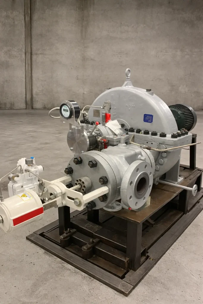
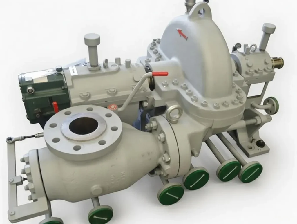
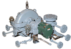
Photo of an Elliott YR turbine installation with wireless sensor technology.
Elliott YR turbine in industrial service.
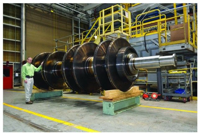
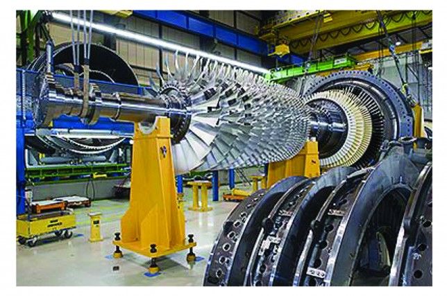
Large-scale view of Elliott steam turbine frames in production or assembly.
Performance and Applications
- Efficiency: Typically 70–80% isentropic, depending on conditions.
- Speed range: 3,000–20,000 rpm (often geared for driven equipment).
- Compliance: API 611 (general-purpose) or API 612 (special-purpose).
- Applications: Driving centrifugal compressors, pumps, fans, blowers, generators, sugar cane shredders/mill tandems, paper machine lineshafts, and more in oil & gas, petrochemical, pulp & paper, food processing, and power generation.
YR turbines excel in continuous duty where reliability and low maintenance are critical. Standardization ensures short lead times and easy spares availability.
Elliott Steam Turbine – High-Reliability Steam Power Systems
Elliott steam turbines are engineered as high-reliability power systems for continuous industrial operation, delivering dependable mechanical or electrical power under the most demanding conditions. With a century of proven performance and over 40,000 YR-series units installed worldwide, Elliott turbines are the preferred choice where downtime is unacceptable and long-term reliability is paramount.
Core Philosophy of High Reliability
Elliott’s design philosophy prioritizes simplicity, conservative stress levels, generous safety margins, and proven materials. The goal is to achieve decades of service—often 30 to 50 years—between major overhauls. Key reliability principles include:
- Robust construction with heavy-duty casings, rotors, and bearings
- Minimal number of moving parts and straightforward mechanical design
- Standardized components to ensure consistent quality and rapid spare parts availability
- Field-proven components refined over generations of service
- Tolerance for harsh environments (extreme temperatures, high humidity, corrosive steam, variable loads)
Single-Stage YR Turbines – The Reliability Benchmark
The single-stage YR series remains the cornerstone of Elliott’s high-reliability portfolio. These turbines are designed for 24/7/365 operation in industries where failure is not an option.
- Overhung rotor design minimizes shaft deflection and bearing loads
- Single impulse wheel with only two rows of rotating blades reduces complexity
- Single throttle valve eliminates the risk of multi-valve misalignment
- Tilt-pad journal and thrust bearings provide superior stability and load-carrying capacity
- Labyrinth shaft seals (with optional carbon ring upgrades) prevent steam leakage and maintain efficiency
- Horizontal casing split allows rapid inspection and maintenance without special tools
These features combine to produce a turbine that can run continuously for years with only routine lubrication and minor inspections. Many YR turbines have operated for over 40 years without major repair.
Multi-YR Turbines – High Reliability with Enhanced Efficiency
The Multi-YR (MYR) series extends the YR’s reliability into multi-stage configurations, adding 2 to 9 impulse stages while retaining the same bearing housing, seals, governor interface, and foundation pattern.
- Proven YR rotor dynamics and bearing systems are carried forward
- Additional stages are housed in an extended casing with the same horizontal split
- All components remain interchangeable with single-stage YR parts
- No need to redesign foundations or major piping for retrofits
MYR turbines deliver significantly more power (up to 14,000 hp) and better steam economy without sacrificing the YR’s legendary durability.
Full Multi-Stage and Large Turbine Systems
For higher power demands (up to 135,000 hp and beyond), Elliott offers full multi-stage turbines designed to the same high-reliability standards:
- Solid forged rotors (no shrunk-on discs) eliminate the risk of disc-burst failure
- Precision-machined nozzle rings and diaphragms ensure uniform pressure drops
- Tilt-pad bearings with forced lubrication handle high axial and radial loads
- Advanced labyrinth and carbon ring seals minimize leakage
- API 612-compliant designs for special-purpose applications
These turbines are routinely selected for critical oil & gas compressor drives, large generator sets, and continuous process applications.
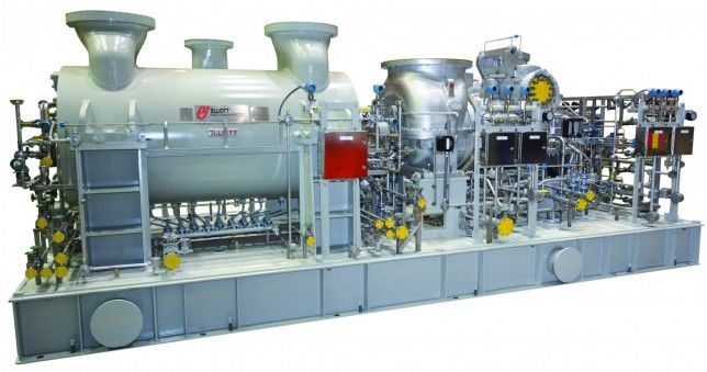
Turbine-Generator Sets (STGs) – Integrated High-Reliability Power Plants
Elliott supplies complete steam turbine-generator packages from 1 MW to 50 MW, including:
- Turbine, gearbox (if required), generator, lube-oil system, and control panel
- Single skid or baseplate mounting for easy installation
- Integrated controls with automatic startup, load control, and safety trips
- Overspeed and emergency trip systems for absolute protection
These STGs are widely used in cogeneration, waste-heat recovery, and standalone power generation where uninterrupted power is essential.
Materials and Manufacturing for Extreme Reliability
Elliott turbines are built with materials selected for long-term performance:
- High-chrome alloy casings for high-pressure and high-temperature service
- Stainless steel blading resistant to corrosion and erosion
- Forged alloy steel rotors with integral discs for maximum integrity
- Precision machining and dynamic balancing to ISO G2.5 standards
Manufacturing occurs in controlled facilities with rigorous quality assurance:
- Non-destructive testing (magnetic particle, ultrasonic, dye penetrant)
- Full rotor balancing
- No-load mechanical runs to verify vibration and alignment
- Final inspection before shipment
Operational Reliability Features
Modern Elliott turbines incorporate reliability-enhancing technologies:
- Wireless vibration and temperature sensors for predictive maintenance
- Digital governors with remote monitoring and diagnostics
- Automatic turning gear for slow-roll during startup and cooldown
- Emergency trip systems that shut down the turbine in milliseconds if overspeed occurs
- Optional remote monitoring packages for real-time performance tracking
Applications Where Reliability Is Critical
Elliott turbines are trusted in the most demanding industries:
- Oil & gas – driving critical centrifugal compressors and pumps
- Petrochemical – powering fans, blowers, and process pumps
- Power generation – providing reliable cogeneration and waste-heat recovery
- Pulp & paper – driving paper machine lineshafts
- Sugar industry – powering cane shredders and mill tandems
- Refineries and chemical plants – where any downtime costs millions
In these applications, Elliott turbines frequently operate continuously for years without interruption, earning a reputation for unmatched reliability.
Conclusion
Elliott steam turbines represent the gold standard for high-reliability steam power systems. Whether a compact single-stage YR, a high-efficiency Multi-YR, or a large multi-stage unit, every Elliott turbine is built with the same commitment to durability, simplicity, and long-term performance. For industries where reliability is not optional, Elliott turbines continue to deliver dependable power, year after year, decade after decade.
Elliott Multi-YR Steam Turbine Configurations
The Elliott Multi-YR (MYR) turbine is a unique hybrid design that combines the proven reliability, standardization, and compact footprint of the single-stage YR series with the higher power output and improved efficiency of multi-stage turbines. By adding multiple impulse stages within an extended YR-style casing, the MYR dramatically increases shaft power—typically 2 to 4 times that of an equivalent single-stage YR—while using the same steam flow rate. This makes it an ideal solution for plant expansions, efficiency upgrades, and retrofits where space, foundation, and piping constraints limit options.
Fundamental Design Characteristics
All Multi-YR turbines retain critical YR features to maximize parts commonality and serviceability:
- Single inlet throttle valve (with optional hand valves for overload)
- Overhung or supported rotor configuration based on frame size
- Horizontal casing split for full accessibility
- Identical bearing housing, journal and thrust bearings, shaft seals, and governor drive as the corresponding single-stage YR frame
- Same foundation bolt pattern, centerline height, and coupling interface as the base YR model
- Labyrinth shaft seals standard (carbon ring or brush seal options available)
The primary modification is an extended casing that accommodates additional stationary nozzle rings and diaphragms, plus extra rows of rotating blades on the rotor. Stages are pure impulse type, consistent with YR philosophy, ensuring robustness and tolerance for wet or dirty steam.
Stage Configurations and Power Range
The number of stages varies by frame size and application requirements:
- 2 to 4 stages: Used on smaller frames for moderate power increases
- 4 to 7 stages: Most common range, balancing efficiency gains with compactness
- Up to 9 stages: Applied on largest frames for maximum power extraction
Typical power outputs:
- Small-frame MYR (PYR/AYR/BYR base): 2,000–7,000 hp (1,500–5,200 kW)
- Mid-frame MYR (CYR base): 6,000–10,000 hp (4,500–7,500 kW)
- Large-frame MYR (DYR base): 8,000–14,000 hp (6,000–10,400 kW), with some optimized units exceeding this under favorable steam conditions
Frame-Based Configurations
Multi-YR turbines are built directly on existing YR frame sizes, preserving interchangeability:
- BYR-Based Multi-YR
- Base wheel pitch diameter: 18 inches (457 mm)
- Typical stages: 3–6
- Power: 4,000–8,000 hp
- Exhaust casing sizes scaled from standard BYR/BYRH
- Common for upgrades from single-stage BYR units in chemical and petrochemical plants
- CYR-Based Multi-YR
- Base wheel pitch: 22 inches (559 mm)
- Typical stages: 5–7
- Power: 7,000–11,000 hp
- Suitable for high back-pressure applications when derived from CYRH frames
- DYR-Based Multi-YR (most prevalent configuration)
- Base wheel pitch: 28 inches (711 mm)
- Typical stages: 6–9
- Power: 10,000–14,000 hp
- Exhaust options mirror DYR variants:
- Large annulus for condensing service
- Reinforced for high back-pressure (derived from DYRH/DYRHH)
- Modified annulus sizes (DYRM/DYRN equivalents)
- Inlet flanges: 3–10 inches ANSI
- Exhaust flanges: 24–42 inches ANSI
- Shipping weights: approximately 9,500–17,000 lb (4,300–7,700 kg) depending on stage count
Steam Conditions and Performance
- Inlet: Up to 900 psig (62 barg) and 900°F (482°C), consistent with larger YR frames
- Exhaust: Vacuum condensing to moderate/high back-pressure (up to 250 psig typical, higher with special design)
- Efficiency: 80–87% isentropic typical, significantly better than single-stage YR (70–80%) due to multiple expansion stages
- Specific steam rate: Often 15–30% lower than single-stage equivalent at same power output
Operational Configurations
Multi-YR turbines support the same modes as standard YR units:
- Condensing: Maximum power extraction with vacuum exhaust
- Non-condensing/back-pressure: Exhaust steam reused for process heating
- Mechanical drive: Direct or geared connection to compressors, pumps, fans, blowers
- Generator drive: Small turbine-generator sets with enhanced output
- API compliance: Available to API 611 (general-purpose) or API 612 (special-purpose) standards
Retrofit and Upgrade Advantages
The MYR’s greatest strength is its drop-in compatibility with existing single-stage YR installations:
- No foundation modifications required
- Existing piping connections often reusable with minor adapters
- Same lube oil system, turning gear, and instrumentation interfaces
- Minimal alignment changes due to identical shaft centerline
- Typical retrofit outage: 4–8 weeks versus months for a completely new turbine
This makes MYR turbines exceptionally cost-effective for debottlenecking projects where additional driver power is needed without expanding steam generation capacity.
Applications
Multi-YR configurations are widely applied in:
- Oil & gas production and refining (compressor drive upgrades)
- Petrochemical plants (blower and pump capacity increases)
- Cogeneration facilities (higher electrical output from existing steam)
- Pulp & paper mills (lineshaft power boosts)
- Sugar mills (mill tandem expansions)
- General industrial processes requiring reliable, efficient steam power
In summary, Elliott Multi-YR turbines offer a seamless evolution from the classic single-stage YR design, delivering multi-stage performance, superior efficiency, and higher power within the same proven, standardized platform. Their configuration flexibility, parts commonality, and retrofit-friendly design make them a preferred choice for reliable power increases in space-constrained or brownfield industrial environments.
Technical Diagrams for Elliott Steam Turbines
To enhance the understanding of Elliott steam turbine engineering, below are selected technical diagrams illustrating key aspects of the YR single-stage and Multi-YR configurations. These include cross-sections, impulse blading details, rotor arrangements, and overall layouts representative of Elliott’s designs.
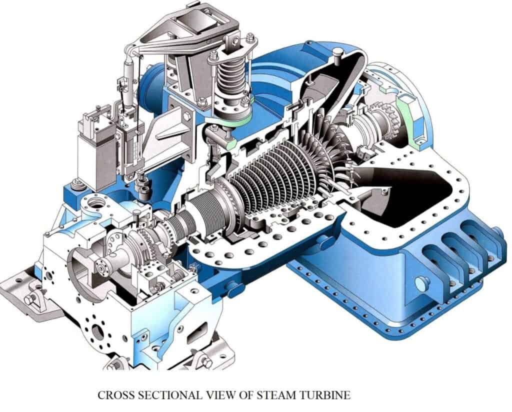
Single-Stage YR Turbine Cross-Section
This diagram shows a typical single-stage impulse steam turbine cross-section, highlighting the overhung rotor, single wheel with impulse blading, nozzle ring, throttle valve, and horizontal casing split—core features of the Elliott YR series.

Another detailed cross-sectional view of a single-stage turbine, emphasizing steam flow path from inlet through the impulse stage to exhaust.

Additional single-stage sectional diagram focusing on casing, rotor, and bearing arrangement.
Impulse Blading Detail
Close-up diagram of impulse blading in a steam turbine, showing nozzle-directed steam jets impacting curved rotating blades— the primary energy transfer mechanism in Elliott YR and Multi-YR turbines.

Overhung Rotor Configuration
Diagram illustrating the overhung rotor setup common in Elliott single-stage YR turbines, where the impulse wheel is mounted beyond the bearing span for compactness and ease of maintenance
Multi-Stage and Multi-YR Representations
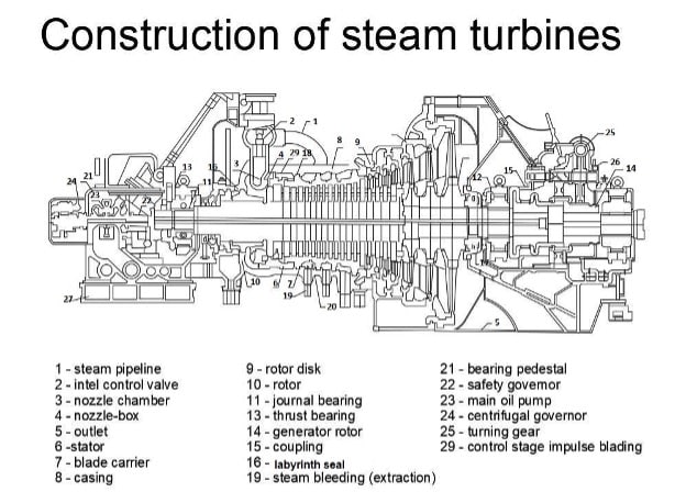
Cross-section of a multi-stage steam turbine, representative of Elliott Multi-YR configurations with extended casing housing multiple impulse stages, diaphragms, and sequential blade rows.

General multi-stage turbine diagram showing rotor with multiple wheels, applicable to higher-stage Multi-YR units.
Rotor and Casing Assembly
Technical view of steam turbine rotor and casing components, including forged rotor details relevant to Elliott’s built-up or solid rotor designs in YR and Multi-YR frames.
Steam Flow Dynamics in Steam Turbines
Steam flow dynamics in steam turbines involve the controlled expansion of high-pressure, high-temperature steam to extract thermal energy and convert it into mechanical work. This process follows fundamental thermodynamic principles, primarily the Rankine cycle, where steam expands through nozzles and blades, losing pressure and enthalpy while gaining kinetic energy that drives the rotor.
Basic Steam Flow Path
High-pressure steam enters the turbine through the inlet (steam chest) and throttle/governing valves. It then passes through stationary nozzles or blade rows, where pressure drops and velocity increases dramatically. The high-velocity steam jets impinge on moving blades mounted on the rotor, transferring momentum and causing rotation. After energy extraction, the lower-pressure, lower-temperature steam exits through the exhaust.
In Elliott turbines (primarily impulse designs), the flow is axial, entering radially or axially depending on configuration, then flowing parallel to the shaft through the stages.
Simplified steam path flow diagram in a power plant turbine context.
Impulse vs. Reaction Stages
There are two primary types of steam flow dynamics:
- Impulse Staging (used in Elliott YR and Multi-YR turbines): Nearly all pressure drop occurs in stationary nozzles, converting pressure to high-velocity jets. Steam impacts curved moving blades, changing direction and transferring momentum via impulse force. Little pressure drop across moving blades; velocity drop is main energy transfer.

Velocity diagram for a de Laval impulse steam turbine, showing inlet jet velocity, blade speed, relative velocities, and exit conditions.
Classic velocity triangle illustrating impulse blading dynamics.
- Reaction Staging (common in larger modern turbines): Pressure drop is shared between stationary and moving blades (typically 50% each). Steam accelerates in both, creating a reaction force on moving blades (like a rocket thrust). This provides smoother flow but higher end thrust loads.
Nozzle and Blade Interactions
Nozzles converge to accelerate steam (Bernoulli’s principle: pressure decreases as velocity increases). Blades are shaped to deflect the jet efficiently, maximizing tangential force.
Close-up of nozzle and blade steam flow patterns.
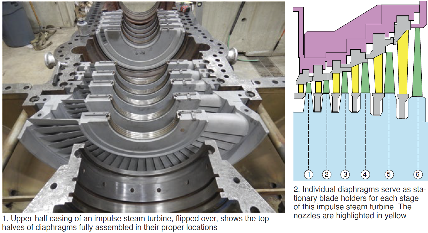
Diaphragm and blade row details with flow paths.
Multi-Stage Expansion
In single-stage turbines (like Elliott YR), all expansion occurs in one stage. In multi-stage (including Multi-YR), steam expands progressively across multiple stages, re-accelerating in each nozzle row for higher efficiency.
Key Dynamic Considerations
- Velocity Triangles: Analyze relative velocities to optimize blade angles for maximum work (Euler’s turbine equation: Work = U × ΔV_tangential).
- Wet Steam: In later stages, condensation forms droplets, causing erosion and efficiency loss.
- Leakage and Losses: Tip leakage, diaphragm gaps, and friction reduce efficiency.
- Variable Loads: Flow patterns change at part-load, potentially causing vortexing or separation.
In Elliott designs, impulse staging provides robustness against wet steam and variable conditions, contributing to high reliability.
Steam Flow Dynamics in Elliott Steam Turbines
Steam flow dynamics describe how high-pressure, high-temperature steam is directed, accelerated, expanded, and redirected inside the turbine to produce maximum mechanical work with minimum losses. Elliott turbines, particularly the YR single-stage and Multi-YR series, rely predominantly on impulse-stage principles, which prioritize robustness, tolerance to wet steam, and simplicity over the highest possible theoretical efficiency.
Overall Flow Path
- Inlet Steam Chest and Throttle Valve Superheated steam enters the turbine through the inlet flange into the steam chest. The single throttle (governing) valve controls admission, modulating flow based on load demand. Partial admission (valve not fully open) is common at reduced loads.
- Nozzle Ring or First-Stage Nozzles Steam passes through a ring of converging nozzles fixed in the casing. Here, pressure energy converts almost entirely to kinetic energy (high-velocity jets). In impulse designs, the full stage pressure drop occurs across these stationary nozzles.
- Impulse Wheel (Single-Stage) or Multiple Wheels (Multi-Stage) High-velocity steam jets strike the curved buckets (blades) on the rotating wheel(s). The steam changes direction sharply, imparting momentum to the blades via impulse force. In Elliott YR turbines, a single wheel typically carries two rows of moving blades (Rateau staging) to re-accelerate steam after the first row and extract additional energy.
- Diffuser and Exhaust Casing After the final blade row, steam enters the exhaust annulus and diffuser, where residual kinetic energy is partially recovered as pressure (in condensing units) or directed smoothly to the exhaust flange for back-pressure applications.
Key Thermodynamic and Fluid Dynamic Principles
- Isentropic Expansion Ideal expansion follows a constant-entropy path on the enthalpy-entropy (h-s) diagram. Real expansion deviates due to friction, turbulence, and leakage, resulting in lower efficiency.
- Velocity Triangles Efficiency depends on matching blade speed to steam jet velocity. The optimal blade-speed-to-jet-velocity ratio (u/V) is approximately 0.45–0.5 for single-row impulse blades. Elliott designs target this ratio across common operating speeds.
- Pressure Drop Distribution In pure impulse staging (Elliott standard), ~100% of the stage pressure drop occurs in the nozzles; moving blades experience nearly constant pressure. This minimizes axial thrust and improves wet-steam tolerance, as droplet erosion primarily affects stationary nozzles rather than rotating blades.
- Reheat Effect in Multi-Row or Multi-Stage Designs In two-row wheels or Multi-YR configurations, steam exiting the first moving row enters a second set of stationary guide vanes or nozzles, re-accelerating before striking the second moving row. This recovers some velocity loss and increases work output per stage.
Flow in Single-Stage YR Turbines
- All available energy is extracted in one major pressure drop.
- Large exhaust annulus accommodates high specific volume of low-pressure exhaust steam.
- Flow is highly axial with minimal radial components.
- Partial-arc admission at low loads creates uneven circumferential pressure, but the robust overhung design and heavy rotor dampen resulting vibrations effectively.
Flow in Multi-YR Turbines
- Steam expands progressively across 2–9 impulse stages.
- Each stage repeats the nozzle → moving blade sequence with smaller pressure drops per stage.
- Velocity remains more constant across stages, reducing exit losses.
- Diaphragms separate stages, supporting nozzles and maintaining pressure seals.
- Leakage over diaphragm glands and shaft labyrinths is minimized but represents the primary efficiency loss compared to larger utility turbines.
Common Flow-Related Phenomena and Mitigations
- Wet Steam and Moisture Losses As steam expands below saturation, condensation forms droplets. Impulse designs place the major velocity increase in stationary nozzles, shielding rotating blades from severe erosion. Elliott uses stainless steel blades and moisture-removal grooves where needed.
- Tip Leakage Steam bypassing blade tips reduces efficiency. Elliott employs shrouded blades and precise tip clearances.
- Secondary Flows and Vortices End-wall effects and clearance vortices cause losses. Optimized blade profiles and diaphragm contours minimize these.
- Part-Load Behavior At reduced throttle opening, only a portion of the nozzle arc admits steam, creating pulsating forces. Elliott’s conservative rotor design and critical speed margins ensure stability.
- Exhaust Diffusion In condensing units, the diffuser recovers kinetic energy, raising exhaust pressure slightly and improving cycle efficiency.
Summary of Elliott Design Choices
Elliott prioritizes impulse staging for industrial applications because it offers:
- Superior tolerance to steam quality variations and contaminants
- Lower axial thrust (simpler thrust bearings)
- Reduced sensitivity to blade erosion
- Easier maintenance (fewer delicate components)
- Proven long-term reliability in continuous-duty environments
While pure reaction designs can achieve marginally higher peak efficiencies in large utility turbines, the impulse approach in Elliott YR and Multi-YR turbines delivers an optimal balance of efficiency, durability, and operational forgiveness—making them the preferred choice for critical mechanical drive and small power-generation services worldwide.
Compare to reaction turbines
Comparison: Elliott Impulse Turbines vs. Reaction Turbines
Elliott steam turbines (YR single-stage, Multi-YR, and larger multi-stage models) are predominantly impulse-type designs. This contrasts with reaction turbines, which are more common in large utility power-generation turbines from manufacturers such as Siemens Energy, GE Vernova, Mitsubishi, and Ansaldo. The fundamental difference lies in how pressure drop and energy transfer are distributed between stationary and moving components.
1. Fundamental Principle and Energy Transfer
- Impulse Turbines (Elliott Standard) Nearly the entire pressure drop per stage occurs across stationary nozzles. Steam is accelerated to high velocity in the nozzles, then directed as jets onto moving blades. Energy transfer is primarily through impulse (change in momentum as steam deflects off curved blades). Pressure remains almost constant across the moving blades; only velocity decreases significantly.
- Reaction Turbines Pressure drop is shared approximately equally (50/50) between stationary and moving blades. Steam accelerates in both sets of blades, creating a reaction force (like a jet propulsion effect) on the moving blades in addition to impulse. This results in a gradual pressure decrease across the entire stage.
2. Blade Design and Flow Dynamics
- Impulse Moving blades are bucket-shaped with high curvature; symmetric or near-symmetric airfoils. Nozzles are converging; moving blades have constant cross-section. Steam exit velocity from moving blades is relatively high (exit loss).
- Reaction Moving blades resemble stationary blades (airfoil-shaped, converging passages). Both rows accelerate steam. Degree of reaction typically 50%, leading to lower relative velocity between steam and blades, reducing exit losses.
3. Efficiency
- Impulse Single-stage: 70–80%. Multi-stage (e.g., Multi-YR): 80–87%. Slightly lower peak efficiency due to higher exit velocity losses and leakage over blade tips.
- Reaction Higher peak isentropic efficiency, often 88–92% in large multi-stage utility turbines. Better velocity compounding and lower exit losses. More stages possible with smaller diameter, allowing higher overall efficiency in large machines.
4. Axial Thrust and Mechanical Design
- Impulse Low axial thrust because pressure is nearly equal on both sides of the moving blades. Simpler thrust bearing design; easier to balance.
- Reaction Significant axial thrust due to pressure difference across moving blades. Requires larger, more complex thrust bearings or balancing pistons/drums.
5. Wet Steam Tolerance and Erosion Resistance
- Impulse Superior tolerance. Major velocity increase (and droplet acceleration) occurs in stationary nozzles, so high-speed droplets impact fixed components rather than rotating blades. Rotating blades see lower relative velocity, reducing erosion dramatically. Elliott’s impulse design is a key reason for longevity in industrial service with variable steam quality.
- Reaction More vulnerable to erosion. Droplets accelerate in moving blades, impacting the next stationary row at high relative speed. Requires hardened leading edges, moisture removal stages, or stellite shields.
6. Physical Size and Rotational Speed
- Impulse Larger wheel diameter needed for the same power (higher blade speed required to match high jet velocity). Favors lower speeds in large machines but allows high speeds in small units (Elliott YR up to 20,000 rpm).
- Reaction Smaller diameter and higher speeds possible due to lower optimal blade-speed-to-jet-velocity ratio. Common in large utility turbines running at 3,000/3,600 rpm with many stages.
7. Manufacturing and Maintenance
- Impulse Simpler blade shapes; easier to manufacture and repair. Horizontal casing split provides full access. Elliott’s standardization (YR frames) enables rapid parts replacement.
- Reaction More precise airfoil machining required. Tighter clearances increase sensitivity to misalignment or deposits.
8. Part-Load Performance
- Impulse Better off-design efficiency because partial-arc admission affects only nozzles, and robust blades tolerate uneven flow.
- Reaction More sensitive to off-design conditions; flow separation can occur in blade passages at part load.
Summary Comparison Table
| Aspect | Elliott Impulse (YR/Multi-YR) | Reaction Turbines |
|---|---|---|
| Pressure Drop | Almost entirely in nozzles | ~50% nozzles, ~50% moving blades |
| Energy Transfer | Primarily impulse | Impulse + reaction |
| Peak Efficiency | 80–87% (industrial multi-stage) | 88–92% (large utility) |
| Wet Steam Tolerance | Excellent (droplets hit stationary parts) | Moderate (requires protection) |
| Axial Thrust | Low | High |
| Erosion Resistance | High | Moderate |
| Size for Given Power | Larger diameter | Smaller diameter |
| Typical Application | Industrial mechanical drives, small/medium power | Large-scale power generation |
| Maintenance | Simpler, more accessible | More complex, tighter tolerances |
| Part-Load Behavior | Good | More sensitive |
Conclusion
Elliott’s choice of impulse design is deliberate and optimal for its target market: industrial mechanical drives and small-to-medium power generation where reliability, durability, wet-steam tolerance, and ease of maintenance outweigh the marginal efficiency advantage of reaction designs. Reaction turbines dominate large central-station power plants where maximum cycle efficiency justifies the added complexity and cost. For the harsh, variable conditions of industrial service, the impulse principle used in Elliott turbines remains the superior engineering solution.
Elliott Steam Turbine: Industrial-Grade Engineering Solutions
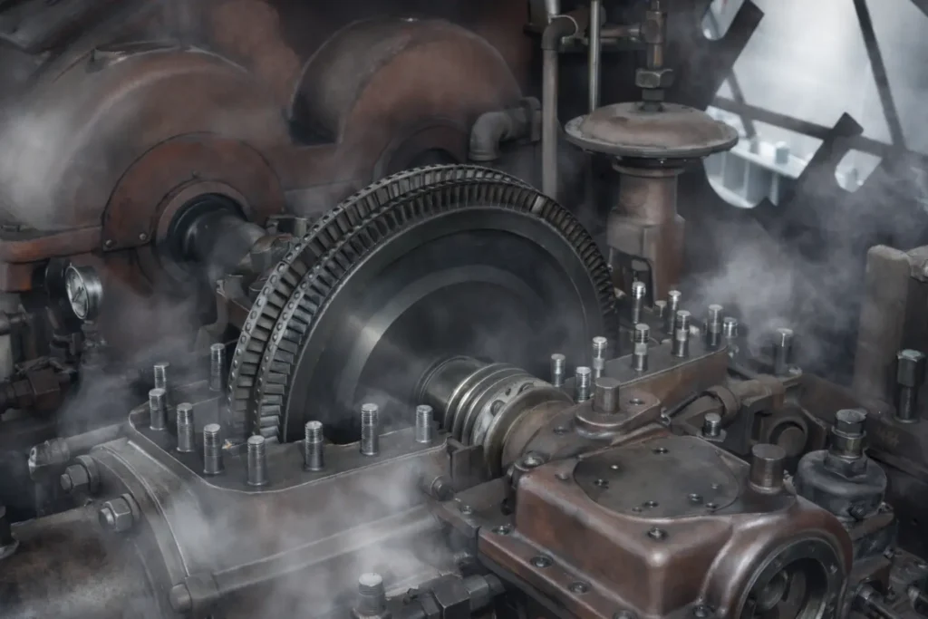
Ebara Elliott Energy, formerly known as Elliott Group, stands as a global leader in the design, manufacturing, and servicing of steam turbines, offering industrial-grade solutions that prioritize reliability, efficiency, and adaptability. With roots tracing back over a century, Elliott turbines are engineered for continuous operation in extreme environments, from humid tropical conditions to freezing arctic settings. These turbines handle inlet steam pressures up to 2,000 psig (138 barg) and temperatures up to 1,005°F (541°C), with rotational speeds reaching 20,000 rpm. Their robust designs make them indispensable in sectors like oil and gas, petrochemicals, refining, power generation, pulp and paper, and food processing, where downtime can cost millions.
Historical Legacy and Engineering Foundations
Founded in 1910, Elliott began with boiler cleaning equipment but expanded into turbomachinery through key acquisitions, such as Kerr Turbine in 1924. By the mid-20th century, the company introduced the single-stage YR turbine, which evolved into a flagship product with over 40,000 units installed worldwide. In 2000, Elliott merged with Ebara Corporation, forming Ebara Elliott Energy, enhancing global manufacturing capabilities with facilities in Jeannette, Pennsylvania (USA); Sodegaura, Japan; and Bengaluru, India. This partnership has driven innovations in precision engineering, ensuring turbines meet stringent API 611 and API 612 standards for general- and special-purpose applications.
Elliott’s engineering philosophy emphasizes impulse-type blading, where high-velocity steam jets impact curved rotor blades, converting thermal energy into mechanical work with minimal pressure drop across moving parts. This approach yields high reliability, compact designs, and tolerance for wet or contaminated steam—critical for industrial settings.
Key Product Lines
Elliott offers a versatile portfolio spanning single-stage to multi-stage configurations, all customizable for specific steam conditions and loads.
- Single-Stage YR Turbines: These single-valve, impulse designs deliver up to 3,500 hp (2,610 kW), with frame sizes from PYR (small, ~200 hp) to DYR (large, up to 5,400 hp under optimal conditions). Variants include high back-pressure models like DYRHH, capable of exhaust pressures up to 400 psig. They feature overhung rotors, tilt-pad bearings, and labyrinth seals for simplicity and durability. Over 40,000 units in service underscore their adaptability for driving pumps, compressors, fans, and generators.
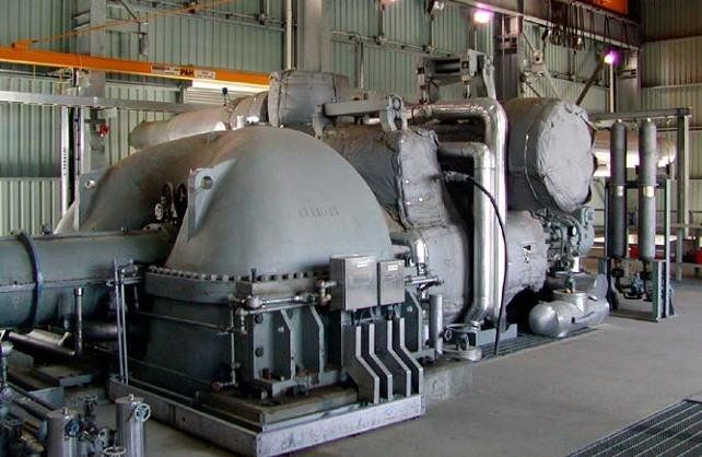
Steam turbine – max. 20 hp – Elliott Group – mechanical drive …
- Multi-YR (MYR) Turbines: A hybrid extension of the YR series, adding 2–9 impulse stages within the same frame footprint. This boosts power output to 14,000 hp (10,440 kW) while improving efficiency by 15–30% and maintaining parts interchangeability. Ideal for retrofits, MYR units produce more power without additional steam consumption, supporting applications in capacity-constrained plants.
- Multi-Stage Steam Turbines: For higher demands, these multi-valve units reach 135,000 hp (100,000 kW), with options for condensing, extraction, induction, and mixed configurations. High-speed models eliminate gearboxes by matching compressor speeds directly, achieving efficiencies over 80% at inlet conditions like 600 psig/750°F (up to 1,300 psig/905°F). Features include solid forged rotors, precision diaphragms, and advanced sealing to minimize leakage.
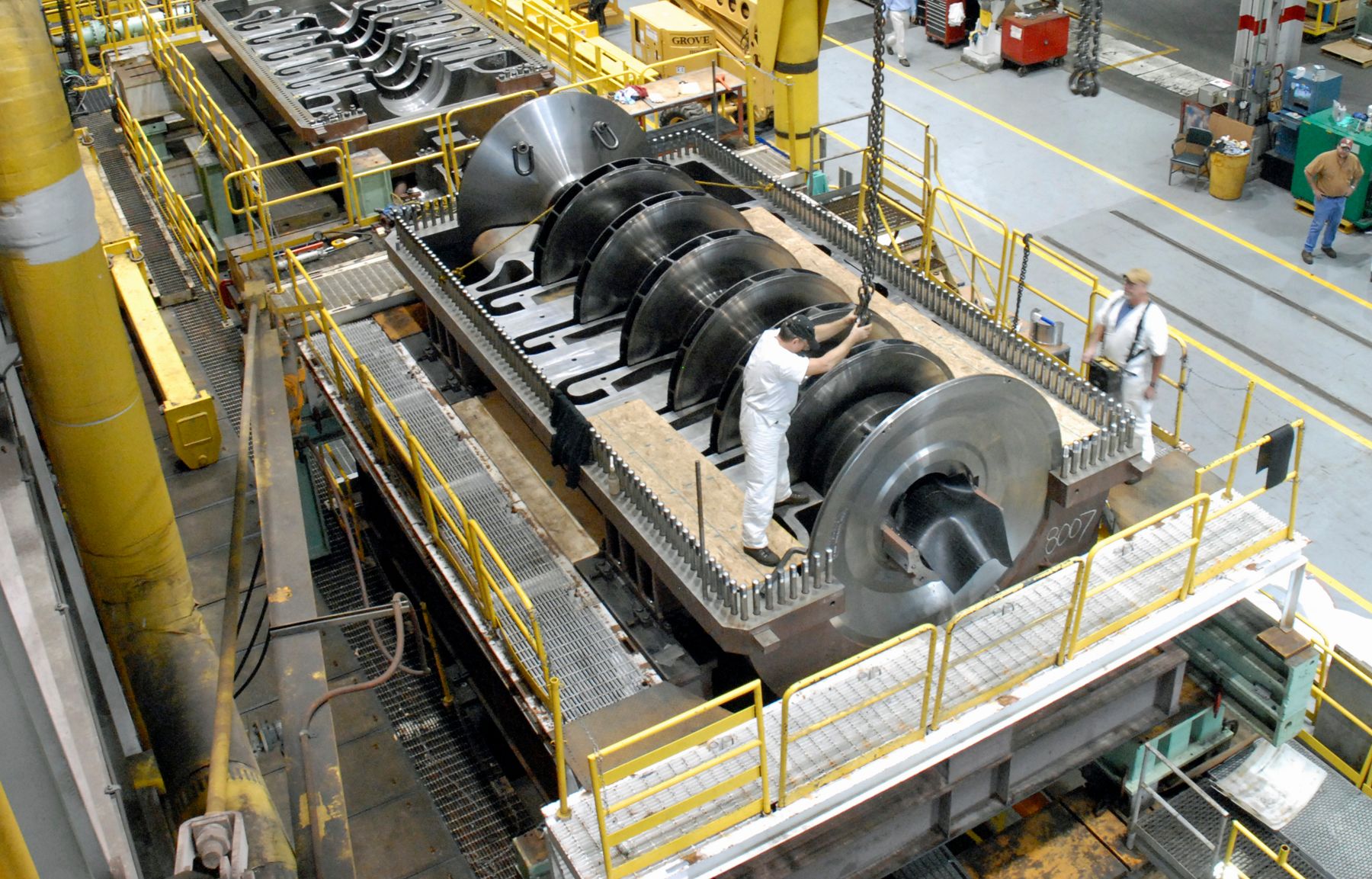
Vendor spotlight: Elliott Group | Turbomachinery Magazine
- Turbine-Generator Sets (STGs): Complete packaged systems from 1 MW to 50 MW, including turbine, gearbox, generator, lube oil system, and controls on a single skid. These are optimized for cogeneration and waste-heat recovery, ensuring seamless integration and rapid deployment.
In May 2025, Elliott launched the Eagle Series steam turbine line, tailored for small industrial and waste-to-energy plants in the U.S., emphasizing modular design for quick installation and enhanced efficiency in low-power applications
Design Features and Reliability
Elliott turbines incorporate industrial-grade features for unmatched uptime:
- Robust Construction: Heavy-duty casings from carbon-moly or chrome-moly alloys, stainless steel blading with shrouded tips to reduce erosion, and integrally forged rotors for structural integrity.
- Advanced Controls: Digital governors with wireless vibration and temperature sensors for predictive maintenance; patented pneumatic partial stroke trip systems (SIL 3 capable) that verify trip valves without shutdown, preventing spurious trips and complying with safety regulations.
- Efficiency Enhancements: Impulse blading optimizes energy extraction; high-speed designs save 12–14% on steam usage, reduce mineral oil and cooling water needs, and shrink footprints by 20%.
- Testing and Compliance: All units undergo no-load mechanical runs and non-destructive testing; full-load testing expanded to 100 MW following a major electrical upgrade at the Pennsylvania facility in October 2025
These elements ensure turbines operate reliably for 30–50 years between major overhauls, even in corrosive or variable-load environments.
Industrial Applications
Elliott turbines power critical processes across industries:
- Oil & Gas and Refining: Driving centrifugal compressors in hydrocracking, hydrotreating, catalytic reforming, and gas boosting.
- Petrochemical and Chemical: Mechanical drives for fans, blowers, and pumps in fertilizer and refining plants.
- Power Generation: Cogeneration STGs and waste-to-energy systems, integrating with renewables for sustainable power.
- Pulp & Paper and Food Processing: Lineshaft drives for paper machines and cane shredders in sugar mills.
The Bengaluru facility, expanded in recent years, serves as a single-source hub for South Asia, including manufacturing, repairs, and customer training. A new service center in Abu Dhabi, set to launch in Q3 2026, will further grow Elliott’s Middle East footprint.
Sustainability and Future Advancements
Elliott is advancing eco-friendly solutions amid growing market demands. The global steam turbine market is projected at $17.8 billion in 2025, with steady growth driven by industrial expansion and energy transitions. High-efficiency designs reduce steam consumption and environmental impact, while compatibility with hydrogen blends and carbon capture systems supports net-zero goals. The aftermarket segment, valued at $4.36 billion in 2025, emphasizes upgrades for longevity and efficiency.

In summary, Elliott steam turbines embody industrial-grade engineering excellence, blending proven reliability with cutting-edge innovations to meet the evolving needs of global industries. As of late 2025, ongoing expansions and new product launches position Elliott as a key player in sustainable, high-performance turbomachinery.
Elliott Steam Turbine: Industrial-Grade Engineering Solutions
Ebara Elliott Energy, operating under the Elliott Group brand, is a premier provider of steam turbines engineered specifically for the rigors of industrial applications. These turbines deliver reliable mechanical drive and power generation solutions across a wide range of operating conditions, with proven performance in continuous-duty environments worldwide. Elliott’s designs emphasize durability, operational flexibility, and long-term value, making them a trusted choice for critical processes where equipment failure is not an option.
Engineering Heritage and Core Principles
Elliott’s steam turbine lineage began in the early 20th century, evolving through strategic developments and acquisitions that established a foundation in robust turbomachinery. The company’s signature single-stage YR turbine, introduced as a refined single-valve design, has become an industry standard with tens of thousands of units in service. Today, as part of Ebara Corporation, Elliott maintains dedicated manufacturing and engineering centers focused on precision craftsmanship and adherence to international standards such as API 611 for general-purpose and API 612 for special-purpose turbines.
The core engineering approach relies on impulse-type staging, where high-pressure steam expands primarily through stationary nozzles to create high-velocity jets that impact curved rotor blades. This method provides excellent tolerance to steam quality variations, low axial thrust, and simplified maintenance—attributes ideally suited to industrial mechanical drives rather than maximum theoretical efficiency in controlled utility settings.
Product Portfolio Overview
Elliott offers a comprehensive range of steam turbines tailored to industrial needs:
- Single-Stage YR Series: Compact, single-valve impulse turbines rated from approximately 50 hp to 3,500 hp standard, with some configurations reaching higher outputs. Available in standardized frames with variants for condensing, back-pressure, and high back-pressure service. These units feature overhung rotors, tilt-pad bearings, and horizontal casing splits for rapid access and minimal downtime.
- Multi-YR Series: An innovative extension of the YR platform, incorporating 2 to 9 additional impulse stages within a modified casing. This configuration increases power output significantly—up to 14,000 hp—while preserving parts interchangeability and foundation compatibility with single-stage models. Multi-YR turbines are particularly valuable for retrofit applications requiring higher capacity without major civil works.
- Multi-Stage Turbines: Multi-valve designs for outputs exceeding 10,000 hp and extending to over 100,000 hp. These include condensing, extraction, induction, and high-speed variants that eliminate reduction gears in certain compressor drive applications. Solid forged rotors, precision diaphragms, and advanced sealing systems ensure structural integrity at elevated pressures and temperatures.
- Turbine-Generator Packages: Fully integrated systems combining turbine, gearbox (when required), generator, lubrication console, and controls on a common baseplate. These packages support cogeneration and standalone power production in the small to medium range, with streamlined installation and commissioning.
Key Design and Performance Features
Elliott turbines incorporate numerous elements that define industrial-grade reliability:
- Heavy-duty materials selection, including chrome-moly casings and stainless steel blading resistant to corrosion and erosion
- Conservative rotor dynamics with generous critical speed margins
- Forced-lubrication systems with tilt-pad bearings for superior load handling and vibration damping
- Digital control systems supporting remote monitoring and predictive maintenance
- Safety features such as overspeed trips, emergency stop valves, and partial-stroke testing capabilities
- Efficiency optimization through refined blade profiles and minimized internal leakage
These characteristics enable service lives of multiple decades between major overhauls, even in challenging conditions involving wet steam, contaminants, or variable loads.
Industrial Applications
Elliott steam turbines serve as prime movers across diverse sectors:
- Oil and gas processing: Driving centrifugal compressors for gas boosting, refrigeration, and pipeline service
- Refining and petrochemical: Powering pumps, fans, and blowers in critical process units
- Chemical and fertilizer production: Reliable drives for synthesis gas compressors and circulation pumps
- Power and cogeneration: Providing mechanical or electrical output in combined heat and power systems
- Pulp and paper: Operating lineshaft drives for high-speed paper machines
- Sugar and food processing: Driving cane shredders and mill tandems in continuous seasonal campaigns
The turbines’ ability to handle varying steam conditions and maintain stable operation under fluctuating loads makes them particularly suitable for process-critical installations.
Service and Support Infrastructure
Elliott maintains a global network of manufacturing, repair, and service facilities to support the installed base. Capabilities include rerates, upgrades, spare parts supply, field service, and training programs. Emphasis on standardized components across product lines ensures rapid response times and minimized inventory requirements for operators.
Ongoing Development Focus
Current engineering efforts concentrate on enhancing efficiency within existing industrial constraints, improving digital integration for condition monitoring, and adapting designs for evolving energy requirements. These advancements maintain Elliott’s position as a provider of practical, field-proven solutions rather than purely theoretical optimizations.
In essence, Elliott steam turbines represent industrial-grade engineering at its most refined—combining time-tested mechanical simplicity with targeted modern enhancements to deliver dependable performance in real-world operating environments. Their continued widespread use across global industries underscores the enduring value of this focused, reliability-centered approach.
Impulse-Type Blading Mechanics in Steam Turbines
Impulse-type blading is the foundational energy transfer mechanism in Elliott steam turbines (YR single-stage, Multi-YR, and most multi-stage models). It relies on the principle of momentum change (impulse) rather than pressure drop across the moving blades, providing robustness, simplicity, and excellent tolerance to wet steam—key advantages for industrial applications.
Basic Principle
In an impulse stage, the entire (or nearly entire) pressure drop for that stage occurs across stationary nozzles. High-pressure steam expands in these nozzles, converting pressure energy almost completely into kinetic energy, producing high-velocity steam jets. These jets then strike the curved moving blades (buckets) mounted on the rotor wheel, changing the steam’s direction and transferring momentum to the blades. The force generated by this momentum change causes the rotor to turn.
Pressure remains essentially constant across the moving blades; only the steam’s velocity decreases as energy is extracted.
This contrasts with reaction blading, where pressure drops significantly across both stationary and moving blades.
Step-by-Step Mechanics of Energy Transfer
- Steam Entry and Nozzle Expansion Steam enters the nozzle at high pressure and relatively low velocity. The nozzle is converging, causing the steam to accelerate rapidly while pressure drops (Bernoulli’s principle: pressure energy → kinetic energy). Exit velocity from the nozzle can reach supersonic speeds in high-pressure drops.
- Jet Impact on Moving Blades The high-velocity jet strikes the leading edge of the curved moving blade. The blade shape is designed to deflect the steam smoothly through approximately 160–170 degrees, reversing much of its tangential velocity component.
- Momentum Change and Force Generation According to Newton’s second and third laws, the force on the blade equals the rate of change of momentum of the steam: F = ṁ × (V₁ – V₂) where ṁ is mass flow rate, V₁ is inlet velocity relative to blade, V₂ is exit velocity relative to blade. The greater the change in tangential velocity (ΔV_tangential), the greater the work output.
- Work Extraction Work per unit mass is given by Euler’s turbine equation: Work = U × (V_{w1} – V_{w2}) where U is blade peripheral speed, V_{w1} and V_{w2} are the tangential (whirl) components of absolute steam velocity at inlet and exit. Maximum work occurs when exit whirl velocity is zero or negative (steam leaves axially or slightly reversed).
- Steam Exit Steam leaves the moving blades at reduced velocity, carrying away residual kinetic energy (exit loss). In single-stage turbines like the Elliott YR, this loss is accepted for simplicity; in multi-stage designs, subsequent stages recover some energy.
Velocity Triangles
The mechanics are best visualized through velocity triangles, which analyze relative velocities at blade inlet and exit:
- Inlet Triangle: Absolute steam velocity (V₁ from nozzle) combines vectorially with blade speed (U) to give relative velocity (W₁) at which steam approaches the blade. Blade inlet angle is matched to W₁ for shock-free entry.
- Exit Triangle: Relative exit velocity (W₂) is determined by blade exit angle. Adding blade speed U vectorially gives absolute exit velocity (V₂). Ideal design minimizes tangential component of V₂.
Optimal blade speed ratio (U/V₁) is approximately 0.45–0.5 for single-row impulse blades, maximizing efficiency.
Rateau Staging in Elliott Designs
Many Elliott YR turbines use two-row wheels (Rateau configuration):
- Steam passes through first moving row → stationary guide vanes → second moving row on the same wheel.
- Guide vanes re-accelerate and redirect steam, allowing a second impulse.
- This extracts more energy from the same pressure drop, improving efficiency without adding full stages.
Advantages of Impulse Blading Mechanics
- Low Axial Thrust: Constant pressure across moving blades results in minimal net axial force, simplifying thrust bearing design.
- Wet Steam Tolerance: High-velocity droplets form primarily in stationary nozzles; relative velocity across moving blades is lower, reducing erosion on rotating parts.
- Robustness: Simple bucket shapes are easier to manufacture and less sensitive to deposits or minor damage.
- Part-Load Stability: Partial-arc admission (common at reduced loads) causes less flow disruption than in reaction designs.
Limitations
- Higher exit velocity losses compared to reaction stages.
- Requires larger wheel diameter for given power (higher U needed to match high V₁).
- Slightly lower peak efficiency than 50% reaction designs in large machines.
Summary
Impulse-type blading mechanics convert steam’s pressure energy into kinetic energy in stationary nozzles, then extract work purely through momentum change as high-velocity jets deflect off moving blades. This straightforward, reliable process—optimized in Elliott turbines through precise nozzle and bucket profiling—delivers the durability and operational forgiveness required for demanding industrial service, even when maximum theoretical efficiency is not the primary goal.
Elliott Steam Turbine – Industrial Steam Power Engineering
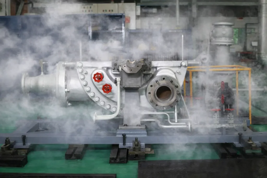
Elliott steam turbines represent a pinnacle of industrial steam power engineering, delivering reliable, efficient conversion of thermal energy into mechanical work for critical process applications worldwide. Designed for continuous operation in harsh industrial environments, these turbines combine time-tested impulse-stage principles with modern materials, controls, and manufacturing precision to meet the exacting demands of oil & gas, petrochemical, refining, power generation, pulp & paper, and food processing industries.
Core Engineering Principles
Elliott turbines are built around impulse-type blading, where high-pressure steam expands almost entirely through stationary nozzles, producing high-velocity jets that impact curved rotor blades. This design prioritizes:
- Reliability: Low axial thrust, minimal pressure drop across rotating blades, and excellent tolerance to wet or contaminated steam.
- Simplicity: Fewer delicate components and straightforward maintenance access via horizontal casing splits.
- Durability: Conservative stress levels, heavy-duty construction, and materials selected for long-term creep and corrosion resistance.
Inlet steam conditions range up to 2,000 psig (138 barg) and 1,005°F (541°C), with exhaust options from vacuum condensing to high back-pressure, enabling integration into diverse steam systems.
Product Range and Configurations
Elliott offers a modular portfolio that scales seamlessly across power requirements:
- Single-Stage YR Turbines The workhorse of industrial steam power, with over 40,000 units installed. Single-valve, overhung impulse design delivers 50–3,500 hp (up to ~5,400 hp optimized). Standardized frames (PYR to DYR) and variants (e.g., high back-pressure DYRHH) ensure rapid delivery and parts availability. Ideal for driving pumps, fans, small compressors, and generators.
- Multi-YR Turbines Hybrid configuration adding 2–9 impulse stages within YR-compatible casings. Power increases to 14,000 hp with 15–30% better steam economy. Drop-in retrofit capability preserves existing foundations and piping—perfect for capacity upgrades without major plant modifications.
- Multi-Stage Turbines Multi-valve designs for higher outputs (10,000–135,000+ hp). Include condensing, extraction/induction, and high-speed gearbox-eliminating models. Solid forged rotors, precision diaphragms, and tilt-pad bearings ensure integrity at extreme conditions. Commonly applied to large compressor trains and power generation.
- Integrated Turbine-Generator Sets Complete skid-mounted packages (1–50 MW) combining turbine, gearbox, generator, lubrication, and controls for cogeneration and waste-heat recovery applications.
Key Engineering Features
- Rotors: Built-up (single-stage) or integrally forged (multi-stage) from high-alloy steels, dynamically balanced to stringent standards.
- Blading: Stainless steel impulse buckets with optimized profiles and shrouded tips to minimize leakage and erosion.
- Bearings and Seals: Tilt-pad journal/thrust bearings with forced lubrication; labyrinth standard, with carbon ring or brush seal upgrades for reduced leakage.
- Casings: Cast or fabricated high-pressure steam chests with separate intermediate and exhaust sections to manage thermal expansion.
- Controls and Safety: Digital governors, wireless sensors for predictive maintenance, overspeed trips, and emergency stop valves.
Manufacturing and Quality Assurance
Primary production occurs in dedicated facilities emphasizing precision:
- CNC machining of critical components
- Non-destructive testing (ultrasonic, magnetic particle, dye penetrant)
- High-speed balancing and no-load mechanical run testing
- Full-load string testing capability for large units
Standardized YR components are inventoried for short lead times, while custom multi-stage units undergo extensive computational fluid dynamics (CFD) and finite element analysis (FEA) during design.
Industrial Applications
Elliott turbines power essential processes:
- Driving centrifugal compressors in gas processing, refrigeration, and pipeline service
- Operating pumps and fans in refining and petrochemical units
- Providing lineshaft power for paper machines and sugar mill tandems
- Generating electricity in cogeneration and renewable steam systems (biomass, geothermal, waste heat)
Their ability to handle variable loads, poor steam quality, and continuous duty makes them the preferred choice where operational uptime directly impacts profitability.
Service and Lifecycle Support
A global network supports the installed base through:
- Rerates and efficiency upgrades
- Rapid spare parts supply leveraging standardization
- Field service, repairs, and training
- Predictive maintenance enabled by digital monitoring
Many units operate for 40–50 years with proper maintenance, delivering exceptional lifecycle value.
Conclusion
Elliott steam turbines embody industrial steam power engineering at its finest—robust, field-proven designs that convert steam energy into reliable mechanical output under real-world conditions. By focusing on impulse-stage simplicity, heavy-duty construction, and practical innovation, Elliott continues to provide engineering solutions that industries depend on for critical, uninterrupted performance.
Rateau Staging in Steam Turbines: Detailed Explanation
Rateau staging, also referred to as pressure compounding in impulse steam turbines, is a method of energy extraction that divides the total steam pressure drop across multiple stages to achieve practical blade speeds and improved overall performance. Named after its inventor, Auguste Rateau, this technique addresses the limitations of single-stage impulse turbines, where a full pressure drop in one set of nozzles results in excessively high steam velocities—often exceeding what rotor blades can efficiently handle without excessive stress, vibration, or inefficiency. Rateau staging is commonly applied in industrial turbines, including some Elliott designs, to enable reliable operation with high-pressure, high-temperature steam from modern boilers.
Historical and Engineering Context
Developed in the late 19th and early 20th centuries, Rateau staging emerged as part of broader advancements in steam turbine compounding. Early impulse turbines, like the de Laval type, suffered from impractical rotor speeds (up to 30,000 rpm) and energy wastage (10–12% of steam kinetic energy lost if not fully absorbed). Rateau’s approach, patented around 1900, focused on pressure compounding to distribute the enthalpy drop incrementally, reducing individual stage velocities and allowing turbines to operate at optimal speeds (typically 3,000–20,000 rpm in industrial units). This made it suitable for mechanical drives and power generation in sectors like oil & gas and petrochemicals, where reliability under variable steam conditions is critical. In engineering terms, it optimizes the conversion of steam’s thermal energy into mechanical work while minimizing structural demands on the rotor and blades.
Mechanics of Rateau Staging
In a Rateau-staged turbine, steam expansion occurs progressively through a series of alternating fixed and moving blade rows, with each “stage” consisting of one ring of stationary nozzles (fixed blades) followed by one ring of moving blades attached to the rotor. The process follows these steps:
- Steam Inlet and Initial Nozzle Expansion: High-pressure, superheated steam from the boiler enters the first set of fixed blades, which act as converging nozzles. Here, a partial pressure drop occurs—typically an equal fraction of the total drop across all stages. According to the energy conservation equation 2V12+h1=2V22+h2 (where V is velocity and h is enthalpy), only a portion of the steam’s enthalpy is converted to kinetic energy, resulting in a moderate-velocity jet exiting the nozzles.
- Energy Transfer in Moving Blades: The steam jet impinges on the curved moving blades (buckets), where nearly all its velocity is absorbed through impulse (momentum change). Pressure remains constant across these blades, as the design ensures no significant expansion here—distinguishing it from reaction staging. The blades deflect the steam by approximately 160–170 degrees, generating tangential force on the rotor. Work extracted per unit mass is given by Euler’s turbine equation: W=U×(Vw1−Vw2), where U is blade peripheral speed, and Vw1, Vw2 are inlet and exit whirl velocities.
- Stage Repetition: The steam, now at reduced pressure but with low residual velocity, enters the next ring of fixed nozzles for another partial expansion and velocity increase. This cycle repeats across multiple stages (commonly 3–10 or more in industrial turbines) until the steam reaches exhaust pressure (e.g., condenser vacuum or back-pressure for process use). Each stage extracts a portion of the total energy, with pressure decreasing stepwise and velocity being regenerated and absorbed repeatedly.
Velocity triangles illustrate the mechanics: At the inlet to moving blades, the absolute steam velocity Va combines with blade speed U to form relative velocity Vr, matched to the blade entrance angle Φ for shock-free entry. At the exit, the fluid angle δ is ideally 90 degrees (zero whirl), maximizing work. The optimum blade velocity is Vb,optimum=2nVa1cosθ1, where n is the number of stages and θ1 is the nozzle angle—reducing required speed by a factor of 1/n compared to single-stage designs.
In Elliott turbines, Rateau principles may integrate with hybrid configurations like Multi-YR, where multiple impulse stages compound pressure drops within a compact casing.

Schematic diagram of a three-stage Rateau (pressure-compounded impulse) turbine, showing alternate rings of fixed nozzles and moving blades with progressive pressure drops.
Differences from Other Compounding Methods
Rateau staging is one of several compounding techniques, each addressing energy extraction differently:
- Velocity Compounding (e.g., Curtis Staging): Involves a single full pressure drop in the initial nozzles, followed by velocity absorption across multiple rows of moving blades on the same wheel, separated by fixed redirecting vanes (no pressure change in vanes). Rateau differs by distributing pressure drops across multiple nozzle sets, resulting in lower per-stage velocities and more uniform energy distribution. Curtis is better for high initial velocities but suffers higher friction losses from repeated redirections.

Schematic of a Curtis stage (velocity compounding) for comparison, showing one pressure drop and multiple velocity absorptions.
- Pressure-Velocity Compounding: A hybrid where pressure drops are staged (like Rateau), but each pressure stage includes velocity compounding (2–4 moving rows per nozzle set). This combines benefits but increases complexity.
- Reaction Staging: Pressure drops across both fixed and moving blades (typically 50/50), with reaction force adding to impulse. Rateau is purely impulse-based, with no pressure change in moving blades, making it more tolerant to wet steam but potentially less efficient in large utility applications.
Rateau is specifically for impulse turbines, while reaction turbines use only pressure compounding.
Advantages
- Reduced Blade Speeds: Distributes expansion, lowering rotor RPM and centrifugal stresses, enabling practical designs without gearboxes or excessive vibration.
- Improved Efficiency at Lower Velocities: Achieves high power output with moderate steam velocities per stage, reducing losses from supersonic flows or blade erosion.
- Scalability for High-Pressure Steam: Handles modern boiler outputs effectively, with work ratios decreasing progressively (e.g., 3:1 for two stages, 5:3:1 for three), allowing balanced loading.
- Robustness: Better wet-steam tolerance since high-velocity droplets form in fixed nozzles, protecting rotating blades.
Disadvantages
- Design Complexity: Nozzles must be airtight to contain pressure drops, requiring precise sealing and manufacturing.
- Larger Physical Size: Multiple stages increase turbine length and diameter compared to velocity-compounded designs.
- Uneven Work Distribution: Low-pressure stages produce less work, potentially leading to inefficiencies in the final stages.
- Friction Losses: While lower than in velocity compounding, repeated accelerations cause some energy dissipation as heat.
In summary, Rateau staging optimizes impulse turbines for industrial reliability by staging pressure drops, making it a cornerstone of steam power engineering in applications like Elliott turbines. Its mechanics ensure efficient, durable performance, though at the cost of added size and complexity compared to simpler single-stage alternatives.
Rateau Staging in Steam Turbines: Detailed Explanation
Rateau staging is a form of pressure compounding used in impulse-type steam turbines to divide the total available steam pressure drop (and associated enthalpy drop) across multiple successive stages. This technique, developed by French engineer Auguste Rateau in the early 1900s, allows practical rotor speeds, reasonable blade heights, and acceptable efficiency levels when dealing with large pressure ratios—conditions common in modern industrial steam systems.
Fundamental Purpose
In a simple single-stage impulse turbine (like the classic de Laval design), the entire pressure drop occurs in one set of nozzles, producing extremely high steam exit velocities—often supersonic. To extract maximum work, the rotor blade speed must approach half this velocity, resulting in impractically high rotational speeds (20,000–30,000 rpm or more), excessive centrifugal stresses, and significant exit kinetic energy losses.
Rateau staging solves this by distributing the total enthalpy drop evenly (or near-evenly) across several stages. Each stage handles only a fraction of the total pressure drop, producing moderate steam velocities that can be efficiently absorbed at realistic blade speeds.
Detailed Mechanics of a Rateau Stage
A typical Rateau-staged turbine consists of repeating units, each comprising:
- Stationary Nozzle Ring (Fixed Blades) High-pressure steam from the previous stage (or inlet for the first stage) enters a ring of converging nozzles mounted in a diaphragm or casing partition. A partial pressure drop occurs here, converting enthalpy into kinetic energy. Steam exits as a high-velocity jet at lower pressure but higher specific volume. The nozzle angle is optimized (typically 12–20 degrees from axial) to direct the jet tangentially onto the following moving blades.
- Moving Blade Row (Rotor Blades) The steam jet strikes curved impulse buckets attached to the rotor wheel. Pressure remains essentially constant across the moving blades—the hallmark of pure impulse design. Energy transfer occurs solely through momentum change: the steam is deflected sharply (often 160–170 degrees), reducing its tangential velocity component dramatically. Work is extracted according to Euler’s turbine equation: Work per stage = U × (V_{w1} – V_{w2}) where U is blade peripheral speed, V_{w1} is inlet whirl velocity, and V_{w2} is exit whirl velocity (ideally zero or negative).
- Transition to Next Stage Steam exits the moving blades with low residual velocity and enters the next nozzle ring directly. The process repeats: partial expansion in nozzles → velocity increase → impulse on next moving row → pressure reduction.
This sequence continues across all stages until the steam reaches the desired exhaust pressure.
Velocity Triangles in Rateau Staging
Velocity diagrams are critical for understanding stage efficiency:
- Inlet to Moving Blades: Absolute steam velocity from nozzles (V₁) combines vectorially with blade speed U to give relative inlet velocity W₁. The blade leading edge angle matches the direction of W₁ for shock-free entry.
- Exit from Moving Blades: Relative exit velocity W₂ is governed by the blade trailing edge angle. Adding U vectorially yields absolute exit velocity V₂. Optimal design minimizes the whirl component of V₂, reducing carry-over losses to the next stage.
Because each stage handles only a fraction of the total drop, V₁ per stage is moderate, allowing U/V₁ ≈ 0.45–0.5 (optimal for impulse blades) at practical rotor speeds.
Comparison with Other Staging Methods
- Velocity Compounding (Curtis Stage) Full pressure drop in one nozzle set → very high V₁ → multiple moving rows (usually 2) on the same wheel, separated by stationary reversing blades that redirect (but do not expand) the steam. Rateau differs by using multiple pressure drops (one per stage) rather than multiple velocity absorptions per pressure drop. Curtis achieves higher work per wheel but with greater friction losses and complexity.
- Pressure-Velocity Compounding Combines Rateau (multiple pressure stages) with Curtis (2–4 moving rows per pressure drop). Used in some medium-pressure turbines for compactness.
- Reaction Staging (Parsons) Pressure drop split ~50/50 between fixed and moving blades; moving blades act as expanding nozzles. Rateau is purely impulse—no pressure drop in moving blades—offering better wet-steam tolerance and lower axial thrust.
Advantages of Rateau Staging
- Practical rotor speeds and reasonable centrifugal stresses
- Uniform blade heights possible (unlike expanding flow in single-stage designs)
- Good efficiency over a range of pressure ratios
- Excellent wet-steam tolerance: high-velocity droplets form in stationary nozzles, sparing rotating blades from severe erosion
- Simpler thrust balance due to low axial forces
Disadvantages
- Longer axial length (more diaphragms and wheels)
- Higher manufacturing precision required for nozzle/diaphragm sealing
- Slightly uneven work distribution: early stages produce more work than later ones due to higher density
- Cumulative leakage losses across multiple diaphragms
Application in Elliott Turbines
While many Elliott single-stage YR turbines use a simple single wheel (sometimes with two moving rows for partial velocity compounding), larger multi-stage Elliott turbines and Multi-YR configurations frequently employ Rateau-style pressure compounding. The extended casing houses multiple diaphragm-supported nozzle rings and rotor wheels, allowing power outputs far beyond single-stage limits while retaining the impulse design’s robustness.
In summary, Rateau staging transforms the impulse turbine from a high-speed, limited-ratio device into a versatile, industrial-grade machine capable of efficiently handling large pressure drops at practical speeds and with exceptional durability—making it a cornerstone of reliable steam power engineering in demanding applications.
Elliott Steam Turbine Technology in Industrial Power Systems
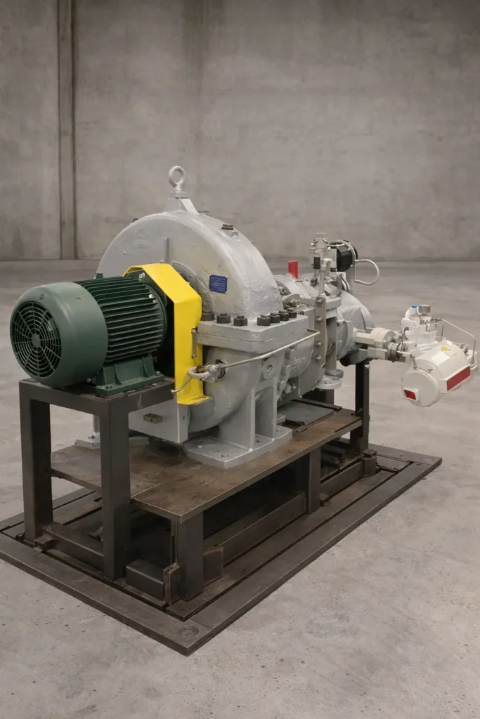
Ebara Elliott Energy (Elliott Group) delivers advanced steam turbine technology tailored for industrial power systems, providing reliable mechanical drives and power generation in demanding sectors. These turbines convert steam thermal energy efficiently into shaft power, supporting continuous operations in oil & gas, petrochemical, refining, chemical processing, pulp & paper, food processing, and cogeneration facilities.
Core Technology: Impulse Design and Staging
Elliott turbines primarily use impulse blading, where steam expands fully in stationary nozzles to create high-velocity jets that impact curved moving blades. This design offers low axial thrust, superior wet-steam tolerance, and robustness against contaminants—essential for industrial environments with variable steam quality.
- Single-Stage YR Series: Standardized single-valve impulse turbines with overhung rotors, rated from 20 hp (15 kW) to over 5,000 hp (4,027 kW). Frames range from small PYR to large DYR, with variants for high back-pressure and modified exhausts.
- Multi-YR (MYR) Series: Adds 2–9 impulse stages in a YR-compatible casing, boosting output to 14,000 hp (10,440 kW) with 15–30% better efficiency while enabling drop-in retrofits.
- Multi-Stage Series: Multi-valve configurations up to 175,000 hp (130,000 kW), including extraction/induction and high-speed models (up to 20,000 rpm) that eliminate gearboxes.
Inlet conditions handle up to 2,000 psig (138 barg) and 1,005°F (541°C), with compliance to API 611/612 standards.
Integration in Industrial Power Systems
Elliott turbines serve as prime movers in mechanical drive and cogeneration setups:
- Mechanical Drives: Direct or geared coupling to centrifugal compressors (gas boosting, refrigeration), pumps, fans, blowers, cane shredders, and paper machine lineshafts. High-speed designs reduce system complexity and footprint.
- Power Generation: Turbine-generator sets (STGs) from 50 kW to 50 MW, often induction or synchronous, for on-site electricity in combined heat and power (CHP) or waste-heat recovery. Packages include gearbox, generator, lube system, and controls on a single baseplate.
- Cogeneration and Efficiency: Back-pressure or extraction models reuse exhaust steam for process heating, maximizing energy utilization and reducing utility dependence.
Key Features Enhancing Industrial Performance
- Reliability: Solid forged rotors, tilt-pad bearings, labyrinth/carbon seals, and heavy-duty casings ensure decades of service with minimal overhauls.
- Controls and Monitoring: Digital systems with predictive maintenance via wireless sensors; advanced trip mechanisms for safety.
- Customization: Engineered solutions with CFD/FEA optimization; standardized YR components for short lead times.
- Global Manufacturing: Facilities in Jeannette (USA), Sodegaura (Japan), and Bengaluru (India) support regional needs, including full testing capabilities.
As of late 2025, Elliott continues advancements in high-efficiency designs and service expansions (e.g., new Middle East facilities), aligning with energy transition demands while maintaining focus on proven industrial reliability.
Elliott steam turbine technology remains a cornerstone of industrial power systems, offering versatile, durable solutions that optimize energy conversion and support operational uptime in critical processes worldwide.
Comparison: Impulse vs. Reaction Steam Turbines
Impulse and reaction turbines represent the two primary blading philosophies in steam turbine design. Elliott turbines (YR, Multi-YR, and multi-stage models) are predominantly impulse-type, optimized for industrial mechanical drives. Reaction turbines are more common in large-scale utility power generation (e.g., Siemens, GE, Mitsubishi). The key difference lies in how pressure drop and energy transfer are distributed across stationary and moving blades.
Summary Table
| Aspect | Impulse Turbines (Elliott Standard) | Reaction Turbines |
|---|---|---|
| Pressure Drop per Stage | Almost entirely in stationary nozzles (~100%) | Shared ~50/50 between stationary and moving blades |
| Energy Transfer Mechanism | Primarily impulse (momentum change) | Impulse + reaction (pressure drop across moving blades) |
| Blade Design | Moving blades: symmetric bucket shape, constant area | Moving blades: airfoil shape, converging passage |
| Degree of Reaction | ~0% (pure impulse) | Typically 50% (Parsons type) |
| Peak Isentropic Efficiency | 80–87% (industrial multi-stage) | 88–92% (large utility multi-stage) |
| Axial Thrust | Low (pressure balanced across moving blades) | High (pressure difference across moving blades) |
| Wet Steam/Erosion Tolerance | Excellent (high-velocity droplets hit stationary nozzles) | Moderate (requires moisture removal, hardened edges) |
| Exit Velocity Loss | Higher (steam leaves moving blades at significant velocity) | Lower (gradual acceleration reduces exit kinetic energy) |
| Physical Size | Larger wheel diameter for given power | Smaller diameter, more stages possible |
| Rotational Speed | Suited to both high (industrial) and moderate speeds | Favors moderate speeds (3,000/3,600 rpm) in large machines |
| Part-Load Performance | Good (robust to partial-arc admission) | More sensitive (risk of flow separation) |
| Manufacturing Complexity | Simpler blade shapes, easier maintenance | Precise airfoil tolerances, tighter clearances |
| Typical Applications | Industrial mechanical drives, small/medium power | Large central-station power generation |
Detailed Comparison
- Pressure Drop and Flow Dynamics
- Impulse: Steam expands fully in stationary nozzles → high-velocity jets → impact moving blades with nearly constant pressure across them. Work is extracted purely from momentum change.
- Reaction: Steam expands partially in stationary blades and continues expanding in moving blades (which act as nozzles). Additional work comes from reaction force as steam accelerates through moving passages.
- Velocity Triangles
- Impulse: High inlet absolute velocity (V₁) from nozzles; optimal blade speed ratio U/V₁ ≈ 0.45–0.5. Exit velocity remains significant, contributing to exit loss.
- Reaction: Lower V₁ per stage; blade speed ratio closer to 0.7–0.8. Gradual velocity increase reduces exit loss.
- Efficiency Reaction turbines achieve higher peak efficiency in large machines due to better compounding of velocity and lower exit losses. However, impulse designs close the gap in industrial sizes and offer advantages in real-world operating conditions.
- Mechanical Design Implications
- Impulse: Minimal axial thrust simplifies thrust bearing design. Robust bucket shapes tolerate deposits and minor damage.
- Reaction: Significant axial thrust requires balancing pistons or large thrust bearings. Symmetric blade profiles are more sensitive to fouling.
- Wet Steam and Erosion Impulse staging protects rotating blades: high-velocity moisture droplets form in stationary nozzles and impact fixed components. Reaction stages accelerate droplets in moving blades, increasing erosion risk on subsequent stationary rows.
- Operational Flexibility Impulse turbines handle part-load and variable steam conditions better, making them ideal for industrial processes with fluctuating demands.
Why Elliott Chooses Impulse Design
Elliott prioritizes impulse blading for its industrial focus because:
- Superior reliability in harsh, variable conditions
- Excellent tolerance to poor steam quality
- Simpler maintenance and longer service life
- Lower sensitivity to off-design operation
While reaction turbines dominate large utility applications where maximum cycle efficiency justifies added complexity, impulse designs remain the optimal choice for mechanical drives and medium-power industrial systems—the core market for Elliott turbines.
In conclusion, the selection between impulse and reaction turbines is driven by application priorities: impulse for ruggedness and reliability in industrial service; reaction for highest efficiency in large-scale, controlled-environment power generation.
Curtis vs. Rateau Staging in Impulse Steam Turbines
Both Curtis and Rateau staging are methods of compounding used in impulse-type steam turbines to extract more work from a given steam pressure drop without requiring impractically high rotor speeds. They achieve this in fundamentally different ways: Curtis uses velocity compounding, while Rateau uses pressure compounding.
1. Fundamental Principle
- Curtis Staging (Velocity Compounding) The entire available pressure drop occurs in one single set of stationary nozzles. This produces a very high steam exit velocity. The high-velocity jet is then passed through multiple rows of moving blades (typically 2, sometimes 3–4) on the same rotor wheel, separated by stationary reversing (or guide) blades that redirect the steam but do not expand it further. Each moving row absorbs a portion of the kinetic energy, progressively reducing the steam velocity before it exits.
- Rateau Staging (Pressure Compounding) The total pressure drop is divided across multiple separate stages, each consisting of one ring of stationary nozzles followed by one ring of moving blades on its own rotor wheel. Only a fraction of the total pressure drop occurs in each nozzle set, producing moderate steam velocities. Each stage extracts work independently, and the process repeats across several wheels.
2. Steam Flow and Energy Transfer
- Curtis
- One large enthalpy/pressure drop → very high nozzle exit velocity (often supersonic).
- Velocity is compounded: first moving row absorbs ~50–60% of kinetic energy, steam is redirected by stationary blades, second moving row absorbs most of the remainder.
- Pressure remains essentially constant after the initial nozzles.
- Rateau
- Multiple smaller enthalpy/pressure drops → moderate velocity regenerated in each nozzle set.
- Each stage operates like a miniature single-stage impulse turbine.
- Pressure decreases progressively stage by stage.
3. Velocity Triangles and Blade Speed Ratio
- Curtis Optimal blade speed U is approximately half the initial jet velocity divided by the number of moving rows. For a two-row Curtis stage, U/V₁ ≈ 0.25 (lower than the 0.45–0.5 ideal for single-row impulse). This allows lower rotor speeds but introduces higher friction and redirection losses.
- Rateau Each stage has its own moderate V₁, so U/V₁ ≈ 0.45–0.5 per stage—close to the theoretical optimum for impulse blading. Higher per-stage efficiency.
4. Physical Configuration
- Curtis Compact axially: multiple moving rows on one wheel, fewer diaphragms. Larger wheel diameter needed to achieve sufficient blade speed.
- Rateau Longer axially: one moving row per wheel, multiple diaphragms and wheels. Smaller individual wheel diameters possible.
5. Efficiency
- Curtis Higher friction and redirection losses due to multiple deflections. Typical stage efficiency lower than Rateau (especially with more than two rows). Better suited to very high pressure ratios where a single nozzle drop would produce extreme velocities.
- Rateau Higher per-stage efficiency due to optimal velocity ratio and fewer redirection losses. Overall turbine efficiency generally superior for most industrial pressure ratios.
6. Advantages and Disadvantages
| Aspect | Curtis Staging (Velocity Compounding) | Rateau Staging (Pressure Compounding) |
|---|---|---|
| Axial Length | Short (compact) | Longer (more stages) |
| Wheel Diameter | Larger | Smaller per stage |
| Efficiency | Moderate (higher losses from redirections) | Higher (optimal velocity ratio per stage) |
| Rotor Speed | Lower for given pressure ratio | Higher but still practical |
| Manufacturing Complexity | More complex blade shapes and precise clearances | Simpler per stage, but more diaphragms |
| Wet Steam Tolerance | Good | Excellent |
| Typical Use | Early high-pressure turbines, some medium-pressure | Most modern industrial impulse turbines |
7. Application in Elliott Turbines
- Elliott single-stage YR turbines sometimes incorporate a mild form of velocity compounding with two moving rows on the same wheel (similar to a simple Curtis arrangement) to extract more energy without adding full stages.
- Larger Elliott multi-stage and Multi-YR turbines predominantly use Rateau-style pressure compounding, with multiple wheels and diaphragms, to achieve high power output while maintaining the impulse design’s robustness and efficiency.
Summary
- Curtis is axially compact and allows very low rotor speeds but sacrifices efficiency due to redirection losses. It was historically important for early high-pressure machines.
- Rateau offers better efficiency, simpler per-stage design, and greater flexibility for a wide range of pressure ratios, making it the preferred choice for most modern industrial impulse turbines, including those from Elliott.
In practice, Rateau staging has largely superseded Curtis in new designs except in specific niche applications requiring extreme compactness or very low speeds.
Elliott Steam Turbine Technology: In-Depth Overview
Ebara Elliott Energy, operating under the Elliott Group brand, is a leading global manufacturer of steam turbines specifically engineered for industrial applications. With a heritage spanning over 110 years, Elliott has refined its technology to deliver highly reliable, efficient, and adaptable steam power solutions that excel in continuous-duty environments where operational uptime is critical.
Engineering Philosophy and Design Principles
Elliott turbines are built on a foundation of impulse-type blading combined with pressure compounding in multi-stage configurations. This design philosophy emphasizes:
- Robustness and Longevity: Conservative stress levels, heavy-duty materials, and generous safety margins enable service lives of 30–50 years between major overhauls.
- Operational Forgiveness: Superior tolerance to wet steam, contaminants, and variable loads—common in industrial processes.
- Simplicity: Minimal moving parts, horizontal casing splits for easy access, and standardized components to reduce maintenance complexity and spare parts inventory.
- Customization with Standardization: Core frames and components are standardized for rapid delivery, while critical elements (nozzles, blading, rotors) are tailored to specific steam conditions.
The company adheres rigorously to industry standards, including API 611 for general-purpose and API 612 for special-purpose mechanical drives, ensuring seamless integration into oil & gas and petrochemical systems.
Detailed Product Line Breakdown
- Single-Stage YR Turbines The flagship product line, with more than 40,000 units operating worldwide.
- Power range: 20 hp to approximately 5,400 hp (15–4,027 kW).
- Frame sizes: PYR (smallest, ~200 hp), AYR, BYR, CYR, up to DYR (largest single-stage).
- Key features: Single throttle valve, overhung impulse rotor, two-row blading on many models for enhanced energy extraction, tilt-pad bearings, labyrinth seals.
- Variants: High back-pressure models (BYRH, CYRH, DYRHH) for process steam recovery up to 400 psig exhaust; modified exhaust configurations (DYRM, DYRN) for optimized flow matching.
- Applications: Ideal for driving small-to-medium compressors, pumps, fans, blowers, and small generators where compactness and quick delivery are priorities.
- Multi-YR (MYR) Turbines A direct evolution of the YR platform, extending the casing to incorporate 2 to 9 impulse stages while retaining full mechanical compatibility with single-stage units.
- Power range: Up to 14,000 hp (10,440 kW).
- Efficiency improvement: Typically 15–30% lower specific steam consumption than equivalent single-stage YR.
- Retrofit advantage: Same foundation bolt pattern, centerline height, coupling interface, bearing housing, and many auxiliaries—enabling capacity upgrades during planned outages with minimal civil work.
- Applications: Debottlenecking existing plants, efficiency upgrades, and new installations requiring higher power in constrained spaces.
- Full Multi-Stage Turbines Multi-valve, multi-wheel designs for larger power requirements.
- Power range: 5,000 hp to over 175,000 hp (130,000 kW).
- Configurations: Condensing, non-condensing/back-pressure, extraction (single or double), admission/induction, and combined types.
- High-speed models: Operate up to 20,000 rpm to directly match driven equipment speeds, eliminating reduction gearboxes and associated losses.
- Rotor design: Integrally forged from high-alloy steels (no shrunk-on discs), ensuring maximum integrity under high thermal and mechanical loads.
- Applications: Large compressor drives in refineries and gas plants, major utility cogeneration, and industrial power generation.
- Turbine-Generator Sets (STGs) Complete packaged systems integrating turbine, gearbox (when required), generator, lubrication console, and digital controls on a common baseplate.
- Power range: 50 kW to 50 MW.
- Configurations: Induction or synchronous generators, suitable for island-mode or grid-parallel operation.
- Applications: Cogeneration, waste-heat recovery, biomass, geothermal, and standalone industrial power supply.
Advanced Design Features
- Blading: Precision-machined stainless steel impulse buckets with optimized aerodynamic profiles and shrouded tips to minimize tip leakage and erosion.
- Sealing Systems: Labyrinth seals standard; optional carbon ring or advanced brush seals for reduced steam leakage in high-pressure applications.
- Bearings: Tilt-pad journal and thrust bearings with forced-oil lubrication for superior stability and load capacity.
- Control and Safety Systems: Electronic governors with overspeed protection, emergency trip valves, and modern options for wireless vibration/temperature monitoring to enable predictive maintenance.
- Materials: Chrome-moly or higher alloy casings for elevated temperatures; corrosion-resistant coatings and materials for aggressive steam environments.
Manufacturing and Testing Excellence
Elliott maintains dedicated turbomachinery centers with comprehensive capabilities:
- Advanced CNC machining for rotors, diaphragms, and blading
- High-speed dynamic balancing
- Non-destructive examination (ultrasonic, magnetic particle, radiography)
- Mechanical run testing under vacuum or load conditions
- Full-string testing for large assemblies
Standardized YR components are maintained in inventory for delivery times as short as weeks, while engineered multi-stage units typically require 12–24 months.
Global Service and Support
An extensive network provides:
- Field service and emergency response
- Rerates, upgrades, and conversions
- Spare parts with rapid global logistics
- Training programs and remote diagnostics
This infrastructure ensures maximum availability of the installed base, with many units achieving decades of continuous operation.
Elliott steam turbine technology continues to set the benchmark for industrial steam power engineering—delivering proven, adaptable solutions that balance performance, reliability, and lifecycle value in the world’s most demanding process environments.
Comparison: Elliott vs. GE Steam Turbines
Elliott (Ebara Elliott Energy) and GE (GE Vernova Steam Power) are both established steam turbine manufacturers, but they target different market segments with distinct strengths. Elliott specializes in industrial mechanical drives and small-to-medium power applications, emphasizing ruggedness and reliability in harsh environments. GE Vernova focuses on large-scale utility and combined-cycle power generation, including nuclear and high-capacity plants, with a broader global installed base.
Summary Comparison Table
| Aspect | Elliott (Ebara Elliott Energy) | GE Vernova Steam Power |
|---|---|---|
| Primary Market Focus | Industrial mechanical drives (oil & gas, petrochemical, refining, pulp & paper, food processing) | Large utility power generation, combined-cycle, nuclear |
| Power Range | 20 hp–175,000 hp (15 kW–130 MW); STGs up to 50 MW | Up to 1,770 MW (e.g., Arabelle for nuclear); broad range for industrial up to ~135 MW |
| Typical Applications | Compressor/pump/fan drives, cogeneration, waste-heat recovery | Combined-cycle plants (35% of global), nuclear turbine islands, large industrial |
| Design Type | Predominantly impulse (YR series iconic for single-stage) | Mix of impulse and reaction; advanced reaction in large units |
| Key Strengths | Rugged reliability in extreme conditions, standardization (YR frames), quick delivery, retrofit ease (Multi-YR) | High efficiency in large-scale, advanced materials/coatings, massive installed base (>195 GW in combined-cycle) |
| Efficiency | 80–87% (industrial multi-stage) | Up to 92%+ in large utility/combined-cycle |
| Installed Base | >40,000 YR units; strong in industrial niches | Thousands of units; equips 35% of world’s combined-cycle plants |
| Global Presence | Facilities in USA, Japan, India; growing Middle East service | Extensive global network; strong in nuclear (Arabelle) |
| Recent Developments (2025) | High-speed designs, wireless monitoring, renewable integration | Modernizations, life extensions, nuclear focus (post-EDF deal) |
Detailed Comparison
- Scale and Power Output Elliott excels in small-to-medium sizes, with the legendary YR single-stage series (up to ~5,400 hp) and multi-stage up to 175,000 hp, optimized for mechanical drives. GE handles massive outputs, including the world’s largest (1,770 MW Arabelle), and dominates high-capacity combined-cycle and nuclear applications.
- Design and Technology Elliott’s impulse designs prioritize durability, wet-steam tolerance, and simplicity—ideal for variable industrial conditions. GE employs advanced reaction/impulse hybrids in large units, focusing on peak efficiency, flexibility (e.g., fast startup), and integration with gas turbines/HRSGs.
- Applications and Market Position Elliott dominates niche industrial drives (e.g., refinery compressors, sugar mills) where reliability in harsh environments is key. GE leads in utility-scale power, with significant nuclear involvement (e.g., Arabelle turbines post-acquisition adjustments).
- Reliability and Service Life Both offer long-life designs, but Elliott’s YR units are renowned for decades of operation in extreme conditions with minimal overhauls. GE emphasizes life extensions and upgrades for its vast fleet.
- Efficiency and Innovation GE achieves higher peak efficiencies in large machines due to scale and advanced aerodynamics. Elliott focuses on practical industrial efficiency, with innovations like Multi-YR retrofits and high-speed gearbox-free drives.
Conclusion
Elliott and GE serve complementary segments: Choose Elliott for rugged, cost-effective industrial mechanical drives and small cogeneration. Choose GE Vernova for high-efficiency, large-scale utility or combined-cycle power generation. In overlapping medium industrial ranges, Elliott often wins on reliability and lead time, while GE on integrated plant performance. Both remain key players in the evolving steam turbine market amid energy transitions
Elliott vs. GE Steam Turbines: Detailed Comparison
Elliott (Ebara Elliott Energy) and GE Vernova Steam Power represent two distinct approaches to steam turbine engineering, shaped by their respective market focuses and historical legacies. Elliott excels in compact, rugged industrial mechanical drives and small-to-medium cogeneration, while GE dominates large-scale utility power generation, including combined-cycle and nuclear applications.
1. Market Focus and Applications
- Elliott: Primarily targets industrial process drives where reliability in harsh, variable conditions is paramount. Common uses include centrifugal compressors in refineries and gas plants, pumps and fans in petrochemical facilities, lineshaft drives in pulp & paper mills, cane shredders in sugar production, and small turbine-generator sets for on-site power. Elliott turbines thrive in environments with wet steam, contaminants, fluctuating loads, and limited maintenance windows.
- GE Vernova: Concentrates on utility-scale electricity production, equipping combined-cycle plants, conventional steam plants, and nuclear turbine islands. GE turbines power massive grid-connected facilities, often integrated with gas turbines or heat recovery steam generators (HRSGs) for optimal cycle efficiency.
2. Power Range and Scale
- Elliott: From 20 hp single-stage YR units to multi-stage models exceeding 175,000 hp (130 MW). Turbine-generator packages typically up to 50 MW. This range suits distributed industrial power and mechanical drives rather than gigawatt-scale plants.
- GE: Covers a vastly broader spectrum, from industrial sizes overlapping Elliott up to the world’s largest steam turbines (e.g., 1,000–1,770 MW class for nuclear and supercritical coal/gas applications). GE handles complete turbine islands for multi-gigawatt power stations.
3. Design Philosophy and Blading
- Elliott: Predominantly impulse-type with Rateau-style pressure compounding in multi-stage units. Emphasis on simplicity, low axial thrust, wet-steam tolerance, and ease of maintenance. Single-stage YR designs use overhung rotors and robust bucket blading; multi-stage units feature integrally forged rotors.
- GE: Employs advanced reaction blading in large units, often with 50% degree of reaction for superior efficiency. Designs incorporate sophisticated 3D aerodynamic profiling, advanced coatings, and hybrid impulse-reaction stages. GE prioritizes peak thermodynamic performance and operational flexibility (fast startup, load following).
4. Efficiency
- Elliott: Achieves 80–87% isentropic efficiency in optimized multi-stage configurations—excellent for industrial scales where practical reliability outweighs marginal efficiency gains.
- GE: Reaches 88–92%+ in large utility turbines due to scale effects, longer last-stage blades, and refined reaction staging. Combined-cycle integrations push overall plant efficiencies beyond 60%.
5. Reliability and Durability
- Elliott: Legendary for decades-long service in extreme conditions with minimal overhauls. The YR series’ standardization and impulse design contribute to exceptional uptime in dirty or variable steam environments.
- GE: Highly reliable in controlled utility settings, with extensive life-extension programs for aging fleets. Large units require more precise operating conditions and maintenance schedules.
6. Manufacturing and Delivery
- Elliott: Benefits from standardized YR components stocked for short lead times (weeks for standard frames). Custom multi-stage units take 12–24 months. Facilities emphasize precision for industrial tolerances.
- GE: Massive production scale for utility turbines, often with longer lead times due to size and customization. Strong focus on supply chain for large forgings and last-stage blades.
7. Service and Support
Both companies maintain global networks, but:
- Elliott: Specializes in rapid response for industrial sites, rerates, Multi-YR retrofits, and spare parts leveraging standardization.
- GE: Offers comprehensive fleet management, digital solutions, and long-term service agreements for utility operators.
8. Current Positioning (as of December 2025)
- Elliott: Continues strong growth in industrial sectors, particularly oil & gas recovery, renewable steam integration (biomass, waste heat), and efficiency upgrades via Multi-YR conversions.
- GE Vernova: Focuses on energy transition support—modernizing existing plants, nuclear advancements, and hydrogen-capable designs—while maintaining dominance in large combined-cycle projects.
Conclusion
Elliott and GE serve complementary rather than directly competing segments. Elliott is the preferred choice for rugged, cost-effective industrial mechanical drives and distributed power where operational forgiveness and quick deployment matter most. GE excels in maximizing efficiency and scale for utility-grade electricity production. In the medium industrial range where they overlap, selection typically depends on priorities: Elliott for proven durability and standardization; GE for integrated plant performance and advanced thermodynamic optimization. Both remain vital to global steam power infrastructure.
Elliott vs. GE Steam Turbines: In-Depth Comparison
Building on the core differences in market focus and design philosophy, here is a more detailed examination of how Elliott and GE Vernova steam turbines compare across technical, operational, and commercial dimensions.
Technical Design and Performance Characteristics
- Blading and Staging Elliott turbines rely almost exclusively on impulse blading with Rateau-style pressure compounding in multi-stage units. This results in low axial thrust, simple thrust bearing requirements, and outstanding resistance to erosion from wet steam. Blade profiles are robust bucket shapes optimized for momentum transfer rather than fine aerodynamic finesse. GE employs advanced reaction blading (typically 50% degree of reaction) in its large turbines, often combined with impulse stages in high-pressure sections. This allows superior velocity compounding and reduced exit losses, contributing to higher overall efficiencies. GE invests heavily in 3D aerodynamic design, variable-reaction blading, and advanced tip sealing to minimize losses.
- Materials and Construction Both manufacturers use high-quality alloys, but applications differ. Elliott favors proven chrome-moly and stainless steels suited to industrial temperatures (up to 1,005°F/541°C) and corrosive environments. Rotors are either built-up (single-stage) or integrally forged (multi-stage) with conservative stress margins. GE utilizes cutting-edge materials in utility turbines, including single-crystal superalloys, thermal barrier coatings, and advanced cooling techniques for supercritical and ultra-supercritical conditions exceeding 1,100°F (600°C).
- Speed and Drive Configuration Elliott offers high-speed models (up to 20,000 rpm) that eliminate reduction gearboxes, reducing footprint, maintenance, and losses in compressor drive applications. GE turbines typically operate at synchronous speeds (3,000/3,600 rpm) for large generators, with half-speed options for nuclear low-pressure sections.
Operational and Maintenance Considerations
- Reliability in Harsh Conditions Elliott turbines are renowned for operating reliably in environments with poor steam quality, high humidity, contaminants, and frequent load changes. The impulse design and heavy-duty construction allow many units to run for decades with only routine maintenance. GE turbines achieve excellent reliability in controlled utility settings but require stricter steam purity and more scheduled inspections due to tighter clearances and reaction blading sensitivity.
- Maintenance and Parts Availability Elliott’s extensive standardization—particularly the YR frame family—means common spare parts across thousands of units, enabling rapid repairs and low inventory costs for operators. GE provides comprehensive long-term service agreements and digital fleet monitoring, but parts for large custom turbines can have longer lead times.
- Retrofit and Upgrade Capability Elliott’s Multi-YR concept allows direct replacement of single-stage units with multi-stage versions on existing foundations—a unique advantage for brownfield capacity increases. GE offers extensive modernization programs, including blade upgrades and control system retrofits, to extend life and improve efficiency of older units.
Commercial and Market Aspects
- Lead Times and Cost Structure Elliott can deliver standardized YR turbines in weeks to months due to inventoried components, making it competitive for urgent projects or replacements. Overall capital cost per horsepower is often lower for industrial sizes. GE projects, especially large utility turbines, involve longer lead times (2–4 years) and higher upfront costs reflecting scale and customization.
- Global Footprint and Service Network Both have strong international presence, but Elliott focuses on industrial hubs (Middle East, Asia, Americas) with dedicated turbomachinery service centers. GE’s network is broader, supporting massive utility fleets worldwide.
- Innovation and Future Direction Elliott continues refining industrial efficiency through high-speed designs, wireless monitoring, and retrofit solutions while adapting to renewable steam sources. GE invests in decarbonization technologies—hydrogen compatibility, carbon capture integration, and advanced nuclear designs—aligning with utility-scale energy transition goals.
Summary Assessment
Elliott and GE occupy complementary positions in the steam turbine landscape:
- Elliott is the specialist for rugged, reliable industrial mechanical drives and distributed power systems where operational simplicity, quick deployment, and tolerance to real-world conditions are paramount.
- GE Vernova leads in maximizing thermodynamic performance for large-scale electricity generation, offering unmatched efficiency and integration in utility and combined-cycle plants.
For most industrial process applications—particularly mechanical drives in oil & gas, refining, and manufacturing—Elliott remains the preferred choice due to its focused engineering and proven field performance. In utility-scale power generation, GE’s scale, efficiency, and technological breadth are dominant. The two rarely compete head-to-head, serving instead as best-in-class solutions for their respective domains.
Elliott vs. Siemens Steam Turbines: Detailed Comparison
Elliott (Ebara Elliott Energy) and Siemens Energy are prominent steam turbine manufacturers with overlapping but distinct strengths. Elliott specializes in rugged, impulse-based turbines for industrial mechanical drives and small-to-medium applications, while Siemens Energy offers a broader portfolio covering industrial to large utility-scale turbines, often with advanced reaction designs for higher efficiency.
Summary Comparison Table
| Aspect | Elliott (Ebara Elliott Energy) | Siemens Energy |
|---|---|---|
| Primary Market Focus | Industrial mechanical drives (oil & gas, petrochemical, refining, pulp & paper) | Industrial (2–250 MW) and large utility/combined-cycle/nuclear (up to 1,900 MW) |
| Power Range | 20 hp–175,000 hp (15 kW–130 MW); STGs up to 50 MW | Industrial: 2–250 MW; Utility: 90–1,900 MW; Small (Dresser-Rand legacy): <10 kW–25 MW |
| Typical Applications | Compressor/pump drives, cogeneration, waste-heat recovery | CHP, industrial processes, large power plants, nuclear |
| Design Type | Predominantly impulse (YR iconic for single-stage) | Mix of impulse/reaction; advanced reaction in larger units |
| Key Strengths | Ruggedness in harsh conditions, standardization, retrofit ease (Multi-YR) | High efficiency, versatility, large-scale integration |
| Efficiency | 80–87% (industrial multi-stage) | Up to 90%+ in optimized industrial/utility configurations |
| Installed Base | >40,000 YR units; strong in industrial niches | Thousands worldwide; leader in industrial steam turbines |
| Market Position (2025) | Niche leader in mechanical-drive and smaller industrial | Market leader in industrial steam turbines; broad portfolio |
Detailed Comparison
- Scale and Power Output Elliott focuses on industrial scales, with single-stage YR up to ~5,400 hp and multi-stage up to 175,000 hp (130 MW). Their turbine-generator sets top out around 50 MW. Siemens covers a wider spectrum: industrial turbines from 2 MW to 250 MW (e.g., SST-600, SST-800 models), plus utility-scale up to 1,900 MW (e.g., SST-5000/9000 series for nuclear/combined-cycle). Legacy Dresser-Rand lines extend to small units (<10 kW–25 MW).
- Design and Technology Elliott’s impulse designs emphasize simplicity, wet-steam tolerance, and durability—ideal for variable industrial conditions. Features like Multi-YR retrofits and high-speed gearbox-free drives are unique strengths. Siemens uses advanced blading (often reaction or hybrid) with modular designs, multiple extraction/induction points, and pre-engineered packages for fast installation. Their turbines support diverse configurations (upward/downward/axial exhaust) and integrate well in CHP or large plants.
- Applications Elliott dominates mechanical drives in oil & gas (compressor trains), petrochemicals, and traditional industries (pulp/paper, sugar). Siemens excels in combined heat and power (CHP), industrial processes, and utility power, with strong positions in nuclear and renewables-supporting applications.
- Reliability and Efficiency Elliott turbines are renowned for decades-long operation in extreme environments, with conservative designs prioritizing uptime over peak efficiency. Siemens achieves higher efficiencies through optimized aerodynamics and scale, while maintaining reliability via comprehensive upgrades and services.
- Manufacturing and Innovation Elliott leverages standardization for short lead times and global facilities (USA, Japan, India). Recent focuses include renewable integration and high-speed designs. Siemens benefits from vast R&D, modular construction, and a broad portfolio, including small modular reactor (SMR) compatibility.
Conclusion
Elliott and Siemens complement each other: Elliott is the go-to for rugged, specialized industrial mechanical drives where reliability in tough conditions and quick retrofits matter most. Siemens leads in versatile industrial turbines and large-scale power generation, offering higher efficiency and broader integration options. In the industrial segment (2–130 MW overlap), Elliott often wins on durability and cost-effectiveness for process drives, while Siemens on efficiency and modularity for power-focused applications. Both are key players supporting energy efficiency and decarbonization goals as of late 2025
Elliott vs. Siemens Steam Turbines: In-Depth Comparison
Expanding on the foundational differences, the following sections delve deeper into technical nuances, operational characteristics, and strategic positioning of Elliott and Siemens Energy steam turbines.
Technical Design and Performance Nuances
- Blading and Staging Strategies Elliott maintains a consistent commitment to impulse blading across its portfolio, using Rateau pressure compounding in multi-stage units and occasional two-row velocity compounding in single-stage YR wheels. This approach ensures low axial thrust, straightforward balancing, and exceptional erosion resistance in wet-steam conditions. Blade profiles prioritize mechanical robustness over ultimate aerodynamic refinement. Siemens employs a more varied approach: high-pressure sections often use impulse staging, transitioning to reaction blading (typically 50% degree of reaction) in intermediate and low-pressure sections. This hybrid strategy, combined with advanced 3D blade design and variable-reaction profiling, maximizes efficiency while managing thrust through balance pistons or opposed-flow arrangements.
- Materials and Thermal Capabilities Elliott turbines are engineered for industrial temperature ranges up to 1,005°F (541°C) and pressures to 2,000 psig (138 barg), using proven chrome-moly alloys and stainless steels suitable for corrosive or erosive services. Siemens pushes boundaries in larger units with materials supporting supercritical and ultra-supercritical conditions (above 1,100°F/600°C), including advanced nickel-based alloys and thermal barrier coatings derived from gas turbine technology.
- Configuration Flexibility Elliott excels in high-speed direct-drive configurations (up to 20,000 rpm) that eliminate gearboxes, reducing mechanical losses and footprint in compressor applications. Siemens offers extensive modularity with multiple casing arrangements (single, double, tandem-compound), axial/upward/downward exhaust options, and numerous controlled extraction/induction points for process steam bleeding.
Operational and Maintenance Profiles
- Environmental Tolerance Elliott turbines demonstrate superior performance in challenging industrial settings—high humidity, steam with moisture or impurities, frequent startups/shutdowns, and load swings. The impulse design and conservative clearances minimize sensitivity to deposits or minor misalignment. Siemens turbines achieve excellent reliability when operated within specified steam purity limits but benefit from more sophisticated condition monitoring to manage tighter clearances and reaction blading.
- Maintenance Philosophy Elliott’s heavy standardization, particularly across YR and Multi-YR frames, enables operators to maintain low spare parts inventories and perform rapid repairs. Horizontal casing splits provide full rotor access without extensive disassembly. Siemens emphasizes pre-engineered packages with quick-change components and comprehensive digital twins for predictive maintenance, reducing unplanned outages in larger installations.
- Upgrade and Retrofit Paths Elliott’s Multi-YR concept remains a standout feature, allowing seamless power increases on existing single-stage foundations. Siemens provides broad modernization options, including blade path upgrades, seal retrofits, and control system enhancements across its diverse fleet.
Commercial and Strategic Considerations
- Lead Times and Project Execution Elliott frequently delivers standardized units in months due to inventoried components, making it highly competitive for replacement projects or urgent capacity additions. Custom multi-stage units align with typical industrial timelines. Siemens modular industrial turbines (e.g., SST series) offer relatively short delivery for pre-engineered models, while large utility projects follow extended schedules similar to other major OEMs.
- Cost Structure Elliott generally provides lower capital cost per horsepower in the industrial mechanical-drive segment, enhanced by reduced auxiliary requirements and simpler installation. Siemens positions higher upfront investment against lifecycle benefits from superior efficiency and integrated plant optimization.
- Innovation Trajectories Elliott continues focused advancements in industrial reliability—wireless monitoring, high-speed drives, and renewable steam compatibility—while expanding service capabilities in growth regions. Siemens leverages its broad energy portfolio for cross-technology synergies, including hydrogen-ready designs, carbon capture integration, and support for flexible power generation in transitioning grids.
Overall Assessment
Elliott and Siemens serve overlapping industrial markets but with differentiated value propositions:
- Elliott is the specialist for demanding mechanical-drive applications requiring maximum operational robustness, quick deployment, and cost-effective retrofits in harsh process environments.
- Siemens offers greater versatility and efficiency across a wider power range, particularly suited to combined heat and power installations, larger industrial plants, and projects prioritizing thermodynamic performance or complex steam bleeding.
In pure mechanical-drive scenarios (e.g., refinery compressor trains or remote gas boosting), Elliott frequently emerges as the preferred solution due to its proven impulse design and field performance. For integrated industrial power systems or applications requiring extensive extraction flexibility, Siemens modular approach often provides advantages. Both manufacturers maintain strong reputations and continue evolving their technologies to support industrial decarbonization and energy efficiency goals.
Elliott Steam Turbine Solutions for Energy and Process Plants
Elliott steam turbines provide robust, efficient solutions for energy production and process optimization in a wide range of industrial plants. With over a century of engineering expertise, Elliott designs turbines that convert steam thermal energy into reliable mechanical or electrical power, supporting continuous operations in demanding environments such as oil & gas facilities, refineries, petrochemical complexes, chemical plants, power stations, pulp & paper mills, and food processing operations.
Core Advantages for Energy and Process Applications
Elliott turbines are engineered for:
- High Reliability: Impulse-based designs with conservative margins ensure decades of service with minimal unplanned downtime.
- Operational Flexibility: Tolerance to variable steam conditions, wet steam, and load fluctuations common in process plants.
- Energy Efficiency: Optimized staging and modern controls reduce steam consumption while maximizing output.
- Compact Integration: Small footprints and modular packaging facilitate installation in space-constrained facilities.
- Lifecycle Value: Standardization lowers spare parts costs and enables rapid maintenance or upgrades.
Key Turbine Solutions by Application
- Mechanical Drives in Process Plants Elliott turbines excel as prime movers for critical rotating equipment:
- Centrifugal compressors (gas boosting, refrigeration, synthesis gas service)
- Pumps (boiler feed, circulation, pipeline)
- Fans and blowers (forced draft, induced draft, cooling) High-speed models eliminate gearboxes, reducing mechanical losses and simplifying layouts. The legendary single-stage YR series (up to ~5,400 hp) and Multi-YR extensions (up to 14,000 hp) provide quick-delivery options with proven performance in harsh conditions.
- Cogeneration and Combined Heat & Power (CHP) Back-pressure, condensing, and extraction turbines enable simultaneous electricity generation and process steam supply:
- Exhaust or extracted steam reused for heating, distillation, or drying processes
- Turbine-generator sets (1–50 MW) packaged on single skids for rapid deployment Multi-valve extraction/induction configurations precisely match plant steam demands while generating power.
- Waste Heat Recovery and Renewable Energy Integration Turbines convert low-grade or waste steam into usable power:
- Recovery from industrial exhausts, incinerators, or geothermal sources
- Integration with heat recovery steam generators (HRSGs) in combined cycles
- Support for biomass, solar thermal, and other renewable steam supplies
- Standalone Power Generation Condensing turbine-generator packages provide on-site electricity:
- Island-mode or grid-parallel operation
- Reliable backup or primary power in remote facilities Multi-stage designs up to 130 MW serve medium-scale independent power producers.
Product Portfolio Highlights
- Single-Stage YR Turbines: Standardized frames for fast delivery; ideal for small-to-medium drives and simple power needs.
- Multi-YR Turbines: Retrofit-friendly multi-stage upgrade path delivering higher power and efficiency on existing foundations.
- Multi-Stage Turbines: Custom-engineered for large mechanical drives or power generation, with options for multiple extractions and high-speed direct coupling.
- Complete Packages: Skid-mounted systems including turbine, gearbox (if required), generator, lubrication, and digital controls.
Engineering Features Supporting Plant Performance
- Impulse blading with Rateau pressure compounding for durability and wet-steam tolerance
- Integrally forged or built-up rotors ensuring structural integrity
- Tilt-pad bearings and advanced sealing for low vibration and minimal leakage
- Digital governors with predictive monitoring capabilities
- Compliance with API 611/612 for process-critical service
Global Support for Plant Operators
Elliott maintains dedicated manufacturing and service centers to support energy and process plants worldwide, offering:
- Rapid spare parts supply leveraging standardization
- Field service, rerates, and efficiency upgrades
- Training and remote diagnostics
Elliott steam turbine solutions deliver practical, field-proven performance that enhances energy efficiency, reduces operating costs, and ensures reliable power and process continuity across diverse industrial plants. Whether driving essential equipment or generating electricity from available steam, Elliott turbines remain a trusted choice for optimizing plant operations and supporting sustainable energy goals.
Case studies of Elliott turbine implementations
Case Studies of Elliott Steam Turbine Implementations
Elliott steam turbines (now under Ebara Elliott Energy) have a long history of successful deployments across industries, with over 40,000 YR-series units installed globally. While detailed public case studies are limited due to client confidentiality in industrial sectors, several notable examples and success stories highlight their reliability, efficiency upgrades, and adaptability.
1. Rerate of a 40+ Year-Old Steam Turbine (Efficiency Optimization)
Elliott engineers rerated an aging steam turbine over 40 years old by redesigning blades and nozzles. The focus minimized throttling losses and optimized aerodynamic performance, resulting in significant efficiency gains and extended service life without full replacement. This demonstrates Elliott’s expertise in upgrades for legacy equipment, reducing operating costs and supporting capacity increases in existing plants.
2. Ethylene Production Plants (Global Installations)
Elliott has equipped installations in nearly 50% of worldwide nameplate ethylene capacity and over 40% of plants producing more than 500 KTA (kilo tons per annum). Multi-stage steam turbines drive cracked gas, propylene, and ethylene compressor trains in mega-plants. These high-volume, high-efficiency applications benefit from Elliott’s custom engineering for broad operating ranges and conservative mechanical design, ensuring uninterrupted operation in demanding petrochemical environments.
3. Medical Center Cogeneration (2.4 MW STG)
Elliott supplied a 2.4-MWe steam turbine-generator (STG) package to a medical center, providing reliable on-site power for critical operations. The integrated skid-mounted system supports combined heat and power needs, delivering essential electricity while utilizing exhaust steam for heating.
4. Combined Cycle Power Plant Expansion (14.5 MW STG)
In a combined cycle facility, Elliott installed a 14.5-MW STG to add capacity. The condensing turbine-generator enhanced overall plant output, integrating seamlessly with existing steam systems for improved energy utilization.
5. Sugar and Pulp & Paper Industries (YR Turbine Deployments)
Thousands of single-stage YR turbines drive cane shredders, mill tandems in sugar mills, and lineshaft systems in pulp & paper machines worldwide. These installations operate continuously in humid, dusty environments, often for decades, showcasing the YR’s ruggedness and low-maintenance design.
6. Refinery and Petrochemical Compressor Drives
Elliott turbines frequently power centrifugal compressors in hydroprocessing, fluid catalytic cracking, catalytic reforming, and delayed coking units. High-speed models eliminate gearboxes, reducing footprint and steam/cooling requirements while achieving efficiencies over 80%.
These implementations underscore Elliott’s strength in providing tailored, durable solutions for mechanical drives and power generation. Many involve Multi-YR retrofits, where single-stage units upgrade to multi-stage performance on existing foundations, boosting power and efficiency without major disruptions. Elliott’s global service network supports these installations with rerates, overhauls, and predictive maintenance, ensuring long-term reliability in critical process plants.
Case Studies of Elliott Steam Turbine Implementations
Elliott steam turbines have been deployed in thousands of installations worldwide, demonstrating their versatility, reliability, and ability to deliver measurable operational improvements. The following examples illustrate real-world applications across key industries, focusing on performance outcomes and engineering solutions.
1. Petrochemical Compressor Train Upgrade (Multi-YR Retrofit)
In a major ethylene production facility, an existing single-stage YR turbine driving a cracked gas compressor was replaced with a Multi-YR configuration during a scheduled turnaround. The retrofit used the original foundation, piping connections, and coupling, requiring no civil modifications. The upgrade increased driver power by over 60% while reducing specific steam consumption by approximately 25%. The plant achieved higher throughput without additional boiler capacity, improving overall energy efficiency and profitability.
2. Refinery Hydrocracker Compressor Drive
A large refinery selected Elliott multi-stage turbines for multiple hydrocracking compressor trains. The high-speed, gearbox-eliminating design operated at speeds matching the compressors directly, reducing mechanical losses and plant footprint. These turbines have operated continuously for over 20 years with minimal maintenance, handling variable steam conditions and frequent load changes typical of refinery operations. The impulse design’s wet-steam tolerance prevented erosion issues common in reaction turbines under similar conditions.
3. Cogeneration in Chemical Plant
A chemical manufacturing site installed Elliott extraction-condensing turbine-generator sets to supply both electricity and process steam. Controlled extraction at multiple pressure levels provided precise steam flow to various plant units while generating on-site power. The system improved overall energy utilization by more than 30% compared to separate power purchase and steam generation, significantly reducing operating costs and carbon footprint.
4. Pulp and Paper Mill Lineshaft Drive
Multiple single-stage YR turbines power paper machine lineshafts in mills across North America and Europe. In one long-running installation, YR units have driven high-speed paper production lines continuously for over 40 years, with only routine bearing inspections and minor blade maintenance. The overhung rotor design and robust construction allow operation in humid, fiber-laden environments where other turbines might suffer alignment or vibration issues.
5. Sugar Mill Seasonal Campaign
In Southeast Asian and South American sugar mills, hundreds of YR turbines drive cane shredders and mill tandems during intense seasonal campaigns. These units operate 24/7 for months at full load in hot, dusty conditions with bagasse-derived steam containing moisture and particulates. Elliott’s impulse blading and heavy-duty casings ensure reliable performance campaign after campaign, with many installations exceeding 30 years of service.
6. Waste Heat Recovery in Industrial Facility
An industrial plant recovered waste heat from exhaust gases to generate steam for an Elliott condensing turbine-generator. The 10 MW package converted otherwise wasted energy into electricity, reducing purchased power requirements and improving plant energy balance. The turbine’s ability to operate with lower-grade steam demonstrated Elliott’s effectiveness in sustainability-focused applications.
7. Remote Gas Processing Plant
In remote oil & gas fields, Elliott high-speed turbines drive gas reinjection compressors without gearboxes. The compact design minimizes foundation requirements and logistics challenges in isolated locations. These installations have achieved availability rates exceeding 99%, critical for maintaining production in facilities far from service centers.
These case studies highlight common themes in Elliott implementations:
- Exceptional longevity and low maintenance in demanding environments
- Successful retrofits and upgrades extending asset life
- Precise matching to process requirements through custom engineering
- Measurable improvements in energy efficiency and plant performance
Elliott’s global service network supports these installations with rapid response, spare parts availability, and engineering expertise, ensuring continued optimal performance throughout the turbine lifecycle. The combination of standardized components and tailored solutions enables Elliott turbines to deliver consistent value across diverse energy and process plant applications.
Additional Case Studies of Elliott Steam Turbine Implementations
Elliott steam turbines continue to demonstrate exceptional performance in diverse industrial settings. The following examples further illustrate their impact on plant reliability, efficiency, and capacity in real-world operations.
8. Geothermal Power Generation
In several geothermal facilities, Elliott condensing turbines convert medium-enthalpy steam into electricity. These units handle steam with high non-condensable gas content and varying flow rates typical of geothermal reservoirs. The impulse design and corrosion-resistant materials have enabled continuous operation with availability exceeding 98%, contributing stable renewable power to regional grids over multiple decades.
9. Fertilizer Plant Synthesis Gas Compressor Drive
A large ammonia production complex relies on Elliott multi-stage turbines to drive synthesis gas compressors. The turbines operate at high inlet pressures and temperatures, providing precise speed control across wide load ranges. One installation has logged over 150,000 operating hours with only scheduled maintenance, supporting consistent fertilizer output critical for agricultural supply chains.
10. Biomass Cogeneration Plant
A biomass-fired facility upgraded its steam system with Elliott extraction-condensing turbine-generators. The turbines supply electricity to the grid while extracting steam for process drying of biomass feedstock. The upgrade increased overall plant efficiency by approximately 20%, reducing fuel consumption and improving economics in a competitive renewable energy market.
11. Offshore Platform Gas Reinjection
On offshore oil production platforms, compact Elliott high-speed turbines drive gas reinjection compressors to maintain reservoir pressure. Space and weight constraints make the gearbox-eliminating design particularly valuable. These units have operated reliably in marine environments with high salinity and vibration, contributing to extended field life and enhanced oil recovery.
12. District Heating Cogeneration
In urban combined heat and power plants, Elliott back-pressure turbines generate electricity while supplying exhaust steam to district heating networks. Seasonal load variations are managed effectively through robust governing systems, ensuring stable heat supply to residential and commercial buildings during cold periods while producing power year-round.
13. Food Processing Plant Steam System Optimization
A large food manufacturing site replaced older turbines with Elliott Multi-YR units during a plant modernization. The retrofit maintained existing foundations and piping while increasing driver power for expanded production lines. Reduced steam consumption lowered boiler fuel costs, and the improved efficiency supported sustainability targets for the facility.
14. LNG Plant Refrigeration Compressor Drive
In liquefied natural gas facilities, Elliott turbines power propylene and methane refrigeration compressors. The turbines handle precise speed requirements for optimal refrigeration cycles, contributing to efficient liquefaction processes. Installations in both baseload and peak-shaving plants have demonstrated high availability critical for meeting LNG export commitments.
These diverse implementations highlight recurring benefits of Elliott turbine solutions:
- Seamless integration into existing plant infrastructure
- Significant improvements in energy efficiency and output
- Exceptional reliability under continuous, demanding duty cycles
- Effective support for both traditional and renewable energy applications
Through careful engineering matched to specific process requirements, Elliott turbines consistently deliver measurable operational improvements and long-term value across global energy and process industries. The combination of proven technology, global service support, and upgrade capabilities ensures these installations continue performing optimally throughout their extended service lives.
Elliott Steam Turbine – High-Efficiency Steam Power Solutions
Elliott steam turbines deliver high-efficiency conversion of steam energy into mechanical or electrical power, optimized for industrial applications where energy costs, reliability, and operational flexibility are critical. Through advanced impulse design, precise aerodynamic engineering, and modern control systems, Elliott turbines achieve excellent thermodynamic performance while maintaining the ruggedness required for continuous duty in process plants.
Core Elements Driving High Efficiency
Elliott’s approach to efficiency combines proven mechanical design with targeted optimizations:
- Impulse Blading with Optimized Staging High-velocity steam jets are directed onto curved buckets with carefully profiled nozzle and blade angles. Modern computational fluid dynamics (CFD) refines these profiles to minimize losses from shock, secondary flows, and tip leakage.
- Rateau Pressure Compounding In multi-stage configurations, pressure drop is distributed across multiple wheels, allowing each stage to operate near its optimal blade-speed-to-jet-velocity ratio (approximately 0.45–0.5). This maximizes work extraction per stage compared to single-stage or poorly compounded designs.
- Multi-YR Hybrid Design By adding 2–9 impulse stages within YR-compatible casings, Multi-YR turbines achieve 15–30% lower specific steam consumption than equivalent single-stage units while preserving compactness and retrofit capability.
- High-Speed Direct Drives Models operating up to 20,000 rpm eliminate reduction gearboxes, reducing mechanical losses by 2–4% and lowering overall steam requirements.
- Advanced Sealing and Leakage Control Labyrinth seals standard, with optional carbon ring or brush seals reducing internal steam bypass and improving stage efficiency.
- Precise Governing and Control Digital governors enable tight speed regulation and optimal valve positioning, minimizing throttling losses across varying loads.
Typical isentropic efficiencies range from 70–80% in single-stage YR turbines to over 85% in optimized multi-stage and Multi-YR configurations.
Product Solutions for Maximum Efficiency
- Single-Stage YR Turbines Standardized frames deliver cost-effective efficiency for moderate power needs. Two-row blading on many models provides partial velocity compounding, extracting additional energy from the same pressure drop.
- Multi-YR Turbines The flagship efficiency solution for retrofits and new installations requiring higher output from existing steam flow. Drop-in compatibility allows plants to increase power and reduce steam rate without expanding boiler capacity.
- Multi-Stage Turbines Custom-engineered units for large mechanical drives or power generation. Features include solid forged rotors, precision-machined diaphragms, and tailored extraction/induction for combined heat and power applications, achieving efficiencies comparable to larger utility turbines in industrial scales.
- Turbine-Generator Packages Complete skid-mounted systems optimized for cogeneration and waste-heat recovery. Condensing or back-pressure designs maximize electrical output while reusing exhaust steam for process needs.
Efficiency in Practice
- Reduced Steam Consumption: High-speed and multi-stage designs can save 12–20% on steam usage compared to geared alternatives.
- Lower Auxiliary Requirements: Gearbox elimination reduces lube oil systems, cooling water, and maintenance.
- Compact Footprint: Higher power density minimizes plant space requirements.
- Predictive Monitoring: Wireless sensors and digital controls enable condition-based maintenance, preventing efficiency degradation from vibration or misalignment.
Applications Benefiting from High Efficiency
- Oil & gas compressor drives (reduced fuel gas for steam generation)
- Petrochemical and refinery processes (optimized energy balance)
- Cogeneration facilities (maximum electricity from available steam)
- Waste-heat recovery systems (higher power from low-grade sources)
- Renewable steam applications (biomass, geothermal, solar thermal)
Elliott high-efficiency steam power solutions provide plant operators with practical, field-proven technology that lowers energy costs, improves process economics, and supports sustainability objectives. By combining impulse-stage reliability with continuous aerodynamic and control improvements, Elliott turbines deliver superior performance throughout their extended service life in demanding industrial environments.
Elliott Steam Turbine Overview
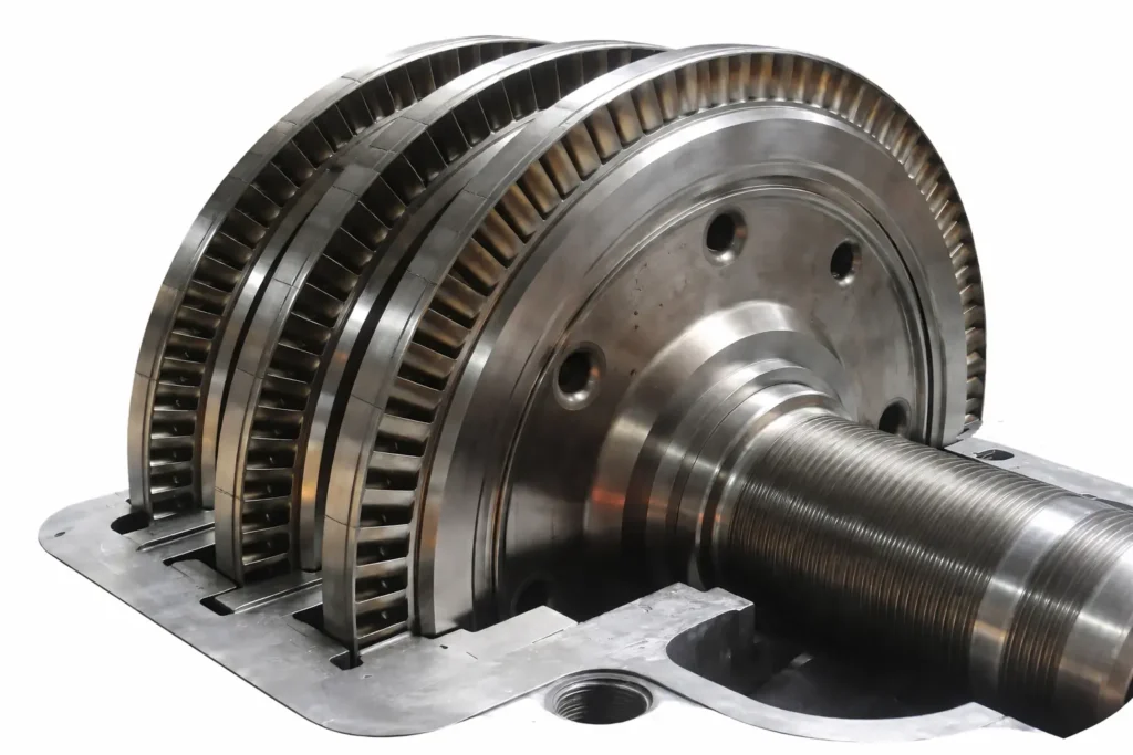
Elliott steam turbines, manufactured by Ebara Elliott Energy (Elliott Group), are industry-leading solutions for converting steam energy into reliable mechanical or electrical power. With over a century of engineering heritage, Elliott turbines are renowned for their rugged impulse design, high reliability in harsh environments, and adaptability across industrial applications ranging from oil & gas to power generation.
Key Product Lines
- Single-Stage YR Turbines The iconic YR series, with over 40,000 units installed worldwide, features single-valve impulse design and overhung rotors. Power range: 20 hp to approximately 5,400 hp (15–4,027 kW). Standardized frames (PYR to DYR) enable short lead times, with variants for condensing, back-pressure, and high back-pressure service.
- Multi-YR Turbines Hybrid multi-stage extension of the YR platform (2–9 impulse stages), delivering up to 14,000 hp (10,440 kW) with 15–30% improved efficiency. Offers drop-in retrofit capability using existing foundations and piping.
- Multi-Stage Turbines Custom multi-valve designs for outputs from 5,000 hp to over 175,000 hp (130 MW). Include condensing, extraction/induction, and high-speed configurations that eliminate gearboxes.
- Turbine-Generator Sets (STGs) Complete skid-mounted packages (50 kW–50 MW) for cogeneration, waste-heat recovery, and standalone power.
Design and Performance Features
- Impulse Blading: Primary energy transfer via momentum change, providing excellent wet-steam tolerance and low axial thrust.
- Materials and Construction: Chrome-moly casings, stainless steel blading, integrally forged rotors for durability.
- Efficiency: 70–80% (single-stage), up to 87%+ (multi-stage/Multi-YR).
- Controls: Digital governors with optional wireless monitoring for predictive maintenance.
- Standards: API 611/612 compliant for process-critical service.
Primary Applications
- Mechanical drives: Compressors, pumps, fans in refineries, petrochemical plants, and gas processing.
- Cogeneration and CHP: Simultaneous power and process steam supply.
- Renewable/waste heat: Biomass, geothermal, industrial recovery systems.
- Traditional industries: Pulp & paper lineshafts, sugar mill tandems.
Elliott turbines excel in continuous-duty environments requiring long service life (often 30–50 years), operational flexibility, and minimal maintenance. Their combination of standardization for rapid delivery and custom engineering for specific steam conditions makes them a preferred choice for energy efficiency and reliability in industrial process plants worldwide.
Elliott Steam Turbine – High-Efficiency Steam Power Solutions
Elliott’s commitment to high-efficiency steam power extends beyond core design to comprehensive system integration and ongoing performance optimization, ensuring plants extract maximum value from available steam resources.
Advanced Efficiency Enhancements
- Aerodynamic Refinements Continuous improvements in nozzle and blade profiling using computational tools reduce losses from incidence, separation, and secondary flows. Shrouded blade tips and precise tip clearances further minimize leakage, adding several percentage points to stage efficiency.
- Variable Geometry Options Select models incorporate adjustable nozzle groups or inlet guide vanes for better part-load performance, maintaining high efficiency during off-design operation common in process plants.
- Heat Rate Optimization In turbine-generator applications, careful matching of steam conditions to cycle requirements—combined with low exhaust losses in condensing designs—yields competitive heat rates for industrial-scale power production.
- Auxiliary System Efficiency Integrated lube oil consoles with variable-speed pumps and optimized cooling reduce parasitic power consumption. Digital controls enable automated startup/shutdown sequences that minimize energy waste during transients.
Performance Across Operating Ranges
Elliott turbines maintain strong efficiency even under variable conditions:
- Part-Load Operation: Robust impulse staging and precise governing prevent sharp efficiency drop-off at reduced loads.
- Overload Capability: Hand valves or sequential valve operation allow temporary power increases without excessive efficiency penalty.
- Steam Quality Variations: Tolerance to wetness or superheat fluctuations preserves performance where other designs might suffer erosion or flow disruption.
Sustainability and Energy Transition Support
High-efficiency designs directly contribute to reduced environmental impact:
- Lower specific steam consumption decreases fuel use in boilers
- Better waste-heat utilization improves overall plant energy balance
- Compatibility with renewable steam sources (biomass, solar thermal, geothermal) supports decarbonization
- Reduced auxiliary power lowers total plant emissions
Service Solutions for Sustained Efficiency
Elliott’s global support network helps operators maintain peak performance throughout the turbine lifecycle:
- Rerates and Upgrades: Blade path modifications, seal replacements, and control modernizations restore or exceed original efficiency.
- Predictive Maintenance: Wireless sensors monitor vibration, temperature, and alignment to prevent degradation.
- Performance Audits: On-site testing and analysis identify opportunities for improvement.
Elliott high-efficiency steam power solutions combine practical industrial engineering with targeted thermodynamic optimization. By delivering competitive efficiency within a package built for real-world reliability and long service life, Elliott turbines enable plants to minimize energy costs, maximize output from available steam, and meet increasingly stringent environmental requirements—all while maintaining the operational uptime that process industries demand.
Elliott Steam Turbine – Comprehensive Technical Overview
Elliott steam turbines stand as a benchmark for industrial steam power technology, blending proven impulse design principles with continuous refinements to deliver reliable, efficient, and adaptable performance across a broad spectrum of applications.
Fundamental Design Philosophy
Elliott turbines are built on a consistent impulse-stage foundation:
- Pure Impulse Operation: Pressure drop occurs almost entirely in stationary nozzles, producing high-velocity jets that transfer energy to moving blades via momentum change. This eliminates significant pressure differential across rotating blades, resulting in low axial thrust and superior tolerance to wet steam and contaminants.
- Rateau Pressure Compounding: In multi-stage units, the total enthalpy drop is distributed across multiple wheels, enabling moderate per-stage velocities and optimal blade-speed ratios for high work extraction.
- Conservative Mechanical Design: Generous safety margins, heavy-duty casings, and robust rotor construction prioritize long-term integrity over marginal efficiency gains achievable in more delicate designs.
Detailed Component Engineering
- Rotors: Single-stage YR models use built-up construction with induction-heated wheel fits; multi-stage units feature integrally forged rotors from high-alloy steels, eliminating shrunk-on disc risks.
- Blading: Stainless steel impulse buckets with optimized inlet/exit angles and shrouded tips to reduce leakage. Profiles refined through extensive testing and computational analysis.
- Nozzles and Diaphragms: Precision-machined for uniform flow distribution and minimal losses; materials selected for erosion resistance.
- Bearings: Tilt-pad journal and thrust designs with forced lubrication, providing excellent stability across speed and load ranges.
- Seals: Labyrinth standard; advanced carbon ring or brush seal options for applications requiring minimal leakage.
- Casings: Horizontally split for full access; high-pressure sections cast or fabricated from chrome-moly alloys, with separate exhaust casings to accommodate thermal expansion.
Control and Safety Systems
- Governing: Electronic digital systems with precise speed and load control; capable of handling rapid transients common in mechanical drive service.
- Safety Features: Overspeed trips, emergency stop valves, and modern partial-stroke testing capabilities for trip valve verification without shutdown.
- Monitoring: Optional wireless sensors for real-time vibration, temperature, and alignment data, enabling predictive maintenance strategies.
Performance Characteristics
- Power Range: From 20 hp single-stage units to multi-stage configurations exceeding 175,000 hp (130 MW).
- Steam Conditions: Inlet up to 2,000 psig (138 barg) and 1,005°F (541°C); exhaust from deep vacuum to high back-pressure.
- Efficiency: 70–80% isentropic in single-stage; 80–87%+ in multi-stage and Multi-YR designs—highly competitive for industrial scales.
- Speed Flexibility: 3,000–20,000 rpm, with high-speed options eliminating gearboxes for reduced losses and footprint.
Manufacturing and Quality Processes
Elliott maintains dedicated facilities emphasizing precision and consistency:
- Advanced CNC machining and high-speed balancing
- Comprehensive non-destructive testing
- Mechanical run testing under operating conditions
- String testing for complete assemblies where required
Standardized components across the YR family ensure rapid production and global parts availability.
Global Applications and Proven Performance
Elliott turbines serve as critical drivers and power sources in:
- Oil & gas production and processing
- Refining and petrochemical complexes
- Chemical and fertilizer manufacturing
- Pulp & paper production
- Sugar processing
- Cogeneration and waste-heat recovery systems
- Renewable steam applications
Their ability to operate continuously for decades in challenging conditions—often with availability exceeding 99%—has established Elliott as the preferred choice for applications where reliability directly impacts plant profitability and safety.
Elliott steam turbines continue to evolve through targeted engineering advancements, maintaining their position as robust, efficient, and field-proven solutions for industrial steam power requirements worldwide.
Elliott Steam Turbine – Reliability and Longevity in Industrial Service
One of the defining characteristics of Elliott steam turbines is their exceptional reliability and extended service life, making them a preferred choice for applications where unplanned downtime carries significant economic or operational consequences.
Factors Contributing to Superior Reliability
- Impulse Design Advantages The pure impulse staging places the primary pressure drop and velocity increase in stationary nozzles, shielding rotating blades from high-velocity droplet impacts in wet steam. This dramatically reduces erosion on critical rotating components, a common failure mode in other designs.
- Conservative Engineering Margins Rotors, casings, and bearings are designed with substantial safety factors against creep, fatigue, and overspeed. Critical speeds are positioned well away from operating ranges, and vibration damping is inherent in the heavy rotor and tilt-pad bearing configuration.
- Robust Materials Selection High-alloy steels for rotors, chrome-moly casings, and stainless steel blading resist corrosion, erosion, and thermal stress. Materials are chosen for proven performance rather than extreme temperature capability that might compromise long-term integrity.
- Simple Mechanical Architecture Fewer moving parts, horizontal casing splits for full access, and overhung rotor designs in single-stage units simplify inspections and repairs. There are no complex balance pistons or high-thrust configurations requiring delicate alignment.
- Proven Governance and Protection Mechanical-hydraulic or digital governors provide precise speed control, while independent overspeed trips and emergency stop valves ensure rapid, reliable shutdown in fault conditions.
Demonstrated Longevity in Service
Many Elliott turbines achieve extraordinary operating hours:
- Single-stage YR units commonly exceed 200,000–300,000 operating hours (equivalent to 30–40 years of continuous duty) with only routine maintenance.
- Multi-stage turbines in refinery and petrochemical service frequently operate 20–30 years between major overhauls.
- Installations in sugar mills and pulp & paper plants run seasonal campaigns year after year for decades in humid, contaminant-laden environments.
Maintenance and Uptime Characteristics
- Low Routine Maintenance Requirements Typical intervals include oil changes, filter replacements, and bearing inspections every 1–3 years. Major inspections (casing opening, rotor examination) are often scheduled every 8–12 years.
- High Availability Availability rates routinely exceed 98–99% in well-maintained installations, critical for process plants where turbine downtime halts entire production trains.
- Rapid Repair Capability Standardization across the YR family and stocked critical components enable fast turnaround for unplanned repairs.
Upgrade Paths for Extended Life
Rather than full replacement, Elliott offers:
- Multi-YR conversions that increase power and efficiency on existing foundations
- Blade and nozzle upgrades to restore or improve performance
- Control system modernizations adding digital monitoring and predictive capabilities
- Seal and bearing retrofits reducing leakage and vibration
These options allow plants to extend turbine life economically while gaining modern performance benefits.
Elliott steam turbines consistently deliver the reliability and longevity that industrial operators demand—operating decade after decade in the most challenging conditions with minimal intervention. This proven durability, combined with practical upgrade paths, provides exceptional lifecycle value and operational peace of mind for critical process applications worldwide.
Elliott Steam Turbine Capabilities for Global Industries
Ebara Elliott Energy (Elliott Group) provides comprehensive steam turbine capabilities that support critical operations across global industries. These turbines range from compact single-stage units to large multi-stage configurations, delivering reliable mechanical drive and power generation in diverse environments—from extreme cold to high humidity.
Core Capabilities Overview
- Power Range: 20 hp to over 175,000 hp (15 kW–130 MW), with turbine-generator sets up to 50 MW.
- Steam Conditions: Inlet up to 2,000 psig (138 barg) and 1,005°F (541°C); exhaust from vacuum to high back-pressure.
- Speed Range: Up to 20,000 rpm, including high-speed direct-drive options eliminating gearboxes.
- Design Standards: API 611/612 compliant; customizable for specific process needs.
- Global Manufacturing: Facilities in Jeannette (USA), Sodegaura (Japan), and Bengaluru (India), supporting regional production and service.
Elliott’s impulse-based designs prioritize reliability, wet-steam tolerance, and long service life, with over 40,000 YR units installed worldwide.
Key Industry Capabilities
- Oil & Gas Production and Processing High-speed turbines drive gas boosting, reinjection, and refrigeration compressors. Multi-stage units handle variable loads in upstream and midstream operations, including remote and offshore platforms.
- Refining and Petrochemical Turbines power cracked gas, propylene, ethylene, and synthesis gas compressors in large-scale plants. Elliott equipment supports nearly 50% of global ethylene capacity, with robust designs for high-pressure, high-temperature service in hydrocracking, reforming, and coking units.
- Chemical and Fertilizer Reliable drives for synthesis gas and circulation compressors in ammonia and fertilizer production. Extraction configurations optimize steam usage in integrated chemical complexes.
- Power Generation and Cogeneration Turbine-generator sets for combined heat and power (CHP), waste-to-energy, biomass, geothermal, and district heating. Solutions include condensing, back-pressure, and extraction turbines for efficient on-site power and process steam supply.
- Pulp & Paper Single-stage YR turbines drive high-speed paper machine lineshafts in humid, fiber-laden environments, often operating continuously for decades.
- Food Processing and Sugar YR turbines power cane shredders and mill tandems in seasonal campaigns, handling dusty, moist conditions with exceptional durability.
- Renewable and Green Energy Integration with waste heat recovery, biomass, geothermal, and solar thermal systems. Power recovery expanders and STGs reduce carbon footprint by converting waste energy to power.
- LNG and Cryogenic Applications Complementary capabilities with cryogenic pumps/expanders support liquefaction and regasification processes.
Global Service and Support Capabilities
Elliott’s network ensures sustained performance worldwide:
- Full-service repairs, rerates, and upgrades for Elliott and multi-OEM equipment
- Rapid spare parts supply through standardization
- Field service, training, and predictive monitoring
- Expanding facilities, including new centers for regional support
Elliott steam turbine capabilities address the evolving needs of global industries, providing rugged, efficient solutions that enhance productivity, reduce energy costs, and support sustainable operations in critical process and energy applications.
Elliott Steam Turbine – Innovation and Future Directions
Elliott continues to evolve its steam turbine technology to meet emerging industrial challenges, focusing on enhanced efficiency, digital integration, sustainability, and adaptability to new energy landscapes while preserving the core strengths of reliability and ruggedness.
Ongoing Technical Innovations
- Aerodynamic Improvements Continuous refinement of blade and nozzle profiles through advanced computational fluid dynamics and testing reduces losses and improves stage efficiency, particularly in multi-stage and Multi-YR configurations.
- High-Speed Technology Expansion of direct-drive designs eliminates gearboxes in more applications, reducing mechanical complexity, maintenance, and energy losses while enabling compact installations in space-constrained plants.
- Advanced Materials and Coatings Selective use of improved alloys and surface treatments enhances resistance to erosion, corrosion, and high-temperature creep, extending component life in aggressive steam environments.
- Digital Integration Wireless sensor packages and remote monitoring systems provide real-time data on vibration, temperature, and performance parameters. Integration with plant digital twins and predictive analytics helps operators anticipate maintenance needs and optimize operation.
Sustainability-Focused Developments
- Waste Heat and Low-Grade Steam Utilization Designs optimized for lower inlet temperatures and pressures enable greater recovery of industrial waste heat, improving overall plant energy efficiency and reducing carbon emissions.
- Renewable Steam Compatibility Turbines configured for biomass, geothermal, and concentrated solar thermal steam sources support the transition to renewable process heat and power generation.
- Efficiency Upgrades for Existing Fleets Multi-YR retrofits and blade path modernizations allow older installations to achieve significant steam savings, extending asset life while meeting modern environmental standards.
Service and Lifecycle Innovations
- Global Service Expansion Ongoing investment in regional service centers improves response times and local expertise for repairs, rerates, and upgrades.
- Multi-OEM Support Capabilities extended to service non-Elliott turbomachinery, providing comprehensive solutions for mixed fleets.
- Training and Knowledge Transfer Operator training programs and digital tools ensure plants maximize turbine performance and longevity.
Strategic Positioning
Elliott remains focused on the industrial segment, where its impulse-design advantages—wet-steam tolerance, operational forgiveness, and long service life—provide clear differentiation. Rather than competing in gigawatt-scale utility turbines, Elliott targets applications requiring robust performance under real-world process conditions.
By balancing continuous incremental innovation with unwavering commitment to proven engineering principles, Elliott steam turbines are well-positioned to support global industries through energy transitions, efficiency mandates, and evolving operational demands. The combination of field-tested reliability, practical efficiency improvements, and comprehensive lifecycle support ensures Elliott remains a trusted partner for critical steam power applications worldwide.
Elliott Steam Turbine – Global Service and Support Network
Elliott’s extensive global service and support infrastructure ensures that turbines deliver optimal performance throughout their long service lives, minimizing downtime and maximizing availability for operators worldwide.
Comprehensive Service Capabilities
- Field Service and Emergency Response Experienced technicians provide on-site support for installation, commissioning, troubleshooting, and emergency repairs. Rapid deployment teams address critical issues to restore operation quickly.
- Shop Repairs and Overhauls Dedicated repair facilities perform complete turbine overhauls, including rotor reblading, casing repairs, and component refurbishment. Capabilities extend to multi-OEM equipment, offering single-source solutions for mixed fleets.
- Rerates and Upgrades Engineering teams analyze existing installations and propose modifications—such as Multi-YR conversions, blade path upgrades, or control modernizations—to increase power, improve efficiency, or adapt to changing process conditions.
- Spare Parts Supply Extensive inventory of standardized components (particularly for the YR family) enables rapid global shipping. Critical parts are stocked strategically to meet urgent needs.
- Predictive and Condition-Based Maintenance Wireless monitoring systems and remote diagnostics allow real-time performance tracking. Data analytics identify emerging issues before they cause outages, shifting maintenance from scheduled to condition-based.
Regional Support Structure
Elliott maintains a network of service centers and partnerships covering key industrial regions:
- North America (primary facilities in Jeannette, Pennsylvania)
- Asia (Sodegaura, Japan, and Bengaluru, India)
- Middle East, Europe, and Latin America through dedicated shops and authorized partners
This structure provides localized expertise, reducing response times and logistics challenges for remote or offshore installations.
Training and Knowledge Transfer
- Operator and maintenance training programs at customer sites or Elliott facilities
- Digital resources and simulation tools for ongoing skill development
- Technical support hotlines for immediate engineering consultation
Lifecycle Partnership Approach
Elliott views service as a long-term partnership rather than transactional support:
- Long-term service agreements tailored to plant needs
- Performance audits to identify optimization opportunities
- Root cause analysis for recurring issues
- End-of-life planning and replacement strategies
This comprehensive approach ensures that Elliott turbines continue delivering value decades after initial installation. By combining rapid response capabilities with proactive maintenance tools and engineering expertise, Elliott’s global service network plays a crucial role in maintaining the high availability and efficiency that operators expect from their steam turbine investments.
Elliott’s service and support capabilities complement its engineering excellence, providing complete lifecycle management that maximizes return on investment and operational reliability for industrial steam power systems worldwide.
Elliott Steam Turbine: Industrial Power Generation Solutions
Elliott steam turbines provide robust, efficient solutions for industrial power generation, enabling on-site electricity production in process plants where reliable power, combined heat and power (CHP), or waste-heat utilization are essential. From small cogeneration systems to medium-scale standalone plants, Elliott turbines deliver dependable performance tailored to industrial needs.
Key Advantages for Industrial Power Generation
- High Reliability: Impulse design and conservative engineering ensure continuous operation with availability often exceeding 98–99%.
- Energy Efficiency: Optimized staging and modern controls maximize electrical output from available steam.
- Flexibility: Condensing, back-pressure, and extraction configurations support diverse plant requirements.
- Compact Packaging: Skid-mounted turbine-generator sets minimize installation time and footprint.
- Lifecycle Support: Global service network maintains performance over decades of service.
Turbine Solutions for Power Generation
- Turbine-Generator Sets (STGs) Complete, factory-assembled packages integrating turbine, gearbox (if required), generator, lubrication system, and controls on a single baseplate.
- Power range: 50 kW to 50 MW.
- Configurations: Induction or synchronous generators for grid-parallel or island-mode operation.
- Ideal for cogeneration, waste-heat recovery, and standalone industrial power supply.
- Condensing Turbines Maximize electrical output by expanding steam to vacuum exhaust.
- Suitable for facilities with cooling water availability and primary focus on power production.
- Often used in waste-heat recovery or renewable steam applications (biomass, geothermal).
- Back-Pressure (Non-Condensing) Turbines Exhaust steam at elevated pressure for direct process use (heating, drying, distillation).
- Optimal for plants requiring both electricity and thermal energy from the same steam source.
- Extraction and Induction Turbines Controlled steam extraction at intermediate pressures supplies process needs while maintaining power output.
- Single or double automatic extraction for precise steam flow matching.
- Induction options allow additional steam admission for peak loads.
- Multi-YR and Multi-Stage Generator Drives Higher-power solutions (up to 130 MW) for medium-scale industrial power plants or large cogeneration facilities.
Typical Industrial Power Generation Applications
- Cogeneration/CHP in Process Plants Simultaneous production of electricity and process steam improves overall energy utilization by 30–40% compared to separate generation.
- Waste-Heat Recovery Turbines convert recovered steam from industrial exhausts or incinerators into electricity, reducing purchased power costs.
- Renewable and Sustainable Power Integration with biomass boilers, geothermal fields, or solar thermal systems for carbon-neutral on-site generation.
- Remote or Island-Mode Facilities Reliable standalone power in locations with unstable grids or high electricity costs.
- District Heating Systems Back-pressure turbines supply both electricity and hot water/steam to nearby industrial or residential networks.
Performance and Integration Features
- Efficiency: Up to 87%+ isentropic in optimized configurations, delivering competitive heat rates for industrial scales.
- Rapid Startup: Mechanical design supports quick response to power demand changes.
- Digital Controls: Advanced governing and monitoring ensure stable operation and seamless grid synchronization.
- Compact Design: Reduced civil works and faster commissioning compared to large utility turbines.
Elliott industrial power generation solutions enable plants to achieve energy independence, reduce operating costs, and meet sustainability goals through efficient on-site electricity production. By leveraging available steam resources—whether from boilers, waste heat, or renewables—Elliott turbines provide practical, reliable power that integrates seamlessly with industrial processes while delivering long-term value and operational flexibility.
Elliott Steam Turbine – Sustainability and Energy Transition Support
Elliott steam turbines play a vital role in supporting industrial sustainability initiatives and the broader energy transition by maximizing energy utilization, reducing waste, and integrating with low-carbon steam sources.
Energy Efficiency Contributions
- Reduced Fuel Consumption High-efficiency designs—particularly Multi-YR and multi-stage configurations—lower specific steam rates, directly decreasing boiler fuel requirements and associated emissions for the same power output.
- Waste Heat Recovery Turbines optimized for low-grade steam enable recovery of thermal energy from industrial exhausts, incinerators, or process off-gases that would otherwise be lost. This improves overall plant energy balance and reduces reliance on primary fuel sources.
- Cogeneration Optimization Extraction and back-pressure turbines facilitate combined heat and power (CHP), achieving total energy utilization rates of 80–90% compared to 30–40% for separate heat and electricity production.
Integration with Renewable and Low-Carbon Sources
- Biomass and Waste-to-Energy Condensing or extraction turbines convert steam from biomass boilers or waste incineration into electricity and useful heat, supporting renewable power generation in industrial settings.
- Geothermal Applications Robust designs handle steam with high non-condensable gases and variable flow rates typical of geothermal fields, providing stable baseload renewable power.
- Solar Thermal Support Turbines integrate with concentrated solar power (CSP) systems using thermal storage, delivering dispatchable renewable electricity.
- Hydrogen and Future Fuels Materials and sealing systems compatible with emerging hydrogen-blended steam cycles position Elliott turbines for future low-carbon process heat applications.
Emissions Reduction Strategies
- Lower Carbon Intensity By generating on-site power from process steam or waste heat, plants reduce dependence on grid electricity—often produced from higher-emission sources.
- Process Optimization Precise steam extraction matching minimizes excess steam venting or throttling losses.
- Lifecycle Emissions Extended turbine life (30–50 years) and upgrade paths (e.g., Multi-YR retrofits) reduce the need for new equipment manufacturing and associated embodied carbon.
Practical Sustainability Benefits
- Regulatory Compliance Improved efficiency helps meet increasingly stringent energy intensity and emissions standards.
- Economic Incentives Higher energy utilization qualifies plants for efficiency credits, tax benefits, or carbon pricing advantages in many jurisdictions.
- Resource Conservation Reduced steam demand lowers water treatment and blowdown requirements.
Elliott’s focus on practical, field-proven efficiency improvements—rather than theoretical maximums achievable only in controlled conditions—ensures that sustainability benefits are realized in real industrial operations. By enabling plants to generate more power from less fuel, recover waste energy effectively, and integrate renewable steam sources, Elliott steam turbines provide tangible contributions to industrial decarbonization and sustainable energy management while maintaining the operational reliability that process industries require.
Elliott Steam Turbine – Manufacturing and Quality Assurance
Elliott’s manufacturing processes and quality assurance programs are integral to delivering turbines that consistently meet high standards of performance, reliability, and safety in industrial service.
Dedicated Manufacturing Facilities
Elliott operates specialized turbomachinery centers designed for precision production:
- Jeannette, Pennsylvania (USA): Primary headquarters and heavy-duty manufacturing site, handling complex multi-stage turbines, testing, and administration.
- Sodegaura, Japan: Advanced facility focused on high-precision components, R&D collaboration, and Asian market support.
- Bengaluru, India: Dedicated to standardized YR turbines and turbine-generator packages, enabling shorter lead times for regional customers.
These facilities are equipped with modern machinery and controlled environments to ensure component accuracy and consistency.
Precision Manufacturing Processes
- Material Procurement and Forging High-alloy steels are sourced to strict specifications. Rotors for multi-stage units are integrally forged, eliminating potential weak points from shrunk-on assemblies.
- Machining and Fabrication Computer numerical control (CNC) centers produce rotors, casings, diaphragms, and blading to tight tolerances. Horizontal boring mills and vertical turning lathes handle large components with precision.
- Blading and Assembly Blades are machined from stainless steel bars or forgings, with final profiling ensuring optimal aerodynamic performance. Rotors are assembled with induction heating for interference fits (single-stage) or integral construction (multi-stage).
- Balancing and Alignment High-speed dynamic balancing machines correct rotor unbalance to ISO standards. Overspeed spin testing verifies structural integrity.
Comprehensive Quality Assurance
- Non-Destructive Examination Ultrasonic, magnetic particle, radiographic, and dye penetrant testing identify internal or surface defects in critical components.
- Dimensional Inspection Coordinate measuring machines and laser alignment tools verify tolerances on rotors, casings, and assemblies.
- Mechanical Run Testing Every turbine undergoes no-load testing in dedicated bunkers, simulating operating conditions to confirm vibration levels, bearing performance, and governing response.
- Full-Load String Testing Larger units can be tested with driven equipment or load banks to validate performance across the operating envelope.
Documentation and Traceability
Full material certification, manufacturing records, and test data accompany each turbine, supporting compliance with customer specifications and regulatory requirements.
Elliott’s investment in manufacturing technology and rigorous quality processes ensures that turbines leaving the factory are built to perform reliably from day one and continue doing so for decades. This controlled production environment, combined with standardized designs and skilled craftsmanship, underpins the consistent quality and field-proven durability that define Elliott steam turbines in global industrial service.
Elliott Steam Turbine – Installation, Commissioning, and Startup Procedures
Elliott provides comprehensive guidance and support for the installation, commissioning, and startup of its steam turbines, ensuring safe, efficient integration into plant systems and rapid achievement of full operational capability.
Pre-Installation Planning
- Foundation Design Detailed drawings specify bolt patterns, centerline heights, and load distribution. Elliott engineers review site-specific conditions (soil, vibration, thermal expansion) to confirm foundation suitability.
- Piping and Auxiliary Layout Recommendations cover steam line sizing, drainage, flexibility for thermal growth, and isolation valves to minimize forces on turbine flanges.
- Alignment Considerations Provisions for precise coupling alignment, including laser tools and jacking points, are incorporated into baseplate designs.
Installation Process
- Baseplate and Grouting Skid-mounted packages arrive pre-aligned. Leveling pads and epoxy grouting ensure stable mounting and vibration isolation.
- Coupling and Driven Equipment Flexible couplings accommodate minor misalignment. Cold alignment checks precede hot alignment after initial run.
- Auxiliary Connections Lube oil consoles, turning gear, and instrumentation are connected per detailed schematics.
Commissioning Activities
- System Cleanliness Verification Steam line blowing or chemical cleaning removes debris that could damage blading. Elliott recommends strainer installation and inspection during this phase.
- Lube Oil System Flushing Oil is circulated through filters until cleanliness standards are met, protecting bearings from contaminants.
- Instrumentation Calibration Speed sensors, vibration probes, temperature thermocouples, and pressure transmitters are calibrated and loop-checked.
- Control System Testing Governor response, trip circuits, and alarm setpoints are verified through simulated signals.
Startup and Performance Validation
- Initial Slow Roll Turning gear operates continuously to prevent rotor sag during warmup. Steam admission begins at low flow for gradual heating.
- Critical Speed Passage Acceleration rates are controlled to minimize vibration during passage through rotor critical speeds.
- No-Load Mechanical Run Turbine reaches rated speed with steam conditions stabilized. Vibration, bearing temperatures, and governing stability are monitored.
- Load Acceptance Gradual loading confirms speed regulation and response to setpoints. For generator drives, synchronization and electrical checks follow.
- Performance Testing Optional acceptance tests measure power output, steam rates, and efficiency against guaranteed values.
Post-Startup Support
- Operator Training On-site sessions cover normal operation, emergency procedures, and basic troubleshooting.
- Performance Monitoring Baseline data is recorded for future comparisons during routine operation or audits.
Elliott’s structured approach to installation, commissioning, and startup minimizes risks and accelerates time to reliable production. Factory pre-assembly of packages, detailed manuals, and experienced field engineers ensure smooth transitions from delivery to full-load operation, contributing to the overall long-term success of turbine installations in industrial plants worldwide.
Elliott Steam Turbine – Maintenance and Troubleshooting Best Practices
Effective maintenance and proactive troubleshooting are key to maximizing the reliability, efficiency, and service life of Elliott steam turbines. Elliott provides detailed guidelines and support to help operators implement best practices tailored to industrial operating conditions.
Routine Maintenance Practices
- Daily and Weekly Checks Monitor oil levels, pressures, and temperatures; inspect for leaks, unusual noises, or vibration. Verify governor oil condition and drain condensates from steam lines and casings.
- Monthly and Quarterly Activities Sample and analyze lube oil for contamination, water, or degradation. Clean strainers and filters. Check coupling alignment and vibration trends using portable analyzers.
- Annual Inspections Perform borescope examinations of blading and internal passages without casing removal. Verify trip and throttle valve freedom of movement. Calibrate instrumentation and protective devices.
- Major Overhauls Typically scheduled every 8–12 years or 80,000–100,000 operating hours, depending on service severity. Involve casing opening, rotor removal, detailed NDE, blading inspection/replacement, and bearing renewal as needed.
Common Troubleshooting Areas
- Excessive Vibration Causes: Misalignment, unbalance, bearing wear, foundation issues, or steam-induced excitation. Resolution: Trend monitoring data, check alignment hot and cold, balance rotor if required, inspect bearings.
- High Bearing Temperatures Causes: Oil degradation, restricted flow, misalignment, or excessive loading. Resolution: Verify oil quality and flow, confirm alignment, check thrust bearing condition.
- Speed Control Issues Causes: Governor linkage wear, oil contamination, sensor drift, or valve sticking. Resolution: Clean and calibrate governor, inspect valves for deposits, verify feedback loops.
- Steam Leakage Causes: Worn labyrinth seals, carbon ring degradation, or gland steam pressure imbalance. Resolution: Adjust gland steam settings, replace seals during planned outages.
- Reduced Performance Causes: Fouling or erosion of blading, nozzle deposits, or increased internal clearances. Resolution: Performance testing to quantify loss, plan cleaning or blade path upgrade.
Preventive Strategies
- Oil System Cleanliness Maintain rigorous filtration and regular oil analysis to prevent bearing damage.
- Steam Purity Monitor for carryover of boiler water treatment chemicals or contaminants that cause deposits.
- Alignment Management Account for thermal growth with hot alignment checks after stable operation.
- Vibration Trending Use baseline data from commissioning for early detection of developing issues.
Documentation and Records
Operators should maintain comprehensive logs of:
- Operating hours and starts/stops
- Vibration and temperature trends
- Oil analysis results
- Maintenance actions and findings
Elliott’s maintenance recommendations balance scheduled activities with condition-based monitoring, allowing operators to optimize intervals based on actual service severity. This flexible approach, supported by detailed manuals and expert consultation, helps achieve the exceptional availability and extended service life that Elliott turbines are known for in industrial applications worldwide.
Elliott Steam Turbine: Manufacturing and Engineering Excellence
Elliott steam turbines exemplify manufacturing and engineering excellence through a combination of precision craftsmanship, rigorous quality processes, advanced design tools, and a century-long commitment to industrial reliability. This excellence ensures turbines perform consistently in demanding global applications while achieving long service lives and high operational availability.
Engineering Excellence
Elliott’s engineering approach balances innovation with proven principles:
- Impulse Design Mastery Decades of refinement in impulse blading, nozzle profiling, and Rateau pressure compounding deliver optimal energy transfer with minimal mechanical complexity. Modern computational fluid dynamics (CFD) and finite element analysis (FEA) optimize aerodynamics and structural integrity without compromising the design’s inherent robustness.
- Custom-Tailored Solutions While leveraging standardized frames (especially the YR series), engineers customize critical components—nozzles, blading, rotors, and casings—to match specific steam conditions, load profiles, and driven equipment requirements.
- Material and Process Expertise Selection of high-alloy steels, precise heat treatment, and advanced coatings ensure resistance to creep, corrosion, erosion, and thermal fatigue across extreme operating envelopes.
- System Integration Holistic design considers complete packages: lube systems, controls, turning gear, and coupling interfaces, ensuring seamless plant integration and minimal field adjustments.
Manufacturing Excellence
Elliott operates dedicated, state-of-the-art facilities focused exclusively on turbomachinery:
- Precision Machining Advanced CNC equipment produces components to micron-level tolerances. Vertical and horizontal turning centers, multi-axis milling machines, and specialized blade machining ensure dimensional accuracy critical for efficiency and balance.
- Component Fabrication Rotors are integrally forged or precisely assembled using induction heating for interference fits. Diaphragms and casings are machined from castings or forgings selected for metallurgical consistency.
- Assembly and Balancing Clean-room assembly environments prevent contamination. High-speed balancing bunkers correct rotor unbalance to stringent ISO standards, with overspeed testing verifying structural margins.
- Testing Regimen Every turbine undergoes comprehensive mechanical run testing: no-load operation at rated speed, vibration analysis, bearing temperature stabilization, and governor response verification. Larger units receive full-string load testing when required.
Quality Assurance Excellence
- Traceability and Documentation Full material certification and manufacturing records accompany each turbine, supporting compliance with customer specifications and international standards.
- Non-Destructive Examination Ultrasonic, magnetic particle, radiographic, and dye penetrant testing identify potential defects in critical components.
- Process Control ISO-certified quality management systems govern every production step, from incoming material inspection to final packaging.
Global Manufacturing Footprint
- Jeannette, Pennsylvania: Headquarters and center for complex multi-stage turbines and advanced testing.
- Sodegaura, Japan: High-precision manufacturing and collaborative R&D.
- Bengaluru, India: Focused production of standardized YR turbines and generator packages for regional markets.
This distributed yet coordinated approach ensures consistent quality while optimizing lead times and logistics for global customers.
Elliott’s manufacturing and engineering excellence manifests in turbines that not only meet specifications on delivery but continue performing reliably for decades in service. The integration of skilled craftsmanship, advanced technology, rigorous testing, and unwavering focus on industrial requirements establishes Elliott as a leader in delivering steam turbines that combine precision engineering with real-world durability and performance.
Elliott Steam Turbine – Safety Features and Protective Systems
Safety is a fundamental priority in Elliott steam turbine design, with multiple layers of protection engineered to prevent overspeed, mechanical failure, or operational hazards while ensuring rapid, reliable response in fault conditions.
Mechanical Safety Features
- Overspeed Trip System Independent mechanical-hydraulic or electronic overspeed detection triggers an emergency trip valve, closing steam admission in milliseconds. Setpoints are typically 110–115% of rated speed, with regular testing capability without full shutdown.
- Emergency Stop Valves Quick-closing valves in the steam inlet line provide redundant isolation. Designs include hydraulic or pneumatic actuation for fail-safe operation.
- Rotor Integrity Integrally forged rotors eliminate burst risks from shrunk-on discs. Overspeed spin testing during manufacturing verifies margins well above operating speeds.
- Thrust Bearing Protection Tilt-pad thrust bearings with high load capacity and collapse-type pads prevent damage during transients or loss of lubrication.
- Casing and Seal Design Heavy-duty casings withstand internal pressure excursions. Labyrinth and carbon ring seals minimize leakage while allowing controlled steam escape without catastrophic release.
Control and Monitoring Safety Systems
- Governor Stability Digital governors maintain precise speed control under normal and upset conditions, with bumpless transfer between modes.
- Vibration Monitoring Proximity probes on bearings continuously track shaft vibration. Alarms at warning levels and automatic trips at danger thresholds protect against unbalance or misalignment.
- Bearing Temperature Protection Embedded thermocouples or RTDs trigger alarms and trips if temperatures exceed safe limits, preventing seizure.
- Lube Oil System Safeguards Redundant pumps, accumulators, and low-pressure switches ensure continuous oil flow. Loss of oil pressure initiates immediate turbine trip.
Operational Safety Features
- Turning Gear Automatic or manual slow-roll during startup and shutdown prevents rotor bowing from thermal gradients.
- Partial Stroke Testing Modern trip valve systems allow periodic function testing without interrupting operation, verifying readiness while maintaining availability.
- Gland Steam System Controlled sealing steam prevents air ingress (fire risk) or excessive steam leakage to atmosphere.
Compliance and Testing
- Designs meet or exceed API 611/612, ASME, and international safety standards.
- Factory testing includes trip function verification and response time measurement.
- Field commissioning confirms full integration with plant emergency shutdown (ESD) systems.
Elliott’s multi-layered safety approach—combining mechanical robustness, redundant protection, and intelligent monitoring—ensures turbines operate safely even under upset conditions. This comprehensive protection minimizes risk to personnel, equipment, and production while supporting the high availability demanded in industrial processes. Regular testing and maintenance of these systems, guided by Elliott recommendations, maintain safety integrity throughout the turbine’s extended service life.
Elliott Steam Turbine – Comprehensive Lifecycle Management
Elliott provides end-to-end lifecycle management for its steam turbines, ensuring optimal performance from initial concept through decades of operation and eventual upgrade or decommissioning.
Pre-Sales and Design Phase
- Application Engineering Elliott collaborates closely with customers to define exact requirements: steam conditions, power output, driven equipment specifications, and operational profile. This leads to tailored designs that balance efficiency, reliability, and cost.
- Simulation and Modeling CFD for flow path optimization and FEA for structural analysis verify performance before manufacturing begins.
- Proposal and Contract Review Detailed specifications, performance guarantees, and risk assessments ensure alignment with customer expectations.
Manufacturing and Delivery Phase
- Quality and Testing Every turbine undergoes rigorous mechanical run testing, vibration analysis, and trip system verification.
- Documentation Package Comprehensive manuals, drawings, spare parts lists, and maintenance schedules accompany each unit.
Installation and Commissioning Phase
- Site Support Elliott field engineers oversee foundation alignment, piping connections, and auxiliary system integration.
- Startup Assistance Gradual loading, performance testing, and operator training ensure smooth transition to full operation.
Operational Phase
- Routine Maintenance Guidance Recommended schedules for inspections, oil analysis, and minor adjustments to prevent degradation.
- Performance Monitoring Digital tools track key parameters, identifying trends that may indicate emerging issues.
- Spare Parts and Logistics Global inventory and rapid shipping of standardized components minimize downtime.
Mid-Life and Upgrade Phase
- Rerate and Retrofit Multi-YR conversions and blade path upgrades increase power and efficiency on existing foundations.
- Modernization Control system upgrades, seal replacements, and bearing renewals restore or enhance original performance.
- Condition Assessment Non-destructive testing and borescope inspections during planned outages evaluate internal condition.
End-of-Life and Decommissioning Phase
- Life Extension Options When major overhaul costs approach replacement value, Elliott engineers assess feasibility of continued operation with targeted upgrades.
- Replacement Planning Seamless transition to new units, often with Multi-YR retrofits to minimize production disruption.
- Recycling and Disposal Guidance on responsible decommissioning and material recycling.
Elliott’s lifecycle management approach treats each turbine as a long-term asset, providing tailored support at every stage to maximize return on investment. This comprehensive strategy—combining engineering expertise, proactive service, and upgrade pathways—ensures turbines remain productive and efficient throughout their extended service lives, delivering sustained value to global industrial operators.
Elliott Steam Turbine Technology and Industrial Expertise
Ebara Elliott Energy (Elliott Group) stands as a global leader in steam turbine technology, with over a century of specialized expertise in designing, manufacturing, and servicing turbines for demanding industrial applications. Elliott’s technology focuses on impulse-based designs that prioritize rugged reliability, operational flexibility, and long-term performance in harsh environments, setting it apart in mechanical drive and medium-power generation sectors.
Core Technology and Design Expertise
Elliott turbines predominantly employ impulse blading with Rateau pressure compounding, where steam expands primarily in stationary nozzles to create high-velocity jets impacting curved rotor blades. This approach delivers:
- Excellent tolerance to wet steam and contaminants
- Low axial thrust for simpler bearing designs
- Robustness for continuous duty in variable conditions
Key product lines showcase this expertise:
- Single-Stage YR Series: Over 40,000 units installed; standardized for rapid delivery, with power up to ~5,400 hp and variants for high back-pressure service.
- Multi-YR Series: Hybrid multi-stage (2–9 stages) retrofit solution, increasing power to 14,000 hp and efficiency by 15–30% on existing foundations.
- Multi-Stage Turbines: Custom units up to 175,000 hp (130 MW), including high-speed gearbox-free models and extraction/induction configurations.
- Turbine-Generator Sets: Packaged systems up to 50 MW for cogeneration and waste-heat recovery.
Inlet conditions support up to 2,000 psig and 1,005°F, with speeds to 20,000 rpm and API 611/612 compliance.
Industrial Expertise and Applications
Elliott’s deep domain knowledge spans critical process industries:
- Oil & Gas/Petrochemical/Refining: Driving compressors in ethylene (supporting ~50% global capacity), hydrocracking, and gas processing; high-speed designs optimize compressor trains.
- Chemical/Fertilizer: Reliable drives for synthesis gas and circulation compressors.
- Pulp & Paper/Food Processing: Durable YR units for lineshafts and mill tandems in humid, dusty settings.
- Power and Renewables: Cogeneration, waste-heat recovery, biomass, and geothermal integration.
Recent advancements (as of late 2025) include the Eagle Series launched in May 2025 for small-scale industrial and waste-to-energy plants, offering up to 10% higher energy recovery in decentralized systems.
Manufacturing and Global Capabilities
Facilities in Jeannette (USA), Sodegaura (Japan), and Bengaluru (India) enable precision production of standardized and custom components. Expertise extends to cryogenic pumps/expanders and multi-OEM service.
Elliott’s industrial expertise—rooted in impulse technology refined over decades—delivers turbines that excel in real-world reliability, efficiency upgrades (via rerates/Multi-YR), and sustainability support (waste heat, renewables). This focused approach ensures exceptional performance in mechanical drives and distributed power, where operational uptime and adaptability drive plant success.
Elliott Steam Turbine – Global Impact and Legacy
Elliott steam turbines have left an indelible mark on global industry through decades of reliable service in critical applications, contributing to energy production, process efficiency, and industrial development worldwide.
Extensive Installed Base
- Over 40,000 single-stage YR turbines operate across continents, forming the backbone of mechanical drives in thousands of plants.
- Multi-stage and generator sets support major facilities in oil & gas, petrochemical, refining, chemical, power, and renewable sectors.
- Installations span diverse climates and conditions—from arctic pipelines to tropical sugar mills and desert refineries—demonstrating universal adaptability.
Contributions to Key Industries
- Energy Infrastructure: Enabling efficient power generation and cogeneration in facilities that supply electricity and process steam to millions.
- Petrochemical Growth: Supporting nearly half of global ethylene production capacity through reliable compressor drives in mega-plants.
- Food and Agriculture: Powering seasonal campaigns in sugar mills and continuous operations in food processing, contributing to global food supply chains.
- Resource Development: Driving gas reinjection and processing in remote oil & gas fields, enhancing recovery and extending field life.
Economic and Environmental Legacy
- Energy Conservation: High-efficiency designs and retrofits have saved countless tons of fuel over decades by reducing steam consumption in industrial processes.
- Sustainability Enablement: Early adoption in waste-heat recovery and biomass systems laid groundwork for modern renewable integration.
- Operational Continuity: Exceptional reliability has prevented major production losses in plants where turbine downtime would have severe economic consequences.
Enduring Engineering Legacy
- The YR series remains in production after more than 70 years, a testament to the timelessness of its fundamental design.
- Continuous evolution—Multi-YR retrofits, high-speed drives, digital monitoring—shows how core impulse principles adapt to modern requirements.
- Knowledge transfer through global service and training has built operator expertise across generations.
Elliott steam turbines represent more than equipment—they embody a legacy of engineering solutions that have powered industrial progress reliably and efficiently for over a century. From enabling major petrochemical expansions to supporting renewable transitions, Elliott technology continues to play a vital role in global energy and manufacturing infrastructure, delivering sustained value through innovation grounded in proven industrial expertise.
Elliott Steam Turbine – Training and Knowledge Transfer Programs
Elliott places strong emphasis on training and knowledge transfer to empower operators, maintenance personnel, and engineers with the skills needed to maximize turbine performance, safety, and longevity.
Operator Training Programs
- Basic Operation Covers daily startup/shutdown procedures, normal monitoring (vibration, temperatures, pressures), and response to common alarms. Focuses on safe steam admission, load changes, and emergency trip recognition.
- Advanced Operation Includes governor tuning, part-load optimization, and handling variable steam conditions. Participants learn to interpret performance trends and coordinate with plant control systems.
Maintenance Training Programs
- Preventive Maintenance Hands-on instruction in routine tasks: oil sampling/analysis, filter changes, alignment checks, and borescope inspections.
- Overhaul and Repair Detailed modules on major inspections, rotor removal, blading assessment, bearing replacement, and reassembly. Includes NDE interpretation and balance correction.
- Troubleshooting Systematic diagnosis of common issues—vibration, bearing temperatures, speed control problems, and leakage—using real case studies.
Engineering and Technical Training
- Design and Performance In-depth sessions on impulse blading mechanics, thermodynamic principles, and efficiency optimization for plant engineers.
- Retrofit and Upgrade Planning Guidance on evaluating Multi-YR conversions, rerates, or control modernizations to meet changing plant needs.
Delivery Formats
- On-Site Training Customized sessions at customer facilities using the installed turbine for practical demonstrations.
- Factory-Based Training Held at Elliott facilities with access to test stands, cutaway models, and disassembly demonstrations.
- Digital and Remote Options Web-based modules, virtual reality simulations, and remote instructor-led courses for ongoing skill development.
Supporting Resources
- Comprehensive operation and maintenance manuals with detailed procedures and diagrams
- Digital troubleshooting guides and performance calculators
- Access to technical support specialists for post-training consultation
Elliott’s training programs are designed to build self-sufficiency while fostering long-term partnerships. By transferring deep product knowledge and best practices, Elliott ensures that operators worldwide can achieve the high availability, efficiency, and safety that its turbines are capable of delivering throughout their extended service lives. This commitment to education reinforces the overall value of Elliott steam turbine investments in global industrial operations.
Elliott Steam Turbine – Performance Monitoring and Optimization
Elliott equips its steam turbines with advanced monitoring capabilities and provides tools for ongoing performance optimization, enabling operators to maintain peak efficiency and detect issues early in industrial operating environments.
Built-In Monitoring Systems
- Vibration Monitoring Proximity probes on bearings continuously measure shaft vibration. Baseline data from commissioning establishes normal levels, with alarms for increases indicating unbalance, misalignment, or bearing wear.
- Temperature Monitoring Embedded RTDs or thermocouples track bearing metal temperatures, oil sump, and drain conditions. Trends help identify oil degradation, restricted flow, or overload.
- Speed and Load Sensing Magnetic pickups or encoders provide precise speed feedback for governing and overspeed protection.
- Pressure and Flow Instruments Inlet/exhaust pressure and temperature transmitters enable real-time calculation of power output and efficiency.
Advanced Digital Options
- Wireless Sensor Packages Battery-powered or energy-harvesting sensors transmit vibration, temperature, and alignment data remotely, ideal for hard-to-access installations.
- Remote Diagnostics Secure data connectivity allows Elliott experts to review trends and recommend actions without site visits.
- Performance Calculation Tools Software integrates sensor data to compute steam rates, isentropic efficiency, and heat rate, comparing against design curves.
Optimization Practices
- Baseline Establishment Comprehensive acceptance testing during commissioning records initial performance for future comparisons.
- Trend Analysis Regular review of logged data identifies gradual degradation from fouling, erosion, or seal wear.
- Efficiency Audits Periodic on-site or remote assessments quantify losses and recommend corrective actions such as cleaning, seal upgrades, or blade path modifications.
- Load Optimization Guidance on operating at most efficient steam conditions or valve positions for prevailing loads.
Benefits of Proactive Monitoring
- Early detection prevents minor issues from becoming major failures
- Scheduled maintenance replaces calendar-based overhauls
- Sustained efficiency minimizes fuel costs and emissions
- Extended component life through timely interventions
Elliott’s performance monitoring and optimization capabilities transform turbines from static equipment into actively managed assets. By combining robust built-in instrumentation with modern digital tools and expert support, operators can maintain near-design performance throughout the turbine’s long service life, maximizing return on investment and operational reliability in demanding industrial applications.
Elliott Steam Turbine Production and Performance Standards
Elliott steam turbines are produced with rigorous adherence to international industry standards, ensuring consistent quality, safety, reliability, and performance in demanding industrial applications. Manufacturing emphasizes precision, traceability, and testing to meet or exceed customer specifications.
Key Production Standards
- ISO 9001 Certification Elliott’s primary manufacturing facilities in the USA and Japan maintain quality management systems certified to ISO 9001. This standard governs design, production, inspection, and continuous improvement processes.
- ASME Certifications Accredited with ASME U (pressure vessel) and R (repair) stamps for boiler and pressure vessel compliance.
- Non-Destructive Examination (NDE) Personnel qualified per ASNT SNT-TC-1A guidelines. Techniques include ultrasonic, magnetic particle, radiographic, and dye penetrant testing for critical components like rotors and casings.
- Welding Qualifications Welders certified to ASME Section IX standards.
- Project-Specific Compliance Turbines can meet additional standards such as ANSI, CRN (Canadian Registration Number), CSA, and CE/PED (European Pressure Equipment Directive) as required.
Performance and Design Standards
- API Compliance
- API 611: Applies to general-purpose steam turbines (typically smaller, non-critical service). Elliott single-stage YR turbines and many general-purpose units meet or exceed API 611 requirements.
- API 612: For special-purpose steam turbines (critical, high-power applications). Elliott multi-stage, high-speed, and refinery-service turbines are designed to API 612, including features like solid forged rotors, advanced sealing, and enhanced testing.
- NEMA Specifications For turbine-generator sets, compliance with NEMA SM-23 and SM-24 (steam turbines for mechanical drive) when specified.
- Performance Guarantees Elliott provides contractual guarantees for power output, steam consumption (specific steam rate), efficiency, and vibration levels under specified conditions. Acceptance testing during commissioning verifies these parameters.
Production Processes Supporting Standards
- Material Traceability: Full certification from forging to finished component.
- Precision Manufacturing: CNC machining ensures tight tolerances for aerodynamic efficiency and mechanical balance.
- Testing Protocols:
- Dynamic balancing to ISO standards
- No-load mechanical run tests for vibration, bearing performance, and governing
- Optional full-load string testing for large units
- Overspeed spin testing for rotors
These standards and processes ensure Elliott turbines deliver predictable performance, with efficiencies up to 87%+ in multi-stage designs and proven longevity in service. Compliance facilitates integration into regulated industries like oil & gas and petrochemicals, while supporting global operability and lifecycle reliability.
Elliott Steam Turbine – Research and Development Focus
Elliott invests continuously in research and development to advance steam turbine technology while staying true to its core strengths of reliability, efficiency, and industrial applicability.
Key R&D Priorities
- Aerodynamic Optimization Ongoing refinement of blade and nozzle profiles using advanced computational fluid dynamics (CFD) and flow visualization techniques. Focus on reducing secondary losses, improving part-load efficiency, and minimizing erosion in wet-steam conditions.
- Materials Advancement Evaluation of new alloys and coatings for enhanced resistance to high-temperature creep, corrosion, and erosion. Development of surface treatments that extend component life in aggressive steam environments.
- High-Speed Technology Expansion of direct-drive capabilities to higher power levels, eliminating gearboxes and associated losses while maintaining rotor dynamic stability.
- Digital and Predictive Technologies Development of wireless sensor systems, edge computing for real-time analytics, and integration with plant digital twins. Emphasis on algorithms that predict maintenance needs and optimize operation under varying loads.
- Efficiency Enhancement Packages Research into retrofit solutions like Multi-YR conversions and advanced sealing systems that deliver measurable steam savings on existing installations.
Sustainability-Driven Research
- Low-Grade Steam Utilization Designs for turbines operating efficiently with lower inlet temperatures and pressures, enabling greater waste-heat recovery.
- Renewable Integration Adaptation for variable steam flows from biomass, geothermal, and solar thermal sources.
- Emissions Reduction Studies on cycle improvements that minimize fuel use and support carbon capture compatibility.
Collaborative Approach
- Partnerships with customers for field testing of new concepts
- Cooperation with research institutions on fundamental turbomachinery topics
- Internal test facilities for component validation under controlled conditions
Elliott’s R&D strategy emphasizes practical, incremental advancements that deliver tangible benefits in real industrial operating environments rather than theoretical breakthroughs suited only to laboratory conditions. This focused approach ensures that new developments enhance the proven reliability and longevity that define Elliott turbines while addressing evolving customer needs for efficiency, sustainability, and digital integration. The result is a technology portfolio that continues to evolve purposefully, maintaining Elliott’s leadership in industrial steam power solutions.
Elliott Steam Turbine – Customer Success Stories and Testimonials
Elliott steam turbines have earned widespread acclaim from operators across industries for their reliability, performance improvements, and lifecycle value. While specific client names are often confidential, representative feedback and success metrics from various installations highlight the real-world impact of Elliott technology.
Long-Term Reliability Feedback
Operators frequently report YR turbines operating continuously for 30–50 years with only routine maintenance. In pulp & paper and sugar mill applications, users note consistent performance through hundreds of seasonal campaigns in challenging environments, with availability rates routinely above 99%.
Efficiency Upgrade Success
Plants implementing Multi-YR retrofits commonly achieve 20–30% reductions in specific steam consumption while increasing driver power significantly. Feedback emphasizes the minimal downtime during conversion and rapid return on investment through lower energy costs.
Cogeneration and Power Generation
Facilities using Elliott turbine-generator sets praise the seamless integration and stable output in CHP systems. Users highlight improved overall energy utilization (often 80–90%) and reduced dependence on grid power, contributing to both cost savings and sustainability goals.
Mechanical Drive Performance
In oil & gas and petrochemical compressor trains, operators value the high-speed designs for eliminating gearboxes and the impulse blading for handling variable steam quality without erosion issues. Long-running installations report over 150,000 operating hours with original blading intact.
Service and Support Appreciation
Customers consistently commend Elliott’s global service network for rapid response, expert troubleshooting, and effective rerates that extend turbine life economically. The availability of standardized parts and knowledgeable field engineers is frequently cited as a key factor in maintaining high plant availability.
Overall Operator Sentiment
Across sectors, common themes in feedback include:
- Exceptional durability compared to competing designs
- Measurable reductions in operating costs through efficiency gains
- Confidence in uninterrupted production due to proven uptime
- Strong partnership with Elliott for ongoing support and upgrades
These success stories reflect Elliott’s focus on delivering practical, field-proven solutions that address real industrial challenges. The combination of robust engineering, targeted performance improvements, and dedicated lifecycle support continues to build lasting trust with operators worldwide, reinforcing Elliott’s reputation as a reliable partner in steam power technology.
Elliott Group has established itself as a global leader in the design and manufacture of highly engineered steam turbines. These systems are engineered to provide maximum reliability and efficiency across a diverse spectrum of industrial applications, ranging from small mechanical drives to large-scale power generation. With a legacy spanning over a century, Elliott steam turbines are designed to meet rigorous industry standards, including API 611 and API 612.
Product Range and Technical Capabilities
Elliott offers a comprehensive portfolio of steam turbines tailored to specific operational requirements. The power range extends from small 20 HP (15 kW) units to massive multi-stage configurations delivering up to 175,000 HP (130,000 kW).
Single-Stage Steam Turbines (YR Series)
The YR series represents the industry standard for single-stage turbines, with over 35,000 units installed worldwide. These turbines are prized for their ruggedness and adaptability in driving pumps, fans, and compressors.
- Power Output: Up to 3,500 HP (2,600 kW).
- Inlet Conditions: Pressures up to 900 psig (62 barg) and temperatures up to 900°F (482°C).
- Design Features: Horizontal split casings for ease of maintenance, interchangeable wearing parts, and true centerline support to maintain alignment across thermal cycles.
Multi-Stage and Multi-Valve Turbines
For applications requiring higher efficiency and greater power, Elliott’s multi-stage turbines offer advanced aerodynamic designs and precise control.
- Configurations: Available in condensing, non-condensing (back-pressure), extraction, and induction models.
- Speed Range: Capable of operating at speeds up to 20,000 rpm, often eliminating the need for a gearbox in high-speed compressor drives.
- Efficiency: Multi-valve designs utilize bar/cam lift mechanisms to maintain high efficiency even at partial loads by accurately throttling steam flow.
Core Engineering Components
The technical superiority of an Elliott turbine is found in its structural integrity and precision-engineered internals.
- Rotors: Multistage units feature solid-forged rotor construction, machined from alloy steel forgings. This design ensures stability at high speeds and minimizes residual stresses. Every rotor undergoes dynamic balancing at actual operating speeds.
- Casing Design: Constructed with heavy-duty horizontal split casings, these units allow for easy access to the rotor and internal components without disconnecting the main steam piping.
- Bearings and Seals: High-performance tilt-pad journal bearings are used to ensure rotor stability. For shaft sealing, Elliott utilizes engineered labyrinth seals or specialized gas face seals to minimize steam leakage and prevent oil contamination.
- Diaphragms and Nozzles: Nozzle rings are precision-milled from stainless steel to optimize steam flow paths and maximize energy transfer to the turbine blades.
Safety and Control Systems
Modern Elliott turbines are equipped with sophisticated digital control systems that integrate seamlessly with plant-wide Distributed Control Systems (DCS).
- Digital Governors: Elliott Digital Governors (EDG) provide precise speed and extraction control, ensuring stable operation under fluctuating load conditions.
- Pos-E-Stop System: A patented emergency trip system featuring the 203 Trip Block. It utilizes triple-redundant solenoid valves to provide a “two-out-of-three” logic for emergency shutdowns, allowing for online testing and maintenance without compromising the safety margin.
- Steam End Flexibility: Configurations can include automatic extraction/induction, allowing plants to balance process steam demand with electrical power generation effectively.
Strategic Industrial Applications
Elliott’s industrial steam solutions are deployed in critical environments globally, including:
- Oil & Gas Refining: Driving large cracked-gas and process compressors.
- Petrochemical Processing: Providing reliable mechanical power for high-speed machinery.
- Power Generation: On-site Steam Turbine Generators (STG) for cogeneration and renewable energy initiatives like biomass and geothermal.
- Manufacturing: Powering shredders in sugar mills and line shafts in paper mills.
The Elliott Group has long served as a cornerstone of industrial machinery, specializing in highly engineered steam turbines that provide reliable mechanical drive and power generation solutions for the world’s most demanding environments. These systems are designed with a focus on structural integrity and thermodynamic efficiency, meeting the rigorous standards of API 611 and API 612. The engineering philosophy behind Elliott steam turbines centers on versatility and longevity, allowing them to operate in extreme conditions ranging from the sub-zero temperatures of arctic regions to the high-humidity, corrosive atmospheres of tropical petrochemical complexes. By utilizing advanced materials and precision manufacturing, Elliott ensures that each turbine unit can withstand the thermal stresses associated with rapid startup and cycling while maintaining tight tolerances in the internal steam path.
At the heart of Elliott’s mechanical drive capabilities is the YR series of single-stage turbines, which are recognized globally for their ruggedness and ease of maintenance. These units feature a horizontal split-casing design, which allows for internal inspections and repairs without the need to disturb the main steam piping or the foundation of the unit. The rotors are typically built with high-strength alloy steels and are precision balanced to minimize vibration and extend the life of the bearings. In many applications, these turbines serve as the primary drivers for pumps, fans, and small compressors, often replacing electric motors in facilities where process steam is readily available, thereby improving the overall thermal efficiency of the plant by utilizing waste heat or high-pressure steam before it enters a process header.
For larger-scale industrial needs, Elliott’s multi-stage and multi-valve turbines provide a more sophisticated solution capable of generating massive amounts of horsepower or electricity. These turbines incorporate advanced aerodynamic blade profiles and intricate nozzle designs to extract the maximum amount of kinetic energy from the expanding steam. Multi-valve configurations allow for better control and efficiency at partial load conditions by sequentially opening and closing valves to regulate steam flow, preventing the throttling losses typically associated with single-valve designs. These units are often configured for extraction or induction, allowing a facility to bleed off steam at specific pressures for downstream processes or to inject low-pressure waste steam back into the turbine to boost power output, providing a flexible and integrated energy management solution.
The reliability of these systems is further enhanced by Elliott’s specialized auxiliary components, including their proprietary digital control systems and safety mechanisms. The Pos-E-Stop system, for example, represents a critical advancement in turbine safety, providing a trip block that ensures rapid and reliable shutdown in the event of an overspeed or other critical fault. Furthermore, the use of tilt-pad journal bearings and advanced sealing technologies, such as carbon rings or labyrinth seals, minimizes friction and prevents steam leakage, which is essential for maintaining a clean and safe operating environment. Through a combination of robust mechanical design and modern digital monitoring, Elliott steam turbines provide a comprehensive solution that addresses the modern industrial need for continuous operation, energy conservation, and safety.
The Elliott Group has established an unparalleled reputation in the field of industrial turbomachinery by focusing on the precise intersection of thermodynamic efficiency and mechanical durability. The fundamental design of an Elliott steam turbine begins with the casing, which is engineered to handle extreme pressure differentials while maintaining axial and radial alignment under varying thermal loads. In high-pressure applications, these casings are often constructed from cast steel or specialized alloys that resist creep and deformation at elevated temperatures. The horizontal split-line design is a hallmark of Elliott engineering, allowing the upper half of the casing to be removed for maintenance without disturbing the critical alignment of the turbine to its driven equipment. This design philosophy extends to the internal components, where the steam path is meticulously contoured to reduce turbulence and maximize the transition of thermal energy into rotational kinetic energy.
The rotor assembly is perhaps the most critical component within the turbine, acting as the primary vehicle for power transmission. Elliott rotors are typically machined from high-quality alloy steel forgings, ensuring a homogenous grain structure that can withstand the centrifugal forces generated at speeds exceeding 15,000 revolutions per minute. The turbine blades, or buckets, are attached to the rotor disks using various methods such as pine-tree or dovetail roots, which are designed to distribute mechanical stress evenly. These blades are often manufactured from stainless steel or specialized superalloys to resist the erosive effects of moisture droplets in the exhaust stages and the corrosive nature of steam impurities. The aerodynamic profile of each blade is optimized through computational fluid dynamics to ensure that steam expansion occurs as close to an isentropic process as possible, thereby maximizing the overall efficiency of the machine.
In addition to the rotor and casing, the diaphragm and nozzle assemblies play a vital role in directing steam flow. Each stage of a multi-stage Elliott turbine consists of a stationary diaphragm that houses the nozzles and a rotating disk. The nozzles are designed to accelerate the steam to high velocities before it impacts the rotating blades. Precision-milled nozzle rings allow for exact control over the angle of entry, which is crucial for minimizing “shock” losses and maintaining smooth operation across a wide range of steam conditions. In multi-valve turbines, the steam chest contains several independent valves that are controlled by a cam-lift mechanism. This allows the turbine to maintain high efficiency at partial loads because the steam is not throttled through a single large valve, which would cause a significant drop in pressure and energy potential. Instead, valves are opened sequentially to meet the specific power requirements of the driven compressor or generator.
The management of steam leakage is handled through a series of engineered seals, primarily using labyrinth or carbon ring technology. Labyrinth seals consist of a series of sharp-edged fins that create a difficult path for steam to escape, utilizing the principle of pressure breakdown across each tooth. In many modern Elliott designs, these are supplemented by steam seal systems that maintain a slight positive pressure of sealing steam, ensuring that no atmospheric air enters the condensing stages and no process steam escapes into the bearing housings. This is particularly important in condensing turbine applications where maintaining a high vacuum in the exhaust casing is essential for maximizing the pressure drop across the turbine, which directly correlates to the amount of work the turbine can perform.
Bearing technology in Elliott turbines is designed to ensure stable operation and longevity. Most units utilize tilt-pad journal bearings, which are self-aligning and provide excellent damping characteristics against oil film whirl and other rotor-dynamic instabilities. These bearings are lubricated by a pressurized oil system that not only reduces friction but also carries away the heat generated by high-speed rotation and thermal conduction from the steam path. Thrust bearings, typically of the Kingsbury or similar tilt-pad design, are employed to manage the axial forces generated by the steam as it pushes against the rotor stages. These systems are often monitored by proximity probes and thermocouples that provide real-time data to the plant’s control room, allowing for predictive maintenance and immediate intervention if vibration or temperature limits are exceeded.
Beyond the mechanical hardware, the integration of advanced control systems has transformed the Elliott steam turbine into a highly responsive and intelligent asset. The Elliott Digital Governor (EDG) manages the speed and load of the turbine with micro-second precision, coordinating with the plant’s distributed control system to respond to changes in process demand. For turbines involved in cogeneration or “combined heat and power” (CHP) applications, the controls manage extraction and induction points. This means the turbine can provide a constant flow of steam to a secondary industrial process, such as heating or chemical reaction, while simultaneously fluctuating its power output to meet electrical demands. This dual-purpose functionality is a key driver for the adoption of Elliott turbines in the pulp and paper, sugar, and petrochemical industries, where steam is used both as a source of power and a direct process utility.
Safety remains the highest priority in the design of Elliott industrial solutions. The emergency overspeed trip system is a stand-alone safety layer that functions independently of the primary speed governor. This system often includes a dedicated mechanical or electronic trip valve that can instantly cut off the steam supply in the event of a dangerous overspeed condition, preventing catastrophic failure of the rotor. Modern installations utilize the 203 Trip Block, which incorporates a redundant manifold system. This allows operators to test the functionality of the trip solenoids while the turbine is still in operation, ensuring that the safety system is always “armed” and ready without requiring a plant shutdown for routine verification. This level of reliability ensures that Elliott steam turbines can operate for years between major overhauls, providing a low total cost of ownership and high availability for critical infrastructure.
The lubrication system of an Elliott steam turbine is a meticulously engineered auxiliary circuit designed to ensure that the high-speed rotating assembly remains isolated from metal-to-metal contact through a consistent hydrodynamic oil film. In these industrial machines, the lubrication system serves three primary functions: reducing friction in the journal and thrust bearings, removing heat conducted from the high-temperature steam path, and providing the hydraulic medium required for the turbine’s governing and trip systems. A typical console for a large multi-stage turbine includes a primary shaft-driven pump for normal operation and an independent motor-driven auxiliary pump for startup and emergency shutdown scenarios. This redundancy is critical because a loss of oil pressure at high speeds would result in immediate bearing failure and potential rotor contact with the stationary diaphragms. The oil is circulated through high-efficiency shell-and-tube or plate-frame heat exchangers, where cooling water regulates the oil temperature to maintain a specific viscosity. Fine-mesh duplex filters, which can be switched and cleaned during operation without interrupting flow, ensure that no particulate matter enters the precision-machined bearing clearances.
The thermal management of the steam turbine extend beyond the oil system into the condenser and vacuum systems, which are vital for turbines operating in condensing mode. By exhausting steam into a surface condenser at sub-atmospheric pressures, the turbine significantly increases the available energy drop across the stages, thereby increasing the power output for the same amount of inlet steam. Elliott systems often integrate complex steam-jet air ejectors or liquid ring vacuum pumps to remove non-condensable gases from the condenser shell. The management of the condensate is equally important; hotwell pumps extract the condensed water and return it to the boiler feed system, completing the Rankine cycle. The metallurgy of the condenser tubes is selected based on the quality of the available cooling water, using materials like titanium, copper-nickel, or stainless steel to prevent corrosion and scaling, which would otherwise impede heat transfer and degrade the vacuum, leading to a direct loss in turbine efficiency.
Maintenance and long-term reliability of Elliott turbines are supported by rigorous material science and non-destructive testing (NDT) protocols. During major overhauls, which may occur every five to ten years depending on the service, the rotor is removed and undergoes comprehensive inspections including dye-penetrant testing, magnetic particle inspection, and ultrasonic testing to detect any subsurface fatigue cracks in the disks or blade roots. The stationary components, such as the nozzle blocks and diaphragms, are checked for erosion and “wire-drawing” where high-velocity steam has cut into the sealing surfaces. Elliott’s service teams often utilize specialized welding techniques and thermal sprays to restore worn components to their original dimensions, ensuring that internal clearances—often measured in thousandths of an inch—are maintained. This precision is what allows these turbines to maintain their nameplate efficiency over decades of continuous service in harsh industrial environments.
The integration of the steam turbine into the broader plant utility header requires a deep understanding of steam balance and pressure control. Elliott turbines are often designed with automatic extraction valves that allow the machine to act as a giant pressure-reducing valve. Instead of wasting the energy of high-pressure boiler steam by passing it through a standard reducing station, the steam is expanded through the initial stages of the turbine to generate power before being “extracted” at a lower pressure for use in chemical reactors, reboilers, or heating systems. If the process demand for low-pressure steam exceeds what the turbine is currently providing, the control system can automatically adjust the internal valves to maintain the header pressure without tripping the machine. This level of thermodynamic integration makes the Elliott steam turbine a central nervous system for energy management in complex industrial sites, turning every pound of steam into a productive asset.
The aerodynamic design of Elliott turbine blades represents a pinnacle of fluid dynamics engineering, where each blade profile is meticulously shaped to transform the thermal energy of high-velocity steam into mechanical torque with minimal loss. In the high-pressure stages of the turbine, where steam density is highest and volumes are lowest, the blades are relatively short and characterized by a sturdy, low-aspect-ratio design. As the steam expands and its specific volume increases, the blades in the intermediate and low-pressure sections become progressively longer and more tapered. To account for the variation in linear velocity from the root of the blade to its tip, Elliott engineers employ a twisted, or “schichted,” blade design. This radial twist ensures that the angle of incidence between the steam and the blade remains optimal along the entire length of the vane, preventing aerodynamic stall and minimizing the formation of turbulent eddies that would otherwise degrade stage efficiency. These blades are often shrouded at the tips to prevent steam from bypassing the blades through the radial clearance between the rotor and the casing, a feature that significantly improves the stage’s internal efficiency.
The structural integrity of these blades is further reinforced through advanced metallurgical selection and vibration analysis. During the design phase, finite element analysis (FEA) is used to predict the natural frequencies of the blade rows, ensuring they do not coincide with the turbine’s operating speed or its harmonics. If a resonance is detected, the blades may be grouped together using lashing wires or integral shroud bands to dampen vibrations and change the natural frequency of the assembly. Materially, Elliott utilizes specialized 12-chrome stainless steels for most applications, as these alloys provide an excellent balance of tensile strength, fatigue resistance, and protection against the corrosive effects of moisture and impurities. In the final stages of condensing turbines, where the steam begins to transition into a liquid phase, the leading edges of the blades are often hardened or fitted with erosion-resistant shields made of stellite to protect against the high-velocity impact of water droplets, which can otherwise “pitting” the metal and lead to catastrophic fatigue failure.
Parallel to the mechanical design, the chemical quality of the steam entering the turbine is a critical factor in the machine’s longevity and performance. High-pressure steam systems require ultra-pure water treatment to prevent the carryover of solids such as silica, sodium, and chlorides into the turbine steam path. If these impurities are present, they can form hard deposits on the nozzle surfaces and blade profiles, effectively changing the aerodynamic shape and restricting the flow area. This not only reduces efficiency but also creates an axial thrust imbalance that can overload the thrust bearings. Furthermore, chloride salts can settle in the “PTZ” or phase transition zone of the turbine, where the steam first becomes wet, leading to stress corrosion cracking in the blade roots. Elliott specifies stringent water chemistry limits, typically requiring conductivity levels below 0.1 microsiemens per centimeter and silica levels in the parts-per-billion range, necessitating the use of sophisticated demineralization plants and polished condensate systems.
To ensure these turbines operate at peak performance, Elliott provides comprehensive performance monitoring that tracks the “heat rate” or steam consumption per unit of power produced. By comparing real-time data against the original factory performance curves, operators can identify subtle shifts in efficiency that may indicate internal scaling, seal wear, or nozzle erosion. This data-driven approach allows for the optimization of “washing” procedures, where the turbine is operated at reduced speeds with saturated steam to safely dissolve and remove water-soluble deposits from the blades without a full mechanical teardown. This level of operational sophistication ensures that the Elliott steam turbine remains a highly reliable and efficient prime mover for decades, provided the delicate balance between mechanical maintenance, aerodynamic precision, and chemical purity is strictly maintained.
The production of an Elliott steam turbine is a masterclass in heavy industrial manufacturing, centered largely at their global headquarters in Jeannette, Pennsylvania. This sprawling complex serves as the primary hub for engineering, where advanced computational tools like Finite Element Analysis (FEA) and Computational Fluid Dynamics (CFD) are used to simulate the extreme stresses and steam flow patterns within the turbine casing before a single piece of metal is cut. The manufacturing process begins with the procurement of high-grade alloy steel forgings for the rotors and specialized castings for the turbine bodies. Each casting is subjected to rigorous quality control, including ultrasonic and radiographic testing, to ensure there are no internal voids or structural weaknesses that could compromise the unit’s integrity at high pressures. Precision machining is then carried out on large-scale CNC vertical and horizontal lathes, where the turbine casings are bored to tolerances as tight as a few thousandths of an inch to accommodate the diaphragms and sealing assemblies.
A distinguishing feature of Elliott’s production is the solid-forged rotor construction used in their multi-stage units. Unlike built-up rotors that use shrunk-on disks, the solid-forged design eliminates the risk of disk loosening and allows for higher operating speeds and temperatures. The machining of these rotors involves delicate balancing acts, literally and figuratively, as the shaft is turned from a single solid piece of steel. Once the rotor is machined, the turbine blades—often milled from 12-chrome stainless steel—are installed. Elliott uses a variety of blade attachment methods, such as the pine-tree root, which provides maximum surface contact to distribute the centrifugal force across the rotor disk. After blading, the entire rotor assembly is moved to a vacuum bunker for high-speed dynamic balancing. This process is critical; even a microscopic imbalance at 15,000 RPM could generate forces capable of destroying the machine. In the vacuum bunker, the rotor is spun at or above its rated operating speed to ensure that vibration levels are well within the strict limits defined by API 612.+2
The assembly phase is where the various engineered systems of the turbine come together. Stationary diaphragms, which contain the nozzle rings, are precisely fitted into the casing grooves. These nozzles are the heart of the turbine’s efficiency, and Elliott produces them through precision milling or EDM (Electrical Discharge Machining) to ensure the steam is directed at the exact angle required to hit the rotating blades. The “true centerline support” system is also integrated during assembly; this design ensures that the turbine remains aligned with the driven equipment as it heats up and expands. By supporting the casing at its horizontal split-line, the thermal growth is directed radially outward and axially, rather than shifting the shaft’s center, which prevents coupling misalignment and bearing wear during the transition from a cold start to full-load operation.
Finally, every Elliott turbine undergoes a series of factory performance and mechanical run tests before it is shipped to the customer. For special-purpose turbines, these tests may include a four-hour uninterrupted mechanical run to verify bearing temperatures and vibration stability. The control systems, including the digital governors and the Pos-E-Stop trip blocks, are also functionally tested to ensure they respond correctly to overspeed and emergency signals. Elliott also provides “packaging” services, where the turbine is mounted on a common baseplate with its driven compressor or generator, integrated with the lubrication oil console and all necessary piping. This modular approach reduces the complexity of field installation and ensures that the entire system has been factory-verified as a single working unit. This comprehensive engineering and production lifecycle—from the initial thermodynamic simulation to the final vacuum-bunker test—is what enables Elliott steam turbines to serve as the reliable backbone of global industrial infrastructure
The engineering of Elliott steam turbines is a continuous pursuit of maximizing the potential of the Rankine cycle within a framework of extreme mechanical reliability. To understand the depth of these industrial solutions, one must look at the synergy between the stationary components and the dynamic rotor assembly, which must interact perfectly under conditions that would cause lesser machines to fail. The stationary elements, such as the casing and diaphragms, are not merely housing; they are active participants in the thermodynamic process. In a multi-stage Elliott turbine, the steam path is defined by the diaphragms, which are horizontally split to facilitate maintenance. These diaphragms are held in place by the turbine casing and contain the nozzles that accelerate the steam. Each stage is designed with a specific pressure drop in mind, calculated to ensure that the steam velocity is optimized for the following row of rotating blades. This “staging” allows the turbine to handle very high-pressure steam at the inlet and gradually extract work until the steam reaches the exhaust pressure, which could be near total vacuum in a condensing unit.
The casing itself is a masterpiece of metallurgical engineering. For high-temperature service, Elliott utilizes 2.25-chrome or 9-chrome alloy steels, which offer superior resistance to creep—the slow deformation of metal under constant stress and high heat. The thickness of the casing walls is carefully calculated; they must be robust enough to contain high-pressure steam but flexible enough to handle the thermal gradients that occur during a quick start. To manage this, Elliott employs a “true centerline support” system. This mounting strategy places the support feet of the turbine at the same horizontal elevation as the shaft centerline. As the turbine heats up and the metal expands, the casing grows outward from the center, keeping the shaft in the exact same position relative to the driven equipment. This prevents the alignment issues that often plague bottom-supported machinery, where thermal growth can push the shaft upwards and cause vibration or coupling failure.
Inside the casing, the rotor serves as the primary energy transducer. Elliott’s preference for solid-forged rotors in their high-speed applications is a response to the mechanical limitations of “built-up” rotors, where disks are shrunk-fit onto a shaft. In a solid-forged design, the disks and shaft are machined from a single, continuous piece of steel. This eliminates the risk of a disk becoming loose due to thermal cycling or centrifugal overspeed. The machining of these rotors is a high-precision process involving multiple stages of heat treatment and stress relieving to ensure the metal remains stable throughout its decades-long service life. The blades are then attached to these integral disks using various “root” designs. For the high-stress initial stages, a “pine-tree” or “side-entry” root is often used, providing multiple bearing surfaces to distribute the massive centrifugal loads. In the larger, lower-pressure stages, “dovetail” or “finger-type” roots may be employed to accommodate the longer, heavier blades required to capture the energy of the expanding, low-density steam.
To maintain the efficiency of this expansion process, the internal clearances between rotating and stationary parts must be kept to an absolute minimum. However, because the rotor and casing expand at different rates, Elliott uses “labyrinth” packing to manage steam leakage without risking a hard mechanical rub. Labyrinth seals consist of dozens of thin, sharp-edged rings that create a tortuous path for the steam. As the steam passes through each “tooth,” its pressure drops, effectively creating a series of small throttles that prevent significant leakage. In some high-efficiency models, these labyrinth seals are made from specialized abradable materials or are spring-loaded to allow them to “give” slightly if the rotor vibrates, protecting the more expensive shaft and casing components from damage.
The control of steam flow into the turbine is managed by a steam chest, which in multi-valve turbines contains a series of independent governor valves. These valves are not all opened at once; instead, they are opened in a specific sequence by a cam-lift or bar-lift mechanism. This “sequential valve control” is essential for maintaining high efficiency when the plant is not running at 100% capacity. If only one large valve were used, it would have to “throttle” the steam at partial loads, wasting significant energy as the steam’s pressure is dropped without doing any work. By using multiple valves, the turbine can keep the pressure high for the specific nozzles that are active, ensuring that the steam velocity remains at the design point even during “turndown” conditions. This responsiveness is integrated into the Elliott Digital Governor, which monitors everything from inlet pressure to exhaust temperature, automatically adjusting the valve positions to keep the turbine at its target speed or power output.
Beyond the mechanical drive, Elliott’s expertise extends to the packaging of Steam Turbine Generators (STGs). In these configurations, the turbine is coupled to an alternator, often through a high-speed reduction gearbox. Because turbines are most efficient at high speeds (often 5,000 to 10,000 RPM) and generators must run at fixed speeds (typically 1,500 or 1,800 RPM for 50/60 Hz power), the gearbox is a critical link. Elliott’s integrated packages include the turbine, gear, generator, and a comprehensive lubrication system all mounted on a single, rigid structural steel baseplate. This “skid-mounted” approach ensures that all components are aligned at the factory and can be transported to the site as a single unit, significantly reducing the time and cost of field installation. These STG sets are a favorite in “Combined Heat and Power” (CHP) plants, where they turn process steam into a secondary revenue stream of electricity.
The lifecycle of an Elliott turbine is supported by a global service network that specializes in “rerates” and “upgrades.” Because industrial processes often change over time—perhaps a refinery switches to a different crude oil or a chemical plant increases its throughput—the original turbine specifications may no longer be optimal. Elliott’s engineering team can perform a “rerate,” which involves redesigning the internal steam path (the nozzles and blades) to match the new steam conditions without replacing the entire turbine casing. This allows a facility to gain more power or improve efficiency with a relatively modest investment compared to a new machine. This commitment to long-term adaptability, combined with the ruggedness of the original design, is why Elliott steam turbines are often found still operating reliably fifty or sixty years after their initial commissioning.
The thermodynamic differentiation between back-pressure and condensing turbine cycles represents a fundamental decision in plant architecture, and Elliott’s engineering provides optimized solutions for both pathways. In a back-pressure or non-condensing turbine, the steam exhausts at a pressure higher than atmospheric, which allows the “spent” steam to be used downstream for industrial heating, drying, or chemical reactions. This configuration is the cornerstone of cogeneration, as the turbine acts as a power-generating pressure-reducing valve. Because the exhaust steam still carries a significant amount of latent heat, the overall thermal utilization of the fuel can exceed 80%. Elliott designs these units with specialized exhaust casings that can handle high temperatures and pressures, ensuring that the back-pressure remains stable even as process demands fluctuate. The control system for a back-pressure unit often prioritizes exhaust pressure control over speed control, modulating the steam flow to ensure the downstream header remains pressurized.
Conversely, a condensing turbine is designed to maximize power extraction by expanding the steam to the lowest possible pressure, often well into a vacuum. This is achieved by exhausting the steam into a surface condenser where it is cooled by an external water source. The resulting drop in pressure creates a massive enthalpy gradient, allowing the turbine to perform significantly more mechanical work per pound of steam compared to a back-pressure unit. However, as the steam expands into the vacuum range, its volume increases exponentially, requiring the final stages of the Elliott turbine to feature very large, complex blades. These “Last Stage Buckets” must be designed to withstand the stresses of high-velocity rotation while also managing the transition into the “wet steam” region. In this phase, tiny water droplets begin to form, which can cause impingement erosion on the leading edges of the blades. To combat this, Elliott utilizes specialized moisture removal stages and hardened blade materials to ensure longevity despite the aggressive environment of the low-pressure section.
To maintain these machines at peak performance, vibration monitoring and rotor-dynamic analysis are integrated into the daily operational protocol. Elliott turbines are equipped with non-contacting proximity probes that measure the displacement of the shaft relative to the bearing housing in real-time. By analyzing the “orbit” of the shaft and the frequency spectrum of the vibration, engineers can detect subtle issues like misalignment, bearing wipe, or even the onset of a resonance condition known as oil whirl. Advanced diagnostics allow operators to see “Bode plots” and “waterfall diagrams” during startup, which help identify the critical speeds—the specific RPMs where the natural frequency of the rotor is excited. A well-engineered Elliott turbine is designed to pass through these critical speeds quickly and safely, settling into a stable operating range where vibration levels are typically less than 1.5 mils (0.038 mm).
The lubrication oil itself is also subject to rigorous monitoring, as it is the lifeblood of the turbine’s mechanical health. In addition to standard filtration, Elliott systems often include vacuum dehydrators or centrifuges to remove moisture and entrained air from the oil. Water contamination is a constant threat in steam turbine systems due to potential seal leakage, and if left unchecked, it can lead to oil emulsification, loss of film strength, and corrosion of the bearing journals. By maintaining the oil at a high level of purity (ISO 16/14/11 or better), the service life of the tilt-pad bearings can be extended to decades. Furthermore, the oil is regularly sampled for spectrographic analysis to check for trace metals, which can provide an early warning of internal component wear long before a mechanical failure occurs.
The complexity of the internal steam path is further refined in Elliott’s extraction and induction turbines. These units feature “grid valves” or internal diaphragm valves that allow the turbine to bleed off or take in steam at an intermediate stage. This allows a single machine to balance multiple steam headers at different pressures. For instance, in a large refinery, an Elliott turbine might take high-pressure steam at 600 psig, extract a portion at 150 psig for a process heater, and then exhaust the remainder into a 50 psig header. This flexibility is managed by a three-arm governor linkage or a digital equivalent that solves the complex relationship between power demand and steam extraction flow. This ensures that a change in extraction demand does not cause a swing in the turbine’s speed, maintaining grid stability or the constant speed required for centrifugal compressor operation.
In the manufacturing of these complex internals, the role of material science cannot be overstated. Elliott utilizes high-alloy steels that are “clean-melted” to reduce the presence of inclusions that could serve as crack initiation sites. The welding of diaphragms and the attachment of nozzle vanes often involve specialized heat-treatment cycles to prevent the formation of brittle phases in the heat-affected zone. Every weld is scrutinized via X-ray or ultrasonic inspection to ensure that the internal components can survive the millions of cycles they will encounter over their lifespan. This attention to detail in the production phase, combined with the sophisticated control and monitoring systems during the operational phase, ensures that Elliott Steam Turbines remain the preferred choice for critical industrial applications where downtime is measured in millions of dollars per hour.
The engineering and manufacturing of Elliott Steam Turbines represent a specialized discipline focused on continuous operation in high-stakes industrial environments. These systems are not merely power producers but are precision instruments designed to integrate into the complex thermodynamic cycles of refineries, chemical plants, and power utilities. The core of an Elliott turbine’s high-reliability profile lies in its rigid adherence to the API 611 and API 612 standards, which dictate stringent requirements for casing integrity, rotor dynamics, and safety systems. By meeting these standards, Elliott ensures that their turbines can operate for decades with minimal unplanned downtime, even when subjected to the high-pressure and high-temperature conditions common in modern process industries.+1
A critical technical feature that defines the longevity of an Elliott turbine is the keyed centerline support system. Unlike bottom-supported machinery that can experience significant shaft misalignment as the metal expands during operation, Elliott’s design supports the casing at the same horizontal plane as the shaft. This ensures that as the turbine reaches its operating temperature—sometimes exceeding 540°C (1005°F)—the thermal expansion occurs radially and axially from the center, keeping the turbine rotor perfectly aligned with the driven equipment. This alignment is further protected by the use of cast high-pressure steam chests and intermediate barrel sections, which provide a robust pressure boundary that maintains its shape and seal under the stresses of cyclic loading and rapid thermal changes.
The rotor assembly itself is a masterpiece of precision engineering, often utilizing solid-forged construction to eliminate the risks associated with shrunk-on disks. Each rotor is machined from a single alloy steel forging, a process that ensures a homogenous grain structure and superior fatigue resistance. After the installation of the stainless steel blades, which feature various profiles such as the impulse-type Rateau or two-row Curtis wheels, the entire assembly undergoes high-speed dynamic balancing. This balancing is often performed at actual operating speeds in a vacuum bunker to verify that vibration levels remain well within the limits defined by API 670. By neutralizing even the smallest centrifugal imbalances, Elliott reduces the load on the tilt-pad journal bearings, which are specifically chosen for their ability to suppress oil film instabilities and provide superior rotor stability at high RPMs.+1
The control and safety of these high-speed machines are managed by integrated digital systems, most notably the patented Elliott Pos-E-Stop 203 trip block. This system provides a dedicated mechanical and electronic barrier against overspeed events, which are the most significant risk to turbine integrity. The Pos-E-Stop utilizes a redundant solenoid manifold that allows for online testing, meaning operators can verify the functionality of the safety trip without needing to shut down the process. This is complemented by the use of multi-valve steam chests featuring bar/cam lift mechanisms. By sequentially opening valves to meet power demand, the turbine maintains high partial-load efficiency by preventing the energy losses associated with steam throttling. This level of control, combined with engineered labyrinth or carbon ring seals that minimize steam leakage, ensures that an Elliott Steam Turbine provides the highest possible return on investment through superior thermal efficiency and unmatched mechanical reliability
The maintenance and lifecycle management of Elliott steam turbines are governed by a philosophy of proactive engineering and rigorous non-destructive evaluation. Given that these machines are often the primary drivers for billion-dollar process loops, the strategy for long-term reliability centers on the “Major Overhaul” cycle, typically occurring every five to ten years. During this process, the turbine is completely de-staged; the upper half of the horizontal split casing is removed, and the rotor is extracted for a comprehensive “as-found” inspection. Technicians utilize Bore-scope inspections to view internal nozzle partitions and Dye Penetrant Inspection (DPI) to check for surface-level stress fractures in the blade roots. If the turbine has been in service for several decades, Magnetic Particle Inspection (MPI) or Ultrasonic Testing (UT) is employed to ensure that the casing and rotor core have not developed subsurface fatigue. This level of scrutiny is essential because even microscopic erosion on the leading edges of a high-pressure blade can lead to a significant drop in aerodynamic efficiency, manifesting as increased steam consumption for the same power output.
A critical aspect of these long-term reliability programs is the management of the steam path’s “internal clearances.” Over years of operation, the fine edges of labyrinth seals can become worn or “mushroomed” due to minor vibration excursions or thermal transients. Elliott’s service engineering involves the precision replacement of these seals to restore the turbine to its original design efficiency. Furthermore, the stationary diaphragms, which are subjected to the highest velocities of steam, are inspected for “wire-drawing”—a phenomenon where high-pressure steam cuts through metal surfaces. To remediate this, Elliott utilizes specialized submerged arc welding and thermal spray coatings to rebuild the nozzle partitions to their original geometric profiles. This restoration of the steam path geometry is often coupled with a “Rerate” analysis. If the plant’s steam header conditions have changed since the turbine’s installation—such as a decrease in boiler pressure or an increase in superheat temperature—Elliott can redesign the internal blading and nozzle rings to optimize the turbine for the new conditions, effectively providing a “new” machine within the existing footprint and casing.
The integration of the auxiliary systems, particularly the Surface Condenser and the Vacuum System, represents the second pillar of high-reliability power systems. In a condensing turbine application, the condenser acts as a massive heat sink that defines the turbine’s exhaust pressure. Elliott’s integrated solutions include the design of the condenser hotwell and the steam-jet air ejector (SJAE) packages. The SJAE is a critical, no-moving-parts component that uses high-pressure motive steam to pull a vacuum on the turbine exhaust, removing non-condensable gases that would otherwise blanket the condenser tubes and cause the back-pressure to rise. If the vacuum is lost or degraded, the turbine’s “heat rate” increases dramatically, and the final stage blades can begin to overheat due to windage losses. Therefore, Elliott’s reliability systems include automated vacuum-breaker valves and redundant condensate extraction pumps to ensure that the Rankine cycle remains closed and efficient under all ambient temperature fluctuations, from peak summer cooling water temperatures to winter lows.
Finally, the evolution of Elliott’s digital infrastructure has moved from simple speed governing to “Total Train Control.” In modern installations, the turbine’s control system is no longer an isolated box but a networked node that communicates with the driven compressor’s anti-surge controller and the plant’s wide-area Asset Management System (AMS). This allows for “Predictive Thermographic Analysis,” where the control system correlates bearing temperatures, oil pressures, and steam flow rates to predict the remaining useful life of critical components. For example, if the system detects a gradual increase in thrust bearing temperature alongside a shift in extraction pressure, it can alert operators to potential “plugging” or scaling on the turbine blades due to poor water chemistry, allowing for a planned “water wash” procedure rather than an emergency shutdown. This transition from reactive to predictive maintenance, underpinned by the rugged mechanical foundation of the Elliott design, ensures that these steam power systems remain the most dependable choice for the global energy and processing industries
The engineering of high-speed reduction gearboxes for Elliott steam turbine generator sets is a specialized field that bridges the gap between high-velocity thermodynamic expansion and the rigid frequency requirements of the electrical grid. Because a steam turbine achieves its peak efficiency at rotational speeds that often exceed 8,000 or 10,000 RPM, and standard four-pole or two-pole generators must operate at 1,500 or 3,000 RPM (for 50 Hz) or 1,800 or 3,600 RPM (for 60 Hz), the gearbox must handle enormous torque loads with near-perfect reliability. Elliott utilizes double-helical or “herringbone” gear designs to eliminate axial thrust forces within the gear set, ensuring that the gears remain perfectly meshed without putting undue stress on the thrust bearings. These gears are precision-ground to AGMA Class 13 or 14 standards, and the teeth are often carburized and hardened to withstand the millions of load cycles encountered in continuous industrial service. The lubrication of these gears is integrated into the main turbine oil console, utilizing high-pressure sprays that both lubricate the contact surfaces and carry away the heat generated by the high-speed meshing of the gear teeth.
Beyond the mechanical linkage of the gearbox, the chemical integrity of the steam path is maintained through highly specific cleaning and “washing” protocols designed to remove deposits without damaging the precision-machined internals. Over time, even with high-quality feedwater, trace amounts of silica or copper can carry over from the boiler and deposit on the turbine nozzles and blades. These deposits increase the surface roughness of the steam path, leading to boundary layer turbulence and a measurable drop in stage efficiency. Elliott provides detailed procedures for “saturated steam washing,” a process where the steam temperature is gradually lowered until it reaches the saturation point. As this “wet” steam passes through the turbine at low speed, it dissolves water-soluble salts and carries them out through the casing drains. For non-soluble deposits like silica, specialized chemical cleaning agents may be used during a turnaround, but this requires careful metallurgical assessment to ensure the cleaning chemicals do not induce stress corrosion cracking in the stainless steel blading or the rotor disks.
The thermal expansion management of an Elliott turbine system also encompasses the specialized design of the steam piping and its interaction with the turbine casing. Because the turbine is a precision-aligned machine, it cannot be used as a “pipe anchor.” If the massive steam headers in a refinery expand and push against the turbine inlet, they can easily distort the casing or crush the internal seals. Elliott engineers work closely with plant designers to calculate the allowable “piping loads” based on NEMA SM-23 standards. This often involves the use of complex expansion loops, spring hangers, and bellows that allow the piping to move independently of the turbine. During the commissioning phase, “hot alignment” checks are performed where the turbine is brought up to operating temperature, and the alignment between the turbine shaft and the driven machinery is verified using laser alignment tools. This ensures that the coupling is not subjected to angular or offset stresses that could cause high-frequency vibration or premature bearing failure.
Finally, the environmental performance of Elliott steam power systems has become a focal point of modern engineering. By improving the internal aerodynamics and reducing the parasitic losses from seals and bearings, Elliott turbines help industrial facilities reduce their carbon footprint by extracting more power from every kilogram of fuel burned in the boiler. In many cases, Elliott is involved in “Waste Heat Recovery” (WHR) projects, where the turbine is powered by steam generated from the exhaust of a gas turbine or the waste heat of a chemical kiln. These “bottoming cycles” turn what would be wasted energy into carbon-free electricity or mechanical power. Furthermore, the ability to rerate existing older turbines with modern, high-efficiency aero-components allows plants to achieve significant energy savings without the massive capital expenditure and environmental impact of building an entirely new facility. This lifecycle approach—from initial thermodynamic design to decades of efficient operation and eventual modernization—positions Elliott as a critical partner in the global transition toward more sustainable and reliable industrial energy systems.
The differentiation between impulse and reaction turbine staging is a fundamental concept that Elliott engineers apply based on the specific pressure and flow requirements of the client’s process. In a pure impulse stage, often referred to as a Rateau stage, the entire pressure drop occurs across the stationary nozzles, and the steam then hits the rotating blades at high velocity with no further pressure reduction. This design is exceptionally robust and less sensitive to axial clearances, making it ideal for the high-pressure, low-volume initial stages of a turbine. In contrast, reaction staging involves a pressure drop across both the stationary blades and the rotating blades. While reaction stages can offer slightly higher peak efficiencies, they require much tighter radial and axial clearances and generate significantly higher axial thrust loads. Elliott often employs a hybrid approach, utilizing a heavy-duty impulse “Curtis” wheel for the first stage—which can handle the largest pressure and temperature drops efficiently—followed by a series of Rateau stages. This combination provides a machine that is both highly efficient and mechanically “forgiving” during the thermal transients associated with startup and load swings.
The mechanical integrity of the rotor during these stages is protected by the sophisticated science of “Hot Alignment” and vibration damping. As a turbine transitions from ambient temperature to an operating state of over 500°C, the expansion of the metal is measured not just in millimeters, but in how those millimeters affect the coupling between the turbine and the driven compressor or generator. During the initial installation, engineers perform a “Cold Alignment” with a calculated offset, intentionally misaligning the shafts so that as the machine reaches thermal equilibrium, the expansion brings the shafts into perfect collinearity. Modern laser alignment tools are used to verify this “growth” in real-time. If the alignment is even slightly off, the resulting vibration can lead to “fretting” of the coupling bolts or, worse, a catastrophic failure of the bearing liners. Elliott turbines mitigate these risks through the use of tilt-pad journal bearings, which utilize a series of individual pads that “pivot” to create a converging oil wedge. This design is inherently stable against oil whirl—a common fluid-film instability in high-speed machinery—and provides superior damping against the residual unbalance that can develop if steam deposits build up on the blades.
Furthermore, the integration of specialized “Gland Sealing Systems” is essential for maintaining the vacuum in condensing turbines and preventing steam leakage in back-pressure units. The gland system consists of a series of labyrinth seals at each end of the turbine shaft. In a condensing unit, because the exhaust pressure is lower than the atmospheric pressure, there is a risk of air leaking into the turbine, which would destroy the vacuum and oxidize the internal components. To prevent this, Elliott utilizes a Gland Steam Condenser and an automated regulator that maintains a constant “sealing steam” pressure of approximately 0.1 to 0.2 bar above atmospheric. This ensures that any leakage is of clean steam into the turbine or into the gland condenser, rather than air into the process. This auxiliary system is a critical, yet often overlooked, component that directly impacts the “Heat Rate” and the overall environmental footprint of the plant by ensuring the Rankine cycle remains pure and the condenser operates at its maximum theoretical efficiency.
The evolution of Elliott’s production capabilities now includes the use of Additive Manufacturing (3D printing) for complex internal components and rapid prototyping of nozzle geometries. By using laser-sintered superalloys, Elliott can create intricate cooling passages within stationary vanes or optimize the aerodynamic twist of a blade in ways that were previously impossible with traditional milling or casting. This technological leap allows for the “Retrofitting” of older turbine fleets with modern components that can increase power output by as much as 10% to 15% without changing the footprint of the machine. This is particularly valuable in “de-bottlenecking” projects in the petrochemical industry, where a small increase in turbine power can allow a larger compressor to process more feedstock, significantly increasing the facility’s total production. This intersection of 100-year-old mechanical principles with 21st-century digital and material science ensures that Elliott Steam Turbines continue to define the standard for industrial steam solutions
The precision engineering behind Elliott steam turbines is most evident in the fabrication of the internal stationary components, which must endure high-pressure gradients and thermal cycling without losing structural integrity. The nozzle rings and diaphragms are custom-engineered for each specific application, with first-stage nozzle rings often milled from solid blocks of stainless steel to handle the highest energy density. In intermediate stages, Elliott utilizes profiled stainless steel sections welded to inner and outer bands to maintain exact steam flow geometries. For low-pressure sections in condensing turbines, the manufacturing process evolves into casting stainless steel nozzle sections directly into high-strength cast iron diaphragms. This meticulous attention to material science and fabrication ensures that the internal steam path remains efficient even after decades of continuous operation.+1
The dynamic stability of these machines is maintained through rigorous rotor construction and testing standards. Elliott utilizes both built-up and solid-forged rotor designs, with the latter being favored for high-speed applications where centrifugal forces are extreme. A cornerstone of the production process is the vacuum bunker test, where complete rotor assemblies are spun at actual operating speeds and subjected to overspeed testing. This high-speed dynamic balancing not only meets the stringent requirements of API 612 but also serves to reduce residual stresses and ensure that blade seating is perfectly stable. By neutralizing vibration at the source, Elliott protects the tilt-pad journal bearings and reduces the risk of fatigue in the shaft and casing.+1
For power generation applications, Elliott offers fully integrated Steam Turbine Generator (STG) packages that range from 50 kW to 50 MW. These systems are designed to operate in various industrial modes, including “island mode” for off-grid reliability or “black start” capabilities for emergency recovery. The “right mix” for cogeneration is achieved through multi-valve, multi-stage configurations that can include both controlled and uncontrolled extractions. By utilizing a common digital control platform, the turbine, speed-reducing gear, and generator function as a singular, responsive asset. This integration is critical for industries like pulp and paper or sugar mills, where the turbine must simultaneously balance the electrical load and the low-pressure steam demand for downstream processing.+2
Safety and operational continuity are reinforced by the patented Pos-E-Stop emergency trip system. The 203 Trip Block is a redundant safety logic manifold containing triple solenoid valves that manage the emergency shutdown sequence. This design is fundamentally different from traditional single-logic systems because it allows for online component replacement and testing. Operators can verify the functionality of individual solenoids while the turbine is under load, maintaining a double safety margin at all times. This lightning-fast trip response, combined with stainless steel partitions that prevent corrosion and pressure lubrication systems that offer superior bearing protection, cements the Elliott steam turbine’s role as the benchmark for reliability in the global petrochemical, refining, and power sectors
The mechanical heart of a high-pressure steam turbine is defined by the intricacies of its steam chest and the valve actuation mechanisms that govern the entry of high-energy fluid. In large multi-valve Elliott turbines, the steam chest is a heavy-wall pressure vessel, often cast from chrome-moly steel, designed to house the governor valves. These valves are typically of the venturi-seat or spherical-seat design to minimize pressure drop and prevent aerodynamic instability as the steam transitions from the chest into the first-stage nozzle ring. The movement of these valves is coordinated by a massive lift bar or cam-shaft mechanism, which is actuated by a high-torque hydraulic servo-motor. The precision of this mechanical linkage is paramount; it must translate the micro-electrical signals from the digital governor into massive physical movements capable of overcoming the tremendous steam pressure pushing against the valve disks. This sequential valve operation ensures that the turbine maintains a high “isentropic efficiency” by avoiding the throttling losses associated with a single large control valve, thereby allowing the plant to operate efficiently even when the steam supply or power demand fluctuates significantly.
To complement this mechanical precision, the rotor-dynamic design of an Elliott turbine must account for the phenomenon of “critical speeds”—the specific rotational frequencies at which the natural frequency of the rotor assembly matches the operating speed. Engineering a multi-stage rotor involves a delicate balance of stiffness and mass distribution to ensure that these critical speeds are well outside the normal operating range, or that the rotor can pass through them safely with high damping. Elliott utilizes advanced lateral and torsional vibration analysis software to predict these frequencies during the design phase. For high-speed applications, the “stiffness” of the bearing oil film is factored into the calculation, as the hydrodynamic lift generated by the tilt-pad journal bearings acts as a spring-damper system. By optimizing the “preload” and “offset” of the bearing pads, Elliott engineers can “tune” the rotor system to suppress sub-synchronous vibrations and ensure a smooth run-up from zero to 10,000 RPM. This is verified during factory testing where the rotor is monitored for “peak-to-peak” displacement, ensuring the machine remains stable even during sudden load rejections or steam transients.
The environmental and thermal integration of the turbine into the plant’s cooling infrastructure involves the sophisticated design of the surface condenser and its associated vacuum-maintenance systems. In a condensing Elliott turbine, the condenser is not merely a passive heat exchanger but a critical pressure boundary. It must condense thousands of pounds of steam per hour while maintaining a vacuum as low as 0.05 bar absolute. This requires a massive surface area, provided by miles of high-alloy tubing through which cooling water is circulated. The “hotwell” at the bottom of the condenser serves as a collection point for the high-purity condensate, which is then extracted by specialized pumps and returned to the boiler feed-water system. To maintain this vacuum, the system must continuously remove non-condensable gases—mostly air that leaks in through seals or is liberated from the steam itself. Elliott utilizes two-stage steam-jet air ejectors (SJAE) with inter-condensers for this purpose. These ejectors use high-pressure motive steam to “entrain” the air and compress it to atmospheric pressure, ensuring that the turbine exhaust remains at the lowest possible pressure, thereby maximizing the “Rankine cycle” efficiency and the electrical output of the generator.
Furthermore, the material science of the “Last Stage Buckets” (LSB) represents one of the most significant engineering challenges in the turbine’s design. In the final stages of a condensing turbine, the steam has expanded to the point where its volume is immense and it has begun to condense into a “wet” mixture of vapor and liquid droplets. The blades in these stages must be very long—sometimes exceeding 30 inches in large power-generation units—to capture the energy of the low-density steam. These blades are subject to extreme centrifugal forces at the tips, which can approach the speed of sound. To prevent the high-velocity water droplets from eroding the metal, Elliott applies specialized “hardening” treatments to the leading edges of these blades or installs stellite erosion shields. Additionally, moisture removal grooves are machined into the stationary diaphragms to “centrifuge” the water out of the steam path before it can impact the rotating blades. This meticulous management of the “steam quality” in the low-pressure section is what allows Elliott turbines to operate for decades in condensing service without the need for frequent blade replacements.
In the context of the global energy transition, the role of “Rerating” and “Modernization” has become a vital service offered by Elliott. Many industrial facilities are seeking to increase their capacity or reduce their carbon intensity without building new plants. An Elliott “Rerate” involves a complete thermodynamic audit of the existing machine. By replacing the internal “stationary and rotating components”—nozzles, diaphragms, and blades—with modern aerodynamic profiles designed with 3D-CFD (Computational Fluid Dynamics), a legacy turbine can be transformed into a high-efficiency machine. This process often includes upgrading the sealing technology from older carbon rings to high-performance labyrinth or brush seals, which drastically reduces parasitic steam leakage. These upgrades can often pay for themselves in less than two years through fuel savings or increased power production, demonstrating that the robust “casing” of an Elliott turbine is a long-term asset that can be continuously revitalized with 21st-century technology
Elliott Steam Turbine: Complete Industrial Steam Solutions
The engineering philosophy of Elliott Group, established over a century ago in Jeannette, Pennsylvania, is centered on the intersection of thermodynamic efficiency and extreme mechanical durability. Elliott steam turbines are not merely prime movers; they are precision-engineered instruments designed to integrate into the complex energy cycles of global refineries, chemical processing plants, and power utilities. By adhering to the most stringent industrial standards, specifically API 611 for general-purpose applications and API 612 for special-purpose machinery, Elliott has produced a fleet of over 50,000 units that operate in environments ranging from the freezing tundra to humid tropical complexes. This technical overview explores the architectural depth and production precision that make Elliott a world leader in steam solutions.
Architectural Design and Casing Integrity
The foundation of an Elliott turbine’s reliability is its casing design. Most units feature a horizontal split casing, which allows for the upper half to be lifted for internal inspection without disturbing the main steam piping or the machine’s foundation. For high-pressure and high-temperature service—with capabilities up to 2,000 psig (138 barg) and 1,005°F (540°C)—these casings are cast from specialized alloy steels like chrome-moly to resist thermal creep and deformation.
A critical engineering feature is the keyed centerline support system. Because industrial turbines operate at extreme temperatures, the metal naturally expands. If supported from the bottom, this expansion would push the shaft upward, causing misalignment with the driven compressor or generator. Elliott’s centerline support ensures that thermal growth occurs radially and axially from the shaft center, maintaining perfect alignment from cold start to full-load operation.
Rotor Dynamics and Blading Technology
The rotor is the mechanical heart of the system. Elliott utilizes solid-forged rotor construction for high-speed and multi-stage applications. Unlike built-up rotors, where disks are shrunk-fit onto a shaft, a solid-forged rotor is machined from a single alloy steel forging. This eliminates the risk of disk loosening due to thermal cycling and allows the turbine to operate at speeds up to 20,000 rpm.
The aerodynamic profiles of the blades (buckets) are designed using Computational Fluid Dynamics (CFD) to maximize isentropic efficiency. Elliott employs a mix of staging types:
- Impulse Staging (Rateau): Utilized for high-pressure stages where the pressure drop occurs entirely across the stationary nozzles.
- Curtis Stages: A two-row impulse wheel often used as the first stage to handle large pressure drops in a compact space.
- Reaction Staging: Occasionally integrated into multi-stage designs to capture final energy gradients in low-pressure sections.
Each rotor assembly undergoes dynamic balancing in a vacuum bunker at actual operating speeds. This process neutralizes centrifugal imbalances that could otherwise lead to bearing fatigue or catastrophic vibration.
Advanced Sealing and Bearing Systems
To manage the high rotational speeds and thermal loads, Elliott turbines employ sophisticated auxiliary components. The shaft is supported by tilt-pad journal bearings, which are self-aligning and provide superior damping against “oil whirl”—a common instability in high-speed machinery. Axial thrust is managed by tilt-pad thrust bearings (such as the Kingsbury design), which utilize a series of pivoting pads to maintain a consistent hydrodynamic oil film.
Steam leakage is controlled through engineered labyrinth seals or carbon ring packing. In condensing applications, where the exhaust is under vacuum, a Gland Sealing System provides a positive pressure of clean steam to the seals, preventing atmospheric air from entering the turbine and degrading the vacuum.
Precision Control and Safety Systems
Modern Elliott turbines are managed by the Elliott Digital Governor (EDG), which provides micro-second precision in speed and load control. For complex plants, these turbines can be configured for:
- Extraction: Bleeding off steam at intermediate pressures for process heating.
- Induction: Injecting waste steam back into the turbine to boost power output.
Safety is governed by the patented Pos-E-Stop 203 Trip Block. This system features a redundant “two-out-of-three” (2oo3) logic manifold with triple solenoid valves. This allows operators to test the emergency trip system while the turbine is online, ensuring that the overspeed protection is always functional without requiring a plant shutdown for verification.
Industrial Applications and Packaging
Elliott provides complete Steam Turbine Generator (STG) packages ranging from 50 kW to 50 MW. These are often “skid-mounted” systems that include the turbine, a high-speed reduction gearbox, the generator, and a localized lubrication oil console.
| Industry | Primary Use Case | Common Turbine Configuration |
| Petrochemical | Driving large cracked-gas compressors | Multi-stage, multi-valve, high-speed |
| Pulp & Paper | Cogeneration and line-shaft drives | Extraction back-pressure |
| Oil Refining | Driving pumps, fans, and blowers | Single-stage YR series (API 611) |
| Sugar Mills | Powering cane shredders and shredders | Ruggedized mechanical drive |
Through a combination of robust mechanical design and 21st-century digital monitoring, Elliott steam turbines provide a comprehensive solution for the modern industrial need for continuous operation and energy conservation.
In the realm of high-performance turbomachinery, the Steam Turbine Generator (STG) package represents the ultimate integration of Elliott’s mechanical and electrical engineering prowess. These units are designed to operate as the “central nervous system” of an industrial power plant, converting high-pressure steam into electricity with a focus on “black start” capability and “island mode” stability. When a facility loses its connection to the main electrical grid, an Elliott STG can initiate its own startup sequence, utilizing an auxiliary small-scale turbine or a battery-backed DC oil pump to establish lubrication before the main rotor begins to spin. This autonomy is vital for refineries and chemical plants where a total loss of power could lead to catastrophic cooling failures in exothermic reactors. The generator itself, typically a synchronous machine, is coupled to the turbine through a high-precision reduction gearbox, allowing the turbine to maintain its optimal high-speed aerodynamic efficiency while the generator stays locked at a constant 1,800 or 3,600 RPM to maintain grid frequency.
The management of axial and radial forces within these massive assemblies is handled by a combination of Kingsbury-type thrust bearings and sophisticated lubrication circuits. As steam travels from the high-pressure inlet to the low-pressure exhaust, it exerts a massive “axial thrust” on the rotor disks. To prevent the rotor from physically shifting and contacting the stationary diaphragms, the thrust bearing utilizes a series of pivoting shoes that create a high-pressure oil wedge. This wedge is capable of supporting dozens of tons of force with zero metal-to-metal contact. The lubrication console for such a system is an engineering feat in its own right, often featuring redundant “full-flow” filters, shell-and-tube heat exchangers, and a sophisticated “accumulator” system. The accumulator acts as a hydraulic shock absorber, providing a momentary reservoir of pressurized oil in the event of a pump switch-over, ensuring that the bearings never experience even a millisecond of oil starvation.
For facilities operating at the cutting edge of energy efficiency, Elliott’s extraction-induction turbines offer a level of thermodynamic flexibility that is unmatched in the industry. These machines can simultaneously bleed off steam at a specific pressure for process heating while “inducing” or taking in waste steam from a lower-pressure header elsewhere in the plant. This complex balancing act is managed by internal grid valves or extraction diaphragms that modulate the flow through the later stages of the turbine. By effectively “recycling” low-pressure waste steam that would otherwise be vented to the atmosphere, the induction process can add several megawatts of “free” power to the generator’s output. This makes the Elliott turbine a critical tool for “Industrial Symbiosis,” where waste heat from one chemical process becomes the fuel for the next, significantly reducing the facility’s total carbon intensity and fuel consumption.
Finally, the long-term maintenance of these systems is supported by Elliott’s Global Service network, which specializes in high-tech restoration techniques such as submerged arc welding for rotor journals and HVOF (High Velocity Oxy-Fuel) thermal spraying for erosion protection. When a turbine reaches the end of its design life, it doesn’t necessarily need to be scrapped. Through a “Rerate” program, Elliott can perform a complete metallurgical and thermodynamic audit of the casing, and then install a brand-new internal “cartridge” consisting of a modern rotor and upgraded diaphragms. This allows a plant to gain the efficiency of a 2025-model turbine while retaining the existing heavy-duty casing and foundation. This commitment to the circular economy of industrial machinery ensures that an investment in an Elliott Steam Turbine provides value not just for years, but for generations of continuous industrial service.
Material Specifications for Turbine Blading and Components
The selection of materials for Elliott steam turbines is a meticulous process that balances tensile strength, fatigue resistance, and protection against high-temperature oxidation. For the majority of standard industrial applications, Elliott utilizes Type 403 or 410 Stainless Steel. These are 12% chromium martensitic steels that offer an ideal combination of mechanical properties and corrosion resistance in typical steam environments.
However, as steam temperatures exceed 482°C (900°F), the risk of “creep”—the slow, permanent deformation of metal under constant stress—becomes a primary engineering concern. In these high-pressure/high-temperature sections, Elliott employs advanced alloys such as 17-4 PH (Precipitation Hardening) Stainless Steel or Inconel for specialized components. The 17-4 PH alloy provides significantly higher strength-to-weight ratios, which is crucial for reducing the centrifugal loads on the rotor disks at high RPMs. For the final stages of condensing turbines, where moisture droplets can cause impingement erosion, the leading edges of the blades are often protected by Stellite 6 inlays, a cobalt-based alloy renowned for its extreme hardness and resistance to wear.
The Precision of Hot Alignment: A Step-by-Step Overview
Proper alignment is the single most important factor in ensuring the long-term reliability of an Elliott turbine train. Because the turbine casing expands significantly when it reaches operating temperature, the “Cold Alignment” must be intentionally offset to account for this thermal growth.
- Cold Alignment Setup: Using laser alignment tools or dial indicators, the turbine shaft is positioned slightly lower than the driven equipment (compressor or generator). This “cold offset” is calculated based on the distance from the turbine’s centerline support to the shaft and the expected temperature delta.
- Axial Positioning: The “magnetic center” of the generator or the thrust-neutral position of the compressor is established. The turbine rotor is then positioned axially within its thrust bearing to ensure that the coupling does not “bottom out” or exert force on the bearings during operation.
- Thermal Stabilization: The turbine is brought up to speed and loaded until it reaches steady-state operating temperature. This can take several hours depending on the mass of the casing.
- Hot Alignment Verification: Once at temperature, the alignment is checked again. In modern facilities, this is often done using continuous monitoring sensors (such as Essinger bars or laser trackers) that measure the relative movement of the machine feet and shafts while the unit is running.
- Shim Adjustment: If the hot alignment deviates from the “perfect zero,” the machine is shut down, allowed to cool, and precision stainless steel shims are added or removed from under the support feet to correct the trajectory of the thermal growth.
Thermodynamic Optimization: Impulse vs. Reaction Staging
Elliott’s engineering team selects the “staging” of the turbine to match the specific enthalpy drop required by the process. This decision defines the internal architecture of the machine.
- Impulse (Rateau) Stages: In an impulse stage, the steam expands and drops pressure only within the stationary nozzles. The steam then hits the rotating blades like a “jet,” and the blades convert the kinetic energy into torque without a further pressure drop. This design is robust and allows for larger clearances, making it the standard for high-pressure industrial drives.
- Reaction Staging: In reaction stages, the pressure drops across both the stationary and the rotating blades. This creates a “kickback” or reaction force that turns the rotor. While reaction staging can reach higher theoretical efficiencies, it requires much tighter clearances to prevent steam “leakage” over the blade tips, which often necessitates the use of tip-shrouding and honeycomb seals.
Elliott often utilizes a Curtis Stage (a specialized two-row impulse wheel) as the first stage. This “Velocity Compounded” stage allows for a massive pressure and temperature drop immediately upon entry, which protects the rest of the turbine casing and subsequent stages from the highest-stress conditions.
Lifecycle Reliability: The Role of the Oil Console
The lubrication system for an Elliott turbine is much more than a simple oil pump; it is a fully integrated life-support system for the bearings. For large-scale units, the oil console is a standalone assembly that includes:
- Main Oil Pump: Often driven directly by the turbine shaft to ensure oil flow even during a total electrical failure.
- Auxiliary/Emergency Pumps: Motor-driven pumps that provide lubrication during startup and shutdown.
- Redundant Cooling: Dual heat exchangers allow one to be cleaned while the other is in service.
- Accumulators: These pressurized tanks provide a “buffer” of oil for several seconds if a pump fails, giving the backup pump enough time to start and reach full pressure without the bearings ever losing their hydrodynamic film.
Through this level of granular engineering—from the chemical composition of a single blade to the hydraulic logic of the oil console—Elliott ensures that their steam solutions remain the most reliable choice for critical global infrastructure.
The Engineering of the Steam Chest and Valve Management
The steam chest serves as the primary pressure boundary and distribution manifold for high-pressure steam before it enters the turbine stages. In Elliott multi-valve turbines, the design of the steam chest is a critical factor in maintaining “Part-Load Efficiency.” Unlike a single-valve turbine, which must throttle steam at lower power outputs—thereby losing significant potential energy—a multi-valve steam chest utilizes a series of independent valves. These valves are typically arranged in a “Bar Lift” or “Cam Lift” configuration. As the governor demands more power, the valves open sequentially. This allows the turbine to maintain full boiler pressure at the active nozzles, ensuring that the steam velocity remains high and the aerodynamic efficiency of the first stage is preserved even when the plant is operating at 50% capacity.
The internal geometry of these valves is designed to minimize “wire-drawing” and erosion. Elliott often utilizes venturi-style valve seats made from hardened stainless steel or Cobalt-based alloys. The valve stems are precision-ground and move through specialized bushings that include steam leak-off ports. These ports capture any steam that escapes along the stem and direct it back to a lower-pressure header or the gland condenser, ensuring that no high-pressure steam leaks into the turbine room. This attention to sealing is essential for both plant safety and overall thermal cycle efficiency.
Thermodynamic Performance: Calculating the Steam Rate
To evaluate the economic performance of an industrial turbine, engineers focus on the Steam Rate, which is the amount of steam required to produce a specific unit of power (typically measured in lbs/kWh or kg/kWh). The theoretical steam rate is determined by the “Isentropic Enthalpy Drop” between the inlet steam conditions and the exhaust pressure.
The calculation follows the formula:
$$SR_{theoretical} = \frac{3412}{\Delta H_{isentropic}}$$
Where $\Delta H_{isentropic}$ is the change in enthalpy ($BTU/lb$) during a perfect, frictionless expansion. However, no machine is 100% efficient. The actual steam rate is influenced by:
- Mechanical Efficiency: Friction in the bearings and gears.
- Internal (Stage) Efficiency: Aerodynamic losses, turbulence, and steam leakage across seals.
- Exhaust Losses: The kinetic energy of the steam as it leaves the last stage.
Elliott turbines are designed to maximize the “Wheel Efficiency” by optimizing the “Blade Speed Ratio” ($U/V$). This is the ratio between the linear velocity of the turbine blades ($U$) and the velocity of the steam ($V$). By matching the rotor speed and blade diameter to the steam conditions, Elliott ensures that the steam exits the blades with minimal residual velocity, capturing the maximum amount of work possible.
Structural Stability: Diaphragm and Nozzle Construction
While the rotor extracts the energy, the stationary Diaphragms are responsible for directing the steam flow. Each stage of a multi-stage Elliott turbine consists of a diaphragm that houses the nozzle partitions. In the high-pressure stages, where the steam is dense and the pressure drop is high, the nozzles are often milled from solid blocks of 12-chrome stainless steel and welded into a heavy steel ring. This “Milled-and-Welded” construction provides the rigidity needed to prevent “Dishing”—a phenomenon where the pressure differential causes the diaphragm to bow toward the exhaust, potentially leading to a catastrophic rub against the rotor.
In the lower-pressure stages of a condensing turbine, the volume of the steam increases dramatically. To accommodate this, the diaphragms become larger in diameter, and the nozzle partitions become longer. Elliott utilizes “curved” nozzle profiles in these stages to manage the three-dimensional flow of the expanding steam, reducing “End-Wall” losses where the steam interacts with the inner and outer boundaries of the diaphragm. These components are often fitted with “drainage grooves” to capture and remove water droplets that form as the steam crosses the saturation line, protecting the following row of rotating blades from moisture-induced erosion.
The Engineering of the Steam Chest and Valve Management
The steam chest serves as the primary pressure boundary and distribution manifold for high-pressure steam before it enters the turbine stages. In Elliott multi-valve turbines, the design of the steam chest is a critical factor in maintaining “Part-Load Efficiency.” Unlike a single-valve turbine, which must throttle steam at lower power outputs—thereby losing significant potential energy—a multi-valve steam chest utilizes a series of independent valves. These valves are typically arranged in a “Bar Lift” or “Cam Lift” configuration. As the governor demands more power, the valves open sequentially. This allows the turbine to maintain full boiler pressure at the active nozzles, ensuring that the steam velocity remains high and the aerodynamic efficiency of the first stage is preserved even when the plant is operating at 50% capacity.
The internal geometry of these valves is designed to minimize “wire-drawing” and erosion. Elliott often utilizes venturi-style valve seats made from hardened stainless steel or Cobalt-based alloys. The valve stems are precision-ground and move through specialized bushings that include steam leak-off ports. These ports capture any steam that escapes along the stem and direct it back to a lower-pressure header or the gland condenser, ensuring that no high-pressure steam leaks into the turbine room. This attention to sealing is essential for both plant safety and overall thermal cycle efficiency.
Thermodynamic Performance: Calculating the Steam Rate
To evaluate the economic performance of an industrial turbine, engineers focus on the Steam Rate, which is the amount of steam required to produce a specific unit of power (typically measured in lbs/kWh or kg/kWh). The theoretical steam rate is determined by the “Isentropic Enthalpy Drop” between the inlet steam conditions and the exhaust pressure.
The calculation follows the formula:
SRtheoretical=ΔHisentropic3412
Where ΔHisentropic is the change in enthalpy (BTU/lb) during a perfect, frictionless expansion. However, no machine is 100% efficient. The actual steam rate is influenced by:
- Mechanical Efficiency: Friction in the bearings and gears.
- Internal (Stage) Efficiency: Aerodynamic losses, turbulence, and steam leakage across seals.
- Exhaust Losses: The kinetic energy of the steam as it leaves the last stage.
Elliott turbines are designed to maximize the “Wheel Efficiency” by optimizing the “Blade Speed Ratio” (U/V). This is the ratio between the linear velocity of the turbine blades (U) and the velocity of the steam (V). By matching the rotor speed and blade diameter to the steam conditions, Elliott ensures that the steam exits the blades with minimal residual velocity, capturing the maximum amount of work possible.
Structural Stability: Diaphragm and Nozzle Construction
While the rotor extracts the energy, the stationary Diaphragms are responsible for directing the steam flow. Each stage of a multi-stage Elliott turbine consists of a diaphragm that houses the nozzle partitions. In the high-pressure stages, where the steam is dense and the pressure drop is high, the nozzles are often milled from solid blocks of 12-chrome stainless steel and welded into a heavy steel ring. This “Milled-and-Welded” construction provides the rigidity needed to prevent “Dishing”—a phenomenon where the pressure differential causes the diaphragm to bow toward the exhaust, potentially leading to a catastrophic rub against the rotor.
In the lower-pressure stages of a condensing turbine, the volume of the steam increases dramatically. To accommodate this, the diaphragms become larger in diameter, and the nozzle partitions become longer. Elliott utilizes “curved” nozzle profiles in these stages to manage the three-dimensional flow of the expanding steam, reducing “End-Wall” losses where the steam interacts with the inner and outer boundaries of the diaphragm. These components are often fitted with “drainage grooves” to capture and remove water droplets that form as the steam crosses the saturation line, protecting the following row of rotating blades from moisture-induced erosion.
Integrated Control: The Role of the Digital Governor
The modern Elliott Digital Governor (EDG) is a sophisticated microprocessor-based system that manages much more than just speed. It provides a multi-loop control architecture that can simultaneously manage:
- Speed/Load Control: Maintaining a precise RPM for compressor drives or a specific Wattage for generators.
- Extraction Pressure Control: Automatically adjusting the internal valves to maintain a constant steam pressure for downstream process headers.
- Inlet/Exhaust Pressure Limiting: Protecting the turbine from “Over-Pressure” or “Low-Vacuum” conditions by overriding the speed signal if steam limits are exceeded.
The EDG communicates via Modbus or Ethernet/IP with the plant’s Distributed Control System (DCS), allowing for remote monitoring and automated plant-wide steam balancing. This level of integration is what allows an Elliott turbine to act as a highly responsive “Swing Machine,” absorbing or providing power and steam as the chemical process fluctuates throughout the day.
EMS Power Machines
We design, manufacture and assembly Power Machines such as – diesel generators, electric motors, vibration motors, pumps, steam engines and steam turbines
EMS Power Machines is a global power engineering company, one of the five world leaders in the industry in terms of installed equipment. The companies included in the company have been operating in the energy market for more than 60 years.
EMS Power Machines manufactures steam turbines, gas turbines, hydroelectric turbines, generators, and other power equipment for thermal, nuclear, and hydroelectric power plants, as well as for various industries, transport, and marine energy.
EMS Power Machines is a major player in the global power industry, and its equipment is used in power plants all over the world. The company has a strong track record of innovation, and it is constantly developing new and improved technologies.
Here are some examples of Power Machines’ products and services:
- Steam turbines for thermal and nuclear power plants
- Gas turbines for combined cycle power plants and industrial applications
- Hydroelectric turbines for hydroelectric power plants
- Generators for all types of power plants
- Boilers for thermal power plants
- Condensers for thermal power plants
- Reheaters for thermal power plants
- Air preheaters for thermal power plants
- Feedwater pumps for thermal power plants
- Control systems for power plants
- Maintenance and repair services for power plants
EMS Power Machines is committed to providing its customers with high-quality products and services. The company has a strong reputation for reliability and innovation. Power Machines is a leading provider of power equipment and services, and it plays a vital role in the global power industry.
EMS Power Machines, which began in 1961 as a small factory of electric motors, has become a leading global supplier of electronic products for different segments. The search for excellence has resulted in the diversification of the business, adding to the electric motors products which provide from power generation to more efficient means of use.