Hydrogen Fuel Cell Power Plant: A Hydrogen Fuel Cell Power Plant is an advanced energy generation system that produces electricity by harnessing the electrochemical reaction between hydrogen and oxygen, rather than relying on combustion. Unlike conventional thermal power plants, which burn fossil fuels to generate heat for turbines, hydrogen fuel cells directly convert chemical energy into electrical energy with high efficiency and almost zero emissions. The only byproducts are water and heat, which makes them an environmentally friendly and sustainable option for both stationary power generation and distributed energy systems.
At the core of the plant are fuel cells, which function similarly to batteries but continuously generate power as long as fuel is supplied. Each fuel cell consists of an anode, a cathode, and an electrolyte membrane. Hydrogen is fed into the anode side, where it is split into protons and electrons. The electrolyte allows protons to pass through while forcing electrons to travel through an external circuit, creating an electric current. On the cathode side, oxygen from the air combines with the protons and electrons to form water vapor. This clean reaction ensures that hydrogen fuel cell plants emit no carbon dioxide or harmful pollutants, aligning with global decarbonization efforts.
A hydrogen fuel cell power plant is typically composed of several subsystems. The fuel supply system ensures a continuous and pure source of hydrogen, which can be derived from natural gas reforming, water electrolysis, or renewable sources like biomass. The air supply and management system regulates oxygen intake and removes excess heat and water. The power conditioning system converts the direct current (DC) produced by the fuel cells into alternating current (AC) for compatibility with electrical grids and end users. Additionally, advanced control and monitoring systems ensure stable plant performance, optimize efficiency, and safeguard against operational risks.
Scalability is another advantage. Fuel cell plants can be modular, ranging from small-scale distributed generation units powering data centers, hospitals, or remote communities, to large-scale installations feeding megawatts of clean electricity into national grids. Many plants also integrate combined heat and power (CHP) technology, capturing waste heat for district heating, industrial processes, or desalination, thereby maximizing overall energy efficiency.
From an environmental perspective, hydrogen fuel cell plants contribute to reducing greenhouse gas emissions and air pollution. However, the overall sustainability depends on how the hydrogen is produced. When hydrogen is generated through renewable-powered electrolysis—so-called green hydrogen—the entire cycle can be nearly carbon-free. If hydrogen is sourced from fossil fuels without carbon capture, then emissions remain a concern. Thus, integrating renewable hydrogen production with fuel cell power plants is key to achieving a truly sustainable energy pathway.
Economically, hydrogen fuel cell plants are still more expensive compared to traditional power generation technologies, primarily due to high costs of hydrogen production, storage, and distribution, as well as the use of precious metals like platinum in fuel cell catalysts. However, ongoing technological advancements, mass production, and infrastructure development are steadily driving costs down. Governments and industries worldwide are investing heavily in hydrogen strategies, seeing these power plants as an essential pillar of future energy systems.
In summary, hydrogen fuel cell power plants represent a clean, flexible, and efficient solution for electricity generation, capable of supporting both centralized and decentralized energy needs. They stand out for their zero-emission operation, modular scalability, and compatibility with renewable hydrogen, making them a cornerstone of the transition toward a low-carbon and sustainable energy future.
Hydrogen Power Plants
Hydrogen power plants can be categorized according to the technology they use to convert hydrogen into electricity. While the general principle is the same—using hydrogen as an energy carrier—different fuel cell types and hydrogen-based systems have distinct designs, efficiencies, operating conditions, and applications. The main types of hydrogen power plants include:
1. Proton Exchange Membrane Fuel Cell (PEMFC) Power Plants
- How it works: Uses a solid polymer electrolyte membrane to conduct protons. Hydrogen enters the anode, where it splits into protons and electrons. The protons move through the membrane while electrons flow through an external circuit, generating electricity.
- Operating conditions: Low temperature (50–100°C).
- Advantages: Fast start-up, compact design, high power density, suitable for variable load.
- Applications: Distributed generation, backup power, transport integration, small to medium stationary power plants.
2. Solid Oxide Fuel Cell (SOFC) Power Plants
- How it works: Uses a solid ceramic electrolyte that conducts oxygen ions. At very high temperatures (600–1000°C), oxygen ions move through the electrolyte and react with hydrogen at the anode to produce electricity.
- Operating conditions: High temperature, allows for internal reforming of natural gas into hydrogen.
- Advantages: Very high efficiency, can use multiple fuels (hydrogen, syngas, natural gas), ideal for combined heat and power (CHP).
- Applications: Large stationary plants, industrial power supply, utility-scale generation.
3. Molten Carbonate Fuel Cell (MCFC) Power Plants
- How it works: Uses molten carbonate salt as the electrolyte, which conducts carbonate ions at high temperatures (600–700°C). Hydrogen reacts with oxygen ions to generate electricity, with CO₂ and H₂O as byproducts.
- Operating conditions: High temperature, suitable for carbon capture integration.
- Advantages: Can run on hydrogen, natural gas, or biogas; high efficiency; potential for carbon capture.
- Applications: Utility-scale power plants, industrial CHP systems.
4. Phosphoric Acid Fuel Cell (PAFC) Power Plants
- How it works: Uses liquid phosphoric acid as the electrolyte to conduct protons. Hydrogen reacts with oxygen across a catalyst-coated electrode.
- Operating conditions: Moderate temperature (150–200°C).
- Advantages: Proven commercial technology, good tolerance to fuel impurities, long operational life.
- Applications: Medium-scale stationary power generation, hospitals, hotels, and commercial buildings.
5. Alkaline Fuel Cell (AFC) Power Plants
- How it works: Uses an aqueous alkaline electrolyte (potassium hydroxide) to conduct hydroxide ions. Hydrogen at the anode reacts with oxygen ions at the cathode.
- Operating conditions: Low to medium temperature (60–250°C).
- Advantages: High efficiency, quick start-up, historically used in space missions (NASA Apollo).
- Limitations: Sensitive to CO₂ contamination, requiring very pure hydrogen and oxygen.
- Applications: Niche stationary systems, aerospace, backup power.
6. Regenerative (Reversible) Fuel Cell Power Plants
- How it works: Combines fuel cell and electrolyzer functions. When producing electricity, it operates as a fuel cell; when storing energy, it reverses operation to split water into hydrogen and oxygen.
- Advantages: Enables hydrogen-based energy storage, perfect for renewable energy integration.
- Applications: Grid-scale energy storage, renewable microgrids, remote or off-grid installations.
7. Hybrid Hydrogen Power Plants (Fuel Cell + Turbine / Engine Systems)
- How it works: Combines hydrogen fuel cells with gas turbines, steam turbines, or reciprocating engines. The fuel cell produces electricity directly, and waste heat or unreacted hydrogen powers turbines for additional energy.
- Advantages: Higher total efficiency, flexible fuel use, supports large-scale generation.
- Applications: Utility power plants, industrial CHP, integrated renewable-hydrogen projects.
In summary, the mainstream hydrogen power plants today are PEMFC, SOFC, MCFC, and PAFC systems, while AFCs and regenerative fuel cells are more niche. Hybrid hydrogen plants are also emerging for large-scale utility applications.
Proton Exchange Membrane Fuel Cell (PEMFC) Power Plants
A Proton Exchange Membrane Fuel Cell (PEMFC) Power Plant is one of the most widely adopted and commercially developed forms of hydrogen-based electricity generation. These plants rely on PEM fuel cells, which operate on the principle of an electrochemical reaction between hydrogen and oxygen, producing electricity, water, and heat without combustion. Their design and performance make them suitable for a wide range of stationary and mobile applications, from distributed generation in buildings to utility-scale installations and integration with renewable energy systems.
The defining component of PEM fuel cells is the proton exchange membrane, also known as a polymer electrolyte membrane. This membrane is a thin, solid, and highly conductive polymer that selectively allows protons (H⁺ ions) to pass through while blocking electrons. The fuel cell stack consists of many cells connected in series, each made up of an anode, cathode, and the polymer electrolyte sandwiched in between. When pure hydrogen gas is fed into the anode, a catalyst (typically platinum-based) facilitates the separation of hydrogen molecules into protons and electrons. The membrane allows only the protons to migrate toward the cathode, while the electrons are forced through an external circuit, generating a flow of direct current electricity. At the cathode, oxygen from ambient air combines with the protons and electrons to form water vapor, which is the main byproduct of the process.
One of the most significant advantages of PEMFC power plants is their low operating temperature, typically around 50–100°C. This characteristic allows for rapid startup, flexible operation, and quick response to load changes, making them well-suited for both backup and continuous power generation. Unlike high-temperature fuel cells, PEMFC systems do not require long warm-up periods, and their compactness and high power density make them versatile for installation in confined spaces or mobile platforms. These features have made PEMFCs the preferred technology for hydrogen-powered vehicles, portable generators, and smaller-scale stationary applications, but they are also increasingly being scaled up into multi-megawatt hydrogen power plants.
The fuel supply system is a critical part of a PEMFC power plant. Pure hydrogen must be delivered, stored, and managed to ensure stable operation. Since PEM cells are sensitive to impurities such as carbon monoxide and sulfur, the hydrogen used must be of very high purity, often 99.99% or better. This presents challenges in terms of production and cost, but advances in hydrogen purification and green hydrogen production via electrolysis are reducing these barriers. In grid-connected applications, PEMFC power plants can be paired with electrolyzers, creating a closed-loop system where renewable electricity splits water into hydrogen and oxygen, and the hydrogen is later used in the fuel cells to regenerate electricity on demand. This cycle provides a powerful tool for renewable energy storage and grid balancing.
Another crucial element is the power conditioning system, which converts the direct current (DC) produced by the fuel cell stack into alternating current (AC) compatible with standard electrical grids. Advanced inverters and control systems optimize power output, ensure stability, and integrate with smart grid technologies. Additionally, thermal management systems are necessary to handle the waste heat generated during operation, maintaining proper stack temperature and prolonging membrane life. Although the operating temperature is relatively low, heat removal is still essential for efficiency and reliability.
From an efficiency standpoint, PEMFC power plants typically achieve electrical efficiencies of 40–50%. When combined with cogeneration systems that utilize waste heat, overall efficiencies can rise above 70%. This makes them competitive with conventional natural gas combined cycle plants, while offering the additional benefit of zero greenhouse gas emissions at the point of use. The only direct byproducts are water and heat, contributing to a clean energy profile that is especially valuable in urban or sensitive environments.
Applications of PEMFC power plants are diverse. On a small scale, they are used in residential and commercial buildings to provide both electricity and heating, often integrated into combined heat and power (CHP) units. On a medium to large scale, they can supply clean energy to hospitals, data centers, airports, and industrial facilities where reliability and resilience are critical. In regions investing heavily in hydrogen infrastructure, PEMFC plants are being deployed as distributed generation hubs, providing decentralized clean power and complementing renewable energy sources like wind and solar. For example, several demonstration projects in Europe, Japan, and North America are operating PEMFC power plants in the multi-megawatt range, connected directly to the grid.
Despite their advantages, challenges remain in the large-scale adoption of PEMFC power plants. The requirement for high-purity hydrogen increases operational costs, and hydrogen storage and distribution infrastructure is still limited in many regions. Additionally, the use of platinum as a catalyst contributes significantly to the cost of fuel cells. Research and development efforts are focused on reducing or replacing precious metals in the catalyst, extending membrane durability, and improving overall system lifetimes, which are typically shorter than those of high-temperature fuel cells. Progress in these areas is expected to make PEMFC plants more competitive in the near future.
Looking ahead, the role of PEMFC power plants in the global energy transition is likely to expand rapidly. With international commitments to decarbonization and the growing push for green hydrogen production, PEMFC systems provide an efficient, scalable, and clean pathway to utilize hydrogen as a primary energy carrier. Their flexibility, modularity, and clean operation make them an attractive option for a wide range of energy applications, from distributed microgrids to large-scale hydrogen hubs integrated with renewable energy. In many ways, PEMFC technology represents the leading edge of hydrogen power generation, bridging the gap between innovative science and practical, sustainable energy solutions.
Fuel Cell Stack Components
The stack is the heart of the PEMFC power plant, where the electrochemical reaction occurs. It is built by assembling many individual cells in series to reach the required voltage and power output.
- Anode
- The negative electrode where hydrogen gas enters.
- Coated with a catalyst (usually platinum) that splits hydrogen molecules into protons (H⁺) and electrons (e⁻).
- Designed to distribute hydrogen evenly across the reaction surface.
- Cathode
- The positive electrode where oxygen from air enters.
- Coated with a catalyst that facilitates the reaction between protons, electrons, and oxygen to form water.
- Manages oxygen distribution and water removal.
- Proton Exchange Membrane (PEM)
- A thin polymer electrolyte that conducts protons but blocks electrons.
- Allows only H⁺ ions to pass from anode to cathode.
- Prevents hydrogen and oxygen gases from mixing directly.
- Catalyst Layer
- Ultra-thin layers (often platinum-based) applied to the anode and cathode surfaces.
- Lowers the activation energy for the electrochemical reactions, making them efficient at low temperatures.
- Gas Diffusion Layer (GDL)
- Porous layers behind the electrodes.
- Distributes gases (H₂ and O₂) evenly across the catalyst layer.
- Conducts electrons and allows water management.
- Bipolar Plates (Flow Field Plates)
- Plates that separate individual cells and channel gases through flow fields.
- Provide structural support and conduct electricity between cells.
- Help manage heat and water.
- End Plates and Compression Hardware
- Clamp the stack together under uniform pressure.
- Ensure tight sealing, prevent gas leakage, and maintain good electrical contact.
Hydrogen Supply and Management System
- Hydrogen Storage: Tanks or cylinders (often high-pressure or cryogenic) that supply the plant with pure hydrogen.
- Fuel Processing (optional): Purification or reforming units if hydrogen is produced from natural gas, methanol, or other carriers.
- Pressure Regulators and Valves: Maintain stable hydrogen flow to the anode.
- Humidification System: Keeps hydrogen adequately moist to prevent membrane drying and cracking.
Air Supply and Oxygen Management System
- Air Compressor/Blower: Delivers oxygen-rich air to the cathode at controlled pressure.
- Filters: Remove dust, impurities, and contaminants from intake air.
- Humidifier: Moisturizes incoming air to maintain membrane hydration.
- Exhaust Management: Handles excess air and water vapor leaving the cathode.
Cooling and Thermal Management System
- Coolant Circulation Loop: Uses water or glycol-based coolant to remove excess heat from the stack.
- Heat Exchanger / Radiator: Dissipates heat into the environment or integrates with a combined heat and power (CHP) system.
- Temperature Sensors and Controllers: Maintain the stack within its optimal operating range (50–100°C).
Water Management System
- Humidification Unit: Ensures the PEM membrane stays properly hydrated.
- Water Separator: Collects and removes liquid water formed at the cathode.
- Drain System: Channels water safely away from the stack.
Power Conditioning System
- DC/DC Converter: Adjusts the voltage from the fuel cell stack.
- DC/AC Inverter: Converts direct current (DC) electricity into alternating current (AC) for grid or facility use.
- Power Distribution Unit: Interfaces with the electrical grid or local loads.
- Control Electronics: Manage efficiency, safety, and performance of the power plant.
Control and Monitoring Systems
- Sensors: Measure pressure, temperature, humidity, hydrogen flow, oxygen flow, and voltage.
- Control Software: Optimizes gas flows, humidification, and power output.
- Safety Systems: Detect hydrogen leaks, prevent overpressure, and trigger emergency shutdowns if needed.
Auxiliary Balance of Plant Equipment
- Pumps and Compressors: Maintain gas and coolant circulation.
- Insulation and Enclosure: Protects components and ensures safe operation.
- Startup Power Supply: Provides initial electricity before the fuel cell begins operation.
In short, the main parts of a PEMFC power plant can be summarized as:
- Fuel Cell Stack (anode, cathode, PEM, catalyst layers, gas diffusion layers, bipolar plates, end plates).
- Fuel Supply System (hydrogen storage, purification, regulation, humidification).
- Air Supply System (compressors, filters, humidifiers).
- Thermal and Water Management Systems.
- Power Conditioning Equipment.
- Control, Monitoring, and Safety Systems.
Fuel Cell Stack Components
The fuel cell stack components of a Proton Exchange Membrane Fuel Cell (PEMFC) Power Plant represent the very core of the entire system, where hydrogen and oxygen undergo an electrochemical reaction to generate electricity, heat, and water. While auxiliary systems such as hydrogen storage, compressors, humidifiers, and power conditioners are essential for the operation of the power plant, the stack itself is the “engine” that converts chemical energy into usable electrical power. It is made up of multiple repeating units called cells, which are layered and compressed together to form the stack. A single cell produces a relatively low voltage, usually in the range of 0.6 to 0.8 volts under load, so dozens or even hundreds of cells are connected in series to reach practical power outputs suitable for industrial, commercial, or utility-scale applications. Each individual cell consists of several critical components that must work in perfect coordination to ensure efficiency, durability, and safety.
At the heart of the stack lies the Proton Exchange Membrane (PEM), a thin sheet of polymer material that acts as the electrolyte. Its primary role is to allow protons (H⁺ ions) generated at the anode to pass through while completely blocking electrons and gases. This selective permeability is what forces electrons to travel through an external circuit, creating an electrical current. The most widely used membrane material is Nafion, a perfluorosulfonic acid polymer developed for its high proton conductivity and chemical stability. Membrane hydration is critical; if it becomes too dry, proton conductivity decreases and performance drops, while excess water can cause flooding and block the pathways for gases. Thus, the membrane is both the centerpiece of the electrochemical reaction and one of the most sensitive components in the stack.
On either side of the membrane are the electrodes, composed of an anode and a cathode. The anode is the entry point for hydrogen fuel. When hydrogen molecules reach the anode surface, they encounter a thin catalyst layer, typically made of finely dispersed platinum particles supported on carbon. The catalyst promotes the reaction that splits hydrogen into protons and electrons. The protons migrate through the membrane, while the electrons are forced into the external circuit, creating the usable electric current that powers external loads. The design of the anode must ensure even distribution of hydrogen across the surface, minimize resistance, and withstand repeated cycles of operation without degradation.
The cathode, on the other hand, serves as the site where oxygen reduction takes place. Oxygen, usually from ambient air, is fed to the cathode, where another platinum-based catalyst layer promotes the reaction between incoming protons, electrons arriving from the external circuit, and oxygen molecules. This process produces water vapor as the main byproduct. The cathode is particularly challenging to design because oxygen reduction is kinetically slower than hydrogen oxidation, requiring a higher catalyst loading and more advanced electrode engineering. Efficient water management is also critical at the cathode, since excess water accumulation can flood pores, block oxygen transport, and lower performance, while insufficient hydration can dry out the membrane.
Between the electrodes and the membrane lies the Catalyst Layer, which is ultrathin but essential for enabling the reactions at practical rates under low operating temperatures (50–100°C). Platinum is the most effective catalyst discovered so far, but it is also expensive and susceptible to poisoning from impurities such as carbon monoxide. This has spurred extensive research into reducing platinum loading, improving durability, and developing alternative catalysts. The durability of the catalyst layer largely determines the lifetime of the fuel cell stack, making it one of the costliest and most technologically sensitive parts of the PEMFC.
Covering the electrodes are the Gas Diffusion Layers (GDLs), porous carbon-based sheets that perform multiple roles. They evenly distribute hydrogen and oxygen across the catalyst layers, conduct electrons to and from the electrodes, and manage the transport of water and heat within the cell. The porosity of the GDL allows gases to flow while also facilitating the removal of water produced at the cathode. At the same time, it provides mechanical support and helps maintain consistent compression across the membrane-electrode assembly (MEA). Advanced GDL designs may include hydrophobic coatings to prevent water buildup and improve overall cell performance.
Another critical component of each cell is the Bipolar Plate, also known as a flow field plate. These plates are placed between adjacent cells in the stack, serving as structural separators and conducting electricity from one cell to the next. They contain intricate flow channels etched or molded into their surfaces, which guide the distribution of hydrogen and oxygen gases across the electrodes. The bipolar plates also play a vital role in heat and water management, as their flow fields can be designed to promote effective humidification and cooling. Since they must combine excellent electrical conductivity, chemical resistance, mechanical strength, and low weight, bipolar plates are often made from graphite composites, coated metals, or advanced polymers. Their design and manufacturing represent a significant portion of the cost of PEMFC stacks.
Finally, the entire stack is compressed and held together by End Plates and Compression Hardware. End plates at either side of the stack distribute the mechanical load evenly, preventing leaks of hydrogen or oxygen and ensuring proper contact between the layers. Compression systems maintain uniform pressure across all cells, which is essential for reliable operation. They also integrate current collectors that connect the stack to the external electrical circuit. In addition, seals and gaskets are applied between layers to prevent gas crossover and ensure safe containment of hydrogen and oxygen.
Together, these components form what is known as the Membrane Electrode Assembly (MEA), which is the functional unit of each fuel cell. Multiple MEAs, along with bipolar plates, end plates, and compression hardware, make up the full stack. The efficiency, durability, and cost of PEM fuel cell power plants depend heavily on the performance of these stack components. Improving catalyst durability, reducing platinum usage, enhancing membrane conductivity and water balance, and optimizing bipolar plate manufacturing are some of the most active areas of research and development in hydrogen energy technology.
In summary, the fuel cell stack components of a PEMFC power plant consist of the proton exchange membrane, anode, cathode, catalyst layers, gas diffusion layers, bipolar plates, and compression hardware. Each of these plays a distinct but interconnected role in ensuring that hydrogen and oxygen are efficiently converted into clean electricity. The stack is both the technological heart and the most cost-sensitive part of the power plant, and its advancement will determine how quickly PEMFC systems scale up to meet the growing global demand for clean hydrogen-based energy.
Anode
The anode in a Proton Exchange Membrane Fuel Cell (PEMFC) is one of the most critical elements of the fuel cell stack, as it is the entry point for hydrogen fuel and the place where the electrochemical process that powers the system truly begins. Although it is often described simply as the “negative electrode” of the cell, its role is far more complex and vital. The anode is responsible for receiving hydrogen, splitting it into its fundamental components, and directing those components to their respective pathways: protons (H⁺ ions) into the proton exchange membrane and electrons (e⁻) into the external electrical circuit. This separation of charge carriers is what makes electricity generation possible in a fuel cell, and the anode’s design and materials determine how efficiently this process occurs.
When hydrogen enters the anode side of the cell, it first passes through specially designed flow channels that are part of the bipolar plate. These channels ensure that the hydrogen is evenly distributed across the surface of the electrode. The gas then moves into the gas diffusion layer (GDL), a porous, conductive carbon-based material that allows hydrogen molecules to spread uniformly while maintaining good electrical conductivity. Once the hydrogen reaches the catalyst layer, the most important reaction begins. The catalyst, typically composed of very fine particles of platinum supported on carbon, lowers the activation energy required for hydrogen molecules to split into protons and electrons. Without this catalytic action, the reaction would be too slow to generate useful amounts of power under the low-temperature operating conditions of PEM fuel cells.
The fundamental chemical reaction at the anode can be expressed as:
H₂ → 2H⁺ + 2e⁻
Here, each hydrogen molecule is split into two protons and two electrons. The protons are able to pass through the proton exchange membrane due to its ionic conductivity, while the electrons cannot cross the membrane and are instead forced to travel through an external circuit. This separation is what generates the electrical current that powers external loads connected to the fuel cell.
The design of the anode must address several technical challenges. First, it must provide an environment where hydrogen can be quickly and completely consumed, leaving little or no unused fuel. Uneven distribution of hydrogen would result in “dead zones” where parts of the catalyst layer are underutilized, reducing overall efficiency. The GDL and flow field design work together to prevent such issues by carefully balancing gas transport, pressure, and humidity. Second, the anode must maintain excellent electrical conductivity so that electrons generated at the catalyst layer can easily flow into the current collector and then out into the external circuit. Any resistance at this stage leads to energy losses and heat buildup.
Another important function of the anode is to resist degradation and poisoning from impurities. PEM fuel cells require very high-purity hydrogen, often above 99.99%, because contaminants such as carbon monoxide (CO), hydrogen sulfide (H₂S), or ammonia (NH₃) can adsorb onto the platinum catalyst and block active sites. This phenomenon, known as “catalyst poisoning,” dramatically reduces performance and can cause permanent damage to the electrode. In systems where hydrogen is derived from natural gas reforming or other processes, the gas must be carefully cleaned before it enters the anode. Some fuel cell designs also experiment with alloy catalysts, like platinum-ruthenium, to improve tolerance to impurities, especially CO.
The anode structure is a carefully engineered composite of several layers that balance gas transport, catalytic activity, water management, and electrical conduction. Its thickness is typically very small, often less than a millimeter, yet it must perform consistently under demanding conditions of temperature, pressure, and humidity. Advanced fabrication techniques ensure that platinum catalyst particles are evenly distributed at the nanoscale, maximizing surface area and minimizing the amount of precious metal required. Since platinum is one of the most expensive elements used in PEMFCs, reducing its loading while maintaining high performance at the anode is a central focus of ongoing research.
Water management is also a critical aspect of anode design. While most water is generated at the cathode during the oxygen reduction reaction, back-diffusion of water vapor through the membrane can affect the anode side as well. Excess water accumulation can block hydrogen pathways and reduce efficiency, while insufficient hydration can lead to membrane drying and reduced proton conductivity. Thus, the anode must be able to handle dynamic water transport, often aided by hydrophobic coatings on the gas diffusion layer and careful thermal management of the stack.
In terms of durability, the anode must endure thousands of operating hours without significant degradation. Mechanical stress, catalyst dissolution, carbon corrosion, and contamination can all contribute to gradual performance loss. Modern anode designs incorporate advanced materials such as carbon nanotubes, graphene supports, and ionomer binders to improve stability, conductivity, and resistance to degradation.
From a systems perspective, the anode is not only a physical electrode but also part of the hydrogen management system of the power plant. The flow of hydrogen must be precisely controlled to balance efficiency and safety. Supplying excess hydrogen ensures that the electrode is fully utilized, but it reduces overall fuel efficiency. Recirculation systems are often included to capture unreacted hydrogen from the anode exhaust and feed it back into the inlet, minimizing waste and improving performance. Pressure regulators, valves, and purge systems further support the anode’s role, ensuring consistent operation under varying load conditions.
In summary, the anode of a PEMFC is the starting point of the electrochemical reaction that enables hydrogen fuel cells to generate electricity. Its functions include distributing hydrogen evenly, catalyzing the splitting of hydrogen into protons and electrons, conducting electrons into the external circuit, and working with other stack components to maintain hydration, conductivity, and durability. Although it appears as just one layer in the fuel cell stack, the anode is a highly engineered structure that embodies decades of research in materials science, electrochemistry, and engineering. Its efficiency and reliability directly affect the performance, cost, and lifetime of the entire PEMFC power plant, making it one of the most crucial components in the development of clean hydrogen-based energy systems.
The anode in a proton exchange membrane fuel cell power plant is far more than just the negative electrode; it is the gateway through which hydrogen, the essential fuel, enters the system and begins its transformation into useful energy. The design of the anode is a highly engineered solution to the fundamental challenge of splitting hydrogen molecules into their constituent protons and electrons and then ensuring that those particles move along their separate pathways efficiently and reliably. Hydrogen molecules that arrive at the anode are guided through carefully designed flow channels before spreading across a gas diffusion layer, which ensures an even distribution of fuel across the catalyst-coated electrode surface. This even distribution is vital, as any irregularities in how hydrogen reaches the catalyst can create underutilized zones that lower the overall efficiency of the fuel cell stack. Once the hydrogen reaches the catalyst, usually a thin layer of platinum nanoparticles supported on carbon, the electrochemical magic begins. The platinum facilitates the reaction that splits hydrogen into protons and electrons, a process that occurs at room temperature but only at useful rates because of the catalytic activity of platinum. Protons generated at the anode migrate through the proton exchange membrane to the cathode, while electrons cannot pass through the membrane and are instead forced to flow through an external electrical circuit, producing the current that powers external systems.
The elegance of the anode’s function is matched by its technical complexity. It must perform the hydrogen splitting reaction with minimal energy loss, provide excellent electronic conductivity to carry electrons away, and maintain structural integrity under the constant cycling of fuel cell operation. At the same time, it must resist degradation from impurities. Hydrogen fuel used in PEMFC systems has to be extremely pure—99.99% or better—because even trace levels of carbon monoxide or sulfur compounds can poison the platinum catalyst. Once these impurities adsorb onto the platinum surface, they block active sites and prevent hydrogen from splitting effectively, reducing efficiency and damaging long-term performance. This is one of the reasons PEM fuel cell systems include extensive hydrogen purification systems upstream of the stack. Some variations in catalyst design, such as alloying platinum with ruthenium, improve resistance to carbon monoxide poisoning, but the demand for ultra-pure hydrogen remains one of the cost and infrastructure challenges in scaling PEM fuel cell power plants.
Another critical aspect of the anode’s role is how it interacts with water and heat within the fuel cell stack. Although most water is produced at the cathode as part of the oxygen reduction reaction, water molecules can migrate back through the proton exchange membrane, and excess accumulation on the anode side can interfere with hydrogen transport. Conversely, insufficient hydration can dry out the membrane, reducing its proton conductivity and potentially leading to cracks and irreversible damage. The anode must therefore exist within a finely balanced environment where humidity, gas flow, and temperature are carefully managed. Engineers achieve this balance by optimizing the hydrophobicity of the gas diffusion layer, by controlling operating pressures, and by carefully managing stack thermal systems. The operating temperature of a PEMFC stack is relatively low, usually between 50 and 100 degrees Celsius, which allows fast startup and flexible operation, but it also means that careful water and thermal management is indispensable to ensure steady performance.
Durability is another defining challenge for the anode. Fuel cells designed for stationary power generation need to operate for tens of thousands of hours to be competitive with conventional power plants. The anode is under constant chemical and mechanical stress, as hydrogen molecules flow continuously and electrochemical reactions proceed. Over time, platinum catalyst particles may dissolve or agglomerate, reducing their effective surface area and lowering performance. The carbon supports on which platinum particles sit can corrode, especially under certain operating conditions, leading to structural degradation of the catalyst layer. Advances in materials science, including the use of graphene supports, carbon nanotubes, and improved ionomer binders, are helping to extend the lifetime of anode materials, while also aiming to reduce the dependence on costly platinum. Reducing platinum loading at the anode while maintaining high catalytic activity has become one of the central goals of PEM fuel cell research, as platinum is one of the main cost drivers in stack construction.
The role of the anode is not confined to the microscopic level of the catalyst layer and the membrane interface; it also plays a part in the macroscopic fuel management strategy of the plant. In a practical PEMFC power plant, hydrogen supplied to the anode is often provided in slight excess to guarantee that the entire electrode surface is adequately fueled. However, excess hydrogen reduces overall fuel efficiency if it is vented out as waste. To overcome this, many systems employ hydrogen recirculation, where unreacted hydrogen leaving the anode exhaust is captured and reintroduced into the inlet stream. This not only reduces waste but also helps maintain proper humidity and cooling in the stack. Valves, regulators, and purge systems are integrated with the anode to ensure that hydrogen flow remains stable, safe, and efficient under varying operating conditions. Safety is a constant consideration since hydrogen is highly flammable, and the anode must always operate in a way that prevents leaks, crossovers, or explosive mixtures with oxygen.
In practical terms, the anode is both a materials science achievement and an engineering system. On one hand, it consists of delicate layers only a few micrometers thick, composed of carefully structured carbon papers, polymer ionomers, and platinum nanoparticles, all working together to split hydrogen efficiently. On the other hand, it is tied into pumps, valves, compressors, and safety controls that manage hydrogen delivery on the plant level. Its ability to convert hydrogen into protons and electrons at high efficiency and durability dictates much of the overall performance of the PEMFC stack. When engineers talk about improving PEM fuel cell technology, a large portion of that effort centers around making the anode more resilient, more tolerant to impurities, less dependent on platinum, and more efficient in water and thermal management.
In the broader context of hydrogen power plants, the anode represents the starting line of the entire process of clean energy conversion. It is here that hydrogen first gives up its potential, beginning its transformation from a stored fuel into a flow of electricity capable of running industrial plants, powering hospitals, backing up data centers, or integrating with renewable energy systems. The purity of hydrogen, the precision of the catalyst, the structure of the gas diffusion layer, and the distribution of flow fields all converge at the anode, and any weakness in this component echoes through the entire performance of the stack. By focusing research and investment on improving the efficiency and longevity of the anode, scientists and engineers are directly shaping the future of hydrogen fuel cell power plants, making them more competitive, more sustainable, and more scalable as a cornerstone of a carbon-free energy infrastructure.
The cathode in a proton exchange membrane fuel cell power plant is the site where the other half of the electrochemical process unfolds, transforming oxygen molecules from the air into water and completing the circuit that began at the anode. While the anode deals with splitting hydrogen and directing protons and electrons onto different paths, the cathode is where those protons and electrons reunite with oxygen molecules in a reduction reaction that forms pure water as the byproduct. At first glance, this might seem straightforward, but in practice the cathode is a highly complex and finely balanced system. It has to simultaneously manage the influx of oxygen, the arrival of protons migrating through the membrane, and the flow of electrons coming through the external circuit. Only when all three of these meet at the platinum catalyst sites embedded in the cathode can the oxygen reduction reaction take place efficiently. The oxygen reduction reaction, however, is notoriously sluggish compared to the hydrogen oxidation reaction at the anode, and this makes the cathode the performance bottleneck in most PEM fuel cells. Engineers must therefore design cathodes with optimized catalyst layers, carefully engineered gas diffusion media, and finely tuned water and heat management strategies to ensure that this part of the fuel cell can sustain high power density and long operating life.
The actual chemistry occurring at the cathode involves the splitting of oxygen molecules and their combination with protons and electrons to form water. This reaction is energetically favorable, but it proceeds slowly on its own, which is why platinum catalysts are essential. Platinum provides active sites where oxygen molecules can adsorb, dissociate, and then react with the incoming protons and electrons. The surface area of the platinum is critical, and manufacturers typically distribute platinum nanoparticles across a high-surface-area carbon support to maximize the availability of catalytic sites. However, even with platinum, the oxygen reduction reaction is less kinetically active than the hydrogen oxidation reaction at the anode, meaning the cathode requires more catalyst material and therefore contributes significantly to the overall cost of a fuel cell stack. To address this, research has focused on alloy catalysts, core–shell nanoparticles, and non-precious-metal catalysts that could lower costs while maintaining or improving performance. Despite these efforts, platinum remains the dominant material because of its proven durability and effectiveness under the acidic conditions of a proton exchange membrane fuel cell.
Beyond catalysis, the cathode must manage the tricky problem of water balance. Every molecule of oxygen reduced at the cathode produces water as a byproduct, and this water can accumulate in the pores of the gas diffusion layer and catalyst layer, a condition known as flooding. When flooding occurs, it blocks oxygen from reaching active catalytic sites, reducing reaction rates and lowering cell performance. On the other hand, some water is necessary to keep the proton exchange membrane hydrated, since a dry membrane loses conductivity and can even develop cracks that permanently damage the stack. The cathode is therefore in constant tension between too much water and too little water, requiring precise design of hydrophobic and hydrophilic properties in the gas diffusion layer. Engineers often incorporate polytetrafluoroethylene (PTFE) into the cathode structure to repel excess liquid water, while also ensuring that vapor transport pathways exist to remove water in gaseous form. External humidifiers, thermal control systems, and water recirculation units all play a role in keeping the cathode in a stable operating state, but the local material design of the cathode itself remains central to achieving balance.
Air supply to the cathode also presents unique engineering challenges. Unlike the anode, which typically receives pure hydrogen, the cathode usually relies on ambient air as its oxygen source. Air, however, is only about 21% oxygen, with the majority being nitrogen, which does not participate in the reaction but still flows through the system. This means cathode systems often require compressors or blowers to push sufficient air through the fuel cell stack, consuming some of the electricity generated and thereby reducing net efficiency. Moreover, air often contains contaminants such as sulfur oxides, nitrogen oxides, or particulates, which can poison the cathode catalyst or clog the porous structures. For this reason, advanced filtration systems are sometimes integrated into the cathode air supply path to ensure that only clean air reaches the electrode. The design of flow fields—channels etched into bipolar plates that distribute gases across the electrode surface—is also critical, as they must ensure uniform distribution of air while minimizing pressure drop and avoiding stagnant zones where flooding or dry spots could occur.
Durability remains one of the most difficult challenges for the cathode. Over the long operational life expected of a fuel cell power plant, the cathode is subjected to fluctuating conditions in humidity, temperature, load demand, and contaminant exposure. Platinum particles can dissolve or migrate, leading to coarsening and loss of catalytic surface area, while the carbon supports can corrode under high potential conditions, especially during startup and shutdown cycles. This corrosion not only degrades performance but can also release particles that block flow channels or damage other parts of the stack. To mitigate this, manufacturers are developing corrosion-resistant supports, stable ionomer binders, and protective coatings for catalyst particles. These innovations aim to extend the life of the cathode and, by extension, the entire fuel cell stack, making them more competitive with traditional power generation systems.
From the perspective of system integration in a hydrogen fuel cell power plant, the cathode also interacts closely with other subsystems. Because oxygen reduction is slower than hydrogen oxidation, the cathode determines much of the maximum current density that the stack can sustain, and therefore directly impacts the plant’s power output. The need for compressors to supply air ties the cathode to auxiliary components that consume energy, requiring optimization to balance efficiency and performance. In combined heat and power applications, the water and heat generated at the cathode become valuable resources that can be recovered and used, turning what would otherwise be waste into useful outputs for district heating, industrial processing, or desalination. In this way, the cathode is not simply the site of a reaction but also a key contributor to the broader energy balance and efficiency of the plant.
Ultimately, the cathode embodies the complexities and trade-offs of fuel cell design. It must be highly active, but also durable; it must produce water but not drown in it; it must breathe air but resist contaminants; it must deliver high performance but at low cost. Each of these requirements has driven decades of research and continues to shape the direction of hydrogen power plant development. Improvements at the cathode translate directly into higher efficiency, lower costs, and longer lifetimes for fuel cells, which in turn make hydrogen power plants more viable as clean, scalable alternatives to fossil-based generation. The ongoing refinement of cathode materials, structures, and operating strategies ensures that this component remains at the heart of progress in proton exchange membrane fuel cell technology, and therefore at the heart of the growing role of hydrogen in the global energy transition.
The electrolyte membrane in a proton exchange membrane fuel cell power plant is the critical core that ties the entire electrochemical process together, serving as the selective gateway through which only protons can pass from the anode to the cathode while blocking electrons and preventing the mixing of hydrogen and oxygen gases. Its role is deceptively simple to describe but immensely difficult to engineer, because the membrane must achieve perfect proton conductivity while maintaining electrical insulation, chemical stability, mechanical strength, and long-term durability in a highly dynamic operating environment. Typically made from perfluorosulfonic acid (PFSA) polymers such as Nafion, the membrane is a thin yet resilient sheet that becomes conductive only when properly hydrated. In a hydrated state, the sulfonic acid groups within the polymer form proton-conducting channels that allow hydrogen ions generated at the anode to migrate across to the cathode, where they participate in the oxygen reduction reaction. This function makes the membrane the heart of the stack, ensuring that the essential separation of charges occurs and that the flow of electrons through the external circuit generates usable electricity rather than internal short-circuits.
The delicate relationship between the electrolyte membrane and water balance defines much of the complexity of fuel cell operation. Proton conductivity in the membrane is directly tied to hydration; without sufficient water, the membrane dries out, its proton channels collapse, resistance rises, and performance falls sharply. On the other hand, too much water can saturate the structure, causing swelling, mechanical stress, and in extreme cases membrane rupture. Furthermore, water formed at the cathode side tends to back-diffuse into the membrane, while electro-osmotic drag driven by proton migration pulls water molecules from the anode to the cathode. The result is a dynamic and often uneven distribution of water, requiring constant monitoring and fine control to avoid localized drying or flooding. Engineers have to carefully balance operating humidity, stack pressure, and thermal conditions to keep the membrane in its optimal state. Advanced designs incorporate membranes with reinforced backings, modified side chains, or composite materials that improve water retention, reduce swelling, and extend lifetime. Some next-generation membranes aim to conduct protons even under lower humidity, enabling fuel cells to operate without elaborate humidification systems and thus simplifying plant design.
Thermal management is equally crucial for the membrane’s reliability. Proton exchange membranes typically operate at relatively low temperatures, usually between 60 and 80 degrees Celsius, although some advanced variants can reach 120 degrees Celsius or slightly higher. Staying within this range is important, as overheating can degrade the polymer backbone, while underheating can reduce reaction kinetics at the electrodes. This temperature window also creates a practical challenge for integration into power plants, because while PEM fuel cells offer quick startup and responsiveness compared to high-temperature fuel cell types, they require tight thermal controls to avoid damage or efficiency loss. The electrolyte membrane is therefore not just a passive layer but an active participant in the delicate interplay between heat, water, gases, and electrochemical reactions, making it one of the most sensitive and carefully protected elements of the stack.
Another dimension of the electrolyte membrane’s role is its function as a barrier that ensures the separation of reactant gases. If hydrogen from the anode side or oxygen from the cathode side were to leak through or diffuse across the membrane, dangerous conditions could arise, including internal recombination that generates heat and reduces efficiency. This is why the membrane must be chemically robust and free of defects, even as it is manufactured in extremely thin layers to minimize resistance. Over time, repeated cycling, local hot spots, or mechanical stress from hydration and dehydration can cause pinholes or cracks, leading to gas crossover that accelerates degradation. To combat this, membranes are often reinforced with inert fibers or alternative polymers that provide mechanical stability without sacrificing conductivity. Researchers are also exploring hydrocarbon-based membranes that might offer lower cost and improved chemical durability compared to PFSA types, though matching the conductivity and long service life of Nafion has proven challenging.
From a cost perspective, the electrolyte membrane represents a significant portion of the expense in a fuel cell stack, not only because of the material itself but also because of the precise manufacturing required to produce defect-free, high-performance sheets at scale. Durability is another economic issue; while stationary power plant applications demand lifetimes exceeding 40,000 hours to be competitive with conventional power systems, membranes often suffer from gradual thinning, chemical attack by peroxide radicals formed during operation, or structural fatigue from hydration cycling. Addressing these failure mechanisms is a major focus of ongoing research and development. Advanced coatings, radical scavengers, and new polymer chemistries are being introduced to make membranes more resilient, while also reducing the cost of production to support broader adoption of hydrogen power plants.
In the system-level context of a proton exchange membrane fuel cell power plant, the electrolyte membrane dictates not only the performance of the fuel cell stack but also the design of supporting subsystems. Humidifiers, water management units, cooling loops, and operating strategies are all designed with the needs of the membrane in mind. If future membranes can operate efficiently at higher temperatures or lower humidity, entire classes of ancillary equipment could be simplified or eliminated, reducing both capital costs and complexity. The membrane therefore serves as a technological fulcrum: advances here ripple outward to affect the economics, reliability, and competitiveness of the entire plant. In practical operation, operators monitor membrane resistance, humidity, and voltage uniformity across the stack to detect early signs of degradation, since membrane failure typically determines the end of life for the whole unit.
Seen in a broader perspective, the electrolyte membrane is what makes proton exchange membrane fuel cell power plants distinctive compared to other hydrogen fuel cell types. It provides the combination of high proton conductivity, low operating temperature, fast startup, and compact design that allows PEMFC systems to serve not only in stationary plants but also in vehicles, backup power units, and distributed energy systems. Its success has enabled the rise of hydrogen fuel cells as a realistic alternative to fossil-fuel-based generators, but its limitations continue to shape the trajectory of innovation. By making membranes more durable, more cost-effective, and less dependent on complex humidification and cooling systems, engineers are pushing hydrogen power plants closer to mainstream competitiveness. The electrolyte membrane thus stands as the thin but powerful heart of the technology, a component only a few micrometers thick that ultimately determines how effectively hydrogen’s chemical potential can be converted into clean, reliable electricity for the future energy system.
Cathode
The cathode in a proton exchange membrane fuel cell power plant is the place where the protons that have crossed the membrane and the electrons that have traveled through the external circuit finally reunite with oxygen molecules drawn in from the air, completing the electrochemical process that generates electricity, heat, and water. It is easy to describe it as just the positive electrode, but in reality, the cathode is one of the most technically demanding parts of the fuel cell stack because it is here that the oxygen reduction reaction occurs, a reaction that is much slower and more difficult than the hydrogen oxidation at the anode. This sluggishness makes the cathode the performance-limiting step of the entire system, and its design has been the subject of decades of research aimed at improving power density, efficiency, and durability. Oxygen molecules arriving at the cathode surface must first adsorb onto catalytic sites, typically made of finely dispersed platinum nanoparticles supported on carbon, then split into individual atoms and finally combine with protons and electrons to form water. Every part of this reaction must take place reliably and rapidly if the stack is to sustain stable power output, which means the cathode has to balance a host of competing demands involving catalyst activity, gas diffusion, water management, and long-term structural integrity.
Unlike the anode, which normally receives pure hydrogen fuel, the cathode usually operates on ambient air, and this introduces additional challenges. Air contains only about 21% oxygen, with the majority being nitrogen that does not participate in the reaction but still needs to pass through the same flow channels, increasing pumping requirements and lowering overall efficiency. Compressors or blowers are needed to deliver sufficient oxygen to the cathode, but these auxiliary systems consume power, which reduces the net efficiency of the plant. The quality of incoming air is another issue: impurities such as sulfur dioxide, nitrogen oxides, or particulate matter can poison the catalyst or clog the porous electrode structure, leading to reduced performance. To deal with this, cathode air management systems often include filtration, careful flow-field design, and precise control of pressure and humidity. The flow channels within the bipolar plates must be engineered to ensure uniform distribution of gases while minimizing pressure drop and avoiding stagnant zones, because even small irregularities in air supply can create local hot spots, flooding, or drying that compromise both efficiency and durability.
One of the defining complexities of the cathode is water management. The reaction at the cathode produces water as a byproduct, and while this water is beneficial for keeping the proton exchange membrane hydrated and conductive, excess accumulation can block pores in the electrode and gas diffusion layer, a condition known as flooding. Flooding prevents oxygen from reaching catalyst sites, reducing performance and potentially leading to uneven current distribution that accelerates degradation. At the same time, too little water leads to membrane dehydration, increased resistance, and even mechanical damage as the membrane shrinks and cracks. The cathode therefore exists in a constant balancing act, where its materials and structures must handle water in just the right way, repelling the excess while retaining enough to sustain conductivity. Engineers address this by carefully tuning the hydrophobicity of the gas diffusion layer with additives such as PTFE, by using micro-porous layers that help regulate water movement, and by integrating system-level humidification and thermal management strategies that maintain stable conditions across the stack.
Durability at the cathode is another critical issue because this electrode is exposed to harsher conditions than the anode and is more prone to long-term degradation. The platinum catalyst, while highly effective, can dissolve, migrate, or agglomerate over time, reducing the available surface area for reactions. The carbon support structures that hold the platinum can corrode under high potential conditions, especially during load cycling or improper startup and shutdown events, leading to structural collapse of the electrode. The ionomer binder within the cathode can also degrade under chemical attack from peroxide radicals generated during operation, further reducing performance. These degradation mechanisms limit the lifetime of fuel cell stacks, and since the cathode is often the weakest link, much of the industry’s research and investment is focused on making this component more robust. Advanced materials such as alloy catalysts, corrosion-resistant supports, and reinforced binders are being developed to extend the life of the cathode while also reducing reliance on expensive platinum.
From the perspective of a hydrogen fuel cell power plant, the cathode’s role extends beyond the microscopic electrochemistry to the macroscopic system performance. Because the oxygen reduction reaction is slower than hydrogen oxidation, the cathode effectively sets the ceiling for how much current the stack can deliver and thus determines much of the plant’s maximum power output. The energy consumed by air compressors and humidification units is tied directly to the cathode’s needs, making this electrode the driver of system efficiency as well as cost. In combined heat and power applications, the water and heat produced at the cathode are valuable resources that can be captured and used, turning what would otherwise be waste into an asset that boosts total efficiency. The cathode is therefore not just the positive terminal of the fuel cell, but the central stage on which the balance of chemistry, materials science, fluid dynamics, and plant engineering all converge. Its ability to reliably manage oxygen, water, and electricity over thousands of hours of operation is one of the key factors that will determine how successful hydrogen power plants become in providing clean and sustainable energy on a global scale.
The bipolar plates in a proton exchange membrane fuel cell power plant are among the most important yet often underappreciated components of the fuel cell stack, serving multiple critical functions that are essential for the overall performance, efficiency, and durability of the system. They act as both the structural backbone of the stack and as conduits for gases, electricity, and heat, integrating the electrochemical reactions at the anode and cathode into a functional and reliable energy-generating system. Each bipolar plate sits between adjacent cells in the stack, separating the anode of one cell from the cathode of the next while electrically connecting the cells in series to achieve the desired voltage output. This dual role of mechanical support and electrical conduction makes bipolar plates central to both the physical and electrochemical integrity of the fuel cell. They must withstand mechanical compression, thermal expansion, and chemical exposure over thousands of operating hours while maintaining precise flow channels for reactant gases and water removal.
One of the primary roles of the bipolar plate is to manage the flow of hydrogen to the anode and oxygen (or air) to the cathode. To accomplish this, the plates are etched or molded with intricate flow field channels designed to distribute gases evenly across the surface of the electrodes. Proper distribution is critical because uneven gas flow can create “dead zones” where the catalysts are underutilized, leading to reduced performance and localized overheating. At the same time, these channels help remove water produced at the cathode during the oxygen reduction reaction, preventing flooding in the electrode layers that would block oxygen transport and reduce efficiency. The flow fields must be carefully designed to minimize pressure drop and pumping losses while maximizing reactant utilization and ensuring uniform temperature and humidity across the cell surface. In addition, the channels facilitate heat removal from the reaction zones, since fuel cells operate at moderately elevated temperatures and generate significant heat during high-power operation. The bipolar plate therefore acts as an integral part of the thermal management strategy, conducting heat away from the stack and helping maintain stable operating conditions.
Electrical conductivity is another critical function of the bipolar plates. They must efficiently carry electrons from the anode of one cell to the cathode of the next, essentially serving as the “wiring” of the fuel cell stack. This requires materials with excellent electrical conductivity, chemical stability, and mechanical strength. Common materials include graphite, coated metals, and composite materials that balance conductivity, corrosion resistance, and manufacturability. Graphite offers excellent chemical stability and conductivity but is brittle and can be difficult to machine or mold into complex flow field geometries. Metal plates, often stainless steel or coated titanium, provide greater mechanical strength and easier manufacturing, but they require protective coatings to resist corrosion in the acidic, humid environment inside the stack. Composite plates attempt to combine the advantages of both materials, offering adequate conductivity, structural integrity, and corrosion resistance, though they often come at a higher cost. The choice of material and design for the bipolar plate is therefore a careful compromise between performance, durability, and economic feasibility, and it has a significant impact on the overall cost and weight of the fuel cell stack.
Beyond gas distribution and electrical conduction, bipolar plates play a role in water and thermal management within the stack. Water produced at the cathode must be removed efficiently to prevent flooding, while the membrane must remain hydrated for optimal proton conductivity. The design of the flow channels in the bipolar plates affects how liquid water moves through the cell, whether it is transported to drainage channels or evaporated and carried out with the airflow. Additionally, heat generated during the electrochemical reactions is conducted through the plates to the cooling channels or heat exchangers integrated into the stack. Effective thermal management ensures that all cells operate at similar temperatures, preventing hot spots that could degrade the membrane, catalyst, or electrode materials. Engineers often design bipolar plates with integrated cooling passages or channels that can carry coolant fluids, combining thermal regulation with the structural and electrical functions of the plates.
Durability and longevity are also critical considerations. Bipolar plates are exposed to high humidity, acidic conditions, and repeated thermal cycles, all of which can cause corrosion, warping, or degradation over time. Corrosion of metal plates can contaminate the membrane and catalyst layers, reducing efficiency and shortening stack life. Graphite plates, while chemically stable, are susceptible to cracking under mechanical stress. Manufacturers address these challenges through material selection, protective coatings, and reinforced composite designs, aiming to produce plates that maintain conductivity, structural integrity, and chemical resistance over tens of thousands of hours of operation. The precision of plate manufacturing also directly impacts performance; small defects or misalignments can disrupt gas flow, water removal, or electrical pathways, reducing efficiency and increasing the risk of stack failure.
From a system-level perspective, bipolar plates are central to the integration of fuel cell stacks into hydrogen power plants. Their ability to evenly distribute reactant gases, efficiently remove water, conduct electricity, and manage heat directly influences the efficiency, reliability, and scalability of the entire plant. Improvements in plate design, such as thinner materials, optimized flow fields, and corrosion-resistant coatings, reduce the weight and cost of the stack while maintaining high performance, which is especially important in applications where space and mass constraints exist, such as in mobile or distributed energy systems. The development of low-cost, high-durability bipolar plates remains one of the key challenges in making PEM fuel cell power plants commercially viable at scale.
Ultimately, bipolar plates serve as the backbone of the fuel cell stack, simultaneously supporting the mechanical structure, conducting electricity, distributing gases, managing water, and regulating temperature. They may seem like a passive component compared to the anode, cathode, or membrane, but without their precise engineering, the stack would fail to operate efficiently or safely. Advances in materials, design, and manufacturing of bipolar plates directly influence the performance, cost, and reliability of proton exchange membrane fuel cell power plants, making them an indispensable element in the ongoing development of hydrogen-based clean energy technologies.
The gas diffusion layer in a proton exchange membrane fuel cell power plant is a critical component that bridges the gap between the electrodes and the bipolar plates, playing a multifaceted role in gas transport, water management, and electrical conductivity. Though it may appear as a simple porous sheet of carbon material, its function is anything but simple, as it ensures that hydrogen and oxygen gases are evenly distributed across the catalyst layers, facilitates the removal of water produced at the cathode, and provides a conductive pathway for electrons traveling between the electrodes and the external circuit. The gas diffusion layer, often made of carbon paper or carbon cloth treated with hydrophobic agents such as polytetrafluoroethylene (PTFE), is designed to be porous enough to allow gases to flow freely while still maintaining sufficient mechanical strength to withstand the compression forces applied by the stack’s end plates. Its ability to manage the delicate balance of gas flow, water transport, and electrical conduction is essential for sustaining high efficiency and long-term durability in PEM fuel cell power plants.
Hydrogen entering the anode must diffuse evenly across the catalyst surface to ensure uniform reaction rates, while oxygen supplied to the cathode must similarly reach all active sites for the oxygen reduction reaction to proceed efficiently. The gas diffusion layer serves as the medium through which these gases pass, guiding them from the flow channels in the bipolar plates to the catalyst layers. At the same time, it must remove water produced at the cathode and prevent liquid accumulation that could flood pores and block gas transport. Flooding would dramatically reduce the availability of oxygen at the catalyst, lower the reaction rate, and create hot spots that could degrade the membrane and electrode materials. Conversely, the gas diffusion layer must retain enough moisture to maintain the hydration of the proton exchange membrane, as dehydration can sharply reduce proton conductivity and increase internal resistance. The porosity, thickness, and hydrophobicity of the gas diffusion layer are therefore carefully engineered to optimize both gas and water management while minimizing ohmic losses.
Electrical conductivity is another key function of the gas diffusion layer. Electrons generated at the anode must travel through the gas diffusion layer to the bipolar plate and then into the external circuit, while electrons arriving at the cathode must pass back through the gas diffusion layer to reach the catalyst sites for the oxygen reduction reaction. Carbon-based materials are used because they offer excellent conductivity, chemical stability in acidic conditions, and mechanical flexibility. The gas diffusion layer also acts as a buffer, distributing the compression load evenly across the membrane-electrode assembly and ensuring that contact between the catalyst layer, membrane, and bipolar plate remains uniform under the high-pressure conditions of the stack. Inadequate conductivity or uneven pressure distribution would increase resistance, reduce efficiency, and accelerate material degradation.
Water management is a particularly delicate challenge handled by the gas diffusion layer. The water generated at the cathode must be efficiently removed, yet the membrane still requires sufficient hydration to conduct protons effectively. Hydrophobic treatments such as PTFE coatings create preferential pathways for water to move out of the cell while maintaining structural integrity and gas flow. Additionally, micro-porous layers are often added to the gas diffusion layer to improve water transport, prevent flooding, and maintain uniform humidity across the catalyst surfaces. These layers are engineered at the microscale to balance capillary forces, diffusion rates, and liquid–vapor transport, enabling continuous operation under varying current densities and load demands. Without an optimized gas diffusion layer, even a highly active catalyst and a perfectly functioning membrane could fail to deliver the expected performance, illustrating the central importance of this component in the overall stack.
Durability and reliability are major considerations for the gas diffusion layer as well. The layer is exposed to high humidity, reactive oxygen species, thermal cycling, and mechanical compression throughout the lifetime of the fuel cell. Over time, carbon fibers may break down, hydrophobic coatings can degrade, and the structure may compress or deform, reducing porosity and gas transport efficiency. Advances in material science, including the use of reinforced carbon papers, woven carbon cloths, and advanced hydrophobic treatments, aim to improve the lifetime of the gas diffusion layer and, by extension, the operational longevity of the fuel cell stack. These improvements are critical in stationary hydrogen power plants, where stacks are expected to operate for tens of thousands of hours with minimal performance degradation.
In the context of a hydrogen power plant, the gas diffusion layer is not merely an internal component of the stack; it has a direct influence on system efficiency, power output, and durability. Its design affects the flow of hydrogen and oxygen, the removal of heat and water, and the uniformity of electrochemical reactions across the entire electrode surface. The balance it maintains between hydration, gas transport, and conductivity impacts how effectively the stack converts hydrogen into electricity, making it a pivotal element in the overall performance of the plant. Optimizing the gas diffusion layer has a cascading effect, enhancing the effectiveness of the anode and cathode, reducing the demands on compressors and humidifiers, and improving the stability of the proton exchange membrane. In this way, the gas diffusion layer, though often unseen and underappreciated, serves as a critical enabler of high-efficiency, long-lasting, and commercially viable hydrogen fuel cell power plants, bridging the microscopic chemistry of the electrodes with the macroscopic requirements of reliable, clean energy production.
The catalyst layer in a proton exchange membrane fuel cell power plant is the heart of the electrochemical reaction, the finely engineered region where hydrogen molecules at the anode are split into protons and electrons, and where oxygen molecules at the cathode are reduced to form water, completing the energy conversion process. This layer is composed of ultra-fine particles of platinum, often supported on high-surface-area carbon, combined with a polymeric ionomer that facilitates proton transport within the layer. Though the catalyst layer is only a few micrometers thick, it is responsible for controlling the kinetics of both the hydrogen oxidation reaction at the anode and the oxygen reduction reaction at the cathode, making it one of the most critical determinants of fuel cell efficiency, power density, and durability. Its design must ensure that every catalytic site is accessible to the reactant gases while maintaining intimate contact with the proton-conducting membrane and the electrically conductive gas diffusion layer. Any imbalance in this delicate architecture can reduce the utilization of precious platinum, lower reaction rates, and increase energy losses.
At the anode, the catalyst layer facilitates the dissociation of hydrogen molecules into protons and electrons. Hydrogen molecules diffusing through the gas diffusion layer reach the catalyst sites and are adsorbed onto the platinum surface, where they are split into individual protons and electrons. The protons move through the ionomer within the catalyst layer and then through the proton exchange membrane to the cathode, while electrons travel through the electrically conductive components of the layer to the gas diffusion layer and then into the external circuit, generating usable electricity. The efficiency of this process is highly dependent on the surface area, dispersion, and particle size of the platinum, as well as on the microstructure of the ionomer network that ensures rapid proton transport. Poor dispersion, blocked pores, or inadequate contact with the membrane can severely reduce the active sites available for reaction, thereby lowering overall stack performance.
At the cathode, the catalyst layer supports the oxygen reduction reaction, which is significantly slower than the hydrogen oxidation at the anode and therefore a limiting factor in overall fuel cell performance. Oxygen molecules diffuse through the gas diffusion layer to reach the catalyst sites, where they combine with protons arriving through the membrane and electrons from the external circuit to produce water. The reaction is highly sensitive to the local environment, requiring precise water management, adequate oxygen supply, and stable electrical contact. Water formed at the cathode can accumulate in the catalyst pores, potentially flooding active sites and hindering oxygen transport. Conversely, insufficient hydration can dry out the ionomer, reducing proton conductivity and increasing internal resistance. To optimize performance, engineers carefully control the microstructure of the catalyst layer, including its porosity, thickness, and the distribution of ionomer and platinum, to ensure efficient reactant access, product removal, and electron and proton transport simultaneously.
Durability is another critical aspect of the catalyst layer. Platinum nanoparticles can dissolve or migrate under operating conditions, especially during startup, shutdown, or load cycling, leading to coarsening and loss of active surface area. Carbon supports can corrode under high potentials, particularly at the cathode, further degrading catalyst activity. The ionomer binding the catalyst can also degrade chemically or mechanically over time, reducing proton transport and altering the microstructure. These degradation mechanisms limit the lifetime of the fuel cell stack, and much research is focused on mitigating these effects through advanced catalyst formulations, improved supports, and alternative ionomers. Innovations such as core–shell nanoparticles, platinum alloys, and non-precious metal catalysts are being explored to maintain high activity while reducing platinum usage and enhancing long-term stability.
The catalyst layer’s performance is also closely linked to water and thermal management within the fuel cell stack. Excess water in the pores can block gas access, while inadequate hydration reduces proton conductivity; heat generated by the electrochemical reactions must be conducted away efficiently to prevent local hotspots that can degrade both catalyst and membrane. The integration of the catalyst layer with the gas diffusion layer and the proton exchange membrane is therefore critical, as it allows the coordinated transport of reactants, products, protons, electrons, and heat. Any disruption in this integration, such as poor contact between layers or uneven compression in the stack, can reduce efficiency and accelerate degradation, highlighting the catalyst layer’s central role in the entire fuel cell system.
In the broader context of a hydrogen power plant, the catalyst layer directly determines the stack’s efficiency, power output, and durability. High-performing catalysts enable higher current densities and more compact stack designs, reducing system size, cost, and auxiliary equipment requirements such as pumps, humidifiers, and cooling units. Catalyst innovations also impact the economic viability of PEM fuel cell power plants, as platinum is the most expensive material in the stack. By improving platinum utilization and exploring alternative materials, manufacturers can lower costs while maintaining or increasing performance. The catalyst layer, though extremely thin and often invisible to the naked eye, ultimately governs the rate of energy conversion from hydrogen and oxygen into electricity and water, making it the central enabler of efficient, long-lasting, and commercially viable hydrogen fuel cell power plants. Its optimization is therefore at the core of both scientific research and industrial development in the pursuit of clean, scalable, and sustainable hydrogen energy systems.
Proton Exchange Membrane (PEM)
The proton exchange membrane in a PEM fuel cell power plant is the central component that defines the technology, acting as the medium through which protons travel from the anode to the cathode while simultaneously serving as a barrier to electrons and gases, ensuring that the electrochemical reactions proceed efficiently and safely. Often called the electrolyte membrane, this thin polymer layer is typically made from perfluorosulfonic acid (PFSA) materials such as Nafion, which are prized for their ability to conduct protons effectively under hydrated conditions while remaining chemically stable in the acidic environment of the fuel cell. The membrane is only a few tens of micrometers thick, yet it must perform under high humidity, moderate temperatures, repeated cycling, and continuous proton flux without tearing, swelling excessively, or losing its proton conductivity. Its ability to selectively allow protons to pass while blocking electrons forces the electrons to flow through the external circuit, generating electricity that can be harnessed to power industrial equipment, buildings, or the grid.
Hydration is crucial for the function of the proton exchange membrane. Proton conductivity depends on the presence of water molecules within the polymer matrix, which form proton-conducting channels and allow protons generated at the anode to migrate efficiently to the cathode. Insufficient hydration results in drying of the membrane, which sharply increases internal resistance and reduces the overall efficiency of the fuel cell stack. On the other hand, excessive water can cause swelling, mechanical stress, and uneven distribution of reactants, which can ultimately damage the membrane and decrease lifetime. Because water is both produced at the cathode during oxygen reduction and transported across the membrane by electro-osmotic drag, the local hydration state is highly dynamic and must be carefully managed. This makes the proton exchange membrane not only a conductor of protons but also a sensitive participant in the water management system of the fuel cell, interacting continuously with the gas diffusion layers, catalyst layers, and external humidification and cooling systems.
Thermal management is closely linked to the membrane’s performance. PEM fuel cells typically operate at temperatures ranging from 60 to 80 degrees Celsius, although some high-temperature variants can reach above 120 degrees Celsius. Maintaining temperature within this range is critical, as overheating can chemically degrade the polymer backbone, while underheating reduces reaction kinetics at the electrodes. The membrane is therefore integral to the stack’s thermal balance, and its properties influence how heat must be removed from or retained within the cell to ensure uniform operating conditions. Variations in temperature across the membrane can lead to mechanical stress, local dehydration, or hotspots that degrade both the membrane and the catalyst layers, further emphasizing the need for careful integration of the PEM with the stack’s water and thermal management systems.
Durability is another defining challenge for proton exchange membranes. Over long operational periods, the membrane is exposed to chemical attack from peroxide radicals formed during operation, mechanical stress from hydration and dehydration cycles, and thermal cycling that can cause fatigue or micro-cracks. These degradation mechanisms limit the lifetime of PEM fuel cells, and developing membranes that maintain proton conductivity while resisting chemical and mechanical degradation is central to advancing hydrogen power plant technology. Reinforced membranes with embedded fibers, composite structures, or chemically modified polymers are often used to improve resilience, reduce swelling, and extend operational life, particularly in stationary power plant applications where stacks are expected to run for tens of thousands of hours with minimal performance loss.
From a system perspective, the proton exchange membrane directly affects the efficiency, reliability, and scalability of the hydrogen power plant. Its proton conductivity determines how effectively hydrogen is converted into electricity, while its mechanical and chemical stability dictates stack longevity and maintenance requirements. Advances in membrane technology, such as high-conductivity materials that operate under low humidity or high-temperature variants that simplify cooling and humidification systems, have the potential to reduce auxiliary equipment costs and improve overall plant efficiency. Because the PEM is central to the fundamental separation of charge that enables electricity generation, every aspect of stack design—including catalyst layer optimization, gas diffusion layer structure, and bipolar plate engineering—must be aligned with the properties of the membrane to ensure peak performance.
In broader terms, the proton exchange membrane defines the identity of PEM fuel cells as a low-temperature, high-efficiency hydrogen conversion technology. Its ability to selectively conduct protons, resist chemical attack, and function under dynamic water and thermal conditions is what allows PEM fuel cells to achieve rapid startup, high power density, and flexible operation, distinguishing them from other fuel cell types such as solid oxide or molten carbonate systems. The membrane’s performance governs not only the efficiency of individual cells but also the economics, scalability, and practical deployment of hydrogen fuel cell power plants. By advancing membrane materials and designs, engineers are directly enhancing the potential for clean, sustainable, and reliable hydrogen-based electricity generation, making the proton exchange membrane the cornerstone of modern PEM fuel cell technology and a critical enabler of the global transition to hydrogen energy.
Water and thermal management in a proton exchange membrane fuel cell power plant is a critical aspect that dictates both performance and longevity, as the fuel cell stack operates in a delicate balance where hydration, heat, and reactant flows must all be precisely controlled. In a PEM fuel cell, water plays multiple roles: it is a necessary component for proton conductivity through the membrane, a byproduct of the oxygen reduction reaction at the cathode, and a fluid that can either facilitate cooling or create flooding if not properly managed. Too little water causes the membrane to dry out, sharply increasing proton resistance and reducing overall efficiency, while too much water can accumulate in the gas diffusion layer and catalyst layers, blocking access to reactants and creating local hotspots that accelerate material degradation. To manage this, engineers employ a combination of internal material design, stack architecture, and external system controls to maintain optimal water balance throughout the stack.
The stack itself must be carefully designed to support effective water transport. Hydrophobic treatments in the gas diffusion layer help channel liquid water out of the electrode structure, while micro-porous layers and optimized flow field designs ensure uniform distribution of gases and prevent water accumulation in stagnant zones. Water produced at the cathode tends to migrate toward the anode through the proton exchange membrane via electro-osmotic drag, while back-diffusion of water occurs from the cathode to the anode due to concentration gradients. This dynamic creates a constantly shifting hydration profile that must be monitored and balanced to prevent localized dehydration or flooding. Advanced PEM fuel cells may include integrated wicking layers, hydrophilic pathways, or controlled porosity in the electrode assembly to facilitate predictable water movement and maintain consistent membrane hydration under varying load conditions.
Thermal management is equally critical because electrochemical reactions generate heat, and excess temperature can lead to membrane dehydration, catalyst degradation, or mechanical stress in the stack components. PEM fuel cells typically operate at relatively low temperatures between 60 and 80 degrees Celsius, although some high-temperature membranes allow operation above 100 degrees Celsius. Maintaining uniform temperature distribution across all cells in the stack is essential, as temperature gradients can cause uneven reaction rates, local hot spots, and accelerated aging of both membrane and electrodes. Cooling strategies range from passive designs that rely on natural convection through the stack to active systems using liquid coolant loops integrated into the bipolar plates or external heat exchangers. Engineers must carefully balance coolant flow rate, inlet temperature, and heat removal capacity to maintain the stack within its optimal thermal window while minimizing parasitic power consumption.
Water and thermal management systems are also closely linked to auxiliary plant components. Humidifiers may be used to precondition incoming air to maintain membrane hydration, and the control of hydrogen and oxygen supply pressures impacts both water transport and thermal behavior within the stack. In addition, excess water and heat from the stack can be recovered in combined heat and power configurations, improving overall plant efficiency by using waste heat for district heating or industrial processes. System controls monitor stack temperature, relative humidity, gas flows, and voltage distribution to detect anomalies that could indicate flooding, dehydration, or overheating. Automated adjustments to gas flow rates, humidification levels, and coolant circulation ensure that water and thermal conditions remain within safe and optimal ranges even under variable electrical load or environmental conditions.
Durability is a major consideration in water and thermal management, as improper control can accelerate degradation of critical components such as the proton exchange membrane, gas diffusion layers, and catalyst layers. Membrane dehydration can lead to cracks, increased resistance, and eventual failure, while flooding and uneven water distribution can cause local delamination or catalyst detachment. Thermal stress from repeated heating and cooling cycles can similarly compromise the mechanical stability of the stack. Advanced designs incorporate reinforced membranes, resilient gas diffusion layers, and flow field geometries that distribute heat evenly while controlling water movement. Real-time monitoring systems, combined with predictive control algorithms, help optimize operating conditions to extend stack life and maintain high efficiency over tens of thousands of hours, which is essential for the economic viability of stationary hydrogen fuel cell power plants.
In practice, effective water and thermal management is what enables PEM fuel cell power plants to operate continuously and efficiently. It ensures that the proton exchange membrane remains conductive, the catalysts remain active, and the gas diffusion layers continue to provide uniform reactant distribution. By controlling water production, removal, and transport, as well as heat generation and dissipation, these systems allow hydrogen fuel cells to deliver steady, reliable power while minimizing degradation. Water and thermal management thus forms the invisible infrastructure that underpins PEM fuel cell operation, transforming what might appear as a simple chemical reaction into a robust, scalable, and sustainable electricity generation system. Properly optimized, it enhances efficiency, extends stack lifetime, reduces maintenance requirements, and enables PEM fuel cell power plants to function as a viable, environmentally friendly alternative to conventional fossil-fuel-based power generation.
Hydrogen supply and purification systems in a proton exchange membrane fuel cell power plant are essential to ensure the reliable, high-purity hydrogen feed required for efficient and long-lasting stack operation. Hydrogen must be delivered to the anode at a high degree of purity, typically exceeding 99.97%, because even trace amounts of contaminants such as carbon monoxide, sulfur compounds, ammonia, or halides can poison the platinum catalyst, reduce reaction efficiency, and accelerate degradation of both the catalyst layer and the proton exchange membrane. The supply system begins with hydrogen production or delivery, which may come from various sources such as electrolysis of water, steam methane reforming, or liquid hydrogen storage. Each source has its own challenges in terms of purity, pressure, and flow stability, and the system must be equipped to handle these variations while maintaining a continuous and controlled hydrogen supply to the fuel cell stack.
Purification is a critical stage in the hydrogen supply chain. Depending on the source, hydrogen may contain impurities that are detrimental to fuel cell operation. For instance, hydrogen derived from steam methane reforming may contain residual carbon monoxide, carbon dioxide, or trace hydrocarbons, while hydrogen from electrolysis might have water vapor or oxygen traces. Specialized purification units, including pressure swing adsorption (PSA) systems, palladium-based membrane filters, or catalytic converters, are employed to remove these contaminants and provide a consistently high-purity gas stream. The design of these units must account for the flow rate required by the fuel cell stack, ensuring that hydrogen is delivered at sufficient pressure and volume even under variable electrical load conditions. Buffer tanks are often incorporated to smooth fluctuations in supply and to prevent rapid changes in pressure that could stress the stack or disrupt optimal electrochemical performance.
The delivery infrastructure within the plant also plays a critical role in stack operation. Hydrogen must be transported from the purification system to the anode under controlled pressure, temperature, and flow conditions. Pressure regulators, mass flow controllers, and safety valves are essential components, ensuring that the fuel cell receives a steady flow without surges or interruptions. Excessively high pressure can damage the membrane or catalyst layers, while low pressure can starve the anode and reduce power output. Flow distribution manifolds are often used to evenly supply hydrogen to multiple cells or stacks, preventing localized starvation that could degrade performance and accelerate material wear. Temperature control within the hydrogen supply line is also important, as extreme temperatures can affect gas density, flow rate, and stack hydration.
Safety is a primary concern in hydrogen supply systems, as hydrogen is highly flammable and has a wide explosive range in air. Leak detection sensors, automatic shutoff valves, and ventilation systems are integrated throughout the plant to minimize the risk of ignition or uncontrolled release. Materials selected for piping, seals, and valves must resist hydrogen embrittlement, a phenomenon where metals exposed to high-purity hydrogen become brittle and prone to fracture. In addition, control systems continuously monitor hydrogen pressure, flow rate, and purity, and can take automated corrective actions to maintain safe and optimal operating conditions. The interplay between safety, purity, and flow stability makes hydrogen supply systems a complex and critical subsystem of any PEM fuel cell power plant.
In the operational context, hydrogen supply and purification systems directly affect the efficiency, reliability, and longevity of the fuel cell stack. High-purity hydrogen ensures that the platinum catalyst maintains its activity, the proton exchange membrane remains uncontaminated, and the electrochemical reactions proceed at maximum efficiency. Reliable supply under steady pressure and flow prevents load fluctuations that could stress the stack or reduce output. Conversely, impurities, uneven flow, or interruptions in supply can lead to rapid degradation, performance loss, and costly maintenance or replacement of stack components. By integrating production, purification, and delivery with careful control and monitoring, the hydrogen supply system ensures that the fuel cell stack can operate continuously, efficiently, and safely, forming the foundation of a stable and commercially viable hydrogen power plant.
Ultimately, hydrogen supply and purification systems are not just auxiliary components but central enablers of PEM fuel cell technology. Their ability to provide high-purity hydrogen at the right pressure, flow, and temperature allows the electrochemical core of the plant—the anode, cathode, proton exchange membrane, catalyst layers, gas diffusion layers, and bipolar plates—to perform at its design potential. Advances in on-site production, purification technologies, and intelligent flow control continue to improve system efficiency, reduce operational risks, and extend stack lifetime, making hydrogen fuel cell power plants a feasible and sustainable option for clean energy generation on a large scale.
Air and oxidant supply systems in a proton exchange membrane fuel cell power plant are essential for providing the cathode with a consistent and sufficient supply of oxygen, which is required for the oxygen reduction reaction that completes the electrochemical conversion of hydrogen into electricity. Unlike the anode, which typically receives nearly pure hydrogen, the cathode often relies on ambient air, which contains only about 21% oxygen, with the remainder mostly nitrogen and trace gases that do not participate in the reaction but still affect system performance. Delivering this oxygen efficiently requires compressors, blowers, or pumps that maintain precise pressure, flow, and humidity conditions, as well as filtration systems to remove particulate matter, dust, or chemical contaminants that could poison the platinum catalyst and degrade performance. The design and control of air supply systems are therefore critical to maintaining the reliability, efficiency, and longevity of the fuel cell stack.
The cathode air must be carefully conditioned to balance humidity and temperature. Proton exchange membranes require sufficient hydration to maintain proton conductivity, so air is often humidified before entering the cathode channels. Too little humidity can dry out the membrane, increasing resistance and accelerating mechanical degradation, while excessive moisture can lead to flooding in the gas diffusion and catalyst layers, blocking oxygen transport and reducing electrochemical reaction efficiency. Achieving the correct balance requires sophisticated control systems that adjust humidification levels in response to stack load, temperature, and local operating conditions. Temperature control is also critical, because the exothermic oxygen reduction reaction generates heat at the cathode. Air flow patterns, cooling channels in bipolar plates, and external heat exchangers work together to maintain uniform temperatures across the cathode and the entire stack, preventing hot spots that could damage the proton exchange membrane or catalyst layers.
Flow distribution is another major consideration in cathode supply systems. Oxygen must reach all regions of the catalyst layer uniformly to prevent local starvation or uneven current density, which can cause localized overheating, flooding, or accelerated material degradation. The flow fields in the bipolar plates, the design of manifolds, and the control of air velocity are all optimized to ensure even distribution. Engineers also account for pressure drops across the stack, using variable-speed blowers and mass flow controllers to maintain steady oxygen delivery under varying load conditions. In large hydrogen power plants with multiple stacks, oxidant supply systems may include headers and distribution networks that synchronize airflow to all stacks, balancing performance across the entire plant and preventing over- or under-supply to individual units.
Air and oxidant supply systems also integrate safety measures due to the potential hazards of oxygen-rich environments. High concentrations of oxygen can accelerate material oxidation, increase fire risk, and affect polymer components. Filtration systems remove particulate matter that could clog the flow channels or erode catalyst surfaces, while sensors and control systems continuously monitor oxygen concentration, flow rate, and pressure to prevent unsafe conditions. The design of ducting, blowers, and humidification systems must also minimize vibration, noise, and energy losses, as parasitic power consumption from air supply components directly impacts the net efficiency of the power plant.
The efficiency and reliability of a PEM fuel cell stack are heavily dependent on how well the cathode receives and manages oxygen. A properly functioning oxidant supply system ensures that oxygen reaches every active site on the catalyst layer, maintains hydration of the proton exchange membrane, removes excess water, and supports uniform thermal conditions throughout the stack. Any deficiencies—such as uneven flow, insufficient humidification, or contamination—can quickly reduce stack efficiency, cause localized degradation, and shorten operational lifetime. By integrating flow control, humidification, filtration, and thermal management into a cohesive system, air and oxidant supply systems enable the fuel cell stack to operate at peak efficiency, convert hydrogen to electricity reliably, and maintain long-term durability, forming a cornerstone of the overall hydrogen power plant infrastructure.
In the broader context of a hydrogen fuel cell power plant, the performance of air and oxidant supply systems directly affects energy output, efficiency, and plant economics. Advanced designs that optimize air compression, minimize pressure drops, recover waste heat, and precisely control humidity reduce auxiliary power consumption, improve stack efficiency, and enhance operational stability. As fuel cell technology scales up for stationary power applications, these systems become increasingly complex, requiring sophisticated sensors, automated control loops, and integration with overall plant management systems. The success of a PEM fuel cell power plant in providing consistent, clean, and economically viable electricity depends not only on the internal electrochemistry of the stack but also on the careful design and operation of air and oxidant supply systems, which ensure that the cathode receives exactly what it needs to sustain high-efficiency, long-duration power generation.
Catalyst Layer, Gas Diffusion Layer (GDL)
The catalyst layer and gas diffusion layer (GDL) in a proton exchange membrane fuel cell power plant are intimately connected components that together enable the electrochemical conversion of hydrogen and oxygen into electricity, water, and heat. The catalyst layer, composed of ultra-fine platinum nanoparticles often supported on high-surface-area carbon and bound with a proton-conducting ionomer, is where the electrochemical reactions occur: at the anode, hydrogen molecules are split into protons and electrons, and at the cathode, oxygen molecules are reduced and combine with protons and electrons to form water. Despite being only a few micrometers thick, the catalyst layer must maximize the active surface area, maintain intimate contact with the proton exchange membrane, and allow efficient transport of gases and water to sustain high reaction rates. Its design directly affects the fuel cell’s power density, efficiency, and durability, as any limitation in catalyst accessibility or proton/electron transport can sharply reduce performance.
The gas diffusion layer (GDL), typically made of porous carbon paper or carbon cloth with hydrophobic treatments such as PTFE, is positioned between the catalyst layer and the bipolar plates. Its primary role is to facilitate the uniform distribution of reactant gases—hydrogen to the anode and oxygen or air to the cathode—while providing pathways for electrons to travel from the catalyst to the bipolar plates and for water produced at the cathode to be removed. The GDL must balance several competing requirements: it must be porous enough to allow gases to reach all catalytic sites, hydrophobic enough to prevent flooding but hydrophilic enough to support membrane hydration, electrically conductive to minimize losses, and mechanically robust to withstand compression in the stack. Improper GDL design can lead to localized starvation, flooding, hot spots, or uneven current distribution, which accelerates degradation of both the catalyst and the proton exchange membrane.
Water management is a key function shared between the catalyst layer and the GDL. Water produced at the cathode during oxygen reduction can accumulate in the catalyst pores or GDL channels, potentially blocking oxygen transport and reducing reaction efficiency. At the same time, the proton exchange membrane requires sufficient hydration to maintain high proton conductivity. The microstructure of the catalyst layer and the porosity and hydrophobicity of the GDL are carefully engineered to allow water to move through the stack via capillary action, diffusion, and evaporation while preventing flooding of the active reaction sites. Advanced designs may include micro-porous layers within the GDL that enhance water removal and improve the uniformity of reactant distribution, ensuring that the catalyst layer operates efficiently under varying loads and environmental conditions.
Electrochemical performance is closely tied to the interplay between the catalyst layer and GDL. The catalyst layer requires intimate contact with the GDL to allow efficient electron transport and uniform distribution of gases, while the GDL’s properties influence how reactants reach the catalytic sites and how products are removed. Any degradation in one layer can compromise the other; for example, compression or flooding in the GDL can reduce gas availability at the catalyst, while degradation of the catalyst can alter water generation patterns and affect GDL hydration. Thermal management also depends on these layers, as the heat generated during electrochemical reactions must be conducted through the GDL to the bipolar plates and eventually removed via the cooling system, preventing local hotspots that could damage the membrane or electrodes.
Durability considerations further highlight the interdependence of the catalyst layer and GDL. Platinum particles in the catalyst layer can dissolve or agglomerate over time, reducing active surface area, while carbon supports may corrode under high potentials, particularly at the cathode. The GDL, exposed to high humidity, heat, and mechanical compression, may compress, delaminate, or lose hydrophobicity, impairing gas transport and water management. Material innovations, including reinforced GDLs, advanced carbon supports, platinum alloys, and optimized ionomer distribution, aim to improve lifetime and maintain performance under tens of thousands of operational hours in stationary hydrogen power plants.
Together, the catalyst layer and GDL form a synergistic system that enables PEM fuel cells to convert hydrogen and oxygen into electricity with high efficiency. The catalyst layer provides the sites for chemical reactions, while the GDL ensures that reactants are delivered and products are removed efficiently, all while maintaining electrical and thermal pathways. Proper integration of these layers is essential for maintaining uniform reaction rates, preventing flooding or dehydration, and supporting the overall durability and efficiency of the fuel cell stack. The performance of the entire PEM fuel cell power plant depends on the careful design, material selection, and precise engineering of these two layers, as they directly influence power output, energy efficiency, and stack longevity.
Bipolar plates in a proton exchange membrane fuel cell power plant are critical structural and functional components that serve multiple roles, combining mechanical support, electrical conduction, gas distribution, water management, and thermal regulation into a single element of the stack. Each bipolar plate sits between adjacent cells in the stack, separating the anode of one cell from the cathode of the next, while electrically connecting the cells in series to achieve the desired voltage output. The plates must be mechanically robust to withstand stack compression and thermal cycling, chemically stable to resist corrosion from humidified acidic environments, and highly conductive to efficiently carry electrons between cells without significant resistive losses. Their design integrates flow channels for hydrogen and oxygen, drainage pathways for water, and heat removal structures, making them one of the most complex and multifunctional components in a PEM fuel cell power plant.
Flow field design within bipolar plates is essential to ensure uniform distribution of reactant gases and effective water removal. Hydrogen and oxygen must reach every active site on the catalyst layers, and uneven distribution can create localized starvation or flooding, reducing efficiency and causing hot spots that accelerate material degradation. Bipolar plates typically feature machined or molded channels that guide gas flow across the surface of the gas diffusion layers, balancing pressure drop, reactant utilization, and water transport. These channels also facilitate the removal of water produced at the cathode, preventing pore blockage in the gas diffusion layer and catalyst layer while maintaining sufficient hydration of the proton exchange membrane. The geometry, size, and pattern of the flow fields are carefully optimized through computational modeling and empirical testing to maximize performance and stack longevity.
Electrical conduction through the bipolar plates is another critical function, as electrons generated at the anode must pass through the plate to the cathode of the adjacent cell. Materials used include graphite, coated metals, and composite materials that provide high conductivity, mechanical strength, and chemical resistance. Graphite offers excellent chemical stability and conductivity but is brittle, whereas metals like stainless steel are strong and easier to manufacture but require corrosion-resistant coatings. Composite materials attempt to combine the advantages of both, offering adequate conductivity, structural integrity, and resistance to chemical attack. Electrical resistance in the plates directly impacts stack efficiency, and uniform contact with the gas diffusion layer and catalyst layer is necessary to minimize localized voltage losses and maintain uniform current density across the cell surface.
Bipolar plates also play a central role in thermal management. Electrochemical reactions generate heat within the stack, and uneven temperature distribution can cause local membrane dehydration, catalyst degradation, or mechanical stress. Bipolar plates can include integrated cooling channels or be coupled with external heat exchangers to remove excess heat, maintaining the stack within its optimal operating temperature range. Effective thermal conduction through the plates ensures uniform temperature distribution across all cells, preventing hotspots that could compromise performance or durability. The combination of thermal and water management within the bipolar plate design enables the fuel cell stack to operate efficiently under variable load conditions, ensuring stable power output in hydrogen power plant applications.
Durability and longevity of bipolar plates are major concerns, particularly in large stationary power plants where stacks are expected to operate continuously for tens of thousands of hours. Corrosion of metal plates, delamination of coatings, or cracking of graphite plates can reduce electrical conductivity, impair gas and water distribution, and accelerate stack degradation. High-precision manufacturing, advanced coatings, and optimized flow field geometries are used to enhance mechanical strength, chemical resistance, and performance stability. Even minor imperfections in plate geometry can lead to uneven compression, poor contact with electrodes, and non-uniform current distribution, emphasizing the need for meticulous engineering and quality control.
At a system level, bipolar plates integrate all the key operational functions of a fuel cell stack, connecting the electrochemical reactions at the catalyst layers with the external environment of the plant. They determine how efficiently reactants are delivered, how effectively water and heat are managed, and how well electrical energy is conducted, directly influencing power output, efficiency, and operational reliability. Improvements in materials, flow field design, and manufacturing techniques can reduce the weight, volume, and cost of stacks while enhancing performance, making bipolar plates a pivotal element in the commercial viability of PEM fuel cell power plants. By supporting uniform reaction rates, effective water and thermal management, and high electrical conductivity, bipolar plates serve as the backbone of the stack, ensuring that the plant can deliver clean, reliable, and efficient energy over long-term operation.
Stack assembly and integration of the catalyst layer, gas diffusion layer (GDL), proton exchange membrane, and bipolar plates in a proton exchange membrane fuel cell power plant is a highly precise process that determines the overall performance, efficiency, and longevity of the fuel cell stack. The membrane-electrode assembly (MEA), which consists of the proton exchange membrane sandwiched between the anode and cathode catalyst layers, is the core of the stack. The GDLs are placed on either side of the MEA to facilitate uniform gas distribution, water removal, and electron conduction, while the bipolar plates provide structural support, electrical connection, and channels for reactant and coolant flow. Proper integration of these components ensures that hydrogen and oxygen are delivered to the catalyst sites efficiently, protons travel through the membrane with minimal resistance, electrons are conducted effectively through the external circuit, and water and heat are managed to prevent flooding or dehydration. Any misalignment or poor contact between these layers can create localized voltage losses, uneven reaction rates, or hotspots, which accelerate material degradation and reduce stack efficiency.
During assembly, precise compression of the MEA between the bipolar plates is essential. The pressure must be sufficient to ensure intimate contact between the catalyst layers, GDLs, and membrane, enabling uniform electron conduction and gas transport, but not so high as to crush the GDL or deform the membrane. Compression uniformity across the stack is achieved through end plates, tie rods, or hydraulic presses, and careful torque control to prevent warping or uneven contact. The alignment of flow channels in the bipolar plates with the GDL pores and catalyst surfaces is critical for distributing reactant gases evenly and preventing dead zones where reactions are underutilized. High-precision manufacturing and assembly tolerances are necessary to ensure that all cells in the stack behave consistently, as variations in any single layer can propagate through the stack and reduce overall plant efficiency.
Water and thermal management are integral to stack integration. The GDLs and catalyst layers must allow water produced at the cathode to exit efficiently, while the proton exchange membrane must retain sufficient hydration to maintain proton conductivity. Bipolar plates, in conjunction with integrated cooling channels or external heat exchangers, remove excess heat generated during the electrochemical reactions, ensuring a uniform temperature profile across all cells. Stack assembly must consider the thermal expansion of materials, as differential expansion between the membrane, GDL, catalyst layers, and bipolar plates can lead to delamination, cracking, or uneven compression over time. Engineers often incorporate reinforcement layers, optimized compression spacers, or flexible sealants to accommodate thermal cycling while maintaining contact and performance.
Electrical connectivity throughout the stack is another critical aspect of integration. Each bipolar plate must maintain low-resistance contact with adjacent GDLs and catalyst layers, enabling electrons to flow seamlessly through the external circuit. Any localized increases in resistance can lead to hot spots, reduced current density, and accelerated catalyst degradation. Uniform electrical contact is ensured through careful alignment, surface treatment, and controlled compression, as well as by monitoring voltage across individual cells during testing. The integration process also involves sealing the stack to prevent gas leakage, as even minor leaks of hydrogen or oxygen can reduce efficiency, increase safety risks, and compromise long-term durability.
Durability and long-term performance of the stack depend heavily on the quality of integration. Proper alignment, compression, and material compatibility prevent mechanical stress, membrane drying, flooding, or catalyst layer delamination, all of which can shorten the operational lifetime of the fuel cell. Advanced stacks often use reinforced membranes, high-strength GDLs, and corrosion-resistant bipolar plates to withstand tens of thousands of operational hours. Precision assembly combined with real-time monitoring during operation ensures that the stack maintains uniform temperature, hydration, and reactant flow, maximizing efficiency and minimizing degradation.
At the system level, well-integrated stacks are the cornerstone of a reliable and efficient hydrogen power plant. The careful assembly of catalyst layers, GDLs, membranes, and bipolar plates enables optimal electrochemical performance, precise water and thermal management, and uniform current distribution, all of which contribute directly to plant efficiency, power output, and operational longevity. The integration process transforms individual, high-performance components into a cohesive, high-functioning fuel cell stack capable of delivering steady, clean energy over long periods. By ensuring uniformity, stability, and reliability in stack performance, precise integration is fundamental to the commercial viability and operational success of PEM fuel cell power plants.
Bipolar Plates (Flow Field Plates)
Bipolar plates, also known as flow field plates, in a proton exchange membrane fuel cell power plant are multifunctional components that serve as the backbone of the stack, providing electrical conduction, structural support, reactant distribution, water management, and thermal regulation all within a single element. Positioned between adjacent cells, each bipolar plate separates the anode of one cell from the cathode of the next while electrically connecting them in series to achieve the required stack voltage. The plates must exhibit excellent electrical conductivity to minimize resistive losses, mechanical strength to withstand the compression forces applied across the stack, chemical stability to resist corrosion in the acidic, humid environment of the fuel cell, and precise surface geometry to ensure uniform reactant and coolant flow. Their design directly influences stack efficiency, durability, and overall plant performance, making them a central focus in fuel cell engineering.
Flow field design is one of the most critical aspects of bipolar plate functionality. The intricate network of channels etched, molded, or machined into the plates distributes hydrogen to the anode and oxygen or air to the cathode while facilitating the removal of water produced at the cathode during the oxygen reduction reaction. These channels must be carefully optimized to balance pressure drop, uniformity of gas distribution, and water removal efficiency. Poorly designed flow fields can create dead zones where reactants do not reach the catalyst layer, leading to localized starvation, uneven current density, and potential hot spots that degrade the proton exchange membrane and catalyst layers. Conversely, excessive pressure drop can increase parasitic energy consumption by compressors and pumps, reducing overall plant efficiency. Engineers employ computational fluid dynamics (CFD) simulations and empirical testing to refine channel geometry, depth, width, and spacing to achieve optimal performance under varying load conditions.
In addition to gas distribution, bipolar plates provide an essential electrical pathway. Electrons generated at the anode must pass through the plate to reach the cathode of the adjacent cell, completing the external circuit. Materials commonly used include graphite, coated metals, or composite materials. Graphite offers excellent chemical stability and conductivity but is brittle and prone to cracking under mechanical stress. Metals like stainless steel are strong and easier to fabricate but require corrosion-resistant coatings to withstand the humid acidic environment. Composite plates attempt to combine the advantages of both, providing sufficient conductivity, mechanical integrity, and chemical resistance. Uniform electrical contact with the gas diffusion layer and catalyst layer is critical, as even minor gaps or irregularities can increase resistance, create hotspots, and reduce stack efficiency.
Thermal management is another integral function of bipolar plates. Electrochemical reactions generate heat that must be removed to maintain uniform stack temperature and prevent local overheating, which can degrade the proton exchange membrane or catalyst layers. Bipolar plates can incorporate cooling channels for liquid or air-based heat removal or be integrated with external heat exchangers to transfer heat away from the stack. Uniform thermal conduction through the plates ensures stable operating conditions, mitigates mechanical stress from differential thermal expansion, and supports consistent water transport within the gas diffusion layers and membrane. Effective thermal management also enables higher power densities, as the stack can operate efficiently without localized overheating or membrane dehydration.
Durability and longevity of bipolar plates are critical, particularly in stationary power plants where stacks are expected to operate for tens of thousands of hours. Corrosion, cracking, delamination, or deformation can impair electrical conductivity, block gas flow, or hinder water management, significantly reducing stack performance and operational lifetime. High-precision manufacturing, corrosion-resistant coatings, and optimized flow field design are employed to enhance mechanical strength, chemical resistance, and performance stability. Proper compression during stack assembly ensures uniform contact with adjacent layers, preventing localized voltage losses or uneven current distribution that could accelerate degradation.
At a system level, bipolar plates integrate all essential operational functions within the fuel cell stack. They control how efficiently reactants reach the catalyst layers, how water and heat are managed, and how electrons flow through the stack, directly impacting efficiency, power output, and durability. Advances in materials, manufacturing processes, and flow field geometries have enabled lighter, more compact, and more reliable plates, which reduce stack size and cost while enhancing performance. By ensuring uniform reactant distribution, effective water removal, consistent thermal conduction, and reliable electrical connectivity, bipolar plates serve as the backbone of PEM fuel cell stacks, enabling hydrogen power plants to operate efficiently, reliably, and sustainably over long-term operation.
The proton exchange membrane (PEM) and catalyst layer interaction in a hydrogen fuel cell power plant is central to the overall electrochemical performance, as these components work together to convert hydrogen and oxygen into electricity, water, and heat. The proton exchange membrane, a thin polymer electrolyte typically made of perfluorosulfonic acid (PFSA) such as Nafion, provides a pathway for protons to move from the anode to the cathode while simultaneously acting as a barrier to electrons and gases. Its effectiveness relies heavily on hydration and temperature, as proton conductivity is highly dependent on the presence of water within its microstructure. The catalyst layers, located on either side of the membrane, contain platinum nanoparticles supported on carbon with a proton-conducting ionomer that ensures intimate contact with the membrane and facilitates proton transfer to the reaction sites. The performance of the fuel cell is therefore determined not only by the individual properties of the membrane and catalyst layers but by the quality of their interface and how well they function as an integrated system.
At the anode, hydrogen molecules diffuse through the gas diffusion layer to reach the catalyst layer, where they adsorb onto platinum sites and split into protons and electrons. Protons are transported directly into the adjacent PEM, which channels them toward the cathode, while electrons travel through the external circuit to generate electricity. The efficiency of this process depends on the ionomer content within the catalyst layer and the membrane’s ability to maintain hydration, as any drying can sharply increase resistance and reduce current density. Similarly, at the cathode, oxygen diffuses through the gas diffusion layer to the catalyst sites, where it combines with incoming protons from the membrane and electrons from the external circuit to form water. The interaction between the cathode catalyst layer and the PEM is crucial, as uneven hydration or poor contact can lead to localized flooding, reduced oxygen transport, and the formation of hotspots that degrade both the membrane and the catalyst over time.
Water management is a key aspect of the PEM-catalyst layer interaction. The cathode produces water as a byproduct, some of which is transported back through the membrane to the anode via electro-osmotic drag, while some remains in the catalyst and gas diffusion layers. The membrane must retain sufficient water to facilitate proton conduction, while the catalyst layers must allow excess water to exit without flooding the pores and blocking reactant access. Hydrophobic treatments in the gas diffusion layer and carefully designed porosity in the catalyst layers help balance these competing requirements, ensuring that protons move efficiently through the membrane while gases reach the active sites and water is removed effectively. Any imbalance in this micro-environment can reduce reaction efficiency, create uneven current density, and accelerate degradation, highlighting the importance of precise material engineering and integration.
Thermal management is also intimately linked to the PEM-catalyst interaction. The exothermic nature of the reactions at the catalyst layers generates heat, which must be dissipated evenly to prevent localized hotspots that can dry the membrane, degrade the ionomer, or cause mechanical stress. The thermal conductivity of the membrane and the design of the catalyst layer, in combination with the gas diffusion layers and bipolar plates, facilitate heat distribution across the stack. Uniform temperature ensures consistent reaction kinetics, maintains membrane hydration, and prolongs the operational life of the stack. Any uneven thermal distribution can accelerate membrane cracking, catalyst sintering, or delamination, reducing the efficiency and reliability of the fuel cell over time.
Durability considerations are heavily influenced by the PEM-catalyst layer interaction. Platinum particles in the catalyst can dissolve, migrate, or agglomerate over time, reducing active surface area, while the membrane can experience mechanical stress, chemical attack from radicals, or dehydration. The integration of the ionomer within the catalyst layer with the PEM is therefore critical, as it provides proton pathways, ensures uniform contact, and mitigates mechanical mismatch during compression or thermal cycling. Advances in reinforced membranes, optimized ionomer distribution, and improved catalyst support materials aim to enhance the stability of this interface, allowing fuel cell stacks to operate for tens of thousands of hours in stationary hydrogen power plants without significant performance loss.
At the system level, the interaction between the proton exchange membrane and catalyst layers directly determines power density, efficiency, and reliability. Proper integration ensures that protons, electrons, and reactants move through the stack with minimal resistance, that water is managed effectively, and that thermal and mechanical stresses are distributed evenly. Optimizing this interaction is therefore a cornerstone of PEM fuel cell design, as it transforms the high-activity components into a cohesive, efficient, and durable energy conversion system capable of providing clean, reliable electricity in hydrogen power plants over long-term operation. The precise engineering of this interface, in combination with complementary layers such as the gas diffusion layer and bipolar plates, ultimately defines the practical performance and commercial viability of the entire fuel cell system.
The gas diffusion layer (GDL) in a proton exchange membrane fuel cell power plant plays a critical role in ensuring the efficient transport of reactant gases to the catalyst layers, the removal of water produced at the cathode, and the distribution of electrical current across the stack. Typically made of porous carbon fiber paper or cloth with hydrophobic PTFE treatments, the GDL forms a bridge between the catalyst layer and the bipolar plates, providing mechanical support while maintaining pathways for gases, electrons, and water. Its microstructure is carefully engineered to balance multiple competing requirements: it must be sufficiently porous to allow hydrogen and oxygen to diffuse evenly to all active sites, hydrophobic enough to prevent flooding yet hydrophilic enough to maintain membrane hydration, electrically conductive to transfer electrons efficiently to the bipolar plates, and mechanically robust to withstand stack compression and thermal cycling. Any compromise in these properties can lead to uneven current distribution, localized flooding or dehydration, hotspots, and accelerated degradation of both the catalyst and the proton exchange membrane.
Water transport within the GDL is a central challenge in fuel cell operation, as the cathode produces water during the oxygen reduction reaction, and the membrane’s hydration depends on controlled water content. Excess water in the GDL pores can block oxygen transport, limiting the reaction rate at the cathode and reducing overall stack efficiency. Conversely, insufficient water can dry out the proton exchange membrane, sharply increasing resistance and decreasing proton conductivity. The GDL’s hydrophobic treatment, porosity, and thickness are optimized to manage capillary-driven water movement, allowing water to be expelled to flow channels in the bipolar plates or back-diffused to the membrane as needed. Advanced GDL designs include micro-porous layers and graded porosity to enhance water removal while maintaining gas access, ensuring uniform electrochemical reaction rates across the catalyst layer under varying load and environmental conditions.
Gas transport is equally critical, as the GDL must deliver hydrogen to the anode catalyst and oxygen to the cathode catalyst uniformly across the cell. Uneven distribution of gases can create localized starvation, leading to underutilized catalyst sites, reduced current density, and localized heating. The GDL’s pore structure, thickness, and hydrophobic/hydrophilic balance are engineered to create low-resistance diffusion pathways that promote uniform gas distribution. The interaction of the GDL with the catalyst layer is vital; poor contact can create gaps or areas of insufficient gas access, while overly dense compression can reduce porosity and impede reactant transport. These factors directly influence stack efficiency, durability, and overall plant performance.
Thermal management is another key function of the GDL. Heat generated at the catalyst layers during electrochemical reactions must be conducted through the GDL to the bipolar plates and then removed via the stack’s cooling system. Uniform heat transfer prevents localized hotspots that could dry the membrane, degrade the ionomer in the catalyst layers, or induce mechanical stress in the stack components. The thermal conductivity of the GDL, combined with its water transport properties, creates a delicate balance where heat removal and water management are interdependent; optimizing one function often affects the other. Careful material selection and microstructural engineering ensure that the GDL can simultaneously manage gases, water, and heat without compromising the performance or longevity of the fuel cell stack.
Durability of the GDL is essential for long-term operation in hydrogen power plants, as the material must withstand mechanical compression, thermal cycling, and repeated wetting and drying without losing porosity, hydrophobicity, or electrical conductivity. Degradation of the GDL can lead to flooding, uneven gas distribution, localized dehydration, and accelerated catalyst or membrane deterioration. Reinforced carbon fiber structures, optimized PTFE coatings, and composite materials are often used to enhance resilience and maintain performance over tens of thousands of hours of operation. The integration of the GDL with the catalyst layer, proton exchange membrane, and bipolar plates ensures that the stack maintains uniform current density, efficient water and heat management, and consistent electrical performance throughout its operational life.
At a system level, the gas diffusion layer is a critical enabler of PEM fuel cell efficiency, reliability, and durability. By providing uniform pathways for reactants, removing excess water, distributing heat, and conducting electrons, the GDL ensures that the catalyst layer and proton exchange membrane can function at their designed performance levels. The careful engineering of its porosity, hydrophobicity, thickness, and mechanical strength allows fuel cell stacks to operate efficiently under variable loads and environmental conditions, making the GDL a cornerstone of hydrogen power plant performance. Without optimized gas diffusion layers, the stack would suffer from uneven reactions, water management issues, thermal hotspots, and premature degradation, all of which reduce power output and operational lifetime, underscoring the GDL’s vital role in enabling reliable, clean, and efficient hydrogen energy generation.
End Plates and Compression Hardware
End plates and compression hardware in a proton exchange membrane fuel cell power plant play a crucial role in maintaining mechanical integrity, uniform pressure distribution, and stack stability, all of which are essential for optimal electrochemical performance and long-term durability. The fuel cell stack is composed of multiple membrane-electrode assemblies (MEAs) separated by bipolar plates, gas diffusion layers, and catalyst layers, which must be compressed to ensure intimate contact between all these components. End plates, typically made of high-strength metals such as stainless steel or aluminum alloys, provide structural support to the stack, bearing the forces applied by tie rods or hydraulic clamps, and ensuring that the internal layers remain uniformly compressed over the operational lifetime of the stack. Without properly designed end plates, uneven compression could occur, leading to gaps, leaks, localized high resistance, or mechanical damage to the proton exchange membrane, catalyst layers, or gas diffusion layers.
Compression hardware, which includes tie rods, bolts, torque nuts, or hydraulic clamping systems, works in tandem with the end plates to apply and maintain the required stack pressure. The correct magnitude of compression is critical: it must be sufficient to guarantee good electrical contact and prevent delamination of the catalyst layer or gas diffusion layer from the proton exchange membrane, but not so high as to crush the GDL or deform the thin membrane. Uniform compression ensures that reactant gases are distributed evenly through the gas diffusion layers, that water is removed efficiently, and that electrical resistance across the stack remains minimal. Any deviation in compression can lead to uneven current density, hotspots, flooding or dehydration of the membrane, and accelerated material degradation, all of which directly affect stack efficiency and lifetime.
End plates also serve as mounting points for auxiliary components such as gas inlet and outlet manifolds, coolant connections, and electrical terminals. Their rigidity and stability allow for precise alignment of the bipolar plates, MEAs, and GDLs, ensuring that flow channels are correctly positioned and that reactants are delivered uniformly across the stack. Thermal expansion of the stack during operation is another factor addressed by the end plates and compression hardware. Materials must be chosen to accommodate differential expansion between layers while maintaining uniform pressure, preventing gaps or stress concentrations that could damage the membrane or catalyst layers. High-strength, low-thermal-expansion alloys or reinforced composites are often used to balance mechanical rigidity with thermal compliance.
Durability and long-term performance of the stack heavily depend on the reliability of end plates and compression hardware. Tie rods or bolts may loosen over time due to vibration, thermal cycling, or creep, reducing stack pressure and causing localized leakage or reduced electrical contact. To mitigate these risks, engineers use pre-tensioned fasteners, spring washers, or hydraulic clamping systems that maintain constant pressure despite minor structural shifts. Additionally, corrosion-resistant coatings, precision machining, and high-tolerance manufacturing ensure that the hardware can withstand the humid, chemically aggressive environment within the stack for tens of thousands of operational hours, supporting the overall reliability of the fuel cell power plant.
End plates and compression hardware are also closely linked to safety considerations. Adequate compression prevents hydrogen or oxygen leaks that could create explosive conditions, while maintaining uniform contact reduces the risk of hotspots that could degrade materials or trigger localized overheating. The proper integration of end plates and compression hardware with the overall stack design enables not only efficient electrical and electrochemical performance but also safe and predictable operation under variable load conditions. Their structural and functional role underpins the entire fuel cell assembly, transforming individual components—membranes, catalyst layers, GDLs, and bipolar plates—into a cohesive, high-performance system capable of reliable, long-term hydrogen power generation.
In the context of a hydrogen power plant, the precise design, material selection, and maintenance of end plates and compression hardware directly influence plant efficiency, stack longevity, and operational reliability. By ensuring uniform mechanical compression, proper alignment, and structural integrity, these components allow the electrochemical layers to perform optimally, supporting consistent power output and efficient water and thermal management throughout the stack. Advances in lightweight, high-strength alloys, composite materials, and hydraulic clamping systems continue to improve stack durability, reduce weight, and simplify maintenance, highlighting the critical role of end plates and compression hardware in enabling efficient, safe, and sustainable PEM fuel cell power plants.
Auxiliary systems in a proton exchange membrane fuel cell power plant, including humidifiers, compressors, and cooling loops, are essential for maintaining the optimal operating environment for the fuel cell stack, ensuring efficient electrochemical performance, long-term durability, and reliable power output. Humidifiers are critical because the proton exchange membrane requires adequate hydration to facilitate proton conduction between the anode and cathode. Incoming air for the cathode is often dry, especially in stationary or industrial settings, and must be humidified to prevent membrane dehydration. Humidifiers achieve this by injecting controlled amounts of water vapor into the air stream, using methods such as bubbler tanks, membrane-based humidifiers, or spray systems. Precise control of humidity is essential; insufficient hydration increases membrane resistance and reduces stack efficiency, while excessive humidity can lead to flooding in the catalyst or gas diffusion layers, restricting oxygen access and creating localized hotspots.
Compressors or blowers supply the cathode with oxygen-rich air and maintain the necessary pressure differential across the stack. The cathode reaction depends on a constant and uniform oxygen supply to sustain the reduction of oxygen molecules at the catalyst layer. Variations in flow or pressure can cause localized starvation, uneven current density, and thermal hotspots, which degrade the catalyst and membrane. Compressors are typically coupled with mass flow controllers and pressure regulators to deliver a precise and consistent flow, adjusted dynamically according to stack load and operational conditions. Their performance directly affects parasitic energy consumption, as excessive compression increases auxiliary power usage and reduces net plant efficiency. Advanced designs employ variable-speed blowers or multi-stage compression systems to balance flow requirements with energy efficiency while ensuring uniform distribution of oxygen across all cells in the stack.
Cooling loops are equally critical, as the electrochemical reactions within the stack generate heat that must be removed to prevent overheating, membrane dehydration, and mechanical stress. Thermal management is typically achieved using liquid coolants circulated through channels integrated into the bipolar plates or in dedicated external cooling loops. Coolant flow rates, inlet temperatures, and heat exchanger efficiency are carefully controlled to maintain a uniform temperature across the stack and prevent localized hotspots. The cooling system must accommodate transient loads and ambient temperature fluctuations, ensuring consistent performance even under varying operational conditions. In some designs, heat recovered from the cooling loop is used for auxiliary processes, preheating humidifiers, or district heating, improving overall plant efficiency and energy utilization.
Integration of these auxiliary systems requires careful coordination with the fuel cell stack and plant control systems. Sensors monitor stack temperature, humidity, airflow, and coolant parameters in real time, allowing automated adjustments to maintain optimal conditions. Failures or deviations in these systems can have immediate consequences: a humidifier malfunction can dry out the membrane, a compressor failure can starve the cathode of oxygen, and inadequate cooling can induce hotspots and accelerate degradation. Redundancy, control logic, and preventive maintenance are therefore critical to ensure that the auxiliary systems support continuous, safe, and efficient operation of the hydrogen power plant.
From a durability and performance standpoint, auxiliary systems are fundamental in extending stack lifetime and maintaining efficiency. By precisely managing hydration, reactant flow, and temperature, they prevent conditions that would otherwise cause membrane cracking, catalyst degradation, GDL flooding, or uneven current distribution. Advances in materials, sensors, and control algorithms have enabled more compact, energy-efficient, and reliable auxiliary components, reducing parasitic losses and simplifying plant operation. Together, humidifiers, compressors, and cooling loops create an optimized micro-environment in which the membrane, catalyst layers, GDLs, and bipolar plates can operate at peak performance, enabling PEM fuel cell power plants to deliver clean, reliable, and sustainable electricity over extended operational periods.
Ultimately, these auxiliary systems are inseparable from the core stack operation. Without precise humidity control, consistent oxygen supply, and effective heat removal, even the most advanced catalyst layers, membranes, and bipolar plates cannot maintain optimal electrochemical performance. By integrating humidifiers, compressors, and cooling loops into a coordinated system with the stack, engineers ensure that the fuel cell operates efficiently, reliably, and safely, making auxiliary systems a vital component of the overall hydrogen power plant infrastructure.
Hydrogen storage and supply systems in a proton exchange membrane fuel cell power plant are fundamental for ensuring a continuous, high-purity feed of hydrogen to the anode, which is critical for efficient electrochemical conversion and reliable plant operation. Hydrogen can be supplied from various sources such as on-site electrolysis, steam methane reforming, or delivered in compressed or liquefied form. Regardless of the source, the hydrogen must meet stringent purity standards—typically exceeding 99.97%—because trace contaminants such as carbon monoxide, sulfur compounds, ammonia, or halides can poison the platinum catalyst, degrade the proton exchange membrane, and reduce overall stack efficiency. The storage and supply infrastructure must therefore accommodate not only the volume and pressure requirements of the fuel cell stack but also the purification, safety, and delivery needs necessary for long-term, uninterrupted operation.
Storage systems vary depending on whether the hydrogen is stored as a compressed gas, cryogenic liquid, or in solid-state materials such as metal hydrides. Compressed gas storage involves high-pressure tanks capable of maintaining hydrogen at pressures up to several hundred bar, with regulators and safety valves to ensure consistent delivery pressure to the fuel cell. Liquid hydrogen storage requires cryogenic tanks with effective insulation to minimize boil-off losses and maintain stable temperatures. Solid-state storage, though less common, uses hydrogen-absorbing materials to release gas on demand through thermal or pressure-driven processes. Each method has unique challenges: high-pressure tanks must resist material fatigue and hydrogen embrittlement, cryogenic systems must manage thermal insulation and boil-off, and solid-state materials must ensure fast and reversible hydrogen release. Buffer tanks and intermediate storage volumes are often used to smooth fluctuations in hydrogen demand and prevent rapid pressure changes that could compromise stack performance.
The hydrogen supply system also incorporates advanced purification technologies to remove impurities introduced during production or storage. Pressure swing adsorption (PSA), palladium-based membrane filters, catalytic converters, or electrolytic purification systems are employed to achieve ultra-high-purity hydrogen suitable for PEM fuel cell operation. These systems must maintain continuous operation at flow rates compatible with varying stack loads while preventing pressure drops, pulsations, or interruptions in supply. Purity monitoring sensors are often integrated into the supply line to detect contaminants in real time, allowing automated corrective actions to protect the catalyst and membrane layers. The interplay between purification, storage, and delivery ensures that hydrogen is consistently supplied at the required pressure, flow, and purity, safeguarding the efficiency and durability of the fuel cell stack.
Safety is a critical aspect of hydrogen storage and supply systems. Hydrogen is highly flammable with a wide explosive range in air, and any leak can pose significant risks. Storage tanks, pipelines, valves, and compressors are constructed from materials resistant to hydrogen embrittlement, and the system includes leak detection sensors, automatic shutoff valves, ventilation, and grounding measures to prevent ignition. Control systems continuously monitor pressure, flow, and hydrogen concentration throughout the plant, and emergency protocols are in place to isolate sections of the system if abnormal conditions are detected. Proper material selection, rigorous testing, and adherence to safety standards are vital to ensure that hydrogen is stored and delivered reliably without compromising operational safety.
Operational efficiency and reliability of hydrogen power plants are directly tied to the performance of the storage and supply systems. Consistent hydrogen delivery at the right pressure, purity, and flow rate prevents local starvation of the anode, maintains uniform current density across the stack, and avoids conditions that accelerate membrane dehydration or flooding. By integrating hydrogen production, purification, compression, storage, and delivery with intelligent control systems, the plant can respond to dynamic load demands while ensuring that the fuel cell stack operates under optimal electrochemical and thermal conditions. Well-designed hydrogen supply systems therefore form the backbone of PEM fuel cell operation, enabling sustained, efficient, and safe power generation over long periods.
Ultimately, hydrogen storage and supply systems are more than auxiliary components; they are integral to the core functionality of a hydrogen fuel cell power plant. Their ability to provide high-purity hydrogen at stable pressures and flow rates, while managing safety and operational variability, ensures that the proton exchange membrane, catalyst layers, gas diffusion layers, and bipolar plates can perform at their design potential. Advances in storage technologies, purification methods, and control strategies continue to improve system efficiency, reduce operational risks, and extend stack lifetime, making the hydrogen supply infrastructure a cornerstone of reliable, sustainable, and commercially viable PEM fuel cell power plants.
Hydrogen Supply and Management System
The hydrogen supply and management system in a proton exchange membrane fuel cell power plant is a comprehensive infrastructure designed to ensure that the fuel cell stack receives a continuous, precisely controlled flow of high-purity hydrogen under optimal pressure and temperature conditions. This system integrates hydrogen production or delivery, storage, purification, pressure regulation, flow control, and safety monitoring to guarantee that the anode receives the exact conditions needed for efficient electrochemical conversion. Hydrogen purity is critical, as even trace amounts of impurities such as carbon monoxide, sulfur compounds, or halides can poison the platinum catalyst in the anode, degrade the proton exchange membrane, and reduce the overall efficiency and lifetime of the stack. The supply system must therefore maintain ultra-high-purity hydrogen while delivering it at the correct flow rate and pressure to match dynamic stack demands.
Central to the hydrogen supply and management system are storage tanks, which can be high-pressure gas cylinders, cryogenic liquid tanks, or solid-state storage media such as metal hydrides. Compressed gas storage requires tanks designed to withstand high pressures, with regulators and valves to maintain a consistent output pressure to the fuel cell stack. Cryogenic storage maintains hydrogen at extremely low temperatures, requiring highly insulated tanks to minimize boil-off and controlled vaporization for stable gas delivery. Solid-state storage materials release hydrogen through temperature or pressure control and provide a safe, compact alternative for long-term or mobile applications. Buffer tanks and intermediate reservoirs are often used to smooth fluctuations in supply and ensure uninterrupted hydrogen delivery during transient load changes.
The system also incorporates purification units to remove impurities introduced during production, storage, or transport. Techniques such as pressure swing adsorption, palladium membrane filters, catalytic converters, and electrolytic purification systems are employed to achieve the ultra-high-purity hydrogen required by PEM fuel cells. Sensors are strategically placed throughout the system to monitor hydrogen purity, pressure, and flow, providing real-time data to the plant control system. Automated control algorithms adjust valves, compressors, and flow rates to maintain consistent supply under varying operational conditions. This level of control ensures that the anode is never starved of hydrogen, that current density remains uniform across the stack, and that localized degradation due to impurities or pressure fluctuations is prevented.
Safety is an essential consideration in hydrogen supply and management systems. Hydrogen’s flammability and low ignition energy require rigorous leak detection, ventilation, and grounding protocols. High-quality materials resistant to hydrogen embrittlement are used for tanks, pipelines, valves, and compressors, while sensors continuously monitor pressure, flow, and hydrogen concentration. Automatic shutoff valves and emergency isolation mechanisms are implemented to prevent accidental release, while redundant safety measures and alarms ensure rapid response in case of abnormal conditions. Operational procedures, combined with real-time monitoring, help to maintain safe and reliable delivery of hydrogen throughout the plant’s operational life.
Integration with the overall fuel cell system is critical. The supply and management system must be coordinated with the auxiliary components, including compressors, humidifiers, and cooling loops, to maintain the precise conditions for optimal stack operation. Flow rates are adjusted in response to load changes, while pressure regulators maintain the balance between the hydrogen supply and stack demand. Temperature control may be integrated to prevent overheating or condensation within pipelines and to maintain the membrane at an ideal operating temperature. By ensuring precise delivery and control of hydrogen, the system supports uniform electrochemical reactions, prevents flooding or membrane dehydration, and maximizes stack efficiency and lifetime.
From a plant performance perspective, a well-designed hydrogen supply and management system ensures uninterrupted, efficient, and safe operation. By providing hydrogen at the right purity, pressure, and flow, it allows the proton exchange membrane, catalyst layers, gas diffusion layers, and bipolar plates to operate at peak performance. Any failure or inconsistency in this system can immediately affect stack output, create localized hotspots, or accelerate material degradation. Advanced control, monitoring, and redundancy in the hydrogen supply infrastructure not only improve operational reliability but also optimize overall plant efficiency and reduce maintenance needs.
In essence, the hydrogen supply and management system is a cornerstone of PEM fuel cell power plant operation. It transforms the hydrogen source—whether produced on-site or delivered externally—into a stable, pure, and precisely regulated fuel stream that sustains continuous electricity generation. By integrating storage, purification, pressure regulation, flow control, safety systems, and real-time monitoring, this system ensures that the stack can deliver clean, efficient, and reliable power over long periods, forming a critical foundation for the commercial viability and operational success of hydrogen fuel cell power plants.
Hydrogen Source
The hydrogen source is the origin of the hydrogen fuel supplied to the fuel cell stack. It can be produced on-site using electrolysis of water, steam methane reforming, or other hydrogen generation methods, or it can be delivered from external suppliers as compressed gas or cryogenic liquid. On-site generation allows for better control of purity and supply continuity, whereas delivered hydrogen simplifies infrastructure but may require additional purification. The hydrogen source must provide a steady flow to meet varying electrical loads while maintaining high purity, as contaminants can poison the platinum catalyst in the fuel cell and degrade the proton exchange membrane.
Hydrogen Storage
Hydrogen storage provides a buffer between production (or delivery) and consumption by the fuel cell stack. Storage can take the form of high-pressure gas cylinders, cryogenic liquid tanks, or solid-state storage materials such as metal hydrides. High-pressure tanks require regulators to maintain consistent delivery pressure; cryogenic tanks need insulation and boil-off management; solid-state storage relies on controlled release mechanisms. Storage systems ensure uninterrupted hydrogen supply, stabilize pressure fluctuations, and allow the plant to respond to transient load demands.
Hydrogen Purification Unit
To protect the fuel cell catalyst and membrane, the hydrogen must meet ultra-high-purity standards, often above 99.97%. Purification systems remove contaminants such as carbon monoxide, sulfur compounds, ammonia, and halides. Common purification methods include pressure swing adsorption (PSA), palladium membrane filters, catalytic converters, and electrolytic purification. Purification is critical to maintain stack efficiency and prevent degradation, ensuring consistent and long-lasting operation.
Pressure Regulation and Flow Control
Hydrogen must be delivered at the correct pressure and flow rate for optimal fuel cell performance. Pressure regulators, mass flow controllers, and valves maintain precise delivery conditions. The system adjusts dynamically to load changes in the stack, preventing hydrogen starvation at the anode and ensuring uniform current density. Proper flow and pressure control also support effective water and thermal management within the stack.
Hydrogen Piping and Distribution Network
The piping and distribution network transports hydrogen from storage or production units to the fuel cell stack. Materials are selected to resist hydrogen embrittlement and prevent leaks. Proper routing, insulation, and joint integrity are essential to maintain safety, pressure stability, and purity. The network often includes buffer tanks, check valves, and manifolds to manage distribution to multiple stacks or cells.
Safety and Monitoring Systems
Hydrogen is highly flammable, so the system must include safety mechanisms such as leak detectors, pressure relief valves, emergency shutoff valves, grounding, and ventilation systems. Continuous monitoring of pressure, flow, and hydrogen concentration is essential to prevent accidents. Safety systems are integrated with control logic to automatically isolate the stack or storage in case of abnormal conditions, ensuring safe operation of the plant.
Control and Automation System
The control system manages the coordination of hydrogen production, storage, purification, pressure regulation, and flow to the fuel cell stack. Sensors provide real-time data on pressure, flow, purity, and temperature, allowing automated adjustments to maintain optimal operating conditions. Advanced control systems optimize hydrogen usage, protect the stack from contamination or starvation, and ensure efficient, safe, and reliable plant operation under varying load conditions.
Hydrogen Source
The hydrogen source is the origin of the fuel supplied to a PEM fuel cell power plant and plays a crucial role in ensuring reliable, efficient, and safe operation of the stack. Hydrogen can be produced on-site through technologies such as water electrolysis, where electricity splits water molecules into hydrogen and oxygen, or through steam methane reforming (SMR), which extracts hydrogen from natural gas. On-site production allows precise control over purity, pressure, and flow, ensuring that the fuel cell stack receives hydrogen at conditions optimized for electrochemical performance. Alternatively, hydrogen may be delivered from external suppliers as compressed gas in high-pressure cylinders or as cryogenic liquid, providing a ready-to-use supply but often requiring additional purification and conditioning to meet PEM fuel cell standards.
Purity is a defining characteristic of the hydrogen source. Impurities such as carbon monoxide, sulfur compounds, ammonia, and halides can poison the platinum catalyst at the anode or degrade the proton exchange membrane, reducing efficiency and operational lifetime. Therefore, hydrogen sources are paired with purification systems or rely on inherently pure production methods to achieve the ultra-high purity levels (typically above 99.97%) required for PEM operation. Additionally, the hydrogen source must provide a steady supply that matches the variable electrical load of the fuel cell stack. Fluctuations in flow or pressure can create local starvation at the anode, reducing current density, creating hotspots, and accelerating degradation of stack components.
Beyond purity and flow, the hydrogen source must be integrated into the broader management system for safety, storage, and control. Safety measures include leak detection, automatic shutoff valves, and pressure relief devices, as hydrogen is highly flammable and can form explosive mixtures with air. Control systems monitor production rate, storage levels, and demand from the stack, adjusting supply dynamically to maintain optimal operating conditions. Buffer tanks or intermediate storage volumes may be employed to smooth out variations in production or consumption, ensuring uninterrupted operation during transient load changes or maintenance periods.
In essence, the hydrogen source is more than just the fuel provider; it forms the foundation of the entire PEM fuel cell system. Its reliability, purity, and integration with purification, storage, and control infrastructure directly influence stack efficiency, longevity, and safety. Optimized hydrogen sourcing ensures that the proton exchange membrane, catalyst layers, gas diffusion layers, and bipolar plates operate under ideal conditions, maximizing power output while minimizing degradation, maintenance requirements, and operational risk.
Hydrogen storage in a proton exchange membrane fuel cell power plant is a critical component that ensures a continuous and stable supply of hydrogen to the stack under varying load conditions. Storage systems act as a buffer between hydrogen production or delivery and fuel cell consumption, smoothing out fluctuations in supply and demand to prevent local starvation at the anode, which can reduce current density, create hotspots, and accelerate degradation of the proton exchange membrane and catalyst layers. Storage can take several forms depending on the application and plant scale. High-pressure gas storage is common for stationary power plants, where hydrogen is stored in robust steel or composite tanks at pressures ranging from 200 to 700 bar. These tanks are equipped with pressure regulators, check valves, and safety devices to maintain consistent output to the fuel cell stack. Cryogenic liquid storage is another option, where hydrogen is kept at extremely low temperatures in insulated tanks to maximize volumetric density. These systems require careful thermal management to minimize boil-off losses and maintain a steady gas supply. Solid-state storage, using metal hydrides or chemical carriers, is an emerging technology that allows compact, safe, and reversible hydrogen storage through controlled absorption and release processes, though it is typically slower and more complex to manage than gaseous or liquid storage.
The design of hydrogen storage systems must address several competing factors, including safety, reliability, efficiency, and response time. Safety is paramount because hydrogen is highly flammable and has a low ignition energy; storage tanks and piping must resist hydrogen embrittlement and leakage, and the system must incorporate sensors, automatic shutoff valves, and emergency venting to prevent accidents. Reliability is achieved through redundancy and monitoring, ensuring that hydrogen is always available even during transient operational peaks or maintenance activities. Efficiency considerations involve minimizing energy losses during compression, liquefaction, or thermal regulation, as well as optimizing the size of buffer volumes to reduce plant footprint while providing sufficient supply capacity. The storage system also interfaces with the broader hydrogen management infrastructure, including purification units, compressors, flow controllers, and safety monitoring systems, to ensure that the hydrogen delivered to the fuel cell stack maintains ultra-high purity and consistent pressure.
Operationally, hydrogen storage must respond dynamically to the load demands of the fuel cell stack. During periods of high electricity demand, stored hydrogen can be released rapidly to maintain constant flow and prevent starvation, while during low-demand periods, excess hydrogen from production units or deliveries can be stored safely for future use. Control systems continuously monitor tank pressure, temperature, and hydrogen levels, adjusting valves, compressors, and flow rates to maintain equilibrium. Thermal management is particularly critical in cryogenic systems, where boil-off must be managed and the vaporized hydrogen must be conditioned before delivery to the stack. Even in high-pressure gas systems, temperature changes due to compression and expansion can affect density and pressure, requiring careful monitoring and regulation to prevent operational instability.
Durability and long-term performance of hydrogen storage systems are essential for plant reliability. Materials must withstand repeated pressurization cycles, thermal variations, and potential exposure to impurities without degradation. Advanced composites and alloys are often used for tank construction to maximize strength while minimizing weight and footprint. Safety features such as pressure relief valves, burst disks, and leak detection sensors are integrated to ensure that any abnormal condition is detected and mitigated automatically. Proper integration with purification systems ensures that hydrogen released from storage meets the ultra-high-purity requirements necessary to protect the catalyst and membrane in the stack.
At a system level, hydrogen storage acts as a stabilizing backbone for the entire PEM fuel cell power plant. By providing a reliable, safe, and flexible supply of hydrogen, it enables the proton exchange membrane, catalyst layers, gas diffusion layers, and bipolar plates to operate under ideal conditions continuously, maximizing efficiency, power output, and operational longevity. Well-designed storage systems not only enhance performance and reliability but also allow the plant to respond dynamically to variable loads and operational demands, making them a cornerstone of commercially viable hydrogen power generation.
Hydrogen purification and flow control systems in a proton exchange membrane fuel cell power plant are essential for ensuring that the fuel cell stack receives hydrogen that is not only of ultra-high purity but also delivered at precisely controlled pressure and flow rates to maintain optimal electrochemical performance. Even trace contaminants such as carbon monoxide, sulfur compounds, halides, or ammonia can poison the platinum catalyst at the anode or degrade the proton exchange membrane, drastically reducing efficiency, output, and operational lifetime. Purification systems employ advanced technologies such as pressure swing adsorption (PSA), palladium membrane filters, catalytic converters, or electrolytic purification to remove these impurities, ensuring that hydrogen supplied to the stack meets the stringent purity standards typically above 99.97%. Continuous monitoring sensors are integrated into the system to verify gas composition in real time, allowing automatic adjustments or shutdowns in case impurity levels exceed safe thresholds, protecting both stack performance and longevity.
Flow control is tightly coupled with purification because the hydrogen must not only be clean but also delivered at pressures and flow rates matching the instantaneous demand of the fuel cell stack. Pressure regulators, mass flow controllers, valves, and automated control algorithms work together to maintain steady delivery, compensating for fluctuations in hydrogen production, storage levels, or stack load. Too low a pressure or insufficient flow can starve the anode, causing uneven current density, localized voltage drops, or the formation of hotspots that degrade the proton exchange membrane and catalyst layers. Conversely, excessive flow or pressure can result in unnecessary energy consumption, reduce system efficiency, and potentially cause mechanical stress on the stack components. Flow control systems are therefore calibrated to dynamically balance stack demand with supply availability while minimizing parasitic energy losses and maintaining safe operational limits.
Integration with the broader hydrogen management infrastructure is critical for seamless operation. Purified hydrogen from the source or storage tanks is first conditioned through the flow control system, where it is adjusted to the appropriate pressure, flow rate, and sometimes temperature before entering the anode manifold. Buffer tanks or intermediate volumes may be used to dampen rapid fluctuations in supply and demand, ensuring that the fuel cell stack receives a continuous, steady stream of hydrogen. Control systems actively monitor stack current, pressure sensors, and hydrogen levels, and make rapid adjustments to maintain optimal conditions. This tight coordination prevents hydrogen starvation, maintains uniform current distribution, and supports effective water and thermal management within the stack.
Safety is a critical aspect of purification and flow control. Hydrogen’s flammability and low ignition energy require redundant safety measures, including leak detection, automatic shutoff valves, relief systems, and continuous monitoring of pressure and flow parameters. Any deviation from safe conditions triggers immediate corrective action, either by isolating the affected section or by adjusting flow and pressure to prevent hazardous situations. Materials used in piping, valves, and purification modules are selected for hydrogen compatibility, corrosion resistance, and mechanical durability to ensure long-term reliability under cyclic loads, pressure variations, and potential exposure to residual impurities.
At the operational level, hydrogen purification and flow control directly impact fuel cell efficiency, power density, and lifetime. By delivering hydrogen that is both ultra-pure and precisely regulated, these systems ensure that the proton exchange membrane, catalyst layers, gas diffusion layers, and bipolar plates function under optimal electrochemical, thermal, and mechanical conditions. Any failure or fluctuation in purification or flow control can immediately reduce stack output, accelerate material degradation, or create unsafe conditions, highlighting the critical nature of these subsystems. Optimized hydrogen purification and flow control not only maintain consistent performance but also improve overall plant efficiency, reduce maintenance requirements, and extend operational longevity, making them indispensable components of a reliable and commercially viable PEM hydrogen power plant.
Hydrogen Storage
Hydrogen storage in a proton exchange membrane (PEM) fuel cell power plant serves as a critical buffer and delivery system, ensuring a stable and continuous supply of hydrogen to the fuel cell stack under varying load and operational conditions. Storage systems allow the plant to decouple hydrogen production or delivery from consumption, accommodating fluctuations in stack demand, production rates, or supply interruptions. Depending on the application, hydrogen can be stored as compressed gas in high-pressure tanks, as cryogenic liquid in insulated dewars, or in solid-state media such as metal hydrides or chemical carriers. Each storage method has unique design considerations, operational requirements, and safety challenges, but all share the common goal of providing hydrogen at the correct pressure, flow rate, and purity to maintain optimal fuel cell operation.
Compressed gas storage is the most widely used method for stationary fuel cell plants. Hydrogen is stored in high-strength steel or composite tanks at pressures typically ranging from 200 to 700 bar. These tanks are equipped with pressure regulators, check valves, and safety devices to ensure steady output to the stack while preventing overpressure or sudden release. Material selection is critical, as hydrogen embrittlement can compromise structural integrity over time. Cryogenic liquid storage is employed where high volumetric density is needed. Liquid hydrogen is maintained at extremely low temperatures, requiring advanced insulation and active boil-off management systems. Vaporization units regulate the conversion from liquid to gas while ensuring a constant flow to the stack. Solid-state storage using metal hydrides or chemical carriers provides compact and safe storage by absorbing hydrogen and releasing it under controlled temperature or pressure conditions, though the kinetics of absorption and desorption must be carefully managed to match stack demand.
Hydrogen storage systems also play a key role in safety and reliability. Hydrogen is highly flammable, and its low ignition energy makes leaks hazardous. Storage tanks and piping must be designed to resist embrittlement, corrosion, and mechanical stresses, and the system must include sensors, relief valves, and automated shutoff mechanisms. Continuous monitoring of pressure, temperature, and hydrogen concentration ensures that any abnormal condition is detected and mitigated immediately, protecting both personnel and equipment. Buffer volumes and intermediate storage tanks are often integrated to maintain a steady supply during transient loads or maintenance activities, preventing starvation of the anode and ensuring uniform current density across the fuel cell stack.
From an operational standpoint, hydrogen storage contributes directly to efficiency and performance. By providing hydrogen at a stable pressure and flow, it ensures that the proton exchange membrane, catalyst layers, gas diffusion layers, and bipolar plates can function at their design parameters. Variations in supply can cause localized starvation, uneven electrochemical reactions, or thermal imbalances, which reduce efficiency and accelerate component degradation. Advanced storage systems incorporate real-time monitoring, control algorithms, and integration with hydrogen purification and delivery systems to maintain continuous, high-purity hydrogen at the stack inlet, supporting optimal electrochemical performance and long-term durability.
In summary, hydrogen storage is more than a passive reservoir; it is an active part of the fuel cell system that ensures reliability, safety, and efficiency. Well-engineered storage solutions balance capacity, response time, pressure stability, and safety requirements to maintain uninterrupted operation. By stabilizing hydrogen supply, mitigating fluctuations, and interfacing seamlessly with purification, flow control, and safety systems, hydrogen storage underpins the performance and longevity of PEM fuel cell stacks, making it a cornerstone of modern hydrogen power plant design.
Hydrogen storage in a proton exchange membrane fuel cell power plant is a fundamental component that ensures the consistent availability of fuel necessary for uninterrupted electricity generation. The storage system acts as a buffer between hydrogen production or delivery and the real-time consumption of the fuel cell stack, allowing the plant to maintain steady operation even under varying load demands. High-pressure gas storage is the most common solution for stationary hydrogen power plants, using robust steel or composite tanks capable of handling pressures from 200 to 700 bar. These tanks are equipped with pressure regulators, check valves, and safety relief mechanisms to maintain stable hydrogen delivery to the anode. The material choice and construction methods for these tanks are critical because hydrogen embrittlement and cyclic mechanical stresses can compromise structural integrity over time. Cryogenic liquid storage is used where volumetric efficiency is required; in such systems, hydrogen is kept at extremely low temperatures in highly insulated tanks, with vaporization and pressure regulation systems to ensure a continuous and controlled gaseous supply. Solid-state storage, using metal hydrides or chemical carriers, provides a compact and inherently safer alternative, absorbing hydrogen under controlled temperature and pressure conditions and releasing it on demand, though the kinetics of release must be carefully managed to match the instantaneous requirements of the fuel cell stack.
Hydrogen storage systems are tightly integrated with purification and flow control subsystems to maintain ultra-high-purity fuel delivery. Any contamination in the hydrogen, even in trace amounts, can degrade the platinum catalyst at the anode or damage the proton exchange membrane, leading to reduced efficiency and shortened operational life. Therefore, storage systems often include filters, pressure swing adsorption units, or membrane-based purifiers that work continuously to remove residual impurities from hydrogen before it reaches the stack. Real-time sensors monitor pressure, temperature, hydrogen concentration, and purity levels, providing feedback to automated control systems that adjust valves, regulators, and compressors to maintain optimal conditions. Buffer tanks and intermediate storage volumes are often incorporated to smooth transient fluctuations in demand or supply, ensuring a steady flow even during periods of high electrical load or temporary interruptions in production.
Safety is an overriding consideration in hydrogen storage. Hydrogen is highly flammable and can ignite easily when mixed with air, so storage tanks, pipelines, and delivery hardware must be designed to prevent leaks, resist embrittlement, and withstand pressure variations over extended operational periods. Safety systems include leak detection sensors, automated shutoff valves, pressure relief devices, and well-ventilated enclosures, all coordinated through an integrated control system to mitigate risks. In addition, thermal management is necessary for both cryogenic and compressed gas storage; temperature fluctuations can affect pressure stability, hydrogen density, and delivery rates. Advanced storage systems are designed to accommodate thermal expansion and contraction, minimizing pressure swings that could impact the stack’s performance or create unsafe conditions.
Operational efficiency and reliability of hydrogen power plants depend heavily on the performance of the storage system. By providing hydrogen at a stable pressure, consistent flow, and ultra-high purity, storage systems ensure that the proton exchange membrane, catalyst layers, gas diffusion layers, and bipolar plates operate under ideal conditions, maximizing electrochemical conversion efficiency and stack longevity. Any fluctuation in supply, pressure, or purity can create localized starvation at the anode, uneven current density, flooding in the cathode, or membrane dehydration, which can accelerate degradation and reduce overall plant performance. Properly designed storage solutions, therefore, not only maintain continuous operation but also enhance overall plant efficiency, reduce maintenance needs, and contribute to long-term durability and safety of the hydrogen fuel cell system.
In conclusion, hydrogen storage is more than a passive repository; it is an active, integrated subsystem that stabilizes hydrogen supply, protects the stack from operational fluctuations, and interfaces seamlessly with purification, flow control, and safety systems. Its design, materials, and control strategies are critical to ensuring reliable, efficient, and safe operation of PEM fuel cell power plants, enabling the stack to deliver consistent, high-quality power over extended operational periods. Well-engineered hydrogen storage systems thus form a cornerstone of modern hydrogen power plant infrastructure, directly influencing performance, safety, and long-term sustainability.
Hydrogen purification and flow control in a proton exchange membrane fuel cell power plant are critical subsystems that ensure the fuel cell stack receives hydrogen at ultra-high purity, precise pressure, and consistent flow rates, which are essential for efficient electrochemical reactions and long-term durability of the stack components. Even trace amounts of contaminants such as carbon monoxide, sulfur compounds, ammonia, or halides can poison the platinum catalyst at the anode or degrade the proton exchange membrane, reducing stack efficiency, electrical output, and operational lifetime. Purification technologies, including pressure swing adsorption (PSA), palladium membrane filters, catalytic converters, and electrolytic purification systems, are employed to remove these impurities continuously, guaranteeing that hydrogen meets the stringent purity requirements of PEM fuel cells. Real-time sensors integrated throughout the system monitor gas composition, pressure, and flow, allowing automated adjustments or shutdowns if impurity levels rise, thus protecting the stack from damage and ensuring consistent power production.
Flow control works in tandem with purification to deliver hydrogen at the exact pressure and volumetric flow rate demanded by the fuel cell stack under varying electrical loads. Pressure regulators, mass flow controllers, automated valves, and control algorithms dynamically adjust the hydrogen supply to match stack demand, preventing anode starvation, which can cause uneven current distribution, local hotspots, and accelerated degradation of the proton exchange membrane and catalyst layers. Excessive flow or pressure, on the other hand, can increase parasitic energy consumption, reduce system efficiency, and create mechanical stress on stack components. Buffer tanks or intermediate storage volumes are often used to smooth transient fluctuations, ensuring a continuous and stable hydrogen feed even during rapid changes in electrical load or temporary production interruptions.
Integration with the overall hydrogen management system is essential to maintain safe and efficient operation. Purified hydrogen is directed from storage or production units through piping and flow control modules to the anode manifold, where pressure and flow are carefully adjusted before entering the stack. Control systems monitor stack current, pressure, hydrogen concentration, and temperature, dynamically coordinating the hydrogen supply with auxiliary systems such as compressors, humidifiers, and cooling loops. This ensures that the proton exchange membrane, catalyst layers, and gas diffusion layers operate under optimal electrochemical and thermal conditions, maintaining uniform reaction rates, preventing flooding or dehydration, and maximizing overall efficiency and longevity of the stack.
Safety is a paramount consideration in hydrogen purification and flow control systems. Hydrogen’s low ignition energy and wide flammability range require multiple layers of protection, including leak detection, automatic shutoff valves, relief systems, and robust pipeline and component materials that resist hydrogen embrittlement. Continuous monitoring and automated control logic ensure that any abnormal condition, such as a sudden pressure spike or impurity surge, triggers immediate corrective action to isolate the affected section or adjust flow parameters, protecting both the fuel cell stack and the surrounding environment. Redundancy in purification units and flow control mechanisms further enhances reliability, ensuring uninterrupted hydrogen delivery during maintenance or system faults.
From an operational perspective, optimized hydrogen purification and flow control directly influence plant efficiency, reliability, and lifetime. By maintaining a steady supply of high-purity hydrogen at precisely controlled pressure and flow, these subsystems allow the proton exchange membrane, catalyst layers, gas diffusion layers, and bipolar plates to function at peak electrochemical performance. Any variation in purity, pressure, or flow can immediately impact current density, create localized hotspots, accelerate material degradation, and reduce overall power output. Advanced control algorithms and real-time monitoring allow for dynamic adjustment of hydrogen supply to match transient load demands while minimizing parasitic losses, enhancing operational efficiency, and extending the lifespan of the stack.
In conclusion, hydrogen purification and flow control are indispensable for the successful operation of PEM fuel cell power plants. They ensure that the stack receives ultra-pure hydrogen at the correct pressure and flow, protecting critical components from damage, enabling consistent electrochemical reactions, and maintaining optimal thermal and water management. The integration of purification, flow control, monitoring, and safety systems allows for reliable, efficient, and safe hydrogen delivery, which is essential for continuous electricity generation and the long-term performance of hydrogen fuel cell power plants.
Hydrogen Purification Unit
The hydrogen purification unit in a proton exchange membrane fuel cell power plant is an essential subsystem that ensures the fuel cell stack receives hydrogen of ultra-high purity, which is critical for maintaining stack efficiency, longevity, and reliable power output. Even minute levels of impurities such as carbon monoxide, sulfur compounds, ammonia, halides, or trace hydrocarbons can poison the platinum catalyst at the anode, degrade the proton exchange membrane, reduce proton conductivity, and cause uneven current density across the cells, leading to accelerated wear and decreased overall plant efficiency. The purification unit therefore functions to remove these contaminants continuously before hydrogen enters the anode manifold, providing a steady supply of clean fuel under precisely controlled conditions.
Various purification technologies are employed depending on the source and quality of hydrogen. Pressure swing adsorption (PSA) units are commonly used to separate impurities from hydrogen by exploiting differences in adsorption characteristics under alternating pressure cycles. Palladium-based membrane filters selectively allow hydrogen to pass while blocking other gases, providing extremely high purity suitable for sensitive PEM stacks. Catalytic converters can remove trace carbon monoxide or hydrocarbons through chemical reactions that convert them to harmless products, and electrolytic purification systems may be used when hydrogen is produced via water electrolysis to remove residual oxygen or moisture. Often, multiple purification stages are combined in a single system to achieve consistent ultra-high-purity hydrogen at flow rates required by the stack.
Integration with monitoring and control systems is critical for the operation of hydrogen purification units. Sensors placed throughout the system continuously measure hydrogen purity, pressure, flow rate, and temperature, feeding data to automated control algorithms that adjust purification processes or alert operators if impurity levels exceed safe limits. Real-time monitoring ensures that the anode is never exposed to harmful contaminants, protecting the catalyst and membrane while maintaining uniform current density and optimal electrochemical performance. Buffer tanks or intermediate storage may be used after purification to stabilize pressure and flow, especially during transient load changes or fluctuations in hydrogen production.
Safety is a central consideration for hydrogen purification units. The materials used in filters, membranes, piping, and pressure vessels must resist hydrogen embrittlement, chemical corrosion, and high-pressure stress. Leak detection, pressure relief valves, and automatic shutoff systems are integrated to prevent accidents, given hydrogen’s high flammability and low ignition energy. Thermal management is also important, as some purification processes may generate heat or require specific operating temperatures to function efficiently. The combination of precise engineering, monitoring, and safety mechanisms ensures that purified hydrogen is delivered to the stack reliably, consistently, and safely.
Operationally, the purification unit directly impacts stack performance and plant efficiency. By providing hydrogen at ultra-high purity and stable flow conditions, it allows the proton exchange membrane, catalyst layers, gas diffusion layers, and bipolar plates to operate under optimal conditions. Any failure or inefficiency in the purification process can lead to catalyst poisoning, membrane degradation, or reduced current output, which ultimately decreases power generation and increases maintenance costs. Advanced purification units are designed to minimize pressure drops, energy consumption, and parasitic losses while maximizing throughput, enabling continuous and efficient fuel delivery.
In summary, the hydrogen purification unit is a cornerstone of hydrogen supply systems in PEM fuel cell power plants. It transforms hydrogen from a raw or delivered form into a fuel suitable for high-performance electrochemical reactions, ensuring that the stack operates safely, efficiently, and reliably over extended periods. By maintaining ultra-high purity, stable flow, and optimal pressure, the purification unit protects the fuel cell stack, maximizes plant efficiency, and supports long-term sustainability of hydrogen-based electricity generation.
Hydrogen pressure regulation and flow control in a proton exchange membrane fuel cell power plant are critical for ensuring that the fuel cell stack receives hydrogen at the precise pressure and volumetric flow required for optimal electrochemical performance. The proton exchange membrane relies on a consistent supply of hydrogen to maintain uniform proton conduction between the anode and cathode, and any fluctuations in pressure or flow can lead to uneven current distribution, local hotspots, and accelerated degradation of the membrane or catalyst layers. Pressure regulators, mass flow controllers, automated valves, and feedback-controlled compressors work in concert to adjust the hydrogen delivery dynamically according to the instantaneous electrical load, ensuring that the anode is never starved and that the stack operates within its designed operating envelope. These systems also mitigate the impact of transient events, such as rapid load changes or temporary interruptions in hydrogen production, by coordinating with buffer tanks and intermediate storage volumes to provide a smooth and continuous supply.
The regulation of hydrogen pressure is particularly important because variations can affect the electrochemical reaction rates, water management within the membrane, and gas distribution across the catalyst layers and gas diffusion layers. Excessive pressure can increase parasitic energy consumption and mechanical stress on stack components, while insufficient pressure can reduce reaction rates and create localized areas of hydrogen starvation, reducing overall efficiency. Flow control systems use real-time sensors to monitor pressure, flow, and temperature along the hydrogen supply lines, feeding data into automated control algorithms that adjust valves, compressors, or regulators to maintain stable delivery conditions. This dynamic control ensures that hydrogen is distributed evenly across the stack, maintaining uniform reaction kinetics and minimizing the risk of flooding in the cathode or dehydration of the proton exchange membrane.
Integration with the broader hydrogen management and fuel cell system is essential. Flow control systems coordinate closely with purification units to ensure that the hydrogen delivered is both ultra-pure and supplied at the correct pressure and flow. Control systems also interact with auxiliary subsystems such as humidifiers and cooling loops to maintain ideal operating conditions for the stack. By precisely managing hydrogen delivery, these systems prevent conditions that could compromise stack performance or longevity, including uneven current density, catalyst degradation, or mechanical stress. Advanced control strategies may include predictive algorithms that anticipate changes in load demand, adjusting hydrogen flow and pressure preemptively to optimize efficiency and stability.
Safety is another key aspect of hydrogen pressure regulation and flow control. Hydrogen is highly flammable, and any leak or overpressure condition can be hazardous. Piping, valves, and pressure vessels are constructed from materials resistant to hydrogen embrittlement, and multiple layers of protection, including automatic shutoff valves, pressure relief devices, and leak detection sensors, are implemented to prevent accidents. Control systems continuously monitor critical parameters, and any deviation triggers immediate corrective actions to isolate the affected section or adjust hydrogen delivery to maintain safe operating conditions. This ensures that the fuel cell stack receives hydrogen reliably while minimizing risk to personnel and equipment.
Operationally, effective hydrogen pressure regulation and flow control have a direct impact on fuel cell efficiency, power output, and component longevity. By providing a stable and precisely controlled hydrogen supply, these systems allow the proton exchange membrane, catalyst layers, gas diffusion layers, and bipolar plates to function at their peak performance, maintaining uniform reaction rates, optimal water management, and consistent thermal conditions. Any failure or fluctuation in pressure or flow can result in performance loss, localized degradation, or safety hazards, underscoring the critical importance of these subsystems. Optimized hydrogen pressure and flow control not only ensure reliable stack operation but also contribute to overall plant efficiency, reduce maintenance needs, and extend the operational life of the hydrogen fuel cell power plant.
The hydrogen piping and distribution network in a proton exchange membrane fuel cell power plant is a crucial subsystem that ensures the reliable and safe delivery of hydrogen from storage or production units to the fuel cell stack. The network must maintain ultra-high-purity hydrogen while providing it at the correct pressure, flow rate, and temperature to the anode, supporting optimal electrochemical performance. Piping materials are carefully selected to resist hydrogen embrittlement, corrosion, and mechanical stress, ensuring long-term durability under cyclic loading, high pressure, and potential thermal fluctuations. Joints, valves, and connectors are designed for leak-tight operation, and the network is often segmented with check valves and manifolds to allow isolation of individual sections for maintenance or in case of emergency, preventing interruptions to the overall supply.
The design of the hydrogen distribution system emphasizes uniform delivery to prevent local starvation in the anode, which could create uneven current density, reduce stack efficiency, and accelerate degradation of the proton exchange membrane and catalyst layers. Buffer volumes or intermediate tanks are frequently incorporated to dampen transient fluctuations in flow or pressure, ensuring continuous operation during rapid load changes or temporary interruptions in hydrogen supply. Advanced distribution networks may employ flow balancing manifolds or multiple parallel lines to distribute hydrogen evenly across multi-cell stacks or multiple stacks within a power plant, ensuring consistent electrochemical reaction rates across all active cells. Real-time sensors are embedded throughout the network to monitor hydrogen pressure, flow, temperature, and purity, feeding data into automated control systems that adjust valves, compressors, and regulators to maintain optimal operating conditions.
Safety considerations are paramount in the design and operation of hydrogen piping and distribution systems. Hydrogen is highly flammable and has a low ignition energy, so the network must include leak detection sensors, automatic shutoff valves, pressure relief devices, and proper ventilation. Materials are carefully chosen to avoid hydrogen-induced cracking and embrittlement, and redundant safety mechanisms ensure that any abnormal condition triggers immediate corrective action, such as isolation of affected sections or controlled venting. Thermal management is also critical, particularly for cryogenic systems or pipelines exposed to environmental temperature variations, to prevent condensation, overpressure, or phase changes that could compromise flow stability or system integrity.
Operationally, the hydrogen piping and distribution network directly affects the performance, reliability, and efficiency of the fuel cell stack. By providing a stable, clean, and precisely regulated hydrogen supply, the network ensures that the proton exchange membrane, catalyst layers, gas diffusion layers, and bipolar plates can operate under ideal electrochemical and thermal conditions. Any fluctuation in pressure, flow, or purity can immediately impact current density, create localized hotspots, or lead to flooding or dehydration in the stack, reducing efficiency and accelerating component wear. Optimized design and real-time control of the hydrogen distribution network allow the plant to respond dynamically to load variations, maintain uniform stack operation, and maximize the lifetime and performance of all critical fuel cell components.
In essence, the hydrogen piping and distribution network is more than a conduit; it is an active, integrated system that stabilizes hydrogen delivery, ensures safety, and supports the efficient operation of the entire PEM fuel cell power plant. Its careful design, robust materials, and intelligent control systems allow continuous, high-purity hydrogen supply, protect sensitive stack components, and enhance overall plant reliability, efficiency, and longevity, making it a foundational element of modern hydrogen power generation infrastructure.
Pressure Regulation and Flow Control
Hydrogen pressure regulation and flow control are essential components in a proton exchange membrane fuel cell power plant, directly influencing stack performance, efficiency, and longevity. The proton exchange membrane requires a stable and continuous supply of hydrogen at precise pressures and flow rates to maintain optimal proton conduction between the anode and cathode. Any variation in pressure or flow can create uneven current distribution, localized hotspots, or flooding, which accelerates degradation of the proton exchange membrane, catalyst layers, and gas diffusion layers, ultimately reducing the plant’s overall efficiency and output. Pressure regulation is achieved using a combination of precision regulators, mass flow controllers, automated valves, and compressors that dynamically adjust the hydrogen supply based on real-time stack demand and load variations. This ensures that the anode never experiences hydrogen starvation while avoiding excessive pressure that could increase parasitic energy losses or induce mechanical stress on the stack.
Flow control is closely integrated with hydrogen purification and storage systems to maintain both the purity and delivery consistency of the fuel. As hydrogen moves from storage tanks or purification units to the anode manifold, flow controllers continuously monitor volumetric flow, pressure, and temperature, using feedback from sensors to adjust valves, regulators, and compressors. This dynamic management allows the system to respond to rapid changes in electrical load, maintain uniform reaction rates across multiple cells, and prevent localized flooding or dehydration of the proton exchange membrane. Buffer volumes or intermediate storage tanks are often used to smooth transient fluctuations in supply, ensuring uninterrupted hydrogen delivery during spikes in demand or temporary interruptions in production.
Safety is a critical consideration in hydrogen pressure regulation and flow control systems. Hydrogen’s low ignition energy and wide flammability range require redundant protection mechanisms, including leak detection sensors, automatic shutoff valves, and pressure relief devices. Piping, valves, and regulators are constructed from materials resistant to hydrogen embrittlement, corrosion, and mechanical fatigue, ensuring reliability under high pressures and cyclic load conditions. Thermal management is also incorporated, particularly for compressed or cryogenic hydrogen systems, to prevent pressure swings, condensation, or phase changes that could compromise flow stability or damage the fuel cell stack. The control system continuously monitors operational parameters and triggers immediate corrective actions in case of deviations, such as isolating affected sections or adjusting flow rates, maintaining both safe operation and stable hydrogen supply.
Operationally, pressure regulation and flow control are fundamental to maintaining optimal electrochemical performance and maximizing stack life. By delivering hydrogen at consistent pressures and controlled flow rates, these systems ensure that the proton exchange membrane, catalyst layers, gas diffusion layers, and bipolar plates function under ideal conditions, preserving uniform current distribution, efficient water management, and consistent thermal regulation. Any failure or fluctuation in pressure or flow can quickly lead to reduced efficiency, localized stack degradation, or even safety hazards. Advanced control strategies often include predictive algorithms that anticipate changes in stack demand, allowing proactive adjustments to maintain continuous, stable, and safe hydrogen delivery.
In summary, hydrogen pressure regulation and flow control are indispensable subsystems in PEM fuel cell power plants, providing a stable and precise supply of hydrogen to the stack while ensuring safety, efficiency, and longevity. Their integration with purification, storage, and control systems allows the plant to operate reliably under dynamic load conditions, maintaining optimal stack performance, protecting sensitive components, and supporting continuous, high-quality power generation. Well-designed regulation and flow control systems form a critical backbone for the overall hydrogen supply infrastructure and the successful operation of hydrogen fuel cell power plants.
Hydrogen safety and monitoring systems in a proton exchange membrane fuel cell power plant are critical to ensuring reliable, efficient, and hazard-free operation. Hydrogen is highly flammable and has a very low ignition energy, making even small leaks potentially dangerous. Therefore, every part of the hydrogen supply infrastructure—from production and storage to purification, piping, and delivery—must be continuously monitored for leaks, pressure anomalies, and temperature fluctuations. Sensors strategically placed throughout the system detect hydrogen concentration in the air, monitor pipeline pressure and flow, and track storage tank levels and temperatures. These sensors feed data into an integrated control system that can trigger alarms, adjust flow, or initiate emergency shutdown procedures if unsafe conditions are detected. Continuous monitoring ensures that the fuel cell stack receives hydrogen under precise and safe operating conditions, protecting both the plant equipment and personnel.
Safety systems are designed with multiple layers of protection to mitigate the risks associated with hydrogen’s flammability. Pressure relief valves, automatic shutoff valves, leak detection sensors, and ventilation systems are deployed to prevent hydrogen accumulation, overpressure, or accidental release. Materials used in piping, storage tanks, valves, and other components are carefully selected to resist hydrogen embrittlement, corrosion, and high-pressure stress, ensuring long-term structural integrity. Redundancy is a key feature, with backup sensors, duplicate valves, and parallel monitoring channels providing additional layers of protection. In high-pressure or cryogenic systems, thermal management is also critical, as temperature variations can affect pressure, hydrogen density, and flow rates. Proper design ensures that these variations do not compromise safety or stack performance.
Monitoring and automation systems work in tandem with safety mechanisms to maintain optimal hydrogen delivery. Real-time data from sensors allows automated control algorithms to regulate flow, pressure, and purification processes dynamically, responding instantly to changes in stack demand or hydrogen supply conditions. For instance, if a leak or sudden pressure drop is detected, the control system can immediately isolate affected sections, adjust flow from backup tanks, or reduce stack load to maintain safe and consistent operation. This integration of monitoring, control, and safety ensures that hydrogen is not only delivered efficiently to the anode but also maintained under the safest possible conditions, preventing both localized stack damage and broader operational hazards.
Operationally, hydrogen safety and monitoring systems are indispensable for sustaining reliable and efficient power generation. By continuously verifying hydrogen purity, flow, pressure, and environmental concentration, these systems protect the proton exchange membrane, catalyst layers, gas diffusion layers, and bipolar plates from damage due to contamination, starvation, or overpressure. Maintaining uniform hydrogen delivery and detecting potential hazards before they escalate ensures consistent electrochemical reactions, stable current density, and proper water and thermal management within the stack. The result is improved efficiency, extended stack lifespan, and reduced maintenance requirements, all of which contribute to the long-term sustainability of the fuel cell power plant.
In essence, hydrogen safety and monitoring systems form the backbone of operational reliability in PEM fuel cell power plants. They provide real-time visibility into the entire hydrogen supply chain, actively prevent hazardous situations, and ensure that the fuel cell stack receives a stable, high-purity, and precisely controlled hydrogen feed. By combining multiple layers of protection, intelligent automation, and continuous monitoring, these systems enable safe, efficient, and uninterrupted operation of hydrogen power plants, safeguarding both personnel and equipment while optimizing stack performance and plant efficiency.
The hydrogen supply system in a proton exchange membrane fuel cell power plant is a highly integrated and carefully engineered network that ensures the fuel cell stack receives a continuous, ultra-pure, and precisely controlled flow of hydrogen under safe operating conditions. This system encompasses hydrogen production or delivery, storage, purification, pressure regulation, flow control, piping, distribution, and safety monitoring, all coordinated through advanced control and automation mechanisms. Hydrogen may originate from on-site production using electrolysis or steam methane reforming, or it may be supplied externally as compressed gas or cryogenic liquid. Regardless of the source, the hydrogen must meet stringent purity requirements, typically above 99.97%, to protect the platinum catalyst at the anode and the proton exchange membrane, preventing degradation, loss of conductivity, or uneven current distribution that would reduce efficiency and shorten stack lifetime.
Storage plays a central role in stabilizing the hydrogen supply, acting as a buffer to accommodate fluctuations in production, delivery, and electrical load demand. Compressed gas tanks, cryogenic liquid storage, or solid-state hydride systems are used depending on plant size, capacity, and operational requirements. These storage units are equipped with pressure regulators, safety relief valves, and temperature control mechanisms to ensure a stable hydrogen flow and prevent overpressure, leaks, or phase changes. Buffer volumes also allow rapid response to transient load spikes, ensuring the anode receives sufficient hydrogen to maintain uniform reaction rates and avoid localized starvation, which could generate hotspots and accelerate membrane and catalyst degradation.
Hydrogen purification is another critical element, removing trace impurities such as carbon monoxide, sulfur compounds, halides, and hydrocarbons that can poison the catalyst or compromise membrane performance. Pressure swing adsorption, palladium membrane filtration, catalytic converters, and electrolytic purification units are employed, often in combination, to guarantee ultra-high-purity hydrogen. Purification is continuously monitored by sensors that track hydrogen composition in real time, with automated control systems adjusting purification processes or triggering safety shutdowns if impurity levels exceed safe limits.
Flow control and pressure regulation ensure hydrogen is delivered to the stack at the exact pressure and volumetric flow required for optimal electrochemical reactions. Mass flow controllers, automated valves, and compressors dynamically adjust delivery in response to load changes, preventing hydrogen starvation or overpressure, both of which can reduce efficiency, create mechanical stress, or damage stack components. Piping and distribution networks are carefully designed with high-quality, embrittlement-resistant materials to transport hydrogen safely and evenly across multi-cell stacks or multiple stacks in the plant. Check valves, manifolds, and buffer volumes maintain uniform flow and enable isolation of sections for maintenance or emergency situations.
Safety and monitoring are woven throughout the hydrogen supply system, providing multiple layers of protection. Leak detection sensors, automatic shutoff valves, pressure relief devices, ventilation systems, and real-time monitoring of pressure, temperature, and hydrogen concentration ensure that the system operates within safe parameters. Control algorithms coordinate production, storage, purification, and delivery to maintain continuous, high-purity hydrogen flow while preventing hazardous conditions. Thermal management is integrated, particularly for cryogenic or high-pressure systems, to prevent pressure fluctuations, condensation, or phase transitions that could affect stability or safety.
The integrated hydrogen supply system thus directly determines the performance, reliability, and longevity of the fuel cell stack. By providing continuous, ultra-pure hydrogen at controlled pressures and flow rates, it allows the proton exchange membrane, catalyst layers, gas diffusion layers, and bipolar plates to operate under optimal conditions, maintaining uniform current density, proper water management, and stable thermal profiles. Any deviation in purity, pressure, or flow can immediately impact stack efficiency, accelerate component degradation, or create safety hazards, emphasizing the critical importance of the supply system. Well-engineered hydrogen supply systems combine robust storage, effective purification, precise pressure and flow control, safe distribution, and intelligent monitoring to enable safe, reliable, and efficient operation of PEM fuel cell power plants, maximizing power output, efficiency, and plant longevity.
Air supply and management in a proton exchange membrane fuel cell power plant is a critical subsystem that works in tandem with the hydrogen supply to enable efficient electrochemical reactions at the cathode. The cathode requires a continuous supply of oxygen, typically drawn from ambient air, to react with protons transported through the proton exchange membrane and electrons flowing through the external circuit, forming water as a byproduct. The air must be delivered at the correct flow rate, pressure, and temperature to maintain optimal reaction kinetics, prevent oxygen starvation, and avoid uneven current distribution across the stack. Advanced air management systems use compressors, blowers, or fans to regulate airflow, with sensors monitoring oxygen concentration, pressure, humidity, and temperature to ensure that the cathode receives a consistent and sufficient supply of oxidant under all load conditions.
Proper air humidification is essential because the proton exchange membrane requires adequate hydration to maintain proton conductivity. Dry air can dehydrate the membrane, reducing efficiency and causing localized hotspots that accelerate degradation of both the membrane and the catalyst layers. To address this, air management systems often incorporate humidifiers or recirculation loops that control relative humidity, ensuring the cathode side maintains optimal hydration. Conversely, excessive moisture can cause flooding in the cathode, blocking gas diffusion pathways and reducing oxygen availability at the catalyst sites. The balance between adequate hydration and avoiding flooding is dynamically managed using real-time sensor feedback and automated control algorithms, which adjust airflow rates, pressure, and humidity levels to match instantaneous stack demand and operating conditions.
Filtration is another critical aspect of air management. Ambient air may contain dust, particulates, and chemical contaminants such as sulfur compounds or ammonia, which can poison the platinum catalyst or damage the gas diffusion layers. High-efficiency particulate filters and chemical scrubbers are employed to remove these impurities before the air enters the cathode, protecting the stack and ensuring consistent electrochemical performance. These filtration units are integrated with pressure and flow control to minimize energy losses while maintaining sufficient oxygen delivery across the entire stack.
Safety and monitoring are also integral to air supply systems. Over-pressurization can damage stack components, while insufficient airflow can lead to localized oxygen starvation and accelerated degradation. Pressure sensors, flow meters, temperature probes, and humidity sensors continuously provide data to the plant’s central control system, which automatically adjusts compressors, valves, and humidifiers to maintain optimal operating conditions. Redundant safety mechanisms, such as pressure relief valves and backup compressors, ensure that air supply remains uninterrupted and safe even under transient load changes or equipment faults.
Operationally, air supply and management directly impact the fuel cell’s efficiency, power output, and durability. By providing a stable, filtered, and appropriately humidified oxygen supply at the correct pressure and flow, the system enables uniform electrochemical reactions across the proton exchange membrane, catalyst layers, gas diffusion layers, and bipolar plates. Any fluctuation in airflow, oxygen concentration, or humidity can cause uneven current distribution, reduce electrochemical efficiency, or create thermal and hydration imbalances that accelerate material degradation. Advanced air management systems incorporate predictive controls, real-time monitoring, and dynamic feedback to anticipate load changes and adjust airflow preemptively, ensuring consistent performance and extending stack life.
In conclusion, the air supply and management system is a foundational component of PEM fuel cell power plants, providing clean, humidified, and precisely controlled oxygen to the cathode while ensuring uniform reaction kinetics, stable thermal and hydration conditions, and long-term durability of stack components. Its integration with monitoring, control, and safety systems enables the fuel cell to operate efficiently under varying load conditions, maximizing power output, efficiency, and plant longevity. Properly designed air management systems work hand-in-hand with hydrogen supply systems to create a balanced and reliable environment for continuous, high-performance fuel cell operation.
Hydrogen Piping and Distribution Network
The hydrogen piping and distribution network in a proton exchange membrane fuel cell power plant is a critical subsystem that ensures safe, reliable, and continuous delivery of hydrogen from storage or production units to the fuel cell stack. This network must maintain ultra-high-purity hydrogen at precise pressures, flow rates, and temperatures to support optimal electrochemical reactions at the anode, while simultaneously providing safety and redundancy across the system. Materials for piping, valves, connectors, and manifolds are carefully selected to resist hydrogen embrittlement, corrosion, and mechanical fatigue, ensuring long-term durability under cyclic loads, high pressures, and potential thermal variations. The network is often segmented with check valves, isolation points, and manifolds, allowing sections to be safely isolated for maintenance or in the event of a fault, preventing interruptions in hydrogen supply to the stack.
The design of the distribution network emphasizes uniform hydrogen delivery to prevent localized starvation at the anode, which can lead to uneven current density, hotspots, or accelerated degradation of the proton exchange membrane and catalyst layers. To achieve this, parallel piping loops, flow balancing manifolds, and buffer volumes are incorporated to distribute hydrogen evenly across multi-cell stacks or multiple stacks in a single plant. Intermediate storage tanks or surge volumes are used to dampen fluctuations in supply, providing a steady flow even during transient changes in demand or temporary interruptions in production. Real-time monitoring sensors installed throughout the network track pressure, flow, temperature, and hydrogen concentration, feeding data to automated control systems that adjust valves, regulators, and compressors to maintain optimal operating conditions.
Safety is a paramount consideration in hydrogen piping and distribution systems due to hydrogen’s high flammability and low ignition energy. Leak detection sensors, automatic shutoff valves, pressure relief devices, and ventilation systems are deployed throughout the network to prevent hazardous accumulations. Materials and welding techniques are chosen to prevent hydrogen-induced cracking and embrittlement, and redundant safety mechanisms provide multiple layers of protection. Thermal management is also critical, particularly for high-pressure or cryogenic hydrogen, where temperature fluctuations can impact pressure stability, flow, and gas density. Proper design ensures that these factors do not compromise stack performance or system safety.
Operationally, the hydrogen piping and distribution network directly affects stack performance, efficiency, and durability. By ensuring continuous, uniform, and high-purity hydrogen delivery at controlled pressure and flow, the network allows the proton exchange membrane, catalyst layers, gas diffusion layers, and bipolar plates to operate under optimal electrochemical and thermal conditions. Any variation in pressure, flow, or purity can immediately impact reaction rates, create localized hotspots, or cause flooding or dehydration, leading to efficiency loss and accelerated component degradation. Integration with storage, purification, pressure regulation, flow control, and safety systems ensures the hydrogen network functions as a reliable backbone of the fuel cell plant, enabling continuous and safe electricity generation.
In summary, the hydrogen piping and distribution network is much more than a passive conduit; it is an active, integrated system that stabilizes hydrogen supply, protects critical stack components, and supports the efficient, safe, and long-term operation of a PEM fuel cell power plant. Its design, materials, control systems, and safety measures are essential for maintaining high-purity hydrogen delivery, balancing flow across multiple stacks, and providing operational flexibility and reliability under dynamic load conditions, making it a cornerstone of modern hydrogen power plant infrastructure.
Hydrogen storage and buffer systems in a proton exchange membrane fuel cell power plant are crucial for ensuring a continuous and stable supply of hydrogen to the fuel cell stack, accommodating fluctuations in production, supply, and electrical load demand. Storage systems act as a buffer that decouples hydrogen generation from consumption, allowing the plant to respond dynamically to transient demands without causing starvation at the anode. Compressed gas tanks, cryogenic liquid storage, and solid-state storage such as metal hydrides or chemical carriers are commonly used, each with specific operational advantages and design considerations. Compressed gas tanks, typically constructed from high-strength steel or composite materials, store hydrogen at pressures ranging from 200 to 700 bar and include pressure regulators, check valves, and safety relief mechanisms to maintain controlled and safe delivery. Cryogenic liquid storage provides high volumetric density, with insulated tanks, vaporization units, and pressure control systems ensuring a steady gaseous hydrogen supply. Solid-state storage offers compact and inherently safer hydrogen storage, releasing hydrogen under controlled temperature or pressure conditions, though careful management of absorption and desorption kinetics is required to match stack demand.
Buffer systems are integrated to smooth out rapid variations in hydrogen demand or temporary interruptions in supply, ensuring uninterrupted operation of the stack. Intermediate storage tanks or surge volumes dampen transient fluctuations, allowing hydrogen flow to remain steady and maintaining uniform reaction rates across the anode. Real-time sensors monitor pressure, flow, temperature, and hydrogen purity, feeding data to automated control systems that adjust valves, regulators, and compressors as needed to maintain optimal conditions. This coordination with purification, pressure regulation, and flow control ensures that the fuel cell stack consistently receives high-purity hydrogen at the correct pressure and flow, preventing localized starvation, uneven current distribution, or thermal and hydration imbalances that could reduce efficiency or accelerate material degradation.
Safety is a central aspect of hydrogen storage and buffer systems. Hydrogen’s high flammability and low ignition energy require multiple protective layers, including leak detection, automatic shutoff valves, pressure relief devices, and proper ventilation. Materials are chosen to resist hydrogen embrittlement, corrosion, and high-pressure fatigue, and redundant safety mechanisms are implemented to ensure uninterrupted and safe operation. Thermal management is also critical, particularly in cryogenic and high-pressure storage, to prevent pressure fluctuations, phase changes, or condensation that could compromise flow stability or system integrity. The integration of safety, monitoring, and control systems ensures that hydrogen storage operates reliably under all conditions, protecting both the stack and personnel.
Operationally, well-designed hydrogen storage and buffer systems directly enhance plant efficiency, reliability, and stack longevity. By stabilizing hydrogen delivery and maintaining ultra-high-purity hydrogen at controlled pressure and flow, these systems enable the proton exchange membrane, catalyst layers, gas diffusion layers, and bipolar plates to operate under optimal electrochemical and thermal conditions. Any deviation in storage pressure, hydrogen purity, or flow can immediately affect stack performance, create localized hotspots, or accelerate degradation, highlighting the importance of careful design, real-time monitoring, and dynamic control. Integrated storage and buffer systems, therefore, form a backbone for PEM fuel cell power plants, providing a resilient and flexible hydrogen supply that supports continuous, high-performance, and safe electricity generation over long operational periods.
Hydrogen safety, leak detection, and emergency systems in a proton exchange membrane fuel cell power plant are critical to maintaining safe operation and protecting both personnel and equipment from the inherent risks associated with hydrogen’s flammability and low ignition energy. Every component of the hydrogen supply chain, including production units, storage tanks, purification modules, piping networks, and distribution manifolds, is equipped with advanced monitoring and safety mechanisms to detect and respond to abnormal conditions immediately. Sensors placed strategically throughout the system continuously measure hydrogen concentration, pressure, temperature, and flow, providing real-time data to automated control systems. In the event of a leak, pressure anomaly, or system malfunction, these controls can trigger alarms, isolate affected sections using automatic shutoff valves, reduce stack load, or initiate controlled venting to prevent accumulation of hydrogen in confined areas, minimizing the risk of fire or explosion.
The design of hydrogen safety systems relies on multiple layers of redundancy to ensure fail-safe operation. Leak detection sensors often operate using different technologies, such as catalytic, electrochemical, or thermal sensors, to ensure detection under varied environmental conditions. Pressure relief devices, check valves, and venting systems provide additional safeguards against overpressure scenarios in storage tanks, pipelines, and distribution manifolds. Materials and construction methods are chosen to resist hydrogen embrittlement, corrosion, and mechanical fatigue, which could compromise system integrity under high pressures or cyclic loading. Regular monitoring and diagnostics allow predictive maintenance and early detection of material degradation, preventing potential safety hazards before they escalate into critical failures.
Emergency systems are integrated with the plant’s overall control and automation infrastructure, coordinating responses across the hydrogen supply network, fuel cell stacks, and auxiliary systems. In the event of a detected hydrogen leak, the control system can automatically close isolation valves, depressurize affected sections, activate ventilation fans to disperse hydrogen, and alert operators. Redundant alarms, visual indicators, and safety interlocks ensure that personnel are immediately informed of abnormal conditions and can take appropriate actions. These emergency systems are designed to function even under power loss or system faults, maintaining protective measures and preventing uncontrolled hydrogen release.
Operationally, robust safety, leak detection, and emergency systems are essential to maintain the continuous, efficient, and reliable operation of the fuel cell stack. By preventing hydrogen accumulation, overpressure, and unintentional flow interruptions, these systems safeguard the proton exchange membrane, catalyst layers, gas diffusion layers, and bipolar plates from conditions that could accelerate degradation or cause uneven electrochemical reactions. Continuous monitoring ensures that hydrogen is delivered at the required pressure, flow, and purity, while automatically mitigating potential hazards. This integration of safety and operational control maximizes both stack efficiency and longevity, allowing the hydrogen fuel cell power plant to operate safely under dynamic load conditions and over extended periods.
In summary, hydrogen safety, leak detection, and emergency systems form the foundation for reliable and hazard-free operation of PEM fuel cell power plants. They provide real-time monitoring, automated protective actions, and multiple layers of redundancy to prevent accidents and ensure uninterrupted, high-purity hydrogen delivery to the stack. By integrating safety with operational control and emergency response, these systems enable continuous, efficient, and long-term electricity generation while protecting personnel, equipment, and the surrounding environment from the unique risks of hydrogen.
Safety and Monitoring Systems
Safety and monitoring systems in a proton exchange membrane fuel cell power plant are fundamental to ensuring the reliable, efficient, and hazard-free operation of the hydrogen supply, storage, and fuel cell stack itself. Hydrogen, due to its high flammability and extremely low ignition energy, requires continuous surveillance and multiple layers of protective mechanisms throughout the plant. Sensors are strategically deployed to monitor hydrogen concentration, pressure, flow rate, temperature, and purity at critical points, including storage tanks, piping networks, purification units, and the anode manifold. These sensors provide real-time data to the plant’s integrated control system, which continuously evaluates operational conditions and can automatically trigger corrective actions such as shutting off valves, adjusting compressors, or initiating controlled venting in the event of detected anomalies. This ensures that the hydrogen supply remains within safe parameters while maintaining optimal delivery for uninterrupted stack operation.
Redundancy is a key design principle in hydrogen safety and monitoring. Multiple types of sensors, including catalytic, electrochemical, and thermal detectors, are used simultaneously to ensure reliable detection of leaks under varying environmental and operational conditions. Pressure relief devices, check valves, and isolation mechanisms provide additional layers of protection to prevent overpressure or uncontrolled hydrogen release. Safety systems are also integrated with emergency response protocols that can automatically depressurize sections of the hydrogen network, activate ventilation systems, and notify operators, ensuring rapid mitigation of hazardous situations. Materials and construction methods are carefully selected to resist hydrogen embrittlement, corrosion, and mechanical fatigue, which are critical for long-term integrity under high pressures and cyclic loading.
Monitoring extends beyond immediate safety concerns and is central to optimizing plant performance and fuel cell longevity. Continuous tracking of hydrogen flow, pressure, and purity allows the control system to dynamically adjust purification processes, compressors, and regulators to maintain ideal conditions at the anode. This ensures uniform hydrogen distribution across the stack, prevents localized starvation, and minimizes the risk of flooding or dehydration of the proton exchange membrane and catalyst layers. Temperature sensors and humidity monitors further support water management and thermal balance, critical for maintaining electrochemical efficiency and preventing material degradation. Advanced monitoring systems often include predictive algorithms that detect trends or deviations before they become critical, enabling preventive maintenance and reducing downtime.
Operationally, safety and monitoring systems directly influence both reliability and efficiency of PEM fuel cell power plants. By ensuring continuous, high-purity hydrogen delivery at controlled pressure and flow, these systems allow the proton exchange membrane, catalyst layers, gas diffusion layers, and bipolar plates to operate under optimal electrochemical and thermal conditions. Any failure or delay in detection can result in uneven current distribution, accelerated material degradation, or even hazardous conditions. Integration of monitoring with automated safety controls ensures that the plant can respond dynamically to transient load changes, production variations, or unexpected faults, maintaining consistent stack performance while protecting both equipment and personnel.
In conclusion, safety and monitoring systems form the backbone of reliable and efficient operation in hydrogen fuel cell power plants. They provide real-time visibility into hydrogen concentration, pressure, flow, and purity, integrate automated protective mechanisms, and enable proactive maintenance and emergency responses. By combining robust detection, layered safety measures, and intelligent control, these systems protect personnel, preserve stack integrity, and support continuous, high-efficiency power generation, making them indispensable to modern PEM fuel cell plant operations.
Control and automation systems for hydrogen fuel supply in a proton exchange membrane fuel cell power plant are central to ensuring the safe, efficient, and reliable operation of the entire hydrogen network, from production or storage to the delivery at the anode. These systems integrate real-time monitoring data from hydrogen sensors, flow meters, pressure regulators, temperature probes, and purity analyzers to dynamically manage and coordinate all aspects of hydrogen handling. Automated control algorithms continuously adjust compressors, valves, regulators, and purification units to match the instantaneous demand of the fuel cell stack, maintaining precise hydrogen pressure, flow, and purity. This ensures that the proton exchange membrane, catalyst layers, gas diffusion layers, and bipolar plates operate under optimal conditions, avoiding localized starvation, flooding, dehydration, or thermal imbalances that could reduce efficiency or accelerate degradation of critical stack components.
The control system also incorporates predictive and adaptive features to respond proactively to load changes or variations in hydrogen supply. By analyzing historical data, current operating conditions, and anticipated demand, the automation system can preemptively adjust flow rates, pressure setpoints, or purification throughput to prevent fluctuations that might otherwise compromise stack performance. For example, during sudden increases in electrical load, the system can immediately increase hydrogen flow and pressure while coordinating with buffer tanks and surge volumes to ensure continuous delivery without introducing pressure spikes or starvation conditions. Conversely, during reduced load periods, the system can optimize flow and pressure to minimize parasitic energy consumption, improving overall plant efficiency.
Safety is tightly integrated with control and automation. The system continuously monitors for abnormal hydrogen concentrations, pressure deviations, leaks, or equipment malfunctions and can execute emergency procedures automatically. These include closing isolation valves, activating relief systems, shutting down affected sections, and alerting operators to hazardous conditions. Redundancy is built into both the monitoring and control elements, with multiple sensors, backup controllers, and fail-safe valves ensuring that hydrogen delivery remains safe even under partial system failures. Thermal management is also incorporated into the automated controls to maintain stable temperature and prevent overcooling or overheating, which could impact hydrogen density, flow stability, or component integrity.
Operationally, effective control and automation systems significantly enhance both performance and reliability of the fuel cell power plant. By maintaining consistent hydrogen delivery at precise flow and pressure while coordinating purification, storage, and distribution, these systems enable the stack to operate at peak electrochemical efficiency. Any lapse in control can lead to uneven current density, localized degradation of membranes and catalysts, or reduced electrical output. Advanced control strategies also allow integration with other plant subsystems, such as air supply, cooling loops, and energy management systems, to ensure balanced operation and optimized overall efficiency. Continuous real-time adjustments and automated safety interventions minimize downtime, prevent damage, and extend the operational life of both the hydrogen supply infrastructure and the fuel cell stack.
In essence, control and automation systems act as the central nervous system of the hydrogen supply network in PEM fuel cell power plants. They ensure that hydrogen is delivered safely, reliably, and efficiently, dynamically adjusting to varying operational conditions while protecting the stack from impurities, pressure fluctuations, and thermal imbalances. By integrating monitoring, predictive control, safety interlocks, and system coordination, these automation systems allow for continuous, high-performance operation, maximize stack longevity, and maintain overall plant efficiency and safety under all operating scenarios.
The integration of the hydrogen supply system with fuel cell stack performance in a proton exchange membrane fuel cell power plant is a critical aspect that determines overall efficiency, reliability, and longevity of the plant. The hydrogen supply system—including production or delivery, storage, purification, pressure regulation, flow control, and distribution—must work seamlessly with the stack to ensure that each cell receives ultra-pure hydrogen at precisely controlled flow rates and pressures. This integration ensures uniform proton conduction across the proton exchange membrane, consistent electrochemical reactions at the catalyst layers, and stable performance of the gas diffusion layers and bipolar plates. Any discrepancy in hydrogen delivery, such as fluctuations in pressure, flow, or purity, can create localized hotspots, flooding, or dehydration, which accelerate membrane and catalyst degradation, reduce stack efficiency, and potentially compromise safety.
The performance of the fuel cell stack is closely linked to the dynamic response capabilities of the hydrogen supply system. Advanced control systems constantly monitor stack current, voltage, temperature, and water management parameters, adjusting hydrogen flow and pressure to match transient electrical load demands. Buffer tanks and surge volumes within the hydrogen network provide additional flexibility, smoothing out fluctuations in supply and preventing localized starvation during rapid load changes. Real-time monitoring of hydrogen purity ensures that contaminants are removed before they reach the anode, protecting the platinum catalyst from poisoning and maintaining consistent electrochemical efficiency. The supply system must also coordinate with air supply, humidification, and thermal management systems to balance proton and electron transport, water content, and heat dissipation, maintaining optimal stack performance under all operating conditions.
Safety and reliability are enhanced by the integrated monitoring and control framework, which continuously evaluates both hydrogen supply and stack performance. Sensors detect leaks, pressure drops, or abnormal hydrogen concentrations and trigger automatic corrective actions such as isolation of affected sections, controlled venting, or load reduction on the stack. This proactive approach prevents both equipment damage and safety hazards, ensuring uninterrupted operation. Materials used in piping, valves, storage, and stack components are selected for durability under hydrogen exposure, high pressure, and cyclic operation, further supporting long-term reliability. Redundant systems and fail-safes provide an additional layer of protection, ensuring that the plant continues operating safely even if a component or subsystem fails.
Operationally, the tight integration of the hydrogen supply system with stack performance directly impacts plant efficiency, output, and lifespan. Maintaining stable hydrogen delivery at optimal flow, pressure, and purity allows the proton exchange membrane, catalyst layers, gas diffusion layers, and bipolar plates to operate under ideal electrochemical and thermal conditions, producing consistent electrical output and minimizing degradation. Any inefficiencies in supply coordination can lead to uneven current density, reduced power generation, accelerated material wear, and increased maintenance requirements. By dynamically adjusting supply parameters in response to real-time stack feedback, the integrated system maximizes both performance and longevity, ensuring that the plant can meet load demands safely and efficiently over extended operational periods.
In conclusion, the integration of the hydrogen supply system with fuel cell stack performance is essential for the successful operation of PEM fuel cell power plants. It ensures continuous delivery of ultra-pure hydrogen at controlled pressures and flow rates, coordinated with stack requirements, air supply, humidification, and thermal management. This integrated approach maintains uniform electrochemical reactions, protects critical stack components, and optimizes efficiency, reliability, and safety. A well-designed, fully integrated hydrogen supply system enables the fuel cell plant to operate at peak performance while extending the lifespan of both the stack and associated hydrogen infrastructure.
Control and Automation System
Control and automation systems in a proton exchange membrane hydrogen fuel cell power plant are central to maintaining the precise operation, safety, and efficiency of the entire plant. These systems act as the brain of the facility, continuously integrating real-time data from a wide array of sensors monitoring hydrogen and air flow, pressure, temperature, humidity, purity, and stack voltage and current. Automated controllers use this information to regulate hydrogen and air supply, adjust compressor speeds, operate pressure regulators and valves, manage humidification, and balance thermal loads across the stack. This dynamic management ensures that the proton exchange membrane, catalyst layers, gas diffusion layers, and bipolar plates receive the correct reactant quantities under optimal operating conditions, avoiding local starvation, flooding, or dehydration, which could lead to reduced efficiency, uneven current distribution, or accelerated degradation of critical stack components.
Control systems also implement predictive and adaptive strategies to respond to variable electrical loads, fluctuations in hydrogen production or storage levels, and environmental conditions. By analyzing real-time data alongside historical trends, the automation system can preemptively adjust hydrogen and air flow rates, pressure setpoints, or purification throughput, ensuring the stack operates within its designed parameters even during transient load changes. During peak demand, the system can increase hydrogen delivery and adjust air supply to maintain optimal reaction kinetics, while during reduced demand, it can lower flows to minimize parasitic energy losses, improve overall plant efficiency, and reduce stress on mechanical components. Integration with buffer tanks, surge volumes, and intermediate storage allows the system to smooth transient fluctuations, providing consistent supply to the stack while protecting against sudden pressure spikes or shortages.
Safety is a core function of control and automation systems. Hydrogen’s high flammability and low ignition energy require that the system can rapidly respond to leaks, pressure deviations, or equipment faults. Automated interlocks, leak detection sensors, pressure relief devices, and emergency shutoff valves are all coordinated by the control system to isolate affected sections, depressurize piping, activate ventilation, and alert operators. Redundant monitoring channels and fail-safe designs ensure that protective actions are taken even under partial system failures, maintaining both operational continuity and personnel safety. Thermal management is also integrated, with the control system regulating heat exchangers, stack cooling loops, and humidifiers to maintain stable temperature and humidity conditions, preventing condensation, overheating, or dehydration of the proton exchange membrane.
Operationally, advanced control and automation systems optimize both efficiency and reliability of the fuel cell power plant. By continuously adjusting hydrogen and air supply, maintaining stack hydration and temperature, and coordinating with auxiliary systems, the automation framework maximizes electrical output while minimizing material degradation and energy losses. Real-time feedback loops allow for fine-tuned control over current density distribution and water management, which directly influences the lifetime of the proton exchange membrane and catalyst layers. Predictive maintenance features can detect trends indicating potential equipment wear or contamination, allowing intervention before failures occur, reducing downtime and extending operational lifespan.
In summary, the control and automation system is the central nervous system of a PEM hydrogen fuel cell power plant, integrating real-time monitoring, predictive management, and automated safety to ensure continuous, efficient, and safe operation. By dynamically coordinating hydrogen and air supply, pressure and flow regulation, thermal management, and emergency safety measures, the system maintains optimal electrochemical conditions in the stack, protects critical components, and maximizes overall plant performance and longevity. Its intelligent design enables the fuel cell power plant to respond to varying loads, environmental conditions, and operational challenges while maintaining stable, high-efficiency power generation.
The integration of hydrogen supply, air management, and control systems in a proton exchange membrane fuel cell power plant forms the backbone of efficient, safe, and reliable plant operation, ensuring that the stack receives precisely balanced reactants under optimal conditions. The hydrogen supply system, responsible for producing, storing, purifying, regulating, and distributing hydrogen, must operate in concert with the air management subsystem, which delivers filtered, humidified, and temperature-controlled oxygen to the cathode. Control and automation systems coordinate these subsystems in real time, dynamically adjusting flows, pressures, and humidification levels based on stack load, temperature, and water management feedback. This integration guarantees uniform electrochemical reactions across the proton exchange membrane, catalyst layers, gas diffusion layers, and bipolar plates, preventing localized starvation, flooding, dehydration, or thermal hotspots that could reduce efficiency, accelerate degradation, or compromise safety.
Hydrogen and air flows are continuously monitored and precisely controlled to maintain the correct stoichiometric ratio, pressure, and humidity required for optimal proton conduction and reaction kinetics. Buffer tanks, surge volumes, and intermediate storage in the hydrogen supply system smooth transient fluctuations, while air compressors, blowers, and humidifiers adjust cathode conditions to match varying stack demands. Advanced control algorithms analyze sensor data in real time, predicting changes in load or reactant consumption and preemptively adjusting hydrogen and air delivery. This predictive capability ensures that even during rapid load swings or temporary supply interruptions, the stack maintains uniform current density, consistent water management, and stable thermal profiles, minimizing stress on the membrane, catalyst layers, and other components.
Safety and monitoring are fully integrated within this coordinated system. Leak detection, pressure sensors, flow meters, and hydrogen purity analyzers continuously provide feedback to the automation system, which can trigger emergency shutoffs, isolate affected sections, or activate venting and ventilation systems if abnormal conditions arise. Redundant sensors and fail-safe mechanisms guarantee that critical protective actions are executed even under partial system failures, maintaining both operational continuity and personnel safety. Thermal management is also integrated into the control system, balancing heat removal from the stack with reactant humidification to maintain optimal membrane hydration, prevent condensation or dehydration, and protect the stack from thermal stresses.
Operationally, the integrated system of hydrogen supply, air management, and control automation maximizes both plant efficiency and reliability. By synchronizing reactant delivery, maintaining precise pressures, flows, and humidification, and coordinating with thermal management and safety systems, the plant can operate at peak electrochemical efficiency while minimizing parasitic energy losses and material degradation. Any deviation in integration—such as mismatched hydrogen and air flows, poor humidity control, or delayed automation response—can lead to reduced stack performance, uneven current distribution, or accelerated degradation of the proton exchange membrane, catalyst layers, and gas diffusion layers. Real-time integration ensures that all subsystems respond dynamically to changing operational conditions, maintaining continuous, high-quality electricity generation while extending the lifetime of both the fuel cell stack and hydrogen supply infrastructure.
In conclusion, the seamless integration of hydrogen supply, air management, and control systems is essential for the effective operation of PEM fuel cell power plants. This integrated approach ensures that the stack receives ultra-pure hydrogen and oxygen at precisely controlled pressures, flows, and humidification levels while continuously monitoring safety parameters, managing thermal balance, and responding to load variations. By combining real-time monitoring, predictive control, and automated safety measures, the system optimizes stack performance, efficiency, and longevity, providing reliable, high-performance, and safe power generation under all operating conditions.
Overall plant efficiency, water management, and energy optimization in a proton exchange membrane fuel cell power plant are intrinsically tied to the coordinated operation of the hydrogen supply, air management, and control systems, as well as the stack itself. Hydrogen and oxygen must be delivered precisely and continuously to maintain uniform electrochemical reactions across the proton exchange membrane, catalyst layers, gas diffusion layers, and bipolar plates, ensuring maximum conversion of chemical energy into electricity. Any fluctuations in reactant flow, pressure, or purity directly impact stack efficiency, creating uneven current density, localized hotspots, or flooding and dehydration issues that reduce power output and accelerate degradation. Advanced control and automation systems monitor all critical parameters in real time, dynamically adjusting hydrogen and air supply, pressure, flow rates, and humidification levels to optimize electrochemical performance while minimizing parasitic energy losses in compressors, pumps, and auxiliary equipment.
Water management is a critical component of plant efficiency because the proton exchange membrane requires proper hydration to conduct protons effectively, yet excess water produced at the cathode must be removed to prevent flooding of the gas diffusion layers and catalyst surfaces. Humidification systems on the air supply side and careful water management on the cathode side are balanced through real-time monitoring and feedback control, ensuring optimal membrane hydration without impairing gas transport or causing localized starvation. Thermal management is closely linked with water control, as stack temperature affects water evaporation, condensation, and proton conductivity. Heat exchangers, cooling loops, and temperature sensors are integrated into the control system to maintain uniform thermal profiles across the stack, preventing hotspots or cold zones that could impair efficiency or damage components.
Energy optimization in the plant extends beyond maintaining optimal stack performance. By integrating hydrogen storage, air supply, and control systems, the plant can reduce auxiliary energy consumption while maximizing net electrical output. For example, compressors and blowers are operated at variable speeds based on instantaneous stack demand, minimizing parasitic losses while ensuring sufficient reactant flow. Predictive algorithms anticipate load variations, allowing the plant to precondition hydrogen and air supplies, adjust storage levels, and manage thermal and water balance proactively. This integration allows the plant to respond to both steady-state and transient load conditions efficiently, maintaining high round-trip energy efficiency and reducing operational costs.
Safety, monitoring, and redundancy remain interwoven with efficiency optimization. Leak detection, pressure relief, and emergency shutoff systems operate continuously alongside performance controls to prevent hazardous conditions without interrupting optimized operation. The coordinated system ensures that any safety intervention—such as closing valves or activating venting—occurs smoothly, minimizing disruption to stack operation while protecting equipment and personnel. Continuous monitoring of stack voltage, current, reactant flow, temperature, and water content feeds into predictive maintenance strategies, allowing interventions before efficiency losses or component failures occur, further enhancing plant reliability and long-term performance.
In essence, overall plant efficiency, water management, and energy optimization in a PEM fuel cell power plant are achieved through the integrated and dynamic coordination of hydrogen supply, air management, stack operation, thermal control, and automated monitoring systems. By ensuring precise delivery of ultra-pure hydrogen and oxygen, maintaining optimal membrane hydration and thermal balance, and minimizing auxiliary energy consumption, the plant can operate safely, reliably, and efficiently under variable load conditions. This holistic approach maximizes electrical output, preserves stack longevity, and ensures continuous high-performance operation, making the integration of these subsystems indispensable to modern hydrogen fuel cell power plants.
Air Supply and Oxygen Management System
The air supply and oxygen management system in a proton exchange membrane fuel cell power plant is a critical subsystem that ensures the cathode receives a continuous, clean, and appropriately conditioned supply of oxygen to sustain electrochemical reactions efficiently and safely. The oxygen required for the cathode reaction is typically sourced from ambient air, which must be filtered, regulated, and sometimes humidified to prevent contamination or uneven operation of the fuel cell stack. Air compressors, blowers, and fans are used to maintain precise flow rates and pressures, while filtration units remove particulates, dust, and chemical contaminants such as sulfur compounds, ammonia, or volatile organics that could poison the platinum catalyst or damage the gas diffusion layers. Advanced monitoring sensors track airflow, pressure, oxygen concentration, humidity, and temperature, feeding real-time data to automated control systems that dynamically adjust the air supply to match instantaneous stack demand.
Humidity control is a fundamental aspect of the oxygen management system because the proton exchange membrane relies on proper hydration to maintain proton conductivity and electrochemical efficiency. Too little humidity can dehydrate the membrane, reducing conductivity and creating localized hotspots, while excessive moisture can cause flooding in the cathode, blocking gas diffusion and limiting oxygen availability at catalyst sites. To manage this, humidifiers, recirculation loops, or membrane-based hydration systems are integrated to maintain a delicate balance, ensuring uniform hydration across the entire stack. Control algorithms continuously adjust humidification levels in response to stack temperature, load, and water content, maintaining optimal membrane performance while avoiding performance losses caused by overhydration or dehydration.
Temperature management within the air supply system is equally crucial, as temperature variations can affect air density, oxygen concentration, and reactant flow, influencing the efficiency and uniformity of the electrochemical reactions. Heat exchangers, cooling loops, and preheating units are often used to condition the incoming air, ensuring stable operating temperatures across the stack. This thermal management is integrated with overall plant control systems to balance cooling requirements, prevent hotspots, and maintain consistent oxygen availability, while simultaneously supporting water management strategies and protecting sensitive stack components from thermal stress.
Safety and monitoring are deeply embedded in the air and oxygen management system. Overpressure, insufficient airflow, or contamination can reduce stack performance or cause damage, so sensors, alarms, and interlocks are used to detect deviations from optimal conditions. The control system can adjust airflow, isolate sections of the network, or trigger safety protocols to maintain stable and safe operation. Redundant sensors and fail-safe mechanisms ensure that even under component failure, oxygen supply remains controlled, avoiding stack degradation or unsafe operating conditions. Integration with the hydrogen supply and overall plant control ensures that both reactants are delivered in proper ratios, maintaining balanced electrochemical reactions, stable water management, and consistent power output.
Operationally, an effective air supply and oxygen management system enhances plant efficiency, reliability, and longevity. By delivering filtered, humidified, and temperature-controlled oxygen in precise flow and pressure, the system enables uniform electrochemical reactions across the proton exchange membrane, catalyst layers, gas diffusion layers, and bipolar plates. Any fluctuation or contamination in the air supply can reduce efficiency, create uneven current distribution, or accelerate degradation of stack components. Advanced control systems dynamically adjust air supply to match load demands, coordinate with hydrogen delivery, and maintain optimal water and thermal management, ensuring that the fuel cell stack operates at peak performance under all conditions.
In summary, the air supply and oxygen management system is indispensable for the safe, efficient, and long-term operation of PEM fuel cell power plants. By providing clean, controlled, and precisely humidified oxygen, integrating thermal and water management, and working in concert with hydrogen supply and control systems, it ensures stable electrochemical performance, maximizes stack efficiency, protects critical components, and supports continuous, high-performance electricity generation.
Air humidification and thermal control within the cathode system of a proton exchange membrane fuel cell power plant are essential for maintaining optimal performance, efficiency, and longevity of the fuel cell stack. Proper hydration of the proton exchange membrane is critical because it directly influences proton conductivity, electrochemical reaction rates, and overall stack efficiency. Insufficient humidity can dehydrate the membrane, reducing proton transport and causing localized hotspots that accelerate degradation of the membrane, catalyst layers, and gas diffusion layers. Conversely, excessive water accumulation can lead to flooding in the cathode, blocking oxygen access to the catalyst sites, reducing reaction efficiency, and creating uneven current distribution across the stack. To address these challenges, the air supplied to the cathode is carefully humidified using integrated systems such as membrane humidifiers, recirculation loops, or heat exchangers, which balance the water content dynamically according to stack load, temperature, and operational conditions.
Thermal control is tightly coupled with air humidification because the temperature of the incoming air influences the water vapor content, gas density, and oxygen concentration at the cathode. Heat exchangers, preheating units, and cooling loops are employed to maintain the incoming air at a temperature that supports optimal reaction kinetics and prevents thermal stresses on the stack components. Maintaining uniform temperature across the stack also prevents hot spots and cold zones, which can cause uneven hydration, localized catalyst degradation, or mechanical stress on the bipolar plates and gas diffusion layers. The control system continuously monitors temperature, humidity, and oxygen levels, adjusting humidification, airflow, and thermal conditioning to ensure stable operating conditions across all cells, even during rapid load changes or variations in ambient conditions.
Integration with the overall plant control and hydrogen supply systems is essential for effective water and thermal management. The automation system coordinates air humidification and temperature control with hydrogen flow, pressure regulation, and stack feedback parameters such as voltage, current, and water content. By doing so, it ensures that the cathode receives the correct oxygen concentration, humidity, and thermal conditions to match the proton flux from the anode, maintaining balanced electrochemical reactions and avoiding conditions that could compromise efficiency or accelerate degradation. Sensors embedded throughout the cathode system detect real-time variations in humidity, temperature, and pressure, feeding data to predictive algorithms that can anticipate transient load changes and adjust air supply preemptively, minimizing deviations from optimal operating conditions.
Safety is also a critical component of air humidification and thermal control systems. Over-humidification, under-humidification, or improper temperature management can impair stack performance or, in extreme cases, compromise safety due to condensation, material stress, or uneven reactions. Automated interlocks, alarms, and fail-safes are integrated into the control system to respond to abnormal conditions, adjusting humidification or thermal parameters, isolating sections if needed, and alerting operators. Redundant monitoring ensures that the system continues to function safely even if individual sensors or control components fail, protecting both the fuel cell stack and the broader hydrogen and air supply infrastructure.
Operationally, effective air humidification and thermal control directly impact fuel cell efficiency, power output, and component longevity. By maintaining optimal hydration, temperature, and oxygen availability across the cathode, these systems allow the proton exchange membrane, catalyst layers, gas diffusion layers, and bipolar plates to operate under uniform electrochemical and thermal conditions. Any imbalance in water content or temperature can lead to reduced efficiency, uneven current distribution, and accelerated degradation, highlighting the importance of tightly integrated, real-time control. Advanced air humidification and thermal management systems, coordinated with hydrogen supply and overall plant automation, ensure that the fuel cell stack operates safely, efficiently, and reliably under all load and environmental conditions, maximizing plant performance and lifespan.
Cooling and Thermal Management System
The cooling and thermal management system in a proton exchange membrane fuel cell power plant is a critical subsystem responsible for maintaining optimal stack temperature, preventing hotspots, and ensuring uniform thermal conditions across the proton exchange membrane, catalyst layers, gas diffusion layers, and bipolar plates. Temperature control directly affects electrochemical reaction kinetics, water management, and overall plant efficiency. Excessive heat can cause dehydration of the membrane, localized degradation of catalyst layers, thermal stress on bipolar plates, and accelerated wear of sealing components, while insufficient heat can reduce reaction rates and lower electrical output. To prevent these issues, the system uses a combination of liquid cooling loops, heat exchangers, and temperature sensors strategically positioned throughout the stack and associated components to continuously monitor and regulate thermal conditions.
The cooling system typically circulates a temperature-controlled coolant, such as water or a water-glycol mixture, through channels integrated in the stack or through external heat exchangers connected to the stack manifold. Pumps regulate coolant flow, while sensors monitor temperature at multiple points within the stack to detect hotspots or uneven temperature distributions. The control system dynamically adjusts flow rates, pump speeds, and heat exchanger operation based on real-time feedback, ensuring that all cells maintain uniform temperature. This uniformity is essential for balanced electrochemical reactions, consistent proton transport, and stable water management, which collectively maximize stack efficiency and durability. In larger power plants, multiple cooling loops may be used to allow precise control over different sections of the stack or multiple stacks operating in parallel.
Integration with other subsystems, such as air humidification, hydrogen supply, and stack monitoring, is essential for effective thermal management. The temperature of the incoming air influences water vapor content and reactant density, while hydrogen flow and stack current generate heat that must be dissipated to prevent local hotspots. The automation system continuously evaluates the thermal load from all sources, coordinating coolant flow, air temperature, and humidification to maintain optimal operating conditions. Predictive control algorithms can anticipate rapid changes in electrical load and adjust cooling preemptively, preventing thermal overshoot or undercooling that could impair stack performance.
Safety is also a key consideration in thermal management. Overheating can not only reduce efficiency but also compromise material integrity, leading to membrane drying, catalyst degradation, or damage to gas diffusion layers and seals. Temperature sensors, alarms, and automated interlocks are integrated into the system to prevent temperatures from exceeding safe limits, automatically adjusting coolant flow or triggering shutdown procedures if necessary. Redundant sensors and fail-safe mechanisms ensure that thermal protection remains active even if individual components fail, preserving both stack integrity and plant safety.
Operationally, effective cooling and thermal management directly impact plant efficiency, reliability, and longevity. By maintaining uniform temperature, the system ensures consistent proton conductivity, optimal electrochemical reactions, balanced water content, and stable stack performance. Any deviation in thermal control can result in hotspots, uneven reaction rates, flooding, dehydration, or accelerated material degradation, all of which reduce electrical output and shorten stack lifespan. Advanced cooling systems, integrated with the hydrogen and air supply systems and controlled by sophisticated automation algorithms, enable the plant to operate safely and efficiently under varying loads, environmental conditions, and transient operational scenarios.
In conclusion, the cooling and thermal management system is indispensable for the safe, efficient, and long-term operation of PEM fuel cell power plants. By regulating stack temperature, preventing hotspots, supporting water management, and integrating with hydrogen supply, air management, and control systems, it ensures uniform electrochemical performance, protects critical components, maximizes efficiency, and enables continuous high-performance electricity generation under all operating conditions.
The water and condensate management system in a proton exchange membrane fuel cell power plant plays a pivotal role in maintaining the optimal hydration of the proton exchange membrane, ensuring efficient electrochemical reactions, and preventing operational issues such as flooding or dehydration. During the fuel cell reaction, water is produced at the cathode and consumed at the anode, and its management is critical to sustaining proton conductivity across the membrane. Too little water can dehydrate the membrane, reducing proton transport and increasing electrical resistance, while excess water accumulation can flood the gas diffusion layers and catalyst sites, impeding oxygen access and creating uneven current distribution across the stack. To address these challenges, the plant employs a combination of water transport layers, condensate channels, drainage manifolds, and humidification systems, all carefully coordinated to balance water production, consumption, and removal.
Condensate removal systems are designed to collect excess water produced in the cathode and transport it out of the stack, preventing accumulation that could disrupt oxygen flow or damage catalyst layers. Gravity-assisted drainage, capillary wicking structures, and active pumping mechanisms are used to control water flow, while sensors monitor water levels, humidity, and temperature within the stack. Real-time data from these sensors feed into the plant’s control system, which dynamically adjusts hydrogen and air supply, humidification levels, and cooling parameters to maintain optimal membrane hydration. Buffer tanks and recirculation loops are often integrated to manage transient variations in water production during rapid load changes, ensuring stable hydration and uniform electrochemical reactions across all cells.
Humidification of incoming air and, in some designs, hydrogen feed, is another critical component of water management. Humidifiers, membrane-based hydration systems, and recirculation loops supply controlled amounts of water vapor to maintain the desired membrane hydration level. The automation system continuously monitors temperature, humidity, and stack current to adjust the humidification rate dynamically, preventing both dehydration and flooding. Thermal management is closely integrated with water control because temperature influences water vapor pressure, condensation rates, and membrane hydration, requiring coordinated control of coolant flow, air temperature, and stack operation.
Safety and reliability considerations are deeply embedded in water and condensate management systems. Accumulated water in the stack can cause localized short circuits, impair reactant distribution, or accelerate material degradation if not properly managed. Sensors, alarms, and interlocks are employed to detect water imbalances, automatically triggering drainage, adjusting humidification, or alerting operators to potential issues. Redundant monitoring and fail-safe drainage mechanisms ensure that even if individual components fail, the stack maintains safe and efficient water balance, protecting critical components such as the proton exchange membrane, catalyst layers, and gas diffusion layers.
Operationally, efficient water and condensate management directly influences stack performance, plant efficiency, and longevity. By ensuring uniform membrane hydration, preventing flooding, and maintaining stable electrochemical conditions, the system allows the fuel cell stack to operate at peak performance under varying load conditions and environmental factors. Any imbalance in water content or mismanagement of condensate can result in reduced efficiency, uneven current distribution, accelerated material wear, or even stack failure. The integration of water management with hydrogen and air supply, thermal control, and plant automation ensures that water is dynamically balanced in real time, supporting safe, continuous, and high-performance operation of the PEM fuel cell power plant.
Overall plant efficiency, monitoring, and performance optimization in a proton exchange membrane fuel cell power plant are achieved through the seamless integration of all subsystems, including hydrogen supply, air and oxygen management, water and thermal control, cooling, and advanced automation systems. Each subsystem continuously interacts with the stack to ensure that reactants are delivered at precise flow rates, pressures, humidity, and temperature, while thermal and water balances are maintained for uniform electrochemical reactions. Real-time monitoring of voltage, current, temperature, pressure, humidity, and gas purity allows the plant’s control and automation systems to dynamically adjust operational parameters, maintaining optimal stack conditions and preventing localized hotspots, flooding, or dehydration that could reduce efficiency or accelerate degradation of the proton exchange membrane, catalyst layers, gas diffusion layers, or bipolar plates.
The plant employs predictive and adaptive control strategies that analyze sensor data and historical operational trends to optimize performance under variable load conditions. Hydrogen and air supply, humidification, cooling, and water management are coordinated dynamically to ensure that the stack operates at peak electrochemical efficiency while minimizing parasitic energy consumption from compressors, pumps, and auxiliary systems. By anticipating changes in electrical demand or reactant availability, the automation system can preemptively adjust flow rates, pressure setpoints, humidification levels, and cooling parameters, preventing efficiency losses and maintaining continuous, high-quality power output. Buffer tanks, surge volumes, and recirculation loops in the hydrogen and water networks further smooth transient fluctuations, enabling consistent reactant delivery and stable operating conditions across all cells in the stack.
Monitoring is deeply integrated with safety and reliability, ensuring that any deviations from optimal operating conditions are detected immediately and corrective actions are taken automatically. Leak detection, pressure relief, thermal sensors, water level monitors, and alarms are connected to the plant’s central control system, allowing rapid response to abnormal conditions. Redundant monitoring channels and fail-safe mechanisms provide additional protection, ensuring safe operation even if individual sensors or components fail. These measures not only protect personnel and equipment but also preserve stack integrity and maintain performance, preventing downtime, reducing maintenance needs, and extending the operational life of the plant.
Performance optimization also involves balancing energy efficiency with durability. Maintaining precise reactant delivery, uniform temperature, and controlled hydration allows the proton exchange membrane and catalyst layers to operate under ideal electrochemical conditions, maximizing power output while minimizing material stress and degradation. Thermal and water management are coordinated with hydrogen and air supply to prevent localized variations that could lead to uneven current distribution or accelerated wear. Predictive maintenance algorithms use real-time data to identify trends indicative of component degradation or efficiency loss, allowing timely intervention before issues impact performance, thereby enhancing long-term plant reliability and availability.
In conclusion, overall plant efficiency, monitoring, and performance optimization in a PEM fuel cell power plant rely on the fully integrated operation of hydrogen supply, air management, thermal and water control, cooling systems, and advanced automation. By continuously adjusting reactant flow, pressure, humidity, and temperature in response to stack feedback, environmental conditions, and electrical load, the plant ensures uniform electrochemical reactions, maximizes energy conversion, and extends component lifespan. Real-time monitoring, predictive control, and coordinated subsystem management enable the plant to operate safely, efficiently, and reliably under all operating scenarios, achieving high-performance electricity generation while maintaining stack integrity and long-term operational sustainability.
Water Management System
The water management system in a proton exchange membrane fuel cell power plant is a vital component that ensures proper hydration of the proton exchange membrane, optimizes electrochemical reactions, and maintains stack efficiency and longevity. Water plays a dual role in PEM fuel cells: it is a product of the electrochemical reaction at the cathode and a necessary medium for proton conduction through the membrane. Maintaining the correct water balance is crucial because insufficient hydration can dehydrate the membrane, increasing ionic resistance, creating hotspots, and accelerating degradation of the catalyst layers and gas diffusion layers, while excessive water accumulation can flood the cathode, limiting oxygen access, impeding reactant transport, and creating uneven current distribution across the stack. The water management system addresses these challenges through a combination of drainage channels, condensate collection, recirculation loops, humidifiers, and feedback-controlled humidification of the incoming air and hydrogen feeds.
Condensate removal is a key aspect of water management, as water generated at the cathode must be efficiently collected and transported out of the stack to prevent accumulation that can disrupt oxygen flow or damage catalyst layers. Drainage manifolds, capillary wicking structures, and active pumping mechanisms are used to control water transport, while sensors continuously monitor water levels, humidity, and temperature throughout the stack. The real-time data from these sensors feed into the plant’s automation system, which dynamically adjusts reactant flow, humidification rates, and cooling parameters to maintain optimal membrane hydration under varying loads and operating conditions. Buffer tanks and recirculation loops help manage transient fluctuations in water production, ensuring stable hydration and uniform electrochemical reactions across all cells.
Humidification of incoming air and, in certain designs, hydrogen is carefully controlled to supplement water balance within the membrane. Membrane-based humidifiers, recirculation loops, or heated humidification systems provide precise water vapor to maintain the required hydration level. The automation system continuously evaluates stack temperature, load, and water content, adjusting humidification dynamically to prevent both dehydration and flooding. Thermal management is closely linked to water control, as temperature affects water evaporation, condensation, and membrane hydration, requiring coordinated control of coolant flow, air temperature, and stack operation to maintain uniform conditions across the stack.
Safety and reliability are integral to water management in PEM fuel cells. Overhydration, dehydration, or water imbalance can impair stack performance, cause localized electrical shorts, or accelerate material degradation. Redundant sensors, automated interlocks, and alarms detect abnormal water levels or humidity conditions, triggering corrective actions such as drainage, adjusted humidification, or alerts to operators. Fail-safe mechanisms ensure that even if individual components fail, water balance is maintained, protecting the proton exchange membrane, catalyst layers, and gas diffusion layers while sustaining stable stack operation.
Operationally, the water management system directly affects stack efficiency, reliability, and longevity. By ensuring uniform hydration, preventing flooding, and maintaining stable electrochemical conditions, the system allows the fuel cell stack to operate at peak performance under variable load and environmental conditions. Any imbalance in water content can result in reduced efficiency, uneven current distribution, accelerated degradation, or even stack failure. Integration with hydrogen and air supply, thermal management, and plant automation ensures dynamic real-time control of water transport, humidification, and condensation, supporting safe, continuous, and high-performance operation of the PEM fuel cell power plant.
Maintenance and lifecycle management in a proton exchange membrane fuel cell power plant are critical to ensuring long-term reliability, efficiency, and safe operation of the plant. The complex interplay between hydrogen supply, air and oxygen management, water and thermal control, cooling, and automation systems requires a comprehensive maintenance strategy that addresses both routine operational needs and long-term component degradation. Regular inspection, cleaning, and replacement of key components such as the proton exchange membrane, catalyst layers, gas diffusion layers, bipolar plates, hydrogen storage tanks, compressors, valves, humidifiers, pumps, and sensors are necessary to sustain optimal performance and prevent unexpected failures. Preventive maintenance schedules are designed based on operating hours, load cycles, and environmental conditions, with predictive analytics integrated to anticipate potential issues before they affect performance or safety.
Hydrogen supply components, including storage tanks, pressure regulators, purification units, and piping, require careful monitoring to prevent leaks, contamination, or pressure deviations. Sensors continuously track hydrogen purity, flow rates, pressure, and temperature, feeding data to control systems that trigger alerts or automatic corrective actions when anomalies are detected. Periodic inspection and maintenance of these components, along with leak testing and calibration of sensors and valves, are essential to maintain both operational safety and optimal hydrogen delivery to the fuel cell stack. Similarly, the air supply and oxygen management system, including compressors, blowers, filters, and humidifiers, must be routinely checked and serviced to ensure consistent oxygen flow, humidity control, and filtration, preventing catalyst poisoning, uneven reactions, or membrane dehydration.
Thermal and water management systems also require systematic maintenance to maintain stack efficiency and prevent degradation. Coolant loops, heat exchangers, pumps, drainage manifolds, condensate collectors, and humidification units must be inspected for leaks, blockages, or performance losses. Sensors and control systems are calibrated and tested to ensure accurate real-time monitoring and automated response. Maintaining uniform thermal and hydration conditions within the stack is essential to prevent hotspots, flooding, dehydration, or uneven current distribution that could accelerate the wear of the proton exchange membrane, catalyst layers, gas diffusion layers, or bipolar plates. Redundant monitoring, fail-safe mechanisms, and predictive maintenance algorithms help anticipate component wear and prevent failures, minimizing unplanned downtime and extending operational life.
Lifecycle management also involves careful documentation of operating conditions, maintenance actions, and performance metrics to optimize replacement schedules and component upgrades. Data collected from stack performance, hydrogen and air flow, humidity, pressure, temperature, and water balance are analyzed to determine the optimal timing for component refurbishment or replacement. Predictive maintenance, combined with historical operational data, allows plant operators to plan interventions before failures occur, reducing operational costs and maximizing stack longevity. In addition, safety protocols are updated continuously based on operational experience, regulatory requirements, and component performance trends, ensuring that both personnel and equipment remain protected throughout the plant lifecycle.
Operationally, a robust maintenance and lifecycle management program enhances plant reliability, efficiency, and availability. By ensuring that hydrogen supply, air management, thermal and water control, cooling, and automation systems remain in peak condition, the fuel cell stack can operate continuously under variable loads without unexpected performance drops or safety hazards. Proper maintenance and proactive lifecycle management prevent degradation of the proton exchange membrane, catalyst layers, gas diffusion layers, and bipolar plates, preserve electrochemical efficiency, and maintain safe operation of the hydrogen infrastructure. This integrated approach ensures that the PEM fuel cell power plant can deliver high-performance, continuous electricity generation over its intended service life while minimizing operational risks and costs.
Safety, monitoring, and emergency management systems in a proton exchange membrane fuel cell power plant are fundamental to ensuring reliable, continuous, and secure operation of the plant under all conditions. Hydrogen, being highly flammable and low in ignition energy, requires rigorous monitoring throughout the supply, storage, and distribution network, as well as within the fuel cell stack itself. Continuous hydrogen sensors, pressure and flow monitors, temperature probes, and leak detection systems are deployed across the plant to track real-time conditions. These sensors feed data into the control and automation systems, which can execute immediate corrective actions such as closing isolation valves, activating relief vents, adjusting hydrogen and air flows, or initiating controlled shutdowns in response to abnormal conditions. The integration of these safety systems ensures that both personnel and equipment are protected while maintaining stack operation within safe electrochemical and thermal limits.
Monitoring extends beyond hydrogen detection to include continuous assessment of stack voltage, current, temperature, pressure, and water balance. Any deviation from optimal parameters is detected instantly, allowing the automation system to adjust hydrogen and oxygen supply, airflow, humidification, and cooling to prevent performance losses or component damage. Redundant sensors and fail-safe mechanisms are employed throughout the plant to guarantee that critical safety functions are maintained even in the event of partial system failures. Predictive algorithms analyze trends in operational data to anticipate potential hazards such as pressure spikes, flooding, dehydration, or overheating, enabling proactive interventions that reduce the risk of accidents, unplanned shutdowns, or stack degradation.
Emergency management systems are designed to respond automatically to serious incidents while coordinating with plant operators for safe intervention. In the event of a significant hydrogen leak, overpressure, or fire risk, the system can isolate affected sections, depressurize pipelines, activate ventilation or suppression systems, and initiate alarms, all while maintaining controlled conditions in unaffected parts of the plant. Thermal and water management systems are integrated into emergency protocols to prevent exacerbation of hazardous conditions, such as uncontrolled condensation, overheating, or flooding. These emergency responses are designed to minimize disruption to stack operation and reduce the likelihood of long-term damage to the proton exchange membrane, catalyst layers, gas diffusion layers, and bipolar plates.
Operationally, safety, monitoring, and emergency management systems directly impact plant reliability, performance, and lifespan. By maintaining continuous surveillance of hydrogen, air, water, and thermal conditions, and coordinating automatic corrective actions, these systems prevent incidents that could compromise stack efficiency or cause irreversible damage to critical components. Integration with maintenance schedules and predictive analytics ensures that potential hazards are identified and mitigated before they escalate, supporting continuous high-performance operation. The combination of real-time monitoring, automated control, redundancy, and emergency preparedness ensures that the PEM fuel cell power plant can safely handle variable loads, environmental changes, and operational stresses while maintaining optimal electrochemical reactions and maximizing energy conversion efficiency.
In summary, safety, monitoring, and emergency management systems are indispensable for the secure, efficient, and long-term operation of hydrogen fuel cell power plants. By continuously monitoring hydrogen, oxygen, pressure, temperature, water balance, and stack performance, and by coordinating predictive and reactive interventions, these systems protect personnel, preserve equipment integrity, optimize stack efficiency, and enable reliable, high-performance electricity generation under all operational scenarios.
Power Conditioning System
The power conditioning system in a proton exchange membrane hydrogen fuel cell power plant is a critical subsystem responsible for converting, regulating, and stabilizing the electrical output from the fuel cell stack to ensure compatibility with the grid, energy storage systems, or specific load requirements. The electrical energy produced by the fuel cell stack is direct current (DC), which can vary in voltage and current depending on stack conditions, load demand, temperature, and reactant supply. The power conditioning system—comprising inverters, DC-DC converters, filters, and control electronics—ensures that this variable DC output is converted into stable alternating current (AC) or regulated DC with the correct voltage, frequency, and phase characteristics, meeting operational standards and protecting downstream electrical equipment. By smoothing voltage fluctuations and controlling current flow, the system maximizes the usable electrical energy from the fuel cell while maintaining safety and efficiency across the plant.
DC-DC converters within the power conditioning system regulate voltage levels from the stack to match the requirements of the load or energy storage devices, ensuring that the stack operates within its optimal electrical range. This regulation minimizes energy losses and prevents damage due to overvoltage or undervoltage conditions, which could impair stack performance or reduce component lifespan. Inverters convert DC to AC for grid connection, adjusting frequency, phase, and amplitude to maintain synchronization with the grid while compensating for load variations and transient conditions. Advanced control algorithms within the power conditioning system dynamically respond to changes in stack output, load demand, and grid conditions, maintaining stable power delivery while optimizing stack efficiency and minimizing energy losses.
Integration with the overall plant control and monitoring systems is essential for efficient power management. The power conditioning system receives real-time data from hydrogen and air supply, water and thermal management, and stack performance sensors, allowing it to adjust conversion parameters dynamically in response to changes in electrochemical output or operational conditions. For example, if a transient load causes temporary voltage fluctuations in the stack, the power conditioning system can instantly regulate output to maintain stable power delivery while the automation system adjusts reactant flow, cooling, and humidification to stabilize stack performance. This coordination ensures both reliable electricity supply and protection of sensitive electrical and electronic components throughout the plant.
Safety features are embedded throughout the power conditioning system to prevent electrical faults, overcurrent, overvoltage, or thermal overload from damaging the fuel cell stack or downstream equipment. Protective relays, circuit breakers, fuses, and automated shutdown protocols operate in conjunction with the monitoring system to isolate faults quickly while maintaining continuity of service in unaffected sections. Redundant components and fail-safe designs ensure that even in the event of a converter or inverter failure, power delivery can continue safely, minimizing downtime and protecting the integrity of the fuel cell stack and auxiliary systems.
Operationally, an effective power conditioning system enhances overall plant efficiency, reliability, and energy quality. By stabilizing voltage and current, converting DC to AC as needed, and coordinating dynamically with plant automation, it ensures that the electrical energy generated by the fuel cell stack is delivered safely, efficiently, and consistently. This subsystem allows the PEM fuel cell power plant to operate under varying load conditions, environmental factors, and grid demands while maximizing energy conversion efficiency, protecting critical components, and maintaining high-quality, reliable electricity output over the plant’s operational lifetime.
Energy storage integration and grid interface in a proton exchange membrane hydrogen fuel cell power plant are essential for optimizing electricity delivery, maintaining system stability, and ensuring reliable operation under variable load and renewable energy scenarios. Hydrogen fuel cells produce DC electricity that may fluctuate with load demand, stack temperature, reactant supply, and electrochemical conditions. By integrating energy storage systems such as batteries, supercapacitors, or hybrid storage solutions, the plant can buffer these fluctuations, absorb transient loads, and deliver a steady and predictable output to the grid or local loads. Energy storage allows the plant to handle sudden spikes in electricity demand without overloading the fuel cell stack, providing a cushion that protects sensitive components while maintaining continuous, high-quality power delivery.
The grid interface subsystem manages synchronization of the fuel cell output with the electrical grid, ensuring voltage, frequency, and phase alignment while complying with regulatory and operational standards. Advanced inverters, DC-DC converters, and control electronics dynamically adjust power output to match grid requirements, integrating real-time data from both the fuel cell stack and the energy storage system. When grid demand fluctuates or renewable inputs vary, the control system can draw from storage or feed excess energy into batteries or capacitors, maintaining balanced supply and preventing voltage or frequency instability. This interaction between the fuel cell, storage, and grid interface ensures that the plant can operate efficiently in both grid-connected and islanded modes, providing reliable electricity to end-users while protecting stack performance.
Integration with hydrogen supply, air management, cooling, thermal, and water control systems is critical for coordinated operation. Energy storage allows the automation system to smooth transient variations in stack load, enabling the fuel cell to operate under more stable conditions and reducing stress on proton exchange membranes, catalyst layers, gas diffusion layers, and bipolar plates. For example, when a sudden increase in electricity demand occurs, the storage system can immediately supplement the output while the automation system adjusts hydrogen flow, air supply, and thermal management to bring the stack back to steady-state operation. This coordination reduces cycling stress, improves electrochemical efficiency, and extends stack lifespan.
Safety and reliability are tightly integrated into the energy storage and grid interface system. Protective relays, circuit breakers, overcurrent and overvoltage monitoring, and automated shutdown protocols prevent electrical faults from damaging the fuel cell stack or storage devices. Redundant systems and fail-safe designs ensure that even if components such as inverters or battery modules fail, power delivery continues safely and controlled, minimizing downtime. The grid interface also incorporates anti-islanding protection to prevent back-feeding during grid outages, ensuring safety for maintenance personnel and compliance with electrical regulations.
Operationally, the integration of energy storage and grid interface enhances overall plant efficiency, flexibility, and reliability. By buffering transient loads, smoothing stack output, and coordinating with control systems, the plant maintains steady electricity delivery while protecting sensitive fuel cell components from stress and degradation. Energy storage allows the plant to respond rapidly to load fluctuations, renewable intermittency, and grid demands, while the grid interface ensures compliance, stability, and safe power transfer. This holistic integration maximizes energy conversion efficiency, optimizes stack performance, and supports long-term, high-reliability operation of the PEM fuel cell power plant under dynamic and variable operating conditions.
Auxiliary systems and balance of plant integration in a proton exchange membrane hydrogen fuel cell power plant are crucial for ensuring continuous, efficient, and reliable operation of the entire facility. These systems include hydrogen compressors and purifiers, air blowers, humidifiers, coolant pumps, thermal management loops, water drainage and recirculation units, power conditioning electronics, sensors, and control instrumentation. While not directly involved in electrochemical reactions, these auxiliary components support the fuel cell stack by maintaining optimal operating conditions, regulating reactant flow, controlling temperature and humidity, managing water and condensate, and ensuring safe and stable electrical output. Proper integration of these subsystems with the main plant processes is essential to optimize stack performance, prevent degradation, and maintain high overall plant efficiency.
The balance of plant encompasses the coordination of hydrogen supply, air and oxygen delivery, cooling, thermal and water management, power conditioning, and energy storage, ensuring that each subsystem operates in concert under varying load conditions and environmental influences. Automation and control systems play a central role in this integration, processing real-time data from hundreds of sensors across the plant to adjust flows, pressures, temperatures, and electrical parameters dynamically. By linking the auxiliary systems with the fuel cell stack, the control system maintains uniform membrane hydration, proper gas distribution, balanced thermal conditions, and stable voltage and current output. This integration prevents issues such as flooding, dehydration, local hotspots, uneven current distribution, or voltage fluctuations that could compromise stack performance or accelerate component degradation.
Maintenance, reliability, and safety are also enhanced through the integration of auxiliary systems and balance of plant. Redundant sensors, fail-safe valves, emergency shutdown circuits, and leak detection systems embedded within auxiliary networks ensure continuous safe operation even if individual components fail. For example, if a hydrogen compressor or coolant pump malfunctions, automated interlocks and redundancy measures allow the plant to maintain minimal safe operation while alerting operators for corrective action. Integration with predictive maintenance systems enables the detection of early signs of wear or performance deviation in auxiliary components, allowing preventive interventions that extend plant lifespan, reduce downtime, and maintain consistent electricity generation.
Operational efficiency benefits directly from well-integrated auxiliary systems. Precise control of hydrogen and air supply, coupled with optimized cooling, humidification, and water management, ensures that the fuel cell stack operates under ideal electrochemical and thermal conditions, maximizing energy conversion efficiency. Power conditioning and energy storage systems work together with auxiliary controls to provide steady, grid-compliant electricity, absorb transient loads, and respond to fluctuations in demand or environmental conditions. By coordinating all these subsystems, the plant minimizes parasitic energy losses in pumps, compressors, blowers, and inverters while ensuring that the stack maintains stable, high-performance operation.
In summary, auxiliary systems and balance of plant integration are indispensable for the safe, efficient, and long-term operation of PEM hydrogen fuel cell power plants. Through seamless coordination of hydrogen supply, air management, thermal and water control, cooling, power conditioning, energy storage, and control systems, the plant maintains optimal electrochemical performance, protects critical components, ensures safe operation, and delivers reliable, high-quality electricity under all operating conditions. Properly integrated auxiliary systems not only support immediate operational efficiency but also enhance stack longevity, system reliability, and overall plant sustainability.
Control and Monitoring Systems
Control and monitoring systems in a proton exchange membrane hydrogen fuel cell power plant are central to the safe, efficient, and reliable operation of the entire facility, acting as the nervous system that continuously coordinates all subsystems and responds dynamically to changing operating conditions. These systems integrate real-time data from hundreds of sensors distributed throughout the plant, including those monitoring hydrogen purity and flow, air and oxygen supply, stack voltage and current, temperature, pressure, humidity, water content, coolant flow, and power output. By processing this data, the control system can dynamically adjust hydrogen and air flow rates, humidification, cooling, thermal management, and power conditioning parameters, ensuring that the fuel cell stack operates under optimal electrochemical conditions while maintaining consistent electricity output. Automation algorithms manage the interplay between subsystems to maximize efficiency, maintain water balance, prevent dehydration or flooding of the membrane, and avoid hotspots or uneven current distribution that could accelerate stack degradation.
The monitoring function continuously evaluates the performance of the stack, auxiliary systems, and balance of plant components, providing both real-time feedback and historical analysis to support operational decision-making. Data visualization dashboards, alarms, and automated alerts allow operators to track key performance indicators, detect anomalies, and respond promptly to potential issues before they impact efficiency or safety. Predictive analytics are increasingly incorporated, enabling the system to anticipate trends in hydrogen consumption, stack voltage variation, thermal fluctuations, or water management needs, and to adjust plant operations proactively. This predictive capability reduces the risk of unplanned downtime, minimizes parasitic energy losses, and extends the operational lifespan of critical components such as the proton exchange membrane, catalyst layers, gas diffusion layers, and bipolar plates.
Integration with safety systems ensures that the control and monitoring network not only optimizes performance but also protects the plant and personnel. Sensors detecting hydrogen leaks, overpressure, overcurrent, overheating, or flooding are directly tied to automated interlocks, emergency shutdown circuits, venting systems, and alarms. In the event of abnormal conditions, the control system can isolate affected subsystems, adjust operational parameters, or initiate controlled shutdown sequences, preventing accidents while maintaining safe conditions for the remainder of the plant. Redundant monitoring paths and fail-safe designs provide resilience, ensuring that critical safety and operational functions continue even if individual components fail.
Operationally, advanced control and monitoring systems enhance plant efficiency, reliability, and flexibility. By dynamically coordinating hydrogen supply, air and oxygen management, water and thermal control, cooling, and power conditioning, the system maintains uniform electrochemical reactions, stable stack temperature and hydration, and optimal power output under varying load and environmental conditions. Integration with energy storage and grid interface systems allows the plant to buffer transient loads, smooth voltage and frequency, and respond rapidly to demand fluctuations, all while minimizing stress on the stack and auxiliary systems. The combination of real-time monitoring, adaptive control, predictive analytics, and safety integration ensures that the PEM fuel cell power plant operates continuously at peak performance, delivering reliable, high-quality electricity with minimal operational risk and maximal component longevity.
In conclusion, control and monitoring systems are indispensable to the operation of hydrogen fuel cell power plants, functioning as the central hub for real-time data acquisition, subsystem coordination, performance optimization, and safety management. By ensuring precise delivery of hydrogen and oxygen, balanced water and thermal conditions, and stable electrical output, these systems maximize efficiency, protect critical components, enable predictive maintenance, and maintain safe, reliable, and high-performance electricity generation under all operating scenarios.
Predictive maintenance and diagnostic systems in a proton exchange membrane hydrogen fuel cell power plant are essential for maximizing plant reliability, efficiency, and lifespan while minimizing unplanned downtime and operational costs. These systems leverage real-time monitoring, historical performance data, and advanced analytics to anticipate component wear, detect early signs of degradation, and schedule maintenance activities proactively. Key monitored parameters include hydrogen purity and pressure, air and oxygen flow rates, stack voltage and current, water content and membrane hydration, temperature distribution, coolant flow, and performance of auxiliary equipment such as pumps, compressors, humidifiers, inverters, and sensors. By continuously analyzing this data, predictive systems can identify trends that indicate potential issues, such as declining stack efficiency, catalyst layer degradation, membrane drying, localized flooding, or pressure anomalies in the hydrogen supply network.
Diagnostic algorithms use machine learning and statistical models to differentiate between normal operational fluctuations and early signs of component failure, allowing the plant to intervene before minor issues escalate into major problems. For example, a gradual increase in voltage deviation across cells may indicate uneven hydration or catalyst degradation, prompting adjustments in humidification, air supply, or thermal management while scheduling inspection or replacement of affected components. Similarly, variations in hydrogen flow or pressure can signal potential leaks, valve malfunction, or purification inefficiencies, triggering automated alerts and corrective actions to maintain safe and stable stack operation. This predictive approach not only reduces unplanned downtime but also optimizes maintenance intervals, extending the operational life of critical components such as the proton exchange membrane, catalyst layers, gas diffusion layers, bipolar plates, and auxiliary subsystems.
Integration with the plant’s control, monitoring, and safety systems is critical for effective predictive maintenance. Real-time data from sensors across hydrogen supply, air management, water and thermal control, cooling, and power conditioning subsystems feed into centralized analytics platforms. The system continuously evaluates stack performance, load response, and environmental conditions, coordinating with automation systems to adjust operational parameters dynamically while flagging maintenance needs. For instance, if the system detects a trend toward reduced power output or uneven current distribution, it can optimize reactant flows, humidification, and thermal management in real time to mitigate stress on the stack, simultaneously scheduling diagnostic inspections or component replacements without interrupting plant operation.
Safety and operational resilience are enhanced through predictive maintenance by preventing sudden failures that could compromise stack integrity or the hydrogen supply network. Early detection of leaks, overpressure, flooding, dehydration, or electrical faults allows for timely intervention before safety thresholds are breached, protecting both personnel and equipment. Redundant monitoring, automated alarms, and integration with emergency shutdown protocols ensure that even if a component is failing or a sensor is offline, the system can maintain safe operation while providing operators with actionable diagnostic information. This layered approach to safety, performance monitoring, and maintenance ensures continuous high-efficiency electricity generation while reducing the risk of costly repairs or catastrophic failure.
Operationally, predictive maintenance and diagnostic systems optimize the performance and longevity of a PEM fuel cell power plant. By combining real-time monitoring, advanced analytics, and automated control, the plant can operate at peak efficiency under variable loads, environmental conditions, and grid demands while minimizing parasitic energy losses and material stress. The continuous feedback and predictive insights allow operators to plan interventions strategically, balance operational efficiency with component lifespan, and maintain stable, reliable, and safe power generation. This integrated predictive approach ensures that every aspect of the fuel cell stack, auxiliary systems, and balance of plant operates harmoniously, providing high-performance electricity generation with minimal risk and maximum sustainability.
Integration of a proton exchange membrane hydrogen fuel cell power plant with renewable energy sources is a critical strategy for maximizing plant efficiency, sustainability, and flexibility in modern energy systems. Renewable sources such as solar photovoltaic arrays, wind turbines, or hydropower provide variable and intermittent electricity that must be balanced with stable, controllable power generation from the fuel cell. The hydrogen fuel cell acts as both a clean energy converter and a flexible buffer, using excess renewable electricity for hydrogen production via electrolysis during periods of low demand or high renewable generation, and supplying electricity during periods of low renewable output or peak demand. This integration requires sophisticated control and automation systems to coordinate hydrogen production, storage, and fuel cell operation with fluctuating renewable inputs, maintaining stable power delivery while optimizing overall system efficiency.
The control system continuously monitors renewable energy output, hydrogen storage levels, and stack performance, adjusting the operation of electrolyzers, hydrogen compressors, air supply systems, humidifiers, cooling loops, and power conditioning units to balance the entire energy system. When renewable generation exceeds immediate demand, excess electricity can be directed to electrolyzers to produce hydrogen, which is stored under pressure in tanks or other storage solutions. During periods when renewable generation falls short, the stored hydrogen can be supplied to the fuel cell stack, which converts it back into electricity in a highly efficient and clean manner. This dynamic interplay allows the plant to maintain grid stability, provide reliable electricity to critical loads, and minimize reliance on fossil-fuel-based backup generation.
Thermal and water management systems, along with stack monitoring and humidification, are critical for seamless integration with renewables, as variable power inputs can affect stack temperature, hydration, and performance. Automated control systems coordinate reactant flow, cooling, and humidification in response to rapid changes in stack load due to renewable fluctuations. Energy storage systems, including batteries or supercapacitors, can be coupled with the fuel cell and renewable sources to smooth short-term variations in power output, providing a rapid-response buffer that reduces stress on the stack and maintains continuous, high-quality electricity. The integration ensures that proton exchange membranes, catalyst layers, gas diffusion layers, and bipolar plates operate under stable conditions, even as renewable generation varies dynamically.
Safety and reliability remain paramount in hybrid renewable-fuel cell systems. The integration requires real-time monitoring of hydrogen purity, pressure, and flow, as well as detection of leaks or abnormal conditions in electrolyzers, fuel cell stacks, and storage systems. Automated interlocks, emergency shutdown protocols, and alarms ensure that any deviations are addressed immediately, protecting personnel, equipment, and the stack from damage or hazardous situations. Redundant monitoring paths and fail-safe mechanisms maintain safety and operational continuity, even if individual components fail, while predictive maintenance systems track the health of both fuel cell and renewable system components to schedule preventive interventions.
Operationally, the integration of hydrogen fuel cell power plants with renewable energy sources maximizes overall system efficiency, enhances flexibility, and supports decarbonization goals. By balancing intermittent renewable generation with controlled hydrogen-based electricity production, the plant ensures reliable, grid-compliant power delivery while minimizing energy losses and optimizing the lifecycle of the fuel cell stack and auxiliary systems. The synergy between hydrogen fuel cells and renewable energy allows the plant to respond dynamically to grid demands, reduce reliance on fossil fuels, and provide sustainable, high-quality electricity under a wide range of operating conditions, making it a cornerstone technology for modern, flexible, and low-emission energy systems.
Auxiliary Balance of Plant Equipment
Auxiliary balance of plant (BOP) equipment in a proton exchange membrane hydrogen fuel cell power plant encompasses all the supporting components and systems that are not part of the fuel cell stack itself but are essential for maintaining optimal operating conditions, ensuring safety, and maximizing plant efficiency and reliability. This equipment includes hydrogen compressors, purification units, storage tanks, valves, pressure regulators, air blowers and compressors, humidifiers, coolant pumps, thermal control loops, water drainage and recirculation units, sensors, power conditioning electronics, and instrumentation for monitoring and control. Each piece of auxiliary equipment interacts with the fuel cell stack and with other subsystems, forming a complex network that ensures hydrogen and air are delivered at the correct pressure, flow, and purity, the membrane remains hydrated, the stack is kept within optimal thermal limits, and the electricity output is stable and grid-compliant.
Hydrogen auxiliary equipment plays a central role in ensuring continuous and safe operation. Compressors and purifiers maintain hydrogen flow at precise pressures and high purity levels, preventing contamination that could degrade the proton exchange membrane or catalyst layers. Storage tanks and pressure regulators manage supply and transient demands, while valves and automated flow control devices regulate hydrogen delivery in coordination with the plant’s control and monitoring systems. These components are critical to maintaining stable electrochemical reactions across the stack, preventing fluctuations that could cause voltage imbalances, hotspots, or uneven current distribution, which would reduce efficiency and accelerate stack wear.
Air and oxygen management auxiliary equipment, including blowers, compressors, filters, and humidifiers, ensures that oxygen is delivered uniformly across the cathode, while controlling humidity to maintain membrane hydration. Precise air delivery and humidification prevent dehydration or flooding of the membrane, support uniform electrochemical reactions, and optimize power output. Thermal and water management equipment, such as coolant pumps, heat exchangers, drainage manifolds, and recirculation loops, maintains uniform stack temperature, removes excess heat, and manages condensate, preventing hotspots or flooding that could damage the proton exchange membrane, catalyst layers, gas diffusion layers, or bipolar plates.
Power conditioning and control instrumentation within the auxiliary balance of plant manage voltage regulation, DC-AC conversion, and synchronization with the grid, while also coordinating with energy storage systems to smooth transient loads and support dynamic operation. Sensors embedded throughout the auxiliary systems provide real-time monitoring of pressure, flow, temperature, humidity, and electrical parameters, feeding data to the plant’s automation system for continuous adjustment and optimization. Safety devices, including pressure relief valves, leak detectors, alarms, and emergency interlocks, are integrated into auxiliary systems to prevent hazardous conditions and ensure that protective actions are executed automatically when needed, maintaining safe operation across the plant.
Operationally, auxiliary balance of plant equipment directly impacts plant efficiency, reliability, and stack longevity. Proper coordination of hydrogen supply, air delivery, thermal and water management, and power conditioning ensures that the fuel cell stack operates under stable, optimal electrochemical and thermal conditions, maximizing energy conversion and minimizing material stress. Integration with predictive maintenance systems enables early detection of wear or performance deviations in auxiliary components, reducing unplanned downtime and extending component and stack life. By supporting controlled, efficient, and safe operation, the auxiliary balance of plant ensures that the hydrogen fuel cell power plant can deliver continuous, high-quality electricity while maintaining safety, reliability, and long-term operational sustainability.
Solid Oxide Fuel Cell (SOFC) Power Plants
Solid oxide fuel cell (SOFC) power plants are advanced energy systems that generate electricity through high-temperature electrochemical reactions, using a solid ceramic electrolyte instead of the polymer membrane found in PEM fuel cells. SOFCs operate at temperatures typically between 600 °C and 1,000 °C, which allows them to internally reform hydrocarbon fuels such as natural gas, biogas, or hydrogen-rich gases, making them highly versatile in fuel options. The high operating temperature enables rapid ion transport through the ceramic electrolyte, producing electricity directly from the chemical energy of the fuel with high efficiency and minimal environmental impact. Unlike conventional combustion-based power plants, SOFCs produce electricity without intermediate mechanical steps, reducing losses associated with turbines and generators and allowing for combined heat and power (CHP) applications where waste heat can be captured for industrial processes or district heating.
The main components of an SOFC power plant include the fuel cell stack, fuel and oxidant supply systems, high-temperature heat management units, power conditioning equipment, auxiliary balance of plant systems, and control and monitoring infrastructure. The fuel cell stack consists of alternating layers of anode, cathode, and solid ceramic electrolyte, often supported by interconnects that facilitate electron flow and separate fuel and oxidant channels. At the anode, the fuel undergoes oxidation, releasing electrons that travel through an external circuit to provide electric power, while oxygen ions migrate through the solid electrolyte to react at the cathode, forming water or CO₂ depending on the fuel type. The high operating temperature ensures fast electrochemical kinetics, reducing the need for precious metal catalysts and allowing the use of more abundant ceramic materials.
Fuel supply systems in SOFC plants are designed to deliver hydrogen or hydrocarbon fuels at controlled flow rates, temperature, and composition to the anode, often including internal or external reformers to convert hydrocarbons into hydrogen and carbon monoxide suitable for the electrochemical reactions. Oxidant supply systems deliver air or oxygen to the cathode, maintaining precise stoichiometry and flow distribution for uniform reactions across the stack. Thermal management systems are critical due to the extreme operating temperatures; they include high-temperature heat exchangers, insulation, and recirculation loops to maintain stable stack temperature, optimize efficiency, and recover excess heat for cogeneration purposes. Maintaining uniform temperature is crucial to prevent thermal stress, cracking, or degradation of ceramic components, which are sensitive to rapid thermal gradients.
SOFC power plants also incorporate power conditioning systems to convert the high-temperature DC electricity produced by the stacks into grid-compatible AC power or regulated DC for storage and distribution. These systems include DC-DC converters, inverters, and filters that smooth voltage and current, synchronize with the grid, and protect downstream electrical equipment. Auxiliary balance of plant equipment supports the stack operation by managing fuel and air flows, humidification (if needed for certain fuel types), cooling of specific components, and monitoring of temperature, pressure, and flow parameters. Safety systems are integrated to detect fuel leaks, overtemperature, or overpressure conditions, automatically activating interlocks, alarms, or emergency shutdown protocols to protect both personnel and equipment.
Operationally, SOFC power plants are valued for their high electrical efficiency, fuel flexibility, low emissions, and ability to provide combined heat and power. The high operating temperature facilitates internal reforming of fuels, eliminating the need for external reformers in some configurations and increasing overall system efficiency. SOFCs can also operate in hybrid systems with gas turbines, where the high-temperature exhaust gases are used to drive a turbine for additional electricity generation, further improving plant efficiency. Continuous monitoring and advanced control systems optimize fuel utilization, thermal management, and stack performance, ensuring long-term reliability, minimal degradation, and safe operation. The combination of high efficiency, low environmental impact, and fuel versatility positions SOFC power plants as a promising technology for distributed generation, industrial power supply, and integration with renewable energy systems.
1. Fuel Cell Stack
The fuel cell stack is the core of the SOFC power plant, consisting of multiple individual cells connected in series or parallel to generate the desired voltage and power output. Each cell is composed of an anode, a cathode, and a solid ceramic electrolyte, typically made of materials such as zirconia-based ceramics. Interconnects are used to separate fuel and oxidant channels while conducting electrons through an external circuit. The stack facilitates the electrochemical reactions in which hydrogen or reformed hydrocarbons are oxidized at the anode, oxygen ions migrate through the electrolyte, and electrons flow externally to produce electricity.
2. Fuel Supply System
The fuel supply system delivers hydrogen, natural gas, or other hydrocarbon fuels to the anode at controlled pressures, flow rates, and temperatures. Depending on the fuel type, the system may include an internal or external reformer that converts hydrocarbons into hydrogen and carbon monoxide suitable for the electrochemical reaction. Fuel processing equipment may also include desulfurization and purification units to protect the stack from contaminants that could degrade the anode or catalyst.
3. Oxidant Supply System
The oxidant supply system provides air or oxygen to the cathode, ensuring uniform distribution and adequate stoichiometry for electrochemical reactions. It may include blowers, compressors, filters, and flow control valves to regulate pressure, flow, and temperature, maintaining optimal conditions across the stack while preventing local hotspots or uneven reactions.
4. Thermal Management System
Due to the high operating temperatures of SOFCs (600–1,000 °C), thermal management is crucial. This system includes high-temperature heat exchangers, insulation, recirculation loops, and sometimes active cooling to maintain uniform stack temperature, recover waste heat for combined heat and power applications, and prevent thermal stress that could crack or degrade ceramic components.
5. Power Conditioning System
The power conditioning system converts the DC electricity produced by the SOFC stack into grid-compatible AC power or regulated DC for storage. It includes DC-DC converters, inverters, filters, and control electronics to stabilize voltage and current, synchronize with the grid, and protect downstream electrical systems. Advanced control algorithms optimize conversion efficiency while responding to load variations and transient conditions.
6. Auxiliary and Balance of Plant (BOP) Equipment
Auxiliary systems include hydrogen compressors, humidifiers (if needed), coolant pumps, valves, sensors, instrumentation, and interconnect piping. These systems ensure proper fuel and oxidant delivery, manage water or condensate, regulate temperature, and monitor pressure and flow. The balance of plant equipment integrates these components to maintain stack performance and plant efficiency while supporting operational safety and reliability.
7. Control and Monitoring System
The control and monitoring system acts as the central hub for the plant, coordinating hydrogen and air supply, thermal management, stack operation, power conversion, and auxiliary systems. It collects real-time data from sensors, implements control strategies, executes predictive maintenance routines, and triggers safety protocols or emergency shutdowns if abnormal conditions are detected.
8. Safety Systems
Safety systems protect both personnel and equipment by monitoring for hydrogen leaks, overpressure, overtemperature, electrical faults, or other hazardous conditions. They include automated interlocks, alarms, pressure relief valves, ventilation systems, and emergency shutdown mechanisms that can isolate affected sections or shut down the plant safely.
Fuel Cell Stack
The fuel cell stack in a solid oxide fuel cell (SOFC) power plant is the central and most critical component, serving as the site where chemical energy from fuel is converted directly into electrical energy through high-temperature electrochemical reactions. Each stack is composed of multiple individual cells connected in series or parallel to achieve the desired voltage and power output, with each cell containing an anode, cathode, and solid ceramic electrolyte. The anode, typically made of a cermet material such as nickel-yttria-stabilized zirconia (Ni-YSZ), facilitates the oxidation of hydrogen or reformed hydrocarbons, producing electrons and oxygen ions. The cathode, often composed of strontium-doped lanthanum manganite (LSM) or other mixed ionic-electronic conductors, provides a site for oxygen reduction, where oxygen molecules from air gain electrons delivered through the external circuit and form oxygen ions that migrate through the solid electrolyte. The ceramic electrolyte, commonly yttria-stabilized zirconia, conducts oxygen ions from the cathode to the anode while acting as a barrier to electrons, forcing the electrons to travel externally and generate usable electricity.
Interconnects between cells serve multiple functions: they physically separate the fuel and oxidant channels, provide structural support, and conduct electrons from one cell to the next, enabling the formation of a continuous electrical pathway throughout the stack. The high operating temperature of SOFCs, typically between 600 °C and 1,000 °C, enhances ionic conductivity and reaction kinetics, allowing for efficient energy conversion and the internal reforming of hydrocarbon fuels. However, it also places significant demands on material selection and stack design, as thermal expansion, mechanical stresses, and chemical compatibility must be carefully managed to prevent cracking, delamination, or degradation of the ceramic components.
The fuel cell stack is supported by auxiliary components such as current collectors, manifolds, and seals, which distribute fuel and oxidant gases uniformly across the electrode surfaces while preventing leakage and maintaining electrical isolation between fuel and oxidant streams. Flow field designs are optimized to maximize reactant distribution, minimize concentration losses, and ensure uniform temperature and electrochemical reactions across the stack. Temperature management within the stack is critical, as uneven heating can create thermal gradients that accelerate material fatigue or reduce efficiency. Advanced stacks often incorporate integrated sensors for temperature, voltage, and current to allow real-time monitoring and precise control, feeding data into the plant’s automation system for dynamic adjustment of fuel, air, and thermal management.
Operationally, the fuel cell stack determines the overall performance, efficiency, and reliability of the SOFC power plant. High-quality stack design ensures uniform reaction rates, minimal voltage loss, and long-term stability under variable loads and transient conditions. Internal reforming capabilities allow hydrocarbon fuels to be efficiently converted to hydrogen and carbon monoxide within the anode, reducing the need for external fuel processing and increasing overall system efficiency. The stack’s durability is influenced by material selection, operating temperature, fuel composition, and control of thermal and mechanical stresses. By maintaining optimal conditions for electrochemical reactions, proper fuel and air flow distribution, and uniform thermal management, the fuel cell stack serves as the heart of the SOFC power plant, enabling high-efficiency, low-emission electricity generation while supporting combined heat and power applications and integration with renewable energy systems.
The anode in a solid oxide fuel cell (SOFC) stack plays a fundamental role in enabling the electrochemical conversion of fuel into electricity and heat, serving as the site where fuel molecules are oxidized and electrons are released to flow through the external circuit. Typically composed of a cermet material such as nickel-yttria-stabilized zirconia (Ni-YSZ), the anode is engineered to provide high electronic conductivity, chemical stability, and mechanical strength at the high operating temperatures of SOFCs, which range from 600 °C to 1,000 °C. The porous structure of the anode allows efficient diffusion of hydrogen or reformed hydrocarbon gases to the active reaction sites, while simultaneously enabling the transport of oxygen ions from the solid electrolyte to the fuel, where the electrochemical oxidation reaction occurs. This process generates electrons that travel through an external circuit, producing usable electric power, and produces water or carbon dioxide depending on the fuel composition.
The design and microstructure of the anode are critical for maximizing reaction kinetics and minimizing polarization losses. Its porous network ensures that the triple-phase boundary—the region where the fuel gas, solid electrolyte, and electronic conductor meet—is maximized, which directly affects the efficiency of the electrochemical reaction. In addition, the anode must maintain mechanical integrity under high thermal gradients and repeated thermal cycling, as uneven expansion can lead to cracking, delamination, or loss of electrical contact with the electrolyte. For hydrocarbon fuels, the anode must also tolerate potential carbon deposition (coking) or sulfur contamination, which can poison the catalytic sites and degrade performance. Careful selection of materials and incorporation of catalysts or additives can mitigate these effects, ensuring long-term durability and stable operation of the stack.
Auxiliary systems such as fuel preheaters, internal reformers, and flow distribution manifolds are closely integrated with the anode to maintain uniform fuel supply, temperature, and chemical composition across the electrode surface. Real-time monitoring of temperature, local voltage, and gas composition near the anode allows the plant’s control system to adjust fuel flow rates, reformer operation, and thermal management to prevent hotspots, fuel starvation, or chemical imbalance. This continuous optimization reduces mechanical and chemical stress on the anode, preserving its structural integrity, maintaining uniform reaction rates, and supporting high electrochemical efficiency over prolonged operational periods.
The anode’s performance directly influences the overall efficiency, reliability, and operational flexibility of the SOFC power plant. A well-designed anode supports internal fuel reforming, allowing hydrocarbon fuels to be converted in situ into hydrogen and carbon monoxide for electrochemical reactions, eliminating the need for extensive external fuel processing and improving overall plant efficiency. It also contributes to thermal management, as the high-temperature reactions at the anode release heat that can be recovered for combined heat and power applications or used to preheat incoming fuel and air streams. By sustaining high reaction rates, chemical stability, and mechanical robustness, the anode ensures that the fuel cell stack delivers consistent, high-quality electricity while supporting long-term durability and operational flexibility, even under varying loads, fuel compositions, and environmental conditions.
The cathode in a solid oxide fuel cell (SOFC) stack serves as the site where oxygen molecules from air are reduced and incorporated as oxygen ions into the solid electrolyte, completing the electrochemical reaction and enabling continuous electron flow through the external circuit. Typically constructed from mixed ionic-electronic conductors such as strontium-doped lanthanum manganite (LSM) or lanthanum strontium cobalt ferrite (LSCF), the cathode must provide high electronic conductivity, adequate ionic transport, chemical stability, and mechanical strength at the high operating temperatures of 600–1,000 °C. Its porous microstructure facilitates efficient oxygen diffusion from the air supply to the active reaction sites, while the interface with the electrolyte allows oxygen ions to migrate through the ceramic material to react with the fuel at the anode. The efficiency of the cathode reaction directly affects the overall voltage, power output, and operational stability of the SOFC stack, making its design and material composition critical for long-term plant performance.
The cathode must withstand significant thermal and mechanical stresses, as the SOFC stack experiences high operating temperatures and repeated thermal cycling during startup, shutdown, or load variations. Uniform temperature distribution across the cathode is essential to prevent localized stress or chemical degradation, which can lead to cracking, delamination, or loss of electrical contact with the electrolyte. Additionally, the cathode must resist oxidation, sintering, and potential contamination from impurities in the air supply, which could impair ion transport and catalytic activity. Advanced cathode designs often incorporate graded porosity, conductive coatings, or layered structures to optimize oxygen reduction kinetics, minimize polarization losses, and maintain robust mechanical integrity over prolonged operation.
Integration with air supply and humidification systems is vital to ensure consistent cathode performance. Air compressors, blowers, filters, and flow distribution manifolds deliver oxygen at controlled pressure, flow, and temperature, maintaining uniform stoichiometry across the cathode surface and preventing hotspots or areas of insufficient oxygen availability. Real-time monitoring of temperature, oxygen partial pressure, and local voltage allows the plant’s control system to adjust air flow and thermal management dynamically, ensuring stable electrochemical reactions and protecting the cathode from degradation due to thermal or chemical imbalance. This coordination also supports overall stack efficiency by optimizing reaction kinetics, minimizing overpotentials, and ensuring uniform electron flow throughout the stack.
The cathode’s performance directly impacts the reliability, efficiency, and longevity of the SOFC power plant. By facilitating efficient oxygen reduction and ionic conduction, the cathode ensures that the electrons generated at the anode are continuously delivered through the external circuit to produce usable electricity. High-performance cathode design supports integration with combined heat and power applications, as the exothermic reactions at the cathode contribute to thermal energy that can be recovered for heating or preheating of fuel and air streams. By maintaining chemical, mechanical, and thermal stability under high-temperature operation, the cathode guarantees sustained electrochemical efficiency, stable voltage output, and long-term durability of the SOFC stack, forming an indispensable component of the plant’s capability to generate clean, reliable, and high-efficiency electricity from hydrogen or hydrocarbon fuels.
Fuel Supply System
The fuel supply system in a solid oxide fuel cell (SOFC) power plant is one of the most critical auxiliary subsystems, as it ensures that the fuel delivered to the anode is of the right composition, flow rate, pressure, and temperature to sustain continuous and efficient electrochemical reactions within the stack. Unlike low-temperature fuel cells, SOFCs have the unique advantage of operating at very high temperatures, typically between 600 °C and 1,000 °C, which allows them to internally reform hydrocarbon fuels such as natural gas, biogas, syngas, or other hydrogen-rich mixtures. This capability gives the fuel supply system greater flexibility, but it also requires precise integration of reformers, desulfurization units, heat exchangers, and flow distribution manifolds to ensure that the fuel is properly conditioned before reaching the anode. Hydrogen can be supplied directly, but in most stationary applications, natural gas or biogas is the preferred feedstock, meaning the system must convert these hydrocarbons into a hydrogen-rich stream that can participate in the electrochemical oxidation reaction without damaging the anode or degrading the electrolyte.
A typical fuel supply system begins with fuel delivery and storage infrastructure, which provides a stable and continuous feed of natural gas, liquefied petroleum gas, hydrogen, or other available fuels. Before the fuel can be used by the SOFC, it passes through purification or desulfurization units to remove impurities such as sulfur compounds, siloxanes, or particulates that would otherwise poison the anode catalyst and significantly reduce stack performance and lifetime. Once purified, the fuel is preheated using high-temperature heat exchangers that recover thermal energy from the stack exhaust, ensuring that the gas reaches the appropriate temperature for efficient reforming and oxidation. If the plant design incorporates an external reformer, steam reforming or partial oxidation reactions occur before the fuel enters the anode, producing a mixture of hydrogen and carbon monoxide that can then be electrochemically oxidized. In systems with internal reforming capability, steam is mixed with hydrocarbons and fed directly into the anode, where the high temperature and catalytic activity enable in situ fuel reforming, reducing complexity and improving efficiency by utilizing heat generated within the stack.
Flow distribution manifolds and pressure regulators within the fuel supply system ensure that the conditioned fuel reaches each cell of the stack evenly and at a consistent flow rate, preventing localized fuel starvation or excess that could create hotspots, voltage imbalances, or carbon deposition. Maintaining uniformity in fuel distribution is essential for sustaining even electrochemical reactions across the anode surface, thereby maximizing efficiency and prolonging stack life. The system is also equipped with sensors to continuously monitor fuel composition, flow rate, temperature, and pressure, feeding real-time data to the plant’s control and monitoring systems. These sensors enable dynamic adjustments to fuel delivery in response to changing load demands, startup and shutdown sequences, or variations in fuel quality, ensuring stable operation under all conditions.
In addition to its primary role of supplying fuel for electricity generation, the fuel supply system is tightly integrated with the thermal management and safety systems of the SOFC power plant. Heat recovered from the anode exhaust is used not only for preheating the incoming fuel but also for driving reforming reactions and supporting combined heat and power (CHP) applications, enhancing overall plant efficiency. Safety features such as automatic shutoff valves, leak detectors, and pressure relief systems are built into the fuel supply infrastructure to prevent accidents and ensure reliable operation under high-temperature and high-pressure conditions. By combining purification, reforming, flow regulation, and safety functions into a coordinated system, the fuel supply system enables SOFC power plants to utilize a wide range of fuels with high efficiency, low emissions, and long-term operational stability, making it a cornerstone of the plant’s ability to provide clean and flexible power generation.
The oxidant supply system in a solid oxide fuel cell power plant is responsible for providing oxygen to the cathode in a controlled, uniform, and continuous manner so that the electrochemical reactions can proceed efficiently and stably. Since most SOFC plants rely on ambient air as the oxidant source rather than pure oxygen, the system must include air blowers or compressors, filters, and flow distribution manifolds to ensure that sufficient oxygen reaches every part of the cathode surface without introducing contaminants that could degrade the electrodes or electrolyte. The high operating temperatures of SOFCs mean that the incoming air must often be preheated using waste heat from the exhaust streams or integrated heat exchangers before reaching the cathode, ensuring thermal compatibility with the stack and preventing sudden temperature gradients that could damage the ceramic electrolyte or electrode layers. The oxidant supply system also manages the stoichiometry of oxygen delivery, as both insufficient and excessive airflow can cause problems; too little oxygen leads to concentration polarization and reduced power output, while too much airflow increases parasitic energy consumption in the compressors and can lower overall system efficiency.
Within the cathode, oxygen molecules from the supplied air are reduced to oxygen ions, which then migrate through the solid electrolyte toward the anode to react with the fuel. For this process to remain efficient, the oxidant supply system must carefully balance the pressure and flow of air to sustain continuous reactions across the large active surface area of the stack. Uniform distribution is critical because uneven oxygen delivery can create localized hotspots, voltage imbalances, or mechanical stress in the stack materials, reducing efficiency and accelerating degradation. The porous structure of the cathode is designed to facilitate oxygen diffusion, but the effectiveness of this process still depends heavily on the external supply system maintaining optimal airflow characteristics. Advanced systems use sensors to monitor air pressure, temperature, humidity, and flow rate, feeding data to the plant’s control system, which then adjusts blower speeds, flow valves, and heat exchanger operation to maintain stable cathode conditions even under dynamic load changes.
Because the oxidant supply is directly tied to the thermal behavior of the SOFC stack, it is also closely integrated with the plant’s overall thermal management system. The preheating of air using exhaust gases not only improves efficiency but also helps maintain the stack at its target operating temperature, minimizing the need for external heating during steady-state operation. This integration of oxidant supply and thermal management allows SOFCs to achieve very high overall efficiencies, especially in combined heat and power applications where excess heat can be recovered for industrial or residential use. In hybrid SOFC-gas turbine systems, the oxidant supply also plays a dual role, as the hot exhaust gases from the SOFC can be expanded in a turbine to generate additional electricity, further enhancing plant efficiency.
Reliability and safety are additional aspects that the oxidant supply system must address. Filters and monitoring devices prevent particulates, moisture, or corrosive gases from entering the cathode, protecting sensitive ceramic materials from contamination and degradation. Automated safety systems monitor oxygen concentration and flow, triggering alarms or corrective actions if abnormal conditions arise that could endanger the stability of the electrochemical process or the structural integrity of the stack. Through its role in sustaining electrochemical reactions, stabilizing thermal conditions, and integrating with broader plant functions, the oxidant supply system is not merely an auxiliary subsystem but a vital enabler of the efficiency, durability, and safety of the entire solid oxide fuel cell power plant.
Oxidant Supply System
The oxidant supply system in a solid oxide fuel cell (SOFC) power plant is one of the most critical subsystems because it provides the oxygen needed for the electrochemical reactions that take place at the cathode of the fuel cell stack. Without a carefully designed and managed oxidant delivery system, the efficiency, durability, and reliability of the entire SOFC plant would be severely compromised. Unlike systems that rely on pure oxygen, most SOFCs use ambient air as the oxidant source, which means the system must not only deliver oxygen in the right quantity but also filter and condition the air to remove particulates, moisture, and other contaminants that could damage the porous cathode structure or poison the electrolyte. The oxidant supply system typically includes blowers or compressors, air filters, flow distribution manifolds, preheaters, and monitoring equipment to ensure that the cathode receives a steady, controlled, and uniform supply of oxidant under varying operating conditions.
A defining feature of SOFC operation is its high working temperature, often in the range of 600°C to 1,000°C, which makes preheating of the incoming oxidant essential. If cold air were introduced directly into the stack, it would create steep thermal gradients that could crack or stress the ceramic electrolyte and electrodes, leading to performance loss or catastrophic failure. For this reason, the oxidant supply system is usually integrated with heat exchangers that capture waste heat from the exhaust gases and transfer it to the incoming air stream. This integration not only ensures thermal compatibility with the stack but also enhances the overall system efficiency by recycling heat that would otherwise be wasted. By keeping the oxidant temperature stable and close to the stack’s operating range, the system helps maintain uniform electrochemical activity and prevents localized hot or cold spots within the fuel cell stack.
The management of oxygen stoichiometry is another fundamental task of the oxidant supply system. Too little oxygen can cause concentration polarization, starving parts of the cathode and reducing power output, while too much oxygen requires higher blower power, increasing parasitic energy losses and lowering the net efficiency of the system. Therefore, precise flow regulation is necessary, often achieved through variable-speed blowers, automated control valves, and real-time sensors that measure parameters such as air pressure, flow rate, and oxygen concentration. These sensors feed data into the control and automation system of the plant, which adjusts airflow dynamically to match the current load demand on the SOFC power plant. This level of responsiveness allows SOFC systems to operate efficiently across a wide range of loads while maintaining stability and protecting the stack materials from damage.
Uniform oxidant distribution across the cathode is equally important because the active surface area of an SOFC stack can be quite large, and uneven air delivery can lead to localized performance differences. Such imbalances may result in voltage gradients, current hotspots, or accelerated degradation of specific areas of the stack. To address this, oxidant manifolds are carefully engineered to deliver air evenly to every cell and every layer of the stack, while advanced computational fluid dynamics models are often used during design to optimize flow paths and minimize pressure drops. This ensures that every part of the cathode participates equally in the reduction of oxygen molecules into oxygen ions, which then migrate through the solid electrolyte to complete the electrochemical reaction with the fuel at the anode.
In addition to its role in sustaining the electrochemical process, the oxidant supply system is also deeply integrated with the plant’s safety and monitoring framework. Contaminants in the air, such as sulfur compounds or particulates, can quickly degrade the cathode and electrolyte, so filtration and continuous air quality monitoring are crucial. Furthermore, the high pressures and flow rates involved require safeguards against mechanical failure, leaks, or blockages. Automated fault detection systems can isolate sections of the airflow network, adjust flow parameters, or initiate shutdown procedures to protect both the stack and operators. In more advanced configurations, the oxidant supply can also be integrated into hybrid systems, such as SOFC–gas turbine plants, where the hot oxidant exhaust gases drive a turbine for additional power generation, thereby enhancing the overall efficiency of the plant.
By combining air filtration, compression, preheating, controlled distribution, and continuous monitoring, the oxidant supply system becomes a cornerstone of SOFC technology. It not only sustains the fundamental electrochemical reactions but also stabilizes the thermal environment, maximizes efficiency, and safeguards the long-term durability of the stack. The sophistication of these systems reflects the demanding requirements of high-temperature fuel cell technology and underscores the importance of managing every input stream with precision and reliability to ensure the stable and efficient performance of solid oxide fuel cell power plants.
The oxidant supply system in a solid oxide fuel cell power plant plays a fundamental role in sustaining the electrochemical reactions that drive power generation, as it provides the oxygen necessary for the reduction processes occurring at the cathode. In most cases, ambient air is used rather than pure oxygen, which makes the system more practical and economical but also more complex, since the air must be properly filtered, conditioned, and delivered at the right flow rate and temperature to ensure stable and efficient operation of the fuel cell stack. The high operating temperature of an SOFC, often between 600°C and 1,000°C, requires that the incoming oxidant stream be preheated to avoid thermal shocks and uneven temperature gradients that could cause mechanical stress, cracking, or accelerated degradation of the ceramic electrolyte and electrode materials. To achieve this, the oxidant supply system is typically integrated with heat exchangers that capture thermal energy from the hot exhaust gases, recycling it to preheat the incoming air and thus improving both thermal stability and the overall efficiency of the plant.
Managing the oxygen flow with precision is crucial because the electrochemical reactions in the SOFC stack depend heavily on the balance between fuel and oxidant. If the oxidant supply is too low, areas of the cathode can become starved of oxygen, leading to concentration polarization, reduced voltage output, and long-term damage to the cell. On the other hand, oversupplying air increases parasitic power consumption in the blowers or compressors, which reduces the net efficiency of the plant. For this reason, the oxidant supply system is equipped with variable-speed blowers, automated valves, and sophisticated control algorithms that adjust the airflow dynamically based on load demands and operational conditions. This ensures that the stack always receives the optimal stoichiometric ratio of air to fuel, enabling high efficiency, stable performance, and reliable long-term operation. The distribution of air within the stack is equally critical, as uneven flow patterns can lead to localized hot spots or underutilized regions, which not only reduce performance but also accelerate degradation in specific areas of the stack. Engineers therefore design manifolds and distribution channels with great precision, often employing computational fluid dynamics modeling to optimize uniformity while minimizing pressure losses.
The oxidant supply system is also directly tied to the thermal and safety aspects of an SOFC power plant. Since the cathode materials are highly sensitive to impurities such as sulfur compounds, chlorine, or fine particulates present in ambient air, the oxidant supply must include robust filtration and purification stages to prevent contamination. These protective measures extend the lifetime of the cathode and maintain consistent electrochemical activity across the stack. Additionally, continuous monitoring of airflow, oxygen concentration, and pressure ensures that any deviations from safe operating conditions are quickly detected and corrected by the plant’s automation system. If necessary, the oxidant supply system can initiate controlled shutdowns to protect the stack from damage due to insufficient air supply, blockages, or mechanical failures in the blower system.
Because SOFCs operate at high efficiency and produce hot exhaust gases, the oxidant supply system is sometimes integrated into hybrid configurations, where the hot air exiting the stack is used to drive gas turbines or to provide process heat for combined heat and power applications. In such setups, the oxidant system not only sustains the electrochemical reactions but also becomes a central part of the plant’s overall energy management strategy, contributing to higher system efficiency and better resource utilization. This integration highlights the multifunctional role of the oxidant supply system in modern fuel cell technology: it is not only responsible for delivering oxygen to the cathode but also for maintaining thermal equilibrium, safeguarding materials from damage, optimizing energy use, and ensuring that the system operates reliably under varying loads and conditions.
The oxidant supply system in a solid oxide fuel cell power plant is not only a means of providing oxygen to sustain the electrochemical reaction but also a complex, carefully engineered subsystem that integrates thermal conditioning, flow control, purification, and safety measures to ensure the stability and efficiency of the plant. Because the SOFC operates at such high temperatures, the oxidant cannot be introduced as cold air directly into the stack without risking damage to the fragile ceramic components. For this reason, the system incorporates heat exchangers and recuperators that transfer energy from the hot exhaust gases to the incoming air stream, creating a cycle of energy reuse that reduces fuel consumption and improves overall plant efficiency. This design ensures that the oxygen entering the cathode arrives at a compatible temperature, maintaining the thermal balance within the stack and preventing the development of dangerous gradients that could cause local stresses or cracking in the electrolyte. The oxidant stream is therefore as much about preserving the mechanical and chemical integrity of the fuel cell as it is about supplying reactants for power generation.
In addition to temperature control, the precise regulation of oxidant flow is vital to maintaining the correct stoichiometry between fuel and oxygen in the stack. If the air supply is insufficient, the cathode surface becomes starved, creating zones where the reduction of oxygen cannot proceed effectively, lowering voltage output and stressing the fuel cell. Excess oxygen, on the other hand, raises parasitic losses, since blowers and compressors consume additional energy to deliver the higher volumes of air, ultimately reducing the net efficiency of the system. Balancing this ratio requires advanced controls that continuously adjust blower speed, valve positions, and pressure levels in response to real-time performance data from the stack. The oxidant must be evenly distributed across the entire cathode surface as well, since poor distribution causes localized imbalances in current density, leading to hotspots, performance decline, and premature aging of materials. Engineers design manifolds and distribution networks with careful attention to fluid dynamics, ensuring low-pressure drop and uniform oxygen availability to every active site within the stack.
Purity of the oxidant stream is another essential factor in the longevity and performance of the SOFC, as ambient air can contain contaminants such as dust, sulfur compounds, or chlorine traces, all of which can poison the cathode and interfere with the oxygen reduction reaction. To prevent this, filtration and air purification stages are integrated into the oxidant supply system, ensuring that only clean, stable oxygen reaches the reaction sites. This protective layer is critical in industrial or urban environments where air quality can fluctuate, and it serves as one of the first lines of defense in safeguarding the sensitive ceramic layers of the cell. The oxidant supply also becomes a part of the plant’s monitoring framework, with sensors constantly measuring pressure, flow, and oxygen levels to provide feedback for automated adjustments or to trigger alarms in case of deviations. In a failure scenario, such as a blockage in the airflow or a blower malfunction, the system can automatically initiate protective actions, reducing load, rerouting air, or shutting down to prevent damage to the stack.
The oxidant supply system often extends beyond the stack itself, playing a role in energy recovery and hybrid integration strategies that boost the efficiency of SOFC power plants. Since the exhaust gases leaving the stack are still very hot and rich in thermal energy, they can be directed to additional equipment, such as microturbines or heat recovery units, to generate extra electricity or provide useful heat for industrial processes. In this way, the oxidant supply becomes an integral part of combined heat and power (CHP) configurations, further improving the economics and environmental performance of the plant. This integration emphasizes that the oxidant system is not a standalone utility but a central component that interacts with thermal management, safety, monitoring, and energy optimization subsystems to ensure the continuous and efficient performance of the entire power plant.
Thermal Management System
The thermal management system in a solid oxide fuel cell power plant is one of the most vital subsystems because the very principle of SOFC technology depends on maintaining extremely high operating temperatures, typically ranging from 600°C to 1,000°C. These elevated temperatures enable the solid electrolyte, usually a ceramic material such as yttria-stabilized zirconia, to conduct oxygen ions effectively, which is essential for the electrochemical reaction between hydrogen or hydrocarbon fuels and oxygen at the cathode. At the same time, these high temperatures introduce unique challenges that require precise management of heat generation, transfer, and dissipation to maintain stability and protect the integrity of the fuel cell stack. The thermal management system ensures that every part of the stack operates within its optimal temperature range, avoiding cold spots that reduce ionic conductivity or hot spots that overstress the materials and cause mechanical failures.
Because SOFCs generate both electricity and significant amounts of heat as a byproduct of their electrochemical reactions, the thermal management system is not only about cooling but also about efficiently capturing and redistributing this heat within the plant. In many designs, the excess heat is used to preheat the incoming fuel and oxidant streams, ensuring that they enter the stack at a temperature compatible with the ceramic materials and eliminating the risk of thermal shock. Heat exchangers, recuperators, and insulation systems form the backbone of this process, recycling the energy that would otherwise be wasted and enhancing the overall efficiency of the plant. By carefully balancing heat recovery with thermal dissipation, the system transforms what could be a liability into an advantage, allowing SOFC power plants to achieve very high overall energy conversion efficiencies, particularly in combined heat and power (CHP) configurations where the captured heat is used for industrial processes, district heating, or additional power generation.
Uniformity is another crucial factor in SOFC thermal management, as uneven heat distribution across the stack can lead to severe performance and durability problems. Localized hotspots accelerate degradation of electrodes and electrolytes, while temperature gradients across the ceramic layers can cause mechanical stress, warping, or cracking. To mitigate these risks, thermal management relies on precise control of fuel and air flows, careful design of stack insulation, and monitoring systems that provide real-time feedback on temperature at various points in the stack and balance-of-plant components. Advanced computational modeling is often used in the design phase to predict heat flows and optimize the placement of insulation, cooling pathways, and heat exchangers, ensuring that every part of the stack remains within a narrow temperature band during both steady-state and transient operations such as startup, shutdown, or load changes.
The startup and shutdown phases of an SOFC power plant present some of the most demanding thermal management challenges. Because the electrolyte only becomes sufficiently conductive at high temperatures, the system must be gradually heated to its operating range, a process that can take hours if not properly optimized. Rapid heating risks cracking the ceramic materials, while rapid cooling during shutdown creates similar stresses. The thermal management system therefore includes controlled heating elements, often powered by auxiliary burners or electrical heaters, that raise the stack temperature gradually and evenly until it reaches its operating point. Similarly, during shutdown, the system manages a controlled cooldown, dissipating heat in a way that avoids thermal gradients and material fatigue. This aspect of the thermal management system directly affects the operational flexibility of SOFC power plants and is one of the reasons why they are better suited for steady, continuous operation than for frequent on-off cycling.
Beyond protecting the stack, the thermal management system also plays an integral role in the efficiency and economic viability of the entire power plant. By integrating with other subsystems such as the fuel supply, oxidant supply, and power conditioning units, it ensures that the large amounts of heat generated are not wasted but redirected into useful purposes. For example, in hybrid SOFC–gas turbine systems, the hot exhaust gases from the stack are used to drive turbines, generating additional electricity and pushing the system efficiency even higher. In industrial or residential CHP systems, the waste heat is harnessed for heating applications, maximizing the energy output from the fuel and reducing overall emissions. In this sense, the thermal management system transforms a fundamental challenge of SOFC technology—its high-temperature operation—into one of its greatest strengths, enabling efficiencies that far surpass those of conventional power plants.
The thermal management system in a solid oxide fuel cell power plant is designed with the dual purpose of protecting the stack materials and enhancing the overall efficiency of the plant by controlling how heat is generated, distributed, recovered, and dissipated during operation. Because the electrolyte in an SOFC is a solid ceramic that only conducts oxygen ions effectively at very high temperatures, the system must maintain operating conditions between 600°C and 1,000°C, which requires extraordinary precision. The electrochemical reactions themselves generate large amounts of heat, and while some of this heat is necessary to sustain ionic conductivity, an excess or imbalance can create temperature gradients that lead to mechanical stresses, accelerated aging, or even catastrophic cracking of the stack. For this reason, thermal management strategies are not simply about cooling the system but about maintaining a delicate equilibrium where heat is harnessed, recycled, and evenly distributed across every part of the fuel cell assembly.
One of the main functions of the thermal management system is to use heat exchangers and recuperators to preheat the incoming fuel and oxidant streams before they enter the stack. Introducing cold air or fuel into a high-temperature ceramic structure would immediately create steep gradients and localized thermal shock, damaging the stack irreversibly. By recovering thermal energy from the hot exhaust gases and transferring it to the inflowing streams, the system ensures that the reactants arrive at a temperature compatible with the stack’s internal conditions. This not only prevents structural stress but also reduces the external energy required for preheating, significantly improving the overall efficiency of the plant. The integration of heat recycling also allows SOFCs to operate in combined heat and power modes, where the high-grade thermal output that cannot be used internally is diverted to external applications such as district heating, industrial steam generation, or in hybrid systems to drive turbines for additional electricity production.
Uniform heat distribution is a central concern, as the long-term stability of the ceramic electrolyte and electrodes depends on avoiding hotspots or cold zones. If one region of the stack operates at a higher temperature than another, the resulting gradients create mechanical stress at the microscopic level, leading to cracks, delamination, or loss of electrochemical performance. To counter this, the thermal management system is closely tied to the design of flow channels for both fuel and air, ensuring that the movement of gases not only delivers reactants evenly but also balances thermal loads across the stack. Advanced insulation materials surround the stack to minimize heat loss and maintain internal uniformity, while arrays of sensors monitor temperatures at multiple points. This real-time data is fed into the plant’s automation system, which can adjust air or fuel flow, change blower speeds, or regulate heat exchanger performance to maintain thermal stability under all operating conditions.
The processes of startup and shutdown are among the most critical functions of thermal management because they subject the SOFC stack to the largest thermal stresses. The ceramic electrolyte cannot function until it reaches a high threshold temperature, so heating elements powered by auxiliary burners or electric systems gradually bring the stack to operating conditions. If this heating is rushed, cracks and irreversible damage can occur, so precise control of the ramp rate is vital. The same applies during shutdown, where a carefully controlled cooldown is necessary to avoid thermal shock. This limitation means that SOFC systems are best suited for continuous operation with steady loads rather than frequent cycling, and the thermal management system is the enabler of this stability, providing a pathway for safe, reliable, and repeatable transitions between operational states.
In addition to protecting the stack and ensuring efficient power generation, the thermal management system contributes directly to the economic and environmental performance of the plant. By capturing and reusing waste heat, the system raises overall energy conversion efficiency to levels that far exceed those of conventional fossil-based power plants. In hybrid configurations, the hot exhaust gases can drive microturbines, adding another layer of electricity production without additional fuel consumption. In industrial or residential combined heat and power installations, the same exhaust can provide heating or hot water, replacing separate boilers and reducing total emissions. This integration of thermal management with other plant functions illustrates how SOFC technology turns a potential drawback—the need for very high operating temperatures—into an asset that unlocks exceptional efficiency and multifunctional energy use.
Power Conditioning System
The power conditioning system in a solid oxide fuel cell power plant is one of the most important interfaces between the fuel cell stack and the external grid or end-use applications, as it transforms the raw electrical output of the fuel cell into a stable and usable form of power. The SOFC stack inherently generates direct current (DC) electricity as a result of the electrochemical reaction that takes place between the fuel and the oxidant, but most industrial, commercial, and residential applications require alternating current (AC), usually at standardized voltage and frequency levels to match the grid or local loads. The role of the power conditioning system, therefore, is to convert this DC output into AC power through the use of inverters, while also regulating voltage, managing fluctuations, and ensuring that the electricity delivered meets quality standards for reliability, efficiency, and safety. In many ways, the power conditioning system is the bridge that allows the highly efficient but specialized SOFC technology to connect seamlessly with the broader energy infrastructure.
The design of the power conditioning system goes far beyond a simple DC-to-AC conversion, as it must account for the dynamic behavior of the fuel cell stack and the varying load demands from connected systems. Fuel cells typically respond more slowly to rapid changes in load compared to conventional generators, which means that the power conditioning system often integrates energy storage devices such as batteries or supercapacitors. These auxiliary components act as buffers, absorbing sudden spikes in demand or supplying energy during brief transients until the fuel cell stack adjusts. In this way, the system maintains stable output without subjecting the stack to stresses that could reduce its performance or lifetime. This level of smoothing and balancing is particularly important in grid-connected applications, where frequency and voltage must be tightly controlled to avoid disruptions or penalties from utilities.
Another key function of the power conditioning system is efficiency optimization. The conversion of DC to AC inevitably involves some energy loss, but advanced inverter technologies and power electronics are designed to minimize these losses, often achieving conversion efficiencies above 95 percent. In addition, modern power conditioning units include features such as maximum power point tracking (MPPT), which ensures that the fuel cell stack is operated at conditions where its output efficiency is highest. By continuously adjusting current and voltage parameters, the system keeps the stack in its optimal operating region while still delivering the required power to the load or grid. This balance between efficiency, performance, and demand management is critical for the economic competitiveness of SOFC power plants, as every percentage point of conversion efficiency contributes to reducing fuel consumption and lowering operating costs.
Grid integration is another dimension where the power conditioning system plays a decisive role. Different regions and countries have varying grid standards for voltage, frequency, and harmonics, and the power conditioning unit must ensure that the output of the SOFC plant complies fully with these requirements. This includes managing reactive power, synchronizing with grid frequency, and providing protection against disturbances such as surges, faults, or blackouts. In many cases, the power conditioning system also supports islanded or off-grid operation, seamlessly switching between modes to provide uninterrupted power supply to critical loads even if the external grid is unavailable. This makes SOFC power plants highly attractive for applications where reliability and resilience are paramount, such as hospitals, data centers, or military installations.
Beyond its technical role, the power conditioning system also enhances the flexibility of SOFC power plants in multi-application settings. For instance, in combined heat and power installations, the power conditioning unit not only manages electrical output to the grid but also coordinates with the thermal management system to optimize overall plant efficiency. In hybrid setups that integrate fuel cells with renewable energy sources or energy storage, the power conditioning system orchestrates the flow of electricity between multiple inputs and outputs, ensuring that renewable variability, fuel cell baseload operation, and storage capacity are harmonized. This level of control is made possible by sophisticated digital electronics, sensors, and software, which make the power conditioning system not just a passive converter but an intelligent management hub for the entire plant’s electrical performance.
By transforming the direct current produced in the SOFC stack into high-quality alternating current, managing fluctuations, optimizing efficiency, and ensuring compliance with grid standards, the power conditioning system becomes an indispensable part of every solid oxide fuel cell power plant. Its role extends well beyond simple conversion, encompassing energy management, system protection, and operational flexibility. Without it, the remarkable efficiency and low emissions of SOFC technology could not be fully leveraged in real-world applications, making the power conditioning system a cornerstone of integrating fuel cell power plants into the modern energy landscape.
The power conditioning system in a solid oxide fuel cell power plant is one of the most crucial subsystems because it ensures that the electricity produced in the stack can be delivered in a stable and usable form for real applications, whether that means direct supply to industrial facilities, residential buildings, or integration into a larger electrical grid. The electrochemical reactions within the SOFC stack generate direct current electricity, and while this is ideal for some specific applications, the vast majority of systems require alternating current at standardized voltage and frequency levels. The power conditioning system bridges this gap by using inverters and advanced power electronics to convert the DC output into AC while maintaining strict control over voltage stability, frequency consistency, and waveform quality. This transformation must be carried out with very high efficiency, since every percentage point of conversion loss directly impacts the overall efficiency of the power plant and the economic viability of the technology. Modern inverters are designed to achieve efficiencies well above 95 percent, allowing the SOFC to retain its advantage as one of the cleanest and most efficient power generation technologies.
Because the electrical output of an SOFC stack is not static but varies depending on fuel flow, oxidant supply, temperature, and load conditions, the power conditioning system also serves as a stabilizing buffer. It compensates for fluctuations and ensures that the end-user or grid always receives steady and reliable power even when transient events occur within the stack. In many designs, this is achieved by integrating energy storage devices such as batteries or ultracapacitors that can absorb short-term load spikes or release stored energy during sudden demand surges, giving the fuel cell stack time to adjust without being subjected to abrupt stresses. This dynamic smoothing capability is critical in grid-connected applications, where utilities demand strict compliance with voltage and frequency regulations, and in off-grid applications where sensitive equipment may depend on uninterrupted, high-quality electricity. By managing these interactions seamlessly, the power conditioning system not only protects the stack but also extends its lifetime by shielding it from rapid operational fluctuations.
Another layer of sophistication in the power conditioning system lies in its ability to optimize performance through intelligent control algorithms. Fuel cells have an optimal operating region where efficiency and durability are maximized, and the system continuously monitors voltage, current, and power demands to keep the stack within this window. Features such as maximum power point tracking ensure that the electrochemical reactions are always operating at conditions that balance efficiency with output, avoiding both underutilization and overloading. By maintaining this equilibrium, the power conditioning system directly contributes to reducing fuel consumption, lowering operational costs, and prolonging the useful life of the stack, all of which are essential for the commercial competitiveness of SOFC technology.
The role of the power conditioning system extends beyond simple conversion and optimization into full grid compliance and protection. Electrical grids operate within narrow tolerances for harmonics, phase synchronization, and reactive power, and the power conditioning system ensures that the output from the SOFC matches these requirements exactly. It manages the synchronization process, adjusts for variations in grid conditions, and protects the plant from disturbances such as surges, voltage sags, or outages. In advanced configurations, the system also allows for islanded operation, enabling the SOFC plant to continue supplying power to critical loads even when the external grid is unavailable. This capability makes the technology particularly attractive for mission-critical applications such as hospitals, data centers, or military facilities, where resilience and reliability are just as important as efficiency and low emissions.
In modern energy systems, where flexibility and integration are increasingly valued, the power conditioning system also plays a central role in coordinating SOFC power with other energy sources and applications. In combined heat and power setups, it aligns the electrical output with the thermal output to maximize overall efficiency. In hybrid configurations with renewable energy sources or storage systems, it manages the flows between different components, ensuring that solar, wind, fuel cell, and storage units work together seamlessly. By doing so, it transforms the SOFC power plant from a standalone generator into a versatile and adaptive energy hub capable of meeting the demands of a modern grid and decentralized power infrastructure. The sophistication of the power conditioning system reflects the fact that while the fuel cell stack produces the electricity, it is the conditioning system that makes this electricity useful, safe, efficient, and fully compatible with the wide range of applications and infrastructures that rely on dependable power.
Auxiliary and Balance of Plant (BOP) Equipment
Auxiliary and balance of plant (BOP) equipment in solid oxide fuel cell (SOFC) power plants represent the essential supporting systems that enable the stack and its core processes to function effectively, safely, and continuously over long operating cycles. While the stack is the heart of the system where electrochemical conversion occurs, it cannot operate in isolation, as it requires a carefully controlled environment of temperature, pressure, fuel quality, and oxidant supply to deliver consistent performance. The auxiliary and BOP equipment provide this foundation, ensuring that the stack is not only supplied with the right inputs but also protected from harmful variations that could reduce efficiency or shorten its operational lifespan. This includes fuel processors for reforming hydrocarbons into hydrogen-rich gas, compressors and blowers for air management, pumps and valves for fluid control, heat exchangers for thermal integration, and various filters, purifiers, and separators to maintain high levels of gas purity. Each of these components plays a role in maintaining the delicate equilibrium that makes SOFC power generation both reliable and efficient.
A critical category of auxiliary equipment is fuel processing and conditioning. While SOFCs can operate directly on a wide range of fuels including natural gas, biogas, syngas, and even liquid hydrocarbons, these fuels often require pre-treatment or reforming before entering the stack. Reformers, desulfurization units, and purification systems ensure that harmful contaminants such as sulfur compounds or particulates are removed, preventing catalyst poisoning and degradation of the ceramic electrolyte. Thermal integration is often achieved by coupling reformers with the high operating temperatures of the SOFC, using waste heat from the stack to drive endothermic reforming reactions, thereby improving overall plant efficiency. This interplay highlights how auxiliary systems are not just supportive but actively enhance the performance and energy balance of the power plant. Without such pre-conditioning, even high-quality fuels could jeopardize the integrity of the fuel cell stack, making these systems indispensable for long-term reliability.
Another important class of BOP components is the fluid handling and distribution equipment that manages the precise flow of gases and liquids across the system. High-temperature blowers and compressors regulate the oxidant supply, while pumps and metering valves control fuel delivery, ensuring that flow rates are matched to the instantaneous demand of the stack. These components must operate with exceptional reliability because fluctuations or interruptions in supply can lead to temperature gradients, localized hotspots, or incomplete reactions within the stack, all of which may cause irreversible damage. In addition, advanced sensors, actuators, and control valves are integrated into these systems to maintain balance under variable load conditions, enabling the SOFC plant to ramp output up or down depending on user demand or grid requirements. This flexibility in operation is only possible because of the fine-tuned precision delivered by auxiliary fluid-handling systems.
Thermal management is another domain where auxiliary equipment plays a decisive role. Solid oxide fuel cells operate at very high temperatures, often in the range of 600–1000°C, and maintaining a stable thermal environment is crucial to prevent material degradation and maintain efficiency. Heat exchangers, recuperators, and insulation systems help manage this thermal environment by recycling exhaust heat, preheating incoming gases, and ensuring even temperature distribution within the stack. The ability to harness waste heat for cogeneration applications, such as combined heat and power (CHP), further enhances the value of these systems. Auxiliary heating elements may also be used during startup phases when the stack must be brought up to operating temperature, since cold starts are impractical without preheating. By coordinating all these elements, the thermal management subsystems within the BOP ensure that the SOFC operates within its ideal thermal window while also maximizing energy utilization.
Gas cleanup and exhaust management equipment are also critical to the BOP framework. After the electrochemical process, exhaust gases must be carefully treated to comply with environmental standards and to maintain safety within the plant. Catalytic oxidizers, filters, and afterburners may be employed to process unreacted fuel or other byproducts, reducing emissions and ensuring that the system aligns with strict environmental regulations. In some designs, unreacted hydrogen or hydrocarbons in the exhaust stream can be recycled back into the system, improving overall efficiency. Exhaust management equipment is therefore not only a safety feature but also a contributor to the overall performance optimization of the SOFC plant.
Electrical auxiliary systems form another indispensable part of the BOP. These include transformers, switchgear, uninterruptible power supplies, and energy storage components that interface with the power conditioning system to ensure a smooth and stable electrical output. These devices handle load fluctuations, protect the system from power surges, and enable seamless connection to external grids or local microgrids. As modern SOFC systems increasingly integrate with renewable energy and storage technologies, these electrical auxiliary systems also enable hybrid operation, making the fuel cell plant a versatile component of the broader energy landscape.
In addition to these technical systems, auxiliary and BOP equipment also encompass safety, monitoring, and maintenance subsystems. Fire suppression systems, hydrogen leak detectors, pressure relief devices, and emergency shutdown units are integrated into the plant to protect both equipment and personnel. Continuous monitoring devices feed real-time data into supervisory control systems, enabling predictive maintenance strategies that reduce downtime and extend the lifecycle of both the stack and supporting components. By ensuring operational safety, compliance, and reliability, these auxiliary systems contribute significantly to the commercial viability of SOFC power plants.
Taken together, auxiliary and balance of plant equipment are not simply add-ons but core enablers of SOFC technology. They transform the fuel cell stack from a standalone electrochemical device into a complete, efficient, safe, and commercially deployable power generation system. Each subsystem—whether in fuel processing, fluid management, thermal integration, exhaust cleanup, electrical interface, or safety monitoring—interacts with the others to create a tightly coordinated plant where reliability and efficiency are maximized. The sophistication of these auxiliary systems underscores the complexity of deploying SOFC power plants at scale, but it is precisely this integration that allows them to stand out as a practical solution for clean, efficient, and flexible energy generation in both centralized and distributed applications.
Auxiliary and balance of plant (BOP) equipment in solid oxide fuel cell power plants form the backbone that allows the core electrochemical system to operate reliably, efficiently, and safely under real-world conditions. While the stack generates electricity through the reaction of fuel and oxidant, it relies heavily on a complex network of supporting systems to manage the delivery, conditioning, and recovery of energy flows. Fuel processing units, for example, ensure that hydrocarbon or other fuels are converted into hydrogen-rich gas with minimal contaminants, removing sulfur, particulates, and other impurities that could damage the ceramic electrolyte or poison the electrodes. These systems are often thermally integrated with the SOFC stack, using waste heat from the high-temperature reactions to drive endothermic reforming reactions and preheat the incoming fuel, thereby improving overall plant efficiency and reducing external energy consumption. Without this integration, even high-purity fuels could compromise the longevity and performance of the stack.
Fluid management is another critical function of BOP equipment. High-temperature pumps, blowers, and compressors regulate the precise flow of fuel, air, and cooling fluids throughout the plant, ensuring that each part of the stack receives the right quantities at the proper temperature and pressure. Accurate flow control is essential because fluctuations can create uneven reaction zones, thermal gradients, or local hotspots, all of which accelerate degradation and reduce the efficiency of the electrochemical conversion. Advanced sensors and actuators embedded in these systems constantly monitor pressures, temperatures, and flow rates, feeding data into the plant’s automation system to allow dynamic adjustments in real time. This responsiveness enables the plant to handle varying load demands while maintaining optimal operational conditions for the stack, preventing stress-induced failures and prolonging its operational life.
Thermal management within the BOP is closely tied to both efficiency and reliability. Solid oxide fuel cells operate at temperatures often exceeding 700–1,000°C, and maintaining uniform temperature across the stack is essential to prevent mechanical stress, cracking, or electrode degradation. Heat exchangers, recuperators, and insulation systems recover waste heat from exhaust streams to preheat incoming fuel and oxidant, maintaining thermal equilibrium and reducing overall energy consumption. During startup, auxiliary heating elements gradually raise the stack temperature to its operating range, while controlled cooldowns during shutdown prevent thermal shock. The thermal BOP not only safeguards the stack but also transforms otherwise wasted energy into usable heat for combined heat and power (CHP) applications, district heating, or other industrial processes, enhancing the economic and environmental performance of the plant.
Exhaust and gas cleanup systems form another layer of essential BOP equipment. After the electrochemical reaction, exhaust gases may contain unreacted fuel, trace contaminants, or other byproducts that need to be processed to meet safety and environmental standards. Catalytic oxidizers, filters, and separators ensure emissions are minimized while potentially recycling unreacted hydrogen or hydrocarbons back into the system for improved efficiency. This careful management of exhaust not only reduces environmental impact but also allows the plant to extract every bit of usable energy from the fuel, further enhancing overall efficiency.
Electrical and control-related auxiliary systems are also indispensable components of the BOP. Transformers, switchgear, and uninterruptible power supplies interface with the power conditioning units to maintain stable, reliable electrical output, protect sensitive components from surges or voltage fluctuations, and enable smooth integration with the grid. In hybrid systems or microgrid configurations, these electrical BOP components coordinate energy flows between the SOFC, renewable sources, and storage devices, ensuring continuous and optimized power supply under varying conditions. This integration enhances flexibility and allows the plant to operate effectively across a wide range of applications, from grid support to critical off-grid loads.
Safety, monitoring, and maintenance systems are an integral part of the BOP framework. Hydrogen leak detectors, fire suppression systems, pressure relief devices, and emergency shutdown mechanisms protect both personnel and equipment, while continuous monitoring provides real-time insight into system performance. Data collected from sensors on temperature, pressure, flow, and chemical composition feed into advanced control algorithms that can predict maintenance needs, prevent failures, and ensure that the plant operates within safe parameters. This combination of preventive and active safety measures not only protects the investment in the fuel cell stack but also ensures regulatory compliance and operational reliability.
Together, auxiliary and balance of plant equipment transform a solid oxide fuel cell stack from a laboratory-scale electrochemical device into a commercially deployable power generation system. By integrating fuel processing, fluid and thermal management, gas cleanup, electrical interface, and safety systems into a cohesive network, these subsystems maintain the delicate equilibrium required for high efficiency, long-term durability, and flexible operation. The sophistication and coordination of BOP equipment reflect the complexity of SOFC power plants, where the success of the stack depends on the seamless operation of all supporting systems working in concert to deliver clean, reliable, and efficient energy.
Molten Carbonate Fuel Cell (MCFC) Power Plants
Molten Carbonate Fuel Cell (MCFC) power plants are a type of high-temperature fuel cell technology that operate at approximately 600°C to 700°C and utilize a molten carbonate salt mixture as the electrolyte. Unlike solid oxide fuel cells, which conduct oxygen ions through a solid ceramic electrolyte, MCFCs conduct carbonate ions (CO₃²⁻) from the cathode to the anode through a liquid carbonate electrolyte held in a porous, chemically inert matrix. This high-temperature operation allows MCFCs to internally reform fuels such as natural gas, biogas, or other hydrocarbons into hydrogen and carbon monoxide directly within the anode, reducing the need for external reforming systems and improving overall plant efficiency. The combination of high operating temperature, fuel flexibility, and the ability to utilize waste heat for combined heat and power (CHP) applications makes MCFCs particularly suitable for industrial and large-scale energy generation, where high efficiency and integration with existing infrastructure are critical.
The core of an MCFC power plant is the fuel cell stack, which consists of alternating anode, cathode, and electrolyte matrix layers arranged to maximize the electrochemical reaction surface area. At the anode, hydrogen or carbon monoxide reacts with carbonate ions arriving from the cathode side to produce water, carbon dioxide, and electrons, while at the cathode, oxygen from the air reacts with carbon dioxide and electrons to regenerate carbonate ions. This continuous circulation of ions through the molten carbonate electrolyte enables sustained electricity generation. The high operating temperature also allows MCFCs to tolerate impurities such as carbon monoxide or hydrogen sulfide that would poison lower-temperature fuel cells, giving them a significant advantage in applications where fuel sources may vary in quality or composition.
Fuel supply and conditioning systems are an essential component of MCFC plants, as fuels must be carefully pretreated to remove contaminants that could degrade cell components over time. While MCFCs can perform internal reforming of natural gas, external desulfurization and moisture control are still necessary to prevent corrosion and maintain the longevity of the nickel-based anode materials and other cell components. The oxidant supply system delivers air, often enriched with carbon dioxide to facilitate carbonate ion transport, and ensures that oxygen and CO₂ are uniformly distributed across the cathode. Precise flow control, filtration, and preheating of the oxidant stream are necessary to prevent thermal gradients, ensure efficient electrochemical reactions, and protect the stack from uneven wear or degradation.
Thermal management in MCFC power plants is equally critical, as the high operating temperature must be carefully maintained for optimal ionic conductivity and reaction kinetics. Heat exchangers recover thermal energy from the exhaust gases to preheat incoming fuel and oxidant streams, improving plant efficiency and enabling cogeneration applications. The thermal integration of MCFCs with waste heat recovery systems allows for the simultaneous production of electricity and useful heat, making them ideal for combined heat and power configurations. Additionally, temperature uniformity across the stack is essential to prevent mechanical stress and ensure long-term durability, requiring careful design of gas distribution, insulation, and cooling systems.
Power conditioning and control systems in MCFC plants are designed to manage the direct current produced by the fuel cell stack, converting it to alternating current compatible with grid or local loads. High-efficiency inverters, maximum power point tracking, and energy storage buffers are often employed to handle transient load demands and fluctuations in stack output. Control and monitoring systems oversee not only electrical parameters but also the flow rates, pressures, temperatures, and chemical compositions of fuel and oxidant streams, ensuring that the plant operates safely, efficiently, and within design specifications. Safety systems, including hydrogen leak detection, pressure relief valves, and emergency shutdown procedures, protect both the equipment and personnel from hazards associated with high-temperature operation and reactive fuels.
Auxiliary and balance of plant equipment, including compressors, pumps, reformers, heat exchangers, and exhaust management units, work in concert to maintain stable operation and maximize efficiency. Gas cleanup units remove sulfur compounds and particulates, while exhaust processing can recover CO₂ for recycling to the cathode or for external applications. The integration of these subsystems ensures that MCFC power plants can operate continuously for extended periods while maintaining high electrical efficiency, typically in the range of 45–50%, which can be increased to over 65% in combined heat and power configurations.
Overall, Molten Carbonate Fuel Cell power plants combine high-temperature electrochemical technology with integrated thermal, fuel, and power management systems to deliver flexible, efficient, and reliable electricity generation. Their ability to utilize a wide range of fuels, tolerate impurities, and integrate waste heat recovery makes them particularly suitable for large-scale industrial, commercial, and utility applications, where high efficiency, durability, and operational flexibility are essential for sustainable energy production.
Molten Carbonate Fuel Cell (MCFC) power plants operate as high-temperature electrochemical systems in which electricity is generated through the movement of carbonate ions from the cathode to the anode via a molten carbonate electrolyte held in a porous matrix. Unlike low-temperature fuel cells, MCFCs are capable of internally reforming hydrocarbon fuels such as natural gas, biogas, or even synthetic fuels, converting them into hydrogen and carbon monoxide within the anode itself. This internal reforming reduces the need for external processing and allows the plant to utilize a wide range of fuel sources, making it highly flexible in industrial or utility-scale applications. The high operating temperature, typically between 600°C and 700°C, allows for fast electrochemical kinetics and tolerance of impurities such as carbon monoxide and trace sulfur compounds that would poison other fuel cell types. These characteristics make MCFCs particularly suited for large-scale, high-efficiency power generation and for integration into combined heat and power (CHP) systems where the excess thermal energy from the stack can be recovered for industrial processes, heating, or additional electricity production.
The fuel cell stack is the heart of the MCFC plant, consisting of layered anodes, cathodes, and electrolyte matrices arranged to maximize surface area for the electrochemical reactions. At the anode, hydrogen and carbon monoxide react with carbonate ions transported through the molten electrolyte to produce water, carbon dioxide, and electrons, which flow through the external circuit as direct current electricity. At the cathode, oxygen from air reacts with carbon dioxide and electrons returning from the external circuit to regenerate carbonate ions, completing the ionic cycle. The high temperature and the liquid nature of the electrolyte ensure efficient ion transport and reaction kinetics, but they also impose strict requirements on thermal management and material stability. The anode is typically composed of nickel-based ceramics that resist corrosion and maintain conductivity under high-temperature conditions, while the cathode and matrix materials are carefully engineered to withstand thermal stress and chemical attack from the reactive ions. The stack must be protected from uneven temperature distribution, localized hotspots, or contaminants that could lead to mechanical failure, loss of efficiency, or accelerated degradation.
The oxidant supply system in MCFC plants delivers air enriched with carbon dioxide to the cathode to sustain the transport of carbonate ions. Proper flow, temperature, and purity of the oxidant stream are critical because any variation can create thermal gradients, reduce electrochemical efficiency, or damage stack materials. Similarly, the fuel supply system must ensure that hydrogen, carbon monoxide, and reformate gases are delivered at controlled temperatures and pressures, often after desulfurization and moisture control, to protect the nickel-based anode and maintain consistent reaction conditions. Advanced sensors, blowers, compressors, and valves are integrated into these systems to maintain precise control over gas flows, dynamically adjusting to changes in power demand or operating conditions. This continuous regulation ensures that the stack operates at peak efficiency, prevents localized degradation, and prolongs the operational life of the plant.
Thermal management in MCFC power plants is critical to both performance and safety. High operating temperatures require effective heat distribution to prevent hotspots that could stress or crack the ceramic components. Heat exchangers and recuperators capture thermal energy from the hot exhaust gases to preheat incoming fuel and oxidant streams, improving overall plant efficiency while also supplying heat for CHP applications. During startup, auxiliary heaters gradually raise the stack to its operating temperature, avoiding thermal shock, while controlled cooldowns during shutdown ensure that the materials are not subjected to rapid contraction or stress. Effective thermal management not only protects the stack but also maximizes the recovery and utilization of waste heat, increasing the overall energy efficiency of the plant and providing additional value through cogeneration.
The power produced by the MCFC stack is direct current, which must be conditioned for practical use. Power conditioning systems, including inverters, transformers, and energy storage buffers, convert DC to AC electricity, stabilize voltage and frequency, and ensure compliance with grid standards or local load requirements. These systems often incorporate maximum power point tracking and dynamic control algorithms to maintain optimal stack performance, balance electrical loads, and protect the stack from stress caused by rapid fluctuations in demand. When integrated with hybrid systems, including renewable energy sources or energy storage devices, the power conditioning equipment coordinates the flow of electricity to maximize efficiency, reliability, and flexibility.
Auxiliary and balance of plant equipment forms a critical support network that enables continuous and reliable operation. This includes fuel reformers, pumps, blowers, valves, heat exchangers, filters, gas cleanup systems, and exhaust processing units, all of which maintain proper gas composition, temperature, flow, and pressure throughout the plant. Safety systems, including hydrogen detection, pressure relief valves, and emergency shutdown mechanisms, are integrated with continuous monitoring and control systems to ensure operational security and regulatory compliance. Together, these subsystems maintain the delicate equilibrium necessary for MCFCs to operate efficiently, safely, and durably, while also enabling energy recovery and cogeneration that maximize the value of every unit of fuel consumed.
In total, Molten Carbonate Fuel Cell power plants function as highly integrated systems where the electrochemical stack, fuel and oxidant supply, thermal management, power conditioning, and auxiliary equipment all interact to provide clean, efficient, and reliable energy. Their high-temperature operation, fuel flexibility, and waste heat utilization make them particularly suitable for large-scale industrial, commercial, and utility applications where efficiency, durability, and operational flexibility are essential. The sophistication and coordination of these systems allow MCFC plants to deliver electricity and thermal energy at high efficiency while maintaining long-term operational reliability and environmental performance.
The control and monitoring system in a Molten Carbonate Fuel Cell (MCFC) power plant is a critical component that ensures the entire plant operates safely, efficiently, and reliably over extended periods. Given the high-temperature operation of MCFCs and the complexity of their auxiliary and balance of plant equipment, continuous real-time monitoring of all critical parameters is essential to maintain optimal performance and prevent damage to the fuel cell stack or supporting systems. The control system integrates data from a multitude of sensors throughout the plant, including temperature sensors in the stack and exhaust, pressure and flow sensors in the fuel and oxidant lines, gas composition analyzers for hydrogen, carbon monoxide, and carbon dioxide concentrations, and humidity or moisture sensors to ensure proper water balance within the system. This real-time data acquisition enables the plant’s automation system to make instantaneous adjustments to maintain steady-state operation and respond dynamically to load changes or external grid conditions.
One of the most important roles of the control and monitoring system is regulating fuel and oxidant delivery. Fuel flow must match the electrochemical demand of the stack while maintaining the proper composition and temperature to avoid local hotspots, anode degradation, or incomplete reactions. Similarly, the oxidant supply, often enriched with carbon dioxide to facilitate carbonate ion transport, must be delivered at precise pressures and temperatures to sustain optimal ion movement and prevent cathode damage. Advanced control algorithms continuously adjust valves, blowers, and compressors to maintain this balance, ensuring that the stack operates within its ideal electrochemical window even under fluctuating load conditions. These adjustments are coordinated with thermal management systems, which preheat incoming gases and redistribute heat throughout the stack, creating a seamless interaction between the electrochemical and thermal subsystems of the plant.
Thermal monitoring and control are central to MCFC operation because the electrolyte and electrodes are sensitive to temperature gradients and thermal shocks. The control system tracks temperatures across multiple points in the stack and in auxiliary systems, regulating heat exchangers, recirculation loops, and auxiliary heaters to prevent excessive thermal stress. During startup, the system implements controlled ramp-up procedures to gradually bring the stack to its operating temperature, while during shutdown, it manages a controlled cooldown to prevent cracking or other thermal damage. By integrating these thermal control strategies with gas flow, pressure, and chemical composition monitoring, the system ensures both safe operation and long-term durability of the high-temperature components.
Another critical aspect of the control and monitoring system is safety management. MCFC plants operate with flammable fuels such as hydrogen, carbon monoxide, or reformate gases at high temperatures, and the plant contains pressurized systems that must be carefully controlled. Hydrogen or CO leak detectors, pressure relief valves, emergency shutdown mechanisms, and fire suppression systems are all linked to the central control system. In the event of a detected fault or unsafe condition, the system can immediately isolate affected subsystems, shut down fuel and oxidant flows, and activate emergency protocols to protect personnel, equipment, and the surrounding environment. Continuous monitoring also ensures that environmental emissions remain within regulatory limits, with sensors and analyzers tracking CO₂, residual fuel, or other byproducts in exhaust streams, feeding this data back into the plant’s operational algorithms for dynamic adjustments.
The control and monitoring system also plays a key role in optimizing plant efficiency and power output. By continuously tracking stack voltage, current, and power output, as well as the state of auxiliary systems, it can adjust fuel utilization, gas flow ratios, and power conditioning parameters to maintain maximum efficiency. In grid-connected or hybrid operations, the system synchronizes the plant output with grid requirements, manages reactive power, and coordinates with energy storage or renewable integration to ensure stable and high-quality electricity supply. Advanced predictive algorithms and data analytics allow the system to anticipate maintenance needs, prevent unscheduled downtime, and optimize the lifecycle performance of both the stack and the auxiliary components.
In modern MCFC power plants, the control and monitoring system acts as the intelligence hub that binds together all subsystems, including the fuel supply, oxidant management, thermal management, power conditioning, and auxiliary equipment. It transforms raw data from sensors into actionable control signals that maintain the delicate equilibrium necessary for high-efficiency operation, long-term durability, and safe performance. By continuously monitoring, adjusting, and protecting the plant, the system ensures that MCFC technology can deliver reliable, clean, and efficient energy in large-scale industrial, commercial, and utility applications, fulfilling the promise of high-temperature fuel cell power generation with both operational flexibility and environmental responsibility.
The control and monitoring system in a Molten Carbonate Fuel Cell (MCFC) power plant functions as the central nervous system of the entire facility, continuously collecting, processing, and responding to a vast array of operational data to maintain safe, reliable, and efficient electricity production. Since MCFCs operate at high temperatures typically between 600°C and 700°C, and involve reactive fuels such as hydrogen, carbon monoxide, and reformate gases, the precision of monitoring and control is critical to prevent damage to the stack, auxiliary systems, and the surrounding infrastructure. Sensors embedded throughout the plant track temperatures at multiple points within the stack, in fuel and oxidant lines, and across heat exchangers, while pressure sensors ensure that gases are delivered at consistent and safe operating pressures. Flow meters measure the movement of fuel, oxidant, and cooling fluids, and gas analyzers continuously assess the chemical composition of reactants and exhaust to detect any deviations that could compromise efficiency or safety. This constant stream of real-time information feeds into advanced automation algorithms that adjust blowers, pumps, valves, and heaters to maintain equilibrium, allowing the plant to respond dynamically to changes in load demand, fuel composition, or environmental conditions.
One of the primary responsibilities of the control system is managing the delivery and conditioning of fuel and oxidant. The anode requires a precise mixture of hydrogen and carbon monoxide at controlled temperatures to maintain stable electrochemical reactions, while the cathode relies on air enriched with carbon dioxide to facilitate the transport of carbonate ions. Any imbalance in flow, pressure, or temperature can create localized hotspots or cold zones, leading to uneven reactions, material stress, or accelerated degradation of the nickel-based anode and ceramic electrolyte. The control system continuously monitors these parameters and implements real-time adjustments through actuators and variable-speed blowers, ensuring that the stack operates within its optimal electrochemical and thermal window. This integrated control of gas flows is tightly coupled with thermal management systems, which preheat incoming streams and redistribute heat across the stack, maintaining uniform temperature and protecting against thermal shocks during both startup and shutdown.
Thermal regulation is particularly crucial in MCFC power plants because even small temperature gradients across the stack can induce mechanical stress in the ceramic electrolyte or electrodes, potentially causing cracks or delamination. The control system tracks temperatures in dozens of points within the stack, as well as in auxiliary heat exchangers and recirculation loops, coordinating the operation of recuperators, preheaters, and auxiliary heaters to ensure smooth temperature ramp-up during startup and controlled cooldown during shutdown. By carefully balancing the heat distribution, the system prevents damage, maintains ionic conductivity, and maximizes the efficiency of the electrochemical reactions. The ability to recover and recycle waste heat through these thermal control strategies also enhances plant efficiency, enabling combined heat and power applications or the redirection of heat to industrial processes without compromising stack performance.
Safety management is another integral function of the control and monitoring system. MCFC plants handle flammable gases at high temperatures under pressure, making leak detection, emergency shutdown, and protective interlocks critical. Hydrogen and carbon monoxide sensors, pressure relief devices, fire suppression systems, and emergency venting are continuously monitored and automatically activated if unsafe conditions are detected. The system can isolate fuel or oxidant streams, shut down specific subsystems, and alert operators to potential hazards, ensuring both personnel and equipment safety. In addition, exhaust streams are monitored for residual fuel, carbon dioxide, or other byproducts to maintain compliance with environmental regulations, and any deviations trigger corrective actions, either through automated adjustments or operator interventions.
Efficiency optimization and performance tracking are also central to the control system. Continuous monitoring of stack voltage, current, and power output allows the system to adjust fuel utilization, oxidant flow, and operational parameters to ensure maximum electrical efficiency and stack longevity. In grid-connected applications, the control system synchronizes the plant output with grid frequency and voltage standards, manages reactive power, and balances energy flows in hybrid systems integrating renewables or storage units. Predictive maintenance algorithms use historical and real-time data to forecast wear or potential failures, enabling preemptive interventions that reduce downtime and extend the operational life of the stack and auxiliary systems. By combining safety, efficiency, and operational flexibility, the control and monitoring system enables MCFC power plants to provide stable, reliable, and high-quality electricity in large-scale industrial and utility applications.
In essence, the control and monitoring system acts as the intelligent core of the MCFC power plant, coordinating every subsystem to maintain operational stability, safety, and efficiency. From regulating fuel and oxidant flows, managing thermal distribution, monitoring chemical compositions, to interfacing with power conditioning and grid systems, it ensures that the high-temperature electrochemical processes can function continuously without interruption or damage. Its integration with predictive maintenance and safety protocols allows the plant to operate at maximum efficiency while safeguarding both equipment and personnel. By providing real-time oversight and automated control of the complex interplay between the stack, auxiliary equipment, and external interfaces, the control and monitoring system ensures that MCFC technology delivers reliable, clean, and efficient energy even in demanding industrial and utility-scale applications.
Safety Systems
Safety systems in Molten Carbonate Fuel Cell (MCFC) power plants are essential for ensuring both operational integrity and the protection of personnel, equipment, and the surrounding environment. Given that MCFCs operate at high temperatures, typically between 600°C and 700°C, and utilize flammable fuels such as hydrogen, carbon monoxide, and hydrocarbon reformates under pressurized conditions, the potential for hazards is significant if any component malfunctions or if abnormal operating conditions arise. The safety systems are therefore designed to provide multiple layers of protection, combining real-time monitoring, automated interlocks, emergency shutdown mechanisms, and passive safety measures to prevent accidents, contain risks, and mitigate the consequences of any incident. They work in concert with the plant’s control and monitoring system to continuously evaluate operational parameters and trigger protective actions when predefined thresholds are exceeded.
A primary component of MCFC safety systems is gas leak detection and management. Specialized sensors are installed throughout the plant to detect the presence of hydrogen, carbon monoxide, or combustible hydrocarbons in the air. These sensors provide continuous real-time data to the control system, which can initiate immediate corrective actions, such as shutting off fuel supply valves, activating venting systems, or alerting operators. Leak detection is critical not only for preventing fire or explosion hazards but also for maintaining the efficiency and stability of the electrochemical reactions, as any unintentional loss of fuel can lead to underperformance or localized stress within the stack. Redundant sensors and fail-safe designs ensure that even if one detection pathway fails, the system can still identify dangerous conditions and act accordingly.
Pressure relief and containment systems form another crucial layer of protection in MCFC plants. The high-pressure fuel, oxidant, and exhaust streams are maintained within narrow tolerances, and any overpressure condition can compromise stack integrity or piping. Safety valves, rupture disks, and venting systems are strategically placed to release excess pressure safely, preventing mechanical damage or catastrophic failure. These devices are carefully engineered to handle both sudden transient events and slow pressure build-up scenarios, ensuring that the plant remains within safe operating limits under all conditions. The integration of these relief systems with the control and monitoring network allows for coordinated responses, where overpressure events can trigger both automatic system adjustments and emergency alerts for operators.
Fire detection and suppression systems are also critical in MCFC power plants. High-temperature operation combined with flammable gases poses a risk of ignition if leaks or malfunctions occur. Advanced fire detection systems, including flame detectors and thermal sensors, monitor key areas of the plant continuously. When a fire risk is detected, automated suppression systems such as water mist, inert gas flooding, or chemical extinguishing agents can be deployed to control the hazard before it spreads. These systems are typically segmented to allow localized intervention without disrupting the entire plant, minimizing downtime while maximizing protection. Fire and gas safety measures are often supported by physical barriers, compartmentalization, and ventilation designs that prevent accumulation of combustible gases in confined spaces.
Emergency shutdown (ESD) systems are integrated into the overall safety strategy, providing rapid and controlled shutdown of the MCFC plant in case of severe malfunctions or unsafe conditions. ESD procedures isolate fuel and oxidant supplies, deactivate pumps and blowers, disengage electrical outputs, and initiate controlled cooling of the stack to prevent thermal shock. These systems are designed to act within seconds of detecting a critical event, reducing the risk of damage to the high-temperature ceramic and metallic components, and preventing escalation into fire, explosion, or toxic gas hazards. Operators are alerted immediately via alarms and automated notifications, allowing for coordinated response and recovery.
Additional safety measures include environmental monitoring and exhaust treatment. Sensors continuously monitor emissions for unreacted fuel, carbon dioxide, and trace contaminants to ensure compliance with environmental standards. In the event of abnormal exhaust composition, the control system can adjust operational parameters or activate secondary treatment units to mitigate potential hazards. Redundancy is built into many of these safety systems, ensuring that backup mechanisms are available in case of a primary failure, further enhancing plant reliability and security.
Together, these safety systems form a comprehensive protective framework that enables MCFC power plants to operate under high-temperature, high-pressure, and high-reactivity conditions with minimal risk. By integrating gas detection, pressure relief, fire suppression, emergency shutdown, and environmental monitoring into a coordinated network with the control and monitoring systems, the plant maintains operational stability while safeguarding personnel, equipment, and the environment. This multilayered approach ensures that the inherent risks of high-temperature fuel cell operation are mitigated, allowing MCFC technology to deliver efficient, reliable, and safe electricity generation in industrial, commercial, and utility-scale applications.
Phosphoric Acid Fuel Cell (PAFC) Power Plants
Phosphoric Acid Fuel Cell (PAFC) power plants represent one of the earliest commercially deployed fuel cell technologies and operate at moderate temperatures, typically around 150°C to 200°C. These fuel cells utilize concentrated phosphoric acid as the electrolyte, which conducts protons from the anode to the cathode while remaining chemically stable under the operating conditions. The moderate operating temperature allows PAFCs to achieve relatively stable long-term performance with reduced material stress compared to high-temperature fuel cells like SOFCs or MCFCs, while still enabling cogeneration of heat and power. PAFCs are primarily fueled by hydrogen, which can be supplied directly or produced on-site through reforming of natural gas, biogas, or other hydrocarbon fuels. Their ability to utilize hydrocarbon fuels after reforming, combined with robust operation in moderate-temperature environments, has made PAFCs particularly suitable for stationary power applications, including hospitals, hotels, commercial buildings, and small industrial facilities where reliability, efficiency, and combined heat and power capabilities are valued.
The core of a PAFC power plant is the fuel cell stack, which consists of individual cells arranged in series to achieve the desired voltage and power output. Each cell comprises an anode, a cathode, and a phosphoric acid electrolyte matrix. At the anode, hydrogen molecules are split into protons and electrons; the protons pass through the electrolyte to the cathode while the electrons travel through an external circuit, producing direct current electricity. At the cathode, oxygen from air combines with the protons and electrons to form water. The moderate temperature allows the use of graphite or carbon-based electrodes and corrosion-resistant bipolar plates, which contribute to the longevity and stability of the stack. While PAFCs are less efficient than high-temperature fuel cells in converting fuel to electricity, their moderate operating temperature reduces material degradation and allows for simpler thermal management compared to SOFC or MCFC systems.
Fuel supply and conditioning are critical for PAFC operation. Hydrogen or reformate gases must be purified to remove sulfur compounds, carbon monoxide, and other contaminants that can poison the platinum catalysts used in the electrodes. Desulfurization units, moisture control, and temperature regulation ensure that the fuel entering the stack is within acceptable parameters. The oxidant supply system delivers air to the cathode with precise control of flow rate and humidity, as water management within the cell is critical for maintaining ionic conductivity in the phosphoric acid electrolyte. Because PAFCs operate at moderate temperatures, water produced during the electrochemical reaction does not readily vaporize and must be carefully managed to prevent flooding of the electrodes and ensure continuous operation.
Thermal management in PAFC power plants is less demanding than in high-temperature fuel cells but remains essential for maintaining stack efficiency and operational stability. Heat generated during the electrochemical reaction can be recovered through heat exchangers and used for cogeneration purposes, providing hot water or low-pressure steam for building heating or industrial processes. Cooling systems regulate the stack temperature to prevent overheating, which could reduce catalyst efficiency or damage cell components. Thermal integration with the auxiliary systems, including fuel reformers and pumps, further enhances plant efficiency while maintaining consistent operating conditions.
Power conditioning and control systems in PAFC plants convert the direct current produced by the stack into alternating current suitable for grid connection or local use. High-efficiency inverters, transformers, and monitoring equipment ensure stable voltage, frequency, and power quality. Control systems also oversee fuel and oxidant delivery, stack temperature, and water management, dynamically adjusting operating parameters to optimize efficiency, maintain safe operation, and protect the stack from damage. The integration of predictive monitoring allows for early detection of potential issues such as catalyst degradation or gas supply irregularities, enabling timely maintenance and minimizing unplanned downtime.
Auxiliary and balance of plant equipment in PAFC plants includes fuel processing units, pumps, blowers, heat exchangers, humidifiers, and water management systems. Fuel reformers convert natural gas or other hydrocarbons into hydrogen-rich gas suitable for the stack, while desulfurization units and filters ensure fuel purity. Blowers and pumps regulate oxidant and fuel flow, while humidifiers maintain proper water content in the air and fuel streams to support electrolyte conductivity. Exhaust management systems handle water vapor and trace unreacted gases, and safety systems, including gas leak detectors, pressure relief devices, and emergency shutdown mechanisms, ensure the plant operates safely under all conditions. These auxiliary systems are critical to maintaining the delicate balance required for continuous and efficient PAFC operation.
PAFC power plants offer a reliable and mature technology for stationary applications, combining moderate-temperature operation with fuel flexibility and cogeneration capabilities. While their electrical efficiency is typically lower than high-temperature fuel cells, the ability to recover usable heat and their robust, stable operation make them attractive for facilities requiring both electricity and thermal energy. The integration of carefully designed fuel supply, oxidant management, thermal regulation, power conditioning, and auxiliary systems ensures that PAFC plants provide clean, reliable, and efficient energy for commercial, institutional, and industrial applications, making them a proven solution for distributed and combined heat and power generation.
1. Fuel Cell Stack
The fuel cell stack is the heart of the PAFC power plant. It consists of multiple individual cells connected in series to achieve the desired voltage and power output. Each cell contains an anode, a cathode, and a phosphoric acid electrolyte. At the anode, hydrogen molecules are split into protons and electrons. The protons pass through the electrolyte to the cathode, while electrons travel through an external circuit, generating electricity. At the cathode, oxygen combines with the protons and electrons to form water. The stack uses corrosion-resistant materials such as graphite or carbon-based bipolar plates and relies on platinum catalysts to enhance reaction rates.
2. Fuel Supply System
PAFCs require a steady supply of hydrogen, which can be provided directly or produced through on-site reforming of hydrocarbons such as natural gas or biogas. The fuel supply system includes desulfurization units to remove contaminants, moisture control systems to maintain proper water content, and temperature regulation units to ensure fuel enters the stack at the correct conditions. This system ensures that the platinum catalysts are not poisoned and that the electrochemical reactions proceed efficiently.
3. Oxidant Supply System
The oxidant supply system delivers air to the cathode with precise control of flow rate and humidity. Proper humidification is critical because the phosphoric acid electrolyte requires a specific water balance for optimal proton conductivity. Fans or blowers are used to ensure uniform distribution of oxygen across the cathode, preventing localized inefficiencies and maintaining stack performance.
4. Thermal Management System
Although PAFCs operate at moderate temperatures (150–200°C), thermal management is essential to maintain consistent stack temperature and prevent overheating. Heat exchangers recover waste heat for cogeneration applications, while cooling loops regulate stack temperature. The system ensures stable operation, prolongs the life of cell components, and enables the production of usable heat for hot water or low-pressure steam applications.
5. Water Management System
Water management is critical in PAFC plants because water is both a product of the electrochemical reaction and a component necessary for electrolyte conductivity. Humidifiers maintain proper water content in the air and fuel streams, and pumps or drainage systems remove excess water from the stack to prevent flooding. Effective water management ensures stable ion transport and consistent stack performance.
6. Power Conditioning System
The electricity generated by the PAFC stack is direct current (DC) and must be converted to alternating current (AC) for grid or local use. The power conditioning system includes inverters, transformers, and electrical switchgear, ensuring stable voltage and frequency, protecting equipment from surges, and optimizing the output for practical consumption.
7. Control and Monitoring System
This system oversees all plant operations, including fuel and oxidant delivery, stack temperature, water balance, and electrical output. Sensors throughout the plant provide real-time data to control algorithms that adjust operating parameters for optimal efficiency and safety. Predictive monitoring allows for early detection of potential issues and enables timely maintenance to minimize downtime.
8. Safety Systems
Safety systems protect personnel, equipment, and the environment. Hydrogen leak detectors, pressure relief devices, fire suppression systems, and emergency shutdown mechanisms are integrated into the plant’s design. These systems ensure safe operation under all conditions and prevent accidents or catastrophic failures.
9. Auxiliary and Balance of Plant (BOP) Equipment
Auxiliary and BOP equipment supports the core fuel cell stack and includes fuel reformers, desulfurization units, pumps, blowers, humidifiers, heat exchangers, and exhaust management systems. These systems maintain proper fuel and air quality, flow rates, and temperatures while enabling energy recovery and cogeneration. They are essential for long-term reliability, efficiency, and safe operation of the PAFC power plant.
Fuel Cell Stack
The fuel cell stack in a Phosphoric Acid Fuel Cell (PAFC) power plant serves as the central component where the electrochemical conversion of chemical energy into electricity occurs. Each stack is composed of multiple individual cells connected in series to achieve the desired voltage and power output, and each cell includes an anode, a cathode, and a concentrated phosphoric acid electrolyte. At the anode, hydrogen molecules supplied from the fuel source are split into protons and electrons. The protons migrate through the phosphoric acid electrolyte to reach the cathode, while the electrons travel through an external circuit, generating direct current electricity that can be harnessed for power. At the cathode, oxygen from the air combines with the protons and electrons to form water, which is carefully managed within the system to maintain proper electrolyte conductivity and prevent flooding.
The design of the PAFC stack emphasizes durability and stability at moderate temperatures, typically ranging from 150°C to 200°C. The electrodes and bipolar plates are typically made from corrosion-resistant materials, such as graphite or carbon-based composites, which can withstand the acidic environment of the electrolyte and the moderate heat generated during operation. Platinum catalysts are applied to the electrodes to accelerate the hydrogen and oxygen reactions, enhancing efficiency and maintaining consistent performance over long operating periods. The stack architecture is optimized to ensure uniform distribution of fuel and oxidant gases across all cells, minimizing voltage losses and preventing localized performance degradation.
Thermal management within the stack is important even at moderate operating temperatures, as uneven heat distribution can affect reaction rates and the mechanical integrity of the components. Heat generated during electrochemical reactions is extracted through cooling plates or loops integrated into the stack design, ensuring temperature uniformity and enabling cogeneration of heat for industrial or building applications. Water produced at the cathode and any moisture carried with the fuel or air streams must also be carefully controlled; too little water can reduce proton conductivity, while too much can flood the electrodes and reduce effective reaction surfaces.
The PAFC stack is designed for long-term, continuous operation, often in stationary applications where reliability and durability are more important than rapid startup or extreme efficiency. Its moderate-temperature operation allows for a stable performance with less thermal stress on materials compared to high-temperature fuel cells such as SOFCs or MCFCs, reducing the likelihood of mechanical failure or corrosion. When integrated with supporting systems—including fuel conditioning, oxidant delivery, thermal management, water control, and power conditioning—the PAFC stack forms the core of a reliable and robust power plant capable of providing clean electricity and heat for commercial, institutional, or industrial use.
The fuel cell stack in a Phosphoric Acid Fuel Cell (PAFC) power plant represents the central hub where the chemical energy of hydrogen is converted into electrical energy through controlled electrochemical reactions. Each stack is composed of a series of individual cells, each containing an anode, a cathode, and a concentrated phosphoric acid electrolyte. At the anode, hydrogen molecules are split into protons and electrons. The protons migrate through the phosphoric acid electrolyte to the cathode, while the electrons travel through an external circuit, producing direct current electricity. At the cathode, oxygen molecules from the air combine with the incoming protons and electrons to form water, which must be carefully managed to maintain electrolyte conductivity and prevent flooding of the electrodes. The phosphoric acid electrolyte is chemically stable under the moderate operating temperatures of 150–200°C, enabling consistent ion transport without rapid degradation, which contributes to the stack’s long-term durability.
The materials used in the PAFC stack are chosen to withstand the corrosive environment of concentrated phosphoric acid while maintaining electrical and thermal conductivity. Bipolar plates are commonly made of graphite or carbon-based composites that resist corrosion and facilitate uniform current distribution across the cells. The electrodes are coated with platinum catalysts to accelerate the hydrogen oxidation reaction at the anode and the oxygen reduction reaction at the cathode, ensuring efficient conversion of fuel to electricity. The architecture of the stack is designed to promote even distribution of hydrogen and oxygen across all cells, minimizing localized voltage losses, preventing hot spots, and ensuring uniform chemical reactions throughout the stack. This even distribution is critical because imbalances in gas flow or reaction rates can create areas of underperformance, which over time can reduce efficiency and accelerate material degradation.
Thermal management within the PAFC stack, while less demanding than in high-temperature fuel cells, remains essential for stable and efficient operation. The moderate operating temperature reduces thermal stress on components but still generates heat that must be managed to avoid overheating, which can lower catalyst effectiveness or damage the electrolyte and electrodes. Cooling systems, typically integrated into the stack via plates or recirculation loops, remove excess heat and allow for uniform temperature distribution. This not only protects the stack components but also enables cogeneration opportunities, where recovered heat is used for low-pressure steam, hot water, or other thermal applications. Water management is equally critical; water is both a product of the electrochemical reaction and a necessary component for electrolyte conductivity. Humidification of incoming air and careful drainage or circulation of product water ensure that the phosphoric acid maintains optimal proton conductivity and that the electrodes remain free from flooding.
The PAFC stack is designed for long-term, reliable, and continuous operation, often in stationary applications such as hospitals, commercial buildings, or industrial facilities where stable power output and combined heat and power capabilities are essential. Its moderate-temperature operation reduces the likelihood of mechanical or chemical stress, making it more durable than high-temperature fuel cells, while still providing the flexibility to operate with hydrogen produced from various sources, including on-site reforming of natural gas or biogas. When integrated with auxiliary systems—including fuel and oxidant supply, thermal management, water management, power conditioning, and control and monitoring systems—the PAFC stack functions as the robust core of the power plant, delivering clean, efficient, and reliable electricity and heat for a wide range of applications. The careful design and coordination of the stack with supporting systems ensure that it can maintain high efficiency and durability over long operational periods while safely and effectively converting fuel into usable energy.
Fuel Supply System
The fuel supply system in a Phosphoric Acid Fuel Cell (PAFC) power plant is a critical component that ensures a consistent, high-purity supply of hydrogen or hydrogen-rich reformate gas to the anode of the fuel cell stack, enabling continuous and efficient electrochemical reactions. Depending on the plant configuration, hydrogen can be supplied directly from storage tanks or produced on-site by reforming hydrocarbons such as natural gas, biogas, or other liquid or gaseous fuels. When on-site reforming is used, the fuel supply system includes a reformer unit that converts hydrocarbons into a mixture of hydrogen, carbon monoxide, carbon dioxide, and trace methane through a combination of catalytic reactions and controlled heat input. This process often incorporates a desulfurization stage to remove sulfur compounds that could poison the platinum catalysts in the fuel cell stack, as well as moisture control to ensure proper water content in the fuel stream, which is critical for maintaining the conductivity and stability of the phosphoric acid electrolyte.
Beyond fuel generation, the system incorporates components to regulate flow, temperature, and pressure. Pumps, compressors, and valves are employed to maintain a steady and controlled supply of hydrogen at the anode, compensating for variations in demand, stack load, or transient conditions. Precise flow control is essential to prevent underfeeding, which could reduce power output, or overfeeding, which could lead to inefficient operation or localized flooding in the anode. Temperature regulation is equally important; hydrogen entering the stack must be preheated to a suitable operating temperature to avoid thermal stress on the stack components and to maintain optimal reaction kinetics. Integrated sensors continuously monitor gas composition, pressure, and temperature, feeding real-time data to the plant’s control system, which dynamically adjusts operating parameters to maintain stable and efficient performance.
The fuel supply system also incorporates safety features to prevent hazards associated with hydrogen handling, given its high flammability and low ignition energy. Leak detection sensors, automatic shutoff valves, and emergency venting systems are strategically positioned throughout the supply network to quickly detect and respond to abnormal conditions. Additionally, redundant pathways and fail-safe designs ensure that even if one component fails, the fuel supply can be safely interrupted or rerouted without endangering personnel, equipment, or the stack itself. These safety measures work in close coordination with the overall control and monitoring system, allowing automated responses to maintain safe and continuous operation under all circumstances.
Integration with other plant systems is another important function of the fuel supply system. It works in tandem with the oxidant supply, thermal management, water management, and power conditioning systems to ensure that the stack receives fuel at the correct composition, pressure, and temperature, while also maintaining the balance of heat and water within the system. By providing a consistent, clean, and well-regulated supply of hydrogen, the fuel supply system directly affects the efficiency, reliability, and longevity of the PAFC stack, making it a critical enabler of stable, long-term power generation. In combination with auxiliary units such as reformers, desulfurization modules, and preheaters, the fuel supply system forms the backbone of the PAFC plant, ensuring that the electrochemical reactions in the stack proceed efficiently and safely, enabling the production of clean electricity and recoverable heat for industrial, commercial, or institutional applications.
The fuel supply system in a Phosphoric Acid Fuel Cell (PAFC) power plant functions as a vital network that guarantees a continuous and high-quality supply of hydrogen or hydrogen-rich reformate gas to the anode, ensuring the stack can generate electricity efficiently and reliably over long periods. Depending on the plant design, hydrogen may be provided from on-site reforming of hydrocarbon fuels such as natural gas or biogas, or from storage tanks containing compressed or liquefied hydrogen. When hydrocarbons are used, the fuel supply system integrates reforming units that convert methane and other hydrocarbons into hydrogen, carbon monoxide, and carbon dioxide through controlled catalytic reactions. This process is accompanied by desulfurization steps to remove sulfur compounds, which are detrimental to the platinum catalysts in the anode, as well as moisture control systems to adjust water content, which is crucial for maintaining the conductivity and chemical balance of the phosphoric acid electrolyte. The quality of the hydrogen feed is critical because impurities or incorrect moisture levels can reduce reaction efficiency, damage stack components, and shorten operational lifespan.
Flow, temperature, and pressure control are central to the function of the fuel supply system. Pumps, compressors, and control valves regulate the delivery of hydrogen to the anode, compensating for fluctuations in stack demand or plant load variations. Precise flow control prevents underfeeding, which could limit power output and reduce efficiency, as well as overfeeding, which could lead to localized flooding or uneven reaction distribution in the stack. Temperature management ensures that the fuel enters the stack at optimal conditions to avoid thermal stress on electrodes, electrolyte, or bipolar plates, while also promoting efficient reaction kinetics. Sensors continuously monitor hydrogen purity, flow rates, pressure, and temperature, sending real-time data to the plant’s control and monitoring system. This data enables dynamic adjustments to maintain stable, safe, and efficient operation, even during transient conditions or variable power demands.
Safety is an inherent consideration in the design of the fuel supply system. Hydrogen is highly flammable, and the supply network operates under pressure, necessitating multiple safety layers. Leak detection sensors, emergency shutoff valves, and venting systems are installed throughout the network to quickly detect and mitigate abnormal conditions. Redundant pathways, fail-safe valves, and automated interlocks ensure that if one component fails, the fuel flow can be safely interrupted or rerouted without risking damage to the stack, auxiliary systems, or plant personnel. These safety measures are integrated with the plant’s overall control and monitoring architecture, enabling automated responses such as immediate isolation of affected sections, controlled shutdown, and alert notifications, ensuring operational security at all times.
Integration with the rest of the PAFC plant is another key function of the fuel supply system. It must operate in perfect coordination with the oxidant supply, thermal management, water balance, and power conditioning systems. By providing hydrogen at the correct pressure, temperature, and purity, the fuel supply system allows the stack to maintain consistent electrochemical reactions, which in turn stabilizes power output and prolongs stack life. Auxiliary equipment such as preheaters, reformers, desulfurization units, and moisture control modules work in unison with the supply network to optimize fuel quality and maintain continuous, efficient operation. The effectiveness of the fuel supply system directly impacts the overall efficiency, reliability, and durability of the PAFC power plant, making it an indispensable component that ensures the stack can generate electricity and heat safely, efficiently, and continuously for industrial, commercial, or institutional applications.
Oxidant Supply System
The oxidant supply system in a Phosphoric Acid Fuel Cell (PAFC) power plant is a critical subsystem responsible for delivering oxygen-rich air to the cathode of the fuel cell stack, enabling the electrochemical reaction that combines protons and electrons with oxygen to form water and generate electricity. Since the PAFC stack relies on a concentrated phosphoric acid electrolyte that requires precise water and ion balance, the quality, flow rate, temperature, and humidity of the incoming air must be carefully controlled. Air is typically supplied by compressors or blowers, which maintain a steady flow to match the electrochemical demand of the stack under varying load conditions. Uniform distribution of oxygen across the cathode surface is essential to prevent localized inefficiencies, voltage losses, or hot spots that could reduce the lifetime of the electrodes or the electrolyte. Advanced sensors monitor oxygen concentration, air pressure, temperature, and humidity, providing continuous feedback to the plant’s control and monitoring system to adjust the airflow dynamically and maintain optimal operating conditions.
Humidity control is particularly important in PAFC plants because the phosphoric acid electrolyte depends on proper water content to conduct protons efficiently. If the incoming air is too dry, it can draw water out of the electrolyte, reducing proton conductivity and slowing the electrochemical reactions. Conversely, excessively humid air can lead to flooding of the cathode, blocking gas pathways and reducing the effective reaction area. To manage this balance, humidifiers or water injection systems are integrated into the oxidant supply network, carefully maintaining the proper moisture content in the air stream. Temperature control is also critical: preheating the air to an appropriate temperature ensures that the stack operates within its moderate-temperature range of 150–200°C, preventing thermal shocks or uneven heating that could stress the stack components.
The oxidant supply system also incorporates safety mechanisms to prevent hazards associated with high-pressure airflow or inadvertent contamination of the stack. Filters remove dust, particulates, or other impurities from the air, which could otherwise block gas channels or damage catalyst layers. Pressure relief valves, flow monitoring, and emergency shutdown protocols are integrated to handle abnormal conditions, ensuring that excessive airflow, overpressure, or air supply failures do not compromise stack performance or plant safety. Additionally, redundant blowers and backup pathways may be included to maintain continuous air supply in case of a component failure, ensuring uninterrupted operation of the fuel cell stack.
Integration with other plant systems is essential for the oxidant supply system to support stable and efficient operation. The air flow must be synchronized with hydrogen supply, thermal management, water management, and power conditioning systems to maintain electrochemical balance, heat distribution, and overall plant efficiency. By delivering a steady, controlled, and properly conditioned air stream to the cathode, the oxidant supply system enables the PAFC stack to maintain consistent reaction rates, stable voltage output, and long-term durability. Its performance directly affects the efficiency, reliability, and safety of the entire power plant, making it an indispensable subsystem that supports clean and continuous electricity generation while also facilitating heat recovery and cogeneration applications in industrial, commercial, or institutional settings.
The oxidant supply system in a Phosphoric Acid Fuel Cell (PAFC) power plant plays a vital role in sustaining the electrochemical reactions at the cathode by delivering oxygen-rich air in a controlled, consistent, and high-quality manner. Air is supplied through compressors or blowers that regulate flow and pressure to match the dynamic electrical load demands of the fuel cell stack. Uniform distribution of oxygen across the cathode surface is crucial to prevent voltage losses, uneven reaction zones, or localized overheating, which could degrade the catalyst layers or compromise the phosphoric acid electrolyte over time. The system is equipped with advanced sensors that continuously monitor parameters such as oxygen concentration, flow rate, pressure, temperature, and humidity. This real-time data is fed into the plant’s control and monitoring system, which dynamically adjusts airflow and operating conditions to maintain stable performance and ensure that the stack operates within its optimal electrochemical and thermal range.
Humidity management is one of the most critical aspects of the oxidant supply system because the phosphoric acid electrolyte relies on proper water content for effective proton conduction. If the incoming air is too dry, it can pull water out of the electrolyte, reducing ionic conductivity and lowering reaction efficiency. Conversely, overly humid air can flood the cathode, blocking gas channels and reducing the effective reaction area, which leads to decreased power output and uneven cell performance. To address this, humidifiers, water injection units, and careful preconditioning of the air stream are integrated into the system to maintain the ideal moisture content. Temperature regulation is equally important; preheating the air to the correct operating range of 150–200°C ensures that the stack avoids thermal shocks, maintains uniform reaction kinetics, and prolongs component life.
The oxidant supply system also incorporates multiple safety and protective features. Air filters remove dust, particulates, and other contaminants to prevent blockage of gas channels and damage to the catalyst surfaces. Pressure relief valves and flow monitoring devices safeguard against excessive pressure or abnormal airflow, while emergency shutdown mechanisms are triggered if unsafe conditions are detected. Redundancy in blowers, compressors, and supply lines ensures that even if one component fails, the stack continues to receive adequate oxygen to maintain operation without interruption. These safety measures are integrated with the overall plant control system to enable automated responses, including airflow isolation, system alarms, and controlled shutdown sequences, ensuring both operational safety and stack protection.
Integration with other plant subsystems is crucial for the oxidant supply system to perform effectively. It must work in harmony with the fuel supply system to maintain the correct hydrogen-to-oxygen ratio, with the thermal management system to ensure proper operating temperatures, and with water management systems to maintain electrolyte balance. By delivering properly conditioned, uniform, and continuous air flow, the oxidant supply system directly supports stable electrochemical reactions, consistent voltage and current output, and long-term durability of the PAFC stack. Its precise operation enhances the efficiency, reliability, and safety of the overall power plant, while also enabling cogeneration of heat and electricity for industrial, commercial, or institutional applications.
Thermal Management System
The thermal management system in a Phosphoric Acid Fuel Cell (PAFC) power plant is an essential subsystem that ensures the stack operates within its moderate temperature range, typically between 150°C and 200°C, while optimizing efficiency, durability, and heat recovery for cogeneration applications. Although PAFCs operate at lower temperatures than high-temperature fuel cells like SOFCs or MCFCs, precise control of heat is critical to maintain uniform reaction kinetics across the stack, prevent localized overheating, and protect the integrity of electrodes, bipolar plates, and the phosphoric acid electrolyte. The thermal management system achieves this through a combination of heat exchangers, recirculation loops, preheaters, cooling circuits, and auxiliary heaters, all coordinated with the plant’s control and monitoring system to dynamically respond to changes in electrical load, ambient conditions, or transient operating events. By stabilizing stack temperature, the system also enhances electrochemical efficiency and ensures that the water balance within the electrolyte is maintained, which is vital for consistent proton conductivity and overall performance.
Heat generated by the exothermic reactions in the fuel cell stack is captured and managed through integrated heat exchangers, which allow excess thermal energy to be either removed from the stack to prevent overheating or redirected to auxiliary systems for cogeneration purposes. In combined heat and power applications, this recovered heat can be used for hot water, low-pressure steam, or space heating, increasing the overall energy efficiency of the PAFC plant. Temperature sensors embedded throughout the stack, in the fuel and air supply lines, and in the cooling circuits provide real-time data to the control system, enabling continuous adjustments to coolant flow rates, heater outputs, and air or fuel preheating systems. This dynamic regulation ensures uniform temperature distribution across all cells, preventing thermal gradients that could lead to uneven reaction rates, localized stress, or accelerated degradation of stack components.
Water management is closely linked to thermal management because the phosphoric acid electrolyte requires proper hydration for proton conduction, and the amount of water in the stack is affected by both reaction heat and air humidity. The thermal management system works in coordination with humidifiers and water circulation loops to maintain a stable electrolyte water content. Preheating of fuel and air streams is performed to prevent condensation in the stack or supply lines, while excess water produced at the cathode is carefully removed or recirculated to avoid flooding. By balancing heat and water simultaneously, the system ensures stable electrochemical reactions, minimizes efficiency losses, and prolongs the operational life of the stack.
Safety is another critical aspect of thermal management. The system monitors for excessive temperature rise or uneven heat distribution, which could damage the electrodes, electrolyte, or bipolar plates. Automatic control measures such as flow adjustments, heater shutoffs, or emergency cooling are employed when thresholds are exceeded, integrating with the overall plant safety architecture to protect both equipment and personnel. Redundant sensors and fail-safe circuits are often included to ensure continued monitoring and response capability, even in the event of a sensor or pump failure.
Integration with the overall plant is essential for optimal performance. The thermal management system works in concert with the fuel supply, oxidant supply, water management, power conditioning, and control systems to maintain consistent stack operation. By regulating stack temperature and efficiently distributing recovered heat, it not only protects the fuel cell components but also enhances plant efficiency through cogeneration. Properly managed thermal conditions ensure stable voltage and current output, reduce mechanical and chemical stress on materials, and support long-term reliability. In essence, the thermal management system is a key enabler for the efficient, safe, and continuous operation of a PAFC power plant, allowing it to provide clean electricity while maximizing the utilization of available thermal energy.
The thermal management system in a Phosphoric Acid Fuel Cell (PAFC) power plant is a critical component that ensures the fuel cell stack operates consistently within its optimal moderate temperature range of approximately 150°C to 200°C, maintaining efficiency, durability, and safe operation while supporting cogeneration opportunities. Although PAFCs function at lower temperatures than high-temperature fuel cells, precise heat control remains vital to prevent uneven reactions, localized overheating, or stress on the electrodes, bipolar plates, and the phosphoric acid electrolyte. The system utilizes an integrated network of heat exchangers, coolant circulation loops, preheaters, auxiliary heaters, and recirculation pumps to regulate temperature throughout the stack, fuel, and air supply lines. Real-time temperature data from sensors embedded in the stack and supply systems feed into the plant’s control and monitoring network, which dynamically adjusts cooling flow, heater output, and preheating to maintain a uniform thermal environment that optimizes electrochemical reaction rates and prevents degradation.
The thermal management system also serves as a key enabler for energy recovery and cogeneration. Heat generated by the electrochemical reactions is captured and directed through heat exchangers, allowing excess energy to be used for producing hot water, low-pressure steam, or space heating, significantly enhancing overall plant efficiency. Coordination between thermal management and water management is crucial, as the phosphoric acid electrolyte requires consistent hydration for effective proton conductivity. The heat within the stack influences water vaporization, condensation, and overall water balance, making it necessary to control both temperature and humidity simultaneously. Preheating of incoming fuel and oxidant streams prevents condensation within supply lines, while careful circulation or removal of excess water at the cathode avoids flooding that could obstruct gas pathways or reduce the effective reaction surface.
Safety is a major consideration within the thermal management system, as uncontrolled temperatures can damage the stack or auxiliary components. Automated control measures adjust coolant flows, switch off heaters, or trigger emergency cooling protocols if thresholds are exceeded, and these functions are fully integrated with the plant’s overall safety and control architecture. Redundant sensors, backup circulation pumps, and fail-safe mechanisms ensure continuous monitoring and response capability, even if a component failure occurs, preventing equipment damage and maintaining operational safety. By ensuring uniform heat distribution, the system reduces thermal gradients that could otherwise induce mechanical stress, prolongs stack life, and supports stable and efficient electricity generation.
Integration with the broader plant operations is essential for the effectiveness of thermal management. The system works in concert with the fuel supply, oxidant supply, water management, and power conditioning systems to maintain stable stack conditions and optimize plant output. By regulating stack temperature and distributing recovered heat efficiently, it not only protects fuel cell components but also maximizes the utilization of waste heat for cogeneration applications. This careful balance of heat, humidity, and flow ensures that electrochemical reactions remain stable, voltage and current outputs are consistent, and the PAFC stack achieves long-term reliable performance. The thermal management system, therefore, is indispensable for sustaining continuous operation, enhancing plant efficiency, and enabling safe and efficient production of both electricity and usable thermal energy.
Water Management System
The water management system in a Phosphoric Acid Fuel Cell (PAFC) power plant is a critical subsystem that ensures the proper hydration of the phosphoric acid electrolyte while managing the water produced during electrochemical reactions at the cathode. Unlike high-temperature fuel cells, PAFCs operate at moderate temperatures, and the water generated does not readily vaporize, making careful water balance essential to maintain proton conductivity, prevent flooding of the electrodes, and ensure stable and efficient operation. The system manages water in several ways, including maintaining proper humidification of incoming air and fuel streams, recirculating excess water from the cathode, and controlling drainage to remove surplus liquid without disrupting the electrochemical processes. Precise water control directly impacts the stack’s performance, as too little water reduces ionic conductivity and slows the reactions, while too much water can block gas flow channels, reducing effective reaction surfaces and causing localized performance degradation.
Humidifiers and water injection units are integrated into the oxidant and fuel supply lines to regulate moisture content and maintain optimal hydration levels throughout the stack. The system continuously monitors water levels, humidity, and flow rates using embedded sensors, feeding real-time data into the plant’s control and monitoring system. This allows dynamic adjustments to humidifier output, water recirculation pumps, and drainage valves to maintain a delicate balance between water supply and removal, ensuring the stack operates within its optimal range. The water management system also interacts closely with the thermal management system because temperature fluctuations can influence water vaporization, condensation, and distribution within the stack. By coordinating heat and water flows, the system maintains stable electrochemical conditions, protects components from thermal or moisture-induced stress, and prevents flooding or dehydration.
Safety considerations are integral to water management. Excess water accumulation in the stack or supply lines can interfere with the distribution of hydrogen or oxygen, potentially causing uneven reactions or pressure imbalances. To mitigate these risks, the system includes sensors, alarms, and automated valves that respond to abnormal water levels or flow rates, ensuring safe operation. Fail-safe designs and redundant water circulation and drainage pathways provide continuous protection, even if a component fails, while integration with the plant’s overall control system allows coordinated responses such as emergency drainage or adjustment of supply humidification.
The water management system is also essential for supporting long-term durability and consistent electrical output of the PAFC stack. By ensuring proper hydration and managing water produced during operation, it helps maintain uniform proton conductivity, stable voltage, and consistent current output across all cells. Integration with the fuel supply, oxidant supply, thermal management, and power conditioning systems allows the water management subsystem to contribute to overall plant efficiency and reliability. Additionally, by controlling water within the stack, it enables effective cogeneration of heat and water for auxiliary uses, maximizing energy utilization. The water management system, therefore, is indispensable for maintaining continuous, efficient, and safe operation of a PAFC power plant, ensuring that both electricity generation and heat recovery are optimized while protecting the stack and auxiliary systems from damage.
The water management system in a Phosphoric Acid Fuel Cell (PAFC) power plant is a vital component that ensures the proper hydration of the phosphoric acid electrolyte while effectively managing the water produced at the cathode during electrochemical reactions. Because PAFCs operate at moderate temperatures, typically between 150°C and 200°C, the water generated does not vaporize readily, making careful water balance essential for maintaining consistent proton conductivity and stable stack performance. Excess water in the stack can flood the electrodes, block gas flow channels, and reduce effective reaction areas, leading to voltage drops and uneven performance, while insufficient water can dry out the electrolyte, impairing proton transport and slowing the electrochemical reactions. To address these challenges, the system integrates humidifiers, water injection units, recirculation loops, and drainage mechanisms that regulate the water content of both the fuel and oxidant streams as well as the stack itself.
Embedded sensors continuously monitor water levels, humidity, and flow rates, feeding real-time data to the plant’s control and monitoring system. This allows dynamic adjustments to humidifier output, water circulation, and drainage valves, maintaining a delicate equilibrium that supports optimal electrochemical performance. The water management system works in close coordination with the thermal management subsystem, as stack temperature affects water vaporization, condensation, and distribution. By synchronizing heat and water flows, the system ensures that the phosphoric acid electrolyte remains properly hydrated, electrodes remain free from flooding, and reaction kinetics are uniform across all cells. Preheating of fuel and oxidant streams prevents condensation in supply lines, while excess water produced during operation is carefully recirculated or drained to avoid accumulation that could compromise stack efficiency.
Safety is a critical consideration in water management. Excess water or improper distribution can interfere with hydrogen or oxygen flow, creating localized overpressure or underperformance that could damage stack components. To mitigate these risks, automated control valves, alarms, and redundant drainage pathways are incorporated, enabling quick corrective action in the event of abnormal water levels or flow imbalances. Integration with the plant’s overall control and monitoring architecture ensures that water management operates seamlessly with other subsystems, including fuel supply, oxidant supply, and thermal management, allowing coordinated responses to maintain safe and stable operation under all conditions.
Proper water management also directly impacts the durability, efficiency, and reliability of the PAFC stack. By maintaining consistent hydration and controlling water produced during operation, the system preserves proton conductivity, supports stable voltage and current output, and prevents localized degradation of electrodes or electrolyte. Furthermore, water management facilitates cogeneration opportunities, enabling the plant to recover water and heat for secondary uses, thereby improving overall plant efficiency. The subsystem’s careful design and integration with other plant systems ensure that the PAFC power plant can operate continuously, safely, and efficiently, delivering clean electricity and usable thermal energy for industrial, commercial, or institutional applications.
Power Conditioning System
The power conditioning system in a Phosphoric Acid Fuel Cell (PAFC) power plant is a critical component that converts the direct current (DC) electricity produced by the fuel cell stack into alternating current (AC) suitable for grid integration or local electrical use. While the fuel cell stack generates DC power inherently, most commercial and industrial applications require AC electricity with stable voltage, frequency, and quality, making power conditioning essential for compatibility with electrical grids and end-use equipment. The system typically consists of inverters, transformers, rectifiers (if needed for hybrid operation), filters, and control electronics that regulate voltage and frequency, mitigate harmonics, and ensure consistent power delivery. High-quality power conditioning protects downstream electrical equipment and enhances overall plant efficiency by minimizing losses and optimizing the utilization of electricity generated by the stack.
The inverters within the power conditioning system perform the crucial function of converting DC from the fuel cell stack into AC. Modern inverter designs incorporate high-frequency switching, advanced pulse-width modulation (PWM) techniques, and real-time monitoring to provide stable voltage and frequency outputs even under fluctuating loads or transient conditions. Transformers are used to adjust voltage levels to match grid requirements or specific local demands, while filters and power electronics smooth out fluctuations and reduce harmonic distortion that could affect sensitive equipment. The power conditioning system also integrates with the plant’s monitoring and control network, allowing it to respond dynamically to changes in stack output, load variations, or fault conditions, ensuring uninterrupted and high-quality electricity delivery.
Safety and reliability are integral to the power conditioning system. Protective features such as overvoltage and overcurrent detection, short-circuit protection, ground fault monitoring, and thermal management prevent damage to both the fuel cell stack and the electrical distribution network. Redundancy and fail-safe designs are often incorporated, allowing continued operation in the event of a component failure or inverter malfunction. The system also interfaces with the plant’s overall control architecture, enabling coordinated shutdowns, load shedding, or bypass operations in response to abnormal conditions, protecting both the stack and the connected electrical infrastructure.
Integration with other plant subsystems is essential for the power conditioning system to optimize performance. It works closely with the fuel supply, oxidant supply, thermal management, water management, and control systems to match electricity generation with load demands and maintain stable operational conditions within the stack. By ensuring efficient DC-to-AC conversion, stable voltage, and reliable power output, the power conditioning system maximizes the utility of the electricity generated by the PAFC stack while supporting potential grid services, cogeneration, and hybrid energy system applications. In addition to delivering high-quality electrical power, it plays a key role in maintaining overall plant efficiency, reliability, and safety, making it a vital enabler of continuous, clean energy generation from a PAFC power plant.
The power conditioning system in a Phosphoric Acid Fuel Cell (PAFC) power plant serves as a crucial intermediary between the DC electricity generated by the fuel cell stack and the AC power required for grid connection or local electrical applications, ensuring that electricity output is stable, reliable, and of high quality. Since the fuel cell stack produces direct current inherently, most commercial and industrial systems require conversion to alternating current with precise voltage and frequency to maintain compatibility with standard electrical infrastructure. The system typically includes inverters that convert DC to AC, transformers to adjust voltage levels, filters to smooth out electrical fluctuations, and control electronics that regulate output in real time. Modern inverters use advanced pulse-width modulation and high-frequency switching to minimize losses, reduce harmonic distortion, and maintain consistent power output even during transient load changes or variable stack performance, thereby optimizing efficiency and protecting downstream electrical equipment.
Integration with the plant’s control and monitoring system allows the power conditioning system to dynamically respond to variations in stack output or external load demands. Sensors and feedback loops monitor voltage, current, power factor, and frequency, allowing the system to automatically adjust inverter operation and transformer tap settings to maintain steady and compliant AC power. Protective features such as overvoltage and overcurrent detection, short-circuit protection, thermal monitoring, and ground fault detection are incorporated to safeguard both the fuel cell stack and connected electrical networks. Redundant inverters and fail-safe designs are often included to maintain uninterrupted power delivery in the event of component failure, while the system’s interface with the overall control architecture enables coordinated actions such as controlled shutdowns, load shedding, or bypass operations under abnormal conditions, ensuring safe and reliable operation.
The power conditioning system also plays a pivotal role in integrating PAFC plants with other energy systems and cogeneration applications. By providing stable and reliable AC power, it allows excess electricity to be fed into the grid or synchronized with other renewable or conventional energy sources, supporting hybrid energy management. Additionally, the system’s ability to maintain consistent voltage and frequency under varying operational conditions contributes to overall plant efficiency, as it ensures that the fuel cell stack operates under optimal electrical load, minimizing energy losses and avoiding unnecessary strain on the stack components. The seamless coordination between the power conditioning system, fuel supply, oxidant supply, thermal management, and water management ensures that electricity generation is stable, efficient, and continuous, enabling the PAFC power plant to deliver both clean electricity and, when integrated with cogeneration systems, useful heat for industrial, commercial, or institutional applications.
Control and Monitoring System
The control and monitoring system in a Phosphoric Acid Fuel Cell (PAFC) power plant is the central nervous system that oversees and coordinates the operation of all subsystems, ensuring that the fuel cell stack, fuel supply, oxidant delivery, thermal management, water management, power conditioning, and auxiliary equipment work together seamlessly for optimal performance. This system continuously collects data from sensors embedded throughout the plant, including measurements of hydrogen flow and purity, oxygen concentration, air and fuel pressure, stack voltage and current, temperature at multiple points in the stack, humidity levels, and water content. By analyzing this real-time information, the control system can dynamically adjust operating parameters to maintain the stack within its optimal electrochemical and thermal ranges, prevent unsafe conditions, and maximize both efficiency and longevity of the plant components. It serves not only as a performance optimizer but also as a critical safety mechanism, responding to anomalies, equipment malfunctions, or operational deviations.
Advanced control algorithms within the system manage the coordination of fuel and air supply rates to match load demand, regulate stack temperature through interaction with the thermal management subsystem, and adjust humidification and water recirculation to maintain proper electrolyte hydration. The control system also synchronizes with the power conditioning system to ensure stable voltage and frequency output, coordinating AC power delivery with external grid requirements or internal consumption loads. Predictive monitoring capabilities can identify potential issues before they escalate, such as early signs of catalyst degradation, blockages in gas supply lines, or irregular temperature gradients in the stack. This predictive functionality enables proactive maintenance scheduling, reducing unplanned downtime and extending the operational lifespan of the PAFC plant.
Safety integration is a key function of the control and monitoring system. It interfaces with alarms, emergency shutdown protocols, leak detection sensors, overpressure and overtemperature protection mechanisms, and fire suppression systems to provide immediate response to hazardous situations. In the event of abnormal conditions, the system can automatically isolate affected sections, adjust fuel or oxidant flow, shut down the stack, or trigger auxiliary safety measures to protect both personnel and equipment. Redundancy is often built into the control architecture, ensuring continued monitoring and response capability even if a sensor, controller, or communication pathway fails.
The system also supports long-term operational efficiency by maintaining optimal operating conditions under varying load profiles and environmental changes. It balances the interplay between thermal management, water balance, and fuel utilization to prevent performance losses due to electrolyte dehydration, localized flooding, or thermal gradients. By integrating real-time monitoring, predictive diagnostics, safety interlocks, and automatic control, the control and monitoring system ensures continuous, efficient, and safe operation of the PAFC power plant. Its comprehensive oversight enables the plant to deliver clean electricity reliably, maintain consistent voltage and current output, and support cogeneration of heat and water for secondary uses, maximizing both energy efficiency and operational reliability in industrial, commercial, or institutional applications.
The control and monitoring system in a Phosphoric Acid Fuel Cell (PAFC) power plant functions as the central hub that ensures all subsystems operate in harmony, maintaining safe, efficient, and reliable electricity generation. This system continuously collects and analyzes data from a wide array of sensors throughout the plant, including measurements of hydrogen and oxygen flow rates, fuel purity, stack voltage and current, temperature at multiple points within the stack, humidity, water levels, and pressure in both fuel and oxidant supply lines. By processing this information in real time, the system dynamically adjusts operating parameters to optimize electrochemical reactions, regulate thermal and water management, and synchronize power output with load demands, thereby maximizing efficiency while minimizing stress on critical components. Its ability to maintain tight control over these interdependent variables ensures the stack operates within safe and optimal conditions, enhancing performance and prolonging operational lifespan.
In addition to performance optimization, the control and monitoring system plays a crucial role in predictive maintenance and early fault detection. It can identify trends such as gradual catalyst degradation, changes in gas flow distribution, temperature inconsistencies, or water imbalance, allowing operators to address potential issues before they escalate into significant failures. This proactive capability reduces downtime, prevents costly repairs, and ensures continuous, uninterrupted power production. The system also interfaces with the power conditioning equipment, enabling smooth DC-to-AC conversion, voltage regulation, and harmonic mitigation, which is vital for integrating fuel cell output with the grid or local electrical loads. By coordinating these operations, the control system ensures that both the stack and downstream electrical infrastructure function efficiently and reliably.
Safety is an integral component of the control and monitoring system, as it provides real-time oversight and automated responses to hazardous conditions. It interfaces with leak detection sensors, overpressure valves, overtemperature sensors, emergency shutdown protocols, and fire suppression systems, enabling immediate corrective actions in the event of abnormal operation. For instance, if hydrogen leakage or overpressure is detected, the system can automatically isolate the affected section, adjust flow rates, and trigger alarms while maintaining safe operation in other parts of the plant. Redundant sensors and fail-safe circuits enhance system reliability, ensuring that critical monitoring and protective functions continue uninterrupted even if individual components fail.
Integration with the plant’s auxiliary and balance-of-plant systems is essential for maintaining stable operation under variable loads and environmental conditions. The control system manages the delicate interplay between fuel and oxidant supply, thermal management, water balance, and power conditioning, preventing inefficiencies caused by electrolyte dehydration, flooding, or uneven thermal distribution. By continuously monitoring, regulating, and coordinating all subsystems, the control and monitoring system ensures that the PAFC stack produces consistent voltage and current, maintains optimal electrochemical conditions, and supports cogeneration of heat and water for secondary applications. Its comprehensive management and oversight are critical to delivering safe, continuous, and efficient electricity from the PAFC power plant while maximizing durability, operational reliability, and overall plant efficiency.
Alkaline Fuel Cell (AFC) Power Plants
Alkaline Fuel Cell (AFC) power plants are a type of hydrogen-based energy system that utilize an alkaline electrolyte, typically potassium hydroxide (KOH) in water, to facilitate the electrochemical reaction between hydrogen and oxygen to produce electricity, water, and heat. AFCs are among the oldest fuel cell technologies and have historically been used in space applications due to their high efficiency, rapid start-up capability, and reliable performance in closed environments. The electrolyte in an AFC conducts hydroxide ions (OH⁻) from the cathode to the anode, opposite to the proton flow in Proton Exchange Membrane Fuel Cells (PEMFCs), allowing hydrogen at the anode to react with hydroxide ions to generate water, while electrons flow through an external circuit to produce direct current electricity. AFCs are known for high electrical efficiency, often exceeding 60% under optimal conditions, and their moderate operating temperatures, typically around 60–90°C, allow for relatively simple thermal management compared to high-temperature fuel cells.
The core of an AFC power plant is the fuel cell stack, which consists of multiple individual cells connected in series to achieve the desired voltage and power output. Each cell contains an anode, cathode, and the alkaline electrolyte sandwiched between them. At the anode, hydrogen gas reacts with hydroxide ions from the electrolyte to form water and release electrons, while at the cathode, oxygen from air combines with water and the incoming electrons to regenerate hydroxide ions. This electrochemical cycle is continuous as long as hydrogen and oxygen are supplied, producing steady electricity and water as a byproduct. Bipolar plates are used to distribute gases evenly, conduct current between cells, and provide structural support. The electrodes are often coated with catalysts, such as platinum or nickel-based materials, to accelerate reaction rates, reduce overpotential, and improve overall efficiency.
The fuel supply system in an AFC plant provides high-purity hydrogen to the anode, which may come from storage tanks, on-site reforming of hydrocarbons, or other hydrogen generation methods. Proper purification is critical, as carbon dioxide or other contaminants can react with the alkaline electrolyte to form carbonates, reducing ionic conductivity and impairing performance. Flow control, pressure regulation, and preheating of hydrogen are essential to maintain stable operation and prevent localized flooding or drying of the electrolyte. Similarly, the oxidant supply system delivers oxygen or air to the cathode, with careful attention to humidity and flow distribution to ensure uniform reaction rates and prevent electrolyte dehydration or flooding.
Thermal management in AFC plants, while simpler than in high-temperature fuel cells, is still critical for maintaining stack efficiency and durability. The exothermic reaction generates heat that must be removed or distributed effectively to prevent localized hot spots and maintain a uniform operating temperature across the stack. Cooling loops, heat exchangers, and pumps are used to transfer heat to auxiliary systems or for cogeneration purposes, producing hot water or low-pressure steam. Water management is closely linked to thermal control, as the water produced in the reactions must be removed or recirculated to maintain electrolyte concentration and prevent flooding of the electrodes or gas channels.
Power conditioning systems convert the DC electricity generated by the stack into AC for use in local loads or grid integration, with inverters, transformers, and filters ensuring stable voltage and frequency. The control and monitoring system provides real-time oversight of all operating parameters, adjusting hydrogen and oxygen flows, thermal management, water balance, and electrical output to maintain optimal performance and detect potential issues early. Safety systems are integrated throughout, monitoring for hydrogen leaks, overpressure, overtemperature, or electrical faults, with automated shutdowns and protective measures to prevent hazards.
Overall, AFC power plants are valued for their high efficiency, fast start-up times, and reliable continuous operation, particularly in controlled environments or applications requiring steady, clean power. By combining efficient electrochemical conversion with integrated thermal, water, and power management systems, AFCs can deliver reliable electricity and heat while maintaining safe and long-term operation, making them suitable for specialized industrial, commercial, and space-related applications.
1. Fuel Cell Stack
The fuel cell stack is the heart of the AFC power plant, consisting of multiple individual cells connected in series to achieve the desired voltage and power output. Each cell contains an anode, cathode, and alkaline electrolyte that facilitates the movement of hydroxide ions (OH⁻). The anode is where hydrogen reacts with hydroxide ions to produce water and release electrons, while the cathode is where oxygen reacts with water and the incoming electrons to regenerate hydroxide ions. Bipolar plates in the stack distribute gases evenly, conduct current between cells, and provide structural support. Catalysts, typically platinum or nickel-based, are applied to the electrodes to accelerate reaction kinetics and improve efficiency.
2. Fuel Supply System
The fuel supply system delivers high-purity hydrogen to the anode of the stack. Hydrogen may come from storage tanks, on-site reforming of hydrocarbons, or other hydrogen generation methods. This system includes purification units to remove contaminants like carbon dioxide, which can react with the alkaline electrolyte and reduce ionic conductivity. Flow control, pressure regulation, and preheating are integrated to maintain consistent hydrogen delivery, prevent electrolyte drying or flooding, and ensure stable stack performance under varying loads.
3. Oxidant Supply System
The oxidant supply system provides oxygen or air to the cathode. Proper flow distribution, pressure regulation, and humidity control are critical to maintain uniform reaction rates and prevent dehydration or flooding of the electrolyte. Compressors, blowers, and humidifiers are typically used to control airflow and moisture levels, while sensors provide real-time feedback to the control system for dynamic adjustments.
4. Thermal Management System
Although AFCs operate at moderate temperatures (typically 60–90°C), thermal management is still essential to maintain efficiency, prevent hot spots, and ensure uniform temperature distribution across the stack. Cooling loops, heat exchangers, and pumps remove excess heat, which can also be recovered for cogeneration of hot water or low-pressure steam. The system works in coordination with water management to maintain proper electrolyte concentration and optimize stack performance.
5. Water Management System
The water management system regulates the water produced in the electrochemical reaction and maintains proper hydration of the alkaline electrolyte. Excess water is recirculated or drained to prevent flooding, while insufficient water can reduce ionic conductivity and impair reactions. Humidifiers, circulation pumps, and drainage valves are controlled dynamically based on sensor feedback to maintain optimal water balance within the stack and gas supply lines.
6. Power Conditioning System
The power conditioning system converts the DC electricity produced by the fuel cell stack into AC electricity suitable for grid integration or local use. It includes inverters, transformers, and filters to stabilize voltage, frequency, and waveform quality. The system is closely coordinated with the stack and load demands, ensuring efficient energy conversion and reliable power delivery while minimizing losses.
7. Control and Monitoring System
This system serves as the central management hub of the AFC power plant, monitoring all operating parameters and coordinating the interaction of subsystems. It collects real-time data from sensors measuring hydrogen and oxygen flow, stack voltage and current, temperature, pressure, and water levels. Based on this data, it adjusts flows, temperatures, and power output to maintain optimal stack performance, detect potential faults, and implement safety protocols automatically.
8. Safety Systems
Safety systems in an AFC plant are designed to prevent hazards associated with hydrogen, high pressure, and electrical faults. They include leak detection sensors, pressure relief valves, overtemperature protection, fire suppression systems, and emergency shutdown mechanisms. These systems work in tandem with the control and monitoring system to isolate faulty components, trigger alarms, and execute automated safety procedures to protect personnel and equipment.
Fuel Cell Stack
The fuel cell stack in an Alkaline Fuel Cell (AFC) power plant is the core component where the electrochemical conversion of hydrogen and oxygen into electricity, water, and heat occurs. Each stack is composed of multiple individual cells connected in series to achieve the desired voltage and overall power output, with each cell containing an anode, cathode, and an alkaline electrolyte, typically a solution of potassium hydroxide (KOH) in water. At the anode, hydrogen gas reacts with hydroxide ions (OH⁻) from the electrolyte to produce water and release electrons, which flow through an external circuit to provide direct current (DC) electricity. At the cathode, oxygen from air combines with water and the incoming electrons to regenerate hydroxide ions, completing the electrochemical cycle. This continuous process produces clean electricity while emitting only water as a byproduct, making the AFC stack a highly efficient and environmentally friendly energy conversion unit.
Bipolar plates are essential structural and functional components within the fuel cell stack, providing mechanical support, conducting current between adjacent cells, and evenly distributing hydrogen and oxygen gases across the anode and cathode surfaces. Uniform gas distribution is crucial to prevent localized overloading, voltage drops, or uneven reaction rates that could reduce stack efficiency or damage electrodes. Electrodes are typically coated with catalysts such as platinum or nickel-based materials to accelerate the electrochemical reactions, reduce activation losses, and improve overall performance. The design of the catalyst layer, electrode porosity, and surface area is carefully optimized to maximize reaction sites while allowing efficient transport of gases and water within the cell.
The electrolyte plays a critical role in AFC stacks, conducting hydroxide ions from the cathode to the anode while remaining electrically insulating to prevent direct electron flow through the solution. Maintaining proper concentration and hydration of the alkaline electrolyte is essential for efficient ion transport and stable stack operation. The electrolyte is contained within separators or soaked into porous supports to prevent leakage while allowing continuous ionic conduction. Over time, the electrolyte may absorb carbon dioxide from the air, forming carbonates that reduce ionic conductivity, so measures are taken to minimize exposure to CO₂, such as using purified air or operating under controlled conditions.
Thermal and water management are closely integrated with the stack operation. Although AFCs operate at moderate temperatures (60–90°C), heat generated by exothermic reactions must be evenly distributed to prevent hot spots and maintain uniform electrochemical activity. Water produced at the anode must also be managed to prevent flooding, which could block gas channels, reduce active reaction area, and lower efficiency. Cooling loops, circulation channels, and drainage systems are incorporated into the stack design to regulate temperature and water balance.
Overall, the AFC fuel cell stack is a carefully engineered assembly that combines chemical, thermal, and fluid dynamics principles to achieve continuous and efficient electricity generation. Its design, materials, and operating conditions directly influence the plant’s performance, efficiency, and durability, making it the most critical component of the entire power plant. By ensuring proper gas distribution, catalyst function, electrolyte hydration, and thermal balance, the fuel cell stack enables the AFC plant to deliver clean, reliable, and efficient electricity for industrial, commercial, or specialized applications.
The fuel cell stack in an Alkaline Fuel Cell (AFC) power plant is the central component where the electrochemical conversion of hydrogen and oxygen into electricity, water, and heat takes place, and its design directly determines the overall performance, efficiency, and reliability of the plant. Each stack consists of multiple cells connected in series to achieve the required voltage and power output, with each cell comprising an anode, cathode, and an alkaline electrolyte, typically a solution of potassium hydroxide in water. At the anode, hydrogen molecules react with hydroxide ions from the electrolyte to produce water and release electrons, which flow through an external circuit to generate direct current electricity. Simultaneously, oxygen at the cathode combines with water and incoming electrons to regenerate hydroxide ions, completing the electrochemical cycle. This process continues as long as hydrogen and oxygen are supplied, producing clean electricity with water as the only chemical byproduct, making the AFC stack highly efficient and environmentally friendly.
Bipolar plates within the stack serve multiple critical functions, including conducting current between adjacent cells, distributing gases evenly across the electrodes, and providing mechanical support. Uniform gas distribution is essential to prevent localized depletion, voltage drops, or uneven reactions that could reduce efficiency or damage electrodes. Electrodes are coated with catalysts, typically platinum or nickel-based, to accelerate reaction kinetics and minimize activation losses. The structure, porosity, and surface area of the electrodes are carefully engineered to maximize active reaction sites while allowing efficient transport of gases, water, and ions. The alkaline electrolyte conducts hydroxide ions from the cathode to the anode while remaining electrically insulating to prevent electron leakage through the solution. Maintaining the proper concentration and hydration of the electrolyte is essential for optimal ion transport and stable stack operation. Exposure to carbon dioxide can lead to carbonate formation, reducing ionic conductivity, so measures such as purified air supply or controlled operation are necessary to preserve performance over time.
Thermal and water management are integral to stack operation. Even though AFCs operate at moderate temperatures, typically between 60 and 90°C, heat generated by the exothermic reactions must be distributed evenly to avoid hot spots that can accelerate material degradation or impair electrochemical activity. Water produced at the anode must also be carefully managed to prevent flooding, which can block gas channels, reduce effective reaction areas, and lower efficiency. Cooling loops, circulation channels, and drainage pathways are incorporated into the stack design to maintain temperature uniformity and control water balance, ensuring stable electrochemical conditions across all cells.
The overall performance of the AFC stack depends on the coordinated interaction of these components—electrodes, electrolyte, bipolar plates, catalysts, and integrated thermal and water management systems. Proper operation ensures consistent voltage and current output, maintains ionic conductivity, prevents material degradation, and supports long-term durability. The design and careful control of the fuel cell stack enable the AFC power plant to provide clean, reliable, and efficient electricity for industrial, commercial, or specialized applications while minimizing maintenance requirements and maximizing energy efficiency. The stack’s performance also directly influences the functioning of other subsystems, including the fuel and oxidant supply, thermal and water management, power conditioning, and control systems, making it the most critical element of the AFC power plant.
Fuel Supply System
The fuel supply system in an Alkaline Fuel Cell (AFC) power plant is a vital subsystem responsible for delivering high-purity hydrogen to the anode of the fuel cell stack in a controlled and continuous manner, ensuring stable and efficient electricity generation. Hydrogen can be sourced from compressed storage tanks, on-site reforming of hydrocarbons, or other hydrogen generation technologies, but regardless of the source, it must be carefully purified to remove contaminants such as carbon dioxide, sulfur compounds, or moisture that can react with the alkaline electrolyte to form carbonates or reduce ionic conductivity. Impurities can severely impair stack performance, cause localized degradation, and shorten operational life, so the fuel supply system typically includes purification units such as desiccant dryers, carbon dioxide scrubbers, and particulate filters to ensure the hydrogen delivered meets strict quality standards.
Flow control and pressure regulation are critical aspects of the fuel supply system, as hydrogen must be delivered at consistent rates and pressures to match the stack’s electrochemical demand. Too low a flow can limit reaction rates, reduce voltage output, and create hot spots, while excessive flow wastes fuel and can disrupt water and thermal management. Precision mass flow controllers, pressure regulators, and valves are used to maintain the desired hydrogen flow, while real-time sensors continuously monitor pressure, flow rate, and purity, providing feedback to the plant’s control and monitoring system. Preheating may also be applied to the hydrogen supply to maintain consistent temperature and prevent condensation or thermal gradients within the stack, which could negatively affect electrochemical reactions and stack longevity.
The fuel supply system also interacts closely with other plant subsystems to optimize overall performance. Proper hydrogen delivery is coordinated with the oxidant supply system to maintain stoichiometric balance, ensuring that the anode and cathode reactions proceed efficiently and uniformly across the stack. Integration with the thermal management system helps prevent localized overheating or undercooling, while water management ensures that water produced during the reaction is properly balanced to avoid flooding or drying of the anode. The control and monitoring system continuously adjusts flow rates, pressures, and preheating based on stack performance, load demands, and environmental conditions, enabling dynamic optimization for both efficiency and safety.
Safety is a paramount consideration in hydrogen supply, given its flammability and high energy content. Leak detection sensors, pressure relief valves, emergency shutoff mechanisms, and redundant safety protocols are integrated into the fuel supply system to prevent accidental releases, overpressure situations, or other hazardous events. The system is designed to isolate compromised sections automatically, trigger alarms, and coordinate with plant-wide safety systems to protect personnel and equipment while maintaining stable operation of unaffected components.
Overall, the fuel supply system is a critical enabler of AFC power plant operation, ensuring that high-purity hydrogen is delivered consistently and safely to the stack, supporting efficient electrochemical reactions and reliable electricity production. Its integration with thermal, water, and oxidant management systems, along with advanced control and safety features, ensures that the AFC plant can operate continuously, efficiently, and safely under varying load conditions and environmental scenarios.
The fuel supply system in an Alkaline Fuel Cell (AFC) power plant is a fundamental subsystem that ensures the reliable delivery of high-purity hydrogen to the anode of the fuel cell stack, enabling continuous and efficient electricity generation. Hydrogen may be sourced from compressed storage tanks, on-site reforming of hydrocarbons, or other generation methods, but regardless of origin, it must be thoroughly purified to remove contaminants such as carbon dioxide, sulfur compounds, and moisture. These impurities can react with the alkaline electrolyte to form carbonates or reduce ionic conductivity, leading to decreased stack efficiency, localized degradation, and shortened operational life. To prevent such issues, the fuel supply system typically includes purification units, such as desiccant dryers, scrubbers, and particulate filters, ensuring that the hydrogen meets strict quality standards before entering the stack.
Maintaining precise flow and pressure is critical in the hydrogen supply system. Hydrogen must be delivered at consistent rates and pressures to match the electrochemical demand of the stack, as insufficient flow can limit reaction rates and reduce voltage output, while excessive flow can lead to wasted fuel and interfere with thermal and water management. Mass flow controllers, pressure regulators, and control valves work in concert to maintain the desired operating conditions, while real-time sensors continuously monitor hydrogen flow, pressure, and purity, providing feedback to the control and monitoring system for dynamic adjustments. Preheating may be applied to prevent condensation and maintain consistent temperature within the stack, avoiding thermal gradients that could impair reaction efficiency or cause stress to stack components.
Integration with other plant subsystems is essential for optimal AFC performance. The fuel supply system is coordinated with the oxidant supply to maintain proper stoichiometric balance between hydrogen and oxygen, ensuring uniform electrochemical reactions throughout the stack. It also interacts closely with thermal management to prevent hot spots or uneven cooling and with water management to avoid flooding or drying at the anode. The control system continuously adjusts hydrogen delivery based on real-time stack performance, load demands, and environmental conditions, allowing the plant to respond dynamically and maintain high efficiency while safeguarding component longevity.
Safety is a central concern in the fuel supply system, given hydrogen’s flammability and energy content. Leak detection sensors, emergency shutoff valves, pressure relief mechanisms, and redundant safety protocols are incorporated to prevent accidental releases, overpressure events, or hazardous operating conditions. In case of abnormalities, the system can isolate affected sections, trigger alarms, and coordinate with the overall plant safety systems to protect personnel and equipment, while maintaining stable operation of unaffected subsystems.
Ultimately, the fuel supply system is indispensable for the reliable and safe operation of an AFC power plant, providing high-purity hydrogen in a controlled manner while supporting efficient electrochemical reactions, stable voltage and current output, and overall plant performance. Its integration with thermal, water, and oxidant management, combined with real-time monitoring and safety features, ensures continuous, efficient, and safe electricity generation under varying loads and operating conditions.
Oxidant Supply System
The oxidant supply system in an Alkaline Fuel Cell (AFC) power plant is a critical subsystem responsible for delivering oxygen, typically in the form of air, to the cathode of the fuel cell stack in a controlled and consistent manner, ensuring efficient and uniform electrochemical reactions. Proper oxygen delivery is essential for the cathode reaction, where oxygen combines with water and electrons arriving from the external circuit to regenerate hydroxide ions in the alkaline electrolyte. Any deficiency or uneven distribution of oxygen can lead to localized starvation, voltage drops, reduced efficiency, and uneven water production, while excessive airflow can waste energy and disturb the balance of water and thermal management. The oxidant supply system, therefore, must be designed to provide precise control of flow, pressure, and humidity, maintaining optimal conditions across the entire stack.
Air or oxygen is typically supplied through compressors or blowers, which regulate the flow and pressure to match the real-time electrochemical demand of the stack. Humidifiers are integrated into the supply lines to maintain adequate moisture levels, preventing cathode drying, which can impair hydroxide ion conduction and reduce reaction efficiency. Sensors continuously monitor oxygen concentration, flow rate, temperature, pressure, and humidity, feeding data into the plant’s control and monitoring system. This enables dynamic adjustments to the supply based on load demand, stack performance, or environmental conditions, ensuring stable and efficient operation while preventing damage to electrodes or the electrolyte. Preheating of the oxidant may also be applied in some designs to avoid condensation in supply lines and maintain uniform reaction conditions within the cathode.
The oxidant supply system interacts closely with other plant subsystems to optimize performance. Coordination with the fuel supply ensures proper stoichiometric ratios between hydrogen and oxygen, maximizing reaction efficiency and avoiding fuel or oxidant starvation. Integration with thermal management allows control of stack temperature and prevention of hot spots, while water management ensures that water generated at the cathode does not flood the electrodes or gas channels. The control and monitoring system continuously balances these interdependent variables, adjusting oxidant flow, pressure, and humidity in real time to maintain optimal electrochemical conditions and high stack efficiency.
Safety is also a key consideration in the oxidant supply system. While air is not flammable, high-pressure supply lines and compressors introduce potential mechanical hazards, and in some applications, enriched oxygen may be used, which increases fire risk. Therefore, leak detection sensors, overpressure protection, emergency shutoff valves, and automated safety protocols are incorporated into the system to prevent accidents and protect both personnel and equipment. Any abnormal conditions are immediately addressed through coordinated shutdowns, pressure relief, or flow adjustments, maintaining safe operation while minimizing impact on overall plant performance.
Overall, the oxidant supply system is essential for the efficient, safe, and reliable operation of an AFC power plant. By delivering oxygen or air at precisely controlled flow rates, pressures, and humidity levels, while integrating with fuel supply, thermal, and water management subsystems, it ensures uniform electrochemical reactions across the stack, supports stable voltage and current output, and enables continuous, efficient, and safe electricity generation under varying operating conditions.
The oxidant supply system in an Alkaline Fuel Cell (AFC) power plant is a critical component that ensures the cathode receives a continuous and precisely controlled flow of oxygen, usually in the form of air, to sustain efficient electrochemical reactions. At the cathode, oxygen combines with water and electrons arriving from the external circuit to regenerate hydroxide ions in the alkaline electrolyte, completing the electrochemical cycle that produces electricity, water, and heat. Uniform oxygen delivery across the entire stack is essential because uneven distribution or insufficient flow can cause localized fuel starvation, reduce voltage output, lower overall efficiency, and create hot spots or dry areas that may damage electrodes or degrade the electrolyte. Conversely, excessive airflow wastes energy and can disrupt the careful balance of thermal and water management systems, making precise control of flow, pressure, and humidity essential for stable stack operation.
The supply of air or oxygen is typically achieved through compressors, blowers, or fans that regulate flow and maintain the appropriate pressure for the stack’s operating conditions. Humidifiers are integrated into the supply lines to maintain adequate moisture content, which prevents the cathode from drying out and ensures efficient hydroxide ion conduction. Sensors continuously monitor flow rate, pressure, oxygen concentration, temperature, and humidity, feeding real-time data to the plant’s control and monitoring system. This allows dynamic adjustment of oxidant delivery to match changes in load demand, stack performance, or environmental conditions. In some designs, preheating of the oxidant is applied to avoid condensation in supply lines and maintain a uniform temperature distribution across the cathode, which supports stable electrochemical reactions and prevents thermal stress on the stack components.
Integration with other subsystems is essential to the oxidant supply system’s effectiveness. Coordination with the fuel supply system ensures proper stoichiometric ratios between hydrogen and oxygen, maximizing reaction efficiency and preventing either anode or cathode starvation. The oxidant supply also works closely with thermal management to prevent hot spots or uneven heating and with water management to control the removal or recirculation of water produced at the cathode. By continuously balancing these interdependent parameters, the control system ensures that the stack operates efficiently and reliably, maintaining consistent voltage and current output and prolonging the lifespan of electrodes and the electrolyte.
Safety is another critical aspect of the oxidant supply system. While air is not inherently flammable, the use of high-pressure lines, compressors, and blowers introduces mechanical hazards, and in some cases, enriched oxygen may be supplied, which increases fire risk. Leak detection sensors, overpressure protection, emergency shutoff valves, and automated safety protocols are incorporated to prevent accidents and protect both personnel and equipment. In the event of abnormal conditions, the system can isolate affected sections, adjust flow rates, or initiate emergency procedures, minimizing risk while maintaining operation of unaffected portions of the plant.
Overall, the oxidant supply system is vital to the continuous, safe, and efficient operation of an AFC power plant. By delivering oxygen or air with precise flow, pressure, and humidity control, while integrating seamlessly with fuel supply, thermal, and water management subsystems, it ensures uniform electrochemical reactions across the stack, maintains high performance and efficiency, and supports reliable, long-term electricity generation for industrial, commercial, or specialized applications.
Thermal Management System
The thermal management system in an Alkaline Fuel Cell (AFC) power plant plays a crucial role in maintaining the stack’s operating temperature within an optimal range, ensuring efficient electrochemical reactions, prolonging component lifespan, and preventing localized damage due to hot spots. Although AFCs operate at moderate temperatures, typically between 60 and 90°C, the exothermic nature of the hydrogen-oxygen reaction generates heat that must be carefully controlled to avoid thermal gradients across the stack. Uneven temperatures can lead to reduced reaction efficiency, accelerated electrode degradation, electrolyte drying, or water imbalance, all of which negatively impact performance and longevity. The thermal management system is therefore designed to extract excess heat, distribute it uniformly, and, in many cases, recover it for cogeneration applications such as space heating, industrial process water, or low-pressure steam.
Cooling is typically achieved through the use of circulating loops containing water or a water-glycol mixture, which absorb heat from the stack and transport it to heat exchangers where it can be dissipated or repurposed. Pumps maintain proper flow rates, and temperature sensors embedded throughout the stack provide continuous feedback to the plant’s control and monitoring system, which dynamically adjusts flow rates and cooling distribution to maintain uniform thermal conditions. In addition to removing heat, the system helps manage the temperature of the hydrogen and oxidant gases before they enter the stack, preventing condensation or thermal shock that could impair reaction efficiency or cause mechanical stress on components. Preheating or conditioning of the gases may also be applied in colder environments to maintain stable operating conditions.
The thermal management system is closely integrated with water management, as the water produced at the anode must be carefully balanced to avoid flooding or drying, both of which can affect ionic conduction and reaction rates. By coordinating heat removal with water recirculation and drainage, the system ensures that the electrolyte remains properly hydrated, the electrodes function efficiently, and the gas channels are free of blockages. This integration also allows for optimization of stack efficiency, as maintaining an ideal temperature range reduces activation losses and improves reaction kinetics, leading to higher electrical output and better overall performance.
Safety and reliability are critical considerations for thermal management. Temperature sensors, flow monitors, and pressure relief mechanisms ensure that cooling loops operate within safe limits, preventing overheating or excessive pressure buildup. The system is integrated with the control and monitoring network, which can trigger alarms, reduce stack load, or initiate emergency shutdowns if abnormal temperature conditions are detected. Redundancy in pumps, flow paths, and heat exchangers is often incorporated to maintain continuous operation even if a component fails, ensuring the stack remains within safe thermal limits under all operating conditions.
Overall, the thermal management system is a fundamental component of AFC power plants, ensuring stable, uniform stack temperatures that optimize electrochemical reactions, maintain electrolyte hydration, and prevent component degradation. By efficiently removing and distributing heat, integrating with water and gas management systems, and providing real-time feedback to the control system, it supports continuous, safe, and high-efficiency electricity generation while enabling potential heat recovery for cogeneration applications, maximizing the overall energy utilization of the plant.
The thermal management system in an Alkaline Fuel Cell (AFC) power plant is a vital subsystem that ensures the fuel cell stack operates within its optimal temperature range, maintaining both efficiency and longevity. Even though AFCs operate at moderate temperatures, generally between 60 and 90°C, the hydrogen-oxygen reaction within the stack is exothermic, generating heat that must be carefully managed to prevent localized hot spots, uneven reaction rates, or stress on electrodes and the electrolyte. Excessive temperatures can accelerate material degradation, reduce electrochemical efficiency, or cause drying of the alkaline electrolyte, while insufficient heat can slow reaction kinetics and lower voltage output. To address these challenges, the thermal management system is designed to remove heat uniformly, distribute it effectively across the stack, and, when feasible, recover it for auxiliary uses such as space heating, industrial process water, or low-pressure steam, enhancing the overall energy efficiency of the plant.
Cooling in AFC systems is typically accomplished using circulating loops containing water or a water-glycol mixture, which absorb heat from the stack and transfer it to heat exchangers for dissipation or reuse. Pumps maintain consistent flow rates, while temperature sensors positioned at multiple points within the stack provide real-time feedback to the plant’s control and monitoring system. This feedback enables dynamic adjustments of flow rates and cooling distribution to maintain uniform temperatures, prevent thermal gradients, and optimize electrochemical performance. Additionally, the system may precondition hydrogen and oxidant gases before they enter the stack, preventing condensation or thermal shock that could disrupt reactions or damage components. In colder environments, preheating may be applied to maintain stable operating conditions and avoid efficiency losses due to low reactant temperatures.
Integration with water management is essential because water produced at the anode must be carefully balanced to prevent flooding, which can block gas channels and reduce active reaction sites, or drying, which can decrease ionic conductivity and impair the stack’s performance. By coordinating heat removal with water circulation and drainage, the thermal management system ensures the electrolyte remains hydrated, the electrodes function efficiently, and gas flow is not impeded. Maintaining an ideal temperature range also minimizes activation losses, optimizes reaction kinetics, and allows the fuel cell stack to deliver consistent voltage and current output, directly influencing overall plant efficiency.
Safety and reliability are integral to the thermal management system. Temperature sensors, flow monitors, and pressure relief valves ensure the cooling loops operate safely and prevent overheating or overpressure situations. The system is closely tied to the control and monitoring network, which can trigger alarms, reduce stack load, or execute controlled shutdowns in the event of abnormal conditions. Redundant pumps, flow paths, and heat exchangers are often incorporated to ensure continuous operation even if individual components fail, maintaining stack temperatures within safe limits under all operating scenarios.
Ultimately, the thermal management system is crucial for stable, efficient, and reliable operation of AFC power plants. By carefully regulating stack temperatures, integrating with water and gas management systems, providing real-time monitoring, and enabling potential heat recovery for cogeneration, it ensures the fuel cell stack operates at optimal electrochemical conditions, maximizing electrical output, extending component life, and supporting continuous, high-efficiency power generation.
Water Management System
The water management system in an Alkaline Fuel Cell (AFC) power plant is a crucial subsystem responsible for maintaining the proper hydration of the electrolyte, regulating the removal of water produced at the anode, and ensuring stable electrochemical performance throughout the fuel cell stack. In AFCs, the electrochemical reaction at the anode produces water as hydrogen combines with hydroxide ions to release electrons, and at the cathode, oxygen reacts with water and incoming electrons to regenerate hydroxide ions. While water is essential for sustaining ionic conductivity in the alkaline electrolyte, excess water can flood the electrodes and gas channels, obstructing reactant flow and reducing active reaction area, whereas insufficient water can lead to dehydration of the electrolyte, lowering hydroxide ion conductivity and impairing electrochemical reactions. The water management system therefore must carefully balance water removal, recirculation, and supply to maintain optimal hydration levels across all cells in the stack.
Water management involves an integrated network of drainage channels, circulation pumps, humidifiers, and collection reservoirs that work in coordination with the plant’s control and monitoring system. Sensors continuously measure water levels, humidity, and flow rates, providing feedback that allows dynamic adjustment of water circulation and drainage to prevent flooding or drying. Excess water produced during operation is either recirculated back into the system to maintain electrolyte concentration or drained safely, while pre-humidification of reactant gases ensures that incoming hydrogen and oxygen are at appropriate moisture levels to sustain ionic conduction. Maintaining this balance is essential for uniform electrochemical activity, preventing local overpotentials, and supporting steady voltage and current output from the stack.
The water management system is closely integrated with thermal management, as temperature variations can influence water production, condensation, and evaporation rates within the stack. By coordinating water circulation with cooling loops, the system ensures that water produced during reactions is efficiently removed without creating hot or dry spots that could compromise stack performance. It also interacts with the fuel and oxidant supply systems to optimize reactant humidification and prevent electrode dehydration, maintaining consistent ionic conductivity and reaction efficiency under varying load conditions or environmental changes.
Safety and reliability are critical considerations in water management. Sensors detect potential flooding or abnormal water accumulation, triggering alarms, adjusting circulation, or activating emergency drainage mechanisms to protect the stack from damage. The system is designed with redundancy in pumps and flow paths to ensure continuous operation even if individual components fail, maintaining the proper water balance and protecting both the electrolyte and electrodes. This level of control helps to prevent long-term degradation, supports stable stack voltage, and ensures efficient electricity generation.
Overall, the water management system is essential for the continuous, safe, and efficient operation of AFC power plants. By carefully regulating the hydration of the electrolyte, coordinating with thermal and gas management systems, and providing real-time monitoring and control, it ensures uniform electrochemical performance, prevents flooding or dehydration, and supports high-efficiency, reliable, and long-term electricity production.
The water management system in an Alkaline Fuel Cell (AFC) power plant is a fundamental component that ensures the electrolyte remains properly hydrated while regulating the removal and recirculation of water produced during electrochemical reactions. As hydrogen reacts with hydroxide ions at the anode, water is formed and electrons are released to the external circuit, while at the cathode, oxygen combines with water and incoming electrons to regenerate hydroxide ions. Proper management of this water is critical because excess accumulation can flood electrodes and gas channels, blocking reactant flow and reducing the effective reaction area, whereas insufficient water can lead to dehydration of the alkaline electrolyte, impairing ionic conductivity and lowering overall efficiency. The water management system thus maintains a delicate balance, ensuring that water levels and humidity are optimal across the entire stack to support uniform electrochemical reactions and consistent electricity generation.
This system employs a combination of drainage channels, recirculation pumps, collection reservoirs, and humidifiers that work together to maintain proper water distribution. Sensors continuously monitor water levels, flow rates, and humidity, feeding real-time data to the plant’s control and monitoring system, which dynamically adjusts circulation and drainage to prevent flooding or drying of the stack. Excess water produced by the reaction is either recirculated to maintain electrolyte concentration or safely drained, while pre-humidification of incoming hydrogen and oxygen ensures the reactant gases maintain sufficient moisture to support ionic conduction. Effective water management thus helps prevent localized overpotentials, uneven reaction rates, and voltage drops, maintaining stable stack performance even under varying load conditions.
Water management is tightly integrated with thermal management, as temperature fluctuations can influence condensation, evaporation, and overall water balance within the stack. By coordinating water flow with cooling loops and heat exchangers, the system ensures that produced water does not accumulate in critical areas while keeping the electrolyte at an optimal hydration level. It also interacts closely with the fuel and oxidant supply systems, ensuring that hydrogen and oxygen are delivered at appropriate humidity levels to maintain electrochemical efficiency. The control system continuously monitors and adjusts these interdependent parameters, optimizing stack performance, preventing localized degradation, and supporting efficient and reliable electricity generation.
Safety and reliability are key aspects of water management. Sensors detect potential flooding or abnormal water accumulation and trigger alarms, adjust circulation, or activate emergency drainage to protect the stack and electrodes from damage. Redundant pumps, flow paths, and reservoirs ensure continuous operation even if a component fails, maintaining proper water balance and electrolyte hydration at all times. This careful control prevents long-term degradation, preserves stack voltage and current output, and contributes to the overall durability and efficiency of the AFC plant.
Ultimately, the water management system is essential for the continuous, stable, and efficient operation of an AFC power plant. By maintaining optimal electrolyte hydration, coordinating with thermal and gas management subsystems, and providing real-time monitoring and control, it supports uniform electrochemical reactions, prevents flooding or dehydration, and ensures high-efficiency, reliable, and long-term electricity generation across the entire fuel cell stack.
Power Conditioning System
The power conditioning system in an Alkaline Fuel Cell (AFC) power plant is a critical subsystem responsible for converting the direct current (DC) electricity produced by the fuel cell stack into a form that is suitable for use in the grid or by local electrical loads. Since fuel cells inherently produce DC electricity with variable voltage depending on load, stack temperature, and operating conditions, the power conditioning system ensures that the electricity delivered is stable, reliable, and compatible with downstream applications. This system typically includes inverters to convert DC to alternating current (AC), transformers to adjust voltage levels, and filters to smooth out voltage ripple and harmonic distortions, providing high-quality electrical output that meets industrial or grid standards. The performance of the power conditioning system directly impacts overall plant efficiency, power quality, and the operational reliability of connected equipment.
AFC power plants often incorporate advanced inverters and converters capable of dynamic response to fluctuations in stack voltage or load demand. These devices continuously adjust conversion parameters to maintain consistent voltage, frequency, and waveform quality. In addition to basic DC-to-AC conversion, modern power conditioning systems may include maximum power point tracking (MPPT) algorithms to optimize electricity extraction from the stack under varying operational conditions. By constantly monitoring the stack’s output voltage and current, the system ensures that the fuel cell operates near its optimal efficiency point, maximizing energy production while preventing overloading or underutilization of the stack.
The power conditioning system also works closely with other plant subsystems to ensure coordinated operation. Integration with the control and monitoring system allows real-time communication of stack performance, load demand, and grid conditions, enabling automatic adjustments to inverter output, voltage regulation, and energy distribution. Thermal management is indirectly supported, as the electrical losses in inverters and transformers generate heat that may be recovered or managed by the plant’s cooling system. Likewise, stable electrical output helps maintain the efficiency and performance of pumps, blowers, and auxiliary equipment throughout the plant.
Safety and reliability are essential features of the power conditioning system. Protective circuits, circuit breakers, surge suppressors, and emergency shutoff mechanisms are implemented to prevent electrical faults, overvoltage, or short circuits from damaging the fuel cell stack, inverters, or connected loads. Redundancy and fault-tolerant designs ensure continuous power delivery even if a component fails, maintaining stable operation under both normal and emergency conditions. Monitoring systems continuously track current, voltage, temperature, and frequency to detect abnormalities early and trigger corrective action, ensuring safe, reliable, and high-quality electricity delivery.
Overall, the power conditioning system is indispensable for the practical utilization of electricity generated by AFC power plants. By converting variable DC output from the fuel cell stack into stable AC electricity, optimizing energy extraction, coordinating with plant-wide controls, and maintaining safety and reliability, it ensures that the electricity produced can be efficiently integrated into local grids or used by industrial and commercial loads. Its performance directly affects the plant’s overall efficiency, power quality, and operational reliability, making it a central element in the successful deployment of AFC technology for clean and sustainable energy generation.
The power conditioning system in an Alkaline Fuel Cell (AFC) power plant is a crucial subsystem that manages the conversion of the direct current (DC) electricity produced by the fuel cell stack into a stable, usable form for industrial, commercial, or grid applications. Fuel cells inherently produce DC electricity with voltage and current that vary depending on load, stack temperature, and operating conditions, making it essential to regulate and condition the output to ensure consistent, reliable power delivery. This system typically includes inverters for DC-to-AC conversion, transformers to adjust voltage levels, filters to smooth out ripples and harmonics, and control electronics to maintain power quality. The efficiency and responsiveness of the power conditioning system directly impact the overall performance of the AFC plant, determining both the quality of the electricity supplied and the efficiency with which the stack’s energy is utilized.
Modern AFC power plants employ advanced power electronics capable of dynamic adjustment to fluctuations in stack output and load demand. Inverters often include maximum power point tracking (MPPT) functionality to optimize energy extraction from the stack under changing operating conditions. By continuously monitoring stack voltage, current, and temperature, the system ensures that the fuel cell operates near its optimal efficiency, balancing energy production and stack longevity. The power conditioning system also mitigates issues such as voltage sag, frequency deviation, or waveform distortion, which could otherwise compromise connected equipment or the integrity of grid connections.
Integration with other plant subsystems is essential for optimal performance. The power conditioning system communicates with the plant’s control and monitoring network to coordinate output with real-time stack performance, load requirements, and grid conditions. By providing stable and regulated electricity, it supports the operation of pumps, blowers, and other auxiliary equipment that are necessary for fuel supply, oxidant supply, thermal management, and water management. Waste heat generated by inverters and transformers may also be integrated into the plant’s thermal management system, contributing to overall energy efficiency.
Safety and reliability are central to power conditioning operations. Protective devices such as circuit breakers, surge suppressors, overcurrent protection, and emergency shutoff mechanisms are incorporated to prevent damage from electrical faults or abnormal conditions. Redundant inverters, transformers, and power paths ensure continuous operation even if individual components fail, maintaining consistent power delivery. Sensors continuously monitor voltage, current, frequency, and temperature, feeding data into the control system to trigger alarms, adjust operating parameters, or initiate safe shutdowns as necessary, protecting both the fuel cell stack and downstream equipment.
Overall, the power conditioning system is indispensable for ensuring that electricity generated by AFC power plants is stable, high-quality, and efficiently utilized. By converting variable DC output from the fuel cell stack into reliable AC power, optimizing energy extraction, coordinating with plant-wide controls, and maintaining rigorous safety and reliability standards, it ensures the practical integration of AFC-generated electricity into industrial, commercial, or grid systems. Its proper design and operation are critical to the plant’s overall efficiency, power quality, and long-term operational reliability, making it a central component of the entire AFC power plant infrastructure.
Do you want me to continue next with Control and Monitoring System in the same detailed long-paragraph style?
The control and monitoring system in an Alkaline Fuel Cell (AFC) power plant is a critical subsystem that ensures the coordinated, safe, and efficient operation of all other plant components, maintaining optimal performance while protecting both equipment and personnel. This system continuously tracks key parameters such as stack voltage, current, temperature, pressure, hydrogen and oxygen flow rates, water levels, and humidity, providing real-time data that allows operators and automated controllers to adjust operating conditions dynamically. By integrating information from the fuel supply, oxidant supply, thermal management, water management, and power conditioning systems, the control and monitoring network maintains balance across all interdependent subsystems, ensuring that electrochemical reactions proceed efficiently and that the stack operates within safe limits.
The control system employs sophisticated algorithms to manage load variations, stack temperature, gas flow, and water balance. It dynamically adjusts hydrogen and oxidant flow rates to maintain proper stoichiometry, modifies cooling circulation to prevent hot spots, and regulates water recirculation to avoid flooding or dehydration of the electrolyte. The system also coordinates with the power conditioning unit to optimize energy extraction from the stack, using real-time voltage and current data to implement maximum power point tracking or adjust inverter settings for stable AC output. This integration ensures that the fuel cell stack operates near its optimal efficiency point under varying load and environmental conditions, maximizing electricity generation while minimizing stress on components.
Monitoring is an essential function, providing operators with continuous visibility into plant performance. Sensors distributed throughout the plant collect data on temperatures, pressures, flow rates, humidity, water levels, and electrical output, feeding it to a central control platform. This allows early detection of anomalies such as gas leaks, pressure fluctuations, temperature deviations, or abnormal electrical behavior, enabling rapid corrective actions before they escalate into system failures. The monitoring system also logs performance trends over time, supporting predictive maintenance, component diagnostics, and long-term optimization of plant operations.
Safety is a core aspect of the control and monitoring system. It is programmed to respond automatically to hazardous conditions, such as hydrogen leaks, overpressure, overtemperature, or electrical faults, by isolating affected sections, shutting down specific components, or initiating plant-wide emergency procedures. Redundant control hardware, backup communication lines, and fail-safe programming ensure continued safe operation even if parts of the system fail. Integration with alarms, notifications, and human-machine interfaces allows operators to intervene effectively while maintaining continuous plant operation under normal conditions.
Overall, the control and monitoring system is indispensable for the reliable, safe, and efficient operation of an AFC power plant. By continuously managing and coordinating fuel supply, oxidant flow, thermal conditions, water balance, and electrical output, it ensures optimal electrochemical performance, prevents component degradation, and supports long-term, high-efficiency electricity generation. Its real-time monitoring, dynamic control capabilities, and safety features make it the central nervous system of the plant, enabling consistent, safe, and efficient operation under all operating conditions.
The control and monitoring system in an Alkaline Fuel Cell (AFC) power plant serves as the central nervous system of the facility, continuously overseeing the operation of all interconnected subsystems to ensure efficient, safe, and reliable electricity generation. It collects data in real time from a network of sensors distributed throughout the plant, including measurements of stack voltage, current, temperature, pressure, hydrogen and oxygen flow rates, humidity, water levels, and cooling performance. This comprehensive monitoring allows the system to maintain optimal operating conditions, detecting deviations or anomalies before they affect the performance or longevity of the fuel cell stack. By integrating information from the fuel supply, oxidant supply, thermal management, water management, and power conditioning subsystems, the control and monitoring network ensures that all plant components operate in harmony, maintaining electrochemical reactions at peak efficiency while preventing unsafe operating conditions.
Advanced algorithms within the control system manage dynamic adjustments to hydrogen and oxidant flow, cooling rates, water recirculation, and electrical output to respond to changing load demands, environmental conditions, and stack performance. For example, if the stack experiences localized overheating, the system can increase coolant flow in specific loops, adjust hydrogen or air flow to prevent further stress, or modify electrical output through the power conditioning system to reduce load temporarily. Similarly, in the event of electrolyte dehydration or flooding, the system can alter water recirculation and gas humidification rates to restore optimal hydration. This continuous, real-time adjustment ensures that the fuel cell stack operates near its maximum efficiency point while protecting critical components from damage, enhancing both reliability and longevity.
Monitoring capabilities extend beyond immediate operational control to include performance logging and predictive analytics. Historical data from sensors is analyzed to identify trends, detect early signs of component wear, or anticipate maintenance needs, allowing operators to perform preventive maintenance and avoid unplanned downtime. By providing actionable insights, the monitoring system enables long-term optimization of stack performance, energy output, and overall plant efficiency. Operators can visualize performance metrics through human-machine interfaces, dashboards, and alerts, facilitating informed decision-making and rapid intervention when required.
Safety is a core function of the control and monitoring system. It continuously evaluates operational parameters against safe thresholds and is programmed to respond automatically to hazardous conditions, including hydrogen leaks, overpressure, overtemperature, electrical faults, or abnormal water levels. In such events, the system can isolate compromised sections, activate emergency shutdown procedures, trigger alarms, or adjust flow and load parameters to mitigate risk. Redundancy in sensors, control hardware, and communication pathways ensures that even in the event of component failures, the plant maintains safe operation while protecting both personnel and equipment.
Overall, the control and monitoring system is essential to the effective operation of an AFC power plant, orchestrating the interaction of fuel supply, oxidant flow, thermal management, water balance, and power conversion to ensure continuous, efficient, and safe electricity production. By providing real-time control, predictive insights, and safety oversight, it enables the plant to respond dynamically to changes in operating conditions, maintain optimal electrochemical performance, prevent damage, and maximize long-term reliability and efficiency. Its comprehensive management functions make it the backbone of the AFC plant, ensuring that all subsystems work together seamlessly to deliver stable, high-quality power under all conditions.
Regenerative (Reversible) Fuel Cell Power Plants
Regenerative, or reversible, fuel cell power plants represent an advanced class of hydrogen energy systems capable of operating in two distinct modes: as a fuel cell generating electricity from hydrogen and oxygen, and as an electrolyzer producing hydrogen from water using surplus electricity, typically from renewable sources. This dual-function capability allows these plants to act both as power generators and as energy storage units, providing flexibility in balancing electricity supply and demand, stabilizing the grid, and enabling effective integration of intermittent renewable energy sources such as solar and wind. In regenerative mode, excess electricity from the grid or renewable generation is used to electrolyze water, splitting it into hydrogen and oxygen, which are then stored for later use. When electricity demand exceeds renewable supply, the stored hydrogen is fed back into the system, where it reacts with oxygen in fuel cell mode to generate electricity, heat, and water, completing a closed-loop energy cycle.
The main components of a regenerative fuel cell power plant include the reversible fuel cell stack, which is specifically designed to operate efficiently in both electrolysis and fuel cell modes. The stack consists of an anode, cathode, and electrolyte membrane similar to those in proton exchange membrane (PEM) or solid oxide fuel cells, but optimized for bidirectional operation, allowing rapid switching between hydrogen production and electricity generation. Bipolar plates, gas diffusion layers, and catalysts are engineered to support both oxidation and reduction reactions under varying conditions, while end plates and compression hardware ensure structural stability during mode transitions. Efficient thermal management is critical in these systems to maintain uniform temperatures across the stack, manage the heat generated in fuel cell mode, and accommodate the endothermic reaction during electrolysis, preventing localized hot or cold spots that could degrade performance or reduce lifespan.
Hydrogen storage and handling subsystems are also integral to regenerative plants, as they must safely store the hydrogen produced during electrolysis and supply it back to the stack when operating as a fuel cell. High-pressure tanks, metal hydride storage systems, or liquid hydrogen solutions may be employed depending on the scale and design of the plant. Similarly, the oxygen produced during electrolysis can be vented, stored, or utilized in industrial processes, contributing to the overall efficiency of the system. The hydrogen supply system includes purification units to ensure that the gas remains free of contaminants that could damage the stack during fuel cell operation, while pressure regulators and flow controllers maintain safe and precise delivery.
The plant’s control and monitoring system plays a central role in coordinating the reversible operation. It continuously monitors electrical output, hydrogen and oxygen pressures, water levels, temperature, and other critical parameters, dynamically adjusting operating modes based on electricity demand, renewable supply availability, and storage capacity. Algorithms manage the timing and efficiency of the mode transitions, ensuring minimal energy losses and maintaining optimal stack performance. Safety systems are particularly important in regenerative plants due to the bidirectional operation and storage of high-pressure hydrogen; leak detection, emergency shutoff valves, and pressure relief devices are integrated to prevent accidents, while redundant sensors and automated controls maintain reliable operation under varying load and environmental conditions.
Overall, regenerative fuel cell power plants combine electricity generation and energy storage in a single, flexible system, enabling efficient utilization of renewable energy, grid stabilization, and long-term energy management. By integrating reversible fuel cell stacks, advanced hydrogen storage, precise thermal and water management, robust power conditioning, and comprehensive control and safety systems, these plants can provide continuous, high-quality electricity while storing excess energy for later use. Their ability to operate bidirectionally makes them a promising technology for sustainable energy systems, supporting both grid-scale applications and decentralized energy solutions where energy flexibility and reliability are paramount.
1. Reversible Fuel Cell Stack
The core component of the plant, the reversible fuel cell stack, is designed to operate in both fuel cell and electrolysis modes. It consists of an anode, cathode, and electrolyte optimized for bidirectional reactions. Bipolar plates, gas diffusion layers, and catalysts support both hydrogen oxidation and water electrolysis efficiently, while end plates and compression hardware maintain structural integrity under varying pressures and temperatures. The stack’s design ensures rapid switching between electricity generation and hydrogen production while maintaining high efficiency and durability.
2. Hydrogen Supply and Storage System
This subsystem handles the storage, purification, and controlled delivery of hydrogen produced during electrolysis for later use in fuel cell mode. It typically includes high-pressure tanks, metal hydride storage systems, or cryogenic storage depending on plant design, along with purification units to remove contaminants and pressure regulation and flow control components to ensure safe and precise delivery to the stack.
3. Water and Oxygen Management System
Water is both a reactant in electrolysis and a byproduct in fuel cell mode, requiring careful management. The water system ensures adequate supply for electrolysis and prevents flooding or dehydration during fuel cell operation. Oxygen produced during electrolysis is either vented, stored, or utilized in industrial processes. The system includes humidifiers, water pumps, and drainage components to maintain optimal hydration and oxygen flow.
4. Thermal Management System
This system regulates stack temperature in both operational modes. During fuel cell operation, it removes heat generated from exothermic reactions, while during electrolysis, it may supply heat for endothermic processes. Circulating coolant loops, pumps, heat exchangers, and temperature sensors ensure uniform temperature distribution, prevent hot or cold spots, and maintain stack efficiency and longevity.
5. Power Conditioning System
The power conditioning system converts the DC electricity from the fuel cell stack into stable AC power suitable for grid or local consumption and manages electricity used for electrolysis. It includes inverters, transformers, filters, and control electronics to stabilize voltage, frequency, and waveform, ensuring high-quality power and optimizing energy efficiency.
6. Control and Monitoring System
This subsystem provides real-time monitoring and dynamic control of all plant operations, coordinating hydrogen and oxygen supply, thermal and water management, stack performance, and power conversion. It employs sensors, data acquisition, and control algorithms to optimize efficiency, maintain safe operating conditions, and manage transitions between fuel cell and electrolysis modes.
7. Safety Systems
Safety systems are integrated across all subsystems to manage the risks associated with high-pressure hydrogen, oxygen, and electrical power. Leak detection, emergency shutoff valves, overpressure protection, alarms, and redundant safety protocols ensure that the plant can respond immediately to hazardous conditions while maintaining operational integrity.
8. Auxiliary and Balance of Plant Equipment
Auxiliary systems support the operation of the main subsystems, including pumps, blowers, compressors, humidifiers, circulation systems, and heat recovery units. These components ensure the smooth functioning of hydrogen, oxygen, water, and thermal management, contributing to overall plant efficiency and reliability.
Reversible Fuel Cell Stack
The reversible fuel cell stack is the central and most critical component of a regenerative fuel cell power plant, designed to operate efficiently in both fuel cell mode, where it generates electricity from hydrogen and oxygen, and electrolysis mode, where it produces hydrogen and oxygen from water using external electricity. The stack consists of multiple individual cells arranged in series, each containing an anode, cathode, and electrolyte that are carefully engineered to support bidirectional reactions. In fuel cell mode, hydrogen at the anode is oxidized to release electrons, which flow through the external circuit to generate electricity, while oxygen at the cathode reacts with water and incoming electrons to regenerate hydroxide ions or protons depending on the technology. In electrolysis mode, the process is reversed: water molecules are split into hydrogen and oxygen by the input of electrical energy, with the stack acting as an electrolyzer. This dual functionality requires the stack components to tolerate a wide range of current densities, voltages, and operating conditions while maintaining high efficiency and long-term durability.
Bipolar plates within the reversible stack serve multiple critical functions, distributing reactant gases uniformly, conducting electrical current between cells, and providing mechanical support to maintain stack compression. The gas diffusion layers facilitate uniform gas transport to the catalyst sites while supporting water management, ensuring that flooding or dehydration does not occur during either operational mode. Catalyst layers are specifically designed to catalyze both the hydrogen oxidation reaction during fuel cell operation and the oxygen evolution/reduction reactions during electrolysis, often using noble metals or advanced non-precious catalysts to balance performance, cost, and durability. End plates and compression hardware maintain the structural integrity of the stack, ensuring that consistent pressure is applied across all cells to optimize electrical contact, prevent gas leakage, and accommodate thermal expansion during transitions between fuel cell and electrolysis operation.
Thermal management is integral to the reversible stack, as it must operate efficiently under exothermic conditions in fuel cell mode and endothermic conditions in electrolysis mode. Heat removal and distribution systems maintain uniform temperatures across the stack to prevent hot spots, electrode degradation, or electrolyte drying, while sensors embedded in the stack provide continuous data for real-time monitoring and control. Water management is equally essential; in fuel cell mode, water is produced at the cathode and must be efficiently removed or recirculated to avoid flooding, while in electrolysis mode, water must be supplied continuously to support hydrogen production without causing local dehydration.
The reversible fuel cell stack is also closely integrated with the plant’s control and monitoring system, which manages mode transitions, adjusts gas flow rates, regulates temperature, and maintains optimal current densities to maximize efficiency and prolong stack life. Safety considerations are paramount, as the stack handles high-pressure hydrogen and oxygen gases, and the system must prevent overvoltage, overheating, or material degradation under all operating conditions. By balancing the mechanical, chemical, thermal, and electrical requirements, the reversible fuel cell stack enables the regenerative fuel cell plant to function both as a reliable power generator and as an efficient energy storage device, providing flexible, sustainable, and high-efficiency electricity generation.
The reversible fuel cell stack is the heart of a regenerative fuel cell power plant, uniquely engineered to operate efficiently in both electricity generation and electrolysis modes, enabling the plant to switch seamlessly between producing power from hydrogen and oxygen and generating hydrogen from water using surplus electricity. In fuel cell mode, hydrogen supplied to the anode undergoes oxidation, releasing electrons that flow through an external circuit to produce electricity, while oxygen at the cathode reacts with water and electrons to regenerate ions in the electrolyte. In electrolysis mode, this process is reversed: electrical energy is used to split water into hydrogen and oxygen, which are then stored for later use. The dual functionality requires the stack to tolerate a wide range of operating conditions, including varying current densities, voltages, and temperatures, while maintaining high efficiency and long-term durability. Components such as the anode, cathode, and electrolyte must be optimized to catalyze both oxidation and reduction reactions effectively, supporting stable operation in both directions.
Bipolar plates within the stack perform several essential functions: they distribute hydrogen and oxygen evenly across the active areas of the electrodes, conduct electrical current between individual cells, and provide mechanical support to maintain uniform compression across the stack. Gas diffusion layers facilitate efficient gas transport to the catalyst sites while also managing water distribution, preventing flooding or dehydration that could reduce reaction efficiency. Catalyst layers are designed to catalyze both the hydrogen oxidation reaction and the oxygen evolution/reduction reactions, often combining noble metal or advanced non-precious metal catalysts to balance cost, performance, and longevity. End plates and compression hardware are critical for structural stability, ensuring that the stack remains securely compressed and aligned, preventing gas leaks, and accommodating thermal expansion during transitions between fuel cell and electrolysis operation.
Thermal management within the reversible stack is particularly important due to the contrasting thermal requirements of fuel cell and electrolysis modes. During electricity generation, heat is produced from exothermic reactions, which must be removed uniformly to avoid hot spots and prevent degradation of electrodes or electrolyte. During electrolysis, the endothermic reaction can create cooler areas that require controlled heating or insulation to maintain uniform temperature distribution. Circulating coolant loops, heat exchangers, and embedded temperature sensors allow precise regulation, ensuring that the stack operates within its optimal thermal range at all times. Similarly, water management is tightly integrated into the stack, with water being efficiently removed or recirculated in fuel cell mode to prevent flooding, while in electrolysis mode, water supply is continuously maintained to sustain hydrogen production without localized drying.
The reversible fuel cell stack is closely coordinated with the plant’s control and monitoring system, which continuously adjusts gas flow rates, temperature, pressure, and current density to optimize efficiency and ensure safe operation. The control system manages the timing and sequence of mode transitions, monitors stack performance, and coordinates with hydrogen storage and power conditioning subsystems to maximize energy utilization. Safety is a paramount consideration; the stack operates with high-pressure hydrogen and oxygen gases, requiring leak detection, overpressure protection, and automated emergency shutdown procedures to prevent accidents. By balancing electrical, chemical, thermal, and mechanical requirements, the reversible fuel cell stack enables the regenerative fuel cell power plant to function as a highly flexible, efficient, and reliable system for both electricity generation and energy storage, supporting sustainable, grid-compatible, and long-term energy management.
Hydrogen Supply and Storage System
The hydrogen supply and storage system in a regenerative fuel cell power plant is a critical subsystem that enables the bidirectional operation of the plant, allowing it to store hydrogen produced during electrolysis and supply it reliably to the reversible fuel cell stack during electricity generation. In electrolysis mode, excess electricity, often sourced from renewable energy such as solar or wind, is used to split water into hydrogen and oxygen, with the generated hydrogen being compressed, purified, and stored for later use. This system must maintain the purity of hydrogen to prevent contamination that could damage the fuel cell stack, as even trace impurities like carbon monoxide, moisture, or particulates can reduce catalyst activity, block ionic conduction, and accelerate degradation. Advanced purification methods, such as pressure swing adsorption, membrane separation, or catalytic purification, are therefore employed to ensure hydrogen quality meets stringent fuel cell standards.
Hydrogen storage is typically achieved using high-pressure tanks, metal hydride systems, or cryogenic storage, depending on the scale, design, and operational requirements of the plant. High-pressure tanks store hydrogen in gaseous form at pressures often ranging from 350 to 700 bar, providing compact storage and rapid delivery capabilities. Metal hydride systems absorb and release hydrogen reversibly, offering safer, lower-pressure storage with high volumetric density, while cryogenic systems store hydrogen as a liquid at extremely low temperatures, enabling very large-scale energy storage for grid applications. Regardless of the storage technology, the system is designed to handle high-pressure gas safely, integrating pressure relief valves, burst discs, and redundant containment to mitigate risk in case of equipment failure or abnormal operating conditions.
The hydrogen supply subsystem includes compressors, pressure regulators, and flow control valves that ensure precise delivery of hydrogen to the reversible fuel cell stack. Compressors maintain required storage and delivery pressures, while regulators and mass flow controllers adjust hydrogen flow rates dynamically based on the instantaneous electricity demand and the plant’s operational mode. Humidifiers may also be integrated to condition hydrogen before entering the stack, ensuring optimal reaction conditions and supporting electrolyte hydration. Sensors throughout the storage and delivery system continuously monitor pressure, temperature, flow rate, and purity, providing real-time data to the plant’s control and monitoring system to maintain safe and efficient operation.
Safety and reliability are central considerations for the hydrogen supply and storage system. Leak detection systems, flame arrestors, and automated emergency shutdown procedures are implemented to prevent hazards associated with high-pressure hydrogen, including explosion or fire risk. Redundancy in storage tanks, compressors, and flow paths ensures continuous hydrogen supply even if individual components fail, while the control system can isolate affected sections and regulate pressure and flow to maintain safe operating conditions. Integration with the reversible fuel cell stack and the plant’s overall control system allows coordinated operation, ensuring that hydrogen production, storage, and consumption are precisely synchronized to meet electricity generation demands while maintaining system integrity.
Overall, the hydrogen supply and storage system is a cornerstone of regenerative fuel cell power plants, enabling reliable energy storage, efficient electricity generation, and seamless transition between electrolysis and fuel cell modes. By ensuring high hydrogen purity, safe and precise delivery, and robust storage capabilities, it supports the plant’s operational flexibility, maximizes efficiency, and underpins the safe, long-term, and high-performance operation of the entire regenerative energy system.
The hydrogen supply and storage system in a regenerative fuel cell power plant is a fundamental component that enables the plant to function as both a power generator and an energy storage system. During electrolysis mode, excess electricity—often from renewable sources such as solar or wind—is used to split water into hydrogen and oxygen, with the hydrogen being compressed, purified, and stored for later use in fuel cell mode. Maintaining hydrogen purity is essential, as even trace amounts of impurities such as carbon monoxide, moisture, or particulate matter can poison catalysts, block ionic conduction, and degrade stack performance. To achieve the necessary purity, advanced purification methods are employed, including pressure swing adsorption, membrane separation, or catalytic purification systems, ensuring that the hydrogen meets stringent specifications for reversible fuel cell operation.
Storage of hydrogen is achieved using technologies tailored to the plant’s design and scale, such as high-pressure gas tanks, metal hydride systems, or cryogenic liquid storage. High-pressure tanks store hydrogen at pressures often exceeding 350 bar, allowing for compact storage and rapid discharge when electricity demand is high. Metal hydride storage provides a safer, lower-pressure alternative with high volumetric density, absorbing and releasing hydrogen reversibly. Cryogenic storage allows large-scale energy retention by liquefying hydrogen at extremely low temperatures, making it suitable for grid-scale applications. All storage solutions incorporate robust safety measures, including pressure relief valves, burst discs, and containment systems, to mitigate the inherent risks associated with handling high-pressure hydrogen and prevent potential accidents.
The delivery of hydrogen to the reversible fuel cell stack is managed by a combination of compressors, pressure regulators, and flow control valves, which ensure that hydrogen is supplied at the correct pressure and flow rate according to instantaneous electricity demand. Flow rates are dynamically adjusted in real time to match the operational mode of the plant and the load requirements, while humidifiers condition the gas to maintain optimal hydration and reaction efficiency within the stack. Sensors positioned throughout the system monitor pressure, flow rate, temperature, and purity continuously, feeding this information to the plant’s control and monitoring system, which adjusts operational parameters as necessary to ensure both efficiency and safety.
Safety and reliability are critical considerations for the hydrogen supply and storage system. Leak detection systems, automated emergency shutoff valves, flame arrestors, and redundant storage and compressor components are implemented to maintain continuous safe operation even in the event of individual equipment failure. The system is closely integrated with the reversible fuel cell stack and overall plant control, enabling coordinated operation, precise synchronization between hydrogen production and consumption, and dynamic adjustment of storage and flow to meet electricity demand while maintaining safe operating conditions.
In summary, the hydrogen supply and storage system is essential to the functionality and flexibility of regenerative fuel cell power plants, providing reliable hydrogen production, high-purity storage, and precise delivery to the stack. Its design ensures safe, efficient, and continuous operation, enabling seamless transitions between electrolysis and fuel cell modes and maximizing the overall efficiency, responsiveness, and long-term durability of the plant.
Water and Oxygen Management System
The water and oxygen management system in a regenerative fuel cell power plant is a vital subsystem that ensures the continuous availability and proper regulation of water and oxygen, both of which are essential for efficient operation in fuel cell and electrolysis modes. In electrolysis mode, water serves as the primary reactant, being split into hydrogen and oxygen using electrical energy. Maintaining a constant and adequate supply of high-purity water is crucial, as impurities such as minerals or dissolved gases can degrade electrodes, poison catalysts, and reduce overall stack efficiency. Water is delivered to the electrolyzer portion of the reversible fuel cell stack through pumps, flow controllers, and humidification systems that maintain uniform distribution across all cells, preventing localized drying or concentration gradients that could damage the stack or reduce hydrogen production efficiency.
Oxygen management is equally critical. During electrolysis, oxygen is produced at the anode and must be safely collected, vented, or stored, depending on the plant design and potential industrial utilization. Proper oxygen handling prevents the accumulation of high concentrations that could create explosive conditions and ensures that oxygen is available at the cathode during fuel cell mode to sustain the electrochemical reactions. Gas flow channels, humidifiers, and distribution manifolds are carefully designed to provide uniform oxygen delivery to all active sites within the stack, optimizing reaction kinetics and preventing localized overpotentials or performance losses. Sensors monitor oxygen pressure, flow, and concentration continuously, providing real-time feedback to the plant’s control and monitoring system, which dynamically adjusts gas flow, humidification, and water supply to maintain optimal operating conditions.
Water management also plays a key role during fuel cell operation, as water is produced at the cathode through the electrochemical reaction of hydrogen and oxygen. Excess water must be removed efficiently to prevent flooding of the gas diffusion layers and electrodes, which could block reactant flow and reduce active surface area. Drainage channels, recirculation loops, and collection reservoirs are integrated into the system to manage water distribution, ensuring that the stack maintains proper hydration without overaccumulation. Humidifiers in the hydrogen and oxygen feed lines further support electrolyte hydration, preventing dehydration that could reduce ionic conductivity and overall stack performance. Thermal management systems are closely coordinated with water management, as temperature variations influence water condensation, evaporation, and distribution within the stack.
Safety and reliability are central to the water and oxygen management system. Sensors continuously monitor water levels, oxygen concentration, pressure, and humidity, triggering alarms or automated adjustments if abnormal conditions are detected. Emergency drainage systems, pressure relief valves, and redundancy in pumps and flow paths ensure safe operation under all conditions, protecting both personnel and equipment from hazards such as flooding, dehydration, or high oxygen concentration. The system is fully integrated with the plant’s control and monitoring network, allowing coordinated regulation of water and oxygen supply in response to dynamic changes in load, environmental conditions, or operational mode.
Overall, the water and oxygen management system is essential for the efficient, safe, and reliable operation of regenerative fuel cell power plants. By maintaining precise control of water and oxygen supply, supporting electrolyte hydration, preventing flooding or dehydration, and coordinating with thermal and gas management subsystems, it ensures optimal electrochemical performance, prolongs stack life, and enables seamless transitions between electrolysis and fuel cell modes, contributing to high-efficiency, flexible, and sustainable electricity generation.
The water and oxygen management system in a regenerative fuel cell power plant is a critical element that ensures the continuous and precise control of essential reactants for both electrolysis and fuel cell operation. In electrolysis mode, water is the primary input, and it must be supplied at consistent flow rates and high purity to prevent contamination of the stack and degradation of electrodes and catalysts. Pumps, flow controllers, and humidification devices distribute water evenly across the entire reversible fuel cell stack, maintaining uniform hydration and preventing localized drying, which could impair ionic conduction and reduce hydrogen production efficiency. The system must also remove dissolved gases and other impurities, as even minor contamination can negatively affect the electrochemical reactions and decrease overall plant performance.
Oxygen produced during electrolysis is another critical factor managed by the system. Oxygen must be safely collected, vented, or stored to prevent dangerous accumulation while ensuring that adequate oxygen is available for the fuel cell mode when electricity generation is required. Flow distribution channels, humidifiers, and pressure control valves are carefully engineered to deliver oxygen evenly to all active areas of the electrodes, supporting consistent reaction kinetics and preventing localized overpotentials or uneven performance. Real-time monitoring of oxygen flow, pressure, and concentration allows the control system to dynamically adjust distribution, ensuring optimal stack efficiency and safety during both operational modes.
During fuel cell operation, water is produced as a byproduct at the cathode, and efficient removal or recirculation is essential to prevent flooding of gas diffusion layers and electrodes. Excess water can block reactant pathways, reduce effective surface area, and lower electrical output, while insufficient water can lead to dehydration of the electrolyte, decreasing ionic conductivity and stack performance. The system incorporates drainage channels, recirculation loops, and collection reservoirs to manage water distribution effectively, while integrated humidifiers maintain proper moisture levels in the reactant gases to support continuous electrochemical activity. Coordination with the thermal management system is also critical, as temperature variations directly affect water condensation, evaporation, and distribution, which in turn influences stack performance and longevity.
Safety and reliability are key considerations in the water and oxygen management system. Sensors continuously monitor water levels, oxygen concentrations, pressures, and humidity, providing real-time data to the control and monitoring network. Automated adjustments, alarms, and emergency drainage systems respond to abnormal conditions, while redundancy in pumps, flow paths, and control devices ensures uninterrupted operation even if a component fails. By tightly integrating water and oxygen regulation with stack performance and thermal management, the system maintains optimal operating conditions, protects equipment, and supports high-efficiency, continuous electricity generation.
Overall, the water and oxygen management system is indispensable in regenerative fuel cell power plants, providing precise control of essential reactants, preventing flooding or dehydration, ensuring uniform distribution, and maintaining safety. Its seamless coordination with hydrogen supply, thermal management, and control systems enables the plant to switch efficiently between electrolysis and fuel cell modes, maximize stack performance, and deliver reliable, flexible, and sustainable energy storage and generation.
Thermal Management System
The thermal management system in a regenerative fuel cell power plant is a critical subsystem that ensures the reversible fuel cell stack and associated components operate within optimal temperature ranges under both fuel cell and electrolysis modes. In fuel cell mode, the electrochemical reactions are exothermic, generating heat that must be efficiently removed to prevent localized hot spots, electrode degradation, or electrolyte drying, all of which can reduce stack performance and lifespan. Conversely, during electrolysis, the water-splitting reactions are endothermic, requiring precise heat input or retention to maintain uniform temperatures and sustain efficient hydrogen and oxygen production. The thermal management system achieves this balance through a combination of circulating coolant loops, heat exchangers, pumps, temperature sensors, and sometimes auxiliary heaters, all working together to maintain consistent temperatures across the entire stack.
The system is closely integrated with the reversible fuel cell stack, ensuring uniform heat distribution across all cells to prevent thermal gradients that could cause uneven current density, mechanical stress, or localized material degradation. Coolant fluids, typically water, glycol, or specialized thermal oils, circulate through channels designed within or around the stack, absorbing excess heat in fuel cell mode and redistributing or rejecting it through heat exchangers or external cooling units. Temperature sensors embedded throughout the stack provide real-time feedback to the control and monitoring system, which dynamically adjusts coolant flow rates, pump speeds, and heating elements to maintain target temperatures under varying electrical loads, environmental conditions, and operational modes.
Thermal management also plays a crucial role in coordinating with water and hydrogen systems. Proper temperature control ensures that water remains in the correct phase for electrolysis, prevents condensation or evaporation issues, and maintains optimal hydration of the electrolyte during fuel cell operation. Similarly, the temperature of hydrogen and oxygen streams must be regulated to prevent thermal shock to the stack and ensure consistent reaction kinetics. Integration with the power conditioning system is also important, as electrical losses in inverters and transformers generate additional heat that may be recovered or dissipated through the thermal management system, contributing to overall plant efficiency.
Safety and reliability are central to thermal management. Overheating, underheating, or uneven temperature distribution can compromise stack integrity or trigger system shutdowns. Redundant sensors, emergency cooling loops, pressure-relief mechanisms, and automated control protocols are implemented to respond to abnormal conditions, prevent damage, and maintain safe operating temperatures. The thermal management system is fully coordinated with the plant’s control and monitoring network, enabling proactive adjustments that optimize stack performance, prevent degradation, and support seamless transitions between electrolysis and fuel cell modes.
Overall, the thermal management system is indispensable for the efficient, reliable, and safe operation of regenerative fuel cell power plants. By controlling and maintaining optimal temperatures throughout the stack and associated components, it ensures stable electrochemical reactions, maximizes hydrogen production and electricity generation efficiency, prevents material degradation, and enables flexible, high-performance operation in both fuel cell and electrolysis modes. Its integration with water, hydrogen, and power systems further enhances the plant’s operational efficiency, safety, and long-term durability.
The thermal management system in a regenerative fuel cell power plant is a fundamental subsystem that ensures the reversible fuel cell stack and all associated components operate within precise temperature ranges under both fuel cell and electrolysis modes, maintaining optimal efficiency and preventing degradation. During fuel cell operation, the electrochemical reactions are exothermic, producing significant heat that must be removed efficiently to avoid localized hot spots, electrode damage, electrolyte drying, or mechanical stress, all of which can reduce the stack’s performance and lifespan. In electrolysis mode, the water-splitting reactions are endothermic, requiring careful heat management to maintain uniform temperature across the stack and sustain efficient hydrogen and oxygen production. Circulating coolant loops, heat exchangers, pumps, and sometimes auxiliary heaters work together with embedded temperature sensors to regulate temperatures precisely, ensuring uniform thermal conditions throughout all cells.
The system’s design focuses on distributing heat evenly across the stack to prevent thermal gradients that could cause uneven current density, mechanical strain, or localized material degradation. Coolant fluids, often water, glycol, or specialized thermal oils, are circulated through channels designed within or around the stack, absorbing excess heat during electricity generation and redistributing or rejecting it through heat exchangers, cooling towers, or external heat sinks. Temperature sensors placed throughout the stack continuously feed data to the plant’s control and monitoring system, which dynamically adjusts coolant flow, pump speed, and heating elements in response to changing electrical loads, environmental conditions, or operational mode transitions. This real-time thermal control ensures that the stack operates near its optimal temperature for both efficiency and longevity.
Thermal management is also closely coordinated with water and gas supply systems. Proper temperature control ensures that water remains in the correct phase for electrolysis and maintains electrolyte hydration in fuel cell mode, while preventing condensation or evaporation issues that could impair stack performance. Hydrogen and oxygen supplied to the stack are similarly conditioned, avoiding thermal shocks that could compromise electrode integrity or reduce reaction kinetics. Integration with the power conditioning system allows the recovery or dissipation of heat generated by inverters, transformers, or other electrical equipment, improving overall plant efficiency and supporting effective energy utilization.
Safety and reliability are paramount in thermal management, as temperature extremes or uneven distribution can threaten both equipment and operational continuity. Redundant temperature sensors, emergency cooling loops, pressure relief mechanisms, and automated control protocols are incorporated to respond to abnormal conditions, protect the stack from damage, and maintain safe operating temperatures. The thermal management system is fully integrated with the plant’s control and monitoring network, enabling coordinated regulation of temperature alongside hydrogen, water, and electrical systems.
Overall, the thermal management system is essential for the safe, efficient, and reliable operation of regenerative fuel cell power plants. By precisely controlling temperatures throughout the stack and associated subsystems, it ensures consistent electrochemical performance, optimizes hydrogen production and electricity generation, prevents material degradation, and allows flexible operation in both fuel cell and electrolysis modes. Its integration with other subsystems enhances overall efficiency, stability, and long-term durability, making it a cornerstone of high-performance regenerative fuel cell technology.
Power Conditioning System
The power conditioning system in a regenerative fuel cell power plant is a critical subsystem responsible for converting, regulating, and managing the electrical energy flowing between the reversible fuel cell stack, the grid, and other plant loads, ensuring stable, efficient, and reliable operation under both fuel cell and electrolysis modes. In fuel cell mode, the stack generates direct current (DC) electricity that must be converted into alternating current (AC) with stable voltage and frequency for grid injection or for supplying local loads. This involves the use of inverters, transformers, filters, and advanced control electronics that not only stabilize the output but also optimize energy transfer, reduce electrical losses, and maintain power quality. Conversely, during electrolysis mode, surplus AC electricity, often from renewable sources, must be converted into regulated DC current suitable for water splitting, and the power conditioning system ensures precise voltage and current control to maximize hydrogen production efficiency while protecting the stack from overvoltage or current fluctuations.
The system integrates tightly with the reversible fuel cell stack and the plant’s control and monitoring network, allowing real-time adjustment of electrical parameters based on load demand, stack performance, hydrogen storage levels, and operating mode. Advanced algorithms manage maximum power point tracking (MPPT) in fuel cell mode to extract the highest possible efficiency from the stack and coordinate current and voltage limits during electrolysis to prevent overheating or over-stressing the electrodes. Filters, reactive power compensators, and surge protection devices ensure that the electricity delivered to the grid or local systems meets strict standards for voltage stability, frequency consistency, and harmonic content, preventing disruptions or damage to downstream equipment.
Thermal management and safety are also critical considerations for the power conditioning system. Power electronic components such as inverters and converters generate heat during operation, which must be dissipated efficiently through cooling loops or heat sinks to prevent thermal degradation. Redundant sensors, overcurrent protection, surge arrestors, and automated fault detection systems are incorporated to ensure safe operation under normal and abnormal conditions, protecting both the power electronics and the reversible fuel cell stack. The system can also implement controlled ramping of current and voltage during transitions between electrolysis and fuel cell modes, minimizing electrical stress and ensuring smooth operation.
Moreover, the power conditioning system plays a central role in optimizing the overall efficiency and flexibility of the regenerative plant. By managing bidirectional energy flow, it allows the plant to act not only as a power generator but also as a controllable energy storage unit, enabling load leveling, grid stabilization, and integration of intermittent renewable energy sources. Coordinated operation with hydrogen storage, water management, and thermal control ensures that energy conversion and storage are conducted with minimal losses, while continuous monitoring and feedback maintain system stability, performance, and longevity.
Overall, the power conditioning system is indispensable in regenerative fuel cell power plants, providing precise control and regulation of electrical energy, enabling bidirectional operation, ensuring safety and reliability, and maximizing the efficiency of both electricity generation and hydrogen production. Its integration with the reversible stack, hydrogen and water systems, thermal management, and plant-wide control networks allows the plant to operate flexibly, efficiently, and safely under all operating conditions, making it a cornerstone of high-performance, sustainable energy infrastructure.
The power conditioning system in a regenerative fuel cell power plant is a vital component that manages the bidirectional flow of electricity between the reversible fuel cell stack, the grid, and other plant loads, ensuring stable, efficient, and reliable operation under both fuel cell and electrolysis modes. When operating in fuel cell mode, the stack produces direct current (DC) electricity, which must be converted into alternating current (AC) suitable for grid injection or local consumption. This conversion is handled by inverters, transformers, and filters that stabilize voltage, regulate frequency, and maintain power quality, while advanced control electronics optimize energy transfer and reduce electrical losses. During electrolysis, the system reverses its function, converting incoming AC electricity from renewable sources or the grid into precisely controlled DC current for water splitting, ensuring that voltage and current levels remain within safe limits to protect the stack and maximize hydrogen production efficiency.
Integration with the reversible fuel cell stack and the plant’s control and monitoring network allows the power conditioning system to adjust electrical parameters in real time, responding to fluctuations in electricity demand, stack performance, and hydrogen storage levels. Sophisticated algorithms manage maximum power point tracking (MPPT) to extract optimal efficiency during fuel cell operation and regulate current and voltage during electrolysis to prevent overheating, electrode degradation, or overvoltage conditions. Additional components, such as surge protectors, reactive power compensators, and harmonic filters, ensure that electricity delivered to the grid or local loads meets strict standards for stability, frequency, and waveform quality, protecting downstream equipment from disturbances or electrical faults.
Thermal management and safety considerations are critical for power conditioning systems, as inverters, converters, and transformers generate significant heat during operation. Heat sinks, circulating coolant loops, and temperature sensors are employed to dissipate excess heat and maintain operational integrity. Redundant sensors, automated fault detection, overcurrent protection, and emergency shutoff systems are incorporated to detect abnormal conditions, isolate faults, and protect both the power electronics and the reversible fuel cell stack from damage. Controlled ramping of current and voltage during transitions between fuel cell and electrolysis modes further reduces electrical stress and ensures smooth operation without disrupting plant performance.
The power conditioning system also plays a key role in maximizing the efficiency and flexibility of the regenerative fuel cell plant. By managing the bidirectional energy flow, it allows the plant to operate not only as a power generator but also as a controllable energy storage device, supporting grid stabilization, load leveling, and the integration of intermittent renewable energy sources. Coordination with hydrogen storage, thermal management, and water supply systems ensures that energy conversion, storage, and release are carried out with minimal losses, maintaining high overall efficiency. Continuous real-time monitoring provides feedback to optimize operational parameters, maintain safety, and extend the lifespan of both the stack and the power electronics components.
Overall, the power conditioning system is indispensable for the operation of regenerative fuel cell power plants, ensuring precise regulation of electrical energy, bidirectional functionality, operational safety, and high efficiency. Its seamless integration with the stack, hydrogen and water management, thermal systems, and plant-wide control networks allows the plant to operate flexibly and reliably, maintaining stable power output, efficient hydrogen production, and long-term performance under all operational conditions.
Control and Monitoring System
The control and monitoring system in a regenerative fuel cell power plant is a central subsystem that ensures the safe, efficient, and reliable operation of all plant components by continuously managing the interactions between the reversible fuel cell stack, hydrogen and oxygen supply, water management, thermal systems, and power conditioning equipment. This system collects real-time data from a network of sensors distributed throughout the plant, including measurements of stack voltage, current, temperature, pressure, gas flow, water levels, humidity, and hydrogen and oxygen concentrations. By analyzing this data, the control system can dynamically adjust operational parameters to optimize performance, maintain safe conditions, and coordinate transitions between fuel cell and electrolysis modes. The system is designed to respond instantly to fluctuations in load demand, environmental conditions, or any abnormal operation, ensuring uninterrupted, high-efficiency energy production and storage.
A key function of the control and monitoring system is to regulate the reversible fuel cell stack’s performance in real time. It adjusts hydrogen and oxygen flow rates, water supply, stack temperature, and current density to maintain optimal electrochemical reactions under both electricity generation and electrolysis modes. For example, in fuel cell mode, the system ensures sufficient oxygen delivery to the cathode while managing water removal to prevent flooding or dehydration of the electrolyte. In electrolysis mode, it controls water feed and stack voltage precisely to maximize hydrogen production while preventing overvoltage or overheating. The system also coordinates with thermal management equipment, regulating coolant flow and heater operation to maintain uniform temperatures across the stack and prevent hot or cold spots that could reduce efficiency or cause material stress.
Integration with the hydrogen supply and storage subsystem is another critical aspect, as the control system monitors tank pressure, flow rates, and purity, adjusting compressors, regulators, and valves to ensure safe and reliable delivery to the stack. Similarly, water and oxygen management systems are continuously monitored and controlled to maintain proper hydration, avoid gas imbalances, and support consistent electrochemical reactions. The control system also interfaces with the power conditioning subsystem, coordinating voltage and current regulation for electricity supplied to the grid or used for electrolysis, optimizing maximum power point tracking, minimizing losses, and maintaining power quality standards.
Safety and reliability are central priorities of the control and monitoring system. It continuously monitors for abnormal conditions, such as hydrogen leaks, overpressure, excessive temperatures, or electrical faults, and can automatically trigger alarms, isolate affected subsystems, or execute emergency shutdown protocols to protect personnel and equipment. Redundant sensors, fail-safe logic, and diagnostic routines ensure that the system remains operational even if individual components fail, maintaining continuous supervision and safeguarding the plant against hazards associated with high-pressure hydrogen, oxygen, and electrical energy.
Overall, the control and monitoring system is the backbone of regenerative fuel cell power plant operation, enabling precise coordination of hydrogen and water management, thermal control, stack operation, and power conditioning. By providing real-time data acquisition, intelligent control, and automated safety management, it ensures optimal efficiency, flexibility, and longevity of the plant. This subsystem allows seamless transitions between fuel cell and electrolysis modes, maximizes energy utilization, stabilizes plant performance under variable loads, and ensures that all safety protocols are rigorously maintained, making it indispensable for high-performance, sustainable, and reliable energy generation and storage.
Hybrid Hydrogen Power Plants (Fuel Cell + Turbine / Engine Systems)
Hybrid hydrogen power plants, which combine fuel cell technology with turbine or internal combustion engine systems, represent an advanced approach to hydrogen-based electricity generation that maximizes efficiency, flexibility, and grid compatibility. In these hybrid configurations, the high-efficiency fuel cell generates electricity through electrochemical conversion of hydrogen, producing low-temperature waste heat, while the turbine or engine system burns hydrogen to produce additional power, often utilizing the waste heat from the fuel cell for combined cycle operation. This integration enables the plant to achieve significantly higher overall efficiencies compared to standalone fuel cell or turbine systems, as the waste heat from one subsystem is effectively recovered and used to drive additional power generation or support thermal management. The hybrid design also enhances operational flexibility, allowing the plant to respond rapidly to fluctuating electricity demand, intermittent renewable energy inputs, or variable hydrogen availability.
The fuel cell portion of the hybrid plant operates as the primary source of high-efficiency electricity and clean energy, producing DC power that is conditioned and synchronized with the grid. It also provides heat at moderate temperatures that can be fed into the turbine or engine system, improving thermal utilization. The turbine or engine subsystem is capable of burning hydrogen in a controlled manner, generating additional electricity and high-temperature exhaust gases that can be used for cogeneration or to further drive the hybrid cycle. By combining these technologies, the hybrid plant can operate in multiple modes: fuel cell only, turbine/engine only, or fully hybrid mode, enabling flexible responses to grid demands and maximizing fuel-to-electricity conversion efficiency.
The hydrogen supply and storage subsystem is critical in hybrid plants, as it must meet the combined demands of the fuel cell and turbine or engine systems. Hydrogen is typically stored under high pressure, in metal hydrides, or in liquid form, and is delivered through regulated pipelines to both the fuel cell and combustion units. Sophisticated flow control, pressure regulation, and purity monitoring ensure that each subsystem receives hydrogen at optimal conditions, avoiding efficiency losses, catalyst poisoning, or operational hazards. Water and oxygen management systems are similarly integrated, supporting the electrochemical reactions in the fuel cell while ensuring proper combustion conditions in the turbine or engine system.
Thermal management in hybrid hydrogen power plants is more complex than in standalone systems, as it must balance the relatively low-temperature heat produced by the fuel cell with the high-temperature output of the turbine or engine. Advanced heat exchangers, coolant loops, and thermal integration strategies are used to recover waste heat, maintain uniform stack and equipment temperatures, and supply heat where it can enhance overall cycle efficiency. Power conditioning and control systems coordinate the electrical outputs of both subsystems, ensuring synchronized, stable, and high-quality power delivery to the grid while dynamically adjusting operating points in response to load variations, hydrogen availability, or system conditions.
Safety, reliability, and monitoring are paramount in hybrid hydrogen power plants. High-pressure hydrogen handling, high-temperature turbine operation, and simultaneous management of multiple energy conversion systems require integrated sensors, automated control logic, emergency shutdown procedures, and redundancy in critical components. Continuous monitoring of temperatures, pressures, flow rates, gas composition, and electrical parameters ensures safe and efficient operation while providing real-time data for predictive maintenance, performance optimization, and operational decision-making.
Overall, hybrid hydrogen power plants combine the high efficiency, low-emission operation of fuel cells with the flexibility and high power density of turbines or engines, creating an adaptable and efficient platform for large-scale electricity generation. By integrating hydrogen supply, water and oxygen management, thermal systems, and advanced control and power conditioning networks, these plants achieve superior energy utilization, operational flexibility, and grid stability, making them a promising solution for future sustainable energy infrastructure.
1. Fuel Cell Stack
The core component of the hybrid system, the fuel cell stack generates electricity through electrochemical reactions between hydrogen and oxygen. It operates at high efficiency, producing low-temperature waste heat that can be utilized in the hybrid cycle. The stack includes all standard fuel cell components such as anode, cathode, electrolyte, bipolar plates, catalyst layers, and end plates, and is designed to handle variable loads and integrated operation with the turbine or engine system.
2. Hydrogen Supply and Storage System
This subsystem stores hydrogen in high-pressure tanks, metal hydrides, or cryogenic storage and delivers it to both the fuel cell stack and turbine or engine units. It includes compressors, pressure regulators, flow control valves, purification units, and safety equipment such as leak detectors and emergency shutdown mechanisms to ensure safe, reliable, and high-purity hydrogen supply.
3. Turbine or Engine System
The turbine or internal combustion engine burns hydrogen to produce additional electricity. It can operate independently or in coordination with the fuel cell, using the low-grade heat from the fuel cell stack for combined cycle operation. This subsystem includes the combustion chamber, compressor (for turbines), expansion section or engine cylinder assembly, exhaust management, and power output coupling to the generator.
4. Water and Oxygen Management System
Water is supplied to the fuel cell for electrochemical reactions, and oxygen is provided to the cathode. The system manages hydration of the fuel cell electrolyte, collection of water produced during electricity generation, and safe handling of oxygen in both fuel cell and combustion processes. It includes pumps, humidifiers, valves, sensors, and storage or venting arrangements.
5. Thermal Management System
Responsible for regulating temperatures across the fuel cell stack and turbine or engine subsystems, the thermal management system ensures optimal operation, prevents hotspots, and maximizes efficiency. It includes coolant loops, heat exchangers, pumps, sensors, and auxiliary heating elements, allowing integrated heat recovery from both low- and high-temperature sources.
6. Power Conditioning System
This system converts and regulates electricity from the fuel cell stack and turbine/engine generator to provide stable, grid-compatible AC power. It includes inverters, transformers, filters, surge protectors, and control electronics to manage bidirectional energy flow, voltage and frequency stability, and power quality.
7. Control and Monitoring System
The centralized control system coordinates all plant subsystems, adjusting hydrogen and oxygen flow, water supply, temperature, and power output in real time. It continuously monitors pressures, temperatures, gas compositions, flow rates, and electrical parameters to optimize performance, prevent hazards, and manage transitions between fuel cell, turbine/engine, and hybrid operation modes.
8. Safety and Auxiliary Systems
Safety mechanisms include hydrogen leak detectors, flame arrestors, pressure relief valves, emergency shutdown systems, and fire suppression equipment. Auxiliary systems may include lubrication, filtration, backup power, and diagnostic subsystems to support continuous operation, maintain equipment reliability, and ensure personnel safety.
EMS Power Machines
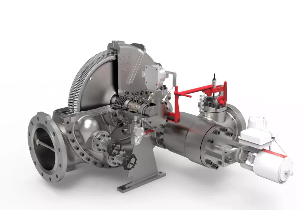
We design, manufacture and assembly Power Machines such as – diesel generators, electric motors, vibration motors, pumps, steam engines and steam turbines
EMS Power Machines is a global power engineering company, one of the five world leaders in the industry in terms of installed equipment. The companies included in the company have been operating in the energy market for more than 60 years.
EMS Power Machines manufactures steam turbines, gas turbines, hydroelectric turbines, generators, and other power equipment for thermal, nuclear, and hydroelectric power plants, as well as for various industries, transport, and marine energy.
EMS Power Machines is a major player in the global power industry, and its equipment is used in power plants all over the world. The company has a strong track record of innovation, and it is constantly developing new and improved technologies.
Here are some examples of Power Machines’ products and services:
- Steam turbines for thermal and nuclear power plants
- Gas turbines for combined cycle power plants and industrial applications
- Hydroelectric turbines for hydroelectric power plants
- Generators for all types of power plants
- Boilers for thermal power plants
- Condensers for thermal power plants
- Reheaters for thermal power plants
- Air preheaters for thermal power plants
- Feedwater pumps for thermal power plants
- Control systems for power plants
- Maintenance and repair services for power plants
EMS Power Machines is committed to providing its customers with high-quality products and services. The company has a strong reputation for reliability and innovation. Power Machines is a leading provider of power equipment and services, and it plays a vital role in the global power industry.
EMS Power Machines, which began in 1961 as a small factory of electric motors, has become a leading global supplier of electronic products for different segments. The search for excellence has resulted in the diversification of the business, adding to the electric motors products which provide from power generation to more efficient means of use.