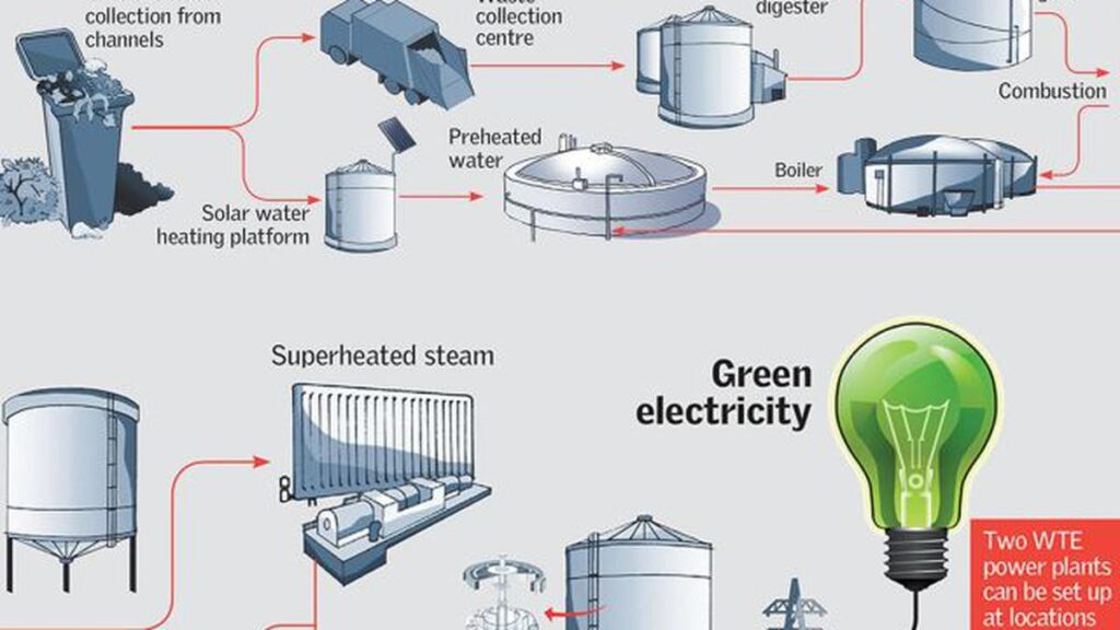
Waste-to-Energy Plants: Waste-to-Energy (WtE) plants are specialized facilities designed to generate electricity and/or heat by converting municipal solid waste (MSW), industrial waste, or other types of combustible waste materials into energy. These plants play a dual role in modern waste management: reducing the volume of waste sent to landfills while simultaneously producing usable energy, contributing to a circular economy and lowering reliance on fossil fuels.
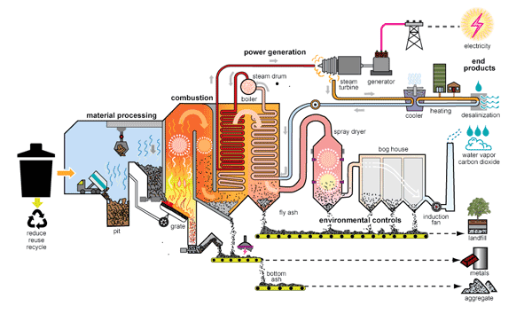
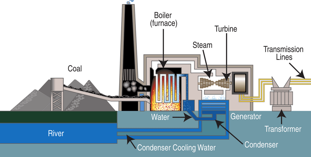
The core process in a typical WtE plant involves the controlled combustion of waste in a boiler or furnace. The heat produced from combustion converts water into high-pressure steam, which then drives a steam turbine connected to an electricity generator. In some cases, combined heat and power (CHP) systems are employed to provide both electricity and district heating to nearby industrial or residential areas, improving overall plant efficiency. Advanced WtE plants often use fluidized bed combustion, grate furnaces, or gasification technologies to optimize energy recovery and reduce emissions.
Waste preprocessing is an essential step to ensure efficient combustion. This may include sorting recyclables, removing metals, shredding, and drying waste to achieve a uniform calorific value. Some plants co-fire biomass or other renewable materials alongside conventional waste to enhance energy output and reduce carbon emissions.
Flue gas cleaning is another critical component, as combustion of waste can release pollutants such as particulate matter, acidic gases, heavy metals, and dioxins. Modern WtE facilities employ sophisticated air pollution control systems, including electrostatic precipitators, fabric filters, scrubbers, and selective catalytic reduction units to meet stringent environmental regulations.
Ash handling is also a key aspect of plant operation. Bottom ash, the non-combustible residue from the furnace, can often be processed and repurposed in construction materials, while fly ash, collected from flue gas treatment, must be stabilized and safely disposed of due to its higher concentration of heavy metals.
Control and monitoring systems ensure safe and efficient operation, providing real-time data on combustion parameters, emissions, and energy output. Automation and advanced control strategies enhance reliability and optimize fuel-to-energy conversion.
In addition to conventional thermal WtE plants, emerging technologies such as pyrolysis, plasma gasification, and anaerobic digestion are being explored. These methods can further improve energy recovery, reduce emissions, and enable the extraction of valuable byproducts like biochar, synthetic gas, or digestate for agricultural use.
Overall, Waste-to-Energy plants are a crucial component of sustainable waste management infrastructure, offering a practical solution to the growing challenges of urbanization and resource scarcity, while simultaneously generating renewable energy and minimizing environmental impact.
Main Types of Waste-to-Energy Plants
Waste-to-Energy (WtE) plants can be classified into several main types based on the technology used to convert waste into energy. Each type has specific advantages, efficiencies, and applications:
1. Mass Burn Incineration Plants:
This is the most common WtE technology. Municipal solid waste (MSW) is burned directly on a grate in a furnace. The heat generated produces steam to drive a turbine and generate electricity. Mass burn plants are straightforward in design, can handle large volumes of heterogeneous waste, and are equipped with advanced flue gas cleaning systems to minimize emissions.
2. Refuse-Derived Fuel (RDF) or Solid Recovered Fuel (SRF) Plants:
In this type, waste is first pretreated—sorted, shredded, and dried—to produce a more uniform fuel called RDF or SRF. This fuel has higher calorific value than raw MSW, allowing for more efficient combustion. RDF can be used in dedicated WtE boilers or co-fired in conventional power plants and cement kilns.
3. Fluidized Bed Combustion Plants:
Fluidized bed WtE plants burn waste on a bed of sand or other inert material that is kept in suspension by a flow of air. This technology allows for more uniform and complete combustion at lower temperatures, reducing the formation of nitrogen oxides (NOx) and dioxins. Fluidized beds are particularly suited for high-moisture or heterogeneous waste streams.
4. Gasification Plants:
Gasification converts waste into a synthetic gas (syngas) under high temperatures in a low-oxygen environment. The syngas, consisting mainly of carbon monoxide, hydrogen, and methane, can be burned to generate electricity or used as a feedstock for chemical production. Gasification produces less ash and can be cleaner than direct combustion if flue gas cleaning is adequate.
5. Pyrolysis Plants:
Pyrolysis is the thermal decomposition of waste in the absence of oxygen, producing syngas, oils, and char. The syngas can be used for electricity generation, while the pyrolysis oil can be refined as a fuel. This method is suitable for plastics and tires, but less common for mixed MSW.
6. Anaerobic Digestion (Biogas Plants):
Organic waste such as food scraps, agricultural residues, and sewage sludge is decomposed by microorganisms in oxygen-free tanks, producing biogas (mainly methane) and digestate. The biogas can be burned in engines or turbines to generate electricity and heat. Anaerobic digestion is especially suitable for wet, high-organic-content waste.
7. Plasma Arc Gasification:
This advanced technology uses extremely high temperatures generated by plasma torches to convert waste into syngas and vitrified slag. It can handle hazardous or medical waste and produces minimal emissions and residue. Plasma arc systems are highly efficient but have higher capital and operational costs.
Each WtE type is chosen based on the waste composition, local energy demands, environmental regulations, and economic considerations. Modern WtE plants often combine technologies, such as mass burn with flue gas energy recovery or RDF co-firing with conventional boilers, to optimize energy efficiency and reduce environmental impact.
Mass Burn Incineration Plants
Mass Burn Incineration Plants are the most widely used type of Waste-to-Energy (WtE) facility and are designed to directly combust municipal solid waste (MSW) without significant preprocessing. In these plants, waste is delivered to a reception and storage area, where it is temporarily held and homogenized to ensure continuous and stable feeding into the furnace. Large cranes or automated conveyors transport the waste onto a moving grate inside the combustion chamber. The grate system is designed to progressively move the waste through different temperature zones, ensuring complete combustion. Primary air is supplied from below the grate to facilitate combustion, while secondary air is injected above the waste to complete the burning of volatile gases.
The heat released during combustion is absorbed by water in boiler tubes surrounding the furnace, generating high-pressure steam. This steam is routed to a steam turbine connected to an electricity generator, producing electrical energy for local grids or industrial use. In many modern mass burn plants, combined heat and power (CHP) systems are integrated to supply district heating or industrial process steam, increasing overall plant efficiency.
Flue gas cleaning is a critical aspect of mass burn operations. Combustion of heterogeneous waste produces pollutants, including particulate matter, acid gases, heavy metals, and dioxins. To address this, mass burn plants use multi-stage flue gas treatment systems, which may include electrostatic precipitators or fabric filters to remove dust, wet or dry scrubbers to neutralize acidic components, and activated carbon injection to capture heavy metals and organic pollutants. Continuous monitoring ensures compliance with stringent environmental standards.
Ash handling is another important component. Bottom ash, which remains on the grate, is collected and can often be processed for use in construction materials, while fly ash from flue gas treatment is treated and stabilized due to its higher concentration of toxic elements. Automated systems transport both types of ash to storage or disposal areas.
Mass burn incineration plants are capable of handling large volumes of mixed waste with relatively low operational complexity compared to other WtE technologies. Their design emphasizes reliability, continuous operation, and efficient energy recovery, making them a cornerstone of modern urban waste management strategies.
Mass Burn Incineration Plants consist of several main parts, each critical to the efficient and safe conversion of municipal solid waste into energy. These components work together to handle waste, generate steam, control emissions, and manage residues:
1. Waste Reception and Storage Area:
This is the entry point for incoming municipal solid waste. Trucks deliver waste to a tipping floor or bunker, where it is temporarily stored. Cranes, grabbers, or conveyors move the waste to the feeding system. The storage area ensures a continuous supply of waste to the furnace and allows for preliminary sorting of oversized or non-combustible items.
2. Waste Feeding System:
The feeding system transports waste from the storage area into the furnace. It typically consists of conveyors, hoppers, and feeding chutes designed to meter waste at a controlled rate to maintain optimal combustion conditions. Automation in feeding ensures continuous operation without overloading the furnace.
3. Combustion Chamber / Furnace with Grate System:
The heart of the mass burn plant is the furnace. Waste is burned on a moving grate, which advances material through different temperature zones to achieve complete combustion. Primary air is supplied beneath the grate to support burning, and secondary air is injected above the waste to oxidize combustible gases. The design of the grate ensures uniform combustion, efficient energy release, and minimal unburned residues.
4. Boiler and Steam Generation System:
Surrounding the furnace, water-filled boiler tubes absorb heat from combustion and convert it into high-pressure steam. This steam is routed to a turbine-generator system to produce electricity. In combined heat and power (CHP) configurations, some of the steam can also be extracted for industrial use or district heating, enhancing overall efficiency.
5. Steam Turbine and Generator:
The high-pressure steam drives a turbine connected to an electricity generator. The turbine converts thermal energy into mechanical energy, which the generator then transforms into electrical energy. Condensers and cooling systems are used to convert exhaust steam back to water for reuse in the boiler.
6. Flue Gas Cleaning System:
Combustion of mixed waste produces pollutants, so flue gas cleaning is essential. Systems may include:
- Electrostatic precipitators or fabric filters for particulate removal
- Wet or dry scrubbers to neutralize acidic gases such as HCl and SO₂
- Activated carbon injection or catalytic systems to capture heavy metals and dioxins
Continuous monitoring ensures compliance with environmental regulations.
7. Ash Handling System:
Mass burn plants generate two types of ash: bottom ash (residue from the grate) and fly ash (captured from flue gas). Bottom ash is collected, cooled, and can be processed for reuse in construction materials. Fly ash, containing higher concentrations of heavy metals and toxins, is stabilized and disposed of safely. Conveyors, hoppers, and storage silos are used to handle both ash types efficiently.
8. Control and Monitoring Systems:
Advanced automation and control systems manage waste feeding, combustion conditions, steam generation, emission treatment, and ash handling. Real-time sensors and feedback loops ensure optimal performance, energy efficiency, and safety.
These main parts form an integrated system that allows mass burn incineration plants to convert heterogeneous municipal waste into usable energy while minimizing environmental impact.
Waste Reception and Storage Area
The Waste Reception and Storage Area is the first and a critical part of a Mass Burn Incineration Plant, serving as the entry point for municipal solid waste (MSW) and ensuring a continuous, controlled supply to the furnace. Incoming waste is typically delivered by trucks to the tipping floor or storage bunker. Here, waste is temporarily held, allowing plant operators to manage fluctuations in delivery rates and maintain steady combustion in the furnace.
The storage area is designed to accommodate large volumes of heterogeneous waste, including household refuse, commercial waste, and non-recyclable materials. It is often equipped with robust concrete bunkers resistant to wear, fire, and corrosive substances. Overhead cranes, hydraulic grabs, or automated conveyors are used to transfer waste from the tipping floor to the feeding system. These handling systems ensure that oversized items, such as furniture or large plastics, can be separated or broken down if necessary, preventing damage to downstream equipment.
Effective storage and reception management also allow for preliminary sorting to remove bulky inerts, metals, or hazardous materials that could interfere with combustion. In some modern facilities, mechanical pre-shredding or homogenization systems are integrated within the storage area to create a more uniform waste feed, improving boiler efficiency and reducing the risk of incomplete combustion.
Additionally, the design of the waste reception area emphasizes safety, ventilation, and odor control. Dust suppression, negative pressure ventilation, and fire detection systems are commonly installed to protect workers and prevent environmental hazards. Automation and monitoring systems track the quantity, composition, and flow of incoming waste, ensuring that the furnace receives a steady, controlled feed rate, which is essential for maintaining stable combustion, maximizing energy recovery, and minimizing emissions.
The Waste Reception and Storage Area, therefore, serves not only as a logistical hub for waste intake but also as a vital first step in optimizing the performance, safety, and environmental compliance of the entire mass burn incineration plant.
Waste Feeding System
The Waste Feeding System is a critical component of a Mass Burn Incineration Plant, responsible for transporting municipal solid waste (MSW) from the reception and storage area into the furnace at a controlled and consistent rate. Its primary function is to ensure that the combustion chamber receives a continuous feed of waste, allowing stable combustion, optimal energy recovery, and efficient operation of the plant.
Typically, the feeding system consists of heavy-duty conveyors, hoppers, chutes, and sometimes ram feeders or pushers. After waste is stored in the bunker or tipping floor, overhead cranes or hydraulic grabs transfer it onto the conveyor system. In some plants, mechanical shredders or homogenizers are integrated before feeding to break down bulky or irregular waste, ensuring a uniform size and composition that improves combustion efficiency.
The feeding system is designed for precision and reliability. Feed rates are carefully controlled through automated systems that monitor the furnace’s temperature, oxygen levels, and steam generation. By adjusting the speed of conveyors, the movement of ram feeders, or the operation of pushers, operators can maintain an optimal fuel-to-air ratio, preventing under- or over-firing, reducing the formation of unburned residues, and minimizing harmful emissions.
Safety and durability are also key considerations. The feeding system must handle abrasive and heterogeneous waste without frequent maintenance. Fire-resistant materials, robust construction, and emergency shutoff mechanisms are standard features. In addition, dust suppression systems and enclosures are often included to reduce airborne particulates, improve operator safety, and maintain environmental compliance.
In modern mass burn plants, the waste feeding system is integrated with the plant’s overall control and monitoring architecture. Sensors track the weight, volume, and moisture content of the incoming waste, allowing automatic adjustments to feed rates. This integration ensures that the furnace operates at steady temperatures, maximizes energy conversion, and supports consistent steam production for electricity or heat generation.
The Waste Feeding System, therefore, serves as the vital link between the storage area and the combustion chamber, ensuring that the plant operates efficiently, safely, and in compliance with environmental standards.
Combustion Chamber / Furnace with Grate System
The Combustion Chamber, or Furnace, with the Grate System is the central component of a Mass Burn Incineration Plant, where the actual conversion of municipal solid waste (MSW) into heat energy occurs. It is engineered to provide complete and efficient combustion of heterogeneous waste while ensuring safety, reliability, and compliance with environmental regulations.
In a mass burn plant, waste delivered from the feeding system is deposited onto a moving grate inside the furnace. The grate is typically segmented and mechanically driven, moving the waste progressively through different temperature zones. This design ensures that combustion occurs in stages: drying, ignition, volatile gas combustion, and final burnout of remaining solids. The moving grate allows uniform air distribution and effective mixing of the waste, optimizing heat release and minimizing unburned residues.
Air supply is a critical element in the combustion process. Primary air is injected from beneath the grate to support combustion of solid waste at the base, while secondary air is introduced above the grate to burn volatile gases released during pyrolysis. Some modern furnaces also include tertiary air injection to reduce emissions and improve the thermal efficiency of the process. By precisely controlling the air-to-fuel ratio, the furnace can maintain high combustion efficiency and reduce the formation of pollutants such as carbon monoxide, dioxins, and particulate matter.
The furnace is surrounded by boiler tubes or water walls that absorb the heat generated during combustion. These tubes convert water into high-pressure steam, which is then used in turbines for electricity generation or in combined heat and power (CHP) systems for district heating or industrial process steam. The design of the furnace ensures even heat distribution and maximum energy recovery while maintaining safe operating temperatures and pressures.
Durability and safety are central to the construction of the combustion chamber. High-temperature-resistant refractory lining protects the furnace walls from thermal stress and corrosion caused by acidic components in the waste. Continuous monitoring systems track temperature, oxygen levels, and combustion efficiency, allowing automated adjustments to air supply, grate speed, and feed rates. Fire detection systems and emergency shut-off mechanisms are also integrated to prevent accidents and ensure operational safety.
In addition, the furnace design facilitates the handling of combustion residues. Bottom ash, collected from the grate, can be cooled and processed for recycling, while fly ash, carried with flue gases, is directed toward the flue gas cleaning system for safe removal and disposal.
The Combustion Chamber with the Grate System is therefore the heart of a mass burn incineration plant, transforming heterogeneous waste into usable energy with controlled emissions, high thermal efficiency, and robust operational reliability.
Boiler and Steam Generation System
The Boiler and Steam Generation System in a Mass Burn Incineration Plant is a critical component that converts the thermal energy produced during combustion into high-pressure steam, which can then be used to generate electricity or supply heat in combined heat and power (CHP) applications. This system surrounds or is integrated with the furnace and is designed to efficiently capture heat while withstanding the harsh conditions of waste combustion.
Water-filled boiler tubes, often referred to as water walls, are positioned along the furnace walls and sometimes above the combustion chamber. As the municipal solid waste burns on the grate, the intense heat—typically ranging from 850°C to 1,100°C—is transferred to the water circulating in these tubes. This heat converts water into high-pressure, high-temperature steam. The design of the boiler maximizes heat absorption by using multiple passes for flue gases, including superheaters, economizers, and reheaters, ensuring that the energy from combustion is efficiently captured before gases exit to the flue gas cleaning system.
Superheaters raise the steam temperature above its saturation point, improving the efficiency of the steam turbine and electricity generation. Economizers preheat the feedwater entering the boiler using residual heat from flue gases, reducing fuel requirements and enhancing overall plant efficiency. Reheaters may be included in larger systems to improve the efficiency and stability of the turbine operation, particularly in CHP plants.
The boiler and steam system are equipped with multiple safety and monitoring mechanisms. Pressure and temperature sensors continuously track operating conditions, ensuring that steam is produced within design limits. Automatic control systems adjust water flow, feed rates, and combustion air supply to maintain stable steam production despite variations in waste composition or calorific value. Safety valves and emergency shutdown protocols protect against overpressure or overheating scenarios, ensuring reliable and safe operation.
In some mass burn plants, the boiler system is integrated with flue gas heat recovery devices, such as economizers or air preheaters, which capture residual heat from gases before they enter the flue gas cleaning system. This further increases overall energy efficiency and reduces fuel consumption.
The generated steam is directed to a steam turbine, where thermal energy is converted into mechanical energy and then into electricity via a generator. In combined heat and power systems, part of the steam can also be extracted at various stages of the turbine to supply district heating or industrial process steam, achieving higher total energy utilization.
Overall, the Boiler and Steam Generation System is the backbone of energy conversion in a mass burn incineration plant, transforming the heat from heterogeneous waste combustion into controlled, high-pressure steam for electricity production and heat supply while ensuring safety, efficiency, and operational stability.
Steam Turbine and Generator
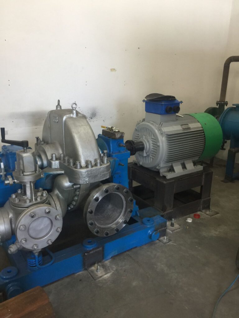
The Steam Turbine and Generator system is a core component of a Mass Burn Incineration Plant, responsible for converting thermal energy from steam into mechanical energy and subsequently into electrical energy for distribution or on-site use. High-pressure, high-temperature steam produced in the boiler is directed into the turbine, where it expands through a series of blades mounted on a rotating shaft. The expansion of steam across the turbine stages causes the shaft to spin, converting thermal energy into mechanical rotational energy.
Turbines are typically designed as multi-stage, condensing units to maximize energy extraction from the steam. In larger installations, back-pressure or extraction-condensing turbines may be used for combined heat and power (CHP) applications, allowing part of the steam to be diverted for industrial processes or district heating while the remaining steam continues through the turbine for electricity generation. The turbine design ensures minimal energy loss while maintaining stable operation under varying steam flows and pressures, which are common in waste combustion due to fluctuations in calorific value and feed rate.
The turbine shaft is mechanically coupled to an electrical generator, usually a synchronous generator, which converts the rotational energy into electricity. The generator produces alternating current (AC), which is then stepped up by transformers for transmission to the electrical grid or supplied directly to industrial consumers. Modern generator systems are equipped with protective relays, monitoring devices, and excitation control systems to maintain voltage stability, frequency regulation, and safe operation under varying load conditions.
Condensers and cooling systems are essential to turbine efficiency. Exhaust steam leaving the turbine is condensed back into water in a condenser, creating a pressure drop that allows the turbine to extract maximum energy from the steam. The condensed water is collected, treated, and pumped back into the boiler for reuse, completing a closed-loop cycle. Cooling may be achieved through air-cooled or water-cooled condensers depending on local environmental conditions and water availability.
The integration of the steam turbine and generator system with the boiler and combustion control systems is critical for maintaining plant efficiency and operational stability. Sensors continuously monitor steam pressure, temperature, flow rate, and turbine vibration, enabling automated adjustments and protective shutdowns if abnormal conditions arise.
In combined heat and power configurations, the turbine system is designed to balance electricity production with heat extraction, optimizing overall energy utilization. This flexibility allows the plant to respond to varying demand profiles for both electricity and process or district heating, improving economic performance and sustainability.
Overall, the Steam Turbine and Generator system transforms the thermal energy from waste combustion into reliable electrical power and usable heat, forming the heart of energy conversion in a Mass Burn Incineration Plant while ensuring safety, efficiency, and operational flexibility.
Flue Gas Cleaning System
The Flue Gas Cleaning System is a vital component of a Mass Burn Incineration Plant, designed to remove pollutants generated during the combustion of municipal solid waste (MSW) and ensure compliance with stringent environmental regulations. Because mass burn plants combust heterogeneous waste, the resulting flue gases contain a mixture of particulate matter, acid gases, heavy metals, dioxins, furans, and other potentially harmful compounds. The cleaning system integrates multiple treatment stages to reduce these emissions to safe levels before discharge through the stack.
The first stage typically involves particulate removal. Electrostatic precipitators (ESPs) or fabric filter baghouses capture fly ash and fine dust particles carried in the flue gas. ESPs use electrical fields to charge and collect particles on metal plates, while baghouses physically filter particles through specialized fabric bags. Efficient particulate removal is critical, as fly ash can contain concentrated heavy metals and unburned carbon.
Next, acid gas neutralization is performed to remove gases such as hydrogen chloride (HCl), sulfur dioxide (SO₂), and hydrogen fluoride (HF). This is often achieved using dry, semi-dry, or wet scrubbers. Dry scrubbers inject alkaline powders, such as hydrated lime or sodium bicarbonate, which react with acidic components to form stable salts. Wet scrubbers pass flue gas through a liquid solution that absorbs acid gases, which are later treated or neutralized.
Heavy metal and dioxin control is another essential function. Activated carbon is commonly injected into the flue gas stream to adsorb mercury, lead, cadmium, and organic pollutants like dioxins and furans. In some systems, catalytic reactors or selective catalytic reduction (SCR) units are also employed to further reduce nitrogen oxides (NOx) and destroy trace organic pollutants.
Continuous monitoring and control systems are integrated into the flue gas cleaning process to ensure compliance with emission limits. Sensors measure concentrations of particulate matter, NOx, SO₂, CO, HCl, heavy metals, and dioxins, providing real-time feedback to optimize reagent injection, airflow, and scrubber operation. Automated systems adjust the treatment process based on gas composition and flow, ensuring consistent performance despite variations in waste type and calorific value.
Finally, treated flue gases are exhausted through the plant stack, with emission parameters continuously recorded to satisfy regulatory reporting requirements. Collected residues, including fly ash and reaction byproducts, are handled separately in the ash handling system, often stabilized or encapsulated before disposal due to their potential toxicity.
The Flue Gas Cleaning System is therefore critical for minimizing the environmental impact of waste-to-energy plants. By effectively removing particulates, acid gases, heavy metals, and organic pollutants, it ensures safe air emissions while allowing mass burn incineration plants to operate efficiently and sustainably.
Ash Handling System
The Ash Handling System is an essential component of a Mass Burn Incineration Plant, responsible for the safe, efficient collection, transport, and management of the solid residues generated during waste combustion. Combustion of municipal solid waste (MSW) produces two primary types of ash: bottom ash, which remains on the grate, and fly ash, which is carried with flue gases and captured in the flue gas cleaning system. Proper handling of both types is crucial for environmental compliance, operational efficiency, and potential resource recovery.
Bottom ash is the coarse, non-combustible residue left on the furnace grate after combustion. It typically contains metals, ceramics, glass, and other inert materials. Bottom ash is collected in a quenching pit or hopper, where it is cooled using water to prevent residual combustion and reduce dust formation. Once cooled, bottom ash is conveyed to storage silos or processing areas. In many modern WtE plants, bottom ash undergoes further treatment to recover ferrous and non-ferrous metals, which are separated using magnets and eddy current separators. The remaining material can be processed and recycled for construction applications, such as road base or concrete aggregate, contributing to circular economy objectives.
Fly ash is the fine particulate matter captured from flue gases during flue gas cleaning. Fly ash contains higher concentrations of heavy metals, salts, and potentially toxic compounds, making it hazardous and requiring careful handling. It is typically collected using fabric filters, electrostatic precipitators, or scrubbers and then stabilized by mixing with binding agents such as cement or lime to reduce leachability. After stabilization, fly ash is transported via sealed conveyors or pneumatic systems to secure storage or disposal facilities that meet regulatory requirements.
The ash handling system is designed for automation, safety, and dust control. Conveyors, screw feeders, hoppers, and silos are enclosed to minimize dust emissions and prevent worker exposure. Water sprays, airlocks, and negative pressure ventilation are often employed to suppress dust and avoid fugitive emissions. Sensors and control systems monitor ash levels, flow rates, and equipment performance, enabling continuous, reliable operation and integration with the overall plant control system.
By efficiently managing both bottom and fly ash, the Ash Handling System ensures that solid residues are safely contained, processed for potential material recovery, or disposed of in compliance with environmental regulations. It is a critical part of maintaining operational continuity, reducing environmental impact, and supporting the sustainability goals of modern mass burn incineration plants.
Control and Monitoring Systems
The Control and Monitoring Systems in a Mass Burn Incineration Plant are the central intelligence of the facility, responsible for ensuring safe, efficient, and environmentally compliant operation of all plant processes. These systems integrate advanced automation, real-time data acquisition, and process control to manage the complex interactions between waste feeding, combustion, steam generation, flue gas cleaning, ash handling, and energy conversion.
At the core of the system is a Supervisory Control and Data Acquisition (SCADA) platform or a Distributed Control System (DCS). This platform continuously collects data from hundreds of sensors placed throughout the plant, monitoring parameters such as furnace temperature, steam pressure and flow, oxygen levels, combustion air rates, feed rate of waste, flue gas composition, and ash handling operations. The SCADA/DCS provides operators with a real-time overview of the plant, enabling quick responses to any deviations from normal operating conditions.
Automation and process control are critical for maintaining combustion efficiency and emission compliance. The system automatically adjusts waste feed rates, grate speed, primary and secondary air flows, and boiler water circulation based on live measurements of temperature, oxygen, and steam production. This ensures stable combustion, optimal energy recovery, and minimal formation of pollutants such as carbon monoxide, nitrogen oxides, and dioxins. In CHP plants, the control system also balances electricity generation with heat extraction to meet variable energy demand.
Safety and alarm management are fully integrated into the control system. Fire detection, pressure and temperature limits, gas leak detection, and emergency shutdown mechanisms are monitored continuously. In case of abnormal conditions, the system can trigger automatic safety protocols, shut off feed systems, adjust airflow, or initiate emergency venting to prevent accidents and protect equipment and personnel.
Flue gas emissions monitoring is a key function of the control system. Continuous Emission Monitoring Systems (CEMS) measure concentrations of particulate matter, NOx, SO₂, HCl, CO, dioxins, and heavy metals in the exhaust gases. The system uses this data to automatically optimize reagent injection, scrubber operation, and other flue gas cleaning processes, ensuring compliance with environmental regulations and reporting requirements.
Advanced control systems may also incorporate predictive maintenance and diagnostics, using historical data and AI-based analytics to predict equipment wear, detect anomalies, and schedule maintenance proactively, reducing downtime and operational costs.
Overall, the Control and Monitoring Systems serve as the operational backbone of a mass burn incineration plant. By integrating real-time monitoring, automation, safety management, and emission control, these systems maximize energy efficiency, ensure environmental compliance, and maintain continuous, reliable operation of the plant.
Refuse-Derived Fuel (RDF) or Solid Recovered Fuel (SRF) Plants

Refuse-Derived Fuel (RDF) or Solid Recovered Fuel (SRF) plants are specialized Waste-to-Energy (WtE) facilities designed to convert municipal solid waste (MSW) or industrial waste into a high-calorific, uniform fuel that can be burned efficiently in dedicated boilers, co-fired in conventional power plants, or used in cement kilns. Unlike mass burn incineration plants, which combust waste directly on a grate, RDF/SRF plants focus on preprocessing and refining waste to produce a controlled, engineered fuel, improving energy recovery and reducing environmental impact.
The process begins in the waste reception and preprocessing area, where incoming MSW is sorted to remove bulky inerts, metals, glass, and non-combustible or hazardous materials. Mechanical shredders reduce the size of the waste, while screens and air classifiers separate lightweight, combustible fractions from heavier materials. Magnetic and eddy current separators remove ferrous and non-ferrous metals, and further drying or homogenization may be applied to achieve a consistent moisture content and particle size. This preprocessing results in a uniform fuel that is easier to handle, store, and burn efficiently.
Once prepared, the RDF or SRF is baled, pelletized, or stored in silos, depending on the plant design and downstream energy use. The high calorific value, reduced moisture content, and uniform composition of RDF/SRF allow it to be fed into specialized combustion systems, such as fluidized bed boilers, grate-fired RDF boilers, or cement kiln burners, with precise control over energy output and emissions. Co-firing RDF/SRF with coal or biomass in existing power plants is also common, providing a sustainable alternative fuel while reducing fossil fuel consumption.
The combustion system in RDF/SRF plants is designed to maximize energy extraction while minimizing pollutant formation. Secondary air injection, staged combustion, and temperature control ensure complete burning of volatiles, while flue gas cleaning systems remove particulate matter, acid gases, heavy metals, and organic pollutants. Continuous monitoring maintains compliance with environmental standards and optimizes combustion efficiency.
Ash handling systems manage the residues from RDF/SRF combustion. Bottom ash can often be recycled for construction materials, while fly ash collected in flue gas cleaning systems is stabilized and safely disposed of due to its higher concentration of heavy metals and toxins.
Advanced control and monitoring systems integrate the preprocessing, combustion, and emissions control processes, ensuring stable operation despite variations in fuel composition, moisture content, or calorific value. Automated systems adjust feed rates, combustion air, boiler conditions, and emission treatment parameters to maintain consistent energy output and regulatory compliance.
RDF/SRF plants offer several advantages over conventional mass burn incineration. By producing a uniform fuel, they improve combustion efficiency, reduce the formation of pollutants, and allow flexible energy recovery through multiple applications. Additionally, preprocessing enables better separation of recyclables and metals, supporting circular economy objectives. These facilities are increasingly used in urban and industrial settings where controlled, high-calorific waste fuel can supplement conventional energy sources while minimizing landfill disposal.
Refuse-Derived Fuel (RDF) or Solid Recovered Fuel (SRF) plants consist of several main parts, each designed to transform heterogeneous waste into a uniform, high-calorific fuel and to efficiently convert it into energy while minimizing environmental impact. These components work together to ensure proper preprocessing, fuel handling, combustion, and emissions control:
1. Waste Reception and Storage Area:
Incoming municipal solid waste (MSW) or industrial waste is delivered to a reception area, typically a tipping floor or bunker. Waste is temporarily stored here to ensure a continuous and controlled supply to preprocessing systems. Overhead cranes, grabbers, or conveyors transport the waste, and preliminary sorting may remove oversized, hazardous, or non-combustible materials. This area also serves as a buffer to manage fluctuations in waste delivery.
2. Preprocessing and Sorting Systems:
The core of an RDF/SRF plant is the preprocessing stage, where waste is converted into a uniform fuel. Mechanical shredders reduce particle size, while trommel screens, air classifiers, and vibrating screens separate lightweight combustible fractions from heavier inerts. Magnetic and eddy current separators extract ferrous and non-ferrous metals, which can be recycled. Additional drying or homogenization may be applied to achieve consistent moisture content and calorific value. This stage ensures that the produced fuel burns efficiently with predictable energy output.
3. Fuel Production and Storage:
Processed waste is formed into RDF or SRF in various forms such as loose fuel, bales, or pellets. Storage silos, hoppers, or fuel bunkers provide temporary storage and maintain continuous supply to combustion systems. Automated handling ensures controlled feed rates to downstream boilers or co-firing applications.
4. Combustion System:
RDF/SRF is burned in specialized boilers, fluidized bed systems, or co-fired in existing power or cement plants. The combustion system is designed to optimize energy recovery while minimizing emissions. Staged air injection, temperature control, and residence time management ensure complete combustion of volatiles and solid fractions. Steam generation or direct heat output depends on the energy recovery strategy of the facility.
5. Flue Gas Cleaning System:
Combustion of RDF/SRF produces flue gases containing particulate matter, acid gases, heavy metals, and organic pollutants. Multi-stage cleaning systems are employed, including fabric filters or electrostatic precipitators for dust removal, wet or dry scrubbers for acid gases, and activated carbon or catalytic systems for heavy metals and dioxins. Continuous emission monitoring ensures compliance with environmental regulations.
6. Ash Handling System:
Combustion residues are managed via ash handling systems. Bottom ash is collected, cooled, and may undergo processing to recover metals or for use in construction materials. Fly ash captured from flue gas cleaning contains higher concentrations of hazardous elements and is stabilized before secure disposal. Automated conveyors, hoppers, and silos facilitate efficient and safe handling of all residues.
7. Control and Monitoring Systems:
Advanced control systems integrate all plant processes, from preprocessing to combustion and emission treatment. Sensors monitor temperature, moisture, feed rate, air flow, steam production, and flue gas composition. Automated feedback loops adjust system parameters in real time to optimize energy efficiency, maintain safe operation, and ensure regulatory compliance. Predictive maintenance features may also be incorporated to reduce downtime and improve reliability.
These main parts form an integrated system that allows RDF/SRF plants to convert heterogeneous waste into a uniform fuel and subsequently into energy, while maintaining operational efficiency, environmental compliance, and safety.
Waste Reception and Storage Area
The Waste Reception and Storage Area in a Refuse-Derived Fuel (RDF) or Solid Recovered Fuel (SRF) plant is the first and a crucial part of the facility, serving as the entry point for incoming municipal solid waste (MSW) or industrial waste and ensuring a steady, controlled supply to the preprocessing systems. Waste delivered by trucks is typically unloaded onto a tipping floor or into a storage bunker. This area functions as a buffer, allowing the plant to manage fluctuations in delivery rates and maintain a continuous feed to downstream equipment.
The design of the reception and storage area emphasizes capacity, durability, and safety. Concrete bunkers with high wear and fire resistance are commonly used to withstand the abrasive and potentially reactive nature of waste. Overhead cranes, hydraulic grabs, or automated conveyors transport the waste from the tipping floor into the preprocessing system. This allows for separation of oversized items, hazardous materials, or non-combustible fractions that could damage shredders or disrupt fuel production.
Effective preliminary sorting and homogenization can also occur in the storage area. Large objects such as furniture, metal scrap, or construction debris may be manually or mechanically removed, while initial shredding or blending can help create a more uniform feedstock. This improves the quality and consistency of the RDF/SRF, resulting in higher calorific value and more efficient combustion in the boiler or co-fired system.
Safety, ventilation, and environmental control are essential in the waste reception area. Dust suppression systems, negative-pressure ventilation, and odor control mechanisms protect workers and minimize environmental impact. Fire detection and emergency suppression systems are also integrated due to the combustible nature of stored waste.
Automation and monitoring enhance operational efficiency. Sensors track the quantity, composition, and flow of incoming waste, allowing operators to optimize feed rates to the preprocessing system and ensure consistent fuel quality.
In summary, the Waste Reception and Storage Area is a critical hub in RDF/SRF plants, providing secure, controlled, and continuous handling of incoming waste while supporting preliminary sorting, homogenization, and environmental and operational safety.
Preprocessing and Sorting Systems
The Preprocessing and Sorting Systems are the core of a Refuse-Derived Fuel (RDF) or Solid Recovered Fuel (SRF) plant, responsible for transforming heterogeneous municipal solid waste (MSW) or industrial waste into a uniform, high-calorific fuel suitable for efficient combustion. These systems ensure that the final RDF/SRF product has consistent particle size, moisture content, and energy value, which improves boiler performance, reduces emissions, and enables reliable energy production.
After waste is transferred from the reception and storage area, it enters mechanical preprocessing units. Shredders or hammer mills reduce large items and bulky materials into smaller, manageable particles. This size reduction facilitates easier separation of combustible and non-combustible fractions and ensures uniform feeding into the fuel production system.
Sorting systems then separate materials based on weight, size, or magnetic properties. Trommel screens, vibrating screens, and air classifiers are used to remove inerts such as stones, glass, and sand. Magnetic separators extract ferrous metals, while eddy current separators recover non-ferrous metals like aluminum and copper. These recovered metals can be recycled, enhancing the plant’s sustainability and circular economy performance.
Moisture control is a critical aspect of preprocessing. High moisture content reduces the calorific value of the RDF/SRF and can affect combustion efficiency. Drying systems, including mechanical or thermal dryers, are often integrated to achieve a target moisture range, producing a more consistent and energy-dense fuel. In some facilities, homogenization systems blend different waste fractions to further standardize fuel quality.
Advanced preprocessing lines may also include dust suppression and odor control measures to maintain environmental compliance and protect workers. Enclosed conveyors, water sprays, and negative-pressure ventilation prevent fugitive dust and minimize unpleasant odors.
Finally, sensors and monitoring equipment track particle size distribution, moisture content, and calorific value in real time. Automated feedback systems adjust shredding, drying, and sorting parameters to maintain consistent fuel quality, ensuring that the RDF/SRF meets the specifications required for downstream combustion systems.
In summary, the Preprocessing and Sorting Systems convert heterogeneous waste into a predictable, high-calorific fuel. By combining shredding, separation, drying, and homogenization with advanced monitoring, these systems ensure that RDF/SRF plants operate efficiently, safely, and in compliance with environmental standards.
Fuel Production and Storage
The Fuel Production and Storage stage in a Refuse-Derived Fuel (RDF) or Solid Recovered Fuel (SRF) plant is where preprocessed waste is transformed into a uniform, energy-dense fuel ready for combustion. This stage ensures that the final RDF/SRF product meets the required specifications for particle size, moisture content, density, and calorific value, enabling efficient energy recovery and consistent plant operation.
After preprocessing and sorting, the combustible fraction of waste is directed to fuel formation systems. Depending on plant design and downstream requirements, RDF/SRF may be processed into loose fuel, baled fuel, or pellets. Mechanical compactors and balers compress shredded material into dense bales, which facilitate storage, handling, and transport. Pelletizing systems produce small, uniform cylindrical fuel pellets, improving combustion efficiency and reducing dust and handling issues.
Storage facilities are designed to maintain a continuous supply of fuel to the combustion system while preserving fuel quality. Silos, hoppers, and fuel bunkers store loose, baled, or pelletized RDF/SRF under controlled conditions. Storage areas are often enclosed and equipped with ventilation, dust suppression, and fire detection systems to prevent ignition, reduce fugitive emissions, and maintain safety. Automated conveyors, feeders, or augers move fuel from storage to the boiler or co-firing system at a controlled rate, ensuring steady combustion and stable energy output.
Moisture control and quality monitoring are critical during storage. Excess moisture can reduce calorific value and affect boiler performance, so some plants use aeration, controlled ventilation, or additional drying to maintain fuel within the desired specifications. Sensors and monitoring systems track fuel temperature, moisture content, and flow rates, feeding data into the plant’s control system to adjust feeding rates and maintain consistent combustion conditions.
In addition to operational efficiency, the Fuel Production and Storage stage supports logistics and flexibility. Baled or pelletized RDF/SRF can be transported to external energy facilities, such as cement kilns or power plants, enabling decentralized energy recovery. Storage capacity ensures that the plant can handle fluctuations in waste supply or fuel demand without interrupting operations.
Overall, the Fuel Production and Storage stage is essential for converting preprocessed waste into a high-quality, uniform fuel and maintaining a reliable supply to combustion systems. It combines mechanical processing, quality control, and safe storage practices to optimize energy recovery, reduce emissions, and support sustainable waste-to-energy operations.
Combustion System
The Combustion System in a Refuse-Derived Fuel (RDF) or Solid Recovered Fuel (SRF) plant is the central unit where the processed fuel is converted into usable thermal energy. Unlike mass burn incineration plants, which burn heterogeneous waste directly, RDF/SRF combustion relies on a uniform, engineered fuel, allowing for more efficient, controlled, and cleaner burning. The combustion system is designed to maximize energy recovery while minimizing emissions and operational issues.
RDF/SRF fuel is fed into the boiler or furnace using automated conveyors, hoppers, or feeding systems that ensure a continuous and controlled supply. Depending on the plant configuration, the fuel may be burned in grate-fired boilers, fluidized bed systems, or rotary kilns. Grate-fired systems move the fuel over a mechanically driven grate, providing staged combustion zones for drying, ignition, volatile gas combustion, and final burnout. Fluidized bed boilers suspend the fuel on a bed of inert particles, allowing uniform heat distribution, efficient combustion of high-moisture fuels, and reduced formation of nitrogen oxides (NOx).
Air supply management is crucial for efficient combustion. Primary air supports the burning of solid fuel at the base of the furnace, while secondary and sometimes tertiary air is injected above the fuel to oxidize volatile gases released during pyrolysis. Proper staging of air prevents incomplete combustion, reduces carbon monoxide emissions, and ensures complete burnout of RDF/SRF. Combustion temperatures are carefully controlled, typically between 850°C and 1,100°C, to optimize energy extraction and minimize pollutant formation.
The heat generated during combustion is absorbed by boiler tubes or water walls, producing high-pressure steam for electricity generation or combined heat and power (CHP) applications. Advanced boiler designs may include superheaters, economizers, and reheaters to maximize energy capture and improve overall efficiency.
Emissions control integration begins in the combustion system itself. Stable and complete combustion reduces the formation of dioxins, furans, and particulate matter, lowering the load on downstream flue gas cleaning systems. Real-time sensors monitor temperature, oxygen levels, and combustion efficiency, feeding data to the control system to automatically adjust fuel feed rates, grate speed, and air supply.
The combustion system is also designed with residue management in mind. Bottom ash from the grate or bed is collected and cooled, while fly ash carried with flue gases is directed to the flue gas cleaning system for capture and safe disposal. Fire-resistant linings and refractory materials protect the furnace structure from high temperatures and corrosive components in RDF/SRF.
Overall, the Combustion System in an RDF/SRF plant is engineered to provide efficient, reliable, and environmentally responsible energy recovery. By combining controlled feeding, staged combustion, temperature management, and integration with steam generation and emissions control, it ensures maximum energy output and regulatory compliance.
Flue Gas Cleaning System
The Flue Gas Cleaning System in a Refuse-Derived Fuel (RDF) or Solid Recovered Fuel (SRF) plant is a critical component for controlling emissions and ensuring compliance with strict environmental standards. Even though RDF/SRF is a more uniform and energy-dense fuel than raw municipal solid waste, its combustion still produces pollutants such as particulate matter, acid gases, heavy metals, and organic compounds. The flue gas cleaning system removes these contaminants before the exhaust is released into the atmosphere.
The first stage typically involves particulate removal. Fly ash and other solid particles are captured using fabric filter baghouses or electrostatic precipitators (ESPs). Baghouse filters physically trap fine dust particles, while ESPs use electrical fields to collect particles on metal plates. Efficient particulate removal is essential because fly ash can contain concentrated heavy metals and unburned carbon.
Next, acid gas neutralization is performed to eliminate components such as hydrogen chloride (HCl), sulfur dioxide (SO₂), and hydrogen fluoride (HF). This is often accomplished using dry, semi-dry, or wet scrubbing systems. In dry scrubbers, alkaline reagents such as hydrated lime or sodium bicarbonate are injected into the flue gas, chemically neutralizing acids. Wet scrubbers use a liquid solution that absorbs acidic gases, which is later treated or neutralized.
Heavy metal and organic pollutant control is another key function. Activated carbon injection is commonly employed to adsorb mercury, lead, cadmium, and organic compounds such as dioxins and furans. In some RDF/SRF plants, selective catalytic reduction (SCR) or other catalytic processes are used to reduce nitrogen oxides (NOx) and destroy trace organic pollutants.
Continuous monitoring systems are integrated throughout the flue gas cleaning process. Sensors measure concentrations of particulate matter, NOx, SO₂, CO, HCl, heavy metals, and dioxins in real time. Automated feedback loops adjust reagent injection, airflow, and scrubber operation to optimize emission control and ensure compliance with regulatory limits.
After treatment, cleaned flue gases are discharged through the stack, while collected residues, including fly ash and scrubber byproducts, are handled in the ash handling system. Fly ash is stabilized and securely stored or disposed of due to its higher concentration of hazardous elements.
The Flue Gas Cleaning System in RDF/SRF plants is therefore crucial for minimizing environmental impact, reducing toxic emissions, and ensuring safe, compliant operation. By combining particulate filtration, acid gas neutralization, heavy metal capture, and continuous monitoring, it allows RDF/SRF plants to operate efficiently and sustainably.
Ash Handling System
The Ash Handling System in a Refuse-Derived Fuel (RDF) or Solid Recovered Fuel (SRF) plant is responsible for the safe collection, transport, and management of solid residues generated during combustion. Although RDF/SRF is a more uniform fuel than raw municipal solid waste, its combustion still produces two main types of ash: bottom ash, which remains in the furnace or boiler, and fly ash, which is carried with flue gases and captured in the flue gas cleaning system. Proper handling of both ash types is essential for environmental compliance, operational efficiency, and potential resource recovery.
Bottom ash consists of non-combustible materials, including metals, glass, ceramics, and inert components. It is collected in hoppers or pits beneath the combustion system and is often cooled with water to prevent residual combustion and reduce dust formation. After cooling, bottom ash can be transported via conveyors or screw feeders to storage areas or processing units. Metals can be recovered using magnetic or eddy current separators, while the remaining inert material may be recycled in construction applications such as road base or aggregate.
Fly ash, captured in the flue gas cleaning system, contains higher concentrations of hazardous elements, including heavy metals and salts. It is typically stabilized by mixing with binding agents such as cement or lime to reduce leachability before secure storage or disposal. Fly ash handling systems are fully enclosed, using pneumatic or mechanical transport systems to minimize dust emissions and prevent environmental contamination.
Safety and operational reliability are critical in ash handling. The system is designed with dust suppression, fire detection, and containment measures to protect workers and the environment. Enclosed conveyors, airlocks, and negative-pressure ventilation are commonly used to prevent fugitive emissions. Sensors monitor ash levels, flow rates, and equipment status, allowing automated control of ash transport, storage, and disposal operations.
By efficiently managing both bottom and fly ash, the Ash Handling System ensures that solid residues are safely contained, processed for potential material recovery, or disposed of in accordance with environmental regulations. It supports continuous plant operation, minimizes the environmental footprint of RDF/SRF combustion, and contributes to sustainable waste-to-energy management.
Control and Monitoring Systems
The Control and Monitoring Systems in a Refuse-Derived Fuel (RDF) or Solid Recovered Fuel (SRF) plant form the operational backbone of the facility, ensuring safe, efficient, and environmentally compliant operation across all processes. Given the variability in waste composition, moisture content, and calorific value—even in processed RDF/SRF—the control systems are critical for maintaining stable combustion, optimal energy recovery, and regulatory compliance.
At the core of the system is a Supervisory Control and Data Acquisition (SCADA) platform or a Distributed Control System (DCS). These systems continuously collect data from sensors installed throughout the plant, monitoring parameters such as fuel feed rates, boiler temperature and pressure, air supply, steam generation, flue gas composition, ash levels, and equipment status. The platform provides operators with real-time visualization of plant operation and enables automated responses to maintain optimal performance.
Automation and process control are central to maintaining efficient combustion and energy production. The system adjusts fuel feeding rates, grate or feeder speeds, primary and secondary air flows, and boiler water circulation in real time based on feedback from sensors monitoring oxygen levels, combustion temperature, and steam output. This ensures complete burnout of fuel, reduces the formation of pollutants such as carbon monoxide and nitrogen oxides (NOx), and maintains consistent steam or heat production for electricity or CHP applications.
Emissions monitoring is fully integrated into the control system. Continuous Emission Monitoring Systems (CEMS) measure particulate matter, NOx, SO₂, HCl, CO, dioxins, and heavy metals in the exhaust gases. The system uses this data to automatically optimize reagent injection, scrubber operation, and other flue gas treatment parameters, maintaining compliance with stringent environmental regulations.
Safety and alarm management are also integrated. Fire detection, emergency shutdown mechanisms, overpressure protection, and equipment failure alerts are continuously monitored. In the event of abnormal conditions, the system can initiate automated safety responses, such as stopping fuel feeding, adjusting airflow, or activating fire suppression, ensuring the safety of personnel, equipment, and the facility.
Advanced control systems may incorporate predictive maintenance and diagnostic features, using historical data and real-time monitoring to anticipate equipment wear, detect anomalies, and schedule maintenance proactively. This minimizes downtime, reduces operational costs, and ensures continuous plant availability.
Overall, the Control and Monitoring Systems in an RDF/SRF plant integrate real-time data acquisition, automation, emissions management, and safety protocols to maintain stable, efficient, and environmentally responsible operations. They are essential for maximizing energy recovery, ensuring regulatory compliance, and providing reliable, continuous operation of the facility.
Fluidized Bed Combustion Plants
Fluidized Bed Combustion (FBC) plants are a type of Waste-to-Energy (WtE) or biomass-fired power plant that utilize fluidized bed technology to efficiently combust a wide range of solid fuels, including municipal solid waste (MSW), biomass, refuse-derived fuel (RDF), and other heterogeneous fuels. Unlike conventional grate-fired or mass burn systems, fluidized bed combustion suspends fuel particles in a bed of hot, inert material—usually sand or ash—using a controlled flow of air, creating a fluid-like state. This enables uniform temperature distribution, high combustion efficiency, and reduced pollutant formation.
The main advantages of FBC technology include the ability to burn low-calorific fuels with high moisture content, precise temperature control to reduce nitrogen oxides (NOx) formation, and the capability to co-fire multiple types of fuels simultaneously. Fluidized beds operate at relatively lower combustion temperatures (typically 800–900°C), which reduces thermal stress on boiler components and minimizes the formation of dioxins and furans. The technology also allows in-situ capture of sulfur by injecting lime or limestone directly into the bed, reducing sulfur dioxide (SO₂) emissions without requiring extensive flue gas scrubbing.
Main parts of a Fluidized Bed Combustion Plant:
- Fuel Handling and Storage: Incoming fuels, including biomass, MSW, or RDF, are received and stored in dedicated bunkers or silos. Storage systems ensure a continuous, controlled supply to the fuel feeding system. Preprocessing may include shredding, drying, or homogenization to achieve a uniform particle size and moisture content.
- Fuel Feeding System: Fuel is transported from storage to the combustion chamber using automated conveyors, feeders, or pneumatic systems. Feed rates are controlled to maintain stable bed conditions and combustion efficiency.
- Fluidized Bed Combustion Chamber: The heart of the plant is the fluidized bed furnace. Air is blown from the bottom through a distributor plate, suspending fuel and inert bed material in a turbulent, fluid-like state. This ensures excellent mixing, uniform heat distribution, and complete combustion. Bed temperature is carefully controlled to optimize energy output and minimize pollutant formation. Limestone or other sorbents can be added directly to the bed to capture sulfur during combustion.
- Heat Recovery and Boiler System: The heat released in the combustion chamber is transferred to water-cooled tubes or boiler walls, generating high-pressure steam for electricity generation or combined heat and power (CHP) applications. Superheaters and economizers improve energy conversion efficiency.
- Flue Gas Cleaning System: FBC plants produce flue gases containing particulate matter, acid gases, and trace heavy metals. Multi-stage cleaning systems—including cyclones, fabric filters, scrubbers, and activated carbon injection—are employed to remove pollutants and ensure emissions meet regulatory standards.
- Ash Handling System: The combustion produces two main types of ash: bed ash, which consists of unreacted material and inert bed media, and fly ash, collected from flue gas cleaning. Bed ash may be recycled back into the furnace to maintain bed material or disposed of, while fly ash is stabilized and securely managed due to its potentially hazardous content.
- Control and Monitoring Systems: Advanced distributed control systems (DCS) or SCADA platforms monitor temperature, oxygen, fuel feed, bed fluidization, steam generation, and emissions. Automated adjustments maintain stable combustion, optimal energy production, and safe operation.
Fluidized Bed Combustion plants are especially suited for low-quality fuels with variable moisture content and calorific value, including biomass residues, RDF, and challenging waste streams. Their high efficiency, fuel flexibility, and lower pollutant emissions make them an increasingly preferred choice for sustainable energy recovery from waste and biomass sources.
Fuel Handling and Storage
The Fuel Handling and Storage system in a Fluidized Bed Combustion (FBC) plant is the first stage in the fuel-to-energy conversion process, responsible for receiving, storing, and preparing a continuous supply of fuel for combustion. Because FBC plants are designed to burn a wide variety of fuels—including municipal solid waste (MSW), biomass, refuse-derived fuel (RDF), and other heterogeneous or low-calorific fuels—this system must accommodate differences in size, moisture content, and energy density while ensuring operational efficiency and safety.
Incoming fuel is typically delivered via trucks, railcars, or conveyors and unloaded into reception areas, bunkers, or silos. These storage facilities are designed to act as a buffer, enabling the plant to manage fluctuations in fuel delivery and maintain a continuous feed to the combustion system. Bunkers and silos are constructed from wear-resistant, fire-resistant materials to withstand abrasive and combustible fuels. They often include features for ventilation, odor control, and dust suppression to protect operators and minimize environmental impact.
Preprocessing within the storage area may include mechanical shredding, screening, or blending to achieve uniform particle size, remove oversized or non-combustible materials, and homogenize moisture content. This ensures stable fluidized bed operation and consistent thermal performance in the combustion chamber. Magnetic and eddy current separators may also be installed to extract metals, supporting recycling and minimizing damage to downstream equipment.
The system incorporates automated feeding equipment such as conveyors, screw feeders, or pneumatic transport systems to deliver fuel at controlled rates to the fluidized bed furnace. Feed rate control is critical to maintaining the proper fuel-to-air ratio, bed fluidization, and combustion stability. Sensors continuously monitor fuel levels, flow rates, and temperature, feeding data to the plant’s control system for real-time adjustments.
Safety is a central consideration. Fuel storage areas are equipped with fire detection and suppression systems, temperature monitoring, and ventilation to prevent spontaneous combustion or fire hazards. Enclosures and negative-pressure systems minimize dust emissions, while safety interlocks prevent uncontrolled fuel discharge.
Overall, the Fuel Handling and Storage system ensures that a diverse range of fuels is securely received, properly conditioned, and continuously supplied to the fluidized bed combustion chamber. By combining robust construction, preprocessing, automated feeding, and integrated monitoring, it supports efficient, safe, and environmentally compliant operation of the FBC plant.
Fuel Feeding System
The Fuel Feeding System in a Fluidized Bed Combustion (FBC) plant is a critical link between fuel storage and the combustion chamber, ensuring a consistent, controlled, and precisely measured supply of fuel to the fluidized bed. Proper feeding is essential for maintaining stable bed fluidization, uniform combustion, optimal energy recovery, and reduced pollutant formation.
Fuel from storage silos, bunkers, or hoppers is transported to the combustion chamber using mechanical conveyors, screw feeders, belt feeders, or pneumatic systems, depending on the fuel type, particle size, and plant configuration. These systems are designed to handle a wide variety of fuels—including shredded MSW, biomass residues, refuse-derived fuel (RDF), or low-calorific industrial wastes—while preventing blockages, bridging, or surges that could destabilize the bed.
Feed rate control is a key aspect of the system. Sensors continuously monitor the fuel level in storage, the mass flow, and the temperature of the material. The plant’s control system adjusts feeding rates in real time to match combustion demand, maintain bed temperature, and optimize air-to-fuel ratios. This is especially important in FBC plants, where variations in fuel calorific value or moisture content can affect fluidization and combustion stability.
Advanced feeding systems also include fuel metering and distribution mechanisms to ensure even fuel delivery across the bed. In larger or multi-fuel installations, the system may include multiple feeders to inject different fuel types at precise locations in the bed, enabling co-firing and improving combustion efficiency.
Safety and environmental controls are integral. Enclosed conveyors and pneumatic systems reduce dust emissions, while fire detection sensors and emergency shut-off mechanisms prevent ignition outside the furnace. Anti-bridging devices, vibration feeders, and flow regulators help prevent fuel clogging and ensure continuous operation.
In summary, the Fuel Feeding System is essential for reliable, stable, and efficient operation of a fluidized bed combustion plant. By delivering a controlled and consistent fuel supply, it maintains optimal bed fluidization, maximizes energy recovery, minimizes emissions, and integrates seamlessly with the plant’s advanced control and monitoring systems.
Fluidized Bed Combustion Chamber
The Fluidized Bed Combustion (FBC) Chamber is the heart of a Fluidized Bed Combustion plant, where the thermal conversion of fuel into energy takes place. Unlike conventional grate-fired systems, the FBC chamber suspends fuel particles in a bed of hot, inert material—typically sand, ash, or other refractory granules—using a controlled upward flow of air. This fluidization creates a uniform, turbulent, fluid-like mixture that enables highly efficient combustion, excellent heat transfer, and reduced formation of pollutants.
Fuel is introduced into the bed via the fuel feeding system, while primary air is blown from the bottom through a distributor plate, suspending the bed material and fuel particles. Secondary or tertiary air may be injected above the bed to complete combustion of volatile gases released during pyrolysis. This staged air injection ensures complete oxidation, minimizes carbon monoxide (CO) formation, and reduces nitrogen oxides (NOx) generation by maintaining moderate bed temperatures, typically between 800°C and 900°C.
One of the key advantages of fluidized bed technology is its ability to handle fuels with high moisture content or low calorific value, as the uniform mixing promotes consistent combustion and prevents localized hot or cold spots. Limestone or other sorbents can be added directly to the bed to capture sulfur in-situ, reducing sulfur dioxide (SO₂) emissions without requiring extensive downstream scrubbing.
The bed’s fluidized nature also facilitates excellent heat transfer to boiler tubes or water walls surrounding the chamber, generating high-pressure steam for electricity generation or combined heat and power (CHP) applications. The uniform temperature distribution minimizes thermal stress on boiler components, prolonging equipment life.
FBC chambers are equipped with advanced instrumentation to monitor bed temperature, pressure drop, air flow, and fuel feed rates. These sensors feed real-time data to the plant’s control system, enabling automatic adjustments to fuel input, air flow, or sorbent injection to maintain stable and efficient operation.
Ash management is integrated into the chamber design. Bottom ash, consisting of inert bed material and unburned residues, is continuously or periodically removed from the chamber through cooled hoppers or screw conveyors. This ensures the bed maintains proper fluidization characteristics and allows partial recycling of inert material to optimize bed stability.
In summary, the Fluidized Bed Combustion Chamber is the core energy conversion unit in FBC plants. Its fluidized bed design enables efficient combustion of diverse fuels, uniform heat distribution, in-situ pollutant control, and reliable steam or heat generation, making it particularly suitable for low-quality, high-moisture, or heterogeneous fuels.
Heat Recovery and Boiler System
The Heat Recovery and Boiler System in a Fluidized Bed Combustion (FBC) plant is responsible for capturing the thermal energy produced in the combustion chamber and converting it into high-pressure steam for electricity generation or combined heat and power (CHP) applications. Efficient heat recovery is critical to maximizing energy output, improving plant efficiency, and ensuring stable operation of downstream power generation equipment.
The FBC combustion chamber is surrounded by water-cooled boiler tubes or water walls, which absorb the heat released during fuel combustion. The circulating water inside the tubes is heated to generate steam, which is then routed through superheaters, economizers, and sometimes reheaters to achieve the desired temperature and pressure for the steam turbine or industrial process. Superheaters increase the temperature of the steam beyond its saturation point, improving turbine efficiency and energy conversion. Economizers preheat boiler feedwater using residual flue gas heat, enhancing overall system efficiency.
The system is designed to handle the variable combustion characteristics of heterogeneous fuels, such as RDF, biomass, or waste residues. Sensors continuously monitor steam pressure, temperature, and flow rate, providing real-time feedback to the plant’s control system. Automated adjustments to fuel feed rates, air supply, and combustion parameters ensure consistent steam generation even when fuel moisture content or calorific value fluctuates.
Flue gas flow management is an integral part of the boiler system. The layout ensures that flue gases pass over heat exchange surfaces efficiently before entering the flue gas cleaning system. By extracting as much heat as possible, the system reduces the temperature of exhaust gases, minimizes energy loss, and improves overall thermal efficiency.
Materials and design considerations are critical in FBC boiler systems due to the abrasive nature of bed material and the corrosive components in flue gas, such as sulfur compounds and alkali metals. Boiler tubes are typically made of high-alloy or refractory-lined steel to resist erosion, corrosion, and thermal stress over long-term operation.
The Heat Recovery and Boiler System is closely integrated with control and monitoring systems, which manage steam conditions, fuel feeding, bed temperature, and auxiliary equipment. This integration ensures safe, reliable, and efficient operation, protecting both the boiler and downstream turbines or heat users.
In summary, the Heat Recovery and Boiler System in a Fluidized Bed Combustion plant captures combustion heat, converts it into high-pressure steam, and delivers it for electricity or heat production. Its design accommodates fuel variability, maximizes energy efficiency, protects equipment from abrasive and corrosive conditions, and ensures stable, reliable plant operation.
Flue Gas Cleaning System
The Flue Gas Cleaning System in a Fluidized Bed Combustion (FBC) plant is a critical component designed to remove pollutants from the exhaust gases before they are released into the atmosphere. Even though fluidized bed combustion produces more uniform and cleaner combustion compared to conventional grate-fired systems, flue gases still contain particulate matter, acid gases, nitrogen oxides (NOx), and trace heavy metals that must be controlled to meet environmental regulations.
The first stage is typically particulate removal. Cyclones, fabric filter baghouses, or electrostatic precipitators (ESPs) capture fine ash particles carried in the flue gas. Cyclones separate heavier particles using centrifugal force, while baghouses and ESPs are capable of removing very fine particulates, including fly ash and unburned fuel residues. Effective particulate control prevents air pollution and protects downstream equipment.
Acid gas neutralization is another essential step. Flue gases from FBC contain sulfur dioxide (SO₂), hydrogen chloride (HCl), and other acid gases. Dry, semi-dry, or wet scrubbers are used to remove these pollutants. In dry or semi-dry systems, alkaline powders such as hydrated lime or sodium bicarbonate are injected into the gas stream, chemically neutralizing acids and forming stable salts. Wet scrubbers pass the flue gas through a liquid solution that absorbs acid gases, which are then treated or neutralized.
Nitrogen oxide (NOx) control is typically achieved through staged combustion in the bed, which limits NOx formation during fuel burning. Additional reduction may be performed using selective non-catalytic reduction (SNCR) or selective catalytic reduction (SCR) systems, depending on regulatory requirements.
Heavy metals and dioxin/furan removal are often accomplished by injecting activated carbon or other sorbents into the flue gas stream. These sorbents adsorb mercury, cadmium, lead, and organic compounds, preventing their release into the environment. Collected residues are subsequently handled in the ash management system.
The flue gas cleaning system is closely integrated with continuous monitoring and control systems. Sensors measure particulate concentrations, NOx, SO₂, CO, HCl, and heavy metals in real time, allowing automated adjustment of reagent injection, airflow, and scrubber operation to maintain optimal emission control and regulatory compliance.
After treatment, cleaned flue gases are safely discharged through the plant stack. Residues, including fly ash and scrubber byproducts, are stabilized and handled in the ash handling system. This ensures that hazardous components are securely contained and disposed of according to environmental standards.
In summary, the Flue Gas Cleaning System in FBC plants ensures that emissions meet strict environmental regulations by efficiently removing particulates, acid gases, heavy metals, and trace organics. Its integration with real-time monitoring, automated control, and ash handling systems allows for safe, reliable, and environmentally responsible operation.
Ash Handling System
The Ash Handling System in a Fluidized Bed Combustion (FBC) plant is responsible for the safe, efficient collection, transport, and disposal or recycling of solid residues generated during combustion. FBC plants produce two main types of ash: bed ash (also called bottom ash), consisting of inert materials and unreacted bed media, and fly ash, which is captured from the flue gas in the flue gas cleaning system. Proper management of both ash types is essential for operational efficiency, environmental compliance, and potential resource recovery.
Bed ash is continuously or periodically removed from the fluidized bed through cooled hoppers or screw conveyors. It contains sand, ash, and residual unburned fuel particles. Depending on plant design, a portion of the bed ash may be recycled back into the furnace to maintain fluidization and bed stability. Remaining material can be processed to recover metals using magnetic or eddy current separators and may be used as construction aggregate or other industrial applications, contributing to a circular economy approach.
Fly ash, collected from flue gas cleaning systems such as fabric filters or cyclones, contains higher concentrations of heavy metals, salts, and other potentially hazardous components. Fly ash is typically stabilized by mixing with binding agents like lime or cement to reduce leachability and then safely stored or disposed of in compliance with environmental regulations. Handling systems are fully enclosed to minimize dust emissions and prevent environmental contamination.
Safety is a central consideration in ash handling. The system employs dust suppression, fire detection, and temperature monitoring, along with enclosed conveyors, hoppers, and silos to prevent fugitive emissions and reduce the risk of fire or explosion. Sensors track ash levels, flow rates, and equipment performance, enabling automated control and continuous operation of the plant.
The Ash Handling System integrates seamlessly with the plant’s control and monitoring systems, providing real-time data on ash production and facilitating optimized operation of combustion and flue gas cleaning systems. By efficiently managing both bed and fly ash, the system ensures that solid residues are safely contained, processed for potential recovery, or disposed of responsibly, minimizing environmental impact and supporting sustainable energy generation.
Control and Monitoring Systems
The Control and Monitoring Systems in a Fluidized Bed Combustion (FBC) plant serve as the central nervous system of the facility, ensuring safe, efficient, and environmentally compliant operation across all stages of fuel handling, combustion, heat recovery, and emissions management. Given the variability in fuels—including biomass, refuse-derived fuel (RDF), and other heterogeneous materials—advanced control systems are essential for maintaining stable combustion, optimal energy output, and regulatory compliance.
At the core of these systems is a Distributed Control System (DCS) or Supervisory Control and Data Acquisition (SCADA) platform. These platforms collect real-time data from hundreds of sensors installed throughout the plant, monitoring parameters such as fuel feed rates, bed temperature, air flow, combustion chamber pressure, steam pressure and temperature, flue gas composition, ash levels, and equipment status. Operators are provided with a comprehensive visual interface to monitor plant performance and respond to any abnormal conditions.
Automation and process control are critical for maintaining stable fluidized bed operation. The system automatically adjusts fuel feeding, primary and secondary air flows, bed fluidization, and sorbent injection based on sensor feedback. This ensures complete combustion, prevents bed agglomeration or defluidization, and maintains consistent steam or heat production. Combustion efficiency, pollutant formation, and energy recovery are optimized in real time, even when fuel calorific value or moisture content varies.
Emissions monitoring is fully integrated into the control system. Continuous Emission Monitoring Systems (CEMS) track particulate matter, nitrogen oxides (NOx), sulfur dioxide (SO₂), carbon monoxide (CO), heavy metals, and other pollutants in the exhaust gases. Automated feedback adjusts reagent injection, air supply, and flue gas cleaning parameters to maintain regulatory compliance and optimize environmental performance.
Safety and alarm management are key functions. Fire detection, emergency shutdown protocols, overpressure protection, and equipment failure alerts are continuously monitored. In case of abnormal conditions, the system can initiate automated safety actions such as stopping fuel feeding, activating emergency cooling, or shutting down auxiliary systems to protect personnel, equipment, and the environment.
Advanced control systems may also feature predictive maintenance and diagnostics, using historical and real-time data to anticipate equipment wear, detect anomalies, and schedule maintenance proactively. This reduces downtime, improves reliability, and enhances operational efficiency.
In summary, the Control and Monitoring Systems in an FBC plant integrate real-time data acquisition, automated process control, emissions management, and safety protocols. They are essential for maintaining stable combustion, maximizing energy recovery, ensuring environmental compliance, and enabling reliable, continuous operation of the facility.
Gasification Plants
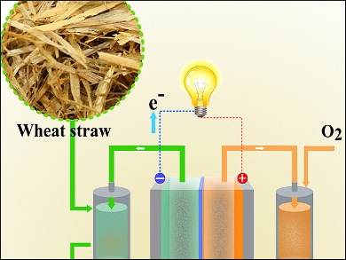
Gasification plants are advanced Waste-to-Energy (WtE) facilities that convert solid fuels—such as municipal solid waste (MSW), biomass, refuse-derived fuel (RDF), or industrial residues—into a combustible gas, commonly called syngas (synthesis gas), through a controlled process of partial oxidation at high temperatures. Unlike conventional incineration or fluidized bed combustion, gasification does not fully combust the fuel in air. Instead, it uses limited oxygen, steam, or air to break down the solid feedstock into a mixture of carbon monoxide (CO), hydrogen (H₂), methane (CH₄), carbon dioxide (CO₂), and small amounts of tars and particulates. The resulting syngas can then be used for electricity generation, heat production, or as a chemical feedstock.
The main advantage of gasification is its ability to produce a clean, energy-dense gas while reducing the formation of pollutants such as dioxins, furans, and nitrogen oxides (NOx) compared to conventional combustion. The process also allows greater flexibility in fuel types and quality, including wet, heterogeneous, or low-calorific waste streams, and supports downstream applications such as combined heat and power (CHP) systems, gas engines, or turbines.
Main parts of a Gasification Plant:
- Waste Reception and Preprocessing: Waste delivered to the plant is received in bunkers or storage areas and undergoes mechanical preprocessing to remove inerts, metals, and oversized items. Shredding, drying, and homogenization ensure uniform particle size and moisture content, which are critical for stable gasification and optimal syngas quality.
- Fuel Feeding System: Preprocessed fuel is conveyed to the gasifier at controlled rates using screw feeders, conveyors, or pneumatic systems. Consistent fuel supply is essential to maintain stable temperature, residence time, and gas composition within the gasification reactor.
- Gasification Reactor: The heart of the plant, the reactor partially oxidizes fuel under high temperature (typically 800–1,200°C) and controlled oxygen supply. Various designs exist, including fixed-bed, fluidized-bed, and entrained-flow gasifiers, each suitable for different feedstock types and applications. The reactor produces syngas, along with solid residues such as ash or char.
- Syngas Cleaning and Cooling: Raw syngas contains particulates, tars, sulfur compounds, and other contaminants. Cleaning systems, including cyclones, scrubbers, filters, and catalytic tar reformers, remove these impurities. Cooling systems reduce gas temperature to levels compatible with engines, turbines, or chemical synthesis processes.
- Energy Conversion Units: Clean syngas can be combusted in gas engines, turbines, or boilers to generate electricity and heat. Alternatively, it can be used as a chemical feedstock for producing hydrogen, methanol, or synthetic fuels.
- Ash and Residue Handling: Solid residues from gasification, including bottom ash or char, are collected and may be processed to recover metals, recycled in construction applications, or disposed of according to environmental regulations.
- Control and Monitoring Systems: Integrated control systems monitor reactor temperature, pressure, oxygen and fuel feed rates, syngas composition, and emissions. Automated adjustments ensure stable gasification, optimal energy recovery, and compliance with environmental standards.
Gasification plants offer high energy efficiency, fuel flexibility, and lower emissions compared to traditional combustion-based WtE systems. They are increasingly adopted for sustainable waste management, renewable energy production, and the generation of versatile energy carriers like syngas or hydrogen.
Waste Reception and Preprocessing
The Waste Reception and Preprocessing stage in a Gasification Plant is the critical first step in ensuring that incoming feedstock is suitable for stable and efficient gasification. Because gasifiers are highly sensitive to fuel size, moisture content, and composition, this stage focuses on conditioning the waste to produce a uniform, high-quality feed for the reactor.
Incoming municipal solid waste (MSW), biomass, refuse-derived fuel (RDF), or industrial residues are delivered to the reception area, typically a tipping floor, bunker, or silo. This area serves as a buffer, allowing the plant to manage fluctuations in waste delivery and maintain a continuous supply to the gasification system. Robust, wear- and fire-resistant structures are used to withstand abrasive and potentially reactive materials, and the area is equipped with ventilation, dust suppression, and odor control systems for environmental safety and worker protection.
Preprocessing operations include mechanical shredding or cutting to reduce particle size, screening to remove oversized or non-combustible items, and magnetic or eddy current separation to recover ferrous and non-ferrous metals. Additional steps may include drying, blending, or homogenization to achieve consistent moisture content, calorific value, and particle distribution. This ensures smooth, predictable operation in the gasification reactor, reduces tar formation, and improves syngas quality.
Automation and monitoring are increasingly integrated into preprocessing systems. Sensors can measure feedstock composition, particle size distribution, and moisture content in real time. This data is used to adjust shredding, screening, or drying parameters automatically, ensuring that the processed fuel meets the specific requirements of the gasifier.
Safety is a central consideration in this stage. Fire detection systems, emergency shutdown mechanisms, and controlled material handling prevent hazards associated with combustible or reactive waste. Enclosed conveyors and negative-pressure ventilation minimize dust emissions, protecting both workers and equipment.
In summary, Waste Reception and Preprocessing in a Gasification Plant ensures that heterogeneous feedstock is properly conditioned, separated, and homogenized for stable, efficient, and safe gasification. It provides a continuous, high-quality fuel supply while supporting environmental protection and operational reliability.
Fuel Feeding System
The Fuel Feeding System in a Gasification Plant is responsible for delivering preprocessed waste to the gasifier at a controlled, continuous rate, ensuring stable reactor operation and consistent syngas production. Proper feeding is essential because fluctuations in fuel supply, particle size, or moisture content can significantly impact gasification efficiency, tar formation, and overall energy recovery.
Preprocessed fuel is typically conveyed from storage silos, bunkers, or hoppers to the gasification reactor using mechanical feeders, screw conveyors, belt feeders, or pneumatic transport systems, depending on the plant configuration and fuel characteristics. For certain high-moisture or heterogeneous fuels, specialized feeding systems such as lock hoppers or hydraulic feeders may be used to prevent bridging, clogging, or backflow while maintaining reactor pressure integrity.
Feed rate control is a central function of the system. Sensors monitor the level of fuel in storage, flow rates, temperature, and sometimes fuel density or calorific value. The plant’s control system uses this data to automatically adjust feeding parameters, maintaining a steady fuel-to-oxidant ratio, appropriate reactor temperature, and optimal residence time for complete gasification. Consistent fuel feeding reduces the risk of tar accumulation, incomplete conversion, or pressure fluctuations in the gasifier.
In multi-fuel or co-gasification plants, the feeding system may include multiple feeders to deliver different fuel types at specific locations in the reactor, enabling optimal mixing, combustion, and syngas composition. Automated sequencing ensures proper timing and proportioning of each fuel stream.
Safety and environmental considerations are integrated into the design. Enclosures, dust extraction systems, and negative-pressure ventilation reduce airborne particulates and odors, while fire detection and emergency shut-off mechanisms protect both personnel and equipment. Anti-bridging devices and vibration systems help maintain consistent material flow and prevent blockages.
In summary, the Fuel Feeding System in a Gasification Plant ensures a continuous, controlled, and safe delivery of preprocessed fuel to the reactor. By maintaining stable feeding, optimizing fuel-to-oxidant ratios, and integrating automated monitoring and safety features, it plays a crucial role in achieving efficient gasification, high-quality syngas production, and reliable plant operation.
Gasification Reactor
The Gasification Reactor is the core component of a Gasification Plant, where preprocessed solid fuels are converted into syngas through a controlled process of partial oxidation at high temperatures. Unlike conventional combustion, which fully burns fuel in excess air, gasification operates under a limited oxygen supply, producing a mixture of combustible gases—primarily carbon monoxide (CO), hydrogen (H₂), methane (CH₄), and carbon dioxide (CO₂)—along with minor amounts of tars, particulates, and char. The reactor’s design and operation directly determine syngas quality, energy yield, and environmental performance.
Reactor types and designs vary depending on feedstock characteristics and desired output. Common configurations include:
- Fixed-bed gasifiers, where fuel rests on a grate and gas flows through the bed. These are simple and robust, suitable for coarse or uniform fuels, but have lower throughput.
- Fluidized-bed gasifiers, which suspend fuel in a bed of inert particles using an upward flow of air or steam, providing uniform temperature distribution, excellent mixing, and stable gas composition.
- Entrained-flow gasifiers, where finely pulverized fuel is injected into a high-temperature oxidizing gas stream, allowing rapid conversion and producing very clean syngas suitable for chemical synthesis.
Operational principles of the gasification reactor involve several stages: drying of the fuel, pyrolysis (thermal decomposition into volatile gases and char), partial oxidation of carbon to CO and CO₂, and reduction reactions that generate H₂ and additional CO. Steam or limited oxygen is introduced in controlled amounts to maintain high temperatures (typically 800–1,200°C) and facilitate efficient conversion while minimizing tar formation and other unwanted byproducts.
Fuel residence time and temperature control are critical. Sensors monitor reactor temperature, pressure, and gas composition in real time, feeding data to the plant’s control system. Automated adjustments to fuel feed rate, oxidant supply, and steam injection maintain stable operation, optimize syngas composition, and prevent bed agglomeration or channeling in fluidized beds.
Ash and char handling is integrated into the reactor design. Solid residues from incomplete fuel conversion accumulate at the bottom or exit through designated ash removal systems. In some configurations, part of the bed material or char may be recycled to improve efficiency and maintain consistent reactor performance.
Pollutant control begins within the reactor. By carefully controlling temperature, oxygen supply, and residence time, formation of nitrogen oxides (NOx), dioxins, and furans is minimized, reducing the load on downstream syngas cleaning systems. Sulfur compounds and other contaminants can be captured in situ using sorbents like lime or limestone in fluidized-bed designs.
In summary, the Gasification Reactor is the central unit where solid fuels are transformed into energy-rich syngas. Its precise design, temperature and feedstock management, and integration with automated monitoring systems are essential for efficient gasification, stable syngas production, and environmentally responsible operation.
Syngas Cleaning and Cooling
The Syngas Cleaning and Cooling System in a Gasification Plant is a critical stage that ensures the raw syngas produced in the gasification reactor is suitable for energy conversion or chemical synthesis. Raw syngas contains particulates, tars, sulfur compounds, ammonia, and other contaminants that can damage engines, turbines, or downstream chemical processes. Cleaning and cooling not only protect equipment but also improve energy efficiency and ensure environmental compliance.
Cooling is typically the first step after the gas exits the reactor. Raw syngas can reach temperatures of 800–1,200°C, depending on the gasifier type and operating conditions. High-temperature heat exchangers or scrubbers reduce the gas temperature to levels compatible with downstream equipment. Waste heat recovery systems may also capture thermal energy from the hot syngas to preheat feedwater, generate steam, or support plant heating, thereby improving overall efficiency.
Particulate removal is performed to eliminate entrained solids, char, and ash. Cyclones, multi-stage cyclones, or electrostatic precipitators are commonly used to separate coarse and fine particles. Effective particulate removal prevents erosion and fouling of turbines, engines, and piping.
Tar removal is a key step because tars—complex hydrocarbons produced during pyrolysis—can condense and clog equipment. Cooling the gas reduces tar condensation in the hot section, while downstream systems such as scrubbers, wet electrostatic precipitators, or catalytic tar reformers remove residual tars. In some advanced plants, catalysts or high-temperature thermal cracking units convert tars into additional syngas, increasing overall energy yield.
Gas cleaning for chemical contaminants involves the removal of sulfur compounds, ammonia, chlorine, and trace metals. Sorbents such as lime, activated carbon, or zinc oxide may be used in dry or wet systems to capture these impurities. Continuous monitoring ensures that concentrations of contaminants meet equipment and environmental specifications.
Moisture and gas composition control are also integral. Excess water vapor can reduce syngas heating value and affect downstream combustion or chemical processes. Condensate removal, gas drying, and filtering systems maintain optimal moisture levels and consistent gas quality.
Automation and monitoring are critical in syngas cleaning and cooling. Sensors measure temperature, pressure, particulate concentration, tar content, and contaminant levels. The plant’s control system adjusts scrubber operation, sorbent injection, and flow rates to ensure that the syngas meets specifications for its intended application, whether combustion in engines, turbines, or chemical synthesis.
In summary, the Syngas Cleaning and Cooling System ensures that the raw gas produced in a gasification reactor is safe, clean, and ready for efficient energy conversion or industrial use. By combining temperature reduction, particulate and tar removal, contaminant scrubbing, and automated monitoring, it protects equipment, optimizes energy recovery, and supports environmentally responsible operation.
Energy Conversion Unit
The Energy Conversion Unit in a Gasification Plant is the stage where cleaned syngas is transformed into usable energy, either in the form of electricity, heat, or combined heat and power (CHP). The design of this unit depends on the intended application of the syngas, the quality and composition of the gas, and the overall efficiency goals of the plant. Proper integration of energy conversion equipment is essential for maximizing energy recovery while minimizing operational issues and emissions.
Syngas combustion in engines or turbines is the most common method for electricity generation. Gas engines, often reciprocating internal combustion engines, are suited for lower-to-medium heating value syngas and can operate efficiently with variable fuel compositions. Gas turbines, on the other hand, require cleaner syngas with higher calorific value but offer higher efficiency and scalability for large-scale power generation. In CHP applications, waste heat from exhaust gases or jacket cooling systems is captured to produce steam or hot water, improving overall plant efficiency.
Boiler-based energy conversion is another approach. Clean syngas can be burned in specialized boilers to generate steam for electricity generation or industrial processes. These systems are particularly suitable when large quantities of heat are needed in addition to electricity. Heat recovery steam generators (HRSG) may also be integrated to capture high-temperature exhaust from gas turbines, further improving thermal efficiency.
Syngas utilization for chemical synthesis is an alternative energy conversion pathway. In some gasification plants, cleaned syngas is used as a feedstock to produce hydrogen, methanol, synthetic natural gas, or other chemicals. This approach adds value beyond energy generation and enables the integration of renewable or waste-derived feedstocks into industrial processes.
Control and monitoring are essential in the Energy Conversion Unit. Sensors monitor temperature, pressure, fuel flow, gas composition, and turbine or engine performance in real time. The plant control system automatically adjusts syngas supply, combustion air, and operational parameters to maintain stable operation, maximize energy output, and minimize pollutant formation.
Safety considerations are integrated throughout the system. Gas detectors, flame monitoring, emergency shutdown mechanisms, and pressure relief devices protect personnel, equipment, and the facility from potential hazards associated with syngas combustion or high-pressure steam generation.
In summary, the Energy Conversion Unit in a Gasification Plant transforms cleaned syngas into electricity, heat, or chemical feedstock. By optimizing combustion, capturing waste heat, and integrating advanced monitoring and safety systems, it ensures efficient, reliable, and environmentally responsible energy production from waste or biomass-derived syngas.
Ash and Residue Handling
The Ash and Residue Handling System in a Gasification Plant is responsible for managing the solid byproducts generated during the gasification process, including bottom ash, char, and any residual unconverted fuel. Proper handling is essential for operational efficiency, environmental compliance, and potential resource recovery. Because gasification does not fully oxidize all solid material, these residues contain a mixture of inert mineral components, unreacted carbon, and occasionally trace metals or other contaminants.
Bottom ash and char removal occurs at the base of the gasification reactor or from dedicated ash hoppers. These solids are typically cooled using water or air quenching systems to prevent dust formation, reduce the risk of fire, and protect downstream handling equipment. In some designs, part of the cooled ash or char can be recycled back into the reactor to maintain thermal balance and improve fuel conversion efficiency.
Processing and recovery steps may include magnetic or eddy current separation to extract ferrous and non-ferrous metals, which can be sent for recycling. Remaining inert materials can be repurposed in construction applications such as road base, concrete aggregates, or other industrial uses, supporting a circular economy approach and reducing landfill disposal requirements.
Handling systems employ enclosed conveyors, screw feeders, hoppers, and silos to transport ash safely from the reactor to storage or disposal points. Pneumatic conveying may also be used for finer residues, ensuring minimal dust emissions and environmental contamination. Continuous monitoring systems track ash flow rates, temperature, and moisture content, feeding data to the plant’s control system for automated adjustment and process optimization.
Safety and environmental considerations are integral. Enclosed systems, dust extraction, and negative-pressure ventilation minimize airborne particulates. Fire detection, temperature monitoring, and emergency shutdown mechanisms protect personnel and equipment. Fly ash or residues with hazardous components, such as heavy metals, are stabilized—often using lime or cement—before secure storage or disposal in compliance with environmental regulations.
In summary, the Ash and Residue Handling System in a Gasification Plant ensures that solid byproducts are safely collected, processed for potential resource recovery, and managed in an environmentally responsible manner. By combining cooling, separation, enclosed transport, and monitoring, it supports continuous operation, protects the environment, and enhances the overall sustainability of the gasification process.
Control and Monitoring Systems
The Control and Monitoring Systems in a Gasification Plant serve as the central management and safety framework, ensuring stable, efficient, and environmentally compliant operation across all stages of fuel handling, gasification, syngas cleaning, and energy conversion. Given the complex chemical and thermal processes involved, as well as the variability of feedstock—including municipal solid waste (MSW), refuse-derived fuel (RDF), biomass, and industrial residues—advanced control systems are essential for optimizing performance and ensuring safe operation.
At the core of the system is a Distributed Control System (DCS) or Supervisory Control and Data Acquisition (SCADA) platform, which continuously collects data from numerous sensors throughout the plant. These sensors monitor parameters such as fuel feed rate, reactor temperature and pressure, oxygen or steam injection, syngas composition, particulate concentration, and energy conversion performance. Real-time data visualization allows operators to monitor the entire plant and respond quickly to abnormal conditions.
Process automation is critical for maintaining stable gasification. The system automatically adjusts fuel feeding, oxidant supply, steam injection, and sorbent dosing based on continuous feedback from the reactor and syngas cleaning units. These adjustments ensure that the gasifier operates within optimal temperature and pressure ranges, producing high-quality syngas while minimizing tar formation, incomplete conversion, or formation of pollutants.
Syngas quality and emissions monitoring are integrated into the control system. Continuous Emission Monitoring Systems (CEMS) measure gases such as CO, CO₂, H₂, NOx, SO₂, and hydrogen sulfide, as well as particulate matter and tars. Automated controls adjust cleaning processes, sorbent injection, or reactor parameters to ensure emissions meet regulatory standards and that syngas is suitable for downstream energy conversion or chemical synthesis.
Safety management is a central feature. The system monitors potential hazards, including high temperatures, overpressure, combustible gas leaks, and equipment malfunctions. Automated emergency shutdowns, fire detection, pressure relief devices, and alarm systems protect personnel, equipment, and the facility. Safety interlocks also prevent improper operation, such as fuel feeding under unsafe conditions or syngas combustion outside of designated units.
Predictive maintenance and diagnostics are increasingly integrated into modern control systems. By analyzing historical and real-time operational data, the system can identify equipment wear, detect anomalies, and schedule maintenance proactively. This reduces downtime, extends equipment life, and improves overall plant reliability.
In summary, the Control and Monitoring Systems in a Gasification Plant provide centralized oversight, process automation, emissions management, and safety protection. They are essential for maintaining stable gasification, ensuring high-quality syngas production, optimizing energy conversion, and achieving continuous, safe, and environmentally responsible plant operation.
Pyrolysis Plants
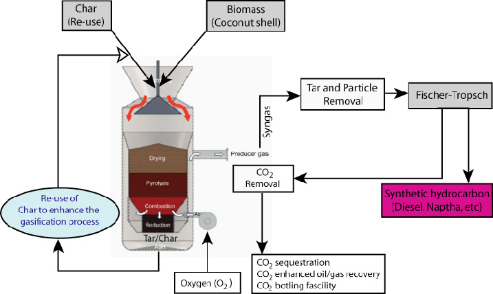
Pyrolysis Plants are advanced waste-to-energy (WtE) or biomass processing facilities that thermochemically decompose organic materials in the absence of oxygen, producing valuable energy carriers such as syngas, pyrolysis oil (bio-oil), and solid char. Unlike conventional incineration or gasification, pyrolysis operates at moderate to high temperatures—typically between 400°C and 800°C—without combustion, allowing the thermal breakdown of complex organic molecules into simpler compounds. Pyrolysis is especially effective for processing municipal solid waste (MSW), plastics, tires, biomass residues, and other carbon-rich feedstocks, converting them into energy-dense products and reducing landfill dependency.
The main advantages of pyrolysis include fuel flexibility, the production of multiple energy streams (syngas, oil, and char), reduced pollutant formation compared to direct combustion, and the potential for downstream chemical or fuel applications. Pyrolysis systems can operate in slow, fast, or flash pyrolysis modes, depending on the heating rate, residence time, and desired product distribution:
- Slow pyrolysis favors char production and is used for solid fuel generation.
- Fast pyrolysis maximizes liquid pyrolysis oil yield for fuel or chemical feedstock.
- Flash pyrolysis emphasizes rapid heating and high gas production for energy applications.
Main parts of a Pyrolysis Plant:
- Waste Reception and Preprocessing: Incoming feedstock is received, stored, and conditioned for uniform particle size, moisture content, and chemical composition. Preprocessing may include shredding, drying, magnetic or eddy current separation, and homogenization to ensure stable pyrolysis reactions and optimal product yield.
- Fuel Feeding System: Preprocessed feedstock is transported at controlled rates to the pyrolysis reactor using screw feeders, conveyors, or pneumatic systems. Precise feeding is essential for maintaining stable temperature, residence time, and product distribution.
- Pyrolysis Reactor: The reactor is the heart of the plant, where feedstock is thermally decomposed in an oxygen-free environment. Depending on the design, reactors can be rotary kilns, fluidized beds, auger-type, or moving beds. Temperature, heating rate, and residence time are carefully controlled to maximize the desired product (syngas, oil, or char).
- Product Recovery Systems: Pyrolysis generates multiple products—syngas, pyrolysis oil, and solid char. Syngas is cooled and cleaned for combustion or energy generation. Pyrolysis oil is condensed and collected for use as a fuel or chemical feedstock. Char is separated, cooled, and may be used as a solid fuel, soil amendment, or carbon material.
- Syngas Cleaning and Cooling: Raw syngas contains particulates, tars, and other contaminants. Multi-stage cleaning systems, including cyclones, filters, scrubbers, and condensers, remove impurities and adjust temperature for downstream energy conversion.
- Energy Conversion Units: Cleaned syngas and pyrolysis oil can be used in gas engines, turbines, or boilers to generate electricity and heat. Combined heat and power (CHP) configurations can further improve energy efficiency.
- Char and Residue Handling: Solid char and residual ash are collected, cooled, and stored. Depending on composition, char can be sold as a fuel or processed for chemical or agricultural applications. Residual inerts are disposed of in an environmentally responsible manner.
- Control and Monitoring Systems: Advanced control systems monitor reactor temperature, pressure, feed rate, product flow, syngas composition, and emissions. Automated adjustments optimize pyrolysis conditions, ensure safety, and maintain regulatory compliance.
Pyrolysis plants are particularly valued for their ability to convert heterogeneous or high-moisture waste into multiple energy carriers with reduced emissions, high fuel efficiency, and potential for chemical feedstock recovery. They are increasingly used for sustainable waste management, renewable energy production, and resource recovery from plastics, tires, biomass, and other organic waste streams.
Waste Reception and Preprocessing
The Waste Reception and Preprocessing stage in a Pyrolysis Plant is the first and one of the most critical steps, ensuring that incoming feedstock is suitable for efficient and stable thermal decomposition in the pyrolysis reactor. Because pyrolysis performance and product distribution are highly sensitive to feedstock characteristics, this stage focuses on conditioning waste to achieve uniform particle size, moisture content, and chemical composition.
Incoming municipal solid waste (MSW), plastics, tires, biomass, or industrial residues are delivered to a reception area, which typically consists of a tipping floor, storage bunker, or silo. This area acts as a buffer, allowing the plant to manage fluctuations in waste delivery while maintaining a continuous feed to the reactor. The structures are designed with wear- and fire-resistant materials to withstand abrasive or combustible materials, and they include ventilation, dust suppression, and odor control systems for environmental safety and worker protection.
Preprocessing operations may include:
- Shredding or cutting to reduce particle size and improve heat transfer during pyrolysis.
- Screening to remove oversized items, non-combustible materials, or contaminants.
- Magnetic or eddy current separation to extract ferrous and non-ferrous metals, which can be recycled.
- Drying or moisture adjustment to achieve consistent feedstock moisture levels, which is critical for controlling pyrolysis temperature, reaction rates, and product yield.
- Blending or homogenization to ensure a uniform mixture, especially important when feedstock consists of heterogeneous materials such as mixed waste streams.
Automation and monitoring are increasingly integrated into preprocessing systems. Sensors can measure particle size, moisture content, and feedstock composition in real time. Data from these sensors allow the plant control system to automatically adjust shredding, screening, or drying operations, ensuring that the conditioned feed meets the reactor’s specifications.
Safety considerations are integral to this stage. Fire detection systems, emergency shutdown mechanisms, and controlled material handling prevent hazards associated with combustible or reactive waste. Enclosed conveyors, negative-pressure ventilation, and dust extraction minimize airborne particulates and odors, protecting both personnel and equipment.
In summary, Waste Reception and Preprocessing in a Pyrolysis Plant ensures that diverse feedstock is properly conditioned, separated, and homogenized for efficient and stable pyrolysis. This stage provides a continuous, high-quality fuel supply to the reactor, supports operational reliability, and maintains environmental safety standards.
Fuel Feeding System
The Fuel Feeding System in a Pyrolysis Plant is responsible for transporting preprocessed feedstock from storage to the pyrolysis reactor at a controlled and continuous rate. Proper feeding is essential because fluctuations in fuel supply, particle size, or moisture content can significantly affect reactor temperature, reaction kinetics, and the distribution of pyrolysis products—syngas, bio-oil, and char.
Preprocessed feedstock is typically delivered from storage bunkers, silos, or hoppers using screw feeders, belt conveyors, pneumatic feeders, or auger systems, depending on the type and consistency of the material. For high-moisture or heterogeneous feedstock, specialized feeders may be employed to prevent bridging, clogging, or backflow while maintaining reactor pressure integrity, especially in sealed or pressurized pyrolysis reactors.
Feed rate control is critical for stable pyrolysis operation. Sensors monitor feedstock levels, flow rates, moisture content, and sometimes calorific value. These readings are sent to the plant’s control system, which automatically adjusts feeder speed, conveyor rate, or injection timing to maintain optimal thermal conditions in the reactor. Consistent feeding prevents temperature fluctuations, excessive tar formation, or incomplete thermal decomposition.
In plants handling multiple types of feedstock, the system may include parallel feeders or metering devices to proportion different materials precisely. This allows co-pyrolysis of various wastes and optimization of product yields. Automated sequencing and real-time adjustments ensure stable and predictable operation.
Safety and environmental controls are integrated throughout the feeding system. Enclosed conveyors, dust extraction, and negative-pressure ventilation reduce airborne particulates and odors, while fire detection, emergency shutdown mechanisms, and anti-bridging devices protect personnel and equipment.
In summary, the Fuel Feeding System in a Pyrolysis Plant ensures the continuous, controlled, and safe delivery of preprocessed feedstock to the reactor. By maintaining stable feed rates, optimizing fuel distribution, and integrating automated monitoring and safety features, it supports efficient pyrolysis, high-quality product yields, and reliable plant operation.
Pyrolysis Reactor
The Pyrolysis Reactor is the core unit of a Pyrolysis Plant, where preprocessed feedstock undergoes thermal decomposition in an oxygen-free environment to produce syngas, pyrolysis oil (bio-oil), and solid char. Unlike combustion, which fully oxidizes fuel, pyrolysis relies on heat to break down complex organic molecules into simpler, energy-rich compounds. The reactor’s design, temperature control, and residence time directly influence product yield, quality, and overall process efficiency.
Reactor types and designs vary based on feedstock, desired product distribution, and plant scale:
- Rotary Kiln Reactors: Cylindrical, slowly rotating vessels that allow continuous mixing and uniform heating, suitable for heterogeneous feedstock such as municipal solid waste or plastics.
- Fluidized-Bed Reactors: Use a fluidized bed of inert particles to suspend and uniformly heat fine feedstock, providing excellent temperature control and high reaction rates, ideal for biomass or shredded waste.
- Auger or Screw Reactors: Mechanically convey feedstock through a heated chamber, allowing controlled residence time and good heat transfer, suitable for moderate throughput and consistent particle sizes.
- Batch or Moving-Bed Reactors: Often used for slow pyrolysis applications, optimizing char production or laboratory-scale operations.
Operational principles involve several stages:
- Drying: Moisture in the feedstock is evaporated to prepare for thermal decomposition.
- Pyrolysis (Thermal Cracking): Organic material decomposes into volatiles, tars, gases, and solid char.
- Volatile Collection and Condensation: Gaseous products are partially condensed to recover pyrolysis oil, while remaining gases form syngas.
Temperature and residence time control are critical for product optimization. For example, higher temperatures and rapid heating favor syngas production, while slower heating at moderate temperatures favors char and bio-oil formation. Sensors continuously monitor reactor temperature, pressure, and material flow, feeding data to the control system for automated adjustments of heating rate, feedstock input, and reactor environment.
In-situ tar and contaminant management may be integrated, especially in fluidized-bed designs, where sorbents or catalytic surfaces can reduce tar formation and capture harmful compounds during pyrolysis.
Solid residue management is also incorporated into the reactor design. Char and inorganic ash accumulate at the reactor base and are removed through cooling hoppers or conveyors for downstream processing, recycling, or safe disposal.
In summary, the Pyrolysis Reactor is the central unit where controlled thermal decomposition of feedstock occurs. Its design, heating strategy, and operational control directly influence the quality and yield of syngas, pyrolysis oil, and char, making it the key determinant of efficiency, reliability, and environmental performance in a Pyrolysis Plant.
Product Recovery Systems
The Product Recovery Systems in a Pyrolysis Plant are responsible for capturing, separating, and collecting the valuable outputs produced in the pyrolysis reactor—syngas, pyrolysis oil (bio-oil), and solid char—while ensuring safe handling and maintaining product quality. Effective recovery is essential for maximizing energy yield, minimizing losses, and enabling subsequent energy conversion or chemical utilization.
Syngas recovery involves routing the hot gaseous stream from the pyrolysis reactor to cooling and cleaning units. Raw syngas contains particulates, tars, and condensable vapors that must be removed before it can be used in engines, turbines, boilers, or chemical synthesis processes. Multi-stage systems—including cyclones, filters, scrubbers, and condensers—remove impurities and adjust temperature, ensuring that the syngas meets specifications for energy conversion or downstream processing.
Pyrolysis oil recovery is achieved by condensing volatile organics in the gas stream. As the hot gas cools, bio-oil vapors condense into liquid form and are collected in condensers or storage tanks. Some systems employ multi-stage condensation or electrostatic precipitators to capture a higher fraction of condensable organics. The recovered pyrolysis oil can be used as a fuel for boilers or engines, or as a chemical feedstock for producing renewable chemicals and fuels.
Solid char and ash collection is integrated into the reactor and post-reactor handling system. Char is removed via cooled hoppers, screw conveyors, or rotary valves, and may be further processed for use as a solid fuel, activated carbon, or soil amendment. Residual ash and inorganic materials are separated from char and stored or disposed of in compliance with environmental regulations.
Product quality control is an essential aspect of recovery. Sensors and sampling points monitor syngas composition, pyrolysis oil density, acidity, and water content, as well as char properties such as moisture and fixed carbon content. This data allows operators to adjust reactor parameters or recovery conditions to optimize yields and maintain product consistency.
Safety and environmental considerations are integrated throughout the system. Enclosures, dust extraction, and negative-pressure ventilation minimize emissions of particulates, volatile compounds, and odors. Temperature monitoring, pressure control, and fire detection systems prevent hazards associated with combustible syngas and pyrolysis oil vapors.
In summary, the Product Recovery Systems in a Pyrolysis Plant efficiently capture and separate syngas, pyrolysis oil, and solid char, ensuring high-quality outputs for energy or chemical use. By combining cooling, condensation, filtration, and automated monitoring, these systems maximize energy yield, protect equipment, and support environmentally responsible operation.
Syngas Cleaning and Cooling
The Syngas Cleaning and Cooling System in a Pyrolysis Plant is a crucial stage that ensures the raw gas produced in the pyrolysis reactor is safe, clean, and suitable for energy conversion or chemical applications. Raw syngas typically contains particulates, tars, condensable organics, sulfur compounds, ammonia, and other contaminants that can damage engines, turbines, boilers, or downstream chemical synthesis equipment. Proper cleaning and cooling improve energy efficiency, protect equipment, and maintain environmental compliance.
Cooling is the first step after the gas exits the reactor. Raw syngas can reach temperatures of 400–800°C depending on reactor type and operating conditions. Heat exchangers, condensers, or scrubbers reduce the gas temperature to levels compatible with downstream systems. Heat recovery is often integrated, using the hot gas to generate steam or preheat feedstock, which enhances overall plant efficiency.
Particulate removal is performed to eliminate char, ash, and other solid residues carried with the gas. Cyclones, multi-stage cyclones, or fabric filters are commonly used to separate coarse and fine particles. Efficient particulate removal prevents erosion, fouling, and clogging of turbines, engines, piping, and other equipment.
Tar removal is a key process in pyrolysis gas cleaning because tars—complex hydrocarbons—can condense and block pipelines or damage energy conversion equipment. Cooling the gas reduces tar condensation in upstream ducts, while scrubbers, wet electrostatic precipitators, or catalytic tar reformers remove remaining tar. Some advanced systems thermally crack or catalytically reform tars into additional syngas, improving energy yield.
Contaminant removal targets sulfur compounds, ammonia, chlorine, and trace metals. Dry or wet scrubbers and sorbents such as lime, activated carbon, or zinc oxide capture these impurities. Continuous monitoring ensures that gas meets specifications for calorific value and contaminant levels for its intended use.
Moisture and gas composition control is also critical. Excess water vapor can lower syngas heating value and affect downstream combustion or synthesis processes. Condensate removal, gas drying, and filtering maintain optimal moisture levels and consistent gas quality.
Automation and monitoring are integral to the cleaning and cooling stage. Sensors continuously measure temperature, pressure, particulate concentration, tar content, and contaminant levels. The plant control system adjusts scrubber operation, sorbent dosing, and flow rates to ensure syngas quality, protect equipment, and maintain regulatory compliance.
In summary, the Syngas Cleaning and Cooling System in a Pyrolysis Plant ensures that raw gas is safe, clean, and suitable for energy conversion or chemical applications. By combining cooling, particulate and tar removal, contaminant scrubbing, and automated monitoring, it maximizes energy recovery, protects equipment, and supports environmentally responsible plant operation.
Energy Conversion Units
The Energy Conversion Units in a Pyrolysis Plant are responsible for transforming the clean syngas and, in some cases, pyrolysis oil into usable energy in the form of electricity, heat, or combined heat and power (CHP). Proper design and integration of these units are essential for maximizing energy recovery, ensuring stable operation, and minimizing emissions, while enabling flexible use of multiple pyrolysis products.
Syngas utilization is the primary method of energy conversion. Clean syngas can be combusted in gas engines, gas turbines, or specialized boilers:
- Gas engines (reciprocating internal combustion engines) are suitable for medium-scale plants and can handle variations in gas composition. They are often coupled with CHP systems to simultaneously produce electricity and thermal energy.
- Gas turbines are better suited for larger plants with high-quality, low-tar syngas. Turbines offer higher electrical efficiency and can be integrated with heat recovery steam generators (HRSG) to capture waste heat for steam production.
- Syngas-fired boilers convert the chemical energy into steam for electricity generation or industrial processes, particularly when heat demand is significant.
Pyrolysis oil utilization is an additional energy pathway in some plants. The liquid bio-oil can be burned in specialized burners, furnaces, or boilers to generate heat or steam, either standalone or in combination with syngas, improving flexibility and overall energy efficiency.
Combined Heat and Power (CHP) configurations maximize energy recovery by utilizing both electricity and process heat. Waste heat from syngas combustion, engines, or turbines is captured to generate steam or hot water for industrial processes, district heating, or reactor preheating, significantly improving overall plant efficiency.
Control and monitoring are essential for stable and safe operation. Sensors track syngas flow, composition, calorific value, temperature, and pressure, as well as engine, turbine, or boiler performance. The plant’s control system automatically adjusts fuel supply, air/fuel ratios, and operational parameters to maintain optimal efficiency and minimize pollutant formation.
Safety considerations are integrated throughout the energy conversion stage. Gas leak detectors, flame monitoring, emergency shutdown systems, pressure relief devices, and fire detection mechanisms protect personnel, equipment, and the facility from hazards associated with combustible gases and pyrolysis oil.
In summary, the Energy Conversion Units in a Pyrolysis Plant efficiently transform cleaned syngas and pyrolysis oil into electricity, heat, or combined power. By optimizing combustion, capturing waste heat, and integrating advanced monitoring and safety systems, these units ensure high energy recovery, operational reliability, and environmentally responsible plant performance.
Char and Residue Handling
The Char and Residue Handling System in a Pyrolysis Plant manages the solid byproducts generated during the thermal decomposition of feedstock, including char, ash, and any unconverted residual materials. Proper handling of these solids is essential for operational efficiency, safety, environmental compliance, and potential resource recovery.
Char removal is integrated into the pyrolysis reactor design. Solid char accumulates at the base or along the reactor exit and is extracted through cooled hoppers, screw conveyors, or rotary valves. Cooling is often applied using air or water quenching to prevent spontaneous combustion, reduce dust formation, and protect downstream handling equipment.
Processing and recovery of char depends on its intended use. High-carbon char can be used as a solid fuel, while other grades may be processed into activated carbon, soil amendments, or carbon-based industrial products. Residual ash or inorganic material is separated from the char and stored or disposed of in compliance with environmental regulations. Some facilities implement magnetic or eddy current separation to recover metals from char or ash for recycling.
Conveying and storage systems ensure safe transport of char and residues. Enclosed screw conveyors, hoppers, and silos, often combined with dust extraction and negative-pressure ventilation, minimize airborne particulates and odors. Continuous monitoring of temperature, moisture, and flow rate allows operators to maintain consistent handling conditions and prevent hazards.
Safety and environmental measures are critical. Fire detection, temperature monitoring, and emergency shutdown systems reduce the risk of combustion or dust explosions. Proper containment and handling ensure that residual ash or char does not contaminate the environment or pose health risks.
In summary, the Char and Residue Handling System in a Pyrolysis Plant ensures the safe collection, cooling, transport, and processing of solid byproducts. By combining efficient extraction, product recovery, environmental controls, and safety measures, it supports continuous plant operation, maximizes resource utilization, and maintains environmentally responsible waste management.
Control and Monitoring Systems
The Control and Monitoring Systems in a Pyrolysis Plant serve as the central operational framework, ensuring stable, efficient, and safe performance across all stages of feedstock handling, pyrolysis, product recovery, and energy conversion. Given the variability of feedstock—including municipal solid waste, plastics, tires, and biomass residues—and the complex thermal and chemical processes involved, advanced control systems are essential for optimizing performance, maintaining product quality, and ensuring environmental compliance.
At the heart of the system is a Distributed Control System (DCS) or Supervisory Control and Data Acquisition (SCADA) platform that continuously collects and analyzes data from sensors throughout the plant. Parameters monitored include reactor temperature, pressure, feedstock flow rate, syngas composition, pyrolysis oil flow, char output, particulate and tar levels, and emissions. Real-time data visualization allows operators to maintain complete oversight of plant operations and respond rapidly to deviations.
Process automation ensures consistent operation. The control system adjusts feedstock input, heating rates, reactor temperature, and product recovery parameters automatically to maintain optimal pyrolysis conditions. This precise control prevents temperature fluctuations, excessive tar formation, incomplete decomposition, or reactor fouling, directly improving syngas, pyrolysis oil, and char quality.
Syngas and emissions monitoring is integrated into the control system. Continuous sensors measure concentrations of CO, CO₂, H₂, NOx, SO₂, tars, and particulate matter. Automated feedback adjusts gas cleaning systems, condensers, and reactor parameters to meet regulatory standards and ensure safe downstream energy conversion or chemical utilization.
Safety management is a central function. The system monitors potential hazards such as high temperatures, overpressure, combustible gas leaks, and equipment malfunctions. Emergency shutdown mechanisms, fire detection, pressure relief devices, and alarms protect personnel, equipment, and the facility. Interlocks prevent unsafe operations, such as feeding fuel when reactor conditions are unsuitable or syngas combustion outside designated units.
Predictive maintenance and diagnostics are increasingly incorporated. By analyzing operational trends and real-time sensor data, the system can detect equipment wear, identify anomalies, and schedule preventive maintenance, reducing unplanned downtime and extending equipment lifespan.
In summary, the Control and Monitoring Systems in a Pyrolysis Plant provide centralized oversight, automation, emissions management, and safety protection. They ensure stable reactor operation, high-quality product recovery, efficient energy conversion, and compliance with environmental standards, making them essential for reliable, safe, and environmentally responsible pyrolysis plant operation.
Anaerobic Digestion (Biogas Plants)
Anaerobic Digestion (AD) or Biogas Plants are specialized facilities designed to convert organic waste into renewable energy in the form of biogas, a mixture primarily composed of methane (CH₄) and carbon dioxide (CO₂), through the biological breakdown of organic matter in an oxygen-free environment. These plants are widely used to treat agricultural residues, manure, food waste, municipal organic waste, and industrial organic streams, while simultaneously producing nutrient-rich digestate that can be used as fertilizer. Anaerobic digestion offers a sustainable waste management solution by reducing landfill use, lowering greenhouse gas emissions, and generating renewable energy.
The process involves a complex microbial ecosystem where bacteria sequentially degrade organic compounds through four main stages:
- Hydrolysis, breaking down complex polymers (carbohydrates, proteins, fats) into soluble monomers.
- Acidogenesis, converting monomers into volatile fatty acids, alcohols, hydrogen, and CO₂.
- Acetogenesis, transforming intermediate products into acetate, hydrogen, and CO₂.
- Methanogenesis, where methanogenic archaea produce methane and carbon dioxide, forming biogas.
Main parts of an Anaerobic Digestion (Biogas) Plant:
- Feedstock Reception and Storage: Organic materials are received, weighed, and stored in silos, tanks, or bunkers. Storage is designed to maintain feedstock quality, prevent odor emissions, and allow controlled feeding to digesters.
- Preprocessing Systems: Feedstock may be mechanically shredded, pulped, or diluted to achieve uniform particle size and consistency, improving microbial digestion efficiency. Contaminants such as plastics, stones, or metals are removed through screening, sieving, or magnetic separation.
- Feedstock Feeding System: Preprocessed feedstock is continuously or intermittently delivered into anaerobic digesters via pumps, screw conveyors, or pipelines. Controlled feeding ensures stable microbial activity, optimal digestion, and consistent biogas production.
- Anaerobic Digesters: Digesters are sealed, oxygen-free tanks where microbial breakdown occurs. Designs include continuously stirred tank reactors (CSTRs), plug-flow digesters, or batch reactors, depending on feedstock type and scale. Temperature (mesophilic 30–40°C or thermophilic 50–60°C), pH, and retention time are closely monitored to optimize microbial activity and biogas yield.
- Biogas Collection and Storage: Produced biogas is collected from the headspace of digesters and stored in gas holders or pressurized tanks. Storage systems accommodate fluctuations in gas production and supply, ensuring continuous energy availability.
- Biogas Cleaning and Upgrading: Raw biogas contains impurities such as hydrogen sulfide (H₂S), ammonia, siloxanes, and moisture. Cleaning systems—using scrubbers, filters, or chemical absorbers—remove contaminants, making the gas suitable for combustion in engines, turbines, or boilers. Upgrading systems can further enrich methane content to produce biomethane for injection into natural gas grids or as vehicle fuel.
- Energy Conversion Units: Clean biogas or biomethane is converted into electricity, heat, or combined heat and power (CHP) using gas engines, turbines, or boilers. Some plants also use biogas as a fuel for industrial processes or as a substitute for natural gas.
- Digestate Handling and Storage: After digestion, nutrient-rich digestate is separated into solid and liquid fractions. Solids can be used as soil amendments or fertilizers, while liquids are treated or applied as liquid fertilizer. Proper handling prevents odors, nutrient loss, and environmental contamination.
- Control and Monitoring Systems: Modern AD plants integrate advanced automation to monitor feedstock input, digester temperature, pH, biogas production, composition, and energy output. Safety systems detect gas leaks, overpressure, or abnormal conditions and trigger alarms or emergency shutdowns.
In summary, Anaerobic Digestion (Biogas) Plants convert organic waste into renewable energy and valuable byproducts through controlled microbial processes. By integrating feedstock preprocessing, optimized digestion, biogas cleaning, energy conversion, and digestate management, these plants provide a sustainable solution for waste treatment, renewable energy production, and nutrient recycling.
Feedstock Reception and Storage
The Feedstock Reception and Storage stage in an Anaerobic Digestion (Biogas) Plant is the first step in ensuring a continuous and efficient digestion process. It is designed to receive, weigh, temporarily store, and manage organic waste before it is fed into the anaerobic digesters. Proper handling at this stage is critical for maintaining feedstock quality, preventing contamination, and ensuring stable biogas production.
Reception areas typically include tipping floors for municipal or industrial organic waste, loading docks for agricultural residues or manure, and dedicated silos or tanks for liquid feedstocks. Incoming materials are weighed, inspected, and classified to determine suitability for digestion. Non-organic contaminants such as plastics, metals, stones, or inert debris are identified and removed to prevent damage to downstream equipment and ensure efficient microbial digestion.
Storage facilities are designed to buffer fluctuations in feedstock delivery and allow continuous feeding into the digesters. Solid feedstock may be stored in bunkers, silos, or covered piles, while liquid or slurry feedstock is stored in tanks or lagoons. Storage systems are engineered to minimize odor emissions, reduce the risk of spoilage, and maintain optimal moisture and temperature conditions for microbial activity.
Environmental and safety controls are integral to this stage. Negative-pressure ventilation, biofilters, or scrubbers reduce odor emissions. Enclosures, sloped floors, and automated cleaning systems prevent contamination and maintain hygiene. Fire detection and monitoring systems may also be included, particularly in plants handling dry or fibrous feedstock.
Monitoring and automation enhance operational efficiency. Sensors can track storage levels, feedstock temperature, moisture content, and composition. Data is relayed to the plant’s control system to optimize feedstock feeding schedules and maintain consistent digester performance.
In summary, Feedstock Reception and Storage in a Biogas Plant ensures that organic waste is properly received, inspected, conditioned, and stored to provide a reliable and high-quality supply to the digesters. By integrating contaminant removal, environmental controls, and automated monitoring, this stage supports stable microbial digestion, efficient biogas production, and safe, environmentally responsible plant operation.
Preprocessing Systems
The Preprocessing Systems in an Anaerobic Digestion (Biogas) Plant are designed to condition and prepare feedstock for efficient microbial digestion. Since feedstock can vary widely—ranging from agricultural residues, manure, and food waste to industrial organic streams—preprocessing ensures uniformity in particle size, consistency, and moisture content, which are critical for stable digestion, optimal biogas production, and reduced operational issues.
Key preprocessing operations include:
- Shredding or grinding: Solid feedstocks are mechanically reduced in size to increase surface area, improving microbial access and accelerating digestion. Shredding also helps prevent clogging in feed lines and digesters.
- Pulping or homogenization: Mixed or heterogeneous waste streams, such as food waste or slurry, are blended to create a uniform consistency, ensuring even digestion and stable biogas yield.
- Dilution or moisture adjustment: Liquid or slurry feedstocks may be diluted with water or process liquids to achieve optimal moisture content. This is critical for maintaining proper viscosity, pumping efficiency, and microbial activity in the digesters.
- Screening and contaminant removal: Mechanical screens, sieves, and magnetic separators remove non-biodegradable contaminants such as plastics, metals, stones, or glass, protecting pumps, valves, and digesters from damage.
- Heat treatment or pasteurization (optional): In some plants, feedstock is thermally treated to reduce pathogens and improve safety, particularly when using municipal or agricultural waste intended for digestate application.
Automation and monitoring enhance preprocessing efficiency. Sensors measure particle size, moisture content, and consistency in real time, enabling automated adjustments to shredders, mixers, and pumps. This ensures that feedstock meets the specifications required for optimal digester performance.
Environmental and safety considerations are integral. Enclosed conveyors, dust extraction, and negative-pressure ventilation minimize odor and airborne particulates. Safety interlocks and emergency shutdown mechanisms protect operators and equipment from hazards associated with mechanical processing of organic waste.
In summary, Preprocessing Systems in a Biogas Plant prepare organic feedstock for efficient anaerobic digestion by reducing particle size, homogenizing materials, adjusting moisture, and removing contaminants. Through a combination of mechanical, hydraulic, and sometimes thermal treatments, these systems support stable microbial activity, maximize biogas yield, and maintain safe and environmentally responsible plant operation.
Feedstock Feeding System
The Feedstock Feeding System in an Anaerobic Digestion (Biogas) Plant is responsible for delivering preprocessed organic material into the digesters at a controlled and consistent rate. Proper feeding is essential to maintain stable microbial activity, optimize biogas production, and prevent operational disturbances such as overloading, acidification, or clogging in the digestion process.
Feeding mechanisms vary depending on feedstock type, digester design, and plant scale. Common methods include:
- Pumps and pipelines: Used primarily for liquid or slurry feedstock, allowing precise volumetric control and continuous feeding into pressurized or continuously stirred tank reactors (CSTRs).
- Screw or auger conveyors: Suitable for semi-solid or thick slurry feedstocks, providing controlled transfer from storage tanks or preprocessing units to the digester inlet.
- Batch feeders: In batch or plug-flow digesters, feedstock is loaded periodically using hoppers, conveyors, or hydraulic systems. This allows complete filling and controlled retention time for each batch.
Flow rate and feed consistency are carefully monitored to ensure that digesters maintain optimal temperature, pH, and organic loading rates. Sensors track feedstock flow, solids content, and composition, and the data is used by the plant’s control system to adjust pumps, conveyor speeds, or batch feeding intervals. This prevents sudden spikes or drops in organic loading, which could disrupt microbial activity or reduce biogas yield.
Safety and environmental measures are integral to feeding systems. Enclosed transfer lines and negative-pressure ventilation prevent odor emissions and minimize exposure to gases or particulates. Anti-blocking devices and flow sensors help avoid feedline clogging, while emergency shutdowns and interlocks protect operators and equipment from hazards.
Integration with control systems allows automated synchronization between feedstock storage, preprocessing, and digester operation. This ensures continuous or appropriately timed feeding, optimizing digestion efficiency and biogas production.
In summary, the Feedstock Feeding System in a Biogas Plant ensures the continuous, controlled, and safe delivery of preprocessed organic material into anaerobic digesters. By maintaining consistent feed rates, monitoring composition, and integrating safety measures, the system supports stable microbial activity, maximizes biogas yield, and contributes to reliable, efficient, and environmentally responsible plant operation.
Anaerobic Digesters
Anaerobic Digesters are the core units of a Biogas Plant, where organic feedstock undergoes controlled microbial decomposition in the absence of oxygen to produce biogas and nutrient-rich digestate. These digesters provide a stable, sealed environment optimized for microbial activity, enabling efficient conversion of complex organic matter into methane, carbon dioxide, and minor byproducts. The design and operational parameters of the digesters directly influence biogas yield, composition, and process stability.
Types of Anaerobic Digesters:
- Continuously Stirred Tank Reactors (CSTRs): Homogenize feedstock through mechanical or hydraulic mixing, ensuring uniform microbial activity and temperature distribution. CSTRs are widely used for liquid and semi-solid feedstocks such as manure, slurry, or food waste.
- Plug-Flow Digesters: Feedstock moves gradually through a long, insulated channel, allowing sequential digestion. This design is suitable for high-solids content materials like agricultural residues and produces a predictable biogas profile.
- Batch Digesters: Operate on a fill-and-digest principle, where a defined volume of feedstock is processed over a set period. After digestion, the reactor is emptied and refilled with a new batch. This type is often used for smaller plants or specialized feedstocks.
- Covered Lagoon or Tank Digesters: Used for dilute slurry or manure, these large, insulated lagoons are covered to capture biogas and provide mesophilic temperature conditions.
Operational parameters are critical for efficient digestion:
- Temperature: Digesters operate in mesophilic (30–40°C) or thermophilic (50–60°C) ranges. Mesophilic conditions offer stability and lower energy input, while thermophilic conditions provide faster digestion and higher pathogen reduction.
- Retention time: The duration feedstock remains in the digester affects the extent of digestion. Depending on feedstock composition and digester type, hydraulic retention time (HRT) typically ranges from 15 to 40 days.
- pH and alkalinity: Maintaining pH between 6.8 and 7.5 ensures optimal microbial activity and prevents acidification, which can inhibit methane production.
- Mixing: Continuous or intermittent mixing promotes uniform temperature and nutrient distribution, prevents scum or sediment buildup, and enhances biogas yield.
Safety and monitoring systems are integrated into digesters. Sensors track temperature, pressure, pH, biogas production, and composition, providing data for automated control systems. Overpressure relief valves, gas detectors, and emergency shutdown mechanisms protect personnel and equipment from hazards such as gas accumulation, overpressure, or foaming events.
Digestate management is often integrated with the digester outlet. Solid and liquid fractions are separated, cooled, and stored for safe handling or use as fertilizer, ensuring nutrient recovery and environmental compliance.
In summary, Anaerobic Digesters are the heart of a Biogas Plant, providing a controlled, oxygen-free environment for microbial decomposition of organic feedstock. By optimizing temperature, retention time, mixing, and pH, and integrating advanced monitoring and safety systems, digesters maximize biogas production, stabilize feedstock processing, and support safe, efficient, and environmentally responsible plant operation.
Biogas Collection and Storage
The Biogas Collection and Storage System in an Anaerobic Digestion (Biogas) Plant is responsible for capturing, containing, and regulating the biogas produced in the digesters, ensuring a continuous and safe supply for energy conversion or further processing. Proper collection and storage are essential to maintain gas quality, prevent losses, and minimize safety and environmental risks.
Biogas collection begins at the headspace of the anaerobic digesters, where methane-rich gas accumulates. Gas-tight covers or domes, often flexible or rigid, seal the digesters to prevent oxygen ingress and gas escape. Gas collection piping, usually made of corrosion-resistant materials such as stainless steel or coated steel, transports biogas from the digester to storage or processing units. Valves, pressure regulators, and flow meters are integrated along the piping to control flow rates, maintain system pressure, and monitor gas production.
Biogas storage accommodates fluctuations in production and consumption, ensuring a steady supply to energy conversion units such as engines, turbines, or boilers. Storage systems can be:
- Flexible gas holders: Inflatable membranes or bladders that expand and contract as gas volume changes, commonly used in smaller or medium-scale plants.
- Fixed dome storage tanks: Rigid, sealed domes built above digesters or separate tanks, often used in large-scale plants for long-term storage and pressure stability.
- Pressurized tanks: High-pressure vessels for biomethane storage after upgrading, suitable for injection into natural gas grids or as vehicle fuel.
Gas quality and safety are critical. Biogas contains methane, carbon dioxide, water vapor, hydrogen sulfide, and trace contaminants. Water condensate is removed using separators or traps to prevent corrosion and blockages. Hydrogen sulfide is often scrubbed or chemically treated to reduce corrosiveness and odor. Pressure relief valves, flame arrestors, gas detectors, and emergency shutdown systems prevent overpressure, leaks, or accidental ignition, ensuring personnel and equipment safety.
Monitoring and automation enhance system reliability. Sensors continuously measure gas pressure, flow, composition, and temperature. The control system adjusts gas collection rates, storage pressures, and supply to downstream energy units, maintaining consistent performance and optimizing energy recovery.
In summary, the Biogas Collection and Storage System in an Anaerobic Digestion Plant efficiently captures and stores methane-rich gas while maintaining quality, safety, and operational stability. Through sealed digesters, controlled piping, pressure-regulated storage, and integrated monitoring, the system ensures reliable energy supply, prevents environmental emissions, and supports safe, efficient, and environmentally responsible plant operation.
Biogas Cleaning and Upgrading
The Biogas Cleaning and Upgrading System in an Anaerobic Digestion (Biogas) Plant is responsible for removing impurities from raw biogas and, when required, enriching its methane content to produce high-quality biogas or biomethane suitable for energy conversion, injection into natural gas grids, or use as vehicle fuel. Raw biogas contains methane (CH₄), carbon dioxide (CO₂), water vapor, hydrogen sulfide (H₂S), ammonia, siloxanes, and trace contaminants that must be treated to prevent equipment corrosion, improve calorific value, and comply with environmental standards.
Cleaning processes include:
- Moisture removal: Water vapor condenses as biogas cools and can cause corrosion, pipeline blockages, and reduced energy efficiency. Moisture is removed using condensers, dehydration units, or silica gel dryers.
- Hydrogen sulfide removal: H₂S is corrosive and toxic. It can be removed using chemical scrubbers, iron-based absorbents, activated carbon filters, or biofilters.
- Particulate and siloxane removal: Dust, fine solids, and siloxanes are captured using filters, cyclones, or activated carbon to prevent damage to engines, turbines, or boilers.
- Ammonia and trace contaminant removal: Ammonia, halogenated compounds, and volatile organic compounds can be removed via wet scrubbers, chemical absorption, or advanced filtration systems, depending on the biogas quality requirements.
Upgrading processes are applied when biomethane with high methane content (typically 95% CH₄) is desired for injection into natural gas grids or as vehicle fuel. Common upgrading technologies include:
- Pressure Swing Adsorption (PSA): Separates CO₂ and other impurities under controlled pressure conditions.
- Water or chemical scrubbing: CO₂ is absorbed into water or chemical solutions, enriching methane content.
- Membrane separation: Selectively permeable membranes remove CO₂ and contaminants.
- Cryogenic separation: CO₂ and other gases are condensed at low temperatures to produce high-purity methane.
Monitoring and control are essential to ensure gas quality and process safety. Sensors continuously track methane content, CO₂ concentration, H₂S levels, moisture, pressure, and flow. Automated controls adjust scrubbing, adsorption, and membrane operations to maintain consistent gas composition and optimize energy output.
Safety measures include gas leak detection, flame arrestors, pressure relief valves, and emergency shutdown systems to prevent accidents due to flammable methane or toxic gases. Proper ventilation and containment systems also protect personnel and the environment.
In summary, the Biogas Cleaning and Upgrading System ensures that raw biogas is transformed into high-quality, safe, and usable energy. By removing moisture, hydrogen sulfide, particulates, and trace contaminants, and by enriching methane content when required, this system protects equipment, maximizes energy efficiency, and enables environmentally responsible utilization of renewable biogas.
Energy Conversion Units
The Energy Conversion Units in an Anaerobic Digestion (Biogas) Plant are responsible for transforming cleaned biogas or upgraded biomethane into usable energy, such as electricity, heat, or combined heat and power (CHP). Proper design, integration, and operation of these units are critical to maximize energy recovery, maintain stable operation, and ensure environmental compliance.
Biogas utilization is primarily achieved through:
- Gas engines (reciprocating internal combustion engines): Suitable for medium-scale plants, gas engines convert methane-rich biogas into electricity and heat. They can handle variations in biogas composition and are commonly coupled with CHP systems for efficient energy use.
- Gas turbines: Larger plants or high-quality biogas streams may use turbines to generate electricity efficiently. Turbines offer higher electrical efficiency and can be integrated with heat recovery systems to capture waste heat for industrial processes or digester heating.
- Biogas-fired boilers: Convert chemical energy of biogas directly into thermal energy for district heating, industrial applications, or digester temperature control. Boilers are particularly useful where heat demand exceeds electricity requirements.
- Combined Heat and Power (CHP) systems: Integrate electricity and heat generation to maximize overall energy recovery. Waste heat from engines, turbines, or boilers can preheat digesters, supply industrial processes, or provide district heating.
Control and monitoring are integral to stable and efficient operation. Sensors measure gas flow, composition, temperature, pressure, and energy output. Automated control systems adjust fuel input, air/fuel ratios, engine or turbine parameters, and heat distribution to optimize performance, prevent equipment damage, and maintain emissions compliance.
Safety considerations include:
- Flame arrestors, gas leak detectors, and overpressure relief valves to prevent fires or explosions.
- Emergency shutdown mechanisms and interlocks to protect personnel and equipment.
- Ventilation systems to manage residual gases and prevent accumulation of flammable or toxic components.
Maintenance and reliability are enhanced by predictive monitoring, which identifies trends in engine or turbine performance, allowing timely servicing and reducing downtime. Fuel quality and consistency, managed via biogas cleaning systems, also ensure long-term operational stability.
In summary, the Energy Conversion Units in a Biogas Plant efficiently transform cleaned biogas or biomethane into electricity, heat, or CHP, optimizing energy recovery and supporting stable plant operation. By integrating advanced monitoring, safety systems, and heat recovery, these units ensure reliable, efficient, and environmentally responsible utilization of renewable biogas.
Digestate Handling and Storage
The Digestate Handling and Storage System in an Anaerobic Digestion (Biogas) Plant is responsible for managing the nutrient-rich byproduct of anaerobic digestion, ensuring safe handling, storage, and potential utilization as fertilizer or soil conditioner. Digestate consists of solid and liquid fractions, both of which contain valuable nutrients such as nitrogen, phosphorus, and potassium, making it a sustainable agricultural resource when properly processed.
Separation and processing: After leaving the digester, digestate is typically separated into solid and liquid fractions using screw presses, centrifuges, belt presses, or decanter systems. The solid fraction can be composted, pelletized, or directly applied as a soil amendment, while the liquid fraction can be stored as slurry for irrigation or nutrient application. Separation improves handling, reduces volume, and facilitates nutrient management.
Storage systems are designed to safely contain digestate while minimizing environmental impacts. Liquid digestate is stored in covered lagoons, tanks, or silos, which prevent odor emissions, nutrient loss, and contamination of soil or water. Solid digestate may be stored in piles, bunkers, or silos, often under roofs or covers to protect from rain and runoff. Storage facilities are engineered with impermeable liners and drainage systems to prevent leachate and groundwater contamination.
Handling and transport: Digestate is moved from storage to application sites or processing units using pumps, screw conveyors, or tanker systems. Flow control, monitoring, and automation ensure that materials are handled efficiently, safely, and consistently.
Nutrient recovery and environmental compliance: Digestate handling systems may integrate nutrient analysis, stabilization, and treatment to comply with agricultural and environmental regulations. Treatment can include aerobic composting, pasteurization, or chemical conditioning to reduce pathogens, odors, and nutrient imbalances. Properly managed digestate provides a renewable, nutrient-rich fertilizer that enhances soil health and closes the loop in organic waste management.
Safety and environmental controls are essential. Enclosed conveyors, negative-pressure ventilation, and odor management systems reduce exposure to ammonia, hydrogen sulfide, or particulates. Spill containment, emergency shutdowns, and monitoring prevent environmental contamination and ensure safe handling.
In summary, the Digestate Handling and Storage System in a Biogas Plant efficiently collects, separates, stores, and manages the solid and liquid byproducts of anaerobic digestion. By combining nutrient recovery, safe storage, environmental protection, and operational automation, this system supports sustainable agricultural use, regulatory compliance, and the overall efficiency and safety of the plant.
Control and Monitoring Systems
The Control and Monitoring Systems in an Anaerobic Digestion (Biogas) Plant provide the centralized framework for safe, efficient, and reliable operation across all stages of the plant, from feedstock handling and digestion to biogas collection, cleaning, energy conversion, and digestate management. Given the complexity of microbial processes, variations in feedstock, and the need to optimize biogas production while maintaining environmental compliance, advanced control and monitoring systems are essential.
Core functions include:
- Process monitoring: Sensors and analyzers continuously track critical parameters such as feedstock flow, digester temperature, pH, organic loading rate, biogas production, gas composition (CH₄, CO₂, H₂S), digestate volume, and energy output. This real-time data allows operators to maintain optimal operating conditions and prevent process disturbances.
- Automation and process control: The system regulates feedstock feeding, digester mixing, heating, gas flow, and energy conversion units automatically. For example, it can adjust feed rates or recirculation pumps to stabilize digester conditions, optimize methane yield, or prevent acidification. Integrated control ensures that energy production, digestate handling, and gas storage operate in harmony.
- Safety management: Control systems are equipped with gas leak detectors, flame arrestors, overpressure relief valves, fire alarms, and emergency shutdown mechanisms. They continuously monitor for hazardous conditions such as high gas concentration, overpressure, or abnormal temperature, automatically triggering safety responses to protect personnel, equipment, and the facility.
- Environmental compliance: Continuous emission monitoring ensures that biogas cleaning, flaring, and digestate handling meet regulatory standards. Sensors track H₂S, ammonia, volatile organic compounds, and other emissions, enabling automated adjustments to treatment processes.
- Data logging and predictive maintenance: Historical data is collected for performance analysis, regulatory reporting, and predictive maintenance. By analyzing trends in digester performance, biogas output, or engine operation, the system can anticipate equipment wear, schedule maintenance proactively, and reduce unplanned downtime.
- User interface and visualization: Operators can monitor plant performance through SCADA or DCS platforms, providing dashboards, alarms, trend analysis, and automated reporting. This allows rapid decision-making and efficient management of multiple plant units simultaneously.
In summary, Control and Monitoring Systems in a Biogas Plant are the backbone of operational efficiency, safety, and regulatory compliance. By integrating real-time monitoring, automation, safety mechanisms, and data analytics, these systems ensure stable digester operation, optimal biogas production, reliable energy conversion, and safe, environmentally responsible handling of all byproducts.
Plasma Arc Gasification
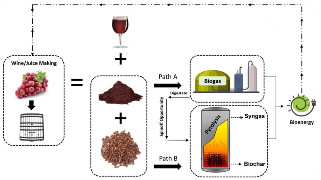
Plasma Arc Gasification (PAG) is an advanced waste-to-energy technology that converts municipal solid waste, industrial waste, biomass, or hazardous materials into syngas and vitrified slag using extremely high temperatures generated by plasma arcs. Unlike conventional incineration, plasma gasification operates in an oxygen-starved environment, preventing direct combustion and enabling the chemical breakdown of complex materials into simple gaseous molecules and inert solids. This process offers a sustainable approach for energy recovery, waste volume reduction, and the management of hazardous or difficult-to-treat waste streams.
Key features of Plasma Arc Gasification:
- High-temperature processing: Plasma arcs can reach temperatures of 3,000–10,000°C, sufficient to break down organic matter into syngas composed primarily of hydrogen (H₂) and carbon monoxide (CO). Inorganic components are melted into a vitrified, non-leachable slag.
- Feedstock flexibility: PAG can process a wide range of wastes, including municipal solid waste, industrial residues, electronic waste, medical waste, biomass, and contaminated materials that are unsuitable for conventional incineration.
- Minimal emissions: Operating in a low-oxygen environment significantly reduces the formation of nitrogen oxides (NOx), dioxins, and furans. Syngas can be cleaned and used for electricity generation or chemical synthesis, while slag is inert and environmentally safe.
Main parts of a Plasma Arc Gasification Plant:
- Waste Reception and Preprocessing: Waste is delivered, weighed, and sorted to remove non-gasifiable contaminants. Preprocessing may include shredding, drying, or homogenization to ensure uniform feedstock for the gasification chamber.
- Feedstock Feeding System: Preprocessed waste is continuously or intermittently fed into the plasma gasification reactor using conveyors, hoppers, or feeders designed to maintain controlled throughput and prevent air ingress.
- Plasma Gasification Reactor: The core unit where waste is subjected to intense plasma arcs. Organic matter is converted into syngas, while inorganic components form molten slag. The reactor is heavily insulated and equipped with temperature and pressure sensors to maintain optimal conditions.
- Syngas Cooling and Cleaning Systems: Produced syngas is extremely hot and contains particulates, tars, and contaminants. Cooling systems such as heat exchangers reduce gas temperature, while scrubbers, filters, and chemical treatments remove particulates, sulfur compounds, and other impurities. Clean syngas can then be used for combustion, turbines, engines, or chemical synthesis.
- Energy Conversion Units: Clean syngas is combusted in gas engines, turbines, or boilers to produce electricity and heat. Some plants integrate combined heat and power (CHP) systems to maximize energy recovery.
- Slag Handling System: Inorganic residues from the reactor solidify into a vitrified slag that is non-leachable, environmentally safe, and can be used in construction materials, road aggregates, or safely landfilled. Slag is collected, cooled, and conveyed for further use or disposal.
- Control and Monitoring Systems: Advanced automation ensures safe operation, optimized reactor performance, syngas quality, and emissions compliance. Sensors monitor temperature, pressure, feedstock flow, gas composition, and slag formation, while emergency shutdown and safety systems protect personnel and equipment.
Advantages of Plasma Arc Gasification:
- High energy efficiency and recovery of electricity and heat from a variety of wastes.
- Significant reduction in waste volume and stabilization of hazardous materials.
- Production of clean syngas and inert slag with minimal environmental impact.
- Flexibility to process mixed, contaminated, or low-calorific-value feedstocks.
In summary, Plasma Arc Gasification is an advanced thermal treatment technology that converts organic and inorganic waste into high-value syngas and inert slag using extreme temperatures and oxygen-limited conditions. With integrated preprocessing, plasma reactors, gas cleaning, energy conversion, and slag handling systems, PAG plants provide efficient, environmentally responsible, and highly flexible waste-to-energy solutions.
Waste Reception and Preprocessing
The Waste Reception and Preprocessing stage in a Plasma Arc Gasification (PAG) Plant is the first critical step in ensuring that incoming waste is suitable for high-temperature gasification, while protecting equipment and maintaining process efficiency. Proper handling and conditioning of waste are essential for stable reactor operation, consistent syngas production, and minimal operational disruptions.
Waste reception typically includes tipping floors, unloading docks, or storage bunkers where municipal, industrial, or hazardous waste is delivered. Incoming materials are weighed, classified, and inspected to identify non-gasifiable contaminants such as metals, glass, stones, or oversized objects. Hazardous materials that cannot be processed safely are segregated for specialized treatment or disposal.
Preprocessing operations prepare waste for uniform feeding and efficient gasification:
- Shredding or grinding: Reduces particle size to increase surface area, ensuring more complete and consistent conversion into syngas.
- Drying or moisture adjustment: Excessive moisture can reduce reactor temperature and efficiency. Preprocessing may include drying to achieve optimal moisture content for plasma gasification.
- Homogenization or mixing: Waste with variable composition is blended to create a uniform feedstock, preventing uneven gasification or localized temperature fluctuations.
- Contaminant removal: Mechanical screens, magnetic separators, or eddy current separators extract metals, stones, or non-combustible materials that could damage reactors or interfere with slag formation.
Safety and environmental considerations are integrated into this stage. Enclosures, dust collection systems, and negative-pressure ventilation reduce airborne particulates and odors. Operators are protected from hazardous materials through automated handling, remote monitoring, and interlocks.
Monitoring and control enhance efficiency and reliability. Sensors track waste composition, particle size, moisture content, and storage levels. Data is fed into the plant control system to optimize preprocessing and feeding schedules, ensuring consistent reactor performance.
In summary, Waste Reception and Preprocessing in a Plasma Arc Gasification Plant ensures that incoming waste is properly inspected, conditioned, and prepared for efficient and safe high-temperature gasification. By integrating shredding, drying, homogenization, contaminant removal, and automated monitoring, this stage supports stable reactor operation, consistent syngas production, and environmentally responsible plant operation.
Feedstock Feeding System
The Feedstock Feeding System in a Plasma Arc Gasification (PAG) Plant is responsible for delivering preprocessed waste into the plasma gasification reactor at a controlled and consistent rate. Proper feeding is critical to maintain reactor stability, ensure uniform gasification, and maximize the production of high-quality syngas while protecting the reactor from operational disturbances.
Feeding mechanisms are designed according to waste type, moisture content, and reactor configuration:
- Conveyor-based systems: Screw conveyors, belt conveyors, or ram feeders are commonly used to transport solid or shredded waste into the reactor. These systems provide precise control over feed rates and prevent blockages.
- Hydraulic or pneumatic feeding: For semi-solid or slurry-like wastes, hydraulic rams or pneumatic transport systems can deliver material into pressurized reactors.
- Batch vs. continuous feeding: Some plasma gasifiers operate in a batch mode, where measured quantities of waste are fed at intervals, while most modern systems use continuous feeding to maintain steady-state reactor conditions and consistent syngas production.
Control and monitoring are integral to the feeding system. Sensors track feed rate, waste composition, moisture content, and conveyor operation. Data is relayed to the plant’s control system, which adjusts feeding speed, hopper levels, and flow mechanisms to maintain consistent reactor loading and avoid over- or under-feeding, which could destabilize the plasma arc and reduce energy efficiency.
Safety and environmental considerations include:
- Enclosed feeding systems with dust extraction to minimize airborne particulates and odors.
- Interlocks and emergency shutdown mechanisms to prevent overfeeding or blockages that could damage the reactor.
- Monitoring of waste characteristics to avoid introducing hazardous contaminants that may compromise reactor integrity or syngas quality.
In summary, the Feedstock Feeding System in a Plasma Arc Gasification Plant ensures the safe, controlled, and continuous delivery of preprocessed waste into the reactor. By integrating precise mechanical or hydraulic feeding, automated monitoring, and safety measures, this system supports stable plasma operation, efficient syngas production, and reliable overall plant performance.
Plasma Gasification Reactor
The Plasma Gasification Reactor is the core unit of a Plasma Arc Gasification (PAG) Plant, where preprocessed waste is thermochemically converted into syngas and vitrified slag under extremely high temperatures in an oxygen-starved environment. The reactor is designed to withstand intense heat and corrosive conditions while ensuring efficient gasification of organic materials and safe handling of inorganic residues.
Key features and design aspects:
- High-temperature plasma arcs: Plasma torches generate temperatures ranging from 3,000°C to 10,000°C, sufficient to break down complex organic molecules into simple gases such as hydrogen (H₂) and carbon monoxide (CO), while melting inorganic components into an inert, glass-like slag.
- Oxygen-limited environment: By restricting oxygen, the reactor prevents direct combustion, allowing controlled chemical decomposition of waste into syngas rather than ash. This reduces emissions of nitrogen oxides (NOx), dioxins, and furans.
- Refractory lining and insulation: The reactor is heavily insulated with high-temperature refractory materials to protect the structure, contain heat, and maintain energy efficiency. Cooling systems may also be integrated to protect plasma torches and reactor walls.
- Continuous or batch operation: Most modern plasma reactors operate continuously, with steady feedstock input and continuous slag removal. Some smaller or specialized reactors operate in batch mode.
Syngas production: Organic components of the waste are broken down into a hydrogen- and carbon monoxide-rich gas mixture. The syngas is extremely hot, requiring immediate cooling and cleaning to prevent equipment damage downstream.
Slag formation: Inorganic materials such as metals, glass, and minerals melt in the high-temperature environment and solidify into vitrified slag, which is chemically inert, non-leachable, and environmentally safe. The molten slag is periodically removed via bottom discharge systems or cooled and transported for reuse in construction or safe disposal.
Monitoring and control: The reactor is equipped with advanced sensors for temperature, pressure, plasma arc stability, feedstock input, and syngas composition. These parameters are continuously monitored and controlled through an integrated plant control system to maintain optimal gasification conditions and ensure consistent energy output.
Safety measures: The reactor includes multiple safety systems, including:
- Emergency shutdowns for plasma torches or feed systems.
- Pressure relief valves to prevent overpressure events.
- Gas detection and ventilation systems to manage accidental leaks of combustible syngas.
In summary, the Plasma Gasification Reactor is the heart of a PAG plant, converting preprocessed waste into high-quality syngas and inert slag through extreme-temperature, oxygen-limited processing. By combining advanced thermal design, refractory protection, precise feedstock management, and integrated monitoring, the reactor ensures efficient, safe, and environmentally responsible waste-to-energy conversion.
Syngas Cooling and Cleaning Systems
The Syngas Cooling and Cleaning Systems in a Plasma Arc Gasification (PAG) Plant are essential downstream units that condition and purify the raw syngas produced in the reactor, ensuring it is suitable for energy conversion, chemical synthesis, or other applications. Raw syngas generated in plasma reactors is extremely hot, contains particulates, tars, and contaminants such as sulfur compounds, chlorine, and heavy metals. Proper cooling and cleaning protect downstream equipment, improve energy efficiency, and ensure compliance with environmental standards.
Syngas cooling:
- Raw syngas exits the reactor at temperatures often exceeding 1,000°C. High temperatures must be reduced to prevent damage to engines, turbines, or gas cleaning equipment.
- Cooling is achieved using quench systems, heat exchangers, or direct contact with water/steam, which rapidly lower the temperature while recovering thermal energy. Some systems integrate heat recovery to preheat feedwater, generate steam, or supply process heat.
Particulate and tar removal:
- Syngas carries fine particulates and condensed tars that can damage engines or turbines.
- Mechanical separation methods, such as cyclones, bag filters, or electrostatic precipitators, remove solids efficiently.
- Tar removal is achieved through condensation, scrubbing, or catalytic cracking systems to prevent fouling and maintain syngas quality.
Gas contaminant removal:
- Sulfur compounds (H₂S), halogens, ammonia, and trace metals are removed using chemical scrubbers, activated carbon filters, or wet/dry gas cleaning systems.
- Removal of these contaminants prevents corrosion, reduces emissions, and ensures the syngas meets the specifications required for energy conversion or chemical synthesis.
Monitoring and control:
- Continuous sensors measure temperature, pressure, particulate load, gas composition, and contaminant levels.
- Automated control systems adjust cooling rates, scrubber flow, filter cleaning cycles, and other parameters to maintain consistent syngas quality and protect downstream equipment.
Safety considerations:
- Syngas is highly combustible. Enclosed systems, pressure relief valves, flame arrestors, and gas leak detection prevent accidents.
- Ventilation and emergency shutdown systems ensure safe handling during maintenance or abnormal operating conditions.
In summary, the Syngas Cooling and Cleaning Systems in a Plasma Arc Gasification Plant transform extremely hot, contaminated raw syngas into a stable, clean, and usable fuel. By combining thermal management, particulate and tar removal, contaminant scrubbing, and integrated monitoring, these systems protect equipment, optimize energy conversion, and ensure environmentally responsible operation.
Energy Conversion Units
The Energy Conversion Units in a Plasma Arc Gasification (PAG) Plant are responsible for transforming cleaned syngas into usable energy, typically in the form of electricity, heat, or combined heat and power (CHP). Proper design and integration of these units are crucial to maximize energy recovery, maintain plant efficiency, and ensure environmentally responsible operation.
Key methods of energy conversion include:
- Gas Engines (Reciprocating Internal Combustion Engines):
- Suitable for small to medium-scale plants.
- Convert methane- and carbon monoxide-rich syngas into electricity and usable heat.
- Often coupled with CHP systems to recover waste heat for process heating or district heating.
- Gas Turbines:
- Suitable for larger-scale plants or high-quality syngas streams.
- Convert syngas into electricity efficiently.
- Can be integrated with heat recovery steam generators (HRSG) to utilize waste heat for industrial processes or digester heating.
- Boilers:
- Burn syngas to produce thermal energy, which can be used for industrial applications, district heating, or preheating plasma torches.
- Particularly useful when heat demand exceeds electricity demand.
- Combined Heat and Power (CHP) Systems:
- Integrate electricity generation with heat recovery, maximizing overall energy efficiency.
- Waste heat can be redirected to maintain plasma arc temperatures, supply industrial processes, or provide local heating solutions.
Control and monitoring:
- Sensors track syngas flow, composition, temperature, pressure, and energy output.
- Automated controls optimize fuel input, combustion efficiency, and heat recovery, ensuring stable operation and protecting equipment from damage due to fluctuations in syngas quality.
Safety measures:
- Flame arrestors, gas leak detectors, and emergency shutdown systems prevent accidents from combustible syngas.
- Ventilation and containment systems manage residual gases and protect personnel.
Maintenance and reliability:
- Predictive monitoring of engines, turbines, and boilers allows proactive maintenance, reducing downtime and operational costs.
- Proper syngas cleaning upstream is essential to prevent fouling, corrosion, or damage to energy conversion units.
In summary, the Energy Conversion Units in a Plasma Arc Gasification Plant efficiently transform cleaned syngas into electricity, heat, or CHP, optimizing energy recovery and overall plant performance. Integrated monitoring, control systems, and safety mechanisms ensure reliable, efficient, and environmentally responsible energy utilization.
Control and Monitoring Systems
The Control and Monitoring Systems in a Plasma Arc Gasification (PAG) Plant provide the centralized management framework that ensures safe, efficient, and reliable operation of all plant processes, from feedstock handling and reactor operation to syngas cleaning, energy conversion, and slag handling. Given the high temperatures, complex chemical reactions, and hazardous gases involved, advanced control systems are essential to optimize performance, maintain safety, and comply with environmental regulations.
Core functions include:
- Process Monitoring:
- Sensors track critical parameters such as feedstock flow, plasma arc temperature, reactor pressure, syngas composition (H₂, CO, CH₄), particulate load, slag formation, and energy output.
- Continuous monitoring ensures that operational parameters remain within safe and efficient ranges, allowing early detection of anomalies.
- Automation and Process Control:
- Integrated control systems regulate plasma torch power, feedstock feeding rates, reactor temperature, cooling water flow, syngas cleaning operations, and energy conversion unit performance.
- Automation maintains steady-state reactor operation, maximizes syngas quality, and optimizes electricity or heat generation.
- Safety Management:
- Gas leak detectors, flame arrestors, overpressure relief valves, and emergency shutdown systems prevent accidents from combustible syngas and high-temperature reactor conditions.
- Fire detection and suppression systems, ventilation controls, and interlocks ensure personnel and equipment safety.
- Environmental Compliance:
- Continuous emission monitoring tracks pollutants such as particulates, sulfur compounds, halogens, and trace metals.
- Automated adjustments to gas cleaning and treatment systems help maintain compliance with regulatory standards.
- Data Logging and Predictive Maintenance:
- Historical operational data is collected to support trend analysis, regulatory reporting, and predictive maintenance.
- By analyzing performance trends in plasma torches, reactors, and energy conversion units, maintenance can be scheduled proactively, minimizing unplanned downtime.
- User Interface and Visualization:
- SCADA or DCS platforms provide operators with real-time dashboards, alarms, trend analysis, and reports.
- These interfaces allow quick decision-making, efficient plant management, and coordination between multiple plant systems.
In summary, Control and Monitoring Systems in a Plasma Arc Gasification Plant are the backbone of operational efficiency, safety, and regulatory compliance. By integrating real-time monitoring, automation, safety systems, and data analytics, these systems ensure stable reactor operation, optimized syngas production, reliable energy conversion, safe slag handling, and environmentally responsible plant operation.
EMS Power Machines
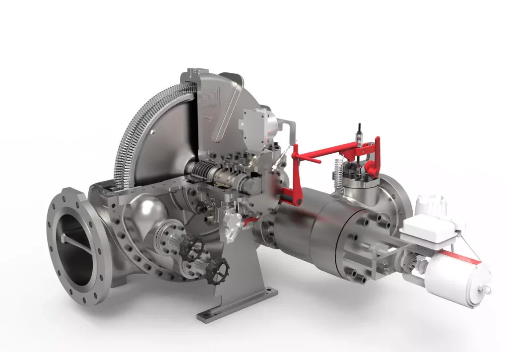
We design, manufacture and assembly Power Machines such as – diesel generators, electric motors, vibration motors, pumps, steam engines and steam turbines
EMS Power Machines is a global power engineering company, one of the five world leaders in the industry in terms of installed equipment. The companies included in the company have been operating in the energy market for more than 60 years.
EMS Power Machines manufactures steam turbines, gas turbines, hydroelectric turbines, generators, and other power equipment for thermal, nuclear, and hydroelectric power plants, as well as for various industries, transport, and marine energy.
EMS Power Machines is a major player in the global power industry, and its equipment is used in power plants all over the world. The company has a strong track record of innovation, and it is constantly developing new and improved technologies.
Here are some examples of Power Machines’ products and services:
- Steam turbines for thermal and nuclear power plants
- Gas turbines for combined cycle power plants and industrial applications
- Hydroelectric turbines for hydroelectric power plants
- Generators for all types of power plants
- Boilers for thermal power plants
- Condensers for thermal power plants
- Reheaters for thermal power plants
- Air preheaters for thermal power plants
- Feedwater pumps for thermal power plants
- Control systems for power plants
- Maintenance and repair services for power plants
EMS Power Machines is committed to providing its customers with high-quality products and services. The company has a strong reputation for reliability and innovation. Power Machines is a leading provider of power equipment and services, and it plays a vital role in the global power industry.
EMS Power Machines, which began in 1961 as a small factory of electric motors, has become a leading global supplier of electronic products for different segments. The search for excellence has resulted in the diversification of the business, adding to the electric motors products which provide from power generation to more efficient means of use.