Generating Electricity using Heat from Food and Beverage Pasteurization: Generating electricity from steam involves a process called thermodynamic power generation, often using steam turbines as the primary mechanism. This process converts the energy in steam, usually created by boiling water using heat from burning fuel, nuclear reactions, or geothermal energy, into mechanical energy, which is then transformed into electrical energy.
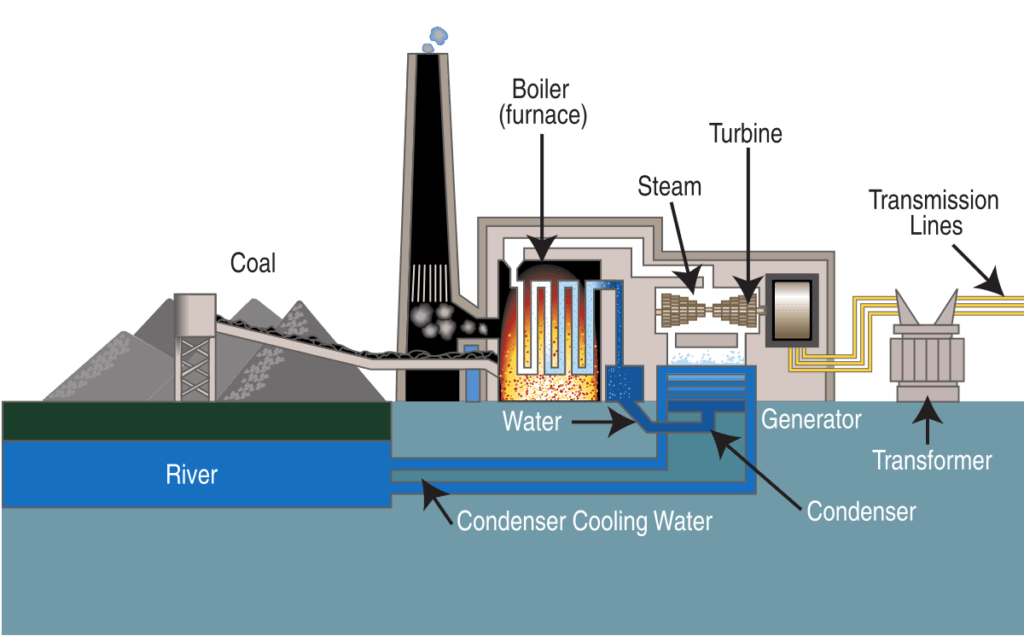
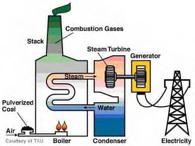
The basic steps to generate electricity from steam start with the heating of water to produce steam. This can be done in a boiler or a heat exchanger, depending on the system’s design. In a boiler, fuel such as coal, natural gas, oil, or even biomass is burned to generate heat. In a nuclear power plant, heat is produced from nuclear fission reactions. Alternatively, in geothermal power plants, heat from the Earth’s natural reservoirs is used to convert water into steam.
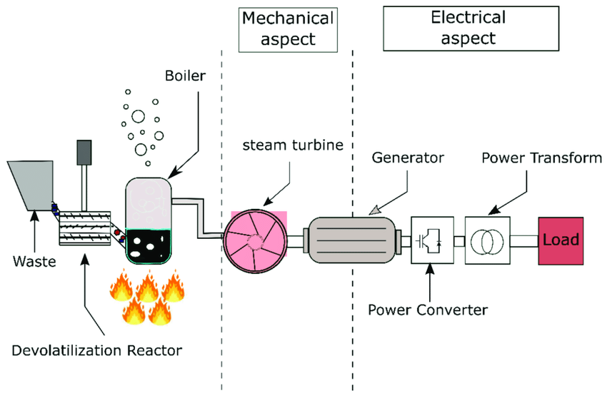
Once steam is produced, it is directed into a steam turbine. The turbine consists of blades mounted on a shaft. As steam flows over the blades, the force of the steam causes the blades to spin. This mechanical energy of the rotating turbine blades is then transferred to a generator connected to the turbine. The generator uses the mechanical energy to rotate a magnetic field within a set of coils, inducing an electrical current through electromagnetic induction.
The steam turbine operates based on the principles of thermodynamics, particularly the Rankine cycle. In the Rankine cycle, steam is generated at high pressure and temperature, expanded in the turbine, and then condensed back into water in a condenser. This process of expansion and condensation allows for a continuous cycle of energy conversion. The condenser cools the steam, usually by passing it through cooling towers or heat exchangers, and converts it back into liquid water, which is then pumped back into the boiler to be reheated and turned back into steam.
In larger power plants, multiple stages of turbines are often used to maximize efficiency. This is known as a multi-stage turbine system, where steam passes through several turbines at different pressure levels. The steam’s pressure is gradually reduced as it moves through each turbine, extracting more energy. In many systems, the steam is also reheated between stages to maintain its energy content and prevent too much pressure drop in the turbines.
The efficiency of a steam power plant is largely determined by how well it can maintain the pressure and temperature of the steam as it moves through the system, as well as the efficiency of the turbine and the generator. Steam turbines are capable of converting a large percentage of the heat energy into mechanical work, but some energy is always lost in the process, primarily due to heat dissipation in the condenser and the inevitable frictional losses in the turbine and other moving parts.
To improve the efficiency of electricity generation, some plants incorporate regenerative systems, where part of the steam or exhaust gases are used to preheat incoming water before it enters the boiler. This reduces the amount of fuel needed to heat the water to the required steam temperature, leading to a more energy-efficient process.
Once the electrical energy is generated, it is transmitted through power lines and distributed to homes and businesses. The voltage of the generated electricity is stepped up by a transformer for long-distance transmission, reducing energy loss during transport. At the point of use, the voltage is stepped down again to a level suitable for household or industrial applications.
In addition to conventional coal, oil, and natural gas power plants, steam turbines are also widely used in renewable energy sources. Geothermal power plants use naturally occurring steam from deep within the Earth to generate electricity, while solar thermal plants use mirrors or lenses to concentrate sunlight and heat a fluid that produces steam. These renewable methods of generating steam offer a more sustainable way to generate electricity without burning fossil fuels.
Overall, generating electricity from steam is a well-established and versatile technology that continues to be used in power plants around the world, with ongoing research focused on improving its efficiency, reducing emissions, and expanding its use in renewable energy systems.
In the process of steam-based electricity generation, one of the key elements that influence performance is the design and operation of the steam turbine itself. The turbine is designed to convert the thermal energy from steam into mechanical energy efficiently. This is achieved by careful engineering of the turbine blades, which are shaped to extract the maximum amount of energy from the steam as it flows over them. The steam enters the turbine under high pressure and high temperature, and as it expands and loses pressure, it passes through different stages of turbines with progressively smaller blades. These stages allow for a more gradual and efficient transfer of energy.
After passing through the turbines, the steam exits at lower pressure and temperature. To complete the cycle, the steam must be condensed back into water in a process that typically occurs in a condenser. The condenser cools the steam, causing it to lose its heat and turn back into liquid form. In most systems, water from nearby rivers, lakes, or cooling towers is used to absorb the excess heat from the steam, often at a temperature below 40°C to 50°C, depending on the local climate and environmental regulations.
The condensed water, now in liquid form, is collected and pumped back into the boiler to be reheated and transformed into steam once again. This closed-loop system helps to conserve water and reduce environmental impacts, though some plants may use once-through cooling systems where water is used only once before being returned to its source.
As part of the overall power plant system, the generator that is coupled to the turbine plays a critical role in converting the mechanical energy into electrical energy. The generator consists of a rotating shaft and a set of stationary coils or magnets. As the turbine shaft rotates, it turns the generator’s rotor, creating a changing magnetic field within the coils, which induces an electrical current through the wires by the principle of electromagnetic induction. This electrical current is then transferred through transformers, where its voltage is adjusted to be suitable for transmission over long distances. Once the electricity reaches its destination, transformers step down the voltage again for distribution to households or businesses.
A significant part of the energy generated by the steam turbine system is often lost as heat due to the second law of thermodynamics, which states that some energy is always lost to the surroundings. Efficiency improvements, such as the integration of combined-cycle power plants, aim to capture and utilize some of this waste heat. In combined-cycle systems, the exhaust gases from the gas turbine are used to heat water, which then produces additional steam to drive a steam turbine. This significantly increases the overall efficiency of the plant, sometimes by as much as 50% or more compared to a simple steam turbine system.
Another emerging trend in steam-based electricity generation is the implementation of supercritical and ultra-supercritical steam cycles. These systems use steam at higher pressures and temperatures than conventional methods, resulting in higher thermodynamic efficiency and lower emissions. By using steam at supercritical pressures (above 22.1 MPa) and ultra-supercritical pressures (above 30 MPa), the thermal efficiency of power plants can be greatly improved, allowing them to generate more electricity from the same amount of fuel. These advanced steam turbines are typically found in modern coal-fired power plants, as well as some nuclear and combined-cycle plants.
Environmental concerns have led to the development of cleaner technologies for generating electricity from steam. The burning of fossil fuels in traditional steam plants releases carbon dioxide (CO₂) and other greenhouse gases into the atmosphere, contributing to climate change. To mitigate these effects, power plants have started implementing carbon capture and storage (CCS) technologies, which capture CO₂ emissions from the exhaust gases and store them underground or use them in industrial processes. Additionally, the growing adoption of renewable energy sources such as geothermal, solar thermal, and biomass for generating steam offers a way to produce electricity with fewer environmental impacts.
While fossil fuels continue to dominate global electricity generation from steam, the trend toward cleaner energy solutions is growing. Geothermal plants, for example, utilize steam sourced from the Earth’s natural heat, which is renewable and produces no direct emissions. Solar thermal power plants use mirrors or lenses to concentrate sunlight, heating a fluid that can generate steam. In some regions, biomass and waste-to-energy plants are being developed to convert organic materials into steam, contributing to reducing waste while generating power.
In summary, the generation of electricity from steam is a well-established and essential method of power generation, with significant advancements in turbine technology, heat recovery systems, and renewable energy integration. The efficiency of the process has been continuously improved over the years, and innovations such as combined-cycle plants and ultra-supercritical steam systems are pushing the boundaries of what is possible. As global energy demands rise and environmental concerns increase, the role of steam-based power generation in providing a reliable and cleaner energy supply will continue to evolve.
How to Generate Electricity from Steam?
As the world moves towards more sustainable energy practices, the role of steam-based electricity generation remains pivotal, albeit with shifts in how it is implemented and integrated with renewable energy sources. Traditional steam-based systems, which rely heavily on burning fossil fuels such as coal, natural gas, or oil, face increasing scrutiny due to their environmental impact, particularly in terms of carbon emissions. As a result, there has been a substantial push to modernize steam power plants, incorporating new technologies and improving the overall energy efficiency of the process.
One of the primary areas of focus in advancing steam-based electricity generation is the development and implementation of carbon capture, utilization, and storage (CCUS) technologies. These systems capture CO₂ emissions produced during the combustion of fossil fuels, preventing them from entering the atmosphere and contributing to climate change. In some systems, the captured CO₂ can be used in industrial processes, such as enhancing oil recovery or producing synthetic fuels, making the technology potentially economically viable in certain contexts. CCUS is seen as a critical part of reducing emissions from traditional fossil-fuel-based power plants, including steam turbines, and is a focal point of research for improving the environmental footprint of steam-based electricity generation.
Moreover, the energy transition is driving a renewed interest in hybrid systems that combine steam-based power generation with renewable energy sources. One notable example is the integration of solar thermal energy into steam power plants. Solar thermal plants use mirrors or lenses to concentrate sunlight and heat a working fluid, often oil or molten salt, which can then be used to produce steam. This process mirrors traditional steam generation, but the heat source is clean and renewable. In some cases, solar thermal plants are combined with conventional steam turbines in hybrid systems, where the steam turbine can operate using both solar heat and the backup from fossil fuels or other energy sources when sunlight is insufficient.
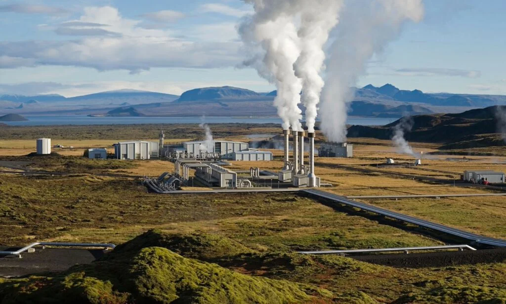
Geothermal energy, another renewable energy source, has long been a significant contributor to steam-based power generation. In geothermal power plants, steam is extracted from the Earth’s natural geothermal reservoirs and used to turn turbines. Geothermal plants operate efficiently in regions with significant geothermal activity, such as Iceland, parts of the United States (e.g., California), and the Philippines. These plants offer the advantage of being able to provide a constant, baseload supply of electricity, since the Earth’s heat is inexhaustible on human timescales. Unlike solar and wind power, which can be intermittent, geothermal energy is available 24/7, making it a reliable renewable energy source.
In addition to integrating renewable sources, there has been a push to utilize advanced materials and design innovations to increase the efficiency of steam turbines and reduce energy losses. High-efficiency materials are being developed to withstand the extreme pressures and temperatures encountered in modern steam turbines, allowing for more efficient power generation. For example, advanced alloys and coatings can improve the turbine’s resistance to corrosion and thermal degradation, extending the lifespan of the turbine and maintaining high levels of efficiency throughout its operation.
The ongoing trend toward supercritical and ultra-supercritical steam cycles is also helping to push the boundaries of steam-based power generation efficiency. By operating at pressures and temperatures beyond the traditional limits of the steam cycle, these advanced turbines extract more energy from the same amount of fuel. Supercritical plants are typically used in newer coal-fired power plants and some nuclear plants, allowing them to operate more efficiently while reducing emissions. However, the high cost of building and maintaining these advanced systems remains a challenge, which is why their adoption has been somewhat limited in many regions.
A promising area of development is the application of advanced digital technologies to monitor and optimize steam turbine performance. Through the use of sensors, data analytics, and artificial intelligence (AI), power plant operators can gain real-time insights into turbine performance, detect inefficiencies or anomalies, and adjust operational parameters to optimize efficiency and reduce downtime. Predictive maintenance tools are also being used to forecast when components of the turbine or other systems might fail, allowing for proactive maintenance to prevent costly failures and extend the operational life of the plant.
Alongside these technological advancements, there is growing interest in decentralized power generation models that use smaller, modular steam systems to provide local or regional electricity. Microgrids, which can be powered by small-scale steam turbines or other distributed energy sources, offer the potential for localized generation with lower transmission losses and enhanced grid resilience. For example, biomass plants, which use organic materials such as wood pellets or agricultural waste to generate steam, can be deployed in rural or remote areas to provide power. These systems are particularly attractive in regions with abundant biomass resources, where the steam can be produced locally and used to provide electricity with a minimal carbon footprint.
The global energy transition is also influencing the development of new energy systems that combine steam turbines with energy storage technologies. For example, some power plants are integrating steam turbines with large-scale battery storage systems or pumped hydro storage, which can store excess energy produced during periods of high demand or when renewable sources like solar and wind are producing more electricity than is needed. This stored energy can then be used to produce steam when demand is high or when renewable energy generation is low, providing grid stability and ensuring a constant supply of power.
In the future, steam turbines may also play a role in the hydrogen economy. Hydrogen, particularly green hydrogen produced through electrolysis powered by renewable electricity, is gaining attention as a potential clean energy source. Steam turbines could be used in combined systems that generate hydrogen through high-temperature electrolysis or other processes, and then use the hydrogen to generate power or heat in various applications. Additionally, steam turbines might be used in plants that convert hydrogen into electricity, acting as an efficient and flexible component in a hydrogen-powered energy system.
As the world continues to seek solutions to the challenges of climate change and energy security, steam-based electricity generation remains a cornerstone of the global energy mix. By evolving alongside advances in technology, renewable energy integration, and emission reduction strategies, the steam turbine continues to serve as a vital tool in the transition to a cleaner, more sustainable energy future.
Generating Electricity using waste heat from rotary kilns
Generating electricity using waste heat from rotary kilns is an innovative approach that aims to capture the excess thermal energy generated during industrial processes, typically in cement, lime, and other heavy industries, and convert it into electrical energy. Rotary kilns, which are large, cylindrical furnaces used for high-temperature processes such as calcination (in cement production), smelting, or chemical manufacturing, are notorious for producing a significant amount of waste heat. This waste heat can be harnessed through various methods to produce electricity, providing an energy-efficient solution and reducing the overall environmental impact of industrial operations.
Waste Heat Recovery Process
The process of generating electricity from waste heat in rotary kilns typically involves several key steps:
- Heat Recovery System (HRS): The first step is to capture the heat from the rotary kiln. This is often achieved through the installation of heat recovery systems, such as waste heat boilers or heat exchangers. The hot gases that exit the kiln, typically at temperatures of 300–400°C (or higher), pass through these systems, where the heat is transferred to a working fluid, usually water or air.
- Heat Transfer to Fluid: In many systems, waste heat is transferred to water in a waste heat boiler. The water absorbs the heat, turning it into steam. In other systems, air can be heated directly in heat exchangers and sent to other parts of the plant for use in various processes or in a thermal energy storage system.
- Steam Generation: When water is used, the waste heat from the rotary kiln boils the water, creating steam. This steam is then fed into a steam turbine generator system. The high-pressure steam drives the turbine, converting thermal energy into mechanical energy.
- Power Generation via Steam Turbine: The steam turbine is connected to a generator, and as the turbine spins, it drives the generator to produce electricity. The mechanical energy of the rotating turbine is converted into electrical energy via electromagnetic induction in the generator. The process is similar to traditional steam-based power generation but utilizes waste heat as the energy source instead of burning additional fuel.
- Condensation and Recirculation: After the steam passes through the turbine, it is condensed back into water in a condenser. The condensed water is then pumped back into the waste heat recovery system to be reheated, and the cycle continues, creating a closed-loop system.
- Supplementary Use of Exhaust Gases: In some cases, excess exhaust gases can be used for additional heat recovery. Instead of allowing these gases to escape into the atmosphere, they can be directed through secondary heat exchangers to further preheat incoming combustion air or to generate additional power, improving the overall energy efficiency of the system.
Efficiency Considerations
The efficiency of generating electricity using waste heat from rotary kilns depends on several factors, including the temperature of the exhaust gases, the design of the heat recovery system, and the efficiency of the steam turbine and generator. Generally, the higher the temperature of the waste gases, the more effective the heat recovery process will be, as it allows for greater amounts of thermal energy to be captured and converted into electricity.
The efficiency of waste heat recovery is also influenced by the system’s design. For example, in some modern systems, the waste heat boiler is designed to maximize the transfer of heat from the exhaust gases to the water, increasing the overall efficiency. Additionally, using multi-stage turbines or combining different waste heat recovery systems, such as using hot air and water-based heat exchangers, can help improve energy recovery.
Furthermore, the effectiveness of the steam turbine plays a significant role in the overall efficiency. Advanced turbines designed to operate at higher pressures and temperatures can extract more energy from the steam, increasing the amount of electricity generated. Similarly, the generator’s efficiency in converting mechanical energy into electrical energy affects the overall performance of the system.
Types of Systems for Generating Electricity from Waste Heat
There are several different systems designed to recover and convert waste heat from rotary kilns into electricity, each with its own advantages and applications:
- Rankine Cycle System (Steam Cycle): The Rankine cycle is the most common method for generating electricity from waste heat in rotary kilns. This system uses the waste heat to produce steam, which drives a steam turbine connected to a generator. The Rankine cycle is widely used in industries where a significant amount of waste heat is generated at relatively high temperatures.
- Organic Rankine Cycle (ORC) System: The Organic Rankine Cycle (ORC) is a variation of the traditional Rankine cycle that uses an organic fluid, such as refrigerants, instead of water to drive the turbine. The organic fluid has a lower boiling point than water, which allows it to be used for lower-temperature waste heat recovery (typically in the range of 100–300°C). This makes ORC systems particularly well-suited for applications where the waste heat from rotary kilns is not high enough to generate steam in a traditional Rankine cycle.
- Thermoelectric Generators (TEGs): Another emerging technology for generating electricity from waste heat is the use of thermoelectric generators (TEGs). These devices work based on the Seebeck effect, where a temperature difference across two different materials creates an electrical voltage. While TEGs have lower efficiencies compared to steam turbine-based systems, they are compact and can be used in specific applications where small-scale electricity generation is needed.
- Kalina Cycle: The Kalina cycle is an advanced thermodynamic cycle that uses a mixture of water and ammonia as the working fluid. The advantage of the Kalina cycle is that it can achieve higher thermal efficiency than the traditional Rankine cycle, especially when dealing with waste heat at moderate temperatures. The Kalina cycle can be used in applications where the temperature of the waste heat is not high enough for conventional steam turbines to operate efficiently.
- Gas Turbine Systems: For rotary kilns that produce waste heat in the form of hot gases, a gas turbine can be used to generate electricity. In this system, the exhaust gases from the kiln are passed through the gas turbine, which converts the thermal energy into mechanical energy. The rotating turbine then drives a generator to produce electricity. While this system is more commonly used in industries that burn natural gas, it can also be applied to rotary kilns with high-temperature exhaust gases.
Benefits of Waste Heat Recovery for Power Generation
- Energy Efficiency: Capturing and using waste heat from rotary kilns improves the overall energy efficiency of the industrial process. By converting waste heat into electricity, industries can reduce their reliance on external power sources, leading to cost savings and a smaller carbon footprint.
- Reduced Environmental Impact: Using waste heat reduces the amount of energy that must be generated from conventional sources, such as fossil fuels, which in turn lowers greenhouse gas emissions. It also helps to reduce the need for cooling systems that consume additional energy.
- Cost Savings: By harnessing waste heat for power generation, industrial facilities can reduce their energy costs. The electricity generated can be used internally to power equipment or sold back to the grid, providing a potential source of revenue.
- Sustainability: Waste heat recovery contributes to the sustainability goals of industries by promoting the use of renewable energy (in the form of recovered waste heat) and reducing the overall consumption of fossil fuels.
Challenges
While the potential benefits of generating electricity from waste heat are significant, there are also some challenges. The initial capital cost of installing waste heat recovery systems can be high, and the return on investment may take several years to materialize. Furthermore, the system’s efficiency depends heavily on the temperature and volume of waste heat available, which can vary depending on the type of rotary kiln and the process conditions. Finally, the integration of these systems into existing industrial operations can be complex, requiring careful planning and potentially significant modifications to the plant’s infrastructure.
In conclusion, generating electricity from waste heat in rotary kilns offers a promising method to improve energy efficiency, reduce costs, and decrease the environmental impact of industrial processes. By capturing the waste heat produced during high-temperature operations and converting it into electrical energy, industries can make more sustainable use of the resources at their disposal, while contributing to a greener, more energy-efficient industrial landscape.
As industries continue to look for ways to improve energy efficiency and reduce environmental impacts, the integration of waste heat recovery systems for power generation in rotary kilns becomes an increasingly attractive solution. This process not only helps businesses lower operational costs but also supports the broader goals of sustainability and reducing carbon emissions. As we explore further, it’s important to dive deeper into the challenges, innovations, and potential applications of these systems.
Advanced Technological Innovations in Waste Heat Recovery
The ongoing development of waste heat recovery systems is focused on improving both efficiency and cost-effectiveness. Some of the most notable innovations include:
- Advanced Heat Exchangers: Modern heat exchangers are designed to transfer heat more efficiently, improving the overall performance of waste heat recovery systems. High-efficiency heat exchangers, such as plate heat exchangers or spiral heat exchangers, can capture heat from exhaust gases at higher temperatures and transfer it to the working fluid more effectively. These systems can be tailored to suit the specific characteristics of the rotary kiln’s exhaust, whether it’s in the form of hot gases, molten materials, or particulates.
- Modular and Scalable Systems: For industries that operate on a smaller scale or cannot afford large capital expenditures upfront, modular waste heat recovery systems are becoming more popular. These systems can be tailored to specific needs and installed incrementally, reducing the initial investment required. Over time, companies can expand the system as needed, improving its efficiency and power output without significant disruptions to existing operations.
- Integrated Combined Heat and Power (CHP) Systems: Many waste heat recovery systems are now being integrated with Combined Heat and Power (CHP) systems, also known as cogeneration. These systems simultaneously produce electricity and useful heat from the same energy source, optimizing overall energy use. In a rotary kiln setup, CHP can use the recovered heat not only to generate electricity but also to provide steam or hot water for other parts of the process, such as drying, heating, or chemical reactions, thus improving overall energy efficiency.
- Thermal Energy Storage: One of the limitations of waste heat recovery systems is that the heat generated by the rotary kiln is often intermittent, depending on production cycles or fluctuations in kiln operation. To address this, some systems are incorporating thermal energy storage solutions, such as molten salt or phase-change materials, to store excess heat when it is available. This stored energy can then be released and used later, improving system flexibility and ensuring a more consistent supply of power.
- Hybrid Systems: Hybrid systems that combine multiple forms of waste heat recovery technology are also gaining traction. For instance, integrating both organic Rankine cycle (ORC) and steam Rankine cycle systems can allow for the efficient recovery of waste heat at varying temperatures. The lower-temperature heat can be used with an ORC system, while the higher-temperature heat can be used with a traditional steam Rankine cycle. This approach maximizes energy recovery across a broader range of temperatures.
Industry-Specific Applications and Benefits
- Cement Industry: The cement industry is one of the largest consumers of energy in the industrial sector, largely due to the high temperatures required in rotary kilns for the production of clinker. Cement plants are ideal candidates for waste heat recovery systems because they produce significant amounts of waste heat that can be harnessed. Using waste heat to generate electricity in cement plants can drastically reduce electricity costs, often offsetting the need for external power sources, while also improving the overall energy efficiency of the plant.
- Steel and Metal Industries: Steel manufacturing, especially the production of iron and steel in blast furnaces and rotary kilns, generates enormous amounts of waste heat. This heat can be recovered and used to generate electricity, providing a more sustainable energy source for steel plants. Additionally, the use of waste heat can reduce reliance on coal, helping industries meet increasingly stringent emissions regulations.
- Lime and Other Chemical Manufacturing: Similar to cement production, the lime industry also uses rotary kilns to produce lime from limestone. These kilns operate at high temperatures and release significant amounts of waste heat that can be captured and used for electricity generation. Other chemical manufacturing processes, such as those used in glass, ceramics, and brick production, also generate heat that can be recovered to produce power, improving energy efficiency and reducing environmental footprints.
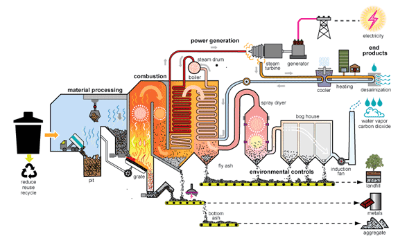
- Waste-to-Energy Plants: In waste-to-energy plants that burn municipal solid waste (MSW) or biomass, rotary kilns are used to combust the waste, often at very high temperatures. These plants can incorporate waste heat recovery systems to generate electricity. The captured energy not only helps power the plant but can also be fed into the grid, providing additional energy for surrounding communities.
Economic and Environmental Impacts
The adoption of waste heat recovery systems can lead to significant economic and environmental benefits:
- Cost Savings: By recovering waste heat and converting it into electricity, industries can drastically reduce their reliance on purchased energy. In some cases, the electricity generated can be used internally to power the plant, reducing operational costs. In other cases, excess electricity can be sold back to the grid, creating a potential new revenue stream for the business.
- Reduced Carbon Footprint: Utilizing waste heat for power generation reduces the need for additional fossil fuel consumption, which in turn reduces greenhouse gas emissions. This is a key benefit for companies aiming to reduce their environmental footprint and comply with environmental regulations, such as emissions limits or carbon tax initiatives.
- Improved Energy Security: Waste heat recovery systems help industrial facilities become more energy independent. By reducing reliance on external power suppliers, companies can better control their energy supply, particularly in areas where energy prices are volatile or unreliable. This increased energy security is especially important for energy-intensive industries, such as cement and steel manufacturing.
- Compliance with Regulations: As governments around the world implement stricter environmental regulations, industries that generate large amounts of waste heat face increasing pressure to improve energy efficiency and reduce emissions. Waste heat recovery systems can help these industries comply with regulations related to energy efficiency, emissions reduction, and sustainability goals.
Challenges and Future Prospects
While the benefits of waste heat recovery are clear, there are several challenges to widespread adoption:
- Initial Capital Costs: The installation of waste heat recovery systems requires significant upfront investment in equipment, engineering, and integration with existing industrial processes. This can be a barrier for small and medium-sized businesses or those with tight capital budgets. However, as technologies improve and economies of scale are realized, the costs of such systems are expected to decrease over time.
- System Integration: Integrating waste heat recovery systems with existing rotary kiln setups can be complex. Modifications to the kiln or surrounding infrastructure may be needed, which can disrupt operations and increase costs. A thorough analysis of the plant’s waste heat potential, process requirements, and system design is essential for ensuring successful implementation.
- Operational Challenges: Waste heat recovery systems require careful monitoring and maintenance to ensure optimal performance. Factors such as fluctuations in kiln operation, variations in waste heat temperature, and wear and tear on components can affect system efficiency. Advanced monitoring systems and predictive maintenance technologies are being developed to address these challenges and improve system reliability.
Conclusion
Generating electricity from waste heat in rotary kilns offers a powerful solution to improve energy efficiency, reduce operational costs, and decrease environmental impacts. As industries continue to embrace sustainability and move toward cleaner energy practices, the integration of waste heat recovery technologies will play a crucial role in advancing energy efficiency in energy-intensive sectors. The ongoing development of advanced systems, such as modular units, hybrid systems, and integrated CHP solutions, is making these technologies more accessible and cost-effective, paving the way for a more sustainable and energy-efficient industrial future.
As the push for energy efficiency and sustainability in industrial sectors intensifies, the utilization of waste heat recovery systems continues to evolve. The integration of such systems into rotary kiln operations is not only a way to cut energy costs but also a vital step toward reducing greenhouse gas emissions and enhancing overall plant performance. As we continue to explore the potential of these systems, it’s important to examine emerging trends, policy incentives, and future technologies that will drive their further adoption.
Emerging Trends in Waste Heat Recovery Systems
- Digitalization and Smart Systems: The integration of digital technologies into waste heat recovery systems is one of the key trends shaping the future of industrial energy efficiency. Advanced sensors, Internet of Things (IoT) devices, and cloud-based data platforms are being deployed to monitor real-time performance of waste heat recovery systems. These technologies allow for continuous performance tracking, predictive maintenance, and optimization, ensuring that systems operate at peak efficiency. AI-driven analytics can also predict fluctuations in waste heat production and optimize system operations to minimize energy waste and maximize power generation.
- Integration with Renewable Energy: As industries aim to reduce their carbon footprints and transition to cleaner energy sources, there is growing interest in integrating waste heat recovery systems with renewable energy technologies. For example, waste heat recovery can be combined with solar thermal or geothermal energy systems to create hybrid power plants. Solar thermal energy can provide additional heat to supplement the energy produced from rotary kiln waste heat, enhancing overall system efficiency. Similarly, waste heat could be stored in thermal energy storage systems to be used in conjunction with wind or solar power, providing a stable and continuous energy supply.
- Advanced Materials for Heat Transfer: Advances in material science are also making waste heat recovery more efficient. New heat transfer materials, including advanced alloys, ceramics, and coatings, are being developed to withstand higher temperatures and corrosive environments. These materials can significantly improve the efficiency of heat exchangers, making it easier to capture heat from rotary kilns and other high-temperature industrial processes. In addition, research into thermoelectric materials is exploring their potential to convert heat directly into electricity, further enhancing waste heat recovery.
- Waste Heat for District Heating: Instead of generating electricity directly from waste heat, some industrial facilities are focusing on using waste heat for district heating systems, especially in regions where large-scale industrial complexes are located near residential or commercial areas. Waste heat captured from rotary kilns can be used to supply hot water or steam to nearby buildings, reducing the need for fossil-fuel-powered heating systems. This approach not only benefits the industrial facility by increasing its overall energy efficiency but also provides a low-cost, low-emission energy source to local communities.
- Energy-as-a-Service (EaaS) Models: As the energy landscape shifts, some companies are moving away from traditional ownership of energy generation systems toward energy-as-a-service (EaaS) models. In this model, waste heat recovery and other energy systems are provided as a service, where third-party providers install, operate, and maintain the systems while the industrial facility pays for the electricity generated or energy saved. This model reduces the capital investment burden for businesses and makes advanced waste heat recovery systems more accessible to smaller enterprises. Over time, such partnerships can lead to increased adoption of waste heat recovery technologies across various industries.
Policy Incentives and Regulatory Support
Governments around the world are introducing policies to incentivize the adoption of waste heat recovery systems. These policies include financial incentives, tax credits, and regulatory mandates that encourage companies to invest in energy-efficient technologies. Some of the key policy drivers include:
- Carbon Emissions Reduction Targets: As global efforts to mitigate climate change intensify, industries are being pressured to reduce their carbon emissions. Waste heat recovery systems play a crucial role in this by helping companies minimize the amount of energy consumed from fossil fuels. Many countries, particularly in Europe and North America, have set ambitious targets for carbon reduction, and industries that invest in waste heat recovery can help meet these targets while benefiting from government incentives.
- Energy Efficiency Regulations: In addition to carbon emission reduction targets, many regions have enacted energy efficiency regulations that require industrial plants to reduce energy consumption. In some jurisdictions, energy-intensive industries like cement, steel, and chemicals are required to adopt energy-saving technologies and reduce their energy intensity. Waste heat recovery systems can help meet these requirements by enabling industries to reuse their own waste energy, thus lowering overall energy demand.
- Subsidies and Grants: Several governments offer financial incentives, such as grants or subsidies, to companies that invest in energy-saving technologies like waste heat recovery. These incentives help offset the high upfront costs of installation and integration, making the transition to waste heat recovery more financially viable for industrial operators. In some cases, grants are provided for research and development to advance the technology and improve its performance, further driving innovation in the field.
- International Climate Agreements: As part of international climate agreements, such as the Paris Agreement, countries are increasingly committed to transitioning to cleaner, more sustainable energy systems. Industrial sectors in these countries are expected to contribute to national climate goals. Waste heat recovery, which reduces dependence on fossil fuels and enhances energy efficiency, aligns with these goals, prompting governments to offer support and recognition for companies that adopt these technologies.
Future Technologies in Waste Heat Recovery
Looking ahead, several emerging technologies have the potential to revolutionize the way waste heat is captured and converted into usable energy:
- Direct Thermoelectric Conversion: Thermoelectric materials have the potential to directly convert heat into electricity without the need for a mechanical engine (like a steam turbine). These materials generate electricity through the Seebeck effect, which occurs when there is a temperature difference between two different conductive materials. Though current thermoelectric systems are less efficient than traditional methods like steam turbines, ongoing research is focused on improving the efficiency of thermoelectric generators, potentially making them viable for small-scale waste heat recovery systems in rotary kilns and other industrial applications.
- Heat-Driven Absorption Refrigeration: Absorption refrigeration is a cooling method that uses heat to drive the refrigeration cycle, rather than mechanical compressors. In industries like cement production, where rotary kilns generate significant waste heat, absorption refrigeration can be used for cooling purposes within the plant or for nearby district cooling applications. By utilizing waste heat for refrigeration, companies can increase the overall efficiency of their energy systems and reduce the need for electricity-intensive cooling technologies.
- Low-Grade Waste Heat Recovery: Another area of innovation is the recovery of low-grade waste heat (i.e., heat generated at lower temperatures, typically below 100°C) that has historically been difficult to utilize effectively. Technologies such as the Organic Rankine Cycle (ORC) are being adapted to capture this low-grade heat and convert it into electricity. This opens up opportunities for industries that produce large volumes of low-temperature waste heat, like food processing or textiles, to generate electricity and improve their energy efficiency.
- Hybrid Thermoelectric and Rankine Cycle Systems: Combining thermoelectric generators with traditional Rankine cycle systems could enhance waste heat recovery by addressing a broader temperature range. The thermoelectric system could handle low-temperature waste heat, while the Rankine cycle system could capture higher-temperature waste heat. This hybrid approach could maximize overall energy recovery and improve efficiency for a wide range of industrial applications.
Conclusion: The Future of Waste Heat Recovery
The future of generating electricity from waste heat in rotary kilns is bright, driven by technological innovations, supportive policies, and a global push toward sustainability. By harnessing the significant amounts of waste heat produced in energy-intensive industrial processes, businesses can reduce their environmental impact, improve energy efficiency, and cut operational costs. As the technology continues to evolve, especially with the integration of digitalization, renewable energy sources, and new materials, the potential for waste heat recovery will only continue to grow. Ultimately, industries that invest in these systems will not only benefit from improved performance but will also play a critical role in the global transition to a more sustainable and low-carbon energy future.
The oil and gas industry is a significant player in global energy markets, but it also generates large amounts of waste heat as a byproduct of exploration, extraction, refining, and transportation processes. This waste heat, often released through exhaust gases, flared gas, or thermal processes, represents a substantial, untapped resource that can be harnessed for power generation. The recovery and utilization of this waste heat can enhance energy efficiency, lower operational costs, and reduce the carbon footprint of the industry.
Overview of Heat Generation in the Oil and Gas Industry
In the oil and gas sector, heat is generated through a variety of activities, including:
- Upstream Processes (Exploration and Extraction): Exploration and extraction of oil and natural gas often involve drilling, well stimulation, and production processes that generate significant amounts of waste heat. During hydraulic fracturing (fracking) or oil extraction from offshore platforms, for example, large amounts of energy are required to operate pumps, compressors, and other equipment, and a significant portion of this energy is released as waste heat.
- Refining and Processing: Oil refining processes such as distillation, cracking, and hydroprocessing involve high temperatures. These processes generate substantial waste heat in the form of hot gases or heated fluids, which, if not recovered, are vented into the atmosphere. Refinery operations are particularly energy-intensive and present a prime opportunity for waste heat recovery.
- Natural Gas Compression and Transportation: The transportation and compression of natural gas, both onshore and offshore, require substantial amounts of energy. Compressors, pipelines, and LNG (liquefied natural gas) facilities are often sources of waste heat, as compressors in particular can operate at high temperatures. This heat is typically vented and wasted unless captured for recovery.
- Flaring and Venting: Flaring is a common practice in the oil and gas industry, where natural gas that cannot be captured or processed is burned off, typically in remote drilling operations. This process generates significant amounts of heat and carbon emissions, but the potential to capture and convert this heat into electricity through waste heat recovery systems could significantly reduce emissions and generate value.
Methods of Harnessing Waste Heat for Electricity Generation
There are several established and emerging technologies that can capture and convert waste heat from the oil and gas industry into electricity. The choice of technology depends on the temperature and nature of the waste heat, as well as the specific needs of the facility. These technologies include:
1. Organic Rankine Cycle (ORC)
The Organic Rankine Cycle (ORC) is a well-established technology for converting low- to medium-temperature waste heat into electricity. The ORC works similarly to a traditional steam Rankine cycle but uses an organic working fluid with a lower boiling point than water. This allows ORC systems to operate efficiently at lower temperatures, making them ideal for recovering heat from sources like natural gas compressors, flare stacks, or waste heat in refinery processes.
The ORC system is composed of several key components:
- Heat Exchanger: Captures the waste heat from the industrial process and transfers it to the organic working fluid.
- Turbine: The heated fluid expands, driving a turbine connected to a generator to produce electricity.
- Condenser: The expanded fluid is cooled and condensed back into a liquid before being recirculated.
Advantages of ORC systems include their ability to operate efficiently at lower temperatures and their scalability, making them suitable for a variety of oil and gas operations. However, their efficiency tends to decrease with very low-temperature waste heat sources, so they are best used with heat sources in the range of 150-400°C.
2. Steam Rankine Cycle (SRC)
For high-temperature waste heat recovery, particularly in refining and extraction processes, the Steam Rankine Cycle (SRC) remains one of the most effective methods for electricity generation. Similar to ORC, SRC utilizes a working fluid (in this case, water) that is heated by the waste heat and converted into steam. The steam expands through a turbine, which drives a generator to produce electricity.
SRC systems are highly efficient when capturing heat from sources with temperatures greater than 400°C, such as combustion exhaust gases or high-temperature refinery processes. However, they are typically more complex and require significant infrastructure for steam generation, cooling, and condensation.
3. Thermoelectric Generators (TEGs)
Thermoelectric generators are solid-state devices that directly convert heat into electricity using the Seebeck effect. When there is a temperature difference between two materials, a voltage is generated, which can be used to drive an electric current. TEGs can be used to recover waste heat from a variety of sources in the oil and gas industry, including exhaust gases, flare stacks, and even equipment surfaces.
While TEGs are not yet as widely used in large-scale applications as ORC or SRC, they offer several benefits:
- Compact and scalable: TEGs are relatively small and can be integrated into existing equipment without the need for large mechanical systems.
- Low maintenance: Because they have no moving parts, TEGs are less prone to wear and tear compared to traditional heat recovery systems.
- Efficiency improvements: Research into advanced thermoelectric materials is improving the efficiency of these devices, potentially making them more viable for industrial applications.
However, the efficiency of TEGs is currently lower than that of traditional Rankine systems, and the cost of high-performance materials can be a limiting factor. Ongoing research into new materials and nanotechnology is expected to improve the performance of thermoelectric systems over time.
4. Heat Recovery Steam Generators (HRSG)
Heat Recovery Steam Generators (HRSG) are commonly used in combined heat and power (CHP) systems to recover waste heat from flue gases. In the oil and gas industry, HRSGs are particularly useful in power generation facilities and combined-cycle plants, where high-temperature waste heat from gas turbines can be used to generate steam. This steam can then drive a steam turbine to generate additional electricity, significantly improving the overall efficiency of the power generation system.
HRSGs typically consist of:
- Heat exchangers: These transfer heat from exhaust gases to water or another fluid, generating steam.
- Steam turbine: The generated steam is used to drive a turbine and generate electricity.
- Cooling system: After passing through the turbine, the steam is cooled and condensed before being recirculated.
This technology is widely used in large-scale power plants and offers a high level of efficiency. However, it is typically most suitable for facilities with continuous high-temperature waste heat, such as gas turbines or large-scale oil and gas processing plants.
5. Flare Gas Recovery Systems
Flaring is a major source of wasted energy in the oil and gas industry, especially in remote areas where infrastructure for capturing and transporting natural gas is not available. Flare gas recovery systems can capture the flared gas and use it to generate electricity.
These systems use combustion engines or turbines to burn the captured flare gas, converting its energy into mechanical power that drives a generator. This process not only reduces the need for flaring but also provides a useful power source for remote oil and gas operations. Additionally, the recovered energy can be used for internal consumption, such as powering equipment or providing heat for other industrial processes.
Flare gas recovery systems are typically employed in offshore oil platforms, gas gathering stations, and remote production sites, where they help minimize the environmental impact of gas flaring while providing a reliable and cost-effective source of electricity.
Economic and Environmental Benefits
The recovery of waste heat in the oil and gas industry provides both economic and environmental benefits:
1. Cost Savings
- Reduced Energy Consumption: By recovering waste heat and converting it into electricity, oil and gas companies can reduce their dependence on external power sources, lowering energy bills.
- Flare Gas Utilization: By recovering flare gas and converting it to electricity, companies can reduce or eliminate the need for expensive natural gas imports or diesel generators, especially in remote locations.
2. Reduced Carbon Emissions
- Lower Carbon Footprint: By capturing and converting waste heat instead of relying on fossil fuels for electricity generation, the carbon emissions of oil and gas operations are reduced. This can help companies meet emissions reduction targets and align with global sustainability goals.
- Flaring Reduction: Recovering flare gas for power generation reduces the amount of gas flared into the atmosphere, helping to mitigate harmful greenhouse gas emissions.
3. Improved Sustainability
- Waste heat recovery supports the oil and gas industry’s transition toward more sustainable operations. It makes use of otherwise wasted energy, reducing resource consumption and improving the overall energy efficiency of operations.
Conclusion
Generating electricity from waste heat in the oil and gas industry is a growing opportunity for improving energy efficiency, reducing operational costs, and minimizing environmental impacts. The implementation of technologies like the Organic Rankine Cycle, Thermoelectric Generators, Steam Rankine Cycles, and flare gas recovery systems can help companies convert waste heat into usable energy, enabling them to reduce reliance on external energy sources, improve sustainability, and meet regulatory demands. As the industry continues to prioritize energy efficiency and environmental responsibility, the adoption of waste heat recovery technologies will play a crucial role in shaping a more sustainable future for the oil and gas sector.
As the demand for energy efficiency and sustainability continues to rise, the oil and gas industry is increasingly focused on reducing its carbon footprint and optimizing energy consumption. The recovery and use of waste heat represent one of the most practical and impactful strategies to achieve these objectives. To further elaborate, there are several key aspects to consider as the industry moves forward in harnessing waste heat for electricity generation.
1. Technological Advancements and Innovations in Heat Recovery
While traditional methods for waste heat recovery like ORC, SRC, and HRSG systems are well-established, new and emerging technologies are helping to further optimize the process and increase energy generation. Advancements in materials, system integration, and efficiency improvements are continuously enhancing the potential for oil and gas companies to generate electricity from waste heat. Some notable innovations include:
a. High-Temperature Materials
One of the challenges in waste heat recovery is the need for materials that can withstand the extremely high temperatures found in oil and gas operations, particularly in refinery and extraction processes. Research into advanced heat-resistant materials, including high-temperature alloys and ceramics, is improving the longevity and efficiency of heat exchangers and turbines. These materials can handle higher temperatures more effectively, leading to greater energy capture and efficiency in heat recovery systems.
b. Hybrid Systems
Hybrid systems that combine different methods of waste heat recovery—such as pairing ORC with traditional steam turbines or thermoelectric generators—are gaining attention as they can maximize electricity generation across a wider range of temperatures. Hybrid systems have the potential to capture both low- and high-temperature heat from various sources in an oil or gas facility, increasing overall efficiency and reducing waste heat loss.
c. Closed-Loop Heat Recovery
Closed-loop systems are gaining popularity in situations where waste heat cannot be directly used for power generation due to environmental or operational concerns. In a closed-loop system, heat is captured and stored in a secondary fluid, which is then used to power a turbine or generate electricity through other means. These systems have the advantage of preventing waste heat from escaping into the environment and can be designed to integrate seamlessly into existing infrastructure without significant modifications.
d. Energy Storage Integration
Integrating energy storage systems with waste heat recovery technologies is another area of development. Thermal energy storage (TES) can store excess heat generated during peak demand periods, which can then be converted into electricity when needed. This integration helps smooth out fluctuations in power generation and improves the reliability of electricity produced from waste heat.
2. Operational Efficiency and Cost Optimization
The recovery of waste heat does not just generate electricity—it also enhances the overall operational efficiency of oil and gas facilities. By reducing energy consumption and reliance on external power sources, companies can significantly lower operational costs.
a. Fuel Savings
In remote oil and gas operations, where access to grid electricity is limited or nonexistent, waste heat recovery systems can replace or reduce the need for diesel generators and other expensive power sources. These generators are typically used for backup power or to meet the electricity demand of facilities, and their fuel costs can be a major expense. By utilizing waste heat to generate electricity on-site, companies can save fuel and reduce logistical costs associated with fuel transportation.
b. Efficiency Gains in Production
Energy efficiency is a critical factor in maximizing production output and minimizing costs in the oil and gas sector. By recovering waste heat from processes such as compression, refining, and fracking, oil and gas operators can reduce the energy required to maintain operations, leading to better overall efficiency. Additionally, recovered energy can be used to power other processes within the plant, such as heating, cooling, or even the operation of electrical equipment, further optimizing energy consumption.
c. Lifecycle Cost Benefits
While the initial investment in waste heat recovery systems can be substantial, the long-term financial benefits typically outweigh the upfront costs. By reducing the reliance on purchased electricity or fuel, companies can recover their investment over time through energy savings. Moreover, waste heat recovery systems have a relatively low operational and maintenance cost, especially when compared to traditional power generation methods, further enhancing their economic feasibility.
3. Environmental and Regulatory Compliance
As the global regulatory landscape becomes more stringent in terms of emissions reduction, waste heat recovery systems offer a clear path for oil and gas companies to meet both local and international environmental standards.
a. Carbon Emissions Reduction
The oil and gas industry is one of the largest contributors to global greenhouse gas emissions. Flare gas, in particular, is a significant source of methane emissions, a potent greenhouse gas. By capturing flare gas and converting it into electricity, the industry can mitigate the harmful environmental impacts of flaring and reduce carbon emissions.
Furthermore, using waste heat to generate electricity instead of relying on fossil fuel-powered generators or grid electricity can significantly lower the overall carbon footprint of operations. Companies can achieve carbon reduction goals set by international climate agreements, such as the Paris Agreement, and demonstrate their commitment to sustainability.
b. Compliance with Emission Standards
Governments worldwide are tightening regulations around emissions from industrial facilities, including the oil and gas sector. In many regions, companies are required to reduce their emissions by a certain percentage each year. The installation of waste heat recovery systems provides a cost-effective way to comply with these regulations by decreasing the need for fuel combustion and reducing greenhouse gas emissions.
Many oil and gas companies are also being incentivized through tax credits, subsidies, and regulatory exemptions for investing in cleaner energy technologies. Waste heat recovery falls within the category of low-carbon technologies and can qualify companies for such incentives, further improving the financial viability of these systems.
c. Reputation and Corporate Responsibility
As public awareness about climate change and sustainability grows, the reputation of oil and gas companies is increasingly tied to their environmental practices. Companies that invest in waste heat recovery and other energy-efficient technologies demonstrate a commitment to reducing their environmental impact, which can strengthen their brand image and appeal to environmentally-conscious investors, stakeholders, and customers.
4. Challenges and Barriers to Adoption
While the potential for waste heat recovery in the oil and gas industry is significant, there are several challenges that can hinder the widespread adoption of these technologies.
a. High Initial Costs
One of the main barriers to the implementation of waste heat recovery systems is the high capital expenditure required for their installation. Although the long-term benefits of reduced energy costs and lower carbon emissions are clear, the initial cost can be prohibitive for some companies, particularly in smaller operations or in regions where energy prices are relatively low.
b. Technical Complexity
Integrating waste heat recovery systems into existing oil and gas infrastructure can be technically complex. The systems often require specialized components, such as heat exchangers, turbines, and generators, which need to be customized to fit the specific operating conditions of the facility. This can increase both the cost and the time required for installation.
c. Operational Variability
Waste heat recovery systems are dependent on the availability of consistent and adequate heat. In some oil and gas operations, the amount of waste heat produced can fluctuate due to changes in production processes, maintenance schedules, or seasonal variations. This variability can make it difficult to design waste heat recovery systems that operate efficiently at all times. Additionally, in situations where waste heat is intermittent or low-grade, the economics of recovery may not justify the investment.
d. Regulatory and Policy Uncertainty
In some regions, the regulatory environment surrounding waste heat recovery technologies is still developing, which can create uncertainty for companies considering these investments. Clear and stable policies, as well as government incentives for waste heat recovery, are essential for encouraging wider adoption of these systems across the oil and gas sector.
5. Looking Ahead: The Future of Waste Heat Recovery in the Oil and Gas Industry
The future of waste heat recovery in the oil and gas industry looks promising, with continued advancements in technology, growing regulatory pressures, and a greater emphasis on sustainability. As waste heat recovery technologies become more efficient and cost-effective, their adoption is likely to increase, helping the industry meet its energy needs while also reducing its environmental impact.
Further innovations in material science, system integration, and digital monitoring technologies will continue to improve the performance and economics of waste heat recovery. In particular, hybrid systems that combine multiple technologies to capture and utilize waste heat will offer new opportunities for maximizing energy efficiency.
Ultimately, the integration of waste heat recovery systems will play a crucial role in the oil and gas industry’s efforts to reduce emissions, increase energy efficiency, and contribute to a more sustainable energy future.
6. The Role of Digitalization and Smart Technologies in Waste Heat Recovery
Digital technologies are revolutionizing the way industries manage energy, and the oil and gas sector is no exception. In the context of waste heat recovery, smart technologies can enhance system performance, improve efficiency, and provide real-time data for optimization. The integration of digital tools is making waste heat recovery more intelligent, adaptive, and cost-effective.
a. Advanced Sensors and IoT
The use of advanced sensors and Internet of Things (IoT) devices allows for continuous monitoring of temperature, pressure, and flow rates in waste heat recovery systems. These sensors collect real-time data from various parts of the system, providing operators with actionable insights on system performance. By identifying inefficiencies, such as heat loss or suboptimal operation, the system can be adjusted dynamically to maximize energy recovery.
For example, sensors in heat exchangers can detect temperature fluctuations that may indicate fouling or other operational issues, prompting immediate maintenance actions. This predictive capability ensures that waste heat recovery systems operate at peak efficiency, avoiding costly downtime and reducing maintenance costs.
b. Data Analytics and Artificial Intelligence (AI)
Data analytics and AI are increasingly being applied to optimize waste heat recovery systems. By processing large volumes of data from sensors, AI algorithms can identify patterns, predict system performance under different conditions, and make real-time adjustments to improve energy capture. For instance, AI can predict fluctuations in waste heat availability and adjust recovery strategies accordingly, ensuring maximum power generation even in variable operational conditions.
Moreover, machine learning algorithms can enhance predictive maintenance by identifying trends that indicate impending equipment failure. This proactive approach to maintenance helps avoid unplanned shutdowns and reduces the risk of costly repairs, extending the lifespan of equipment and optimizing the system’s return on investment.
c. Digital Twins
A digital twin is a virtual replica of a physical asset or system that can simulate real-time conditions and performance. In the case of waste heat recovery systems, digital twins can model the entire heat recovery process, from heat capture to electricity generation. By creating a virtual model of the system, operators can simulate different scenarios, test system configurations, and optimize performance before implementing changes in the real-world system.
Digital twins can also be used to predict the performance of waste heat recovery systems under varying operational conditions, such as changes in the production process or environmental factors. This capability enables better decision-making, more accurate system design, and improved maintenance planning.
7. Industry Case Studies and Applications
Several companies and oil and gas operations have already implemented waste heat recovery technologies, demonstrating the practical benefits and value of these systems. Some notable examples include:
a. BP’s Waste Heat Recovery Project in the North Sea
BP has successfully implemented a waste heat recovery system on one of its North Sea platforms. The project uses a combination of ORC and other heat recovery technologies to capture waste heat from gas turbines and other equipment on the platform. The recovered heat is then converted into electricity, providing a significant portion of the platform’s power needs. This project has resulted in reduced fuel consumption, lower emissions, and a more reliable power supply.
b. Shell’s Motiva Refinery in the U.S.
Shell’s Motiva refinery in the United States is another example of successful waste heat recovery in the oil and gas sector. The refinery utilizes an HRSG system to recover heat from flue gases generated during refining operations. The recovered heat is used to generate steam, which drives a steam turbine to produce electricity. This system has helped the refinery reduce its reliance on external power sources and improve energy efficiency, while also reducing greenhouse gas emissions from the facility.
c. Statoil’s Waste Heat Recovery System in Offshore Platforms
Statoil (now Equinor) has implemented a waste heat recovery system on one of its offshore platforms in the North Sea. The system captures heat from gas turbines and uses it to generate electricity through an ORC system. This project has not only reduced fuel consumption and operational costs but has also provided a blueprint for similar projects on other offshore platforms. The successful implementation of waste heat recovery on offshore platforms shows the potential for these systems in harsh, remote environments.
8. The Future of Waste Heat Recovery: Challenges and Opportunities
Despite the progress made in waste heat recovery, there are still some challenges that the oil and gas industry must overcome to fully unlock the potential of this technology.
a. Overcoming Economic Barriers
The primary barrier to widespread adoption of waste heat recovery systems remains the initial capital investment. While the long-term financial benefits are evident, the upfront costs of purchasing and installing waste heat recovery systems can be significant. Many companies are hesitant to invest in these systems, especially when the return on investment may take several years to materialize.
However, as technologies improve and become more cost-effective, it is likely that the economic barriers will continue to decrease. Additionally, government incentives, subsidies, and carbon credit systems aimed at reducing emissions may provide financial support for the implementation of waste heat recovery technologies.
b. Expanding the Use of Hybrid and Integrated Systems
As the oil and gas industry continues to explore ways to enhance energy efficiency, hybrid and integrated systems will play a larger role in waste heat recovery. These systems combine multiple technologies to capture and utilize heat from various sources within a facility. For example, a hybrid system may combine an ORC unit with a conventional steam turbine to maximize electricity generation from both high and low-temperature waste heat.
The integration of waste heat recovery systems with renewable energy sources, such as solar or wind power, could also help companies create more sustainable and resilient energy systems. For example, excess heat captured from a flare stack could be stored or used to power a solar energy system, creating a hybrid solution that reduces both waste heat and emissions.
c. Regulatory Pressure and the Push Toward Carbon Neutrality
As global demand for cleaner energy continues to rise, oil and gas companies will face increasing pressure to reduce their carbon footprint. The adoption of waste heat recovery technologies will become more critical as regulatory bodies introduce stricter emissions regulations and governments implement carbon pricing mechanisms. To meet these regulatory pressures, companies must not only focus on reducing emissions through waste heat recovery but also work on improving the overall energy efficiency of their operations.
The growing push for carbon neutrality will drive investment in waste heat recovery technologies and other energy-efficient solutions, creating new opportunities for innovation and growth. Companies that invest in these technologies now will be better positioned to comply with future regulatory requirements and capitalize on the demand for cleaner energy.
Conclusion: A Sustainable and Efficient Future for the Oil and Gas Industry
The oil and gas industry faces a significant challenge in balancing energy production with environmental responsibility. Waste heat recovery provides a unique opportunity to reduce the industry’s carbon footprint while simultaneously improving energy efficiency and reducing operational costs. The continued development and adoption of waste heat recovery technologies, driven by advancements in digitalization, material science, and system integration, will play a pivotal role in shaping the future of the industry.
As oil and gas companies increasingly recognize the financial and environmental benefits of waste heat recovery, the industry is poised to make significant strides toward sustainability. By leveraging existing technologies and pursuing innovative solutions, companies can reduce emissions, increase energy security, and move closer to a more sustainable energy future.
Generating Electricity Using Waste Heat from the Mining of Minerals
The mining industry, particularly the extraction of minerals, is an energy-intensive process. With the need for heavy machinery, high temperatures, and constant operation in mining facilities, vast amounts of waste heat are produced at various stages of the mining process. Capturing and converting this waste heat into electricity is becoming a key strategy for improving energy efficiency, reducing operational costs, and lowering the environmental impact of mining operations. This practice not only helps in the efficient use of resources but also contributes to sustainable mining practices.
1. Sources of Waste Heat in the Mining Industry
Mining operations generate waste heat at various stages, primarily during the following activities:
a. Ore Processing
Ore processing, such as crushing, grinding, flotation, and smelting, involves high temperatures that lead to the production of significant amounts of waste heat. During the smelting process, for example, the heat from furnaces or kilns used to melt ore can be substantial. Often, this heat is vented into the atmosphere or dissipated without being utilized.
b. Diesel and Electricity-Driven Equipment
Mining facilities, especially those operating in remote locations, rely heavily on diesel-powered generators and heavy equipment to power their operations. These machines, such as trucks, drills, and excavation equipment, release a large amount of waste heat through their engines. In addition, electricity used for the mine’s operational activities often comes from external sources, and the production and distribution of this electricity may result in thermal losses, which can be recovered.
c. Geothermal Heat
In some mining operations, especially those that mine in geologically active regions, natural geothermal heat from the earth can be tapped. This waste heat can come from the ground itself or be generated as part of geothermal energy extraction for processes like heating water used in ore processing.
d. Ventilation Systems
In underground mining operations, ventilation systems are necessary to ensure that miners have access to fresh air and to regulate the temperature and humidity in tunnels. These ventilation systems often release warm air from deep underground, which is a valuable source of waste heat.
2. Technologies for Capturing and Converting Waste Heat
The conversion of waste heat into electricity in the mining industry requires specialized technology to capture, store, and convert the heat into usable electrical power. Several technologies are currently in use or under development for this purpose:
a. Organic Rankine Cycle (ORC) Systems
The ORC system is one of the most commonly used methods for converting low-grade waste heat into electricity. The system works by using an organic fluid with a low boiling point, which allows it to vaporize at relatively low temperatures. The organic fluid is heated by the waste heat from mining operations, causing it to vaporize and drive a turbine connected to a generator, thus producing electricity. ORC systems are well-suited for mining operations because they can efficiently operate at low to medium temperatures, typically between 80°C and 350°C, which is common in many mining waste heat sources.
ORC technology is particularly effective in scenarios where the waste heat is not hot enough for traditional steam turbines but is still significant enough to be utilized for power generation. In addition, the compact nature of ORC systems makes them ideal for installation in remote or space-constrained mining environments.
b. Steam Rankine Cycle (SRC) Systems
For mining operations where higher temperature waste heat is available (typically above 300°C), the Steam Rankine Cycle (SRC) system can be used. In this system, waste heat is used to produce steam, which drives a steam turbine connected to a generator. SRC systems are capable of generating electricity from higher temperature waste heat, making them suitable for operations such as ore smelting, where the heat produced can exceed 600°C.
One of the key benefits of SRC systems is their ability to produce larger quantities of electricity compared to ORC systems. However, they require more complex and expensive infrastructure, including a boiler to produce steam, which can increase the initial capital cost of the project.
c. Thermoelectric Generators (TEGs)
Thermoelectric generators (TEGs) are devices that directly convert heat into electricity through the Seebeck effect, where a temperature difference across a material leads to the generation of an electrical voltage. While still in the early stages of commercialization, TEGs have the potential to be used in mining operations where waste heat is abundant but difficult to capture using traditional methods.
TEGs are relatively small and modular, which makes them suitable for use in mining environments where space and maintenance considerations are important. However, the efficiency of TEGs is currently lower compared to ORC and SRC systems, and they are typically used for smaller-scale applications or as supplementary power sources.
d. Heat Recovery Steam Generators (HRSG)
Heat Recovery Steam Generators (HRSG) are specialized heat exchangers that recover the waste heat from exhaust gases (often from combustion turbines) and use it to produce steam. In mining operations that use combustion turbines for power generation, HRSG units can be used to capture the waste heat from the exhaust and convert it into additional electricity.
HRSG systems are particularly useful in mining operations where the exhaust gas temperatures from power-generating equipment are sufficiently high to produce steam. HRSG units are often paired with steam turbines to generate power, increasing the overall efficiency of the power generation process.
e. Combined Heat and Power (CHP) Systems
Combined Heat and Power (CHP) systems, also known as cogeneration, generate both electricity and useful thermal energy from a single fuel source. In the context of mining, CHP systems can be employed to utilize waste heat generated during ore processing or from power generation units like diesel engines or gas turbines. The system uses the waste heat to generate additional electricity or to provide heating for other operational needs, such as heating water or powering drying processes.
CHP systems are highly efficient, as they reduce the need to generate separate electricity and thermal energy. This efficiency helps to reduce overall energy consumption and lowers operational costs, making CHP systems attractive for energy-intensive industries like mining.
3. Economic and Environmental Benefits
a. Reduced Operational Costs
Mining operations are energy-intensive, and energy costs represent a significant portion of overall operational expenses. By capturing and converting waste heat into electricity, mines can reduce their reliance on external power sources, such as grid electricity or diesel generators. This reduction in energy purchases can result in substantial cost savings, especially in remote mining operations where access to affordable electricity can be limited.
Moreover, the ability to generate electricity from waste heat can reduce the need for backup power sources, such as diesel generators, which can be costly to operate and maintain. By relying more on self-generated electricity, mining companies can enhance the economic viability of their operations.
b. Environmental Impact Reduction
The mining industry is a major contributor to greenhouse gas emissions, primarily due to energy consumption and the use of fossil fuels in power generation. By capturing waste heat and converting it into electricity, mining operations can reduce their carbon footprint and contribute to environmental sustainability. These waste heat recovery systems help to minimize emissions by decreasing the need for fossil fuel-based power generation, such as coal or natural gas.
In addition to reducing CO2 emissions, waste heat recovery also minimizes the environmental impact associated with the release of excess heat into the atmosphere. In some cases, mining operations can even use the recovered heat to reduce water usage by minimizing the need for cooling systems that rely on large amounts of freshwater.
c. Increased Energy Efficiency
The use of waste heat recovery technologies in the mining industry helps to improve the overall energy efficiency of operations. By capturing and reusing heat that would otherwise be lost, mining companies can maximize the value derived from every unit of energy consumed. This efficiency not only improves the bottom line but also helps to reduce the overall energy demand of mining operations.
In many cases, the heat that would otherwise be wasted is sufficient to power mining facilities for extended periods, reducing the amount of energy purchased from external sources. By maximizing energy efficiency, mining companies can operate more sustainably, reduce energy waste, and align with global sustainability goals.
4. Challenges and Barriers to Adoption
Despite the clear economic and environmental benefits of waste heat recovery in the mining industry, several challenges remain that can hinder the widespread adoption of these technologies:
a. High Initial Capital Investment
One of the main barriers to the adoption of waste heat recovery technologies in the mining industry is the high upfront cost of implementing these systems. The installation of heat recovery systems, turbines, generators, and supporting infrastructure requires a significant investment. While the long-term savings can justify the initial cost, many mining companies may be reluctant to invest in these systems, especially in volatile market conditions.
b. Technological Compatibility
In some mining operations, particularly older or more traditional sites, the integration of waste heat recovery systems can be challenging. Existing equipment may not be designed to work with modern waste heat recovery technologies, and retrofitting systems to capture and convert waste heat may be technically complex and costly. Compatibility issues may also arise if the temperature or nature of the waste heat varies significantly across different stages of the mining process.
c. Maintenance and Operational Complexity
While waste heat recovery systems can provide substantial benefits, they also require regular maintenance and skilled operators to ensure that they function optimally. The complexity of these systems can increase the operational burden on mining companies, especially in remote or harsh environments where access to skilled personnel and spare parts may be limited.
d. Variability of Waste Heat Sources
The availability and consistency of waste heat are not always guaranteed. Waste heat generation can fluctuate based on changes in mining processes, seasonal variations, and the specific energy demands of the operation. In some cases, the heat may not be available at the right times for optimal electricity generation. This variability makes it challenging to design waste heat recovery systems that can always operate efficiently, especially in mines with fluctuating production rates.
5. Conclusion: A Path to Sustainable Mining
Waste heat recovery presents a significant opportunity for the mining industry to reduce energy consumption, lower operational costs, and mitigate environmental impacts. As the mining industry faces increasing pressure to operate more sustainably, technologies for capturing and converting waste heat into electricity will play a key role in shaping the future of the industry.
While challenges remain, advancements in waste heat recovery technologies, such as ORC, SRC, and CHP systems, offer promising solutions for mining companies to generate electricity from previously untapped sources of waste heat. The integration of these systems, along with ongoing innovations in energy efficiency, will enable the mining sector to reduce its reliance on external power sources, lower its carbon footprint, and contribute to a more sustainable energy future.
As the industry continues to embrace new technologies and optimize energy use, waste heat recovery has the potential to become a cornerstone of sustainable mining operations worldwide.
6. Future Outlook and Opportunities for Waste Heat Recovery in Mining
As the global mining industry faces mounting pressure to improve sustainability, reduce carbon emissions, and enhance energy efficiency, the future of waste heat recovery technologies looks increasingly promising. These systems not only help minimize the environmental impact of mining but also present a unique opportunity to lower operational costs and increase the overall competitiveness of mining operations.
a. Innovation in Energy Storage and Hybrid Systems
The future of waste heat recovery in mining may see the development of more advanced energy storage technologies to address the intermittency of waste heat availability. By incorporating energy storage systems, such as batteries or thermal storage solutions, mining operations can capture and store surplus electricity generated during periods of abundant waste heat. This stored energy can then be used when the heat recovery system is not producing enough power to meet the demand, ensuring a more stable and reliable power supply.
Hybrid systems that combine waste heat recovery with renewable energy sources like solar or wind power are another promising direction for the mining industry. Such systems can increase the resilience of mining operations by diversifying energy sources and reducing the reliance on fossil fuels. For example, excess waste heat could be used to power a geothermal or solar-powered heat pump, providing additional electricity generation while decreasing the overall environmental footprint of mining activities.
b. Government Policies and Incentives
As governments worldwide intensify efforts to combat climate change and promote sustainability, there is growing support for the adoption of energy-efficient technologies. Many countries have introduced policies, subsidies, tax incentives, and grants to encourage industries to adopt waste heat recovery systems and other clean technologies. The mining industry stands to benefit from these incentives, particularly as regulations governing emissions become more stringent.
The global push for net-zero emissions by 2050 has already led to an increase in the number of mining companies investing in green technologies. In regions where carbon taxes or emissions trading schemes are in place, waste heat recovery systems can help companies meet their emission reduction targets while improving energy efficiency. For example, the EU Emissions Trading System (ETS) and similar programs in other regions incentivize mining companies to reduce their greenhouse gas emissions by rewarding those that implement energy-saving technologies like waste heat recovery.
c. Advancements in Materials Science and Heat Exchange Technologies
Another area of significant development is the improvement of materials used for heat exchange in recovery systems. Advanced materials, such as high-efficiency heat exchangers, better insulation materials, and corrosion-resistant alloys, are being developed to withstand the harsh environments typical in mining operations. These advancements make heat recovery systems more durable and efficient, which can lead to lower maintenance costs and higher energy conversion rates.
Nanotechnology is also being explored to improve the heat transfer efficiency of heat exchangers. By utilizing nanoscale coatings or structures, it’s possible to create more effective heat exchangers that operate at higher temperatures and efficiencies. These innovations could play a crucial role in making waste heat recovery systems more economically viable for large-scale mining operations.
d. Decarbonizing Heavy-Duty Mining Equipment
Waste heat recovery can also help address the challenge of decarbonizing the heavy-duty equipment used in mining. Large mining trucks, loaders, and other vehicles consume vast amounts of diesel fuel, contributing to significant greenhouse gas emissions. By integrating waste heat recovery systems into these vehicles, it’s possible to reduce fuel consumption and lower emissions.
Additionally, some mining companies are exploring hybrid or fully electric vehicles that can utilize waste heat recovery to improve efficiency. For example, an electric mining truck could use the waste heat generated by its braking system to charge its batteries or provide power for onboard systems, reducing the need for external charging sources.
7. Conclusion: Transforming Mining Through Waste Heat Recovery
Waste heat recovery technologies offer an exciting pathway for the mining industry to achieve greater energy efficiency, reduce operational costs, and minimize environmental impact. By tapping into the vast amounts of waste heat generated during various stages of the mining process, companies can convert previously lost energy into useful power, contributing to a more sustainable future for the industry.
As technological advancements continue to evolve and global sustainability pressures increase, the adoption of waste heat recovery systems in mining will become more widespread. The integration of hybrid energy systems, advancements in materials science, and government incentives will further accelerate the implementation of these technologies, allowing the mining sector to align more closely with global decarbonization goals.
While challenges remain, such as high upfront costs and the need for infrastructure upgrades, the long-term economic and environmental benefits of waste heat recovery systems will make them an increasingly attractive solution. By investing in these technologies now, mining companies can not only reduce their environmental footprint but also position themselves as leaders in sustainable mining practices for the future. As innovation continues, the integration of waste heat recovery systems into mining operations will play a crucial role in shaping the industry’s path toward greater energy efficiency and environmental stewardship.
8. Scaling Waste Heat Recovery in Mining: The Path to Industry-Wide Adoption
As waste heat recovery technologies prove to be effective in reducing energy costs and emissions, scaling these systems across the mining industry presents both opportunities and challenges. For mining companies to adopt waste heat recovery on a broader scale, several considerations must be addressed, including infrastructure requirements, cost-benefit analysis, and alignment with broader industry goals.
a. Industry Collaboration and Knowledge Sharing
One of the key strategies for scaling waste heat recovery in the mining industry is fostering collaboration between industry stakeholders. By sharing knowledge, best practices, and lessons learned, mining companies can accelerate the adoption of waste heat recovery technologies. This collaboration can take place at various levels, including between mining companies, equipment manufacturers, technology providers, and research institutions.
Industry consortia and forums focused on energy efficiency and sustainability can serve as platforms for discussing new technologies, as well as providing support for companies navigating the technical and financial complexities of implementing waste heat recovery systems. Collaborative projects and joint ventures can also help mitigate the financial burden of investing in such technologies, especially for smaller operators.
In some regions, government-backed research and development initiatives are encouraging collaboration within the mining industry to improve the performance and cost-effectiveness of waste heat recovery systems. These efforts not only help reduce technological risks but also encourage a wider adoption of these systems by demonstrating their viability in different mining environments.
b. Modular and Scalable Solutions for Small-Scale Operations
For smaller mining operations, the implementation of large-scale waste heat recovery systems can be cost-prohibitive due to the substantial upfront capital required. To address this issue, modular and scalable waste heat recovery solutions are becoming more popular. These smaller, more flexible systems allow mining operations to start with a manageable investment and gradually expand their waste heat recovery capacity as the operation grows or as energy needs increase.
Modular systems can be designed to capture waste heat from specific parts of the mining process, such as smelting or ore grinding, and can be integrated into existing infrastructure without requiring major retrofits. The modularity of these systems also makes it easier to adopt and upgrade over time, reducing the initial financial commitment and allowing mining companies to align the system’s growth with their operational needs.
Scalable systems are particularly useful in remote or smaller mining sites where energy needs may fluctuate based on production schedules or seasonal demand. These systems can be fine-tuned to match the waste heat available at any given time, ensuring optimal energy capture and conversion efficiency without overbuilding infrastructure.
c. Financial Incentives and Government Support
To overcome the financial barrier of initial investment, many governments offer financial incentives, including subsidies, tax credits, and low-interest loans for energy efficiency projects. These incentives help mining companies offset the upfront capital costs of installing waste heat recovery systems, making them more attractive from a financial perspective.
Additionally, some countries have introduced carbon pricing mechanisms or cap-and-trade systems that penalize companies based on the amount of carbon dioxide (CO2) they emit. By implementing waste heat recovery systems, mining companies can reduce their emissions and lower their carbon tax liabilities, creating a financial incentive to invest in these technologies.
Global organizations and industry bodies are also playing a role in supporting the transition toward sustainable mining. By aligning with international frameworks such as the United Nations Sustainable Development Goals (SDGs), mining companies that adopt waste heat recovery technologies may also benefit from increased access to sustainable finance, grants, or environmental impact reporting credits.
d. Education and Training for a Skilled Workforce
The successful implementation of waste heat recovery technologies in the mining industry requires a skilled workforce capable of maintaining and operating these complex systems. As the adoption of these systems grows, so too does the demand for technicians and engineers with expertise in energy efficiency and heat recovery systems.
Training programs, certifications, and partnerships with academic institutions can help develop the workforce needed to support the operation of these systems. Companies that invest in training their employees can improve the overall effectiveness of their waste heat recovery programs, ensuring systems are optimized for performance and reducing the risk of costly failures or inefficiencies.
Some mining companies are already collaborating with universities and technical colleges to create specialized curricula focused on energy efficiency and waste heat recovery technologies. By working with educational institutions, the mining industry can help nurture a talent pipeline that ensures the sustainability of these energy solutions.
e. Long-Term Return on Investment (ROI) Considerations
Though waste heat recovery systems typically involve significant upfront costs, the long-term return on investment (ROI) can make them financially viable in the long run. Many mining companies are increasingly viewing energy efficiency as a strategic investment rather than just a cost-saving measure. Waste heat recovery systems can provide a steady stream of cost savings through reduced energy purchases, decreased fuel consumption, and lower carbon tax liabilities.
In addition to direct cost savings, the enhanced environmental performance of mining operations can translate into long-term benefits, including improved public perception, better relationships with regulators, and increased access to sustainable financing. By incorporating waste heat recovery into their energy management strategies, mining companies can improve their financial position while also aligning with global trends toward decarbonization.
Mining companies that invest in waste heat recovery early on can also benefit from the competitive advantage of being early adopters of sustainable technologies. As sustainability becomes an increasing priority for investors and consumers, those who are leading the way in waste heat recovery may be more attractive to environmentally-conscious investors, customers, and partners.
f. Future Market Potential
As global demand for minerals continues to rise, driven by industries like electronics, renewable energy, and electric vehicles, the mining sector faces growing scrutiny over its environmental impact. Waste heat recovery technologies are poised to play a crucial role in helping the mining industry meet the energy demands of the future while reducing its environmental footprint.
The ongoing shift toward more energy-efficient and sustainable practices in mining presents a significant market opportunity for companies developing and manufacturing waste heat recovery technologies. As the market for these systems expands, further advancements in efficiency, cost reduction, and system integration will help increase their adoption across the mining industry.
9. Conclusion: A Greener Future for Mining with Waste Heat Recovery
Waste heat recovery holds the key to unlocking a more sustainable and energy-efficient future for the mining industry. By capturing and converting waste heat into electricity, mining operations can significantly reduce their energy costs, lower emissions, and improve their overall sustainability performance. The adoption of waste heat recovery technologies is not just a means of improving operational efficiency—it is also a critical step toward meeting global decarbonization goals and addressing the increasing environmental pressures faced by the mining sector.
While challenges remain, such as high initial capital costs, technological integration, and the need for skilled workers, the long-term benefits of waste heat recovery are clear. Through innovation, government support, and industry collaboration, mining companies can scale waste heat recovery solutions and realize their full potential. In doing so, the mining industry will not only enhance its bottom line but also contribute to a cleaner, greener, and more sustainable world.
By embracing these technologies, the mining industry can demonstrate its commitment to sustainable practices, positioning itself as a key player in the global transition to a low-carbon future. As waste heat recovery systems continue to evolve, they will become an integral part of the mining industry’s efforts to optimize energy use, reduce emissions, and improve the environmental footprint of mineral extraction processes worldwide.
Generating Electricity Using Heat from Food and Beverage Pasteurization
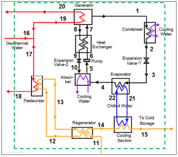
The food and beverage industry, with its extensive use of thermal processes such as pasteurization, presents significant potential for energy recovery. Pasteurization, a method of heat treatment used to kill harmful bacteria and extend the shelf life of products, often generates substantial amounts of waste heat. This waste heat can be harnessed and converted into electricity, offering the food and beverage sector a sustainable way to reduce energy consumption, lower operational costs, and contribute to environmental conservation.
In this section, we will explore how the heat from pasteurization processes can be used for electricity generation, the technologies involved, and the potential benefits and challenges of such systems.
1. The Pasteurization Process and Its Energy Demand
Pasteurization is a thermal process commonly used in the food and beverage industry, particularly for products such as milk, fruit juices, beer, canned foods, and sauces. The process typically involves heating a product to a specific temperature for a set period and then cooling it rapidly to eliminate pathogens and extend shelf life without compromising the product’s quality.
This process, while essential, is energy-intensive. Heat exchangers and pasteurization systems use steam or hot water to raise the temperature of the product. After the pasteurization step, large quantities of heat are often released into the environment, typically through cooling systems. This excess heat represents an untapped resource that can be recovered and utilized for electricity generation.
2. Waste Heat Recovery from Pasteurization
Waste heat recovery from pasteurization involves capturing the thermal energy released during the process and converting it into useful electricity. There are several technologies and systems that can be employed to recover this energy:
a. Organic Rankine Cycle (ORC)
One of the most commonly used technologies for converting waste heat into electricity is the Organic Rankine Cycle (ORC). ORC systems work similarly to steam turbines but use organic fluids with a lower boiling point than water, making them suitable for recovering lower-temperature heat (such as the heat from pasteurization processes).
In an ORC system, the waste heat from the pasteurization process is transferred to the working fluid, causing it to vaporize. The vapor then drives a turbine, which is connected to a generator to produce electricity. After passing through the turbine, the vapor is condensed back into a liquid and returned to the cycle.
ORC systems are particularly well-suited for food and beverage pasteurization, as they can efficiently generate electricity from the moderate temperatures typically found in the heat recovery process. These systems are also scalable and can be adjusted to meet the specific energy recovery needs of different-sized facilities.
b. Kalina Cycle
The Kalina cycle is a similar process to the ORC but uses a mixture of water and ammonia as the working fluid. The advantage of the Kalina cycle is that the fluid mixture can be adjusted to optimize the thermodynamic efficiency for specific temperature ranges, such as those found in the waste heat generated from pasteurization. By using a mixture of fluids with different boiling points, the Kalina cycle can achieve higher efficiency at lower temperatures, making it another viable option for generating electricity from pasteurization heat.
c. Absorption Chillers and Combined Heat and Power (CHP) Systems
In addition to electricity generation, some food and beverage companies use the waste heat from pasteurization to drive absorption chillers. These systems use waste heat to provide cooling, which is an essential function in the food industry. When coupled with CHP (Combined Heat and Power) systems, these solutions allow both electricity and thermal energy to be recovered from the waste heat, maximizing the overall energy efficiency.
In a CHP system, a generator powered by a gas or steam turbine produces electricity. At the same time, the waste heat from the turbine is recovered and can be used for heating or cooling applications. By using waste heat from pasteurization in conjunction with CHP systems, facilities can generate both the electricity needed to power operations and the thermal energy required for other processes, creating a more energy-efficient and cost-effective operation.
3. Benefits of Waste Heat Recovery from Pasteurization
The implementation of waste heat recovery systems in food and beverage pasteurization can bring several key benefits:
a. Reduced Energy Consumption
By capturing and reusing waste heat, food and beverage facilities can reduce their reliance on external sources of energy, such as electricity or natural gas. This not only leads to lower utility bills but also helps companies better manage energy resources, contributing to long-term cost savings.
b. Lower Environmental Impact
The food and beverage sector is under increasing pressure to reduce its carbon footprint. By recovering and reusing waste heat for electricity generation, companies can significantly reduce their overall greenhouse gas emissions. This reduction in carbon emissions can help companies meet sustainability goals and regulatory requirements while improving their environmental performance.
c. Enhanced Energy Efficiency
The integration of waste heat recovery systems can greatly improve the overall energy efficiency of a facility. By utilizing the heat that would otherwise be wasted, companies can ensure that they are making the most of the energy consumed during pasteurization. This not only lowers operating costs but also enhances the competitiveness of businesses that are able to operate more efficiently.
d. Increased Reliability and Resilience
The ability to generate electricity from waste heat provides facilities with a more stable and resilient energy supply. This can be particularly valuable for food and beverage companies that operate in regions with unreliable electricity grids or face intermittent power shortages. By producing their own electricity, companies can reduce the risk of production downtime due to power disruptions.
e. Compliance with Sustainability Regulations
As governments around the world implement stricter environmental regulations, the pressure on food and beverage companies to reduce waste and carbon emissions has intensified. Waste heat recovery systems can help companies comply with these regulations by demonstrating a commitment to energy efficiency and sustainability. Additionally, these systems may make companies eligible for tax incentives, subsidies, or other benefits associated with energy efficiency improvements.
4. Challenges and Considerations
While the benefits of waste heat recovery from pasteurization are significant, there are also some challenges and considerations to keep in mind when implementing these systems:
a. Initial Capital Investment
The installation of waste heat recovery systems, particularly ORC and Kalina cycle systems, can require a significant upfront investment. These systems can be expensive to install, and the payback period can vary depending on the scale of the facility, the amount of waste heat available, and the energy prices in the region. However, the long-term savings on energy costs and potential environmental benefits often outweigh the initial investment.
b. Maintenance and Operational Costs
Like any advanced technological system, waste heat recovery systems require regular maintenance and oversight to ensure optimal performance. Proper training and skilled personnel are needed to operate and maintain these systems. Additionally, there may be operational costs related to the management of waste heat recovery equipment, including the cost of parts and occasional system upgrades.
c. Space and Infrastructure Requirements
Integrating waste heat recovery systems into existing pasteurization facilities may require space and infrastructure adjustments. For example, ORC and Kalina cycle systems require dedicated areas for turbines, generators, and heat exchangers. In some cases, retrofitting existing facilities to accommodate waste heat recovery systems can be complex and costly, especially if the facility was not initially designed with such systems in mind.
d. Variability of Waste Heat
The amount of waste heat available from pasteurization processes can vary depending on the production schedule, the type of product being pasteurized, and the specific equipment used. This variability must be accounted for when designing and sizing waste heat recovery systems. In some cases, excess heat may need to be stored or managed to ensure that the recovery system can operate efficiently over time.
5. Conclusion: Harnessing Heat for a Sustainable Future
The potential for generating electricity from the waste heat produced during food and beverage pasteurization is a promising solution for improving energy efficiency and reducing environmental impact in the industry. By implementing advanced waste heat recovery systems, such as ORC or Kalina cycles, food and beverage companies can reduce their reliance on external energy sources, lower their carbon emissions, and improve their bottom line.
While challenges such as initial investment costs and space requirements exist, the long-term benefits—ranging from reduced energy consumption to improved sustainability—make waste heat recovery a worthwhile consideration for companies seeking to enhance their operational efficiency and environmental performance.
As technology continues to evolve and governments place greater emphasis on sustainability, the adoption of waste heat recovery in food and beverage pasteurization will likely become more widespread, helping the industry move toward a more energy-efficient and eco-friendly future.
6. Future Trends in Waste Heat Recovery from Pasteurization
As the food and beverage industry continues to focus on sustainability, energy efficiency, and cost reduction, the future of waste heat recovery from pasteurization is bright. Advancements in technology, increasing environmental regulations, and the drive for better resource utilization will further accelerate the adoption of waste heat recovery systems. In this section, we explore the emerging trends and innovations that could shape the future of waste heat recovery in the food and beverage sector.
a. Integration of Digitalization and IoT (Internet of Things)
The increasing adoption of digital technologies, such as Internet of Things (IoT) sensors and real-time monitoring systems, will enhance the efficiency and reliability of waste heat recovery systems in food and beverage pasteurization. By integrating sensors into heat exchangers, turbines, and other components of waste heat recovery systems, companies can collect data on performance, temperature fluctuations, pressure levels, and energy output.
Real-time data analysis allows operators to monitor system performance, detect inefficiencies or malfunctions, and take corrective actions before issues escalate. This predictive maintenance capability can extend the lifespan of waste heat recovery equipment and reduce downtime, ensuring that the systems continue to operate at peak efficiency. Additionally, IoT integration can help optimize the recovery process by adjusting operational parameters based on real-time data, further improving energy recovery and electricity generation.
b. Advanced Heat Recovery Materials
Advances in materials science are expected to lead to the development of more efficient and durable heat exchange materials, which could significantly enhance the effectiveness of waste heat recovery systems. Research into advanced materials such as nanomaterials, high-performance alloys, and ceramics will result in heat exchangers that can operate at higher temperatures and maintain better thermal conductivity.
Nanotechnology, for instance, could lead to heat exchangers that offer greater surface area for heat transfer, enabling more efficient heat capture from the pasteurization process. These innovations would make it possible to recover heat from a wider range of temperatures and further optimize electricity generation.
Furthermore, new materials with enhanced corrosion resistance will ensure the longevity of waste heat recovery systems, especially in food and beverage facilities where hygienic conditions are critical. The improved durability of heat recovery systems will lower maintenance costs and increase the return on investment for companies.
c. Integration with Renewable Energy Systems
The future of waste heat recovery in the food and beverage industry could see a stronger integration with renewable energy systems such as solar, wind, and biomass. By combining waste heat recovery technologies with renewable energy sources, food and beverage companies can create hybrid systems that enhance energy efficiency and sustainability.
For example, solar thermal collectors could be used to pre-heat water or air, which is then further heated by the waste heat from pasteurization processes. Wind or biomass energy could also be integrated into waste heat recovery systems to supplement electricity production. Hybrid systems would provide greater energy flexibility, improve resilience to power disruptions, and help companies meet renewable energy targets set by governments or industry standards.
These combined systems are particularly well-suited for large food processing facilities, where consistent energy demands can be met by both renewable sources and recovered heat, ensuring that operations continue smoothly even in the face of fluctuating energy availability.
d. Energy Storage Solutions
The integration of energy storage systems, such as thermal storage or battery storage, into waste heat recovery systems could greatly enhance their effectiveness. Thermal energy storage systems capture excess heat generated during the pasteurization process and store it for later use, particularly during times when electricity demand is low or when waste heat recovery is not producing enough energy.
For instance, molten salt storage systems, commonly used in solar thermal power plants, could store heat for use in electricity generation when demand peaks. In parallel, batteries can store excess electricity generated by waste heat recovery and provide backup power when needed. Combining these storage solutions with waste heat recovery could help smooth out fluctuations in energy generation, ensuring a stable and continuous power supply.
This integration could be particularly useful in areas with intermittent electricity supply, helping food and beverage plants remain operational without relying on external grids or backup generators.
e. Adoption of Modular Waste Heat Recovery Systems
As mentioned earlier, modular waste heat recovery systems allow companies to start small and scale up as needed. This trend toward modularity is expected to continue, particularly as smaller food and beverage producers seek affordable solutions for energy recovery. These systems can be customized based on the size of the facility, the type of products being processed, and the amount of waste heat generated.
Modular systems can be easily integrated into existing infrastructure, providing a more accessible option for smaller businesses or those with limited capital for large-scale installations. Additionally, modularity allows for the gradual expansion of waste heat recovery capabilities as the company’s needs grow, making it easier to adapt to changing energy demands and production schedules.
f. Enhanced Sustainability and Circular Economy
The increasing emphasis on sustainability and the circular economy will likely drive greater adoption of waste heat recovery in the food and beverage sector. As more companies seek to reduce their environmental impact, there will be a growing focus on minimizing waste and maximizing resource use. Waste heat recovery systems are a natural fit for this agenda, as they capture energy that would otherwise be lost and repurpose it for productive use.
In addition to generating electricity, the recovered heat from pasteurization could be used for other processes within the facility, such as drying, heating, or sterilizing equipment, reducing the need for additional energy inputs. This circular approach to energy use within food and beverage operations will help companies achieve zero waste or closed-loop energy systems, further contributing to their sustainability goals.
g. Policy Support and Regulatory Incentives
Governments around the world are implementing more stringent environmental regulations and carbon reduction goals, which will likely create more incentives for food and beverage companies to adopt waste heat recovery systems. These policies may include tax credits, grants, or subsidies for energy efficiency projects, making waste heat recovery more financially attractive.
In addition to regulatory incentives, many countries are introducing carbon pricing mechanisms, which place a financial cost on carbon emissions. By implementing waste heat recovery systems, food and beverage companies can reduce their carbon footprint and avoid potential carbon tax penalties. This will be a strong motivator for the industry to adopt waste heat recovery technologies as part of their broader sustainability strategies.
7. Conclusion: A Future of Efficiency and Sustainability
As the food and beverage industry continues to focus on sustainability, energy efficiency, and cost reduction, waste heat recovery from pasteurization will play an increasingly important role in shaping a more sustainable future. By adopting advanced technologies such as ORC and Kalina cycle systems, integrating digital solutions, and leveraging renewable energy sources, the industry can make significant strides toward reducing its environmental impact while improving its operational efficiency.
The growing trend of hybrid energy systems, combined with energy storage solutions, will further enhance the viability of waste heat recovery, ensuring that food and beverage companies can optimize energy use throughout the production process. In parallel, advances in materials science and digitalization will improve system performance, reduce costs, and make waste heat recovery systems more accessible to companies of all sizes.
With increasing support from policymakers, the potential for waste heat recovery in food and beverage pasteurization is vast. The industry is poised to benefit from this emerging technology, which will not only provide cost savings and improve energy efficiency but also contribute to the global push for decarbonization and sustainable resource management.
8. Case Studies of Successful Waste Heat Recovery in Food and Beverage Pasteurization
Real-world examples of waste heat recovery systems in the food and beverage industry can provide valuable insights into the practical benefits and challenges associated with these technologies. In this section, we will explore a few case studies where companies have successfully implemented waste heat recovery systems for pasteurization processes, highlighting the results achieved and the lessons learned.
a. Case Study 1: Dairy Plant in the Netherlands
A dairy processing facility in the Netherlands implemented an Organic Rankine Cycle (ORC) system to recover waste heat from its pasteurization process. The facility processes large volumes of milk, which requires significant energy for pasteurization. The waste heat generated during the cooling of pasteurized milk was captured and used to drive an ORC turbine to generate electricity.
The installation of the ORC system allowed the dairy plant to generate approximately 1.5 MW of electricity, which was sufficient to meet about 20% of the facility’s total electricity needs. This reduced the plant’s reliance on external power and lowered its annual energy costs by around 15%. The system also contributed to a reduction in CO2 emissions by offsetting the need for grid electricity, which would otherwise have been generated from fossil fuels.
One of the key takeaways from this case study was the importance of correctly sizing the ORC system to match the heat recovery potential of the pasteurization process. Additionally, the plant benefited from government incentives for energy efficiency improvements, which helped reduce the initial capital investment required for the system.
b. Case Study 2: Beverage Company in the United States
A large beverage manufacturer in the United States adopted a Kalina cycle-based waste heat recovery system to capture the waste heat from its pasteurization processes for bottled beverages. The company was looking for ways to increase its sustainability efforts, reduce operational costs, and address rising energy prices. The system was designed to recover heat from the pasteurization step, which had traditionally been vented into the atmosphere or used for low-value thermal applications.
The Kalina cycle system was able to generate up to 2 MW of electricity, which helped the company cut down its electricity bills by approximately 18%. In addition to the direct cost savings, the company reduced its carbon footprint by approximately 25%, as the waste heat recovery system displaced electricity that would otherwise have been sourced from fossil fuels. The company also noticed an increase in the reliability of its operations, as the waste heat recovery system helped stabilize energy supply during peak demand periods.
One challenge faced during implementation was the complexity of integrating the Kalina cycle system with the existing infrastructure, as it required retrofitting the facility’s heat exchangers and piping. However, the long-term benefits in terms of cost savings, energy security, and sustainability made the investment worthwhile.
c. Case Study 3: Beer Brewing Facility in Germany
A beer brewery in Germany undertook a project to recover waste heat from its pasteurization process to power a combined heat and power (CHP) system. The brewery was already using traditional boilers for heating and energy generation but sought to improve its energy efficiency and reduce operational costs.
The brewery installed a CHP system that used the waste heat from pasteurization to drive a gas turbine and generate electricity. The system not only produced electricity for the facility but also supplied heat for the brewing process, making the brewery more self-sufficient. The waste heat recovery system provided around 30% of the brewery’s total electricity needs, resulting in significant cost savings.
In addition to the financial savings, the brewery was able to reduce its carbon emissions by approximately 20%, contributing to its sustainability objectives. The brewery also integrated an energy storage system, allowing it to store excess electricity generated during periods of low demand, which could be used during peak periods or for backup power.
The brewery faced challenges in maintaining the efficiency of the system, particularly when it came to monitoring and optimizing the performance of the gas turbine. However, with the help of advanced monitoring and control systems, the brewery was able to keep the system operating at peak performance.
d. Case Study 4: Fruit Juice Manufacturer in Brazil
A fruit juice manufacturer in Brazil implemented a waste heat recovery system based on an ORC turbine to harness the thermal energy from its pasteurization process. Brazil’s growing energy demand and high energy costs were key drivers behind the company’s decision to invest in energy efficiency technologies.
The ORC system recovered heat from the pasteurization and sterilization stages of the juice production process. The electricity generated was used to power the facility’s cooling systems, pumps, and other equipment, reducing the company’s dependence on the local power grid. The waste heat recovery system provided about 1 MW of electricity, covering approximately 15% of the facility’s energy needs.
The company also benefited from reduced water consumption, as the heat recovery system allowed for better management of cooling processes. By using the recovered heat for pre-heating water, the company lowered the overall energy required for the pasteurization process. This project contributed to a reduction in CO2 emissions, helping the company meet its environmental targets.
One challenge faced during implementation was the availability of skilled labor to manage the complex heat recovery and ORC systems. However, the company overcame this by providing training for its engineering team and establishing a preventive maintenance schedule to ensure the system operated efficiently.
9. Key Takeaways from Case Studies
These case studies highlight several important lessons for food and beverage companies considering the adoption of waste heat recovery systems for pasteurization:
- Proper System Sizing: Properly sizing the waste heat recovery system based on the heat output from the pasteurization process is critical to maximizing energy recovery and minimizing costs. Overestimating or underestimating heat recovery potential can lead to inefficient system performance.
- Integration Challenges: Retrofitting existing facilities with waste heat recovery systems may require significant infrastructure changes, such as modifying piping, heat exchangers, or cooling systems. While this can be a challenge, careful planning and expert consultation can ensure a smooth integration process.
- Financial Incentives: Government subsidies, tax incentives, and grants for energy efficiency projects can significantly reduce the upfront capital investment required for waste heat recovery systems. Companies should explore available incentives to help offset installation costs.
- Operational Benefits: Beyond cost savings, waste heat recovery systems provide operational benefits such as increased energy reliability, improved operational efficiency, and reduced carbon emissions. These advantages contribute to both financial performance and sustainability goals.
- Ongoing Maintenance: Waste heat recovery systems require regular maintenance to ensure optimal performance. Preventive maintenance and real-time monitoring of system performance can help detect issues early and extend the life of the equipment.
- Hybrid Systems for Enhanced Efficiency: Combining waste heat recovery with other renewable energy sources, such as solar or biomass, can enhance system efficiency and reliability, providing a more resilient energy supply for food and beverage operations.
10. Conclusion: Capitalizing on Waste Heat Recovery for Long-Term Success
Waste heat recovery in the food and beverage industry, particularly in pasteurization processes, is a proven strategy for improving energy efficiency, reducing operational costs, and enhancing sustainability. As demonstrated by the case studies, the integration of advanced technologies such as ORC, Kalina cycles, and CHP systems can offer substantial benefits, from cost savings to lower carbon footprints.
While challenges such as initial investment and system integration exist, the long-term financial, environmental, and operational benefits often outweigh the costs. By adopting waste heat recovery solutions, companies can not only improve their energy efficiency and reduce costs but also contribute to a more sustainable and eco-friendly future.
As the industry continues to prioritize sustainability and energy efficiency, the adoption of waste heat recovery systems will likely become a common practice, helping food and beverage companies achieve their environmental and operational goals while remaining competitive in an increasingly energy-conscious market.
1. Introduction to Generating Electricity from Industrial Compressors
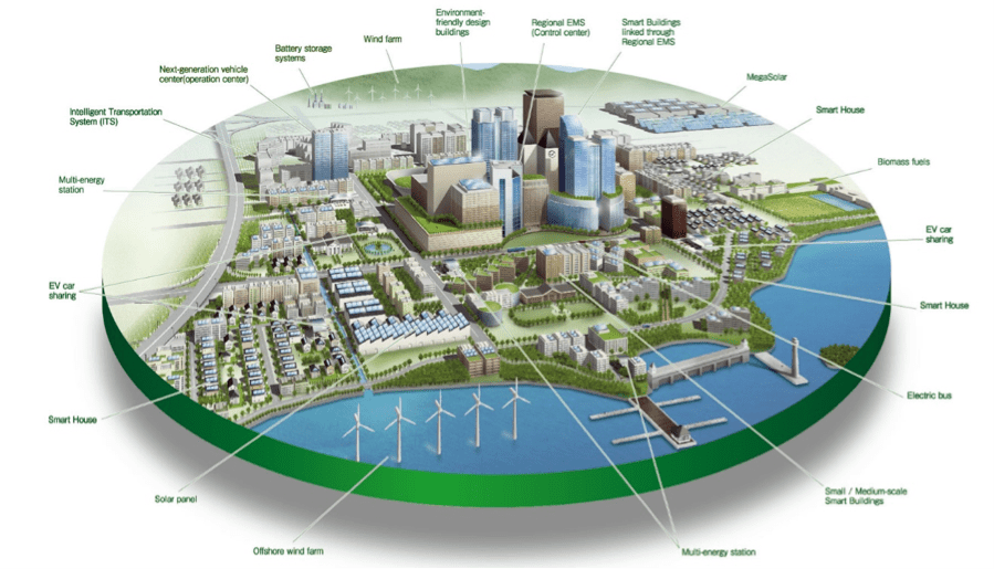
Industrial compressors are used extensively in various sectors, such as manufacturing, refrigeration, petrochemicals, and air conditioning, to compress air or gases for a wide range of applications. These compressors, especially when operating continuously, generate a significant amount of waste heat during the compression process. This heat is often vented into the environment, contributing to inefficiency and wasted energy. However, it is possible to capture this waste heat and use it to generate electricity, creating a more sustainable and cost-effective energy solution for industrial operations.
Generating electricity from the waste heat of industrial compressors involves utilizing the thermal energy produced during the compression cycle and converting it into usable power. This process can significantly reduce operational energy costs, lower carbon emissions, and improve the overall energy efficiency of industrial plants.
2. How Heat from Industrial Compressors Can Be Used to Generate Electricity
Heat recovery from industrial compressors typically follows a few key steps, utilizing either thermodynamic cycles or organic Rankine cycles (ORC), depending on the temperature range and characteristics of the waste heat. Here’s a breakdown of the process:
a. Heat Capture
Industrial compressors generate heat primarily through the compression of gases, which leads to a rise in temperature. The heat is usually carried away by cooling systems such as air or water cooling. By capturing this waste heat through heat exchangers or cooling loops, it can be directed to a heat recovery system.
In some cases, the heat can be captured directly from the compressor’s exhaust gases or coolant, while in other instances, a heat recovery loop is installed to extract thermal energy from the compressor’s surrounding environment.
b. Conversion to Mechanical Energy
Once the heat is captured, it needs to be converted into mechanical energy. This is typically achieved through a heat engine or thermodynamic cycle, such as an Organic Rankine Cycle (ORC) or Stirling engine.
- Organic Rankine Cycle (ORC): ORC systems are well-suited for low-to-medium temperature waste heat recovery. In ORC, the captured heat is used to heat a working fluid (usually organic fluids like refrigerants or hydrocarbons) that has a lower boiling point than water. The heated fluid vaporizes and expands through a turbine, which drives a generator to produce electricity. The ORC system is designed to operate efficiently at relatively low temperatures, making it an ideal solution for recovering heat from industrial compressors.
- Stirling Engines: In some cases, industrial heat recovery systems may utilize Stirling engines, which operate by heating a working fluid inside a sealed system and using the pressure difference to generate mechanical motion that drives a generator. Stirling engines can work effectively in temperature ranges similar to ORC systems and have the advantage of being relatively quiet and highly efficient at converting low-grade heat into power.
c. Electricity Generation
Once mechanical energy is generated from the heat, it is converted into electrical energy via a generator. The electricity generated can be used on-site to power the compressors or other equipment within the facility, reducing the need for purchased electricity from the grid. Excess electricity can also be stored in batteries or fed back into the grid, generating additional revenue for the company.
d. Heat Rejection
After the working fluid has passed through the turbine or engine, it is typically cooled and condensed before being recirculated through the system. The residual heat can then be rejected via cooling towers, heat exchangers, or other means, depending on the system’s design.
3. Applications of Waste Heat Recovery from Industrial Compressors
Waste heat recovery from compressors can be applied across a range of industries, each with its specific needs and challenges. Here are some examples of industrial sectors that can benefit from heat recovery systems for electricity generation:
a. Manufacturing Industry
Manufacturing plants that use industrial compressors in processes like metal forming, plastic molding, and air-powered tools often face high energy demands and significant waste heat production. Recovering heat from compressors and converting it to electricity can help power other equipment within the plant or offset electricity demand. This contributes to lowering overall operational costs and improving the energy efficiency of the plant.
b. Refrigeration and HVAC
The refrigeration and HVAC industries rely heavily on compressors to regulate temperature and airflow in cooling systems. Compressors in refrigeration systems generate a significant amount of waste heat. By installing waste heat recovery systems, these industries can harness thermal energy from compressors to power refrigeration cycles, defrosting systems, or even produce additional electricity to offset their energy consumption.
c. Petrochemical and Chemical Processing
The petrochemical and chemical processing industries often use large industrial compressors for various applications, including air separation, gas compression, and fluid transfer. These compressors generate large amounts of waste heat, which can be recovered and used to generate electricity, reducing reliance on grid power and lowering operational costs.
d. Oil and Gas Industry
In oil and gas operations, compressors are frequently used to transport gases, control pressure, and perform other essential functions. These compressors operate under high pressure and generate significant heat. Waste heat recovery systems can convert this heat into electricity, improving energy efficiency and reducing the environmental impact of these operations.
e. Mining Industry
The mining industry also uses industrial compressors for operations such as ventilation, mineral processing, and equipment cooling. By implementing waste heat recovery systems, mining operations can reduce energy consumption, lower operational costs, and contribute to more sustainable practices.
4. Benefits of Generating Electricity from Waste Heat in Compressors
There are numerous advantages to recovering waste heat from industrial compressors to generate electricity. Some of the most notable benefits include:
a. Cost Savings
The most immediate benefit of waste heat recovery systems is the reduction in energy costs. By generating electricity on-site, industrial plants can offset their electricity consumption from the grid, leading to lower energy bills. This is particularly advantageous in industries that rely heavily on compressors, as these devices often run continuously, making the potential for cost savings significant.
b. Increased Energy Efficiency
Generating electricity from waste heat improves overall energy efficiency in industrial processes. Instead of allowing valuable thermal energy to be vented into the atmosphere, companies can capture and repurpose it for productive use. This contributes to a more sustainable operation by reducing waste and increasing the effective use of energy resources.
c. Environmental Benefits
Recovering waste heat reduces the overall carbon footprint of industrial plants. By generating electricity from waste heat, the reliance on grid power, often generated by burning fossil fuels, is reduced. This leads to a decrease in CO2 emissions, helping companies meet environmental regulations and sustainability targets.
d. Enhanced System Reliability
Waste heat recovery systems can also enhance the reliability of industrial operations. By generating electricity on-site, companies are less reliant on external power sources, reducing the risk of production downtime due to grid instability or outages. Additionally, many systems can be designed with energy storage capabilities, ensuring a steady and reliable supply of power.
e. Return on Investment (ROI)
While the initial capital investment for heat recovery systems can be significant, the long-term return on investment is often substantial. Energy savings, reduced operational costs, and potential revenue from selling excess electricity to the grid can provide a positive ROI over time. Additionally, government incentives and tax credits for energy efficiency projects may help offset initial costs.
5. Challenges and Considerations in Implementing Heat Recovery Systems
While the benefits of waste heat recovery are clear, there are several challenges and considerations to keep in mind when implementing a system:
a. Initial Capital Investment
The upfront costs of installing a heat recovery system can be significant, especially for larger industrial compressors. However, the long-term energy savings and ROI often justify the initial investment. Companies may also be eligible for government grants, subsidies, or tax incentives to help offset the costs of energy efficiency projects.
b. System Integration
Integrating a waste heat recovery system with existing compressor systems and industrial infrastructure can be complex. Retrofits may require changes to piping, cooling systems, or control mechanisms. Companies should work with experienced engineers and system integrators to ensure smooth implementation and compatibility.
c. Maintenance and Operational Complexity
Waste heat recovery systems require regular maintenance to ensure optimal performance. Components such as turbines, heat exchangers, and heat engines may require periodic servicing, which can add to operational costs. Additionally, operators may need specialized training to handle the complexities of the recovery system.
d. Temperature Range Limitations
Not all compressors produce waste heat at the ideal temperature range for efficient conversion to electricity. Low-temperature waste heat may not be suitable for certain types of heat recovery systems, such as Rankine or Stirling engines, without modifications. The design and selection of the appropriate recovery system depend on the temperature of the waste heat and the specific requirements of the operation.
6. Conclusion: The Future of Electricity Generation from Compressor Heat
Generating electricity from waste heat produced by industrial compressors offers significant opportunities for energy savings, increased efficiency, and environmental benefits. As industrial operations increasingly focus on reducing their carbon footprints and improving sustainability, waste heat recovery systems will become an essential component of energy management strategies.
By utilizing advanced technologies such as ORC systems, Stirling engines, and integrated energy storage solutions, companies can tap into the full potential of their waste heat, reducing reliance on external electricity sources and contributing to a greener, more efficient industrial landscape.
7. Future Trends and Innovations in Waste Heat Recovery from Compressors
As industries strive to meet rising energy demands while adhering to environmental regulations and sustainability goals, innovations in waste heat recovery technologies will continue to evolve. The future of generating electricity from industrial compressor waste heat holds great potential as emerging technologies offer greater efficiency, lower costs, and wider applicability. Here are some of the key trends and innovations likely to shape the future of waste heat recovery from compressors.
a. Advanced Organic Rankine Cycle (ORC) Systems
The ORC technology, already widely used for waste heat recovery, is expected to see further advancements in the coming years. New working fluids with better thermodynamic properties are being developed to increase the efficiency of ORC systems. These fluids can operate effectively at both lower and higher temperatures, making ORC systems more versatile and suitable for a broader range of industrial applications, including heat recovery from compressors.
Advances in heat exchanger design and turbine efficiency will also improve the overall performance of ORC systems. These innovations will make ORC technology more cost-effective, enabling a faster return on investment and reducing energy costs for industries that rely on large-scale compressor systems.
b. Hybrid Systems for Optimized Energy Recovery
Hybrid systems, which combine multiple energy recovery methods, are becoming increasingly popular. For example, combining ORC with other technologies such as absorption chillers or heat pumps can optimize the recovery of thermal energy from compressors while simultaneously providing cooling. This can be particularly beneficial in industries where compressors not only generate waste heat but also require cooling for machinery or other processes.
By integrating waste heat recovery with both electricity and cooling generation, these hybrid systems offer a more efficient and flexible solution to meet the diverse energy needs of industrial facilities. Furthermore, they help companies reduce energy costs and enhance system resilience, especially in environments with fluctuating energy demands.
c. Internet of Things (IoT) and Smart Monitoring
The integration of the Internet of Things (IoT) in waste heat recovery systems is revolutionizing the way industries monitor and manage energy consumption. IoT-enabled sensors and smart monitoring systems can provide real-time data on the performance of compressors, heat recovery units, and the overall efficiency of the energy recovery process.
Using data analytics and machine learning, companies can identify areas for optimization, predict potential system failures, and fine-tune operations to ensure maximum efficiency. These smart systems not only improve the performance of the heat recovery process but also extend the lifespan of equipment by reducing wear and tear and ensuring maintenance is conducted at optimal intervals.
d. Use of Advanced Heat Exchangers
One of the key components of an efficient waste heat recovery system is the heat exchanger, which transfers thermal energy from the waste heat to the working fluid. Advances in heat exchanger technologies, including the use of nanomaterials and compact designs, will further improve heat transfer efficiency, making the systems more compact and effective.
New designs such as microchannel heat exchangers and enhanced surface area materials will increase the heat transfer rate, allowing for more efficient recovery of low-grade heat. This will be particularly beneficial in environments where space is limited or where waste heat is at lower temperatures, such as industrial compressors.
e. Sustainable and Green Refrigerants
In the context of compressor systems, refrigerants play a vital role in the overall efficiency of heat recovery. As the regulatory pressure on global warming potential (GWP) of refrigerants increases, there is a growing demand for natural refrigerants and low-GWP alternatives that are both effective and environmentally friendly. These sustainable refrigerants can improve the energy efficiency of compressors and heat recovery systems, providing a greener solution for industries looking to reduce their carbon footprint.
The development of more efficient refrigerants and technologies will enhance the feasibility of integrating waste heat recovery systems into existing compressor operations, making them more energy-efficient and environmentally friendly.
f. Thermoelectric Generators (TEGs) for Low-Grade Heat Recovery
Thermoelectric generators (TEGs) are solid-state devices that directly convert temperature differences into electrical voltage through the Seebeck effect. While TEGs are still relatively nascent compared to conventional waste heat recovery technologies like ORC, they hold significant potential for low-grade heat recovery.
In the future, the use of TEGs for capturing and converting waste heat from compressors may become more viable due to improvements in materials science, which could lead to more efficient thermoelectric materials. The key advantage of TEGs is that they can operate at lower temperature gradients, which makes them well-suited for recovering heat from compressors that produce relatively mild waste heat.
g. Energy Storage Integration
To further optimize energy recovery from industrial compressors, waste heat recovery systems can be paired with energy storage solutions. By integrating energy storage, such as batteries or thermal storage systems, excess electricity generated from waste heat can be stored and used during periods of high demand or when energy costs are higher.
Energy storage technologies, particularly in combination with renewable energy sources, will enable industries to better manage energy consumption, reduce peak load, and become more self-sufficient in their energy needs. By storing electricity generated from waste heat, companies can enhance operational flexibility and reduce reliance on grid electricity.
8. The Road to Widespread Adoption
While the benefits of generating electricity from waste heat in industrial compressors are clear, several factors must be addressed to drive widespread adoption:
a. Economic Feasibility
The economic viability of waste heat recovery systems largely depends on the upfront capital costs, the availability of government incentives, and the long-term return on investment. Although technologies like ORC and hybrid systems can be expensive to install, their ability to significantly reduce energy costs over time provides a compelling argument for many industrial operators.
Government policies, grants, and tax incentives aimed at encouraging energy efficiency will play a significant role in accelerating the adoption of waste heat recovery systems. As technology improves and the cost of equipment continues to decline, waste heat recovery will become a more accessible option for a wider range of industries.
b. Policy Support and Regulatory Frameworks
Government policies that promote sustainability and energy efficiency will encourage companies to invest in waste heat recovery systems. Some countries already have stringent energy efficiency regulations and emission reduction targets that incentivize the adoption of heat recovery technologies. Policy support, such as tax credits, financial incentives, and performance-based programs, will be crucial in helping businesses overcome the initial cost barrier and realize the long-term benefits of waste heat recovery.
c. Technological Advancements
As technology continues to evolve, the efficiency of heat recovery systems will improve, and new solutions will emerge. More efficient and lower-cost systems, along with the integration of advanced control systems, will make waste heat recovery from compressors increasingly attractive to industries. As the technology matures, new methods of capturing and utilizing waste heat will emerge, enabling even greater reductions in energy consumption and carbon emissions.
d. Awareness and Education
Many industrial facilities are not fully aware of the potential savings and environmental benefits associated with waste heat recovery systems. Educating industry stakeholders on the importance of energy efficiency and the role of waste heat recovery can help promote greater adoption. As awareness grows, companies will be more inclined to invest in these technologies, especially if they see the clear benefits in terms of cost savings, energy security, and sustainability.
9. Conclusion: A Sustainable and Efficient Future
Generating electricity from industrial compressor waste heat represents a significant opportunity for companies to improve energy efficiency, reduce costs, and meet sustainability goals. As heat recovery technologies continue to evolve and become more efficient, the widespread adoption of these systems will play an essential role in transforming industries toward more sustainable energy practices.
By capturing and converting waste heat into usable electricity, industrial operations can not only lower their energy bills but also contribute to reducing greenhouse gas emissions and promoting a circular economy. With ongoing innovations and the right mix of policies and economic incentives, waste heat recovery from compressors has the potential to become a key component of future energy solutions in industries across the globe.
10. Case Studies of Successful Waste Heat Recovery from Compressors
Real-world examples of companies successfully utilizing waste heat recovery systems from compressors can provide valuable insights into the practical benefits and challenges of these technologies. Here are some case studies from various industries that highlight the effectiveness of generating electricity from industrial compressor waste heat:
a. Case Study 1: Manufacturing Plant in the Automotive Industry
A major automotive manufacturer in Germany implemented a waste heat recovery system to capture heat generated by its air compressors used in assembly lines and robotic systems. The captured heat was used to power a turbine-based ORC system that produced electricity, which was then fed back into the plant’s grid.
Over the course of two years, the plant saved approximately 15% on its overall energy bill, primarily by reducing its reliance on electricity from the national grid. The installation of the ORC system also contributed to a significant reduction in CO2 emissions, helping the plant meet its sustainability goals.
One key challenge for the automotive plant was the need to retroactively install the heat recovery system without disrupting ongoing production. However, through careful planning and phased installation, the company was able to integrate the system successfully, making use of existing infrastructure to maximize the efficiency of the project.
b. Case Study 2: Refrigeration Company in North America
A large refrigeration facility in the United States, which services supermarkets and cold storage warehouses, decided to recover waste heat from its industrial compressors used for refrigeration cycles. The plant used a combination of waste heat capture and an ORC system to generate electricity that powered the facility’s lighting, heating, and some refrigeration operations.
The decision to implement waste heat recovery was driven by the rising cost of electricity and the need to improve the sustainability of the refrigeration process. By capturing waste heat from the compressors, the plant was able to cut its electricity consumption by approximately 20%, while reducing its greenhouse gas emissions by over 500 tons per year.
One of the main lessons learned was the importance of system integration. The facility had to ensure that the ORC system was properly integrated into the existing refrigeration infrastructure to avoid operational disruptions. Additionally, periodic maintenance and monitoring of the system allowed the company to continuously optimize performance and prevent any potential downtime.
c. Case Study 3: Chemical Processing Facility in the Middle East
A chemical processing facility in the Middle East, where compressors were used for gas compression and chemical production, faced high energy costs due to the constant operation of its large-scale compressor systems. To mitigate these costs, the facility implemented a combined heat and power (CHP) system that utilized the waste heat from the compressors.
This CHP system not only generated electricity but also provided heating for the chemical processing units, reducing the plant’s reliance on external sources for both power and thermal energy. The electricity generated from waste heat was enough to cover about 30% of the facility’s total energy needs.
The major challenge faced by the plant was the high temperature of the waste heat from the compressors, which exceeded the optimal temperature range for traditional ORC systems. To overcome this, the facility worked with engineers to design a custom ORC system that could handle higher temperature gradients, ensuring maximum recovery efficiency.
d. Case Study 4: Oil and Gas Refinery in Brazil
In Brazil, an oil and gas refinery installed a waste heat recovery system that captured the heat produced by compressors used in the gas processing and separation units. The heat recovery system utilized a combination of ORC technology and thermal storage to generate electricity that powered auxiliary operations within the refinery.
This project was part of the refinery’s broader initiative to reduce energy consumption and carbon emissions as part of its commitment to environmental sustainability. The heat recovery system generated sufficient electricity to cover about 15% of the refinery’s overall energy demand, resulting in substantial cost savings.
While the project was a success in terms of energy efficiency, the refinery had to address challenges related to the corrosive nature of the gases involved in the heat recovery process. Special materials were used in the system’s construction to prevent damage and ensure the longevity of the equipment.
11. Overcoming Barriers to Waste Heat Recovery Implementation
Despite the clear benefits of waste heat recovery from compressors, many industries face barriers to widespread adoption. These challenges include financial, technical, and operational obstacles that must be addressed to make the implementation of waste heat recovery systems more attractive and feasible.
a. High Initial Capital Costs
One of the main barriers to adopting waste heat recovery technologies is the initial capital investment required for equipment installation and system integration. While the long-term savings can offset these costs, many companies hesitate to invest in these systems due to the high upfront expenditure.
To overcome this, companies can explore financing options such as energy performance contracts, where the cost of the system is paid back over time based on the energy savings it generates. Additionally, government subsidies, tax incentives, or grants for energy efficiency projects can help reduce the initial financial burden.
b. Lack of Expertise and Knowledge
The installation and operation of waste heat recovery systems require specialized knowledge and expertise in thermodynamics, system design, and integration. Many industrial facilities lack the internal expertise to manage the complexity of such systems, which can deter them from pursuing waste heat recovery solutions.
To address this, companies can partner with experienced energy consultants or engineers who specialize in heat recovery technologies. Ongoing training and support from system integrators and manufacturers can also help ensure that plant personnel are well-equipped to manage the system effectively.
c. System Integration Challenges
Integrating a waste heat recovery system into existing compressor infrastructure can be technically complex, especially in older facilities. Retrofitting systems to capture waste heat and convert it into electricity may require significant changes to piping, cooling systems, or control mechanisms, leading to operational disruptions and increased costs.
To mitigate this, companies should carefully assess their existing infrastructure and work with experienced integrators to design a system that fits seamlessly into their operations. Phased implementation, where the system is installed incrementally without disrupting production, can also help minimize downtime and reduce installation costs.
d. Ongoing Maintenance and Monitoring
Waste heat recovery systems, like any other industrial equipment, require regular maintenance to ensure optimal performance. The need for continuous monitoring, maintenance, and potential repairs can be a concern for companies, particularly those that operate large-scale compressor systems.
To address these concerns, companies can implement predictive maintenance strategies using IoT and data analytics. This allows for early detection of issues, minimizing the risk of system failure and ensuring that maintenance is conducted before problems escalate. Additionally, many modern systems are designed for ease of maintenance, with components that are durable and require minimal intervention.
12. The Role of Policy and Regulation in Promoting Waste Heat Recovery
Government policies and regulations play a critical role in driving the adoption of waste heat recovery systems across industries. Policies aimed at reducing carbon emissions, improving energy efficiency, and promoting sustainable industrial practices will be essential in encouraging more companies to implement waste heat recovery solutions.
a. Emission Reduction Targets
Many countries have set stringent carbon emission reduction targets as part of their commitments to international climate agreements. Waste heat recovery can help industries meet these targets by reducing their reliance on fossil fuels and lowering overall energy consumption. Governments may introduce stricter emissions regulations that compel companies to adopt energy-efficient technologies like waste heat recovery.
b. Financial Incentives and Subsidies
Governments can provide financial incentives, tax credits, and grants to offset the cost of implementing waste heat recovery systems. These incentives can significantly reduce the financial barrier and make these technologies more accessible to companies, particularly in energy-intensive industries like manufacturing, oil and gas, and chemicals.
c. Energy Efficiency Standards
In addition to emission reduction targets, governments are increasingly introducing energy efficiency standards that mandate the use of energy-efficient technologies in industrial operations. These regulations often encourage the adoption of waste heat recovery systems, either through direct mandates or by offering benefits to companies that adopt such technologies.
d. Industry-Specific Guidelines and Programs
Some industries, such as oil and gas or chemicals, may have specific guidelines and programs to support waste heat recovery. Industry associations, regulators, and utility companies often collaborate to create frameworks that facilitate the adoption of energy-efficient technologies. These programs might include technical support, shared best practices, and networking opportunities for companies looking to implement heat recovery solutions.
13. Conclusion: A Path Towards Sustainable Industrial Energy Management
Waste heat recovery from industrial compressors represents a crucial opportunity for companies to improve energy efficiency, reduce operational costs, and contribute to environmental sustainability. By capturing and converting the heat that would otherwise be wasted, industries can generate electricity, decrease their reliance on grid power, and lower their carbon emissions.
Although there are challenges to implementation, such as high initial costs, system integration complexities, and the need for specialized expertise, these barriers can be overcome with careful planning, technological advancements, and support from governments and industry experts. As waste heat recovery technologies continue to improve and become more affordable, their adoption will play an essential role in building a more sustainable and energy-efficient industrial landscape.
The future of waste heat recovery from compressors looks promising, with ongoing innovations in heat engine efficiency, hybrid systems, and smart monitoring ensuring that these systems will become even more effective and widely deployed in industries across the globe. By adopting waste heat recovery, industries can not only reduce energy consumption and operating costs but also contribute to a greener, more sustainable world.
Generating Electricity using Heat from Sawmill Operations
Sawmills, which process timber into lumber and other wood products, are energy-intensive operations. These facilities generate significant amounts of waste heat from various stages of the milling process, such as drying, sawing, and kiln operations. This heat, if properly captured and utilized, presents an opportunity to generate electricity and improve the overall energy efficiency of the sawmill. By harnessing this waste heat, sawmills can reduce their energy costs, improve their environmental sustainability, and contribute to a circular economy.
1. Waste Heat Sources in Sawmill Operations
Sawmills produce waste heat from several key processes, and each of these sources can potentially be tapped for electricity generation:
a. Kiln Drying
The drying process in sawmills typically involves the use of large kilns, which are heated by burning wood or other fuels to remove moisture from the lumber. During this process, a significant amount of heat is released into the environment as the air used to dry the wood is heated. This high-temperature exhaust air can be captured and used in a waste heat recovery system.
b. Sawing and Wood Processing
The mechanical processes of sawing, grinding, and cutting wood often generate frictional heat. While this heat is typically localized and not as high in temperature as that from kilns, it still represents a potential source of low-grade waste heat that can be recovered.
c. Biomass Combustion
Sawmills often burn biomass (such as wood chips, sawdust, and bark) to generate heat for various processes, including drying. While some of this heat is already utilized, excess heat generated during combustion can be captured and converted into electricity.
d. Heat from Boilers and Engines
Sawmills that use steam boilers or engines to generate mechanical or thermal power often release excess heat from these systems. This heat can also be captured and used to generate electricity.
2. Technologies for Capturing and Converting Waste Heat into Electricity
To convert waste heat from sawmill operations into electricity, several technologies can be used. The choice of technology depends on factors such as the temperature and quantity of the available waste heat, as well as the specific energy needs of the sawmill.
a. Organic Rankine Cycle (ORC)
The Organic Rankine Cycle (ORC) is one of the most popular technologies for recovering waste heat and converting it into electricity. ORC systems work similarly to traditional steam turbines, but they use organic fluids with lower boiling points, which makes them ideal for lower temperature heat sources.
In sawmills, ORC systems can be used to recover waste heat from the exhaust gases of kilns, boilers, and combustion processes. The organic fluid absorbs the heat, vaporizes, and drives a turbine to generate electricity. The cooled vapor is then condensed and recirculated in a closed-loop system, allowing for continuous operation.
The advantage of ORC systems is their ability to efficiently operate with low-temperature heat sources (typically between 80°C to 300°C), making them well-suited for the waste heat available in sawmill operations. The ORC system can generate electricity while reducing the reliance on external energy sources.
b. Combined Heat and Power (CHP) Systems
Combined Heat and Power (CHP) systems, also known as cogeneration systems, provide both electricity and useful heat from the same energy source. In sawmills, CHP systems can capture waste heat from kilns, boilers, and biomass combustion, using it to generate both electricity and thermal energy for use in the mill.
In CHP systems, the waste heat is typically used to produce steam, which then drives a turbine to generate electricity. The exhaust steam is then recovered for use in other processes, such as drying or heating. This results in very high efficiency, with CHP systems often achieving energy utilization efficiencies of 80% or more.
By recovering waste heat and using it for both power and heat, sawmills can significantly reduce their overall energy consumption and lower operating costs.
c. Thermoelectric Generators (TEGs)
Thermoelectric generators (TEGs) are devices that directly convert heat into electricity using the Seebeck effect. TEGs can be installed to capture low-grade waste heat from sources like sawing, grinding, and other mechanical processes in the mill.
While TEGs are currently less efficient than ORC or CHP systems, they hold potential for smaller-scale or decentralized applications in sawmills. TEGs are relatively simple devices, and as the technology continues to improve, they may become more cost-effective for capturing and converting waste heat in various industrial settings.
d. Heat Pumps
Heat pumps can be used in sawmills to capture low-grade waste heat and transfer it to higher-temperature processes, such as water or air heating. In some cases, heat pumps can be integrated with power generation systems like ORC or CHP to improve the overall efficiency of the process.
By using waste heat to drive the heat pump cycle, sawmills can effectively increase the temperature of the waste heat to levels that are more suitable for electricity generation. Heat pumps can also help reduce the overall energy consumption of the sawmill by replacing or supplementing conventional heating systems.
3. Key Considerations for Implementing Waste Heat Recovery in Sawmills
While the potential for generating electricity from waste heat in sawmills is significant, several factors must be considered to ensure the successful implementation of a waste heat recovery system:
a. Heat Source Availability and Temperature
The most important consideration is the temperature and consistency of the waste heat available in the sawmill. High-temperature sources such as kiln exhaust gases provide more efficient heat recovery opportunities compared to low-grade waste heat from sawing and grinding processes. Understanding the temperature profile of waste heat is crucial for selecting the appropriate waste heat recovery technology.
b. System Integration
Integrating waste heat recovery systems into existing sawmill operations can be complex, particularly in older mills with legacy equipment. It’s essential to assess the layout of the mill, the placement of heat recovery systems, and how they will interface with existing boilers, kilns, and other equipment.
Phased installation or retrofitting systems gradually can help avoid disruptions in production while ensuring the recovery system is optimized for the mill’s specific energy needs.
c. Return on Investment (ROI) and Cost of Implementation
The initial capital cost of installing waste heat recovery systems can be high, and sawmills must evaluate the return on investment (ROI) carefully. Factors such as the cost of equipment, installation, maintenance, and potential savings in energy bills must all be considered.
Some sawmills may be able to access government incentives, grants, or subsidies that can offset the capital cost, making the investment more attractive.
d. Environmental Benefits
In addition to reducing energy costs, waste heat recovery offers significant environmental benefits. By capturing and reusing waste heat, sawmills can reduce their overall energy consumption, lower greenhouse gas emissions, and improve their sustainability. This is especially important for sawmills aiming to meet environmental regulations and corporate sustainability goals.
Waste heat recovery can also contribute to the circular economy by minimizing waste and improving the overall efficiency of industrial processes.
4. Case Studies of Waste Heat Recovery in Sawmills
a. Case Study 1: Sawmill in Canada
A sawmill in British Columbia, Canada, installed an Organic Rankine Cycle (ORC) system to recover waste heat from its drying kilns. The system captures the heat from the kiln exhaust gases, converting it into electricity that powers some of the mill’s operations. This has resulted in a 10% reduction in the mill’s overall energy consumption, with a payback period of just under three years.
By reducing reliance on grid power, the mill also lowered its carbon emissions and enhanced its sustainability. The project was part of a broader initiative to reduce energy costs and meet local energy efficiency regulations.
b. Case Study 2: Biomass-Fueled CHP System in Sweden
A Swedish sawmill implemented a combined heat and power (CHP) system that uses biomass (sawdust, bark, and wood chips) as a fuel source. The CHP system generates electricity for the mill while simultaneously providing thermal energy for the drying process. This system captures excess heat from the biomass combustion process and uses it to drive a steam turbine for electricity generation.
As a result, the sawmill was able to achieve a 20% reduction in energy costs while reducing its dependence on external fuel sources. The system also contributes to the sawmill’s sustainability by using locally sourced biomass and minimizing waste.
5. Conclusion: The Future of Waste Heat Recovery in Sawmills
Generating electricity from waste heat in sawmills presents a significant opportunity for improving energy efficiency, reducing operating costs, and promoting environmental sustainability. With technologies like ORC systems, CHP, and thermoelectric generators, sawmills can harness the heat generated during processing and convert it into valuable electricity.
As energy costs continue to rise and environmental regulations become more stringent, sawmills are increasingly looking to adopt waste heat recovery systems as part of their energy management strategies. Continued advancements in technology, coupled with government incentives and support, will make waste heat recovery an even more viable option for sawmills of all sizes.
By investing in waste heat recovery, sawmills can not only reduce their energy bills but also contribute to the development of a more sustainable, circular economy while positioning themselves as leaders in environmental responsibility.
6. Overcoming Challenges in Waste Heat Recovery for Sawmills
While the benefits of waste heat recovery in sawmills are significant, several challenges can arise during the implementation phase. Overcoming these challenges requires careful planning, technical expertise, and commitment from stakeholders. Below are the key barriers and potential solutions for successful waste heat recovery integration in sawmills.
a. Capital Investment and Financial Considerations
The initial capital outlay for installing waste heat recovery systems can be substantial. Small and medium-sized sawmills, in particular, may face difficulty in justifying the upfront investment, especially when operating on thin profit margins.
Solution: Sawmills can explore various financial mechanisms such as energy performance contracts (EPCs), where the cost of the system is financed based on energy savings. Additionally, government incentives, grants, and tax credits for energy efficiency projects can significantly reduce the financial burden. The increasing availability of financing options tailored to energy efficiency upgrades may also ease the initial cost concerns for sawmill owners.
b. Limited Space for Equipment Installation
Many sawmills, especially those in urban or industrialized areas, have limited space for installing large waste heat recovery systems. This can be a challenge, particularly in older mills that were not originally designed with energy efficiency systems in mind.
Solution: Adapting waste heat recovery systems to fit within available space requires innovative engineering solutions. For example, compact ORC systems and modular CHP units can be integrated into existing infrastructure without requiring large amounts of floor space. Additionally, some systems can be designed to operate in a decentralized manner, where smaller, strategically placed units capture heat from different parts of the mill, reducing the need for centralized installations.
c. Varying Heat Quality
Sawmills produce heat of varying quality—while some processes produce high-temperature heat suitable for power generation (e.g., from kilns), other processes generate low-grade heat, which is less effective for power generation. This variability can complicate the design of waste heat recovery systems.
Solution: A well-designed waste heat recovery system can be flexible enough to handle various heat sources of differing temperature levels. For instance, combining systems like ORC with thermal storage or hybrid solutions, where low-grade heat is supplemented by higher-grade waste heat, can enhance the overall energy recovery. Additionally, using waste heat for purposes like pre-heating air or water in low-temperature applications can help make use of the lower-grade heat.
d. Ongoing Maintenance and System Efficiency
Once a waste heat recovery system is installed, maintaining optimal performance can be challenging. Over time, wear and tear, fouling of heat exchangers, or operational issues can reduce the system’s efficiency and electricity output.
Solution: To maintain system efficiency, regular monitoring and maintenance are essential. Many modern systems offer remote monitoring capabilities that allow operators to detect issues early, reducing downtime and preventing potential failures. Preventive maintenance strategies, supported by digital tools, can ensure that the system operates at peak efficiency.
In addition, performing periodic upgrades to components, such as heat exchangers or turbines, based on new technology developments, can help maintain and even improve the system’s performance over time.
e. Technological Complexity and Expertise
Waste heat recovery technologies, such as ORC systems and CHP units, are technologically complex and may require specialized knowledge for successful installation, integration, and operation. Smaller sawmills may lack the in-house expertise needed to implement and maintain these systems.
Solution: Engaging with experienced consultants or system integrators with expertise in waste heat recovery for the forestry and sawmill sectors can help ensure the proper selection and installation of technologies. Additionally, industry-specific training programs and workshops can help upskill existing staff, making the transition to waste heat recovery systems smoother.
7. Technological Innovations in Waste Heat Recovery for Sawmills
As the demand for energy-efficient solutions grows, technological innovations in waste heat recovery systems continue to evolve. These innovations offer enhanced performance, cost-effectiveness, and ease of integration for sawmills.
a. High-Temperature ORC Systems
While ORC systems have traditionally been limited to medium to low-temperature heat sources, recent advancements have led to the development of high-temperature ORC systems that can operate at temperatures exceeding 400°C. This allows sawmills with higher-temperature heat sources, such as those from large kilns or biomass combustion, to recover more waste heat and improve overall energy efficiency.
These advanced systems are equipped with materials capable of withstanding higher temperatures, thus expanding their application to a wider range of sawmill operations.
b. Hybrid Waste Heat Recovery Systems
Hybrid systems, which combine ORC, CHP, and heat pump technologies, have gained attention for their ability to maximize energy recovery in sawmills. For example, a system could use ORC to generate electricity from high-temperature heat, while a heat pump could capture lower-temperature heat for heating or drying applications.
The integration of different technologies helps balance heat recovery from multiple sources, improves overall system efficiency, and makes better use of available waste heat.
c. Advanced Heat Exchangers
New materials and designs for heat exchangers are improving the efficiency of waste heat recovery systems in sawmills. Innovations in heat transfer technology allow for better recovery from both high and low-temperature sources.
For instance, new heat exchanger designs using metal foam or microchannel heat exchangers improve heat transfer rates, making the system more compact and efficient. These improvements can lead to higher overall energy recovery and reduced system sizes, which is particularly beneficial for sawmills with limited space.
d. Digital Twin Technology
Digital twin technology, which creates a virtual replica of physical systems, is being increasingly integrated into waste heat recovery projects. This technology allows operators to simulate and optimize the performance of waste heat recovery systems before and after installation.
By continuously monitoring the virtual twin of the system in real-time, sawmills can identify inefficiencies, predict maintenance needs, and optimize the operation of their waste heat recovery systems. This data-driven approach improves the reliability and longevity of the system, ensuring that the sawmill reaps the maximum benefits from the technology.
8. Future Outlook: Scaling Waste Heat Recovery in Sawmills
The future of waste heat recovery in sawmills looks promising, driven by several factors:
a. Increasing Energy Costs
As energy prices continue to rise globally, sawmills will be under increasing pressure to reduce their energy consumption. Waste heat recovery offers a practical and sustainable solution for lowering operating costs while maintaining production efficiency.
b. Environmental Regulations
Tighter environmental regulations, especially those related to greenhouse gas emissions and energy efficiency, will push sawmills toward adopting waste heat recovery technologies. These systems offer an effective way to meet sustainability goals and reduce carbon footprints, aligning with global efforts to address climate change.
c. Technological Advancements
With continuous advancements in waste heat recovery technologies, such as more efficient ORC systems, improved heat exchangers, and hybrid solutions, the potential for sawmills to generate electricity from waste heat will increase. These advancements will drive down costs, making waste heat recovery systems more accessible to mills of all sizes.
d. Circular Economy and Industry 4.0
Sawmills are increasingly adopting circular economy principles, where waste from one process becomes input for another. Waste heat recovery fits seamlessly into this model, allowing sawmills to maximize the value of the raw materials they process and reduce waste. Additionally, the integration of Industry 4.0 technologies—such as automation, IoT, and data analytics—into waste heat recovery systems will enhance their efficiency and performance, leading to even greater energy savings and electricity generation.
9. Conclusion: Unlocking the Potential of Waste Heat in Sawmills
Harnessing waste heat for electricity generation in sawmills represents a valuable opportunity for improving energy efficiency, reducing operational costs, and advancing environmental sustainability. With the right technologies and approaches, sawmills can recover heat from various stages of their operations, including kilns, boilers, and biomass combustion processes, and convert it into electricity to power their operations.
While the implementation of waste heat recovery systems presents challenges, technological innovations, such as high-temperature ORC systems, hybrid systems, and digital monitoring tools, are making it easier and more cost-effective for sawmills to take advantage of their waste heat. Additionally, financial incentives and support from governments and industry experts will further encourage the adoption of these technologies.
As the demand for more sustainable industrial practices grows, sawmills that invest in waste heat recovery systems will not only improve their bottom line but also contribute to a greener and more efficient future for the industry.
10. Policy and Regulatory Support for Waste Heat Recovery in Sawmills
In addition to technological advances and financial incentives, supportive policies and regulations play a key role in promoting waste heat recovery initiatives in sawmills. Governments and regulatory bodies around the world are increasingly focusing on energy efficiency and sustainable practices, creating a favorable environment for sawmills to adopt waste heat recovery technologies.
a. Energy Efficiency Standards and Regulations
Governments worldwide are implementing stricter energy efficiency standards for industrial operations, including sawmills. These regulations often require businesses to reduce their energy consumption, minimize waste, and lower their carbon footprints.
Solution: By adopting waste heat recovery systems, sawmills can meet these regulatory requirements, avoid penalties, and potentially qualify for incentives such as tax credits, grants, or subsidies. In some cases, meeting energy efficiency standards may require sawmills to implement waste heat recovery technologies as part of their compliance strategy.
b. Carbon Emission Reduction Initiatives
With growing concern over climate change, many countries have introduced carbon pricing mechanisms and emission reduction targets, which could significantly impact industries with high energy consumption. Sawmills, which rely heavily on energy-intensive processes, may find it financially advantageous to adopt waste heat recovery systems to reduce their emissions.
Solution: Waste heat recovery systems allow sawmills to reduce their reliance on fossil fuels, decreasing their carbon emissions. By using waste heat to generate electricity or supplement other processes, sawmills can lower their carbon intensity and avoid the costs associated with carbon emissions, particularly in markets with carbon taxes or cap-and-trade systems.
c. Government Grants and Incentives
Many governments offer financial incentives to encourage industries to adopt energy-efficient technologies. These incentives can take the form of tax credits, grants, low-interest loans, or rebates, making the initial investment in waste heat recovery systems more financially viable.
Solution: Sawmills should explore available government programs that can subsidize the installation of waste heat recovery systems. These financial incentives can reduce the capital costs and improve the return on investment, making the technology more attractive to sawmills looking to adopt sustainable practices.
d. Support for Research and Development
Ongoing investment in research and development (R&D) is crucial for advancing waste heat recovery technologies. Governments, research institutions, and industry groups are increasingly funding R&D initiatives focused on improving the efficiency, scalability, and affordability of waste heat recovery systems.
Solution: Sawmills can benefit from these R&D initiatives by staying informed about the latest technological developments. They can also collaborate with research institutions and industry groups to develop custom solutions tailored to their specific energy needs.
11. Market Opportunities and Competitive Advantage for Sawmills
By investing in waste heat recovery systems, sawmills can gain a competitive edge in a market where energy costs are rising, and sustainability is becoming increasingly important. Companies that prioritize energy efficiency and sustainability may also be better positioned to meet the growing demand from consumers and stakeholders for environmentally responsible products and operations.
a. Reducing Energy Costs
One of the most immediate benefits of waste heat recovery is the reduction in energy costs. By generating electricity from waste heat, sawmills can offset a portion of their electricity purchases from the grid, resulting in lower overall operating expenses. This can have a significant impact on the bottom line, particularly for energy-intensive operations.
Solution: With lower energy costs, sawmills can reinvest the savings into other areas of their business, such as process improvements, product innovation, or workforce development. The cost savings from waste heat recovery systems can lead to improved profitability and financial stability.
b. Enhancing Brand Reputation
As consumers and investors increasingly demand sustainable practices from companies, sawmills that adopt waste heat recovery systems can enhance their reputation as environmentally responsible businesses. Demonstrating a commitment to sustainability and energy efficiency can help attract environmentally-conscious customers and investors.
Solution: Sawmills can market their waste heat recovery initiatives as part of their broader sustainability efforts. This can create new opportunities for collaboration with eco-conscious partners, attract new business, and improve brand loyalty. Furthermore, many companies are now integrating sustainability into their supply chain requirements, which can open up new markets for sawmills that prioritize energy efficiency.
c. Positioning for the Future
As sustainability becomes more integrated into the global economy, businesses that prioritize energy efficiency and reduce their environmental impact will be better positioned to succeed in the long term. By adopting waste heat recovery technologies, sawmills are positioning themselves as forward-thinking companies that are prepared for the future of energy and sustainability.
Solution: Sawmills that adopt waste heat recovery systems are taking proactive steps toward future-proofing their operations. They are building resilience against potential energy shortages, rising energy costs, and tightening regulations. Additionally, by improving their sustainability credentials, sawmills can position themselves as leaders in the industry, attracting a broader range of customers and partners.
12. The Role of Industry Collaboration
The successful adoption of waste heat recovery systems in sawmills does not have to happen in isolation. Industry collaboration plays a vital role in advancing the technology, sharing knowledge, and creating synergies that benefit all parties involved.
a. Collaboration with Technology Providers
Sawmills can work with technology providers, such as ORC system manufacturers, heat pump suppliers, and CHP developers, to ensure that the waste heat recovery system is designed to meet their specific needs. These partnerships allow sawmills to access the latest technology and expertise while benefiting from customized solutions.
Solution: Through collaboration with technology providers, sawmills can take advantage of industry best practices, gain insights into system performance optimization, and access technical support. These partnerships help ensure the successful installation and operation of waste heat recovery systems, leading to better energy savings and performance outcomes.
b. Industry Groups and Associations
Industry associations and groups focused on energy efficiency and sustainability can offer sawmills valuable resources, networking opportunities, and industry insights. These organizations can also provide access to funding opportunities, research findings, and case studies on waste heat recovery, helping sawmills make informed decisions about their energy strategies.
Solution: Sawmills can join industry groups and participate in forums, conferences, and workshops to stay updated on the latest trends in waste heat recovery. Collaboration with peers in the industry allows sawmills to share experiences, discuss challenges, and learn from others who have successfully implemented waste heat recovery solutions.
c. Joint Ventures and Public-Private Partnerships
Sawmills can explore opportunities for joint ventures or public-private partnerships (PPPs) that focus on waste heat recovery. These collaborations can provide access to additional funding sources, shared resources, and technical expertise, reducing the financial burden and increasing the chances of successful system integration.
Solution: Public-private partnerships and joint ventures can allow sawmills to leverage external resources and capabilities, accelerating the adoption of waste heat recovery technologies. By pooling resources, sawmills can reduce risk and improve the feasibility of large-scale waste heat recovery projects.
13. Conclusion: Transforming Sawmill Operations through Waste Heat Recovery
Waste heat recovery represents a major opportunity for sawmills to optimize their energy use, reduce operating costs, and enhance their sustainability. With the right technologies and strategies, sawmills can generate electricity from waste heat, improving their energy efficiency and reducing reliance on external energy sources.
Despite the challenges, including initial capital investment, space constraints, and varying heat quality, technological innovations such as high-temperature ORC systems, hybrid solutions, and digital monitoring tools are making waste heat recovery more accessible and efficient. Coupled with supportive government policies, financial incentives, and industry collaboration, the potential for waste heat recovery in sawmills is immense.
Sawmills that embrace waste heat recovery can achieve financial benefits, contribute to a circular economy, enhance their environmental credentials, and position themselves for long-term success. As the industry continues to evolve, the adoption of waste heat recovery technologies will play a critical role in shaping a more sustainable and energy-efficient future for sawmills around the world.
Generating Electricity Using Waste Heat from the Production of Cement Clinkers
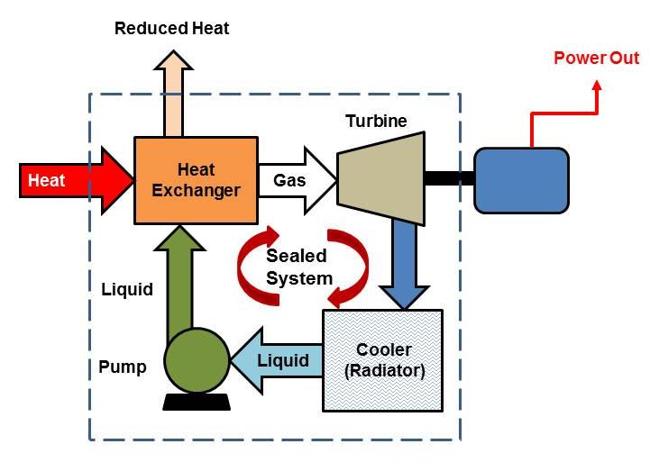
The cement industry is one of the most energy-intensive industries globally, with a significant portion of the energy consumed being released as waste heat. The production of cement clinkers, the intermediate product formed by heating limestone, clay, and other materials to high temperatures in a rotary kiln, generates substantial amounts of waste heat, particularly in the form of hot gases and exhaust heat. This waste heat presents a valuable opportunity for energy recovery, particularly through systems designed to convert it into electricity.
In this context, waste heat recovery systems (WHRS) are becoming increasingly important in the cement industry. They allow cement plants to use the heat generated during clinker production to drive turbines or engines for power generation, reducing the reliance on external energy sources and lowering the plant’s operational costs. This section discusses the process of generating electricity using waste heat from cement clinker production, the systems involved, and the challenges and benefits associated with such systems.
1. The Waste Heat Recovery Process in Cement Clinker Production
Cement clinker production is characterized by high-temperature processes. The rotary kiln, where the raw material is heated to around 1450°C, generates a significant amount of waste heat in the form of exhaust gases. These gases are often vented into the atmosphere without being utilized, resulting in lost energy.
The waste heat recovery process aims to capture and convert this heat into usable energy. The basic steps involved in recovering waste heat for power generation from cement clinker production are as follows:
a. Capturing Waste Heat
The first step in the process is to capture the heat from the exhaust gases produced by the kiln and other parts of the cement plant. The exhaust gases, which are typically between 300°C and 500°C, are directed through heat exchangers designed to transfer heat to a working fluid. These heat exchangers, often in the form of air-to-air or air-to-water exchangers, absorb the heat from the gases and transfer it to a medium that can be used to generate electricity.
b. Converting Heat to Electricity
Once the heat is captured and transferred to a working fluid (typically water, steam, or an organic fluid in systems such as Organic Rankine Cycle (ORC) systems), it can be used to drive a turbine or generator for electricity production. The ORC, for instance, uses an organic fluid with a lower boiling point than water, enabling it to operate efficiently at lower temperature heat sources, such as those typically found in cement production.
Alternatively, cement plants can use steam from captured waste heat to run a steam turbine, generating electricity in a traditional Rankine cycle setup. The captured heat can also be used for combined heat and power (CHP) systems, which produce both electricity and useful thermal energy.
c. Reuse of Generated Power
The electricity generated from the waste heat recovery system can be used to power the cement plant itself, reducing the plant’s reliance on the grid. Any excess electricity can be sold back to the grid, providing additional revenue and improving the plant’s financial performance.
By reducing the need for external electricity, the plant not only saves money but also contributes to reducing its environmental impact by decreasing overall energy consumption.
2. Types of Waste Heat Recovery Systems in Cement Plants
There are several types of waste heat recovery systems that cement plants can use to capture and convert the heat from clinker production into electricity. The selection of the appropriate system depends on the temperature of the waste heat, the size of the plant, and the economic considerations.
a. Organic Rankine Cycle (ORC) Systems
The Organic Rankine Cycle (ORC) system is one of the most widely used waste heat recovery technologies in industries like cement production. The ORC works by circulating an organic fluid that vaporizes at lower temperatures than water. This vapor drives a turbine that is connected to a generator, which produces electricity. The efficiency of ORC systems increases with the temperature of the waste heat, making them particularly suitable for cement plants that produce moderate-temperature waste heat in the range of 300°C to 500°C.
The ORC system has several advantages:
- It can operate efficiently with lower-grade waste heat.
- It has relatively low maintenance requirements.
- It can be integrated with existing cement plant infrastructure.
b. Steam Rankine Cycle (SRC) Systems
In the Steam Rankine Cycle (SRC) system, waste heat is used to produce steam, which drives a steam turbine connected to a generator for electricity production. This system is suitable for higher-temperature waste heat (above 400°C), making it a good choice for cement plants with higher-temperature exhaust gases.
The SRC system is well-established and widely used for power generation from steam, but it requires significant infrastructure, including a boiler to produce the steam and a turbine system to generate electricity. However, it is highly efficient when dealing with large-scale operations.
c. Combined Heat and Power (CHP) Systems
In combined heat and power (CHP) systems, both electricity and thermal energy are produced from the same waste heat source. In cement plants, this could mean using the steam produced from waste heat recovery to power a turbine for electricity generation while also using the remaining heat for other industrial processes, such as drying raw materials or heating water.
CHP systems are highly efficient, as they maximize the use of the captured heat. Cement plants with a significant demand for both electricity and thermal energy can benefit from CHP systems, as they provide an integrated solution for both energy needs.
3. Challenges in Waste Heat Recovery for Cement Plants
Despite the clear advantages of waste heat recovery systems in cement production, there are several challenges that must be addressed to make these systems successful.
a. High Capital Investment
The installation of waste heat recovery systems requires a significant initial capital investment. The cost of equipment, such as heat exchangers, turbines, and generators, as well as the infrastructure needed for integration into the existing cement plant, can be considerable. For many cement plants, especially smaller or older ones, securing the necessary capital for such an investment can be a barrier.
Solution: Cement plants can explore financing options such as energy performance contracts (EPCs), where the cost of the system is repaid through energy savings over time. Additionally, government incentives, tax credits, and grants for energy efficiency projects can help offset the capital costs.
b. Space and Integration Constraints
Integrating waste heat recovery systems into existing cement plants can be challenging, particularly in facilities with limited space or older infrastructure. The need for additional equipment, such as heat exchangers, turbines, and condensers, can require modifications to existing systems and processes.
Solution: Modern waste heat recovery systems, such as modular ORC units, are designed to be more compact and easier to integrate into existing plant infrastructure. A detailed feasibility study and careful planning are essential to ensure that space and integration issues are addressed effectively.
c. Maintenance and System Efficiency
Maintaining a waste heat recovery system to ensure optimal performance can be challenging, especially in plants with harsh operating conditions, such as high temperatures and exposure to abrasive dust. Over time, heat exchangers, turbines, and other components can wear out or become inefficient, which can lead to reduced energy recovery and lower electricity generation.
Solution: Regular maintenance, monitoring, and the use of advanced digital technologies (e.g., remote monitoring and predictive maintenance systems) can help ensure that the system operates efficiently. Additionally, selecting robust equipment designed for the harsh conditions found in cement plants can extend the lifespan and performance of the waste heat recovery system.
d. Variability in Waste Heat Availability
The availability and quality of waste heat can vary depending on the kiln operation and other factors in the cement production process. For instance, during certain periods, the temperature and flow of waste gases may fluctuate, which can impact the consistency of energy recovery.
Solution: Energy storage solutions, such as thermal energy storage systems, can help mitigate variability by storing excess heat when available and releasing it when needed. Hybrid systems that combine waste heat recovery with other renewable energy sources (e.g., solar or biomass) can also help provide more stable and reliable energy output.
4. Benefits of Waste Heat Recovery in Cement Plants
The adoption of waste heat recovery systems in cement clinker production offers several important benefits:
a. Reduced Energy Costs
By generating electricity from waste heat, cement plants can significantly reduce their reliance on purchased electricity. This reduces energy costs, which can account for a large portion of a cement plant’s operational expenses.
b. Improved Sustainability
Waste heat recovery contributes to the sustainability of cement production by reducing the carbon footprint of cement plants. By capturing and using waste heat, cement plants lower their overall energy consumption, leading to a reduction in greenhouse gas emissions.
c. Enhanced Energy Efficiency
Waste heat recovery systems enable cement plants to improve their energy efficiency. By utilizing heat that would otherwise be wasted, these systems help maximize the energy extracted from raw materials and reduce the need for additional fuel.
d. Financial Benefits
In addition to reducing energy costs, waste heat recovery systems can generate revenue through the sale of excess electricity to the grid. Moreover, the reduction in energy consumption and carbon emissions can make cement plants eligible for environmental incentives and subsidies, improving their financial performance.
5. Future Outlook for Waste Heat Recovery in Cement Production
As energy costs continue to rise and environmental regulations become stricter, the adoption of waste heat recovery systems in cement clinker production is expected to grow. Technological advancements, such as the development of more efficient ORC systems and better heat exchanger designs, will increase the feasibility and cost-effectiveness of these systems.
Additionally, with the global focus on reducing carbon emissions and improving industrial sustainability, cement plants that invest in waste heat recovery systems will not only improve their operational efficiency but also position themselves as leaders in the transition to greener, more sustainable manufacturing practices.
In conclusion, generating electricity from waste heat in cement clinker production presents a viable and effective way to improve energy efficiency, reduce costs, and minimize the environmental impact of cement plants. As the industry embraces these technologies, waste heat recovery will play an increasingly important role in the sustainable development of the cement sector.
6. Policy and Regulatory Support for Waste Heat Recovery in Cement Production
The success of waste heat recovery (WHR) systems in cement production is not only influenced by technology but also by the policy landscape and regulatory environment in which cement plants operate. As the world moves toward more sustainable industrial practices, governments and regulatory bodies have introduced various policies to encourage the adoption of energy-efficient technologies, including waste heat recovery.
a. National and International Energy Efficiency Standards
Many countries have established energy efficiency standards and targets that require industries, including cement plants, to improve their energy usage and reduce waste. Cement plants are often required to meet stringent energy performance benchmarks as part of national or international initiatives aimed at reducing industrial energy consumption.
Solution: Waste heat recovery can help cement plants meet these energy efficiency standards by capturing and utilizing excess heat. Compliance with these standards can be achieved through the integration of WHR systems, which help plants optimize their energy use, reduce overall energy demand, and minimize waste.
In some countries, compliance with energy efficiency regulations may also open the door to financial benefits, such as tax breaks, lower utility rates, or exemptions from certain regulatory fees, further incentivizing the adoption of WHR technologies.
b. Carbon Emission Reduction Programs
Given that cement production is a significant contributor to global CO2 emissions, many governments have implemented carbon emission reduction programs. Cement plants, which are large consumers of energy and emit substantial amounts of greenhouse gases, are often subject to carbon taxes or emissions trading systems (ETS). In response, these plants are under increasing pressure to reduce their carbon footprint.
Solution: Waste heat recovery can significantly reduce the carbon footprint of cement plants by decreasing the amount of fossil fuel needed for power generation. By recovering waste heat and using it to generate electricity or heat, cement plants can lower their overall energy consumption and CO2 emissions, making them more competitive in markets with carbon pricing mechanisms.
Further, waste heat recovery can help cement plants meet regulatory emissions reduction targets. In some cases, plants may receive credits for reducing their emissions through energy recovery measures, which can offset other emissions from the production process.
c. Financial Incentives for Waste Heat Recovery Technologies
Governments and international organizations offer various financial incentives to encourage the adoption of energy-efficient technologies, including waste heat recovery systems. These incentives may include grants, tax credits, or low-interest loans, which reduce the upfront cost of installing WHR systems.
Solution: Cement plants can benefit from these financial incentives to offset the capital costs associated with implementing waste heat recovery. By taking advantage of available government subsidies, tax credits, or low-interest financing options, plants can improve the financial feasibility of installing WHR systems, making these technologies more attractive and accessible.
d. International Commitments to Sustainable Manufacturing
As part of international climate agreements like the Paris Agreement, countries have committed to achieving net-zero emissions and fostering the transition to sustainable manufacturing. Cement plants are integral to this transformation, and international environmental organizations are increasingly focusing on the energy efficiency and sustainability of the cement industry.
Solution: Waste heat recovery can help cement plants align with international environmental goals by reducing energy consumption and improving carbon efficiency. As the global focus shifts toward sustainability, cement companies that adopt WHR technologies may be better positioned to meet international emissions reduction targets and maintain a competitive advantage in global markets.
7. Future Technological Developments in Waste Heat Recovery for Cement Plants
The potential for waste heat recovery in cement production is vast, and ongoing technological advancements are making these systems more efficient and cost-effective. These developments promise to enhance the ability of cement plants to recover and utilize waste heat for electricity generation, improving both their sustainability and energy efficiency.
a. Advanced Organic Rankine Cycle (ORC) Systems
While ORC systems are already widely used for waste heat recovery, ongoing advancements are increasing their efficiency and performance. Newer ORC technologies focus on optimizing the thermodynamic cycles to maximize electricity generation from lower-temperature waste heat sources, which are typical in cement production.
Innovative materials, such as advanced heat exchangers and working fluids, are also being explored to further improve system efficiency. For example, using a mixture of organic fluids with varying boiling points allows ORC systems to operate across a broader temperature range, making them more versatile for various industrial applications.
Solution: These advancements in ORC technology will allow cement plants to recover waste heat more efficiently, even from lower-temperature exhaust gases, and generate more electricity. As these systems become more affordable and efficient, they will become increasingly attractive for cement producers seeking to optimize energy recovery.
b. Heat Storage Technologies
One challenge with waste heat recovery systems is the intermittent nature of waste heat availability. The heat produced by cement plants may fluctuate throughout the day or across seasons, which can affect the consistency of power generation.
To address this challenge, researchers are developing thermal energy storage technologies, such as molten salt or phase-change materials, that can store excess heat for later use. These storage systems would allow cement plants to capture and store waste heat when it is abundant and then release it during periods of low heat availability, helping to balance supply and demand.
Solution: Thermal energy storage will improve the reliability of waste heat recovery systems by smoothing out fluctuations in waste heat availability. By integrating energy storage solutions with WHR systems, cement plants can achieve a more consistent and stable energy supply, reducing reliance on external power sources.
c. Hybrid Systems
Hybrid systems, which combine different waste heat recovery technologies, are gaining attention as a way to optimize energy recovery in cement plants. For example, combining ORC systems with steam Rankine cycles or integrating WHR with solar or biomass energy can create a more flexible and efficient energy system. Hybrid solutions can ensure that a plant can generate electricity from a variety of sources, making it more resilient to fluctuations in waste heat availability and external energy supply.
Solution: Hybrid systems offer the potential for cement plants to maximize energy recovery and improve operational efficiency. By diversifying their energy sources, plants can reduce their dependence on grid electricity, lower costs, and achieve greater energy resilience.
d. AI and Digital Optimization
The integration of artificial intelligence (AI) and machine learning into waste heat recovery systems is also a promising development. By using AI algorithms to optimize the operation of WHR systems in real-time, cement plants can achieve higher efficiency and lower energy costs. AI can monitor the performance of equipment, predict system failures, and optimize the use of captured waste heat based on production schedules and external energy prices.
Solution: The integration of AI into waste heat recovery systems can lead to significant operational improvements. Predictive maintenance, real-time optimization, and enhanced system monitoring will increase the lifespan and performance of WHR systems, ensuring higher returns on investment and more reliable power generation.
8. The Path Forward: Scaling Waste Heat Recovery in Cement Production
To fully realize the potential of waste heat recovery in cement production, several actions are required across the industry:
a. Standardization and Industry Best Practices
As waste heat recovery systems become more widespread, standardizing technologies and establishing industry best practices will help to reduce implementation costs and increase system reliability. Collaborations between industry players, technology providers, and regulators can help create standards that ensure optimal system performance and integration.
Solution: Industry associations and government bodies can play a crucial role in developing these standards, helping to streamline the adoption of waste heat recovery systems across cement plants globally.
b. Expanding Awareness and Knowledge Sharing
Many cement producers may not fully understand the potential benefits of waste heat recovery, or they may be unaware of the available technologies and incentives. Expanding awareness through knowledge-sharing platforms, industry conferences, and case studies is essential to encourage greater adoption of waste heat recovery technologies.
Solution: Creating educational resources, hosting workshops, and facilitating industry collaborations will help cement producers learn from successful case studies, making it easier for them to evaluate and adopt waste heat recovery technologies in their own operations.
c. Scaling Investment in Research and Development
Finally, increased investment in research and development will help accelerate the adoption of waste heat recovery in cement production. Continued innovation will drive down costs, improve system efficiency, and open up new opportunities for energy recovery, particularly in smaller or lower-temperature plants.
Solution: Public and private sector investments in R&D will help cement plants adopt the latest technologies, ensuring that waste heat recovery remains a viable and attractive option for improving energy efficiency in the sector.
9. Conclusion
Waste heat recovery offers significant potential for improving energy efficiency and sustainability in cement clinker production. By capturing and converting excess heat from cement production into electricity, cement plants can reduce operating costs, decrease carbon emissions, and enhance their competitiveness in a rapidly evolving energy landscape.
The adoption of waste heat recovery technologies, supported by favorable policies, technological advancements, and ongoing industry collaboration, will play a key role in shaping the future of cement production. As the industry embraces these innovations, waste heat recovery will continue to be a cornerstone of sustainable manufacturing practices in the cement sector.
10. Scaling Waste Heat Recovery in the Global Cement Industry
While the adoption of waste heat recovery (WHR) in cement production is gaining momentum, its widespread implementation is still limited in some regions. To scale waste heat recovery across the global cement industry, several factors must be addressed at both the industry and policy levels. Below, we outline key considerations for scaling WHR technologies in cement production worldwide.
a. Addressing Regional and Economic Barriers
One of the main barriers to the widespread adoption of waste heat recovery systems in the cement industry is the economic disparity between regions. Cement plants in developed countries may have better access to capital, technology, and regulatory incentives, making it easier for them to implement WHR systems. However, in emerging markets or developing countries, cement plants may face higher financial constraints, and the initial investment in WHR systems may be difficult to justify without clear incentives.
Solution: Governments and international organizations can provide targeted financial support, including low-interest loans, subsidies, or carbon credits, to help facilitate the adoption of WHR technologies in developing regions. Additionally, cement producers in emerging markets may benefit from international collaboration, knowledge-sharing initiatives, and technology transfer programs to overcome technical and economic barriers.
b. Providing Financial Support and Investment
For cement plants, the high upfront capital cost associated with the installation of waste heat recovery systems remains a significant challenge. Cement companies often face tight margins due to the capital-intensive nature of cement production, making it difficult for them to invest in new technologies without clear and immediate returns on investment.
Solution: Innovative financial mechanisms, such as green bonds or public-private partnerships, can help secure the necessary capital for WHR systems. The use of energy performance contracts (EPCs) or third-party financing models can allow cement plants to install WHR technologies and repay the costs through energy savings over time. This financial model reduces the initial investment burden on cement producers, making it more feasible for them to implement waste heat recovery.
c. Government Regulations and Incentives
Incentive policies and regulatory frameworks play a crucial role in accelerating the adoption of WHR systems in the cement industry. While some countries have introduced carbon pricing mechanisms or energy efficiency regulations to encourage energy recovery, other regions may lack sufficient regulatory incentives to make these systems financially viable.
Solution: Governments can expand and improve incentive programs to support waste heat recovery. These could include direct subsidies, tax credits, or carbon trading credits. Additionally, governments can set clear long-term regulatory frameworks that encourage cement plants to invest in waste heat recovery and other energy-efficient technologies. For instance, aligning national climate targets with industrial energy efficiency programs can create a strong business case for cement producers to adopt WHR systems.
11. The Role of Circular Economy in Cement Industry Sustainability
The integration of waste heat recovery into the cement industry is aligned with the principles of a circular economy, where energy and resources are reused, and waste is minimized. Cement production, traditionally seen as one of the most energy-intensive and carbon-heavy industries, is increasingly moving towards more sustainable practices that embrace circular economy principles.
a. Waste Heat as a Resource
Rather than treating heat as a by-product of cement production, plants are beginning to view it as a valuable resource that can be reused to generate power or support other industrial processes. The adoption of waste heat recovery systems is an essential part of this shift towards circular economy practices.
By converting waste heat into electricity, cement plants contribute to the reduction of waste heat emissions and make more efficient use of the raw materials and energy in their production processes. This not only reduces the environmental impact of cement production but also helps lower overall operational costs.
b. Combining Waste Heat with Alternative Fuels
In the context of a circular economy, many cement plants are also moving towards the use of alternative fuels, such as biomass, waste materials, or industrial by-products, to replace traditional fossil fuels. The combination of waste heat recovery with alternative fuels further reduces the carbon intensity of cement production.
For example, waste heat can be used to generate power for the cement plant while alternative fuels can reduce the consumption of coal or natural gas in the production process. This integrated approach results in a more sustainable and resilient cement production process, with reduced waste and energy consumption.
Solution: By embracing circular economy principles, cement producers can further reduce their environmental footprint while improving energy efficiency. Waste heat recovery, when combined with alternative fuels and other energy efficiency measures, contributes to creating a more sustainable and self-sufficient production cycle.
12. Conclusion: The Future of Waste Heat Recovery in the Cement Industry
The potential for waste heat recovery in the cement industry is vast, offering significant benefits in terms of energy efficiency, cost reduction, and environmental impact. As global demands for sustainable industrial practices continue to rise, cement plants will need to adopt energy-efficient technologies such as WHR systems to stay competitive and comply with increasingly stringent environmental regulations.
To achieve widespread adoption of waste heat recovery, it will be essential for the cement industry to overcome financial, technological, and regulatory barriers. Through targeted investments in research and development, financial incentives, and policy support, waste heat recovery can become a cornerstone of sustainable cement production worldwide.
Moreover, the combination of waste heat recovery with circular economy principles, alternative fuels, and renewable energy sources presents an exciting opportunity for cement plants to transition to more sustainable and energy-efficient production methods. As technology advances and collaboration between industry, government, and academia continues, the cement sector can become a leader in the global effort to reduce industrial energy consumption and combat climate change.
Ultimately, the successful integration of waste heat recovery into cement production will not only provide financial and environmental benefits but will also serve as a model for other industries looking to harness waste heat as a valuable resource in the transition to a more sustainable and low-carbon economy.
13. Generating Electricity Using Waste Heat from Cryogenic Processes
Cryogenic processes involve the production and use of extremely low temperatures to liquefy gases such as nitrogen, oxygen, and natural gas. These processes are commonly found in industries such as the production of liquefied natural gas (LNG), air separation, and cryogenic refrigeration. As cryogenic processes are highly energy-intensive, they also generate a significant amount of waste heat, which can be harnessed for electricity generation. The integration of waste heat recovery systems in cryogenic processes is a promising way to improve energy efficiency, reduce operational costs, and lower carbon emissions.
a. Understanding Cryogenic Processes and Waste Heat Generation
Cryogenic processes typically operate at temperatures well below -150°C (-238°F), requiring substantial amounts of energy for refrigeration and liquefaction. The energy used to achieve these low temperatures is often derived from the combustion of fossil fuels or electricity from the grid, resulting in substantial waste heat during the process.
While the low temperatures are necessary for the liquefaction of gases, the systems involved in cryogenic cooling (such as compressors and heat exchangers) release waste heat into the environment. This waste heat, often in the form of high-temperature exhaust gases or hot fluids, can be captured and converted into usable power.
b. Technology for Recovering Waste Heat in Cryogenic Processes
Several technologies are used to recover waste heat from cryogenic processes. These systems typically focus on utilizing the heat from warm exhaust gases or fluids that are emitted during the refrigeration or compression stages. Key technologies for recovering waste heat from cryogenic processes include:
- Organic Rankine Cycle (ORC): ORC is a heat recovery technology that can efficiently convert waste heat into electricity, even at lower temperatures typically found in cryogenic processes. In an ORC system, organic fluids with a lower boiling point than water are used to operate a turbine, generating electricity as the waste heat evaporates the fluid.
- Kalina Cycle: The Kalina Cycle is a thermodynamic process that uses a mixture of water and ammonia as a working fluid. It is more efficient than traditional Rankine cycles, especially when dealing with heat at medium to low temperatures, which is common in cryogenic applications. The Kalina Cycle allows for a higher degree of flexibility in heat recovery and can improve the overall efficiency of the energy conversion process.
- Regenerative Heat Exchange: In some cryogenic plants, waste heat recovery can be integrated directly into the cooling systems by using regenerative heat exchangers. These exchangers capture waste heat and use it to pre-heat incoming fluids, reducing the need for additional energy input to achieve the required temperatures.
- Thermoelectric Generators (TEGs): Although still under development for large-scale applications, thermoelectric generators (TEGs) offer a potential solution for directly converting temperature differences (such as those found in cryogenic processes) into electricity. TEGs use semiconductor materials to generate electrical power when exposed to heat differentials, potentially allowing for efficient waste heat recovery.
c. Applications of Waste Heat Recovery in Cryogenic Industries
- Liquefied Natural Gas (LNG) Production: LNG production involves the cryogenic cooling of natural gas to transform it into a liquid state for storage and transport. The process of cooling natural gas generates significant waste heat, which can be captured and converted into electricity. By using ORC or Kalina cycles, LNG plants can recover waste heat and improve the overall energy efficiency of their operations. This process reduces the plant’s reliance on external energy sources, such as the grid, and lowers operational costs.
- Air Separation Units (ASUs): Air separation plants, which produce oxygen, nitrogen, and argon, use cryogenic processes to separate gases based on their boiling points. The cooling and compression stages of air separation generate significant amounts of waste heat. By integrating waste heat recovery technologies, such as ORC or regenerative heat exchangers, air separation plants can convert waste heat into useful electricity, enhancing their energy efficiency and reducing environmental impact.
- Cryogenic Refrigeration Systems: Cryogenic refrigeration is used in various applications, from medical and industrial refrigeration to the storage of perishable goods. Cryogenic refrigeration systems, like those used in cold storage or deep-freeze applications, generate waste heat as a by-product. Utilizing waste heat recovery methods allows these systems to improve efficiency, reduce costs, and contribute to a more sustainable refrigeration process.
- Liquefaction of Hydrogen: Hydrogen liquefaction involves the cryogenic cooling of hydrogen gas, which requires significant energy input. The waste heat generated during hydrogen liquefaction can be recovered using ORC or Kalina cycles to produce electricity, offsetting some of the energy requirements of the liquefaction process. As hydrogen plays a key role in clean energy transitions, recovering waste heat from its liquefaction can make hydrogen production more cost-effective and sustainable.
d. Benefits of Waste Heat Recovery in Cryogenic Processes
- Energy Efficiency Improvement: Cryogenic processes are inherently energy-intensive. Waste heat recovery systems help optimize the energy usage by converting waste heat into usable electricity, reducing the need for external energy sources. This results in overall energy efficiency improvements in cryogenic facilities.
- Reduced Operational Costs: The recovery of waste heat reduces reliance on purchased electricity or fuels, resulting in lower operational costs for cryogenic plants. With the rising costs of energy, this can lead to significant cost savings over time, improving the financial viability of cryogenic operations.
- Lower Environmental Impact: By utilizing waste heat for electricity generation, cryogenic processes can reduce their overall carbon footprint. This is particularly relevant in industries like LNG production or hydrogen liquefaction, which are often energy-intensive and associated with high emissions. Waste heat recovery can help mitigate the environmental impact by reducing the need for additional fuel consumption and decreasing CO2 emissions.
- Enhanced System Reliability: Integrating waste heat recovery systems, such as ORC or Kalina cycles, with cryogenic processes can improve the overall reliability and resilience of the system. These technologies typically operate with low maintenance requirements and can increase the operational lifetime of the equipment by reducing the strain on the energy supply system.
e. Challenges and Considerations for Waste Heat Recovery in Cryogenic Processes
- Economic Viability: One of the primary challenges for waste heat recovery in cryogenic processes is the high capital cost of implementing the necessary technology. Systems like ORC, Kalina cycles, or thermoelectric generators may have significant upfront costs. While the long-term energy savings can offset these costs, the initial investment may be a barrier for some companies.
- Temperature and Heat Source Compatibility: Cryogenic processes typically involve very low temperatures, which may not be optimal for all waste heat recovery technologies. For example, conventional Rankine cycles may not be effective at low temperatures, but newer technologies like Kalina or ORC systems, which are designed to operate at lower temperature differentials, can improve efficiency.
- Integration Complexity: Integrating waste heat recovery into existing cryogenic plants may require significant retrofitting, especially in older facilities. The complexity of such integration will depend on the type of cryogenic process, the amount of waste heat produced, and the specific recovery technology chosen. Advanced planning and engineering are necessary to ensure successful integration.
- Regulatory and Market Conditions: In some regions, the adoption of waste heat recovery technologies may be hampered by regulatory barriers or a lack of financial incentives. Governments and regulatory bodies play a crucial role in incentivizing the adoption of energy-efficient technologies by providing subsidies, tax credits, or other financial mechanisms that make waste heat recovery more attractive to cryogenic process operators.
f. Future Outlook
As global energy efficiency standards become more stringent and as industries seek to reduce their carbon footprints, the role of waste heat recovery in cryogenic processes will continue to grow. Ongoing research and development into new technologies and materials will further improve the efficiency of waste heat recovery systems, making them even more suitable for a wider range of applications.
The future of waste heat recovery in cryogenic processes looks promising, particularly as industries like LNG production, air separation, and hydrogen liquefaction become more integrated into the global push for sustainable energy. As technology advances and financial incentives improve, the widespread adoption of waste heat recovery in cryogenic industries will contribute significantly to reducing energy consumption, lowering operating costs, and mitigating climate change.
14. Conclusion: Harnessing Waste Heat in Cryogenic Processes
The integration of waste heat recovery technologies into cryogenic processes offers significant opportunities for energy efficiency improvements, cost savings, and environmental benefits. By capturing and converting waste heat into electricity, industries that rely on cryogenic processes can not only optimize their energy usage but also reduce their environmental impact. As advancements in waste heat recovery technologies continue and the financial and regulatory environment becomes more supportive, the adoption of these systems will become an essential aspect of sustainable cryogenic operations worldwide.
15. Key Considerations for Optimizing Waste Heat Recovery in Cryogenic Processes
In order to maximize the potential of waste heat recovery from cryogenic processes, it is important to understand the technical and operational factors that influence the performance of these systems. Optimizing waste heat recovery not only improves efficiency but also ensures the long-term sustainability and financial viability of the system. Below, we outline some key considerations for achieving optimal waste heat recovery in cryogenic processes.
a. Heat Source Temperature and Heat Recovery Efficiency
The efficiency of a waste heat recovery system is significantly impacted by the temperature of the waste heat source. Cryogenic processes typically operate at extremely low temperatures, which may not always be ideal for conventional waste heat recovery technologies. For instance, standard Rankine cycle systems are less efficient at lower temperature differentials.
Solution: To overcome this challenge, advanced technologies like Organic Rankine Cycles (ORC), Kalina Cycles, and thermoelectric generators (TEGs) are better suited for the low-temperature heat produced by cryogenic processes. These systems are designed to operate efficiently even at lower temperatures, enabling better recovery and conversion of waste heat into useful electricity.
Additionally, the efficiency of heat exchangers plays a key role in improving recovery. Enhanced heat exchanger designs, such as plate heat exchangers or spiral heat exchangers, can improve heat transfer efficiency by maximizing surface area for heat exchange.
b. Matching Waste Heat Recovery Systems to Process Demand
Cryogenic processes typically involve fluctuations in heat generation, depending on the specific production cycle. For example, in LNG production, the cooling and compression stages may not generate waste heat at constant rates. Understanding the varying waste heat levels and matching them to appropriate recovery systems is crucial for optimizing the system’s performance.
Solution: Flexible waste heat recovery systems that can dynamically adjust to varying heat inputs are essential for improving the overall efficiency. For example, systems with variable capacity, such as modular ORC systems, can be designed to scale up or down according to the amount of waste heat available. This flexibility ensures that the system remains effective during different operating conditions, reducing energy waste and improving system reliability.
Additionally, integrating energy storage systems, such as thermal energy storage or battery storage, can allow excess electricity generated during peak heat recovery times to be stored and used when heat generation is low. This ensures that the system can continuously provide energy even during periods of low heat production.
c. Maintenance and Operational Considerations
As with any industrial system, maintaining optimal operation of waste heat recovery technologies in cryogenic processes requires regular monitoring and maintenance. Failure to address wear and tear on components such as heat exchangers, turbines, or compressors can result in reduced efficiency and increased downtime.
Solution: Regular maintenance schedules and predictive maintenance techniques, such as monitoring system performance through sensors and data analytics, can help identify potential issues before they lead to failures. Predictive maintenance allows operators to anticipate wear and tear on components and replace them as needed, preventing unexpected downtime and ensuring the consistent performance of waste heat recovery systems.
Furthermore, training operators to recognize the specific needs of waste heat recovery technologies in cryogenic environments will help ensure efficient operation. This includes understanding the limitations of different heat recovery methods, such as their response to changes in heat source temperature, and knowing how to optimize system parameters based on operational conditions.
d. Integration with Existing Infrastructure
One of the biggest challenges for implementing waste heat recovery systems in cryogenic plants is integrating the new systems into existing infrastructure. Cryogenic processes are often highly complex, and retrofitting waste heat recovery solutions into these systems can require significant modifications to plant design.
Solution: Careful planning and engineering assessments are required before retrofitting a waste heat recovery system into an existing plant. The existing heat generation points, fluid flow systems, and available space for additional equipment must all be considered. In many cases, modular or compact systems can be used to integrate waste heat recovery with minimal disruption to the existing operations.
Additionally, developing a comprehensive energy management strategy for the plant is essential. By analyzing the plant’s energy consumption patterns and identifying the best locations for heat recovery systems, plant managers can make informed decisions that minimize the cost of retrofitting and maximize the overall energy savings.
e. Role of Digitalization and Smart Technologies
Digitalization and the use of smart technologies are increasingly playing a key role in optimizing energy use and system performance. Advanced data analytics, Internet of Things (IoT) sensors, and real-time monitoring systems provide critical insights into the behavior of both cryogenic processes and waste heat recovery systems.
Solution: By implementing digital tools, plant operators can continuously monitor temperature, pressure, flow rates, and other parameters, allowing for more precise control over waste heat recovery systems. Machine learning algorithms can predict system performance based on historical data, enabling operators to adjust operational settings to maximize efficiency. Predictive analytics can also identify areas for improvement, such as optimizing the heat exchange process or detecting inefficiencies in the system before they result in downtime or lost energy.
Integrating digital technologies with waste heat recovery systems also enhances the ability to coordinate with energy storage systems, improve heat exchanger performance, and ultimately provide a more reliable and optimized energy recovery solution.
16. Case Studies of Waste Heat Recovery in Cryogenic Processes
Several industries have successfully implemented waste heat recovery systems in their cryogenic operations, demonstrating the feasibility and potential benefits of this technology. Here are a few case studies showcasing how waste heat from cryogenic processes has been harnessed to generate electricity:
a. Case Study 1: LNG Plant in Qatar
A liquefied natural gas (LNG) plant in Qatar implemented an ORC-based waste heat recovery system to harness the waste heat generated during the LNG production process. The system was designed to recover waste heat from the hot exhaust gases produced during the cryogenic cooling of natural gas. The recovered heat was used to generate electricity, which was fed back into the plant’s power grid, offsetting energy consumption from external sources.
The implementation of this system led to a reduction in the plant’s reliance on grid power and significantly lowered operational costs. Additionally, it contributed to the plant’s sustainability goals by reducing its carbon emissions, as less electricity had to be purchased from the grid.
b. Case Study 2: Air Separation Unit in the United States
An air separation unit (ASU) in the United States incorporated a Kalina cycle for waste heat recovery from its cryogenic cooling process. The Kalina cycle was chosen because of its efficiency at recovering low-grade waste heat, which is common in air separation plants.
The installation of the waste heat recovery system allowed the ASU to generate a significant amount of electricity, reducing its dependence on external power sources. The system also improved the overall energy efficiency of the plant, which helped reduce its environmental footprint. The success of the system led to a subsequent rollout of waste heat recovery technology at other ASUs across the company’s network.
c. Case Study 3: Hydrogen Liquefaction Plant in Germany
A hydrogen liquefaction plant in Germany used waste heat recovery technology to reduce the energy costs associated with hydrogen production. By capturing waste heat generated during the cryogenic liquefaction of hydrogen, the plant was able to generate electricity that was used to power the liquefaction process itself, thereby reducing the amount of external electricity required.
This integration of waste heat recovery significantly improved the energy efficiency of the plant, which is critical for the cost-effective production of liquid hydrogen. The plant’s successful implementation has paved the way for other hydrogen producers to adopt similar technologies in the pursuit of green hydrogen production.
17. Conclusion: The Future of Waste Heat Recovery in Cryogenic Industries
Waste heat recovery in cryogenic processes is poised to play an increasingly important role in the energy transition. As the world moves toward cleaner and more energy-efficient industrial processes, the ability to capture and repurpose waste heat from cryogenic operations represents a critical opportunity for reducing energy consumption, cutting costs, and lowering environmental impact.
With continued advancements in waste heat recovery technologies, the integration of these systems into cryogenic processes will become more efficient, cost-effective, and widespread. In addition, the digitalization of industrial processes, alongside the ongoing development of energy storage and smart technologies, will enhance the performance of these systems, enabling real-time optimization and more sustainable operations.
By embracing waste heat recovery, industries involved in cryogenic processes, such as LNG production, air separation, and hydrogen liquefaction, can take significant strides toward achieving their energy efficiency and sustainability goals. As these technologies continue to evolve, the future of cryogenic industries will be defined by their ability to harness every possible source of energy, turning waste into valuable resources.
18. The Role of Policy and Regulations in Promoting Waste Heat Recovery in Cryogenic Industries
While technological advancements are crucial to the widespread adoption of waste heat recovery in cryogenic processes, the role of policy and regulations cannot be underestimated. Governments and regulatory bodies have a significant influence on the adoption of energy-efficient technologies by establishing standards, providing incentives, and encouraging sustainable practices. In many regions, the push toward reducing carbon emissions and improving energy efficiency is prompting industries to seek ways to optimize their operations, including capturing and utilizing waste heat. Here, we explore how policy and regulations can support waste heat recovery in cryogenic industries.
a. Energy Efficiency Standards and Regulations
Governments around the world are increasingly setting stricter energy efficiency standards for industrial operations, including those in the cryogenic sector. These regulations are designed to encourage companies to adopt more efficient technologies, including waste heat recovery systems. For example, in the European Union, the Energy Efficiency Directive requires member states to establish national energy efficiency action plans and take steps to improve energy efficiency in both industrial and non-industrial sectors. Similar regulations exist in countries like the United States, where the Energy Independence and Security Act (EISA) sets energy efficiency standards for various industries.
Solution: By setting mandatory energy efficiency targets and encouraging the adoption of advanced technologies like waste heat recovery, these regulations create a financial and operational incentive for companies in cryogenic industries to improve their energy performance. In some cases, industries that do not comply with these regulations may face penalties, while those that exceed standards could be rewarded with tax incentives or subsidies.
b. Financial Incentives and Subsidies
Financial incentives play a critical role in making waste heat recovery technologies more accessible to industries. Governments may provide tax credits, grants, or other forms of financial support to businesses that invest in energy-saving technologies, including waste heat recovery systems. For instance, in the United States, the Department of Energy’s Advanced Manufacturing Office offers funding opportunities for projects focused on improving energy efficiency in industrial processes, which could include waste heat recovery in cryogenic processes.
Solution: Financial incentives lower the upfront costs of implementing waste heat recovery systems, which can be a significant barrier for cryogenic industry players. With the support of subsidies, grants, or low-interest loans, companies are more likely to adopt these technologies and achieve energy efficiency goals without bearing the full financial burden.
In addition, carbon credits or emissions trading schemes can be another form of incentive for companies that reduce their carbon footprint through waste heat recovery. These programs allow companies to earn credits for reducing greenhouse gas emissions, which can then be sold or traded to offset emissions elsewhere.
c. Environmental Regulations and Emissions Reduction Targets
Environmental regulations, particularly those aimed at reducing greenhouse gas emissions, are driving industries to adopt more sustainable practices. Many cryogenic processes, such as LNG production and hydrogen liquefaction, are energy-intensive and emit significant amounts of carbon dioxide (CO2). In many countries, there are now stringent emissions reduction targets that mandate a reduction in CO2 emissions from industrial operations. For example, the Paris Agreement has set ambitious global climate goals that countries are obligated to meet, which include a substantial reduction in industrial emissions.
Solution: The implementation of waste heat recovery systems can significantly reduce a company’s carbon footprint by lowering energy consumption and decreasing reliance on fossil fuels. Companies can thus contribute to meeting emissions reduction targets while also benefiting from the efficiency improvements and cost savings provided by these systems.
As part of emissions reduction strategies, governments may encourage or mandate the adoption of technologies that reduce waste heat generation or capture and repurpose waste heat to generate electricity, thereby helping to achieve global and national climate goals.
d. Voluntary Certifications and Sustainability Initiatives
In addition to mandatory regulations, voluntary certifications and sustainability initiatives also play a significant role in promoting waste heat recovery. For instance, programs such as the Leadership in Energy and Environmental Design (LEED) certification and ISO 50001 (Energy Management Systems) encourage companies to adopt best practices in energy efficiency and sustainability. Companies that participate in these programs can achieve greater market recognition and potentially improve their competitive advantage.
Solution: By adhering to these voluntary standards and certifications, companies in cryogenic industries can demonstrate their commitment to sustainability. Waste heat recovery systems are often part of these initiatives, as they help reduce overall energy consumption and environmental impact. This can improve the company’s brand image and reputation, attracting environmentally conscious customers and investors.
Furthermore, international programs like the United Nations Global Compact or the Global Reporting Initiative (GRI) encourage companies to disclose their environmental performance, including energy usage and carbon emissions. Companies that adopt waste heat recovery technologies can highlight these efforts in their sustainability reports to demonstrate their contribution to the global sustainability agenda.
e. Public-Private Partnerships (PPPs) and Collaborative Research
Another way that policy can promote waste heat recovery in cryogenic industries is through public-private partnerships (PPPs) and collaborative research programs. Governments can partner with industry players to fund and develop new technologies, pilot projects, and best practices for waste heat recovery. This collaboration not only accelerates the development of cutting-edge waste heat recovery systems but also helps to de-risk investments for private companies by sharing the costs and benefits of new technology.
Solution: PPP programs can provide cryogenic industries with the resources needed to test new waste heat recovery technologies in real-world environments, reducing the financial risks associated with early-stage technology adoption. For example, joint government-industry efforts could help optimize ORC and Kalina cycle systems for use in cryogenic applications, which may not be commercially viable without such collaborations. Furthermore, these partnerships help facilitate knowledge sharing and best practices that can drive wider adoption of waste heat recovery technologies.
f. Global Efforts to Promote Sustainable Practices in Cryogenic Industries
The global push for sustainable development is having a profound impact on industries worldwide, including the cryogenic sector. International agreements such as the Paris Agreement and the United Nations Sustainable Development Goals (SDGs) are setting ambitious targets for energy efficiency, emissions reduction, and the transition to clean energy. In response, countries and industries are adopting more sustainable practices, with waste heat recovery playing an important role.
Solution: The global momentum towards sustainability is encouraging cryogenic industries to adopt waste heat recovery as part of their overall energy and environmental strategies. International organizations, like the International Energy Agency (IEA), are providing guidance on best practices and sharing knowledge on how industries can implement waste heat recovery systems to improve energy efficiency.
Through global efforts and cross-border collaboration, cryogenic industries are aligning with international sustainability targets and contributing to the broader goal of reducing carbon emissions and mitigating climate change.
19. The Future of Waste Heat Recovery in Cryogenic Industries
As technological advancements continue to evolve and the global demand for energy efficiency increases, the future of waste heat recovery in cryogenic industries looks promising. Emerging innovations in materials, systems, and processes will continue to make waste heat recovery more effective and economical. For example:
- Advanced Heat Exchanger Materials: New materials, such as nanomaterials or phase-change materials, are being researched to improve heat exchange efficiency. These materials could enhance the performance of heat exchangers in cryogenic applications, allowing for greater recovery of low-temperature waste heat.
- Hybrid Systems: The combination of different waste heat recovery technologies (such as ORC, Kalina cycles, and thermoelectric generators) in hybrid systems could offer even greater efficiency in recovering energy from cryogenic processes. Hybrid systems would allow for the optimization of recovery based on different heat sources and temperature conditions.
- Artificial Intelligence and Machine Learning: AI and machine learning could be used to optimize the operation of waste heat recovery systems in cryogenic industries by predicting heat load variations, monitoring system health, and adjusting operational parameters in real time. These technologies can improve system performance, extend the lifespan of equipment, and reduce energy losses.
- Decarbonization of Cryogenic Operations: As the demand for hydrogen, LNG, and other cryogenic gases increases, the pressure on the cryogenic industry to decarbonize will rise. Waste heat recovery will play an integral part in reducing the carbon intensity of these processes, supporting the transition to a low-carbon economy.
Conclusion: Optimizing Energy Use and Reducing Environmental Impact
Waste heat recovery in cryogenic processes is a vital strategy for improving energy efficiency, reducing operational costs, and mitigating environmental impacts. By utilizing the excess heat generated during cryogenic operations, industries can convert it into valuable electricity and enhance their overall sustainability.
With the continued development of innovative technologies, supportive policies, and international collaboration, the role of waste heat recovery in cryogenic industries will grow, driving the sector toward a more energy-efficient, cost-effective, and environmentally responsible future.
20. Generating Electricity Using Heat from Desalination Plants
Desalination plants are increasingly essential in regions with limited access to fresh water. These plants convert seawater into potable water by removing salts and minerals, a process that requires significant amounts of energy, usually in the form of heat or mechanical energy. One of the largest sources of energy consumption in desalination plants comes from the thermal processes, such as Multi-Stage Flash (MSF) distillation or Multi-Effect Distillation (MED), which rely heavily on heat to evaporate and condense seawater.
Fortunately, much of this heat is released as waste heat, which can be recovered and converted into electricity, improving the energy efficiency of desalination processes and contributing to sustainable energy production. Below, we explore how waste heat from desalination plants can be used to generate electricity, the technologies involved, and the potential benefits of this approach.
a. Understanding the Heat Generation in Desalination Plants
Desalination plants generate heat in various stages of the process. For instance, during MSF and MED processes, seawater is heated and vaporized to separate the freshwater from the salt. This heat is usually produced by burning fossil fuels, or in some cases, by nuclear or solar energy. The waste heat from these processes is released to the environment or lost, representing a potential energy resource.
In addition to MSF and MED, Reverse Osmosis (RO) desalination systems, although not as reliant on heat as thermal desalination processes, still produce waste heat due to the high-pressure pumps and equipment involved. Even though RO systems are more energy-efficient in comparison to thermal methods, the opportunity for waste heat recovery still exists.
b. Heat Recovery and Electricity Generation
The concept of generating electricity from waste heat in desalination plants follows similar principles to waste heat recovery in other industrial processes. The heat from the desalination plant can be harnessed using various systems, most commonly heat engines, thermoelectric generators (TEGs), or Organic Rankine Cycles (ORC).
- Organic Rankine Cycle (ORC): ORC is one of the most suitable technologies for converting waste heat into electricity, particularly at low to medium temperature ranges (around 100°C to 300°C). In an ORC system, waste heat is used to vaporize an organic fluid with a lower boiling point than water. This vapor then drives a turbine, which is connected to a generator to produce electricity. Afterward, the vapor is cooled and condensed to be reused in the cycle.In desalination plants, ORC systems can capture the waste heat from the distillation or reverse osmosis processes and convert it into useful electricity. ORC systems are particularly effective in regions where desalination plants operate continuously and have access to a constant supply of waste heat.
- Kalina Cycle: The Kalina cycle is another advanced waste heat recovery technology, similar to ORC but utilizing a mixture of water and ammonia as the working fluid. This cycle can be more efficient than traditional ORC systems in certain applications because it allows for a wider range of temperature and pressure conditions. The Kalina cycle is particularly useful in desalination plants that produce relatively low-temperature waste heat.
- Thermoelectric Generators (TEGs): TEGs convert temperature differences directly into electrical energy by using materials that generate a voltage when exposed to a heat gradient. These systems are well-suited for small-scale electricity generation from waste heat, particularly where temperature differentials are modest. In desalination plants, TEGs could be deployed at various points to capture heat released from seawater desalination processes and convert it into electricity, albeit at lower efficiency compared to ORC or Kalina systems.
- Heat Engines (Rankine and Stirling Engines): A heat engine, such as a steam Rankine cycle engine or a Stirling engine, can also be used to generate electricity from waste heat. These engines use the heat from the desalination plant to drive a mechanical engine, which then drives a generator. Stirling engines, in particular, are attractive because they can operate with a range of heat sources and offer a relatively simple mechanical design.Steam Rankine engines are more commonly used in large-scale applications where the temperature of the waste heat is high enough to generate steam, which can then be used to turn a turbine for electricity generation.
c. Integration with Desalination Plants
Integrating electricity generation systems into desalination plants requires careful planning and design to ensure that the heat recovery process does not interfere with the plant’s primary function: producing potable water. This integration involves several key factors:
- Heat Recovery System Placement: Heat recovery systems, such as ORC, need to be placed at strategic points where the waste heat is readily available. For thermal desalination processes like MSF or MED, the heat recovery system should be integrated into the distillation stage, where large amounts of waste heat are released.
- Energy Balance: The integration of a waste heat recovery system must be carefully balanced with the plant’s overall energy consumption. The amount of electricity generated from waste heat recovery must offset the energy required for desalination, and ideally provide additional power for other plant operations or export to the local grid.
- System Scalability: For smaller desalination plants or those using reverse osmosis, waste heat recovery systems like ORC may not be as effective. In such cases, integrating smaller-scale systems such as thermoelectric generators or Stirling engines may be more practical. However, larger-scale thermal desalination plants with high waste heat potential can benefit significantly from larger ORC or Kalina systems.
- Optimization for Operational Conditions: Desalination plants often operate under varying environmental and operational conditions. Temperature fluctuations, seawater salinity, and seasonal changes can affect the availability and effectiveness of waste heat recovery systems. Advanced control systems, including digitalization and real-time monitoring, can help optimize the performance of these systems based on current plant conditions.
d. Potential Benefits of Waste Heat Recovery in Desalination Plants
- Reduced Energy Costs: One of the key benefits of recovering waste heat in desalination plants is the reduction in energy costs. Desalination is an energy-intensive process, and by generating electricity from waste heat, plants can reduce their reliance on external power sources, which can result in significant operational savings.
- Sustainability: Waste heat recovery helps reduce the environmental footprint of desalination plants by improving energy efficiency and decreasing the carbon emissions associated with energy generation. This aligns with global sustainability goals, as desalination is often used in water-scarce regions where renewable energy sources, such as solar or wind, may not be available in sufficient quantities.
- Energy Independence: By generating electricity from waste heat, desalination plants can become more self-sufficient in terms of energy supply. In remote or off-grid areas where access to a reliable electricity grid is limited, this energy independence is particularly important, ensuring that desalinated water is available without reliance on external energy sources.
- Supporting Local Grids: In some cases, the electricity generated from waste heat recovery can be fed back into the local power grid. This can be especially beneficial in regions with high energy demand and limited power generation capacity. In such scenarios, desalination plants can contribute to local grid stability by providing an additional source of electricity.
- Improved Process Efficiency: Integrating electricity generation from waste heat recovery not only reduces external energy requirements but also improves the overall process efficiency of desalination plants. This makes the operation more cost-effective and sustainable over time.
e. Challenges and Considerations
- Initial Investment Costs: While waste heat recovery systems can provide long-term cost savings, the initial investment required to install these systems can be significant. The capital cost of ORC, Kalina cycles, and other systems may deter some operators from adopting these technologies, especially in small- to medium-sized desalination plants.
- Technological Maturity: Some waste heat recovery technologies, particularly Kalina cycles and thermoelectric generators, are still evolving. While they show promise, their widespread commercial adoption may be limited by technical challenges and relatively lower efficiency compared to more established technologies like ORC.
- Operational Complexity: Integrating waste heat recovery into desalination plants adds another layer of complexity to plant operations. The heat recovery system must be carefully monitored and controlled to ensure that it operates efficiently without disrupting the desalination process. This requires skilled personnel and advanced control systems.
- Location-Specific Factors: The potential for waste heat recovery depends on the specific characteristics of each desalination plant, including the temperature of the waste heat, plant capacity, and the availability of suitable technologies. Waste heat recovery is most effective in thermal desalination processes, but for reverse osmosis systems, other energy-saving methods may be more appropriate.
f. Future Outlook and Technological Advancements
The future of generating electricity from heat in desalination plants looks promising, particularly with advancements in technology. Emerging solutions, such as hybrid systems combining waste heat recovery with renewable energy sources (e.g., solar thermal energy), could further enhance the sustainability of desalination operations. Additionally, ongoing research into more efficient thermoelectric materials, advanced heat exchanger designs, and optimized energy systems will continue to improve the feasibility of waste heat recovery in desalination.
As global demand for fresh water grows, and the need for energy-efficient desalination technologies increases, waste heat recovery will play an increasingly important role in reducing the environmental impact of desalination plants, making them more cost-effective and sustainable.
Conclusion: Maximizing the Potential of Waste Heat in Desalination
Generating electricity from the heat produced by desalination plants offers significant opportunities for improving energy efficiency, reducing operational costs, and enhancing sustainability. By recovering waste heat and converting it into electricity using technologies like ORC, Kalina cycles, and thermoelectric generators, desalination plants can reduce their reliance on external power sources, contribute to energy independence, and lower their carbon footprint. Although challenges exist in terms of costs, technological maturity, and integration, the continued development of waste heat recovery systems will unlock new potential for cleaner, more efficient desalination operations in the future.
21. The Role of Government and Policy in Promoting Waste Heat Recovery in Desalination Plants
The integration of waste heat recovery systems in desalination plants can be significantly influenced by government policies and regulations. Supportive policies, financial incentives, and international frameworks can play an essential role in accelerating the adoption of energy-efficient technologies, including those for waste heat recovery. Below, we explore the various ways in which government action and policy can support the development of waste heat recovery in desalination plants.
a. Regulatory Frameworks and Energy Efficiency Standards
Governments can introduce and enforce regulations aimed at improving the energy efficiency of desalination plants. Energy efficiency standards and regulations that require or encourage the adoption of waste heat recovery technologies can push desalination plants to reduce their energy consumption and environmental impact. For example, regulations may mandate that a certain percentage of waste heat be recovered for energy generation or used for other processes within the plant.
- Energy Efficiency Directives: Many countries have energy efficiency directives that encourage industries, including desalination plants, to implement energy-saving measures. The European Union’s Energy Efficiency Directive, for instance, requires member states to create national energy efficiency action plans, which could include guidelines for recovering waste heat in desalination plants.
- Performance Standards: Governments could set performance standards for desalination plants that incentivize the implementation of energy recovery systems, including waste heat recovery. These standards may be tied to carbon reduction goals or broader climate action targets, prompting plant operators to optimize energy use and integrate heat recovery solutions.
b. Financial Incentives and Grants
Financial incentives are crucial to reducing the high initial costs associated with implementing waste heat recovery systems in desalination plants. Government subsidies, tax credits, and grants can help offset the capital costs of advanced technologies like ORC and Kalina cycles, which may otherwise be prohibitive for some operators, particularly in regions where desalination is not yet widespread.
- Subsidies and Tax Credits: Governments can offer direct subsidies or tax credits for companies that install waste heat recovery systems in desalination plants. These incentives help make the systems more financially viable, encouraging adoption.
- Grants for Research and Development: Governments can fund research and development (R&D) programs that focus on improving waste heat recovery technologies. By offering grants to research institutions and industry players, governments can foster innovation and make these technologies more effective, affordable, and suitable for large-scale implementation in desalination plants.
- Low-Interest Loans: In addition to grants and tax incentives, governments could offer low-interest loans for desalination plant operators to help finance the implementation of waste heat recovery systems. This type of financial assistance reduces the upfront financial burden on operators, making energy-efficient technologies more accessible.
c. International Collaborations and Global Standards
Waste heat recovery in desalination plants is a global concern, particularly in regions that rely heavily on desalinated water due to water scarcity. International cooperation and the adoption of global standards can help accelerate the development of heat recovery technologies and create a unified approach to sustainable desalination.
- International Frameworks: Global initiatives, such as the United Nations Sustainable Development Goals (SDGs), aim to promote water and energy efficiency worldwide. SDG 6 calls for “ensuring availability and sustainable management of water and sanitation for all,” while SDG 7 focuses on “ensuring access to affordable, reliable, sustainable, and modern energy for all.” Aligning desalination plant operations with these goals can drive policy changes that prioritize energy efficiency and waste heat recovery.
- Global Partnerships: Countries with advanced desalination infrastructure can collaborate with developing nations to share best practices, technologies, and funding opportunities for integrating waste heat recovery into desalination processes. These partnerships can help create more sustainable desalination operations on a global scale, addressing both water scarcity and energy efficiency challenges.
- International Standards: Governments can work together to establish international standards for waste heat recovery in desalination plants. These standards can set benchmarks for the amount of waste heat that must be recovered, ensuring that desalination operations worldwide adopt energy-efficient practices.
d. Public-Private Partnerships (PPP) for Innovation
Public-private partnerships (PPPs) can provide a collaborative model for deploying waste heat recovery technologies in desalination plants. Governments can partner with private companies, research institutions, and industry leaders to fund, pilot, and scale new technologies aimed at improving energy efficiency in desalination. Through PPPs, the risks and costs associated with implementing new systems are shared, making it easier for private companies to adopt innovative technologies.
- Joint Research Initiatives: Governments and private companies can collaborate on joint research projects to develop cutting-edge waste heat recovery solutions tailored to desalination processes. These projects could focus on improving the performance of existing technologies or developing entirely new systems that are more cost-effective and efficient.
- Pilot Projects: Governments can fund pilot projects that demonstrate the feasibility of waste heat recovery systems in desalination plants. These projects allow desalination plant operators to test and evaluate new technologies on a small scale before committing to full-scale implementation. Successful pilot projects can serve as models for broader adoption.
e. Carbon Pricing and Emissions Reduction Targets
Carbon pricing mechanisms, such as carbon taxes or cap-and-trade systems, can provide a strong financial incentive for desalination plants to adopt energy-efficient practices, including waste heat recovery. By incorporating the environmental cost of carbon emissions into the price of energy, carbon pricing encourages industries to find ways to reduce their carbon footprint.
- Carbon Taxes: Governments could implement carbon taxes that make it more expensive to use fossil fuels to power desalination plants. This would incentivize plant operators to explore more energy-efficient and sustainable options, such as waste heat recovery and renewable energy sources.
- Emissions Reduction Targets: Governments can set emissions reduction targets for industries, including desalination plants, as part of national climate action plans. By requiring a reduction in emissions, governments can push desalination plants to adopt waste heat recovery technologies to lower their overall carbon footprint.
f. Environmental Impact Assessments (EIAs)
Environmental Impact Assessments (EIAs) are often required for large-scale infrastructure projects, including desalination plants. These assessments evaluate the potential environmental impacts of a project, including energy use and greenhouse gas emissions. Governments can include specific requirements for waste heat recovery as part of the EIA process.
- Energy Efficiency as an EIA Criterion: Governments can include energy efficiency and waste heat recovery as key criteria in the EIA process for desalination projects. By requiring that waste heat recovery systems be incorporated into plant designs, governments ensure that new desalination projects are more sustainable and energy-efficient from the outset.
- Incentivizing Sustainable Design: During the EIA process, governments can provide additional points or incentives for projects that incorporate innovative energy-saving technologies, such as waste heat recovery systems. These incentives encourage developers to integrate sustainability into their designs, leading to more efficient and environmentally friendly desalination plants.
22. The Future of Waste Heat Recovery in Desalination
As the global demand for freshwater grows and the need for sustainable solutions intensifies, the future of waste heat recovery in desalination plants is increasingly important. With advancements in technology and greater policy support, desalination plants can become more energy-efficient and contribute to meeting both water and energy needs in a sustainable manner.
Some key trends and innovations that will shape the future of waste heat recovery in desalination include:
- Hybrid Systems: The combination of waste heat recovery systems with renewable energy sources, such as solar thermal or geothermal energy, could further reduce the environmental footprint of desalination. Hybrid systems can leverage both waste heat and renewable energy to power desalination processes, creating a more sustainable and cost-effective solution.
- Advanced Heat Recovery Materials: Research into new heat exchanger materials, such as nanomaterials or advanced polymers, will improve the efficiency of heat transfer in waste heat recovery systems. These materials could enhance the performance of heat recovery technologies, making them more effective even at lower temperatures.
- Decentralized Desalination: The future may see more decentralized desalination plants, particularly in remote or off-grid areas. These smaller, modular systems could integrate waste heat recovery to generate electricity locally, reducing reliance on external power sources and increasing energy self-sufficiency.
- Digitalization and Smart Grids: The use of digital technologies and smart grids in desalination plants will help optimize the operation of waste heat recovery systems. Sensors, real-time monitoring, and predictive analytics can be used to adjust energy recovery strategies based on changing operational conditions, ensuring maximum efficiency.
- Global Collaboration and Knowledge Sharing: As the need for fresh water becomes more critical, international collaboration will play a key role in promoting waste heat recovery in desalination plants. Sharing best practices, technological advancements, and financial resources across borders will help accelerate the adoption of energy-efficient desalination technologies.
Conclusion: Advancing Sustainability in Desalination
Generating electricity from waste heat in desalination plants is a powerful way to improve the sustainability and energy efficiency of water desalination processes. By utilizing waste heat recovery technologies such as ORC, Kalina cycles, and thermoelectric generators, desalination plants can reduce their energy consumption, lower operating costs, and contribute to global sustainability efforts.
Government policies, financial incentives, and international collaboration are crucial in driving the widespread adoption of these technologies, ensuring that desalination becomes a more sustainable and efficient solution to the world’s water scarcity challenges. With ongoing innovation and support, waste heat recovery will continue to play a significant role in making desalination a more energy-efficient and environmentally responsible process.
23. Potential Challenges and Solutions in Implementing Waste Heat Recovery in Desalination
While the concept of generating electricity from waste heat in desalination plants is promising, several challenges can hinder the widespread adoption and implementation of waste heat recovery systems. Addressing these challenges requires a combination of technological advancements, financial strategies, and collaborative efforts. Below, we explore the main challenges in implementing waste heat recovery systems in desalination plants, along with potential solutions.
a. High Capital Investment
The primary barrier to implementing waste heat recovery systems in desalination plants is the high initial capital cost. Technologies like Organic Rankine Cycles (ORC), Kalina cycles, and other waste heat recovery systems can require significant upfront investments. For many desalination plants, especially in developing countries or regions with limited financial resources, the capital cost can be a major deterrent.
Solution: To address the high initial costs, governments can provide subsidies, tax incentives, or low-interest loans, as mentioned earlier. Public-private partnerships (PPPs) can also help reduce financial risks and share costs, making the adoption of waste heat recovery technologies more feasible. Furthermore, as technology advances and the scale of waste heat recovery systems increases, economies of scale should lead to lower unit costs, making these systems more accessible in the long run.
b. Technological Complexity and Integration
Integrating waste heat recovery systems into existing desalination infrastructure can be complex, particularly in older plants or those with legacy systems. The integration process requires retrofitting the plant with new equipment, modifying processes, and ensuring that the heat recovery systems do not disrupt the desalination process itself.
Solution: One approach is to engage in careful planning during the design phase to ensure that waste heat recovery systems are part of the initial plant layout. For existing plants, a phased approach to integration can be adopted, where smaller-scale systems like thermoelectric generators (TEGs) or smaller ORC units are first implemented before larger systems are introduced.
Additionally, modern control systems, automation, and digitalization can streamline the integration process. By employing predictive analytics and real-time monitoring, desalination plants can optimize the performance of waste heat recovery systems and make adjustments to the overall operation to maximize efficiency.
c. Efficiency at Lower Temperatures
Many desalination plants, particularly those using reverse osmosis (RO) or multi-effect distillation (MED), generate relatively low-temperature waste heat. Recovering electricity from low-temperature waste heat presents a challenge, as many conventional waste heat recovery systems are designed to operate efficiently at higher temperatures (e.g., over 150°C). Lower-temperature waste heat is less effective for conventional ORC or steam Rankine cycles.
Solution: Emerging technologies like the Kalina cycle, which uses a mixture of water and ammonia as a working fluid, offer more efficient performance at lower temperatures. Thermoelectric generators (TEGs) and Stirling engines can also be designed to operate with lower heat differentials, making them suitable for extracting energy from low-temperature waste heat. Research into improving the thermoelectric materials used in TEGs, such as nanostructured materials, could significantly enhance their performance at lower temperatures.
Another solution is to incorporate hybrid systems that combine low-temperature waste heat recovery with renewable energy sources, such as solar thermal or geothermal energy. These systems could provide the necessary temperature differentials to enhance the performance of waste heat recovery technologies.
d. Variability in Waste Heat Availability
The availability of waste heat in desalination plants can vary based on several factors, including the type of desalination process, plant capacity, ambient temperature, and the overall energy efficiency of the plant. For example, thermal desalination processes like Multi-Stage Flash (MSF) distillation produce substantial waste heat, but this heat may not be consistent throughout the day or across seasons. For reverse osmosis systems, which use more electrical energy than heat, waste heat is often minimal.
Solution: To address this variability, desalination plants can employ energy storage systems, such as thermal storage tanks or batteries, to store excess energy produced during peak heat availability. Thermal energy storage systems can store heat during times of low demand and release it when needed, ensuring a steady supply of energy for electricity generation.
Additionally, energy recovery systems can be designed with flexible operation capabilities, such as the ability to scale up or down based on heat availability. For example, ORC systems can be optimized to operate at partial load when waste heat is not sufficient to generate full electricity output, ensuring that some level of energy recovery is always maintained.
e. Environmental Impact of Waste Heat
While recovering waste heat helps to reduce the environmental footprint of desalination plants by improving energy efficiency, the environmental impact of the heat itself cannot be entirely overlooked. In some cases, waste heat may be discharged into nearby water bodies, potentially disrupting local ecosystems if the temperature of the discharge exceeds acceptable levels. Similarly, other forms of waste heat may be released into the atmosphere, potentially contributing to air pollution.
Solution: To mitigate the environmental impact of waste heat discharge, desalination plants can implement advanced cooling technologies such as closed-loop cooling systems, which recirculate water instead of discharging it into the environment. Heat exchangers and cooling towers can also be used to manage and reduce the temperature of waste heat before it is released into nearby water bodies or the atmosphere.
Moreover, adopting renewable energy sources like solar or wind to supplement energy needs can further reduce the environmental impact of desalination plants. This approach aligns with global sustainability goals and ensures that desalination remains an environmentally responsible method of water production.
f. Limited Awareness and Knowledge
Despite the potential benefits, there is often limited awareness among desalination plant operators and stakeholders about the value of waste heat recovery. This knowledge gap can slow the adoption of these technologies, especially in regions where desalination is still a relatively new or developing industry.
Solution: Governments and industry organizations can play an important role in raising awareness about the benefits of waste heat recovery. Educational programs, workshops, and conferences can help disseminate information about the latest advancements in waste heat recovery technologies and best practices for implementation. Collaborating with universities, research institutions, and technology developers can help ensure that the latest knowledge and innovation in waste heat recovery are made accessible to industry players.
Creating incentives for early adopters and showcasing successful case studies of waste heat recovery systems in desalination plants can also encourage others to follow suit. Demonstrating the financial, environmental, and operational benefits of these technologies through real-world examples can be a powerful motivator for change.
g. Market and Economic Factors
The cost of energy is a key factor influencing the adoption of waste heat recovery technologies in desalination plants. In regions where energy is relatively inexpensive, there may be less economic incentive to implement energy recovery systems. Conversely, in regions with high energy costs or unstable energy markets, the potential for energy savings from waste heat recovery becomes more attractive.
Solution: To address economic challenges, desalination plants can be incentivized to adopt waste heat recovery technologies through mechanisms like carbon pricing, feed-in tariffs, or performance-based incentives. These financial mechanisms can help level the playing field by making waste heat recovery a more attractive economic proposition, particularly in regions with higher energy costs or where energy security is a concern.
h. Grid Connection and Power Export Challenges
In some regions, desalination plants are located in remote or off-grid areas where connecting to the local power grid is either expensive or impractical. While waste heat recovery systems can generate electricity, getting that electricity to the grid or local consumers can be a logistical challenge.
Solution: For desalination plants located in off-grid areas, decentralized energy storage systems or microgrids can provide a solution. Microgrids allow desalination plants to generate, store, and manage electricity independently, making it possible to run the plant more efficiently without relying on external grid connections. These microgrids can incorporate both energy storage and waste heat recovery, ensuring that electricity generation remains stable and reliable.
i. Long-Term Operational and Maintenance Costs
Even though waste heat recovery systems can offer long-term cost savings, they also introduce ongoing operational and maintenance costs. Ensuring the continued efficiency of the system over time requires regular maintenance, monitoring, and occasionally, component replacement, which could become a financial burden for some desalination plant operators.
Solution: To manage long-term costs, desalination plants can implement preventive maintenance programs and use predictive analytics to anticipate equipment failures or maintenance needs before they occur. Additionally, extended warranties, service contracts, or partnerships with technology providers can help reduce the financial burden associated with maintaining waste heat recovery systems.
Conclusion
While the implementation of waste heat recovery systems in desalination plants presents certain challenges, these obstacles can be overcome with the right mix of technological innovation, financial support, and policy interventions. By addressing issues such as high capital costs, technological complexity, and energy variability, the desalination industry can unlock the full potential of waste heat recovery, making desalination a more sustainable, cost-effective, and energy-efficient solution to global water scarcity.
With continuous improvements in waste heat recovery technologies, increasing government support, and growing awareness among stakeholders, the future of desalination looks promising. By harnessing waste heat, desalination plants can contribute to achieving energy and water sustainability goals, supporting both local and global efforts to address pressing environmental challenges.
24. Generating Electricity Using Heat from Sewage Treatment Plants
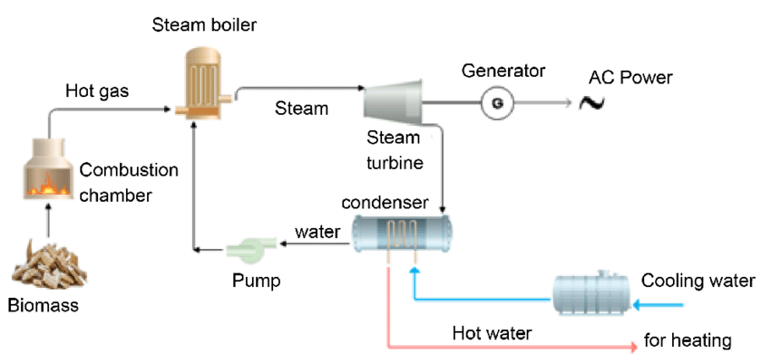
Sewage treatment plants (STPs) play a critical role in managing wastewater, but they also produce substantial amounts of waste heat during the treatment process. This heat, often considered a byproduct of operations, presents a valuable opportunity for energy recovery. Generating electricity from this waste heat not only reduces the energy costs of running sewage treatment plants but also contributes to sustainability by transforming waste into a usable resource. Below, we examine the various ways in which heat from sewage treatment plants can be harnessed for electricity generation and explore the benefits, challenges, and technologies involved.
a. Sources of Waste Heat in Sewage Treatment Plants
The sewage treatment process generates heat through various stages, including the physical, chemical, and biological treatment steps. Several key processes within a sewage treatment plant are particularly significant sources of heat:
- Aerobic Treatment (Activated Sludge Process): In this process, microorganisms are used to break down organic matter in wastewater, which produces heat as a byproduct of microbial activity. The aeration tanks, where oxygen is added to facilitate the microbial degradation of pollutants, also release a significant amount of heat.
- Anaerobic Digestion: During anaerobic digestion, sewage sludge is broken down by bacteria in the absence of oxygen. This process generates both methane (which can be used as a fuel) and heat. The heat produced in this stage can be harnessed for electricity generation.
- Sludge Dewatering: The mechanical processes used to dewater sludge, such as centrifuges or belt filter presses, also generate heat. This heat is often discarded, but it can be captured and used for power generation.
- Heat from Combined Heat and Power (CHP) Systems: Some sewage treatment plants already use combined heat and power (CHP) systems, which simultaneously generate electricity and thermal energy. These systems recover the heat from gas engines, turbines, or other sources within the plant, making them a valuable source of energy.
b. Technologies for Generating Electricity from Waste Heat in Sewage Treatment Plants
Several technologies can be employed to generate electricity from waste heat in sewage treatment plants, ranging from conventional heat recovery systems to more advanced techniques. These technologies can be used alone or in combination to optimize energy generation and improve efficiency.
- Organic Rankine Cycle (ORC): The Organic Rankine Cycle is one of the most common methods used to generate electricity from low- to medium-temperature heat sources. It operates similarly to a steam Rankine cycle, but instead of water, it uses an organic fluid with a lower boiling point. This makes ORC ideal for recovering heat from sewage treatment plants, where the temperature of the waste heat is typically in the range of 60°C to 120°C. The organic fluid is vaporized by the waste heat, driving a turbine or generator to produce electricity.
- Efficiency Considerations: ORC systems can operate effectively with waste heat from anaerobic digesters, aerobic treatment processes, and other stages of sewage treatment. The efficiency of ORC systems increases as the temperature of the waste heat rises, but it is still effective even with low-temperature sources.
- Kalina Cycle: The Kalina cycle is another advanced heat recovery technology that can be used in sewage treatment plants. It uses a mixture of water and ammonia as the working fluid, which has the advantage of a variable boiling point. This allows the system to be more efficient than conventional ORC systems, especially when the heat source has a wide temperature range. The Kalina cycle is particularly effective in scenarios where there is waste heat with temperatures that vary during the day or seasonally.
- Flexibility: The Kalina cycle can be adjusted to work with both higher and lower temperature waste heat sources, making it a versatile option for sewage treatment plants with varying thermal outputs.
- Thermoelectric Generators (TEGs): Thermoelectric generators are devices that convert heat directly into electricity through the thermoelectric effect. They are particularly useful for recovering waste heat from small or low-temperature sources. TEGs are compact, durable, and require minimal maintenance, making them a potential solution for sewage treatment plants that generate small amounts of waste heat or need distributed power generation.
- Applications: TEGs can be installed on smaller heat sources within a sewage treatment plant, such as heat exchangers or sludge dewatering equipment. They are also ideal for decentralized power generation, where the waste heat is distributed across different parts of the plant.
- Stirling Engines: Stirling engines are external combustion engines that operate by expanding and contracting a gas (usually helium or hydrogen) in a sealed cylinder. The temperature difference between the heat source and the cold side of the engine drives the engine’s mechanical motion, which is then converted into electricity. Stirling engines are highly efficient in converting low-temperature heat into mechanical energy and can be used to generate electricity in sewage treatment plants.
- High Efficiency at Low Temperatures: Stirling engines are suitable for waste heat recovery in sewage treatment plants because they can efficiently convert heat from a variety of temperatures, including those generated by biological processes like anaerobic digestion.
c. Benefits of Generating Electricity from Waste Heat in Sewage Treatment Plants
- Cost Reduction: One of the most significant benefits of generating electricity from waste heat is the reduction in operational costs for sewage treatment plants. By harnessing waste heat to produce electricity, plants can reduce their dependence on the grid, cutting electricity bills and improving energy self-sufficiency.
- Energy Efficiency: Utilizing waste heat for electricity generation improves the overall energy efficiency of the plant. Waste heat recovery systems allow sewage treatment plants to operate more sustainably by reducing energy waste and making better use of available resources.
- Reduced Carbon Footprint: By generating electricity from waste heat, sewage treatment plants can significantly lower their carbon emissions. This is especially true if the waste heat recovery system replaces the use of fossil fuels to generate electricity. For example, using methane from anaerobic digestion to power a CHP system can reduce the need for external power sources, leading to a reduction in greenhouse gas emissions.
- Renewable Energy Production: The heat generated by sewage treatment processes, especially methane produced in anaerobic digestion, is considered a renewable energy source. By capturing and utilizing this waste heat, sewage treatment plants contribute to the broader effort to transition to renewable energy and reduce reliance on fossil fuels.
- Resource Recovery: In addition to electricity generation, the heat recovered from sewage treatment plants can be used for other purposes, such as heating buildings, drying sludge, or supplying heat to nearby industries or district heating networks. This form of resource recovery adds additional value to the plant’s operations and makes the process more sustainable.
d. Challenges in Generating Electricity from Waste Heat in Sewage Treatment Plants
While generating electricity from waste heat in sewage treatment plants offers numerous benefits, there are challenges that need to be addressed:
- Capital Costs and Financing: The initial investment required to install waste heat recovery systems, especially advanced systems like ORC or Kalina cycles, can be high. For many sewage treatment plants, particularly those in developing regions or smaller municipalities, financing these systems can be a barrier. Financial incentives, grants, and low-interest loans can help mitigate these costs.
- Variability of Heat: Sewage treatment plants often experience fluctuations in the amount of waste heat produced depending on the season, time of day, and operational conditions. Designing systems that can handle this variability is essential for maintaining consistent electricity generation. Incorporating energy storage systems, such as thermal storage or batteries, can help smooth out fluctuations in heat availability.
- Operational and Maintenance Costs: Like any power generation system, waste heat recovery technologies require regular maintenance to ensure they continue to operate efficiently. While systems like ORC are relatively low-maintenance, other technologies such as Stirling engines or TEGs may require more frequent servicing. Plant operators need to factor in these ongoing operational costs.
- Efficiency at Lower Temperatures: As with many low-temperature waste heat sources, the efficiency of some heat recovery systems may be limited if the waste heat is not hot enough. Technologies like TEGs or Stirling engines can help address this issue, but optimizing energy recovery at lower temperatures remains a challenge for certain systems.
e. The Future of Waste Heat Recovery in Sewage Treatment Plants
As technologies continue to advance and awareness of sustainability increases, the future of generating electricity from waste heat in sewage treatment plants looks promising. Ongoing research and development are focused on improving the efficiency, scalability, and affordability of waste heat recovery systems, making them more accessible to a wider range of sewage treatment facilities.
The integration of renewable energy systems, such as solar or wind power, with waste heat recovery technologies could further reduce the environmental impact of sewage treatment plants and help them become even more energy self-sufficient. Additionally, expanding the use of microgrids and decentralized energy generation could enable sewage treatment plants to operate more independently and contribute to local energy grids.
With continued innovation, financial support, and government incentives, generating electricity from heat in sewage treatment plants could become a mainstream practice, contributing to both energy sustainability and effective wastewater management worldwide.
Conclusion
Generating electricity from waste heat in sewage treatment plants presents a unique opportunity to enhance the sustainability and efficiency of wastewater management. By leveraging heat recovery technologies like ORC, Kalina cycles, thermoelectric generators, and Stirling engines, plants can reduce their energy costs, lower their carbon footprint, and contribute to the growing demand for renewable energy sources. While challenges exist in terms of capital investment, system integration, and efficiency, the potential benefits of waste heat recovery are substantial, making it a promising solution for improving the sustainability of the global water and energy systems.
25. Policy and Regulatory Support for Generating Electricity from Waste Heat in Sewage Treatment Plants
For waste heat recovery systems to thrive in sewage treatment plants, strong policy and regulatory frameworks must be in place. These policies and regulations can play a key role in incentivizing the adoption of waste heat recovery technologies, ensuring their integration into plant operations, and providing the financial and technical support required to make these systems economically viable. Governments, utilities, and regulatory bodies must create the right environment for innovation in the energy recovery space while balancing environmental and economic priorities.
a. Financial Incentives and Subsidies
Governments can support the deployment of waste heat recovery technologies in sewage treatment plants through a variety of financial incentives and subsidies. These could include:
- Tax Credits and Deductions: Tax incentives, such as production tax credits or investment tax credits, can help reduce the upfront capital costs of implementing waste heat recovery systems. This is particularly important for smaller municipalities or facilities with limited budgets.
- Subsidies for Capital Investment: Direct subsidies can be provided to cover part of the initial investment costs for waste heat recovery technologies. Such subsidies can lower the financial barrier for sewage treatment plants, especially in areas where the costs of energy recovery technologies are perceived as prohibitively high.
- Grants for Research and Development: Governments can provide grants to support research and development (R&D) in waste heat recovery technologies, especially for improving efficiency at low temperatures, integrating renewable energy sources, or developing new materials for thermoelectric generators (TEGs). These grants can incentivize innovation and make waste heat recovery more accessible in the long term.
- Low-Interest Loans and Financing Programs: Governments and development banks can establish loan programs with favorable terms to finance the purchase and installation of waste heat recovery systems. Such programs would allow sewage treatment plants to implement these technologies while spreading the cost over several years.
b. Policy Frameworks for Waste Heat Utilization
In addition to financial incentives, strong policy frameworks are needed to support the use of waste heat in sewage treatment plants. These frameworks can promote energy efficiency, resource recovery, and waste heat utilization by aligning energy and water management policies.
- Energy Efficiency Standards: Governments can set energy efficiency standards for sewage treatment plants, mandating the recovery and utilization of waste heat in new and existing facilities. These standards could require plants to implement energy recovery measures or demonstrate a minimum percentage of energy recovery from waste heat as part of their operational certifications.
- Regulatory Support for Heat Recovery: Many regions have yet to develop clear regulations for the recovery and use of waste heat from industrial facilities. Regulatory frameworks that recognize waste heat as a valuable resource can incentivize its utilization in sewage treatment plants. These regulations could include allowances for the recovery of heat to produce electricity or reuse heat for internal purposes like sludge drying or heating buildings.
- Energy Sharing Agreements: Some sewage treatment plants are located near industrial complexes or urban centers. Policy support for energy sharing agreements can facilitate the distribution of electricity generated from waste heat to local power grids or neighboring industries. This could include creating mechanisms for power purchase agreements (PPAs) or long-term contracts with utilities or industrial consumers to sell the recovered electricity.
- Carbon Pricing and Emissions Reduction: Implementing carbon pricing or emissions trading schemes can create an economic incentive for sewage treatment plants to reduce their carbon footprint. Waste heat recovery is a proven method for reducing emissions, and plants that invest in these technologies could benefit from carbon credits or lower emissions penalties, making the investment more attractive.
c. Environmental Regulations and Sustainability Standards
Environmental regulations are critical for ensuring that waste heat recovery systems in sewage treatment plants are designed and operated in a way that minimizes their impact on the surrounding environment.
- Waste Heat Discharge Regulations: One challenge with waste heat recovery is that it is often necessary to discharge excess heat into nearby water bodies or the atmosphere. Environmental regulations can set limits on the temperature of discharges to prevent harm to local ecosystems. Implementing cooling technologies, such as closed-loop systems or heat exchangers, can help mitigate the environmental impact.
- Water Quality Standards: In some cases, sewage treatment plants may need to comply with strict water quality standards, which could require adjustments to waste heat recovery systems. These systems should be designed to ensure that the thermal impact of heat discharge does not exceed local temperature thresholds, which could negatively affect aquatic life.
- Sustainability Certification: Plant operators can be incentivized through certifications for sustainability and environmental performance. For example, wastewater treatment facilities that implement waste heat recovery systems could be awarded green certifications, demonstrating their commitment to energy efficiency and sustainability. This can enhance the reputation of the plant and encourage public and private investment.
- Public Awareness Campaigns: Regulatory agencies can support public awareness campaigns to highlight the environmental benefits of waste heat recovery systems in sewage treatment plants. By increasing knowledge about the role of sewage treatment plants in both wastewater management and energy recovery, regulators can foster broader acceptance of these technologies among the public, communities, and industries.
d. Challenges in Policy Implementation
Although there are clear advantages to adopting policies that support waste heat recovery in sewage treatment plants, several challenges must be addressed:
- Fragmented Regulatory Frameworks: In many regions, policies related to waste heat recovery are fragmented across different sectors—water, energy, environment, and waste management. A more integrated and cohesive policy framework is needed to promote waste heat recovery across these domains. Coordination between different regulatory bodies, industry stakeholders, and utilities is essential for creating a unified approach.
- Long-Term Policy Stability: The success of waste heat recovery projects depends on long-term policy stability. Changes in government or regulatory priorities can disrupt the financial incentives and regulatory frameworks that support these technologies. To ensure ongoing investment, policies should provide long-term certainty and consistency.
- Limited Market Penetration: While waste heat recovery is an emerging technology, it is still not widely adopted in many sewage treatment plants due to a lack of awareness and experience. Policymakers should focus on reducing knowledge gaps and promoting the successful case studies of plants that have successfully implemented waste heat recovery technologies.
- Balancing Investment Costs with Long-Term Benefits: Policymakers and industry leaders must address the challenge of balancing the high initial investment costs of waste heat recovery systems with their long-term environmental and economic benefits. Clear financial models and demonstration projects can help build confidence in the feasibility and sustainability of these technologies.
e. Future Directions in Policy Support for Waste Heat Recovery
In the future, it is likely that we will see more coordinated efforts at the international, national, and local levels to encourage waste heat recovery from sewage treatment plants and other industrial sources. Policy developments could include:
- Carbon Neutrality and Circular Economy Goals: As more governments commit to carbon neutrality and a circular economy, integrating waste heat recovery into sewage treatment operations will be a key part of achieving these goals. Policymakers will increasingly recognize the value of waste heat as a resource and will create comprehensive strategies for its recovery and utilization.
- Energy and Water Nexus Policies: Policies that focus on the interconnection between energy and water resources will gain more importance. Waste heat recovery can serve as a bridge between these two sectors by turning energy that would otherwise be wasted into a useful resource. This holistic approach will drive more sustainable development across both energy and water management industries.
- Global Standards and Best Practices: International standards and best practices for waste heat recovery in sewage treatment plants could be developed to encourage consistency in implementation across different regions. These standards would provide guidelines on the most effective technologies, operating procedures, and environmental considerations.
- Public-Private Partnerships (PPPs): Public-private partnerships will continue to play a significant role in the development and financing of waste heat recovery projects. By bringing together the resources and expertise of both the public and private sectors, PPPs can help facilitate the adoption of waste heat recovery technologies at a larger scale.
Conclusion
Policy and regulatory support are essential to enabling the widespread adoption of waste heat recovery technologies in sewage treatment plants. Financial incentives, clear regulatory frameworks, and environmental standards can all play a key role in driving innovation and implementation. With the right policies in place, sewage treatment plants can unlock the full potential of their waste heat, contributing to greater energy efficiency, reduced carbon emissions, and enhanced sustainability in the water and wastewater sectors. By combining technology, finance, and policy, the next generation of sewage treatment plants can become not just wastewater management facilities, but also critical players in the global transition to a sustainable and low-carbon energy future.
26. Case Studies of Waste Heat Recovery in Sewage Treatment Plants
Examining real-world examples of sewage treatment plants that have successfully implemented waste heat recovery systems can provide valuable insights into the practical challenges, benefits, and results of these technologies. By showcasing diverse applications across different regions and plant sizes, these case studies demonstrate how waste heat recovery can improve energy efficiency, reduce costs, and contribute to environmental sustainability.
a. Case Study 1: The London Thames Water Sewage Treatment Plant, United Kingdom
The London Thames Water Sewage Treatment Plant, one of the largest wastewater treatment facilities in Europe, has implemented a range of innovative technologies for waste heat recovery. The plant processes around 2.4 million cubic meters of wastewater per day, and its operations generate significant amounts of heat, particularly from anaerobic digestion and sludge treatment.
- Waste Heat Recovery Implementation: Thames Water has installed an ORC (Organic Rankine Cycle) system to recover heat from the anaerobic digesters. The system captures the waste heat generated by the microbial breakdown of organic matter in the digesters and converts it into electricity. This energy is then used to power the plant’s operations, reducing its reliance on external electricity sources.
- Energy Efficiency and Emissions Reduction: By recovering waste heat from the digestion process, the Thames Water plant generates enough electricity to power around 30% of its energy needs. This system has helped the plant reduce its carbon emissions and improve its overall energy efficiency. The plant also makes use of excess heat to dry sludge and provide heating for other areas of the facility, further enhancing resource recovery.
- Outcomes: Since the implementation of the ORC system, Thames Water has reduced its carbon footprint significantly. The plant has become a model of sustainable wastewater treatment, demonstrating how large-scale facilities can utilize waste heat for both electricity generation and process optimization. The project has also inspired similar initiatives in other parts of the United Kingdom and beyond.
b. Case Study 2: The Millau Sewage Treatment Plant, France
The Millau Sewage Treatment Plant, located in southern France, processes wastewater from a population of around 30,000 people. This smaller-scale facility sought to improve its sustainability by capturing and using waste heat from its operations.
- Heat Recovery from Anaerobic Digestion: Millau adopted a waste heat recovery strategy based on the heat produced by its anaerobic digesters. The digesters process organic sludge to produce biogas, which is burned to generate electricity. The process also produces substantial waste heat, which is captured and used to heat buildings and pre-heat incoming wastewater, improving the plant’s overall energy efficiency.
- Thermal Storage Integration: To maximize the use of recovered heat, the plant integrated a thermal storage system that stores excess heat during periods of low demand and releases it when needed. This system allows the plant to maintain consistent energy recovery despite variations in the heat output from the digesters.
- Outcomes: The waste heat recovery system has enabled Millau to reduce its energy costs by 40%, which has had a significant financial impact for a plant of its size. Additionally, by using waste heat for heating and preheating purposes, the plant has minimized its need for external energy sources, improving its overall sustainability.
c. Case Study 3: The Singapore Changi Water Reclamation Plant, Singapore
Singapore is known for its innovative approach to water management, and the Changi Water Reclamation Plant is no exception. The plant processes both domestic and industrial wastewater and has integrated waste heat recovery as part of its efforts to reduce energy consumption.
- Heat Recovery from Wastewater Treatment: The Changi Water Reclamation Plant incorporates a multi-stage treatment process that includes both aerobic and anaerobic treatment stages. The plant uses the waste heat generated during these processes, especially from the anaerobic digestion of sludge, to power turbines and generate electricity. This electricity is used to operate the plant’s own systems, such as pumps and motors, reducing the plant’s reliance on grid power.
- Integration with District Cooling: In addition to using waste heat for electricity generation, the Changi plant has explored district cooling systems. Heat captured from the treatment process is used to provide cooling to nearby facilities, such as office buildings and industrial complexes. This further improves energy efficiency by turning waste heat into a useful resource beyond the plant’s immediate needs.
- Outcomes: The Changi Water Reclamation Plant has been able to reduce its energy consumption by up to 40%, contributing significantly to the country’s goal of becoming a more sustainable city-state. The plant also serves as an example of how integrated water and energy management strategies can help urban centers reduce their environmental footprint.
d. Case Study 4: The Sedgefield Wastewater Treatment Plant, United States
Located in Sedgefield, North Carolina, the Sedgefield Wastewater Treatment Plant processes wastewater from around 10,000 residents. The facility has focused on incorporating renewable energy sources, including waste heat recovery, to improve its energy independence and reduce costs.
- Biogas and Heat Recovery: The plant generates biogas through the anaerobic digestion of sewage sludge. The biogas is burned in a combined heat and power (CHP) system, which produces both electricity and useful thermal energy. The excess heat from the CHP system is recovered and used to heat the digesters, as well as for building space heating.
- Energy Independence: The integration of waste heat recovery has allowed the Sedgefield plant to achieve a high degree of energy independence, with the facility now producing about 80% of its electricity needs through biogas and waste heat recovery. This has significantly reduced the plant’s electricity costs and reliance on the grid.
- Outcomes: As a result of these innovations, the Sedgefield Wastewater Treatment Plant has been able to significantly reduce its operating costs while improving sustainability. The use of waste heat to support the plant’s processes has helped reduce its overall energy consumption, with the added benefit of lowering greenhouse gas emissions.
e. Case Study 5: The Hong Kong Tai Po Sewage Treatment Works, Hong Kong
The Tai Po Sewage Treatment Works is one of Hong Kong’s largest sewage treatment facilities, processing the wastewater of over 300,000 residents. Given Hong Kong’s commitment to sustainability, the plant has been a pioneer in incorporating waste heat recovery technologies.
- Waste Heat from Anaerobic Digesters: Similar to other large facilities, Tai Po captures heat produced by its anaerobic digesters, where organic matter is broken down in the absence of oxygen. The heat is recovered and used to power ORC (Organic Rankine Cycle) systems that generate electricity for use throughout the facility.
- Heat Integration for Process Efficiency: The waste heat is also integrated into the facility’s overall thermal management system, helping to maintain optimal temperatures in key treatment areas. This process reduces the need for additional external energy inputs and helps keep the plant’s operations running efficiently.
- Outcomes: The Tai Po Sewage Treatment Works has achieved impressive results in terms of energy efficiency, reducing its electricity consumption and carbon emissions. The facility’s success has led to similar implementations in other sewage treatment plants across the region, contributing to Hong Kong’s broader sustainability goals.
f. Lessons Learned from Case Studies
Several key lessons can be drawn from these case studies, which can inform future waste heat recovery efforts in sewage treatment plants worldwide:
- Adaptability: Waste heat recovery technologies can be adapted to suit a variety of plant sizes and treatment processes. While larger facilities often benefit from ORC systems, smaller plants can still find success with simpler technologies such as CHP systems or thermoelectric generators (TEGs).
- Integration with Other Systems: Successful implementation often involves integrating waste heat recovery with other energy-saving technologies, such as biogas recovery, thermal storage, and district heating systems. This integration maximizes the value derived from waste heat and enhances overall energy efficiency.
- Long-Term Sustainability: The long-term sustainability of waste heat recovery projects depends on factors like regular maintenance, proper design for fluctuating heat availability, and the establishment of clear financial models. While initial investments can be high, the reduction in operating costs and improved energy self-sufficiency usually result in substantial long-term savings.
- Regulatory and Financial Support: Government policies and incentives play a critical role in enabling the success of waste heat recovery projects. Clear regulations, financial subsidies, and long-term energy policies that encourage energy efficiency can help plants overcome initial financial hurdles and ensure that energy recovery systems are implemented and maintained effectively.
Conclusion
These case studies demonstrate the versatility and effectiveness of waste heat recovery in sewage treatment plants. From large-scale facilities in the United Kingdom to smaller plants in North America, sewage treatment facilities worldwide are finding innovative ways to capture and use waste heat to generate electricity, reduce costs, and contribute to environmental sustainability. As technology advances and policy support increases, the potential for waste heat recovery in the water sector will continue to grow, offering further opportunities for energy efficiency, reduced carbon emissions, and a more sustainable future.
27. Generating Electricity Using Heat from Drying in Food Production
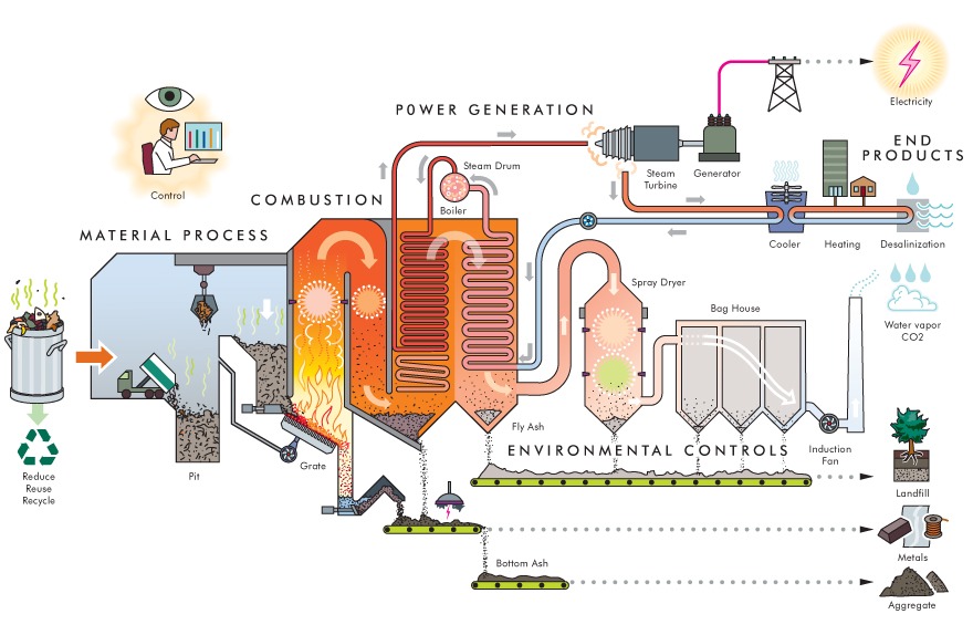
The food production industry, especially in processes like drying, is one of the largest energy-consuming sectors. Drying food products—such as fruits, vegetables, grains, meats, and dairy—requires significant heat energy to evaporate water from the raw materials. In many cases, the energy used in drying is not fully utilized, and a portion of it is lost to the environment as waste heat. However, advances in energy recovery technologies have made it possible to capture and convert this waste heat into electricity, improving the overall energy efficiency of food production facilities.
Waste heat recovery in food production can be used in various ways to generate electricity, reduce energy consumption, and decrease operating costs. This section explores how waste heat from drying processes can be recovered and transformed into useful electricity, offering a sustainable solution for the food industry.
a. Heat Sources in Food Drying
The drying process in food production typically involves the application of heat through methods such as:
- Hot Air Drying: In this process, warm air is circulated through the food to remove moisture. This is one of the most common methods used in food production, especially for drying fruits, vegetables, and grains.
- Freeze Drying: Freeze-drying involves freezing the food and then removing water by sublimation. This method is often used for delicate or high-value products, such as herbs, spices, and certain fruits.
- Spray Drying: In spray drying, liquid food is sprayed into a hot air chamber where the water evaporates, leaving behind powdered food products. This is commonly used for dairy products, soups, and juices.
- Solar Drying: Solar drying uses sunlight as the primary energy source, but even in solar drying systems, there can be significant residual heat.
While these methods require substantial energy input, they also generate large amounts of waste heat during the process. This heat can be captured and used for various purposes, including generating electricity.
b. Waste Heat Recovery Methods
To recover and convert the waste heat from food drying processes into electricity, various technologies can be applied:
- Organic Rankine Cycle (ORC):
- The ORC is one of the most efficient technologies for recovering low-temperature waste heat, typically in the range of 80–300°C. In the food production industry, ORC systems can recover heat from hot air dryers or exhaust gases from drying processes.
- How it works: The waste heat is used to heat a working fluid (such as an organic compound with a low boiling point), which vaporizes and drives a turbine connected to a generator. This mechanical energy is converted into electricity.
- Applications in Food Production: ORC systems are particularly effective for converting waste heat from hot air dryers in fruit and vegetable processing, as well as in grain drying operations.
- Thermoelectric Generators (TEGs):
- TEGs convert heat directly into electricity using the Seebeck effect, where a temperature difference across a thermoelectric material creates an electrical voltage. While TEGs are typically less efficient than ORC systems, they are simple to integrate into smaller systems.
- How it works: In a TEG system, heat from the drying process (such as from exhaust gases or heated surfaces) is applied to one side of the thermoelectric module. The resulting temperature gradient generates an electrical current, which can then be used to power sensors, lights, or small equipment within the plant.
- Applications in Food Production: TEGs are ideal for smaller-scale operations or where heat recovery needs to be done in a distributed fashion. For example, they could be used to power control systems or low-energy equipment in a food drying facility.
- Steam Rankine Cycle (SRC):
- The Steam Rankine Cycle (SRC) is another heat-to-power technology that can be used for recovering heat at higher temperatures (typically above 250°C). In SRC, waste heat is used to generate steam, which drives a steam turbine connected to a generator.
- How it works: Waste heat from a dryer is used to heat water, turning it into steam. The steam is then directed to a turbine, where its kinetic energy is converted into mechanical energy, which is then converted into electricity by a generator.
- Applications in Food Production: SRC is used in larger food production facilities where high-temperature heat recovery is required, such as in industrial-scale drying processes for powdered milk, juices, and sauces.
- Heat Recovery Ventilation Systems (HRV):
- These systems are designed to capture heat from exhaust air or ventilation systems and recycle it to pre-heat incoming air. While HRVs themselves do not directly generate electricity, they can reduce the overall energy consumption of a drying system, indirectly supporting electricity generation from waste heat recovery technologies.
- How it works: Heat from the exhaust air stream is transferred to the incoming fresh air via a heat exchanger. This reduces the need for additional heating, lowering energy demand and improving the efficiency of the drying process.
- Applications in Food Production: HRVs are widely used in food drying facilities, particularly in drying rooms where large amounts of hot air are used. These systems can significantly reduce energy consumption in facilities where heat recovery alone cannot generate sufficient power.
c. Applications and Benefits of Waste Heat Recovery in Food Drying
- Energy Efficiency Improvement:
- By recovering and utilizing waste heat from drying processes, food production plants can significantly reduce their energy consumption. The recovered electricity can be used to power other parts of the plant, such as refrigeration, lighting, or packaging operations, reducing the reliance on grid power.
- Cost Savings:
- The recovered electricity can directly lower operational costs, particularly for energy-intensive drying processes. By capturing waste heat and converting it into electricity, food production plants can offset some of their energy costs, improving their overall financial performance.
- Environmental Impact Reduction:
- Reducing reliance on conventional energy sources helps lower the carbon footprint of the food production process. Waste heat recovery technologies contribute to sustainability goals by reducing greenhouse gas emissions associated with fossil fuel-based electricity generation.
- Additionally, by improving energy efficiency, the overall environmental impact of the drying process is minimized.
- Enhancing Product Quality:
- In some cases, capturing and reusing waste heat can also help improve product quality. For example, by stabilizing temperature conditions during drying, it is possible to achieve more consistent moisture levels, preventing over-drying or under-drying of food products, which can affect texture, flavor, and shelf life.
- Scalability:
- Waste heat recovery systems are highly scalable and can be implemented in small-scale artisanal food production operations as well as in large industrial facilities. Whether it’s a small fruit drying operation or a large-scale grain processing facility, waste heat recovery technologies can be tailored to meet specific energy demands.
- Compliance with Energy Regulations:
- Many countries have set regulations requiring industries to reduce their energy consumption and improve sustainability. By integrating waste heat recovery technologies, food producers can comply with these regulations, avoiding penalties and improving their market competitiveness.
d. Challenges and Considerations
While waste heat recovery from drying in food production offers numerous benefits, there are also challenges and considerations that need to be addressed:
- Capital Investment:
- The initial investment in waste heat recovery technologies can be substantial, especially for more complex systems like ORC or Steam Rankine Cycle. The financial feasibility of such systems depends on factors such as plant size, heat availability, and energy savings.
- Heat Source Variability:
- The temperature and consistency of waste heat can fluctuate depending on production rates and the type of drying process used. This variability can make it challenging to design a waste heat recovery system that operates efficiently across different production conditions. Accurate modeling and monitoring are necessary to ensure optimal performance.
- Integration with Existing Systems:
- Integrating waste heat recovery into existing food production plants can be complex, especially in older facilities. Retrofitting a plant with heat recovery technologies may require significant modifications to the infrastructure and operational practices, adding both time and cost to the implementation process.
- Maintenance and Operation:
- Waste heat recovery systems, particularly those that convert heat to electricity, require ongoing maintenance to ensure they operate efficiently. This includes regular monitoring of heat exchangers, turbines, and other components to prevent downtime and ensure optimal performance.
e. Future Directions and Innovations
- Advanced Thermoelectric Materials:
- Research into new thermoelectric materials with higher efficiency could make TEGs a more attractive option for small-scale food drying facilities. Advances in material science could help improve the performance of TEGs, making them more viable for a wider range of applications in the food industry.
- Hybrid Systems:
- Combining different heat recovery systems could provide even greater efficiencies. For example, integrating ORC and TEG technologies in parallel could allow food production facilities to capture both high- and low-temperature waste heat, maximizing energy recovery.
- Automation and Monitoring:
- With the rise of Industry 4.0 technologies, food production facilities will increasingly adopt smart systems to monitor and optimize energy usage. Automated systems could monitor the efficiency of waste heat recovery processes, adjusting them in real-time to maximize electricity generation and energy savings.
- Policy and Incentives:
- Governments and regulatory bodies can play a crucial role in encouraging the adoption of waste heat recovery technologies in the food production industry. Policies that incentivize energy recovery—such as tax credits, grants, or subsidies—can make it easier for food producers to implement these technologies and reduce their environmental impact.
Conclusion
Generating electricity from waste heat in food drying processes presents a promising opportunity for improving energy efficiency and sustainability in the food production sector. By capturing and converting waste heat into electricity, food producers can reduce energy consumption, lower costs, and enhance environmental sustainability. As technology continues to evolve, the potential for waste heat recovery in food production will only grow, helping to create a more energy-efficient and environmentally responsible food industry.
28. Case Studies of Waste Heat Recovery in Food Drying
Examining real-world applications of waste heat recovery in food drying processes provides valuable insights into how these technologies work in practice, the challenges involved, and the benefits achieved. Below are several case studies that highlight successful waste heat recovery in food production, particularly in drying operations.
a. Case Study 1: The Fruit Drying Facility, Spain
In Spain, a fruit drying company specializing in dried apricots and figs sought to reduce its energy consumption and improve its sustainability. The drying process used hot air circulating in large dehydrators, which generated significant amounts of waste heat.
- Heat Recovery Implementation: The facility installed an Organic Rankine Cycle (ORC) system to recover waste heat from the exhaust air of the dryers. The ORC system captures heat from the dryer exhausts, converts it into electricity, and uses it to power the plant’s auxiliary systems, such as conveyors, pumps, and lighting.
- Energy Efficiency and Cost Savings: By recovering heat from the drying process, the company reduced its reliance on external energy sources, covering about 25% of the plant’s electricity needs. The system also decreased the plant’s overall energy consumption, leading to lower operating costs.
- Outcomes: After the ORC system was installed, the facility saw a reduction in energy bills by approximately 20%. Additionally, the company improved its sustainability profile by reducing carbon emissions and increasing its competitiveness in a market increasingly focused on environmentally friendly production practices.
b. Case Study 2: Dairy Powder Production, Australia
In Australia, a dairy processing plant that produces milk powder and other dairy products sought ways to reduce its energy consumption, particularly in the drying stage, which involved spray drying milk.
- Heat Recovery from Spray Dryers: The plant implemented a heat recovery system that captured hot air from the spray drying process. The waste heat was used to preheat the incoming milk and provide additional thermal energy for other production processes, such as pasteurization and cleaning.
- Energy Conversion and Electricity Generation: The recovered heat was also used in a small ORC system, which converted low-temperature waste heat into electricity to power the plant’s operations. The system generated approximately 15% of the plant’s total energy needs.
- Outcomes: The implementation of the heat recovery system led to a significant reduction in energy consumption, particularly by lowering the demand for steam and electricity from external sources. The plant also improved its overall operational efficiency and reduced its carbon footprint by utilizing renewable waste heat.
- Further Impacts: The project was recognized for its innovation in energy management and helped the company comply with stringent environmental regulations set by the Australian government. The success of the project has inspired similar efforts in other dairy production facilities in the region.
c. Case Study 3: Tomato Processing Facility, Italy
A tomato processing plant in Italy, specializing in producing concentrated tomato paste, sought to reduce energy costs associated with the drying of tomato paste and other by-products. The facility used hot air drying for concentration and had high heat losses during the process.
- Heat Recovery Integration: The plant installed a combined heat and power (CHP) system, utilizing biogas produced from the fermentation of tomato waste. The CHP system recovered the heat from this biogas combustion and used it to power an ORC unit that generated electricity.
- Utilizing Exhaust Heat: In addition to the CHP system, the facility also employed a heat exchanger system to recover and redirect excess heat from drying chambers back into the drying process, improving energy efficiency and reducing the need for additional heating.
- Energy Savings and Environmental Benefits: The integration of waste heat recovery systems resulted in a 30% reduction in energy consumption. By generating electricity onsite, the plant became less reliant on grid power, and the CHP system also provided useful byproducts such as hot water for cleaning and process heating.
- Sustainability and Cost Efficiency: This project allowed the facility to reduce its carbon emissions by approximately 18%, contributing to the plant’s sustainability goals. Furthermore, the significant reduction in energy costs helped the plant improve its profitability.
d. Case Study 4: Grain Drying Facility, United States
In the United States, a large-scale grain drying facility focused on improving the energy efficiency of its operations, particularly during the fall harvest when drying demand was highest. Grain drying requires large amounts of heat, and the facility was looking for ways to recover energy from this process.
- Heat Recovery System: The plant installed a system that captured waste heat from the exhaust air of the grain dryers. This system utilized heat exchangers to recover and transfer heat to the incoming air supply, pre-heating it before it entered the dryer.
- Additional Energy Recovery with TEGs: In addition to the heat exchangers, the plant deployed thermoelectric generators (TEGs) to convert lower-temperature exhaust heat into electricity. This system generated small but consistent amounts of power to help run smaller systems within the facility, such as control panels and lighting.
- Energy Efficiency Gains: The heat recovery system and TEGs together contributed to a 20% reduction in energy consumption, particularly during peak drying periods when energy demand was high. The plant reduced its reliance on natural gas for heating, leading to lower fuel costs.
- Outcomes and Scalability: The success of this project demonstrated the potential for smaller-scale operations to implement waste heat recovery. The facility’s implementation of low-cost heat recovery technologies has since served as a model for other grain drying facilities looking to reduce energy costs.
e. Case Study 5: Spice Drying, India
In India, a spice processing plant specializing in the drying of various spices, such as chili and turmeric, faced high energy costs associated with the hot air drying process. The drying process was inefficient, with much of the heat being lost to the atmosphere, leading to increased energy use and higher production costs.
- Implementing Heat Recovery: The facility installed an energy recovery system that captured the heat from the exhaust air of the drying units. This recovered heat was used to preheat the incoming air supply to the drying units, significantly reducing the need for additional fuel to maintain required drying temperatures.
- Electricity Generation via ORC: The plant also installed an ORC system to convert the medium-temperature waste heat into electricity. This electricity was used to power lighting, fans, and other systems in the plant, reducing the need for grid electricity.
- Economic and Environmental Benefits: The plant saw a reduction in energy consumption by approximately 25%, leading to a decrease in fuel costs. In addition, the electricity generation from waste heat reduced reliance on the local power grid, lowering the plant’s carbon footprint.
- Long-term Sustainability: The plant’s use of waste heat recovery helped it become more energy-independent, contributing to the long-term sustainability of operations. The project also highlighted the benefits of waste heat recovery in smaller-scale food production facilities in developing countries.
f. Key Takeaways and Insights from Case Studies
These case studies highlight several key insights that can be applied to other food drying facilities looking to implement waste heat recovery technologies:
- Energy Efficiency Gains: Across all case studies, waste heat recovery consistently led to significant energy savings, ranging from 15% to 30%. This underscores the potential for waste heat recovery to improve the energy efficiency of food production processes, particularly in energy-intensive operations like drying.
- Diverse Applications: Waste heat recovery can be applied to a wide variety of food drying processes, including those for fruits, grains, spices, and dairy products. The success of waste heat recovery technologies is not limited to large-scale operations; smaller plants can also benefit from relatively simple systems like heat exchangers or thermoelectric generators.
- Environmental and Cost Benefits: The implementation of waste heat recovery systems not only reduces energy consumption but also provides environmental benefits by lowering carbon emissions. Furthermore, by reducing reliance on external energy sources, food producers can significantly lower their operating costs.
- Technology Integration: In many cases, the success of waste heat recovery systems depends on integrating multiple technologies, such as combining ORC with heat exchangers or thermoelectric generators. A holistic approach that considers various types of waste heat and optimizes their use can yield the best results.
- Scalability and Flexibility: Waste heat recovery technologies can be scaled to suit different plant sizes and types of food production. While large-scale facilities may benefit from more complex systems like ORC or Steam Rankine Cycle, smaller operations can effectively use simpler technologies like heat exchangers or TEGs.
- Regulatory and Financial Support: Government incentives, such as tax credits or subsidies for energy-efficient technologies, can play a key role in helping food producers overcome initial capital investment barriers. Many of these projects have been supported by grants or favorable regulatory policies that encourage sustainability in the food industry.
Conclusion
The case studies discussed demonstrate the significant potential for waste heat recovery in food drying operations, providing a win-win solution for food producers seeking to improve energy efficiency, reduce costs, and enhance sustainability. By leveraging waste heat recovery technologies such as ORC systems, heat exchangers, and thermoelectric generators, food producers can not only meet environmental standards but also realize substantial financial benefits. As technology continues to evolve, these systems will become more accessible and efficient, further driving the adoption of energy-saving practices in the global food production industry.
29. Challenges and Opportunities in Scaling Waste Heat Recovery in Food Drying
While waste heat recovery from food drying processes offers numerous advantages, several challenges need to be overcome before these technologies can be more widely adopted across the food industry. Understanding these challenges, as well as the opportunities they present, is crucial for driving the integration of waste heat recovery in food production on a larger scale. This section explores the challenges faced by food producers and the opportunities for advancing waste heat recovery systems.
a. Challenges in Waste Heat Recovery for Food Drying
- Capital Cost and Investment:
- One of the most significant barriers to the widespread adoption of waste heat recovery systems in food drying is the upfront capital cost. Technologies like ORC systems, Steam Rankine Cycle (SRC), and combined heat and power (CHP) systems require substantial investment. The high initial cost can be a deterrent for smaller food producers, especially those with limited budgets.
- Solution: The development of more cost-effective technologies and modular systems designed specifically for smaller food production facilities could make waste heat recovery more accessible. Additionally, government incentives or grants to support energy efficiency projects could help offset initial costs and make these technologies more financially viable.
- Integration with Existing Infrastructure:
- Many food production plants, particularly older facilities, were not designed with waste heat recovery in mind. Retrofitting existing infrastructure with waste heat recovery systems can be complex and costly. The need to redesign or replace certain components, such as ventilation systems, heat exchangers, and boilers, can add to the difficulty.
- Solution: Engineers and system designers can focus on creating flexible waste heat recovery systems that can be integrated with a wide range of existing food processing equipment. Using modular or plug-and-play solutions could help reduce the complexity and cost of retrofitting older facilities.
- Heat Source and Consistency:
- Waste heat sources in food drying processes can vary significantly in terms of temperature, flow rate, and consistency. Drying processes such as spray drying, freeze drying, and hot air drying generate waste heat with varying characteristics, making it challenging to design a single system that can handle all scenarios effectively.
- Solution: Advanced monitoring and control systems could be employed to track heat source variability in real time, allowing systems to adjust dynamically for optimal performance. Additionally, hybrid systems that can handle both high- and low-temperature waste heat, like combined ORC and thermoelectric systems, could be more adaptable to fluctuating conditions.
- Operational and Maintenance Costs:
- While waste heat recovery systems can reduce long-term energy costs, they often come with their own maintenance and operational expenses. Regular monitoring, maintenance of heat exchangers, turbines, and thermoelectric modules are required to ensure these systems function efficiently.
- Solution: Predictive maintenance technologies, such as IoT sensors and machine learning algorithms, can be used to monitor system performance in real time and predict when maintenance is required. This proactive approach can help minimize downtime and extend the lifespan of the equipment.
- System Complexity and Operational Knowledge:
- Implementing and operating advanced waste heat recovery systems requires specialized knowledge and expertise. Food production facilities may not have the in-house expertise to operate, maintain, and optimize these systems effectively, leading to potential inefficiencies or system failures.
- Solution: Food production plants could partner with external contractors or service providers who specialize in waste heat recovery systems. Additionally, training and capacity building programs could be introduced to ensure that plant operators are familiar with the technology and its maintenance needs.
- Space and Installation Constraints:
- Many food production facilities, especially smaller ones, have limited space available for the installation of waste heat recovery equipment. Installing large-scale systems, such as ORC units or CHP plants, may require significant floor space and could disrupt the existing workflow.
- Solution: Designing compact, modular waste heat recovery systems that can be installed in limited space or as part of a phased expansion plan could make it easier for food producers to adopt these technologies. Systems that can be integrated into the existing infrastructure with minimal disruption would likely be more appealing.
- Regulatory and Policy Barriers:
- In some regions, regulatory barriers and outdated energy efficiency standards may hinder the adoption of waste heat recovery systems. In many cases, energy regulations focus more on emissions reduction and energy conservation than on the reuse of waste heat, which can make it difficult for producers to justify the implementation of these technologies.
- Solution: Policymakers and regulatory bodies should work to create clear guidelines that encourage waste heat recovery technologies in food production. Policies that incentivize renewable energy production, offer tax credits, or provide subsidies for energy-efficient technologies would be critical to overcoming these barriers.
b. Opportunities for Scaling Waste Heat Recovery in Food Drying
- Technological Advancements and Cost Reduction:
- One of the greatest opportunities in scaling waste heat recovery in food drying lies in technological innovation. The development of more efficient, compact, and cost-effective systems can make waste heat recovery more accessible and affordable for a wider range of food producers.
- Opportunity: Advances in thermoelectric materials, improved ORC systems, and innovative heat exchangers could reduce costs and improve efficiency. As technology continues to evolve, the return on investment (ROI) for waste heat recovery systems is likely to improve, making them more attractive to small and medium-sized food producers.
- Decentralized and Small-Scale Solutions:
- Not all food production facilities require large-scale waste heat recovery systems. Smaller-scale, decentralized solutions that capture waste heat from specific equipment, such as drying chambers or ovens, could provide significant energy savings without the need for major infrastructure changes.
- Opportunity: Developing scalable, modular systems that can be easily adapted to different production environments could help make waste heat recovery a viable option for smaller operations. For example, compact ORC units or thermoelectric generators could be installed in small or artisanal food processing plants, allowing them to benefit from waste heat recovery.
- Energy-as-a-Service (EaaS) Models:
- Energy-as-a-Service (EaaS) models, where companies pay for energy recovery and management services rather than purchasing the equipment outright, could provide an attractive financing option for food producers. This model could lower the upfront cost of installing waste heat recovery systems while offering long-term savings.
- Opportunity: EaaS providers could offer waste heat recovery solutions on a subscription or pay-per-performance basis. This model could help reduce the financial risk associated with investing in these technologies, particularly for small or medium-sized food producers who may lack capital for large investments.
- Circular Economy and Sustainability:
- Waste heat recovery fits perfectly into the principles of the circular economy, which focuses on minimizing waste and maximizing resource efficiency. By capturing and reusing waste heat, food producers can create more sustainable operations that generate less waste and use less energy.
- Opportunity: By promoting circular economy principles, food producers can gain a competitive edge in markets that value sustainability. Additionally, waste heat recovery could be integrated with other waste management strategies, such as converting organic waste into biogas for energy, further enhancing overall resource efficiency.
- Smart Technology and Automation:
- The integration of smart technology and automation in waste heat recovery systems can optimize performance, reduce energy consumption, and increase the operational lifespan of the systems. Real-time monitoring of heat sources, system performance, and energy output could significantly improve the efficiency of waste heat recovery technologies.
- Opportunity: Implementing advanced sensors, IoT devices, and data analytics platforms can help automate the operation of waste heat recovery systems, ensuring that they run optimally and require minimal intervention. Additionally, machine learning algorithms could predict heat recovery patterns and adjust system settings to maximize energy efficiency.
- Partnerships and Collaborative Efforts:
- Food production facilities can collaborate with technology providers, energy service companies, and academic institutions to further research and develop new waste heat recovery solutions. Collaborative efforts could lead to the development of more efficient systems tailored specifically to the food industry’s needs.
- Opportunity: Partnerships between food producers and energy technology developers could accelerate the adoption of waste heat recovery systems. Sharing knowledge and resources can lead to the creation of cost-effective solutions that meet the industry’s energy demands while improving sustainability.
- Market Demand for Sustainable Products:
- Increasing consumer demand for sustainably produced food products provides a compelling business case for food producers to invest in energy-efficient technologies like waste heat recovery. The market trend is shifting towards eco-friendly products, with consumers becoming more conscious of the environmental impact of food production.
- Opportunity: Food producers can leverage waste heat recovery systems as a way to promote their sustainability efforts. This not only helps reduce operating costs but also positions the company as a leader in environmentally responsible food production, which can be a strong selling point in the market.
Conclusion
While there are challenges to scaling waste heat recovery in food drying operations, the opportunities presented by technological advancements, decentralized solutions, and financial models like Energy-as-a-Service offer significant potential. By overcoming barriers such as capital cost, integration with existing infrastructure, and operational complexity, food producers can unlock substantial energy savings, reduce costs, and enhance sustainability. As the industry continues to embrace energy-efficient solutions, waste heat recovery will play an increasingly important role in the future of food production, helping companies meet both economic and environmental goals.
30. Generating Electricity Using Waste Heat from Brewing Beer
The brewing process, like many industrial operations, generates a significant amount of waste heat, particularly during the boiling, fermentation, and drying stages. For breweries looking to enhance their energy efficiency, capturing and utilizing this waste heat offers a viable solution to reduce energy consumption and lower operational costs. This section explores the methods and technologies available for generating electricity from waste heat in the brewing industry.
a. Sources of Waste Heat in the Brewing Process
The brewing process involves several stages, each generating excess heat that can be captured for energy recovery. Key stages where waste heat is typically produced include:
- Boiling of the Wort: The wort, which is the liquid extracted from the mashed malted barley, is boiled during the brewing process to sterilize it and extract hops’ flavors. This boiling generates significant heat, which is often dissipated into the atmosphere or lost through ventilation systems.
- Fermentation: Fermentation, the process in which yeast converts sugars into alcohol, generates both heat and carbon dioxide. The exothermic nature of fermentation leads to elevated temperatures, often requiring cooling systems to maintain optimal fermentation conditions.
- Hot Water Production: The brewery uses hot water for various processes, such as mashing and sanitization. The water that exits these processes is typically hot and could be reused for energy generation.
- Drying of Hops and Barley: During the malting and drying processes, significant heat is used to dry the grains and hops. This waste heat could be recovered and redirected for other uses, including electricity generation.
- Chilling: Cooling systems that are used to bring the beer to the right fermentation or storage temperatures release waste heat, which can also be captured for use.
b. Technologies for Waste Heat Recovery in Brewing
There are several technologies that can be used to recover and convert waste heat from the brewing process into electricity. These technologies primarily focus on capturing heat from low-to-medium temperature sources and converting it into useful power.
- Organic Rankine Cycle (ORC):
- Working Principle: ORC systems are designed to convert low-temperature heat (typically below 300°C) into electricity. In the case of brewing, ORC can be used to recover waste heat from the boiling wort, fermentation process, or hot water systems.
- How It Works: ORC systems use an organic working fluid with a lower boiling point than water, allowing it to vaporize at lower temperatures. This vapor drives a turbine connected to a generator, producing electricity. The ORC system can work effectively with temperatures between 80°C and 300°C, which are common in the brewing process.
- Example: A brewery could use the heat from the wort boiling stage to power the ORC system, which could then generate electricity to power pumps, lights, and other low-energy equipment on-site.
- Steam Rankine Cycle (SRC):
- Working Principle: Similar to ORC, the Steam Rankine Cycle (SRC) is a thermodynamic cycle that converts heat energy into mechanical power. SRC systems are used when the waste heat source has a higher temperature, typically over 150°C. It works by using steam as the working fluid to drive a turbine.
- How It Works: The waste heat from boiling or other high-temperature stages in brewing can be used to generate steam, which is then passed through a turbine to generate electricity.
- Example: A brewery with excess heat from the hot water or boiling process could install an SRC system to generate electricity to run various equipment, including pumps, compressors, and even the refrigeration system.
- Combined Heat and Power (CHP) Systems:
- Working Principle: CHP systems, also known as cogeneration systems, produce both heat and electricity from a single energy source. In a brewery, CHP can be implemented by capturing waste heat from the brewing process and using it for electricity generation while simultaneously providing heat for various processes, such as heating water, sterilization, and fermentation.
- How It Works: A CHP system can burn biomass (such as spent grains), natural gas, or biogas produced on-site to generate both heat and power. The heat can be recovered to maintain brewing temperatures, while the electricity can be used to power the brewery’s operations.
- Example: Many breweries utilize spent grains from the brewing process as a biomass fuel for a CHP system. This system recovers the waste heat to provide hot water and steam for brewing, while the electricity generated can help reduce reliance on the grid.
- Thermoelectric Generators (TEGs):
- Working Principle: Thermoelectric generators (TEGs) use the Seebeck effect to convert temperature differences directly into electrical voltage. TEGs are often used for small-scale waste heat recovery applications, making them suitable for capturing heat from localized sources in the brewing process.
- How It Works: TEGs can be applied to small, high-temperature differentials between the waste heat source and ambient temperature. For example, heat from fermenters or cooling systems can be absorbed by TEGs, which then convert the thermal energy into electricity.
- Example: In a brewery, TEGs could be used on smaller heat sources like exhaust fans or cooling systems. These generators are typically more effective for smaller-scale operations, making them a cost-effective choice for microbreweries.
- Heat Exchanger Systems:
- Working Principle: While heat exchangers do not directly generate electricity, they play a critical role in the energy recovery process. Heat exchangers capture heat from exhaust air, hot water, and other waste streams and transfer it to incoming water or air, reducing the need for external heating and improving energy efficiency.
- How It Works: A heat exchanger can be integrated into the brewery’s heating and cooling systems to preheat water or air before it enters the system, reducing the amount of external energy required for heating. This, in turn, decreases overall energy costs and can be paired with other electricity-generating systems like ORC or SRC.
- Example: In a brewery, a heat exchanger can be used to preheat the incoming air or water before it enters the boiler or mash tun. This reduces the energy demand for heating, and by coupling it with an ORC or SRC system, it can indirectly contribute to generating electricity.
c. Benefits of Waste Heat Recovery in Brewing
- Energy Efficiency and Cost Savings:
- By recovering waste heat and converting it into electricity, breweries can reduce their reliance on external power sources, leading to significant cost savings. The recovered heat can also be reused for brewing processes like boiling or fermentation, further reducing the need for purchased energy.
- Sustainability and Environmental Impact:
- The brewing industry is energy-intensive, and the adoption of waste heat recovery technologies can help reduce the overall carbon footprint of breweries. By generating electricity from waste heat, breweries can decrease their dependence on fossil fuels, thus reducing greenhouse gas emissions.
- Energy Independence:
- Waste heat recovery provides breweries with a degree of energy independence by reducing their reliance on grid electricity. This can be particularly beneficial in regions with volatile energy prices or unreliable electricity grids.
- Improved Process Control and Operational Efficiency:
- The integration of waste heat recovery systems like ORC or CHP allows breweries to control their energy production and consumption more efficiently. This improves overall process control and ensures a steady supply of electricity to critical systems like refrigeration, pumps, and lighting.
- Utilizing Byproducts:
- Waste heat recovery systems, especially CHP systems, can allow breweries to utilize byproducts such as spent grains and other organic waste. This biomass can be converted into biogas or directly burned for energy generation, turning waste into a valuable resource.
- Enhanced Competitiveness:
- As sustainability becomes a key factor in consumer choices, breweries that adopt energy-efficient technologies and reduce their environmental impact can improve their marketability. Companies with a strong sustainability profile may also be eligible for green certifications or government incentives.
d. Challenges of Implementing Waste Heat Recovery in Brewing
- Initial Capital Investment:
- The installation of waste heat recovery systems, particularly ORC or SRC, can be expensive due to the need for specialized equipment and system integration. While the long-term savings can offset these initial costs, breweries may face financial barriers in adopting these technologies.
- System Complexity and Maintenance:
- Waste heat recovery systems require ongoing monitoring and maintenance. ORC, CHP, and SRC systems in particular involve sophisticated technology that may require specialized staff or third-party support for efficient operation.
- Availability of Suitable Heat Sources:
- Not all brewing processes produce waste heat at temperatures high enough to justify the installation of advanced waste heat recovery systems like ORC or SRC. Breweries need to assess whether their waste heat streams are of the right temperature and volume to make the investment worthwhile.
- Integration with Existing Operations:
- The integration of waste heat recovery systems into existing brewery operations can require significant modifications to the brewing process, infrastructure, or equipment. This can be disruptive and costly, particularly in older breweries with less flexible infrastructure.
e. Future Trends and Opportunities
- Advances in Thermoelectric Technology:
- As thermoelectric materials improve, TEGs may become more efficient and cost-effective for small-scale applications in brewing. This would open up waste heat recovery opportunities for microbreweries and smaller-scale operations that may not be able to invest in larger ORC or SRC systems.
- Smart Brewery Systems:
- The future of waste heat recovery in brewing may involve smart systems that automatically adjust the operation of heat recovery technologies based on real-time data. IoT sensors and advanced analytics can optimize energy use, reduce waste, and predict maintenance needs.
- Circular Economy and Sustainability Initiatives:
- As the brewing industry embraces circular economy principles, breweries will continue to look for ways to minimize waste, reduce energy consumption, and enhance sustainability. Waste heat recovery will play an increasingly important role in this trend, particularly as breweries seek to turn waste into a valuable resource.
Conclusion
Breweries, whether large or small, generate significant amounts of waste heat during the brewing process. By adopting waste heat recovery technologies such as Organic Rankine Cycle (ORC), Steam Rankine Cycle (SRC), Combined Heat and Power (CHP) systems, or Thermoelectric Generators (TEGs), breweries can significantly reduce their energy costs, improve operational efficiency, and minimize their environmental impact. While challenges such as initial investment costs and system complexity exist, the long-term benefits make waste heat recovery an attractive option for breweries looking to embrace sustainability and energy efficiency. As technology advances, the opportunities for breweries to generate electricity from waste heat will continue to expand, making these systems an integral part of the future of brewing.
31. Economic and Financial Considerations for Implementing Waste Heat Recovery in Brewing
While the technological and environmental benefits of waste heat recovery in brewing are clear, breweries must also carefully consider the economic and financial aspects of adopting these systems. Understanding the costs, potential savings, and return on investment (ROI) is essential for breweries evaluating the feasibility of waste heat recovery technologies. This section outlines the key financial considerations for breweries interested in integrating waste heat recovery systems into their operations.
a. Capital Costs and Investment Considerations
- Initial Investment in Equipment:
- The upfront capital costs of installing waste heat recovery systems like Organic Rankine Cycle (ORC), Steam Rankine Cycle (SRC), or Combined Heat and Power (CHP) systems can be substantial. These systems require specialized equipment, such as turbines, heat exchangers, and generators, which can be expensive. The complexity of the installation process and the need to integrate these systems into existing brewery infrastructure can further increase costs.
- For smaller breweries or those with limited capital, the initial investment might seem prohibitive. However, larger breweries that produce significant volumes of beer may be better positioned to absorb the costs of these systems due to their higher energy consumption and greater potential for savings.
- Retrofitting Existing Systems:
- Many breweries, particularly those that have been in operation for several years, may need to retrofit their existing infrastructure to accommodate waste heat recovery technologies. Retrofitting involves upgrading or replacing components like heating systems, cooling systems, and electrical wiring to integrate the new technology. This can increase the overall cost of installation.
- However, the long-term savings and the ability to capture waste heat that would otherwise be lost can make retrofitting a worthwhile investment. In some cases, smaller, modular systems may be used to minimize the disruption and cost of retrofitting.
b. Operational and Maintenance Costs
- Ongoing Maintenance and Monitoring:
- Waste heat recovery systems, especially ORC and CHP units, require regular maintenance to ensure efficient operation. Components like turbines, heat exchangers, and electrical systems need periodic inspections, cleaning, and replacements of parts to avoid breakdowns and optimize performance.
- The maintenance costs can vary depending on the complexity of the system and the level of automation in place. Breweries will need to budget for ongoing maintenance, as well as the cost of replacing parts or making repairs when necessary.
- However, some breweries may choose to outsource the maintenance of their waste heat recovery systems to specialized service providers, which could help reduce the burden on in-house staff and ensure the systems are maintained by experts.
- Energy Management and Optimization:
- Efficient operation of waste heat recovery systems requires real-time monitoring of energy production and consumption. This may involve the installation of energy management systems or advanced sensors that track heat flow, electrical output, and system performance.
- Some breweries may choose to invest in advanced energy management systems that use data analytics to optimize energy usage and maximize the amount of waste heat recovered. The upfront cost of these systems could be high, but the potential for improved energy efficiency and greater cost savings over time could justify the investment.
c. Financial Incentives and Support
- Government Incentives and Subsidies:
- In many regions, governments offer financial incentives, grants, or tax breaks to businesses that adopt energy-efficient technologies like waste heat recovery systems. These incentives can significantly reduce the upfront costs of installing these systems and improve the overall financial viability of the project.
- Some countries have set ambitious sustainability targets and offer incentives to encourage industries, including brewing, to reduce their carbon footprint and improve energy efficiency. By taking advantage of these programs, breweries can lower their financial barriers to entry and speed up the ROI period for waste heat recovery systems.
- Green Certifications and Market Advantage:
- Adopting energy-efficient technologies like waste heat recovery can help breweries achieve green certifications, such as LEED (Leadership in Energy and Environmental Design) or ISO 50001 (energy management systems). These certifications can provide a marketing advantage by showcasing the brewery’s commitment to sustainability.
- Consumers are increasingly drawn to companies that prioritize environmental responsibility, and breweries that adopt waste heat recovery may be able to command premium prices for their products or tap into niche markets that value sustainability.
- In some cases, green certifications or sustainability achievements may also open up access to additional funding opportunities or loans with favorable terms, as well as access to eco-conscious investors or partnerships.
- Financing Models:
- Breweries that are hesitant to invest in waste heat recovery systems due to the high initial costs may explore alternative financing models, such as leasing or Power Purchase Agreements (PPAs). In a leasing arrangement, a third-party provider would install the waste heat recovery system and allow the brewery to pay a monthly fee for its use, reducing the upfront capital requirement.
- PPAs are another option, where a third-party investor installs and maintains the waste heat recovery system in exchange for a long-term contract that guarantees a fixed payment or a share of the electricity savings over a set period. These financing models allow breweries to generate energy savings without the need for substantial upfront capital investment.
d. Return on Investment (ROI) and Payback Period
- Energy Savings:
- The primary financial benefit of waste heat recovery is the reduction in energy costs. By recovering waste heat and converting it into electricity, breweries can reduce their reliance on external power sources, lowering their energy bills. In some cases, breweries can achieve energy savings of 20-40% or more, depending on the scale of the operation and the efficiency of the heat recovery system.
- Additionally, using recovered heat for heating, cooling, or process applications can further reduce the brewery’s energy consumption and decrease costs associated with purchasing fuel or electricity from the grid.
- Payback Period:
- The payback period for a waste heat recovery system refers to the time it takes for the energy savings to offset the initial capital investment. Breweries typically seek a payback period of 3-5 years for energy-efficient technologies like waste heat recovery systems, although the actual payback period can vary depending on factors such as system size, energy prices, and local incentives.
- Larger breweries with higher energy consumption may achieve a quicker payback period, while smaller breweries may have a longer payback period due to the lower volume of energy that can be recovered. Breweries in areas with higher energy prices or favorable incentives may also see a faster return on investment.
- Long-Term Savings:
- Although the initial investment may be high, the long-term savings provided by waste heat recovery systems can make the investment worthwhile. Over the lifetime of the system, which can often exceed 10-15 years, breweries can save a substantial amount on energy costs. This long-term financial benefit can significantly improve the brewery’s bottom line and help the business become more competitive in a challenging market.
- Cost of Inaction:
- For breweries that do not adopt waste heat recovery technologies, the cost of inaction should also be considered. As energy costs continue to rise and environmental regulations become stricter, breweries that fail to invest in energy-efficient technologies may face higher operating costs and regulatory compliance challenges in the future. Conversely, adopting waste heat recovery systems can help future-proof breweries against rising energy prices and potential regulatory changes.
e. Potential Economic Impact on Brewery Profitability
- Reduced Operating Expenses:
- By recovering and reusing waste heat, breweries can significantly reduce their operating expenses related to energy. Energy is one of the largest operational costs for breweries, particularly in energy-intensive processes like brewing, boiling, and cooling. Lower energy costs can directly improve profitability by reducing the overhead associated with these processes.
- Competitive Pricing:
- Waste heat recovery systems allow breweries to lower their operating costs and potentially pass on the savings to consumers through more competitive pricing. A brewery that reduces its energy expenses can offer lower prices while maintaining profitability, giving it an edge in the competitive beer market.
- Boosting Profit Margins:
- Energy efficiency improvements directly impact the profit margin. The cost savings achieved by adopting waste heat recovery systems can be reinvested into other areas of the business, such as marketing, expansion, or new product development, further enhancing the brewery’s growth potential and financial stability.
- New Revenue Streams:
- Some breweries may even explore selling excess electricity generated by waste heat recovery systems back to the grid. In regions where net metering is allowed, breweries can offset their energy consumption by supplying power to the utility, generating an additional revenue stream.
Conclusion
Generating electricity from waste heat in the brewing industry presents significant economic and financial opportunities. By reducing energy costs, improving energy efficiency, and leveraging financial incentives, breweries can see substantial savings and a quick return on investment. While the initial capital investment and operational costs can be substantial, the long-term financial benefits, including energy savings, market advantages, and sustainability initiatives, make waste heat recovery an attractive option for breweries looking to enhance profitability and reduce their environmental footprint. With the right financing strategies and the adoption of the latest technologies, breweries can successfully integrate waste heat recovery systems into their operations and realize long-term economic gains.
32. Future Trends and Innovations in Waste Heat Recovery for Brewing
As breweries continue to explore ways to improve sustainability and reduce operational costs, the field of waste heat recovery is evolving rapidly. Technological advancements, changes in market dynamics, and emerging environmental policies are driving innovation in waste heat recovery systems. This section highlights some of the key trends and innovations that are shaping the future of waste heat recovery in the brewing industry.
a. Advanced Materials for Thermoelectric Generators (TEGs)
- Improved Efficiency:
- Thermoelectric generators (TEGs) are emerging as a promising technology for waste heat recovery, particularly in small-scale applications. However, the efficiency of traditional TEGs has been limited by the materials used. New research into advanced thermoelectric materials, such as nanomaterials, graphene, and advanced semiconductors, is improving the efficiency of TEGs.
- These materials can potentially increase the electrical output of TEGs, making them more viable for breweries that produce moderate to low amounts of waste heat. With better efficiency, TEGs could become more widespread in microbreweries, where small amounts of waste heat are available but are insufficient for larger-scale systems like ORC or CHP.
- Flexible and Scalable Designs:
- Innovations in material science are also leading to more flexible and scalable TEG designs. This means breweries of all sizes, from craft brewers to larger operations, can implement TEG-based waste heat recovery solutions that are tailored to their specific needs. Flexible TEGs can be integrated into existing brewery systems without significant disruption to ongoing operations.
- Scalable designs allow breweries to start small and gradually expand their waste heat recovery capacity as their energy needs grow or as they experience savings that justify the further investment.
b. Hybrid Waste Heat Recovery Systems
- Combination of Technologies:
- Hybrid systems, which combine multiple waste heat recovery technologies, are becoming increasingly popular. For example, a brewery may use an Organic Rankine Cycle (ORC) system to capture high-temperature waste heat, while simultaneously using a Thermoelectric Generator (TEG) or a Stirling engine to recover lower-temperature heat from fermentation or cooling processes.
- Hybrid systems take advantage of the complementary strengths of different technologies, providing more efficient energy recovery across a broader range of waste heat sources. By capturing both high and low-temperature waste heat, breweries can maximize energy recovery and improve overall efficiency.
- Integration with Other Renewable Energy Systems:
- As sustainability becomes a more prominent goal for breweries, hybrid waste heat recovery systems can also be integrated with other renewable energy sources, such as solar, wind, or biomass. By combining waste heat recovery with these renewable technologies, breweries can further reduce their carbon footprint, lower energy costs, and become more energy self-sufficient.
- For instance, a brewery might use its waste heat recovery system to power an ORC, while solar panels generate additional electricity during the day to supplement the brewery’s energy needs. This integration could also help stabilize energy supply by reducing reliance on the grid during peak hours.
c. Artificial Intelligence (AI) and Internet of Things (IoT) for Energy Optimization
- Smart Energy Management Systems:
- The integration of artificial intelligence (AI) and the Internet of Things (IoT) into waste heat recovery systems is paving the way for smarter energy management. AI-based algorithms can analyze real-time data from energy systems to optimize the performance of waste heat recovery units, ensuring that energy recovery is maximized at all times.
- IoT sensors embedded throughout a brewery’s waste heat recovery systems can provide detailed insights into temperature changes, flow rates, and energy consumption patterns. These sensors can transmit data to centralized control systems, where AI algorithms can predict energy demand, adjust system operations, and identify areas for efficiency improvements.
- Predictive Maintenance:
- With the integration of AI and IoT technologies, predictive maintenance systems are becoming more common in waste heat recovery systems. Using real-time data, AI can monitor the condition of system components, such as turbines, heat exchangers, and pumps, and predict when maintenance or repairs are needed. This helps avoid costly downtime and unplanned maintenance while ensuring that waste heat recovery systems operate at peak efficiency.
- Predictive maintenance also helps breweries reduce operational costs by extending the life of their waste heat recovery systems and reducing the frequency of repairs.
d. Adoption of Energy-as-a-Service (EaaS) Models
- Outsourcing Energy Management:
- The Energy-as-a-Service (EaaS) model is an emerging business model that allows breweries to outsource energy management to specialized third-party providers. In this model, the provider installs and manages waste heat recovery systems, providing the brewery with energy savings in return for a monthly service fee or a share of the savings.
- This model removes the financial burden of high initial capital costs and allows breweries, especially smaller ones, to benefit from waste heat recovery technologies without taking on the risk or responsibility of system maintenance. EaaS providers can offer performance guarantees, ensuring that breweries achieve the expected energy savings.
- Data-Driven Energy Optimization:
- In an EaaS model, the third-party provider uses advanced data analytics to continuously monitor the brewery’s energy usage and identify areas for further optimization. Energy savings from waste heat recovery systems can be tracked and reported, and the provider can make real-time adjustments to ensure maximum efficiency. This allows breweries to focus on their core operations while ensuring that energy efficiency remains at the forefront of their energy strategy.
e. Carbon Capture and Utilization (CCU) Integration
- Reducing Emissions from Brewing:
- Carbon capture and utilization (CCU) is gaining traction as a complementary technology to waste heat recovery in the brewing industry. Breweries are increasingly focused on reducing their carbon emissions, and CCU can help capture CO2 emissions from fermentation processes and turn them into useful byproducts, such as synthetic fuels or chemicals.
- Integrating CCU with waste heat recovery systems can help breweries achieve near-zero emissions. For example, waste heat could be used to power CO2 capture systems, while the captured carbon could be reused in the production of green chemicals or used as a feedstock for algae biofuels.
- Circular Economy Models:
- The combination of waste heat recovery and CCU systems aligns with the growing emphasis on the circular economy, where waste products are seen as valuable resources rather than byproducts. By using waste heat to power CCU systems, breweries can close the loop on energy and carbon emissions, making their operations more sustainable and reducing their overall environmental impact.
f. Policy and Regulatory Developments
- Stricter Environmental Regulations:
- Governments around the world are setting increasingly strict environmental regulations and sustainability targets for industries, including brewing. These regulations often include energy efficiency standards, emissions limits, and carbon footprint reductions. Breweries that adopt waste heat recovery systems may be better equipped to meet these regulations, ensuring compliance and avoiding penalties.
- By implementing waste heat recovery systems, breweries can also demonstrate their commitment to corporate social responsibility and sustainability, which may improve their reputation with consumers, investors, and regulatory bodies.
- Carbon Credits and Emission Reduction Programs:
- As carbon pricing and cap-and-trade programs become more widespread, breweries that adopt waste heat recovery technologies may be eligible to earn carbon credits for reducing their carbon emissions. These credits can be sold to other businesses looking to offset their emissions, providing an additional revenue stream for breweries.
- Participation in emission reduction programs not only helps breweries financially but also supports their sustainability initiatives, aligning their operations with global efforts to combat climate change.
g. The Role of Industry Collaboration and Research
- Collaborative Innovation:
- The brewing industry is increasingly collaborating with research institutions, technology providers, and sustainability-focused organizations to accelerate the development and adoption of waste heat recovery technologies. These collaborations often result in the creation of tailored solutions that address the unique challenges faced by breweries of all sizes.
- Industry associations, such as the Brewers Association and the European Brewery Convention, are playing a key role in promoting best practices for energy efficiency, facilitating knowledge sharing, and helping breweries stay ahead of the curve when it comes to adopting new technologies.
- R&D into New Heat Recovery Techniques:
- Ongoing research into new materials, processes, and systems is expected to yield even more efficient and cost-effective waste heat recovery solutions for the brewing industry. For example, researchers are exploring the potential of advanced heat pump systems, which could capture and upgrade low-grade waste heat to higher temperatures, making it suitable for electricity generation or process heating.
Conclusion
The future of waste heat recovery in the brewing industry is bright, with innovations and emerging technologies driving greater energy efficiency, sustainability, and profitability. Advanced materials, hybrid systems, AI and IoT integration, and new business models are reshaping the landscape of waste heat recovery, making it more accessible and efficient for breweries of all sizes. By staying ahead of these trends and adopting cutting-edge technologies, breweries can further reduce their environmental impact, improve energy efficiency, and enhance their bottom line. The evolving nature of waste heat recovery offers exciting opportunities for breweries to future-proof their operations, increase their competitiveness, and contribute to a more sustainable global economy.
33. Generating Electricity using Heat from the Textile Dyeing Industry
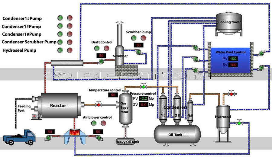
The textile dyeing industry is a highly energy-intensive sector that consumes significant amounts of energy during its processes, especially during the dyeing and drying phases. These processes generate large amounts of waste heat, much of which is often discarded into the environment. However, this waste heat can be harnessed to generate electricity through various heat recovery technologies, thus improving energy efficiency, reducing costs, and minimizing environmental impacts. In this section, we explore the potential of generating electricity using waste heat from the textile dyeing industry.
a. Waste Heat Generation in the Textile Dyeing Industry
- Key Processes Generating Heat:
- Dyeing Process: The textile dyeing process, particularly in batch dyeing and continuous dyeing, involves the use of hot water or steam to heat the fabric. These processes consume large amounts of thermal energy, and much of it is lost through exhaust gases, hot wastewater, or in the cooling systems.
- Drying Process: After dyeing, fabrics typically undergo drying, which requires additional energy in the form of heat. The drying process, which can be done using hot air or steam, is another significant source of waste heat that can be recovered.
- Finishing Process: Finishing processes, such as heat setting, curing, and pressing, also release substantial amounts of heat, especially in thermosetting and heat curing operations, where high temperatures are used to bond the dye to the fabric.
- Types of Waste Heat:
- High-Temperature Waste Heat: High-temperature waste heat (above 250°C) is typically found in steam systems or drying processes. This type of waste heat can be recovered using technologies like Organic Rankine Cycle (ORC) systems, which convert the heat into electricity.
- Medium-Temperature Waste Heat: Moderate temperatures (100°C to 250°C) are found in air dryers, steam condensates, and exhaust gases from the dyeing process. Heat exchangers and heat pumps can capture and repurpose this heat for either heating processes within the plant or generating electricity.
- Low-Temperature Waste Heat: Low-grade heat (below 100°C) is often found in cooling systems, wastewater, or ventilated air streams. While challenging to recover for electricity generation, it can be utilized in low-temperature applications or used to preheat water for other processes, reducing overall energy consumption.
b. Technologies for Generating Electricity from Waste Heat
- Organic Rankine Cycle (ORC):
- Overview: The ORC is one of the most commonly used technologies for converting medium to high-temperature waste heat into electricity. The ORC operates on a similar principle to the steam turbine but uses organic fluids with lower boiling points than water. This makes it effective at capturing heat from processes like dyeing, which often operate at temperatures below the boiling point of water.
- Application in Textile Dyeing: In the textile dyeing industry, ORC systems can be installed to recover waste heat from exhaust gases or steam condensates. These systems capture the heat, convert it into mechanical energy through turbines, and then generate electricity that can be used within the plant or exported to the grid.
- Benefits: The ORC is highly efficient for capturing and converting waste heat into electricity, with the ability to operate at lower temperatures than traditional steam cycles. It can significantly reduce a textile dyeing plant’s reliance on grid electricity and decrease operational costs.
- Steam Rankine Cycle (SRC):
- Overview: The SRC is another thermodynamic cycle used for recovering high-temperature waste heat. This system is similar to the ORC but operates with water or steam as the working fluid. It is particularly effective for industries with high-temperature waste heat, such as the textile dyeing industry.
- Application in Textile Dyeing: High-temperature steam used in the dyeing process can be fed into an SRC system, where it drives a steam turbine to generate electricity. This electricity can power various operations within the dyeing plant, reducing reliance on external energy sources.
- Benefits: The SRC is a well-established and reliable technology for high-temperature waste heat recovery. It is suitable for larger textile dyeing plants with high steam consumption, where the scale of operations justifies the installation of an SRC system.
- Heat Exchangers and Heat Pumps:
- Heat Exchangers: Heat exchangers can recover waste heat from exhaust gases, wastewater, or cooling water streams. By transferring the heat to incoming fluids (e.g., water or air), the waste heat can be reused for process heating or preheating water for dyeing and finishing operations.
- Heat Pumps: Heat pumps are particularly useful for recovering low-grade heat (below 100°C). They work by transferring heat from low-temperature sources to higher-temperature systems. In the textile dyeing industry, heat pumps can be used to recover waste heat from cooling systems, such as cooling towers or air conditioning systems, and then upgrade this heat for use in heating water or drying processes.
- Thermoelectric Generators (TEGs):
- Overview: Thermoelectric generators (TEGs) convert heat directly into electricity by exploiting the Seebeck effect, where a temperature difference between two materials generates an electric current. Although not as commonly used in large-scale systems as ORC or SRC, TEGs are gaining attention due to their compact size, scalability, and potential for low-temperature waste heat recovery.
- Application in Textile Dyeing: TEGs can be installed to capture low- to medium-temperature heat from exhaust gases, steam condensates, or other heat sources in the dyeing process. These systems are particularly suitable for smaller-scale textile dyeing operations or for providing electricity for specific needs within the plant.
- Benefits: TEGs are compact, modular, and relatively low-maintenance, making them ideal for decentralized electricity generation in smaller textile facilities. They are also capable of recovering waste heat from low-temperature sources, which might be difficult for other technologies to handle.
c. Economic and Environmental Benefits
- Reduced Energy Costs:
- Waste heat recovery systems in the textile dyeing industry can significantly reduce energy costs by generating electricity from otherwise wasted heat. This helps lower the dependence on grid electricity, which is often expensive, particularly in regions with high energy prices.
- By using waste heat to power energy-intensive processes such as dyeing, drying, and finishing, textile dyeing plants can achieve a more stable and predictable energy cost structure, leading to improved profitability.
- Improved Sustainability:
- The textile dyeing industry is known for its high energy consumption and environmental impact. By recovering and reusing waste heat, companies can reduce their overall carbon footprint. The reduction in energy consumption also reduces the need for fossil fuels, contributing to lower greenhouse gas emissions.
- Waste heat recovery technologies also help textile dyeing plants comply with increasingly stringent environmental regulations, as many countries are implementing policies to reduce industrial emissions and improve energy efficiency.
- Return on Investment (ROI):
- The ROI for waste heat recovery systems in the textile dyeing industry can vary depending on factors like the size of the plant, the amount of waste heat generated, and local energy prices. However, the typical payback period for systems such as ORC or SRC is between 3 to 5 years, making them a relatively quick and cost-effective solution.
- Smaller textile operations may find thermoelectric generators (TEGs) or heat pumps more accessible, as these systems generally require lower initial capital investment and can be scaled according to need.
- Energy Independence:
- Waste heat recovery allows textile dyeing plants to become more energy self-sufficient by generating their own electricity. This reduces the plant’s vulnerability to energy price fluctuations and potential supply disruptions, providing a more reliable and secure energy supply.
d. Challenges and Considerations
- Capital Investment:
- The initial capital investment required for waste heat recovery systems can be high, particularly for large-scale installations like ORC or SRC systems. However, this can be offset by long-term energy savings and potential incentives or subsidies offered by governments for energy-efficient technologies.
- Smaller operations may find the capital costs of heat pumps or TEGs more manageable, allowing for gradual implementation of waste heat recovery systems over time.
- Maintenance and Operational Complexity:
- Waste heat recovery systems, particularly ORC and SRC, require ongoing maintenance to ensure optimal performance. Regular inspections, cleaning, and repairs are necessary to prevent system failure and maintain energy generation efficiency.
- The complexity of these systems may require specialized training for plant operators or the hiring of external service providers, which could add to operating costs.
- Temperature Range and System Compatibility:
- Not all textile dyeing processes generate heat at temperatures that are suitable for all types of waste heat recovery systems. For example, TEGs are more effective at recovering low- to medium-temperature heat, while ORC systems require higher temperatures.
- Ensuring compatibility between the available waste heat and the selected recovery technology is crucial for achieving efficient energy recovery. In some cases, hybrid systems that combine multiple technologies may be necessary to capture a broader range of waste heat.
- Space Requirements:
- Installing waste heat recovery systems, particularly larger ORC or SRC units, may require significant space within the plant. Smaller operations with limited space may need to consider more compact systems like TEGs or heat pumps, which can be installed without significant disruption to existing operations.
e. Future Trends and Innovations
- Integration with Circular Economy Models:
- As the textile industry shifts toward more sustainable practices, there is increasing interest in circular economy models, where waste products are minimized, and resources are reused. Waste heat recovery fits into this model by turning discarded energy into a valuable resource, reducing the environmental impact of textile dyeing.
- Additionally, the integration of waste heat recovery with water recycling systems could create a closed-loop process, where both heat and water are efficiently reused, further improving sustainability in textile production.
- Smart Energy Management:
- The future of waste heat recovery in the textile dyeing industry lies in the integration of smart energy management systems. These systems will use data analytics, AI, and IoT technologies to monitor energy flows, optimize energy usage, and improve the efficiency of heat recovery systems.
- Smart sensors and real-time monitoring could help detect inefficiencies or potential issues in the waste heat recovery process, enabling faster responses and proactive maintenance to ensure maximum performance.
Conclusion
Generating electricity from waste heat in the textile dyeing industry offers significant opportunities for cost savings, sustainability, and energy efficiency. By utilizing waste heat recovery technologies like ORC, SRC, heat pumps, and TEGs, textile manufacturers can reduce their reliance on grid electricity, lower their carbon footprint, and improve their bottom line. While there are challenges associated with capital investment and system complexity, the long-term benefits, including reduced energy costs and improved environmental compliance, make waste heat recovery an attractive investment for the textile dyeing industry. With advancements in technology and an increasing focus on sustainability, the adoption of waste heat recovery systems is poised to play a key role in the future of the textile industry.
34. Generating Electricity using Waste Heat from the Rubber and Plastics Industry
The rubber and plastics industry generates substantial amounts of waste heat during manufacturing processes like extrusion, molding, and vulcanization. This waste heat is often released into the environment, contributing to inefficiency and environmental degradation. However, this heat can be captured and repurposed to generate electricity, thereby improving the overall energy efficiency of these processes and reducing the plant’s energy consumption. In this section, we explore how waste heat from the rubber and plastics industry can be harnessed for electricity generation.
a. Waste Heat Generation in Rubber and Plastics Manufacturing
- Key Processes Generating Heat:
- Vulcanization: Vulcanization is a key process in rubber production, where raw rubber is heated with sulfur to improve its elasticity, strength, and durability. This process typically requires high temperatures, which result in significant amounts of waste heat that can be recovered.
- Extrusion: The extrusion process, where heated raw plastic or rubber is forced through molds to create various products, also generates substantial waste heat. The molten material is heated to high temperatures during extrusion, and much of this energy is lost to the surrounding environment.
- Injection Molding: In injection molding, raw plastic is melted and injected into molds to form finished products. The heating of the plastic material during this process releases waste heat, which can be recovered and used for electricity generation.
- Compounding: Compounding is a process in which various materials, such as rubber, plastic, and additives, are mixed together. This process generates heat, which can be captured and converted into useful energy.
- Types of Waste Heat:
- High-Temperature Waste Heat: High-temperature heat (above 250°C) is often generated during processes like vulcanization or extrusion. This type of heat can be recovered using technologies such as the Organic Rankine Cycle (ORC), which is designed to convert high-temperature waste heat into electricity.
- Medium-Temperature Waste Heat: Medium temperatures (100°C to 250°C) are typically found in exhaust gases or cooling systems. This heat can be recovered using heat exchangers and heat pumps, or in some cases, converted into electricity through ORC or steam Rankine cycles.
- Low-Temperature Waste Heat: Low-grade heat (below 100°C) is often available from cooling systems and exhaust streams. While this is challenging to recover for electricity generation, it can be used for heating purposes or to preheat incoming materials, thus improving the overall energy efficiency of the plant.
b. Technologies for Generating Electricity from Waste Heat
- Organic Rankine Cycle (ORC):
- Overview: The ORC is a proven technology for recovering and converting medium- to high-temperature waste heat into electricity. The system uses an organic fluid with a lower boiling point than water, allowing it to operate effectively at lower temperatures.
- Application in Rubber and Plastics: ORC systems can be deployed in rubber and plastics manufacturing plants to recover heat from extrusion, vulcanization, or injection molding processes. This recovered heat is used to generate mechanical power via a turbine, which is then converted into electricity.
- Benefits: The ORC system is efficient in converting waste heat into electricity, and it is especially effective at capturing heat from processes that operate at temperatures lower than the boiling point of water. This allows for significant energy savings and reduced reliance on external electricity sources.
- Steam Rankine Cycle (SRC):
- Overview: The SRC is a thermodynamic cycle used to convert high-temperature steam into mechanical energy, which is then used to generate electricity. The process works by using heat to generate steam, which drives a turbine that is connected to an electrical generator.
- Application in Rubber and Plastics: Steam generated during the vulcanization process or other high-temperature operations can be fed into an SRC system to drive a turbine. The electricity generated can power operations in the plant, reducing the need for grid power.
- Benefits: SRC systems are widely used and reliable, offering good efficiency in larger rubber and plastics manufacturing plants where high-temperature waste heat is abundant. It is an established method for electricity generation from waste heat.
- Heat Exchangers and Heat Pumps:
- Heat Exchangers: Heat exchangers can capture waste heat from various processes, such as exhaust gases or cooling water, and transfer this heat to other fluids that need heating. In rubber and plastics manufacturing, this can be used to preheat water or air for use in other parts of the production process, or in some cases, the heat can be used directly to generate electricity.
- Heat Pumps: Heat pumps are effective at recovering low- to medium-temperature heat (below 100°C). These systems work by transferring heat from a lower temperature source, such as exhaust air or cooling water, to a higher-temperature system where the heat can be used for process heating or converted into electricity.
- Benefits: Heat exchangers and heat pumps are highly versatile and can be applied in various parts of a rubber or plastics plant. They are particularly beneficial for capturing lower-grade waste heat and increasing the overall energy efficiency of the plant.
- Thermoelectric Generators (TEGs):
- Overview: TEGs convert waste heat directly into electricity by exploiting the Seebeck effect. When there is a temperature difference between two materials, an electric current is generated. TEGs are particularly useful for small-scale electricity generation from low-temperature heat sources.
- Application in Rubber and Plastics: TEGs can be used in rubber and plastics plants to recover heat from exhaust gases, cooling systems, or other waste heat sources. The electricity generated can power smaller processes or serve as supplemental power for plant operations.
- Benefits: TEGs are compact, reliable, and require minimal maintenance. They are well-suited for smaller operations and can be easily integrated into existing systems to capture low-grade waste heat and generate electricity.
c. Economic and Environmental Benefits
- Reduced Energy Costs:
- One of the primary benefits of waste heat recovery in the rubber and plastics industry is a reduction in energy costs. By capturing and repurposing waste heat to generate electricity, plants can reduce their reliance on external electricity sources, leading to significant savings on energy bills.
- The amount of energy saved depends on the scale of operations and the amount of waste heat generated, but even small plants can benefit from the use of heat recovery technologies.
- Improved Sustainability:
- The rubber and plastics industry is known for its high energy consumption and environmental impact. By recovering and using waste heat, plants can reduce their overall carbon footprint and improve their environmental performance. This can be especially important for companies aiming to comply with increasingly stringent environmental regulations.
- Waste heat recovery technologies also help reduce the amount of heat released into the environment, which can contribute to better air quality and a reduction in the local heat island effect, particularly in industrial areas.
- Return on Investment (ROI):
- The ROI for waste heat recovery systems can vary depending on the scale of the rubber and plastics plant, the amount of waste heat generated, and local energy prices. In larger operations, ORC or SRC systems can have payback periods of 3 to 5 years, making them attractive investments.
- Smaller plants or operations with limited space may find thermoelectric generators or heat pumps more suitable due to their lower capital cost and scalability.
- Energy Independence:
- By generating electricity from waste heat, rubber and plastics manufacturing plants can reduce their dependence on grid electricity. This provides greater energy security and stability, as well as reducing vulnerability to energy price fluctuations and supply disruptions.
d. Challenges and Considerations
- Capital Investment:
- The initial capital investment for waste heat recovery systems can be significant, especially for large-scale technologies like ORC or SRC. However, these costs can be offset by long-term energy savings and potential tax incentives or government subsidies for energy-efficient systems.
- Smaller systems like TEGs and heat pumps may require less upfront investment, making them more suitable for smaller or medium-sized operations.
- Maintenance and Operational Complexity:
- Waste heat recovery systems require regular maintenance to ensure they operate efficiently. ORC and SRC systems, in particular, require specialized knowledge and skills for operation and maintenance.
- Operators may need to be trained to monitor and maintain the systems effectively, or third-party service providers may be needed for ongoing support.
- Space Requirements:
- Larger waste heat recovery systems, such as ORC or SRC, require significant space for installation. Rubber and plastics plants with limited space may need to consider smaller, more compact systems or explore ways to integrate the systems without disrupting production.
- Heat exchangers and heat pumps typically have smaller footprints and may be easier to retrofit into existing facilities.
- Temperature Range and System Compatibility:
- Not all rubber and plastics manufacturing processes generate waste heat at temperatures suitable for all types of waste heat recovery systems. For example, TEGs are more effective for low-temperature heat, while ORC and SRC systems are better for higher temperatures.
- Ensuring that the waste heat temperature matches the system requirements is crucial for maximizing energy recovery.
e. Future Trends and Innovations
- Hybrid Systems:
- Future developments in waste heat recovery could involve the integration of hybrid systems that combine different technologies. For example, combining ORC and heat pumps could enable more efficient capture and conversion of a wider range of temperatures, making waste heat recovery more accessible and effective for different types of operations.
- Integration with Industry 4.0:
- The integration of waste heat recovery systems with smart manufacturing and Industry 4.0 technologies could improve system efficiency. Advanced sensors, real-time monitoring, and data analytics can optimize heat recovery processes, increase energy savings, and predict maintenance needs before problems arise.
- Sustainability and Circular Economy:
- As the rubber and plastics industry continues to focus on sustainability and reducing environmental impact, waste heat recovery systems will play a vital role in advancing circular economy principles. By recovering waste heat, plants can minimize energy consumption, reduce emissions, and operate in a more sustainable manner.
Conclusion
The rubber and plastics industry generates substantial waste heat during manufacturing processes, much of which is often discarded. By capturing and converting this heat into electricity, manufacturers can reduce energy costs, improve sustainability, and enhance their energy independence. Technologies like Organic Rankine Cycle (ORC), Steam Rankine Cycle (SRC), heat exchangers, heat pumps, and thermoelectric generators (TEGs) can effectively capture and convert waste heat into useful energy. While the initial investment and maintenance costs may be significant, the long-term benefits, including energy savings, improved environmental performance, and a quick return on investment, make waste heat recovery an attractive solution for the rubber and plastics industry. With continued innovation and integration with emerging technologies, waste heat recovery systems will become an increasingly important part of the industry’s shift toward more sustainable and energy-efficient operations.
35. Generating Electricity using Heat from the Pharmaceutical Industry
The pharmaceutical industry is energy-intensive, with significant heat generation occurring during the manufacturing of drugs, chemical synthesis, and sterilization of equipment and materials. This heat is often released as waste into the environment, leading to energy inefficiencies. However, through the recovery of waste heat from pharmaceutical processes, it is possible to generate electricity, reducing energy consumption and enhancing the sustainability of the industry. This section delves into how waste heat from the pharmaceutical industry can be harnessed for electricity generation.
a. Waste Heat Generation in Pharmaceutical Manufacturing
- Key Processes Generating Heat:
- Chemical Synthesis: The production of active pharmaceutical ingredients (APIs) typically involves high-temperature processes such as chemical reactions and distillation. These processes generate substantial amounts of waste heat, which can be captured and utilized for power generation.
- Sterilization: The sterilization of equipment and materials in pharmaceutical production, often carried out through autoclaving or steam sterilization, generates large quantities of waste heat. This heat can be harnessed to drive turbines or heat water for use in other parts of the plant.
- Drying Processes: The drying of pharmaceutical products, especially in the final stages of tablet or powder production, involves the use of large amounts of energy. Much of this energy is released as heat, which can be recovered for electricity generation.
- HVAC Systems: Pharmaceutical facilities require tightly controlled environments with specific temperature, humidity, and air quality levels. Heating, ventilation, and air conditioning (HVAC) systems used for climate control generate excess heat that can be captured and reused.
- Types of Waste Heat:
- High-Temperature Waste Heat: The high temperatures (above 250°C) produced during chemical reactions, distillation, and sterilization can be effectively utilized using high-efficiency systems such as the Organic Rankine Cycle (ORC).
- Medium-Temperature Waste Heat: Medium-temperature waste heat (100°C to 250°C) is typically generated from processes like drying or air conditioning systems. This heat can be captured and converted into electricity using ORC systems or heat exchangers.
- Low-Temperature Waste Heat: Low-temperature heat (below 100°C) often comes from HVAC systems or cooling water. While challenging to recover for electricity generation, it can still be used for preheating or heating purposes within the plant.
b. Technologies for Generating Electricity from Waste Heat
- Organic Rankine Cycle (ORC):
- Overview: ORC technology is highly effective for converting medium- to high-temperature waste heat into electricity. The ORC uses an organic fluid with a lower boiling point than water, which makes it suitable for recovering heat from pharmaceutical processes operating at relatively lower temperatures.
- Application in Pharmaceutical Manufacturing: In pharmaceutical manufacturing, ORC systems can be used to recover waste heat from processes like chemical synthesis, drying, and sterilization. The organic fluid in the ORC absorbs the waste heat, vaporizes, and drives a turbine connected to a generator to produce electricity.
- Benefits: The ORC system is energy-efficient and versatile, making it suitable for pharmaceutical plants with waste heat sources at medium to high temperatures. It allows for the generation of electricity from heat that would otherwise be wasted, reducing energy consumption and operating costs.
- Steam Rankine Cycle (SRC):
- Overview: The Steam Rankine Cycle is a mature and widely used technology that generates electricity by converting steam into mechanical power, which drives a turbine connected to a generator.
- Application in Pharmaceutical Manufacturing: In facilities where high-temperature steam is generated, such as during sterilization or distillation, the steam can be used in an SRC system to produce electricity. This is especially useful in larger pharmaceutical plants that generate substantial quantities of high-temperature waste heat.
- Benefits: SRC systems are reliable and efficient, especially when high-temperature waste heat is abundant. They are an effective solution for pharmaceutical plants with larger-scale operations that require consistent power generation from recovered waste heat.
- Heat Exchangers and Heat Pumps:
- Heat Exchangers: Heat exchangers are used to recover heat from exhaust gases, cooling systems, or other waste heat sources. In pharmaceutical manufacturing, heat exchangers can be used to capture heat from air conditioning units or from high-temperature exhausts and transfer it to water or another fluid, which can then be used to generate electricity or for process heating.
- Heat Pumps: Heat pumps are effective for recovering low- to medium-temperature waste heat. These devices transfer heat from low-temperature sources (such as cooling systems or air handling units) to higher-temperature systems where it can be used to generate electricity.
- Benefits: Heat exchangers and heat pumps are particularly useful in pharmaceutical plants where there is a need to recover lower-temperature waste heat. These technologies are scalable and can be retrofitted into existing systems, providing flexibility for different plant sizes and operations.
- Thermoelectric Generators (TEGs):
- Overview: Thermoelectric generators (TEGs) directly convert temperature differences into electricity through the Seebeck effect, where a current is generated when a temperature gradient is applied to thermoelectric materials.
- Application in Pharmaceutical Manufacturing: TEGs can be installed to capture low-grade waste heat from exhaust systems, cooling devices, or air conditioning units. In pharmaceutical plants, where a significant amount of low-temperature waste heat is produced, TEGs can generate small amounts of electricity for auxiliary functions.
- Benefits: TEGs are compact, reliable, and require minimal maintenance. They are suitable for applications where low-temperature waste heat is available and can be used to supplement energy needs in the plant.
c. Economic and Environmental Benefits
- Reduced Energy Costs:
- By recovering and using waste heat to generate electricity, pharmaceutical plants can significantly reduce their energy costs. This is particularly important in the pharmaceutical industry, where energy expenses can account for a large portion of operational costs.
- Waste heat recovery systems, particularly ORC and SRC, offer a long-term solution for reducing electricity demand from the grid, leading to substantial savings over time.
- Improved Environmental Sustainability:
- The pharmaceutical industry is under increasing pressure to reduce its carbon footprint and improve sustainability. By implementing waste heat recovery systems, plants can reduce the amount of heat released into the environment, thus improving local air quality and contributing to global carbon reduction efforts.
- In addition to energy savings, waste heat recovery technologies help minimize the plant’s environmental impact by reducing the need for external power generation, which often relies on fossil fuels.
- Return on Investment (ROI):
- The payback period for waste heat recovery systems in pharmaceutical manufacturing depends on factors such as the scale of operations, the amount of waste heat generated, and local energy prices. Typically, larger plants with significant waste heat generation may see a return on investment within 3 to 5 years.
- Smaller pharmaceutical plants may also benefit from waste heat recovery, although the ROI might be longer if lower-grade heat is being recovered.
- Energy Independence:
- By generating electricity from waste heat, pharmaceutical manufacturers can reduce their dependence on external electricity sources. This provides a level of energy independence and greater stability against energy price fluctuations or grid failures.
- Self-generation of electricity from waste heat can also contribute to greater energy security, particularly for critical pharmaceutical operations where consistent power supply is essential.
d. Challenges and Considerations
- Capital Investment:
- The initial investment for waste heat recovery systems, particularly ORC and SRC, can be substantial. However, the long-term savings on energy bills and the potential for government incentives or subsidies for energy-efficient technologies can offset these costs over time.
- For smaller pharmaceutical plants or those with limited space, lower-cost solutions such as thermoelectric generators or heat exchangers might be more practical.
- Maintenance and Operational Complexity:
- Waste heat recovery systems, particularly ORC and SRC, require regular maintenance to ensure efficient operation. Operators may need specialized training to monitor and maintain these systems properly, or third-party service providers might be required for ongoing support.
- Smaller systems like TEGs and heat pumps generally require less maintenance but still need periodic checks and monitoring to ensure optimal performance.
- Space Requirements:
- Larger waste heat recovery systems like ORC and SRC typically require significant space for installation. Pharmaceutical plants with limited space might need to carefully assess how these systems can be integrated into existing infrastructure without disrupting production.
- Smaller-scale systems like thermoelectric generators or heat pumps have more compact footprints and can be more easily retrofitted into existing plants with minimal disruption.
- Compatibility with Existing Systems:
- The effectiveness of waste heat recovery systems depends on the compatibility of the recovered heat with the system being used. For example, ORC and SRC systems require a certain minimum temperature for efficiency, so they may not be suitable for all types of waste heat generated in pharmaceutical manufacturing.
- Careful planning and analysis are needed to ensure that the chosen heat recovery system is compatible with the plant’s existing processes and infrastructure.
e. Future Trends and Innovations
- Integration with Industry 4.0:
- The future of waste heat recovery in the pharmaceutical industry is likely to involve more integration with digital technologies and Industry 4.0 solutions. Advanced sensors, data analytics, and real-time monitoring systems can optimize heat recovery processes, increase efficiency, and predict maintenance needs before problems arise.
- Machine learning algorithms may be employed to continuously improve the performance of waste heat recovery systems, adjusting them to changing production conditions for maximum energy savings.
- Hybrid Heat Recovery Systems:
- The combination of different waste heat recovery technologies, such as ORC and heat pumps, could improve the efficiency of heat recovery across a broader temperature range. Hybrid systems might be developed to address both high- and low-temperature waste heat, making waste heat recovery more versatile and accessible for pharmaceutical plants of all sizes.
- Sustainability and Circular Economy:
- As the pharmaceutical industry continues to prioritize sustainability, the adoption of waste heat recovery technologies will become a key component of circular economy strategies. Recovering waste heat not only reduces energy consumption but also reduces emissions and waste, contributing to more sustainable production practices.
Conclusion
The pharmaceutical industry produces significant amounts of waste heat during various manufacturing processes, and this heat can be captured and converted into electricity using a range of technologies such as Organic Rankine Cycle (ORC), Steam Rankine Cycle (SRC), heat exchangers, heat pumps, and thermoelectric generators (TEGs). By implementing these technologies, pharmaceutical manufacturers can reduce their energy costs, improve sustainability, and achieve greater energy independence. The economic and environmental benefits of waste heat recovery make it a compelling solution for the pharmaceutical industry, especially as energy efficiency and sustainability become increasingly important in the sector. While the initial investment and operational complexity of these systems can present challenges, the long-term savings and reduced environmental impact make waste heat recovery an attractive option for pharmaceutical plants looking to enhance their efficiency and contribute to a more sustainable future.
36. Generating Electricity using Heat from Plastic Molding and Extrusion
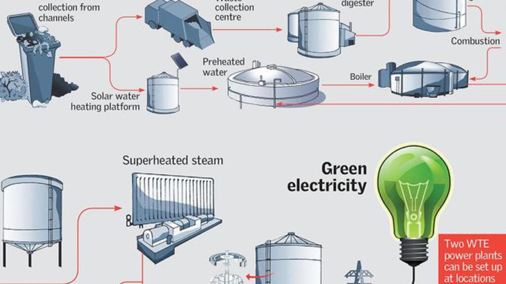
The plastic molding and extrusion industries are critical components of manufacturing, with applications spanning various sectors, including automotive, electronics, packaging, and consumer goods. These industries are highly energy-intensive due to the need to melt and shape plastic materials, which generates substantial waste heat. Instead of allowing this heat to be lost, it can be captured and converted into electricity using various heat recovery technologies. This section explores how waste heat from plastic molding and extrusion processes can be harnessed to generate electricity, thereby improving energy efficiency and sustainability.
a. Waste Heat Generation in Plastic Molding and Extrusion
- Key Processes Generating Heat:
- Extrusion: In extrusion, raw plastic is melted and forced through a mold to create continuous shapes such as pipes, films, and sheets. The process requires heating the plastic to a molten state, and much of the energy used in heating is lost as waste heat. This waste heat is typically released through exhaust gases, cooling water, or heated surfaces.
- Injection Molding: Injection molding involves injecting molten plastic into a mold under high pressure to form various components. Like extrusion, significant heat is generated during the melting and cooling phases of the process. Heat is typically lost from the molds, the plastic melt, and the cooling systems.
- Blow Molding: Blow molding, used to make hollow plastic products like bottles, also generates significant waste heat during the heating and forming stages. Heat is often released through cooling systems and exhaust air, which can be captured for electricity generation.
- Compression Molding: This process, commonly used for thermosetting plastics, involves heating and compressing plastic material in a mold. The heat used to soften and shape the material is often lost to the environment.
- Types of Waste Heat:
- High-Temperature Waste Heat: This waste heat typically originates from the extrusion and injection molding processes where temperatures exceed 200°C. This heat can be recovered and used in systems like Organic Rankine Cycle (ORC) or steam turbines to generate electricity.
- Medium-Temperature Waste Heat: Waste heat in the range of 100°C to 200°C is typically released from cooling systems, exhaust air, and surface temperatures during the molding processes. This heat can be efficiently recovered using ORC systems or heat exchangers.
- Low-Temperature Waste Heat: Lower temperatures (below 100°C) are often produced by ventilation, cooling water, and air handling systems. Though challenging to recover for electricity generation, it can be repurposed for preheating water or other process-related needs.
b. Technologies for Generating Electricity from Waste Heat
- Organic Rankine Cycle (ORC):
- Overview: The Organic Rankine Cycle (ORC) is a technology that recovers waste heat to generate electricity. ORC systems use organic fluids with lower boiling points than water, making them ideal for converting heat from medium- and low-temperature waste streams.
- Application in Plastic Molding and Extrusion: In the plastic molding and extrusion industries, ORC systems can be used to recover waste heat from the extrusion process, cooling systems, and exhaust gases. The recovered heat drives an organic fluid through a turbine or generator, producing electricity.
- Benefits: ORC technology is ideal for the plastic molding and extrusion sectors, where waste heat is commonly generated at temperatures that fall within the range suitable for ORC systems (between 100°C and 300°C). This allows manufacturers to generate electricity from heat that would otherwise be wasted, improving the overall energy efficiency of the plant.
- Steam Rankine Cycle (SRC):
- Overview: The Steam Rankine Cycle (SRC) is a mature and widely used method for converting thermal energy into mechanical energy. It involves using heat to produce steam, which drives a turbine connected to a generator to produce electricity.
- Application in Plastic Molding and Extrusion: For high-temperature waste heat sources, such as those generated during plastic extrusion or injection molding, an SRC system can effectively convert this heat into steam, which is then used to generate electricity.
- Benefits: SRC systems are highly efficient for plants that generate large quantities of high-temperature waste heat. The steam produced can be used to power turbines that generate electricity, providing a reliable and scalable solution for large-scale manufacturing operations.
- Heat Exchangers and Heat Pumps:
- Heat Exchangers: Heat exchangers can capture heat from air or cooling systems and transfer it to water or another fluid, which can then be used to generate electricity through a turbine or to preheat water for use in other processes. In plastic molding and extrusion, heat exchangers can recover waste heat from the cooling stages or exhaust gases.
- Heat Pumps: Heat pumps are devices that transfer heat from a low-temperature source to a high-temperature source. They can be used to capture low- to medium-temperature waste heat from cooling systems or ventilation and convert it into usable electricity or process heat.
- Benefits: Heat exchangers and heat pumps are versatile technologies that can be used in conjunction with ORC or SRC systems to optimize waste heat recovery in plastic molding and extrusion facilities.
- Thermoelectric Generators (TEGs):
- Overview: Thermoelectric generators (TEGs) convert temperature differences directly into electricity using the Seebeck effect. These systems are suitable for capturing small amounts of heat from low- to medium-temperature sources.
- Application in Plastic Molding and Extrusion: TEGs can be installed in plastic molding and extrusion facilities to capture heat from exhaust gases, surface temperatures, or cooling systems. While they produce smaller amounts of electricity compared to ORC or SRC systems, TEGs can be an effective solution for supplementing power needs or operating auxiliary equipment.
- Benefits: TEGs are compact, reliable, and require minimal maintenance, making them ideal for smaller-scale waste heat recovery applications or where space is limited.
c. Economic and Environmental Benefits
- Reduced Energy Costs:
- Capturing and converting waste heat into electricity reduces the need for external power from the grid, resulting in significant savings on energy bills. By using heat recovery systems like ORC or SRC, plastic molding and extrusion companies can offset their high energy consumption and improve their bottom line.
- For facilities that rely heavily on high-temperature processes, recovering waste heat offers a valuable opportunity to generate electricity and reduce dependence on expensive, non-renewable energy sources.
- Improved Sustainability:
- The plastic molding and extrusion industries are energy-intensive and contribute to carbon emissions. By utilizing waste heat recovery systems, manufacturers can reduce their carbon footprint, supporting sustainability goals and meeting environmental regulations.
- Furthermore, waste heat recovery helps decrease overall environmental impacts by reducing emissions, minimizing the release of heat into the atmosphere, and supporting the circular economy by reusing energy that would otherwise be wasted.
- Return on Investment (ROI):
- The financial return on investment for waste heat recovery technologies depends on the scale of the facility, the amount of waste heat generated, and local energy prices. In larger facilities with high energy consumption, the ROI is typically faster, ranging from 2 to 5 years.
- For smaller plastic molding and extrusion operations, the ROI might be longer, but the long-term savings on energy costs and the potential for operational improvements make waste heat recovery systems a worthwhile investment.
- Energy Independence:
- By generating electricity from waste heat, plastic molding and extrusion facilities can reduce their reliance on external electricity providers. This energy independence provides stability in the face of energy price fluctuations and ensures a more consistent power supply.
- In regions where grid reliability is a concern, waste heat recovery systems can provide an additional layer of energy security, reducing the risk of downtime or production interruptions.
d. Challenges and Considerations
- Capital Investment:
- The initial investment for waste heat recovery systems, particularly ORC or SRC systems, can be high. However, the long-term energy savings and potential government incentives for energy-efficient systems can offset these costs over time.
- Smaller-scale systems like thermoelectric generators or heat exchangers may offer a more affordable entry point for smaller operations or facilities with less waste heat to recover.
- Maintenance and Operational Complexity:
- Waste heat recovery systems require regular maintenance to ensure optimal performance. For ORC and SRC systems, this may involve monitoring and servicing the turbine, heat exchangers, and associated components.
- Smaller systems like TEGs or heat pumps typically require less maintenance but still benefit from periodic checks to ensure efficient operation.
- Space Requirements:
- Larger waste heat recovery systems like ORC and SRC typically require significant space for installation. For plants with limited space, careful planning is necessary to integrate these systems without disrupting existing operations.
- Smaller systems like TEGs or heat pumps have a smaller footprint and may be more easily retrofitted into existing plants, making them a more practical solution for space-constrained facilities.
- Compatibility with Existing Processes:
- The suitability of waste heat recovery systems depends on the temperature and consistency of the waste heat generated by plastic molding and extrusion processes. For optimal performance, the waste heat needs to be at the right temperature range for the selected system (e.g., ORC or SRC).
- Custom solutions or hybrid systems may be required to recover heat from different temperature ranges or from multiple heat sources within a plant.
e. Future Trends and Innovations
- Integration with Industry 4.0:
- The future of waste heat recovery in plastic molding and extrusion could involve greater integration with digital technologies. Sensors, real-time monitoring, and data analytics could optimize heat recovery processes, increase efficiency, and predict when maintenance is required to ensure minimal downtime.
- The use of artificial intelligence (AI) and machine learning could further enhance the performance of waste heat recovery systems, continuously adjusting them to adapt to changing production conditions.
- Hybrid Heat Recovery Systems:
- Hybrid systems that combine multiple technologies, such as ORC, SRC, and heat exchangers, could become more common in plastic molding and extrusion plants. These systems would be more versatile and capable of recovering waste heat across a broader temperature range, improving overall energy efficiency.
- Integration with renewable energy sources such as solar or wind could also help enhance the sustainability of plastic manufacturing operations, making them more resilient to energy price fluctuations.
- Advanced Materials and Thermoelectric Devices:
- Advances in thermoelectric materials could make TEGs more efficient and cost-effective for use in plastic molding and extrusion facilities. New materials that can better withstand high temperatures and convert waste heat into electricity more efficiently may increase the adoption of TEGs in the industry.
- The development of more efficient heat exchangers and heat pumps could further enhance the ability to recover low- and medium-temperature waste heat, expanding the range of heat recovery options available to manufacturers.
Conclusion
The plastic molding and extrusion industries generate substantial amounts of waste heat, which can be captured and converted into electricity through technologies such as Organic Rankine Cycle (ORC), Steam Rankine Cycle (SRC), heat exchangers, heat pumps, and thermoelectric generators (TEGs). By implementing these waste heat recovery systems, manufacturers can significantly reduce energy consumption, improve sustainability, and lower operational costs. While the initial investment and space requirements may present challenges, the long-term financial and environmental benefits make waste heat recovery an attractive option for plastic molding and extrusion facilities. As technologies evolve, the potential for even more efficient and cost-effective waste heat recovery solutions will continue to grow, helping the industry become more energy-efficient and environmentally responsible.
37. Generating Electricity using Waste Heat from Glass Manufacturing
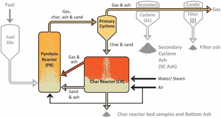
The glass manufacturing industry is a key sector in various markets, including construction, automotive, packaging, and consumer goods. The production of glass involves the melting of raw materials such as sand, soda ash, and limestone in a furnace at temperatures ranging from 1,400°C to 1,600°C. This process generates significant amounts of waste heat, which is typically released into the atmosphere or used inefficiently. By capturing and utilizing this waste heat, glass manufacturers can reduce energy consumption, lower costs, and generate electricity. This section explores the methods and technologies for generating electricity from waste heat in the glass manufacturing process.
a. Waste Heat Generation in Glass Manufacturing
- Furnace Heating and Melting:
- Melting Furnace: The melting furnace, which melts the raw materials to form molten glass, is the most energy-intensive part of the glass manufacturing process. The high temperatures in the furnace cause a large amount of heat to be released as waste heat in the form of exhaust gases, flue gas, and radiated heat from the furnace surfaces.
- Regenerative and Recuperative Furnaces: In regenerative furnaces, heat recovery is achieved by using heat exchangers to store heat from exhaust gases, which can be reused to preheat the incoming combustion air. Recuperative furnaces also capture heat from the exhaust gases, but they have a more direct, one-pass design. These heat recovery systems can reduce overall fuel consumption, but substantial amounts of waste heat are still left unutilized, presenting an opportunity for further energy recovery.
- Cooling Process:
- After the molten glass is formed into desired shapes, it undergoes a cooling process to solidify. Cooling in the form of air cooling, water cooling, or controlled atmosphere cooling can result in substantial amounts of low-temperature waste heat. This waste heat is often released into the atmosphere, contributing to inefficiencies in energy use.
- Heat from Other Operations:
- Other operations in the glass manufacturing process, such as forming, annealing, and coating, can also produce waste heat. While these operations generate lower amounts of heat compared to the melting furnace, the accumulated waste heat from multiple processes can be effectively captured and converted into electricity.
b. Technologies for Generating Electricity from Waste Heat
- Organic Rankine Cycle (ORC):
- Overview: The Organic Rankine Cycle (ORC) is an effective technology for recovering medium-temperature waste heat. It uses an organic fluid with a lower boiling point than water, allowing it to operate at lower temperatures. This makes ORC systems ideal for recovering heat from glass furnaces, cooling processes, and exhaust gases in the 100°C to 300°C range.
- Application in Glass Manufacturing: In glass manufacturing, ORC systems can be installed to capture and utilize waste heat from the melting furnace, exhaust gases, or cooling systems. The captured heat is used to vaporize an organic fluid, which drives a turbine connected to a generator, producing electricity.
- Benefits: ORC systems are well-suited for glass manufacturing plants because they can recover heat from a variety of sources, including lower-temperature waste heat. This allows manufacturers to reduce their reliance on external energy sources and increase their operational efficiency.
- Steam Rankine Cycle (SRC):
- Overview: The Steam Rankine Cycle (SRC) is a more traditional and widely used technology for converting thermal energy into electricity. It involves using high-temperature waste heat to produce steam, which drives a turbine connected to a generator.
- Application in Glass Manufacturing: For glass manufacturing facilities that generate high-temperature waste heat (above 250°C), the Steam Rankine Cycle is an effective method of recovering heat. The heat is used to produce steam, which can power turbines to generate electricity or be used for other operational needs such as heating.
- Benefits: SRC systems are efficient for high-temperature heat recovery, which is ideal for glass manufacturing, where furnaces operate at very high temperatures. The ability to generate electricity directly from the recovered heat can lead to significant energy savings and a reduced carbon footprint.
- Waste Heat Boilers:
- Overview: Waste heat boilers are used to capture high-temperature exhaust gases from furnaces and convert them into steam or hot water. The steam produced can either be used for electricity generation (via a steam turbine) or for process heating.
- Application in Glass Manufacturing: Waste heat boilers can be installed in glass manufacturing plants to recover heat from furnace exhaust gases. The recovered heat is used to generate steam, which can be fed into a steam turbine to generate electricity or used for other processes.
- Benefits: Waste heat boilers are a relatively simple and cost-effective solution for capturing high-temperature waste heat. By converting exhaust gases into usable steam, these systems can significantly improve the overall energy efficiency of the glass manufacturing process.
- Heat Exchangers and Heat Pumps:
- Heat Exchangers: Heat exchangers can be used to recover waste heat from both high- and low-temperature sources. They work by transferring heat from the waste stream to a secondary fluid, which can then be used for electricity generation or preheating purposes.
- Heat Pumps: Heat pumps can capture waste heat from lower-temperature sources, such as cooling systems, and transfer it to a higher temperature for use in generating electricity or preheating materials.
- Benefits: Heat exchangers and heat pumps are versatile technologies that can be employed to recover waste heat across a wide temperature range. When combined with other systems like ORC or SRC, they can enhance the overall efficiency of waste heat recovery in glass manufacturing.
- Thermoelectric Generators (TEGs):
- Overview: Thermoelectric generators (TEGs) use the Seebeck effect to convert temperature differences directly into electricity. While TEGs are typically used for small-scale applications, they can be installed to capture heat from specific components in the glass manufacturing process, such as furnace surfaces or exhaust pipes.
- Application in Glass Manufacturing: TEGs can be installed on various surfaces within a glass manufacturing plant to capture low- to medium-temperature waste heat and convert it into electricity. This can be particularly useful for supplementing power needs or operating small equipment.
- Benefits: TEGs are compact, reliable, and require minimal maintenance, making them ideal for localized waste heat recovery in areas where other technologies may not be feasible.
c. Economic and Environmental Benefits
- Reduced Energy Costs:
- Recovering waste heat to generate electricity can help glass manufacturers reduce their reliance on external power sources, leading to significant savings on energy costs. The implementation of ORC, SRC, or waste heat boilers can offset a substantial portion of a plant’s electricity consumption, improving the facility’s overall energy efficiency.
- Lower Carbon Emissions:
- By recovering and utilizing waste heat, glass manufacturers can reduce the amount of energy they need to purchase from the grid, which is often derived from fossil fuels. This results in lower carbon emissions, contributing to the company’s sustainability efforts and helping meet regulatory requirements for emissions reductions.
- In addition to direct emissions reductions, waste heat recovery systems can help glass manufacturers comply with environmental standards, improving their public image and market competitiveness.
- Return on Investment (ROI):
- The ROI for waste heat recovery systems in glass manufacturing varies depending on the scale of the facility, the amount of waste heat available, and local energy prices. For larger glass plants with significant waste heat generation, the ROI can typically be realized within 2 to 5 years, making these technologies a valuable long-term investment.
- The economic return may be further enhanced through government incentives for energy efficiency improvements, such as tax credits or grants for the installation of waste heat recovery systems.
- Energy Independence:
- By generating electricity from waste heat, glass manufacturers can reduce their dependence on grid-supplied electricity. This provides greater energy security, reduces exposure to fluctuating energy prices, and allows for more stable operations, especially in regions with unreliable electricity supply.
d. Challenges and Considerations
- Initial Capital Investment:
- The upfront costs of waste heat recovery systems, particularly ORC, SRC, and waste heat boilers, can be significant. However, the long-term savings on energy costs can offset these initial investments, making waste heat recovery a cost-effective solution over time.
- Smaller facilities may find it more difficult to justify the investment in large-scale systems, but modular or smaller systems like TEGs can offer a more affordable entry point.
- Maintenance and Operational Complexity:
- Waste heat recovery systems require regular maintenance to ensure they continue to operate efficiently. For systems like ORC and SRC, this may involve servicing turbines, heat exchangers, and associated components. While these systems typically require more maintenance than smaller technologies like TEGs, they offer higher electricity generation potential.
- Proper training and expertise are required to operate and maintain waste heat recovery systems, which could add complexity to existing operations.
- Space Requirements:
- Larger waste heat recovery systems, particularly ORC and SRC, require considerable space for installation. This can be challenging for glass plants with limited available space or where the plant layout does not easily accommodate new equipment.
- Smaller systems like TEGs or heat pumps, which have a smaller footprint, may be more suitable for retrofitting into existing plants without significant disruptions to production processes.
- Compatibility with Existing Processes:
- The efficiency of waste heat recovery systems depends on the temperature and consistency of the waste heat generated. Glass manufacturing processes typically produce high- and low-temperature waste heat, and choosing the right technology for each heat source is crucial for maximizing energy recovery.
- Custom solutions may be needed to capture and utilize waste heat from multiple sources or processes within the plant.
e. Future Trends and Innovations
- Integration with Smart Manufacturing:
- Future advancements in waste heat recovery technologies in the glass industry may include greater integration with smart manufacturing systems. Sensors, real-time data monitoring, and machine learning could help optimize heat recovery, increase efficiency, and predict maintenance needs, thereby reducing downtime and improving overall productivity.
- Digital twins and predictive analytics could also play a role in designing more efficient waste heat recovery systems that adjust to varying production conditions and optimize energy savings.
- Hybrid Heat Recovery Systems:
- Hybrid systems that combine ORC, SRC, heat exchangers, and TEGs could become more common in glass manufacturing plants. These systems would allow for more flexibility in recovering heat from multiple temperature ranges and heat sources, improving the overall energy efficiency of the plant.
- Integrating renewable energy sources, such as solar or wind, with waste heat recovery systems could further enhance sustainability efforts and reduce reliance on grid electricity.
- Advanced Materials for Heat Recovery:
- Advances in materials science, such as the development of high-performance thermoelectric materials and improved heat exchanger designs, could lead to more efficient waste heat recovery systems for glass manufacturing.
- The use of advanced materials that can withstand high temperatures and improve heat transfer efficiency may help lower the cost and increase the effectiveness of waste heat recovery technologies.
Conclusion
The glass manufacturing industry generates large amounts of waste heat, particularly from the melting furnace and cooling processes. By adopting waste heat recovery technologies such as Organic Rankine Cycle (ORC), Steam Rankine Cycle (SRC), waste heat boilers, heat exchangers, and thermoelectric generators (TEGs), manufacturers can significantly reduce energy consumption, generate electricity, and enhance operational efficiency. The economic and environmental benefits of waste heat recovery, including lower energy costs, reduced carbon emissions, and improved sustainability, make these technologies an attractive option for the glass manufacturing sector. As innovations in energy recovery technologies continue to evolve, the potential for even more efficient and cost-effective systems will help glass manufacturers reduce their reliance on external energy sources and contribute to global efforts to reduce industrial energy consumption.
38. Generating Electricity using Waste Heat from Chemical Manufacturing
Chemical manufacturing is a critical sector that produces a wide range of products including pharmaceuticals, fertilizers, plastics, petrochemicals, and specialty chemicals. The processes involved in chemical manufacturing, such as reactions, distillation, and drying, are highly energy-intensive and often generate substantial amounts of waste heat. This waste heat is frequently discarded into the environment, which represents both an energy loss and an opportunity to improve the energy efficiency of the manufacturing process. By recovering and utilizing waste heat, chemical manufacturers can reduce operational costs, enhance energy efficiency, and generate electricity, making these processes more sustainable.
a. Sources of Waste Heat in Chemical Manufacturing
- Exothermic Reactions:
- Many chemical processes involve exothermic reactions, which release heat as a byproduct. These reactions include processes like polymerization, combustion, and oxidation. In most cases, the heat released in these reactions is not fully captured and is lost to the environment. Instead of being discarded, this waste heat could be utilized to generate electricity or provide useful heat to other parts of the plant.
- Furnaces and Heaters:
- Furnaces and heaters are used in chemical plants for various tasks, such as providing the necessary heat for reactions, heating raw materials, or drying products. The exhaust gases from these systems are often at high temperatures (typically above 300°C), making them an ideal source for waste heat recovery. However, much of this heat is typically lost to the atmosphere, making it an untapped resource.
- Distillation Columns:
- Distillation is one of the most common processes used in chemical manufacturing to separate mixtures based on differences in boiling points. The distillation process generates a significant amount of waste heat, primarily from the reboilers at the bottom of the distillation column. This waste heat can be captured and used to generate electricity or be redirected for other uses, such as preheating incoming feedstock or powering auxiliary equipment.
- Cooling Systems:
- Cooling systems, used to cool down products or remove excess heat from chemical reactions, are another major source of waste heat in chemical plants. Cooling towers, heat exchangers, and refrigeration systems often release large amounts of heat into the environment. This heat, especially from low-temperature sources, could be recovered and used for power generation or other processes.
- Drying Processes:
- Drying is a common step in chemical manufacturing, especially for products like polymers, powders, or food ingredients. The drying process typically involves heating and evaporating water or other solvents from the product. The excess heat from these drying processes is often released as waste heat, which can be captured and repurposed.
b. Technologies for Generating Electricity from Waste Heat in Chemical Manufacturing
- Organic Rankine Cycle (ORC):
- Overview: The Organic Rankine Cycle (ORC) is an efficient technology for recovering heat from medium to low-temperature sources, which makes it ideal for chemical plants. ORC systems use organic fluids with low boiling points to generate power from waste heat, making them well-suited for recovering heat from processes that produce waste heat in the 100°C to 300°C range.
- Application in Chemical Manufacturing: ORC can be used to recover waste heat from a variety of chemical manufacturing processes, including exothermic reactions, distillation columns, and cooling systems. The captured heat is used to vaporize an organic fluid, which drives a turbine connected to a generator, thus producing electricity.
- Benefits: ORC systems are flexible and can be tailored to different temperature ranges and heat sources. They offer a relatively low-cost and efficient solution for recovering and converting waste heat into usable electricity in chemical plants.
- Steam Rankine Cycle (SRC):
- Overview: The Steam Rankine Cycle (SRC) is a traditional method of generating electricity from high-temperature waste heat. In SRC, steam is produced from high-temperature waste heat, and the steam is used to drive a turbine connected to a generator.
- Application in Chemical Manufacturing: For chemical plants that generate high-temperature waste heat, such as from furnaces, reboilers, or reactors, the SRC is a highly effective technology. The steam produced can be used to power turbines and generate electricity, reducing the need for external energy sources.
- Benefits: SRC is widely used in industrial applications for high-temperature waste heat recovery, offering reliable and scalable electricity generation from large-scale waste heat sources.
- Heat Recovery Steam Generators (HRSG):
- Overview: Heat Recovery Steam Generators (HRSG) are designed to recover heat from exhaust gases from industrial processes, such as gas turbines or furnaces. The recovered heat is used to produce steam, which can then be used to drive turbines for power generation.
- Application in Chemical Manufacturing: HRSG systems can be used to recover heat from the exhaust gases of chemical reactors, incinerators, or combustion processes in chemical plants. The steam generated can be used to produce electricity, or it can be used for process heating or other needs within the plant.
- Benefits: HRSG systems are highly efficient at recovering heat from high-temperature exhaust gases, making them well-suited for use in large-scale chemical plants. They also provide flexibility in terms of how the recovered heat is utilized, whether for electricity generation or process applications.
- Waste Heat Boilers:
- Overview: Waste heat boilers capture heat from exhaust gases, converting it into steam that can be used for electricity generation or other industrial processes. These boilers are particularly useful in applications where high-temperature waste heat is abundant.
- Application in Chemical Manufacturing: Waste heat boilers can be installed in chemical plants to recover heat from furnace exhaust gases, reaction heat, or other high-temperature sources. The recovered heat is used to generate steam, which can drive a steam turbine to produce electricity or serve as process steam for other operations.
- Benefits: Waste heat boilers are an economical solution for recovering heat from exhaust gases and generating steam. They can be integrated with other systems like ORC or SRC to further optimize energy recovery and improve plant efficiency.
- Thermoelectric Generators (TEGs):
- Overview: Thermoelectric generators (TEGs) use the Seebeck effect to convert temperature differences directly into electrical power. TEGs can be installed on surfaces that are exposed to waste heat, such as the walls of furnaces, heat exchangers, or exhaust pipes.
- Application in Chemical Manufacturing: TEGs can be used to recover low-to-medium temperature waste heat from various processes, including cooling systems, heat exchangers, and reactors. By converting temperature gradients into electricity, TEGs provide a compact and reliable solution for small-scale waste heat recovery in chemical plants.
- Benefits: TEGs are low-maintenance, compact, and can be deployed in localized areas to capture small amounts of waste heat. They are ideal for supplementing power needs in remote or hard-to-reach locations within the chemical plant.
c. Economic and Environmental Benefits
- Cost Reduction:
- Waste heat recovery systems can significantly reduce the operational costs of chemical plants by decreasing the need for external energy sources. Technologies like ORC, SRC, and waste heat boilers provide an opportunity to generate electricity on-site, reducing electricity bills and providing a return on investment over time.
- The use of recovered waste heat for preheating feedstock or other processes can also reduce the overall fuel consumption, leading to lower operating expenses.
- Environmental Benefits:
- The recovery and utilization of waste heat help to reduce greenhouse gas emissions by decreasing the reliance on fossil fuel-based electricity generation. By generating electricity on-site from waste heat, chemical plants can reduce their carbon footprint and contribute to global efforts to mitigate climate change.
- Reducing the environmental impact of energy consumption in chemical plants can also help businesses comply with increasingly stringent environmental regulations and improve their sustainability profiles.
- Energy Security:
- By generating electricity from waste heat, chemical plants can become less reliant on grid electricity, which is subject to price fluctuations and potential disruptions. This energy independence provides greater operational stability and security, particularly in regions with unreliable electricity supplies.
- Return on Investment (ROI):
- The financial returns from waste heat recovery systems can be substantial, especially for large chemical manufacturing plants with significant waste heat generation. The ROI typically depends on the scale of the plant, the amount of recoverable waste heat, and the local cost of energy. Generally, the payback period for these systems ranges from 2 to 5 years, making them an attractive investment for many chemical manufacturers.
d. Challenges and Considerations
- Initial Investment Costs:
- Waste heat recovery technologies, such as ORC, SRC, and waste heat boilers, require significant upfront capital investment. However, the long-term savings on energy costs and the ability to generate electricity on-site can offset the initial investment over time.
- Smaller chemical plants with limited waste heat generation may find it difficult to justify the high capital costs of large-scale systems, but modular systems or hybrid solutions could provide a more affordable solution.
- Maintenance and Operational Complexity:
- Advanced waste heat recovery systems require regular maintenance and monitoring to ensure efficient operation. Systems like ORC and SRC have moving parts, including turbines and pumps, which need to be serviced to maintain optimal performance.
- Plant operators may require specialized training to operate and maintain these systems effectively. Maintenance costs and operational complexity should be factored into the overall cost-benefit analysis.
- Compatibility with Existing Infrastructure:
- Integrating waste heat recovery systems into existing chemical manufacturing processes may require significant modifications to the plant’s infrastructure. For instance, the installation of heat exchangers, turbines, and steam generators may involve reconfiguring existing equipment or adding new components to capture and convert waste heat.
- Retrofitting older plants with waste heat recovery systems can be challenging, particularly if the plant’s design was not originally optimized for energy recovery.
- Heat Source Variability:
- The availability and temperature of waste heat in chemical manufacturing processes can vary over time due to fluctuations in production levels or operational conditions. Waste heat recovery systems must be designed to accommodate this variability to maximize efficiency and minimize downtime.
- In some cases, a combination of technologies may be required to capture and utilize waste heat from different sources with varying temperatures.
e. Future Trends and Innovations
- Advanced Heat Recovery Technologies:
- The future of waste heat recovery in chemical manufacturing is likely to involve innovations in materials, system integration, and efficiency optimization. New high-performance thermoelectric materials and improved heat exchanger designs could significantly increase the efficiency of heat recovery systems.
- Hybrid systems that combine ORC, SRC, and TEGs may become more common, offering a more flexible and cost-effective solution for recovering heat from a variety of waste heat sources.
- Smart Manufacturing Integration:
- As chemical manufacturing plants move toward more intelligent, data-driven operations, the integration of waste heat recovery systems with smart manufacturing platforms will become more common. Real-time monitoring, predictive analytics, and machine learning algorithms could help optimize heat recovery, improving overall efficiency and reducing energy consumption.
- Sustainability and Circular Economy:
- The increasing emphasis on sustainability and the circular economy will drive further investments in waste heat recovery technologies. Companies that adopt waste heat recovery systems not only improve their energy efficiency but also contribute to a more sustainable and circular industrial ecosystem.
- Collaboration between industries and technology providers to develop and implement waste heat recovery systems will help accelerate the transition to greener, more energy-efficient manufacturing processes.
Conclusion
Chemical manufacturing processes generate large amounts of waste heat that can be recovered and utilized to generate electricity or provide other energy needs for the plant. Technologies such as Organic Rankine Cycle (ORC), Steam Rankine Cycle (SRC), waste heat boilers, heat exchangers, and thermoelectric generators (TEGs) provide viable solutions for recovering waste heat and converting it into usable power. By implementing waste heat recovery systems, chemical manufacturers can reduce their energy consumption, lower costs, decrease their carbon footprint, and improve their overall sustainability. As innovation in energy recovery technologies continues, the chemical manufacturing sector will likely see even more efficient and cost-effective solutions to harness the potential of waste heat for electricity generation and process optimization.
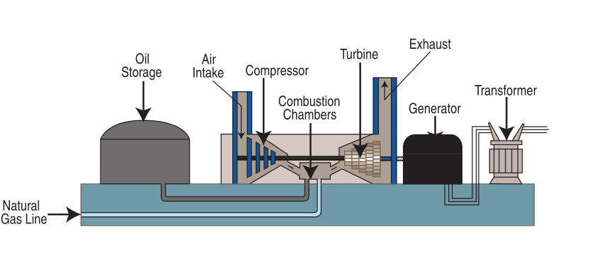
Generating electricity from heat produced in power station boilers is a fundamental process in the energy generation industry. Power stations, whether coal, gas, or nuclear-fired, rely on large-scale boilers to produce steam, which drives turbines connected to electricity generators. These boilers burn fuel to generate high-temperature steam, which is then used to power the turbines that produce electricity. The process involves several steps, from fuel combustion to heat generation, steam production, and the conversion of thermal energy into mechanical energy. The use of waste heat from these boilers for electricity generation is an effective way to enhance the overall efficiency of power plants.
Power station boilers operate under extreme conditions, producing heat that is usually vented as waste energy. However, by capturing and using this waste heat, power plants can recover a portion of this lost energy, improving plant efficiency and reducing fuel consumption. This is especially significant in power stations where efficiency improvements can result in substantial savings and a reduction in the environmental footprint.
The primary method of converting heat from power station boilers into electricity is through a Rankine Cycle, a process that involves using steam to drive a turbine connected to an electrical generator. In a typical thermal power plant, the steam is produced in a boiler by burning fossil fuels or through nuclear reactions. The steam then passes through a turbine, where it expands and drives the blades, which in turn rotate the generator and produce electricity.
The efficiency of power plants is largely determined by how well they can capture and utilize the heat generated in the boiler. In modern power stations, heat recovery systems such as economizers, superheaters, and reheaters are employed to maximize the amount of energy extracted from the burning of fuel. These systems recover heat from exhaust gases and use it to preheat water or generate additional steam, which is then fed into the turbine for power generation.
Waste heat recovery can be particularly beneficial for plants that operate at high temperatures and pressures. Technologies like the Organic Rankine Cycle (ORC) or the Steam Rankine Cycle (SRC) can be adapted to capture lower-temperature waste heat and convert it into usable electricity. These systems are capable of generating power from exhaust gases, cooling water, and other residual heat sources, thus improving the plant’s overall energy efficiency.
Additionally, heat recovery steam generators (HRSGs) can capture the waste heat from gas turbines or other combustion processes and use it to produce steam, which can then be directed to steam turbines for power generation. This integrated approach of capturing heat at multiple stages of the power generation process ensures that more of the energy produced in the boiler is converted into usable electricity, reducing fuel consumption and emissions.
As the global energy landscape moves towards more sustainable practices, the focus is shifting towards improving the efficiency of power plants and reducing carbon emissions. Waste heat recovery technologies play an essential role in this effort, offering a way for power stations to produce more electricity with less fuel. They also support efforts to reduce greenhouse gas emissions by minimizing the amount of waste heat released into the environment.
In the future, advancements in materials science, turbine design, and heat recovery technology could further increase the efficiency of power stations, making them more sustainable and cost-effective. As the demand for cleaner energy increases, the ability to efficiently capture and utilize waste heat will be critical in making power generation more environmentally friendly and economically viable.
The continued development of waste heat recovery systems in power stations is pivotal in addressing the growing concerns about energy efficiency and environmental sustainability. One significant area of focus is improving the efficiency of Rankine Cycle-based systems, such as the Steam Rankine Cycle (SRC) and Organic Rankine Cycle (ORC), in power station boilers. By incorporating advanced materials and designs, these systems can be optimized to handle higher temperature gradients and pressures, leading to greater energy recovery.
For instance, modern heat exchangers with enhanced heat transfer properties can be used to capture more heat from the exhaust gases and increase the overall thermal efficiency of the power station. Advances in thermodynamic cycles, such as regenerative Rankine cycles and combined cycle systems, allow for the use of multiple heat recovery stages, each designed to capture energy at different temperature levels. This multi-stage approach significantly reduces the amount of energy wasted, thus boosting the plant’s net power output while reducing operational costs.
Another promising development is the integration of combined heat and power (CHP) systems, which not only generate electricity from waste heat but also provide heating for nearby industrial processes or district heating systems. In these systems, the waste heat recovered from the boiler is used to produce both electricity and thermal energy, maximizing the efficiency of the plant by utilizing the thermal energy in multiple ways. This integration is particularly beneficial in industrial settings where both electricity and heat are required, reducing reliance on external energy sources and further improving cost-effectiveness.
The adoption of low-emission technologies is another factor driving innovation in waste heat recovery. Many power stations are now incorporating carbon capture and storage (CCS) systems that work alongside heat recovery to minimize the environmental impact. These systems capture CO2 emissions from the exhaust gases before they are released into the atmosphere, significantly reducing the carbon footprint of power generation. When combined with efficient heat recovery methods, these technologies help ensure that power stations remain both environmentally responsible and economically viable in a rapidly changing energy market.
In addition to technological advancements, there is an increasing push for regulatory frameworks and financial incentives that encourage power plants to adopt waste heat recovery systems. Governments and international organizations are recognizing the importance of improving energy efficiency across industries, and as a result, they are implementing policies that incentivize the installation of waste heat recovery technologies. These policies can take the form of tax credits, grants, or subsidies for companies investing in energy-saving systems, which makes it easier for power stations to integrate waste heat recovery solutions without significant financial burden.
As power stations around the world transition to cleaner, more efficient energy production methods, waste heat recovery will play a crucial role in enabling these shifts. By capturing and reusing the heat that is typically lost in the production process, power plants can produce more energy while reducing their environmental impact. As innovation in materials, system designs, and regulatory frameworks continues to evolve, the potential for waste heat recovery to drive sustainability and efficiency in the power generation sector remains strong.
As waste heat recovery technology becomes more advanced, the future of power stations will likely see increased integration of these systems in both new builds and retrofits of older plants. For older power stations, upgrading existing boilers and incorporating waste heat recovery systems could result in significant improvements in overall efficiency. Retrofitting is a cost-effective way to enhance performance without the need for a complete overhaul, allowing for the maximization of the energy potential within the existing infrastructure.
Furthermore, the rise of digitalization and smart monitoring systems in the power generation sector is expected to significantly enhance the operation of waste heat recovery systems. With the advent of Internet of Things (IoT) devices, sensors, and machine learning algorithms, power plants will be able to monitor and optimize their heat recovery systems in real-time. Predictive maintenance, automated control systems, and data-driven decision-making will ensure that waste heat recovery units operate at peak efficiency, minimizing downtime and ensuring a continuous supply of electricity.
As the global focus intensifies on reducing greenhouse gas emissions and combating climate change, the role of waste heat recovery will be critical in achieving ambitious sustainability targets. Beyond reducing the carbon footprint of individual power stations, widespread adoption of waste heat recovery can contribute to broader decarbonization efforts in the energy sector. Power plants equipped with advanced waste heat recovery technologies will be better positioned to meet future emission regulations, as they can produce more energy with fewer emissions.
In addition to its environmental benefits, waste heat recovery is also becoming more economically attractive due to the falling costs of energy-efficient technologies. The prices of materials like thermoelectric generators (TEGs) and advanced heat exchangers are steadily decreasing, making them more accessible to power stations of various sizes. As the technology becomes more cost-competitive, it’s expected that waste heat recovery will no longer be a luxury reserved for the largest power plants, but a standard practice in a wide range of energy facilities.
Global energy transition trends also point to an increasing role for decentralized energy generation, where smaller power plants equipped with waste heat recovery technologies are interconnected to form a more resilient and flexible energy grid. In this scenario, power plants can produce electricity from both renewable sources and waste heat, supporting grid stability by providing a steady and sustainable energy supply.
Finally, as the energy sector increasingly moves towards renewable energy sources, waste heat recovery technologies will play an integral role in hybrid systems. For example, in combined solar and heat recovery systems, solar thermal collectors could work alongside waste heat recovery units to generate electricity more efficiently. This synergy could help power plants transition toward a more diversified energy mix, leveraging both renewable and waste heat energy sources for cleaner, more efficient electricity generation.
The future of generating electricity from waste heat in power stations holds great promise as innovations in technology, materials, and system integration continue to evolve. By enhancing energy efficiency, reducing emissions, and driving cost savings, waste heat recovery will be an essential tool in the transition towards a more sustainable and low-carbon energy future. With a continued focus on improving these systems, the global energy industry will be better equipped to meet the growing demands for cleaner, more reliable, and affordable electricity.
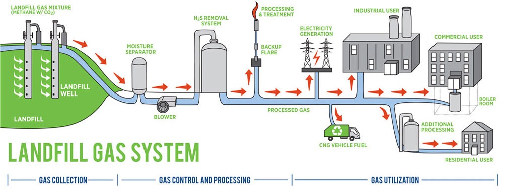
Generating electricity from heat produced in oil refining and cracking processes is an effective way to enhance the energy efficiency of refineries, which are often large consumers of energy. The oil refining industry produces significant amounts of heat, especially during thermal cracking and distillation processes. These processes involve high temperatures to break down crude oil into its various components such as gasoline, diesel, and other valuable by-products. However, a substantial amount of this heat is often released as waste into the environment. By capturing and reusing this waste heat, refineries can generate electricity, reduce energy consumption, and lower their carbon emissions.
The heat generated in oil refining processes can be harnessed using a range of waste heat recovery technologies. One of the most common methods is through the use of a Rankine Cycle or Organic Rankine Cycle (ORC), where waste heat is used to produce steam or vapor. This steam can then be used to drive a turbine, which is connected to an electricity generator. The Rankine Cycle is widely used in industrial applications for waste heat recovery because of its ability to generate electricity from heat at relatively low to moderate temperatures, which is typically the range found in many refining processes.
For oil refineries, the heat recovery system is typically integrated with existing operations. For instance, the hot exhaust gases from the cracking units or distillation columns can be routed through heat exchangers, which transfer the thermal energy to a working fluid. In the case of the Organic Rankine Cycle, the working fluid is often a refrigerant or organic fluid with a lower boiling point than water, enabling efficient heat conversion at lower temperatures. The heated fluid is then vaporized and passed through a turbine, generating mechanical power that is converted into electricity by the generator.
Refining processes such as catalytic cracking, hydrocracking, and distillation often operate at high temperatures and pressures, producing large volumes of waste heat. In many cases, the temperature of the waste heat can range from 200 to 600°C (392 to 1112°F), making it suitable for efficient electricity generation when captured by advanced heat recovery systems. For instance, using combined cycle systems, the waste heat from oil refining can be combined with other energy recovery methods, such as natural gas turbines, to further enhance overall power output.
One significant advantage of using waste heat from oil refining processes is that it reduces the reliance on external electricity sources, decreasing the operational costs of refineries. Instead of purchasing electricity from the grid, refineries can produce a portion of their own power from the heat they are already generating, improving their energy self-sufficiency. This also helps in reducing the overall carbon footprint of the refinery, as the waste heat recovery system allows the plant to operate more efficiently without increasing its reliance on fossil fuels.
Furthermore, incorporating waste heat recovery systems can improve the overall sustainability of the oil refining process. By reducing energy consumption and minimizing waste heat, refineries contribute to lowering their environmental impact. With global initiatives pushing for more sustainable industrial practices, oil refineries are increasingly under pressure to adopt technologies that improve their environmental footprint. Waste heat recovery is one of the most cost-effective and accessible methods for achieving this goal.
Advanced waste heat recovery technologies can also help refineries comply with stringent environmental regulations. Many countries and regions have set regulations aimed at reducing industrial emissions, including those associated with heat waste. By implementing efficient waste heat recovery systems, refineries can not only generate electricity but also comply with these regulations by reducing their overall emissions. Technologies like carbon capture and storage (CCS) can also be combined with waste heat recovery systems to further reduce greenhouse gas emissions, making refineries more environmentally friendly and compliant with global sustainability standards.
In addition to electricity generation, the recovered heat can also be utilized for other refinery processes, such as preheating feedstock for distillation, reducing the need for external heating sources. This can result in significant cost savings and a more efficient overall operation. For example, the integration of combined heat and power (CHP) systems allows the refinery to produce both electricity and thermal energy for industrial processes, maximizing the use of the heat generated and further improving energy efficiency.
As the oil refining industry moves toward more sustainable practices, technologies such as waste heat recovery will become increasingly important. These systems allow refineries to utilize energy that would otherwise be lost, making the entire refining process more energy-efficient and environmentally responsible. With ongoing advancements in heat recovery systems and greater adoption of renewable energy technologies, oil refineries can play a significant role in reducing global energy consumption and emissions while continuing to meet the world’s demand for petroleum products.
As regulatory pressures grow and the push for greener energy practices increases, refineries that incorporate waste heat recovery systems will be better positioned to thrive in a competitive, sustainability-driven market. The ability to generate electricity from the heat produced during oil refining and cracking not only supports energy savings but also helps the industry move toward a more sustainable future.
As the global energy landscape shifts toward cleaner and more sustainable practices, oil refineries that adopt waste heat recovery systems will not only improve their energy efficiency but also enhance their competitiveness in a rapidly evolving market. These systems are particularly valuable in light of increasing energy costs and tightening environmental regulations. By capturing and utilizing waste heat, refineries can reduce their overall energy demand, resulting in lower operating costs and improved margins.
In addition to the environmental benefits, waste heat recovery also contributes to energy security by decreasing a refinery’s reliance on external energy sources. In many regions, refineries are located in areas where energy supply is less stable or where grid electricity can be expensive. By generating a portion of their own electricity, refineries can insulate themselves from fluctuating energy prices and potential power shortages. This improved energy self-sufficiency can provide a competitive advantage, particularly in markets where energy reliability and cost are critical factors in business operations.
Furthermore, there are significant long-term economic benefits to incorporating waste heat recovery systems in refineries. Though the initial capital investment for these technologies can be considerable, the potential for long-term cost savings and increased energy efficiency makes the investment worthwhile. With advancements in technology, the payback period for waste heat recovery systems has been shortened, and the systems are becoming more cost-effective. This trend is expected to continue, as innovation in heat exchangers, turbine efficiency, and working fluids enhances the overall performance of waste heat recovery systems, making them accessible to a wider range of refineries, including smaller or older facilities that may have previously been unable to afford such upgrades.
Moreover, integrating waste heat recovery systems with other technologies, such as combined heat and power (CHP) or cogeneration, is an effective way to optimize refinery operations. In CHP systems, both electricity and useful heat are generated from a single energy source, which increases the overall energy efficiency of the plant. This dual-purpose generation reduces the need for additional fuel sources, further lowering operating costs and minimizing environmental impact.
The adoption of advanced digital technologies is also improving the performance of waste heat recovery systems in oil refineries. IoT sensors, predictive maintenance tools, and real-time monitoring platforms are enabling refineries to better manage and optimize the performance of their heat recovery units. These technologies allow for continuous monitoring of temperature, pressure, and energy flow, which can lead to more precise adjustments and improvements in system efficiency. Additionally, machine learning algorithms can analyze operational data and suggest optimizations, helping refineries achieve higher energy recovery rates and prevent system failures before they occur.
The integration of waste heat recovery with other industrial processes can also open new opportunities for refinery by-products. The recovered heat could be used in other onsite processes, such as chemical production or drying operations, further improving overall efficiency. In some cases, heat that would otherwise go to waste can be transferred to nearby industries or facilities in the form of district heating or shared energy systems. This integration of waste heat between different industries contributes to a more circular and sustainable industrial ecosystem, where waste from one process becomes a valuable input for another.
As sustainability continues to be a central theme in the energy industry, refineries are increasingly turning to innovative technologies such as waste heat recovery to meet both their financial and environmental objectives. The ability to generate electricity from the heat produced during refining and cracking processes not only improves a refinery’s energy efficiency but also helps it comply with stricter environmental regulations, reducing its carbon footprint and overall environmental impact.
Moving forward, it is clear that waste heat recovery will play an important role in making oil refining processes more energy-efficient, cost-effective, and sustainable. By harnessing the energy that would otherwise be wasted, refineries can reduce their dependence on fossil fuels, lower emissions, and contribute to a more sustainable global energy mix. As the technology matures, it is likely that waste heat recovery will become a standard practice in the industry, helping refineries improve their long-term profitability while simultaneously contributing to global efforts to combat climate change.
As oil refineries continue to adopt waste heat recovery systems, there are several key challenges and considerations that need to be addressed to maximize their effectiveness. One of the primary challenges is ensuring that the captured waste heat is of a temperature and quality suitable for conversion into electricity. While some refining processes generate high-temperature waste heat (e.g., from cracking units), other processes may produce lower-temperature waste streams that require more specialized recovery methods. Technologies such as the Organic Rankine Cycle (ORC) are designed to address this challenge by using organic fluids with lower boiling points than water, making it possible to recover energy from lower-temperature heat sources effectively.
Another challenge is the integration of waste heat recovery systems with existing infrastructure. In many cases, refineries are already operating with complex systems, and retrofitting them with heat recovery units may require careful planning to ensure compatibility with current operations. Retrofitting older plants can be particularly challenging, as it may require substantial investments in both time and money to redesign the heat recovery system without disrupting refinery operations. However, with advances in modular designs and prefabricated components, the installation of waste heat recovery systems can be made more straightforward, reducing the complexities of retrofitting.
Economic factors also play a significant role in determining the feasibility of implementing waste heat recovery in refineries. While the operational savings from reduced energy consumption and lower fuel costs can be substantial over the long term, the initial capital investment for setting up the required infrastructure can be high. However, as the technology matures and economies of scale come into play, the cost of implementing waste heat recovery systems is expected to decrease. Financial incentives, such as government subsidies, tax breaks, or grants for clean energy projects, may also help offset the initial investment, making these systems more accessible to refineries of all sizes.
Additionally, the long-term sustainability of waste heat recovery systems depends on the availability of a stable and high-quality heat source. Oil refining processes are subject to fluctuations in feedstock quality, operational conditions, and market dynamics. This variability can affect the consistency of waste heat generation, which in turn impacts the reliability of the energy recovery process. Refineries must carefully monitor these factors and adapt their waste heat recovery systems to account for changing conditions in the refining process, ensuring that they can consistently capture and convert heat into usable electricity.
From an environmental standpoint, it is essential for oil refineries to ensure that waste heat recovery does not simply shift the environmental burden from one part of the operation to another. For example, the installation of heat recovery systems requires careful management of resource use, including water for cooling and energy for system operation. Therefore, optimizing waste heat recovery must be part of a broader energy management strategy that includes minimizing the overall environmental impact of the refinery.
Furthermore, advances in digital technologies, such as data analytics and AI, are increasingly being used to enhance the operation of waste heat recovery systems. Machine learning algorithms can predict energy demand patterns and optimize system operations, ensuring that the refinery maximizes the amount of energy it recovers without overloading or underutilizing the system. Predictive maintenance, enabled by digital sensors and monitoring systems, can also help reduce downtime and prevent equipment failures, improving the overall efficiency of the heat recovery process.
One of the most exciting prospects in the oil refining sector is the potential for collaboration between different industries. For example, refineries that adopt waste heat recovery systems could collaborate with nearby industrial facilities or power plants to exchange heat. This could create a decentralized energy network where waste heat from refineries is shared with other industries, such as chemical manufacturing, district heating systems, or even residential communities. Such initiatives would help create a more efficient, circular energy economy where waste heat is no longer discarded but used to benefit a wide range of stakeholders.
As the global energy transition accelerates, the role of waste heat recovery in oil refineries will only become more critical. Refineries that incorporate advanced heat recovery technologies will be better positioned to meet increasing demands for cleaner, more efficient energy production. The adoption of these technologies will allow refineries to reduce their energy consumption, minimize their carbon footprint, and contribute to global efforts to mitigate climate change.
Looking ahead, it is clear that waste heat recovery will not just be an option for oil refineries—it will become a key component of their energy strategy. By embracing these technologies, refineries can improve their operational efficiency, lower costs, and play a more active role in the transition to a sustainable energy future. With the right combination of technological innovation, financial incentives, and industry collaboration, oil refining can evolve into a more energy-efficient, environmentally responsible sector capable of generating electricity from waste heat while meeting the growing global demand for petroleum products.
Generating electricity from waste heat in glass melting furnaces offers an innovative and efficient way to improve energy consumption in the glass manufacturing industry. Glass production is an energy-intensive process, and a significant amount of heat is often lost through the exhaust gases and molten glass. By capturing and utilizing this waste heat, manufacturers can reduce energy costs, improve efficiency, and contribute to sustainability efforts.
Glass melting furnaces typically operate at very high temperatures, often exceeding 1,200°C (2,192°F), which means that there is considerable heat available for recovery. The key to harnessing this waste heat lies in effectively capturing it through heat exchangers and transferring it to a medium that can drive a power generation system.
One of the most common methods for generating electricity from waste heat in glass melting furnaces is the use of the Rankine Cycle or Organic Rankine Cycle (ORC) systems. In the Rankine Cycle, waste heat is used to produce steam, which drives a steam turbine connected to an electrical generator. However, this system requires the waste heat to be at a sufficiently high temperature to convert the working fluid into steam efficiently.
For lower temperature waste heat, the Organic Rankine Cycle (ORC) can be used instead. ORC systems utilize organic fluids with lower boiling points compared to water, making them more suitable for lower temperature heat recovery (typically between 150°C and 400°C, or 302°F to 752°F). These systems are ideal for glass production processes, where waste heat is often produced at lower temperatures than those required for traditional steam Rankine systems.
Heat recovery steam generators (HRSGs) are another solution used in glass furnaces to capture waste heat. These units are typically installed in the exhaust ducting of the furnace and are designed to recover heat from the flue gases. The HRSG uses this heat to generate steam, which can be used either for mechanical power generation via a steam turbine or for auxiliary purposes such as preheating combustion air for the furnace or heating water used in other parts of the glass manufacturing process.
The integration of waste heat recovery systems in glass furnaces not only helps in generating electricity but also enhances the overall efficiency of the furnace itself. By recovering heat and redirecting it back into the process, manufacturers can reduce the amount of fuel needed for the furnace, thereby lowering energy costs. The additional benefit of reducing the need for external electricity also contributes to cost savings and helps improve the profitability of the glass manufacturing process.
For example, the recovered heat can be used to preheat the combustion air for the furnace. This reduces the energy required to maintain the high temperatures necessary for melting glass, as the combustion air is already at an elevated temperature when introduced into the furnace. This leads to lower fuel consumption and increased energy efficiency, making the entire production process more sustainable.
Another advantage of utilizing waste heat recovery in glass melting furnaces is the potential reduction in emissions. By recovering and reusing the heat that would otherwise be released into the atmosphere, manufacturers can reduce their overall carbon footprint. In addition, the use of waste heat can help companies comply with environmental regulations aimed at reducing emissions from industrial processes.
The economic benefits of implementing waste heat recovery systems in glass furnaces are significant. While the upfront capital investment can be substantial, the long-term savings from reduced fuel consumption and electricity costs often result in a relatively short payback period. As technology advances, the costs of waste heat recovery systems are expected to decrease, making them more accessible to glass manufacturers of all sizes.
The implementation of digital technologies can further enhance the performance of waste heat recovery systems in glass manufacturing. Advanced sensors, real-time monitoring, and data analytics can help operators optimize the operation of heat recovery systems, identify inefficiencies, and perform predictive maintenance to prevent system failures. By monitoring temperature, pressure, and energy usage in real time, operators can make adjustments to improve system performance and ensure that the maximum amount of waste heat is captured and utilized.
Furthermore, combining waste heat recovery with other sustainability initiatives in glass manufacturing can create a more circular approach to energy use. For instance, glass manufacturers can explore opportunities for integrating waste heat recovery with other nearby industries that also generate waste heat. Sharing heat between industries in a local network can reduce the need for additional energy sources and create a more efficient energy ecosystem.
In some cases, the waste heat recovery system can also be coupled with combined heat and power (CHP) technologies, which generate both electricity and useful thermal energy. This system allows the recovered waste heat to be used for heating other parts of the glass manufacturing process, such as the melting furnace, or for district heating applications if the facility is located near a community. By providing both electricity and thermal energy from a single heat source, CHP systems maximize the overall efficiency of the process and provide further economic benefits.
As sustainability continues to be a central focus in industrial sectors, glass manufacturers are increasingly recognizing the value of integrating waste heat recovery technologies into their operations. By reducing energy consumption, lowering fuel costs, and cutting down on emissions, these technologies contribute to the overall sustainability of the glass industry. With rising energy prices and more stringent environmental regulations, waste heat recovery is quickly becoming an essential practice in modern glass manufacturing.
In the future, as technology continues to improve and costs decrease, it is likely that more glass manufacturers will adopt waste heat recovery systems to meet both their economic and environmental goals. By generating electricity from waste heat, glass furnaces can reduce their dependency on external energy sources, lower production costs, and contribute to a more sustainable and energy-efficient manufacturing process.
The continued adoption of waste heat recovery systems in glass melting furnaces also presents opportunities for innovation in terms of system design and integration. One potential development is the refinement of hybrid systems that combine multiple waste heat recovery technologies. For example, a combined system that utilizes both the Rankine Cycle and the Organic Rankine Cycle could be employed to recover waste heat from multiple sources within the glass manufacturing process, each with different temperature profiles. This hybrid approach would allow for more comprehensive and efficient heat recovery, ensuring that the maximum amount of energy is captured from both high- and low-temperature waste streams.
In addition, the use of advanced materials and technologies could improve the efficiency and durability of waste heat recovery systems in glass furnaces. For instance, heat exchangers made from high-performance materials that can withstand the extreme temperatures inside the furnace could increase the heat transfer efficiency and extend the lifespan of the equipment. Nanotechnology and new materials with enhanced thermal conductivity could also play a role in further improving the performance of heat exchangers and heat recovery systems. These advancements could lead to systems that are more compact, more efficient, and easier to maintain.
Another area of potential growth is the integration of waste heat recovery systems with energy storage technologies. In many cases, waste heat recovery systems generate electricity during periods of high production, when the demand for energy is already being met. By coupling the waste heat recovery system with an energy storage solution, such as batteries or thermal storage, manufacturers can store the generated electricity and use it during times of lower production or peak energy demand. This would not only improve the energy self-sufficiency of the glass manufacturing process but also help balance energy consumption, reducing the facility’s reliance on grid electricity.
The global push for greater sustainability and reduced environmental impact is also driving the development of waste heat recovery technologies for glass manufacturing. Many regions are introducing stricter emissions regulations, requiring industries to cut their carbon emissions and increase energy efficiency. By implementing waste heat recovery systems, glass manufacturers can not only meet these regulations but also position themselves as leaders in sustainability. In fact, companies that prioritize energy efficiency and sustainability are likely to attract more investment and appeal to environmentally-conscious consumers and stakeholders, boosting their reputation in the market.
In terms of long-term industry trends, the glass manufacturing sector is expected to continue evolving toward more sustainable practices, with waste heat recovery playing a significant role in this transition. As technology improves and costs decrease, the financial viability of these systems will increase, making them an increasingly attractive option for glass manufacturers worldwide. The growing demand for energy-efficient and low-carbon solutions is pushing companies to explore innovative ways to generate and manage energy, and waste heat recovery is one of the most effective ways to achieve these goals.
Furthermore, as the concept of circular economies becomes more prevalent, glass manufacturers can look for opportunities to collaborate with other industries to share energy and resources. For example, waste heat from glass production could be used to assist in the operations of nearby facilities, such as those in the chemical, food, or paper industries, creating a collaborative and energy-efficient industrial ecosystem. These types of partnerships would allow for greater energy sharing and reduction of waste, contributing to a more sustainable overall industrial landscape.
Overall, the integration of waste heat recovery in glass melting furnaces is a promising path for improving energy efficiency and sustainability in the glass manufacturing industry. By generating electricity from the waste heat that would otherwise be lost, glass manufacturers can reduce their energy consumption, lower operational costs, and cut down on carbon emissions. The continued development of waste heat recovery technologies, along with increased awareness and adoption across the industry, will help refineries play a key role in driving the global transition to a more sustainable energy future.
As more glass manufacturers embrace waste heat recovery, it will become an increasingly essential tool in the industry’s journey toward greater sustainability, helping to reduce environmental impact while improving energy efficiency and profitability. The ongoing advancements in technology, coupled with the growing importance of energy independence and environmental responsibility, make waste heat recovery a key component of the future of glass manufacturing.
As the adoption of waste heat recovery systems continues to grow in the glass manufacturing sector, there are several additional factors that can drive further progress and optimization. For instance, the role of government policies and incentives cannot be understated. Many governments around the world are introducing regulations and offering financial incentives to promote energy efficiency and reduce carbon emissions in industrial sectors. Tax credits, grants, and subsidies for the implementation of waste heat recovery systems can significantly offset the initial capital investment, making these technologies more accessible to glass manufacturers, particularly smaller businesses that may have been hesitant to invest in such systems otherwise.
The regulatory environment is also evolving to include stricter emissions standards and energy consumption limits for industrial facilities. This is creating an urgent need for glass manufacturers to adopt innovative technologies like waste heat recovery, which can help them meet these environmental targets while maintaining competitive production costs. As the pressure to reduce carbon footprints increases, waste heat recovery will become a critical tool in achieving compliance and advancing the sustainability agenda.
Collaboration between industry stakeholders is another factor that could significantly enhance the adoption and effectiveness of waste heat recovery technologies. Glass manufacturers, equipment suppliers, and technology developers can work together to design and implement more customized, efficient, and cost-effective heat recovery systems. These collaborations could lead to the development of new solutions that address the unique challenges faced by the glass industry, such as optimizing heat recovery from the high-temperature zones of melting furnaces or ensuring the durability of heat exchangers in extreme operating conditions.
Technological innovation will also continue to play a crucial role in driving the adoption of waste heat recovery in glass melting furnaces. With ongoing advancements in materials science, thermodynamics, and engineering, new heat recovery systems with higher efficiency and lower operating costs are likely to emerge. For example, research into advanced thermoelectric materials could lead to systems that directly convert waste heat into electricity without the need for mechanical systems like turbines or steam engines. Such innovations could simplify the recovery process and reduce the complexity of installation and maintenance, further encouraging widespread adoption.
Digitalization and automation also have the potential to improve the operation of waste heat recovery systems in glass furnaces. Advanced sensor technology, real-time data monitoring, and predictive analytics can help operators optimize the performance of heat recovery systems by providing detailed insights into system performance, potential inefficiencies, and maintenance needs. Predictive maintenance, powered by machine learning algorithms, can anticipate failures before they occur, ensuring the continuous operation of the system and minimizing downtime. The integration of digital systems into waste heat recovery units would also help maximize energy savings by dynamically adjusting the system’s operations based on real-time data inputs.
In addition to improving internal operations, digital platforms can allow for more precise tracking of energy generation and consumption. This can help glass manufacturers report their energy efficiency improvements and track their progress toward meeting sustainability goals. For example, some companies may choose to use waste heat recovery data to demonstrate their compliance with corporate social responsibility (CSR) objectives or to earn certifications for sustainable practices. This data can also be valuable in terms of securing investment from sustainability-focused financial institutions, as many investors are now prioritizing companies with strong environmental credentials.
The global demand for more sustainable building materials also presents an opportunity for glass manufacturers to use waste heat recovery as a competitive differentiator. Glass is an essential component in a wide range of applications, from architecture and automotive manufacturing to solar energy systems. As demand for environmentally responsible products grows, manufacturers who can demonstrate energy efficiency and low-carbon production methods will likely find themselves at an advantage in the marketplace. Waste heat recovery can be an important element in achieving these sustainability targets and appealing to environmentally-conscious consumers and architects.
Finally, as the technology becomes more mainstream, it is expected that economies of scale will drive further cost reductions. Larger-scale glass manufacturers, in particular, will benefit from the ability to deploy more sophisticated waste heat recovery systems, reaping the financial rewards of increased energy efficiency and reduced reliance on external power sources. As the technology matures, smaller glass producers will also have access to more affordable and accessible solutions, ensuring that waste heat recovery becomes a standard practice across the industry.
In conclusion, the future of generating electricity from waste heat in glass melting furnaces looks promising, driven by a combination of technological advancements, regulatory pressure, economic incentives, and industry collaboration. By leveraging the potential of waste heat recovery systems, glass manufacturers can significantly improve their energy efficiency, lower operational costs, reduce emissions, and enhance their sustainability profile. As these systems become more cost-effective, reliable, and scalable, waste heat recovery is poised to play an increasingly vital role in the glass manufacturing sector, helping the industry meet the challenges of a rapidly changing energy landscape and contribute to a more sustainable future.
Generating Electricity using Heat from Carbon Black Production

Generating electricity from waste heat in the carbon black production process presents an opportunity to enhance energy efficiency, reduce operational costs, and contribute to sustainability. Carbon black is a key material used in a variety of industries, including rubber production, automotive parts, coatings, plastics, and even electronics. The process of producing carbon black is energy-intensive, involving high-temperature reactors to decompose hydrocarbons in the absence of oxygen. The heat generated during this process is often released into the atmosphere as waste, but it can be captured and converted into usable energy through advanced waste heat recovery systems.
The production of carbon black typically involves processes like the furnace black process or the thermal black process. Both methods generate significant amounts of high-temperature exhaust gases, which can be harnessed for electricity generation. A well-designed waste heat recovery system captures this heat from the exhaust gases and transfers it to a working fluid, which then drives a turbine or generator to produce electricity.
One of the most effective technologies for converting waste heat into electricity in carbon black production is the Organic Rankine Cycle (ORC). The ORC uses an organic fluid with a lower boiling point than water, which is more suitable for recovering heat from lower to medium-temperature sources, such as the exhaust gases from carbon black production. This makes the ORC particularly well-suited for capturing heat in the range of 150°C to 400°C (302°F to 752°F), which is common in the carbon black production process.
In this system, the heat captured from the exhaust gases is used to vaporize the organic fluid, which then expands and drives a turbine connected to a generator. The generator produces electricity, which can either be used to power the carbon black production process itself or be sold back to the grid, offering a potential revenue stream. After the fluid passes through the turbine, it is condensed back into a liquid form, and the cycle is repeated.
Another promising technology for generating electricity from waste heat in carbon black production is the use of heat recovery steam generators (HRSGs). These systems capture the high-temperature exhaust gases from the carbon black reactors and use them to generate steam. This steam can then be used to drive a steam turbine and produce electricity. While HRSG systems are typically more suited for higher-temperature waste heat sources, they can be adapted to the temperature profile of carbon black production by optimizing the heat recovery section of the system.
The benefits of implementing waste heat recovery systems in carbon black production are numerous. One of the most immediate advantages is the reduction of energy consumption. By capturing and utilizing waste heat, manufacturers can decrease their reliance on external energy sources, thus reducing fuel costs and lowering their overall carbon footprint. The recovery of waste heat can lead to a more energy-efficient production process, where the need for additional power generation is minimized, and the production plant becomes more self-sufficient.
Additionally, integrating waste heat recovery systems can help carbon black manufacturers comply with increasingly stringent environmental regulations. Many countries and regions are setting limits on industrial emissions and energy consumption, and companies that can demonstrate energy efficiency and reduced emissions will be better positioned to meet these requirements. In some cases, companies may be eligible for tax credits or subsidies for adopting waste heat recovery technologies, further improving the financial viability of such systems.
From an operational perspective, waste heat recovery systems also offer long-term cost savings by reducing the need to purchase external electricity. The initial investment in a waste heat recovery system may be significant, but the savings generated through reduced energy costs can lead to a relatively short payback period. Over time, the energy savings will more than compensate for the upfront costs, and the plant will benefit from improved profitability.
In terms of technological innovation, there is also potential for optimization through the use of digital tools and advanced sensors. Real-time monitoring and predictive analytics can help optimize the performance of waste heat recovery systems by providing detailed insights into heat recovery efficiency, energy production, and system health. Predictive maintenance technologies can further enhance the reliability of the system, reducing downtime and ensuring that the waste heat recovery system operates at peak efficiency.
Moreover, as the push for more sustainable industrial processes grows, companies that invest in waste heat recovery can improve their reputation in the market. Consumers and investors alike are increasingly focused on sustainability, and manufacturers that prioritize energy efficiency and waste reduction will be more attractive to environmentally-conscious buyers. Additionally, incorporating waste heat recovery into carbon black production aligns with global efforts to reduce industrial emissions and transition to more sustainable energy systems.
Looking ahead, further advancements in heat recovery technologies could make these systems even more efficient and affordable. New materials, more efficient heat exchangers, and better thermal storage solutions could improve the performance of waste heat recovery systems, enabling carbon black manufacturers to capture more energy from the production process. Furthermore, the integration of energy storage systems with waste heat recovery could offer the ability to store excess electricity for later use, ensuring a consistent energy supply even during periods of low production.
In conclusion, generating electricity from waste heat in carbon black production offers significant potential to improve the energy efficiency of the process, reduce operational costs, and enhance sustainability. The adoption of technologies like the Organic Rankine Cycle and heat recovery steam generators can help carbon black manufacturers harness valuable waste heat that would otherwise be lost. By reducing reliance on external energy sources, cutting emissions, and improving profitability, waste heat recovery is a key step toward creating a more energy-efficient and environmentally responsible carbon black production industry. As the technology continues to evolve and the financial incentives for energy efficiency increase, it is expected that more carbon black producers will adopt these systems to optimize their operations and contribute to a more sustainable industrial future.
As waste heat recovery technologies become more widespread in carbon black production, the industry is likely to experience additional improvements in both efficiency and sustainability. One area for further optimization is the integration of hybrid systems that combine multiple waste heat recovery technologies. For example, combining the Organic Rankine Cycle (ORC) with thermal energy storage or coupling it with a combined heat and power (CHP) system could increase the overall energy recovery and utilization from carbon black production.
Hybrid systems could allow for better flexibility in managing fluctuations in production rates or changes in the temperature of the exhaust gases. By integrating multiple systems, manufacturers can maximize the recovery of waste heat across different temperature ranges. This approach not only enhances overall efficiency but also enables better management of the energy supply, ensuring that excess heat is captured and used effectively even during periods of low energy demand or lower temperature fluctuations.
Furthermore, as digital technologies and the Industrial Internet of Things (IIoT) become more integrated into manufacturing processes, carbon black production facilities can benefit from enhanced monitoring and control. By implementing advanced data analytics and machine learning algorithms, these facilities can optimize energy recovery in real-time. Predictive analytics can anticipate changes in the energy profile, allowing manufacturers to adjust operations and recovery systems dynamically to maintain optimal performance.
The integration of smart controls could enable more precise temperature regulation within the reactors themselves. Maintaining optimal conditions for the carbon black production process can ensure the production of higher-quality products while also reducing energy waste. As the system learns from past data, it could predict when the heat recovery systems are most likely to perform efficiently, helping to further reduce energy consumption and improve overall performance.
Additionally, as carbon black manufacturers face increasing pressure to adopt greener practices, the financial and environmental benefits of waste heat recovery cannot be overstated. The ability to reduce greenhouse gas emissions while simultaneously lowering energy costs places manufacturers in a stronger competitive position, both in terms of cost savings and their appeal to environmentally-conscious investors and customers.
Manufacturers may also consider exploring circular economy models, in which waste heat from carbon black production is not only used within the facility but is shared with nearby industries. For instance, nearby chemical plants, food production facilities, or even residential heating systems could benefit from the surplus heat, creating a more collaborative and sustainable industrial ecosystem. This type of energy exchange can foster more sustainable regional development, where industrial waste heat is considered a valuable resource rather than an environmental burden.
The ability to sell excess electricity back to the grid also presents a potential revenue stream for carbon black producers. In many regions, power purchase agreements (PPAs) or feed-in tariffs incentivize companies to generate renewable energy or recover waste heat. By utilizing their own waste heat to generate power, carbon black manufacturers can reduce their operational costs while contributing to the decarbonization of the energy grid. This not only helps the facility become more energy-independent but also aligns with global efforts to reduce reliance on fossil fuels and increase the share of renewable energy sources in the energy mix.
The long-term outlook for waste heat recovery in carbon black production is promising. As the technology matures, the economic case for waste heat recovery will become even stronger. The continual decrease in technology costs, coupled with increasing energy prices, will drive adoption across a wide range of industries, including carbon black production. The industry’s focus on improving operational efficiency and reducing environmental impact will create the conditions for widespread implementation of energy recovery solutions.
In summary, generating electricity from waste heat in carbon black production is an exciting and viable opportunity to enhance energy efficiency, reduce emissions, and cut operational costs. The integration of technologies like the Organic Rankine Cycle, hybrid systems, and advanced digital tools will further optimize energy recovery from the carbon black production process. With increasing financial incentives, regulatory pressure, and demand for sustainable practices, the carbon black industry is well-positioned to benefit from waste heat recovery, improving both its competitiveness and environmental footprint. As innovation continues to drive down costs and improve efficiency, waste heat recovery will become a standard part of the production process, contributing to a more sustainable and energy-efficient industrial future.
As the adoption of waste heat recovery systems in carbon black production continues to grow, additional trends and advancements are expected to further refine and improve the technology. One such trend is the development of more efficient heat exchangers. Heat exchangers are a key component of waste heat recovery systems, as they are responsible for transferring heat from the exhaust gases to the working fluid in systems like the Organic Rankine Cycle (ORC). Advances in materials science, such as the use of nanomaterials or enhanced surface coatings, could improve heat transfer rates, minimize heat losses, and increase the overall efficiency of these systems.
Furthermore, with advancements in energy storage technologies, waste heat recovery systems could be paired with thermal energy storage solutions. This would allow manufacturers to store excess heat or electricity generated during peak production periods and use it later when production levels are lower or when electricity demand is high. Thermal energy storage technologies, such as phase-change materials or molten salt storage systems, have been gaining attention as effective ways to store heat for later use. By integrating thermal storage with waste heat recovery systems, carbon black manufacturers could improve the reliability and consistency of their energy supply while also reducing their dependence on the grid.
The trend of decentralization in energy systems is another factor that may drive the growth of waste heat recovery in carbon black production. Distributed energy systems, such as small-scale combined heat and power (CHP) units, could become more common as part of the move towards local energy production and consumption. Carbon black facilities with their own waste heat recovery systems can function as more self-sufficient energy producers, reducing transmission losses, enhancing grid resilience, and potentially lowering energy costs for local communities.
Additionally, improvements in heat recovery system design and integration will continue to make these systems more adaptable and easier to retrofit into existing carbon black production plants. In many cases, carbon black facilities are already operating at a large scale, and upgrading or retrofitting these plants with waste heat recovery systems can be a challenge. However, as new modular, scalable systems are developed, integrating these technologies into older or smaller plants will become easier and more cost-effective. This trend is likely to lead to a more widespread adoption of waste heat recovery across a broader range of carbon black production facilities.
As the global focus on sustainability intensifies, the use of waste heat recovery technologies in carbon black production is likely to be further encouraged through stricter environmental regulations and the implementation of carbon pricing mechanisms. In countries where carbon taxes or cap-and-trade systems are in place, companies that reduce their emissions through energy efficiency measures like waste heat recovery will be able to lower their carbon costs. This will provide a financial incentive to adopt waste heat recovery systems and further incentivize energy-efficient production practices in carbon black manufacturing.
Moreover, the increasing demand for carbon black in environmentally-conscious applications, such as in electric vehicle tires and solar panels, may also drive demand for more sustainable production processes. Consumers and manufacturers alike are becoming more focused on the environmental impact of their products, and carbon black manufacturers that can demonstrate their commitment to sustainability through energy-efficient technologies like waste heat recovery will have a competitive edge in the marketplace.
With the growing emphasis on Industry 4.0 and the digital transformation of manufacturing, waste heat recovery systems in carbon black production could benefit from the integration of smart technologies. By using sensors, IoT devices, and cloud computing, manufacturers will be able to monitor, control, and optimize the performance of their waste heat recovery systems in real-time. This data-driven approach will allow operators to make informed decisions about system performance, energy usage, and maintenance needs, improving the efficiency and longevity of the equipment.
Another exciting area of development is the potential for waste heat recovery systems to be combined with other energy-saving technologies, such as carbon capture and utilization (CCU) systems. This combination could further enhance the sustainability of carbon black production by not only recovering waste heat but also capturing and repurposing CO2 emissions. This would allow manufacturers to significantly reduce their carbon footprint and contribute to the global effort to reduce greenhouse gas emissions.
Looking further into the future, the integration of renewable energy sources with waste heat recovery systems could also offer significant benefits. For example, combining solar or wind power with waste heat recovery systems could help carbon black facilities become completely energy-independent. By incorporating renewable energy into their energy mix, manufacturers could reduce their environmental impact even further and contribute to a more resilient and sustainable energy grid.
Finally, as the pressure to improve energy efficiency and reduce carbon emissions increases globally, carbon black manufacturers that embrace waste heat recovery technologies will be better positioned to lead the way in sustainable manufacturing practices. Not only will they be able to reduce their operational costs and improve their bottom line, but they will also play an important role in advancing the green industrial revolution.
In conclusion, generating electricity from waste heat in carbon black production offers significant opportunities for improving energy efficiency, reducing emissions, and lowering operational costs. As technology continues to advance and the global focus on sustainability intensifies, waste heat recovery systems will become an increasingly vital component of carbon black production. The integration of hybrid systems, digital tools, energy storage, and renewable energy sources will further optimize energy use and pave the way for more sustainable and cost-effective manufacturing practices. By adopting waste heat recovery, carbon black manufacturers can improve their competitiveness, enhance their environmental performance, and contribute to the broader transition to a more sustainable industrial future.
Generating electricity from waste heat in the oil extraction process is a valuable opportunity for enhancing energy efficiency and reducing operational costs within the oil and gas industry. The extraction of oil, particularly from mature or unconventional sources, requires significant energy inputs for various stages, such as drilling, pumping, and refining. During these processes, substantial amounts of heat are produced and often released as waste, typically through exhaust gases or heat loss from equipment like pumps, compressors, and separation units. Harnessing this excess heat not only improves the energy efficiency of the extraction process but also offers the potential for electricity generation, further reducing the reliance on external power sources and enhancing sustainability.
The Role of Waste Heat in Oil Extraction
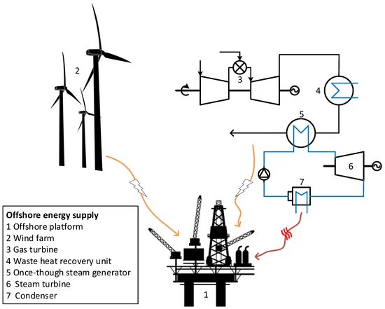
In the oil extraction process, heat is generated during a variety of operations, including thermal recovery techniques (such as steam-assisted gravity drainage or SAGD), mechanical pumping, and processing stages like separating oil from water and gas. Additionally, equipment used for pumping, compressing, and transporting oil and gas generates considerable heat that can be captured and repurposed.
While some of the heat may be used for secondary processes like maintaining temperature levels for specific chemical reactions or to improve oil flow rates, a significant portion of this thermal energy is often lost to the environment. By capturing and converting this waste heat into usable energy, operators can increase energy efficiency, reduce their operational costs, and contribute to overall sustainability in the oil extraction industry.
Technologies for Waste Heat Recovery in Oil Extraction
The most common technologies for generating electricity from waste heat in the oil extraction industry involve systems that can capture and convert thermal energy into electrical power. These systems include Organic Rankine Cycle (ORC), Kalina Cycle, and combined heat and power (CHP) technologies. These approaches allow for the recovery of heat that would otherwise be wasted, converting it into a useful form of electricity.
Organic Rankine Cycle (ORC)
The Organic Rankine Cycle (ORC) is one of the most popular waste heat recovery technologies for oil extraction because of its ability to operate effectively at lower temperatures (typically between 150°C and 400°C or 302°F and 752°F). This temperature range is common in oil extraction operations, where heat is often generated in the form of exhaust gases, hot water, or thermal energy from pumping or separating processes.
In an ORC system, the waste heat is transferred to an organic fluid with a low boiling point. This organic fluid absorbs the heat and evaporates, causing it to expand and drive a turbine or generator. The turbine generates electricity, which can be used to power the oil extraction facility itself or exported to the grid. After passing through the turbine, the expanded vapor is cooled and condensed back into liquid form, and the cycle begins again.
The ORC is particularly advantageous in oil extraction because it does not require extremely high temperatures and is efficient at recovering low-grade heat. By using organic fluids with a low boiling point, ORC systems maximize the recovery of heat that might otherwise be overlooked.
Kalina Cycle
The Kalina Cycle is another advanced technology that can be used for waste heat recovery in oil extraction. This system differs from the ORC in that it uses a mixture of water and ammonia (a working fluid with a wider boiling point range). The Kalina Cycle is capable of recovering heat from a broader range of temperatures, including lower-temperature waste heat sources in oil extraction. It is particularly suited for operations where temperatures may fluctuate or fall into a broader range, as it can optimize efficiency across a wider thermal spectrum.
In the Kalina Cycle, the heat is transferred to the ammonia-water mixture, which undergoes a phase change from liquid to vapor. The vapor then drives a turbine, producing electricity. The key advantage of the Kalina Cycle is its ability to optimize efficiency at various temperatures, making it suitable for the fluctuating heat profile that is common in oil extraction operations.
Combined Heat and Power (CHP) Systems
Combined Heat and Power (CHP) systems, also known as cogeneration systems, can also be applied to recover waste heat from oil extraction and convert it into electricity. In this setup, waste heat is used not only to generate electricity but also to provide useful thermal energy for other processes, such as heating or drying.
In a typical CHP system, exhaust gases from oil extraction equipment or combustion engines are passed through a heat recovery unit that generates steam or hot water. This steam can be used to drive a turbine connected to a generator to produce electricity. The remaining heat is either used directly in the oil extraction process or utilized for space heating, water heating, or other industrial needs, maximizing the overall efficiency of the system.
By combining the generation of both electricity and useful heat, CHP systems allow oil extraction facilities to reduce their reliance on external power sources, further lowering their operational costs. Additionally, these systems can significantly reduce greenhouse gas emissions, as they ensure that less energy is wasted in the form of excess heat.
Benefits of Waste Heat Recovery in Oil Extraction
- Energy Efficiency Improvement
The most immediate benefit of waste heat recovery is the significant improvement in energy efficiency. By capturing and converting waste heat into electricity, oil extraction facilities can reduce their reliance on external energy sources such as electricity from the grid or fossil fuels. This leads to a decrease in operational costs and a more self-sufficient energy model for oil extraction operations. - Reduction in Operating Costs
The costs associated with energy consumption in oil extraction are a major portion of the overall operational expenses. By generating electricity from waste heat, facilities can offset a significant portion of their energy needs, lowering the cost of operations over the long term. Furthermore, the reduction in fuel consumption required for heating or energy generation can lead to cost savings in other areas of the production process. - Environmental Impact Reduction
The oil and gas industry is under increasing pressure to reduce its carbon footprint and overall environmental impact. Waste heat recovery helps reduce the need for external electricity generation, which often relies on fossil fuels. By capturing and reusing waste heat, oil extraction facilities can significantly cut down on their greenhouse gas emissions. This contributes to overall efforts to mitigate climate change and complies with increasingly stringent environmental regulations. - Increased Energy Independence
Waste heat recovery systems enable oil extraction operations to become more energy-independent. By generating electricity from waste heat, companies can reduce their dependence on external power providers and stabilize their energy costs. This can be particularly important in regions where electricity prices are volatile or in remote oil extraction sites that are not connected to the grid. - Regulatory Compliance and Financial Incentives
Governments and regulatory bodies are increasingly offering financial incentives for companies that adopt energy-efficient technologies. These may include tax credits, subsidies, or other incentives for companies that implement waste heat recovery systems. By adopting such technologies, oil extraction facilities can not only reduce their energy consumption and emissions but also take advantage of these financial incentives to offset the cost of implementation. - Reputation and Market Competitiveness
As environmental concerns continue to influence consumer behavior and investment decisions, companies that prioritize sustainability and energy efficiency are likely to improve their market competitiveness. Demonstrating a commitment to reducing emissions and improving energy efficiency through waste heat recovery can enhance a company’s reputation, attract environmentally-conscious investors, and satisfy the growing demand for sustainable industrial practices.
Conclusion
Generating electricity from waste heat in oil extraction operations offers significant advantages in terms of energy efficiency, cost savings, environmental benefits, and regulatory compliance. The use of technologies like the Organic Rankine Cycle (ORC), Kalina Cycle, and Combined Heat and Power (CHP) systems enables oil extraction facilities to capture and convert waste heat into usable electricity. These systems not only help reduce energy consumption and costs but also contribute to the reduction of greenhouse gas emissions, improving the environmental footprint of the oil and gas industry. As these technologies continue to improve and costs decrease, the adoption of waste heat recovery systems will likely become more widespread, helping oil extraction facilities to operate more sustainably and efficiently in the future.
In addition to the technological advancements and the inherent benefits, there are also evolving trends that will further enhance the potential of waste heat recovery in oil extraction. As the oil and gas industry continues to face increasing pressures to adopt cleaner and more efficient energy practices, the integration of waste heat recovery systems is expected to become a standard approach for improving both economic and environmental outcomes.
Integration of Digital Technologies
The incorporation of digital technologies into waste heat recovery systems will allow oil extraction operations to optimize their performance even further. The use of the Industrial Internet of Things (IIoT) and smart sensors can provide real-time data on temperature fluctuations, heat availability, and system efficiency. By collecting this data, operators can monitor the performance of waste heat recovery systems more effectively, identifying inefficiencies or opportunities for improvement.
Advanced analytics and machine learning algorithms can also play a critical role in predicting when waste heat recovery systems are likely to be most effective. For example, these tools could optimize the integration of different heat recovery systems (such as ORC, Kalina, or CHP) depending on the heat profile at any given moment. By using predictive maintenance, operators could reduce the likelihood of system failure, enhancing system reliability and reducing downtime. Predictive analytics can also optimize energy consumption patterns, ensuring that electricity generation from waste heat matches the facility’s demand profile, further reducing reliance on external power sources.
Furthermore, digital twin technology could be employed to create a virtual model of the waste heat recovery system, allowing operators to simulate various scenarios and test potential improvements before implementing them in the real world. This proactive approach helps to ensure that waste heat recovery systems are running at peak efficiency, resulting in greater overall energy savings.
Hybrid Energy Systems and Flexibility
One of the most promising developments in waste heat recovery is the potential for hybrid energy systems, where waste heat recovery is combined with renewable energy sources, energy storage, and other energy-saving technologies. For instance, integrating solar or wind power with waste heat recovery can provide an energy mix that enhances both reliability and sustainability. These hybrid systems can allow for the generation of renewable energy even when the oil extraction facility is not producing waste heat or when heat recovery efficiency is lower.
Moreover, energy storage technologies, such as batteries or thermal storage systems, can store excess electricity generated during peak waste heat recovery periods. This electricity can then be used during times when waste heat is less available or when electricity demand increases, such as during facility shutdowns or periods of high energy consumption.
By combining waste heat recovery with renewable energy and energy storage, oil extraction facilities can achieve higher levels of energy self-sufficiency and cost savings, all while further reducing their carbon footprint. The added flexibility of such systems will enable these facilities to better adapt to varying heat profiles and external energy market fluctuations.
Global Regulatory and Market Trends
As governments around the world increase efforts to combat climate change, the oil and gas industry is likely to face stricter environmental regulations in the coming years. In many regions, carbon pricing mechanisms, carbon taxes, and cap-and-trade programs are being implemented to incentivize companies to reduce their carbon emissions. Waste heat recovery provides an effective way for oil extraction companies to lower their greenhouse gas emissions and reduce their carbon liabilities under such regulations.
Furthermore, the global market is increasingly rewarding companies that prioritize sustainability. Investors and consumers are becoming more conscious of the environmental impacts of the products they use, and this extends to the oil and gas sector. As a result, oil extraction companies that invest in waste heat recovery systems can improve their public image, attract eco-conscious investors, and secure long-term market competitiveness.
The rise of environmental, social, and governance (ESG) reporting frameworks is also pushing companies to disclose their environmental practices more transparently. Implementing waste heat recovery systems not only supports compliance with emissions regulations but also enhances a company’s ability to report positive sustainability metrics, such as reduced carbon emissions and improved energy efficiency.
Collaboration with Other Industries
Another potential avenue for the future growth of waste heat recovery in oil extraction is the possibility of collaboration with neighboring industries. In areas where oil extraction is located near other industrial operations, waste heat could be shared with nearby plants. For example, excess heat from oil extraction facilities could be used to power chemical plants, district heating systems, or even nearby residential areas.
By establishing local energy networks, the oil and gas industry could help foster a more circular economy, where waste heat becomes a shared resource that benefits multiple sectors. This type of collaboration could increase the overall energy efficiency of the entire industrial region and create a more sustainable energy ecosystem. It would also allow oil extraction companies to earn additional revenue by selling surplus electricity or heat to nearby industries.
Such cooperative energy initiatives could be further supported by government incentives and funding programs that encourage cross-sector collaboration and resource sharing. This trend could lead to a more integrated and decentralized approach to energy production, reducing waste and increasing sustainability at a regional level.
Future Outlook
Looking ahead, the continued evolution of waste heat recovery technologies and their integration into the broader energy landscape suggests a bright future for oil extraction companies that embrace these systems. As global pressure to reduce carbon emissions rises and technological advancements make waste heat recovery even more efficient and cost-effective, the oil and gas sector will increasingly turn to these systems as a viable solution for improving sustainability and reducing operational costs.
The transition to cleaner and more efficient production methods, including waste heat recovery, will not only help oil extraction facilities improve their bottom line but also contribute to the global efforts to combat climate change. By adopting waste heat recovery, oil extraction companies will play a critical role in advancing the green industrial revolution, where energy efficiency and sustainability are at the forefront of economic and environmental priorities.
In conclusion, generating electricity from waste heat in oil extraction represents a significant opportunity for improving energy efficiency, reducing operational costs, and minimizing the environmental impact of the industry. With the continued development of advanced technologies, digital tools, and hybrid energy systems, waste heat recovery will become an increasingly integral part of oil extraction processes. By embracing these technologies, oil extraction companies can position themselves as leaders in the sustainable energy transition, driving both financial and environmental success for the future.
As the global push for sustainability continues to intensify, the oil extraction industry is increasingly seeking solutions that allow it to improve its environmental footprint while maintaining productivity and profitability. Waste heat recovery is one such solution that offers considerable potential for improving both energy efficiency and environmental sustainability. However, the future of waste heat recovery in oil extraction will depend not only on technological advancements but also on evolving market dynamics, regulatory pressures, and investment trends.
Continued Technological Innovations
One of the main drivers for the future adoption of waste heat recovery in oil extraction will be technological innovation. As researchers and engineers continue to develop more advanced, cost-effective solutions for capturing and converting waste heat, the overall efficiency of these systems will improve. Innovations such as advanced materials, higher-performance thermodynamic cycles, and new types of working fluids for heat recovery systems can enable more effective energy conversion even at lower temperatures.
For instance, the development of high-efficiency thermoelectric materials, which directly convert heat into electricity, could provide a breakthrough for capturing waste heat in oil extraction operations. These materials could potentially offer greater flexibility than traditional mechanical systems like ORC and Kalina cycles, and they could be integrated into smaller-scale applications or even within specific components of the oil extraction process, such as individual pumps or compressors.
Additionally, improvements in heat exchanger technologies, such as more efficient and compact heat exchangers, will enhance the overall performance of waste heat recovery systems. The ability to better capture heat from a wider range of temperature profiles will make waste heat recovery systems more versatile, allowing them to be implemented in a variety of operational settings.
The Role of Energy Storage and Hybrid Systems
While waste heat recovery is effective at generating electricity, one challenge that remains is how to deal with fluctuations in energy demand and availability. Energy storage systems will play a critical role in enabling more consistent and reliable electricity generation from waste heat.
The integration of energy storage solutions, such as battery systems or thermal storage, with waste heat recovery systems will allow excess electricity generated during peak heat recovery periods to be stored and used when demand is higher or when waste heat is not as readily available. For example, during periods of low oil extraction activity or during maintenance shutdowns, stored energy can be released to provide power to the facility. This integration of energy storage could significantly improve the financial viability of waste heat recovery, as it reduces the need to rely on external power sources during non-peak hours.
Hybrid energy systems, combining waste heat recovery with renewable energy sources such as solar, wind, or geothermal, will further increase the flexibility of energy generation. These systems will allow for a more balanced and sustainable energy mix. For instance, if waste heat recovery is less efficient on a particular day, renewable sources like solar power can supplement energy production. Similarly, waste heat recovery can step in when renewable energy sources are unavailable, ensuring a continuous power supply.
The combination of waste heat recovery and energy storage could make oil extraction operations more resilient to external energy market fluctuations. This would be particularly beneficial for facilities located in remote areas or regions with unstable energy grids. By ensuring a reliable, self-sufficient energy system, oil extraction companies could achieve greater operational efficiency and cost savings.
Economic Incentives and Investment in Green Technologies
The transition to a more sustainable and energy-efficient oil extraction process will be heavily influenced by economic incentives and regulatory frameworks that encourage the adoption of waste heat recovery systems. Governments and industry regulators worldwide are increasingly introducing policies that incentivize the reduction of carbon emissions and the adoption of cleaner technologies.
Carbon pricing mechanisms, such as carbon taxes or cap-and-trade systems, are pushing oil extraction companies to adopt technologies that help reduce their emissions. Waste heat recovery systems can be a crucial part of this strategy, as they reduce the need for external power generation (which often involves burning fossil fuels) and lower overall greenhouse gas emissions. Moreover, companies that invest in waste heat recovery technologies can benefit from various government incentives such as tax credits, grants, and subsidies, which can offset the costs of implementation.
In some regions, environmental, social, and governance (ESG) metrics are becoming a key factor in investment decisions. Investors are increasingly interested in companies with strong sustainability practices, and oil extraction companies that adopt waste heat recovery can showcase their commitment to reducing their environmental impact. These efforts may result in greater investor confidence, improved public relations, and access to green funding, such as ESG-compliant bonds or loans.
Additionally, the growing demand for low-carbon energy solutions is leading to greater competition among oil extraction companies to implement greener technologies. In some cases, adopting waste heat recovery can serve as a differentiating factor for companies aiming to position themselves as leaders in sustainability within the oil and gas industry.
Global Collaboration and Sharing Best Practices
As waste heat recovery becomes an increasingly viable option for oil extraction operations, industry-wide collaboration will be crucial to optimizing the technology’s potential. Sharing knowledge and best practices across regions and industries can accelerate the adoption of waste heat recovery systems. International energy organizations, environmental groups, and research institutions can play a key role in fostering collaboration among oil extraction companies, technology providers, and government agencies.
For example, companies with a wealth of experience in waste heat recovery systems can share their insights and lessons learned with those who are just starting to explore the technology. This exchange of knowledge can help streamline the implementation process, reduce costs, and ensure the effective deployment of waste heat recovery systems across various types of oil extraction operations. Industry partnerships can also help address the challenges of scaling up waste heat recovery technologies, bringing down costs through economies of scale and making the systems more accessible to smaller operators.
Collaborative initiatives can extend beyond the oil and gas industry to other industrial sectors, where similar waste heat recovery technologies are being implemented. By working together across industries, it may be possible to establish a circular energy model that allows excess heat from one sector (such as oil extraction) to be shared with neighboring industries (such as chemical manufacturing, mining, or power generation), leading to greater overall energy efficiency and reducing energy waste.
Looking Toward a Sustainable Future
The future of waste heat recovery in oil extraction holds significant promise. As the technology evolves and integrates with renewable energy sources, energy storage solutions, and advanced materials, the potential for generating electricity from waste heat will continue to grow. Oil extraction facilities will become more energy-efficient, cost-effective, and environmentally sustainable, helping the industry move toward a greener future.
By investing in waste heat recovery systems, oil extraction companies can reduce their dependence on external energy sources, lower their carbon emissions, and improve their bottom line. Furthermore, as global market dynamics and regulatory landscapes shift in favor of sustainability, those companies that embrace waste heat recovery technologies early on will be well-positioned to lead the way in reducing the industry’s environmental footprint.
With continued technological advancements, collaboration, and investment in green technologies, waste heat recovery systems will play an integral role in transforming the oil extraction industry. This transformation will not only drive operational efficiencies but will also make significant contributions to the broader global effort to mitigate climate change and build a more sustainable energy future. By harnessing the power of waste heat, the oil extraction industry has the opportunity to turn a potential liability into a valuable resource, leading the way toward a cleaner, more efficient energy landscape.
Generating electricity using flue gas heat from coal-fired power plants is an important avenue for improving energy efficiency and reducing the environmental footprint of these plants. Coal-fired power plants are a major source of electricity worldwide but are also responsible for substantial emissions of greenhouse gases and other pollutants. However, capturing and utilizing the heat contained in flue gases—gases produced by the combustion of coal—offers a promising solution to mitigate the environmental impact of these plants while increasing their operational efficiency.
The Challenge of Flue Gas Heat
Flue gases generated by coal combustion are typically released at high temperatures, containing a significant amount of thermal energy. However, a substantial portion of this energy is usually lost to the atmosphere through the stack (chimney). To optimize energy use and reduce emissions, coal-fired power plants can employ various methods to capture and recover this waste heat, converting it into usable power.
One of the key challenges, however, is the composition of flue gases. In addition to water vapor and carbon dioxide, flue gases can contain sulfur dioxide (SO₂), nitrogen oxides (NOx), and particulate matter, which pose environmental and operational challenges for heat recovery systems. The presence of these pollutants can complicate the design and operation of heat recovery technologies, requiring additional equipment to ensure that they do not interfere with the recovery process or contribute to environmental degradation.
Despite these challenges, there are various technologies available to capture and utilize the heat from flue gases, which can significantly improve the overall efficiency of coal-fired power plants.
Technologies for Heat Recovery
Several heat recovery technologies can be employed in coal-fired power plants to recover flue gas heat and convert it into electricity:
- Heat Recovery Steam Generators (HRSGs): Heat recovery steam generators are commonly used in power plants to capture waste heat from flue gases. In a typical setup, the HRSG consists of a series of heat exchangers that absorb heat from the flue gases and transfer it to water or steam. The steam generated can then be used to drive a steam turbine, which produces electricity.HRSGs are particularly effective in combined-cycle power plants, where they are paired with gas turbines. The exhaust gases from the gas turbine are directed through the HRSG, where heat is captured and used to produce steam, which is then expanded through a steam turbine to generate additional electricity. This combination increases the overall efficiency of the plant, making better use of the heat produced by both the gas turbine and the coal boiler.
- Organic Rankine Cycle (ORC) Systems: The Organic Rankine Cycle is a technology similar to the traditional Rankine cycle, but it uses an organic fluid instead of water to generate steam. ORC systems are particularly well-suited for recovering heat from lower-temperature sources, such as flue gases, and converting it into electricity.In a typical ORC system, the heat from the flue gases is used to vaporize the organic fluid, which is then expanded through a turbine to generate electricity. The key advantage of ORC systems is their ability to operate at lower temperatures, making them ideal for capturing waste heat from coal-fired power plants, where the temperature of the flue gases may not be high enough for traditional steam-based cycles to be efficient.ORC systems can be integrated into existing coal-fired power plants to capture waste heat from the flue gases, improving the overall energy conversion efficiency of the plant.
- Flue Gas Desulfurization (FGD) Combined with Heat Recovery: Coal-fired power plants often use flue gas desulfurization (FGD) systems to remove sulfur dioxide from the flue gases before they are released into the atmosphere. These systems, which typically use a lime or limestone slurry to scrub the sulfur from the gases, can also be integrated with heat recovery technologies to improve efficiency.One option is to use the heat from the flue gases to regenerate the chemicals used in the FGD system. By utilizing the heat that would otherwise be wasted, the regeneration process becomes more energy-efficient. Additionally, the recovered heat can be used to generate steam or electricity, reducing the plant’s overall reliance on external energy sources.
- Thermal Energy Storage (TES) Systems: Thermal energy storage systems can complement waste heat recovery efforts by storing excess heat generated during periods of high heat recovery, which can then be used to generate electricity during periods of lower heat availability. TES systems, such as molten salt or phase-change material storage, can capture excess heat from flue gases and store it for later use.By storing heat at high temperatures, these systems enable coal-fired power plants to decouple their electricity generation from fluctuating demand or variations in flue gas temperature. This results in a more stable and flexible energy supply, helping to optimize the overall efficiency of the power plant.
Benefits of Waste Heat Recovery in Coal-fired Power Plants
- Improved Efficiency: By capturing and utilizing the heat from flue gases, coal-fired power plants can significantly improve their overall energy efficiency. Heat recovery systems such as HRSGs and ORC systems increase the amount of usable energy extracted from the combustion process, leading to a reduction in fuel consumption and operating costs. In some cases, overall efficiency improvements of 10–20% can be achieved, depending on the specific technology used and the heat recovery system’s integration into the plant.
- Reduced Emissions: One of the main motivations for capturing flue gas heat is to reduce emissions. By improving efficiency, waste heat recovery systems help to reduce the amount of fuel required to produce electricity, which in turn reduces the emissions of carbon dioxide (CO₂), sulfur dioxide (SO₂), and other harmful pollutants. This reduction in emissions is particularly important in the context of global efforts to combat climate change and meet international emissions reduction targets.Furthermore, by using heat recovery systems, coal-fired power plants can decrease their reliance on cooling towers and other equipment that contribute to water consumption and thermal pollution, improving their environmental footprint.
- Cost Savings: While the initial investment in waste heat recovery technologies can be significant, the long-term cost savings can make these systems financially attractive. By reducing the need for additional fuel and improving operational efficiency, coal-fired power plants can lower their fuel costs and increase profitability. The additional electricity generated from recovered heat can also offset energy purchases from external sources, further reducing operational expenses.Additionally, many governments offer incentives, subsidies, or tax breaks for implementing clean energy technologies, including waste heat recovery systems. These financial incentives can help offset the upfront costs and make waste heat recovery a more viable option for coal-fired power plants.
- Energy Resilience: Waste heat recovery systems can contribute to the energy resilience of coal-fired power plants by enabling them to produce more electricity from the same amount of fuel. During periods of fluctuating fuel prices or other disruptions in the energy supply, the ability to recover heat and generate additional power can help ensure a reliable and stable electricity supply. In some cases, waste heat recovery can also enable power plants to maintain a consistent level of operation even when there are fluctuations in fuel quality or availability.
Future Prospects and Challenges
The integration of waste heat recovery technologies into coal-fired power plants represents a significant opportunity for improving the efficiency and sustainability of coal-based electricity generation. However, there are challenges that need to be addressed for broader adoption.
- Cost of Implementation: The initial capital investment for waste heat recovery systems, such as HRSGs or ORC units, can be significant. This can be a barrier for older coal-fired plants that may not have the capital available to retrofit with new systems. However, ongoing cost reductions and advancements in technology are expected to make these systems more affordable in the future.
- Regulatory and Policy Support: The effectiveness of waste heat recovery will depend on the regulatory and policy environment. Governments must create incentives and supportive regulations to encourage the adoption of these systems. This includes carbon pricing, emissions reduction targets, and funding for research and development of new heat recovery technologies.
- Technology Development: While existing waste heat recovery technologies are already effective, further innovations are needed to optimize their performance. Advances in materials science, turbine design, and heat exchanger technology will likely drive future improvements in system efficiency and cost-effectiveness.
Conclusion
Generating electricity from flue gas heat in coal-fired power plants is a promising strategy for improving energy efficiency and reducing the environmental impact of coal-based power generation. By implementing heat recovery technologies such as HRSGs, ORC systems, and thermal energy storage, coal plants can generate additional power from waste heat, reduce their reliance on external fuel sources, and lower their emissions. As technology advances and economic and regulatory pressures continue to push for cleaner energy solutions, the role of waste heat recovery in coal-fired power plants is likely to expand, contributing to a more sustainable and energy-efficient future.
While the adoption of waste heat recovery technologies in coal-fired power plants offers numerous benefits, there are still several hurdles to overcome to achieve widespread implementation. In addition to the technical, financial, and regulatory challenges mentioned earlier, some plant-specific factors must be considered when implementing heat recovery systems.
Consideration of Plant-Specific Factors
Each coal-fired power plant operates under unique conditions depending on its age, location, capacity, and the type of coal it uses. When considering the integration of waste heat recovery systems, plant operators must assess factors such as:
- Flue Gas Temperature and Composition: The temperature and composition of the flue gases can vary significantly across plants and combustion processes. For example, older plants may produce flue gases with lower temperatures, making it more difficult to recover significant amounts of heat. Additionally, the specific chemical makeup of the flue gases—such as the presence of sulfur compounds or particulate matter—can impact the design and efficiency of recovery systems. Some heat recovery technologies may be better suited to particular temperature ranges or types of waste heat, requiring a tailored approach for each facility.
- Space and Layout Constraints: Coal-fired power plants, particularly older facilities, may not have the space available to install additional equipment for waste heat recovery systems. The integration of technologies such as HRSGs or ORC systems may require significant modifications to the plant’s infrastructure, potentially disrupting ongoing operations. Space constraints can also limit the ability to implement energy storage solutions or additional cooling systems needed for waste heat recovery. Plant operators must carefully evaluate the feasibility of retrofitting their facilities with these technologies.
- Operational Flexibility: Waste heat recovery systems should be designed to work seamlessly with the plant’s existing operations. Coal-fired power plants often have fluctuating operational conditions, including changes in load demand, fuel quality, and environmental regulations. Recovery systems must be adaptable to these changes, ensuring that they can operate efficiently across a wide range of conditions. For example, ORC systems or HRSGs may need to be adjusted to respond to changes in flue gas temperature or flow rate, which can vary with operational conditions.
- Economic Lifespan of Existing Plants: Older coal-fired power plants may face higher costs in retrofitting or upgrading to integrate waste heat recovery technologies. In some cases, the existing equipment may be nearing the end of its operational life, making investment in advanced heat recovery systems a less attractive option. However, for plants that still have significant remaining operational life, the long-term cost savings and environmental benefits of waste heat recovery can make retrofitting worthwhile.
Advanced Heat Recovery Techniques for High-Performance Plants
As waste heat recovery technology continues to evolve, several advanced techniques are being developed to maximize the efficiency of these systems. These approaches target higher levels of performance, integrating newer technologies and design features to extract more value from the heat available.
- Supercritical and Ultra-Supercritical Steam Cycles: Many modern coal-fired power plants now operate with supercritical or ultra-supercritical steam cycles. These cycles operate at higher pressures and temperatures than traditional subcritical cycles, enabling higher thermal efficiency. The integration of waste heat recovery systems with these advanced cycles can result in significant performance improvements, as they can efficiently capture even small amounts of waste heat from the flue gases. In some cases, a supercritical steam cycle combined with heat recovery can push overall plant efficiency to levels above 45%, significantly reducing fuel consumption and emissions.
- Advanced Heat Exchanger Materials: One challenge with capturing waste heat from flue gases is the potential for corrosion and fouling of heat exchangers. Advanced materials, such as high-performance alloys or ceramic coatings, are being developed to withstand the harsh conditions of flue gas environments. These materials can enhance the durability and efficiency of heat exchangers, reducing the need for frequent maintenance and improving the longevity of heat recovery systems. Enhanced heat transfer capabilities of these materials also allow for more compact and efficient designs, reducing the overall footprint of the system.
- Multi-Stage Heat Recovery Systems: To further maximize the utilization of waste heat, multi-stage heat recovery systems are being implemented in some plants. These systems capture heat at multiple stages in the flue gas stream, rather than relying on a single stage of heat recovery. By progressively capturing heat at different temperature levels, plants can achieve higher overall thermal efficiency. For example, lower-temperature flue gases that would typically be discarded can be used to preheat air or water for other parts of the plant, creating additional opportunities for energy savings.
- Integrated Combined Heat and Power (CHP) Systems: In some coal-fired power plants, waste heat recovery is being integrated with combined heat and power (CHP) systems. These systems generate both electricity and useful heat for industrial processes or district heating. By utilizing waste heat in a CHP configuration, plants can achieve even higher levels of efficiency and reduce their overall fuel consumption. For example, steam generated by an HRSG could be used to provide heat to nearby industrial facilities, providing a dual benefit of electricity generation and heat supply.
Addressing Environmental and Regulatory Pressures
Given the growing pressure to reduce emissions and transition to cleaner energy sources, integrating waste heat recovery into coal-fired power plants can help meet regulatory requirements and improve plant sustainability. As international climate agreements and national policies push for stronger emissions reductions, coal plants that incorporate waste heat recovery technologies are better positioned to comply with emissions standards.
- Carbon Emission Reductions: By improving the thermal efficiency of coal plants, waste heat recovery systems can reduce the amount of coal needed to generate electricity. This, in turn, lowers the amount of carbon dioxide (CO₂) emitted per unit of electricity generated. In regions with stringent carbon pricing or emissions trading schemes, this reduction can lead to financial savings by lowering carbon compliance costs.
- Regulatory Compliance with Air Quality Standards: Waste heat recovery systems that reduce the need for additional fuel consumption can also help plants meet air quality standards. By improving efficiency and lowering fuel usage, coal-fired power plants can decrease the amount of sulfur dioxide (SO₂), nitrogen oxides (NOx), and particulate matter emitted. In some cases, waste heat recovery systems can be integrated with flue gas treatment technologies (such as flue gas desulfurization) to achieve even greater reductions in harmful pollutants.
- Future Flexibility in Transitioning to Low-Carbon Energy Sources: As the world transitions to low-carbon energy systems, waste heat recovery may also provide a stepping stone for coal-fired plants to adopt cleaner technologies. For example, captured heat could be used to support the integration of renewable energy sources, such as solar or biomass, into the plant’s operations. In the future, hybrid systems that combine fossil fuels with renewable energy sources may become more common, and waste heat recovery can play a vital role in enabling a smoother transition.
Conclusion
The integration of waste heat recovery technologies into coal-fired power plants presents a unique opportunity to enhance the efficiency of these facilities, reduce environmental emissions, and improve energy security. While the challenges of implementing such systems are not insignificant, the benefits of capturing and utilizing flue gas heat—ranging from cost savings to improved environmental performance—make it a promising solution for modernizing coal-based power generation. Continued advancements in heat recovery technologies, materials, and system design will further optimize the potential of waste heat recovery, making it an integral part of the effort to achieve cleaner and more efficient power generation worldwide.
As we move forward with the integration of waste heat recovery in coal-fired power plants, several considerations will shape the future of this technology and its role in the broader energy landscape.
Emerging Trends and Innovations in Waste Heat Recovery
The waste heat recovery sector is evolving rapidly with the advancement of new technologies and design concepts aimed at further improving efficiency, cost-effectiveness, and environmental sustainability. These innovations are expected to drive the widespread adoption of heat recovery systems in coal-fired power plants and other industrial applications.
- Digitalization and Smart Controls: The use of digital tools, sensors, and predictive analytics is becoming increasingly important in optimizing the performance of waste heat recovery systems. Advanced monitoring and control systems can provide real-time data on plant operations, flue gas composition, and temperature fluctuations, allowing operators to optimize the performance of heat recovery systems. These smart systems can adjust the operation of heat exchangers, turbines, and other components in real time, ensuring that the maximum amount of heat is captured and converted into electricity while minimizing wear and tear on the equipment. Predictive maintenance tools can also detect potential issues before they lead to equipment failure, reducing downtime and improving the reliability of heat recovery systems.
- Integration of Artificial Intelligence (AI) and Machine Learning (ML): Artificial intelligence and machine learning algorithms are increasingly being used to enhance decision-making and optimize the operation of waste heat recovery systems. These technologies can analyze vast amounts of operational data to identify patterns, predict performance under various conditions, and suggest adjustments to optimize efficiency. For example, AI can help fine-tune the operation of ORC systems or HRSGs by predicting when to initiate or shut down recovery processes based on factors such as fuel quality, operational load, or ambient conditions. This can result in greater energy savings, reduced operational costs, and improved plant performance over time.
- Advanced Heat Storage Solutions: One of the limitations of waste heat recovery systems in coal-fired power plants is the intermittent nature of heat availability. Flue gas temperatures can fluctuate depending on operational conditions, making it difficult to maintain a constant flow of recovered heat. Advanced thermal energy storage (TES) solutions, such as high-temperature molten salt storage or advanced phase-change materials, are being developed to store excess heat generated during periods of high availability and release it during periods of lower heat availability. These storage systems can improve the overall flexibility and efficiency of waste heat recovery by decoupling heat recovery from real-time plant operations.
- Hybrid Systems with Renewable Energy: The future of coal-fired power plants may involve hybrid systems that combine waste heat recovery with renewable energy sources, such as solar, wind, or biomass. These hybrid systems allow plants to reduce their reliance on coal while still maintaining a steady power supply. For example, excess heat recovered from coal combustion could be used to support the operation of renewable energy technologies, such as concentrating solar power (CSP) systems or biomass boilers. By integrating renewable energy sources with waste heat recovery systems, coal plants can reduce their carbon emissions and move towards a more sustainable energy model while maintaining reliability and grid stability.
- Carbon Capture, Utilization, and Storage (CCUS) Integration: As part of the global effort to mitigate climate change, carbon capture, utilization, and storage (CCUS) technologies are being developed to capture carbon dioxide emissions from power plants and industrial facilities. Waste heat recovery systems can play an important role in supporting CCUS technologies by providing the additional thermal energy needed for CO₂ capture processes. For example, the heat recovered from flue gases could be used to regenerate solvents in a post-combustion capture system, improving the efficiency and economic viability of carbon capture. By combining waste heat recovery with CCUS, coal-fired power plants can significantly reduce their greenhouse gas emissions, contributing to global decarbonization efforts.
- Lower-Cost Heat Recovery Materials and Technologies: The continued development of new materials and manufacturing techniques is helping to lower the cost of heat recovery systems. Advances in heat exchanger design, such as the use of more efficient and cost-effective materials (e.g., carbon fiber or high-strength alloys), are making it easier to scale up heat recovery technologies for broader use. Additionally, new manufacturing techniques, such as 3D printing, are enabling the rapid prototyping of custom-designed heat exchangers and other system components, reducing the time and cost associated with system deployment. These innovations are expected to make waste heat recovery systems more accessible and affordable for coal-fired power plants, especially those in developing countries where energy infrastructure is still expanding.
Policy and Regulatory Drivers for Waste Heat Recovery
Governments around the world are beginning to recognize the importance of waste heat recovery as a means of improving energy efficiency, reducing emissions, and advancing toward climate goals. Several policy and regulatory drivers are likely to influence the future of waste heat recovery in coal-fired power plants.
- Emissions Reduction Targets: As countries set increasingly ambitious emissions reduction targets under international climate agreements (such as the Paris Agreement), coal-fired power plants will face greater pressure to reduce their carbon footprint. Waste heat recovery technologies can help plants achieve these goals by increasing efficiency and reducing fuel consumption, which leads to lower CO₂ emissions. As a result, governments may introduce stricter regulations on energy efficiency and carbon emissions, encouraging plants to adopt heat recovery solutions.
- Carbon Pricing and Tax Incentives: In regions where carbon pricing or cap-and-trade systems are in place, coal-fired power plants that adopt waste heat recovery technologies may benefit from lower carbon compliance costs. By reducing their carbon emissions through increased efficiency, plants can lower their exposure to carbon taxes or emissions permits. In addition, tax credits, grants, and subsidies may be available to incentivize the adoption of clean technologies, including waste heat recovery. These financial incentives can make heat recovery systems more financially viable for power plant operators, particularly in the early stages of adoption.
- Energy Efficiency Standards: Many countries are setting stricter energy efficiency standards for power plants and industrial facilities. These standards often include requirements for waste heat recovery, encouraging the deployment of technologies that improve the overall energy efficiency of coal-fired plants. By incorporating waste heat recovery systems into their operations, coal-fired power plants can meet these regulatory requirements and avoid penalties for non-compliance.
- Transition to Clean Energy Incentives: As part of the global shift toward clean energy, governments may offer incentives for coal-fired plants to adopt cleaner technologies, such as waste heat recovery, to reduce their environmental impact. These incentives could take the form of grants for research and development, favorable financing terms for retrofitting projects, or mandates to increase energy recovery in industrial processes. By encouraging the adoption of cleaner technologies, governments can help facilitate the transition from fossil fuels to low-carbon energy sources while maintaining energy security.
Environmental and Social Impacts of Waste Heat Recovery
The integration of waste heat recovery technologies in coal-fired power plants offers a range of environmental and social benefits, contributing to a cleaner and more sustainable energy future.
- Reduction in Greenhouse Gas Emissions: One of the most significant environmental benefits of waste heat recovery is the reduction in greenhouse gas emissions. By improving the efficiency of coal-fired power plants, these systems help reduce the amount of coal burned, which directly lowers CO₂ emissions. In addition to CO₂ reductions, heat recovery can also lower the emissions of other pollutants, such as sulfur dioxide (SO₂), nitrogen oxides (NOx), and particulate matter, which contribute to air pollution and acid rain.
- Conservation of Resources: By maximizing the use of energy that would otherwise be wasted, waste heat recovery systems help conserve valuable resources. Coal is a finite resource, and using it more efficiently through heat recovery reduces the need for excessive extraction and burning of coal. This, in turn, reduces the environmental impact of mining and transportation activities associated with coal production.
- Job Creation and Economic Development: The widespread adoption of waste heat recovery systems can stimulate job creation in the energy and manufacturing sectors. This includes jobs related to the design, construction, installation, and maintenance of heat recovery technologies, as well as those involved in the production of advanced materials and components. In regions with a high concentration of coal-fired power plants, the implementation of waste heat recovery can also provide economic benefits by improving plant profitability and reducing the cost of energy for local communities.
- Energy Access and Reliability: By improving the efficiency and reliability of coal-fired power plants, waste heat recovery can enhance energy access in regions that rely on coal for electricity generation. The increased efficiency of these plants can help meet growing energy demands while minimizing the environmental impact. In developing countries, waste heat recovery systems can provide a cost-effective way to increase power production without significantly increasing fuel consumption or emissions.
Conclusion
The future of coal-fired power plants lies in the adoption of technologies that enhance efficiency, reduce emissions, and improve overall sustainability. Waste heat recovery offers a key solution by enabling coal plants to capture and convert waste heat into useful electricity. With ongoing technological advancements, regulatory support, and environmental incentives, the integration of waste heat recovery systems is poised to play a crucial role in reducing the carbon footprint of coal-based power generation.
As the global energy landscape continues to evolve, waste heat recovery systems will contribute not only to the efficiency of coal-fired power plants but also to the broader transition toward cleaner, more sustainable energy systems. By embracing these innovations, coal-fired power plants can continue to play a role in the energy mix while minimizing their environmental impact and improving energy security for communities worldwide.
EMS Power Machines
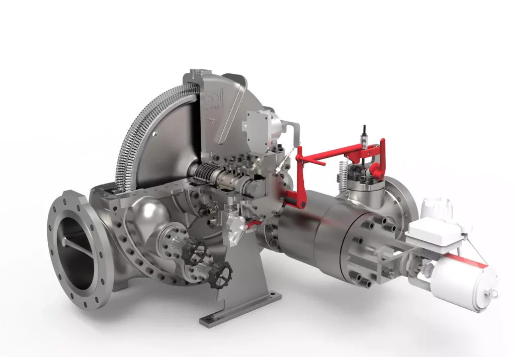
We design, manufacture and assembly Power Machines such as – diesel generators, electric motors, vibration motors, pumps, steam engines and steam turbines
EMS Power Machines is a global power engineering company, one of the five world leaders in the industry in terms of installed equipment. The companies included in the company have been operating in the energy market for more than 60 years.
EMS Power Machines manufactures steam turbines, gas turbines, hydroelectric turbines, generators, and other power equipment for thermal, nuclear, and hydroelectric power plants, as well as for various industries, transport, and marine energy.
EMS Power Machines is a major player in the global power industry, and its equipment is used in power plants all over the world. The company has a strong track record of innovation, and it is constantly developing new and improved technologies.
Here are some examples of Power Machines’ products and services:
- Steam turbines for thermal and nuclear power plants
- Gas turbines for combined cycle power plants and industrial applications
- Hydroelectric turbines for hydroelectric power plants
- Generators for all types of power plants
- Boilers for thermal power plants
- Condensers for thermal power plants
- Reheaters for thermal power plants
- Air preheaters for thermal power plants
- Feedwater pumps for thermal power plants
- Control systems for power plants
- Maintenance and repair services for power plants
EMS Power Machines is committed to providing its customers with high-quality products and services. The company has a strong reputation for reliability and innovation. Power Machines is a leading provider of power equipment and services, and it plays a vital role in the global power industry.
EMS Power Machines, which began in 1961 as a small factory of electric motors, has become a leading global supplier of electronic products for different segments. The search for excellence has resulted in the diversification of the business, adding to the electric motors products which provide from power generation to more efficient means of use.